Craftsman 919184191 User Manual AIR COMPRESSOR Manuals And Guides L0310412
CRAFTSMAN Air compressor Manual L0310412 CRAFTSMAN Air compressor Owner's Manual, CRAFTSMAN Air compressor installation guides
User Manual: Craftsman 919184191 919184191 CRAFTSMAN AIR COMPRESSOR - Manuals and Guides View the owners manual for your CRAFTSMAN AIR COMPRESSOR #919184191. Home:Tool Parts:Craftsman Parts:Craftsman AIR COMPRESSOR Manual
Open the PDF directly: View PDF ![]() .
.
Page Count: 60
Owner's Manual
I (RRFTSMRNq
Oil Lubricated
Single Stage
Vertical Stationary
AIR COMPRESSOR
Model No.
919.184191
•Safety Guidelines
•Assembly
•Operation
•Maintenance
•Service and Adjustments
•Troubleshooting
•Repair Parts
•Espahol
CAUTION: Read the Safety Guidelines
and All Instructions Carefully Before
Operating.
Sears, Roebuck and Co., Hoffman Estates, IL 60170 U.S.A.
Visit our Craftsman website: www.sears.com/craftsman
D30091 Rev. 0 9/26/03
WARRANTY ................................................ 2
SPECIFICATION CHART ..................................... 3
SAFETY GUIDELINES ...................................... 3-8
GLOSSARY ................................................ 9
ACCESSORIES ............................................. 9
DUTY CYCLE .............................................. 9
ASSEMBLY ............................................... 10
INSTALLATION .......................................... 11-13
OPERATION ............................................ 14-16
MAINTENANCE ......................................... 17-19
SERVICE AND ADJUSTMENTS ............................ 20-21
STORAGE ................................................ 22
TROUBLESHOOTING GUIDE .............................. 24-27
REPAIR PARTS ......................................... 28-31
ESPAI_IOL .............................................. 32-57
NOTES .................................................. 58
REPAIR PROTECTION AGREEMENTS ......................... 59
HOW TO ORDER REPAIR PARTS ...................... back cover
FULL ONE YEAR WARRANTY AIR COMPRESSOR
If this CRAFTSMAN Air Compressor fails due to a defect in material or
workmanship within one year from the date of purchase, Sears will at its
option repair or replace it free of charge. Contact your nearest Sears Service
Center (1-800-4-MY-HOME ®)to arrange for repair, or return the Air
Compressor to the place of purchase for replacement.
If this Air Compressor is used for commercial or rental purposes, this warrant
applies for only ninety days from the date of purchase.
This warranty gives you specific legal rights and you may have other rights
which vary from state to state.
Sears, Roebuck and Co., Dept. 817WA, Hoffman Estates, IL 60179
D30091 2- ENG
-_".J=[a_I; [.'7,21d[1] _Iif'-1:II
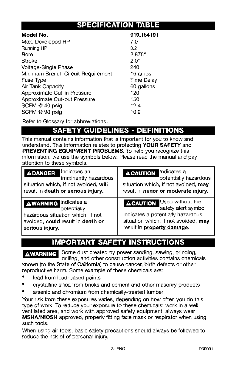
Model No. 919.184191
Max. Developed HP 7.0
Running HP 3.2
Bore 2.875"
Stroke 2.0"
Voltage-Single Phase 240
Minimum Branch Circuit Requirement 15 amps
Fuse Type Time Delay
Air Tank Capacity 60 gallons
Approximate Cut-in Pressure 120
Approximate Cut-out Pressure 150
SCFM @ 40 psig 12.4
SCFM @ 90 psig 10.2
Refer to Glossary for abbreviations.
This manual contains information that is important for you to know and
understand. This information relates to protecting YOUR SAFETY and
PREVENTING EQUIPMENT PROBLEMS. To help you recognize this
information, we use the symbols below. Please read the manual and pay
attention to these symbols.
_"_F"4'_ Indicat es an
imminently hazardous
situation which, if not avoided, will
result in death or serious injury.
_lndicates a
potentially
hazardous situation which, if not
avoided, could result in death or
serious injury.
_T_llndicates a
potentially hazardous
situation which, if not avoided,
result in minor or moderate injury.
_'_lUsed without the
safety alert symbol
indicates a potentially hazardous
situation which, if not avoided, may
result in property damaee.
_J Some dust created by power sanding, sawing, grinding,
drilling, and other construction activities contains chemicals
known (to the State of California) to cause cancer, birth defects or other
reproductive harm. Some example of these chemicals are:
• lead from lead-based paints
• crystalline silica from bricks and cement and other masonry products
• arsenic and chromium from chemically-treated lumber
Your risk from these exposures varies, depending on how often you do this
type of work. To reduce your exposure to these chemicals: work in a well
ventilated area, and work with approved safety equipment, always wear
MSNA/NIOSR approved, properly fitting face mask or respirator when using
such tools.
When using air tools, basic safety precautions should always be followed to
reduce the risk of of personal injury.
3* ENG D30091
II_ I_o] ;111P'.'q+IInl[,.'9'.,__1_ &'i __JL_[,._)III,_]LI_+']IIT[_o_+]L_,[,._
Save these instructions
Improper operation or maintenance of this product could result in serious injury and
property damage. Read and understand all warnings and operation instructions before
using this equipment,
,l;1"l'J "-In
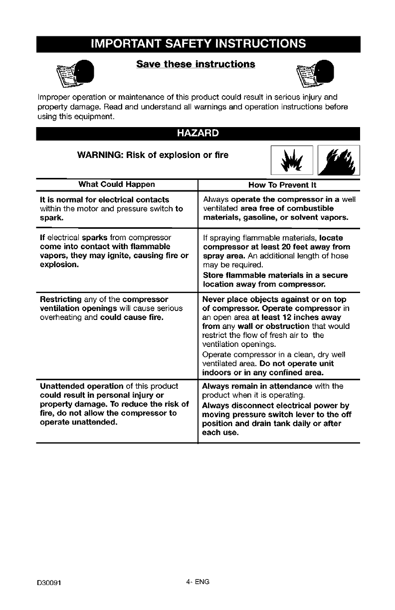
WARNING: Risk of explosion or fire
What Could Happen How To Prevent It
It is normal for electrical contacts Always operate the compressor in a well
within the motor and pressure switch to ventilated area free of combustible
spark, materials, gasoline, or solvent vapors.
If electrical sparks from compressor If spraying flammable materials, locate
come into contact with flammable compressor at least 20 feet away from
vapors, they may ignite, causing fire or spray area. An additional length of hose
explosion, may be required,
Store flammable materials in a secure
location away from compressor.
Restricting any of the compressor
ventilation openings will cause serious
overheating and could cause fire,
Unattended operation of this product
could result in personal injury or
property damage. To reduce the risk of
fire, do not allow the compressor to
operate unattended.
Never place objects against or on top
of compressor. Operate compressor in
an open area at least 12 inches away
from any wall or obstruction that would
restrict the flow of fresh air to the
ventilation openings.
Operate compressor in a clean, dry wall
ventilated area. Do not operate unit
indoors or in any confined area.
Always remain in attendance with the
)roduct when it is operating.
Always disconnect electrical power by
moving pressure switch lever to the off
}osition and drain tank daily or after
each use.
D30091 4* ENG
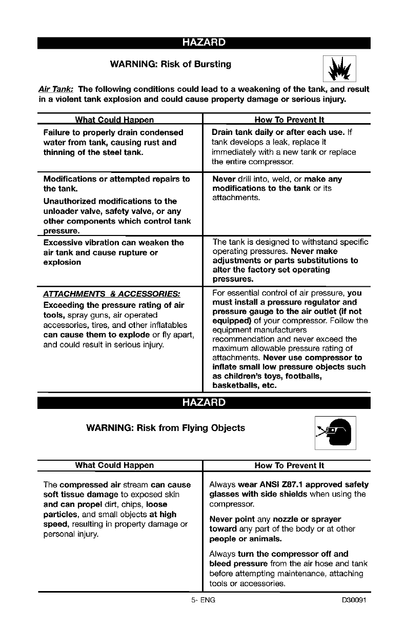
WARNING: Risk of Bursting
Air Tank: The following conditions could lead to a weakening of the tank, and result
in a violent tank explosion and could cause property damage or serious injury,
What Could Haopen How To Prevent It
Failure to properly drain condensed Drain tank daily or after each use. If
water from tank, causing rust and tank develops a leak, replace it
thinning of the steel tank. immediately with a new tank or replace
the entire compressor.
Modifications or attempted repairs to Never drill into, weld, or make any
the tank. modifications to the tank or its
Unauthorized modifications to the attachments.
unloader valve, safety valve, or any
other components which control tank
pressure.
Excessive vibration can weaken the The tank is designed to withstand specific
air tank and cause rupture or operating pressures. Never make
explosion adjustments or parts substitutions to
alter the factory set operating
pressures=
ATTACHMENTS & ACCESSORIES:
Exceeding the pressure rating of air
tools, spray guns, air operated
accessories, tires, and other inflatables
can cause them to explode or fly apart,
and could result in serious injury.
For essential control of air pressure, you
must install a pressure regulator and
pressure gauge to the air outlet (if not
equipped) of your compressor. Follow the
equipment manufacturers
recommendation and never exceed the
maximum allowable pressure rating of
attachments. Never use compressor to
inflate small low pressure objects such
as children's toys, footballs,
basketballs, etc.
WARNING: Risk from Flying Objects
What Could Happen How To Prevent It
The compressed air stream can cause
soft tissue damage to exposed skin
and can propel dirt, chips, loose
particles, and small objects at high
speed, resulting in property damage or
personal injury.
Always wear ANSI Z87.1 approved safety
glasses with side shields when using the
compressor.
Never point any nozzle or sprayer
toward any part of the body or at other
people or animals.
Always turn the compressor off and
bleed pressure from the air hose and tank
before attempting maintenance, attaching
to0_s Oi" accessories,
5* ENG D30091
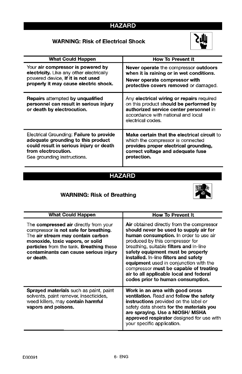
WARNING: Risk of Electrical Shock
What Could Happen How To Prevent It
Your air compressor is powered by Never operate the compressor outdoors
electricity. Like any other electrically when it is raining or in wet conditions.
powered device, If it is not used Never operate compressor with
properly it may cause electric shock. }retactive covers removed or damaged.
Repairs attempted by unqualified Any electrical wiring or repairs required
personnel can result in serious injury on this product should be performed by
or death by electrocution, authorized service center personnel in
accordance with national and local
electrical codes.
Electrical Grounding: Failure to provide Make certain that the electrical circuit to
adequate grounding to this product which the compressor is connected
could result in serious injury or death provides proper electrical grounding,
from electrocution, correct voltage and adequate fuse
See grounding instructions. _retection.
WARNING: Risk of Breathing
What Could Happen How To Prevent It
The compressed air directly from your
compressor is not safe for breathing.
The air stream may contain carbon
monoxide, toxic vapors, or solid
particles from the tank. Breathing these
contaminants can cause serious injury
or death.
Sprayed matadals such as paint, paint
solvents, paint remover, insecticides,
weed killers, may contain harmful
vapors and poisons.
Air obtained directly from the compressor
should never be used to supply air for
human consumption. In order to use air
)roduced by this compressor for
breathing, suitable filters and in-line
safety equipment must be properly
installed. In-line filters and safety
equipment used in conjunction with the
compressor must be capable of treating
air to all applicable local and federal
codes prior to human consumption.
Work in an area with good cross
ventilation. Read and follow the safety
instructions provided on the label or
safety data sheets for the materials you
are spraying. Use a NIOSH/MSHA
approved respirator designed for use with
your specific application.
D30091 6* ENG
:r:_rJ:_;!m
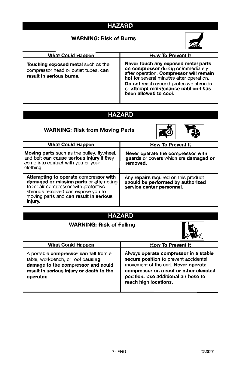
WARNING: Risk of Burns
What Could Happen
Touching exposed metal such as the
compressor head or outlet tubes, can
result in serious burns.
How To Prevent It
Never touch any exposed metal parts
on compressor during or immediately
after operation. Compressor will remain
hot for several minutes after operation.
Do not reach around protective shrouds
or attempt maintenance until unit has
been allowed to cool.
:r:_rJ:_;!=
WARNING: Risk from Moving Parts
What Could Happen How To Prevent It
Moving parts such as the pulley, flywheel, Never operate the compressor with
and belt can cause serious injury if they guards or covers which are damaged or
come into contact with you or your removed.
clothing.
Attempting to operate compressor with Any repairs required on this product
damaged or missing parts or attempting should be performed by authorized
to repair compressor with protective service center personnel.
shrouds removed can expose you to
moving parts and can result in serious
injury.
:r:_rJ:_;!=
WARNING: Risk of Falling
What Could Happen How To Prevent It
Aportable compressor can fall from a Always operate compressor in a stable
table, workbench, or roof causing secure position to prevent accidental
damage to the compressor and could movement of the unit. Never operate
result in serious injury or death to the compressor on a roof or other elevated
operator, position. Use additional air hose to
reach high locations.
7÷ ENG D30091
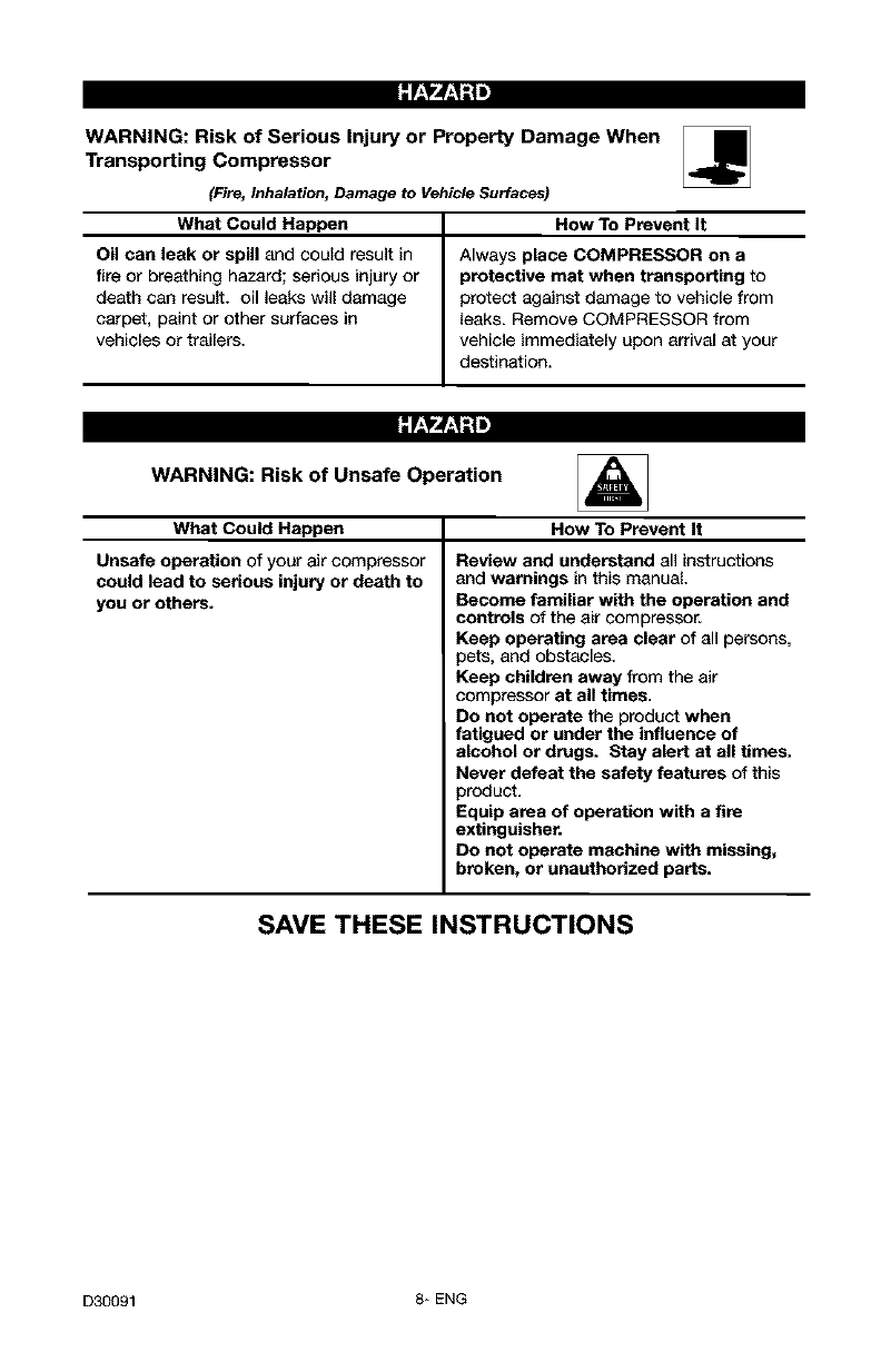
WARNING: Risk of Serious Injury or Property Damage When
Transporting Compressor
(Fire, Inhalation, Damage to VehicleSurfaces)
What Could Happen How To Prevent It
Oil can leak or spill and could result in Always place COMPRESSOR on a
fire or breathing hazard; serious injury or protective mat when transporting to
death can result, oil leaks will damage protect against damage to vehicle from
carpet, paint or other surfaces in leaks. Remove COMPRESSOR from
vehicles or trailers, vehicle immediately upon arrival at your
destination.
WARNING: Risk of Unsafe Operation _1=
What Could Happen How To Prevent It
Unsafe operation of your air compressor
could lead to serious injury or death to
you or others.
Review and understand all instructions
and warnings in this manual.
Become familiar with the operation and
controls of the air compressor.
Keep operating area clear of all persons,
pets, and obstacles.
Keep children away from the air
compressor at all times.
Do not operate the product when
fatigued or under the influence of
alcohol or drugs. Stay alert at all times.
Never defeat the safety features of this
product.
Equip area of operation with a fire
extinguisher.
DO not operate machine with missing,
broken, or unauthorized parts.
SAVE THESE INSTRUCTIONS
D30091 8* ENG
Become familiar with these terms
before operating the unit.
CFM: Cubic feet per minute.
SCFM: Standard cubic feet per
minute; aunit of measure of air
delivery.
PSlG: Pounds per square inch
gauge; a unit of measure of pressure.
Code Certification: Products that
bear one or more of the following
marks: UL, CUL, ETL, CETL, have
been evaluated by OSHA certified
independent safety laboratories and
meet the applicable Underwriters
Laboratories Standards for Safety.
Cut-In Pressure: While the motor is
off, air tank pressure drops as you
continue to use your accessory.
When the tank pressure drops to a
certain low level the motor will restart
automatically. The low pressure at
which the motor automatically
restarts is called "cut-in" pressure.
Cut-Out Pressure: When an air
compressor is turned on and begins
to run, air pressure in the air tank
begins to build. It builds to a certain
high pressure before the motor
automatically shuts off - protecting
your air tank from pressure higher
than its capacity. The high pressure
at which the motor shuts off is called
"cut-out" pressure.
Branch Circuit: Circuit carrying
electricity from electrical panel to
outlet.
This unit is capable of powering the following Accessories. The accessories are
available through the current Power and Hand Tool Catalog or full-line Sears
stores.
Accessories
• In Line Filter
• Tire Air Chuck
• Quick Connector Sets (various
sizes)
• Air Pressure Regulators
• Oil Fog Lubricators
• Air Hose: 1/4", 5/16", or 3/8" OR
1/2" inside diameter in various
lengths
ml_Tujj_[e,_ q=1
This air compressor pump is capable
of running continuously. However, to
prolong the life of your air
compressor, it is recommended that a
50%-75% average duty cycle be
maintained; that is, the air
compressor pump should not run
more than 30-45 minutes in any given
hour.
9- ENG D30091
Tools Required for Assembly
1-9/16" socket or open end wrench
1 - electric drill
Unpacking
1. Remove all packaging.
It may be
necessary to brace
or support one side of the air
compressor when removing the
pallet because the air compressor
will have a tendency to tip.
2. Remove and discard the (4)
screws and washers holding the
compressor to the pallet.
3. With the help of another person
carefully remove air compressor
from pallet and place on a level
surface.
Adding Oil To Pump
Compressors are
shipped without oil.
A small amount of oil may be
present in the pump upon receipt
of the air compressor. This is due
to plant testing and does not mean
the pump contains oil. Do not
attempt to operate this air
compressor without first adding oil
to the crankcase. Serious damage
can result from even limited
operation unless filled with oil and
broken in correctly. Make sure to
closely follow initial start-up
procedures.
I_[_I_ Use air compressor
oil only. Multi-
Viscosity motor oils, like lOW 30,
should not be used in an air
compressor. They leave carbon
deposits on critical components,
thus reducing performance and
compressor life.
NOTE: Use an air compressor oil
such as Sears item number 9-16426
or SAE-20 (API CG/CD) heavy duty
motor oil. Under extreme winter
conditions use SAE-10 weight oil.
To Add Oil
Drain tank to
release air pressure
before removing the oil fill cap or
oil drain plug.
1. Place unit on a level surface.
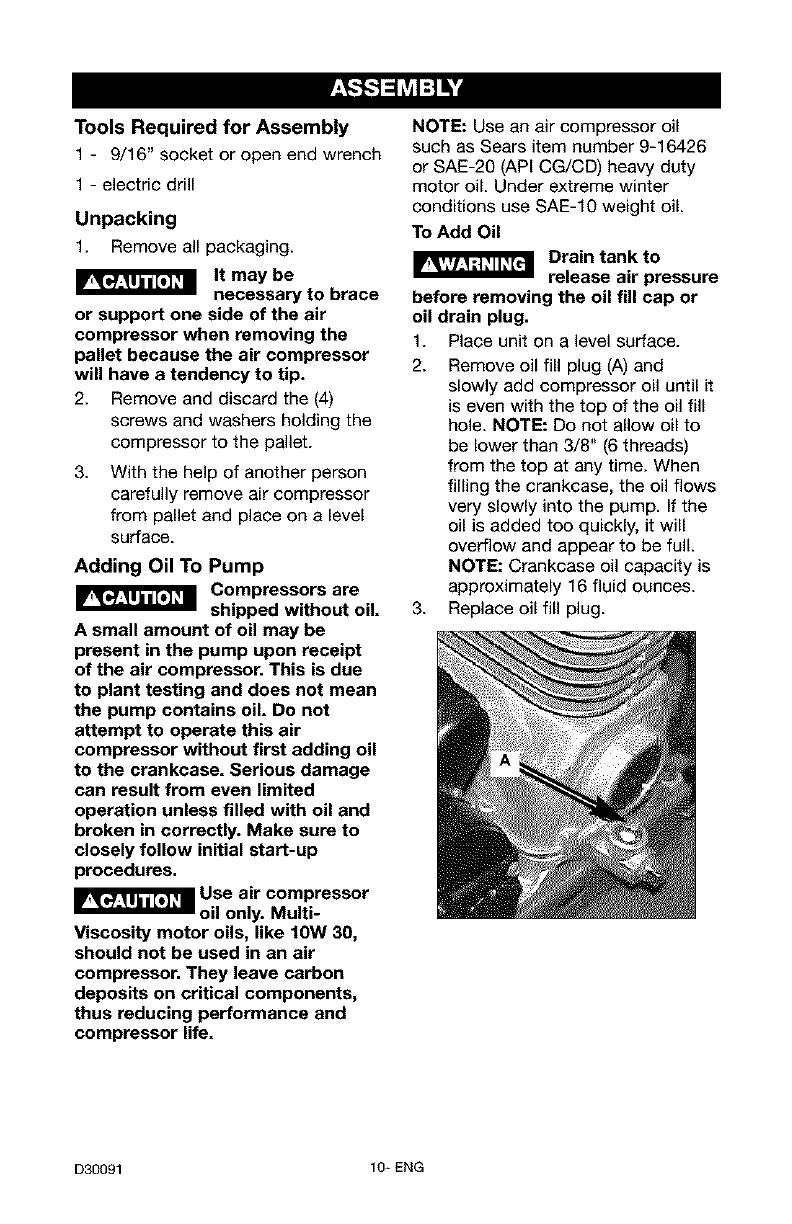
2. Remove oil fill plug (A) and
slowly add compressor oil until it
is even with the top of the oil fill
hole. NOTE: Do not allow oil to
be lower than 3/8" (6 threads)
from the top at any time. When
filling the crankcase, the oil flows
very slowly into the pump. If the
oil is added too quickly, it will
overflow and appear to be full.
NOTE: Crankcase oil capacity is
approximately 16 fluid ounces.
3. Replace oil fill plug.
D30091 10_ ENG
HOW TO SET UP YOUR
UNIT
Air Compressor Location
•Locate the air compressor in a
clean, dry, and well ventilated
area.
• Locate the air compressor at
least 12" away from the wall or
other obstructions that will
interfere with the flow of air.
• Locate the air compressor as
close to the main power supply
as possible to avoid using long
lengths of electrical wiring.
NOTE: Long lengths of electrical
wiring could cause power loss to
the motor.
• The air filter must be kept clear
of obstructions which could
reduce air flow to the air
compressor.
Anchoring of the Air
Compressor
_Excessive vibration
can weaken the air
tank and cause an explosion. The
compressor must be properly
mounted,
The air compressor MUST be bolted
to a solid, level surface.
Hardware needed:
4 - Concrete anchors (not
supplied)
4 - 3/8" Lag screw to fit
concrete anchors (not
supplied)
4 - 5/8" Washer (found in parts
bag)
- shims (if needed)
1. Place the air compressor on a
solid, level surface.
2. Mark the surface using the holes
in the air compressor feet as a
template.
3.
4.
5.
Drill holes in the surface for the
concrete anchors. Install
concrete anchors.
Line up holes in surface with
holes in air compressor feet.
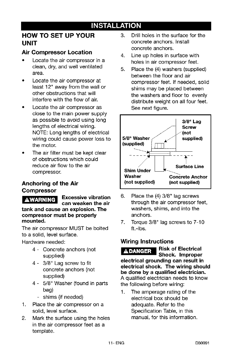
Place the (4) washers (supplied)
between the floor and air
compressor feet. If needed, solid
shims may be placed between
the washers and floor to evenly
distribute weight on all four feet.
See next figure.
3/8" Lag
// IScrew
_ _(not
5/8" Washer ¢/ ,j supplied)
(supplied) [__
_Surface Line
Shim Under
Washer Co_crete Anchor
(not supplied) (not supplied)
6.
7.
Place the (4) 3/8" lag screws
through the air compressor feet,
washers, shims, and into the
anchors.
Torque 3/8" lag screws to 7-10
ft.-Ibs.
Wiring Instructions
I_-J_-;_ Risk of Electrical
Shock. Improper
electrical grounding can result in
electrical shock. The wiring should
be done by a qualified electrician.
A qualified electrician needs to know
the following before wiring:
1. The amperage rating of the
electrical box should be
adequate. Refer to the
Specification Table, in this
manual, for this information.
11_ ENG D30091
2. The supply line should have the
same electrical characteristics
(voltage, cycle, phase) as the
motor. Refer to the motor
nameplate, on side of motor, for
this information.
NOTE: The supply voltage must be
the same as the motor nameplate
voltage plus or minus 10%. Refer to
local codes for correct wire size and
maximum wire run; undersize wire
causes high amp draw and
overheating of the motor.
Risk of Electrical
Shock. Electrical
wiring must be located away from
hot surfaces such as manifold
assembly, compressor outlet tubes,
heads, or cylinders.
GROUNDING INSTRUCTIONS
This product should be connected to
a metallic, permanent wiring system,
or an equipment-grounding terminal
or lead on the product.
Grounding location is clearly
indicated on compressor.
Voltage and Circuit Protection
Refer to the specification chart for the
voltage and minimum branch circuit
requirements.
Risk of Unsafe
Operation. Certain
air compressors can be operated
on a 15 amp circuit if the following
conditions are met.
1. Voltage supply to circuit must
comply with the National
Electrical Code.
2. Circuit is not used to supply any
other electrical needs.
3. Extension cords comply with
specifications.
4. Circuit is equipped with a 15
amp circuit breaker or 15 amp
time delay fuse. NOTE: If
compressor is connected to a
circuit protected by fuses, use
only time delay fuses. Time delay
fuses should be marked "D" in
Canada and "T" in the US.
If any of the above conditions cannot
be met, or if operation of the
compressor repeatedly causes
interruption of the power, it may be
necessary to operate it from a 20
amp circuit. It is not necessary to
change the cord set.
Air Distribution System
Risk of Bursting.
Plastic or PVC pipe
is not designed for use with
compressed air. Regardless of its
indicated pressure rating, plastic
pipe can burst from air pressure.
Usa only metal pipe for air
distribution lines.
The next figure represents a typical
air distribution system. The following
are tips to remember when setting up
the air compressor's air distribution
system.
Use pipe that is the same size as
the air tank outlet. Piping that is
too small will restrict the flow of
air.
• If piping is over 100 feet long,
use the next larger size.
Bury underground lines below
the frost line and avoid pockets
where condensation can gather
and freeze. Fill lines with air
pressure before covering to
make sure pipe joints are free
from leaks.
D30091 12- ENG
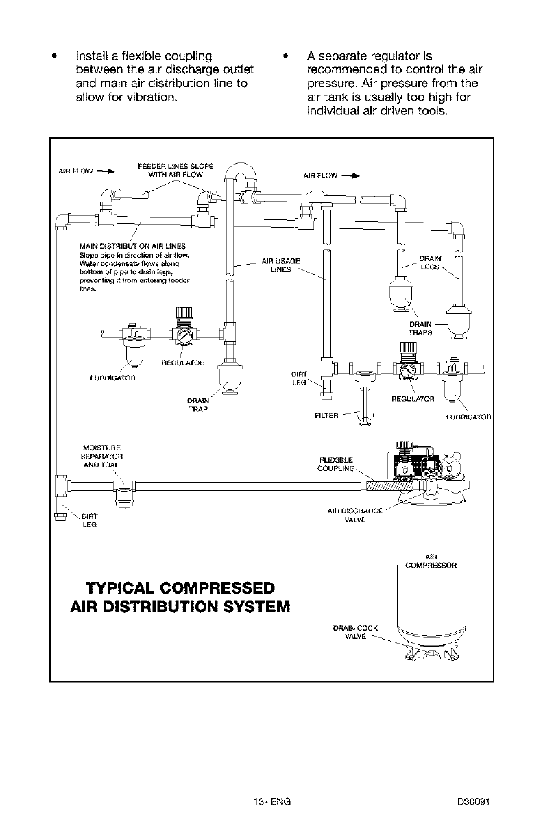
Install a flexible coupling
between the air discharge outlet
and main air distribution line to
allow for vibration.
A separate regulator is
recommended to control the air
pressure. Air pressure from the
air tank is usually too high for
individual air driven tools.
DRAIN
_'g__
LEG
o%u%_
AIR D_SCHARGE J
VALVE
TYPICAL COMPRESSED
AIR DISTRIBUTION SYSTEM
DRAIN COCK
VA LVE
AiR
COMpReSSOR
13_ ENG D30091
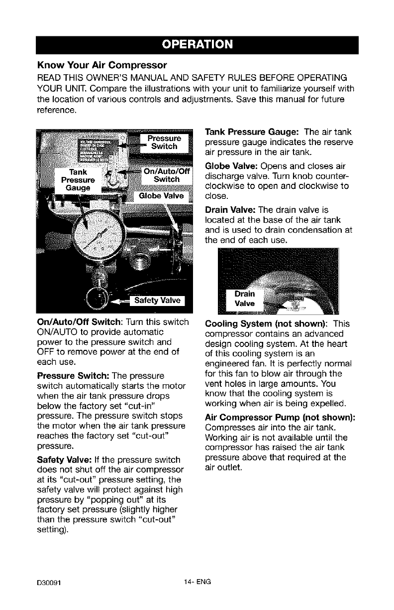
Know Your Air Compressor
READ THIS OWNER'S MANUAL AND SAFETY RULES BEFORE OPERATING
YOUR UNIT. Compare the illustrations with your unit to familiarize yourself with
the location of various controls and adjustments. Save this manual for future
reference.
Tank Pressure Gauge: The air tank
pressure gauge indicates the reserve
air pressure in the air tank.
Globe Valve: Opens and closes air
discharge valve. Turn knob counter-
clockwise to open and clockwise to
close.
Drain Valve: The drain valve is
located at the base of the air tank
and is used to drain condensation at
the end of each use.
On/Auto/Off Switch: Turn this switch
ON/AUTO to provide automatic
power to the pressure switch and
OFF to remove power at the end of
each use.
Pressure Switch: The pressure
switch automatically starts the motor
when the air tank pressure drops
below the factory set "cut-in"
pressure. The pressure switch stops
the motor when the air tank pressure
reaches the factory set "cut-out"
pressure.
Safety Valve: If the pressure switch
does not shut off the air compressor
at its "cut-out" pressure setting, the
safety valve will protect against high
pressure by "popping out" at its
factory set pressure (slightly higher
than the pressure switch "cut-out"
setting).
Cooling System (not shown): This
compressor contains an advanced
design cooling system. At the heart
of this cooling system is an
engineered fan. It is perfectly normal
for this fan to blow air through the
vent holes in large amounts. You
know that the cooling system is
working when air is being expelled.
Air Compressor Pump (net shown):
Compresses air into the air tank.
Working air is not available until the
compressor has raised the air tank
pressure above that required at the
air outlet.
D30091 14_ ENG

Check Valve: When the air
compressor is operating, the check
valve is "open", allowing compressed
air to enter the air tank. When the air
compressor reaches "cut-out"
pressure, the check valve "closes",
allowing air pressure to remain inside
the air tank.
Pressure Release Valve: The
pressure release valve, located on the
side of the pressure switch, is
designed to automatically release
compressed air from the compressor
head and the outlet tube when the air
compressor reaches "cut-out"
pressure or is shut off. The pressure
release valve allows the motor to
restar_ freely. When the motor stops
running, air will be heard escaping
from this valve for a few seconds.
No air should be heard leaking when
the motor is running or after unit
reaches "cut-out" pressure.
Air Intake Filter (not shown) This
filter is designed to clean air coming
into the pump. This filter must always
be clean and ventilation openings
free from obstructions. See
"Maintenance".
How to Use Your Unit
How to Stop:
1. Set the On/Auto/Off lever to
"OFF".
Before First Start-up
Risk of Unsafe
Operation. Serious
damage may result if the following
break-in instructions are not
closely followed.
This procedure is required before the
air compressor is put into service the
first time and when the check valve
or a complete compressor pump has
been replaced.
Break-in Instructions
1.
2.
Make sure the On/Auto/Off lever
is in the "OFF" position.
Recheck all wiring. Make sure
wires are secure at all terminals
connections. Make sure all
contacts move freely and are not
obstructed.
3. Open the globe valve fully to
permit air to escape and prevent
air pressure build-up in the air
tank during the break-in period.
4. Move the On/Auto/Off lever to
"ON/AUTO" position. The
compressor will start.
5. Run the compressor for 20
minutes. Make sure the globe
valve is open and check tank
pressure gauge for minimal air
pressure build-up in air tank.
6. Check all air line fittings and
connections/piping for air leaks
by applying a soap solution to
them. Bubbles will indicate a
leak. Correct if necessary. NOTE:
Minor leaks can cause the air
compressor to overwork,
resulting in premature breakdown
or inadequate performance.
7. Check for excessive vibration.
Readjust or shim air compressor
feet, if necessary.
8. After 20 minutes, close the globe
valve.The air tank will fill to "cut-
out" pressure and the motor will
stop.
15_ ENG D30091
Before Each Start-Up:
f. Place On/Auto/Off lever to
"OFF".
2. Close the globe valve.
3. Attach hose and accessories.
NOTE: A regulator MUST be
installed when using accessories
rated at less than 120 PSI.
Risk of Bursting.
Too much air
pressure causes a hazardous risk
of the air tank bursting, Check the
manufacturer's maximum pressure
rating for air tools and accessories,
The regulator outlet pressure must
never exceed the maximum
pressure rating.
How to Start
1. Turn the On/Auto/Off lever to
"AUTO" and allow air tank
pressure to build. Motor will
stop when air tank pressure
reaches "cut-out" pressure.
2. When the air tank pressure
reaches "cut-out" pressure open
the globe valve.
IMPORTANT: When using regulator
and other accessories refer to the
manufacturer's instructions.
D30091 16_ ENG
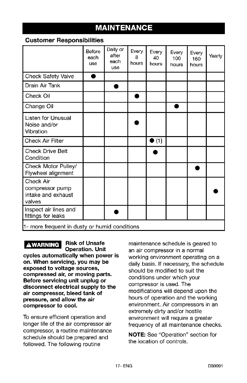
Customer Responsibilities
Before Dallyor Every Every Every Every
each after 8 40 100 160 Yearly
use each hours hours hours hours
use
Check Safety Valve •
Drain Air Tank •
Check 0il •
Change Oil •
Listen for Unusual
Noise and/or •
Vibration
Check Air Filter • (1)
Check Drive Belt •
Condition
Check Motor Pulley/ •
Flywheel alignment
Check Air
compressor pump •
intake and exhaust
valves
Inspect air lines and •
fittings for leaks
1- more frequent in dusty or humid conditions
Risk of Unsafe
Operation. Unit
cycles automatically when power is
on. When servicing, you may be
exposed to voltage sources,
compressed air, or moving parts.
Before servicing unit unplug or
disconnect electrical supply to the
air compressor, bleed tank of
pressure, and allow the air
compressor to cool.
To ensure efficient operation and
longer life of the air compressor air
compressor, a routine maintenance
schedule should be prepared and
followed. The following routine
maintenance schedule is geared to
an air compressor in a normal
working environment operating on a
daily basis. If necessary, the schedule
should be modified to suit the
conditions under which your
compressor is used. The
modifications will depend upon the
hours of operation and the working
environment. Air compressors in an
extremely dirty and/or hostile
environment will require a greater
frequency of all maintenance checks.
NOTE: See "Operation" section for
the location of controls.
17_ ENG D30091
To Check Safety Valve
Risk of Bursting. If
the safety valve
does not work properly, over-
pressurization may occur, causing
air tank rupture or explosion and
possible serious injury.
1. Before starting compressor, pull
the ring on the safety valve to
make sure that the safety valve
operates freely. If the valve is
stuck or does not operate
smoothly, it must be replaced
with the same type of valve.
To Drain Air tank
1. Set the On/Auto/Off lever to
"OFF" and disconnect electrical
supply.
2. Close the globe valve.
3. Remove the air tool or
accessory.
4. Open the globe valve and allow
the air to slowly bleed from the
air tank until tank pressure is
approximately 20 psi.
5. Close the globe valve.
6. Drain water from air tank by
opening drain valve (counter-
clockwise) on bottom of air tank.
Risk of Bursting.
Ip,,,,i._ ;t=,ii_[d Water will
condense in the air tank. If not
drained, water will corrode and
weaken the air tank causing a risk
of air tank rupture and possible
serious injury.
7. After the water has been drained,
close the drain valve (clockwise).
The air compressor can now be
stored.
NOTE: If drain valve is plugged,
release all air pressure. The valve
can then be removed, cleaned, then
reinstalled.
Oil
I_ Risk of Bursting.
Drain air tank to
release air pressure before removing
the oil fill cap or oil drain plug.
NOTE: Use air compressor oil such
as SAE-20 (API CG/CD) heavy duty
motor oil. Under extreme winter
conditions use SAE-10 weight oil. Oil
capacity is approximately 16 fluid
ounces.
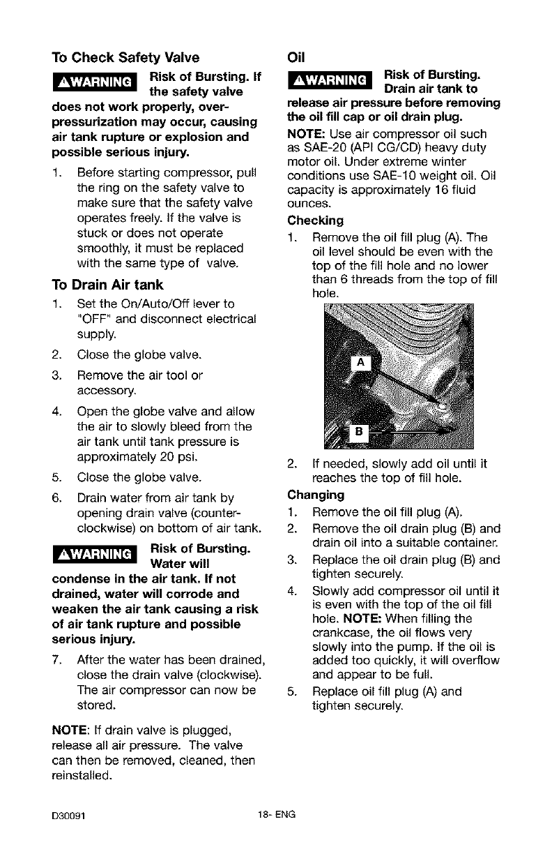
Checking
1. Remove the oil fill plug (A). The
oil level should be even with the
top of the fill hole and no lower
than 6 threads from the top of fill
hole.
2. If needed, slowly add oil until it
reaches the top of fill hole.
Changing
1. Remove the oil fill plug (A).
2. Remove the oil drain plug (B) and
drain oil into a suitable container.
3. Replace the oil drain plug (B) and
tighten securely.
4. Slowly add compressor oil until it
is even with the top of the oil fill
hole. NOTE: When filling the
crankcase, the oil flows very
slowly into the pump. If the oil is
added too quickly, it will overflow
and appear to be full.
5. Replace oil fill plug (A) and
tighten securely.
D30091 18_ ENG
Air Filter Inspection and
Replacement
Risk of Burns.
Compressor head
and cylinder sleeve are very hot.
Do not touch. Allow compressor to
cool prior to servicing.
A dirty air filter will not allow the
compressor to operate at full
capacity. Keep the air filter clean at
all times.
1. Remove
the air filter
cover.
2. Remove
the air filter
from filter
cover.
IMPORTANT:
Do not operate
the compressor with the air filter
removed.
3. Place new air filter into filter
cover. Refer to the "Repair Parts"
for the correct part number.
4. Replace air filter cover and lock
into place.
Motor Pulley/Flywheel Alignment
NOTE: Once the motor pulley has
been moved from its factory set
location, the grooves of the flywheel
and pulley must be aligned to within
1/16" to prevent excessive belt wear.
The air compressor flywheel and motor
pulley must be in-line (in the same
plane) within 1/16" to assure belt
retention within flywheel belt grooves.
To check alignment, perform the
following steps:
1. Disconnect electrical supply to the
air compressor
2. Remove belt guard.
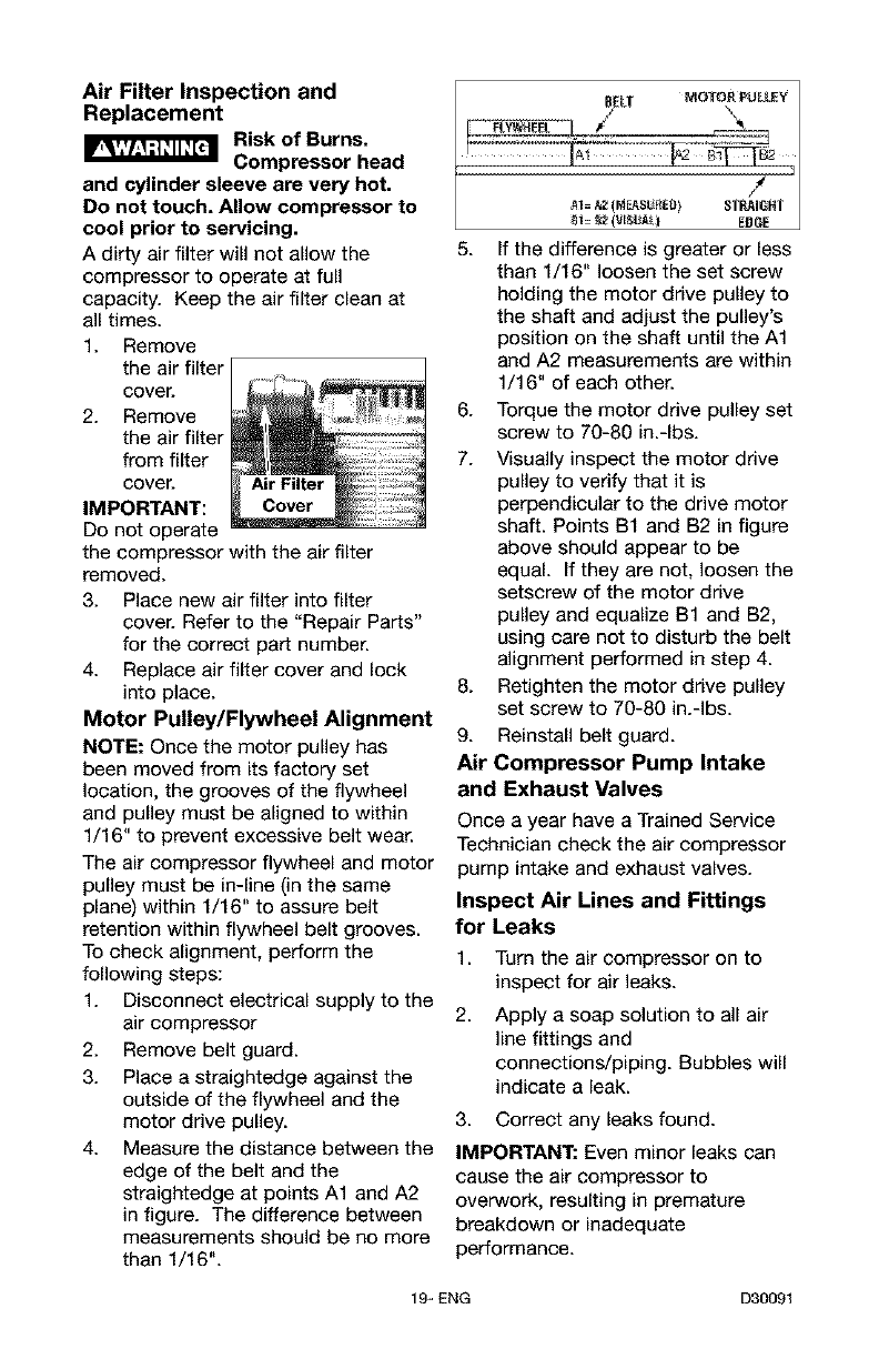
3. Place a straightedge against the
outside of the flywheel and the
motor drive pulley.
4. Measure the distance between the
edge of the belt and the
straightedge at points A1 and A2
in figure. The difference between
measurements should be no more
than 1/16".
5. If the difference is greater or tess
than 1/16" loosen the set screw
holding the motor drive pulley to
the shaft and adjust the pulley's
position on the shaft until the A1
and A2 measurements are within
1/16" of each other.
6. Torque the motor drive pulley set
screw to 70-80 in.-Ibs.
7. Visually inspect the motor drive
pulley to verify that it is
perpendicular to the drive motor
shaft. Points B1 and B2 in figure
above should appear to be
equal. If they are not, loosen the
setscrew of the motor drive
pulley and equalize B1 and B2,
using care not to disturb the belt
alignment performed in step 4.
8. Retighten the motor drive pulley
set screw to 70-80 in.-Ibs.
9. Reinstall belt guard.
Air Compressor Pump Intake
and Exhaust Valves
Once a year have a Trained Service
Technician check the air compressor
pump intake and exhaust valves.
Inspect Air Lines and Fittings
for Leaks
1. Turn the air compressor on to
inspect for air leaks.
2, Apply a soap solution to all air
line fittings and
connections/piping. Bubbles will
indicate a leak.
3. Correct any leaks found.
IMPORTANT: Even minor leaks can
cause the air compressor to
overwork, resulting in premature
breakdown or inadequate
performance.
19_ ENG D30091
ALL SERVICE AND REPAIR
OPERATIONS NOT DESCRIBED IN
THIS MANUAL MUST BE
PERFORMED BY A TRAINED
SERVICE TECHNICIAN.
Risk of Unsafe
Operation. Unit
cycles automatically when power is
on. When servicing, you may be
exposed to voltage sources,
compressed air, or moving parts.
Before servicing unit unplug or
disconnect electrical supply to the
air compressor, bleed tank of
pressure, and allow the air
compressor to cool.
To Replace or Clean Check
Valve
1. Release all air pressure from air
tank. See "To Drain Air tank" in
the Maintenance section.
2. Disconnect electrical supply to
the air compressor
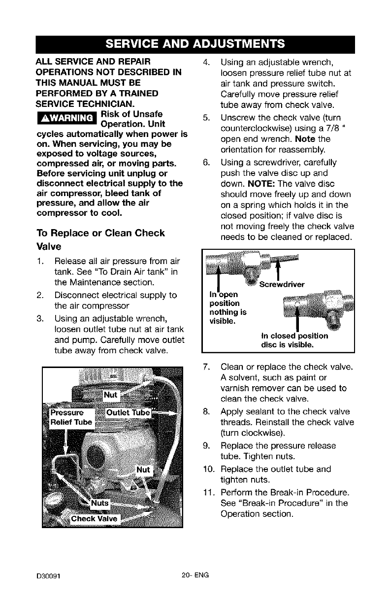
3. Using an adjustable wrench,
loosen outlet tube nut at air tank
and pump. Carefully move outlet
tube away from check valve.
4. Using an adjustable wrench,
loosen pressure relief tube nut at
air tank and pressure switch.
Carefully move pressure relief
tube away from check valve.
5. Unscrew the check valve (turn
counterclockwise) using a 7/8 "
open end wrench. Note the
orientation for reassembly.
6. Using a screwdriver, carefully
push the valve disc up and
down. NOTE: The valve disc
should move freely up and down
on a spring which holds it in the
closed position; if valve disc is
not moving freely the check valve
needs to be cleaned or replaced.
open
position
nothing is
visible.
tn closed position
disc is visible.
7. Clean or replace the check valve.
A solvent, such as paint or
varnish remover can be used to
clean the check valve.
8. Apply sealant to the check valve
threads. Reinstall the check valve
(turn clockwise).
9. Replace the pressure release
tube. Tighten nuts.
10. Replace the outlet tube and
tighten nuts.
11. Perform the Break-in Procedure.
See "Break-in Procedure" in the
Operation section.
D30091 20_ ENG
Motor
This motor has a manual thermal
overload protector. If the motor
overheats for any reason, the
overload protector will shut off the
motor. The motor must be allowed to
cool down before restarting. To
restart:
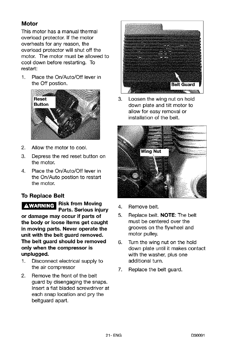
1. Place the On/Auto/Off lever in
the Off postion.
2.
3.
4.
Allow the motor to cool.
Depress the red reset button on
the motor.
Place the On/Auto/Off lever in
the On/Auto postion to restart
the motor.
To Replace Belt
_[_ Risk from Moving
Parts. Serious injury
or damage may occur if parts of
the body or loose items get caught
in moving parts. Never operate the
unit with the belt guard removed.
The belt guard should be removed
only when the compressor is
unplugged.
1. Disconnect electrical supply to
the air compressor
2. Remove the front of the belt
guard by disengaging the snaps.
Insert a flat bladed screwdriver at
each snap location and pry the
beltguard apart.
3. Loosen the wing nut on hold
down plate and tilt motor to
allow for easy removal or
installation of the belt.
4. Remove belt.
5. Replace belt. NOTE: The belt
must be centered over the
grooves on the flywheel and
motor pulley.
6. Turn the wing nut on the hold
down plate until it makes contact
with the washer, plus one
additional turn.
7. Replace the belt guard.
21_ ENG D30091
Before you store the air compressor,
make sure you do the following:
1. Review the "Maintenance"
section on the preceding pages
and perform scheduled
maintenance as necessary.
2. Set the On/Auto/Off lever to
"OFF" and disconnect electrical
supply.
3. Close the globe valve.
4. Remove the air tool or accessory.
5. Open the globe valve and allow
the air to slowly bleed from the
air tank until tank pressure is
approximately 20 psi.
6. Drain water from air tank by
opening drain valve (counter-
clockwise) on bottom of air tank.
Risk of Bursting.
Water will
condense in the air tank. If not
drained, water will corrode and
weaken the air tank causing a risk
of air tank rupture and possible
serious personal injury.
7. After the water has been drained,
close the drain or drain valve.
NOTE: If drain valve is plugged,
release all air pressure. The valve
can then be removed, cleaned, and
reinstalled.
8. Protect the air hose from
damage (such as being stepped
on or run over).
D30091 22- ENG
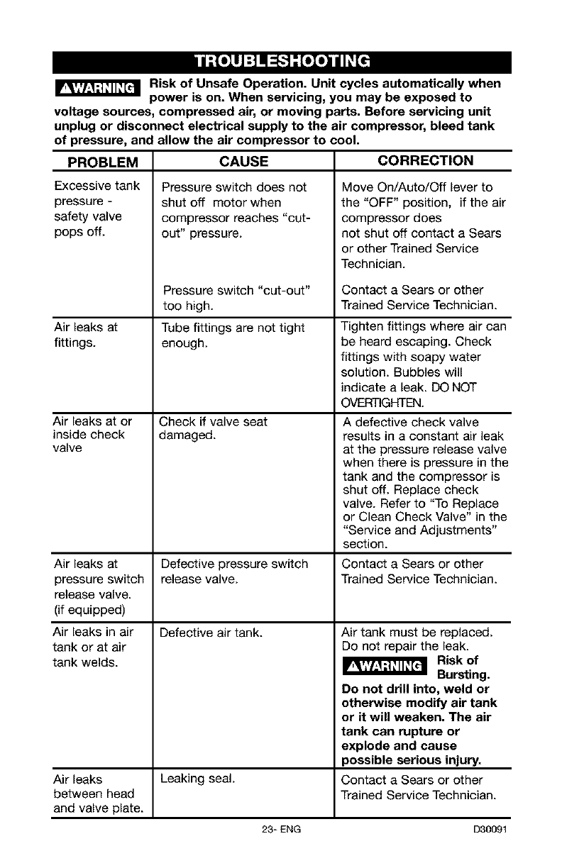
h| -'Toll:J_oXo_
Risk of Unsafe Operation. Unit cycles automatically when
power is on. When servicing, you may be exposed to
voltage sources, compressed air, or moving parts. Before servicing unit
unplug or disconnect electrical supply to the air compressor, bleed tank
of pressure, and allow the air compressor to cool.
PROBLEM
Excessive tank
pressure -
safety valve
pops off.
Air leaks at
fittings.
CAUSE CORRECTION
Pressure switch does not
shut off motor when
compressor reaches "cut-
out" pressure.
Pressure switch "cut-out"
too high.
Tube fittings are not tight
enough.
Check if valve seat
damaged.
Air leaks at or
inside check
valve
Move On/Auto/Off lever to
the "OFF" position, if the air
compressor does
not shut off contact a Sears
or other Trained Service
Technician.
Contact a Sears or other
Trained Service Technician.
Tighten fittings where air can
be heard escaping. Check
fittings with soapy water
solution. Bubbles will
indicate a leak. DO NOT
OVERTIGHTEN.
A defective check valve
results in a constant air leak
at the pressure release valve
when there is pressure in the
tank and the compressor is
shut off. Replace check
valve. Refer to "To Replace
or Clean Check Valve" in the
"Service and Adjustments"
section.
Air leaks at Defective pressure switch Contact a Sears or other
pressure switch release valve. Trained Service Technician.
release valve.
(if equipped)
Air leaks in air Defective air tank.
tank or at air
tank welds.
Air tank must be replaced.
Do not repair the leak.
Risk of
Bursting.
Do not drill into, weld or
otherwise modify air tank
or it will weaken. The air
tank can rupture or
explode and cause
_ossible serious injury.
Air leaks Leaking seal. Contact a Sears or other
between head Trained Service Technician.
and valve plate.
23_ ENG D30091
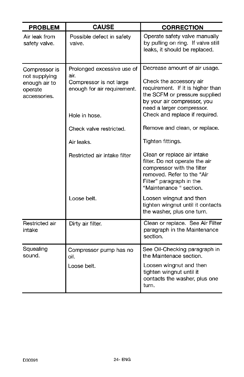
PROBLEM CAUSE CORRECTION
Air leak from Possible defect in safety Operate safety valve manually
safety valve, valve, by pulling on ring. If valve still
leaks, it should be replaced.
Decrease amount of air usage.
Compressor is
not supplying
enough air to
operate
accessories.
Restricted air
intake
Squealing
sound.
Prolonged excessive use of
air.
Compressor is not large
enough for air requirement.
Hole in hose.
Check valve restricted.
Air leaks.
Restricted air intake filter
Loose belt.
Dirty air filter.
Compressor pump has no
oil.
Loose belt.
Check the accessory air
requirement. If it is higher than
the SCFM or pressure supplied
by your air compressor, you
need a larger compressor.
Check and replace if required.
Remove and clean, or replace.
Tighten fittings.
Clean or replace air intake
filter. Do not operate the air
compressor with the filter
removed. Refer to the "Air
Filter" paragraph in the
"Maintenance" section.
Loosen wingnut and then
tighten wingnut until it contacts
the washer, plus one turn.
Clean or replace. See Air Filter
paragraph in the Maintenance
section.
See Oil-Checking paragraph in
the Maintenace section.
Loosen wingnut and then
tighten wingnut untilit
contacts the washe£ plus one
turn.
D30091 24_ ENG
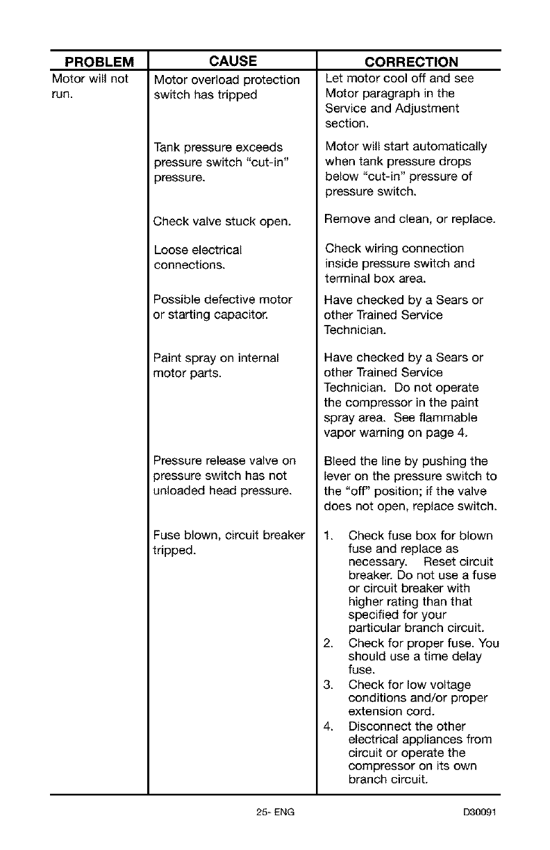
PROBLEM
Motor will not
run.
CAUSE
Motor overload protection
switch has tripped
Tank pressure exceeds
3ressure switch "cut-in"
3ressure.
2,heck valve stuck open.
Loose electrical
connections.
Possible defective motor
or starting capacitor.
Paint spray on internal
motor parts.
Pressure release valve on
pressure switch has not
unloaded head pressure.
Fuse blown, circuit breaker
tripped.
CORRECTION
Let motor cool off and see
Motor paragraph in the
Service and Adjustment
section.
Motor will start automatically
when tank pressure drops
below "cut-in" pressure of
pressure switch.
Remove and clean, or replace.
Check wiring connection
inside pressure switch and
terminal box area.
Have checked by a Sears or
other Trained Service
Technician.
Have checked by a Sears or
other Trained Service
Technician. Do not operate
the compressor in the paint
spray area. See flammable
vapor warning on page 4.
Bleed the line by pushing the
lever on the pressure switch to
the "off" position; if the valve
does not open, replace switch.
1. Check fuse box for blown
fuse and replace as
necessary. Reset circuit
breaker. Do not use a fuse
or circuit breaker with
higher rating than that
specified for your
particular branch circuit.
2. Check for proper fuse. You
should use a time delay
fuse.
3. Check for low voltage
conditions and/or proper
extension cord.
4. Disconnect the other
electrical appliances from
circuit or operate the
compressor on its own
branch circuit.
25_ ENG D30091
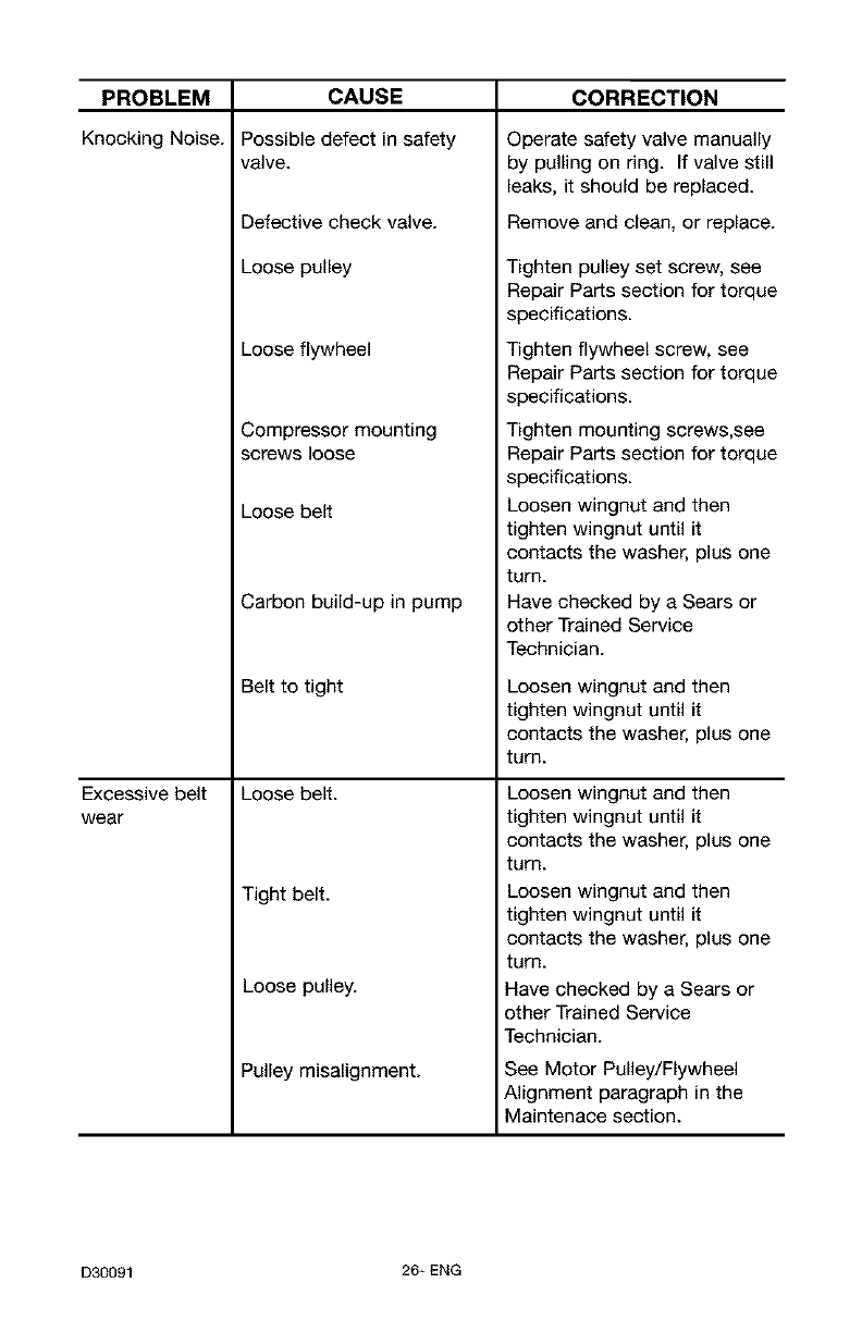
CAUSE
Possible defect in safety
valve.
PROBLEM
Knocking Noise.
Defective check valve.
Loose pulley
Loose flywheel
Compressor mounting
screws loose
Loose belt
Carbon build-up in pump
Excessive belt
wear
Belt to tight
Loose belt.
Tight belt.
Loose pulley.
Pulley misalignment.
CORRECTION
Operate safety valve manually
by pulling on ring. If valve still
leaks, it should be replaced.
Remove and clean, or replace.
Tighten pulley set screw, see
Repair Parts section for torque
specifications.
Tighten flywheel screw, see
Repair Parts section for torque
specifications.
Tighten mounting screws,see
Repair Parts section for torque
specifications.
Loosen wingnut and then
tighten wingnut until it
contacts the washer, plus one
turn.
Have checked by a Sears or
other Trained Service
Technician.
Loosen wingnut and then
tighten wingnut untilit
contacts the washe£ plus one
turn.
Loosen wingnut and then
tighten wingnut untilit
contacts the washe£ plus one
turn.
Loosen wingnut and then
tighten wingnut untilit
contacts the washe£ plus one
turn.
Have checked by a Sears or
other Trained Service
Technician.
See Motor Pulley/Flywheel
Alignment paragraph in the
Maintenace section.
D30091 26_ ENG
27-ENG D30091
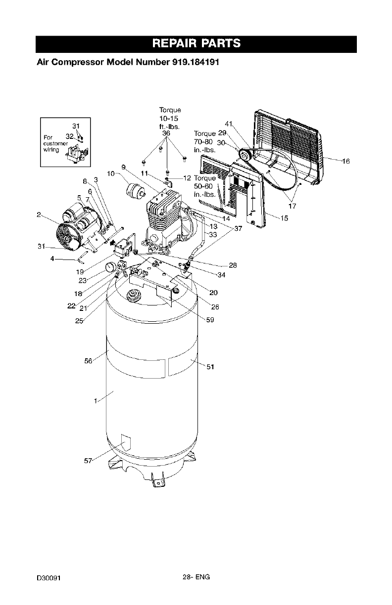
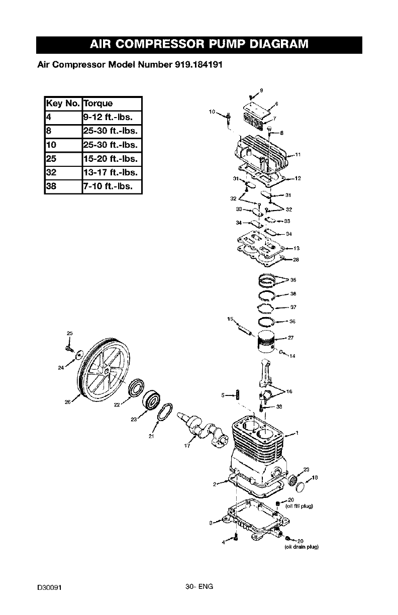
Air Compressor Model Number 919.184191
s6j
lJ
57j
Torque
10_15
ft.qbs,
36
414
Torque 29_
70_80
17
D30091 28_ ENG
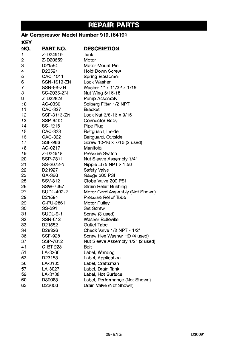
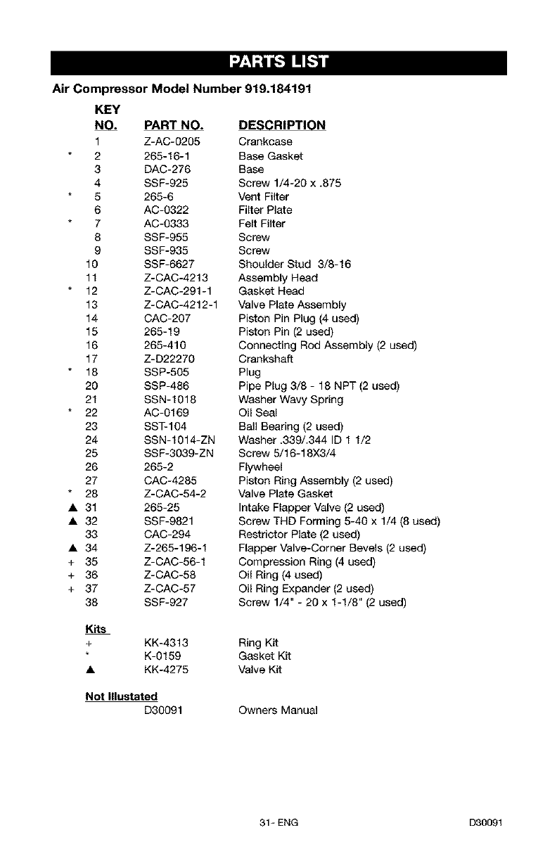
Air Compressor Model Number 919.184191
KEY
NO. PART NO. DESCRIPTION
1 Z-D24919 Tank
2 Z-D20659 Motor
3 D21594 Motor Mount Pin
4 D23591 Hold Down Screw
5 CAC-1011 Spring Elastomer
6 SSN-1619-ZN Lock Washer
7 SSN-56-ZN Washer 1" x 11/32 x 1/16
8 SS-2038-ZN Nut Wing 5/16-18
9 Z-D22624 Pump Assembly
10 AC-0330 Solberg Filter 1/2 NPT
11 CAC-327 Bracket
12 SSF-8113-ZN Lock Nut 3/8-16 x 9/16
13 SSP-9401 Connector Body
14 SS-1215 Pipe Plug
15 CAC-323 Beltguard, Inside
16 CAC-322 Beltguard, Outside
17 SSF-986 Screw 10-16 x 7/16 (2 used)
18 AC-0217 Manifold
19 Z-D24918 Pressure Switch
20 SSP-7811 Nut Sleeve Assembly 1/4"
21 SS-2072-1 Nipple .375 NPT x 1.50
22 D21927 Safety Valve
23 GA-360 Gauge 300 PSI
25 SSV-812 Globe Valve 200 PSI
26 SSW-7367 Strain Relief Bushing
27 SUDL-4O2-2 Motor Cord Assembly (Not Shown)
28 D21584 Pressure Relief Tube
29 C-PU-2861 Motor Pulley
30 SS-391 Set Screw
31 SUDL-9-1 Screw (3 used)
32 SSN-613 Washer Belleville
33 D21582 Outlet Tube
34 D28826 Check Valve 1/2 NPT- 1/2"
36 SSF-928 Screw Hex Washer HD (4 used)
37 SSP-7812 Nut Sleeve Assembly 1/2" (2 used)
41 C-BT-223 Belt
51 LA-3266 Label, Warning
53 D23153 Label, Application
56 LA-3105 Label, Craftsman
57 LA-3027 Label, Drain Tank
59 LA-3108 Label, Hot Surface
60 D30083 Label, Performance (Not Shown)
63 D23000 Drain Valve (Not Shown)
29_ ENG D30091
Air Compressor Model Number 919.184191
Key No. Torque
4 9-12 ft.-Ibs.
8 25-30 ft.-Ibs.
10 25-30 ft.-Ibs.
25 15-20 ft.-Ibs.
32 13-17 ft.-Ibs.
38 7-10 ft.-Ibs.
9
25
35
_37
21
!7
(oil drainm;lug)
D30091 30+ ENG
Air Compressor Model Number 919.184191
KEY
NO. PART NO.
1 Z-AC-02O5
2 265-16-1
3 DAC-276
4 SSF-925
5 265-6
6 AC-0322
7 AC-0333
8 SSF-955
9 SSF-935
10 SSF-6627
11 Z-CAC-4213
12 Z-CAC-291-1
13 Z-CAC-4212-1
14 CAC-207
15 265-19
16 265-410
17 Z-D22270
18 SSP-505
20 SSP-486
21 SSN-1018
22 AC-0169
23 SST-104
24 SSN-1014-ZN
25 SSF-3039-ZN
26 265-2
27 CA0-4285
28 Z-CAC-54-2
• 31 265-25
• 32 SSF-9821
33 CAC-294
• 34 Z-265-196-1
+ 35 Z-CAC-56-1
+ 36 Z-CAC-58
+ 37 Z-CAC-57
38 SSF-927
DESCRIPTION
Crankcase
Base Gasket
Base
Screw 1/4-20 x ,875
Vent Filter
Filter Plate
Felt Filter
Screw
Screw
Shoulder Stud 3/3-16
Assembly Head
Gasket Head
Valve Plate Assembly
Piston Pin Plug (4 used)
Piston Pin (2 used)
Connecting Rod Assembly (2 used)
Crankshaft
Plug
Pipe Plug 3/8 - 18 NPT (2 used)
Washer Wavy Spring
Oil Seal
Ball Bearing (2 used)
Washer .339/.344 ID 1 1/2
Screw 5/16-18X3/4
Flywheel
Piston Ring Assembly (2 used)
Valve Plate Gasket
Intake Flapper Valve (2 used)
Screw THD Forming 5-40 x 1/4 (8 used)
Restrietor Plate (2 used)
Flapper Valve-Corner Bevels (2 used)
Compression Ring (4 used)
Oil Ring (4 used)
Oil Ring Expander (2 used)
Screw 1/4" - 20 x 1-1/8" (2 used)
Kits
+KK-4313
K-0159
KK-4275
Ring Kit
Gasket Kit
Valve Kit
Not Illeetated
D30091 Owne_ Manual
31_ ENG D30091
GARANT|A ........................................... 32
CUADRO DE ESPECIFICACIONES ...................................... 33
DEFINICIONES DE NORMAS DE SEGURIDAD ............................. 33
IMPORTANTES INSTRUCCIONES DE SEGURIDAD ...................... 33-38
GLOSARIO .......................................................... 39
ACCESORIOS ....................................................... 39
CICLO DE SERVICIO .................................................. 39
ENSAMBLADO ....................................................... 40
INSTALACION ..................................................... 41-43
OPERACION ...................................................... 44-46
MANTENIMIENTO ................................................. 47-49
SERVICIOS Y REGULACIONES ...................................... 50-51
ALMACENAJE ....................................................... 52
GU(A DE DIAGNOSTICO DE PROBLEMAS ............................. 53-56
NOTES/NOTAS .................................................... 87-58
CONTRATOS DE PROTECCION PARA REPARACIONES ..................... 59
LISTA DE PARTES ................................................. 28-31
COMO SOLICITAR PIEZAS PARA REPARACION .................... contratapa
GARANT|A TOTAL DE UN AI_IO DEL COMPRESOR DE AIRE
Si este compresor de aire Craftsman fallase debido a defectos de materiales
ode fabricaci6n dentro del aSo de su fecha de compra, Sears, a su opei6n, Io
reparar& o reemplazar& sin eosto alguno. Comuniquese con el Centro de
Servicio Sears m&s cercano (1-800-4-MY-HOME) para coordinar su
reparaci6n, o devuelva el compresor de aire al lugar donde Io compr6 para
que Io cambien.
Si este compresor de aire se usase con fines comerciales o para alquiler, esta
garantia se aplica s61o durante los primeros noventa dias a partir de su fecha
de compra.
Esta garantia le otorga derechos especfficos y usted podrfa tener otros
derechos que varian de un estado a otto.
Sears, Roebuck and Co., Dept. 817WA, Hoffman Estates, IL 60179
D30091 32_ SP
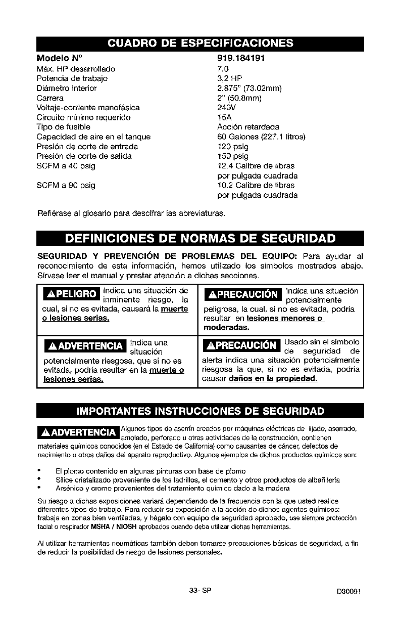
Modelo N°
Max. HP desarrollado
Potencia de trabajo
Di&metro interior
Carrera
Voltaje-corriente manofAsica
Circuito mfnimo requerido
Tipo de fusible
Capacidad de sire en el tanque
Presi6n de eorte de entrada
Presi6n de corte de salida
SCFM a 40 psig
SCFM a 90 psig
919.184191
7,0
3,2 HP
2.875" (73.02mm)
2" (50.8mm)
240V
15A
Accion retardada
60 Galones (227.1 Iitros)
120 psig
150 psig
12.4 Calibre de Iibras
pot pulgada cuadrada
10.2 Calibre de Iibras
pot pulgada cuadrada
Refierase al glosario para descifrar las abreviaturas.
SEGURIDAD Y PREVENCION DE PROBLEMAS DEL EQUIPO: Para ayudar al
reconocimiento de esta informaci6n, hemos utilizado los sfmbolos mostrados abajo.
Sirvase leer el manual y prestar atenci6n a dichas secciones.
_ Indicauna situaci6nde
inminente riesgo, la
cual, si no es evitada, causara la muerte
olesionee series.
potencialmente riesgosa, que si no es
evitada, podrfa resultar en la muerte o
lesiones serias,
_ Indies una situaci6n
potencialmente
peligrosa, la cual, si no es evitada, podria
resultar en lesiones menores o
moderades.
_ Usado sin el sfmbolo
de seguridad de
alerts indica una situacion potencialmente
riesgosa la que, si no es evitada, podria
causar da_os en le propiedad.
IIlv_I _o] :i L't_i t=[--__[l_,[-._l[((o_ ID1_ [._€-!1 ] i1117,.Ii)
_ Algunos tipos de aserr[n cresdos pot m&quinas electricas de Iijado, sserrado,
3motsdo, perforado u otras actividades de Is construcci6n, contienen
materiales qu_micos conocidos (en el Estado de California) como causantes de c&ncer, defectos de
nacimiento u otros d_os del aparato reproductivo. A_gunos ejemplos de dichos productos quimicos son:
El plomo contenido en algunas pinturas con base de plomo
Sflice cristalizado proveniente de los ladrillos, el cemento y otros productos de albaSilerfa
Ars6nioo y oromo provenientes del tr_tamiento qufmico dado a la readers
Su r_esgo a dichas exposiciones variar& dependiendo de la frecuencia con la que usted realice
diferentes tipos de trabajo. Pars reducir su exposici6n a la acci6n de dichos agentes quimicos:
trabaje en zonas bien ventiladas+ y h&galo con equipo de seguridad aprobado, use siempre protecci6n
facial o respirader MSHA /NIOSH aprobados cuande deba utilizar dichas herramientas.
AI utilizar herramientas neum&tioas tambi_n deben tomarse precauciones bAsicas de seguridad, a fin
de reducir la posibilidad de riesgo de lesiones personales.
33- SP D30091
GUARDE ESTAS INSTRUCCIONES
La operaciSn o el mantenimiento inadecuados de este producto podrian ocasionar
serias lesiones y dafios a la propiedad. Lea y comprenda todas las advertencias e
instrucciones de funcionamiento antes de utilizar este equipo.
',]=lm[_ ;{_
ADVERTENCIA: Riesgo de Explosi6n o Incendio
qud puede occurrir
Para los contaotos el_ctricos es normal la
existencia de chispas entre el motor yel
intermptor a presi6n.
Si Ias chispas el_=ctricas provenientes d_
compresor tomaran contacto con
emanaciones de materiales inflamables,
ellos podrian arder originando incendio o
explosibn.
Restringir cualquiera de las aberturas de
ventilacibn causar_ un serio recalentamiento
y podrla producir un incendio.
Dejar desatenido este producto mientras el
mismo est& en funcionamiento puede
resultar en lesiones personales oda_os a la
propiedad= Para reducir el riesgo de
incendio, no permita que el oompresor
opere desatendido.
cbmo prevenirlo
Opere siempre el compresor en un sector
bien ventilado y libre de materiales
combustibles, gasolina o emanaciones de
solvente=
En un &tea de rociado de materiales
infiamables, ubique al compresor por Io
menos a 6,1m (20 pies) de distancia del _rea
de rociado. Podrla requerirse una extensi6n de
la manguera.
Almacene los materiales inflamables en una
ubicaci6n segura, alejados del compreson
Jamds coloque objetos apoyados o sobre el
compresor. Opere el compresor en un sector
abierto, por Io menos a 30 cm (12 pulgadas)
alejado de cualquier pared u obstrucci6n que
restrinja el flujo de aim fresco alas aberturas de
ventilaci6n.
Opere el compresor en un sector limpio, seco, y
bien ventilado. NO opere la unidad en espacios
cerrados o cualquier drea confinada.
Mant_ngase siempre alerLa cada vez que el
_roducto este funcionando.
Desconecte siempre el suministro el_ctrico
moviendo la palanca conmutadora de
presi6n a la posici6n de apagado (off), y
drene el tanque diariamente o despu{_s de
cada uso=
D30091 34- SP
'J=Ira[_ r,{q
ADVERTENCIA: Riesgo de Explosi6n
Tanque de aire: las siguientes condiciones podrian, causar el debilitamiento del tanque, y
determinar su explosion violenta, daSos a la propiedad o serias lesiones.
qud puede occurrir cbmo prevenido
Drenaje inadecuado del agua condensada Drene el tanque diariamente o despu_s de
en el tanque, siendo la causa del 6xido que cada uso. Si et tanque genera una perdida,
reduce el espesor del tanque de acero, reemplbcelo inmediatamenta con un nuevo
tanque o reemplace el compresor completo.
Modificaciones o intento de reparaciones Jam_s perfore, suelde, o efectde modificacibn
al tanque, alguna al tanque o sus accesorios.
Modificaciones no autorizadas ala v_lvula
de descarga, vblvula de seguridad o
cualquier otto componente que controle la
presibn del tanque.
La vibraci6n excesiva puede debilitar el El t_qque est_ dise_ado para resistir presiones
tanque de aire y causar su ruptura o operativas espeolficas. Jambs efectde ajustes
explosibn, o sustituya partes que alteren las
regulaciones de presibn originales de
fbbrica.
AGREGADOS Y ACCESORIOS
El exceso a los valores de presibn
establecidos para las herramientas
neun'_ticas, pistolas rociadoras, accesorios
activados pot aire, cubiertas y otros objetos
inflables, puede causar su explosi6n o set
arrojados, pudiendo ocasionar serias lesiones.
Para un control esencial de la presi6n, debe
usted instalar un regulader y un medidor de
presi6n ala salida del aire de su compresor. (Si
no estuviese equipado) Siga las recomendaciones
de los fabricantes de su equipo y jambs exceda
los valores m&ximos de presibn permitidos p_ra
los acc_orios, Jamds use el compresor para
inflar ob'tetcs que requieren poca o baja
presibn, tales como juguetas para los nitros,
pelotas de f(itbol, pelotas de basquet, etc.
'J=l=l[d r,{q
ADVERTENCIA: Riesgo de Objetos Arrojados pot el Aire
qu_ puede occurrir cbmo prevenido
El chorro de aire comprimido puede causar
da_os sobre los tejidos blandos de la piel
expuesta, y puede propulsar suciedad,
astiIlas, partlculas sueltas y pequeSos objetos a
aka velocidad, ocasi0nando da_os a la
propiedad o lesiones personales.
AI utilizar el compresor, use siempre anteojos
de seguridad ANSI Z87.1 aprobados, con
protecci6n lateral.
Jamds apunte ninguna boquilla o
pulverizador hacia parses del cuerpo, a otras
personas o
animales.
Apague siempre el compresor y purgue la
presibn de la manguera del aire y deI tanque,
antes de intentar eI mantenimiento, el acople
de herramientas o accesorios.
35- SP D30091
•,,l::1nnl[_1r,{q
ADVERTENCIA: Riesgo de Descatga Eldctrica _/F
qud puede occurrir cbmo prevenirlo
Su compresor de aire estA accionado pc# Jam_s opere el compresor a la intemperie
electricidad, Como cua_quier otto dispositivo cuando est& Iloviendo o en condiciones de
el_ctrico imputsado et6ctricamente, si no se Io humedad,
utiliza adecuadamente, podria causarle una Nunca opere el compresor sin sus defensas o
descarga el_ctrica, sus cubiertas removidas o da_adas.
Las reparaciones intentadas pot personal Cualqu+er conexibn el_ctrica o _eparaci6n
no calificado podrian ocasionar serias requerida pot este producto debe ser
$esiones o la muerte por electrocuci6n, efectuada pot personal autorizado de los
servicentros de acuerdo a los c6d+gos
el_ctricos nacionales y locales.
CONEXI(_N A TIERRA: Dejar de proveer una Asegt_rese que el circuito el_ctrico al cual
adecuada cormxibn a tierra a este producto est& conectado el compresor, suministra
pedria ccasionar lesiones serias o la muerte apropiada conexibn a tierra, tensi6n correcta
por electrocuci6n= Vet instrucciones para la y una adecuada protecci6n de fusibles.
puesta a tierra.
p,.]:4unlIt1:To]
ADVERTENCIA: Riesgo de Inhalaci6n
qud puede occurrir cbmo prevenirlo
E_aire comprimido proveniente del compresor
no es sano para respirar. El chorro de aire
puede contener mon6xido de carbono,
vapores t6xicos o partlculas sblidas
provenie_es del tanque. La inhalaci6n de
dichos contaminantes peede Uegar a causar
serias lesiones o la muerte=
El tociado de materiates tales como pintura,
solventes, removedores de pintura,
insecticidas, mata hierbas, contienen
emanaciones da_inas y venenosas,
E_aire obtenido directamente del compresor
am_is deberd ser utilizado para proveer aim
_ara consumo humano. Para poder utilizar el
aire producido por este compresor y hacerlo
respirable, deber_in instalarse un filtro
adecuado yun equipe de seguridad
intercalado= Los filtros intercalados tanto como
el equipo de seguridad utilizado en conjunto
con el compresor, deber_n ser capaces de
}rocesar el tratamiento del aire de acuerdo a
todos los cbdigos locales y federales, previo
al consumo humano.
Trabaje en un &rea con buena ventilacibn
cruzada. Lea ysiga las instrucciones de
seguridad provistas en el r6tulo oen los datos
de las hojas de seguridad del material que est_
}ulverizando. Use el respirador aprobado
NIOSH/MSHA designado para utilizarse con su
8plicaciSn especffica,
D30091 36+ SP
_=ll[_r,{w
ADVERTENCIA: Riesgo de Quemaduras
qu_ puede occurrir
Tooar el metal expuesto tal como el cabezsI
del compresor o los tubos de salida del
escape, puede ocasionarle serias
quemaduras.
cbmo prevenirlo
Jam_is toque partes de metal expuestas en el
compresor durante o inmedistamente despu_s
de la operaci6n, el compresor permanecer_
caliente pot varios minutos luego de la
operaci6n.
No Io cubra con fundas protectoras o intente el
mantenimiento hasta que la unidad haya
alcanzado su enfriamiento.
_=ll[_r,{w
ADVERTENCIA: Riesgo de Partes Mbviles
que puede occurrir cbmo prevenirlo
Partes movibles tales come Ia pole& el Nunca opere el compresor sin sus defensas
volante y la correa podrlan ser la causa de o sus cubiertas removidas o da_adas.
serias lesiones si elias entraran en contacto
con usted o sus ropas.
Intentar operar el compresor con sus Cualquier reparaci6n requerida pot este
partes da_adas o faitantes, o la reparacibn producto debe ser efectuada pot personal
del compresor con sus protecciones autorizado de los servicentros.
removidas, puede exponerlo a usted a
partes movibles, que podrlan resultar en
lesiones serias=
#=ll [_ r,{,,
ADVERTENCIA: Riesgo de Caida _
qu_ Duede occurrir cbmo orevenirlo
Un compresor port&til puede caerse de la
mesa, el banco de trabs_o o del techo da_ando
al compresor ypudiendo resultar en serias
lesiones o la muerte del operador=
Opere siempre el compresor en una posici6n
estable y segura afin de prevenir el
movimiento accidental de la unidad. Jam_s
opere el compresor sobre un techo u otra
posicibn elevada. Utilice mangueras
adicionales de aire para alcanzar posiciones
altas.
37_ SP D30091
',1=1! It-1;{_
ADVERTENCIA: Riesgo de Serias Lesiones o Da_os a la Propiedad al
Transportar el Compresor
(Fuego, inhalaci6n, da_o ala superficie de vehiculos)
qud puede occutrit cbmo prevenirlo
El aceite puede derramarse y ello podrfa Deposite el compresor sobre una alfombrilla
resuttar en serias les+ones o la muerte debido protectora cuando Io transporte, a fin de
al riesgo de incendio o inhalaciSn. E_derrame proteger al vehiculo de p_rdides pot goteo,
de aceite daSa atfombras, pinturas u otras Retire el compresor del vehiculo
superf+cies de vehiculos o remotques, inmediatamente despu_s de su arribo al
destino.
ADVERTENCIA: Riesgo de Operaci6n Lasegura A
qud puede occurrir cbmo prevenirlo
La operation insegura de su compresor de
aire podrla ocasionarle serias lesiones ola
muerte austed u otros.
Revise y comprenda todas las instrucciones y
advertencias contenidas en este manual.
Familiar_cese con los m_todos de operacibn
y control del compresor de aire.
Mantenga libre la zona de eperaciones de
persona 8Jguna+ animates dom_sticos y
obst&culos.
ianter_ga aEejados a los ni_os de{ compresor
de aire en todo memento.
No opere el producto cuando se encuentre
fatigado o bajo la influencia del alcohol o
drogas. Est_ alerta en todo memento.
Jam_is altere los elementos de seguridad de
este producto.
Equipe la zona de operaciones con un
extinguidor de fuego.
No opere la mdquina si _sta tiene parses
faltantes, rotas o no autorizadas.
CONSERVAR ESTAS INSTRUCCIONES
D30091 38 + SP
Familiadcese con los siguiantes t_rminos,
antes de operar la unidad:
OFM: (Cubic feet per minute) Pies cQbicos
por minuto.
SCFM: (Stardard cubic feet per minute)
Pies ct_bicos est&ndar pot minuto; una
unidad de medida que permite medir la
cantidad de entrega de aire.
PSIG: (Pound per square inch) Libras por
pulgada cuadrada.
Obdigo de eertificaoi6n: Los productos
que usan ana o m&s de las siguientes
marcas: UL, CUL, ETL, CETL, hen sido
evaluados por OSHA, laboratorios
independientes certificados en seguridad,
y reunen los est&ndares suscriptos per los
laboratorios dedicados ala certificaci6n
de la seguridad.
Presibn minima de corte: Cuando el
motor est& apagado, la presi6n del tanque
de aire baja a medida que usted contint_a
usando su accesorio Cuando la presi6n
del tanque baja al valor fijado an f&brica
como punto bajo, el motor volver& a
arrancar autom&ticamante. La presion
baja a la cual el motor arranca
autom&ticamente, se llama presion
"minima de corte".
Presi6n m_xima de corte: Cuando un
compresor de aire se enciende y
comienza a funcionar, la presi6n de aire
en el tanque comianza a anmentar.
Aumanta haste un valor de presi6n alto
fijado en f&brica antes de que el motor
autom&ticamente se apague protegiando
a su tanque de aire de presiones m&s
altas que su capacidad. La presi6n atta a
la cual el motor seapaga se llama presi6n
"m&xima de "corte".
Ramal: Circuito electrico que transporta
electricidad desde el panel de control
haste el tomacorriente.
Esta unidad ss suficiente para ebastecer de energie electdca ales siguientss acceserios. Estos se
encuentran dispenibles a traves del cat&logo pare herrernientas electrices y manuales, en
cualquiera de los comercios que mantiene la linea complete de SEARS.
Accesorios
• Filtro en linea
• Entrada de aire a neum&ticos
• Juegos de conectores r&pidos (varios
tama_os)
• Reguladores de presion de aire
• Lubricadores de niebla de aceite
• Manguera de aire:
1/4", 5/16",3/8" o 1/2" D.L en varias
medidas
[o,][_o31 m]=1_o,] [o]
Esta bomba compresora de aire es capaz
de faneionar continuamante, sin embargo
para prolongar la vida t_til de su
compresor de aire se recomienda
mantener un ciclo promedio de servicio
que oscile entre el 50% y el 75%; ello
significa que la bomba compresora no
deberia trabajar m_s de 30 a 45 minutos
pot hora.
39* SP D30091
Herramientas requeridas para el
Ensamblado
1 - Uave de tubo 9/16" o llave mec&nica
de boca abierta
1 - Taladro electrico
Desembalaje
I. Extraiga todo el embalaje
Podrd ser
necesado apuntalar
o soportar un lado del equipo al extraer
la plataforma, porque el compresor de
aire tendera a inclinarse.
2. Extraiga y descarte los (4) tomillos y
arandelas qua sujetan el compresor a
la plataforma.
3, Con la ayuda de otra persona,
remueva cuidadosamente el
compresor de aire de su plataforma y
colSquelo sobre una plataforma
nivelada.
Para agregar aceite a la bomba
Los compresores
se envian sin
aceite. AI tecibir el compresor de aire,
puede haber un poco de aceite en la
bomba. Esto se debe a las pruebas en
la fabrica y no significa que la bomba
tiene aceite. No intentar operar este
compresor de aire sin antes haberle
agregado aceite al carter. Pueden
ocurrir serios dafios, inclusive con
opetaciones limitadas, si no se Ilena de
aceite y no se asienta correctamente.
Cercioratse de seguir cuidadosamente
los procedimientos pata el arranque
iniciaL
No se deben usar
aceites de
viscosidad mdltiple como 10W30 en
ningAn compresor de aire. Estos
aceites dejan depbsitos de catbono en
componentes criticos, reduciendo el
rendimiento y la vida Atil del compresor.
NOTA: Use aceite para compresor tipo
Sears, item 9-16426 6SAE-20 (API CG/CD)
de servicio pesado para motor. Para
condiciones extremas invemales use aceite
pesado SAE-10.
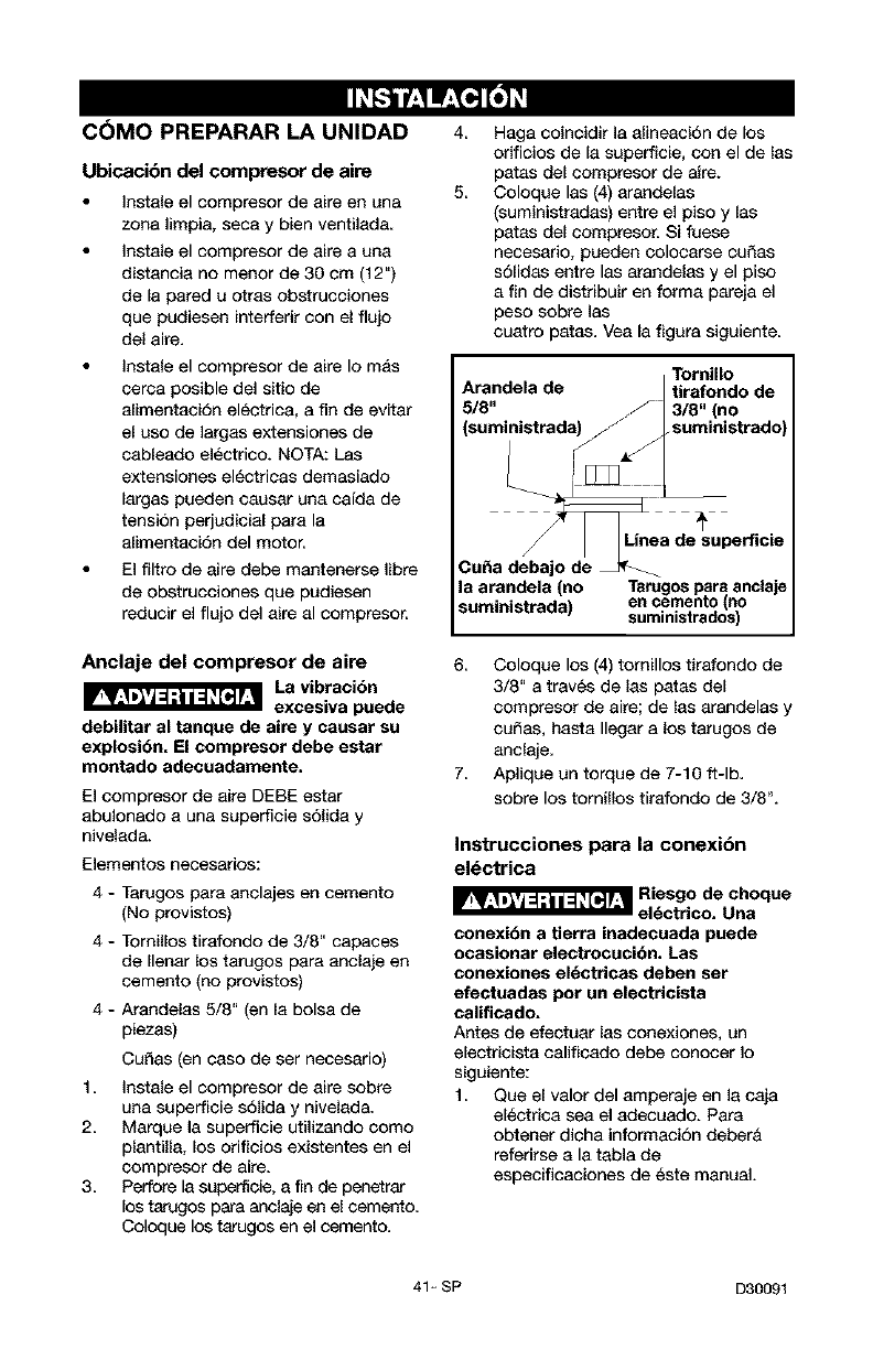
Aceite
Drene el tanque
fin de liberar la
presibn de aire antes de extraer la tapa
para el relleno de aceite, o el tapbn
para drenaje del aceite.
1. Colocar la unidad en una superficie
nivelada.
2, Extraiga el tap6n de aceite (A) y
agregue lentamente aceite para
compresor hasta qua quede a ras del
borde de[ orificio de Ilenado de
aceite. NOTA: No permita qua el
nivel de aceite Ilegue en ningQn
momento a 3/8" (6 filetes) del borde.
AI Ilenar el carter, el aceite fluye muy
lentamente. Si sele agrega aceite
muy rapido, el carter se rebalsara y
aparentara estar lieno.
NOT_ La capacidad del carter es de
16 onzas liquidas (473ml) de aceite.
3. Colocar la tapa de Ilenado de aceite.
D30091 40- SP
COMO PREPARAR LA UNIDAD
Ubicacibn del comp_sor de aire
Instale el compresor de aire en una
zona limpia, seca y bien ventilada.
Instale el compresor de aire a una
distancia no menor de 30 cm (12")
de la pared u otras obstrucciones
que pudiesen interferir con el flujo
del aire.
Instale el compresor de aire Io m_s
cerca posible del sitio de
alimentaciSn electrica, a fin de evitar
el uso de largas extensiones de
cableado electrico. NOTA: Lss
extensiones electricas demasiado
largas pueden causar una cafda de
tension perjudicial para la
alimentaciSn del motor.
El filtro de aire debe mantenerse libre
de obstrucciones que pudiesen
reducir el flujo del aire al compresor.
Anclaje del compresor de aire
La vibracibn
excesiva puede
debilitar al tanque de aire y causar su
explosi6n. El comptesor debe estat
montado adecuadamente.
El compresor de aire DEBE estar
abulonado a una superficie s61ida y
nivelada.
Elementos necesarios:
4 - Tarugos para anclajes en cemento
(No provistos)
4 - Tornillos tirafondo de 3/8" capaces
de Ilenar los tarugos para anclaje an
cemento (no provistos)
4 - Arandelas 5/8" (en la bolsa de
piezas)
Cu_as (en caso de ser necesario)
1 Instale el compresor de aire sobre
una superficie s61ida y nivelada.
2. Marque la superficie utilizando como
plantilla, los orificios existentes en el
compresor de aire.
3. Perfore la superficie, a fin de penetrar
los tarugos para anclaje en el cemento.
Coloque los tarugos en el cemento.
4,
5.
Haga coincidir la alineacion de los
orificios de la superficie, con el de Ins
patas del compresor de aire.
Coloque las (4) arandelas
(suministradas) entre el piso y las
patas del compresor. Si fuese
necesario, pueden colocarse cu£_as
solidas entre Ins arandelas y el piso
a fin de distribuir en forma pareja el
peso sobre Ins
cuatro paras. Vea la figura siguiente.
Tornillo
Arandela de tirafondo de
5/8" 3/8" (no
suministrado
la atandela (no
suministrada)
Linea de superficie
Tarugos pars anclaje
en cemento no
sum n strados
6 Coloque los (4) tomillos tirafondo de
3/8" a traves de Ins patas del
compresor de aire; de Ins arandelas y
cu_as, hasta Ilegar a los tarugos de
anclaje.
7. Aplique un torque de 7-10 ft-lb.
sobre los tomiUos tirafondo de 3/8L
Instrucciones para la conexi6n
el_ctrica
_Rliestg2cde,h° que
conexibn a tierta inadecuada puede
ocasionar electrocucibn, Las
conexiones el_ctricas deben set
efectuadas pot un electticista
calificado.
Antes de efectuar las conexiones, un
electricista calificado debe conocer Io
siguiente:
1. Que el valor del amperaje en la caja
electrica sea el adecuado. Para
obtener dicha informacion debera
referirse a la tabla de
especificaciones de _ste manual.
41_ SP D30091
2 Que la linea de suministro electrico
tenga id6nticas caracteristicas
electricas (voltaje, ciclos, fases) que
las del motor. Para obtener dicha
informaci6n debera referirse a la
placa de identificaci6n del motor,
ubicada sobre el lateral del mismo.
NOTA: El voltaje suministrado debe ser
igual el voltaje indicado sobre la placa de
identificaci6n del motor m&s o menos
10%. Para informarse acerca de las
extensiones y calibres de cable
recomendadas y m&xima extensi6n del
circuito, deber& referirse a los c6digos
locales; un circuito subdimensionado
origina una caida elevada del amperaje y
un recalentamiento del motor.
e. e:;Oco,e .o,°e
eonexibn el_otrica debe estar ubieeda
fuera de superficies calientas, tales
como silenciadoree de escape, tubos
de salida de compreeotes de aire,
cabezalee o cilindros.
INSTRUCCIONES PARA
CONECTAR A TIERRA
Este artefacto debe conectarse al terminal
metalico de un sistema de cableado
permanente a tierra para equipos o al
terminal del artefacto<
La conexi6n a tierra est& claramente
indicada sobre el compresor<
Proteccibn del voltaje y del circuito
Acerca del voltaje y la minima cantidad de
circuitos requeridos, refi_rase al cuadro de
especificaciones.
_Riesgo de
Operacibn
Laseguta. Ciertos compresores de aire
pueden set operados en an citcuito de
15 A, siempte que se cumplan las
siguientes condiciones:
1. Que el voltaje suministrado a tray,s de
los ramales del circuito sea de 15 A.
2.
3<
Que el circuito no sea utilizado para
alimentar ninguna otra necesidad
electrica.
Que los cables de extension cumplan
con las especificaciones.
4 El circuito cuenta con un disyuntor
de 15 amperios o un fusible de
acci6n retardada de 15 amperios.
NOTA: Si el compresor esta
conectado a un circuito protegido
por fusibles, use s61o fusibles de
acci6n retardada. Los fusibles de
acci6n retardada deben estar
marcados con la tetra "D" en Canad&
y "T" en EE<UU.
Si cualquiera de las condiciones
enumeradas no pudiese set cumplida, o si
el funcionamiento del compresor causara
reiteradas interrupciones de la energfa con
la que se Io alimenta, podrfa ser necesario
operar al mismo desde un circuito de 20
A< Para clio no ser& necesario cambiar su
cable de limentaci6n<
Sistema de distribucibn de aire
Los tabos de
plastico o PVC
no hart sido dise_ados para usarlos con
aire comprimido. Independientamenta
de Io que estd indicado como
especificaci6n de ptesibn, las ce_etias
de plastico pueden explotat debido a la
presibn del aite. UtUice solamente
ca_os de metal pata los tamales de
disttibuci6n.
La siguiente imagen representa un
sistema tfpico de distribuci6n de aire. Las
siguientes son pautas para tener presente
al montar el sistema de distribucion del
compresor de aire.
Utilice caSo de la misma medida que
el de la salida del tanque de aire.
Una caSerfa demasiado angosta
restringir& el paso del aire<
Si la ca£_eria tiene m&s de 30 m
(100 pies) de Iongitud, utilice la
medida inmediata superior.
D30091 42_ SP
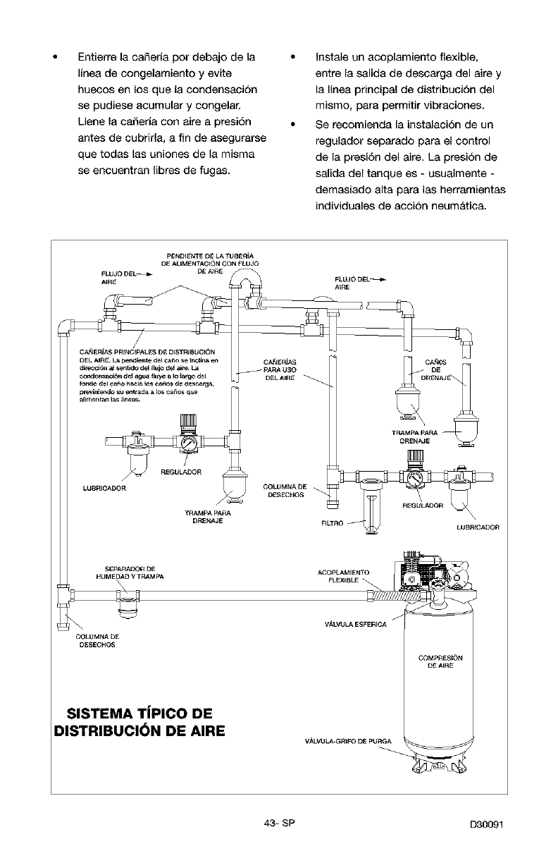
Entierre la ca_erfa pot debajo de la
Ifnea de congelamiento y evite
huecos en los que la condensaci6n
se pudiese acumular y congelar.
Llene la ca_eria con aire a presi6n
antes de cubrirla, a fin de asegurarse
que todas las uniones de la misma
se encuentran libres de fugas.
Instale an acoplamiento flexible,
entre la salida de descarga del aire y
la linea principal de distribuci6n del
mismo, para permitir vibraeiones.
Se reeomienda la instalaei6n de un
regulador separado para el control
de la presi6n del aire. La presi6n de
salida del tanque es - usualmente -
demasiado alta para las herramientas
individuales de accion neum&tica.
FLUJO D_L_ DE AIRE
._RE
OA_ERIA$ p RINCIPAt.ES DE DiSTRiBUCION
DEL AIR_ £_ pe_d_n_e del ¢_o se _nclit_ e_
_irec_i_n al se_udo dei _UiO deJ aJte_La
_o_ensaci6n det agua _uye _ I_ _rgo del
f_o del _o ha_ _ C_o_ de de_eatga_
previnie_ _ em_ad_ a_0¢_os _ue
_meman _as_eas_
LU_IOADOR
TRAMPA pARA
DR_NA_E
p_NDI_N_2_ D_ LA TUBERiA
DE AiJMENTAOION CON FLUJO
FLUJO D_L_
A_RE
_TRAMpA PAVIA
0ADOR
SEpARADOR DE
HUMEDAD y TRAMPA
\
COLUMNA DE
DESECHC_
SISTEMA TiPICO DE
DISTRIBUCI_)N DE AIRE
VALVOLA ESFERIG A /
V._V_ LA_GR_FO DE PURGA
COMPRE_ON
OE AIRE
43- SP D3009t
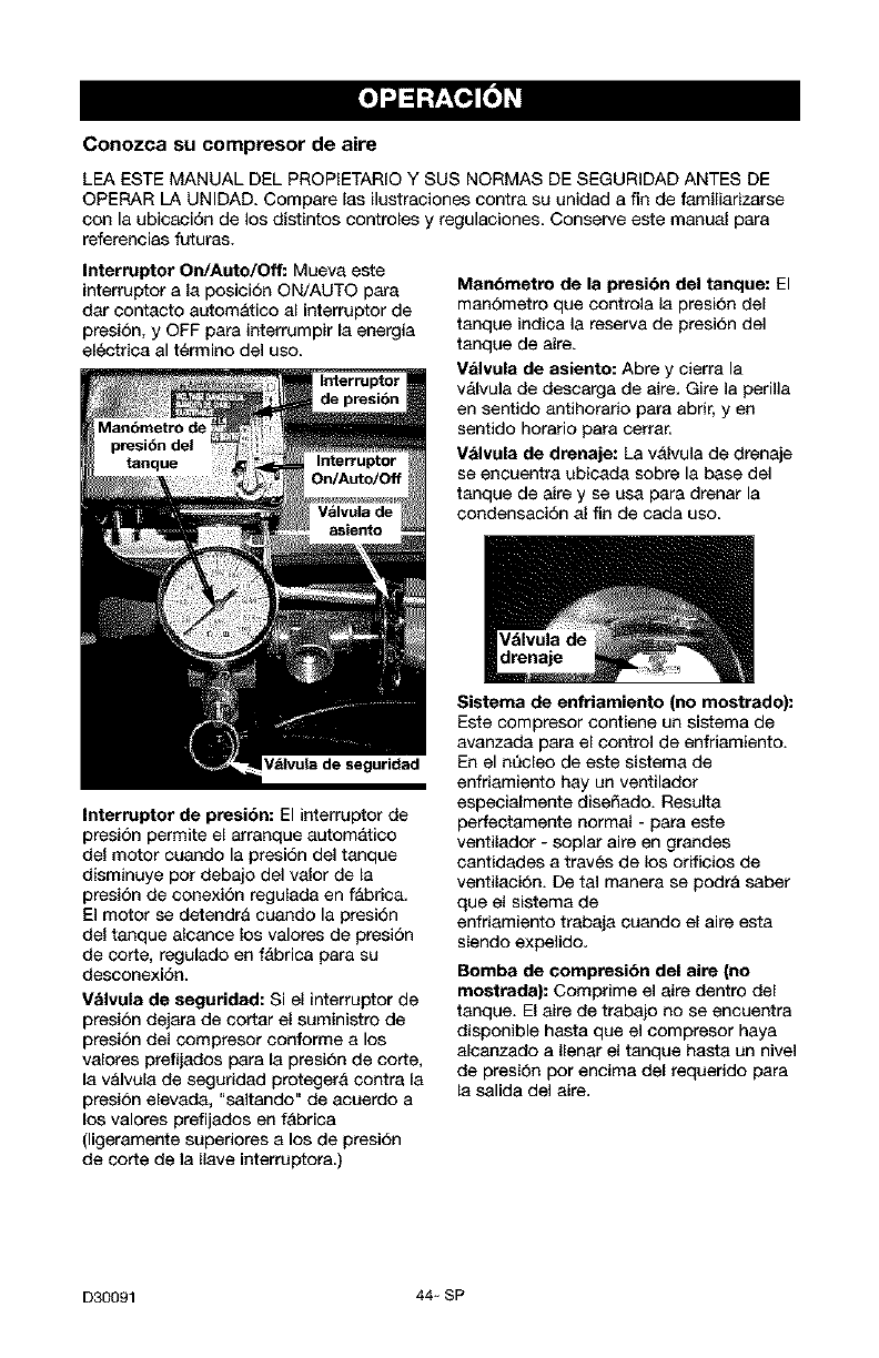
Conozca su compresor de aire
LEA ESTE MANUAL DEL PROPIETARIO Y SUS NORMAS DE SEGURIDAD ANTES DE
OPERAR LA UNIDAD, Compare las ilustraciones contra su unidad a fin de familiarizarse
con la ubicaci6n de los distintos controles y regulaciones Conserve este manual para
referencias futuras.
Interruptor On/Auto/Off: Mueva este
interruptor a la posici6n ON/AUTO para
dar contacto autom&tico al interruptor de
presion, y OFF para interrumpir la energia
electrica al t_rmino del uso.
p_si6n del
_nque
Interruptor
de presi6n
Intertuptor de presidn: El interruptor de
presi6n permite el arranque automatico
del motor cuando la presi6n del tanque
disminuye por debajo del valor de la
presi6n de conexi6n regulada en f&bric&
El motor se detendr& cuando la presi6n
del tanque alcanee los valores de presi6n
de corte, regulado en f_brica para su
desconexi6n.
Valvula de segutidad: Si el interruptor de
presi6n dejara de cortar el suministro de
presi6n del compresor conforme a los
valores prefijados para la presi6n de corte,
la v&lvula de seguridad protegera contra la
presi6n elevada, "saltando" de acuerdo a
los valores prefijados en fabrica
(ligeramente supedores a los de presi6n
de corte de la Ilave interruptora.)
Man6metro de la ptesibn del tenque: El
man6metro que controla la presi6n del
tanque indiea la reserva de presi6n del
tanque de aire.
Valvula de asiento: Abre y cierra la
valvula de descarga de aire. Gire la perilla
en sentido antihorario para abrir, yen
sentido horatio para cerrar.
Valvula de dreaaje: La valvula de drenaje
se encuentra ubicada sobre la base del
tanque de aire y se usa para drenar la
condensaci6n al fin de cada uso.
Valvula de
drenaje
Sistema de enfriamiento (no mostrado):
Este compresor contiene un sistema de
avanzada para el control de enfriamiento.
En el nQeleo de este sistema de
enfriamiento hay un ventilador
especialmente disefiado. Resulta
perfectamente normal - para este
ventilador - soplar aire en grandes
cantidades a traves de los orificios de
ventilaci6n. De tal manera se podr& saber
que el sistema de
enfriamiento trabaja cuando el aire esta
siendo expelido.
Bomba de compresi6n del aire (no
mostrada): Comprime el aire dentro del
tanque. El aire de trabajo no se encuentra
disponible hasta que el compresor haya
alcanzado a Ilenar el tanque hasta un nivel
de presi6n por encima del requerido para
la salida del aire,
D30091 44- SP
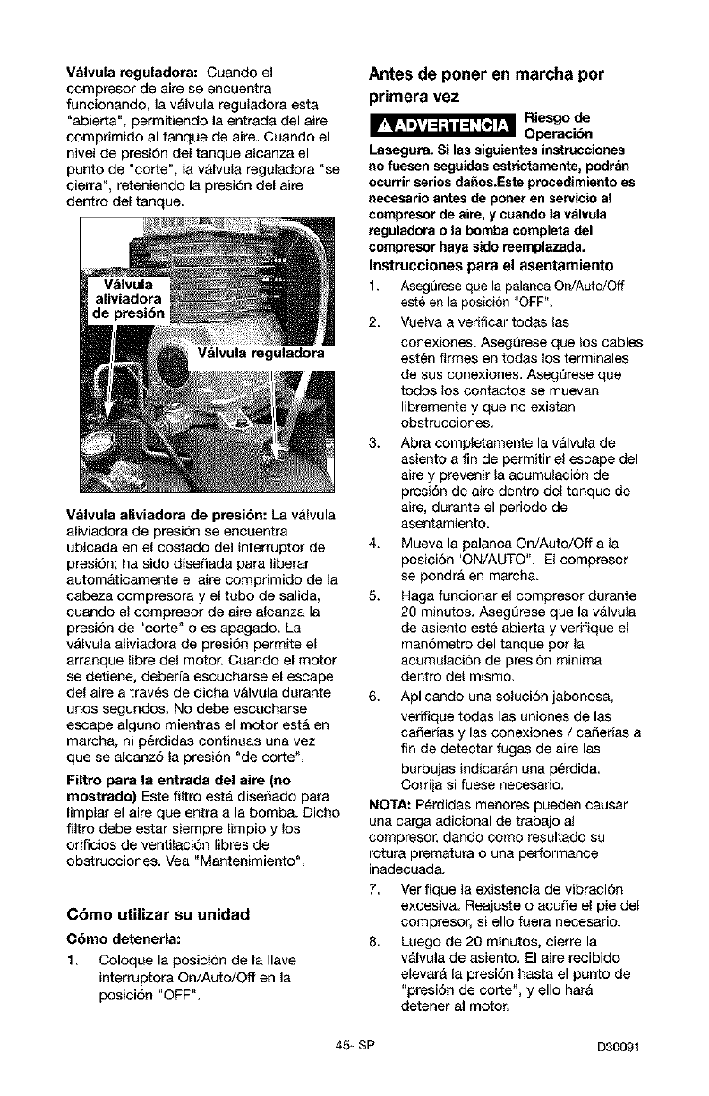
Valvula reguladora: Cuando el
compresor de airs se encuentra
funcionando, la valvula reguladora esta
"abierta", permitiendo la entrada del airs
comprimido al tanque de aire. Cuando el
nivel de presi6n del tanque alcanza el
punto de "corte", la valvula reguladora "se
cierre", reteniendo la presi6n del airs
dentro del tanque.
de presi6n
uladora
Valvula aliviadora de presidn: La v_lvula
aliviadora de presi6n se encaentra
ubiceda en el costado del interruptor de
presi6n; ha sido disefiada para liberar
autom&ticamente el airs comprimido de la
cabeza compresora y el tabo de salida,
cuando el compresor de airs alcanza la
presi6n de "corte" o es apagado. La
v_lvula aliviadora de presi6n permits el
arranque libre del motor. Cuando el motor
se detiene, deberfa eseucharse el escape
del aire a treves de dicha v&lvula durente
unos segundos. No debe escucbarse
escape alguno mientras el motor est& en
marcba, ni p_rdidas continuas una vez
que se alcanz6 la presi6n "de corte%
Filtro para la entrada del aire (no
mostrado) Este filtro est& diseSado para
limpiar el airs que entra a la bomba. Dicho
filtro debe estar siempre Iimpio y los
orificios de ventilaci6n Iibres de
obstrucciones. Vea "Mantenimiento%
Cbmo utilizar su unidad
Cdmo detenerla:
1. Coloque la posici6n de la liars
interruptora On/Auto/Off en la
posici6n "OFF".
Antes de poner en marcha por
primera vez
_Riesgo de
Opemci6n
Lasegura. Si las sigeientes instrucciones
no fuesen segeidas estrictamente, podran
ocurrir serios dahos.Este procedimiento es
necesario antes de porter en servicio al
compresor de sire, y euando la valvela
reguladora e la bomba completa del
compresor hays sido reemplazada.
Instrucciones para el asentamiento
1. Aseg0rese qLISla palanca On/Auto/Off
est6 en la pesici6n "OFF".
2. Vuelva a verificar todas las
conexiones. Aseg0rese que los cables
est_n firmes en todas los terminales
de sus conexiones. Aseg0rese que
todos los eontactos se muevan
libremente y que no existan
obstruceiones.
3. Abra completamente la v&lvula de
asiento a fin de permitir el escape del
aire y prevenir la acumulacion de
presi6n de aire dentro del tanque de
aire, durante el periodo de
asentamiento.
4. Mueva la palanca On/Auto/Off a la
posiei6n 'ON/AUTO". El compresor
se pondra en marcha.
5. Haga funcionar el compresor durante
20 minutos. Aseg_rese que la v&lvula
de asiento este abierta y verifique el
man6metro del tanque pot la
acumulaei6n de presi6n minima
dentro del mismo.
6. Aplicando una soluci6n jabenosa,
verifique todas las uniones de las
cafierias y las conexiones /caSerias a
fin de detectar fugas de airs las
burbujas indicar&n una p_rdida.
Corrija si fuese necesario.
NOTA: P6rdidas menores pueden causar
una carga edicional de trebajo al
compresor, dando como resultado su
rotura prematura o una performance
inadecuada.
7. Verifique la existencia de vibraci6n
exeesive. Reajuste o aeuSe el pie del
compresor, si ello fuera necesario.
8. Luego de 20 minutos, cierre la
valvula de asiento. El airs recibido
elevara la presi6n basta el punto de
"presi6n de corte", y ello hat&
detener al motor.
45- SP D30091
Antes de cada puesta en marcha
1. Coloque el interruptor On/Auto/Off en la
posici6n "OFF",
2. Cierre la valvuia de asiento.
3, Conecte la manguera y accesorios.
NOTA: Cuando se utilicen accesorios
especificados para menos de 120
PSI deber& instalarse un regulador.
Riesgo de
Explosibn.
Demasiada presibn de aire en et tanque de
aire, podra ser la causa de riesgo de
explosi6n. Verifique los valores de m_xima
presibn dados por el fabdeante de las
herramientas neumaticas y los accesorios.
La presibn de saUdadel regulador jamds
debe exceder los valores de maxima
presi6n especificados.
C6mo poner en marcha
1. Mueva la palanca On/Auto/Off a la
posici6n "AUTO" y deje que se
incremente la presi6n del tanque, El
motor se detendra una vez alcanzado el
valor de presi6n "de corte" del tanque.
2. Cuando la presi6n del tanque
aloanza el valor de "presi6n de corte"
se abre la valvula de asiento.
IMPORTANTE: AI utilizar un regulador y
otros acoesorios, refierase alas
instrucciones del fabricante,
D30091 46- SP
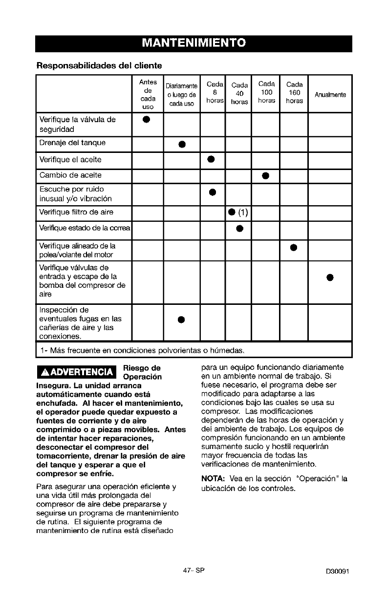
Responsabilidades del cliente
Antes Oiariamente Cada Cada Cada Cada
de o luego de 8 40 100 160
cada cade uso horas horas horas horas
uso
Verifique la valvula de •
seguridad
Drenaje del tanque
Verifique el aceite •
Anualmen_
Cambio de aceite
Escuche pot ruido •
inusual y/o vibracion
Verifique filtro de aire • (1
Vefifique estado de la correa •
Verifique aIineado de 18
polea_olante del motor
Verifique vaJvulas de
entrada y escape de la
bomba del compresor de
aire
InspecciSn de
eventuales fugas en las
caSer{as de aire y las
conexiones.
1- M_s frecuente en condiciones polvorientas o ht_medas,
Riesgo de
Operacibn
Insegura, La unidad arranca
automaticamente cuando esta
enchufada. AI hacer el mantenimiento,
el operador puede quedar expuesto a
fuentes de corriente y de aire
comprimido o a piezas movibles. Antes
de intentar hacer reparaciones,
desconectar el compresor del
tomacorriente, drenar la presibn de aire
del tanque y esperar a que el
compresor se enfrJe=
Para asegurar una operaci6n eficiente y
una vida Qtil mas prolongada del
compresor de aire debe prapararse y
seguirse un programa de mantenimiento
de rutina. El siguiente programa de
mantenimiento de rutina est& dise_ado
para un equipo funcionando diadamente
en un ambiente normal de trabajo. Si
fuese necesario, el programa debe ser
modfficado para adaptarse alas
condiciones bajo las cuales se usa su
compresor, Las modificaciones
depender&n de las horas de operacion y
del ambiente de trabajo. Los equipos de
compresi6n funcionando en un ambiente
sumamente sucio y hostil requerir&n
mayor frecuencia de todas las
verificaciones de mantenimiento.
NOTA: Vea en la seccion "Operaci6n" la
ubicacion de los controles.
47_ SP D30091
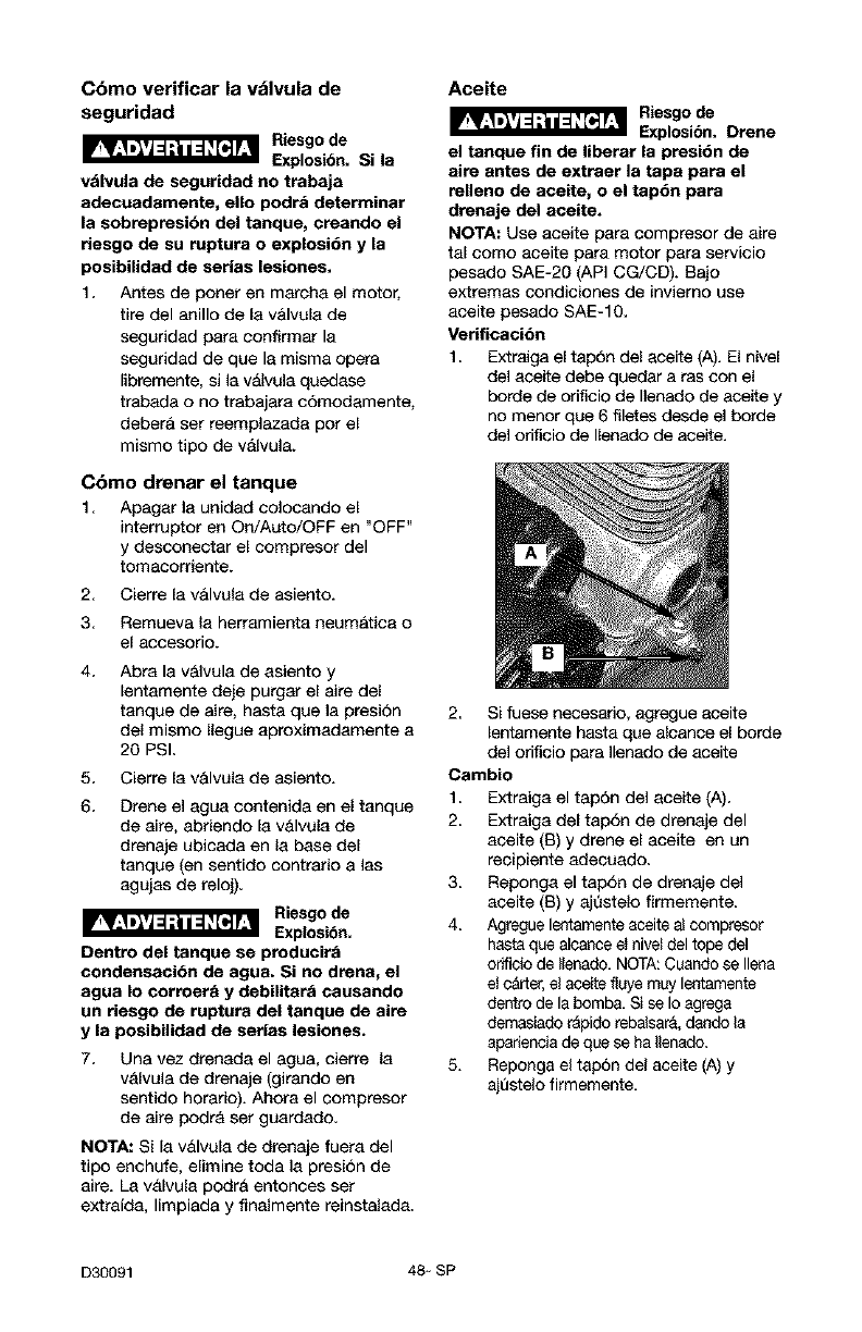
Cbmo verificar la vblvula de
seguridad
Riesgo de
Explesibn, Si la
valvula de seguridad no trabaja
adecuademente, ello podia detetminar
la sobreptesibn del tanque, eteando el
riesgo de su ruptura o explosibn y la
posibilided de setlas lesiones.
1. Antes de porter en mercha el motor,
tire del anillo de la v&lvula de
seguridad para confirmer la
seguridad de que la misma opera
libremente, si la v&lvuta quedase
trabada o no trabajera c6modamente,
deber& set reemplazada pot el
mismo tipo de vAlvula.
Cbmo drenar el tanque
1 Apagar la unidad colocando el
interruptor en On/Auto/OFF en "OFF"
y desconecter el compresor del
tomacorriente.
2.
3.
4.
5.
6.
Cierrela valvula de asiento.
Remueva la herramienta neumatica o
el accesorio.
Abra la valvula de asiento y
lentamente deje purger el aire del
tanque de aire, hasta que la presion
del mismo Ilegue aproximadamente a
20 PSL
Cierre la v&lvula de asiento.
Drene el agua contenida en el tanque
de aire, abriendo la v&lvula de
drenaje ubiceda en la base de[
tanque (en sentido contrerio a tas
agujas de reloj).
Riesgo de
Explosibn.
Dentro del tanque se producira
condeneacibn de ague. Si no dtene, el
agua Io corroer_ y debilitara causando
un riesgo de rupture del tanque de aire
y la posibilidad de serlas lesiones.
Una vez drenada el agua, cierre la
valvula de drenaje (girando en
sentido horerio). Ahora el eompresor
de aire podr& set guerdado.
NOTA: Si la v&lvula de drenaje fuera del
tipo enchufe, elimine toda la presi6n de
aire. La valvula podra entonces set
extrafda, limpiada y finalmente reinstalada.
Aceite
_Riesgo de
Explosibn. Drene
el tanque fin de liberar la ptesibn de
aim antes de extraer la tapa para el
relleno de aeeite, o el tap6n para
drenaje del aceite.
NOTA: Use aceite pare eompresor de aire
tal como aceite para motor para servicio
pesado SAE-20 (API CG/CD). Bejo
extremas condiciones de inviemo use
aceite pesado SAE-10.
Verificacibn
1. Extraiga el tap6n del aceite (A). El nivel
del aceite debe queder a ras con el
borde de orificio de Ilenedo de aceite y
no menor que 6 filetes desde el borde
del orificio de Ilenado de aceite.
2 Si fuese neceserio, agregue aceite
lentamente hasta que alcance el borde
del orificio para Ilenado de aceite
Cambio
1. Extraiga el tap6n del aceite (A)<
2< Extraiga del tap6n de drenaje del
aceite (B) y drene el aceite en un
recipiente adecuado.
3. Reponga el tap6n de drenaje del
aceite (B) y aj0stelo firmemente.
4. Agregue lentamente aceite ai compresor
hasta que alcance eI nivel del tope del
odficio de Ilenado, NOTA:Cuando se Ilena
el carter, el aceite flsye muy lentamente
dentro de la bomb& Si se Io egrega
demasiado r_pido rebalsarA,dando la
apariencia de que se ha Ilenado.
5. Repenga el tap6n del aceite (A) y
ajastelo firmemente,
D30091 48- SP
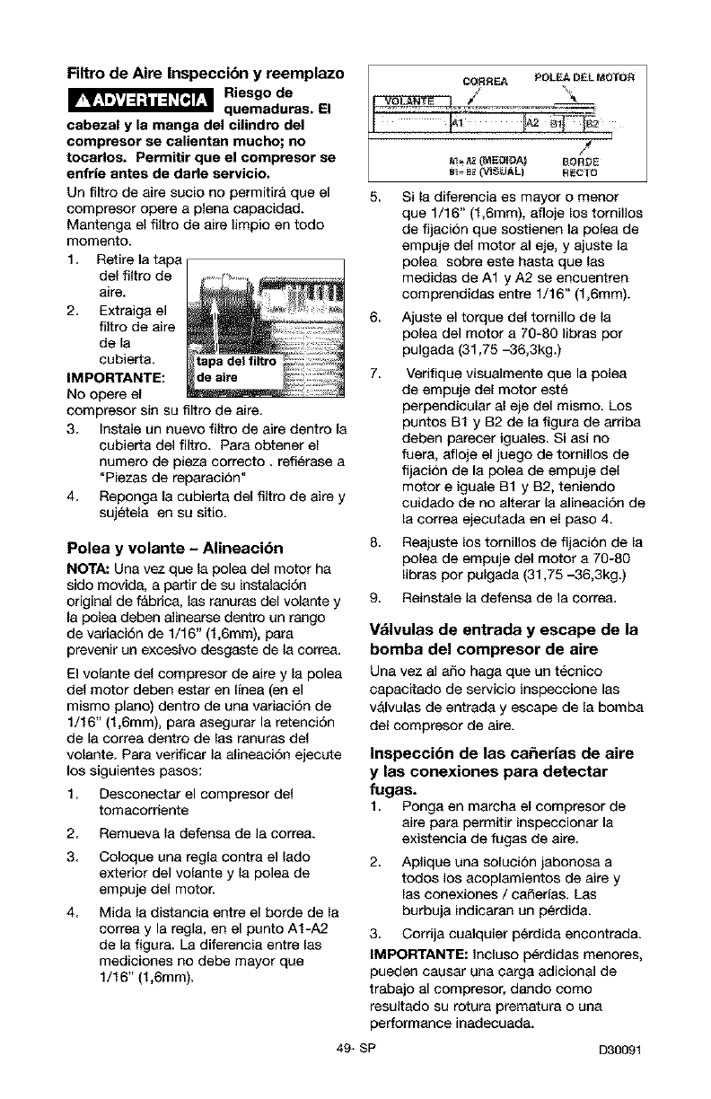
Filtro de Aire Inspeccibn y reemplazo
_Riesgo de
quemaduras. El
cabezal y la manga del cilindro del
compresor se calientan mucho; no
tocados. Permitir que el compresor se
enfrle antes de dade servicio,
Un filtro de aire sucio no permitira que el
compresor opera a plena capacidad.
Mantenga el filtro de aire limpio en todo
momento.
1. Retire la tapa
del filtro de
aire.
2. Extraiga el
filtro de aire
de la
eubierta.
IMPORTANTE:
No opera el
compresor sin su filtro de aire.
3. Instale un nuevo filtro de alre dentro la
cubierta dal filtro. Para obtener el
numero de pieza eorrecto, refi_rase a
"Piezas de reparacion"
4. Reponga la cubierta del filtro de alre y
sujetela en su sitio.
COR R_A _OL_ D£L _0_
/
B1- 82 (TJ_UAL) R_CTO
5.
8,
7.
Polea y volante -Alineaci6n 8
NOTA: Una vez qua la palea del motor ha
sido movida, a partir de su instalaalon
original de f&brica, las ranuras del volante y 9.
la polea deben alinearse dentro un tango
de variacidn de 1/16" (1,6mm), para
prevenir un excesivo desgaste de la correa.
El voJante deJ compresor de alre y la polea
del motor deben estar en linea (en el
mismo piano) dentro de una variaal6n de
1/16" (1,6mm), para asegurar la retenal6n
de la eorrea dentro de las ranuras del
volante. Para verificar la alineaal6n ejecute
los siguientes pasos:
1. Desconectar el compresor de{
tomacorriente
2. Remueva la defensa de la correa.
3. Coloque una regla contra el lado
exterior del volante y la polea de
empuje del motor.
Mida la distancia entre el borde de la
correa y la regla, en el punto A1-A2
de la figura. La diferenala entre las
medieiones no debe mayor que
1/16" (1,6mm).
4,
Si la diferencia es mayor o menor
que 1/16" (1,6ram), afloje los tornillos
de fljacion que sostienen la polea de
empuje del motor al eje, y ajuste la
polea sobre este hasta que las
medidas de A1 y A2 se eneuentren
eomprendidas entre 1/16" (1,6ram).
Ajuste el torque del tornillo de la
polea del motor a 70-80 libras pot
pulgada (31,75 -36,3kg.)
Verifique visualmente que la polea
de empuje del motor este
perpendicular al eje del mismo. Los
puntos B1 y B2 de la figura de arriba
deben parecer iguales. Si asi no
fuera, afloje el juego de tomillos de
fljacion de la polea de empuje del
motor e iguale B1 y B2, teniendo
cuidado de no alterar la alineaci6n de
la correa ejecutada en el paso 4.
Reajuste los tornillos de fijacion de la
polea de empuje dal motor a 70-80
libras por pulgada (31,75 -36,3kg.)
Reinstale la defensa de la correa.
Vdlvulas de entrada y escape de la
bomba del compresor de aire
Una vez al aSo haga que un tecnico
capacitado de servicio inspeccione las
valvulas de entrada y escape de la bomba
del compresor de alre.
Inspecci6n de las caSerias de aire
y las conexiones para detectar
fugas.
1. Ponga en marcha el compresor de
aire para permitir inspeealonar la
existencia de fugas de alre,
2. Aplique una solucion jabonosa a
todos los acoplamientos de alre y
las eonexiones /caSerfas. Las
burbuja indicaran un perdida.
3. Cordja cualquier p_rdida encontrada.
IMPORTANTE: Incluso p_rdidas menores,
pueden causar una carga adicional de
trabajo al compresor, dando como
resultado su rotura prematura o una
performance inadecuada.
49* SP D30091
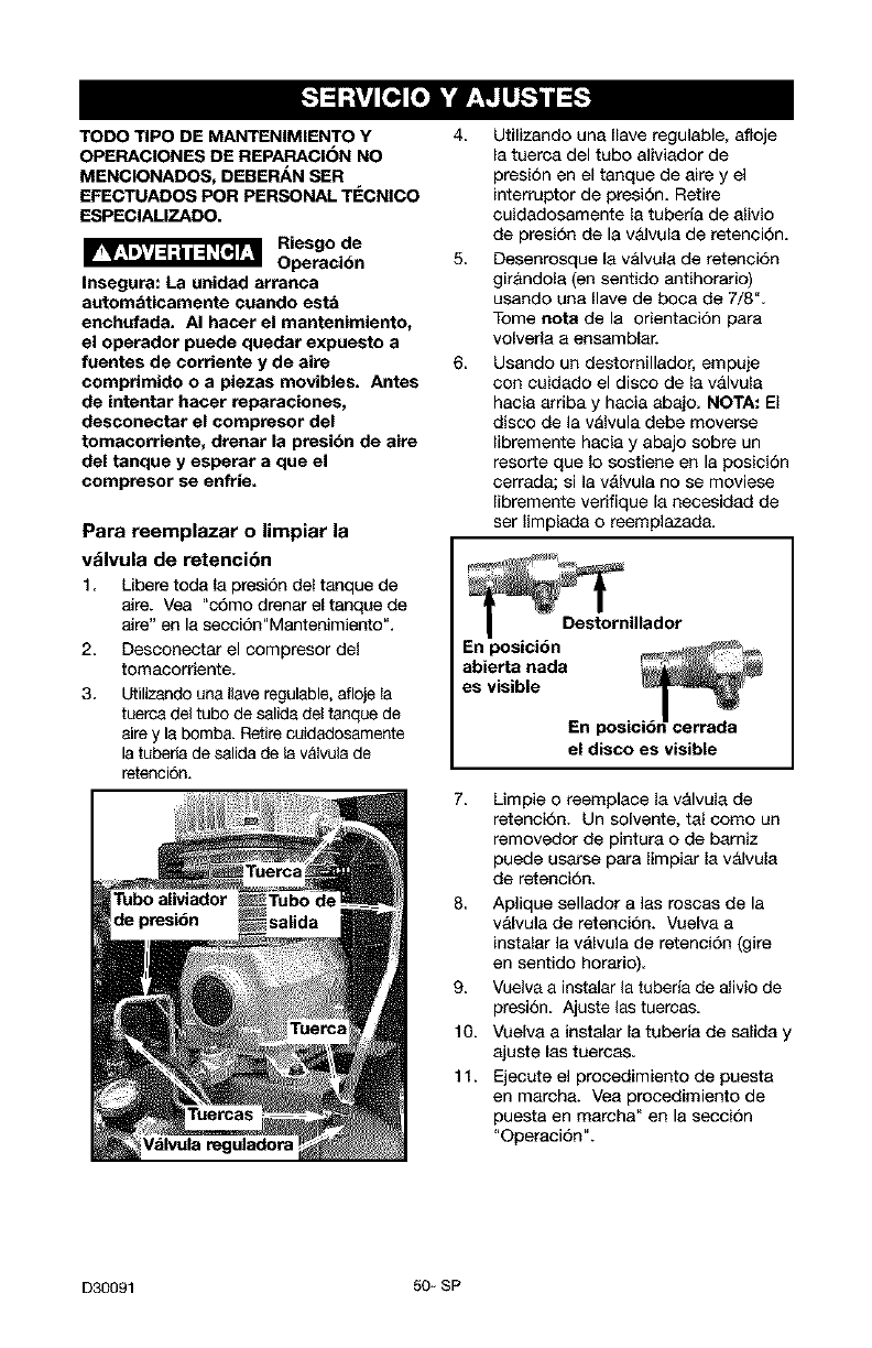
TODO TIPO DE MANTENIMIENTO Y
OPERACIONES DE REPARACION NO
MENCIONADOS, DEBEP_N SER
EFECTUADOS POR PERSONAL TI_CNICO
ESPECIALIZADO.
Riesgo de
Operacidn
Insegura: La unidad arranca
automaticamente cuando esta
enchufada. AI hacer el mantenimiento,
el operador puede quedar expuesto a
fuentes de corriente y de aire
comprimido o a piezas movibles. Antes
de intentar hacer reparaciones,
desconectar el compresor del
tomacorriente, drenar la presidn de aire
del tanque y esperar a que el
compresor se enfrie=
Para reemplazar o limpiar la
vblvula de retencibn
1. Libere toda la presion del tanque de
aire. Vea "c6mo drenar el tanque de
aire" en la seccion"Mantenimiento".
2. Desconectar el compresor del
tomacorriente.
3. Utilizando una Ilave regulable, aflcje Ia
tuerea del tubo de salida del tanque de
sire y la bomba. Retire cuidadcsamente
la tuberia de salida de la valvula de
retenci6n.
Calvula reguladora
4. Utilizando una Ilave regulable, afloje
la tuerca del tubo aliviador de
presion en el tanque de aire y el
interruptor de presi6n. Retire
cuidadosamente la tubefla de alivio
de presion de la vaJvula de retenci6n.
5. Deeenroeque la vMvula de retenci6n
girandola (en sentido antihorario)
usando una Ilave de boca de 7/8".
Tome nora de la orientacion para
volverla a ensamblar.
6. Usando un destomillador, empuje
con cuidado el disco de la valvula
hacia arriba y hacia abajo. NOTA: El
disco de la valvula debe moveree
libremente hacia y abajo sobre un
resorte que Io soetiene en la posicion
cerrada; si la valvula no se moviese
libremente verifique la necesidad de
ser limpiada o reemplazada.
el disco es visible
7. Limpie o reemplace la valvula de
retencion. Un solvente, tal come un
removedor de pintura o de bamiz
puede usarse para limpiar la valvula
de retenci6n.
8. Aplique sellador a las roecas de la
valvula de retencion. Vuelva a
instalar la valvula de retencion (gire
en sentido horatio).
9. Vuelva a instalar la tuberia de alivio de
presion. Ajuste las tuercas.
10. Vuelva a instalar la tuberia de salida y
ajuste las tuercas.
11. Ejecute el procedimiento de puesta
en marcha. Yea procedimiento de
pueeta en marcha" en la eeccion
"Operaci6n".
D30091 50 - SP
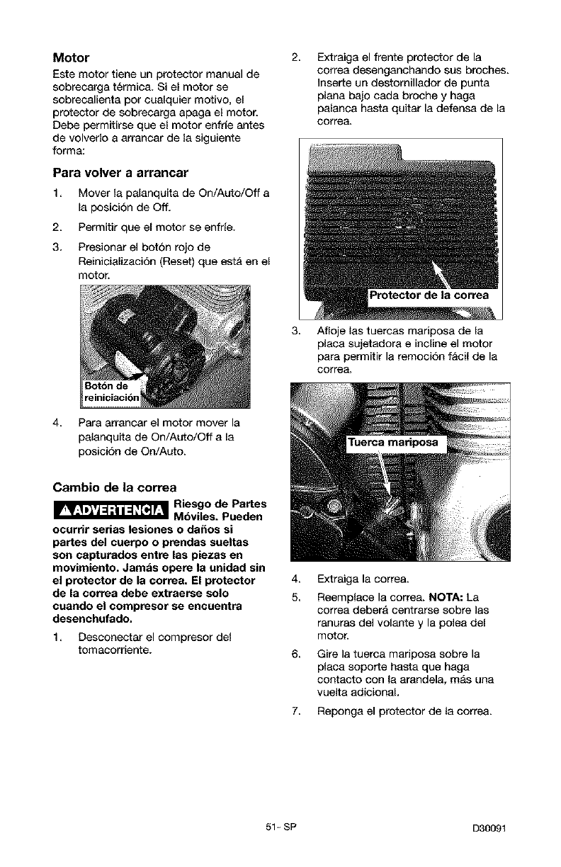
Motor
Este motor tiene un protector manual de
sobrecarga t_rmica. Si el motor se
sobrecalienta pot cualquier motivo, el
protector de sobrecarga apaga el motor.
Debe permitirse que el motor enfde antes
de volverlo a arrancar de la siguiente
forma:
Para volver a arrancar
1. Mover la palanquita de On/Auto/Off a
la posici6n de Off.
2. Permitir que el motor se enfrie.
3. Presionar el boton rojo de
Reinicializaci6n (Reset) que estA en el
motor.
2, Extraiga el frente protector de la
correa desenganchando sus broches.
Inserte un destomillador de punta
plana baio cada broche y haga
palanca hasta quitar la defensa de la
correa,
3, Afloje las tuercas maripose de la
placa suietadora e incline el motor
para permitir la remoei6n Iacil de la
eorrea,
4 Para arrancar el motor mover la
palanquita de On/Auto/Off a la
posici6n de On/Auto.
Cambio de la correa eS °e.%t es
ocurrir serias lesiones o da_os si
partes del cuerpo o prendas sueltas
son capturedos entre las piezes en
movimiento. Jambs opere le unidad sin
el protector de la correa. El protector
de la correa debe extraerse solo
cuando el compresor se encuentra
desenchufado,
1 Desconectar el compresor de{
tomacorriente.
4,
5.
6,
Extraiga la correa
Reemp{ace la correa. NOTA: La
correa debera centrarse sobre las
tenures del volante y la polea del
motor.
Gire ]a tuerce mariposa sobre la
placa soporte hasta que haga
contacto con la arandela, mas una
vuelta adicionaL
7 Reponga el protector de la correa.
51 _ SP D3009t

Antes de guarder su compresor de aire,
asegQrese de haeer Io siguiente:
Revise la secci6n "Mantenimiento"
de Ins p&ginas precedentes y ejecute
el mantenimiento programado de
aeuerdo a la necesidad.
2. Apagar la unidad colocando el
interruptor en On/Auto/OFF en "OFF"
y descenectar el compresor del
tomacorriente.
3 Cierre la vMvala de asiento
4 Extraiga la herramienta neumatica o
el accesorio.
5. Abra la valvula de asiento y
lentamente deje purgar el aire del
tanque de aire, hasta que la presion
del mismo Ilegue aproximadamente a
20 PSL
6. Drene el agua del tanque de aire
abriendo la valvula de drenaje
ubicada en el fondo del tanque,
giranda en sentido antihorario.
_Riesgo de
Explosibn. El agua
se condensa dentro del tanque de aite.
Si no se dtene, ella cotroerd debUitando
les paredes del tanque de aire,
originando un riesgo de ruptura de sus
paredes, y poeibles serias lesiones
personeles.
7. Una vez que el agua haya sido
drenada, cierre la valvula de drenaje.
NOTA; Si la valvula de drenaje estuviese
enchufada, libere toda la presion de aire.
La valvula podra ser extrafda, limpiada y
luego reinstalada.
8. Proteja la manguera del aire de
da_os (tales como ser pisoteada o
caminar pot eneima).
D30091 52_ SP
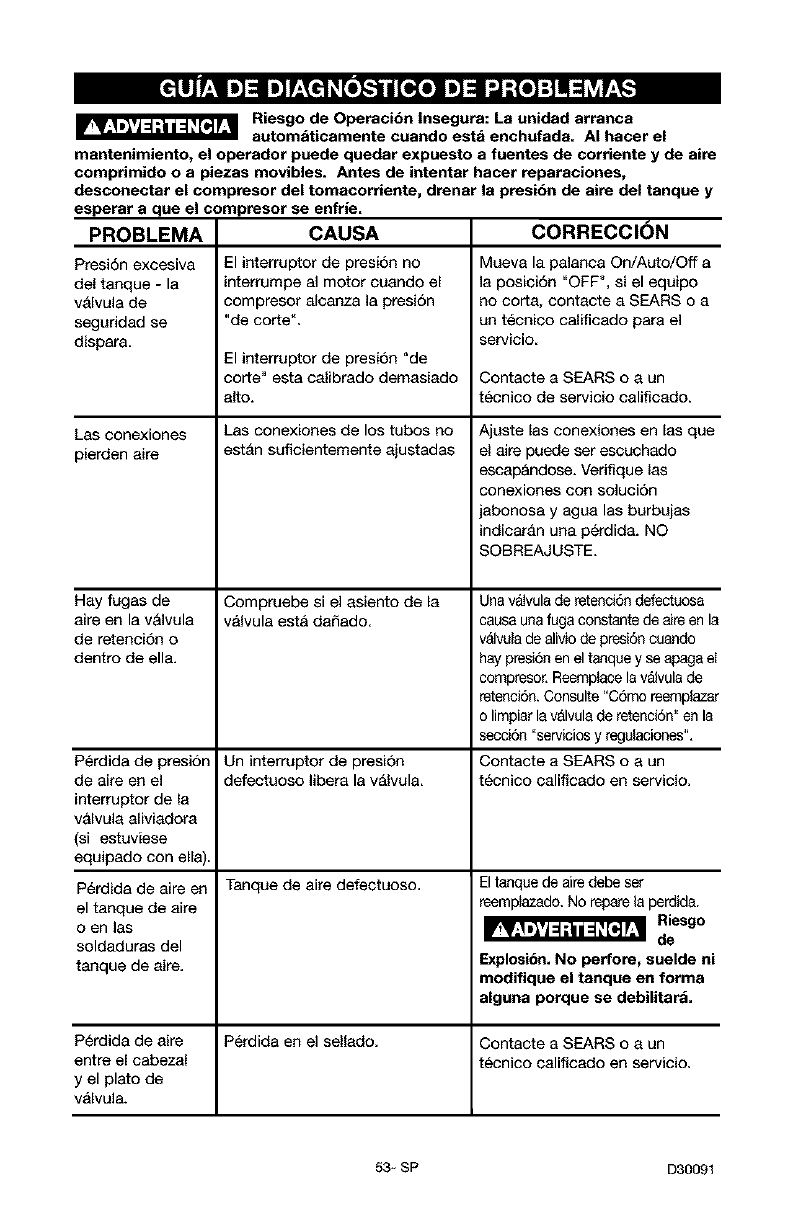
Riesgo de Operacibn Insegura: La unidad arranca
automaticamente cuando esta enchufada. AI hacer el
mantenimiento, el operador puede quedar expuesto a fuentes de corriente y de aire
compdmido o a piezas movibles. Antes de intentar hacer reparaciones,
desconectar el compresor del tomacorriente, drenar la presibn de aire del tanque y
esperar a que el compresor se enfrie.
CAUSA CORRECCION
PROBLEMA
Presi6n excesiva
del tanque - la
valvula de
segaridad se
dispara.
Las conexiones
pierden aire
Hay fugas de
aire en la valvula
de retencion o
dentro de ella.
Perdida de presion
de aire en el
interruptor de la
valvula aliviadora
(si estuviese
equipado con ella)
P_rdida de aire en
el tanque de aire
o en las
soldaduras del
tanque de aire.
El interruptor de presion no
interrumpe al motor cuando el
compresor alcanza la presi6n
"de corte _.
El interruptor de presion "de
corte" esta calibrado demasiado
alto.
Las conexiones de los tubos no
estAn suficientemente ajustadas
Compruebe si el asiento de la
vAIvula esta daSado
Un interruptor de presi6n
defectuoso libera la valvula,
Tanque de aire defectuoso.
Mueva la palanca On/Auto/Off a
la posici6n "OFF% si el equipo
no corta, contacte a SEARS o a
un t_cnieo calificado para el
;ervicio.
Contacte a SEARS o a un
tecnico de servicio calificado.
Ajuste las conexiones en las que
el aire puede ser escuchado
escap&ndose. Verifique las
conexiones con soluoi6n
jabonosa y agua las burbujas
indicar&n una perdida. NO
SOBREAJUSTE,
Una v_Jvulade retenci6n defectuosa
causa una fuga constante de aire en la
v_lvula de aliviode presi6n cuando
hay presi6n en el tanque y se apaga el
compresor. ReemplaceIs v_vula de
retenci6n. Consulte "C6mo reemplazar
o limpiar Is valvula de retenci6n" an la
secci6n "servicios y regulaciones".
Contacte a SEARS o a un
tecnico calificado en servicio.
Eltanque de aire debe set
reemplazado. No repare la perdid&
Riesgo
de
Explosibn. No perfore, suelde ni
modifique el tanque en forma
alguna porque se debilitara.
Perdida de aire Perdida en el sellado. Contacte a SEARS o a un
entre el cabezal tecnico calificado en servicio.
y el plato de
v_lvula.
53_ SP D30091
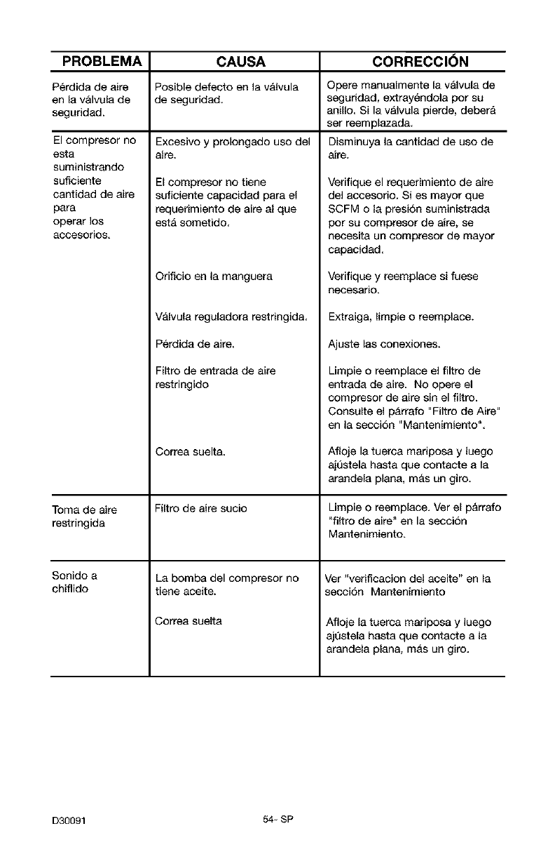
PROBLEMA CAUSA CORRECCI(_N
Perdida de aire Posible defecto en la v_lvula Opere manualmente la valvula de
en la v&lvula de de seguridad, seguridad, extray6ndola por su
seguridad, anillo. Si la valvula pierde, deberA
set reemplazada.
Excesivo y prolongado uso del Disminuya la cantidad de uso de
aire. aire.
El compresor no
esta
suministrando
suficiente
cantidad de aire
para
operar los
8ccesorios,
El compresor no tiene
suficiente capacidad para el
requerimiento de aire al que
esta sometido.
Orificio en la manguera
Valvula reguladora restringida.
Perdida de aire.
Filtro de entrada de aire
restringido
Correa suelta.
Veriflque el requerimiento de aire
del accesorio. Si es mayor que
SCFM o la presion suministrada
pot su compresor de aire, se
necesita un compresor de mayor
capacidad.
Verifique y reemplace si fuese
necesario.
Extraiga, limpie o reemplace+
Ajuste las conexiones+
Limpie o reemplace el filtro de
entrada de aire. No opere el
compresor de aire sin el filtro.
Consulte el parrafo "Filtro de Aire"
en la seccion "Mantenimiento".
Afloje la tuerca madposa y luego
ajestela hasta que contacte a la
arandela plana, mas un giro.
Toma de aire Filtro de aire sucio Limpie o reemplace. Ver el p&rrafo
restringida "filtro de aire" en la secci6n
Mantenimiento+
Sonido a La bomba del compresor no Ver "verificacion del aceite" en la
chiflido tiene aceite+ secci6n Mantenimiento
Correa suelta Afloje la tuerca mariposa y luego
ajQstela hasta que contacte a la
arandela plana, mAs un giro.
D30091 54- SP
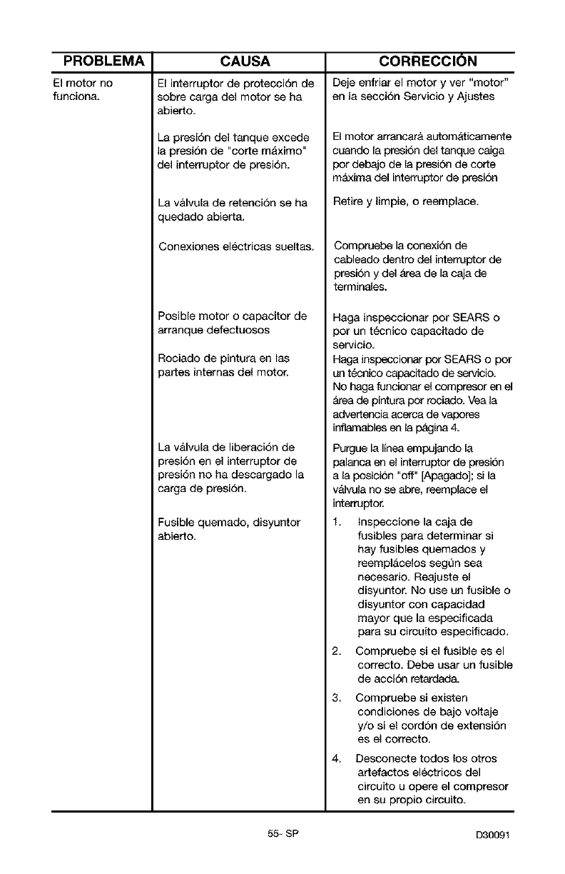
PROBLEMA
El motor no
funciona.
CAUSA
El interruptor de protecci6n de
sobre oarga del motor se ha
abierto.
La presi6n del tanque excede
la presi6n de "corte maximo"
del interruptor de presi6n.
La v&lvula de retenci6n se ha
quedado abiert&
Conexiones electricas sueltas.
Posible motor o capacitor de
arranqae defectuosos
Rociado de pintura en las
)artes intemas del motor.
_a v&lvula de liberaci6n de
)resi6n en el interruptor de
)resi6n no ha descargado la
;arga de presi6n.
Fusible quemado, disyuntor
abierto.
CORRECCION
Deje enfriar el motor y ver "motor"
en la secci6n Servicio y Ajustes
El motor arrancar& automaticamente
cuando la presion del tanque caiga
For debajo de la presion de corte
m_xima del interruptor de presion
Retire y limpie, o reemplace.
Compruebe la conexi6n de
cableado dentro del interraptor de
presion y del _ea de la caja de
terminales.
Haga inspeccionar FOr SEARS o
FOr un tecnico capacitado de
servicio.
Haga inspeccionar pot SEARS o pot
an t_cnico capacitedo de servicio.
No haga funcionar el compresor en el
&rea de pintura pot rociado. Vea la
advertencia acerca de vapores
inflamables ¢n la p&gina 4.
Purgue la linea empujando la
palanca en el interruptor de presi6n
a la Fosiebn "off" [Apagado]; si la
v_lvula no se abre, reemplace el
interruptor.
1. Inspeccione la caja de
fusibles para determinar si
hay fusibles quemados y
reemplacelos segQn sea
neoesario. Reajaste el
disyantor. No use an fusible o
disyuntor con capacidad
mayor que la especificada
para su circaito especificado.
2. Compruebe si el fusible es el
correcto+ Debe uear un fusible
de accion retardada.
3. Compruebe si existen
condiciones de bajo voltaje
y/o si el cordon de extensi6n
es el correcto.
4. Desconecte todos los otros
artefactos eleetdeos del
circuito u opere el compresor
en su propio circuito.
55 - SP D30091
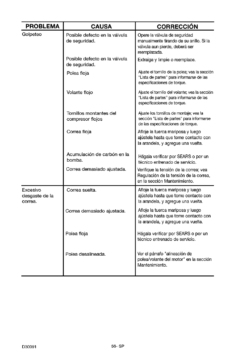
PROBLEMA
Golpeteo
CAUSA
Posible defecto en la valvula
Excesivo
desgaste de la
correa=
de seguridad.
Posible defecto en la valvula
de seguridad.
Polea floja
Volante flojo
Tomillos montantes del
compresor flojos
Correa floja
Acumulaci6n de carb6n en la
bomba.
Correa demasiado ajustada.
Correa sueRa.
Correa demasiado ajustada.
Polea floja
Polea desalineada.
CORRECCION
Opere la valvula de segundad
manualmente tirando de su aniilo. Si la
valvula aun pierde, debera ser
reemplazada.
Extraiga y limpie o reemplace.
Ajuste el tornillo de la polea; yea la secciOn
"Lista de panes" para informarse de las
especificaciones de torque.
Ajuste el tornillo de_volante; yea la secci6n
"Lista de panes" para informarse de tas
especificaciones de torque.
Ajuste los torniiios de montaje; yea la
secci6n "Usta de partes" para informarse
de tas especificaciones de torque.
Afloje la tuerca mariposa y luego
ajQstela hasta que tome contacto con
la arande{a, y agregue una vuelta.
H_gala verificar por SEARS o pot un
t_cnico entrenado de servicio.
Verifique la tensi6n de la correa; vea
RegulaciOn de la tensi6n de la correa,
en la secci6n Mantenimiento.
Afloje la tuerca mariposa y luego
ajQstela hasta que tome contacto con
la arande{a, y agregue una vuelta.
Afloje la tuerca mariposa y luego
ajQstela hasta que tome contacto con
la arande{a, y agregue una vuelta.
Hagala verificar por SEARS o por un
tecnico entrenado de servicio.
Vet el parrafo "alineaci6n de
polea/volante del motor" en la secci6n
Mantenimiento.
D30091 56+ SP

57_SP D30091

D30091 58-SP
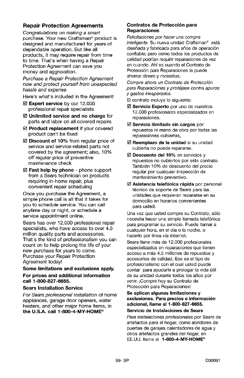
Repair Protection Agreements
Congratulations on making a smart
purchase. Your new Craftsman '_product is
designed and manufactured for years of
dependable operation. But like all
products, it may require repair from time
to time. That's when having a Repair
Protection Agreement can save you
money and aggravation.
Purchase a Repair Protection Agreement
now and protect yourself from unexpected
hassle and expense.
Here's what's included in the Agreement:
[_ Expert service by our 12,000
professional repair specialists
[_ Unlimited service and no charge for
parts and labor on all covered repairs
[_ Product replacement if your covered
product can't be fixed
1_ Discount of 10% from regular price of
service and service-related parts not
covered by the agreement; also, 10%
off regular price of preventive
maintenance check
[_ Fast help by phone - phone support
from a Sears technician on products
requiring in-home repair, plus
convenient repair scheduling
Once you purchase the Agreement, a
simple phone call is all that it takes for
you to schedule service. You can call
anytime day or night, or schedule a
service appointment online.
Sears has over 12,000 professional repair
specialists, who have access to over 4.5
million quality parts and acceesodee.
That's the kind of professionalism you can
count on to help prolong the life of your
new purchase for years to come.
Purchase your Repair Protection
Agreement today!
Some limitations and exclusions apply.
For prices and additional information
call 1-800-827-6655.
Sears Installation Service
For Sears professional installation of home
appliances, garage door openers, water
heaters, and other major home items, in
the U.S.A. call f-800-4*MY-HOME _
Contratos de Preteccibn para
Reparaciones
Felicitaciones per hater una compra
inteligente, Su nueva unidad Craftsman ® est&
diseffada y fabricada para afros de operaci6n
confiable; pero come todos los productos de
ca_idad podrian requirir reparaciones de vez
en cuando. Ahi es cuando e_ Contrato de
Protecc}6n para Reparac}ones le puede
ahorrar dinero y motestias.
Cornpre ahora un Contrato de Protecci6n
para Reparaciones y prot_jase contra apuros
y gastos inesperados,
Et contrato incluye _o siguiente:
Servicio Experto per uno de nuestros
12.000 profesionales especializados en
reparaciones.
Servicio ilimitado sin cargos per
repuestos ni mane de obra per todas las
reparaciones cubiertas,
Reemplazo de la unidad si su unidad
cubierta no puede repararse.
Descuento del 10% en servicios y
repuestos no eubiertos per este contrato.
Tambi6n 10% de descuento del precio
regular per cualquier inspecci6n de
mantenimiento preventive.
Asistencia telefbnica rbpida per personal
t6cnico de soporte de Sears para tas
unidades que requieran repararse en su
domocilio en horarios convenientes
para usted.
Una vez que usted compre su Contrato, s61o
necesita hacer una simple Ilamada telef6nica
para programar su servicio. Puede Ilamar a
cua_quier hera, en et dia o la noche, o
hacerlo per linea via intemet.
Sears tiene mas de 12.000 profesionales
especializados en reparaciones que tienen
acceso amas 4,5 millones de repuestos y
accesorios de calidad. Ese es et tipo de
profesionalismo con el cual usted puede
contar para ayudarte a prologar la vida etil
de su unidad durante todos los afros per
venir, iCompre hey su Contrato de
Protecci6n para Reparaciones]
Se aplican algunas limitaciones y
exclusiones. Para precios e irrformacibn
adicional, Ilame al 1-800-827-6655.
Servicio de Instalaciones de Sears
,Data instalaciones profesionales per Sears de
artefactos para el hogar, come abridores de
puertas de garajes calentadores de agua y
otros artefactos grandes del hogar, en
EE.UU. Ilame al t-S00-4-MY-HOME _
59* SP D30091
Your Home
For repair - in your home - of all major brand appliances,
lawn and garden equipment, or heating and cooling systems,
no matter who made it, no matter who sold it!
For the replacement parts, accessories and
owner's manuals that you need to do-it-yourself.
For Sears professional installation of home appliances
and items like garage door openers and water heaters.
1-800-4-MY-HOME ® Anytime, day or night
(1-800-469-4663) (U.S.A. and Canada)
w_Nw.sears.com www.sears.c_
OurHome
For repair of carry-in products like vacuums, lawn equipment,
and electronics, call or go on-line for the nearest
Sears Parts and Repair Center.
1-800-488-1222 Anytime,dayornight(U.S.A.onty)
www.sears.com
To purchase a protection agreement (U.S.A.)
or maintenance agreement (Canada) on a product serviced by Sears:
1-600-827-6655 (U.S.A,) 1-800-361-6665 (Canada)
Parapedirservicb de reparacbn
a domidlb, y para ordenarpiezas:
1-688-SU-HOGAR_
Au Canadapourserviceen francois:
1-600-LE-FOYERMc
(1-800-_
www.sears.ca
SE/AR$
© Seats, Rcebt_ckand Co.
® Registered Trademark /TMTrademark /sMService Mark of Sears, Roebuck and Co.
® Marc_ Registr_da /TMM_rca de F_br_ca /sMMarca de Servicio de Sears, Roebuck and Co.
vc Marque de commerce /MDM_rque d_pos_e de Se_rs, Roebuck _nd Co.
