Craftsman 919184192 User Manual AIR COMPRESSOR Manuals And Guides L0906289
CRAFTSMAN Air compressor Manual L0906289 CRAFTSMAN Air compressor Owner's Manual, CRAFTSMAN Air compressor installation guides
User Manual: Craftsman 919184192 919184192 CRAFTSMAN AIR COMPRESSOR - Manuals and Guides View the owners manual for your CRAFTSMAN AIR COMPRESSOR #919184192. Home:Tool Parts:Craftsman Parts:Craftsman AIR COMPRESSOR Manual
Open the PDF directly: View PDF ![]() .
.
Page Count: 56
Owner's Manual
Oil Lube
Single Stage
Vertical Stationary
AiR COMPRESSOR
=Safety Guidelines
=Assembly
= Operation
=Maintenance
=Troubleshooting
= Repair Parts
CAUTION: Read the Safety Guidelines
and All Instructions Carefully Before
Operating.
Sears, Roebuck and Co., Hoffman Estates, IL 60179 U.S.A.
Visit our Craftsman website: www.sears.com/craftsman
N001248 Rev.0 04/15/08
WARRANTY ................................................ 2
SPECiFiCATiON CHART ...................................... 2
SAFETY GUiDELiNES ...................................... 3-8
GLOSSARY ................................................ 9
DUTY CYCLE ............................................... 9
ACCESSORIES ............................................. 9
ASSEMBLY ............................................... 10
INSTALLATION ......................................... 10-12
OPERATION ............................................ 13-15
MAINTENANCE ......................................... 16-20
SERVICE AND ADJUSTMENTS ............................... 20
STORAGE ................................................ 21
TROUBLESHOOTING GUIDE .............................. 22-24
REPAIR PARTS ......................................... 25-29
ESPANOL .............................................. 30-52
REPAIR PROTECTION AGREEMENTS ......................... 55
HOW TO ORDER REPAIR PARTS ...................... back cover
ONE YEAR FULL WARRANTY
If this product fails clue to a defect in material or workmanship within one year
from the date of purchase, Sears will at its option repair or replace it free of
charge. Contact Sears at 1-800-4-MY-HOME ®to arrange for repair, or return it
to the place of purchase for replacement.
If this product is used for commercial or rental purposes, this warranty applies
for only ninety days from the date of purchase.
This warranty gives you specific legal rights and you may have other rights
which vary from state to state.
Sears, Roebuck and Co., Dept. 817WA, Hoffman Estates, IL 60179
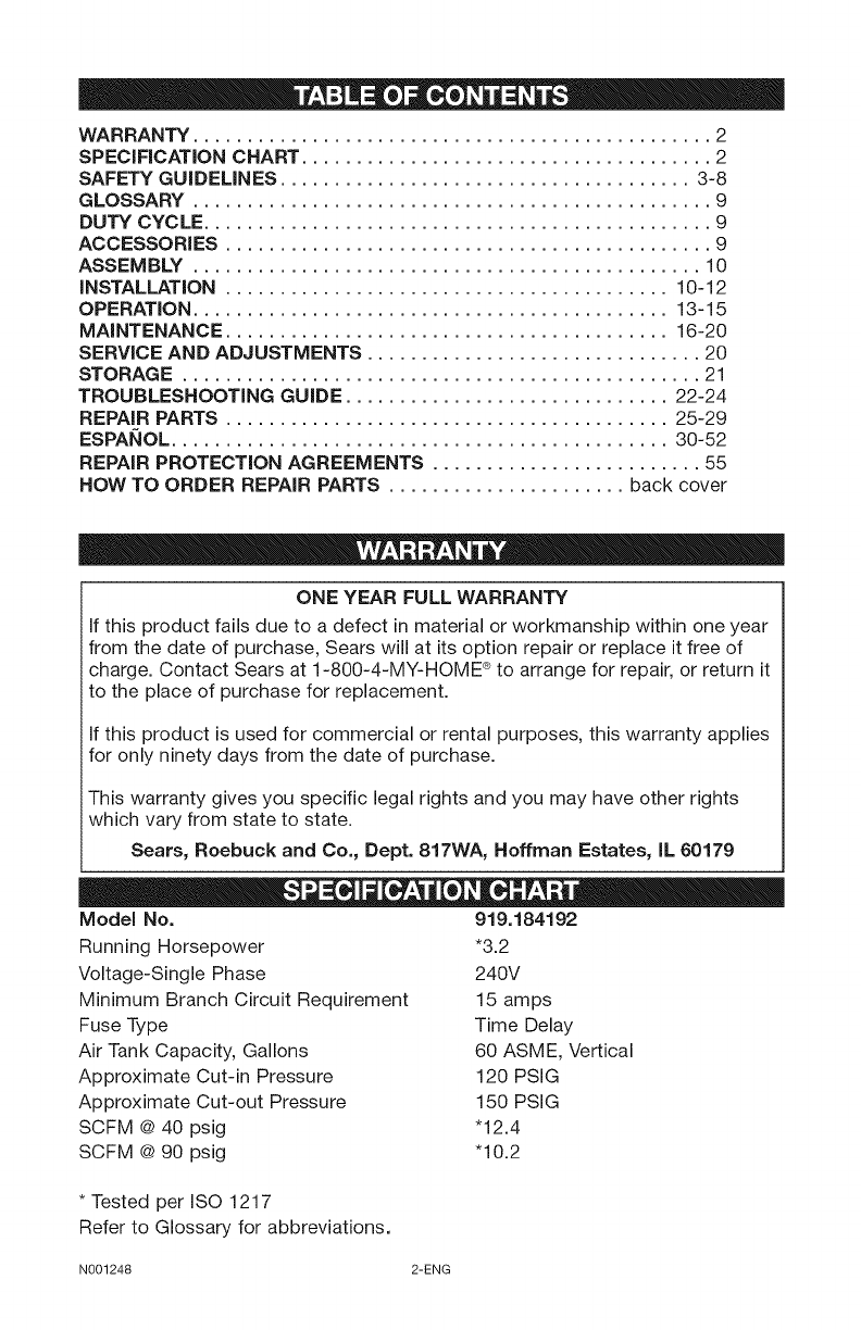
Model No.
Running Horsepower
Voltage-Single Phase
Minimum Branch Circuit Requirement
Fuse Type
Air Tank Capacity, Gallons
Approximate Cut-in Pressure
Approximate Cut-out Pressure
SCFM @ 40 psig
SCFM @ 90 psig
919.184192
*3.2
240V
15 amps
Time Delay
60 ASME, Vertical
120 PSIG
150 PSIG
"12.4
"10.2
* Tested per ISO 1217
Refer to Glossary for abbreviations.
N001248 2-ENG
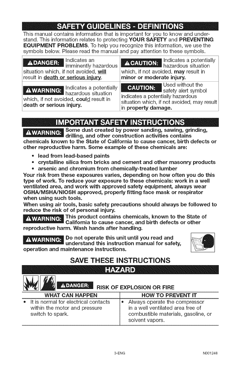
This manual contains information that is important for you to know and under-
stand. This information relates to protecting YOUR SAFETY and PREVENTING
EQUIPMENT PROBLEMS. To help you recognize this information, we use the
symbols below. Please read the manual and pay attention to these symbols.
I__ Indicates an
imminently hazardous
situation which, if not avoided, will
result in death or serious injury.
E__ ndicates a potentially
hazardous situation
which, if not avoided, could result in
death or serious injury.
I__ ndicates a potentially
hazardous situation
which, if not avoided, may result in
minor or moderate injury.
Used without the
safety alert symbol
indicates a potentially hazardous
situation which, if not avoided, may result
in property damage.
Some dust created by power sanding, sawing, grinding,
drilling, and other construction activities contains
chemicals known to the State of California to cause cancer, birth defects or
other reproductive harm. Some example of these chemicals are:
•lead from lead-based paints
• crystalline silica from bricks and cement and other masonry products
= arsenic and chromium from chemically-treated lumber
Your risk from these exposures varies, depending on how often you do this
type of work. To reduce your exposure to these chemicals: work in a well
ventilated area, and work with approved safety equipment, always wear
OSHA/MSHA/NIOSH approved, properly fitting face mask or respirator
when using such tools.
When using air tools, basic safety precautions should always be followed to
reduce the risk of of personal injury.
This product contains chemicals, known to the State of
California to cause cancer, and birth defects or other
reproductive harm. Wash hands after handling.
Do not operate this unit until you read and _A_lt
understand this instruction manual for safety,
operation and maintenance instructions.
SAVE THESE INSTRUCTIONS
RiSK OF EXPLOSION OR FiRE
WHAT CAN HAPPEN _ HOW TO PREVENT IT
= It is normal for electrical contacts = Always operate the compressor
within the motor and pressure in a well ventilated area free of
switch to spark, combustible materials, gasoline, or
solvent vapors.
3-ENG N001248
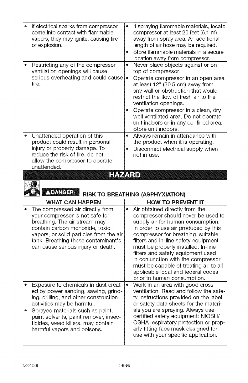
If electrical sparks from compressor
come into contact with flammable
vapors, they may ignite, causing fire
or explosion.
Restricting any of the compressor
ventilation openings will cause
serious overheating and could cause
fire.
• Unattended operation of this
product could result in personal
injury or property damage. To
reduce the risk of fire, do not
allow the compressor to operate
unattended.
__ RISK TO BREATHING (ASPHYXIATION)
If spraying flammable materials, locate
compressor at least 20 feet (6.1 m)
away from spray area. An additional
length of air hose may be required.
Store flammable materials in a secure
location away from compressor.
Never place objects against or on
top of compressor.
Operate compressor in an open area
at least 12" (30.5 cm) away from
any wall or obstruction that would
restrict the flow of fresh air to the
ventilation openings.
Operate compressor in a clean, dry
well ventilated area. Do not operate
unit indoors or in any confined area.
Store unit indoors.
Always remain in attendance with
the product when it is operating.
Disconnect electrical supply when
not in use.
WHAT CAN HAPPEN
The compressed air directly from
your compressor is not safe for
breathing. The air stream may
contain carbon monoxide, toxic
vapors, or solid particles from the air
tank. Breathing these contaminant's
can cause serious injury or death.
Exposure to chemicals in dust creat-
ed by power sanding, sawing, grind-
ing, drilling, and other construction
activities may be harmful.
Sprayed materials such as paint,
paint solvents, paint remover, insec-
ticides, weed killers, may contain
harmful vapors and poisons.
HOW TO PREVENT IT
Air obtained directly from the
compressor should never be used to
supply air for human consumption.
In order to use air produced by this
compressor for breathing, suitable
filters and in-line safety equipment
must be properly installed. In-line
filters and safety equipment used
in conjunction with the compressor
must be capable of treating air to all
applicable local and federal codes
prior to human consumption.
Work in an area with good cross
ventilation. Read and follow the safe-
ty instructions provided on the label
or safety data sheets for the materi-
als you are spraying. Always use
certified safety equipment: NIOSH/
OSHA respiratory protection or prop-
erly fitting face mask designed for
use with your specific application.
N001248 4-ENG
_I__ RiSK OF SERIOUS iNJURY OR PROPERTY DAMAGE
WHEN TRANSPORTING COMPRESSOR
WHAT CAN HAPPEN HOW TO PREVENT iT
=Oil can leak or spill and could = Always place compressor on a
result in fire or breathing hazard; protective mat when transporting
serious injury or death can result, oil to protect against damage to vehicle
leaks will damage carpet, paint or from leaks. Remove compressor
other surfaces in vehicles or trailers, from vehicle immediately upon
arrival destination.
R sKoFBURSTING
Air Tank: The air tank on your Air Compressor is designed and may be UM
coded (for units with air tanks greater than 6 inch diameter) according to ASME
Section VIII, Div. 1 rules. All pressure vessels should be inspected once every
two years. To find your state pressure vessels inspector, look under the Division
of Labor and Industries in the government section of a phone book.
The following conditions could lead to a weakening of the air tank, and result in
a violent air tank explosion:
WHAT CAN HAPPEN HOW TO PREVENT IT
• Failure to properly drain condensed • Drain air tank daily or after each use.
water from air tank, causing rust and If air tank develops a leak, replace it
thinning of the steel air tank. immediately with a new air tank or
replace the entire compressor.
Modifications or attempted repairs to • Never drill into, weld, or make any
the air tank. modifications to the air tank or its
attachments. Never attempt to
repair a damaged or leaking air tank.
Replace with a new air tank.
Unauthorized modifications to the • The air tank is designed to withstand
safety valve or any other components specific operating pressures.
which control air tank pressure. Never make adjustments or parts
substitutions to alter the factory set
operating pressures.
Excessive vibration can weaken the • The compressor must be properly
air tank of a stationary compressor mounted, see "Anchoring" under
and cause an explosion. Installation.
Attachments & accessories:
Exceeding the pressure rating of
air tools, spray guns, air operated
accessories, tires, and other
inflatables can cause them to
explode or fly apart, and could result
in serious injury.
Follow the equipment manufacturers
recommendation and never exceed
the maximum allowable pressure
rating of attachments. Never use
compressor to inflate small low
pressure objects such as children's
toys, footballs, basketballs, etc.
5-ENG N001248
__ RISK OF ELECTRICAL SHOCK
WHAT CAN HAPPEN
Your air compressor is powered by
electricity. Like any other electrically
powered device, If it is not used
properly it may cause electric shock.
•Repairs attempted by unqualified
personnel can result in serious injury
or death by electrocution.
• Electrical Grounding: Failure to
provide adequate grounding to this
product could result in serious injury
or death from electrocution. Refer to
"Grounding Instructions" paragraph
in the Installation section.
HOW TO PREVENT iT
Never operate the compressor
outdoors when it is raining or in wet
conditions.
Never operate compressor with
protective covers removed or
damaged.
Any electrical wiring or repairs
required on this product should be
performed by authorized service
center personnel in accordance with
national and local electrical codes.
Make certain that the electrical circuit
to which the compressor is connected
provides proper electrical grounding,
correct voltage and adequate fuse
protection.
__ RiSK FROM FLYING OBJECTS
HOW TO PREVENT iT
•Always wear certified safety
equipment: ANSI Z87.1 eye
protection (CAN/CSA Z94.3)
with side shields when using the
compressor.
•Never point any nozzle or sprayer
toward any part of the body or at
other people or animals.
•Always turn the compressor off
and bleed pressure from the air
hose and air tank before attempting
maintenance, attaching tools or
accessories.
WHAT CAN HAPPEN
The compressed air stream can
cause soft tissue damage to
exposed skin and can propel dirt,
chips, loose particles, and small
objects at high speed, resulting in
property damage or personal injury.
N001248 6-ENG
__ RISK OF HOT SURFACES
WHAT CAN HAPPEN
Touching exposed metal such as
the compressor head, engine head,
engine exhaust or outlet tubes, can
result in serious burns.
E==I °,sKF°oM
WHAT CAN HAPPEN
• Moving parts such as the pulley,
flywheel, and belt can cause serious
injury if they come into contact with
you or your clothing.
Attempting to operate compressor
with damaged or missing parts or
attempting to repair compressor
with protective shrouds removed
can expose you to moving parts and
can result in serious injury.
HOW TO PREVENT IT
Never touch any exposed metal
parts on compressor during or
immediately after operation.
Compressor will remain hot for
several minutes after operation.
• Do not reach around protective
shrouds or attempt maintenance
until unit has been allowed to cool.
o
o
MOVING PARTS
HOW TO PREVENT IT
Never operate the compressor
with guards or covers which are
damaged or removed.
Keep your hair, clothing, and gloves
away from moving parts. Loose
clothes, jewelry, or long hair can be
caught in moving parts.
Air vents may cover moving parts
and should be avoided as well.
Any repairs required on this product
should be performed by authorized
service center personnel.
7-ENG N001248
[__ RiSK OF UNSAFE OPERATION
WHAT CAN HAPPEN HOW TO PREVENT iT
= Unsafe operation of your air = Review and understand all
compressor could lead to serious inju- instructions and warnings in this
ry or death to you or others, manual.
• Become familiar with the operation
and controls of the air compressor.
Keep operating area clear of all
persons, pets, and obstacles.
Keep children away from the air
compressor at all times.
Do not operate the product when
fatigued or under the influence of
alcohol or drugs. Stay alert at all
times.
Never defeat the safety features of
this product.
Equip area of operation with a fire
extinguisher.
Do not operate machine with missing,
broken, or unauthorized parts.
[__ RiSK OF iNJURY FROM LiFTiNG
WHAT CAN HAPPEN / HOW TO PREVENT IT
L
= Serious injury can result from = The compressor is too heavy to
attempting to lift too heavy an I be lifted by one person. Obtain
_"" "' RiSK FROM NOISE
WHAT CAN HAPPEN ,, HOW TO PREVENT IT
= Undersome conditions and duration Always wear certified safety equipment:
of use, noisefrom this product may ANSI $12.6 (S3.19)hearing protection.
contribute to hearing loss.
SAVE THESE INSTRUCTIONS
N001248 8-ENG
Become familiar with these terms
before operating the unit.
CFM: Cubic feet per minute.
SCFM: Standard cubic feet per min-
ute; a unit of measure of air delivery.
PSIG: Pounds per square inch gauge;
a unit of measure of pressure.
Code Certification: Products that
bear one or more of the following
marks: UL, CUL, ETL, CETL, have
been evaluated by OSHA certified
independent safety laboratories and
meet the applicable Underwriters
Laboratories Standards for Safety.
Cut-In Pressure: While the motor is
off, air tank pressure drops as you
continue to use your accessory. When
the tank pressure drops to a certain
low level the motor will restart auto-
the motor automatically restarts is
called "cut-in" pressure.
Cut-Out Pressure: When an air
compressor is turned on and begins
to run, air pressure in the air tank
begins to build. It builds to a certain
high pressure before the motor auto-
matically shuts off - protecting your
air tank from pressure higher than its
capacity. The high pressure at which
the motor shuts off is called "cut-out"
pressure.
Branch Circuit: Circuit carrying elec-
tricity from electrical panel to outlet.
To Lock Out Power: Place a lock on
the line power switch so no one else
can turn on the power.
matically. The low pressure at which
This air compressor pump is capable average duty cycle be maintained; that
of running continuously. However, to is, the air compressor pump should
prolong the life of your air compressor, not run more than 30-45 minutes in
it is recommended that a 50%-75% any given hour.
This unit is capable of powering the following Accessories. The accessories are
available through the current Power and Hand Tool Catalog or full-line Sears
stores.
Accessories
•In Line Filter
•Tire Air Chuck
•Quick Connector Sets (various
sizes)
•Air Pressure Regulators
•Oil Fog Lubricators
•Air Hose: 1/4", 3/8" or 1/2" I.D. in
various lengths
Refer to the selection chart located on
the unit to select the tools this unit is
capable of powering.
_The use of any
-- other accessory
not recommended for use with
this tool could be hazardous. Use
only accessories rated equal to
or higher than the rating of the air
compressor.
9-ENG N001248
Tools Required for Assembly
1 - 9/16" socket or open end wrench
1 - Electric drill
Unpacking
1. Remove all packaging.
lt may be necessary
to brace or support
one side of the outfit when removing
the pallet because the air compressor
will have a tendency to tip.
2. Remove and discard the (4)
screws and washers holding the
compressor to the pallet.
3. With the help of another person
carefully remove air compressor
from pallet and place on a level
surface.
This compressor was
shipped with oil in
the pump crankcase. Check oil before
operating air compressor, see Check
Oil under Maintenance.
HOW TO SET UP YOUR UNiT
Location of the Air Compressor
• Locate the air compressor in a
clean, dry, and well ventilated
area.
Located the air compressor at
least 12" (30.5 cm) away from
the wall or other obstructions
that will interfere with the flow
of air.
Locate the air compressor as
close to the main power supply
as possible to avoid using long
lengths of electrical wiring.
NOTE: Long lengths of electri-
cal wiring could cause power
loss to the motor.
The air filter must be kept clear
of obstructions which could
reduce air flow to the air com-
pressor.
Anchoring of the Air Compressor
_Risk of Bursting.
__ Excessive
Vibration can weaken the air tank
and cause an explosion. The
compressor must be properly
mounted.
The air compressor MUST be bolted to
a solid, level surface.
Hardware needed:
4 - Concrete anchors
(not supplied)
4 - 3/8" Lag screw to fit concrete
anchors
(not supplied)
4 - 5/8" Washer (supplied)
shims (if needed)
1. Place the air compressor on a
solid, level surface.
2. Mark the surface using the holes
in the air compressor feet as a
template.
3. Drill holes in the surface for the
concrete anchors. Install concrete
anchors.
4. Line-up holes in surface with holes
in air compressor feet.
5. Place the (4) washers (supplied)
between the floor and air com-
pressor feet. If needed, solid
shims may be placed between the
washers and floor to evenly dis-
tribute weight on all four feet. See
next figure.
N001248 10-ENG
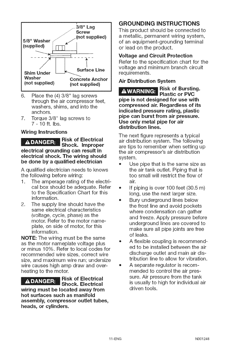
.......3/8" Lag
..................Screw
5/8" Washer ,................../(not supplied)
(supplied) i_" I
Sh,m___rface-- L,ne
Washer Concrete Anchor
(not supplied) (not supplied)
6. Place the (4) 3/8" lag screws
through the air compressor feet,
washers, shims, and into the
anchors.
7. Torque 3/8" lag screws to
7-10 ft. Ibs.
Wiring instructions
I_1__ Risk of Electrical
Shock. improper
electrical grounding can result in
electrical shock. The wiring should
be done by a qualified electrician
A qualified electrician needs to knows
the following before wiring:
1. The amperage rating of the electri-
cal box should be adequate. Refer
to the Specification Chart for this
information.
2. The supply line should have the
same electrical characteristics
(voltage, cycle, phase) as the
motor. Refer to the motor name-
plate, on side of motor, for this
information.
NOTE: The wiring must be the same
as the motor nameplate voltage plus
or minus 10%. Refer to local codes for
recommended wire sizes, correct wire
size, and maximum wire run; undersize
wire causes high amp draw and over-
heating to the motor.
I__ Risk of Electrical
Shock. Electrical
wiring must be located away from
hot surfaces such as manifold
assembly, compressor outlet tubes,
heads, or cylinders.
GROUNDING iNSTRUCTiONS
This product should be connected to
a metallic, permanent wiring system,
of an equipment-grounding terminal
or lead on the product.
Voltage and Circuit Protection
Refer to the specification chart for the
voltage and minimum branch circuit
requirements.
Air Distribution System
E__ isk of Bursting.
Plastic or PVC
pipe is not designed for use with
compressed air. Regardless of its
indicated pressure rating, plastic
pipe can burst from air pressure.
Use only metal pipe for air
distribution lines.
The next figure represents a typical
air distribution system. The following
are tips to remember when setting up
the air compressor's air distribution
system.
+ Use pipe that is the same size as
the air tank outlet. Piping that is
too small will restrict the flow of
air.
+ If piping is over 100 feet (30.5 m)
long, use the next larger size.
+ Bury underground lines below
the frost line and avoid pockets
where condensation can gather
and freeze. Apply pressure before
underground lines are covered to
make sure all pipe joints are free
of leaks.
+ A flexible coupling is recommend-
ed to be installed between the air
discharge outlet and main air dis-
tribution line to allow for vibration.
+ A separate regulator is recom-
mended to control the air pres-
sure. Air pressure from the tank
is usually to high for individual air
driven tools.
11-ENG N001248
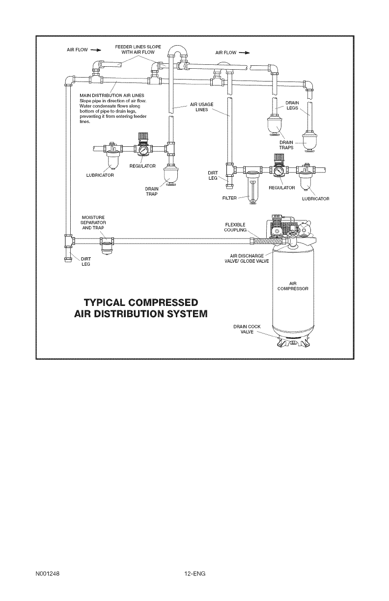
FEEDER LINES SLOPE
AIR FLOW _ WITH AIR FLOW AIR FLOW
DRAIN
LEGS
DRAIN .......
LUBRICATOR
MOISTURE £1
SEPARATOR FLEXIBLE
t_AND TRAP t-ilICOUPLING __¢
AIR DISCHARGE - _=_
\u,., VALVE_GLOBEVALVE
LEG
TYPICAL COMPRESSED
AiR DiSTRiBUTiON SYSTEM
DRAIN COCK
VALVE
AIR
COMPRESSOR
N001248 12-ENG
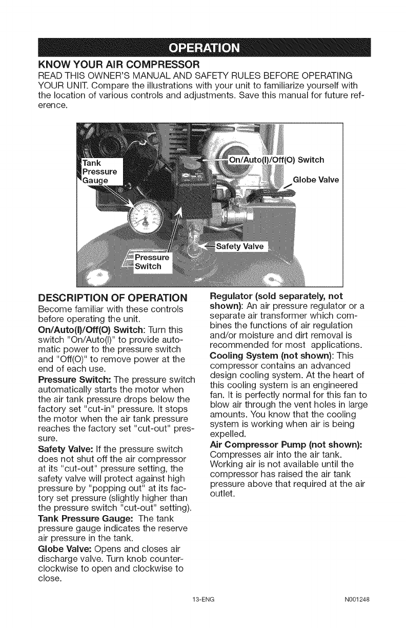
KNOW YOUR AiR COMPRESSOR
READ THIS OWNER'S MANUAL AND SAFETY RULES BEFORE OPERATING
YOUR UNIT. Compare the illustrations with your unit to familiarize yourself with
the location of various controls and adjustments. Save this manual for future ref-
erence.
Globe Valve
DESCRiPTiON OF OPERATION
Become familiar with these controls
before operating the unit.
On/Auto(I)/Off(O) Switch: Turn this
switch "On/Auto(I)" to provide auto-
matic power to the pressure switch
and "Off(O)" to remove power at the
end of each use.
Pressure Switch: The pressure switch
automatically starts the motor when
the air tank pressure drops below the
factory set "cut-in" pressure. It stops
the motor when the air tank pressure
reaches the factory set "cut-out" pres-
sure.
Safety Valve: If the pressure switch
does not shut off the air compressor
at its "cut-out" pressure setting, the
safety valve will protect against high
pressure by "popping out" at its fac-
tory set pressure (slightly higher than
the pressure switch "cut-out" setting).
Tank Pressure Gauge: The tank
pressure gauge indicates the reserve
air pressure in the tank.
Globe Valve: Opens and closes air
discharge valve. Turn knob counter-
clockwise to open and clockwise to
close.
Regulator (sold separately, not
shown): An air pressure regulator or a
separate air transformer which com-
bines the functions of air regulation
and/or moisture and dirt removal is
recommended for most applications.
Cooling System (not shown): This
compressor contains an advanced
design cooling system. At the heart of
this cooling system is an engineered
fan. It is perfectly normal for this fan to
blow air through the vent holes in large
amounts. You know that the cooling
system is working when air is being
expelled.
Air Compressor Pump (not shown):
Compresses air into the air tank.
Working air is not available until the
compressor has raised the air tank
pressure above that required at the air
outlet.
13-ENG N001248
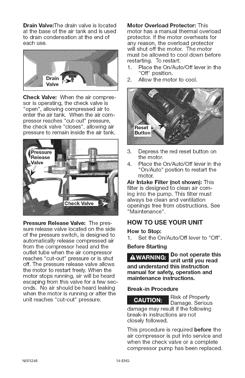
Drain Valve:The drain valve is located
at the base of the air tank and is used
to drain condensation at the end of
each use.
Motor Overload Protector: This
motor has a manual thermal overload
protector. If the motor overheats for
any reason, the overload protector
will shut off the motor. The motor
must be allowed to cool down before
restarting. To restart:
1. Place the On/Auto/Off lever in the
"Off" position.
2. Allow the motor to cool.
Check Valve: When the air compres-
sor is operating, the check valve is
"open", allowing compressed air to
enter the air tank. When the air com-
pressor reaches "cut-out" pressure,
the check valve "closes", allowing air
pressure to remain inside the air tank.
Pressure Release Valve: The pres-
sure release valve located on the side
of the pressure switch, is designed to
automatically release compressed air
from the compressor head and the
outlet tube when the air compressor
reaches "cut-out" pressure or is shut
off. The pressure release valve allows
the motor to restart freely. When the
motor stops running, air will be heard
escaping from this valve for a few sec-
onds. No air should be heard leaking
when the motor is running or after the
unit reaches "cut-out" pressure.
3. Depress the red reset button on
the motor.
4. Place the On/Auto/Off lever in the
"On/Auto" postion to restart the
motor.
Air intake Filter (not shown): This
filter is designed to clean air com-
ing into the pump. This filter must
always be clean and ventilation
openings free from obstructions. See
"Maintenance".
HOW TO USE YOUR UNiT
How to Stop:
1. Set the On/Auto/Off lever to "Off".
Before Starting
Do not operate this
unit until you read
and understand this instruction
manual for safety, operation and
maintenance instructions.
Break-in Procedure
Risk of Property
Damage. Serious
damage may result if the following
break-in instructions are not
closely followed.
This procedure is required before the
air compressor is put into service and
when the check valve or a complete
compressor pump has been replaced.
N001248 14-ENG
1. Make sure the On/Auto/Off lever is
in the "Off" position.
2. Check oil level in pump. See "Oil"
paragraph in the Maintenance
section for instructions.
3. Recheck all wiring. Make sure
wires are secure at all terminals
connections. Make sure all con-
tacts move freely and are not
obstructed.
4. Open the globe valve fully to per-
mit air to escape and prevent air
pressure build up in the air tank
during the break-in period.
5. Move the On/Auto/Off lever to
"On/Auto" position. The compres-
sor will start.
6. Run the compressor for 20 min-
utes. Make sure the globe valve
is open and there is minimal air
pressure build-up in tank.
7. Check all air line fittings and con-
nections/piping for air leaks by
applying a soap solution. Correct
if necessary. NOTE: Minor leaks
can cause the air compressor to
overwork, resulting in premature
breakdown or inadequate perfor-
mance.
8. Check for excessive vibration.
Readjust or shim air compressor
feet, if necessary.
9. After 20 minutes, close the globe
valve. The air receiver will fill to
"cut-out" pressure and the motor
will stop.
Before Each Start=Up:
1. Place On/Auto/Off lever to "Off".
2. Close the globe valve.
3. Attach hose and accessories.
_Risk of unsafe
-- operation. Firmly
grasp air hose in hand when
installing or disconnecting to
prevent hose whip.
Risk of unsafe
operation. Do not
use damaged or worn accessories.
NOTE: A regulator MUST be installed
when using accessories rated at less
than 175 Psi.
NOTE: The hose or accessory will
require a quick connect plug if the air
outlet is equipped with a quick con-
nect socket.
Risk of Bursting.
Too much air
pressure causes a hazardous risk of
bursting. Check the manufacturer's
maximum pressure rating for air
tools and accessories. The regulator
outlet pressure must never exceed
the maximum pressure rating.
_Risk of unsafe
-- operation.
Compressed air from the unit may
contain water condensation and
oil mist. Do not spray unfiltered air
at an item that could be damaged
by moisture. Some air tools and
accessories may require filtered
air. Read the instructions for the air
tools and accessories.
How to Start:
1. Turn the On/Auto/Off lever to "On/
Auto" and allow tank pressure to
build. Motor will stop when tank
pressure reaches "cut-out" pres-
sure.
2. When the tank pressure reaches
"cut-out" pressure open the globe
valve.
IMPORTANT: When using regula-
tor and other accessories refer to the
manufacturers instructions.
_lf any unusual
__ noise or vibration
is noticed, stop the compressor
immediately and have it checked by
a trained service technician.
The compressor is ready for use.
15-ENG N001248
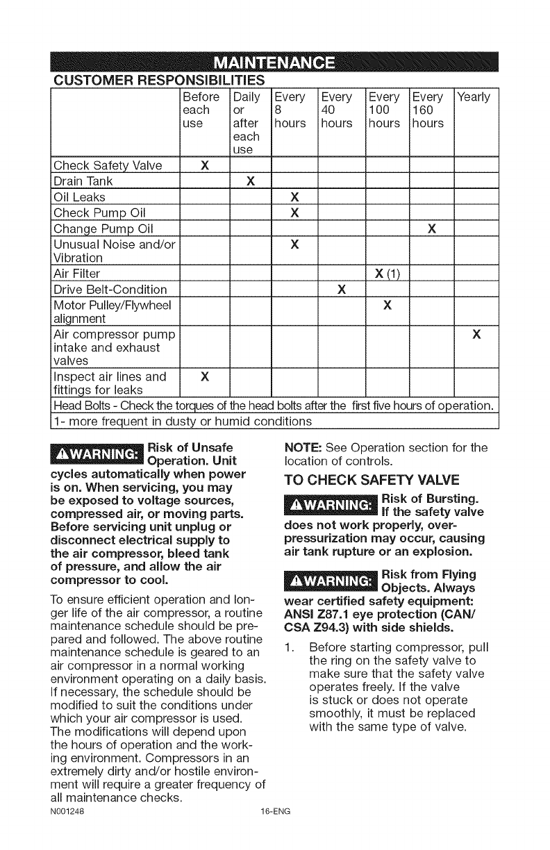
CUSTOMER RESPONSiBiLiTiES
Before Daily Every Every Every Every Yearly
each or 8 40 100 160
use after hours hours ihours hours
each
use
Check Safety Valve X
Drain Tank X
Oil Leaks X
Check Pump Oil X
Change Pump Oil X
Unusual Noise and/or X
Vibration
Air Filter X (1)
Drive Belt-Condition X
Motor Pulley/Flywheel X
alignment
Air compressor pump X
intake and exhaust
valves
Inspect air lines and X
fittings for leaks
Head Bolts - Check the torques of the head bolts after the first five hours of operation.
il- more frequent in dusty or humid conditions
_Risk of Unsafe
__ Operation. Unit
cycles automatically when power
is on. When servicing, you may
be exposed to voltage sources,
compressed air, or moving parts.
Before servicing unit unplug or
disconnect electrical supply to
the air compressor, bleed tank
of pressure, and allow the air
compressor to cool.
To ensure efficient operation and lon-
ger life of the air compressor, a routine
maintenance schedule should be pre-
pared and followed. The above routine
maintenance schedule is geared to an 1.
air compressor in a normal working
environment operating on a daily basis.
If necessary, the schedule should be
modified to suit the conditions under
which your air compressor is used.
The modifications will depend upon
the hours of operation and the work-
ing environment. Compressors in an
extremely dirty and/or hostile environ-
ment will require a greater frequency of
all maintenance checks.
N001248 16-ENG
NOTE: See Operation section for the
location of controls.
TO CHECK SAFETY VALVE
_Risk of Bursting.
__ if the safety valve
does not work properly, over=
pressurization may occur, causing
air tank rupture or an explosion.
Risk from Flying
Objects. Always
wear certified safety equipment:
ANSI Z87.1 eye protection (CAN/
CSA Z94.3} with side shields.
Before starting compressor, pull
the ring on the safety valve to
make sure that the safety valve
operates freely. If the valve
is stuck or does not operate
smoothly, it must be replaced
with the same type of valve.
TO DRAIN TANK
Risk of Unsafe
Operation. Risk
from noise. Air tanks contain high
pressure air. Keep face and other
body parts away from outlet of
drain. Use ANSi Z87.1 eye protection
(CAN/CSA Z94.3) when draining as
debris can be kicked up into face.
Use ear protection (ANSi S12.6
($3.19) hearing protection) as air flow
noise is loud when draining.
NOTE: Operation of the air compres-
sor will cause condensation to build up
in the air tank. Always drain tank on a
washable surface or in a suitable con-
tainer to prevent damaging or staining
surfaces.
1. Set the On/Auto/Off lever to "Off".
2. Close the globe valve.
3. Remove the air tool or accessory.
4. Open the globe valve and allow
the air to slowly bleed from the air
tank until tank pressure is approxi-
mately 20 psi.
5. Close the globe valve.
6. Drain water from air tank by open-
ing drain valve on bottom of tank.
Risk of Bursting.
Water will condense
in the air tank. if not drained, water
will corrode and weaken the air tank
causing a risk of air tank rupture.
Risk of Property
Damage. Drain
water from air tank may contain oil
and rust which can cause stains.
7. After the water has been drained,
close the drain valve. The air com-
pressor can now be stored.
NOTE: If drain valve is plugged,
release all air pressure. The valve can
then be removed, cleaned, then rein-
stalled.
OIL
Use air compressor
oil only. Multi-
weight automotive engine oils like
10W30 should not be use in air
compressors. They leave carbon
deposits on critical components,
thus reducing performance and
compressor life.
NOTE: Use 30W compressor oil or a
heavy duty SAE 30W, non-detergent,
SF grade or better oil DO NOT use
multi-weight automotive engine oils,
they will reduce compressor life. Under
extreme winter condition use SAE-10
weight oil.
NOTE: Crankcase oil capacity is
approximately 16 fluid ounces
(0.47 L).
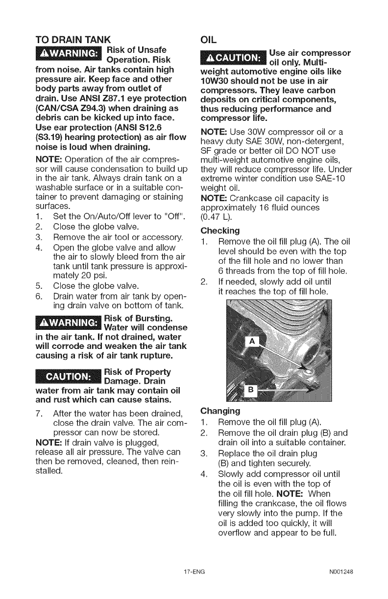
Checking
1. Remove the oil fill plug (A). The oil
level should be even with the top
of the fill hole and no lower than
6 threads from the top of fill hole.
2. If needed, slowly add oil until
it reaches the top of fill hole.
Changing
1. Remove the oil fill plug (A).
2. Remove the oil drain plug (B) and
drain oil into a suitable container.
3. Replace the oil drain plug
(B) and tighten securely.
4. Slowly add compressor oil until
the oil is even with the top of
the oil fill hole. NOTE: When
filling the crankcase, the oil flows
very slowly into the pump. If the
oil is added too quickly, it will
overflow and appear to be full.
17-ENG N001248
Risk of unsafe
operation. Overfilling with oil will
cause premature compressor failure.
Do not overfill.
5. Replace oil fill plug (A)
and tighten securely.
AIR FILTER = INSPECTION AND
REPLACEMENT
Hot surfaces.
Risk of burn.
Compressor heads are exposed
when filter cover is removed.
Allow compressor to cool prior to
servicing.
Keep the air filter
clean at all times. Do
not operate the air compressor with
the air filter removed.
A dirty air filter will not allow the com-
pressor to operate at full capacity.
Keep the air filter clean at all times.
1. Remove
the air filter
cover.
2. Remove
the air filter
from filter
cover.
IMPORTANT:
Do not oper-
ate the compressor with the air filter
removed.
3. Place new air filter into filter cover.
Refer to the Repair Parts for the
correct part number.
4. Replace air filter cover and lock
into place.
BELT = REPLACEMENT
Risk of personal
injury. Serious injury or damage
may occur if parts of the body or
loose items get caught in moving
parts. Never operate the outfit
with the belt guard removed. The
belt guard should be removed only
when the air compressor power is
disconnected.
1. Turn air compressor off, lock out
the power supply, and relieve all
air pressure from the air tank.
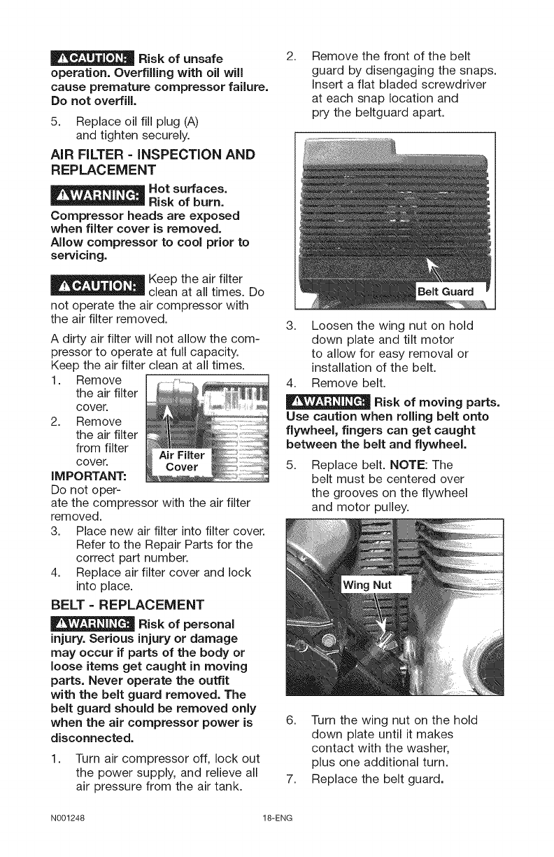
2. Remove the front of the belt
guard by disengaging the snaps.
Insert a flat bladed screwdriver
at each snap location and
pry the beltguard apart.
3. Loosen the wing nut on hold
down plate and tilt motor
to allow for easy removal or
installation of the belt.
4. Remove belt.
Risk of moving parts.
Use caution when rolling belt onto
flywheel, fingers can get caught
between the belt and flywheel.
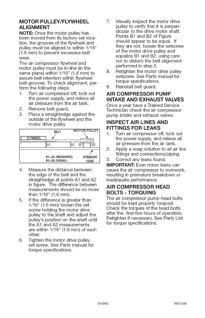
5. Replace belt. NOTE: The
belt must be centered over
the grooves on the flywheel
and motor pulley.
6. Turn the wing nut on the hold
down plate until it makes
contact with the washer,
plus one additional turn.
7. Replace the belt guard.
N001248 18-ENG
MOTOR PULLEY/FLYWHEEL
ALIGNMENT
NOTE: Once the motor pulley has
been moved from its factory set loca-
tion, the grooves of the flywheel and
pulley must be aligned to within 1/16"
(1.6 mm) to prevent excessive belt
wear.
The air compressor flywheel and
motor pulley must be in-line (in the
same plane) within 1/16" (1.6 mm) to
assure belt retention within flywheel
belt grooves. To check alignment, per-
form the following steps:
1. Turn air compressor off, lock out
the power supply, and relieve all
air pressure from the air tank.
2. Remove belt guard.
3. Place a straightedge against the
outside of the flywheel and the
motor drive pulley.
BELT MOTOR PULLEY I
AI= A2 (MEASURED) STRAIGHT
BI= B2 (V SUAL) EDGE
4. Measure the distance between
the edge of the belt and the
straightedge at points A1 and A2
in figure. The difference between
measurements should be no more
than 1/16" (1.6 mm).
5. If the difference is greater than
1/16" (1.6 mm) loosen the set
screw holding the motor drive
pulley to the shaft and adjust the
pulley's position on the shaft until
the A1 and A2 measurements
are within 1/16" (1.6 mm) of each
other.
6. Tighten the motor drive pulley
set screw. See Parts manual for
torque specifications.
7. Visually inspect the motor drive
pulley to verify that it is perpen-
dicular to the drive motor shaft.
Points B1 and B2 of Figure
should appear to be equal. If
they are not, loosen the setscrew
of the motor drive pulley and
equalize B1 and B2, using care
not to disturb the belt alignment
performed in step 2.
8. Retighten the motor drive pulley
setscrew. See Parts manual for
torque specifications.
9. Reinstall belt guard.
AiR COMPRESSOR PUMP
iNTAKE AND EXHAUST VALVES
Once a year have a Trained Service
Technician check the air compressor
pump intake and exhaust valves.
iNSPECT AIR LINES AND
FiTTiNGS FOR LEAKS
1. Turn air compressor off, lock out
the power supply, and relieve all
air pressure from the air tank.
2. Apply a soap solution to all air line
fittings and connections/piping.
3. Correct any leaks found.
iMPORTANT: Even minor leaks can
cause the air compressor to overwork,
resulting in premature breakdown or
inadequate performance.
AIR COMPRESSOR HEAD
BOLTS = TORQUING
The air compressor pump head bolts
should be kept properly torqued.
Check the torques of the head bolts
after the first five hours of operation.
Retighten if necessary. See Parts List
for torque specifications.
19-ENG N001248
ALL MAINTENANCE AND REPAIR
OPERATIONS NOT LISTED MUST BE
PERFORMED BY TRAINED SERVICE
TECHNICIAN.
Risk of Unsafe
Operation. Unit
cycles automatically when power
is on. When servicing, you may
be exposed to voltage sources,
compressed air, or moving parts.
Before servicing unit unplug or
disconnect electrical supply to
the air compressor, bleed tank
of pressure, and allow the air
compressor to cool.
TO REPLACE OR CLEAN CHECK
VALVE
1. Release all air pressure from air
tank. See "To Drain Tank" in the
Maintenance section.
2. Turn air compressor off, lock out
the power supply, and relieve all
air pressure from the air tank.
3. Using an adjustable wrench loos-
en outlet tube nut at air tank and
pump. Carefully move outlet tube
away from check valve.
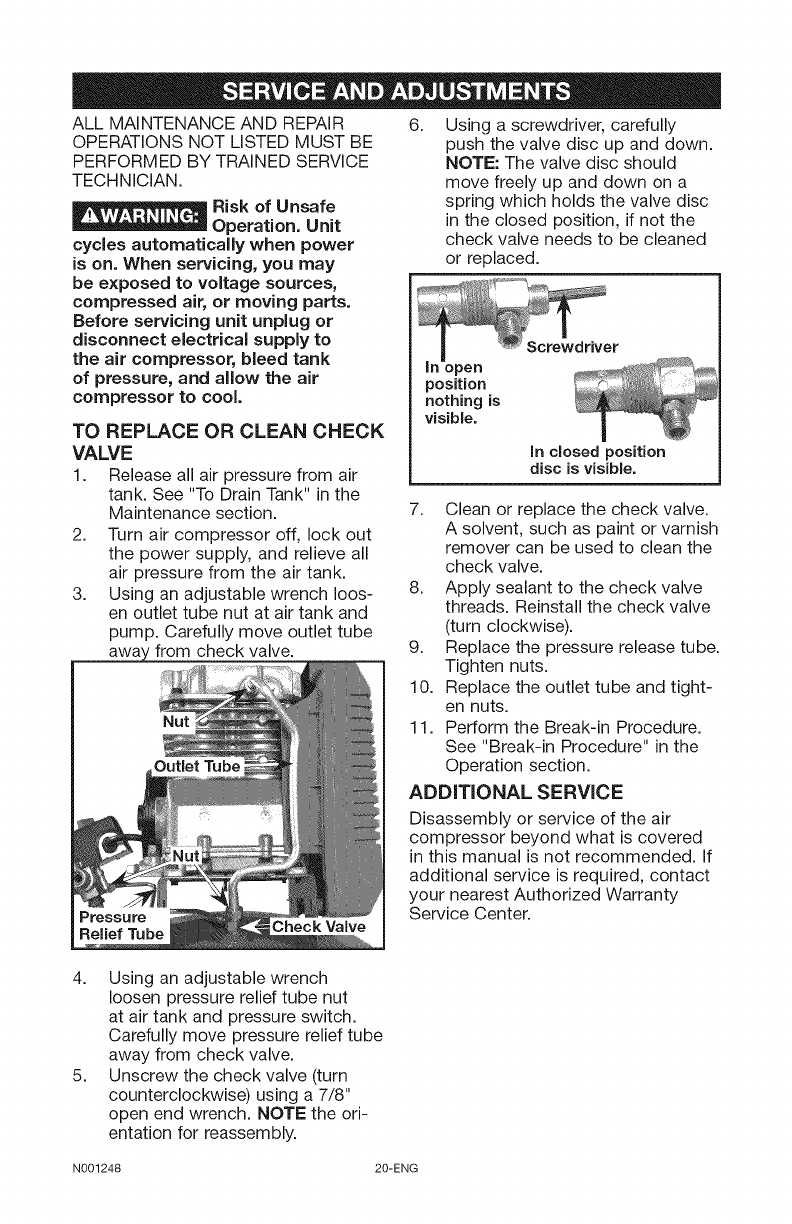
6. Using a screwdriver, carefully
push the valve disc up and down.
NOTE: The valve disc should
move freely up and down on a
spring which holds the valve disc
in the closed position, if not the
check valve needs to be cleaned
or replaced.
position
nothing is
visible.
in closed position
disc is visible.
7. Clean or replace the check valve.
A solvent, such as paint or varnish
remover can be used to clean the
check valve.
8. Apply sealant to the check valve
threads. Reinstall the check valve
(turn clockwise).
9. Replace the pressure release tube.
Tighten nuts.
10. Replace the outlet tube and tight-
en nuts.
11. Perform the Break-in Procedure.
See "Break-in Procedure" in the
Operation section.
ADDITIONAL SERVICE
Pressure
Relief Tube
Disassembly or service of the air
compressor beyond what is covered
in this manual is not recommended, if
additional service is required, contact
your nearest Authorized Warranty
Service Center.
4. Using an adjustable wrench
loosen pressure relief tube nut
at air tank and pressure switch.
Carefully move pressure relief tube
away from check valve.
5. Unscrew the check valve (turn
counterclockwise) using a 7/8"
open end wrench. NOTE the ori-
entation for reassembly.
N001248 20-ENG
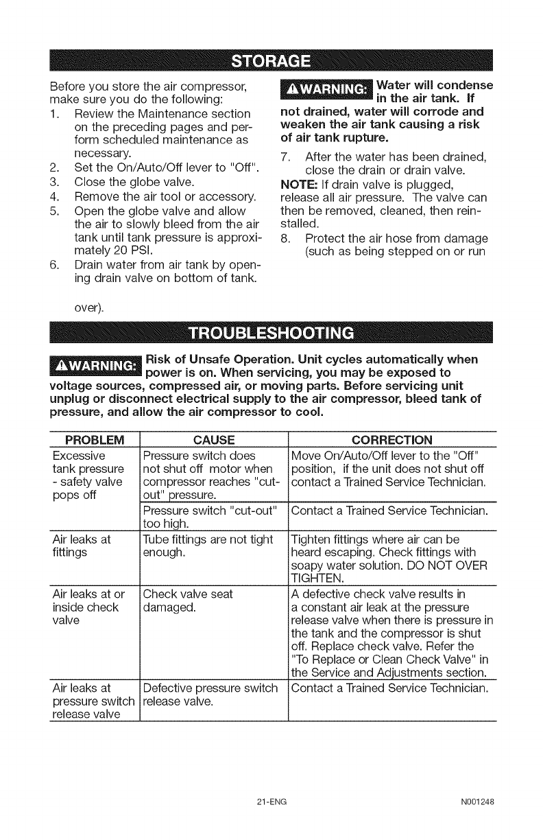
Before you store the air compressor,
make sure you do the following:
1. Review the Maintenance section
on the preceding pages and per-
form scheduled maintenance as
necessary.
2. Set the On/Auto/Off lever to "Off".
3. Close the globe valve.
4. Remove the air tool or accessory.
5. Open the globe valve and allow
the air to slowly bleed from the air
tank until tank pressure is approxi-
mately 20 PSI.
6. Drain water from air tank by open-
ing drain valve on bottom of tank.
E__ ater will condense
in the air tank. if
not drained, water will corrode and
weaken the air tank causing a risk
of air tank rupture.
7. After the water has been drained,
close the drain or drain valve.
NOTE: If drain valve is plugged,
release all air pressure. The valve can
then be removed, cleaned, then rein-
stalled.
8. Protect the air hose from damage
(such as being stepped on or run
over).
Risk of Unsafe Operation. Unit cycles automatically when
power is on. When servicing, you may be exposed to
voltage sources, compressed air, or moving parts. Before servicing unit
unplug or disconnect electrical supply to the air compressor, bleed tank of
pressure, and allow the air compressor to cool.
PROBLEM
Excessive
tank pressure
- safety valve
pops off
Air leaks at
fittings
Air leaks at or
inside check
valve
Air leaks at
pressure switch
release valve
CAUSE
Pressure switch does
not shut off motor when
compressor reaches "cut-
_ressure.
Pressure switch "cut-out"
too high.
Tube fittings are not tight
enough.
Check valve seat
damaged.
Defective pressure switch
release valve.
CORRECTION
Move On/Auto/Off lever to the "Off"
position, if the unit does not shut off
contact a Trained Service Technician.
Contact a Trained Service Technician.
Tighten fittings where air can be
heard escaping. Check fittings with
soapy water solution. DO NOT OVER
TIGHTEN.
A defective check valve results in
a constant air leak at the pressure
release valve when there is pressure in
the tank and the compressor is shut
off. Replace check valve. Refer the
"To Replace or Clean Check Valve" in
the Service and Adjustments section.
Contact a Trained Service Technician.
21-ENG N001248
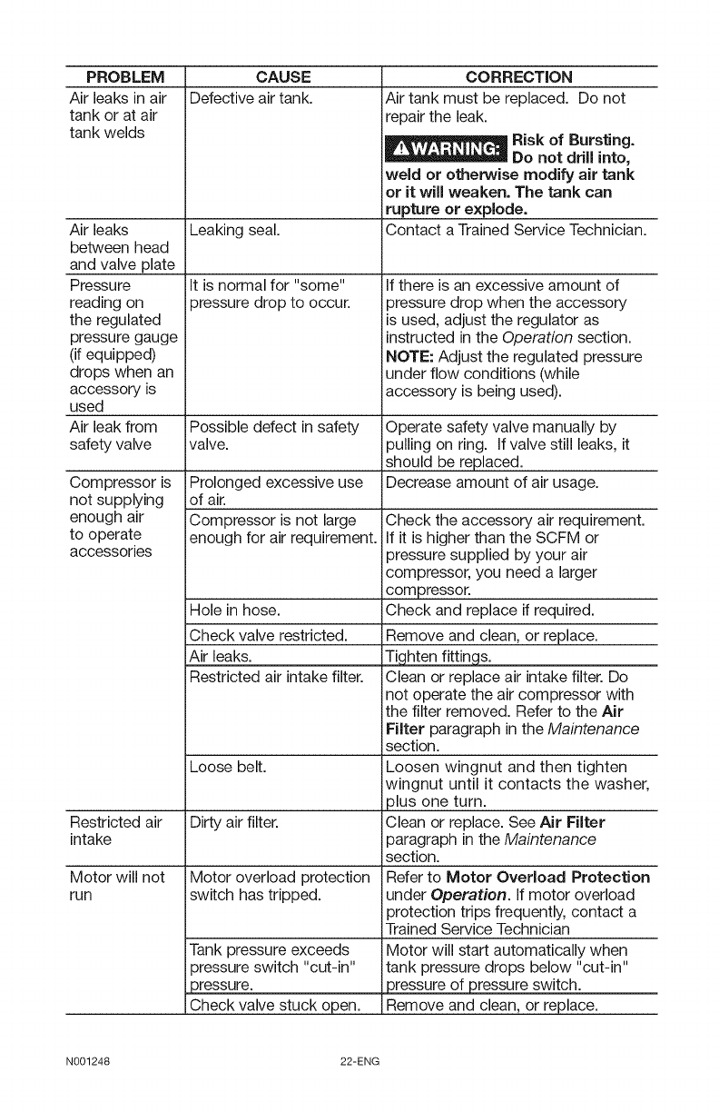
PROBLEM
Air leaks in air
tank or at air
tank welds
Air leaks
between head
and valve plate
Pressure
reading on
the regulated
pressure gauge
(if equipped)
drops when an
accessory is
used
Air leak from
safety valve
Compressor is
not supplying
enough air
to operate
accessories
CAUSE
Defective air tank.
Leaking seal.
It is normal for "some"
3ressure drop to occur.
CORRECTION
Air tank must be replaced. Do not
repair the leak.
Risk of Bursting.
Do not drill into,
weld or otherwise modify air tank
or it will weaken. The tank can
rupture or explode.
Contact a Trained Service Technician.
If there is an excessive amount of
pressure drop when the accessory
is used, adjust the regulator as
instructed in the Operation section.
NOTE: Adjust the regulated pressure
under flow conditions (while
accessory is being used).
Possible defect in safety Operate safety valve manually by
valve, pulling on ring. If valve still leaks, it
should be replaced.
Decrease amount of air usage.Prolonged excessive use
of air.
Compressor is not large
enough for air requirement.
Hole in hose.
Check valve restricted.
Air leaks.
Restricted air intake filter.
Loose belt.
Restricted air Dirty air filter.
intake
Motor will not Motor overload protection
run switch has tripped.
Tank pressure exceeds
3ressure switch "cut-in"
3ressure.
Check valve stuck open.
Check the accessory air requirement.
If it is higher than the SCFM or
pressure supplied by your air
compressor, you need a larger
compressor.
Check and replace if required.
Remove and clean, or replace.
Ti hten fittin s.
Clean or replace air intake filter. Do
not operate the air compressor with
the filter removed. Refer to the Air
Filter paragraph in the Maintenance
section.
Loosen wingnut and then tighten
wingnut until it contacts the washer,
plus one turn.
Clean or replace. See Air Filter
paragraph in the Maintenance
section.
Refer to Motor Overload Protection
under Operation. If motor overload
protection trips frequently, contact a
Trained Service Technician
Motor will start automatically when
tank pressure drops below "cut-in"
pressure of pressure switch.
Remove and clean, or replace.
N001248 22-ENG
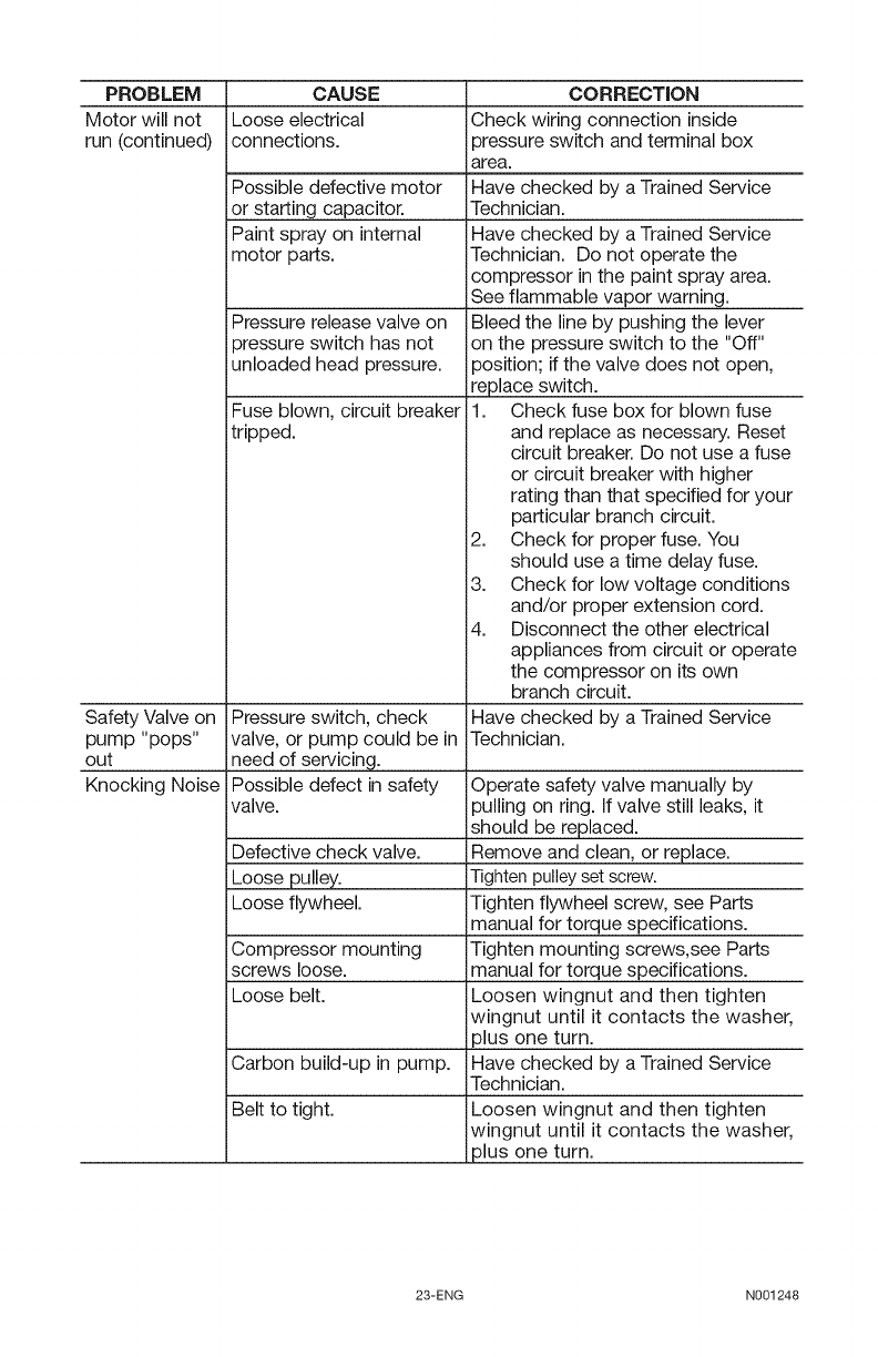
PROBLEM CAUSE
Motor will not Loose electrical
run (continued) connections.
Possible defective motor
or starting capacitor.
Paint spray on internal
motor parts.
Safety Valve on
pump "pops"
out
Knocking Noise
Pressure release valve on
3ressure switch has not
Jnloaded head pressure.
Fuse blown, circuit breaker
tripped.
Pressure switch, check
valve, or pump could be in
need of servicing.
Possible defect in safety
valve.
Defective check valve.
Loose pulley.
Loose flywheel.
Compressor mounting
screws loose.
Loose belt.
Carbon build-up in pump.
Belt to tight.
CORRECTION
Check wiring connection inside
pressure switch and terminal box
area.
Have checked by a Trained Service
Technician.
Have checked by a Trained Service
Technician. Do not operate the
compressor in the paint spray area.
See flammable vapor warning.
Bleed the line by pushing the lever
on the pressure switch to the "Off"
position; if the valve does not open,
replace switch.
Check fuse box for blown fuse
and replace as necessary. Reset
circuit breaker. Do not use a fuse
or circuit breaker with higher
rating than that specified for your
particular branch circuit.
Check for proper fuse. You
should use a time delay fuse.
3. Check for low voltage conditions
and/or proper extension cord.
4. Disconnect the other electrical
appliances from circuit or operate
the compressor on its own
branch circuit.
Have checked by a Trained Service
Technician.
Operate safety valve manually by
pulling on ring. If valve still leaks, it
should be replaced.
Remove and clean, or replace.
Tighten pulleyset screw.
Tighten flywheel screw, see Parts
manual for torque specifications.
Tighten mounting screws,see Parts
manual for torque specifications.
Loosen wingnut and then tighten
wingnut until it contacts the washer,
plus one turn.
Have checked by a Trained Service
Technician.
Loosen wingnut and then tighten
wingnut until it contacts the washer,
plus one turn.
23-ENG N001248
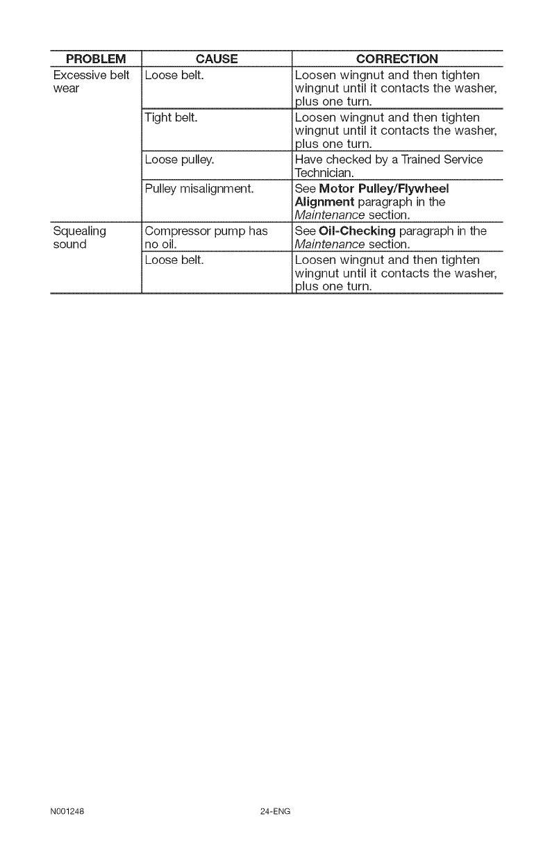
PROBLEM
Excessive belt
wear
CAUSE
Loose belt.
Tight belt.
Loose pulley.
Pulley misalignment.
Squealing Compressor pump has
sound no oil.
Loose belt.
CORRECTION
Loosen wingnut and then tighten
wingnut until it contacts the washer
plus one turn.
Loosen wingnut and then tighten
wingnut until it contacts the washer
plus one turn.
Have checked by a Trained Service
Technician.
See Motor Pulley/Flywheel
Alignment paragraph in the
Maintenance section.
See Oil=Checking paragraph in the
Maintenance section.
Loosen wingnut and then tighten
wingnut until it contacts the washer
lus one turn.
N001248 24-ENG
25-ENG N001248
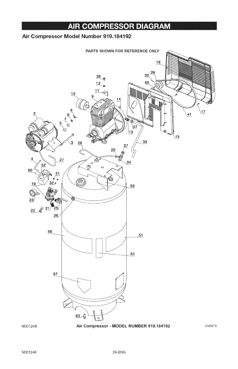
Air Compressor Model Number 919.184192
10
PARTS SHOWN FOR REFERENCE ONLY
16
29
30
4
6O
8
33
19 59
22 _ 21
56 51
53
57
N001248 Air Compressor - MODEL NUMBER 919.184192 03/08TS
N001248 26-ENG
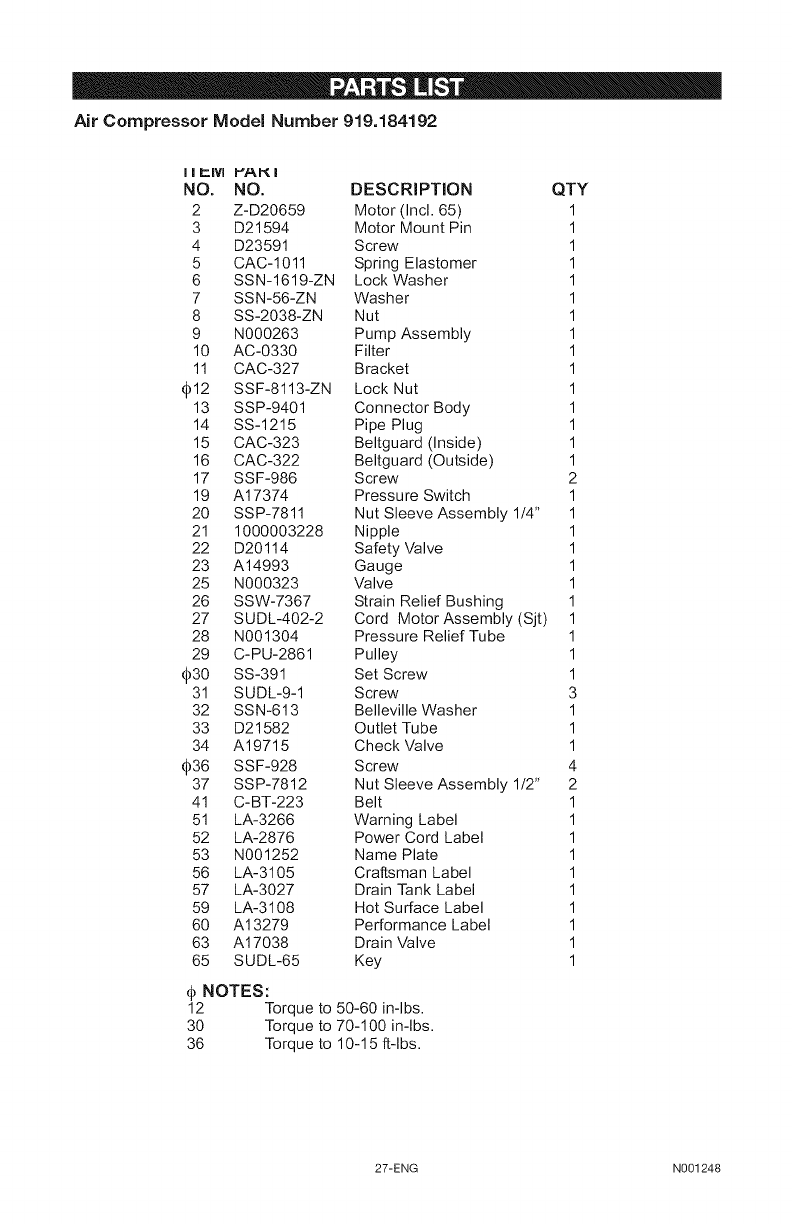
Air Compressor Model Number 919.184192
NO, NO. DESCRIPTION QTY
2 Z-D20659 Motor (incl. 65) 1
3 D21594 Motor Mount Pin 1
4 D23591 Screw 1
5 CAC-1011 Spring Elastomer 1
6 SSN-1619-ZN Lock Washer 1
7 SSN-56-ZN Washer 1
8 SS-2038-ZN Nut 1
9 N000263 Pump Assembly 1
10 AC-0330 Filter 1
11 CAC-327 Bracket 1
_12 SSF-8113-ZN Lock Nut 1
13 SSP-9401 Connector Body 1
14 SS-1215 Pipe Plug 1
15 CAC-323 Beltguard (inside) 1
16 CAC-322 Beltguard (Outside) 1
17 SSF-986 Screw 2
19 A17374 Pressure Switch 1
20 SSP-7811 Nut Sleeve Assembly 1/4" 1
21 1000003228 Nipple 1
22 D20114 Safety Valve 1
23 A14993 Gauge 1
25 N000323 Valve 1
26 SSW-7367 Strain Relief Bushing 1
27 SUDL-402-2 Cord Motor Assembly (Sjt) 1
28 N001304 Pressure Relief Tube 1
29 C-PU-2861 Pulley 1
_30 SS-391 Set Screw 1
31 SUDL-9-1 Screw 3
32 SSN-613 Belleville Washer 1
33 D21582 Outlet Tube 1
34 A19715 Check Valve 1
_36 SSF-928 Screw 4
37 SSP-7812 Nut Sleeve Assembly 112" 2
41 C-BT-223 Belt 1
51 LA-3266 Warning Label 1
52 LA-2876 Power Cord Label 1
53 N001252 Name Plate 1
56 LA-3105 Craftsman Label 1
57 LA-3027 Drain Tank Label 1
59 LA-3108 Hot Surface Label 1
60 A13279 Performance Label 1
63 A17038 Drain Valve 1
65 SUDL-65 Key 1
@NOTES:
12 Torque to 50-60 in-lbs.
30 Torque to 70-100 in-lbs.
36 Torque to 10-15 ft-lbs.
27-ENG N001248
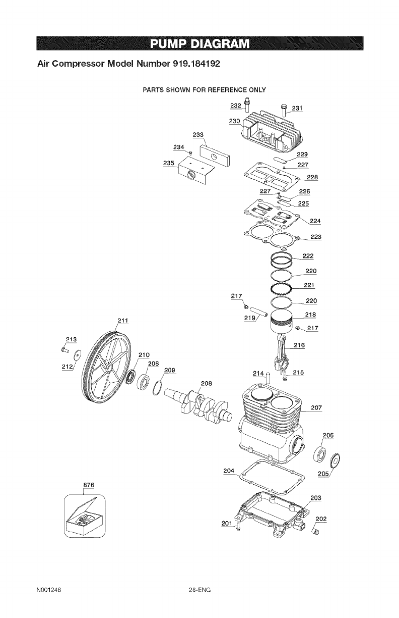
Air Compressor Model Number 919.184192
PARTS SHOWN FOR REFERENCE ONLY
232_ 231
233
234 "_ 229
235 227
228
211
213 _
/E_ i _i)l_o
212_) .....................209
876
208
2O4
201
217 0 221
C"J-- _°
L..j
216
214 215
207
203
202
N001248 28-ENG
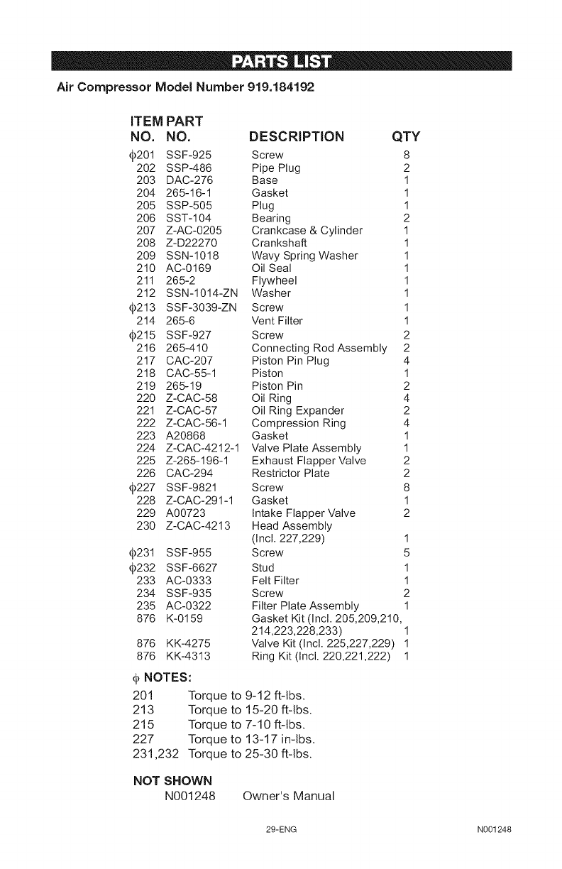
Air Compressor Model Number 919.184192
iTEM PART
NO. NO. DESCRiPTiON QTY
_201 SSF-925 Screw 8
202 SSP-486 Pipe Plug 2
203 DAC-276 Base 1
204 265-16-1 Gasket 1
205 SSP-505 Plug 1
206 SST-104 Bearing 2
207 Z-AC-0205 Crankcase & Cylinder 1
208 Z-D22270 Crankshaft 1
209 SSN-1018 Wavy Spring Washer 1
210 AC-0169 Oil Seal 1
211 265-2 Flywheel 1
212 SSN-1014-ZN Washer 1
_213 SSF-3039-ZN Screw 1
214 265-6 Vent Filter 1
_215 SSF-927 Screw 2
216 265-410 Connecting Rod Assembly 2
217 CAC-207 Piston Pin Plug 4
218 CAC-55-1 Piston 1
219 265-19 Piston Pin 2
220 Z-CAC-58 Oil Ring 4
221 Z-CAC-57 Oil Ring Expander 2
222 Z-CAC-56-1 Compression Ring 4
223 A20868 Gasket 1
224 Z-CAC-4212-1 Valve Plate Assembly 1
225 Z-265-196-1 Exhaust Flapper Valve 2
226 CAC-294 Restrictor Plate 2
_227 SSF-9821 Screw 8
228 Z-CAC-291-1 Gasket 1
229 A00723 Intake Flapper Valve 2
230 Z-CAC-4213 Head Assembly
(Incl. 227,229) 1
_231 SSF-955 Screw 5
_232 SSF-6627 Stud 1
233 AC-0333 Felt Filter 1
234 SSF-935 Screw 2
235 AC-0322 Filter Plate Assembly 1
876 K-0159 Gasket Kit (Incl. 205,209,210,
214,223,228,233) 1
876 KK-4275 Valve Kit (Incl. 225,227,229) 1
876 KK-4313 Ring Kit (Incl. 220,221,222) 1
@NOTES:
201 Torque to 9-12 ft-tbs.
213 Torque to 15-20 ft-tbs.
215 Torque to 7-10 ft-tbs.
227 Torque to 13-17 in-tbs.
231,232 Torque to 25-30 ft-tbs.
NOT SHOWN
N001248 Owner's Manual
29-ENG N001248
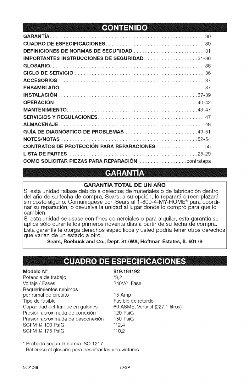
GARANTJA ....................................................... 30
CUADRO DE ESPECIFICACIONES ................................... 30
DEFINICIONES DE NORMAS DE SEGURIDAD ......................... 31
IMPORTANTES INSTRUCCIONES DE SEGURIDAD ................... 31-36
GLOSARIO ....................................................... 36
ClCLO DE SERVlCIO .............................................. 36
ACCESORIOS ................................................... 37
ENSAMBLADO ................................................... 37
INSTALACl6N .................................................. 37-39
OPERACl6N ................................................... 40-42
MANTENIMIENTO ............................................... 43-47
SERVlCIOS Y REGULACIONES ...................................... 47
ALMACENAJE .................................................... 48
GUJA DE DIAGN6STICO DE PROBLEMAS .......................... 49-51
NOTES/NOTAS ................................................. 52-54
CONTRATOS DE PROTECCl6N PARA REPARACIONES ................. 55
MSTA DE PARTES .............................................. 25-29
COMO SOMCITAR PIEZAS PARA REPARACl6N ................. contratapa
GARANTJA TOTAL DE UN ANO
Siesta unidad fallase debido a defectos de materiales o de fabricaci6n dentro
del a_o de su fecha de compra, Sears, a su opci6n, Io reparara o reemplazara
sin costo alguno. Comuniquese con Sears al 1-800-4-MY-HOME ® para coordi-
nat su reparaci6n, o devuelva la unidad al lugar donde Io compr6 para que Io
cambien.
Siesta unidad se usase con fines comerciales o para alquiler, esta garantia se
aplica s61o durante los primeros noventa dias a partir de su fecha de compra.
Esta garantia le otorga derechos especificos y usted podria tenet otros derechos
que varian de un estado a otro.
Sears, Roebuck and Co., Dept. 817WA, Hoffman Estates, IL 60179
Modelo N°
Potencia de trabajo
Voltaje /Fases
Requerimientos minimos
per ramal de circuito
Tipo de fusible
Capacidad del tanque en galones
Presi6n aproximada de conexi6n
Presi6n aproximada de desconexi6n
SCFM @ 100 PsiG
SCFM @ 175 PsiG
919.184192
*3,2
240V/1 Fase
15 Amp
Fusible de retardo
60 ASME, Vertical (227,1 litros)
120 PsiG
150 PsiG
"12,4
"10,2
* Probado segQn la norma ISO 1217
Refi6rase al glosario para descifrar las abreviaturas.
N001248 30-SP
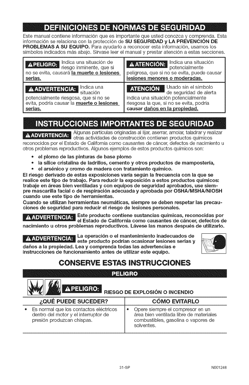
Este manual contiene informaci6n que es importante que usted conozca y comprenda. Esta
informaci6n se relaciona con la protecci6n de SU SEGURIDAD y LA PREVENCION DE
PROBLEMAS A SU EQUIPO. Para ayudarlo a reconocer esta informaci6n, usamos los
simbolos indicados mAs abajo. Sirvase leer el manual y prestar atenci6n a estas secciones.
Indica una situaci6n de
riesgo inminente, que si
no se evita, causarA la muerte o lesiones
serias.
Indica una
situaci6n
potencialmente riesgosa, que si no se
evita, podria causar la muerte o lesiones
serias.
, , , =, Indica una situaci6n
potencialmente
peligrosa, que si no se evita, puede causar
lesiones menores o moderadas.
_ Usado sin el simbolo
de seguridad de alerta
indica una situaci6n potencialmente
riesgosa la que, si no se evita, podria
causar da_os en la propiedad.
_ Algunas particulas originadas al lijar, aserrar, amolar, taladrar y realizar
otras actividades de construcci6n contienen productos quimicos
reconocidos por el Estado de California como causantes de cancer, defectos de nacimiento u
otros problemas reproductivos. AIgunos ejemplos de estos productos quimicos son:
=el plorno de las pinturas de base plorno
=la snice cristalina de ladriUos, cernento y otros productos de mamposterfa,
= el ars_nico y crorno de rnadera con tratamiento quirnico.
El riesgo derivado de estas exposiciones varia seg_n la frecuencia con la que se
realice este tipo de trabajo. Para reducir la e×posici6n aestos productos quimicos:
trabaje en areas bien ventiladas y con equipos de seguridad aprobados, use siem=
pre mascarilla facial ode respiracibn adecuada y aprobada por OSHA/MSHA/NIOSH
cuando use este tipo de herramientas.
Cuando se utilizan herrarnientas neurn_ticas, siernpre se deben respetar las precau=
clones de seguridad para reducir el riesgo de lesiones personales.
Este producto contiene sustancias qufrnicas, reconocidas por
el Estado de California corno causantes de c_ncer, defectos de
nacimiento u otros problernas reproductivos. L_vese las manes despu_s de utilizarlo.
La operaci6n o el rnantenirniento inadecuados de _:A
este producto podrian ocasionar lesiones serias y
da_os a la propiedad. Lea y cornprenda todas las advertencias e
instrucciones de funcionamiento antes de utilizar este equipo.
CONSERVE ESTAS INSTRUCCIONES
_RIESGO DE EXPLOSION 0 INCENDIO
&QU! _PUEDE SUCEDER? iCOMO EVITARLO
= Es normal que los contactos el6ctricos = Opere siempre el compresor en un
dentro del motor y el interruptor de area bien ventilada libre de materiales
presi6n produzcan chispas, combustibles, gasolina o vapores de
solventes.
31-SP N001248
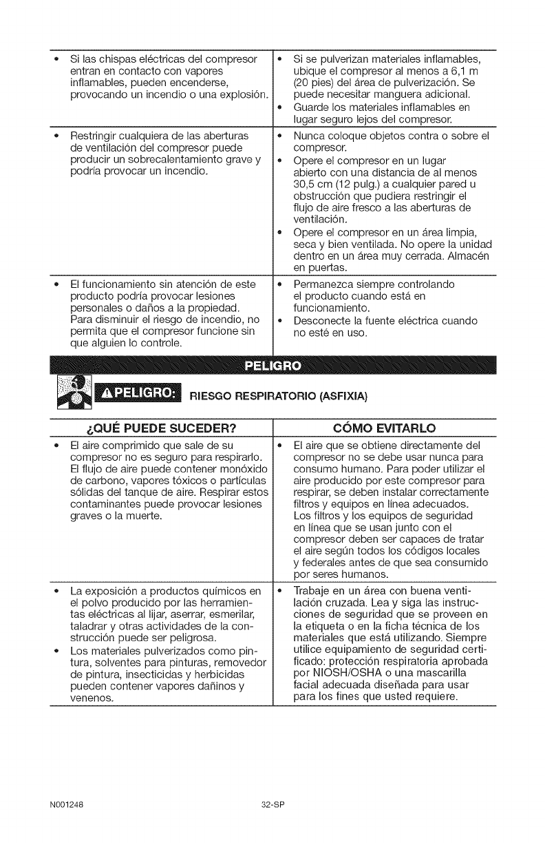
Si las chispas el_ctricas del compresor
entran en contacto con vapores
inflamables, pueden encenderse,
provocando un incendio o una explosi6n.
Restringir cualquiera de las aberturas
de ventilaci6n del compresor puede
producir un sobrecalentamiento grave y
podria provocar un incendio.
• El funcionamiento sin atenci6n de este
producto podria provocar lesiones
personales o da_os a la propiedad.
Para disminuir el riesgo de incendio, no
permita que el compresor funcione sin
que alguien Io controle.
• Si se pulverizan materiales inflamables,
ubique el compresor al menos a 6,1 m
(20 pies) del Area de pulverizaci6n. Se
puede necesitar manguera adicional.
• Guarde los materiales inflamables en
lugar seguro lejos del compresor.
Nunca coloque objetos contra o sobre el
compresor.
Opere el compresor en un lugar
abierto con una distancia de al menos
30,5 cm (12 pulg.) a cualquier pared u
obstrucci6n que pudiera restringir el
flujo de aire fresco a las aberturas de
ventilaci6n.
Opere el compresor en un Area limpia,
seca y bien ventilada. No opere la unidad
dentro en un Area muy cerrada. AImac6n
en puertas.
Permanezca siempre controlando
el producto cuando estA en
funcionamiento.
• Desconecte la fuente el6ctrica cuando
no est6 en uso.
D ®
__ RIESGO RESPIRATORIO (ASFIXIA)
COMO EVITARLO
• •
&QUE PUEDE SUCEDER?
El aire comprimido que sale de su
compresor no es seguro para respirarlo.
El flujo de aire puede contener mon6xido
de carbono, vapores t6xicos o particulas
s61idas del tanque de aire. Respirar estos
contaminantes puede provocar lesiones
graves o la muerte.
La exposicion a productos quimicos en
el polvo producido por las herramien-
tas el6ctricas al lijar, aserrar, esmerilar,
taladrar y otras actividades de la con-
strucci6n puede ser peligrosa.
Los materiales pulverizados como pin-
tura, solventes para pinturas, removedor
de pintura, insecticidas y herbicidas
pueden contener vapores da_inos y
venenos.
El aire que se obtiene directamente del
compresor no se debe usar nunca para
consumo humano. Para poder utilizar el
aire producido pot este compresor para
respirar, se deben instalar correctamente
filtros y equipos en linea adecuados.
Los filtros y los equipos de seguridad
en linea que se usan junto con el
compresor deben ser capaces de tratar
el aire segQn todos los c6digos locales
y federales antes de que sea consumido
pot seres humanos.
Trabaje en un Area con buena venti-
laci6n cruzada. Lea y siga las instruc-
ciones de seguridad que se proveen en
la etiqueta o en la ficha tecnica de los
materiales que esta utilizando. Siempre
utilJce equipamiento de segurJdad certi-
ficado: protecci6n respiratoria aprobada
per NIOSH/OSHA o una mascarilla
facial adecuada dise_ada para usar
para los fines que usted requiere.
N001248 32-SP
RIESGO DE LESION O DAl_lO A LA PROPIEDAD AL
TRANSPORTAR OALMACENAR LA UNIDAD
COMO EVITARLO
e
&QUF!: PUEDE SUCEDER?
Se puede producir una p@dida o
derrame de aceite, Io que podria
provocar peligro de incendio o
inhalaci6n, lesiones graves o la muerte.
Los derrames de aceite da_ar&n
alfombras, pintura u otras superficies de
vehiculos o remolques.
• Coloque siempre el compresor en un
tapete protector cuando Io transporte,
para proteger al vehiculo de da_os
por p@didas. Retire inmediatamente
el compresor del vehiculo una vez
que haya Ilegado a destino. Mantenga
siempre el compresor nivelado y nunca
Io coloque de costado.
= •
_I___ RIESGO DE EXPLOSION
Tanque de aire: El tanque de aire de su compresor de aire est& diseSado y puede tener
c6digo UM (para unidades con tanques de aire de m&s de 152 mm (6 pulgadas) de
di&metro) segen las normas de la ASME, Secci6n VIII, Div. 1. Todos los recipientes de
presi6n se deben inspeccionar cada dos aSos. Para encontrar al inspector de recipientes
de presion de su estado, busque en la Divisi6n Trabajo e Industrias de la secci6n guber-
namental de la guia telef6nica para obtener ayuda.
Las siguientes condiciones podrian Ilevar a un debilitamiento del tanque de aire, y provo-
car una explosi6n violenta del tanque:
&QUa: PUEDE SUCEDER? COMO EVITARLO
No drenar correctamente el agua • Drene el tanque diariamente o luego
condensada del tanque de aire, que de cada uso. Si un tanque de aire
provoca 6xido y adelgazamiento del presenta una p@dida, reemplAcelo
tanque de aire de acero, inmediatamente con un tanque nuevo o
reemplace todo el compresor.
Modificaciones o intento de reparaci6n
del tanque de aire.
Las modificaciones no autorizadas de
la v&lvula de seguridad o cualquier otro
componente que controle la presi6n del
tanque.
Nunca perfore, suelde o haga ninguna
modificaci6n al tanque de aire o a sus
elementos. Nunca intente reparar un
tanque de aire da_ado o con perdidas.
ReemplAcelo con un tanque de aire
nuevo.
El tanque esta dise_ado para soportar
determinadas presiones de operaci6n.
Nunca realice ajustes ni sustituya piezas
para cambiar las presiones de operaci6n
fijadas en la fabric&
Las vibraciones excesivas pueden • El compresor debe estar debidamente
debilitar el tanque de aire de un montado, Consulte las Instrucciones de
compresor estacionario y causar una "Anclaje" en Instalaci6n.
explosi6n.
Elementos yaccesorios:
•Exceder las indicaciones de presi6n
para las herramientas neumaticas, las
pistolas pulverizadoras, los accesorios
neumAticos, los neumaticos y otros
articulos inflables puede hacer que
exploten o revienten, y puede provocar
lesiones graves.
33-SP
Siga la recomendaci6n del fabricante del
equipo y nunca exceda el nivel maximo
de presi6n aceptable para los elementos.
Nunca utilice el compresor para infiar
objetos peque_os de baja presi6n, tales
como juguetes de ni_os, pelotas de
fOtbol o de basquetbol, etc.
N001248
_RIESGO DE DESCARGA ELECTRICA
COMO EVITARLO
• •
&QUE PUEDE SUCEDER?
Su compresor de aire funciona
con electricidad. Como cualquier
otro mecanismo que funciona
con electricidad, si no se Io utiliza
correctamente puede provocar
descargas el6ctricas.
Que personal no calificado intente
realizar reparaciones puede provocar
lesiones graves o muerte por
electrocuci6n.
Puesta a tierra: La no colocaci6n de
la puesta a tierra adecuada para este
producto puede provocar lesiones
graves o muerte por electrocuci6n.
"Consulte las Instrucciones de Conexi6n
a tierra" en "lnstalaci6n".
Nunca haga funcionar el compresor al
aire libre cuando esta Iloviendo o en
condiciones de humedad.
Nunca haga funcionar el compresor sin
las cubiertas de protecci6n o si estAn
da_adas.
Cualquier cableado el6ctrico o las
reparaciones requeridas para este
producto deben ser realizadas por
un centro de servicio de un centro de
mantenimiento autorizado de acuerdo
con los c6digos el6ctricos nacionales y
locales.
AsegOrese de que el circuito el6ctrico al
que se conecta el compresor suministre
la conexi6n a tierra adecuada, el voltaje
adecuado y el fusible de protecci6n
adecuado.
__ RIESGO DE OBJETOS DESPEDIDOS
= ®
COMO EVITARLO
o
&QU! _PUEDE SUCEDER?
La corriente de aire comprimido puede
provocar lesiones en los tejidos blandos
de la piel expuesta y puede impulsar
suciedad, astillas, particulas sueltas y
objetos pequefios a gran velocidad, que
pueden producir dafios en la propiedad y
lesiones personales.
• Utilice siempre equipo de seguridad
certificado: anteojos de seguridad ANSI
Z87.1 (CAN/CSA Z94.3) con protecci6n
lateral al usar el compresor.
Nunca apunte ninguna boquilla ni
pulverizador a ninguna parte del cuerpo
o a otras personas o animales.
Apague siempre el compresor y drene
la presi6n de la manguera de aire y del
tanque de aire antes de intentar hacer
mantenimiento, conectar herramientas o
accesorios.
= •
RIESGO DE SUPERFICIES CALIENTES
COMO EVITARLO
• •
&QUE PUEDE SUCEDER?
Tocar metal expuesto como el cabezal
del compresor, el cabezal del motor, el
escape del motor, o los tubos de salida
puede provocar quemaduras graves.
N001248 34-SP
Nunca toque ninguna parte metalica
expuesta del compresor durante
o inmediatamente despues de su
funcionamiento. El compresor continuarA
caliente durante varios minutos despues
de su funcionamiento.
No toque las cubiertas protectoras ni
intente realizar mantenimiento hasta que
la unidad se haya enfriado.
RIEsGoPeRPIEZASMOVlLES
COMe EVITARLO
• •
&QU# PUEDE SUCEDER?
Las piezas m6viles como la polea, el
volante y la correa pueden provocar
lesiones graves si entran en contacto
con usted o con sus ropas.
Nunca haga funcionar el compresor
sin los protectores o cubiertas o si los
mismos estan da_ados.
• Mantenga el cabello, la ropa y los
guantes alejados de las piezas en
movimiento. Las ropas holgadas, las
joyas o el cabello largo pueden quedar
atrapados en las piezas m6viles.
Los orificios de ventilaci6n pueden
cubrir piezas en movimiento, pot Io que
tambien se deben evitar.
Intentar hacer funcionar el compresor • Cualquier reparaci6n requerida pot
con partes da_adas o faltantes, o este producto debe ser realizada per
intentar reparar el compresor sin las un centro de servicio de un centro de
cubiertas protectoras puede exponerlo servicio autorizado.
a piezas m6viles Io que puede provocar
lesiones graves.
1__ RIESGO DE OPERACION INSEGURA
COMe EVITARLO
• •
&QUE PUEDE SUCEDER?
La operaci6n insegura de su compresor
de aire podria producir lesiones graves
o la muerte, a usted mismo o a otras
personas.
Revise y comprenda todas las
instrucciones y advertencias de este
manual.
Familiaricese con la operaci6n y los
controles del compresor de aire.
Mantenga el Area de operaciones libre
de personas, mascotas y obstaculos.
Mantenga a los ni_os alejados del
compresor de aire en todo momento.
No opere el producto cuando est6
cansado o bajo la influencia de alcohol
o drogas. Mant6ngase alerta en todo
momento.
• Nunca anule las caracteristicas de
seguridad de este producto.
• Equipe el &rea de operaciones con
un extintor de incendios.
No opere la maquina si faltan
piezas, si estas estan rotas o si no
son las autorizadas.
35-SP N001248
_RIESGO DE LESION POR LEVANTAR
MUCHO PESO
• _.QUI ePUEDE SUCEDER? • COMO EVITARLO
El intento de levantar un objeto muy I El compresor es demasiado pesado
pesado puede provocar lesiones graves, como para que Io levante una sola
persona. Consiga ayuda de otras
personas para evantar o.
RIESGO POR RUIDOS
_.QUI ePUEDE SUCEDER? •COMO EVITARLO
En determinadas condiciones y seg_n el Utilice siempre equipo de seguridad
periodo de uso, el ruido provocado per certificado: protecci6n auditiva ANSI
este producto puede originar p6rdida de $12.6 ($3.19).
audici6n.
CONSERVE ESTAS INSTRUCCIONES
PAPA FUTURAS CONSULTAS
Familiaricese con los siguientes t6rminos,
antes de operar la unidad:
CFM: (Cubic feet per minute) Pies cObicos
por minuto.
SCFM: (Stardard cubic feet per minute) Pies
cObicos estAndar per minuto; una unidad de
medida que permite medir la cantidad de
entrega de aire.
PsiG: (Pound per square inch) Libras per pul-
gada cuadrada.
C6digo de certificaci6n: Los productos
que usan una o mas de las siguientes
marcas: UL, CUL, ETL, CETL, han sido
evaluados por OSHA, laboratorios inde-
pendientes certificados en seguridad, y
reOnen los estandares suscriptos per los
laboratorios dedicados a la certificaci6n de
la seguridad.
Presi6n Aprox. de Conexi6n: Cuando el
motor esta apagado, la presi6n del tanque
de aire baja a medida que usted continua
usando su accesorio. Cuando la presi6n
del tanque baja al valor fijado en f_brica
como punto bajo, el motor volver_ a arran-
car autom_ticamente. La presi6n baja a la
cual el motor arranca automaticamente, se
llama presi6n "minima de corte".
Presi6n apro×, de desconexi6n: Cuando
un compresor de aire se enciende y
comienza a funcionar, la presi6n de aire en
el tanque comienza a aumentar. Aumenta
hasta un valor de presi6n alto fijado en
fabrica antes de que el motor autom&ti-
camente se apague protegiendo a su
tanque de aire de presiones mas altas que
su capacidad. La presi6n alta a la cual el
motor se apaga se llama presi6n "m&xima
de corte"o
Rarnal: Circuito el6ctrico que transporta
electricidad desde el panel de control
hasta el tomacorriente.
Para bloquear el acceso a la corriente:
Coloque un candado en el interruptor de
circuito para que nadie pueda activar la
corriente.
Esta bomba compresora de aire es capaz
de funcionar continuamente, sin embargo
para prolongar la vida Otil de su compresor
de aire se recomienda mantener un ciclo
promedio de servicio que oscile entre el
50% y el 75%; eNo significa que la bomba
compresora no deberia trabajar m_s de 30
a 45 minutos per hora
N001248 36-SP
Esta unidad es suficiente para abastecer de energia electrica a los siguientes accesorios. Estos se
encuentran disponibles a traves del catalogo para herramientas electricas y manuales, en cualqui-
era de los comercios que mantiene la linea completa de SEARS.
Accesorios
• Filtro en linea
• Entrada de aire a neumAticos
,, Juegos de conectores rApidos (varios
tamaRos)
• Reguladores de presi6n de aire
• Lubricadores de niebla de aceite
,, Manguera de aire: 1/4 plug., 3/8 plug.
o 1/2 plug. D.I. en varias medidas
Refi6rase al grafico de selecci6n ubicado
sobre la unidad, para elegir el tipo de her-
ramienta que esta unidad es capaz de
hacer funcionar.
_EI uso de
accesorlos no
recomendados para utilizar con esta
herramienta puede resuItar peligroso, Use
solamente accesorios con una capacidad
nominal igual o superior ala de la
compresor de aire.
Herramientas necesarias para el
ensamble
1 - Ilave de tubo o de boca
de 14 mm (9/16 pulg.)
1 - Taladro el6ctrico
Desembalaje
1. Extraiga todo el embalaje
Podra ser necesario
-- apuntalar o soportar un
lado del equipo al extraer la plataforma,
porque el compresor de aire tenderA a
inclinarse.
2. Extraiga y descarte los (4) tornillos y
arandelas que sujetan el compresor a
la plataforma.
3. Con la ayuda de otra persona, rem-
ueva cuidadosamente el compresor
de aire de su plataforma y col6quelo
sobre una plataforma nivelada.
Este compresor fue
-- enviado con aceite en
la caja del motor de la bomba. Controle
el nivel de aceite antes de poner en
funcionamiento el compresor de aire,
consulte Control de aceite en la secci6n
Mantenimiento.
COMO PREPARAR LA UNIDAD
Ubicaci6n del compresor de aire
•Instale el compresor de aire en una
zona limpia, seca y bien ventilada.
,, Instale el compresor de aire a una dis-
tancia no menor de 30,5 cm (12 pulg.)
de la pared u otras obstrucciones que
pudiesen interferir con el flujo del aire.
,, Instale el compresor de aire Io mas
cerca posible del sitio de alimentaci6n
el6ctrica, a fin de evitar el uso de lar-
gas extensiones de cableado el6ctrico.
NOTA: Las extensiones el6ctricas
demasiado largas pueden causar una
caida de tensi6n perjudicial para la
alimentaci6n del motor.
• El filtro de aire debe mantenerse libre
de obstrucciones que pudiesen reducir
el flujo del aire al compresor.
Anclaje del compresor de aire
_La vibracibn
e×cesiva puede
debilitar al tanque de aire y causar su
explosi6n. El compresor debe estar
montado adecuadamente.
El compresor de aire DEBE anclarse a una
superficie s61ida y nivelada.
Elementos necesarios:
4 -Tarugos para anclajes en cemento
(no suministrados)
4 -Tornillos tirafondo de 3/8 pulg.
capaces de Ilenar los tarugos
para anclaje en cemento (no
suministrados)
4 -Arandelas 5/8 pulg. (suministrada)
-CuRas (en caso de ser necesario)
1. Instale el compresor de aire sobre una
superficie s61ida y nivelada.
2. Marque la superficie utilizando como
plantilla, los orificios existentes en el
compresor de aire.
37-SP N001248
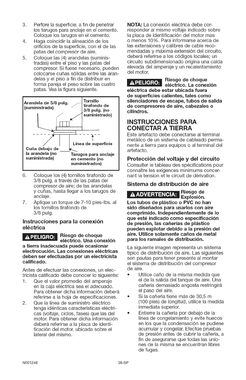
3. Perfore la superficie, a fin de penetrar
los tarugos para anclaje en el cemento.
Coloque los tarugos en el cemento.
4. Haga coincidir la alineaci6n de los
orificios de la superficie, con el de las
patas del compresor de aire.
5. Coloque las (4) arandelas (suminis-
tradas) entre el piso y las patas del
compresor. Si fuese necesario, pueden
colocarse curas s61idas entre las aran-
delas y el piso a fin de distribuir en
forma pareja el peso sobre las cuatro
patas. Vea la figura siguiente.
Arandela de 5/8 pulg ........... Tornillo -
..m,.,.,rod°l .......
I ,............S! s"m"""''°d°l
la arandela (no Tarugos para anclaje
suministrada) en cemento (no
suministrados)
6. Coloque los (4) tornillos tirafondo de
3/8 pulg. a trav6s de las patas del
compresor de aire; de las arandelas
y curas, hasta Ilegar a los tarugos de
anclaje.
7. Aplique un torque de 7-10 pies-lbs, al
los tornillos tirafondo de
3/8 pulg.
Instrucciones para la cone×i6n
el_ctrica
Riesgo de choque
el_ctrico. Una conexibn
atierra inadecuada puede ocasionar
electrocuci6n. Las cone×iones el_ctricas
deben set efectuadas pot un electricista
calificado.
Antes de efectuar las conexiones, un elec-
tricista calificado debe conocer Io siguiente:
1. Que el valor promedio del amperaje
en la caja el6ctrica sea el adecuado.
Para obtener dicha informaci6n deberA
referirse a la hoja de especificaciones.
2. Que la Iinea de suministro el6ctrico
tenga id6nticas caracteristicas el6ctri-
cas (voltaje, ciclos, fases) que las del
motor. Para obtener dicha informaci6n
deberA referirse a la placa de identi-
ficaci6n del motor, ubicada sobre el
lateral del mismo.
NOTA: La conexi6n el6ctrica debe cor-
responder al mismo voltaje indicado sobre
la placa de identificaci6n del motor mas
o menos 10%. Para informarse acerca de
las extensiones y calibres de cable reco-
mendadas y m&xima extensi6n del circuito,
deber& referirse a los c6digos locales; un
circuito subdimensionado origina una caida
elevada del amperaje y un recalentamiento
del motor.
Riesgo de choque
el_ctrico. La conexibn
el_ctrica debe estar ubicada fuera
de superficies calientes, tales como
silenciadores de escape, tubos de salida
de compresores de aire, cabezales o
cilindros.
INSTRUCCIONES PARA
CONECTAR A TIERRA
Este artefacto debe conectarse al terminal
metalico de un sistema de cableado perma-
nente a tierra para equipos o al terminal del
artefacto.
Protecci6n del voltaje y del circuito
Consulter le tableau des sp6cifications pour
connaitre les exigences minimums concer-
nant la tension et le circuit de d6rivation.
Sistema de distribuci6n de aire
Los tubos de pl_stico o PVC no ban
sido diseSados para usarlos con aire
comprimido. Independientemente de Io
que est_ indicado como especificaci6n
de presi6n, las caSerias de pl_stico
pueden e×plotar debido ala presi6n del
aire. Utilice solamente caSos de metal
para los tamales de distribucibn.
La siguiente imagen representa un sistema
tipico de distribuci6n de aire. Las siguientes
son pautas para tener presente al montar
el sistema de distribuci6n del compresor
de aire.
• Utilice carlo de la misma medida que
el de la salida del tanque de aire. Una
careria demasiado angosta restringir&
el paso del aire.
• Si la careria tiene mas de 30,5 m
(100 pies) de Iongitud, utilice la medida
inmediata superior.
• Entierre la careria pot debajo de la
linea de congelamiento y evite huecos
en los que la condensaci6n se pudiese
acumular y congelar. EfectQe pruebas
de presi6n antes de cubrir la careria, a
fin de asegurarse que todas las unio-
nes de la misma se encuentran libres
de fugas.
N001248 38-SP
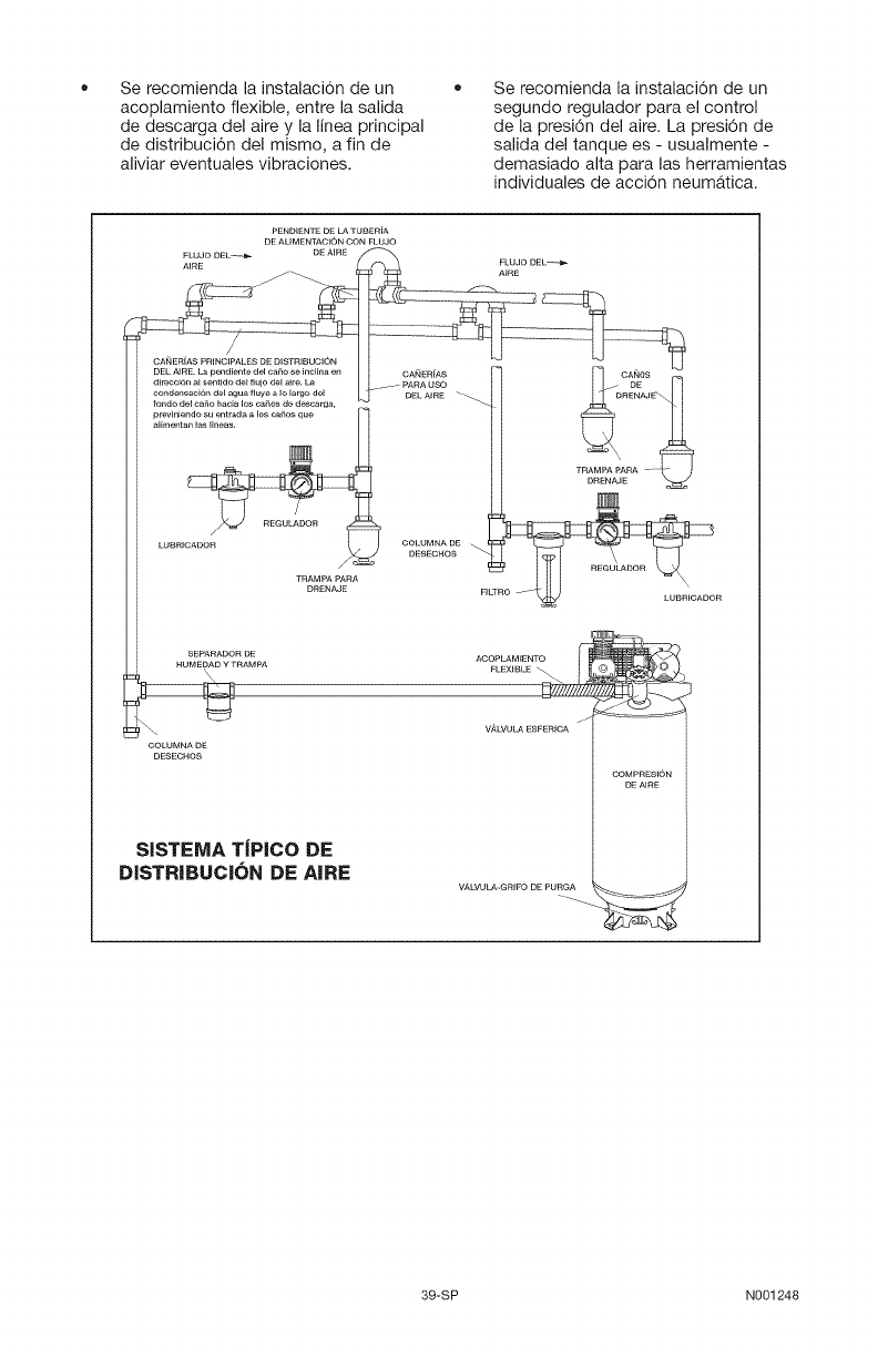
Se recomienda la instalaci6n de un
acoplamiento flexible, entre la salida
de descarga del aire y la linea principal
de distribuci6n del mismo, a fin de
aliviar eventuales vibraciones.
Se recomienda la instalaci6n de un
segundo regulador para el control
de la presi6n del aire. La presi6n de
salida del tanque es - usualmente -
demasiado alta para las herramientas
individuales de acci6n neumAtica.
PENDIENTE DE LA TUBERiA
DE ALIMENTAOION CON FLUJO
FLUJO DEL_-4_ DE AIRE
CANOS
%_g_AJ
TRAMPA PARA .....
LUBRICADOR
SEPARADOR DE ACOPLAMIENTO
HUME_D Y TRAMPA FLEXIBLE
COLUMNA DE DE AIRE
DESECHOS COMPRESK_N
SiSTEMA T|PICO DE
DISTRIBUCION DE AIRE ,,A....................,_
39-SP N001248
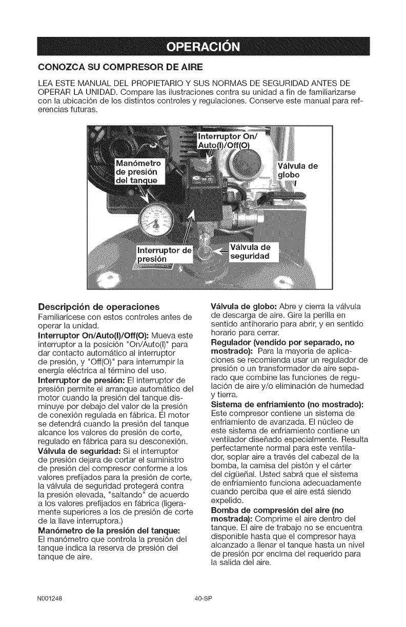
CONOZCA SU COMPRESOR DE AIRE
LEA ESTE MANUAL DEL PROPIETARIO Y SUS NORMAS DE SEGURIDAD ANTES DE
OPERAR LA UNIDAD. Compare las ilustraciones contra su unidad a fin de familiarizarse
con la ubicaci6n de los distintos controles y regulaciones. Conserve este manual para ref-
erencias futuras.
Descripci6n de operaciones
Familiaricese con estos controles antes de
operar la unidad.
Interruptor On/Auto(I}/Off(O}: Mueva este
interruptor a la posici6n "On/Auto(I)" para
dar contacto automatico al interruptor
de presi6n, y "Off(O)" para interrumpir la
energia el6ctrica al t6rmino del uso.
Interruptor de presi6n: El interruptor de
presi6n permite el arranque automAtico del
motor cuando la presi6n del tanque dis-
minuye por debajo del valor de la presi6n
de conexi6n regulada en fabrica. El motor
se detendra cuando la presi6n del tanque
alcance los valores de presi6n de corte,
regulado en fabrica para su desconexi6n.
VAIvula de seguridad: Si el interruptor
de presi6n dejara de cortar el suministro
de presi6n del compresor conforme a los
valores prefijados para la presi6n de corte,
la vAIvula de seguridad protegera contra
la presi6n elevada, "saltando" de acuerdo
a los valores prefijados en fAbrica (ligera-
mente superiores a los de presi6n de corte
de la Ilave interruptora.)
Man6metro de la presi6n del tanque:
El man6metro que controla la presi6n del
tanque indica la reserva de presi6n del
tanque de aire.
Valvula de globo: Abre y cierra la vAIvula
de descarga de aire. Gire la perilla en
sentido antihorario para abrir, yen sentido
horatio para cerrar.
Regulador (vendido pot separado, no
rnostrado}: Para la mayoria de aplica-
ciones se recomienda usar un regulador de
presi6n o un transformador de aire sepa-
rado que combine las funciones de regu-
laci6n de aire y/o eliminaci6n de humedad
y tierra.
Sisterna de enfriarniento (no rnostrado):
Este compresor contiene un sistema de
enfriamiento de avanzada. El nOcleo de
este sistema de enfriamiento contiene un
ventilador dise_ado especialmente. Resulta
perfectamente normal para este ventila-
dot, soplar aire a trav6s del cabezal de la
bomba, la camisa del pist6n y el carter
del cigOe_al. Usted sabra que el sistema
de enfriamiento funciona adecuadamente
cuando perciba que el aire estA siendo
expelido.
Bornba de cornpresi6n del aire (no
rnostrada): Comprime el aire dentro del
tanque. El aire de trabajo no se encuentra
disponible hasta que el compresor haya
alcanzado a Ilenar el tanque hasta un nivel
de presi6n por encima del requerido para
la salida del aire.
N001248 40-SP
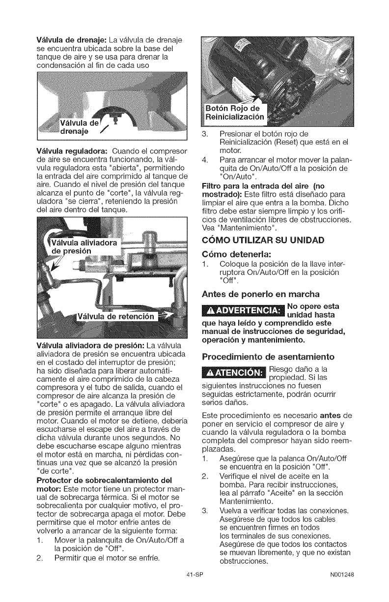
V_lvula de drenaje: La vAIvula de drenaje
se encuentra ubicada sobre la base del
tanque de aire y se usa para drenar la
condensaci6n al fin de cada uso
drenaje
V_lvula reguladora: Cuando el compresor
de aire se encuentra funcionando, la v&l-
vula reguladora esta "abierta", permitiendo
la entrada del aire comprimido al tanque de
aire. Cuando el nivel de presi6n del tanque
alcanza el punto de "corte", la valvula reg-
uladora "se cierra", reteniendo la presi6n
del aire dentro del tanque.
V_lvula de retenci6n
V_lvula aliviadora de presi6n: La v&lvula
aliviadora de presi6n se encuentra ubicada
en el costado del interruptor de presi6n;
ha sido diseSada para liberar autom&ti-
camente el aire comprimido de la cabeza
compresora y el tubo de salida, cuando el
compresor de aire alcanza la presi6n de
"corte" o es apagado. La valvula aliviadora
de presi6n permite el arranque libre del
motor. Cuando el motor se detiene, deberia
escucharse el escape del aire a trav6s de
dicha valvula durante unos segundos. No
debe escucharse escape alguno mientras
el motor esta en march& ni p6rdidas con-
tinuas una vez que se alcanz6 la presi6n
"de corte".
Protector de sobrecalentamiento del
motor: Este motor tiene un protector man-
ual de sobrecarga t6rmica. Si el motor se
sobrecalienta por cualquier motivo, el pro-
tector de sobrecarga apaga el motor. Debe
permitirse que el motor enfrie antes de
volverlo a arrancar de la siguiente forma:
1. Mover la palanquita de On/Auto/Off a
la posici6n de "Off".
2. Permitir que el motor se enfrie.
Bot6n Rojo de
Reinicializaci6n
3. Presionar el bot6n rojo de
Reinicializaci6n (Reset) que est& en el
motor.
4. Para arrancar el motor mover la palan-
quita de On/Auto/Off a la posici6n de
"On/Auto".
Filtro para la entrada del aire (no
mostrado): Este filtro esta diseSado para
limpiar el aire que entra a la bomba. Dicho
filtro debe estar siempre limpio y los orifi-
cios de ventilaci6n libres de obstrucciones.
Vea "Mantenimiento".
COMO UTILIZAR SU UNIDAD
C6mo detenerla:
1. Coloque la posici6n de la Ilave inter-
ruptora On/Auto/Off en la posici6n
"Off".
Antes de ponerlo en marcha
, ,= = , , Noopereesta
unidad hasta
que haya lefdo y comprendido este
manual de instrucciones de seguridad,
operaci6n y mantenimiento.
Procedimiento de asentamiento
Riesgo daSo a la
propiedad. Si las
siguientes instrucciones no fuesen
seguidas estrictamente, podr&n ocurrir
serios daSos.
Este procedimiento es necesario antes de
poner en servicio el compresor de aire y
cuando la valvula reguladora o la bomba
completa del compresor hayan sido reem-
plazadas.
1. AsegOrese que la palanca On!Auto/Off
se encuentra en la posici6n "Off".
2. Verifique el nivel de aceite en la
bomba. Para recibir instrucciones,
lea al parrafo "Aceite" en la secci6n
Mantenimiento.
3. Vuelva a verificar todas las conexiones.
AsegOrese de que todos los cables
se encuentren firmes en todos
los terminales de sus conexiones.
AsegOrese de que todos los contactos
se muevan libremente, y que no existan
obstrucciones.
41-SP N001248
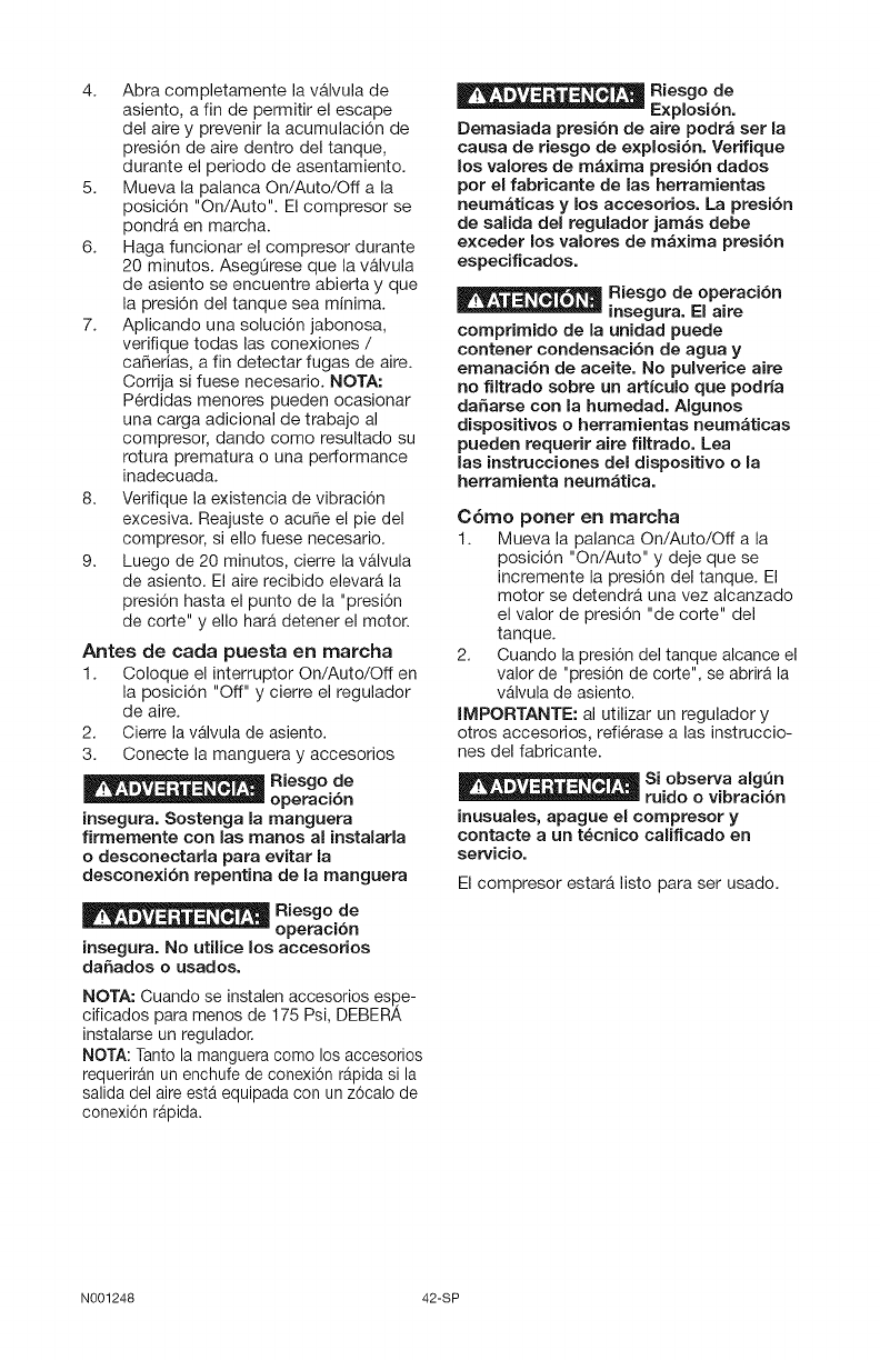
4. Abra completamente la valvula de
asiento, a fin de permitir el escape
del aire y prevenir la acumulaci6n de
presi6n de aire dentro del tanque,
durante el periodo de asentamiento.
5. Mueva la palanca On/Auto/Off a la
posici6n "On/Auto". El compresor se
pondra en marcha.
6. Haga funcionar el compresor durante
20 minutos. AsegQrese que la valvula
de asiento se encuentre abierta y que
la presi6n del tanque sea minima.
7. Aplicando una soluci6n jabonosa,
verifique todas las conexiones /
ca_erias, a fin detectar fugas de aire.
Corrija si fuese necesario. NOTA:
P6rdidas menores pueden ocasionar
una carga adicional de trabajo al
compresor, dando como resultado su
rotura prematura o una performance
inadecuada.
8. Verifique la existencia de vibraci6n
excesiva. Reajuste o acute el pie del
compresor, si ello fuese necesario.
9. Luego de 20 minutos, cierre la v_lvula
de asiento. El aire recibido elevar_ la
presi6n hasta el punto de la "presi6n
de corte" y ello hara.detener el motor.
Antes de carla puesta en marcha
1. Coloque el interruptor On/Auto/Off en
la posici6n "Off" y cierre el regulador
de aire.
2. Cierre la v&lvula de asiento.
3. Conecte la manguera y accesorios
_ Riesgo de
-- operaci6n
insegura. Sostenga la manguera
firrnernente con las rnanos al instalarla
odesconectarla para evitar la
desconexi6n repentina de la rnanguera
_q_-_l_Riesgo de
--ope_ci6n
insegu_. No utilicelos accesorios
daSados ousados.
NOTA: Cuando se instalen accesorios espe-
cificados para menos de 175 Psi, DEBERA
instalarse un regulador.
NOTA: Tanto la manguera come los accesorios
requeriran un enchufe de conexi6n rapida si la
salida del aire esta equipada con un z6calo de
conexi6n rapida.
Riesgo de
-- Explosi6n.
Dernasiada presi6n de aire podr_ set la
causa de riesgo de explosi6n. Verifique
los valores de maxima presi6n dados
pot el fabricante de las herrarnientas
neumaticas y los accesorios. La presi6n
de salida del regulador jarn_s debe
exceder los valores de m_xima presi6n
especificados.
Riesgo de operaci6n
-- insegura. El aire
cornprirnido de la unidad puede
contener condensaci6n de agua y
ernanaci6n de aceite. No pulverice aire
no filtrado sobre un articulo que podria
daSarse con la hurnedad. AIgunos
dispositivos o herramientas neurnaticas
pueden requerir aire filtrado. Lea
las instrucciones del dispositivo ola
herrarnienta neum_tica.
C6mo porter en marcha
1. Mueva la palanca On/Auto/Off a la
posici6n "On/Auto" y deje que se
incremente la presi6n del tanque. El
motor se detendr& una vez alcanzado
el valor de presi6n "de corte" del
tanque.
2. Cuando la presi6n del tanque alcance el
valor de "presi6n de corte", se abrir& la
v_lvula de asiento.
IMPORTANTE: al utilizar un regulador y
otros accesorios, refi6rase alas instruccio-
nes del fabricante.
_Si observa algen
-- ruido o vibraci6n
inusuales, apague el cornpresor y
contacte a un t_cnico calificado en
servicio.
El compresor estar& listo para ser usado.
N001248 42-SP
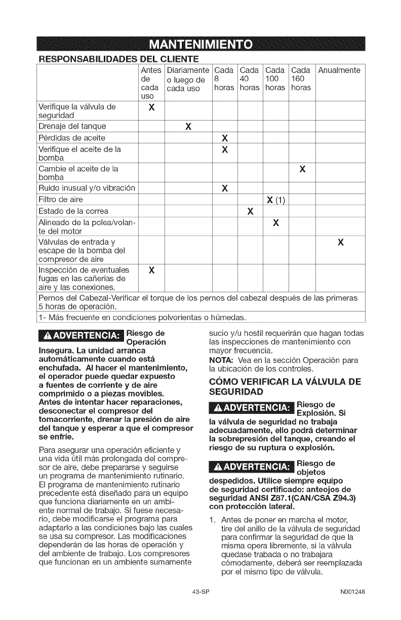
RESPONSABILIDADES DEL CLIENTE
Antes Diariamente Cada Cada Cada Cada Anualmente
de o luego de 8 40 100 160
cada cada uso horas horas horas horas
USO
XVerifique la vAIvula de
seguridad
Drenaje del tanque
P6rdidas de aceite
Verifique el aceite de la
bomba
Cambie el aceite de la
bomba
Ruido inusual y/o vibraci6n
Filtro de aire
Estado de la correa
Alineado de la polea/volan-
te del motor
V&lvulas de entrada y
escape de la bomba del
compresor de aire
Inspecci6n de eventuales
fugas en las ca_erias de
aire y las conexiones.
X
X
X
X
X
X (1)
X
X
X
X
Pernos del CabezaI-Verificar el torque de los pernos del cabezal despues de las primeras
5 horas de operaci6n.
1- MAs frecuente en condiciones polvorientas o hOmedas.
Riesgo de
-- Operaci6n
Insegura. La unidad arranca
automaticamente cuando esta
enchufada. AI hacer el mantenirniento,
el operador puede quedar expuesto
afuentes de corriente y de abe
comprirnido o a piezas movibles.
Antes de intentar hacer reparaciones,
desconectar el cornpresor del
tornacorriente, drenar la presi6n de aire
del tanque y esperar aque el compresor
se enfrie.
Para asegurar una operaci6n eficiente y
una vida Otil m&s prolongada del compre-
sor de aire, debe prepararse y seguirse
un programa de mantenimiento rutinario.
El programa de mantenimiento rutinario
precedente estA dise_ado para un equipo
que funciona diariamente en un ambi-
ente normal de trabajo. Si fuese necesa-
rio, debe modificarse el programa para
adaptarlo alas condiciones bajo las cuales
se usa su compresor. Las modificaciones
depender&n de las horas de operaci6n y
del ambiente de trabajo. Los compresores
que funcionan en un ambiente sumamente
sucio y/u hostil requerir&n que hagan todas
las inspecciones de mantenimiento con
mayor frecuencia.
NOTA: Vea en la secci6n Operaci6n para
la ubicaci6n de los controles.
COMO VERIFICAR LA VALVULA DE
SEGURIDAD
la valvula de seguridad no trabaja
adecuadamente, ello podr_ deterrninar
la sobrepresi6n del tanque, creando el
riesgo de su ruptura oexplosi6n.
_ Riesgo de
objetos
despedidos. Utilice siernpre equipo
de seguridad certificado: anteojos de
seguridad ANSi Z87.1(CAN/CSA Z94.3)
con protecci6n lateral.
1. Antes de poner en marcha el motor,
tire del anillo de la valvula de seguridad
para confirmar la seguridad de que la
misma opera libremente, si la v&lvula
quedase trabada o no trabajara
c6modamente, debera ser reemplazada
por el mismo tipo de vAIvula.
43-SP N001248
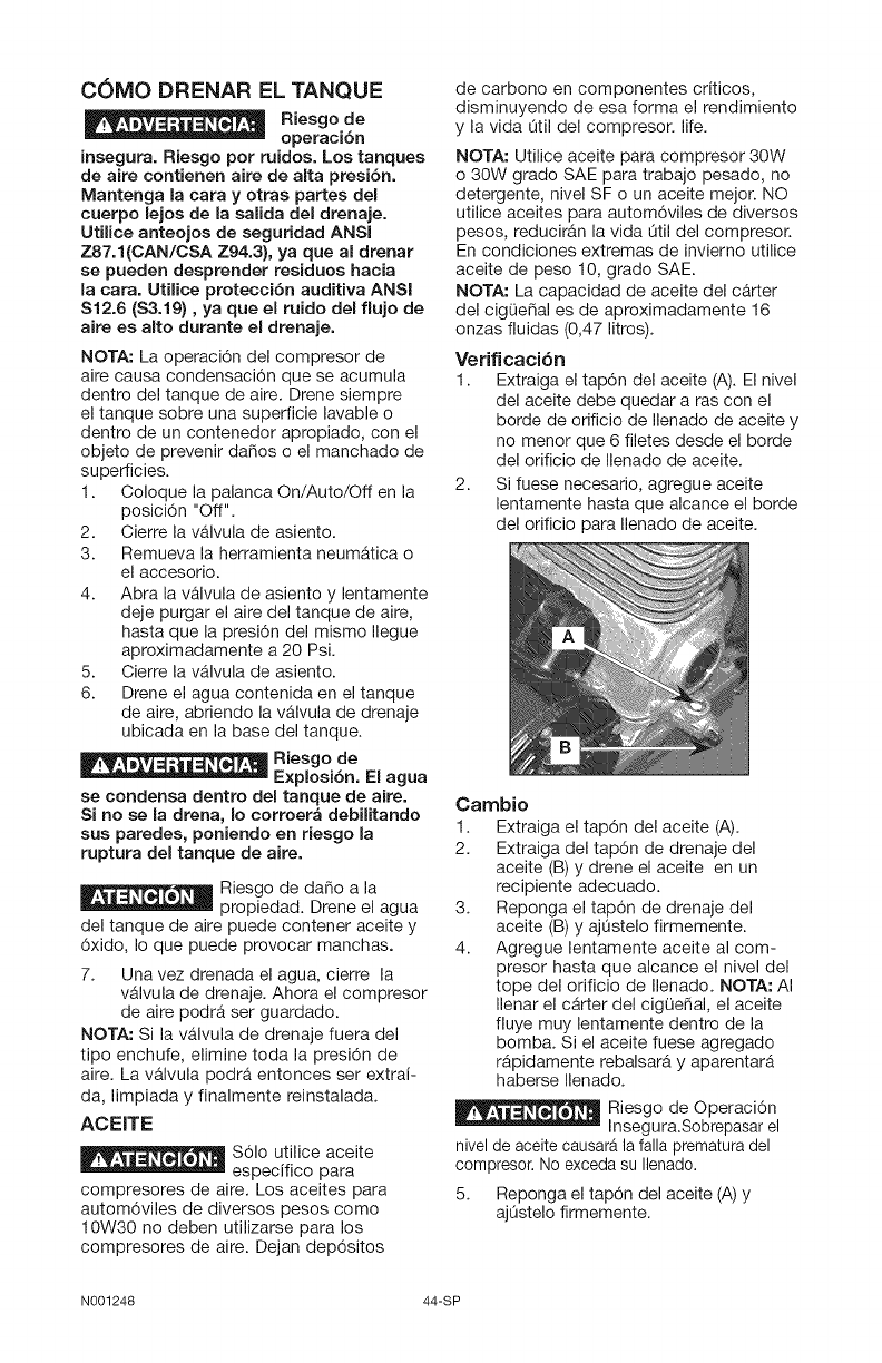
C0MO DRENAR EL TANQUE
Riesgo de
operaci6n
insegura. Riesgo pot ruidos. Los tanques
de aire contienen aire de aita presi6n.
Mantenga la cara y otras partes del
cuerpo lejos de la salida del drenaje.
Utilice anteojos de seguridad ANSI
Z87.1 {CAN/CSA Z94.3}, ya que al drenar
se pueden desprender residues hacia
la cara. Utilice protecci6n auditiva ANSI
S12.6 (S3.19}, ya que el ruido del flujo de
aire es alto durante el drenaje.
NOTA: La operacidn del compresor de
aire causa condensacidn que se acumula
dentro del tanque de aire. Drene siempre
el tanque sobre una superficie lavable o
dentro de un contenedor apropiado, con el
objeto de prevenir daSos o el manchado de
superficies.
1. Coloque la palanca On/Auto/Off en la
posicidn "Off".
2. Cierre la v&lvula de asiento.
3. Remueva la herramienta neumAtica o
el accesorio.
4. Abra la valvula de asiento y lentamente
deje purgar el aire del tanque de aire,
hasta que la presidn del mismo Ilegue
aproximadamente a 20 Psi.
5. Cierre la vAIvula de asiento.
6. Drene el agua contenida en el tanque
de aire, abriendo la valvula de drenaje
ubicada en la base del tanque.
Riesgo de
Explosi6n. El agua
se condensa dentro del tanque de aire.
Si no se la drena, Io corroera debilitando
sus paredes, poniendo en riesgo la
ruptura del tanque de aire.
Riesgo de daSo a la
propiedad. Drene el agua
del tanque de aire puede contener aceite y
6xido, Io que puede provocar manchas.
7. Una vez drenada el agua, cierre la
valvula de drenaje. Ahora el compresor
de aire podrA ser guardado.
NOTA: Si la valvula de drenaje fuera del
tipo enchufe, elimine toda la presi6n de
aire. La valvula podra entonces ser extrai-
da, limpiada y finalmente reinstalada.
ACEITE
$61o utilice aceite
especifico para
compresores de aire. Los aceites para
autom6viles de diversos pesos como
10W30 no deben utilizarse para los
compresores de aire. Dejan dep6sitos
de carbono en componentes criticos,
disminuyendo de esa forma el rendimiento
y la vida Qtil del compresor, life.
NOTA: Utilice aceite para compresor 30W
o 30W grado SAE para trabajo pesado, no
detergente, nivel SF o un aceite mejor. NO
utilice aceites para autom6viles de diversos
pesos, reduciran la vida Qtil del compresor.
En condiciones extremas de invierno utilice
aceite de peso 10, grado SAE.
NOTA: La capacidad de aceite del carter
del cigOeSal es de aproximadamente 16
onzas fluidas (0,47 litros).
Verificaci6n
1. Extraiga el tap6n del aceite (A). El nivel
del aceite debe quedar a ras con el
borde de orificio de Ilenado de aceite y
no menor que 6 filetes desde el borde
del orificio de Ilenado de aceite.
2. Si fuese necesario, agregue aceite
lentamente hasta que alcance el borde
del orificio para Ilenado de aceite.
Cambio
1. Extraiga el tap6n del aceite (A).
2. Extraiga del tap6n de drenaje del
aceite (B) y drene el aceite en un
recipiente adecuado.
3. Reponga el tap6n de drenaje del
aceite (B) y ajestelo firmemente.
4. Agregue lentamente aceite al com-
presor hasta que alcance el nivel del
tope del orificio de Ilenado. NOTA: AI
Ilenar el carter del cigQeSal, el aceite
fluye muy lentamente dentro de la
bomba. Si el aceite fuese agregado
rApidamente rebalsarA y aparentarA
haberse Ilenado.
Riesgo de Operaci6n
Insegura.Sobrepasar el
nivel de aceite causara la falla prematura del
compresor. No exceda su Ilenado.
5. Reponga el tap6n del aceite (A) y
ajOstelo firmemente.
N001248 44-SP
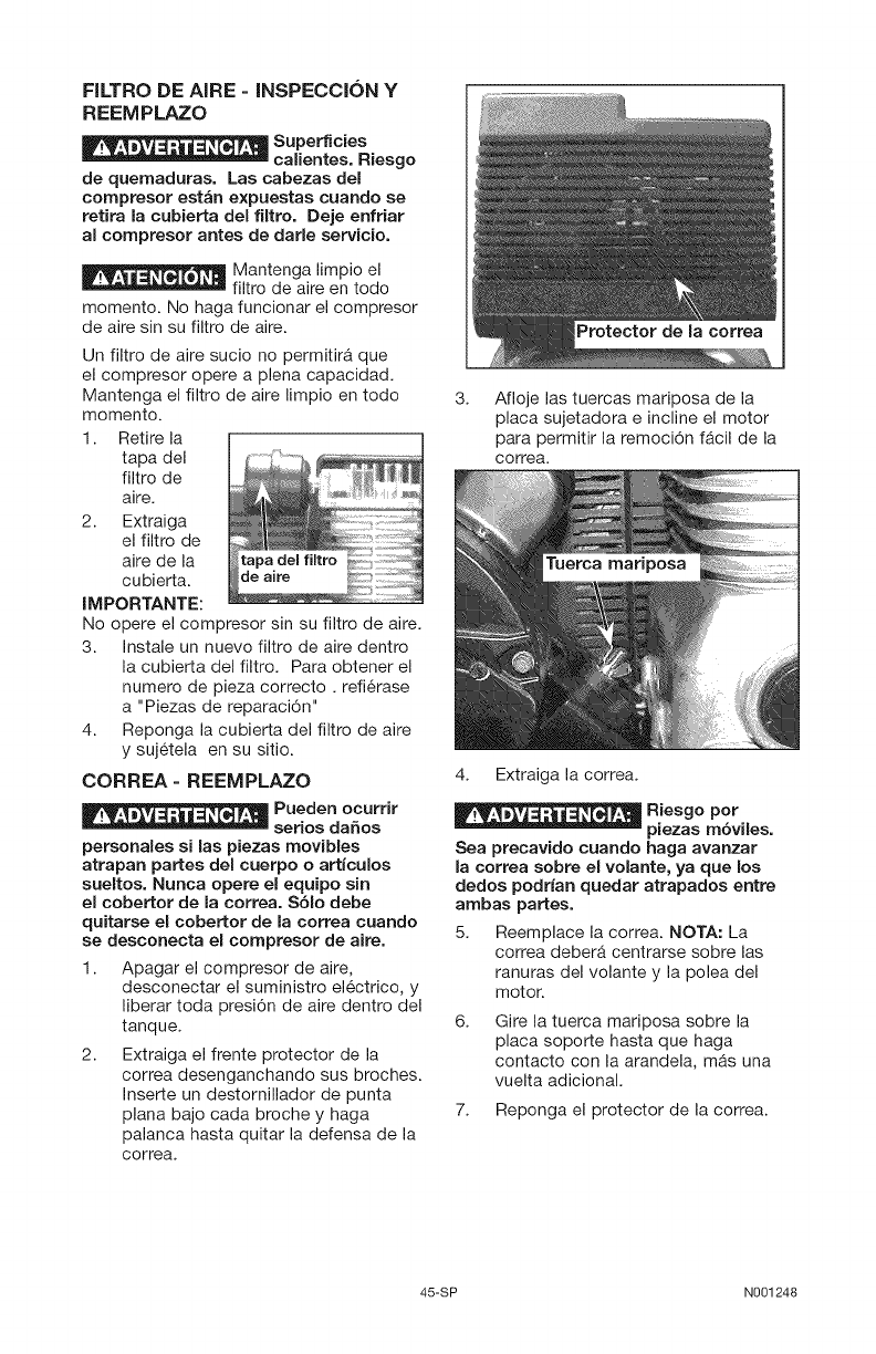
FILTRO DE AIRE - INSPECCION Y
REEMPLAZO
Superficies
calientes. Riesgo
de quemaduras. Las cabezas del
compresor estan expuestas cuando se
retira la cubierta del flltro. Deje enfriar
al compresor antes de darle servicio.
Mantenga limpio el
filtro de aire en todo
momento. No haga funcionar el compresor
de aire sin su filtro de aire.
Un filtro de aire sucio no permitira que
el compresor opere a plena capacidad.
Mantenga el filtro de aire limpio en todo
momento.
1. Retire la
tapa del
filtro de
aire.
2. Extraiga
el filtro de
aire de la
cubierta.
IMPORTANTE:
No opere el compresor sin su filtro de aire.
3. Instale un nuevo filtro de aire dentro
la cubierta del filtro. Para obtener el
numero de pieza correcto, refi6rase
a "Piezas de reparaci6n"
4. Reponga la cubierta del filtro de aire
y suj6tela en su sitio.
CORREA- REEMPLAZO
Pueden ocurrir
serios daSos
personales si las piezas movibles
atrapan partes del cuerpo o articulos
sueltos. Nunca opere el equipo sin
el cobertor de la correa. Sblo debe
quitarse el cobertor de la correa cuando
se desconecta el compresor de aire.
1. Apagar el compresor de aire,
desconectar el suministro el6ctrico, y
liberar toda presi6n de aire dentro del
tanque.
2. Extraiga el frente protector de la
correa desenganchando sus broches.
Inserte un destornillador de punta
plana bajo cada broche y haga
palanca hasta quitar la defensa de la
correa.
3. Afloje las tuercas mariposa de la
placa sujetadora e incline el motor
para permitir la remoci6n f&cil de la
correa.
4. Extraiga la correa.
Riesgo pot
piezas mbviles.
Sea precavido cuando haga avanzar
la correa sobre el volante, ya que los
dedos podrian quedar atrapados entre
ambas partes.
5. Reemplace la correa. NOTA: La
correa deber& centrarse sobre las
ranuras del volante y la polea del
motor.
6. Gire la tuerca mariposa sobre la
placa soporte hasta que haga
contacto con la arandela, m&s una
vuelta adicional.
7. Reponga el protector de la correa.
45-SP N001248
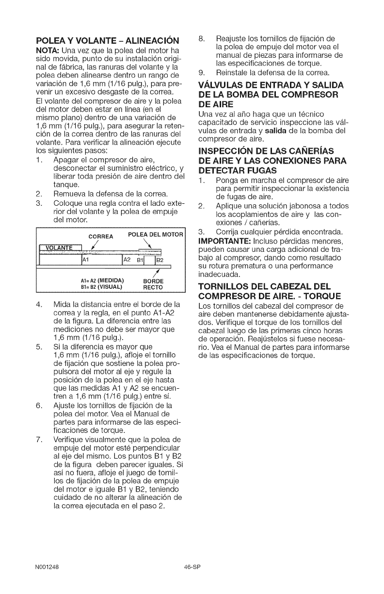
POLEA YVOLANTE - ALINEACION
NOTA: Una vez que la polea del motor ha
sido movida, punto de su instalaci6n origi-
nal de fabrica, las ranuras del volante y la
polea deben alinearse dentro un rango de
variaci6n de 1,6 mm (1/16 pulg.), para pre-
venir un excesivo desgaste de la correa.
El volante del compresor de aire y la polea
del motor deben estar en linea (en el
mismo piano) dentro de una variaci6n de
1,6 mm (1/16 pulg.), para asegurar la reten-
ci6n de la correa dentro de las ranuras del
volante. Para verificar la alineaci6n ejecute
los siguientes pasos:
1. Apagar el compresor de aire,
desconectar el suministro el6ctrico, y
liberar toda presi6n de aire dentro del
tanque.
2. Remueva la defensa de la correa.
3. Coloque una regla contra el lado exte-
rior del volante y la polea de empuje
del motor.
CORREA POLEA DEL MOTOR
1 I 81/I
/
AI= A2 (MEDIDA) BORDE
BI= B2 (VISUAL) RECTO
4. Mida la distancia entre el borde de la
correa y la regla, en el punto A1-A2
de la figura. La diferencia entre las
mediciones no debe ser mayor que
1,6 mm (1/16 pulg.).
5. Si la diferencia es mayor que
1,6 mm (1/16 pulg.), afloje el tornillo
de fijaci6n que sostiene la polea pro-
pulsora del motor al eje y regule la
posici6n de la polea en el eje hasta
que las medidas A1 y A2 se encuen-
tren a 1,6 mm (1/16 pulg.) entre si.
6. Ajuste los tornillos de fijaci6n de la
polea del motor. Vea el Manual de
partes para informarse de las especi-
ficaciones de torque.
7. Verifique visualmente que la polea de
empuje del motor est6 perpendicular
al eje del mismo. Los puntos B1 y B2
de la figura deben parecer iguales. Si
asi no fuera, afloje el juego de tornil-
los de fijaci6n de la polea de empuje
del motor e iguale B1 y B2, teniendo
cuidado de no alterar la alineaci6n de
la correa ejecutada en el paso 2.
8. Reajuste los tornillos de fijaci6n de
la polea de empuje del motor vea el
manual de piezas para informarse de
las especificaciones de torque.
9. Reinstale la defensa de la correa.
VALVULAS DE ENTRADA Y SAUDA
DE LA BOMBA DEL COMPRESOR
DE AIRE
Una vez al a6o haga que un t6cnico
capacitado de servicio inspeccione las val-
vulas de entrada y salida de la bomba del
compresor de aire.
INSPECCION DE LAS CANERJAS
DE AIRE Y LAS CONEXlONES PARA
DETECTAR FUGAS
1. Ponga en marcha el compresor de aire
para permitir inspeccionar la existencia
de fugas de aire.
2. Aplique una soluci6n jabonosa a todos
los acoplamientos de aire y las con-
exiones /caSerias.
3. Corrija cualquier p@dida encontrada.
IMPORTANTE: Incluso p@didas menores,
pueden causar una carga adicional de tra-
bajo al compresor, dando como resultado
su rotura prematura o una performance
inadecuada.
TORNILLOS DEL CABEZAL DEL
COMPRESOR DE AIRE. - TORQUE
Los tornillos del cabezal del compresor de
aire deben mantenerse debidamente ajusta-
dos. Verifique el torque de los tornillos del
cabezal luego de las primeras cinco horas
de operaci6n. ReajOstelos si fuese necesa-
rio. Vea el Manual de partes para informarse
de las especificaciones de torque.
N001248 46-SP
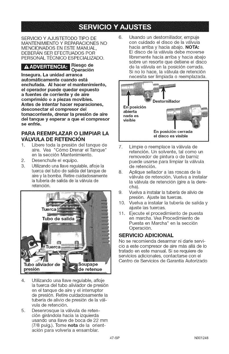
SERVICIO Y AJUSTETODO TIPO DE
MANTENIMIENTO Y REPARACIONES NO
MENCIONADOS EN ESTE MANUAL,
DEBERAN SER EFECTUADOS POR
PERSONAL TECNICO ESPECIALIZADO.
Riesgo de
Operacibn
Insegura. La unidad arranca
automaticamente cuando esta
enchufada. AI hacer el mantenimiento,
el operador puede quedar e×puesto
afuentes de corriente y de aire
comprimido o a piezas movibles.
Antes de intentar hacer reparaciones,
desconectar el compresor del
tornacorriente, drenar la presi6n de aire
del tanque y esperar aque el compresor
se enfrie.
PARA REEMPLAZAR OLIMPIAR LA
VALVULA DE RETENCION
1. Libere toda la presi6n del tanque de
aire. Vea "C6mo Drenar el Tanque"
en la secci6n Mantenimiento.
2. Desenchufe el equipo.
3. Utilizando una Ilave regulable, afloje la
tuerca del tubo de salida del tanque de
aire y la bomba. Retire cuidadosamente
la tuberfa de salida de la valvula de
retenci6n.
TILlerca
Tubo de salida
de retenue
6. Usando un destornillador, empuje
con cuidado el disco de la valvula
hacia arriba y hacia abajo. NOTA:
El disco de la valvula debe moverse
libremente hacia arriba y hacia abajo
sobre un resorte que detiene el disco
de la vAIvula en la posici6n cerrada.
Si no Io hace, la valvula de retenci6n
necesita ser limpiada o reemplazada.
Oestornillador
En posici6n
abierta
nada es
visible
En posici6n cerrada
el disco es visible
7. Limpie o reemplace la valvula de
retenci6n. Un solvente, tal como un
removedor de pintura o de barniz
puede usarse para limpiar la vAIvula
de retenci6n.
8. Aplique sellador alas roscas de la
valvula de retenci6n. Vuelva a instalar
la vAIvula de retenci6n (gire a la dere-
cha).
9. Vuelva a instalar la tuberfa de alivio de
presi6n. Ajuste las tuercas.
10. Vuelva a instalar la tuberia de salida y
ajuste las tuercas.
11. Ejecute el procedimiento de puesta
en marcha. Vea Procedimiento de
Puesta en Marcha" en la secci6n
Operaci6n.
SERVIClO ADICIONAL
No se recomienda desarmar ni darle servi-
cio a este compresor de aire mas alia de Io
tratado en este manual. Si se requiere de
servicios adicionales, contactarse con el
Centro de Servicios de Garantia Autorizado
4. Utilizando una Ilave regulable, afloje
la tuerca del tubo aliviador de presi6n
en el tanque de aire y el interruptor
de presi6n. Retire cuidadosamente la
tuberia de alivio de presi6n de la vAI-
vula de retenci6n.
5. Desenrosque la valvula de reten-
ci6n girandola hacia la izquierda
usando una Ilave de boca de 22 mm
(7/8 pulg.). Tome nota de la orient-
aci6n para volverla a ensamblar.
47-SP N001248
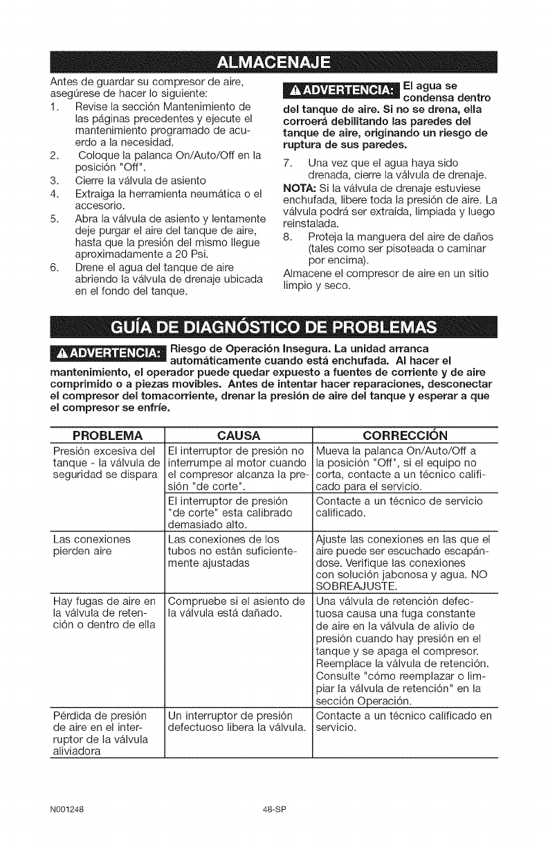
Antes de guardar su compresor de aire,
aseglOrese de hacer Io siguiente:
1. Revise la secci6n Mantenimiento de
las paginas precedentes y ejecute el
mantenimiento programado de acu-
erdo a la necesidad.
2. Coloque la palanca On/Auto/Off en la
posici6n "Off".
3. Cierre la vAlvula de asiento
4. Extraiga la herramienta neumAtica o el
accesorio.
5. Abra la valvula de asiento y lentamente
deje purgar el aire del tanque de aire,
hasta que la presi6n del mismo Ilegue
aproximadamente a 20 Psi.
6. Drene el agua del tanque de aire
abriendo la valvula de drenaje ubicada
en el fondo del tanque.
_EI agua se
condensa dentro
del tanque de aire. Si no se drena, ella
corroera debilitando las paredes del
tanque de aire, originando un riesgo de
ruptura de sus paredes.
7. Una vez que el agua haya sido
drenada, cierre la valvula de drenaje.
NOTA: Si la vAIvula de drenaje estuviese
enchufada, libere toda la presi6n de aire. La
valvula podrA ser extraida, limpiada y luego
reinstalada.
8. Proteja la manguera del aire de da_os
(tales como ser pisoteada o caminar
por encima).
Almacene el compresor de aire en un sitio
limpio y seco.
w,= _- , , Riesgo de Operaci6n Insegura. La unidad arranca
automaticarnente cuando esta enchufada. AI hacer el
mantenimiento, el operador puede quedar expuesto a fuentes de corriente y de aire
comprirnido o a piezas rnovibles. Antes de intentar hacer reparaciones, desconectar
el compresor del tornacorriente, drenar la presibn de aire del tanque y esperar aque
el compresor se enfrie.
PROBLEMA
Presi6n excesiva del
tanque - la v&lvula de
seguridad se dispara
CAUSA
El interruptor de presi6n no
interrumpe al motor cuando
el compresor alcanza la pre-
si6n "de corte".
El interruptor de presi6n
"de corte" esta calibrado
demasiado alto.
Las conexiones de los
tubes no estan suficiente-
mente ajustadas
Las conexiones
pierden aire
Hay fugas de aire en
la valvula de reten-
ci6n o dentro de ella
P6rdida de presi6n
de aire en el inter-
ruptor de la valvula
aliviadora
Compruebe si el asiento de
la v&lvula est& dafiado.
Un interrupter de presi6n
defectuoso libera la vAIvula.
CORRECCION
Mueva la palanca On/Auto/Off a
la posici6n "Off", si el equipo no
corta, contacte a un t6cnico califi-
cado para el servicio.
Contacte a un t6cnico de servicio
calificado.
Ajuste las conexiones en las que el
aire puede ser escuchado escap&n-
dose. Verifique las conexiones
con soluci6n jabonosa y agua. NO
SOBREAJUSTE.
Una valvula de retenci6n defec-
tuosa causa una fuga constante
de aire en la v&lvula de alivio de
presi6n cuando hay presi6n en el
tanque y se apaga el compresor.
Reemplace la valvula de retenci6n.
Consulte "c6mo reemplazar o lim-
piar la v&lvula de retenci6n" en la
secci6n Operaci6n.
Contacte a un t6cnico calificado en
servicio.
N001248 48-SP
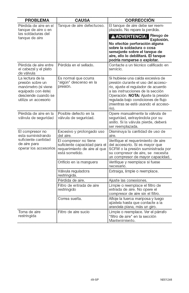
PROBLEMA
P6rdida de aire en el
tanque de aire o en
las soldaduras del
tanque de aire
P6rdida de aire entre
el cabezal y el plato
de v&lvula
La lectura de la
presi6n sobre un
man6metro (si viene
equipado con este)
desciende cuando se
utiliza un accesorio
P6rdida de aire en la
v&lvula de seguridad
El compresor no
esta suministrando
suficiente cantidad
de aire para
operar los accesorios
CAUSA
Tanque de aire defectuoso.
P6rdida en el sellado.
Es normal que ocurra
"algOn" descenso en la
_resi6n.
Posible defecto en la
v&lvula de seguridad.
Excesivo y prolongado uso
del aire.
El compresor no tiene
suficiente capacidad para el
requerimiento de aire al que
lest& sometido.
Orificio en la manguera
V&lvula reguladora
restringida.
P6rdida de aire.
Filtro de entrada de aire
restringido
Correa suelta.
Toma de aire Filtro de aire sucio
restringida
CORRECCION
El tanque de aire debe ser reem-
plazado. No repare la perdida.
No efectue perforaci6n alguna
sobre la soldadura o cosa
sernejante sobre el tanque de
aire, ello Io debilitate. El tanque
podria romperse o explotar.
Contacte a un t6cnico calificado en
servicio.
Si hubiese una caida excesiva de
presi6n durante el uso del acceso-
rio, ajuste el regulador de acuerdo
alas instrucciones de la secci6n
Operaci6n. NOTA: Ajuste la presi6n
regulada bajo condiciones de flujo
(mientras se est6 usando el acceso-
rio).
Opere manualmente la v&lvula de
seguridad, extray6ndola pot su
anillo. Si la v&lvula pierde, deber&
ser reemplazada.
Disminuya la cantidad de uso de
aire.
Verifique el requerimiento de aire
del accesorio. Si es mayor que
SCFM o la presi6n suministrada por
su compresor de aire, se necesita
un compresor de mayor capacidad.
Verifique y reemplace si fuese
necesario.
Extraiga, limpie o reemplace.
Ajuste las conexiones.
Limpie o reemplace el filtro de
entrada de aire. No opere el
compresor de aire sin el filtro.
Afloje la tuerca mariposa y luego
ajQstela hasta que contacte a la
arandela plana, m&s un giro.
Limpie o reemplace. Ver el p&rrafo
"filtro de aire" en la secci6n
Mantenimiento.
49-SP N001248
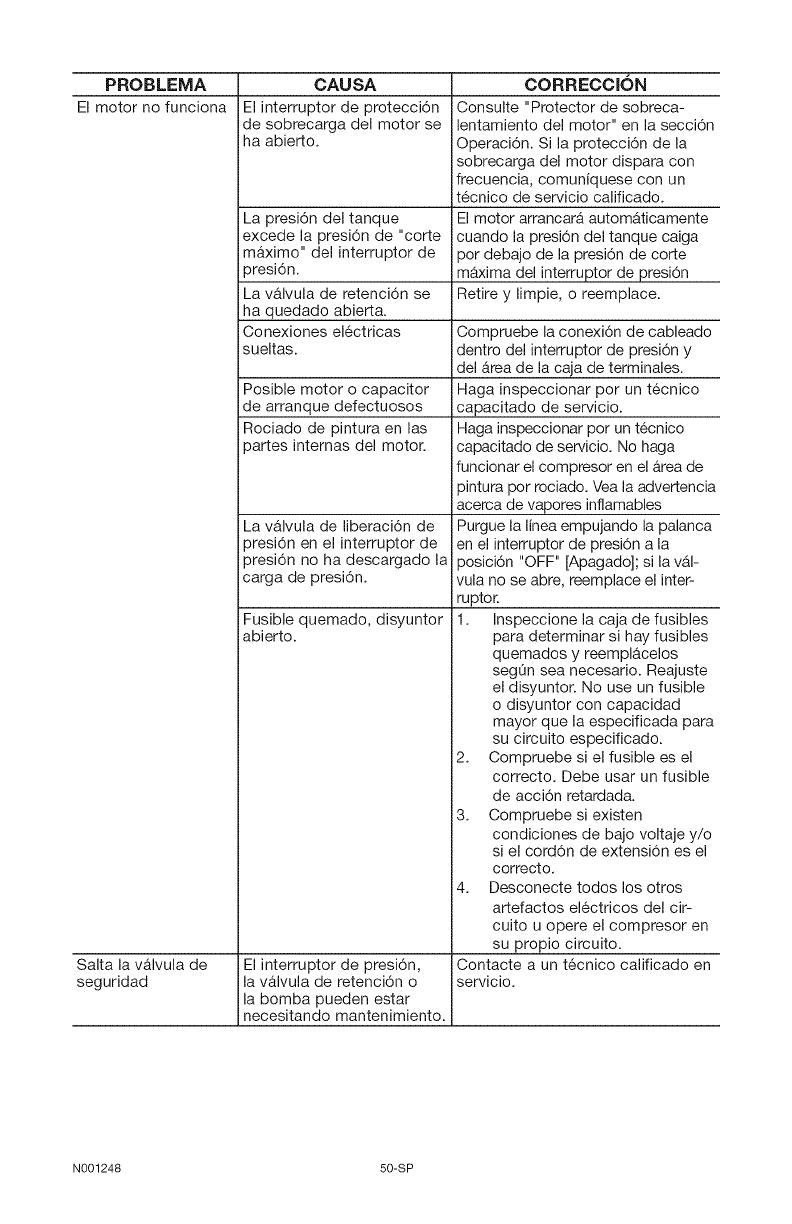
PROBLEMA
El motor no funciona
CAUSA
El interruptor de protecci6n
ide sobrecarga del motor se
iha abierto.
Salta la valvula de
seguridad
La presi6n del tanque
excede la presi6n de "corte
maximo" del interruptor de
)resi6n.
La valvula de retenci6n se
ha quedado abierta.
Conexiones el6ctricas
sueltas.
Posible motor o capacitor
de arranque defectuosos
Rociado de pintura en las
)artes intemas del motor.
La valvula de liberaci6n de
)resi6n en el interruptor de
)resi6n no ha descargado la
;arga de presi6n.
Fusible quemado, disyuntor
abierto.
El interruptor de presi6n,
la valvula de retenci6n o
la bomba pueden estar
inecesitando mantenimiento.
CORRECClON
Consulte "Protector de sobreca-
lentamiento del motor" en la secci6n
Operaci6n. Si la protecci6n de la
sobrecarga del motor dispara con
frecuencia, comuniquese con un
t6cnico de servicio calificado.
El motor arrancara automaticamente
cuando la presi6n del tanque caiga
por debajo de la presi6n de corte
maxima del interruptor de presi6n
Retire y limpie, o reemplace.
Compruebe la conexi6n de cableado
dentro del interruptor de presi6n y
del Area de la caja de terminales.
Haga inspeccionar pot un t6cnico
capacitado de servicio.
Haga inspeccionar pot un t6cnico
capacitado de servicio. No haga
funcionar el compresor en el Area de
pintura por rociado. Vea la advertencia
acerca de vapores inflamables
Purgue la linea empujando la palanca
en el interruptor de presi6n a la
posici6n "OFF" [Apagado]; si la val-
vula no se abre, reemplace el inter-
ruptor.
1. Inspeccione la caja de fusibles
para determinar si hay fusibles
quemados y reemplacelos
segOn sea necesario. Reajuste
el disyuntor. No use un fusible
o disyuntor con capacidad
mayor que la especificada para
su circuito especificado.
2. Compruebe si el fusible es el
correcto. Debe usar un fusible
de acci6n retardada.
3. Compruebe si existen
condiciones de bajo voltaje y/o
si el cord6n de extensi6n es el
correcto.
4. Desconecte todos los otros
artefactos electricos del cir-
cuito u opere el compresor en
su propio circuito.
Contacte a un t6cnico calificado en
servicio.
N001248 50-SP
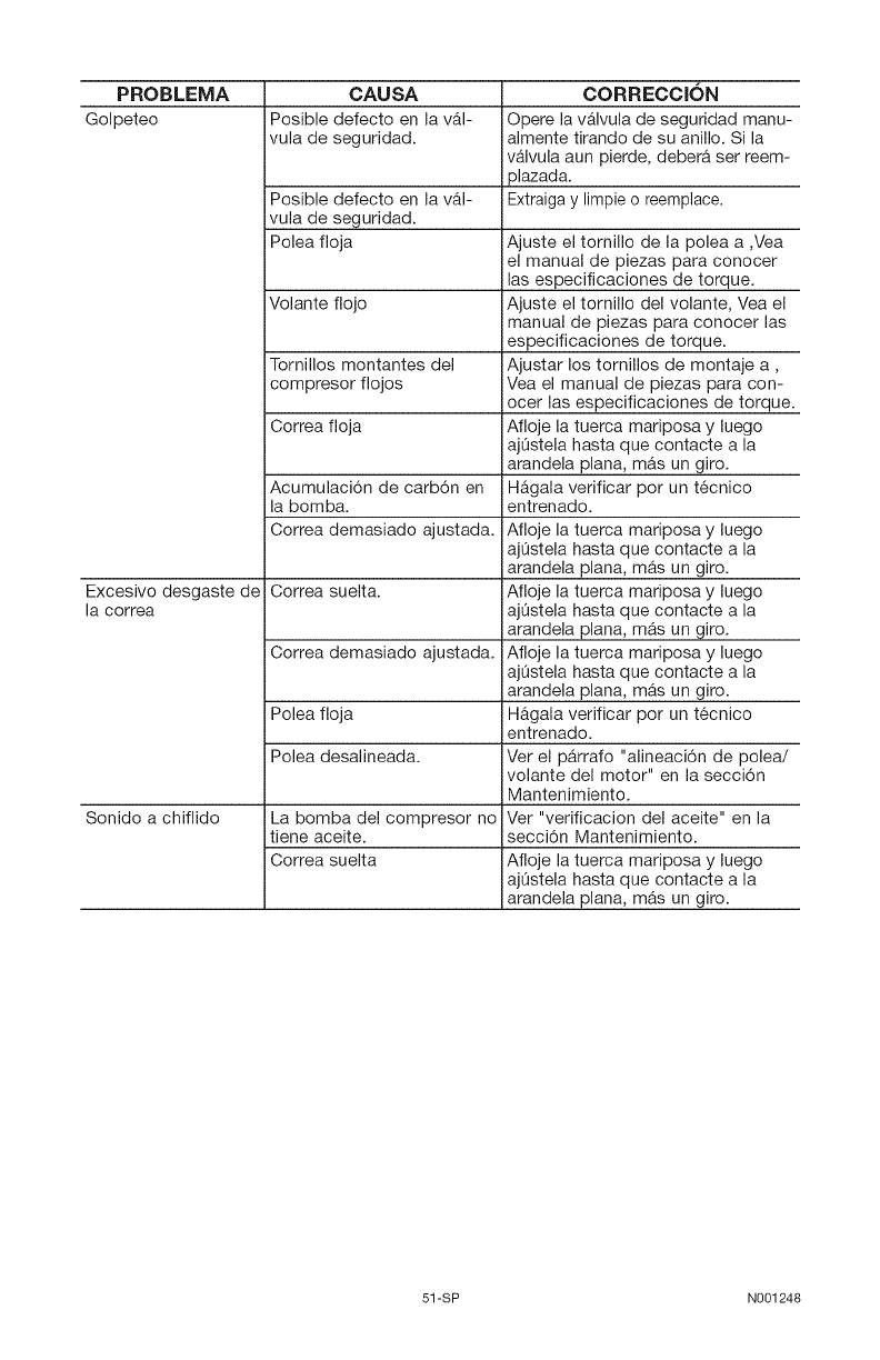
PROBLEMA
Golpeteo
CAUSA
Posible defecto en la v&l-
vula de seguridad.
Posible defecto en la val-
vula de seguridad.
Polea floja
Volante flojo
Tornillos montantes del
icompresor flojoa
Correa floja
Acumulaci6n de carb6n en
la bomba.
Correa demasiado ajustada.
CORRECClON
Opere la v&lvula de seguridad manu-
almente tirando de su anillo. Si la
valvula aun pierde, debera ser reem-
plazada.
Extraiga y limpie o reemplace.
Ajuste el tornillo de la polea a ,Vea
el manual de piezas para conocer
las especificaciones de torque.
Ajuste el tornillo del volante, Vea el
manual de piezas para conocer las
especificaciones de torque.
Ajustar los tornillos de montaje a,
Vea el manual de piezas para con-
ocer las especificaciones de torque.
Afloje la tuerca mariposa y luego
ajQstela hasta que contacte a la
arandela plana, m_s un giro.
Hagala verificar pot un t6cnico
entrenado.
Afloje la tuerca mariposa y luego
ajQstela hasta que contacte a la
arandela plana, mas un giro.
Excesivo desgaste de Correa suelta. Afloje la tuerca mariposa y luego
la correa ajQstela hasta que contacte a la
arandela plana, m&s un giro.
Correa demasiado ajustada. Afloje la tuerca mariposa y luego
Polea floja
Polea desalineada.
La bomba del compresor no
tiene aceite.
Correa suelta
Sonido a chiflido
ajQstela hasta que contacte a la
arandela plana, mas un giro.
Hagala verificar pot un t6cnico
entrenado.
Ver el parrafo "alineaci6n de polea/
volante del motor" en la secci6n
Mantenimiento.
Ver "verificacion del aceite" en la
secci6n Mantenimiento.
Afloje la tuerca mariposa y luego
ajQstela hasta que contacte a la
arandela plana, m_s un giro.
51-SP N001248

N001248 52

53 N001248

N001248 54
Repair Protection Agreements
Congratulations on making a smart pur-
chase. Your new Craftsman @ product
is designed and manufactured for years
of dependable operation. But like all
products, it may require repair from time
to time. That's when having a Repair
Protection Agreement can save you
money and aggravation.
Purchase a Repair Protection Agreement
now and protect yourself from unexpected
hassle and expense.
Here's what's included in the Agreement:
[] Expert service by our 12,000
professional repair specialists
[] Unlimited service and no charge for
parts and labor on all covered repairs
[] Product replacement if your covered
product can't be fixed
[] Discount of 10% from regular price
of service and service-related parts
not covered by the agreement; also,
10% off regular price of preventive
maintenance check
[] Fast help by phone - phone support
from a Sears technician on products
requiring in-home repair, plus
convenient repair scheduling
Once you purchase the Agreement, a
simple phone call is all that it takes for you
to schedule service. You can call anytime
day or night, or schedule a service appoint-
ment online.
Sears has over 12,000 professional repair
specialists, who have access to over 4.5
million quality parts and accessories. That's
the kind of professionalism you can count
on to help prolong the life of your new
purchase for years to come. Purchase your
Repair Protection Agreement today!
Some limitations and exclusions apply.
For prices and additional information
call 1=800=827=6655.
Sears Installation Service
For Sears professional installation of home
appliances, garage door openers, water
heaters, and other major home item,_ in
the U.S.A. call 1=800=4=MY=HOME W2
Contratos de Protecci6n para
Reparaciones
Feficitaciones por hacer una compra
inteligente. Su nueva unidad Craftsman @
esta diseSada y fabricada para aSos de
operacidn confiable; pero como todos
los productos de calidad podrian requirir
reparaciones de vez en cuando. Ahi es
cuando el Contrato de Proteccidn para
Reparaciones le puede ahorrar dinero y
molestias.
Compre ahora un Contrato de Proteccidn
para Reparaciones y prot_jase contra apu-
rosy gastos inesperados.
El contrato incluye Io siguiente:
[] Servicio Experto por uno de nuestros
12.000 profesionales especializados en
reparaciones.
[] Servicio ilimitado sin cargos por
repuestos ni mano de obra por todas las
reparaciones cubiertas,
[] Reemplazo de la unidad si su unidad
cubierta no puede repararse.
[] Descuento del t0% en servicios y
repuestos no cubiertos por este contrato.
Tambien 10% de descuento del precio
regular por cualquier inspeccidn de
mantenimiento preventivo.
[] Asistencia telefdnica r_pida pot
personal tecnico de soporte de Sears para
las unidades que requieran repararse en
su domocilio en horarios convenientes
para usted.
Una vez que usted compre su Contrato,
s61o necesita hacer una simple Ilamada
telef6nica para programar su servicio.
Puede Ilamar a cualquier hora, en el dia o
la noche, o hacerlo por linea via internet.
Sears tiene m&s de 12.000 profesionales
especializados en reparaciones que tienen
acceso a m&s 4,5 millones de repuestos
y accesorios de calidad. Ese es el tipo de
profesionalismo con el cual usted puede
contar para ayudarle a prologar la vida
Otil de su unidad durante todos los aSos
por venir, iCompre hoy su Contrato de
Protecci6n para Reparaciones!
Se aplican algunas limitaciones y exclu=
siones. Para precios einformacibn adi=
cional, Uame al 1 =800=827=6655.
Servicio de Instalaciones de Sears
Para instalaciones profesionales pot Sears
de artefactos para el hogar, como abri-
dores de puertas de garajes calentadores
de agua y otros artefactos grandes del
hogar, en EE.UU. Ilame al 1=800=4=MY-
HOME@
55 N001248
iiiiiiiiiiiiiiiii
iiiiiiiiiiiiiiiii
iiiiiiiiiiiiiiiii
iiiiiiiiiiiiiiiii
iiiiiiiiiiiiiiiii
iiiiiiiiiiiiiiiii
iiiiiiiiiiiiiiiii
iiiiiiiiiiiiiiiii
iiiiiiiiiiiiiiiii
iiiiiiiiiiiiiiiii
iiiiiiiiiiiiiiiii
iiiiiiiiiiiiiiiii
iiiiiiiiiiiiiiiii
iiiiiiiiiiiiiiiii
iiiiiiiiiiiiiiiii
iiiiiiiiiiiiiiiii
iiiiiiiiiiiiiiiii
_iiiiiiiiiiiiiiiiiiiiiiiiiiiiiiiii
Your Home
For repair - in your home - of all major brand appliances,
lawn and garden equipment, or heating and cooling systems,
no matter who made it, no matter who sold it!
For the replacement parts, accessories and
owner's manuals that you need to do-it-yourself.
For Sears professional installation of home appliances
and items like garage door openers and water heaters.
1-800-4-MY-HOME ® Anytime,dayor night
(1-800-469-4663) (U.S.A. and Canada)
www.sears.com www.sears.ca
Our Home
For repair of carry-in products like vacuums, lawn equipment,
and electronics, call or go on-line for the nearest
Sears Parts and Repair Center.
1-800-488-1222 Anytime,dayor night (U.S.A.only)
www.sears.com
To purchase a protection agreement (U.S.A.)
or maintenance agreement (Canada) on a product serviced by Sears:
1-800-827-6655 (u.s._)
;iiiiiiiiiiiiiiiiiiiiiiiiiiiiiii!
'_iiiiiiiiiiiiiiiiiiiiiiiiiiiiiiiiiiiii!i
iiiiiiiiiiiiiiii
iiiiiiiiiiiiiiii
iiiiiiiiiiiiiiii
iiiiiiiiiiiiiiii
iiiiiiiiiiiiiiii
iiiiiiiiiiiiiiii'"
I"800"381"8885 (Canada) iiiiiiiiiiiiiiii
iiiiiiiiiiiiiiii
iiiiiiiiiiiiiiii
AuCanadapourserviceenfrang:qis: iiiiiiiiiiiiiiiiiii
1-800-LE-FOYER Mc
1 0 33-0937 wwwsearsoaiii!ii ii! i iiiiiiiiiii iiiiiiiii!i!ii iiiiiiiiiiiiiiiii iili i '
ii!i!i!i!i!i!i!i!i!i!i!i!i!i!i!i!i!i!i!i!i!i!i!i!i!i!i!i!i!i!i!i!i!i!i!i!i!i!i!i!i!i!i!i!i!i!i!i!i!i!i!i!i!i!i!i!i!i!i!i!i!i!i!i!i!i!i!i!i!i!i!i!i!i!i!i!!!i_i_!_!i!i!iiiii!i_ii
Para pedir servicio de reparaci6n
a domicilio, y para ordenar piezas:
1-888-SU-HOGAR sM
(1-888-784-6427)
© Sears,Roebuck and Co.
® Registered Trademark /TMTrademark /SMService Mark of Sears, Roebuck and Co.
® Marca Registrada /TMMarca de Fabrica /SMMarca de Servicio de Sears, Roebuck and Co.
MCMarque de commerce /MDMarque deposee de Sears, Roebuck and Co.
