Craftsman 919679500 User Manual GENERATOR Manuals And Guides L0010032
CRAFTSMAN Generator Manual L0010032 CRAFTSMAN Generator Owner's Manual, CRAFTSMAN Generator installation guides
User Manual: Craftsman 919679500 919679500 CRAFTSMAN GENERATOR - Manuals and Guides View the owners manual for your CRAFTSMAN GENERATOR #919679500. Home:Tool Parts:Craftsman Parts:Craftsman GENERATOR Manual
Open the PDF directly: View PDF ![]() .
.
Page Count: 26
SEARS
OWNER"S
MANUAL
Model No.
919.679500
IMPORTANT:.
Read the Safety Guidelines
and All Instructions Carefull
Before Operating
I(RRFTSMRN]
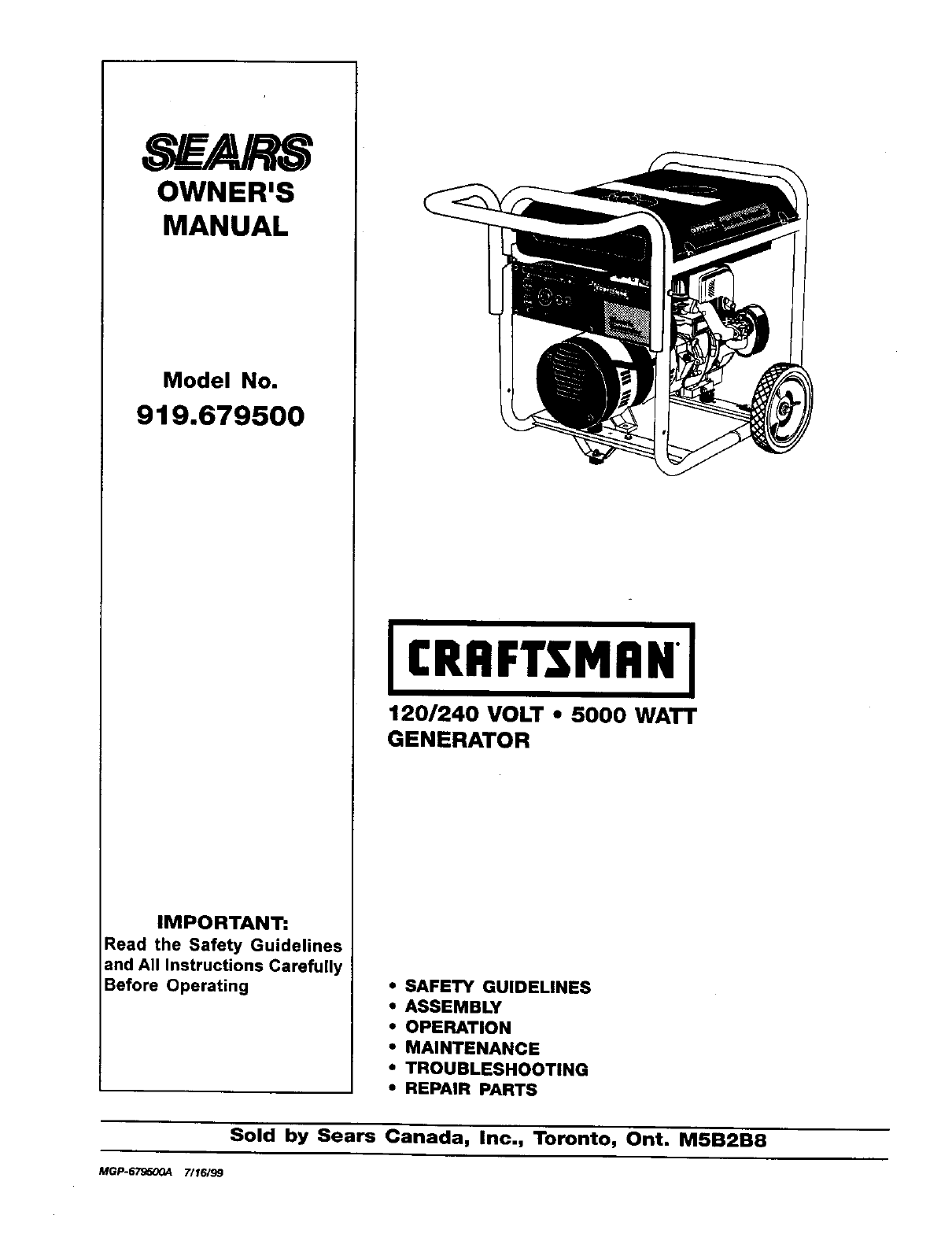
1201240 VOLT " 5000 WATT
GENERATOR
•SAFETY GUIDELINES
•ASSEMBLY
•OPERATION
•MAINTENANCE
• TROUBLESHOOTING
•REPAIR PARTS
Sold by Sears Canada, Inc., Toronto, Ont. M5B2B8
MGP-_ 7/16199
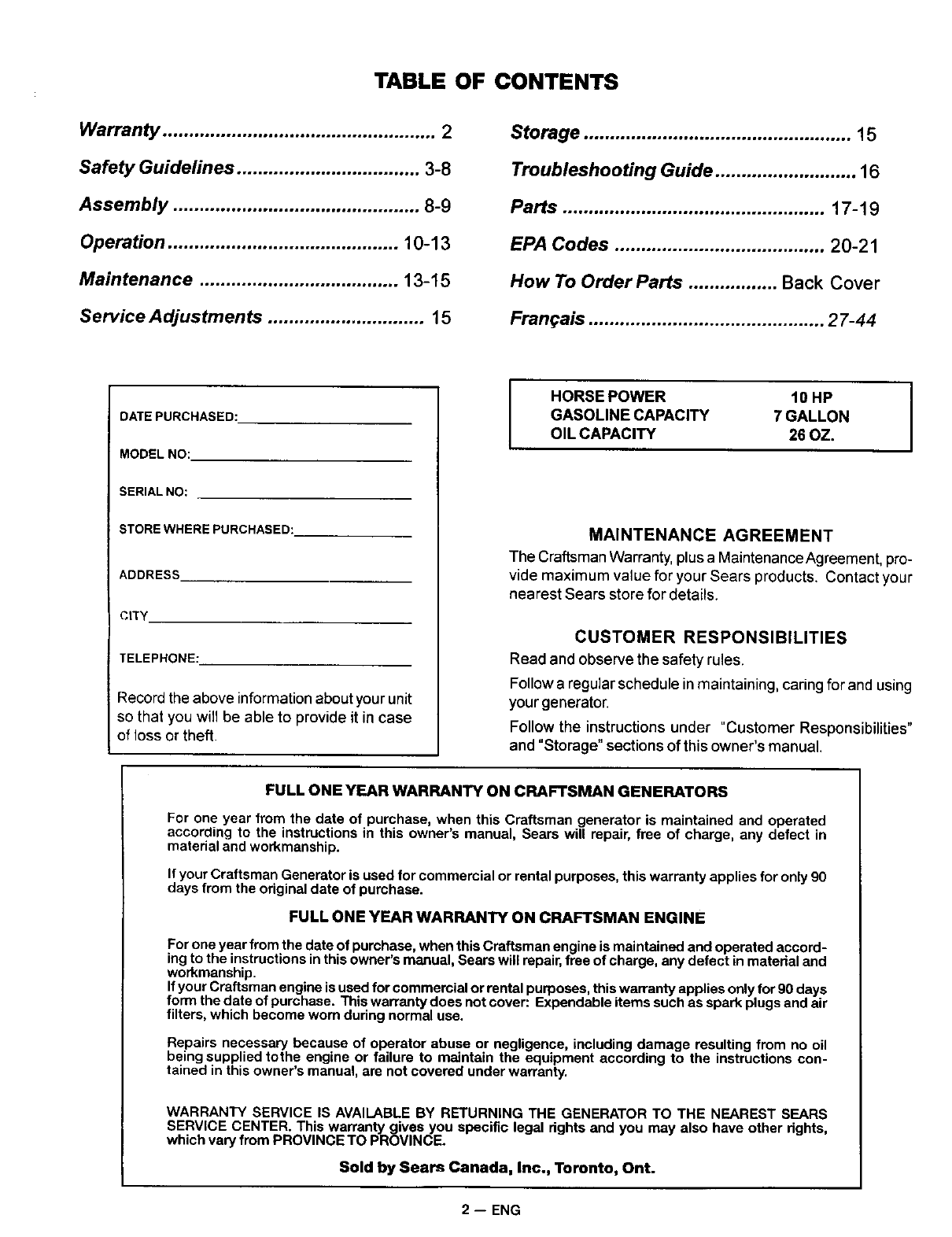
TABLE OF CONTENTS
Warranty .................................................... 2
Safety Guidelines ................................... 3-8
Assembly ............................................... 8-9
Operation ............................................ 10-13
Maintenance ...................................... 13-15
Service Adjustments ............................o . 15
Storage ................................................... 15
Troubleshooting Guide ........................... 16
Parts .................................................. 17-19
EPA Codes ........................................ 20-21
How To Order Parts ................. Back Cover
Fran_ais ............................................. 27-44
DATE PURCHASED:
MODEL NO:
SERIAL NO:
STORE WHERE PURCHASED:
ADDRESS
CtTY
TELEPHONE:
Record the above information about your unit
so that you wilt be able to provide it in case
of loss or theft
I
HORSE POWER 10 HP I
GASOLINE CAPACITY 7 GALLON I
OIL CAPACITY 26 OZ.
MAINTENANCE AGREEMENT
The Craftsman Warranty, plus a MaintenanceAgreement, pro-
vide maximum value for your Sears products. Contact your
nearest Sears store for details.
CUSTOMER RESPONSIBILITIES
Read and observe the safety rules.
Followa regular schedule in maintaining, caringfor and using
your generator.
Follow the instructions under "Customer Responsibilities"
and "Storage"sections of thisowner's manual.
FULL ONE YEAR WARRANTY ON CRAFTSMAN GENERATORS
For one year from the date of purchase, when this Craftsman generator is maintained and operated
according to the instructions in this owner's manual, Sears will repair, free of charge, any defect in
material and workmanship.
If your Craftsman Generator is used for commercial or rental purposes, this warranty applies for only 90
days from the original date of purchase.
FULL ONE YEAR WARRANTY ON CRAFTSMAN ENGINE
For one year from the date of purchase, when this Craftsman engine is maintained and operated accord-
ing to the instructions in this owner's manual, Sears will repair, free of charge, any defect in material and
workmanship.
If your Craftsman engine is used for commercial or rental purposes, this warranty applies only for 90 days
form the date of purchase. This warranty does not cover: Expendable items such as spark plugs and air
filters, which become worn during normal use.
Repairs necessary because of operator abuse or negligence, including damage resulting from no oil
being supplied tothe engine or failure to maintain the equipment according to the instructions con-
tained in this owner's manual, are not covered under warranty.
WARRANTY SERVICE IS AVAILABLE BY RETURNING THE GENERATOR TO THE NEAREST SEARS
SERVICE CENTER. This warranty gives you specific legal rights and you may also have other rights,
which vary from PROVINCE TO PROVINCE.
Sold by Sears Canada, Inc., Toronto, Ont.
2 -- ENG
SAFETY GUIDELINES - DEFINITIONS
This manualcontainsinformationthat
is important for you to know and
understand.This informationrelates
to protecting YOUR SAFETY and
PREVENTING EQUIPMENT
PROBLEMS. To help yourecognize
thisinformation,we usethesymbols
to the right.Please readthe manual
and payattentionto these sections.
I A DANGER I
URGENT SAFETY INFORMATION - AHAZ-
ARD THAT WILL CAUSE SERIOUS INJURY
OR LOSS OF LIFE.
I AWARNING I
IMPORTANT SAFETY INFORMATION - A
HAZARD THAT MIGHT CAUSE SERIOUS
INJURY OR LOSS OF LIFE.
I _I_CAUTION I
Information for preventing damage to
equipment.
I NOTE I
Information that you should
pay special attention to,
IMPORTANT SAFETY INSTRUCTIONS
aSAVE THESE INSTRUCTIONS •
When using this product basic precautions should always be followed
including the following:
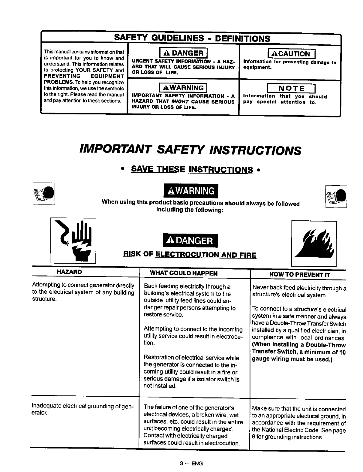
RISK OF ELECTROCUTION AND FIRE
HAZARD
Attempting to connect generator directly
to the electrical system of any building
structure.
Inadequate electrical grounding of gen-
erator.
WHAT COULD HAPPEN
Back feeding electricitythrough a
building's electrical system to the
outside utilityfeed lines could en-
danger repair persons attemptingto
restore service.
Attempting to connect to the incoming
utility service could result in electrocu-
tion.
Restoration of electrical service while
the generator is connected to the in-
coming utilitycould result in a fire or
serious damage if a isolator switch is
not installed.
The failure of one of the generator's
electrical devices, abroken wire, wet
surfaces, etc. could result in the entire
unit becoming electrically charged.
Contact with electrically charged
surfaces could result in electrocution.
HOW TO PREVENT IT
Never back feed electricitythrougha
structure's electrical system.
To connect to a structure's electrical
system in a safe manner and always
have a Double-Throw TransferSwitch
installed by a qualified electrician, in
compliance with local ordinances.
(When installing aDouble-Throw
Transfer Switch, a minimum of 10
gauge wiring must be used.)
Make sure that the unit is connected
to an appropriate electrical ground, in
accordance with the requirement of
the National ElectricCode. See page
8for grounding instructions.
3 -- ENG
READ AND UNDERSTAND ALL WARNINGS BEFORE
All'EMPTING TO OPERATE GENERATOR.
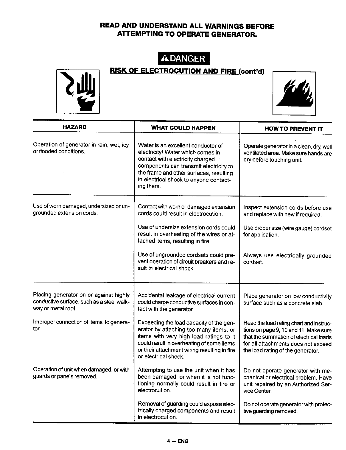
RISK OF ELECTROCUTION AND FIRE (cont'd)
HAZARD
Operation of generator in rain, wet, icy,
or flooded conditions.
Use of worn damaged, undersized or un-
grounded extension cords.
Placing generator on or against highly
conductive surface, such as a steel walk-
way or metal roof.
Improper connection of items to genera-
tor.
Operation of unit when damaged, or with
guards or panels removed.
WHAT COULD HAPPEN
Water is an excellent conductor of
electricity! Water which comes in
contact with electricity charged
components can transmit electricity to
the frame and other surfaces, resulting
in electrical shock to anyone contact-
ing them.
Contact with worn or damaged extension
cords could result in electrocution.
Use of undersize extension cords could
result in overheating of the wires or at-
tached items, resulting in fire.
Use of ungrounded cordsets could pre-
vent operation of circuit breakers and re-
sult in electrical shock.
Accidental leakage of electrical current
could charge conductive surfaces in con-
tact with the generator.
Exceeding the load capacity of the gen-
erator by attaching too many items, or
items with very high load ratings to it
could result in overheating of some items
or their attachment wiring resulting in fire
or electrical shock.
Attempting to use the unit when it has
been damaged, or when it is not func-
tioning normally could result in fire or
electrocution.
Removal of guarding could expose elec-
trically charged components and result
in electrocution.
HOW TO PREVENT IT
Operate generator in a clean, dry,well
ventilated area. Make sure hands are
dry before touching unit.
Inspect extension cords before use
and replace with new if required.
Use proper size (wiregauge) cordset
for application.
Always use electrically grounded
cordset.
Place generator on low conductivity
surface such as a concrete slab.
Read the load rating chart and instruc-
tions on page 9, 10and 11. Make sure
that the summation of electrical loads
for all attachments does not exceed
the load rating of the generator.
Do not operate generator with me-
chanical or electrical problem. Have
unit repaired by an Authorized Ser-
vice Center.
Do not operate generator with protec-
tive guarding removed.
4 -- ENG
READ AND UNDERSTAND ALL WARNINGS BEFORE
ATTEMPTING TO OPERATE (_ENERATOR.
RISK OF FIRE
HAZARD
Attempting to fill the fuel tank while the
engine is running.
Sparks, fire, hot objects
Improper storage of fuel
Inadequate ventilation for generator
Tampering with factory set engine speed
settings.
Overfilling the fuel tank -fuel spillage.
WHAT COULD HAPPEN
Gasoline and gasoline vapors can
become ignited by coming in contact
with hot components such as the
muffler, engine exhaust gases, or from
an electrical spark.
Cigarettes, sparks, fires, or other hot
objects can cause gasoline or gasoline
vapors to ignite.
Improperly stored fuel could lead to ac-
cidental ignition. Fuel impropedy secured
could get into the hands of children or
other unqualified persons.
Materials placed against or near the gen-
erator or operating the generator in ar-
eas where the temperature exceeds 104°
F. ambient can interfere with its proper
ventilation features causing overheating
and possible ignition of the materials.
Engine speed has been factory set to
provide safe operation. Tampering with the
engine speed adjustment could result in
overheating of attachments and could
cause a fire.
Spilled fuel and its vapors can become
ignited from hot surfaces or sparks.
HOWTO PREVENTIT
Turn engine off and allow it to cool
before adding fuel to the tank. Equip
area of operation with a fire extin-
guisher certified to handle gasoline
or fuel fires.
Add fuel to tank inwell ventilated area.
Make sure there are no sources of
ignition near the generator.
Store fuel in acontainer designed to
hold gasoline. Store container in se-
cure location to prevent use by oth-
ers.
Operate generator in a c_ean,dry,well
ventilated area a minimum of four feet
from any objects or wall. DO NOT
OPERATE UNIT INDOORS OR IN
ANY CONFINED AREA.
Never attempt to "speedup" the en-
gine to obtain more performance.
Both the output voltage and frequency
will be thrown out of standard by this
practice, endangering attachments
and the user.
Use care in filling the tank to avoid
spilling fuel. Make sure fuel cap is
secured tightly and check engine
for fuel leaks before starting engine.
Move generator away from refueling
area or any spillage before starting
engine. Allow for fuel expansion.
Keep maximum fuel level ',/,inch
below the tip of the fuel tank. Never
refuel with the engine running.
5 -- ENG
READ AND UNDERSTAND ALL WARNINGS BEFORE
ATTEMPTING TO OPERATE GENERATOR.
Risk of Injury and ProDertv Damage When
Transporting Generator
HAZARD
Fire, Inhalation, Damage to Vehicle
Surfaces
WHAT COULD HAPPEN
Fuel or oil can leak or spill and could
result in fire or breathing hazard, seri-
ous injury or death can result. Fuel or oil
leaks will damage carpet, paint or other
surfaces in vehicles or trailers.
HOW TO PREVENT IT
If generator is equipped with a fuel
shut-off valve, turn the valve to the
off position before transporting to
avoid fuel leaks. If generator is not
equipped with a fuel shut-off valve,
drain the fuel from tank before trans-
porting. Only transport fuel in an CSA
approved container. Always place
generator on a protective mat when
transporting to protect against dam-
age to vehicle from leaks. Remove
generator from vehicle immediately
upon arrival at your destination
RISK OF BREATHING - INHALATION HAZARD
HAZARD
Gasoline engines produce toxic carbon
monoxide exhaust fumes.
WHAT COULD HAPPEN
Breathing exhaust fumes will cause se-
rious injury or death.
HOW TO PREVENT IT
Operate generator in clean, dry, well
ventilated area. Avoid enclosed areas
like garages, basements, storage
sheds, etc., which lack asteady ex-
change of air. Never operate unit in a
location occupied by humans or ani-
mals. Keep children, pets and others
away from area of operating unit.
6 -- ENG
READ AND UNDERSTAND ALL WARNINGS BEFORE
ATTEMPTING TO OPERATE GENERATOR.
RISK OF UNSAFE OPERATION
HAZARD
Operation of generator in careless
manne[
Operationof voltage sensitive appliances
withoutavoltage surge protecto[
WHAT COULD HAPPEN
All sources of energy include the poten-
tial for injury. Unsafe operation or main-
tenance of your generator could lead to
serious injury or death to you or others.
Any gasoline operated household gen-
erator will incur voltage variations caus-
ing damage to voltage sensitive appli-
ances or result in fire.
HOW TO PREVENT IT
• Review and understandaUof the
operating instructions and warn-
ings in this manual.
• Become familiar with the operation
and controls of the generator.
Know how to shut it off quickly.
•Equip area of operation with a fire
extinguisher certifiedto handle
gasoline or fuel fires.
• Keep children or others away from
the generator at all times.
Always use U.L listed voltage pro-
tector to connect voltage sensitive
appliances (TV, computer, stereo,
etc.). Failure to use a U.L listed volt-
age surge protector will void the war-
ranty on your generator.
Notice: Amultiple outlet strip is not
asurge protector make sureyou use
a U.L. listed voltage surge protector.
RISK OF HOT SURFACES
HAZARD
Contact with hot engine and generator
components.
HAZARD
act with moving parts can result in
serious injury.
WHAT COULD HAPPEN
Contact with hot surfaces, such as en-
gines exhaust components, could result
in serious burns.
HOW TO PREVENT IT
Dudng operation, touch only the con-
trot surfaces of the generator. Keep
children away from the generator at
all times. They may not be able to
recognize the hazards of this prod-
uct.
RISK OF MOVING PARTS
WHAT COULD HAPPEN
The generator contains parts which ro-
tate at high speed during operation.
These parts are covered by guarding to
prevent injury.
HOW TO PREVENT IT
Never operate generator withguard-
ing or cover plates removed. Avoid
wearing loose fitting clothingor jew-
elry which could be caught by mov-
ing parts.
7 -- ENG
READ AND UNDERSTAND ALL WARNINGS BEFORE
ATTEMPTING TO OPERATE GENERATOR.
y, RISK FROM LIFTING
HAZARD
Lifting a very heavy object.
WHAT COULD HAPPEN
Serious injury can result from attempt-
ing to lift too heavy an object.
HOW TO PREVENT IT
The generator is too heavy to be lifted
by one person. Obtain assistance
from others before you try to move it.
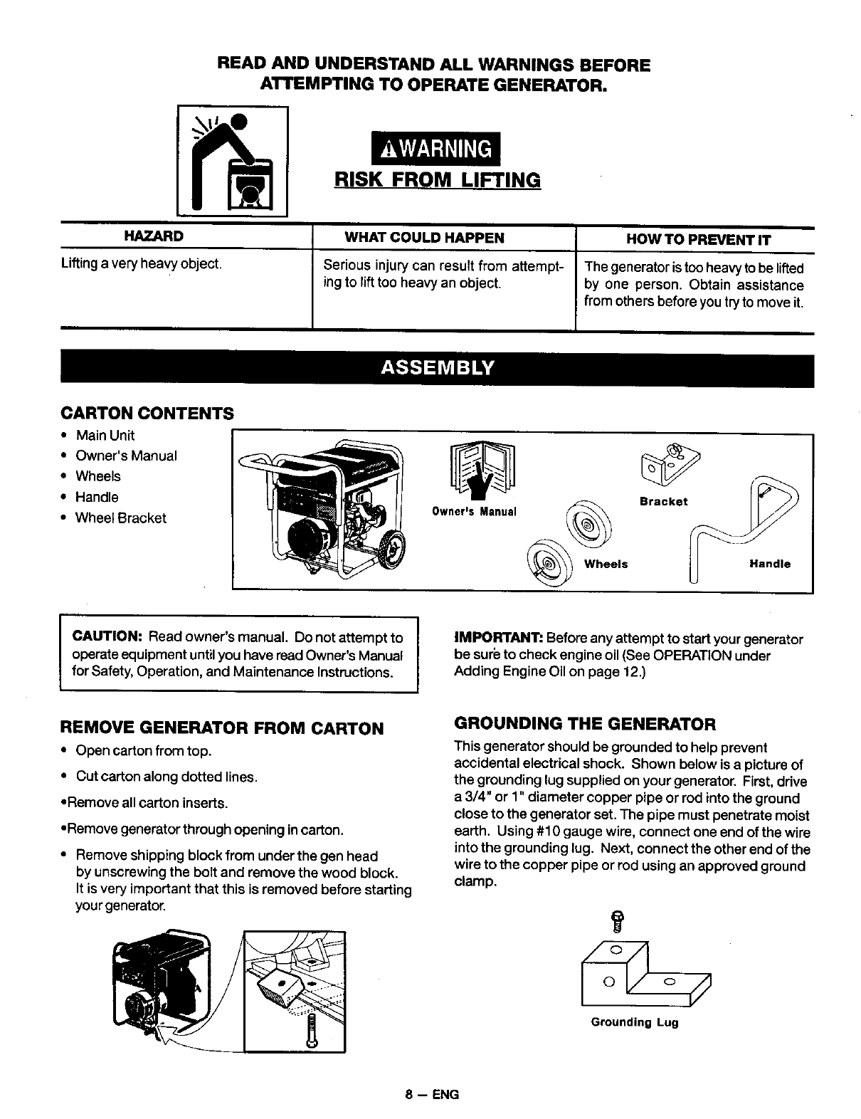
CARTON CONTENT, _
• Main Unit
• Owner's Manual
• Wheels
• Handle
• Wheel Bracket
Bracket
OwnerJs Manual __Wheels Handle
CAUTION: Read owner's manual. Do not attempt to
operate equipment until you have read Owner's Manual
for Safety, Operation, and Maintenance Instructions.
REMOVE GENERATOR FROM CARTON
• Open carton from top.
• Cut carton along dotted lines.
•Remove all carton inserts.
•Remove generator through opening in carton.
• Remove shipping block from under the gen head
by unscrewing the bolt and remove the wood block.
It is very important that this is removed before starting
your generator.
IIMPORTANT: Before any attempt to start your generator
be sur_ to check engine oil (See OPERATION under
Adding Engine Oil on page 12.)
GROUNDING THE GENERATOR
This generator should be grounded to help prevent
accidental electrical shock. Shown below is a picture of
the grounding lug supplied on your generator. First, drive
a 3/4" or 1" diameter copper pipe or rod into the ground
close to the generator set. The pipe must penetrate moist
earth. Using #10 gauge wire, connect one end of the wire
into the grounding lug. Next, connect the other end of the
wire to the copper pipe or rod using an approved ground
clamp.
Grounding Lug
8 -- ENG
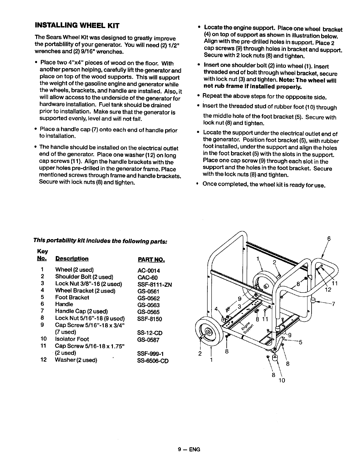
INSTALLING WHEEL KIT
The Sears Wheel Kit was designed to greatly improve
the portablility of your generator. You will need (2) 1/2"
wrenches and (2) 9/16" wrenches.
• Place two 4"x4" pieces of wood on the floor. With
another person helping, carefully lift the generator and
place on top of the wood supports. This will support
the weight of the gasoline engine and generator while
the wheels, brackets, and handle are installed. Also, it
will allow access to the underside of the generator for
hardware installation. Fuel tank should be drained
prior to installation. Make sure that the generator is
supported evenly, level and will not fall.
•Place a handle cap (7) onto each end of handle prior
to installation.
•The handle should be installed on the electrical outlet
end of the generator. Place one washer (12) on long
cap screws (11). Align the handle brackets with the
upper holes pre-drilled in the generator frame. Place
mentioned screws through frame and handle brackets.
Secure with lock nuts (8) and tighten.
Locate the engine support. Place one wheel bracket
(4) on top of support as shown in illustration below.
Align with the pre-ddlled holes insupport. Place 2
cap screws (9) through holes in bracket and support.
Secure with 2 lock nuts (8) and tighten.
Insert one shoulder bolt (2) into wheel (1). insert
threaded end of bolt through wheel bracket, secure
with lock nut (3) and tighten. Note: The wheel will
not rub frame if installed property.
•Repeat the above steps for the oppposite side.
•insert the threaded stud of rubber foot (10) through
the middle hole of the foot bracket (5). Secure with
lock nut (8) and tighten.
Locate the support under the electrical outlet end of
the generator. Position foot bracket (5), with rubber
foot installed, under the support and align the holes
in the foot bracket (5) with the slots in the support.
Place one cap screw (9) through each slot inthe
support and the holes in the foot bracket. Secure
with the lock nuts (8) and tighten.
Once completed, the wheel kit is ready for use.
This portability kit includes the following parts:
Key
No. Descrh_tion ARTp_AR_T_r_.
1 Wheel (2 used) AC-0014
2 Shoulder Bolt (2 used) CAC-60
3 Lock Nut 3/8"-16 (2 used) SSF-8111-ZN
4 Wheel Bracket (2 used) GS-0551
5 Foot Bracket GS-0562
6 Handle GS-0563
7 Handle Cap (2 used) GS-0555
8 Lock Nut 5/16"-18 (9 used) SSF-6150
9 Cap Screw 5/16"-18 x 3/4"
(7 used) SS-12-CD
10 Isolator Foot GS-0587
11 Cap Screw 5/16-18 x 1.75"
(2 used) SSF-999-1
12 Washer (2 used) SS-6506-CD
2 8
10
11
12
9-- ENG
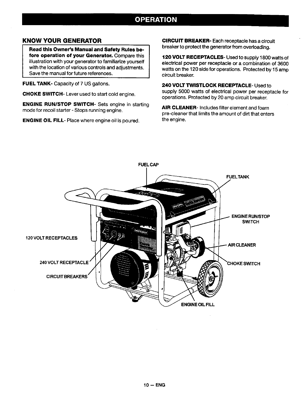
KNOW YOUR GENERATOR
Read this Owner's Manual and Safety Rules be-
fore operation of your Generator. Compare this
illustration with your generator to famUiarize yourself
with the location of various controls and adjustments.
Save the manual for future references.
FUEL TANK- Capacity of 7US gallons.
CHOKE SWITCH- Lever used to start cold engine.
ENGINE RUN/STOP SWITCH- Sets engine in starting
mode for recoil starter -Stops running engine.
ENGINE OIL FILL- Place where engine oil is poured.
CIRCUIT BREAKER- Each receptacle has a circuit
breaker to protect the generator from overloading.
120 VOLT RECEPTACLES- Used to supply 1800 watts of
electrical power per receptacle or a combination of 3600
watts on the 120 sidefor operations. Protected by 15 amp
circuit breaker.
240 VOLT TWISl"LOCK RECEPTACLE- Used to
supply 5000 watts of electrical power per receptacle for
operations. Protected by 20 amp circuit breaker.
AIR CLEANER- Includes filter element and foam
pre-cleaner that limits the amount of dirt that enters
the engine.
FUELCAP
FUELTANK
ENGINE RUN/STOP
SWITCH
120VOLTRECEPTACLES
ENGINE OIL FILL
10 -- ENG
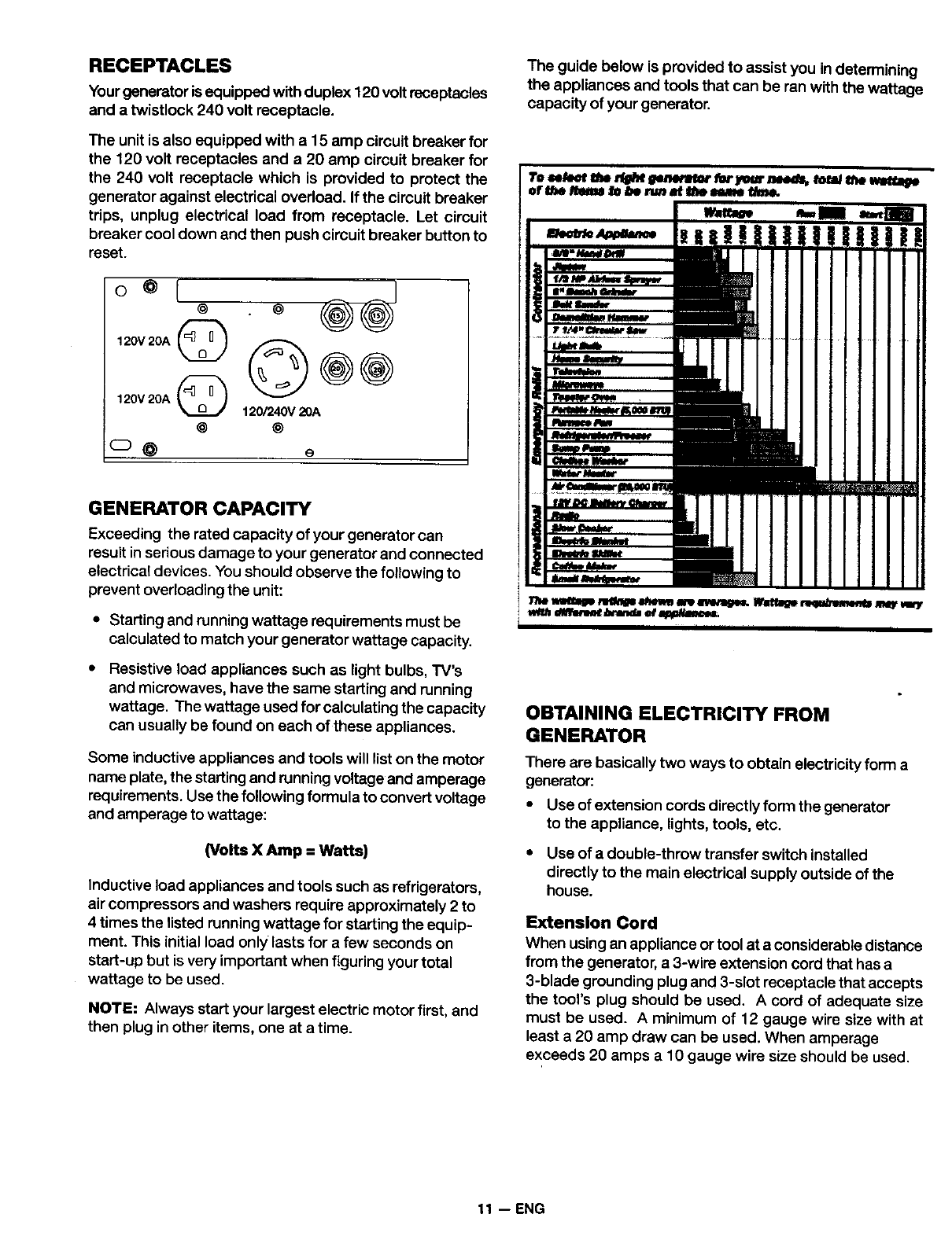
RECEPTACLES
Yourgenerator is equipped with duplex 120 volt receptacles
and a twistlock 240 volt receptacle.
The unit is also equipped with a15 amp circuit breaker for
the 120 volt receptacles and a 20 amp circuit breaker for
the 240 volt receptacle which is provided to protect the
generator against electrical overload. If the circuit breaker
trips, unplug electrical load from receptacle. Let circuit
breaker cool down and then push circuit breaker button to
reset.
120V 20A (_
120V20A _120/240V20A
@ @
_O e
The guide below is provided to assist you in determining
the appliances and tools that can be ran with the wattage
capacity of your generator.
_ _ me n_'_ I_w=mr fer_r m feral _ Q
or I_e/h_m hIm nm at't_telame ffmL
GENERATOR CAPACITY
Exceeding the rated capacityof your generatorcan
result in serious damage to your generator and connected
electrical devices. You should observe the following to
prevent overloading the unit:
• Starting and running wattage requirements must be
calculated to match your generator wattage capacity.
Resistive load appliances such as light bulbs, TV's
and microwaves, have the same starting and running
wattage. The wattage used for calculating the capacity
can usually be found on each of these appliances.
Some inductive appliances and tools will list on the motor
name plate, the starting and running voltage and amperage
requirements. Use the following formula to convert voltage
and amperage to wattage:
(Volts X Amp = Watts)
Inductive load appliances and tools such as refrigerators,
air compressors and washers require approximately 2 to
4 times the listed running wattage for starting the equip-
ment. This initial load onl_/lasts for a few seconds on
start-up but is very important when figuring your total
wattage to be used.
NOTE: Always start your largest electric motor first, and
then plug in other items, one at a time.
I ii II i
OBTAINING ELECTRICITY FROM
GENERATOR
There are basically two ways to obtain electricity form a
generator:
• Use of extension cords directly form the generator
to the appliance, lights, tools, etc.
•Use of a double-throw transfer switch installed
directly to the main electrical supply outside of the
house.
Extension Cord
When using an appliance or tool at a considerable distance
from the generator, a 3-wire extension cord that has a
3-blade grounding plug and 3-slot receptacle that accepts
the tool's plug should be used. A cord of adequate size
must be used. Aminimum of 12 gauge wire size with at
least a 20 amp draw can be used. When amperage
exceeds 20 amps a 10 gauge wire size should be used.
11 -- ENG
Connecting Generator To Main Electrical
Supply
Potential hazards exist when a electrical generator is con-
nected to the main electrical supply coming into the house.
It is at that point that the generator could feed back into the
utility company's system causing possible electrocution of
workers who are repairing electrical lines. To avoid back
feeding of electricity into utility systems, a double-throw
transfer switch should be installed between the genera-
tor and utility power. This device should be installed by a
licensed electrician and in compliance with all local electri-
calcodes.
NOTE: When installing a Double-Throw Transfer Switch,
aminimum of 10 gauge wiring must be used.
BEFORE STARTING ENGINE
CAUTION: Always check engine oil level before
every start, Running engine low of oil or out of oil
could result in serious damage to the engine.
Adding Engine Oil
Your generator has been shipped without oil in the
engine. Begin by removing the oil dipstick and plug. Start
pouring the oil in slowly.
The engine will hold approximately 26 ounces of oil. To
check the oil, clean and replace the dipstick. Do not
screw the dip stick in when checking the oil level. Next,
remove the dipstick to check the level. The oil dipstick is
clearly marked with lines that tell you when the engine
has enough oil. Do not fill above this point.
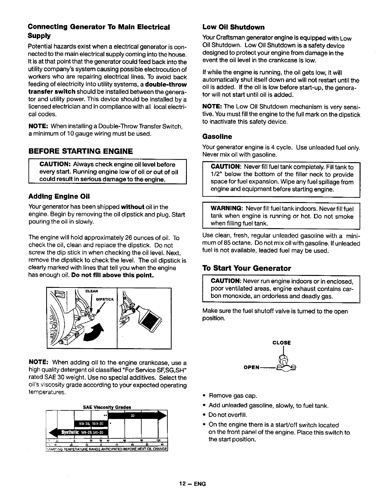
NOTE: When adding oil to the engine crankcase, use a
high quality detergent oil classified "For Service SF,SG,SH"
rated SAE 30 weight. Use no special additives. Select the
oil's viscosity grade according to your expected operating
temperatures.
.. m= •
I
4
,IART_NG TEMPERATURE RANOE ANTICIPATED BEFORE NEXT OIL CHANG[
Low Oil Shutdown
Your Craftsman generator engine is equipped with Low
Oil Shutdown, Low Oil Shutdown is a safety device
designed to protect your engine from damage inthe
event the oil level in the crankcase is low.
If while the engine is running, the oil gets low, it will
automatically shut itself down and will not restart until the
oil is added. If the oil Is low before start-up, the genera-
tor will not start until oil is added.
NOTE: The Low Oil Shutdown mechanism is very sensi-
tive. You must fill the engine to the full mark on the dipstick
to inactivate this safety device,
Gasoline
Your generator engine is 4 cycle. Use unleaded fuel only,
Never mix oil with gasoline,
CAUTION: Never fill fuel tank completely. Filltank to
1/2" below the bottom of the filler neck to provide
space for fuel expansion. Wipe any fuel spillage from
engine and equipment before starting engine.
IARNING: Neverfillfueltankindoors. Neverfiltfuel I
tank when engine is running or hot. Do not smoke
when filling fuel tank.
Use clean, fresh, regular unleaded gasoline with a mini-
mum of 85 octane. Do not mix oil with gasoline. If unleaded
fuel is not available, leaded fuel may be used.
To Start Your Generator
CAUTION: Never run engine indoors or in enclosed,
poor ventilated areas, engine exhaust contains car-
bon monoxide, an ordorless and deadly gas.
Make sure the fuel shutoff valve is turned to the open
position.
CLOSE
OPEN--_
•Remove gas cap.
•Add unleaded gasoline, slowly, to fuel tank.
•Do not overfill.
• On the engine there is a start/off switch located
on the front panel of the engine. Place this switch to
the start position.
12 -- ENG
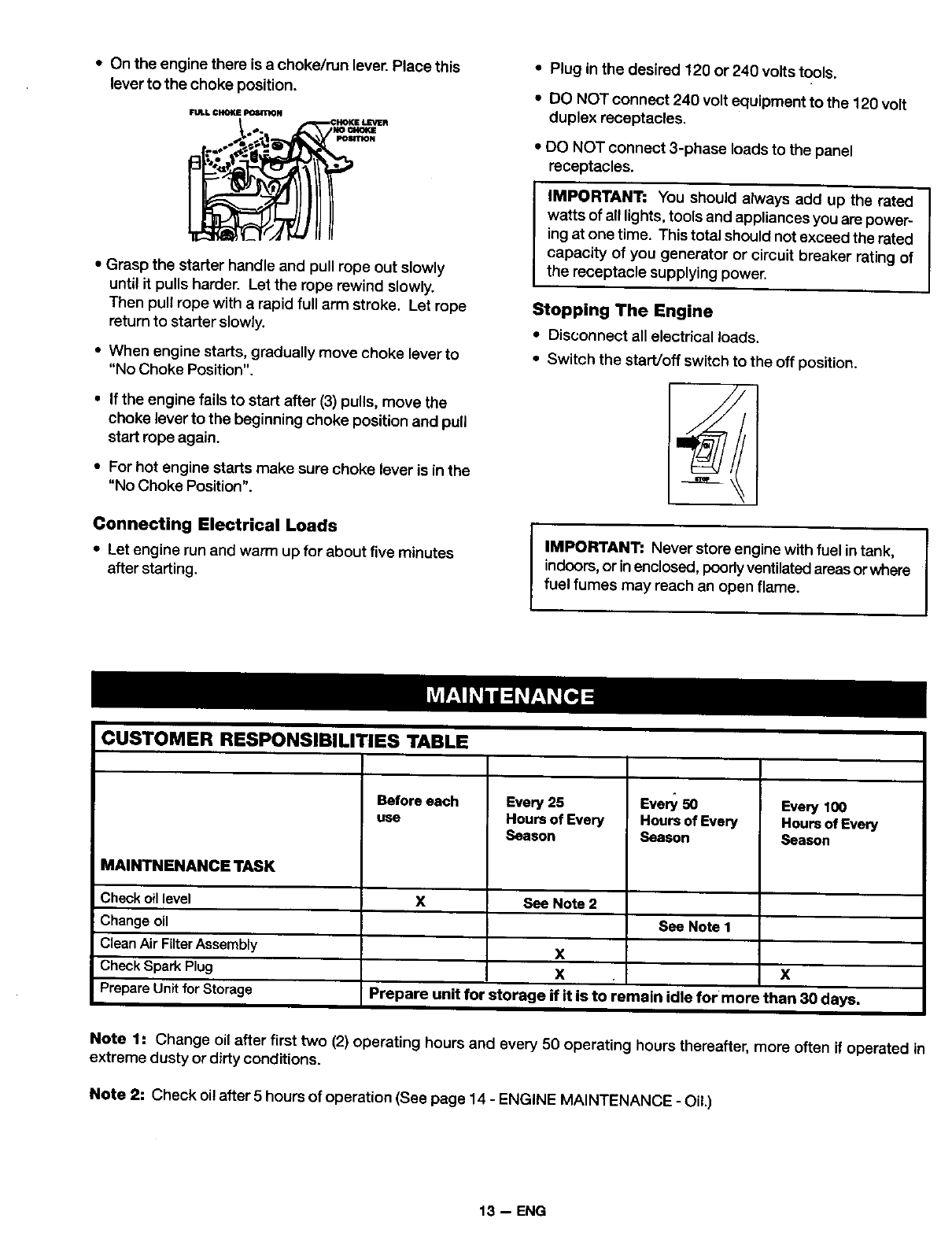
•On the engine there is a choke/run lever. Place this •Plug in the desired 120 or 240 volts tools.
lever to the choke position.
FULl. CHOKE Pt_tTION
• Grasp the starter handle and pull rope out slowly
until it pulls harder. Let the rope rewind slowly.
Then pull rope with arapid full arm stroke. Let rope
return to starter slowly.
• When engine starts, gradually move choke lever to
"No Choke Position".
• If the engine fails to start after (3) pulls, move the
choke lever to the beginning choke position and pull
start rope again.
•For hot engine starts make sure choke lever is in the
"No Choke Position".
Connecting Electrical Loads
•Let engine run and warm up for about five minutes
after starting.
•DO NOT connect 240 volt equipment to the 120 volt
duplex receptacles.
• DO NOT connect 3-phase loads to the panel
receptacles.
IMPORTANT: You should always add up the rated
watts of all lights, tools and appliances you are power-
ing at one time. This total should not exceed the rated
capacity of you generator or circuit breaker rating of
the receptacle supplying power.
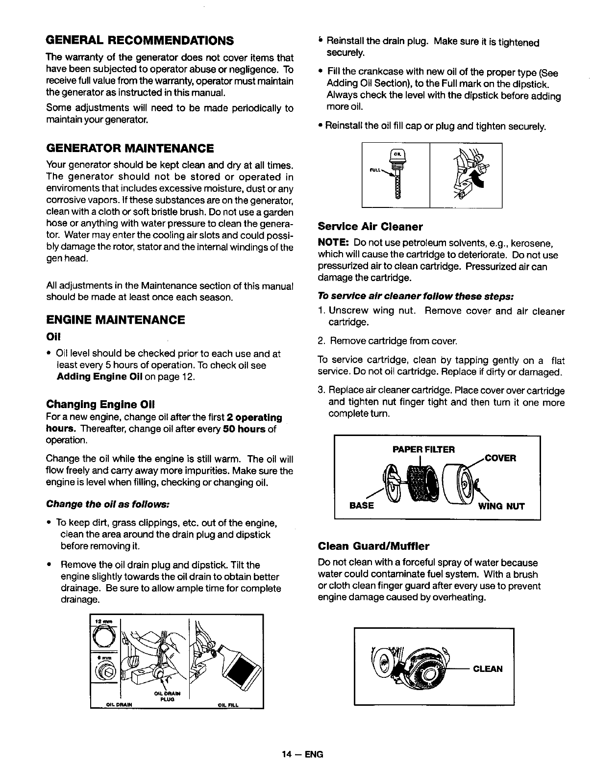
Stopping The Engine
• Disconnect all electrical loads.
• Switch the start/off switch to the off position.
IMPORTANT:. Never store engine with fuel intank,
indoors,or in enclosed, poodyventilatedareas orwhere
fuel fumes may reach an open flame.
CUSTOMER RESPONSIBILITIES TABLE
Before each Every25 Every 50 Every 100
use Hours of Every Hours of Every Hoursof Every
Season Season Season
MAINTNENANCE TASK
Checkoillevel X See Note 2
Change oil See Note 1
CleanAir FilterAssembly X
Check Spark Plug X X
PrepareUnit forStorage Prepare unit for storage If it is to remain idle for more than 30 days.
Note 1: Change oil after first two (2) operating hours and every 50 operating hours thereafter, more often if operated in
extreme dusty or dirty conditions.
Note 2: Check oil after 5 hours of operation (See page 14 - ENGINE MAINTENANCE -Oil.)
13 -- ENG
GENERAL RECOMMENDATIONS
The warranty of the generator does not cover items that
have been subjected to operator abuse or negligence. To
receivefull value from the warranty,operator must maintain
the generator as instructed in this manual.
Some adjustments will need to be made periodically to
maintain your generator.
GENERATOR MAINTENANCE
Your generator should be kept clean and dry at all times.
The generator should not be stored or operated in
enviroments that includes excessive moisture, dust or any
corrosive vapors. If these substances are on the generator,
clean with a cloth or soft bristle brush. Do not use a garden
hose or anything with water pressure to clean the genera-
tor. Water may enter the cooling air slots and could possi-
bly damage the rotor, stator and the internal windings of the
gen head.
All adjustments in the Maintenance section of this manual
should be made at least once each season.
ENGINE MAINTENANCE
Oil
•Oil level should be checked prior to each use and at
least every 5 hours of operation. To check oil see
Adding Engine Oil on page 12.
Changing Engine Oil
For anew engine, change oil after the first 2 operating
hours. Thereafter, change oil after every 50 hours of
operation.
Change the oil while the engine is still warm. The oil will
flow freely and carry away more impurities. Make sure the
engine is level when filling, checking or changing oil.
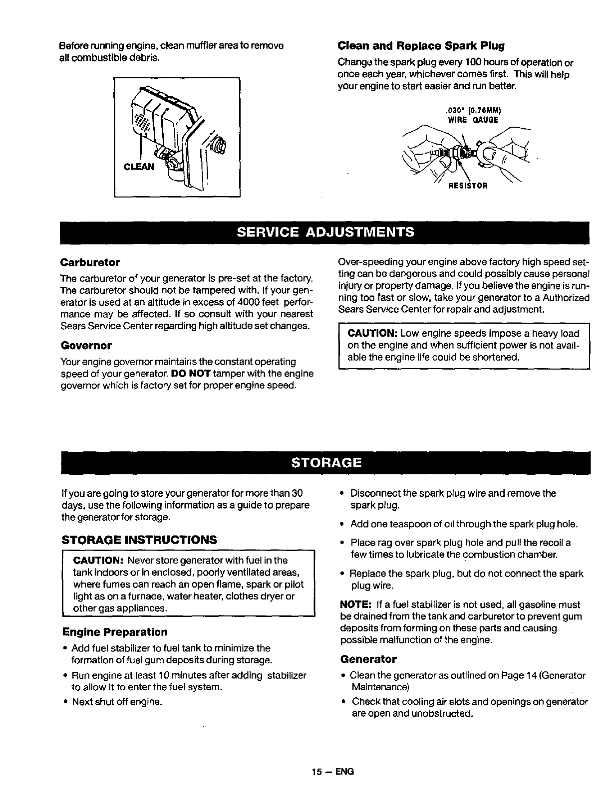
Change the oil as follows:
• To keep dirt, grass clippings, etc. out of the engine,
clean the area around the drain plug and dipstick
before removing it.
Remove the oil drain plug and dipstick. Tilt the
engine slightly towards the oil drain to obtain better
drainage. Be sure to allow ample time for complete
drainage.
_2_ J
O_ ORA_
PLUG
OIL DRAIN OIL FILl.
Reinstall the drain plug. Make sure it is tightened
securely.
•Fillthe crankcase with new oil of the proper type (See
Adding Oil Section), to the Full mark on the dipstick.
Always check the level with the dipstick before adding
more oil.
• Reinstall the oil fill cap or plug and tighten securely.
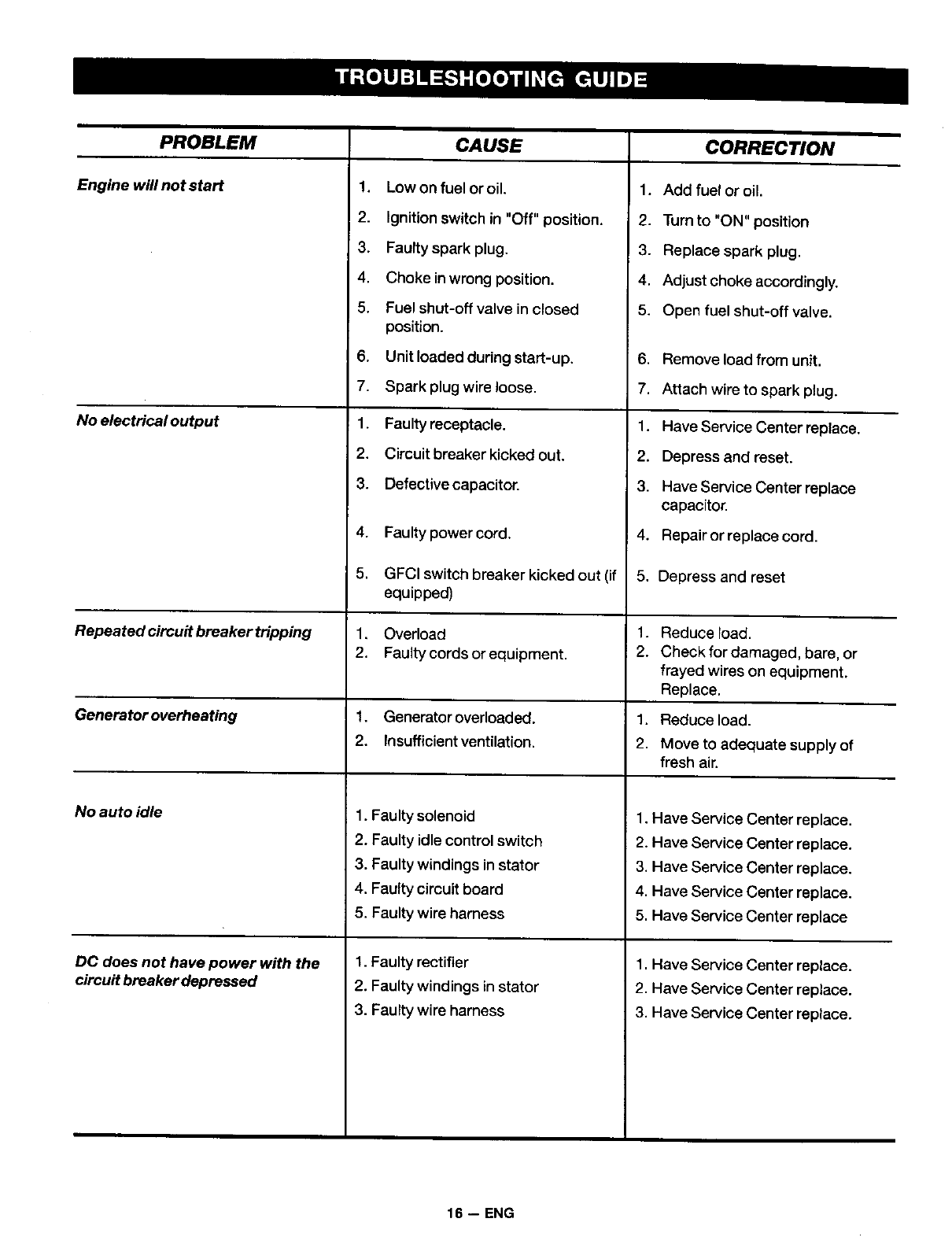
Service Air Cleaner
NOTE: Do not use petroleum solvents, e.g., kerosene,
which will cause the cartddge to deteriorate. Do not use
pressurized airto clean cartridge. Pressurized air can
damage the cartridge.
To service air cleaner follow these steps:
1. Unscrew wing nut. Remove cover and air cleaner
cartridge.
2. Remove cartridge from cover.
To service cartridge, clean by tapping gently on a flat
service. Do not oil cartridge. Replace if dirty or damaged.
3. Replace air cleaner cartridge. Place cover over cartridge
and tighten nut finger tight and then turn it one more
complete turn.
PAPER FILTER
BAS_ _COVER
Q_WlNG NUT
Clean Guard/Muffler
Do not clean with a forceful spray of water because
water could contaminate fuel system. With abrush
or cloth clean finger guard after every use to prevent
engine damage caused by overheating.
'-_ CLEAN
14 -- ENG
Before running engine, clean muffler area to remove
all combustible debris. Clean and Replace Spark Plug
Change the spark plug every 100 hours of operation or
once each year, whichever comes first. This will help
your engine to start easier and run better.
.030" (0,76MM)
WIRE QAUGE
RESISTOR
Carburetor
The carburetor of your generator is pre-set at the factory.
The carburetor should not be tampered with. If your gen-
erator is used at an altitude in excess of 4000 feet perfor-
mance may be affected. If so consult with your nearest
Sears Service Center regarding high altitude set changes.
Governor
Your engine governor maintains the constant operating
speed of your generator. DO NOT tamper with the engine
governor which is factory set for proper engine speed.
Over-speeding your engine above factory high speed set-
ting can be dangerous and could possibly cause personal
injury or property damage. If you believe the engine is run-
ning too fast or slow, take your generator to a Authorized
Sears Service Center for repair and adjustment.
ICAUTION: Low engine speeds impose a heavy load I
I
on the engine and when sufficient power is not avail- I
able the engine life could be shortened.
If you are going to store your generator for more than 30
days, use the following information as a guide to prepare
the generator for storage.
STORAGE INSTRUCTIONS
IAUTION: Never store generator with fuel in the
tank indoors or inenclosed, poorly ventilated areas,
where fumes can reach an open flame, spark or pilot
light as on a furnace, water heater, clothes dryer or
other gas appliances.
Engine Preparation
•Add fuel stabilizer to fuel tank to minimize the
formation of fuel gum deposits during storage.
• Run engine at least 10 minutes after adding stabilizer
to allow it to enter the fuel system.
•Next shut off engine.
• Disconnect the spark plug wire and remove the
spark plug.
• Add one teaspoon of oil through the spark plug hole.
• Place rag over spark plug hole and pull the recoil a
few times to lubricate the combustion chamber.
• Replace the spark plug, but do not connect the spark
plug wire.
NOTE: If afuel stabilizer is not used, all gasoline must
be drained from the tank and carburetor to prevent gum
deposits from forming on these parts and causing
possible malfunction of the engine.
Generator
•Clean the generator as outlined on Page 14 (Generator
Maintenance)
•Check that cooling air slots and openings on generator
are open and unobstructed.
15 -- ENG
PROBLEM
Engine will not start
No electrical output
CAUSE
1. Low on fuel or oil.
2. Ignition switch in "Off" position.
3. Faulty spark plug.
4. Choke inwrong position.
5. Fuel shut-off valve in closed
position.
6, Unit loaded during start-up.
7. Spark plug wire loose.
1.
2.
Faulty receptacle.
Circuit breaker kicked out.
CORRECTION
1. Add fuel or oil.
2. Turn to "ON" position
3. Replace spark plug.
4. Adjust choke accordingly.
5. Open fuel shut-off valve.
6. Remove load from unit.
7. Attach wire to spark plug.
1. Have Service Center replace.
2. Depress and reset.
3. Defective capacitor.
4. Faulty power cord.
3. Have Service Center replace
capacitor.
4. Repair or replace cord.
5. GFCI switch breaker kicked out (if 5. Depress and reset
equipped)
Repeated circuit breakertripping 1. Overload 1. Reduce load.
2, Faulty cords or equipment. 2. Check for damaged, bare, or
frayed wires on equipment.
Replace.
Generator overheating 1. Generator overloaded. 1. Reduce load.
2. Insufflcientventilation. 2. Move to adequate supply of
fresh air.
No auto idle
DC does not have power with the
circuit breaker depressed
1, Faulty solenoid
2, Faulty idle control switch
3, Faulty windings in stator
4. Faulty circuit board
5. Faulty wire harness
1. Faulty rectifier
2. Faulty windings in stator
3. Faulty wire harness
1. Have Service Center replace.
2. Have Service Center replace.
3. Have Service Center replace.
4. Have Service Center replace.
5. Have Service Center replace
1. Have Service Center replace.
2. Have Service Center replace.
3. Have Service Center replace.
16 -- ENG
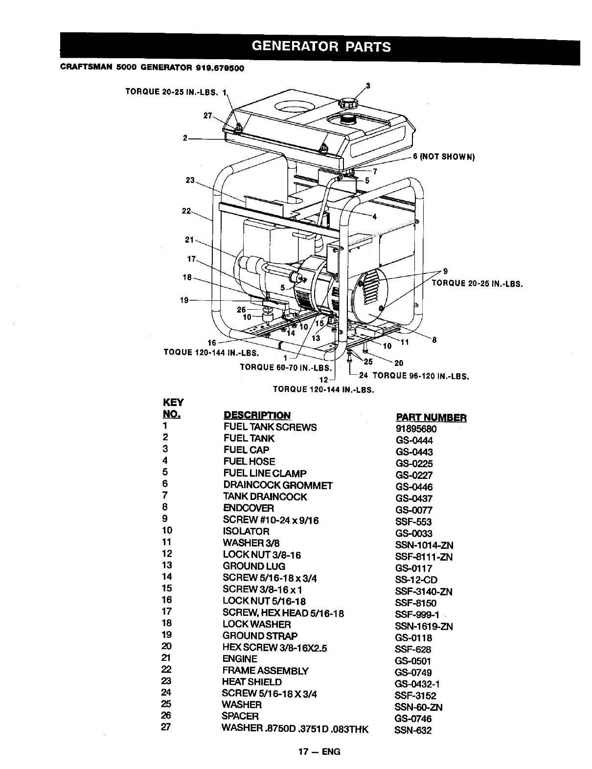
CRAFTSMAN 5000 GENERATOR 919,679500
TORQUE 20-25 IN.-LBS. 1
(NOT SHOWN)
20-26 IN.-LBS.
16
TOQUE 120-144 IN.-LBS.
TORQUE 60-70 IN.-LBS. 20
12 TORQUE 96-120 IN.-LBS.
TORQUE 120-144 IN.-LBS.
KEY
NO.
1
2
3
4
5
6
7
8
9
10
11
12
13
14
15
15
17
18
19
2O
21
22
23
24
25
26
27
FUEL TANK SCREWS 91895680
FUEL TANK GS-0444
FUEL CAP GS-0443
FUEL HOSE GS-0225
FUEL LINE CLAMP GS-0227
DRAINCOCK GROMMET GS-O446
TANK DRAINCOCK GS-0437
ENDCOVER GS-0077
SCREW #10-24 x 9/16 SSF-553
ISOLATOR GS-0033
WASHER 3/8 SSN-1014-ZN
LOCK NUT 3/8-16 SSF-8111-ZN
GROUND LUG GS-0117
SCREW 5/16-18 x 3/4 SS-12-CD
SCREW 3/8-16 x I SSF-3140-ZN
LOCK NUT 5/16-18 SSF-8150
SCREW, HEX HEAD 5/16-18 SSF-999-1
LOCK WASHER SSN-1619-ZN
GROUND STRAP GS-0118
HEX SCREW 3/8-16)(2.5 SSF-628
ENGINE GS-0501
FRAME ASSEMBLY GS-0749
HEAT SHIELD GS-0432-1
SCREW 5/16-18 X 3/4 SSF-3152
WASHER SSN-60-ZN
SPACER GS-0746
WASHER .8750D .3751 D .083THK SSN-632
17 -- ENG
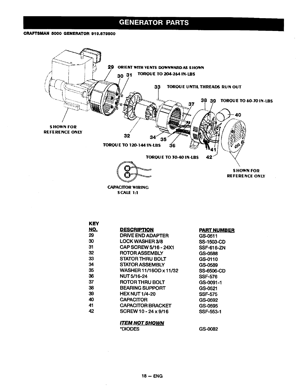
CRAFTSMAN 5000 GENERATOR 919.679500
29 ORIENTWITH VENTS DOWNWARDAS SHOWN
30 31 TOROUETO204-2641N.I.BS
TORQU E U NTIL THREADS RU N OUT
TORQUE TO 60-70 IN-LBS
S HOWN FOR
REFERENCE ONLY /
32 34" 35
TOROU E TO 120-144 IN-LBS
TORQU E TO 30-40 IN-LBS
CAPACITOR WIRING
SCALE 1:1
42
S HOWN FOR
REFERENCE ONLY
KEY
NO_____.
29
3O
31
32
33
34
35
36
37
38
39
4O
41
42
DESCRIPTION
DRIVE END ADAPTER
LOCK WASHER 3/8
CAP SCREW 5/16 -24X1
ROTOR ASSEMBLY
STATOR THRU BOLT
STATOR ASSEMBLY
WASHER 11/16OD x 11/32
NUT 5/16-24
ROTOR THRU BOLT
BEARING SUPPORT
HEX NUT1/4-20
CAPACITOR
CAPACITOR BRACKET
SCREW 10- 24x 9/16
ITEM NOT SHOWN
*DIODES
PART NUMBER
GS-0511
SS-1503-CD
SSF-616-ZN
GS-0588
GS-0110
GS-0589
SS-6506-CD
SSF-576
GS-0091-1
GS-0521
SSF-575
GS-0592
GS-0595
SSF-553-1
GS-0082
18 -- ENG
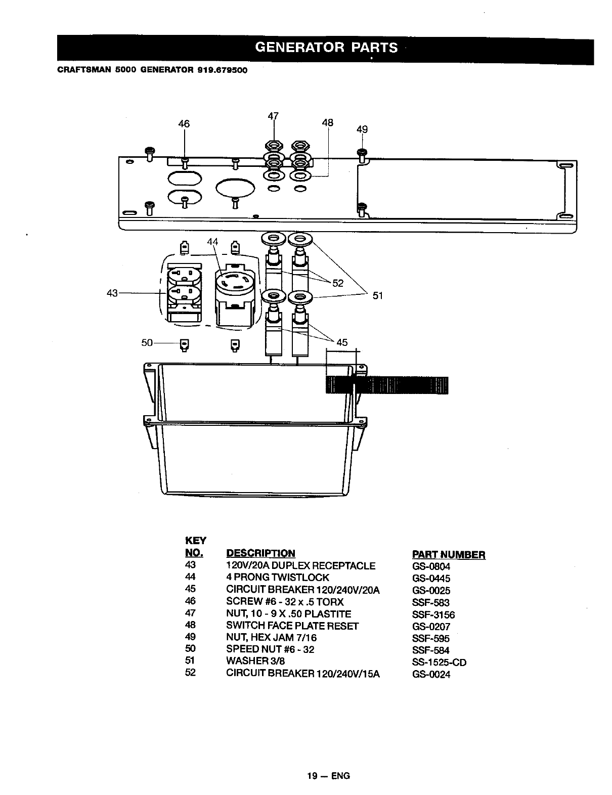
CRAFTSMAN 5000 GENERATOR 919.679500
46 48 49
51
KEY
NO_, DESCRIPTION
43 120V/20A DUPLEX RECEPTACLE
44 4 PRONG TWISTLOCK
45 CIRCUIT BREAKER 120/240V/20A
46 SCREW #6 - 32 x .5 TORX
47 NUT, 10 -9 X .50 PLASTITE
48 SWITCH FACE PLATE RESET
49 NUT, HEX JAM 7116
50 SPEED NUT #6 -32
51 WASH ER 3/8
52 CIRCUIT BREAKER 120/240V/15A
PART
GS-0804
GS-0445
GS-0025
SSF-583
SSF-3156
GS-0207
SSF-595
SSF-584
SS-1525-CD
GS-0024
19 -- ENG
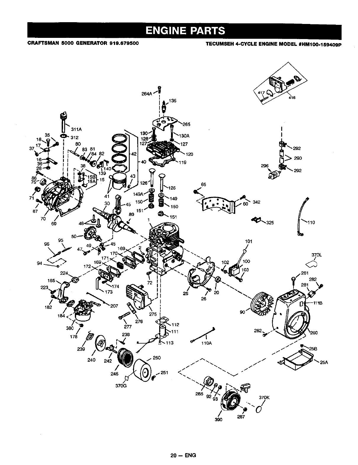
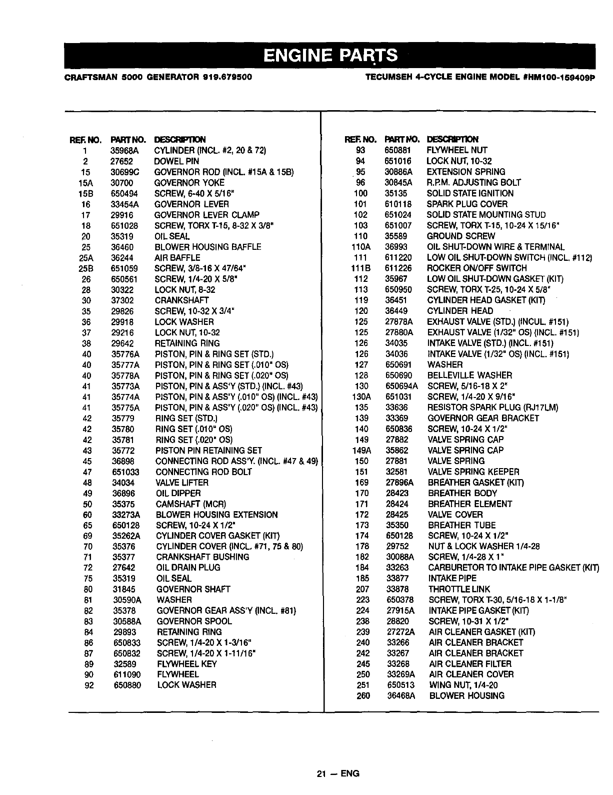
CRAFTSMAN 5000 GENERATOR 919,679500 TECUMSEH 4-CYCLE ENGINE MODEL #HM100-159409P
65
.o +
714 41
8_ 30 150_.151/" _149150 < 342
89 _"'151
70 1 '_'_325
6g
95
96
184 <_
72 I
II
182
101
25 /20
26
I
275 1
276 ' 112
/l 238 111
38O
178 r"_' 3
239
240 /.250
245
29O
370G
370L
/
t_/261282
281 \_
262 .. 260
J
285 370K
20 -- ENG
CRAFTSMAN 5000 GENERATOR 910.679500 TECUMSEH 4-CYCLE ENGINE MODEL #HM100-159409P
REKNO.
1 35968A
2 27652
15 30699C
15A 30700
15B 650494
16 33454A
17 29916
18 651028
20 35319
25 36460
25A 36244
25B 651059
26 650561
28 30322
30 37302
35 29826
36 29918
37 29216
38 29642
40 36776A
40 35777A
40 35778A
41 35773A
41 35774A
41 35775A
42 35779
42 35780
42 35781
43 35772
45 36898
47 651033
48 34034
49 36896
50 35375
60 33273A
65 650128
69 35262A
70 35376
71 35377
72 27642
75 35319
80 31845
81 30590A
92 35378
83 30588A
84 29893
86 650833
87 650832
89 52589
90 611090
92 650880
PARt'NO. m
CYLINDER (INCL. #2, 20 & 72)
DOWEL PIN
GOVERNOR ROD (INCL. #15A & 1513)
GOVERNOR YOKE
SCREW,6-40 X 5/16"
GOVERNOR LEVER
GOVERNOR LEVER CLAMP
SCREW,TORX T-15, 8-32 X 3/8"
OIL SEAL
BLOWER HOUSING BAFFLE
AIR BAFFLE
SCREW, 3/8-16 X 47/64"
SCREW, 1/4-20 X 5/8"
LOCK NUT,8-32
CRANKSHAFT
SCREW, 10-32 X 3/4"
LOCK WASHER
LOCK NUT, 10-32
RETAININGRING
PISTON, PIN &RING SET (STD.)
PISTON, PIN & RING SET (.910" OS)
PISTON, PIN & RING SET (.020" OS)
PISTON, PIN &ASS'Y (STD.) (INCL. #43)
PISTON, PIN &ABS'Y(.010" OS) (INCL. #43)
PISTON, PIN & ASS'Y (.020" OS) (INCL. #43)
RING SET (STD.)
RING SET (.010"OS)
RING SET (.020" OS)
PISTON PIN RETAININGSET
CONNECTING ROD ASS'tY. (INCL. #47 & 49)
CONNECTING ROD BOLT
VALVELIFTER
OIL DIPPER
CAMSHAFT (MCR)
BLOWER HOUSING EXTENSION
SCREW,10-24 X 1/2"
CYLINDERCOVER GASKET (KIT)
CYLINDER COVER (INCL, #71, 75 & 80)
CRANKSHAFT BUSHING
OIL DRAIN PLUG
OILSEAL
GOVERNOR SHAFT
WASHER
GOVERNOR GEARASS'Y (INCL. #61)
GOVERNOR SPOOL
RETAININGRING
SCREW,1/4-20 X 1-3/16"
SCREW, 1/4-20 X 1-11/16"
FLYWHEELKEY
FLYWHEEL
LOCK WASHER
RERNO.
93
94
95
96
100
101
102
103
110
110A
111
111B
112
113
119
120
125
125
126
128
127
126
130
130A
135
139
140
149
149A
150
151
169
170
171
172
173
174
178
182
184
185
2O7
223
224
238
239
240
242
245
25O
251
26O
PARTt,!=O.
650881
651016
30886A
30845A
35135
610118
651024
651007
35589
36993
611220
611226
35967
650950
36451
36449
27878A
27880A
34035
34036
650691
650690
650694A
651031
33636
33369
650836
27882
35862
27881
32581
27896A
28423
28424
28425
35350
650128
29752
30088A
33263
33877
33878
650378
27915A
28820
27272A
33266
33267
33266
33269A
65O513
36468A
DESCRIPTION
FLYWHEELNUT
LOCK NUT,10-32
EXTENSION SPRING
R.RM. ADJUSTING BOLT
SOLID STATEIGNITION
SPARK PLUG COVER
SOLID STATEMOUNTING STUD
SCREW,TORX T-15, 10-24 X 15/16"
GROUND SCREW
OIL SHUT-DOWN WIRE & TERMINAL
LOW OIL SHUT-DOWN SWITCH (INCL. #112)
ROCKER ON/OFF SWITCH
LOW OIL SHUT-DOWN GASKET(KIT)
SCREW,TORX T-25, 10-24 X 518"
CYLINDER HEAD GASKET(KIT)
CYLINDER HEAD
EXHAUST VALVE(STD.) (INCUL. #151)
EXHAUSTVALVE (1/32" OS) (INCL. #151)
INTAKEVALVE (STD.) (INCL.#151)
INTAKEVALVE(1/32" OS)(INCL. #151)
WASHER
BELLEVILLE WASHER
SCREW,5/16-18 X 2"
SCREW, 1/4-20 X 9/16"
RESISTORSPARKPLUG (RJ17LM)
GOVERNOR GEAR BRACKET
SCREW,10-24 X 1/2"
VALVESPRING CAP
VALVESPRING CAP
VALVESPRING
VALVESPRING KEEPER
BREATHER GASKET (KIT)
BREATHER BODY
BREATHER ELEMENT
VALVECOVER
BREATHER TUBE
SCREW,10-24 X 1/2"
NUT & LOCK WASHER 1/4-28
SCREW, 1/4-28 X 1•
CARBURETOR TO INTAKEPIPE GASKET(KIT)
INTAKEPIPE
THROTFLE LINK
SCREW,TORX T-30, 5/16-18 X 1-1/8"
INTAKEPIPEGASKET (KIT)
SCREW,10-31 X 1/2"
AIR CLEANER GASKET (KIT)
AIR CLEANER BRACKET
AIR CLEANER BRACKET
AIR CLEANER FILTER
AIR CLEANER COVER
WING NUT, 114-20
BLOWER HOUSING
21 -- ENG
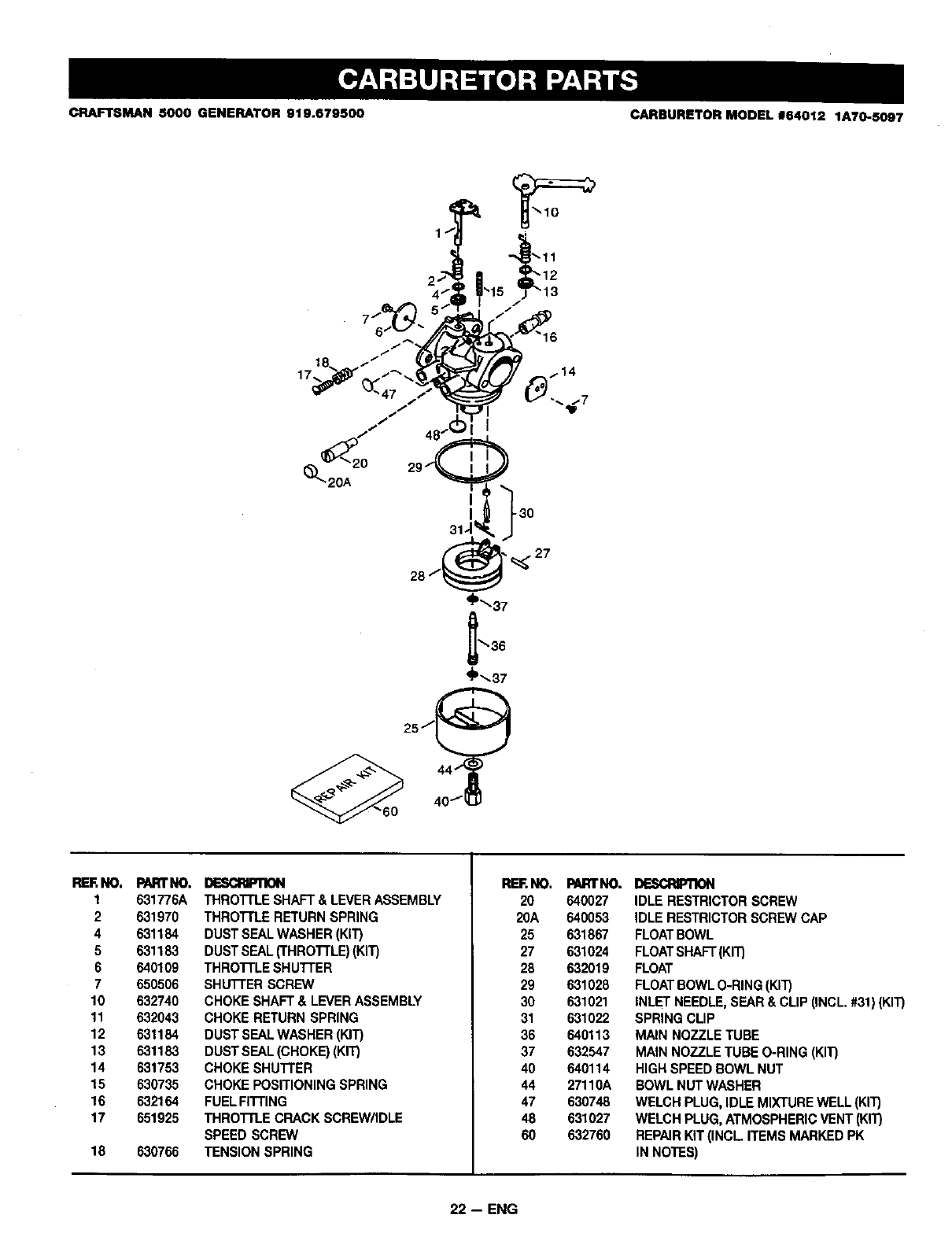
CRAFTSMAN 5000 GENERATOR 919.679500 CARBURETOR MODEL 164012 1A70-5097
_'-37
')'--37
RERNO. PARt'NO.
1 631776A
2 631970
4 631184
5 631183
6 640109
7650506
10 632740
11 632043
12 831184
13 631183
14 631753
15 630735
16 632164
17 651925
18 63O7_
I_SCRIP'nON
THROTTLE SHAFT & LEVERASSEMBLY
THROTi"LERETURN SPRING
DUST SEALWASHER (KIT)
DUST SEAL(THROTTLE)(KIT)
THROTTLE SHU'FFER
SHUTrER SCREW
CHOKE SHAFT & LEVER ASSEMBLY
CHOKE RETURN SPRING
DUST SEAL WASHER (KIT)
DUSTSEAL (CHOKE)(KIT)
CHOKE SHUI'rER
CHOKE POSITIONING SPRING
FUELFITTING
THROTrI.E CRACK SCREW/IDLE
SPEED SCREW
TENSION SPRING
REF.NO.
20
20A
25
27
28
29
3O
31
36
37
40
44
47
48
6O
PARTNO.
640027
640053
631867
631024
632019
631028
631021
631022
640113
632547
640114
27110A
630748
631027
632760
DESCRIPllON
IDLE RESTRICTORSCREW
IDLE RESTRICTOR SCREW CAP
FLOATBOWL
FLOATSHAFT(KIT)
FLOAT
FLOATBOWLO-RING (KIT)
INLET NEEDLE, SEAR& CLIP (INCL. #31) (KIT)
SPRING CLIP
MAIN NOZZLE TUBE
MAIN NOZZLE TUBE O-RING (KIT)
HIGH SPEED BOWL NUT
BOWL NUT WASHER
WELCH PLUG, IDLE MIXTUREWELL (KIT)
WELCH PLUG, ATMOSPHERICVENT (KIT)
REPAIRKIT (INCL. ITEMS MARKED PK
IN NOTES)
22 -- ENG
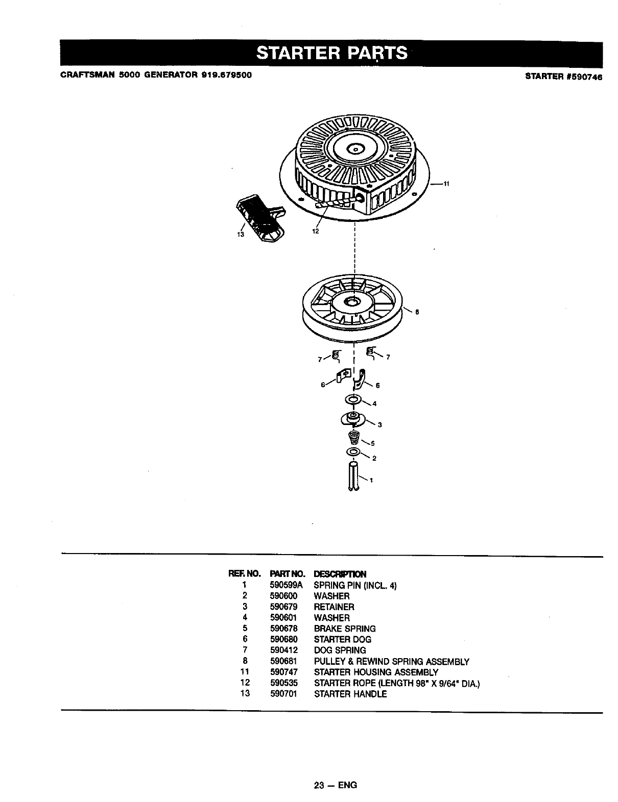
CRAFTSMAN 6000 GENERATOR 919.679500 STARTER #590746
13 12
_'8
REF.NO.
1
2
3
4
5
6
7
8
11
12
13
PARTNO.
590599A
5_6_
_79
590601
590678
5_6_
590412
590681
590_7
590535
_0701
DESCRIPTION
SPRING PIN (INCL 4)
WASHER
RETAINER
WASHER
BRAKE SPRING
STARTERDOG
DOG SPRING
PULLEY & REWIND SPRING ASSEMBLY
STARTERHOUSING ASSEMBLY
STARTERROPE (LENGTH 98" X 9/64" DIA.)
STARTERHANDLE
23 -- ENG
CALIFORNIA & US EPA EMISSION CONTROL WARRANTY STATEMENT
The U. S. Environmental Protection Agency ('EPA"), the California Air Resources Board ("CARB') and Tecumseh Products Co.
are pleased to explain the Federal and Califomia Emission Control Systems Warranty on your new utility or lawn and garden
equipment engine. In California, new 1995 and later utility and lawn and garden equipment engines must be designed, builtand
equipped to meet the State's stringent anti-smog standards, in other states, new 1997 and later model year engines must be
designed, built and equipped, at the time of sale, to meet the U.S. EPA regulations for small non-road engines. Tecumseh
Products Co. will warrant the emission control system on your utility or lawn and garden equipment engine for the periods of time
listed below, provided there has been no abuse, neglect, unapproved modification, or improper maintenance of your utility or lawn
and garden equipment engine.
Your emission control system may incJudeparts such as the carburetor, ignition system and exhaust system. Also included may
be the compression release system and other emission-related assemblies.
Where a warrantable condition exists, Tecumseh Products Co. will repair your utility or lawn and garden equipment engine at no
cost to you for diagnosis, parts and labor.
MANUFACTURER'S EMISSION CONTROL SYSTEM WARRANTY COVERAGE
Emission control systems on 1995 and later model year California utility and lawn end garden equipment engines are warranted
for two years as hereinafter noted. In other states, 1997 and later model year engines are also warranted for two yearn. If, during
such warranty period, any emission-related part on your engine is defective in materials or workmanship, the part will be repaired
or replaced by Tecumseh Products Co.
OWNER'S WARRANTY RESPONSIBILITIES
As the utility or lawn and garden equipment engine owner, you are responsible for the performance of the required maintenance
listed in your Owner's Manual, but Tecumseh Products Co. will not deny warranty solely due to the lack of receipts or for your
failure to provide written evidence of the performance of all scheduled maintenance.
As the utility or lawn and garden equipment engine owner, you should, however, be aware that Tecumseh Products Co. may
deny you warranty coverage if your utility or lawn and garden equipment or a part thereof has failed due to abuse, neglect,
improper maintenance or unapproved modifications.
You are responsible for presenting your utility or lawn and garden equipment engine to a Tecumseh Authorized Service Outlet
(any Tecumseh Registered Service Dealer, Tecumseh Authorized Service Distributor or Tecumseh Central Warehouse Distribu-
tor) as soon as a problem exists. The warranty repairs should be completed in a reasonable amount of time, not to exceed 30
days.
Warranty service can be arranged by contacting either a Tecumseh Authorized Service Outlet or by contacting Tecumseh
Products Co., PJoService Manager. Engine and Transmission Group Service Division. 900 North Street, Grefton, WI 53024-1499.
Telephone 1-414-377-2700, or see your local telephone yellow pages under =Engines, Gasoline" for the name, address and
telephone number of a Tecumseh Authorized Service Outlet near you.
IMPORTANT NOTE
This warranty statement explains your rights and obligations under the Emission Control System Warranty ('ECS Warranty')
which is provided to you by Tecumseh Products Co. pursuant to California law. Tecumseh Products Co. also provides to original
purchasers of new Tecumseh Products Co. engines, The Tecumseh Products Co. Limited Warranties for New Tecumseh Engine
end Electronic Ignition Modules ('Tecumseh Products Co. Warranty') which is enclosed with all new Tecumseh Products Co,
engines on a separate sheet. The ECS Warranty applies only to the emission control system of your new engine. To the extent
that there is any conflict in terms between the ECS Warranty and the Tecumseh Products Co, Warranty, the ECS Warranty shall
apply except in any circumstances in which the Tecumseh Products Co. Warranty may provide a longer warranty period. Both
the ECS Wenanty and the Tecumseh Products Co. Warranty describe important rights and obligations with respect to your new
engine.
Warranty service can only be performed by • Tecumseh Products Co. Autho_zed Service Outlet, or by Tecumseh Products Co.
at its factory in Grafton, WI. At the time of requesting warranty service, evidence must be presented of the date of sale to the
odginel purchaser. The purchaser shall pay any charges for making service calls and/or fo_ transporting the products to and from
the place where the iospec_n and/or warranty work is pedom_ed. The purchaser shall he responsible for any damage or loss
Incurred in comlec6_n with the transportation of any engine or any part(s) thereof submitted for inspection and/or warranty work.
If youhaveImy questionsregardingyourwarrantyrightsandresponsibilities,youshouldcontactTecomsehProductsCo. at
1-414-3772700.
24 -- ENG
EMISSION CONTROL SYSTEM WARRANTY
Emission Control System Warranty ('ECS Wananty') for 1995 end later model year Califomta utility and lawn and garden equip
ment engines (for other states, 1997 and later model year engines):
A. APPLICABILITY: This warranty shall apply to 1995 and later model year California utility and lawn and garden equipment
engines (for other states, 1997 and later model year engines1, The ECS Warranty Pedod shall begin on the date the now
engine or equipment is delivered to its original, end-use porcnaser, and shall continue for 24 consecutive months thereafter.
B, GENERAL EMISSIONS WARRANTY COVERAGE: Tecumseh Products Co. warrants to the original, end-use purchaser of
the new engine or equipment and to each subsequent purchaser that each of its utilityand lawn and garden equipment
engines is:
1. Designed, built and equipped so as to conform with all applicable regulations adopted by the Air Resources Board pursuant
to its authodty in Chapters 1 and 2, Part 5, Division 26 of the Health and Safety Code, and
2. Free from defects in materials and workmanship which, at any time during the ECS Warranty Period, will cause a warranted
emissions-related part to fail to be identical in all material respects to the part as described in the engine manufacturer's
application for certification.
C. The ECS Warranty only pertains to emissions-related paris on your engine, as follows:
1. Any warranted, emissions-related parts which are not scheduled for replacement as required maintenance in the Owner's
Manual shall be warranted for the ECS Warranty Padnd. If any such part fails during the ECS Warranty Pedod, it shall be
repaired or replaced by Tecumseh Products Co. according to Subsection 4 below. Any such part repa=rodor replaced
under the ECS Warranty shall be warranted for any remainder of the ECS Warranty Pedod.
2. Any warranted, emissions-related part which is scheduled only for regular inspection as specified in the Owner's Manual
shall be warranted for the ECS Warranty Period. A statement in such written instructions to the effect of =repairor replace
as necessary', shall not reduce the ECS Warranty Period. Any such part repaired or replaced under the ECS Warranty
shall be warranted for the remainder of the ECS Warranty Period.
3. Any warranted, emissions-related part which is scheduled for replacement as required maintenance in the Owner's Manual,
shall be warranted for the pedod of time prior to the first scheduled replacement point for that part. If the part fails prior to
the first scheduled replacement, the part shall be repaired or replaced by Tecumseh Products Co. according to Subsection
4 below. Any such emissions-related part repaired or replaced under the ECS Warranty, shall be warranted for the remain-
der of the ECS Warranty Pedod prior to the first scheduled replacement point for such emissions-related part.
4. Repair or replacement of any warranted, emissions-related part under this ECS Warranty shall be performed at no charge to
the Owner at-a Tecumseh Au'f66-r_edS_rt, ice Outlet. - "
5. The owner shall not be charged for diagnostic labor which leads to the determination that a part covered by the ECS
Warranty is in fact defective, provided that such diagnostic work is performed at a Tecumseh Authorized Service Outlet.
6. Tecumseh Products Co. shall be liable for damages to other odginal engine components or approved modifications proxi-
mately caused by a failure under warranty of an emission-related part covered by the ECS Warranty.
7. Throughout the ECS Warranty Period, Tecumseh Products Co. shall maintain a supply of warranted emission-related parts
sufficient to meet the expected demand for such emission-related parts.
8. Any Tecumseh Products Co. authorized and approved emission-related replacement part may be used in the performance
of any ECS Warranty maintenance or repair and will be provided without charge to the owner. Such use shall not reduce
Tecumseh Products Co. ECS Warranty obligations.
9. Unapproved add-on or modified parts may not be used to modify or repair a Tecumseh Products Co. engine. Such use
voids this ECS Warranty and shall be sufficient grounds for disallowing an ECS Warranty claim. Tecumseh Products Co.
shall not be liable hereunder for failures of any warranted parts of a Tecumseh Products Co. engine caused by the use of
such an unapproved add-on or modified part.
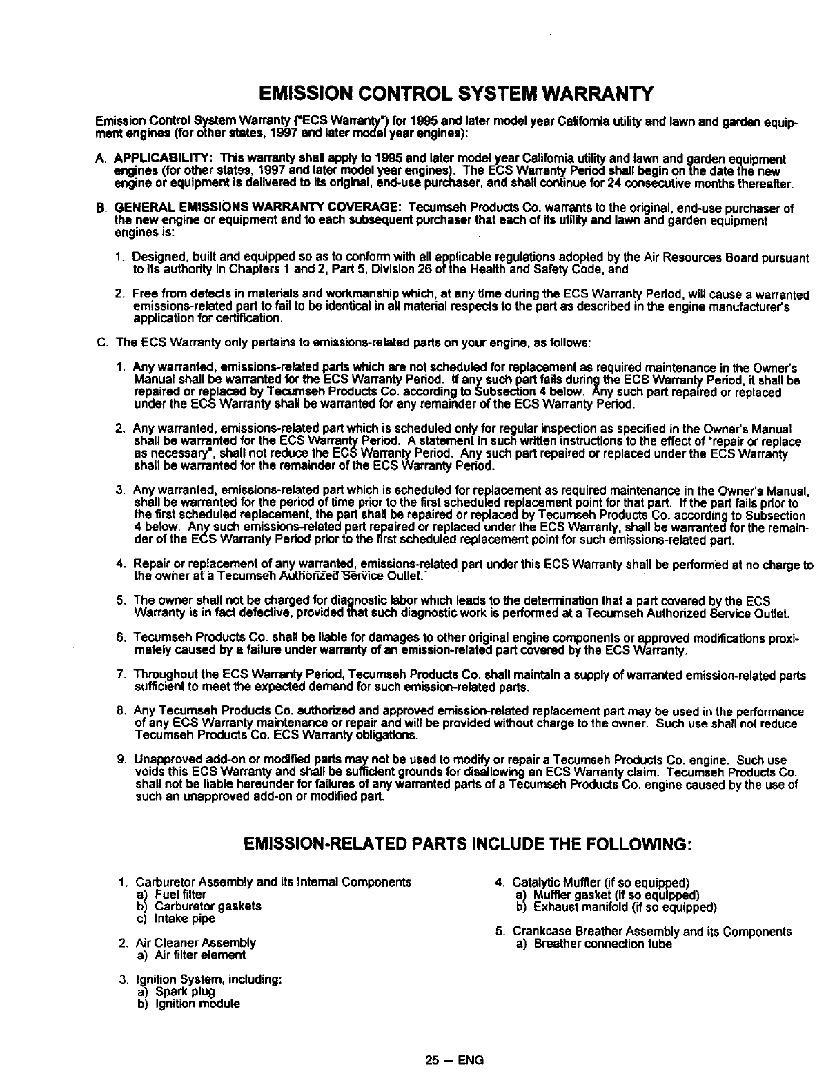
EMISSION-RELATED PARTS INCLUDE THE FOLLOWING:
1. Carburetor Assembly and its Internal Components
a) Fuel filter
b) Carburetor gaskets
c) Intake pipe
2. Air Cleaner Assembly
a) Air filter element
3. Ignition System, including:
a) Spark plug
b) Ignition module
4. Catalytic Muffler (if so equipped)
a) Muffler gasket (if so equipped)
b) Exhaust manifold (if so equipped)
5. Crankcase Breather Assembly and its Components
a) Breather connection tube
25 -- ENG
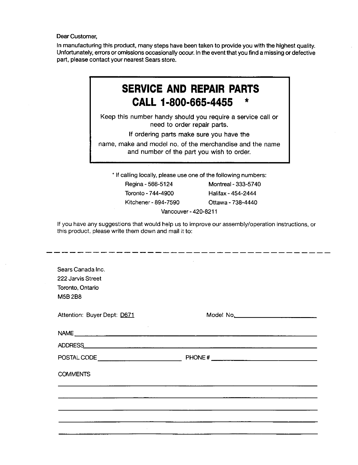
Dear Customer,
In manufacturing this product, many steps have been taken to provide you with the highest quality.
Unfortunately, errors or omissions occasionally occur. In the event that you find a missing or defective
part, please contact your nearest Sears store.
SERVICEAND REPAIRPARTS
CALL1-800-665-4455 *
Keep this number handy should you require a service call or
need to order repair parts.
If ordering parts make sure you have the
name, make and model no. of the merchandise and the name
and number of the part you wish to order.
* If calling locally, please use one of the following numbers:
Regina - 566-5124 Montreal - 333-5740
Toronto - 744-4900 Halifax - 454-2444
Kitchener - 894-7590 Ottawa - 738-4440
Vancouver - 420-8211
If you have any suggestions that would help us to improve our assembly/operation instructions, or
this product, please write them down and mail it to:
Sears Canada Inc.
222 Jarvis Street
Toronto, Ontario
MSB 2B8
Attention: Buyer Dept: D671
NAME
ADDRESS
POSTAL CODE
Model No.
PHONE #
COMMENTS
