Craftsman 921165720 User Manual AIR COMPRESSOR Manuals And Guides 1307137L
User Manual: Craftsman 921165720 921165720 CRAFTSMAN AIR COMPRESSOR - Manuals and Guides View the owners manual for your CRAFTSMAN AIR COMPRESSOR #921165720. Home:Tool Parts:Craftsman Parts:Craftsman AIR COMPRESSOR Manual
Open the PDF directly: View PDF ![]() .
.
Page Count: 45
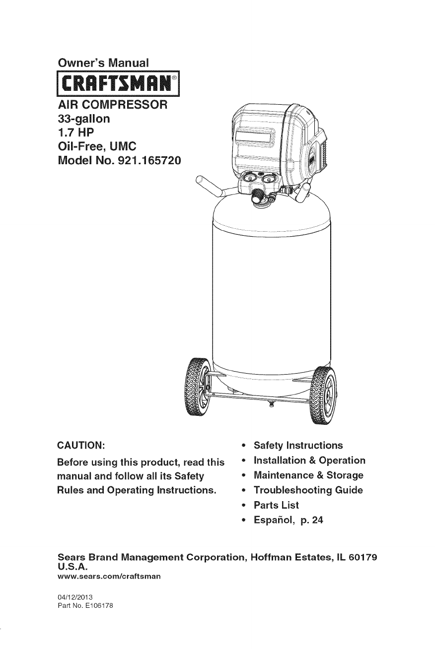
Owner's Manual
icR. M..i
AiR COMPRESSOR
33-gallon
1.7 HP
Oil-Free, UMC
Model No. 921.165720
CAUTION:
Before using this product, read this
manual and follow all its Safety
Rules and Operating instructions.
•Safety instructions
•Installation & Operation
•Maintenance &Storage
•Troubleshooting Guide
• Parts List
•EspaSol, p. 24
Sears Brand Management Corporation, Hoffman Estates, IL 60179
U.S.A.
www.sears.com/craftsman
04/12/2013
Part No. E106178
Page
Warranty .......................................... see below
Safety Symbols ............................................ 3
Important Safety Instructions & Guidelines ....................... 3
Specifications ............................................. 9
Glossary ................................................. 9
Duty Cycle ............................................... 10
Overview ................................................ 11
Assembly ................................................ 12
Installation ............................................ 13-14
Operating Procedures ...................................... 15
Maintenance ............................................. 16
Storage ................................................. 16
Troubleshooting Guide .................................. 17-18
Parts List ............................................. 19-21
Spanish ................................................. 24
Service Number .................................... back cover
ONE YEAR FULL WARRANTY ON CRAFTSMAN
AIR COMPRESSOR
If this Craftsman Air Compressor fails due to manufacturer's defects
in material or workmanship within one year of the date of purchase,
RETURN IT TO THE NEAREST SEARS STORE OR SERVICE CENTER IN
THE UNITED STATES and it will be replaced or repaired (at our option),
free of charge.
If this Air Compressor is used for commercial or rental purposes, this
warranty applies for only 90 days from the date of purchase. This warranty
gives you specific legal rights and you may also have other rights which
vary from state to state.
Sears Brand Management Corporation, Hoffman Estates, IL 60179
U.S.A.
2- ENG
This manual contains information that is important for you to know and understand.
This information relates to protecting YOUR SAFETY and PREVENTING
EQUIPMENT PROBLEMS. To help you recognize this information, we use the
symbols below. Please read the manual and pay attention to these symbols.
Indicates an imminently
hazardous situation which, if not
avoided, will result in death or serious
injury.
Indicates a potentially
hazardous situation which, if not
avoided, could result in death or
serious injury.
Indicates a potentially
hazardous situation which, if not
avoided, may result in minor or
moderate injury.
Indicates a practice
not related to personal injury which,
if not avoided, may result in property
damage.
_This product contains chemicals known to the State of California
to cause cancer, and birth defects or other reproductive harm. Wash hands after
handling.
_Some dust contains chemicals known to the State of California
to cause cancer, birth defects or other reproductive harm such as asbestos and
lead in lead based paint.
To reduce the risk of injury, read the instruction manual._\__J
SAVE THESE INSTRUCTIONS
RISK OF EXPLOSION OR FIRE
WHAT CAN HAPPEN HOW TO PREVENT IT
= Itis norma! f0r e!ectdca! e Always operate the compressor
Contacts within the motor and in a well ventilated area free
piessure Switch to spark. , CombuStible materials,
gasoline, or solvent vapors.
• If electrical sparks from • If spraying flammable materials,
compressor come into contact locate compressor at least
with flammable vapors, they may 20' (6.1 m) away from spray
ignite, causing fire or explosion, area. An additional length of
air hose may be required.
• Store flammable materials
in a secure location away
from compressor.
3- ENG
Restricting any of the com-
pressor ventilation openings
will cause serious overheat-
ing and could cause fire.
Unattended operation of this prod-
uct could result in personal injury
or property damage. To reduce the
risk of fire, do not allow the com-
pressor to operate unattended.
'W
• Never place objects against
or on top of compressor.
• Operate compressor in an open
area at least 12" (30.5 cm) away
from any wall or obstruction that
would restrict the flow of fresh
air to the ventilation openings.
e Operate compressor in a
clean, dry well ventilated area.
Do not operate unit in any
confined area. Store indoors.
• Always remain in attendance with
the product when it is operating.
Always turn off and unplug
unit when not in use.
__ RISK TO BREATHING (ASPHYXIATION)
WHAT CAN HAPPEN
*The compressed air directly from
your compressor is not safe
breathing, The ai[ stream may
contain carbon monoxide, toxic
vapors, 0r solid particles from the air
tank. Breathing these c0ntaminants
can cause serious injury or death:
Exposure to chemicals in dust
created by power sanding,
sawing, grinding, drilling,
and other construction
activities may be harmful.
Sprayed materials such as paint,
paint solvents, paint remover,
insecticides, weed killers, may
contain harmful vapors and poisons.
HOW TO PREVENT IT
•Never use air obtained directly
from the compress0r t0 supply
air for human consumption. The
compressor is not equipped with
suitable filters and in.line safety
equipment for human consumption.
Work in an area with good cross
ventilation. Read and follow
the safety instructions provided
on the label or safety data
sheets for the materials you are
spraying. Always use certified
safety equipment: NIOSH/OSHA
respiratory protection or properly
fitting face mask designed for use
with our s ecific a lication.
4- ENG
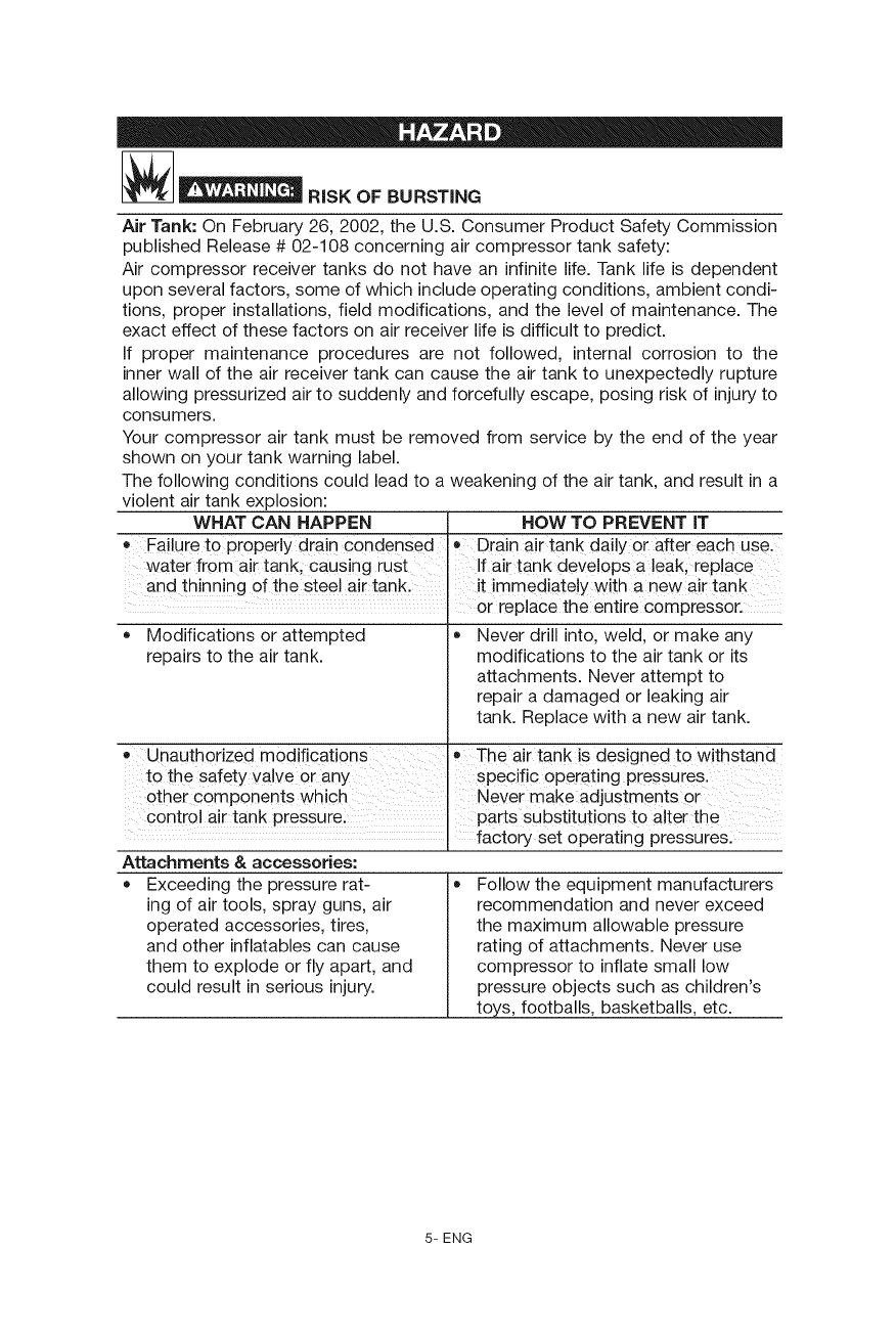
I_ IR_r_ RISK OF BURSTING
Air Tank: On February 26, 2002, the U.S. Consumer Product Safety Commission
published Release # 02-108 concerning air compressor tank safety:
Air compressor receiver tanks do not have an infinite life. Tank life is dependent
upon several factors, some of which include operating conditions, ambient condi-
tions, proper installations, field modifications, and the level of maintenance. The
exact effect of these factors on air receiver life is difficult to predict.
If proper maintenance procedures are not followed, internal corrosion to the
inner wall of the air receiver tank can cause the air tank to unexpectedly rupture
allowing pressurized air to suddenly and forcefully escape, posing risk of injury to
consumers.
Your compressor air tank must be removed from service by the end of the year
shown on your tank warning label.
The following conditions could lead to a weakening of the air tank, and result in a
violent air tank explosion:
WHAT CAN HAPPEN HOW TO PREVENT IT
• Failure to properly dra!n condensed • Drain air tank daily Or after each use.
water from air tank, causing rust If air tank deve!ops a !eak, replace
and thinning of the Steel air tank, it immediate!y with a new air tank
or replace the entire compressor.
• Modifications or attempted
repairs to the air tank.
o Unauthorized m0difications
to the safety Valve or any
other components which
control air tank pressure.
and other inflatables can cause
them to explode or fly apart, and
could result in serious injury.
Never drill into, weld, or make any
modifications to the air tank or its
attachments. Never attempt to
repair a damaged or leaking air
tank. Replace with a new air tank.
e The air tank is designed to withstand
specific operating pressures.
Never make adjustments or
parts Substitutions to alter the
factory set operating pressures.
Attachments & accessories:
Exceeding the pressure rat-
ing of air tools, spray guns, air
operated accessories, tires,
Follow the equipment manufacturers
recommendation and never exceed
the maximum allowable pressure
rating of attachments. Never use
compressor to inflate small low
pressure objects such as children's
toys, footballs, basketballs, etc.
5- ENG
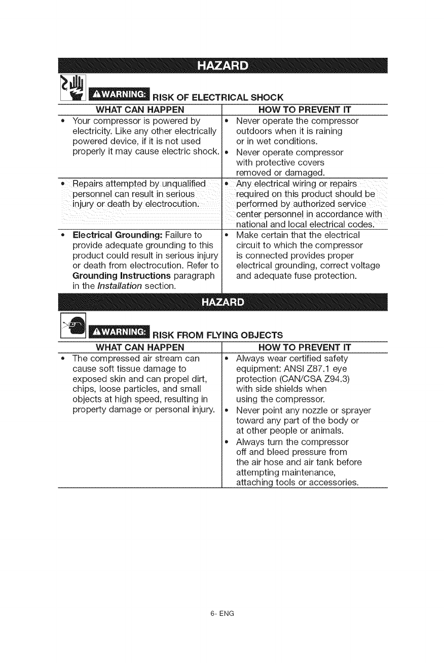
_-_ RiSK OF ELECTRICAL SHOCK
WHAT CAN HAPPEN
Your compressor is powered by
electricity. Like any other electrically
powered device, if it is not used
properly it may cause electric shock.
• Repairs attempted by unqualified
personnel Can result in serious
HOW TO PREVENT iT
• Never operate the compressor
outdoors when it is raining
or in wet conditions.
Never operate compressor
with protective covers
removed or damaged.
• Any electrical wiring or repa!rs
required on this product should be
injury or death by electrocution: performed by authorized service
' centei personne! in aCcordanCe with
national and local electrical code&
Electrical Grounding: Failure to
provide adequate grounding to this
product could result in serious injury
or death from electrocution. Refer to
Grounding instructions paragraph
in the Installation section.
Make certain that the electrical
circuit to which the compressor
is connected provides proper
electrical grounding, correct voltage
and adequate fuse protection.
__ RiSK FROM FLYING OBJECTS
HOW TO PREVENT iT
Always wear certified safety
equipment: ANSI Z87.1 eye
protection (CAN/CSA Z94.3)
with side shields when
using the compressor.
Never point any nozzle or sprayer
toward any part of the body or
at other people or animals.
Always turn the compressor
off and bleed pressure from
the air hose and air tank before
attempting maintenance,
attaching tools or accessories.
WHAT CAN HAPPEN
The compressed air stream can
cause soft tissue damage to
exposed skin and can propel dirt,
chips, loose particles, and small
objects at high speed, resulting in
property damage or personal injury.
6- ENG
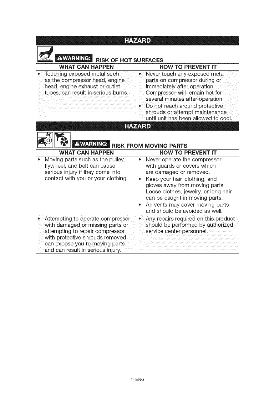
__ RiSK OF HOT SURFACES
WHAT CAN HAPPEN HOW TO PREVENT iT
•Touching exposed metal such Never touch any exposed metal
as the compresSor head, engine parts on compressor during or
head, engine exhaust or outlet immediately after operation.
tubes, can result in serious burns. Compressor wi!l remain hot for
several minutes after Operation.
,' D0n0t reach around protective
shrouds or attempt maintenance
until unit has been allowed to cool.
WHAT CAN HAPPEN
Moving parts such as the pulley,
flywheel, and belt can cause
serious injury if they come into
contact with you or your clothing.
0 Attempting to operate compressor
with damaged or missing parts or
attempting to repair compressor
with protective shrouds removed
can exPOSe you to moving parts
HOW TO PREVENT iT
• Never operate the compressor
with guards or covers which
are damaged or removed.
Keep your hair, clothing, and
gloves away from moving parts.
Loose clothes, jewelry, or long hair
can be caught in moving parts.
Air vents may cover moving parts
and should be avoided as well.
e Any repairs required on this product
should be performed by authorized
service center personnel.
and can result in serious injury.
7- ENG
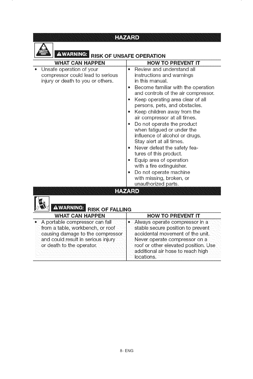
__ RiSK OF UNSAFE OPERATION
WHAT CAN HAPPEN HOW TO PREVENT iT
• Unsafe operation of your • Review and understand all
compressor could lead to serious instructions and warnings
injury or death to you or others, in this manual.
• Become familiar with the operation
and controls of the air compressor.
Keep operating area clear of all
persons, pets, and obstacles.
Keep children away from the
air compressor at all times.
Do not operate the product
when fatigued or under the
influence of alcohol or drugs.
Stay alert at all times.
Never defeat the safety fea-
tures of this product.
Equip area of operation
with a fire extinguisher.
Do not operate machine
with missing, broken, or
unauthorized parts.
__ RiSK OF FALLING
WHAT CAN HAPPEN HOW TO PREVENT IT
= Ap0rtable compressor can fa!Ie Always operate compressor in a
from a table, workbench, or roof stable secure position to prevent
causing damage to the c0mpress0r accidental movement of the un t.
and could result in serious injury Never operate compressor on a
Or death to the oPerator., roof or other e!evated Position. Use
additional air h0se tO reach high ....
locations:
8- ENG
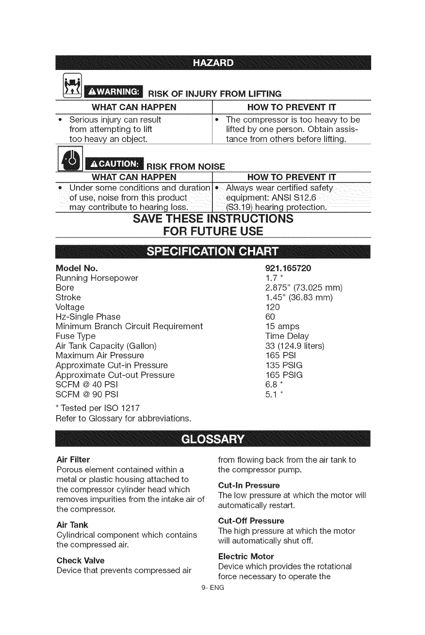
__ RiSK OF iNJURY FROM LiFTiNG
WHAT CAN HAPPEN HOW TO PREVENT iT
= Serious injurycan result = The compressor is too heavy to be
from attempting to lift lifted by one person. Obtain assis-
too heavy an object, tance from others before lifting.
RISK FROM NOISE
WHATCANHAPPEN I HOWTOPREVENTiT
• Under some conditions and durationlo Always wear Certified safety
of use; noise from this Pr0duct equipment: ANSI S12:6
may contribute to hearing loss: I (S3.19) hearing protection.
SAVE THESE INSTRUCTIONS
FOR FUTURE USE
Model No. 921.165720
Running Horsepower 1.7 *
Bore 2.875" (73.025 mm)
Stroke 1.45" (36.83 mm)
Voltage 120
Hz-Single Phase 60
Minimum Branch Circuit Requirement 15 amps
Fuse Type Time Delay
Air Tank Capacity (Gallon) 33 (124.9 liters)
Maximum Air Pressure 165 PSi
Approximate Cut-in Pressure 135 PSIG
Approximate Cut-out Pressure 165 PSIG
SCFM @ 40 PSi 6.8 *
SCFM @ 90 PSi 5.1 *
* Tested per ISO 1217
Refer to Glossary for abbreviations.
Air Filter
Porous element contained within a
metal or plastic housing attached to
the compressor cylinder head which
removes impurities from the intake air of
the compressor.
Air Tank
Cylindrical component which contains
the compressed air.
Check Valve
Device that prevents compressed air
from flowing back from the air tank to
the compressor pump.
Cut-In Pressure
The low pressure at which the motor will
automatically restart.
Cut-Off Pressure
The high pressure at which the motor
will automatically shut off.
Electric Motor
Device which provides the rotational
force necessary to operate the
9- ENG
compressor pump.
NPT (National Pipe Thread)
A seal thread tape must be used to
provide a leak-free seal on pipe threaded
connections.
Pressure Regulator Knob
Regulates the outgoing pressure from
the air outlet to the tool. It is possible to
increase or decrease the pressure at the
outlet by adjusting this control knob.
Pressure Switch
Automatically controls the on/off
cycling of the compressor. It stops the
compressor when the cut-off pressure
in the tank is reached and starts the
compressor when the air pressure drops
below the cut-in pressure.The pressure
switch will not automatically start and
control the compressor unless the
manual AUTO/Off Switch is in the
AUTO position.
PSI (Pounds Per Square inch)
Measurement of the pressure exerted
by the force of the air. The actual PSi is
measured by a pressure gauge on the
compressor.
Pump
Produces the compressed air with a
reciprocating piston contained within the
cylinder.
Regulator Pressure Gauge
Displays the current line pressure. Line
pressure is adjusted by rotating the
pressure regulator knob.
Pressure Relief Valve
Prevents air pressure in the air tank from
rising over a predetermined limit.
SCFM (Standard Cubic Feet Per Minute)
A unit of measure of air delivery.
Tank Pressure Gauge
indicates the pressure in the air tank.
Thermal Overload Switch
Automatically shuts off the compressor
ifthe temperature of the electric motor
exceeds a predetermined limit.
This air compressor pump is capable of running continuously. However, to prolong
the life of your air compressor, it is recommended that a 50%-75% average duty
cycle be maintained; that is,the air compressor pump should not run more than 30-
45 minutes in any given hour.
Accessories for this unit are available at the store the unit was purchased.
The use of any other accessory not recommended for use with this tool could
be hazardous. Use only accessories rated equal to or higher than the rating of
the air compressor.
10- ENG
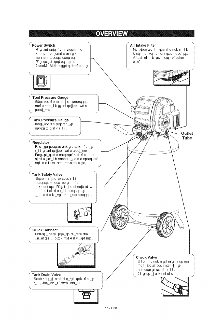
I PowerSwitch
Rf_qarrirp_qrfcnrrucprmrtc
knTrrpIbjqmrfcasrg-
asr-_rsrnl:cqqspcqcrrdleq,
I_$1qu_af qc_cq qrfc
?sr_l -Mddnrr(1_grriq dTprf c sl g_,
\
ITool Pressure Gauge
Sb_ rcq rf c rrsrerr_j e _n_qqspc
rmrfc rmi I b _tarri rl_jcb'wrf c
pcesj rr_
fTank Pressure Gauge
Sb_ rcqrfcFcqc#c _)
npcqqspc g rfcr li,
fAir Intake Filter /
NpTt_)cqajc I _rmrfcnskn Ib
k sqr_u vtq" c i cnr d;cc rrdbc" I:_J1,
Af cai rri b gw" q_q rrp" cdrpc
c af sqc,
I Regulator
Rfc g)npcqqspcarrkdle¢-rk rfc _)
r I i _qard rp_jcb" wrf c _esj rrr#
I_n_ a_ qc rfc n_qqs_*rs_ rf c i l n1
ajrrai u_c_l b rmbcapc qc rf c npcqqspc*
rsl3 rf c i I n1 arrsl rcpajrrai u _lc,
Tube
fTank Safety Valve
Sqcb rm jjrru cvacqq rl i
npcqqsl:c rmcqanc _ rmrf c
rk rnqnf cpc, Rf _1t _t c qf rrsjb rri jw
rrncl ufcl rfcrli npcqqspc$!
"_crfck v_sk _rcbnl:cqqspc,
I Quick Connect
M_l:q osffii pcjc qc _ rspc dTp
rr afdle Ibl:ckrrtdleffc g)frr(Ic,
\
/Tank Drain Valve
Sqcb rmb_ arri bcl cLrgh @Tk rf c
r li,Jrm rcb r'rrmrk r_r li,
r
Check Valve
Ufcl rfcnskn_l_ rmc_rg_
rf c t jt c ajrrqcq rmpcL_ _)
npcqqs_ _ q_c rf c r I i,
?1 _rcFi jarrknntclr,
11- ENG
ASSEMBLING THE COMPRESSOR
The air compressor should be turned off, unplugged from the power source, the
air bled from the tank and the unit allowed time to cool before any maintenance
is performed. Personal injuries could occur from moving parts, electrical sources,
compressed air or hot surfaces. The quick connect assembly must be attached
before use. Failure to assemble correctly could result in leaks and possible injury.
If unsure of assembly instructions or you experience difficulty in the assembly please
call your local service department for further information.
2.
3.
Unpack the air compressor. Inspect the unit for damage. If the unit has been
damaged in transit, contact the carrier and complete a damage claim. Do this i
mmediately because there are time limitations to damage claims.
Check the compressor's serial label to ensure that you have received the model
ordered, and that it has the required pressure rating for its intended use.
Locate the compressor according to the following guidelines:
a. Position the compressor near a grounded electrical outlet.
b. The compressor must be at least 12 inches (31 cm) from any wall or
obstruction, in a clean, well-ventilated area, to ensure sufficient air flow and
cooling.
c. In cold climates, store portable compressors in a heated building when
not in use. This will reduce problems with motor starting and freezing of
water condensation.
d. Remove the compressor from the carton and place it on the floor or a hard,
level surface. The compressor must be level to ensure proper drainage of
the moisture in the tank.
12- ENG
GETTING STARTED
Location of the Air Compressor
The air compressor should always be located in a clean, dry and well ventilated
environment. The unit should have at minimum, 12 inches of space on each side.
The air filter intake should be free of any debris or obstructions. Check the air filter
on a daily basis to make sure it is clean and in working order.
Risk Of Fire Or Explosion
This product incorporates snap action switch contacts and a universal electric
motor which tends to produce arcs and sparking and therefore should not
be exposed to flammable liquids or vapors. This product is not intended for
installation or use in a commercial garage or shop environment.
Grounding instructions
This product must be grounded. In the event of an electrical short circuit,
grounding reduces the risk of electric shock by providing an escape wire for the
electric current. This product is equipped with a cord having a grounding wire
with an appropriate grounding plug. (See Figure 3.) The plug must be plugged
into an outlet that is properly installed and grounded in accordance with all local
codes and ordinances. Check with a qualified electrician or service personnel if
these instructions are not completely understood or if in doubt as to whether the
tool is properly grounded.
Improper installation of the grounding plug will result
_ n a risk of electric shock. If repair or replacement
of the cord or plug is necessary, do not connect the
grounding wire to either flat blade terminal. The wire
with insulation having an outer surface that is green
with or without yellow stripes is the grounding wire. Check with a qualified
electrician or serviceman if the grounding instructions are not completely
understood, or if in doubt as to whether the product is properly grounded. Do
not modify the plug provided; if it will not fit the outlet, have the proper outlet
installed by a qualified electrician.
This product is for use on a nominal 120-V circuit and has a grounding plug
similar to the plug illustrated in (Figure 3). Only connect the product to an outlet
having the same configuration as the plug. Do not use an adapter with this
product.
13- ENG
GETTING STARTED
Extension Cords
Use only a 3-wire extension cord that has a 3-blade grounding plug, and a
3-slot receptacle that will accept the plug on the product. Make sure your
extension cord is in good condition. When using an extension cord, be sure to
use one heavy enough to carry the current your product will draw. Cords must
not exceed 50 feet and No. 12 AWG size must be used. An undersized cord will
cause a drop in line voltage resulting in loss of power and overheating.
Break In Procedures
No break in procedure is required by the user. This product is factory tested to
ensure proper operation and performance.
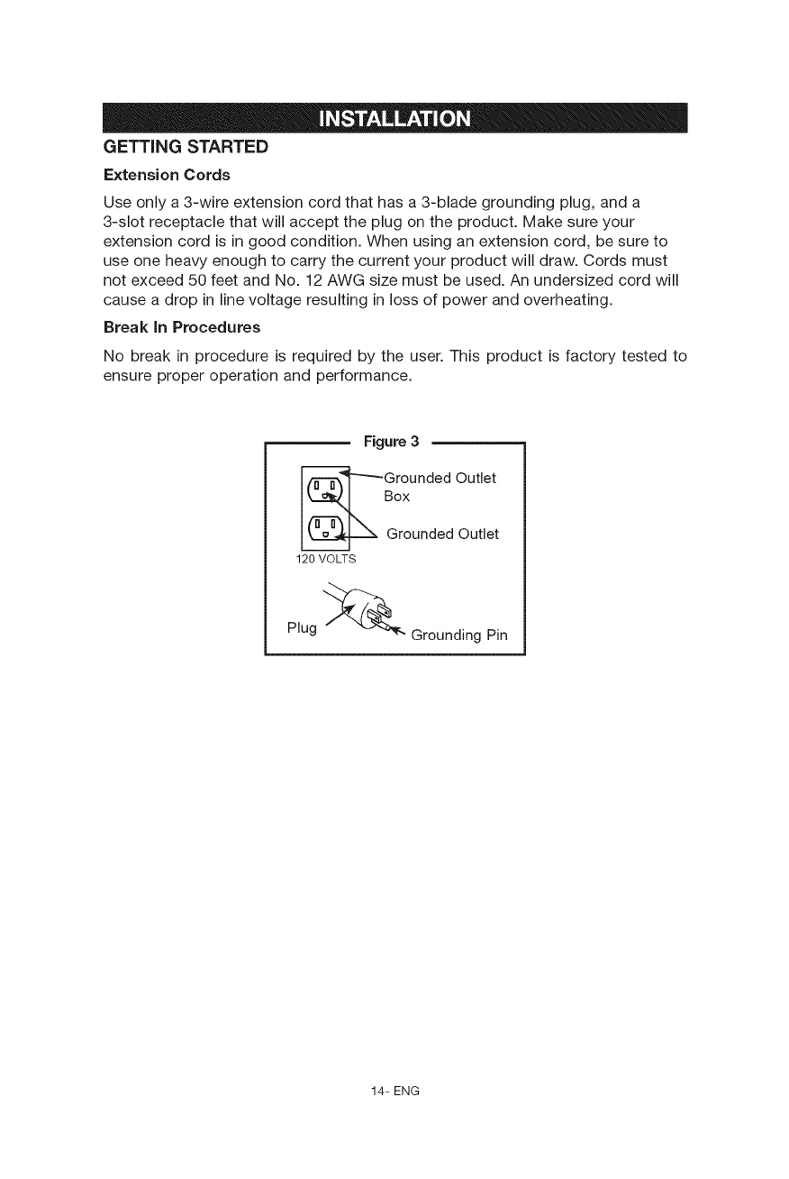
Figure 3
Grounded Outlet
Box
Grounded Out et
120 VOLTS
Plug _ Grounding Pin
14- ENG
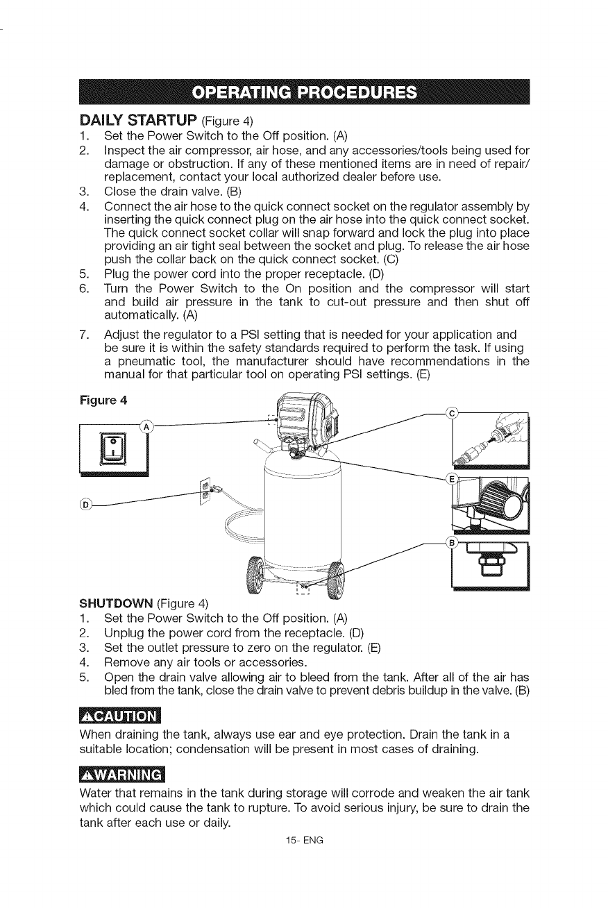
DAILY STARTUP (Figure4)
1. Set the Power Switch to the Off position. (A)
2. inspect the air compressor, air hose, and any accessories/tools being used for
damage or obstruction, if any of these mentioned items are in need of repair/
replacement, contact your local authorized dealer before use.
3. Close the drain valve. (B)
4. Connect the air hose to the quick connect socket on the regulator assembly by
inserting the quick connect plug on the air hose into the quick connect socket.
The quick connect socket collar will snap forward and lock the plug into place
providing an air tight seal between the socket and plug. To release the air hose
push the collar back on the quick connect socket. (C)
5. Plug the power cord into the proper receptacle. (D)
6. Turn the Power Switch to the On position and the compressor will start
and build air pressure in the tank to cut-out pressure and then shut off
automatically. (A)
7. Adjust the regulator to a PSI setting that is needed for your application and
be sure it is within the safety standards required to perform the task. If using
a pneumatic tool, the manufacturer should have recommendations in the
manual for that particular tool on operating PSI settings. (E)
Figure 4
SHUTDOWN (Figure 4)
1. Set the Power Switch to the Off position. (A)
2. Unplug the power cord from the receptacle. (D)
3. Set the outlet pressure to zero on the regulator. (E)
4. Remove any air tools or accessories.
5. Open the drain valve allowing air to bleed from the tank. After all of the air has
bled from the tank, close the drain valve to prevent debris buildup in the valve. (B)
When draining the tank, always use ear and eye protection. Drain the tank in a
suitable location; condensation will be present in most cases of draining.
Water that remains in the tank during storage will corrode and weaken the air tank
which could cause the tank to rupture. To avoid serious injury, be sure to drain the
tank after each use or daily.
15- ENG
To avoid personal injury, always shut off and unplug the
compressor and relieve all air pressure from the system before performing any
service on the air compressor.
To ensure efficient
operation and longer life of the
air compressor unit, a routine
maintenance schedule should be
followed. The following schedule is
geared toward a consumer whose
compressor is used in a normal
working environment on a daily basis.
This compressor is
items to Check/Change
Afcai Rli Q_rwT jtc
Mt cp jj Sl gfT_lsj Af cai
B_ Rli
Afcai NrrucpArr_odrpB k ec
Before each use
or daily
X
X
X
X
equipped with an automatic reset thermal overload protector which will shut off
motor if it becomes overheated, if the thermal overload protector is actuated, the
motor must be allowed to cool down before start-up is possible.
NOTE: The motor will automatically restart without warning if the unit is left
plugged in to an outlet with the Auto-On/Off switch in the on position.
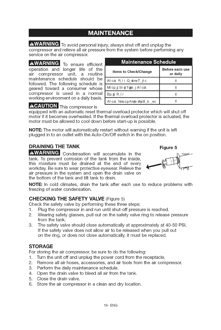
DRAINING THE TANK
Condensation will accumulate in the
tank. To prevent corrosion of the tank from the inside,
this moisture must be drained at the end of every
workday. Be sure to wear protective eyewear. Relieve the
air pressure in the system and open the drain valve on
the bottom of the tank and tilt tank to drain.
Figure 5
NOTE: In cold climates, drain the tank after each use to reduce problems with
freezing of water condensation.
CHECKING THE SAFETY VALVE (Figure 5)
Check the safety valve by performing these three steps:
1. Plug the compressor in and run until shut-off pressure is reached.
2. Wearing safety glasses, pull out on the safety valve ring to release pressure
from the tank.
3. The safety valve should close automatically at approximately at 40-50 PSi.
if the safety valve does not allow air to be released when you pull out
on the ring, or does not close automatically, it must be replaced.
STORAGE
For storing the air compressor, be sure to do the following:
1. Turn the unit off and unplug the power cord from the receptacle.
2. Remove all air hoses, accessories, and air tools from the air compressor.
3. Perform the daily maintenance schedule.
4. Open the drain valve to bleed all air from the tank.
5. Close the drain valve.
6. Store the air compressor in a clean and dry location.
16- ENG
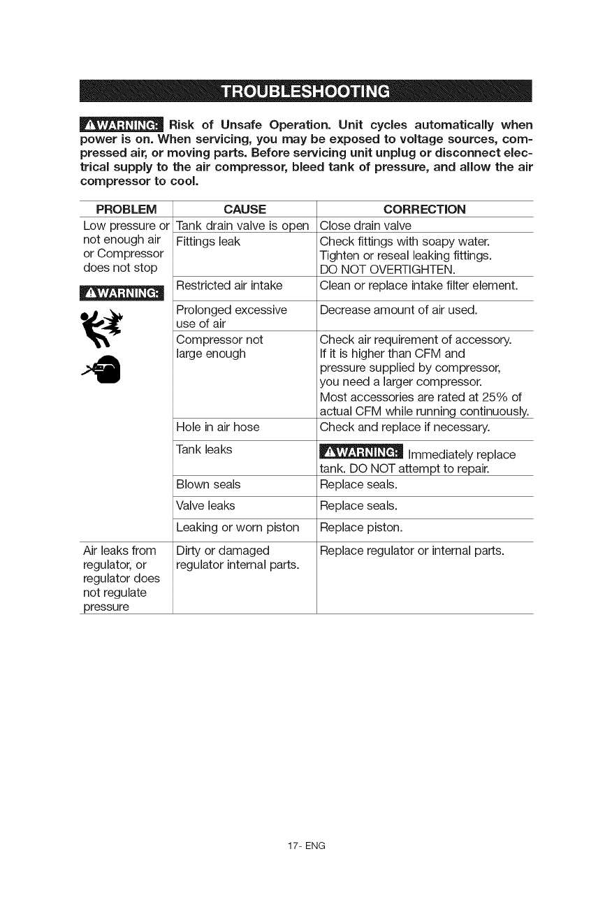
Risk of Unsafe Operation. Unit cycles automatically when
power is on. When servicing, you may be exposed to voltage sources, com-
pressed air, or moving parts. Before servicing unit unplug or disconnect elec-
trical supply to the air compressor, bleed tank of pressure, and allow the air
compressor to cool.
PROBLEM CAUSE CORRECTION
Low pressure or Tank drain valve is open Close drain valve
not enough air Fittings leak Check fittings with soapy water.
or Compressor Tighten or reseal leaking fittings.
does not stop DO NOT OVERTIGHTEN.
Restricted air intake Clean or replace intake filter element.
Decrease amount of air used.
Prolonged excessive
use of air
Compressor not
large enough
Hole in air hose
Tank leaks
Blown seals
Valve leaks
Leaking or worn piston Replace piston.
Air leaks from Dirty or damaged Replace regulator or internal parts.
regulator, or regulator internal parts.
regulator does
not regulate
pressure
Check air requirement of accessory.
If it is higher than CFM and
3ressure supplied by compressor,
/ou need a larger compressor.
Most accessories are rated at 25% of
actual CFM while running continuously.
Check and replace if necessary.
immediately replace
tank. DO NOT attempt to repair.
Replace seals.
Replace seals.
17- ENG
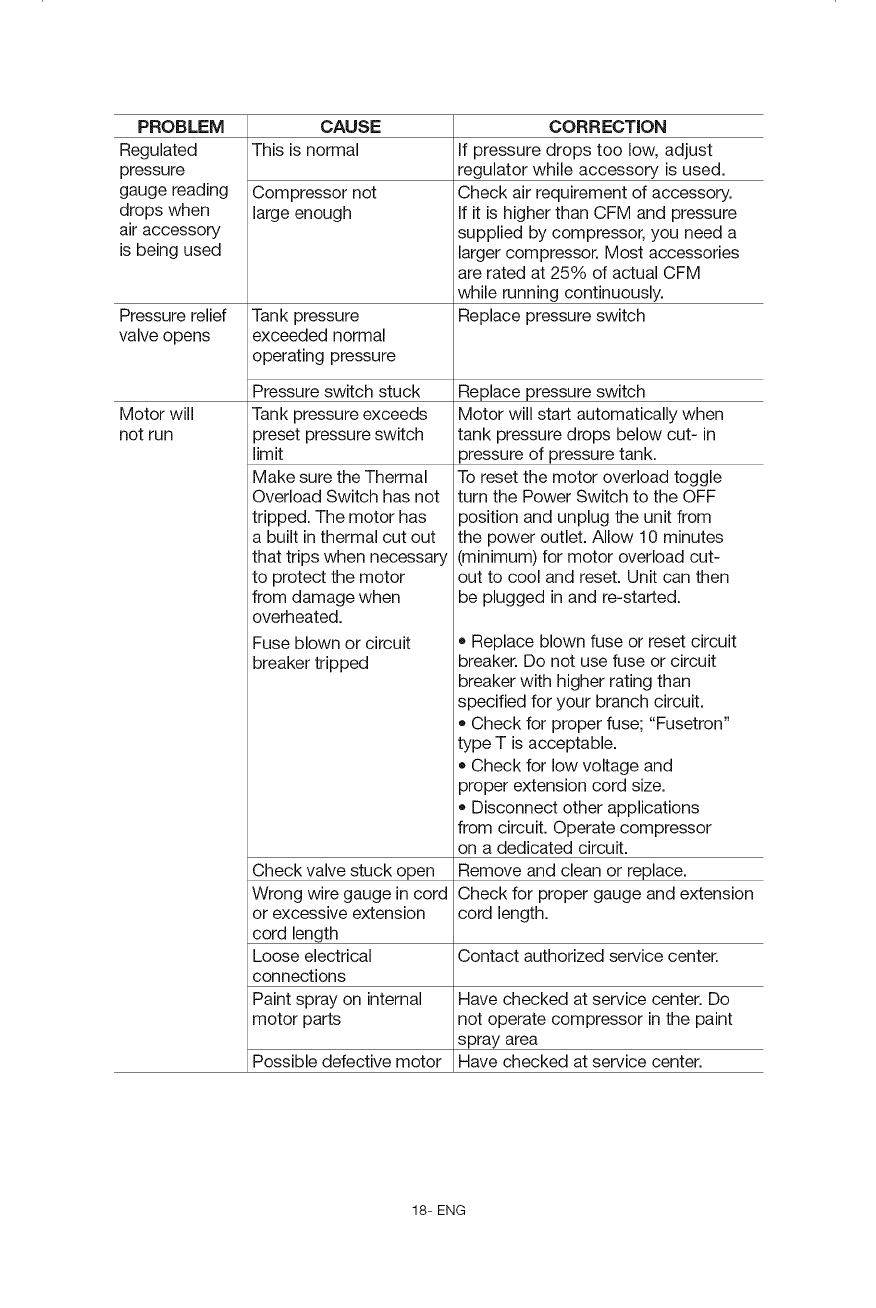
PROBLEM
Regulated
pressure
gauge reading
drops when
air accessow
is being used
CAUSE
This is normal
Compressor not
large enough
Pressure relief Tank pressure
valve opens exceeded normal
operating pressure
Pressure switch stuck
Motor will Tank pressure exceeds
not run preset pressure switch
limit
Make sure the Thermal
Overload Switch has not
tripped. The motor has
a built in thermal cut out
that trips when necessaw
to protect the motor
from damage when
overheated.
Fuse blown or circuit
breaker tripped
CORRECTION
If pressure drops too low, adjust
regulator while accessow is used.
Check air requirement of accessory.
If it is higher than CFM and pressure
supplied by compressor, you need a
larger compressor. Most accessories
are rated at 25% of actual CFM
while running continuously.
Replace pressure switch
Replace pressure switch
Motor will start automatically when
tank pressure drops below cut- in
3ressure of pressure tank.
To reset the motor overload toggle
turn the Power Switch to the OFF
3osition and unplug the unit from
the power outlet. Allow 10 minutes
(minimum) for motor overload cut-
out to cool and reset. Unit can then
be plugged in and re-started.
• Replace blown fuse or reset circuit
breaker. Do not use fuse or circuit
breaker with higher rating than
specified for your branch circuit.
Check for proper fuse; "Fusetron"
type T is acceptable.
Check for low voltage and
proper extension cord size.
Disconnect other applications
from circuit. Operate compressor
on a dedicated circuit.
Check valve stuck open Remove and clean or replace.
Wrong wire gauge in cord Check for proper gauge and extension
or excessive extension cord length.
cord length
Loose electrical Contact authorized service center.
connections
Paint spray on internal Have checked at service center. Do
motor parts not operate compressor in the paint
spray area
Possible defective motor Have checked at service center.
18- ENG
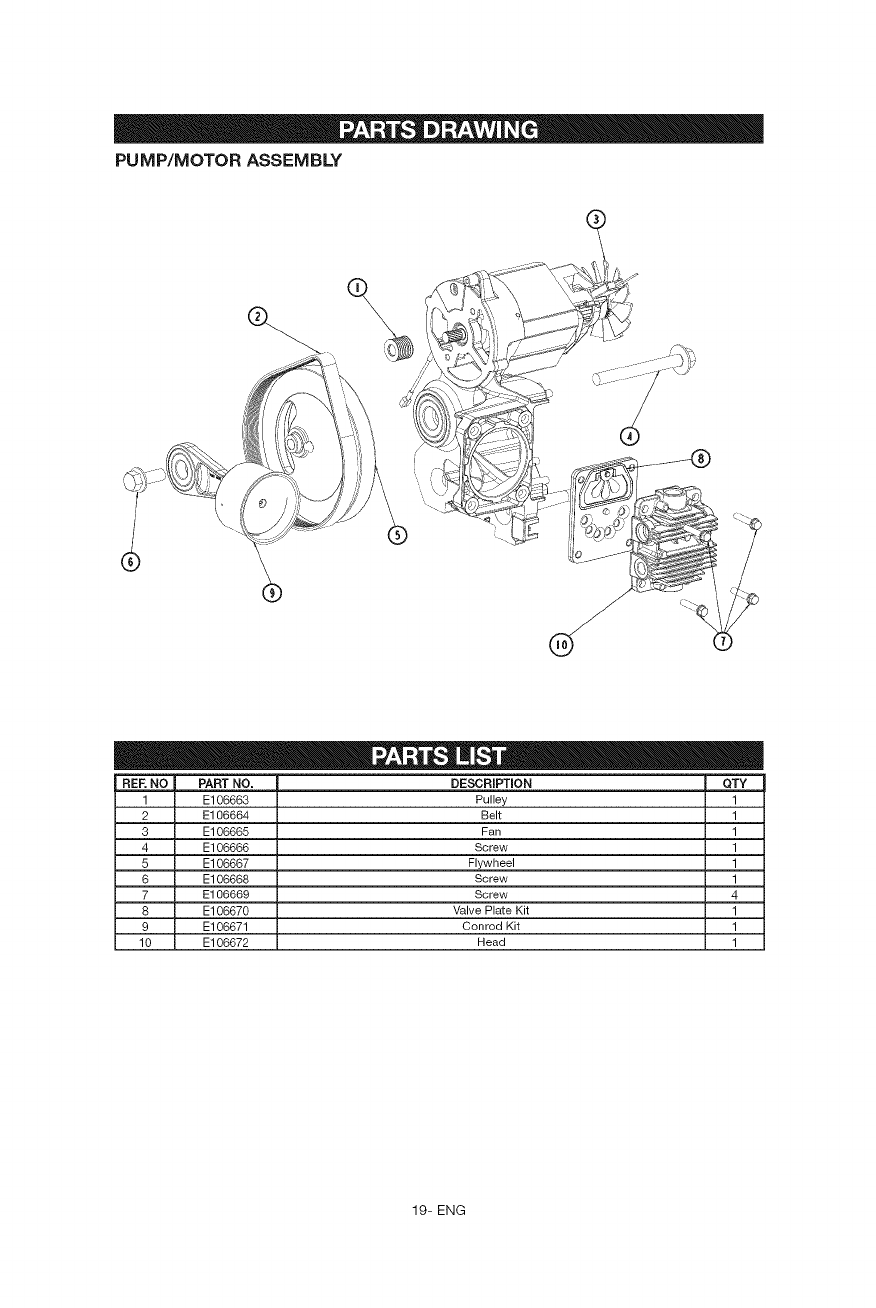
PUMP/MOTOR ASSEMBLY
%
/
d
®
REF, NO PART NO. DFSCRJPTJON QTY
1 E106663 Pulley 1
2 E106664 Belt 1
3 E106665 Fan 1
4 E106666 Screw 1
5 E106667 Flywheel 1
6 E106668 Screw 1
7 E106669 Screw 4
8 E106670 Valve Plate Kit 1
9 E106671 Conrod Kit 1
10 E106672 Head 1
19- ENG
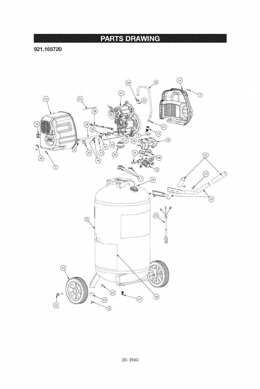
921.165720
• --oJ
20- ENG
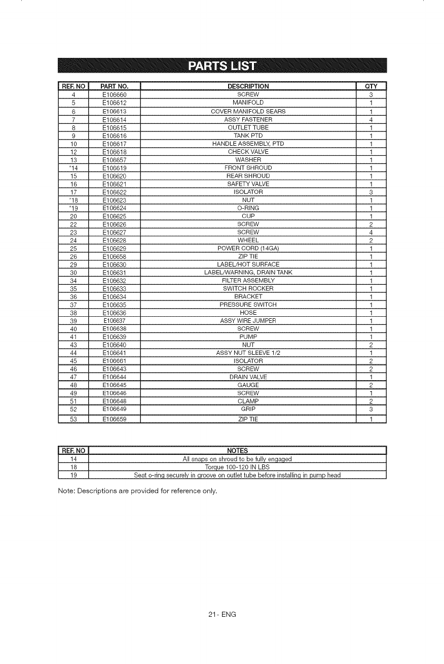
REE NO PART NO.
4 E106660
5 E106612
6 E106613
7 E106614
8 E106615
9 E106616
10 E106617
12 E106618
13 E106657
"14 E106619
15 E106620
16 E106621
17 E106622
"18 E106623
"19 E106624
20 E106625
22 E106626
23 E106627
24 E106628
25 E106629
26 E106658
29 E106630
30 E106631
34 E106632
35 E106633
36 E106634
37 E106635
38 E106636
39 E106637
40 E106638
41 E106639
43 E106640
44 E106641
45 E106661
46 E106643
47 E106644
48 E106645
49 E106646
51 E106648
52 E106649
53 E106659
DESCRIPTION QTY
SCREW 3
MANIFOLD 1
COVER MANIFOLD SEARS 1
ASSY FASTENER 4
OUTLET TUBE 1
TANK PTD 1
HANDLE ASSEMBLY, PTD 1
CHECK VALVE 1
WASHER 1
FRONT SHROUD 1
REAR SHROUD 1
SAFETY VALVE 1
ISOLATOR 3
NUT 1
O-RING 1
CUP 1
SCREW 2
SCREW 4
WHEEL 2
POWER CORD (14GA) 1
ZiP TIE 1
LABEL/HOT SURFACE 1
LABEL/WARNING, DRAIN TANK 1
FILTER ASSEMBLY 1
SWITCH ROCKER 1
BRACKET 1
PRESSURE SWITCH 1
HOSE 1
ASSY WIRE JUMPER 1
SCREW 1
PUMP 1
NUT 2
ASSY NUT SLEEVE 1/2 1
ISOLATOR 2
SCREW 2
DRAIN VALVE 1
GAUGE 2
SCREW 1
CLAMP 2
GRIP 3
ZiP TIE 1
REF.NO
14
18
19
NOTES
All snaps on shroud to be fully engaged
Torque 100-120 IN LBS
Seat o-ring securely in groove on outlet tube before installing in pump head
Note: Descriptions are provided for reference only.
21- ENG
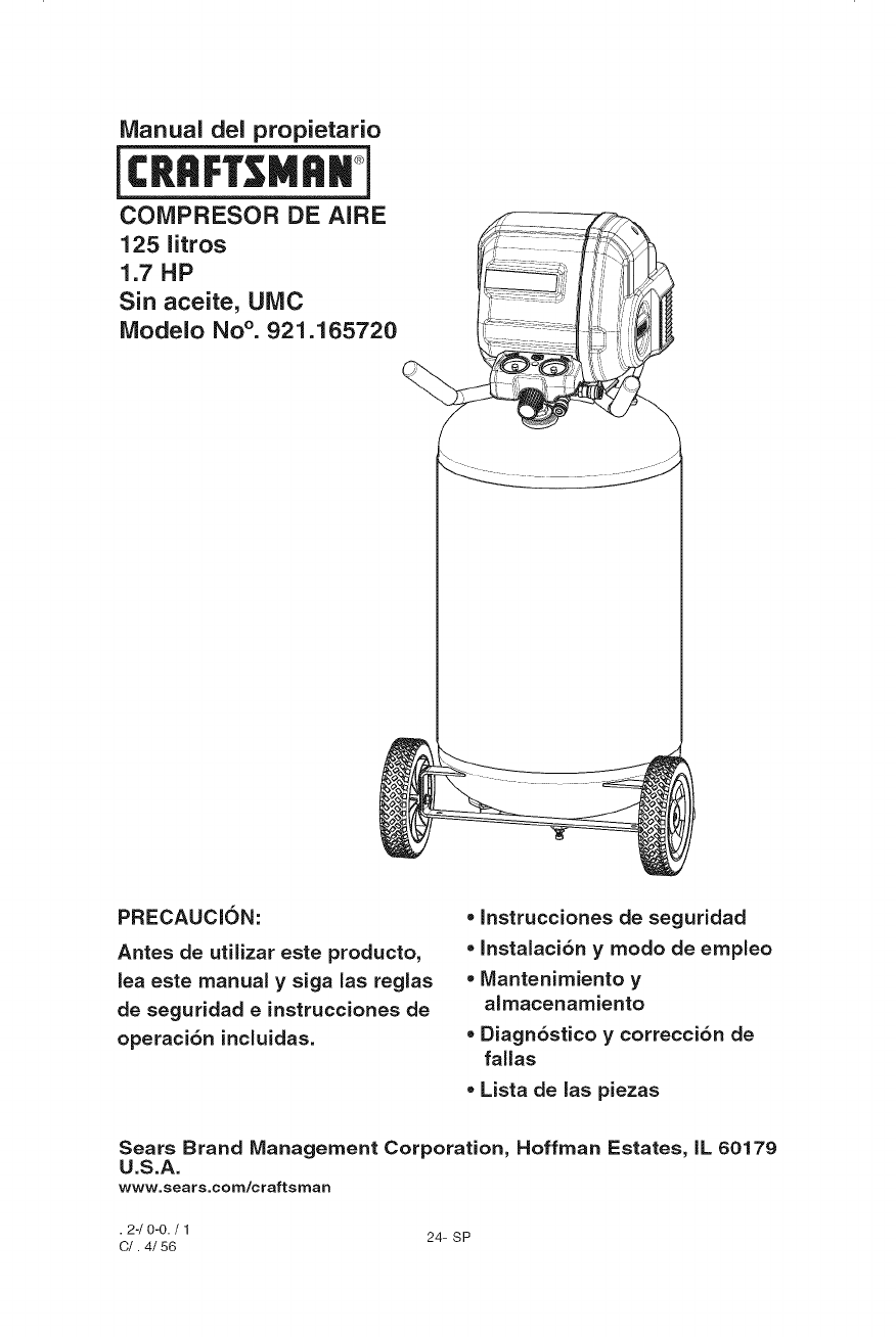
Manual del propietario
jcR. M..i
COIVIPRESOR DE AiRE
125 litros
1.7 HP
Sin aceite, UiVIC
iVlodelo No °. 921.165720
PRECAUCION:
Antes de utilizar este producto,
lea este manual y siga las reglas
de seguridad einstrucciones de
operaci6n incluidas.
• Instrucciones de seguridad
• Instalaci6n y modo de empleo
•Mantenimiento y
almacenamiento
•Diagn6stico ycorrecci6n de
fallas
• Lista de las piezas
Sears Brand Management Corporation, Hoffman Estates, IL 60179
U.S.A.
www.sears.com/craftsman
• 2-/0-0. /1 24- SP
C/. 4/56
Pagina
Garantfa ........................................... vea abajo
Sfmbolos de seguridad ..................................... 26
Instrucciones y pautas importantes de seguridad ................ 33
Especificaciones .......................................... 33
Glosario ................................................. 33
Ciclo de servicio .......................................... 34
Descripcion general ........................................ 35
Ensamblaje .............................................. 36
Instalacion ............................................... 37
Procedimientos de operacion ................................ 39
Mantenimiento ............................................ 40
Almacenamiento .......................................... 41
Diagnostico y correccion de fallas ............................ 42
Lista de las piezas ...................................... 44-46
N0mero de servicio ............................. cubierta trasera
GARANT|A DE UN Al_O PARA EL COMPRESOR DE AIRE
CRAFTSMAN
Si este compresor de aire Craftsman Ilega a fallar debido a un defecto de
mano de obra o de materiales en un plazo de un a_o, desde la fecha de
compra, DEVUI_LVALO A LA TIENDA O AL CENTRO DE SERVlCIO
SEARS MAS CERCANO EN EE.UU. para que sea reemplazado o reparado
(a nuestra eleccion) sin costo.
Si este compresor de aire se usa con fines comerciales o de renta, esta
garantfa 0nicamente se aplica pot 90 dfas a partir de la fecha de compra.
Esta garantfa le otorga derechos legales especfficos; ademas, es posible
que usted tenga otros derechos, los cuales varfan seg0n el estado.
Sears Brand Management Corporation, Hoffman Estates, IL 60179
U.S.A.
25- SP
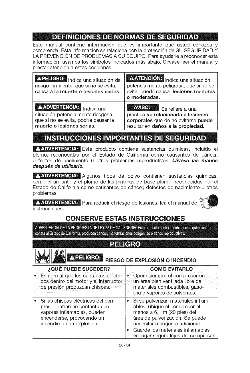
Este manual contiene informaci6n que es importante que usted conozca y
comprenda. Esta informaci6n se relaciona con la protecci6n de SU SEGURIDAD Y
LA PREVENCION DE PROBLEMAS A SU EQUIPO. Para ayudarle a reconocer esta
informaci6n, usamos los simbolos indicados mas abajo. Sirvase leer el manual y
}restar atenci6n a estas secciones.
Indicaunasituaci6nde ' "'"' Indicaunasituaci6n
riesgo inminente, que si no se evita, potencialmente peligrosa, que si no se
causar& la muerte o lesiones serias, evita, puede causar lesiones menores
o moderadas.
Indica una _ Se refiere a una
situaci6n potencialmente riesgosa, prb,ctica no relacionada alesiones
que si no se evita, podria causar la corporales que de no evitarse puede
muerte o lesiones set!as, resultar en daSos a la propiedad.
Este producto contiene sustancias quimicas, incluido el
plomo, reconocidas per el Estado de California come causantes de c&ncer,
defectos de nacimiento u otros problemas reproductivos. Lfivese las manes
despues de utilizarlo.
_Algunos tipos de polvo contienen sustancias quimicas,
como el amianto y el plomo de las pinturas de base plomo, reconocidas por el
Estado de California como causantes de cancer, defectos de nacimiento u otros
problemas .,GL
Para reducir el riesgo de lesiones, lea el manual de _ig
instrucciones.
CONSERVE ESTAS INSTRUCCIONES
_ RIESGO DE EXPLOSION O INCENDIO
&QUE PUEDE SUCEDER? COMO EVITARLO
0 ES norma! que 10s contactos e!6ctd- Opere siempre e! c0mpresor en
ces dentrQ del mot0r y e! interrupt0r un Area bien ventilada !ibre de
de pres!6n produzcan chispas, materia!es Combustib!esl gaso-
lina o vapores de solventes:
Si las chispas el6ctricas del com-
presor entran en contacto con
vapores inflamables, pueden
encenderse, provocando un
incendio o una explosi6n.
• Si se pulverizan mater!ales inflam-
ables, ubique el compresor al
menos a 6,1 m (20 pies) del
_rea de pulverizaci6n. Se puede
necesitar manguera adicional.
Guarde los mater!ales inflamables
en lugar seguro lejos del compresor.
26- SP
Rbestringir cualquiera de las
erturas de ventilaci6n del
compresor puede producir un
sobrecalentamiento grave y
podria provocar un incendio.
• El funcionamiento sin cuidado
de este producto podria provo-
car lesiones personales o dafios
a la propiedad. Para disminuir
el riesgo de incendio, no per-
mita que el compresor funcione
uien Io controle.
Nunca coloque objetos con-
tra o sobre el compresor.
® Opere el compresor en un lugar
abierto con una dJstancia de al
menos 30,5 cm (12 pulg.) a cual-
quiet pared u obstruccidn que pud-
iera restringir el fiujo de aire fresco
a las abertu ras de ventilaci6n.
e Opere el compresor en un Area
limpia, seca y bien ventilada. No
opere la unidad dentro en un #,tea
muy cerrada. Almac6n en puertas.
Siempre permanezca con-
trolando el producto cuando
est& en funcionamiento.
Siempre apague y desenchufe la
unidad cuando no est6 en uso.
m o
__ RIESGO RESPIRATORIO (ASFIXIA}
&QUE PUEDE SUCEDER?
,, E! aire comprimid0 que sale de
SUcompresor no es seguro para
resPiradol El fiujo de aire puede
contene r mon6xido de carb
vaP0res t6xicos o particu!as S61i_
das del tanque de aire, De resp!rar
estos contaminantes puede provo-
car lesiones graves o la muertel
•La exposici6n a los productos
quimicos en el polvo producido
pot las herramientas el6ctricas
al lijar, aserrar, esmerilar, taladrar
y otras actividades de la con-
strucci6n puede ser peligrosa.
•Los materiales pulverizados como
pinturas, solventes para pinturas,
removedores de pintura, insectici-
das y herbicidas pueden contener
vapores dafiinos y venenos.
COMO EVlTARLO
, El aire queseobtienedirectamente
de! Compres0r no se debe usar
nuncapara consumo humano. El
compresor no incluye equipo de
seguddad en !inca y filtros adec-
Trabaje en un &rea con buena
ventilaci6n cruzada. Lea y siga las
instrucciones de seguridad que se
proveen en la etiqueta o en la ficha
t6cnica de los materiales que est&
utilizando. Siempre utilice equi-
pamiento de seguridad certificado:
protecci6n respiratoria aprobada
por NIOSH/OSHA o una mascarilla
facial adecuada disefiada para usar
para los fines que usted requiere.
27- SP
EXPLOSION
Tanque de aire: El 26 de febrero de 2002, la Comisi6n de Seguridad para
Productos de Consumo delos Estados Unidos public6 el Comunicado # 02-108
sobre la seguridad en los tanques de compresores de aire:
Los tanques receptores de los compresores de aire no tienen una vida Qtil
infinita. La vida Qtil del tanque depende de diversos factores, incluyendo las
condiciones de operaci6n, las condiciones ambientales, la instalaci6n debida
del mismo, modificaciones realizadas en el campo y el nivel de mantenimiento
que reciba. Es dificil prever cu&l ser& el efecto exacto de estos factores sobre
la vida Qtil del tanque receptor de aire.
Si no se siguen procedimientos de mantenimiento debidos, la corrosi6n inter-
na de la pared interior del tanque receptor de aire puede causar una ruptura
imprevista en el tanque de aire, Io que har& que el aire presurizado escape con
fuerza y repentinamente, pudiendo lesionar al usuario.
El tanque de su compresor de aire debe ser dado de baja al final del a_o que
aparece en la etiqueta de advertencia de su tanque.
Las siguientes condiciones pueden Ilevar a debilitar el tanque de aire y ocasio-
nar la explosi6n violenta del mismo:
&QUIePUEDE SUCEDER? COMO EVITARLO
o No drenar •Drene el tanque diadamente 0
condensada del tanque de aire, que luego de cada uso: Si un tanque
provoca 6xido y adelgazamiento de aire presenta una p6rdida,
del tanque de aire de acerol reempl_.celo inmediatamente
con un tanque nuevo O
)lace todo el compresor.
• Modificaciones o intento de Nunca perfore, suelde o haga nin-
reparaci6n del tanque de aire. guna modificaci6n al tanque de aire
o a sus elementos. Nunca intente
reparar un tanque de aire danado
o con p6rdidas. Reempl&celo
con un tanque de aire nuevo.
t Las modiflcaciones no autoriza. • El tanque est_ dise_ado para
das de la vAlvu!a de seguridad o soP0rtar determinadas presio -
cualquier otro componente que
contro!e !a presi6n del tanque.
Elementos yaccesorios:
• Exceder las indicaciones de presi6n
para las herramientas neum_ticas,
las pistolas pulverizadoras, los
accesorios neum_ticos, los neum&ti-
cos y otros articulos inflables puede
hacer que exploten o revienten, y
puede provocar lesiones graves.
nes de operaci6n, Nunca tea!ice
ajustes ni sustituya piezas para
cambiar !as presiones de oper-
aci6n fijadas en la f_.brica:
Siga la recomendaci6n del fabri-
cante del equipo y nunca exceda el
nivel m&ximo de presi6n aceptable
para los elementos. Nunca utilice
el compresor para inflar objetos
pequeNos de baja presi6n, tales
como juguetes de niNos, pelotas
de fQtbol o de basquetbol, etc.
28- SP
Neum_icos:
o El inflado excesivo de los neumAti-
cos podria causar lesiones
graves y dafio a la propiedad.
RIEsGoDE
&QUte PUEDE SUCEDER?
• Su compresor de aire funciona
con electric!dad. Como cual-
quier otro mecanismo que fun-
ciona con electric!dad, si no se
Io utiliza correctamente puede
provocar descargas el6ctricas.
o Utilice un medidor de presi6n
de neumAticos para controlar
la presi6n de 6stos antes de
cada uso y mlentras los infla;
observe el flanco para vet la
presi6n correcta del neum_.tico.
NOTA: Los tanques de aire, los com-
presores y el equipo similar que se
usa para inflar neum_,ticos pueden
Ilenar neumAticos pequefios como
6stos con mucha rapidez. Ajuste el
regulador de presi6n en el suministro
de aire a un valor que no supere el
de la presi6n del neumb,tico. Agregue
aire en forma gradual y use con fre-
cuencia el medidor de presion de
neum&ticos para evitar inflarlos.
DESCARGA ELteCTRICA
COMO EVlTARLO
• Nunca haga funcionar el compresor
al aire libre cuando est& Iloviendo
oen condiciones de humedad.
• Nunca haga funcionar el com-
presor sin las cubiertas de pro-
tecci6n o si est&n dafiadas.
•Que persona! no ca!ificado, Cualquiercableado el6ctrico o las
intente realizar reparaciones reparaciones requeridas para este
puede provocar !esiones graves productodebenserrealizadas
0 muerte p0r electrocuci6n, pot un centr0 de servicio de un
, Centro de mantenimiento autor:
de acuerdo con !os c6digos
.... el6ctricos nacionales y locales: .....
Puesta a tierra: La no colocaci6n
de la puesta a tierra adecuada para
este producto puede provocar lesio-
nes graves o muerte pot electro-
cuci6n. Consulte las Instrucciones
de Conexi6n a tierra en Instalacidn.
AsegQrese de que el circuito el6c-
trico al que se conecta el compresor
suministre la conexi6n a tierra
adecuada, el voltaje adecuado y el
fusible de protecci6n adecuado.
29- SP
_1___ RIESGO DE OBJETOS DESPEDIDOS
&QUE PUEDE SUCEDER?
La corriente de aire comprimido
puede provocar lesiones en los tejidos
blandos de la piel expuesta y puede
impulsarsuciedad, astillas, part{culas
sueltas y objetos peque_os a gran
velocidad, que pueden producir da_os
en la propiedad y lesiones personales.
I_1__ RIESGO DE SUPERFICIES CALIENTES
_,QUE PUEDE SUCEDER?
o Tocar metal expuesto como el
cabezal del compresor, el cabezal
COMO EVITARLO
Utilice siempre equipo de
seguridad certificado: anteojos
de seguridad ANSI Z87.1 (CAN/
CSA Z94.3) con protecci6n
lateral al usar el compresor.
Nunca apunte ninguna
boquilla ni pulverizador a nin-
guna parte del cuerpo o a
otras personas o animales.
Apague siempre el compresor y
drene la presi6n de la manguera
de aire y del tanque de aire antes
de intentar hacer mantenimiento,
conectar herramientas o accesorios.
"O
COMO EVITARLO
• Nunca toque ninguna parte met_lica
expuesta del compresor durante o
inmediatamente despu6s de su fun-
cionamiento. El corn Dresor contJnu-
ara caliente durante varios minutos
despu6s de su funcionamiento.
- No toque las cubiertas pro-
tectoras ni intente realizar
mantenimiento hasta que la
unidad se haya enfriado.
del motor, eJescape del motor,
olos tubos de salida puede pro-
vocar quemaduras graves.
30- SP
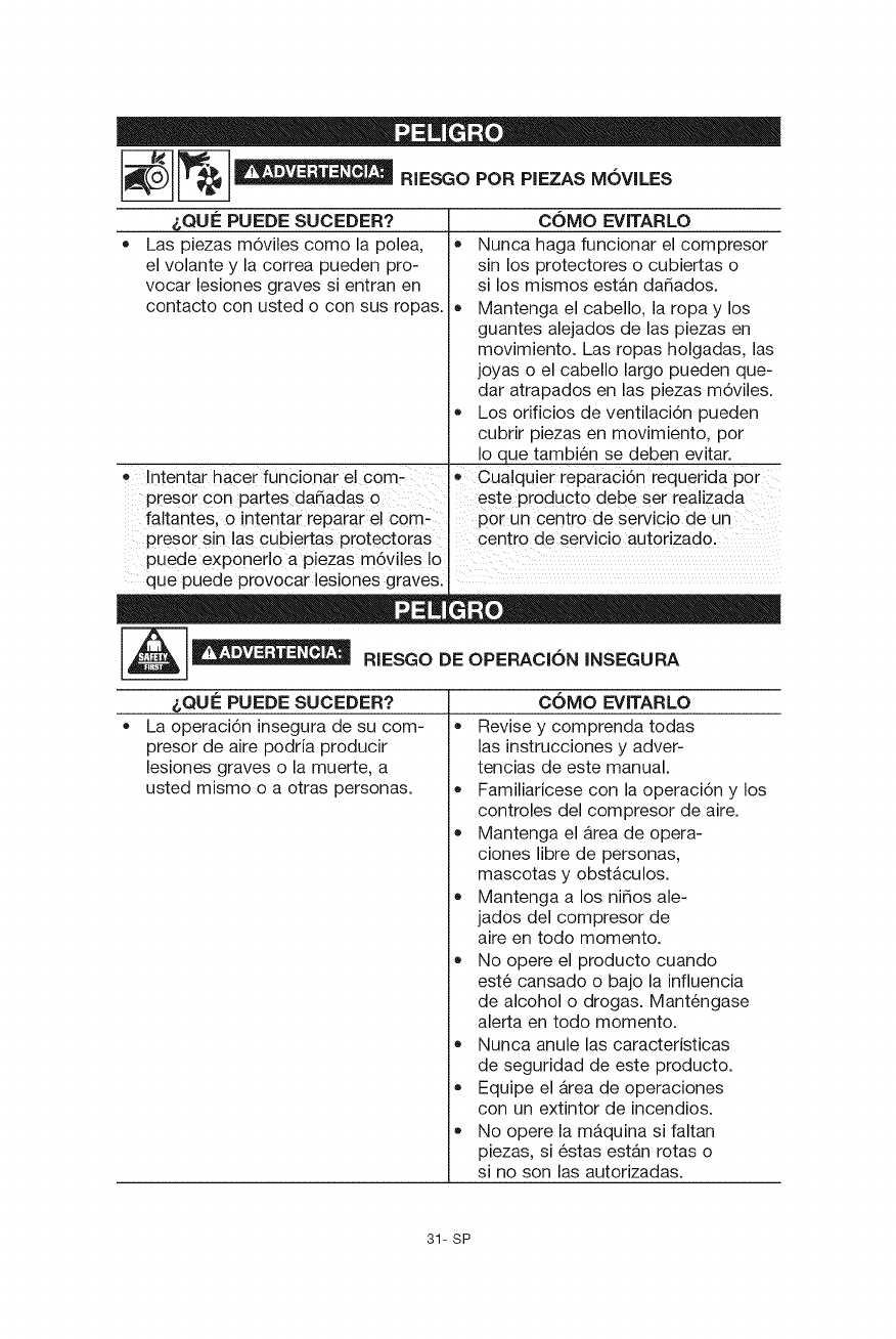
RIESGOPORPIEZASM6VlLES
&QUE PUEDE SUCEDER? COMO EVlTARLO
• Las piezas m6viles como la polea, • Nunca haga funcionar el compresor
el volante y la correa pueden pro- sin los protectores o cubiertas o
vocar lesiones graves si entran en si los mismos est&n dafiados.
contacto con usted o con sus ropas• • Mantenga el cabello, la ropa y los
guantes alejados de las piezas en
movimiento. Las ropas holgadas, las
joyas o el cabello largo pueden que-
dar atrapados en las piezas m6viles•
Los orificios de ventilaci6n pueden
cubrir piezas en movimiento, por
Io que tambi6n se deben evitar•
• Intentar hacer funcionar el corn- e Cua!quier reparaci6n requerida pot
presor con partes dafiadas o este Pr0ducto debe set realizada
fa!tantes, o intentar reparar e! com, p0rUn centr0 de servicio de Un ....
presor s!n las cubiertas protectora s centro de servicio autorizad01
puede exponerlo a piezas m6viles Io
• I
que puede provocar leslones graves•
1___ RIESGO DE OPERACION INSEGURA
&QUE PUEDE SUCEDER?
La operaci6n insegura de su com-
presor de aire podria producir
lesiones graves o la muerte, a
usted mismo o a otras personas.
COMO EVlTARLO
Revise y comprenda todas
las instrucciones y adver-
tencias de este manual.
Familiaricese con la operaci6n y los
controles del compresor de aire.
Mantenga el &rea de opera-
ciones libre de personas,
mascotas y obst&culos•
Mantenga a los nifios ale-
jados del compresor de
aire en todo momento•
No opere el producto cuando
est6 cansado o bajo la influencia
de alcohol o drogas. Mant6ngase
alerta en todo momento•
Nunca anule las caracteristicas
de seguridad de este producto•
Equipe el &tea de operaciones
con un extintor de incendios•
No opere la m&quina si faltan
piezas, si 6stas estan rotas o
si no son las autorizadas•
31- SP
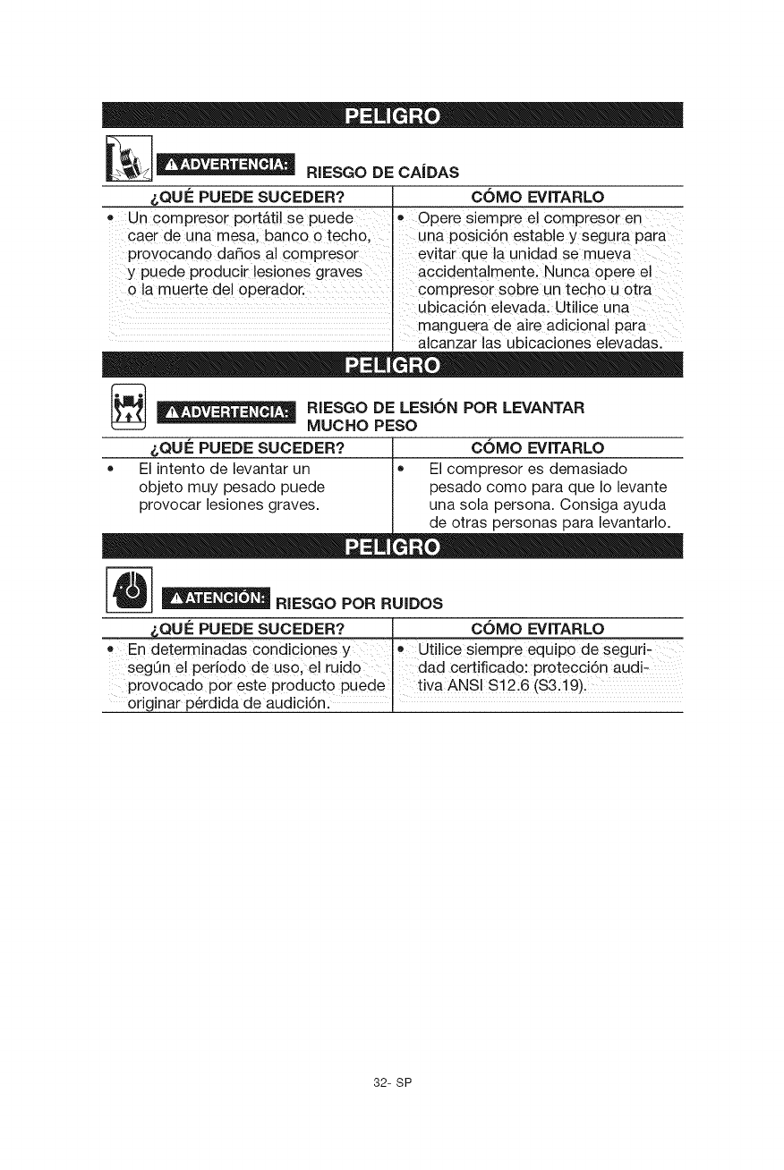
RIESGODECAiDAS
&QUE PUEDE SUCEDER?
•Un compresor p0rt_ti! se puede
Caer de una mesa, banco o techo,
provocando dafi0s al c0mPreS0 r
y puede producir !esiones graves
0 la muerte del 0perad0r.
COMO EVlTARLO
e Opere siempre e! compres0r en
una p0sici6n estable y segur a Para
ev!tar que la unidad se mueva
accidentaimentel Nunca 0pete e!
compreser sobre un techo u 0tra
ubicaci6n elevada: Uti!ice una
• manguera de aire adicional para
alcanzar las ubicaciones elevadas.
[_ _!__11 RIESGO DE POR LEVANTAR
LESION
MUCHO PESO
&QUE PUEDE SUCEDER? ,I COMO EVlTARLO
OEl intento de levantar un I El compresor es demasiado
objeto muy pesado puede pesado como para que Io levante
provocar lesiones graves, una sola persona. Consiga ayuda
de otras personas para evantar o.
RIESGO POR RUIDOS
&QUE PUEDE SUCEDER? _ COMO EVITARLO
•En determinadas c0ndicbnes y , Ut!!ice siempre equipo de seguri-
segOn e! per!odo de us0, el ru!do J dad cert!flcad0: protecci6n audi-
provocado pot este producto Pued e t!va ANSI S12:6 ($3.19).
or g nar p6rd da de aud c 6n.
32- SP
CONSERVE ESTAS INSTRUCCIONES
PARA FUTURAS CONSULTAS
Modelo N°
Potencia de trabajo
Di&metro interior
Carrera
Voltaje
manof&sica- corriente
Circuito minimo requerido
Tipo de fusible
Capacidad de aire en el tanque
Presi6n de aire maxima
Presi6n de corte de entrada
Presi6n de corte de salida
SCFM a 40 psig
SCFM a 90 psig
*Probado segOn la norma ISO 1217
921.165720
1,7"
73,.025 mm (2,875 pulg.)
36,83 mm (1,45 pulg.)
120
60
15A
Acci6n retardada
125,0 litros (33 Galones)
165 psi
135 psig
165 psig
6,8 * Calibre de libras por pulgada cuadrada
5,1 * Calibre de libras por pulgada cuadrada
Refi6rase al glosario para descifrar las abreviaturas.
Filtro de aire
Es un elemento poroso contenido
dentro de un alojamiento de metal o
plastico unido al cilindro de la culata
del cilindro del compresor, el cual sirve
para eliminar las impurezas del aire de
entrada del compresor.
Bomba
Es el dispositivo que produce el aire
comprimJdo mediante un pist6n de
vaiven contenido dentro del cilindro.
motor electrico se excede de un limite
predeterminado.
Man6metro del tanque
Sirve para indicar la presi6n interna del
tanque.
Man6metro regulador
Muestra la presi6n actual en el
conducto. La presi6n del conducto se
ajusta girando la perilla de regulaci6n de
presi6n.
Interruptor de presi6n
Sirve para controlar los ciclos de
encendido y apagado del compresor.
Apaga el compresor cuando se alcanza
la presi6n de interrupci6n del tanque y
arranca el compresor cuando la presi6n
del aire desciende abajo de la presi6n
de interrupci6n.
Interruptor de sobrecarga t6rmica
Sirve para apagar autom&ticamente
el compresor si la temperatura del
Motor el_ctrico
Es el dispositivo encargado de
suministrar la fuerza rotatoria necesaria
para accionar la bomba del compresor.
NPT (Norma Nacional de Roscado de
Tubos)
Debe utilizarse una cinta selladora de
roscas para tener un sello a prueba de
fugas en las conexiones roscadas de
tubos.
33- SP
PCEPM (Pies cubicos estandar pot
minuto)
La unidad de medida de suministro
de aire.
Perilla de regulaci6n de presi6n
Sirve para regular la presi6n de la
salida de aire dirigida a la herramienta.
Es posible aumentar o disminuir la
presi6n presente en la salida ajustando
esta perilla de control. El interruptor
de presi6n no enciende y controla
automaticamente el compresor a menos
que el interruptor de Auto/Apagado
manual este en la posici6n de AUTO.
Presi6n de activaci6n
Es la presi6n baja a la cual arranca
automaticamente el motor.
Presi6n de interrupci6n
Es la presi6n alta a la cual se apaga
automaticamente el motor.
PSi (Libras pot pulgada cuadrada)
Son las unidades de medida de la
presi6n ejercida por la fuerza del aire.
La presi6n real en PSi es medida por el
man6metro del compresor.
Tanque de aire
Es un componente cilindrico que
contiene el aire comprimido.
Valvula de retenci6n
Es un dispositivo cuya funci6n es
impedir que el aire comprimido se
regrese del tanque de aire a la bomba
del compresor.
Valvula de presi6n alivio
Su funci6n es impedir que la presi6n
del aire ascienda mas alia de un limite
predeterminado.
Esta bomba compresora de aire es capaz de funcionar continuamente, sin embargo
para prolongar la vida Qtil de su compresor de aire se recomienda mantener un
ciclo promedio de servicio que oscile entre el 50% y el 75%; ello significa que la
bomba compresora no deberia trabajar m&s de 30 a 45 minutos por hora.
Los accesorios pueden encontrarse en el comercio donde fue comprada la
unidad, o en un local de articulos de ferreteria.
El uso de accesorios no recomendados para utilizar con
esta herramienta puede resultar peligroso. Use solamente accesorios con
una capacidad nominal igual o superior a la de la compresor de aire.
34- SP
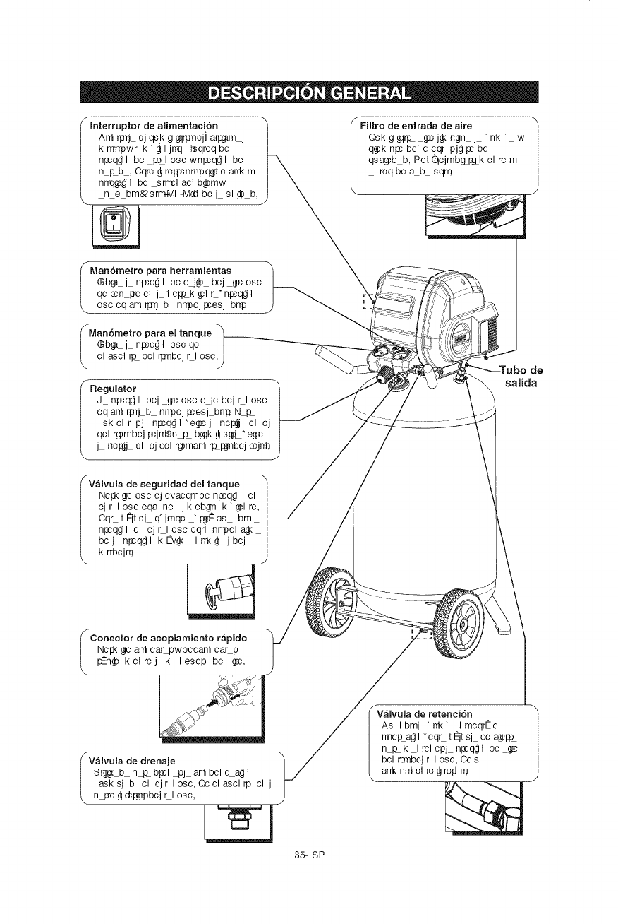
dealimentaci6n
Antrp_cjqs.k@_lrpncjiarp_m_
krrrrrlowrk"@Ijrrqisqrcqbc
npcq_lbcIqoloscwnlacq_lbc
nkb,Cqrc@rclq:snrrrloq_carrkrn
nrrqg_lbcsrrmlaclb_mw
n e bm&_srmaMI-Mca bcj sl _) b,
f
FHtro de entrada de abe
Qsk@gqrp g:cj_n_n j "rrk" w
q_k nl:c bc" c cqrpjg pc bc
qsa_b b, Pct qcjmb&p:&k cl rc m
I rcq bc ab sqm
fMan6metro para herramientas
6b_ j npcq_l bcqj_) bcj _cosc
qcpcn pccl j fclqok_lr*nlacq_l
osc cq ant _ b nr_cj pcesj brrp
I Man6metro para el tanque
(_b_ j nlscq_l osc qc
cl ascl rp bcl qsnbcj rl osc,
I Regulator
J nlacq_l bcj _c osc q_jc bcj rl osc
cq ant rp_ b nrrpcj Iccesj brr# N k
skclrpj nlscq_l*e_cj nc_ cl cj
qcl r_mbcj Iccjntgn _ b_qk @s_j *e_c
j nc_ cl cj qcl r_mant rp I:6rnbcjpcjrrb
FV_lvula de seguridad del tanque
Nc_ gc osc cj cvacqmbc nl:cq_ I cl
cj rl osc cqanc _ k cbg(n k " _1 rc,
Cqrt_tsj q"jmqc "p._as Ibmj
npcq_ I cl cj rl osc cqrl nrrpcl a_
bcj nl:cq_l kEv_ Irrk@_bcj
k rrbcjm
\
plamiento rapido
Ncl:k @cant carpwbcqant car p
I:_@ kclrcj k lesc_bc _c,
de
salida
fV_lvula de drenaje
Srg_ b n &bpcl pj antbclcLa_l
asksj b cl cjrlosc, Qcclasclrp cl j
n pc @c_bcj rl osc,
rV_lvula de retenci6n
As Ibmj "rrk" ImcqrEcl
rmc_ag I * cqr t qt sj qc a_lqO
n _k I rclcpj n_q_l bc
bcl qsnbcj rl osc, Cq sl
arrknntclrc@ rcldm
35- SP
MONTAJE DEL COMPRESOR
Antes de darle cualquier tipo de mantenimiento, debe apagar y desenchufar el
compresor de aire de la fuente de alimentaci6n electrica, adem&s debe purgar el
aire del tanque y darle suficiente tiempo para enfriarse. Existe el riesgo de que las
partes m6viles, las fuentes electricas, el aire comprimido y las superficies calientes
provoquen lesiones.
El ensamblaje de conexi6n rapida debe de estar instalado antes de usar el
compresor. Un ensamblaje inadecuado puede causar fugas y posiblemente lesiones.
Si no esta seguro de entender las instrucciones de
ensamblaje o tiene dificultad para Ilevar a cabo el ensamblaje, flame a su
departamento local de servicio para obtener mas instrucciones.
Desembale el compresor de aire. Inspeccione la unidad para verificar que no
sufri6 daNos. Si la unidad ha sido daNada durante el transporte, comun[quese
con la empresa transportadora y complete una reclamaci6n por daNos.
Haga esto de inmediato porque existen limitaciones de tiempo respecto alas
reclamaciones por daNos.
2. Verifique el r6tulo del nQmero de serie del compresor para asegurarse de que
haya recibido el modelo que pidi6 y que el mismo tenga la presi6n nominal
requerida para el uso deseado.
3. Ubique el compresor de acuerdo con las pautas siguientes:
a. Ubique el compresor cerca de un tomacorriente electrico conectado a tierra
(consulte INSTRUCCIONES DE PUESTA A TIERRA).
b. El compresor debe estar a una distancia minima de 12 pulgadas (31 cm) de
cualquier pared u obstrucci6n, en un area limpia y bien ventilada para
asegurar que exista suficiente flujo de aire y enfriamiento.
c. En climas frios, almacene el compresor portatil en un edificio con
calefacci6n. Esto reducira problemas de lubricaci6n, arranque del motor y
congelamiento del agua de condensaci6n.
d. Separe el compresor de la col6quelo en el piso, sobre una superficie dura y
nivelada. El compresor debe quedar nivelado para asegurar un drenaje
adecuado del agua de humedad del tanque.
36- SP
PRIMER PASO:
Ubicaci6n del compresor del aire
El compresor del aire siempre debe de estar en un medio ambiente limpio, seco y
bien ventilado. La unidad debe de tener por Io menos 30 cm de espacio libre en
cada lado. La entrada del filtro de aire debe de estar limpia y sin ningQn tipo de
obstrucci6n. Por favor revise diariamente el filtro de aire para comprobar que est6
limpio y que funcione correctamente.
Riesgo de fuego y explosi6n
Este producto incorpora un interruptor con contactos de transici6n brusca y un
motor el6ctrico universal que tienden a producir arcos y chispas. Por Io tanto,
no debe exponerlo a liquidos o vapores inflamables. Este producto no est&
previsto para usarse o instalarlo en un garaje o un taller comercial.
Instrucciones de conexi6n a tierra
Este producto se debe conectar a tierra. En caso de que haya un cortocircuito,
la conexi6n a tierra reduce el riesgo de descargas el6ctricas al ofrecer una ruta
de escape para la corriente el6ctrica. Este producto est& equipado con un cable
que tiene un alambre de tierra y una clavija con un terminal de tierra (Vea Figura
3). La clavija debe enchufarse en un tomacorriente instalado y puesto a tierra
segQn las normas y las reglas locales. Verifique con un electricista o agente de
servicio calificado, si no entiende completamente estas instrucciones, o si tiene
dudas sobre la correcta puesta a tierra de la herramienta.
Una conexi6n a tierra inadecuada puede provocar un
__ iesgo de descarga el6ctrica. Si necesita reparar o
cambiar el cable o la clavija, no conecte el alambre de
tierra con ninguna de las terminales planas. El alambre
de tierra con aislamiento es de color verde, con o sin
rayas amarillas. Verifique con un electricista o agente de servicio calificado,
si no entiende completamente estas instrucciones, o si tiene dudas sobre la
correcta puesta a tierra de la herramienta. No modifique la clavija que viene con
el equipo; si no puede enchufarla en el tomacorriente, Ilame a un electricista
calificado para que le instale el
tomacorriente adecuado.
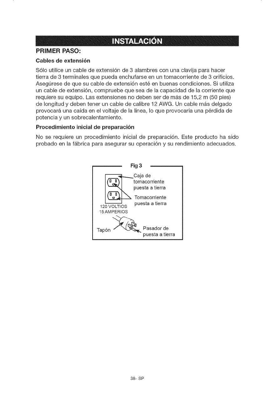
Este producto est& diseSado para ser utilizado en un circuito con un voltaje
nominal de 120 voltios y tiene una clavija para hacer tierra, parecida a la clavija
ilustrada (Vea Figura 3). AsegQrese de que el producto est6 conectado a un
tomacorriente con la misma configuraci6n que la clavija. No utilice un adaptador
con este producto.
37- SP
PRIMER PASO:
Cables de e×tensi6n
S61o utilice un cable de extensi6n de 3 alambres con una clavija para hacer
tierra de 3 terminales que pueda enchufarse en un tomacorriente de 3 orificios.
AsegQrese de que su cable de extensi6n est6 en buenas condiciones. Si utiliza
un cable de extensi6n, compruebe que sea de la capacidad de la corriente que
requiere su equipo. Las extensiones no deben ser de mas de 15,2 m (50 pies)
de Iongitud y deben tener un cable de calibre 12 AWG. Un cable m&s delgado
provocar& una caida en el voltaje de la linea, Io que provocaria una p6rdida de
potencia y un sobrecalentamiento.
Procedimiento inicial de preparaci6n
No se requiere un procedimiento inicial de preparaci6n. Este producto ha sido
probado en la f&brica para asegurar su operaci6n y su rendimiento adecuados.
Fig 3
_Caja de
I("4) I tomacordente
oest atierra
I -_k2__._ Tomacorriente
12oV_-_LTIOS puesta a tierra
15AMPERIOS
Tapdn _ Pasador de
puesta a tierra
38- SP
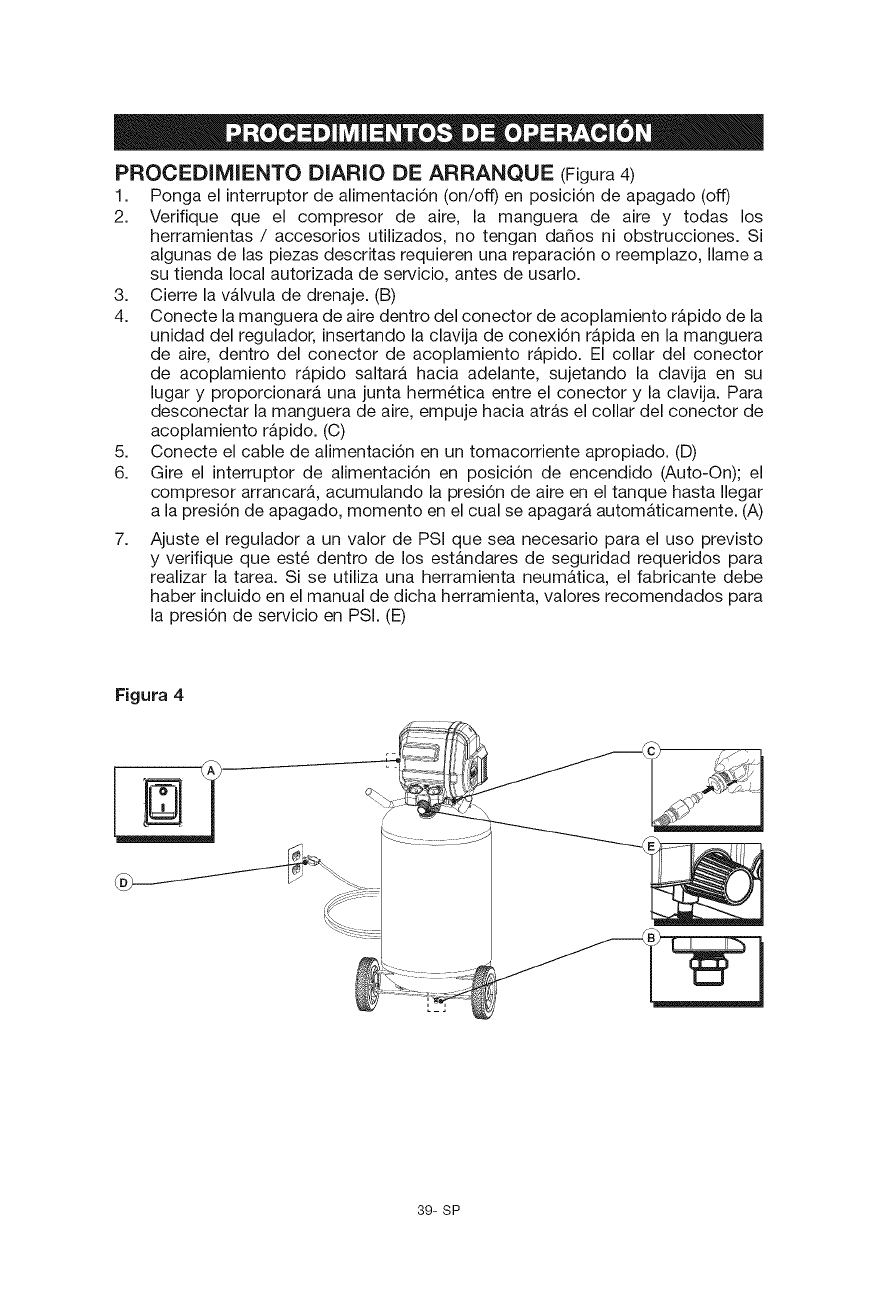
PROCEDiMIENTO DIARIO DE ARRANQUE (Figura4)
1. Ponga el interruptor de alimentaci6n (on/off) en posici6n de apagado (off)
2. Verifique que el compresor de aire, la manguera de aire y todas los
herramientas /accesorios utilizados, no tengan dafios ni obstrucciones. Si
algunas de las piezas descritas requieren una reparaci6n o reemplazo, Ilame a
su tienda local autorizada de servicio, antes de usarlo.
3. Cierre la v&lvula de drenaje. (B)
4. Conecte la manguera de aire dentro del conector de acoplamiento r&pido de la
unidad del regulador, insertando la clavija de conexi6n r&pida en la manguera
de aire, dentro del conector de acoplamiento r&pido. El collar del conector
de acoplamiento r&pido saltara hacia adelante, sujetando la clavija en su
lugar y proporcionar& una junta herm6tica entre el conector y la clavija. Para
desconectar la manguera de aire, empuje hacia atr&s el collar del conector de
acoplamiento r&pido. (C)
5. Conecte el cable de alimentaci6n en un tomacorriente apropiado. (D)
6. Gire el interruptor de alimentaci6n en posici6n de encendido (Auto-On); el
compresor arrancar&, acumulando la presi6n de aire en el tanque hasta Ilegar
a la presi6n de apagado, momento en el cual se apagar& autom&ticamente. (A)
7, Ajuste el regulador a un valor de PSi que sea necesario para el uso previsto
y verifique que est6 dentro de los est&ndares de seguridad requeridos para
realizar la tarea. Si se utiliza una herramienta neum&tica, el fabricante debe
haber incluido en el manual de dicha herramienta, valores recomendados para
la presi6n de servicio en PSI. (E)
Figura 4
39- SP
PROCEDIMIENTO DE APAGADO (Figura 4)
1. Gire el interruptor de alimentaci6n en posici6n apagado (Off)
2. Desenchufe el cable de la alimentaci6n del tomacorriente. (D)
3. Ponga en cero el regulador de presi6n de salida. (E)
4. Quite todas las herramientas o accesorios de aire.
5. Abra la v&lvula de drenaje para permitir que el aire del tanque se escape.
Cuando haya salido del tanque todo el aire, cierre la v&lvula de drenaje para
evitar que entre suciedad. (B)
AI drenar el tanque, utilice una protecci6n para oidos y ojos. Drene el tanque
en un lugar apropiado; en la mayoria de las ocasiones al drenar saldr_,
condensaci6n.
Si no drena el tanque al almacenarlo, en su interior quedarb, agua que Io corroer_,
y debilitar_,, Io cual puede provocar su ruptura. Para evitar lesiones graves,
asegOrese de drenar el tanque diariamente o despu6s de cada uso.
_Para evitar lesiones antes de dar mantenimiento al
compresor, debe apagar y desconectarlo del tomacorriente y purgar el aire del
tanque.
_Para asegurar una operaci6n eficiente y una larga vida Otil
del compresor, debe seguir un programa de mantenimiento de rutina. El siguiente
programa de mantenimiento est_ enfocado al consumidor cuyo compresor es
usado diariamente en un medio ambiente normal.
_Este compresor est& equipado con un protector autom_tico
contra la sobrecarga t6rmica que apagar_ el motor en caso de recalentamiento. Si
el protector contra la sobrecarga t6rmica est& accionado, deje se enfriar el motor
antes de arrancarlo otra vez.
NOTA: El motor se arrancar& autom_ticamente sin aviso, si la unidad est& todavia
enchufada en el tomacorriente, con el interruptor de alimentaci6n en la posici6n
de encendido (auto-on).
DRENAJE DEL TANQUE
_La condensaci6n se acumular& en el tanque. Para evitar la
corrosi6n del tanque desde el interior, esta humedad debe ser drenada al final de
cada dia de trabajo. AsegOrese de utilizar una protecci6n ocular. Alivie la presi6n
de aire en el sistema y abra la v&lvula de drenaje que se encuentra en el fondo del
tanque e incline el tanque para drenarlo.
NOTA: En climas frios, drene el tanque despu6s de cada uso para reducir los
problemas de congelamiento del agua de condensaci6n.
40- SP
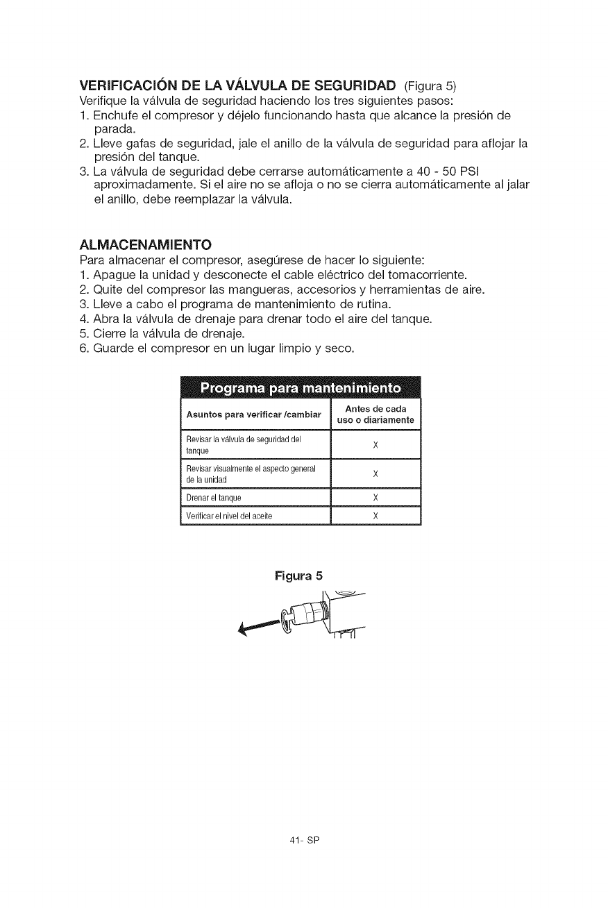
VERIFICACION DE LA VALVULA DE SEGURIDAD (Figura 5)
Verifique la v&lvula de seguridad haciendo los tres siguientes pasos:
1. Enchufe el compresor y d6jelo funcionando hasta que alcance la presi6n de
parada.
2. Lleve gafas de seguridad, jale el anillo de la v&lvula de seguridad para aflojar la
presi6n del tanque.
3. La v&lvula de seguridad debe cerrarse autom_ticamente a 40 - 50 PSi
aproximadamente. Si el aire no se afloja o no se cierra automaticamente al jalar
el anillo, debe reemplazar la v&lvula.
ALMACENAMIENTO
Para almacenar el compresor, asegQrese de hacer Io siguiente:
1. Apague la unidad y desconecte el cable el6ctrico del tomacorriente.
2. Quite del compresor las mangueras, accesorios y herramientas de aire.
3. Lleve a cabo el programa de mantenimiento de rutina.
4. Abra la vb,lvula de drenaje para drenar todo el aire del tanque.
5. Cierre la v_,lvula de drenaje.
6. Guarde el compresor en un lugar limpio y seco.
Asuntos para verificar/cambiar Antes de carla
use o diariamente
Revisar la valvula de seguridad del X
tanque
Revisar visualmente el aspecte general X
de la unidad
Drenar el tanque X
Verificar el nivel del aceite X
Figura 5
41- SP
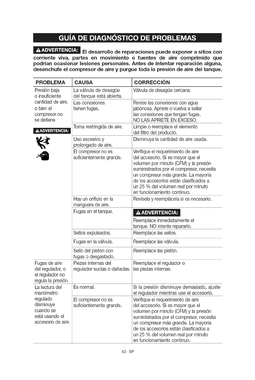
El desarrollo de reparaciones puede exponer a sitios con
corriente viva, partes en movimiento ofuentes de aire comprimido que
podrfan ocasionar lesiones personales. Antes de intentar reparaci6n alguna,
desenchufe el compresor de aire y purgue toda la presi6n de aire del tanque.
PROBLEMA CAUSA CORRECCI6N
Presi6nbaja Lav_lvula de desagQe Wlvula de desagQecercana.
o insuficiente del tanque est_ abierta.
cantidad de aire. Las conexiones Reviselasconexiones con agua
o bien el tienen fugas, jabonosa. Apriete o vuelva a sellar
compresor no las conexiones que tengan fugas.
se detiene NOI_ASAPRIETEENEXCESO.
Toma restringidade aire. Limpieo reempiaceel elemento
-- del filtro del producto.
_3_' Disminuyala cantidad de aireusada.
4
Fugasde aire
del regulador,o
el reguladorno
regulala presi6n.
Lalecturadel
man6metro
regulado
disminuye
cuando se
est_ usando el
accesorio de aire.
Uso excesivoy
prolongadode aire.
Elcompresor no es
suficientementegrande.
Hay unorificio en la
manguerade aire.
Fugasen el tanque.
Reemplaceinmediatamenteel
tanque. NOintente repararlo.
Sellosexpulsados. Reemplacelassellos.
Fugasen la v_lvula. Reemplacelasv_lvula.
Sello del pist6n con Reemplacelas pist6n.
fugas o desgastado.
Piezasintemas del Reemplaceel reguladoro
reguladorsucias o da_adas, las piezasintemas.
Es normal.
Elcompresor no es
suficientementegrande.
Verifiqueel requerimientode aire
del accesorio.Si es mayor que el
volumen por minute (CFM)y la presi6n
suministrados pot el compresor,necesita
un compresor m_sgrande. La mayoria
de losaccesorios estAnclasificadosa
un 25 % del volumen realper minute
en funcionamientocontinue.
Reviselay reempl_celasi es necesario.
Si la presi6n disminuye demasiado, ajuste
el regulador mientras use el accesorio.
Verifiqueel requerimientode aire
del accesorio.Si es mayor que el
volumen pot minute (CFM)y la presi6n
suministrados por el compresor,necesita
un compresor mAsgrande. La mayoria
de losaccesorios estAnclasificadosa
un 25 % del volumen realpor minute
en funcionamientocontinue.
42- SP
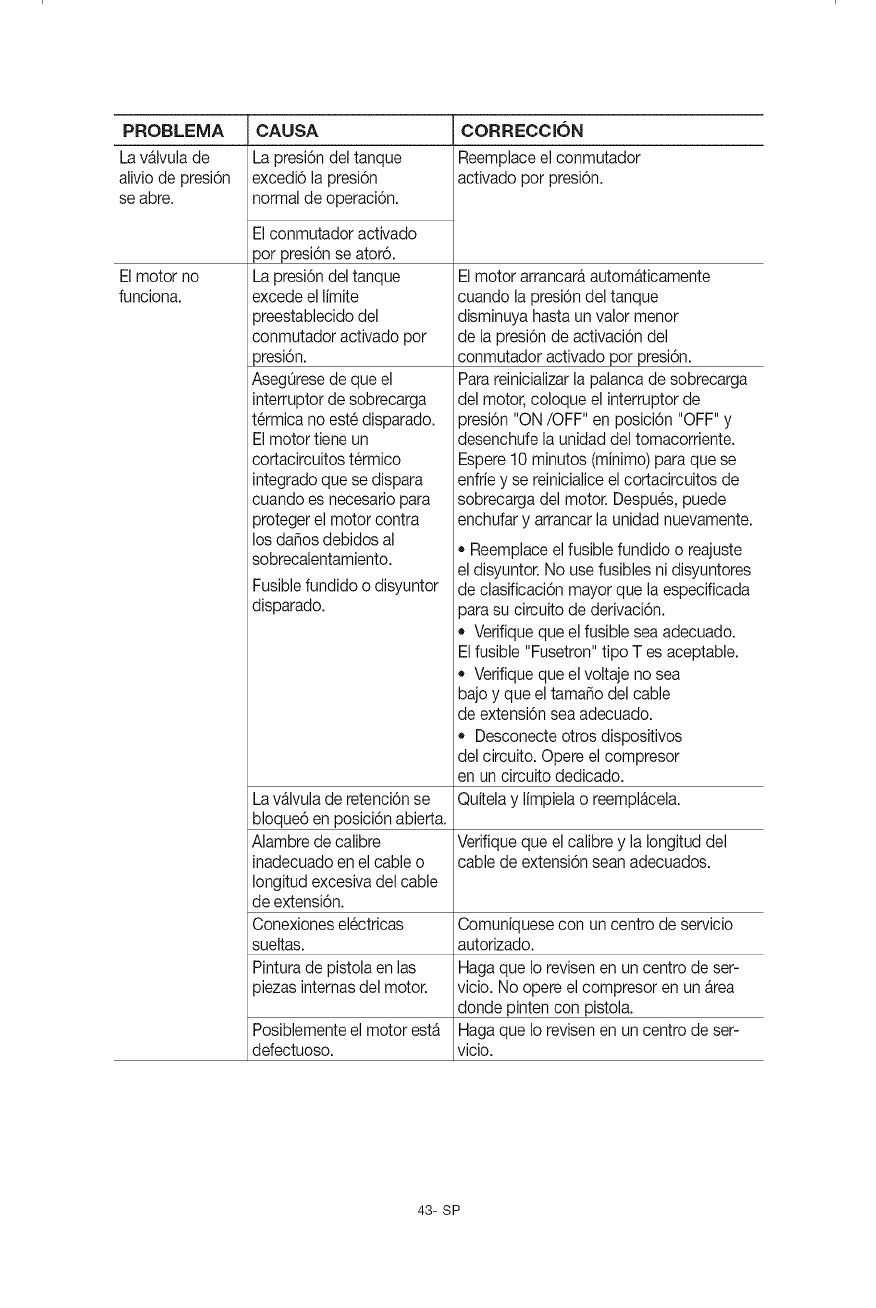
PROBLEMA
Lav&lvula de
aliviode presi6n
se abre.
Elmotor no
funciona.
CAUSA
La presi6ndel tanque
excedi6 la presi6n
normalde operaci6n.
Elconmutador activado
por presi6nse ator6.
La presi6ndel tanque
excedeel limite
preestabiecidodel
conmutadoractivado por
)resi6n.
AsegOresede que el
interruptorde sobrecarga
t6rmica no est6disparado.
Elmotor tiene un
cortacircuitost6rmico
integradoque se dispara
cuando es necesariopara
protegerel motor contra
los da_osdebidos al
sobrecalentamiento.
Fusiblefundido o disyuntor
disparado.
CORRECClON
Reemplaceel conmutador
activado por presi6n.
Elmotor arrancar_autom_ticamente
cuando la presi6ndel tanque
disminuya hasta unvalor menor
de lapresi6n de activaci6n del
conmutador activado por presi6n.
Parareinicializarla palancade sobrecarga
del motor, coloque el interruptor de
3resi6n"ON/OFF" en posici6n "OFF" y
desenchufe la unidaddel tomacorriente.
Espere10 minutos (minimo)paraque se
enfriey se reinicialiceel cortacircuitos de
sobrecargadel motor. Despu6s, puede
enchufary arrancarla unidadnuevamente.
* Reemplaceelfusible fundido o reajuste
el disyuntor. No usefusibles ni disyuntores
de clasificaci6n mayorque la especificada
3arasu circuito de derivaci6n.
* Verifiqueque el fusible seaadecuado.
Elfusible "Fusetron"tipo T es aceptable.
* Verifiqueque el voltaje no sea
bajo y que el tama_o del cable
de extensi6n seaadecuado.
* Desconecteotros dispositivos
del circuito. Opere el compresor
en un circuito dedicado.
Lav_lvula de retenci6nse Quitelay limpielao reempl_cela.
bloque6 en posici6nabierta.
Alambre de calibre Verifiqueque el calibre y la Iongituddel
inadecuadoen elcable o cable de extensi6nsean adecuados.
Iongitudexcesivadel cable
deextensi6n.
Conexionesel6ctricas Comuniquesecon un centro de servicio
sueltas, autorizado.
Pinturade pistolaen las Hagaque Io revisenen un centro de ser-
}iezasinternasdel motor, vicio. No opereel compresor en un _rea
donde pintencon pistola.
Posiblementeel motor est_ Hagaque Io revisenen un centro de ser-
defectuoso, vicio.
43- SP

ENSAMBLAJE BOMBA/MOTOR
/
®
NO ° REF NO ° PIEZA DESCRIPCIQN CANT
1 E106663 Polea 1
2 E106664 Correa 1
3 E106665 Ventilador 1
4 E106666 Tornillo 1
5 E106667 Volante 1
6 E106668 Tornillo 1
7 E106669 Tornillo 4
8 E106670 Kit de placa de v&lvula 1
9 E106671 Kit de biela 1
10 E106672 Cabeza 1
44- SP

921.165720
•--oJ
45- SP
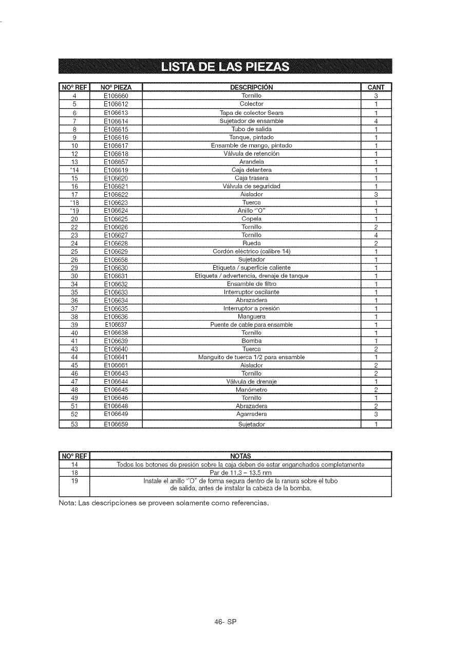
NO ° REF NO°PIEZA
4 E106660
5 E106612
6 E106613
7 E106614
8 E106615
9 E106616
10 E106617
12 E106618
13 E106657
"14 E106619
15 E106620
16 E106621
17 E106622
"18 E106623
"19 E106624
20 E106625
22 E106626
23 E106627
24 E106628
25 E106629
26 E106658
29 E106630
30 E106631
34 E106632
35 E106633
36 E106634
37 E106635
38 E106636
39 E106637
40 E106638
41 E106639
43 E106640
44 E106641
45 E106661
46 E106643
47 E106644
48 E106645
49 E106646
51 E106648
52 E106649
53 E106659
DESCRIPCION CANT
Tornillo 3
Colector 1
Tapa de colector Sears 1
Sujetador de ensamble 4
Tubo de salida 1
Tanque, pintado 1
Ensamble de mango, pintado 1
V&lvula de retencidn 1
Arandela 1
Caja delantera 1
Caja trasera 1
V&lvula de seguridad 1
Aislador 3
Tuerca 1
Anillo "O" 1
Copela 1
Tornillo 2
Tornillo 4
Rueda 2
Cord6n electrico (calibre 14) 1
Sujetador 1
Etiqueta /superficie caliente 1
Etiqueta /advertencia, drenaje de tanque 1
Ensamble de filtro 1
Interruptor oscilante 1
Abrazadera 1
Interruptor a presidn 1
Manguera 1
Puente de cable para ensamble 1
Tornillo 1
Bomba 1
Tuerca 2
Manguito de tuerca 1/2 para ensamble 1
Aislador 2
Tornillo 2
V_lvula de drenaje 1
Man6metro 2
Tornillo 1
Abrazadera 2
Agarradera 3
Sujetador 1
NO° REF
14
18
19
NOTAS
Todos los botones de presion sobre la caja deben de estar enganchados completamente
Parde 11.3- 13.5 nm
Instale el anillo "O" de forma segura dentro de la ranura sobre el tubo
de salida, antes de instalar la cabeza de la bomba.
Nora: Las descripciones se proveen solamente como referencias.
46- SP
Your Home
For expert troubleshooting and home solutions advice:
www.managemyhome.com
For repair - in your home - of all major brand appliances,
lawn and garden equipment, or heating and cooling systems,
no matter who made it, no matter who sold it !
For the replacement parts, accessories and
owner's manuals that you need to do-it-yourself.
For Sears professional installation of home appliances
and items like garage door openers and water heaters.
1-800-4-MY-HOME ®Call anytime, day or night
(1-800-469-4663) (U.S.A. and Canada)
www.sears.com www.sears.ca
Our Home
For repair of carry-in items like vacuums, lawn equipment,
and electronics, call anytime for the location of the nearest
Sears Parts & Repair Service Center
1-800-488-1222 (U.S.A.) 1-800-469-4663 (Canada)
www.sears.com www.sears.ca
To purchase a protection agreement on a product serviced by Sears:
1-800-827-6655 (u.sA.) 1-800-361-6665 (Canada)
Para pedir servicio de reparaci6n Au Canada pour service en frangais:
a domicilio, y para ordenar piezas: 1-800-LE-FOYER Mc
1-888-SU-HOGAR® (1-800-533-6937)
(1-888-784-6427) www.sears.ca
© Sears Brands, LLC
® Registered Trademark /TM Trademark /SMService Mark of Sears Brands, LLC
® Marca Registrada /TM Marca de Fabrica /SM Marca de Servicio de Sears Brands, LLC
MC Marque de commerce /MDMarque d6pos_e de Sears Brands, LLC
