Craftsman 93420105 User Manual WELDER Manuals And Guides L0803454
CRAFTSMAN Welder Manual L0803454 CRAFTSMAN Welder Owner's Manual, CRAFTSMAN Welder installation guides
User Manual: Craftsman 93420105 93420105 CRAFTSMAN WELDER - Manuals and Guides View the owners manual for your CRAFTSMAN WELDER #93420105. Home:Tool Parts:Craftsman Parts:Craftsman WELDER Manual
Open the PDF directly: View PDF ![]() .
.
Page Count: 36
. EAR$
OWNERS
MANUAL
MODEL No.
934.20105
CAUTION:
Read Rules for
Safe Operation
and Instructions
Carefully
811-309-000
MANUAL
WIRE FEED
MIG WELDER
Operation
Repair Parts
811-309-000
SEARS ROEBUCK AND CO., CHICAGO, IL 60684 U.S.A.
Table of Contents
IMPORTANT SAFETY INSTRUCTIONS 1
SHOCK HAZARDS ......................... 1
FLASH HAZARDS ......................... 2
FIRE HAZARDS ........................... 2
FUME HAZARDS .................... ...... 3
COMPRESSED GASSES AND EQUIPMENT HAZ-
ARDS ................................... 3
ADDITIONAL SAFETY INFORMATION ......... 4
PRODUCT DESCRIPTION 5
SPECIFICATIONS ......................... 5
WELDER CONTROLS AND THEIR FUNCTIONS. 5
DUTY CYCLE ............................. 5
INTERNAL THERMAL PROTECTION .......... 5
ASSEMBLY AND INSTALLATION 6
UNPACKING YOUR WELDER ................ 6
INSTALL THE GROUND CLAMP .............. 6
INSTALL WELDING GUN ASSEMBLY .......... 7
PROVIDE REQUIRED POWER ............... 7
Power Requirements ....................... 7
Connect Welder to Power Source ............. 8
Extension Cord Use ........................ 8
INSTALL TANK TRAY AND BRACKET .......... 8
SELECT SHIELDING GAS ................... 9
Gas Selection For Steel Welding With Steel Wire. 9
Gas Selection for Aluminum Welding .......... 9
Gas Selection for Stainless Steel Welding ...... 9
Gas Selection for Steel Welding
with Silicon-Bronze Wire .................... 10
INSTALL THE SHIELDING GAS ............... 10
CHECKING GAS FLOW ..................... 11
SELECT WELDING CURRENT POLARITY ...... 11
SELECT THE WELDING WIRE ............... 11
Selecting the Type of Wire ................... 11
SELECT THE SPOOL SIZE .................. 12
Wire Spool Storage ........................ 13
Select the Wire Diameter .................... 13
INSTALL THE WELDING WIRE ............... 13
Changing the Drive Roller ................... 13
INSTALLING ALUMINUM WIRE .............. 16
PREPARING TO WELD 17
PREPARING A SAFE WELDING WORK AREA.. 17
PREPARING THE WORK PIECE ............. 17
ALUMINUM WELDING PREPARATION ........ 18
CONNECT WELDER GROUND .............. 18
OPERATION 19
GETTING TO KNOW YOUR NEW WELDER .... 19
SETTING THE CONTROLS ................. 19
HOLDING THE GUN ....................... 20
Position of the Gun to the Work Piece ......... 20
Distance from the Work Piece ............... 21
LAYING A BEAD .......................... 21
CLEANING THE WELD BEAD ............... 21
WELDING TECHNIQUES 22
TRAVELING WITH THE GUN ................ 22
TYPES OF WELD BEADS .................. 22
WELDING POSITIONS ..................... 23
MULTIPLE PASS WELDING ................. 24
SPECIAL WELDING METHODS 25
SPOT WELDING .......................... 25
SPOT WELDING INSTRUCTIONS ............ 25
MAINTENANCE AND TROU-
BLESHOOTING 26
GENERAL MAINTENANCE ....... .......... 26
CONSUMABLE MAINTENANCE AND TROU-
BLESHOOTING .......................... 26
TESTING FOR A SHORTED NO72'LE ......... 27
TROUBLESHOOTING ...................... 27
REPLACEMENT PARTS LIST 33
WARRANTY 34
IMPORTANT SAFETY INSTRUCTIONS Page 1
IMPORTANT SAFETY INSTRUCTIONS
SAVE THESE INSTRUCTIONS! DO NOT OPERATE YOUR WELDER UNTIL
YOU HAVE READ AND UNDERSTAND THESE INSTRUCTIONS
(welding rod or welding wire). Any metal parts on
the electrode holder or MIG gun.
ELECTRIC SHOCK CAN KILL!
I_:_l ARC RAYS CAN INJURE EYES AND
BURN SKIN!
NEVER weld in a damp area or come in contact
with a moist or wet surface when welding.
NEVER attempt to weld if any part of clothing or
body is wet.
NEVER allow the welding equipment to come in
contact with water or moisture.
FIRE OR EXPLOSION CAN CAUSE
DEATH, INJURY, AND PROPERTY DAMAGE!
FUMES, GASSES, AND VAPORS CAN
CAUSE DISCOMFORT, ILLNESS, AND DEATH!
IMPROPER HANDLING AND MAIN-
TENANCE OF COMPRESSED GAS CYLIN-
DERS AND REGULATORS CAN RESULT IN
SERIOUS INJURY OR DEATH!
IMPORTANT! DO NOT ATTEMPT OPERATION
of this welding equipment until reading and under-
standing the following safety instructions to reduce
risk of DEATH, INJURY, AND PROPERTY DAM-
AGE.
SHOCK HAZARDS
ELECTRIC SHOCK CAN KILL! To reduce risk of
death from electric shock, read, understand, and
follow the following safety insructions. In Addition,
make certain that anyone who uses this welding
equipment or is a bystander in the welding area
understands and follows these safety instructions
as well.
NEVER Stand, Sit, Lie, Lean On, Touch, or come
into physical contact in any way with any part of the
welding current circuit including:
the work piece or any conductive material in con-
tact with it. The ground clamp. The electrode
NEVER drag welding cables (or MIG gun assem-
bly) or weld powercord through or allow them to
come into contact with water or moisture.
NEVER touch welder, attempt to turn welder on or
off, or attempt to plug welder into powersource if
any part of body or clothing is wet or damp, or if
standing in or in physical contact of any kind with
water or moisture.
NEVER connect welder ground clamp to or weld
on electrical conduit.
NEVER alter powercord or powercord plug in any
way.
NEVER attempt to plug welder into powersource if
ground prong on powercord plug is bent over,
broken off, or missing.
NEVER allow welder to be connected to power-
source or attempt to weld if welder, welding cables
(or MIG gun assembly), welding site, or welder
powercord are exposed to rain, snow, sleet, mist,
fog or other forms of atmospheric precipitation or
mist or spray off an ocean or other body of water.
NEVER carry coiled welding cables around shoul-
ders, or any other part of the body, when they are
plugged into the welder.
NEVER modify any wiring, ground connections,
switches, or fuses in this welding equipment.
ALWAYS wear welding gloves to help insulate
hands from welding circuit.
IMPORTANTSAFETYINSTRUCTIONSPage2
ALWAYSkeep containers of water or other liquids
far enough away from welder and work area so that
if spilled, the liquid could not possibly come in contact
with the welder, welding cables (or MIG gun assem-
bly), welder powercord, the workpiece being welded,
or any other part of the electrical welding circuit.
ALWAYS replace any cracked or damaged parts
that are insulated or act as insulators such as
welding cables (or MIG gun assembly), or power-
cord IMMEDIATELY.
FLASH HAZARDS
ARC RAYS CAN INJURE EYES AND BURN
SKIN! To reduce risk of injury from arc rays, read
understand and follow the following safety insrtuc-
tions. In addition, make certain that anyone else
that uses this welding equipment, or is a bystander
in the welding area, understands and follows these
safety instructions as well
NEVER look at an electric arc without proper pro-
tection. A welding arc is extremely bright and in-
tense and, with inadequate or no eye protection,
the retina can be burned, leaving a permanent
dark spot in the field of vision. A shield or helmet
with a number 10 shade filter lens (minimum) must
be used.
NEVER strike awelding arc until all bystanders
and you (the welder) have welding shields and/or
helmets in place.
NEVER wear acracked or broken helmet and
replace any cracked or broken filter lenses IMME-
DIATELY.
ALWAYS provide bystanders with shields or hel-
mets fitted with a number 10 shade filter lens.
ALWAYS wear protective clothing. The intense
light of the welding arc can bum the skin in much
the same way as the sun, even through light-
weight clothing. Wear dark clothing of heavy mate-
rial. The shirt worn should be long sleeved and the
collar kept buttoned to protect chest and neck.
ALWAYS protect against REFLECTED ARC
RAYS. Arc rays can be reflected off shiny surfaces
such as a glossy painted surface, aluminum, stain-
less steel, and glass. It is possible for your eyes to
be injured by reflected arc rays even when wearing
aprotective helmet or shield. If welding with a
reflective surface behind you, arc rays can
"bounce off" the surface, then off the filter tens on
the inside of your helmet or shield, then into your
eyes. If a reflective background exists in your weld-
ing area, either remove it or cover it with something
nonflammable and non-reflective. Reflective arc
rays can also cause skin burn in addition to eye
injury.
FIRE HAZARDS
FIRE OR EXPLOSION CAN CAUSE DEATH, IN-
JURY, AND PROPERTY DAMAGE! To reduce
risk of death, injury, or property damage from fire
or explosion, read, understand, and follow the fol-
lowing safety insrtuctions. In addition, make cer-
tain that anyone else that uses this welding
equipment, or is a bystander in the welding area,
understands and follows theses safety instructions
as well. REMEMBERI Arc welding by nature pro-
duces sparks, hot spatter, molten metal drops, hot
slag, and hot metal parts which can start fires, burn
skin and damage eyes.
NEVER wear gloves or other clothingthat contain
oil,grease, or other flammable substances.
NEVER wear flammable hair preparations.
NEVER weld in an area until it has been checked
and cleared of combustable and/or flammable ma-
terials. BE AWARE that sparks and slag can fly 35
feet and can pass through small cracks and open-
ings. If work and combustibles cannot be sepa-
rated by a minimum of 35 feet, protect against
ignition with suitable, snug-fitting, fire resistant
covers or shields.
NEVER weld on walls until checking for and remov-
ing combustibles touching the wall on the other side.
NEVER weld, cut, or perform other hot work on
used barrels, drums, tanks, or other containers
that contained a flammable or toxic substance.
The techniques for removing flammable sub-
stances and vapors, to make a used container safe
for welding or cutting, are quite complex and re-
quire special education and training.
NEVER strike an arc on a compressed gas or air
cylinder or other pressure vessel. Doing so will
create a brittle area that can result in a violent
rupture immediately or at a later time as a result of
rough handling.
NEVER weld or cut in an area where the air may
contain flammable dust (such as grain dust), gas,
or liquid vapors (such as gasoline).
NEVER handle hot metal, such as the workpiece
or welding wire, with bare hands.
ALWAYS wear leather gloves, heavy long sleeve
shirt, cuffless trousers, high-topped shoes, helmet,
and cap. As necessary, use additional protective
clothing such as leather jacket or sleeves, fire
resistant leggings, or apron. Hot sparks or metal
can lodge in rolled up sleeves, trouser cuffs, or
pockets. Sleeves and collars should be kept but-
toned and pockets eliminated from the front.
ALWAYS have fire extinguishing equipment handy
for instant use! A portable chemical fire extin-
quisher, type ABC, is recommended.
ALWAYS wear ear plugs when welding overhead
to prevent spatter or stag from falling into ear.
ALWAYS make sure welding area has agood,
solid, safe floor, preferably concrete or masonry,
not tiled, carpeted, or made of anyother flammable
material.
ALWAYS protect flammable walls, ceilings, and
floors with heat resistant covers or shields.
ALWAYS check welding area to make sure it is
free of sparks, glowing metal or slag, and flames
before leaving the welding area.
FUME HAZARDS
FUMES, GASSES, AND VAPORS CAN CAUSE
DISCOMFORT, ILLNESS, AND DEATH! To re-
duce risk of discomfort, illness, or death, read,
understand, and follow the following safety instruc-
tions. In addition, make certain that anyone else
that uses this welding equipment or is a bystander
in the welding area, understands and follows these
safety instructions as well.
NEVER weld in an area until it has been checked
for adequate ventilation as described in ANSI
standard #Z49.1. If ventilation is not adequate to
exchange all fumes and gasses generated during
the welding process with fresh air, do not weld
unless you (the welder) and all bystanders are
wearing air-supplied respirators.
NEVER heat metals coated with or containing ma-
terials that produce toxic fumes, such as galva-
IMPORTANT SAFETY INSTRUCTIONS Page)3
nized steel, unless the coating is removed, the
area is well ventilated, or the operator and _all'
bystanders wear air-supplied respirators.
NEVER weld, cut, or heat lead, zinc, cadmium,
mercury, beryllium, or similar metals without seek-
ing professional advise and inspection of the ven-
tilation of the welding area. These metals produce
EXTREMELY TOXIC fumes which can cause dis-
comfort, illness, and death.
NEVER weld or cut in areas that are near chlorin-
ated solvents. Vapors from chlorinated hydrocar-
bons, such as trichlorbethylene and
perchloroethylene, can be decomposed by the
heat of an electric arc or its ultraviolet radiation to
form PHOSGENE, a HIGHLY TOXIC gas, along
with other lung and eye-irritating gasses. Do not
weld or cut where these solvent vapors can be
drawn into the work area or where the ultraviolet
radiation can penetrate to areas containing even
very small amounts of these vapors.
NEVER weld in aconfined area unless it is being
ventilated or the operator (and anyone else in the
area) is wearing an air-supplied respirator.
NEVER bring gas cylinders into or allow gas leaks
in a confined space. Leaked gas can rapidly re-
duce oxygen concentration levels in a confined
space.
ALWAYS shut off shielding gas supply at its source
before leaving a confined area and check to make
sure that the area is safe before reentering it.
ALWAYS stop welding if you develop momentary
eye, nose, or throat irritation as this indicates in-
adequate ventilation. Stop work and take neces-
sary steps to improve ventilation in the welding
area. Do not resume welding if physical discomfort
persists.
COMPRESSED GASSES AND
EQUIPMENT HAZARDS
IMPROPER HANDLING AND MAINTENANCE
OF COMPRESSED GAS CYLINDERS AND
REGULATORS CAN RESULT IN SERIOUS IN-
JURY OR DEATH! To reduce risk or injury or death
from compressed gasses and equipment hazards,
read, understand, and follow the following safety
instructions. In addition, make certain that anyone
else who uses this welding equipment or is a
bystander in the welding area understands and
follows these safety instructions as well.
IMPORTANT SAFETY INSTRUCTIONS Page 4
NEVER use flammable gasses with MIG welders.
Only inert or non-flammable gasses are suitable
for MIG welding. Examples are Carbon Dioxide,
Argon, Helium, etc. or mixtures of more than one
of these gasses.
NEVER attempt to mix gasses or refill a cylinder
yourself.
NEVER expose cylinders to excessive heat,
sparks, slag, and flame, etc. Cylinders exposed to
temperatures above 130 degrees F. will require
water spray cooling.
NEVER expose cylinders to electricity of any kind.
NEVER use cylinder or its contents for anything
other than its intended use. Do not use as a sup-
port or roller.
NEVER locate cylinders in passageways or work
areas where they may be struck.
NEVER lift cylinders off the ground by their valves
or caps or with chains, slings, or magnets.
NEVER use a wrench or hammer to open a cylin-
der valve that cannot be opened by hand. Notify
your supplier.
NEVER modify or exchange gas cylinder fittings.
NEVER deface or altar name, number, or other
markings on a cylinder. It is illegal and hazardous.
NEVER use cylinders without the name of the gas
marked on the cylinder. Do not rely on cylinder
color to identify the content.
NEVER connect a regulator to a cylinder contain-
ing gas other than that for which the regulator was
designed.
NEVER attempt to make regulator repairs. Send
faulty regulators for repair to manufacturer's des-
ignated repair center.
NEVER attempt to lubricate regulator.
ALWAYS handle cylinders carefully to prevent
leaks and damage to their wails, valves, or safety
devices.
ALWAYS secure cylinders with a steel chain so
that they cannot be knocked over.
ALWAYS protect cylinder, especially valve, from
bumps, falls, falling objects, and weather.
ALWAYS make sure cylinder cap is securely in
place, on the cylinder, whenever cylinder is moved.
ALWAYS remove faulty regulator from service im-
mediately for repair (first close cylinder valve) if
any of the following occur: Gas leaks extemally,
delivery pressure continues to rise with down
stream valve closed, and/or gauge pointer does
not move off the stop pin when pressurized or fails
to return to the stop pin after pressure is released.
ADDITIONAL SAFETY
INFORMATION
For additional information concerning welding
safety, refer to the following standards and comply
with as applicable.
1. ANSI Standard Z49.1 -- SAFETY IN WELDING
AND CUTTING ---obtainable from the American
Welding Society, 2051 N.W. 7th St., Miami, FL
33125 Telephone (305) 443-9353
2. ANSI Standard Z87.1 -- SAFE PRACTICE
FOR OCCUPATION AND EDUCATIONAL EYE
AND FACE PROTECTION -- obtainable from
the American National Standards Institute, 1430
Broadway, New York, NY 10018
3. NFPA Standard 51B -- CUTTING AND WELD-
ING PROCESSES -- obtainable from the Na-
tional Fire Protection Association, 470 Atlantic
Ave., Boston, MA 02210
4. CGA Pamphlet P-1 --SAFE HANDLING OF
COMPRESSED GASSES IN CYLINDERS
obtainable from the Compressed Gas Associa-
tion, 500 5th Ave., New York, NY 10036
5. OSHA Standard 29 CFR, Part 1910, Subpart Q,
WELDING, CU'I-I'ING AND BRAZING -- ob-
tainable from your state OSHA office.
6. CSA Standard W177.2 -- Code for SAFETY IN
WELDING AND CUTTING -- obtainable from
Canadian Standards Association, 178 Rexdale
Blvd., Rexdate, Ontario, Canada M9W 1R3
PRODUCT DESCRIPTION Page. 5
PRODUCT DESCRIPTION
Your new Metal Inert Gas (MIG) wire feed welder
is designed for maintenance, and sheetmetal fab-
rication. The welder consists of asingle-phase
power transformer, stabilizer, rectifier, and a
unique built-in control/feeder. This MIG welder is
capable of welding with .024" and .030" solid steel,
or stainless steel wires and .030" aluminum (spec
#5356 alloy) wire on DC positive polarity and with
.030", self-shielding flux-core wire on DC negative
polarity.
WIRE SPEED - This control adjusts the speed at
which the wire is fed out of the gun. The wire speed
needs to be closely matched ("tuned-in") to the
rate at which it is being melted off. Some things
that affect wire speed selection are the type and
diameter of the wire being used, the heat setting
selected, and the welding position to be used.
DUTY CYCLE
NOTE; When using .035 Flux Core wire your duty
cycle may be shorter than 20%.
Now you can weld 20 gauge sheet metal up to
3/16" with a single pass. Welds 114" steel with
beveling and multiple pass.
SPECIFICATIONS
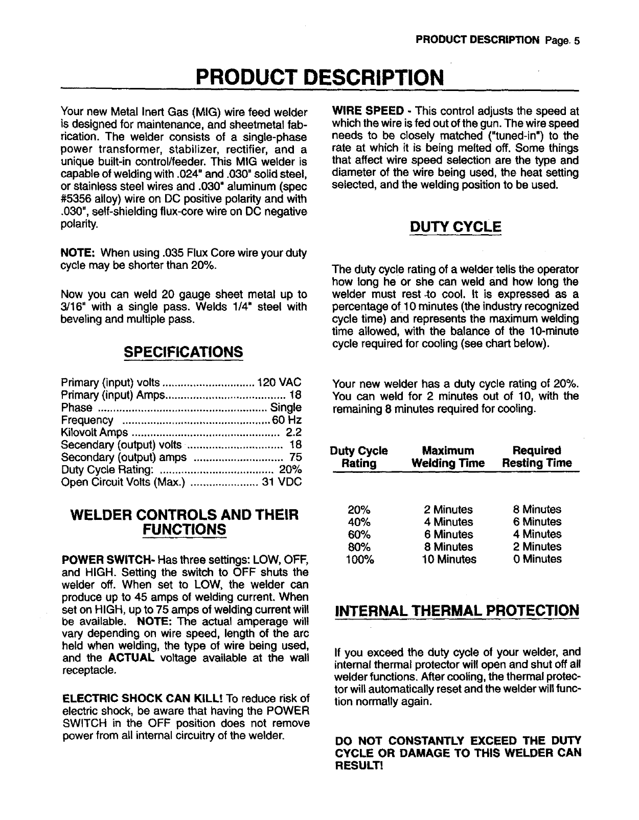
The duty cycle rating of a welder tells the operator
how long he or she can weld and how long the
welder must rest-to cool. tt is expressed as a
percentage of 10 minutes (the industry recognized
cycle time) and represents the maximum welding
time allowed, with the balance of the 10-minute
cycle required for cooling (see chart below).
Primary (input) volts .............................. 120 VAC
Primary (input) Amps ....................................... 18
Phase ....................................................... Single
Frequency ................................................ 60 Hz
Kilovolt Amps ................................................ 2.2
Secendary (output) volts ............................... 18
Secondary (output) amps ............................. 75
Duty Cycle Rating: ..................................... 20%
Open Circuit Volts (Max.) ...................... 31 VDC
WELDER CONTROLS AND THEIR
FUNCTIONS
POWER SWITCH- Has three settings: LOW, OFF,
and HIGH. Setting the switch to OFF shuts the
welder off. When set to LOW, the welder can
produce up to 45 amps of welding current. When
set on HIGH, up to 75 amps of welding current will
be available. NOTE: The actual amperage will
vary depending on wire speed, length of the arc
held when welding, the type of wire being used,
and the ACTUAL voltage available at the wall
receptacle.
ELECTRIC SHOCK CAN KILL! To reduce risk of
electric shock, be aware that having the POWER
SWITCH in the OFF position does not remove
power from all intemal circuitry of the welder.
Your new welder has a duty cycle rating of 20%.
You can weld for 2 minutes out of 10, with the
remaining 8 minutes required for cooling.
Duty Cycle
Rating
Maximum Required
Welding Time Resting Time
20% 2Minutes 8 Minutes
40% 4 Minutes 6 Minutes
60% 6 Minutes 4 Minutes
80% 8 Minutes 2 Minutes
100% 10 Minutes 0 Minutes
INTERNAL THERMAL PROTECTION
If you exceed the duty cycle of your welder, and
internal thermal protector will open and shut off ai!
welder functions. After cooling, the thermal protec-
tor will automatically reset and the welder wilt func-
tion normally again.
DO NOT CONSTANTLY EXCEED THE DUTY
CYCLE OR DAMAGE TO THIS WELDER CAN
RESULT!
ASSEMBLYANDINSTALLATIONPage6
ASSEMBLY AND INSTALLATION
ELECTRIC SHOCK CAN KILL! To re-
duce risk of electric shock, DO NOT PLUG
WELDER IN TO AC POWER SOURCE UNTIL
TOLD TO DO SO later in this manual.
UNPACKING YOUR WELDER
1. Open the top of the shipping carton.
2. Remove any cartons or bags containing acces-
sories.
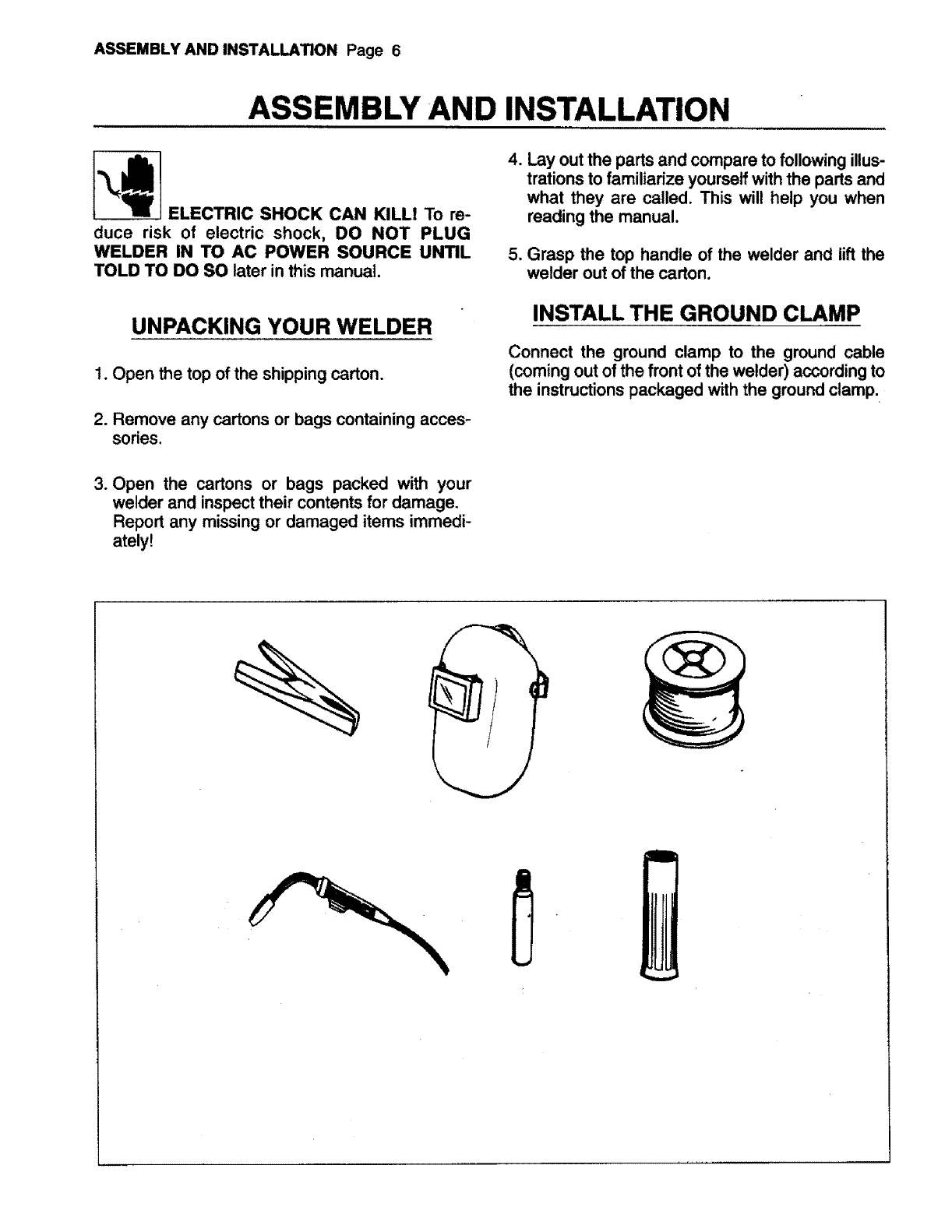
4. Lay out the parts and compare tofollowing illus-
trations to familiarize yourself with the parts and
what they are called. This will help you when
reading the manual.
5. Grasp the top handle of the welder and lift the
welder out of the carton.
INSTALL THE GROUND CLAMP
Connect the ground clamp to the ground cable
(coming out of the front of the welder) according to
the instructions packaged with the ground clamp.
3. Open the cartons or bags packed with your
welder and inspecttheir contents for damage.
Report any missing or damaged items immedi-
ately!
ASSEMBLY AND INSTALLATION Page 7
O
OO
000
0 0
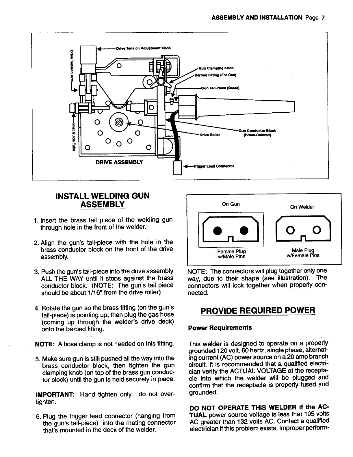
DRIVE ASSEMBLY
Knob
INSTALL WELDING GUN
ASSEMBLY
1. Insert the brass tail piece of the welding gun
through hole in the front of the welder.
2. Align the gun's tail-piece with the hole in the
brass conductor block on the front of the drive
assembly.
3, Push the gun's tail-piece into the drive assembly
ALL THE WAY until it stops against the brass
conductor block. (NOTE: The gun's tail piece
should be about 1/16" from the drive roller)
4. Rotate the gun so the brass fitting (on the gun's
tail-piece) is pointing up, then plug the gas hose
(coming up through the welder's drive deck)
onto the barbed fitting.
NOTE: Ahose clamp is not needed on this fitting.
5. Make sure gun is still pushed all the way into the
brass conductor block, then tighten the gun
clamping knob (on top of the brass gun conduc-
tor block) until the gun is held securely in place.
IMPORTANT: Hand tighten only. do not over-
tighten.
6. Plug the trigger lead connector (hanging from
the gun's tail-piece) into the mating connector
that's mounted in the deck of the welder.
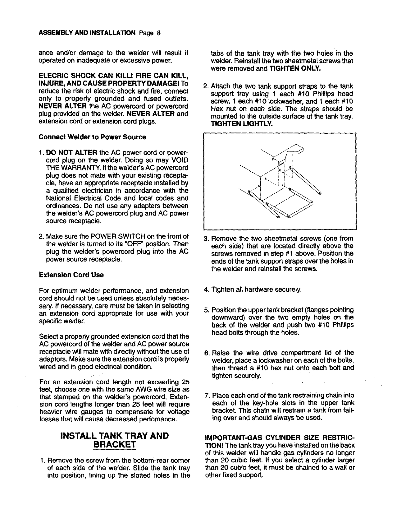
On Gun
Female Plug
w/Male Pins
On Welder
NOTE: The connectors will plug together only one
way, due to their shape (see illustration). The
connectors will lock together when properly con-
nected.
PROVIDE REQUIRED POWER
Power Requirements
This welder is designed to operate on a properly
grounded 120 volt, 60 hertz, single phase, alternat-
ing current (AC) power source on a 20 amp branch
circuit. It is recommended that a qualified electri-
cian verify the ACTUAL VOLTAGE at the recepta-
cle into which the welder will be plugged and
confirm that the receptacle is properly fused and
grounded.
DO NOT OPERATE THIS WELDER if the AC-
TUAL power source voltage is less that 105 volts
AC greater than 132 volts AC. Contact a qualified
electrician if this problem exists. Improper perform-
ASSEMBLY AND INSTALLATION Page 8
ance and/or damage to the welder will result if
operated on inadequate or excessive power.
ELECRIC SHOCK CAN KILL! FIRE CAN KILL,
INJURE, AND CAUSE PROPERTY DAMAGE! To
reduce the risk of electric shock and fire, connect
only to properly grounded and fused outlets.
NEVER ALTER the AC powercord or powercord
plug provided on the welder. NEVER ALTER and
extension cord or extension cord plugs.
Connect Welder to Power Source
1, DO NOT ALTER the AC power cord or power-
cord plug on the welder. Doing so may VOID
THE WARRANTY. If the welder's AC powercord
plug does not mate with your existing recepta-
cle, have an appropriate receptacle installed by
a qualified electrician in accordance with the
National Electrical Code and local codes and
ordinances. Do not use any adapters between
the welder's AC powercord plug and AC power
source receptacle.
2. Make sure the POWER SWITCH on the front of
the welder is turned to its "OFF" position. Then
plug the welder's powercord plug into the AC
power source receptacle.
Extension Cord Use
For optimum welder performance, and extension
cord should not be used unless absolutely neces-
san/. If necessary, care must be taken in selecting
an extension cord appropriate for use with your
specific welder.
Select aproperty grounded extension cord that the
AC powercord of the welder and AC power source
receptacle will mate with directly without the use of
adaptors. Make sure the extension cord is properly
wired and in good electrical condition.
For an extension cord length not exceeding 25
feet, choose one with the same AWG wire size as
that stamped on the welder's powercord, Exten-
sion cord lengths longer than 25 feet will require
heavier wire gauges to compensate for voltage
losses that will cause decreased perfomance.
INSTALL TANK TRAY AND
BRACKET
1. Remove the screw from the bottom-rear comer
of each side of the welder. Slide the tank tray
into position, lining up the slotted holes in the
tabs of the tank tray with the two holes in the
welder. Reinstall the two sheetmetal screws that
were removed and TIGHTEN ONLY.
.Attach the two tank support straps to the tank
support tray using 1each #10 Phillips head
screw, 1 each #10 Iockwasher, and 1 each #10
Hex nut on each side. The straps should be
mounted to the outside surface of the tank tray.
TIGHTEN LIGHTLY.
3, Remove the two sheetmetal screws (one from
each side) that are located directly above the
screws removed in step #1 above. Position the
ends of the tank support straps over the holes in
the welder and reinstall the screws.
4. Tighten all hardware securely.
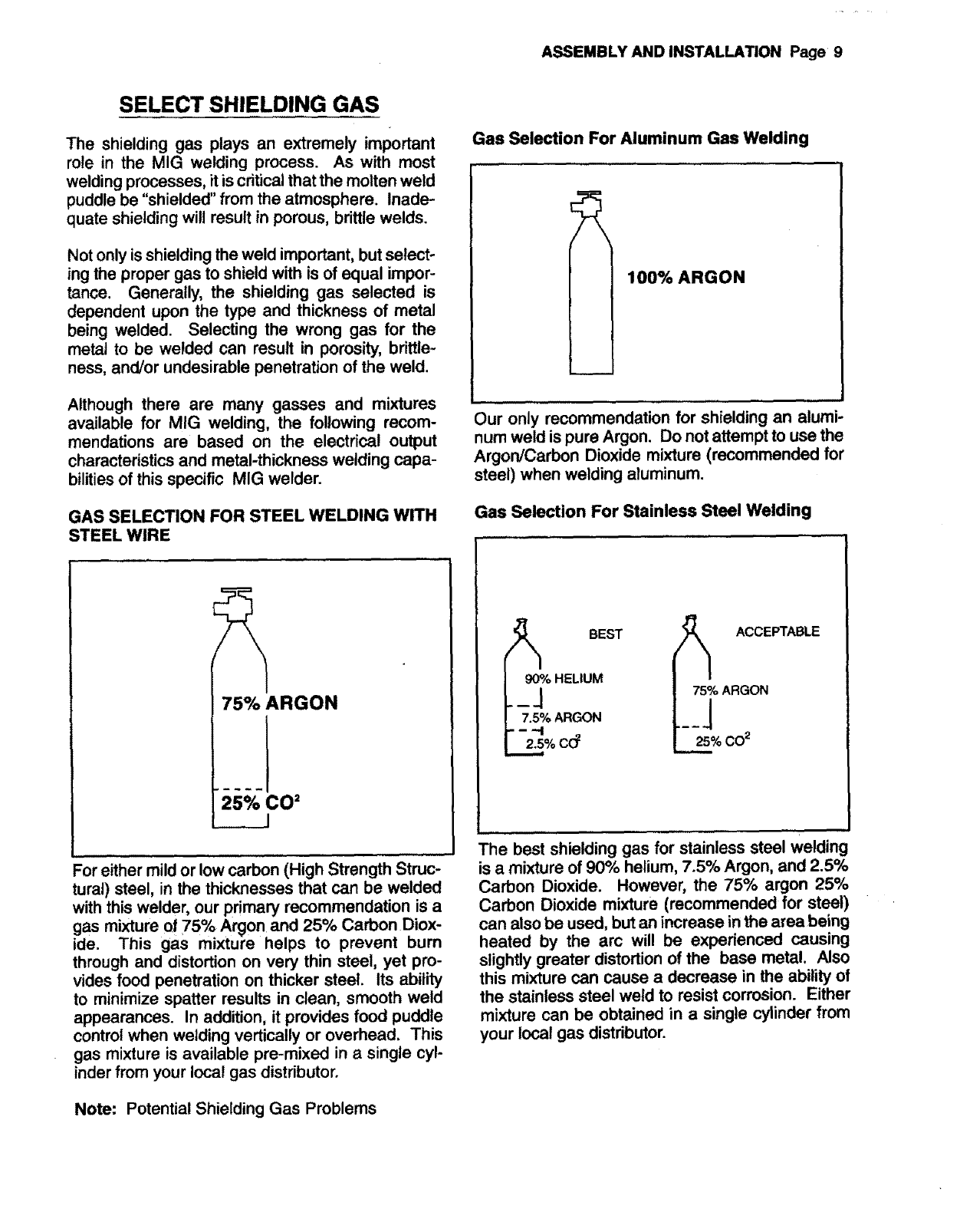
.Position the upper tank bracket (flanges pointing
downward) over the two empty holes on the
back of the welder and push two #10 Phillips
head bolts through the holes.
6. Raise the wire drive compartment lid of the
welder, place a Iockwasher on each of the bolts,
then thread a #10 hex nut onto each bolt and
tighten securely.
7, Place each end of the tank restraining chain into
each of the key-hole slots in the upper tank
bracket. This chain will restrain a tank from fall-
ing over and should always be used.
IMPORTANT-GAS CYUNDER SIZE RESTRIC-
TION! The tank tray you have installed on the back
of this welder will handle gas cylinders no longer
than 20 cubic feet. If you select acylinder larger
than 20 cubic feet, it must be chained to a wall or
other fixed support.
ASSEMBLYANDINSTALLATIONPage9
SELECT SHIELDING GAS
The shielding gas plays an extremely important
role in the MIG welding process. As with most
welding processes, it is critical that the molten weld
puddle be "shielded" from the atmosphere. Inade-
quate shielding will result in porous, brittle welds.
Notonly is shieldingthe weld important, but select-
ing the proper gas to shield with isof equal impor-
tance. Generally, the shielding gas selected is
dependent upon the type and thickness of metal
being welded. Selecting the wrong gas for the
metal to be welded can result in porosity, brittle-
ness, and/or undesirable penetration of the weld.
Although there are many gasses and mixtures
available for MIG welding, the following recom-
mendations are based on the electrical output
characteristicsand metal-thickness welding capa-
bilitiesof this specific MIG welder.
GAS SELECTION FOR STEEL WELDING WITH
STEEL WIRE
Gas Selection For Aluminum Gas Welding
100% ARGON
Our only recommendation for shielding an alumP
num weld is pure Argon. Do not attempt to use the
Argon/Carbon Dioxide mixture (recommended for
steel) when welding aluminum.
Gas Selection For Stainless Steel Welding
75% ARGON
25% CO=
_J
For either mild or low carbon (High Strength Struc-
tural) steel, in the thicknesses that can be welded
with this welder, our primary recommendation is a
gas mixture of 75% Argon and 25% Carbon Diox-
ide. This gas mixture helps to prevent burn
through and distortion on very thin steel, yet pro-
vides food penetration on thicker steel. Its ability
to minimize spatter results in clean, smooth weld
appearances. In addition, it provides food puddle
control when welding vertically or overhead. This
gas mixture is available pre-mixed in asingle cyl-
inder from your local gas distributor.
_o/o BEST
HELIUM
F"_"_''%ARGON
_% c(:f
_o/, ° ACCEPTABLE
ARGON
r- -2_% co 2
The best shielding gas for stainless steel welding
is a mixture of 90% helium, 7.5% Argon, and 2.5%
Carbon Dioxide. However, the 75% argon 25%
Carbon Dioxide mixture (recommended for steel)
can also be used, but an increase in the area being
heated by the arc will be experienced causing
slightly greater distortion of the base metal. Also
this mixture can cause a decrease in the ability of
the stainless steel weld to resist corrosion. Either
mixture can be obtained in a single cylinder from
your local gas distributor.
Note: Potential Shielding Gas Problems
ASSEMBLYANDINSTALLATIONPage 10
Gas Selection For Steel Welding With Silicon-
bronze Wire
100% ARGON
Use only pure Argon when welding steel with Sili-
con-Bronze wire.
1. DEFECTIVE GAS -- Just like any other prod-
uct, a cylinder of gas can be defective. Moisture
or other impurities in the gas can create dirty
porous, brittle welds with greatly reduced pene-
tration. The only remedy is to replace the cylin-
der.
2. MIXTURE COMPOSITION CHANGE -- This
problem concerns only cylinders that contain a
mixture of two or more gasses. The mixture
composition in acylinder can be changed if the
cylinder is stored in cold temperatures. For the
75% Argon 25% Carbon Dioxide mixture, the
cylinder should not be stored below 40 degrees
R This information is normally found on the
label on the cylinder that indicates the contents
of the cylinder.
This problem can create a variety of unfavorable
weld characteristicsincluding porosity,brittles, and
improper penetration.
3. INSUFFICIENT SHIELDING GAS COVER-
AGE-- This problem can be created by several
causes as listed in the TROUBLESHOOTING
section of this manual. The symptoms are the
same for al! of them; dirty, porous, brittle, and/or
non-penetrating welds.
INSTALL THE SHIELDING GAS
IMPROPER HANDLING AND MAINTENANCE
OF COMPRESSED GAS CYLINDERS AND
REGULATORS CAN RESULT IN SERIOUS IN-
JURY OR DEATHI Always secure gas cylinders to
the tank bracket kit, a wall, or other fixed support
to prevent the cylinder from falling over and ruptur-
ing. Read, understand, and follow alt the COM-
PRESSED GASSES AND EQUIPMENT HAZ-
ARDS in the SAFETY INSTRUCTION section of
this manual.
1. Secure gas cylinder to the tank bracket kit, a
wall or other fixed support.
2. Remove the protective cap from the cylinder
and inspect the regulator connecting threads for
dust, dirt, oil, and grease. Remove any dust or
dirt with a clean cloth. DO NOT ATTACH THE
REGULATOR IF OIL, GREASE, OR DAMAGE
ARE PRESENT.
.Open the cylinder valve FOR JUST AN IN-
STANT to blow out any foreign matter inside the
valve port to reduce the risk of plugging or dam-
aging the regulator. NEVER AIM THE CYLIN-
DER VALVE PORT AT YOURSELF OR ANY
BYSTANDERS WHEN OPENING CYLINDER
TO REDUCE THE RISK OF PERSONAL IN-
JURY.
4. Screw the regulator into the cylinder valve and
tighten with a wrench while keeping gauges
upright for easy and accurate reading.
NOTE: If the cylinder you have is equipped with
male regulator connecting threads instead of fe-
male, you wilt need to obtain a special compressed
gas cylinder adapter from your gas supplier to
install between your gas cylinder and regulator.
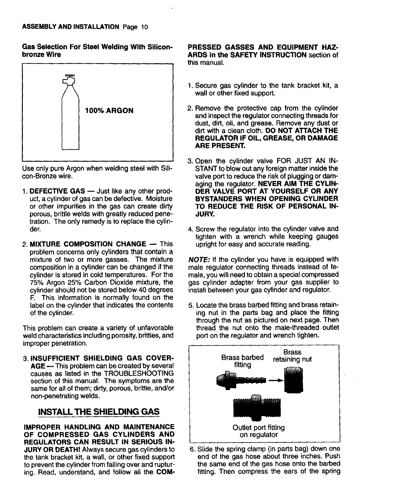
5. Locate the brass barbed fitting and brass retain-
ing nut in the parts bag and place the fitting
through the nut as pictured on next page. Then
thread the nut onto the male-threaded outlet
port on the regulator and wrench tighten.
Brass
Brass barbed retaining nut
fitting
Outlet port fitting
on regulator
6. Slide the spring clamp (in parts bag) down one
end of the gas hose about three inches. Push
the same end of the gas hose onto the barbed
fitting. Then compress the ears of the spring
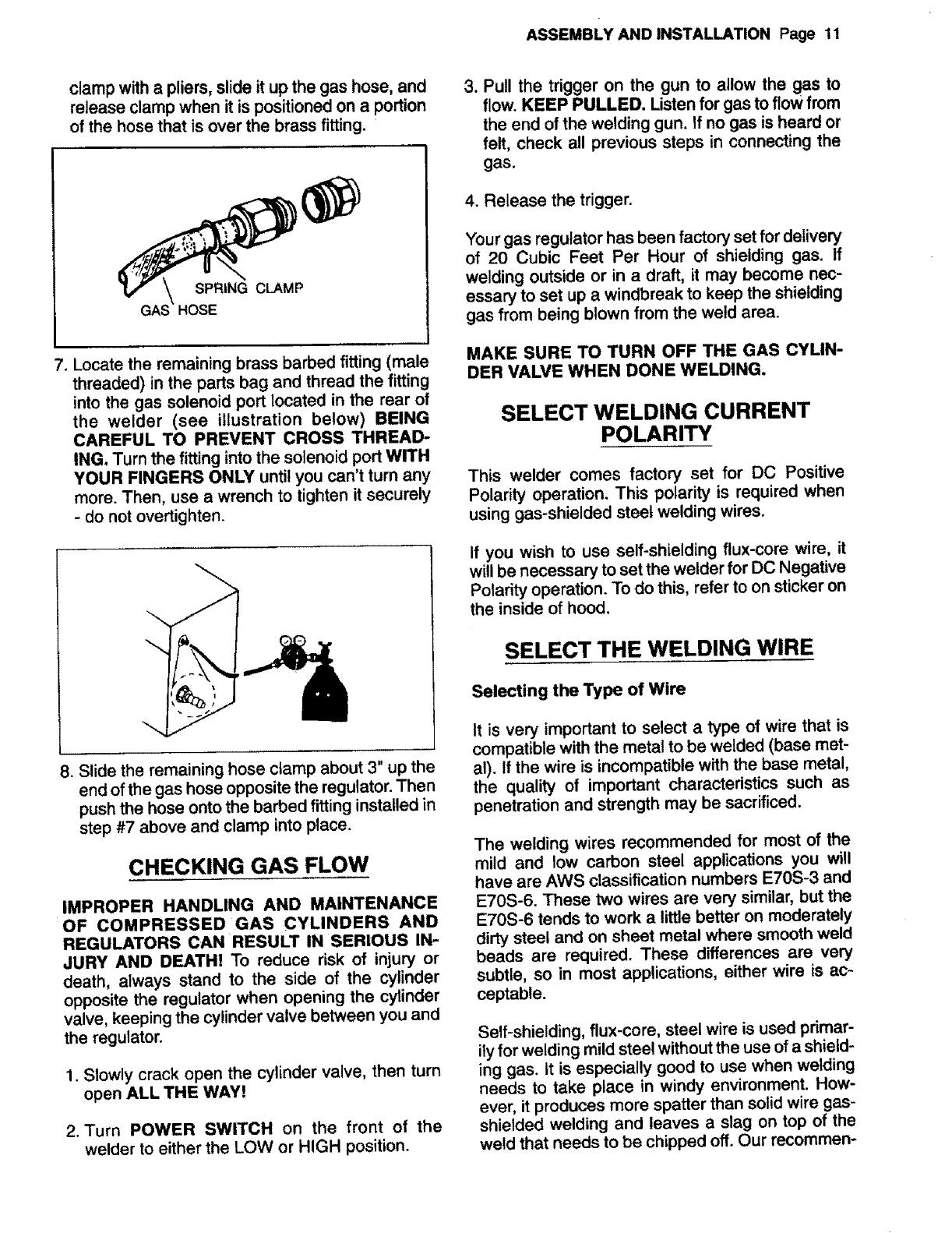
clamp witha pliers, slide it up the gas hose, and
release clamp when it is positioned on aportion
of the hose that is over the brass fitting. '
SPRING CLAMP
HOSE
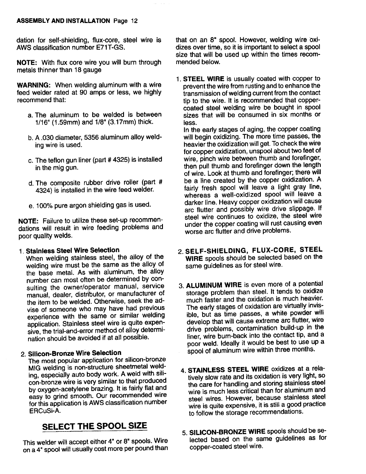
7. Locate the remaining brass barbed fitting (male
threaded) in the parts bag and thread the fitting
into the gas solenoid port located in the rear of
the welder (see illustration below) BEING
CAREFUL TO PREVENT CROSS THREAD-
ING. Turn the fitting into the solenoid port WITH
YOUR FINGERS ONLY until you can't turn any
more. Then, use a wrench to tighten it securely
-do not overtighten.
8. Slide the remaining hose clamp about 3" up the
end of the gas hose opposite the regulator. Then
push the hose onto the barbed fitting installed in
step #7 above and clamp into place.
CHECKING GAS FLOW
IMPROPER HANDLING AND MAINTENANCE
OF COMPRESSED GAS CYLINDERS AND
REGULATORS CAN RESULT IN SERIOUS IN-
JURY AND DEATH! To reduce risk of injury or
death, always stand to the side of the cylinder
opposite the regulator when opening the cylinder
valve, keeping the cylinder valve between you and
the regulator.
1. Slowly crack open the cylinder valve, then turn
open ALL THE WAY!
2. Turn POWER SWITCH on the front of the
welder to either the LOW or HIGH position.
ASSEMBLY AND INSTALLATION Page 11
3. Pull the trigger on the gun to allow the gas to
flow. KEEP PULLED. Listen for gas to flow from
the end of the welding gun. If no gas is heard or
felt, check all previous steps in connecting the
gas.
4. Release the trigger.
Your gas regulator has been factory set for delivery
of 20 Cubic Feet Per Hour of shielding gas. If
welding outside or in a draft, it may become nec-
essary to set up a windbreak to keep the shielding
gas from being blown from the weld area.
MAKE SURE TO TURN OFF THE GAS CYUN-
DER VALVE WHEN DONE WELDING.
SELECT WELDING CURRENT
POLARITY
This welder comes factory set for DC Positive
Polarity operation. This polarity is required when
using gas-shielded steel welding wires.
If you wish to use self-shielding flux-core wire, it
will be necessary to set the welder for DC Negative
Polarity operation. To do this, refer to on sticker on
the inside of hood.
SELECT THE WELDING WIRE
Selecting the Type of Wire
It is very important to select a type of wire that is
compatible with the metal to be welded (base met-
al). If the wire is incompatible with the base metal,
the quality of important characteristics such as
penetration and strength may be sacrificed.
The welding wires recommended for most of the
mild and low carbon steel applications you will
have are AWS classification numbers E70S-3 and
E70S-6. These two wires are very similar, but the
E70S-6 tends to work a little better on moderately
dirty steel and on sheet metal where smooth weld
beads are required. These differences are very
subtle, so in most applications, either wire is ac-
ceptable.
Self-shielding, flux-core, steel wire is used primar-
ily for welding mild steel without the use of a shield-
ing gas. It is especially good to use when welding
needs to take place in windy environment. How-
ever, it produces more spatter than solid wire gas-
shielded welding and leaves a slag on top of the
weld that needs to be chipped off. Our recommen-
ASSEMBLY AND INSTALLATION Page 12
dation for self-shielding, flux-core, steel wire is
AWS classification number E71T-GS.
NOTE: With flux core wire you will bum through
metats thinner than 18 gauge
WARNING: When welding aluminum with a wire
feed welder rated at 90 amps or less, we highly
recommend that:
a. The aluminum to be welded is between
t/16" (t .59mm) and 1/8" (3.17mm) thick.
b. A .030 diameter, 5356 aluminum alloy weld-
ing wire is used.
c. The teflon gun liner (part # 4325) is installed
in the mig gun.
d. The composite rubber drive roller (part #
4324) is installed inthe wire feed welder.
e. 100% pure argon shielding gas is used.
NOTE: Failure to utilize these set-up recommen-
dations will result in wire feeding problems and
poor quality welds.
1. Stainless Steel Wire Selection
When welding stainless steel, the alloy of the
welding wire must be the same as the alloy of
the base metal. As with aluminum, the alloy
number can most often be determined by con-
suiting the owner/operator manual, service
manual, dealer, distributor, or manufacturer of
the item to be welded. Otherwise, seek the ad-
vise of someone who may have had previous
experience with the same or similar welding
application. Stainless steel wire is quite expen-
sive, the trial-and-error method of alloy determi-
nation should be avoided if at all possible.
2. Silicon'Bronze Wire Selection
The most popular application for silicon-bronze
MIG welding is non-structure sheetmetal weld-
ing, especially auto body work. A weld with sili-
con-bronze wire is very similar to that produced
by oxygen-acetylene brazing. It is fairly flat and
easy to grind smooth. Our recommended wire
for this application is AWS classification number
ERCuSi-A.
SELECT THE SPOOL SIZE
This welder will accept either 4" or 8" spools. Wire
on a 4" spool wilt usually cost more per pound than
that on an 8" spool. However, welding wire oxi-
dizes over time, so it is important to select aspool
size that will be used up within the times recom-
mended below.
.STEEL WIRE is usually coated with copper to
prevent the wire from rusting and to enhance the
transmission of welding current from the contact
tip to the wire. It is recommended that copper-
coated steel welding wire be bought in spool
sizes that will be consumed in six months or
tess.
In the early stages of aging, the copper coating
will begin oxidizing. The more time passes, the
heavier the oxidization will get. To check the wire
for copper oxidization, unspool about two feet of
wire, pinch wire between thumb and forefinger,
then pull thumb and forefinger down the length
of wire. Look at thumb and forefinger; there will
be a line created by the copper oxidization. A
fairly fresh spool will leave a light gray line,
whereas a well-oxidized spool will leave a
darker line. Heavy copper oxidization will cause
arc flutter and possibly wire drive slippage. If
steel wire continues to oxidize, the steel wire
under the copper coating will rust causing even
worse arc flutter and drive problems.
2. SELF-SHIELDING, FLUX-CORE, STEEL
WIRE spools should be selected based on the
same guidelines as for steel wire.
.ALUMINUM WIRE is even more of a potential
storage problem than steel. It tends to oxidize
much faster and the oxidation is much heavier.
The early stages of oxidation are virtually invis-
ible, but as time passes, a white powder will
develop that will cause extreme arc flutter, wire
drive problems, contamination build-up in the
liner, wire burn-back into the contact tip, and a
poor weld. ideally it would be best to use up a
spool of aluminum wire within three months.
1STAINLESS STEEL WIRE oxidizes at arela-
tively slow rate and its oxidation is very light, so
the care for handling and storing stainless steel
wire is much less cdtical than for aluminum and
steel wires. However, because stainless steel
wire is quite expensive, it is still agood practice
to fotlow the storage recommendations.
5. SILICON-BRONZE WIRE spools should be se-
lected based on the same guidelines as for
copper-coated steel wire.
ASSEMBLYANDINSTALLATIONPage19
WireSpool Storage
The above recommended spool storage times are
rules-of-thumb and can be impacted by many fac-
tors such as length of time in distribution prior to
retail sale, warehouse conditions, time of year (ie:
Humid months or dry months), and how packaged
by the manufacturer.
Although these factors are out of your control,
there are some things that you can do to slow
down the oxidization process: store in a dry place
when not in use; store in sealed plastic bag when
not in use and leave unopened in the manufac-
turer's package until ready to use.
NOTE: If spool has developed heavy oxidation, the
only solution to the problem is to discard the spool
of wire. However, if you have an oxidized spool of
wire, do not discard it until trying the following:
unspool a few turns of wire to see if the wire further
down on the spool is in usable condition, if not --
discard the spool.
SELECT THE WIRE DIAMETER
t. Steel and Stainless Steel Welding
Base Metal Wire
Thickness Diameter
20 Gauge to 1/8" Gauge
18 Gauge to 1/8"
.024" (.6mm)
.030" (.8mm)
2. Aluminum Welding
Base Metal Wire
Thickness Diameter
i i
1/16"to 1/8" .030" (.8ram)
3. Silicon-Bronze Wire Welding of Steel
To be used for welding non-structural sheet-
metal to sheetmetal or non-structural sheet-
metal to heavier steel. Use .030" (.8mm)
diameter wire for these applications.
4. Steel welding with Self-Shielding Flux-Core
Wire
Your welder can use only .30 Flux-Core wire
AWS #E71T-GS,
Base Metal Wire
Thickness Diameter
i i
INSTALL THE WELDING WIRE
ELECTRIC SHOCK CAN KILL! Always turn the
POWER SWITCH to its OFF position and unplug
the welder's powercord from the AC power source
before installing wire.
1. Remove the nozzle and contact tip from the end
of the gun assembly.
2. Unscrew (turn counter-clockwise) the tension
adjusting screw ALL THE WAY.
3. Make sure that the wire diameter stamped on
the outside of the drive roller is the same as the
diameter of the wire being installed. If it is not the
same, change the drive roller as follows:
CHANGING THE DRIVE ROLLER
ELECTRIC SHOCK CAN KILL! Always turn the
POWER SWITCH to its OFF position and unplug
the welder's powercord from the AC power source
before changing a drive roller.
a. Remove drive tension (see step #2 above).
b. If there is wire already installed in the welder,
roll it back onto the wire spool by hand-turn-
ing the spool clockwise (to the right), but be
careful not to allow the wire to come out of
the rear end of the gun without holding onto
it or it will unspool itself. Put the end of the
wire into the hole on the outside edge of the
spool and bend it over to hold the wire in
place, then remove the spool of wire from
the welder.
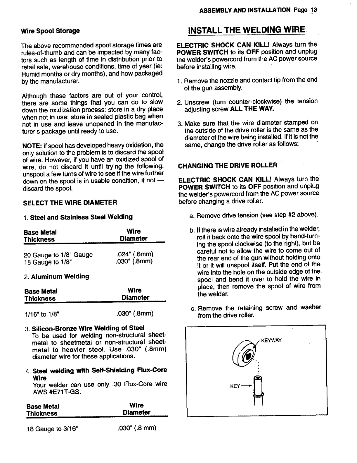
c, Remove the retaining screw and washer
from the drive roller.
KE'f_NAY
KEY _
18 Gauge to 3/t6" .030" (.8 mm)
ASSEMBLY AND INSTALLATION Page 14
d. Remove the drive roller by pulling it straight
out and off the drive motor shaft.
e. Find the side of the drive roller that is
stamped with the same wire diameter as
that of the wire being installed. Push the
drive roller onto the drive motor shaft. Make
sure the side stamped with the desired wire
diameter is facing out. IMPORTANT! Make
sure the key remains properly installed in its
slot in the drive motor shaft.
f. Replace the drive roller retaining screw and
washer, then tighten securely.
4. Remove the wire spool holder from the deck of
the welder by pulling up lightly on the spindle
while pulling firmly outward on the tab of the wire
spool holder until it clears the hold-down tabs on
the deck of the welder.
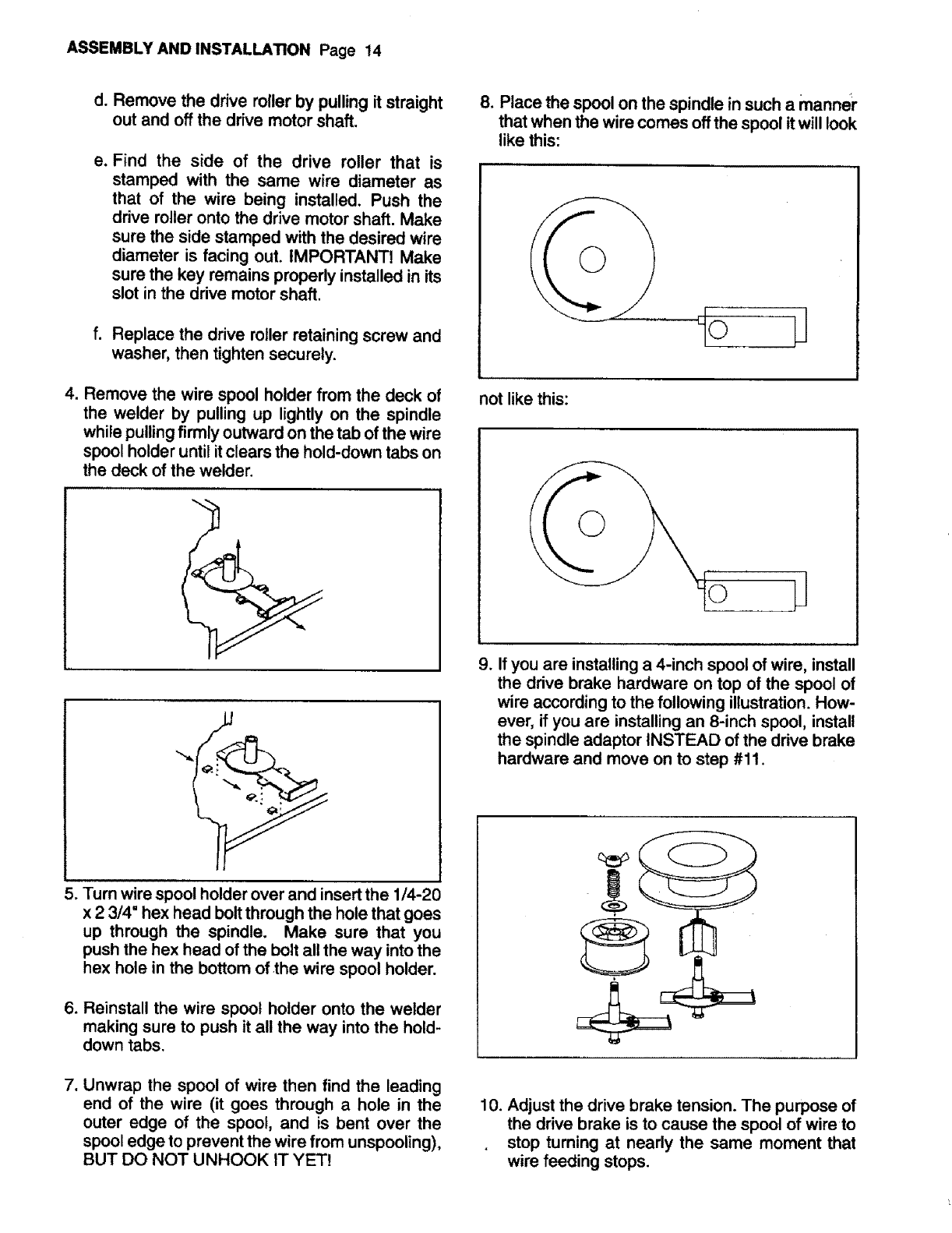
8. Place the spool on the spindle in such a manner
that when the wire comes off the spool it will look
like this:
not like this:
o
5. Turn wire spool holder over and insert the 1/4-21
x 2 3/4" hex head bolt through the hole that goes
up through the spindle. Make sure that you
push the hex head of the bolt all the way into the
hex hole in the bottom of the wire spool holder.
6. Reinstall the wire spool holder onto the welder
making sure to push it all the way into the hold-
down tabs.
7. Unwrap the spool of wire then find the leading
end of the wire (it goes through a hole in the
outer edge of the spool, and is bent over the
spool edge to prevent the wire from unspooling),
BUT DO NOT UNHOOK IT YET!
9. If you are installing a 4-inch spool of wire, install
the drive brake hardware on top of the spool of
wire according to the following illustration. How-
ever, if you are installing an 8-inch spool, install
the spindle adaptor INSTEAD of the drive brake
hardware and move on to step #11.
10. Adjust the drive brake tension. The purpose of
the drive brake is to cause the spool of wire to
stop turning at nearly the same moment that
wire feeding stops.
a. With one hand, turn the wire spool and con-
tinue turning it while adjusting the tension.
b. With your free hand, tighten (turn clockwise)
the wing-nut.
c. Stop tightening when drag is felt on the wire
spool that you are tuming, then stop hand
turning the wire spool.
NOTE: If TOO MUCH tension is applied, the wire
will slip on the drive roller or will not be able to be
fed at all. If TOO LITTLE tension is applied, the
spool of wire will want to unspool itself. Readjust
the drive brake tenion as necessary to correct for
either of these problems.
11. After checking to make sure that your welder is
disconnected from the AC power source, free
the leading-end of the wire from the spool, but
do not let go of it until told to do so, or the wire
will unspool itself.
t2. Using awire cutter, cut the bent end off the
leading-end of the wire so that only astraight
leading-end remains.
13. Hold the tension arm up off the drive roller and
insert the leading-end of the wire into the inlet
guide tube. Then push it across the drive roller
and into the gun assembly about six inches.
14. Line the wire up in the outside groove of the
drive roller, then allow the drive tension arm to
drop onto the drive roller.
15. Tighten (turn clockwise) the tension adjusting
screw until the tension roller is applying enough
force on the wire to prevent it from slipping out
of the drive assembly. NOW YOU CAN LET
GO OF THE WIRE.
16. Plug the welder's powercord into the AC power
source, turn the POWER SWITCH on the front
of the welder to either HIGH or LOW, and set
the WIRE SPEED control to the middle of the
wire speed range.
17. Pull the trigger on the welding gun to feed the
wire through the gun assembly.
ARC FLASH CAN INJURE EYES! To reduce the
risk of arc flash, make certain that the welding wire,
when it finally comes out of the endof the gun, does
not touch the ground calmp or any grounded piece
of metal. IMPORATANT! The welding wire is car-
ASSEMBLY AND INSTALLATION Page,_15_
rying welding current whenever the welder, is,
turned on -- WHETHER THE TRIGGER i_
PULLED OR NOT!
18. When at least and inch of wire sticks out past
the end of the gun, release the trigger.
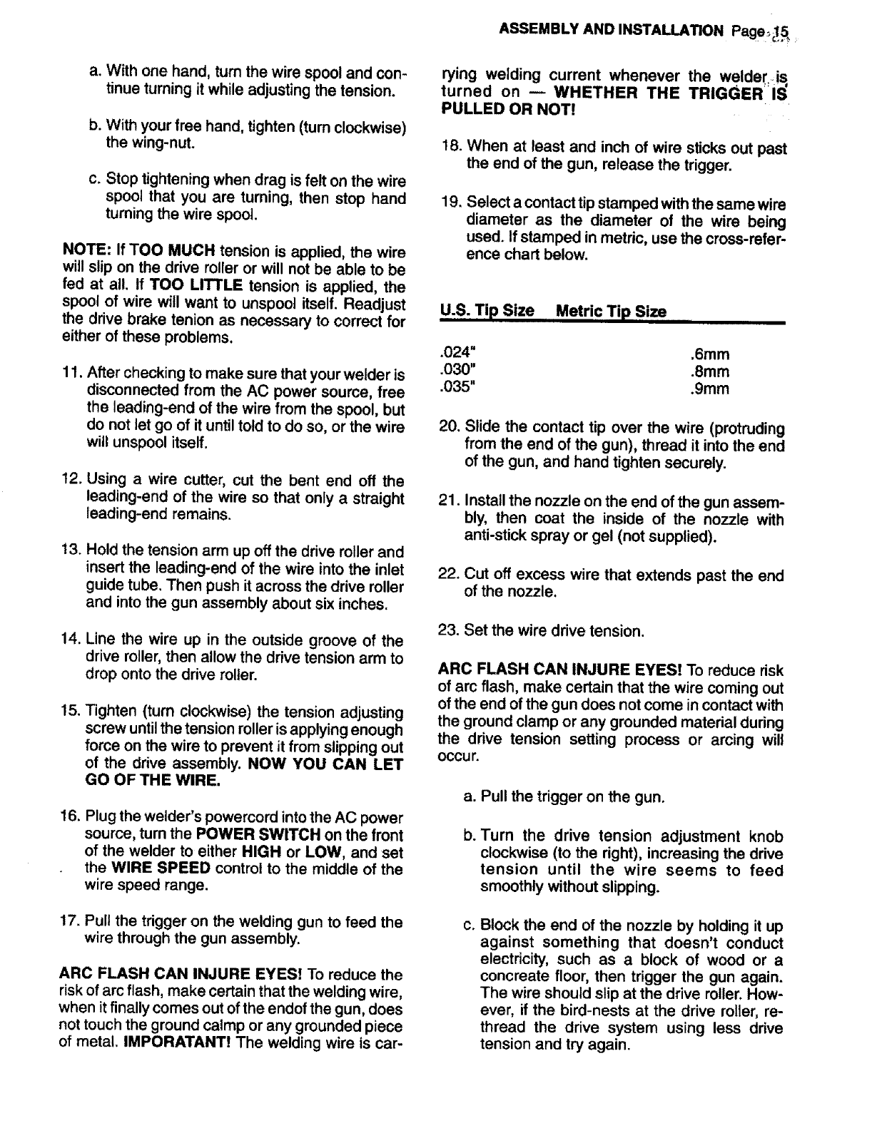
19. Select a contact tip stamped withthe same wire
diameter as the diameter of the wire being
used. If stamped in metric, use the cross-refer-
ence chart below.
U.S:Tip Size Metric Tip Size .....
.024"
.030"
.035"
.6mm
.8mm
.gmm
20.
21.
22.
Slide the contact tip over the wire (protruding
from the end of the gun), thread it into the end
of the gun, and hand tighten securely.
Install the nozzle on the end of the gun assem-
bly, then coat the inside of the nozzle with
anti-stick spray or gel (not supplied).
Cut off excess wire that extends past the end
of the nozzle.
23. Set the wire drive tension.
ARC FLASH CAN INJURE EYES! To reduce risk
of arc flash, make certain that the wire coming out
of the end ofthe gun does not come in contact with
the ground clamp or any grounded material during
the drive tension setting process or arcing will
occu r.
a. Pull the trigger on the gun.
b. Turn the drive tension adjustment knob
clockwise (to the right), increasing the drive
tension until the wire seems to feed
smoothly without slipping.
c. Block the end of the nozzle by holding it up
against something that doesn't conduct
electricity, such as a block of wood or a
concreate floor, then trigger the gun again.
The wire should slip at the drive roller. How-
ever, if the bird-nests at the drive roller, re-
thread the drive system using less drive
tension and try again.
ASSEMBLY AND INSTALLATION Page 16
When set correctly, there should be no slippage
between the wire and the drive teller under normal
conditions, but if an obstruction occurs along the
wire feed path, the wire should then slip on the
drive roller.
INSTALLING ALUMINUM WIRE
Install aluminum wire the same as steel wire, but
with the following exceptions.
a. Select only .030" diameter wire of the 5356
aluminum alloy. Use a .035" contact tip, the
composite rubber drive roller (Part # 4324),
and teflon line (Part # 4325).
b. Be sure to adjust the drive tension properly.
Aluminum wire is very sensitive to slight
changes in drive tension.
LL
PREPARING TO WELD Page .17
PREPARING TO WELD
PREPARING A SAFE WELDING
WORK AREA bystanders in the welding area. It is amust that the
welding work area be cleared of all flammables
and that a type ABC chemical fire extinguisher is
always close at hand.
ELECTRIC SHOCK CAN KILL!
_]_JD] ARC RAYS CAN INJURE EYES AND
BURN SKIN!
READ The SAFETY INSTRUCTIONS! They wilt
tell you how to properly prepare for welding by:
1. Preparing a safe welding work area.
2. Providing the necessary personal eye and skin
protection for you and all bystanders in the weld-
ing area.
FIRE OR EXPLOSION CAN CAUSE
DEATH, INJURY, AND PROPERTY DAMAGEI
3. Providing adequate ventilation, or respiration
equipment if necessary, to protect you and any
bystanders in the welding area.
FUMES, GASSES, AND VAPORS CAN
CAUSE DISCOMFORT, ILLNESS, AND DEATH!
IMPROPER HANDLING AND MAIN-
TENANCE OF COMPRESSED GAS CYLIN-
DERS AND REGULATORS CAN RESULT IN
SERIOUS INJURY OR DEATHI
DO NOT PROCEED TO PREPARE TO WELD
until you read and understand each of the five
parts of the SAFETY INSTRUCTIONS section in
this manual. The SAFETY INSTRUCTIONS will
tell you how to REDUCE THE RISKS OF DEATH,
INJURY, ILLNESS, DISCOMFORT, AND PROP-
ERTY DAMAGE to you, the bystanders in the
welding area, and property in the vicinity of the
welding area from SHOCK HAZARDS, FLASH
HAZARDS, FIRE HAZARDS, FUME HAZARDS,
AND COMPRESSED GASSES AND EQUIP-
MENT HAZARDS.
An important factor in making a satisfactory weld is
preparation. This includes the study of the welding
process and equipment by the operator and then
practicing on scrap material before actual welding
jobs are attempted. An organized, well-lighted
work area should be available to provide comfort,
convenience, and safety to the operator and all
PREPARING THE WORK PIECE
Much of the success in producing a quality weld
can be attributed to the preparation of the weld-
joint area of the work piece.
1. Clean the weld-joint area of dirt, rust, scale, oil,
and/or paint. Failure to do so may result in a
porous, brittle weld.
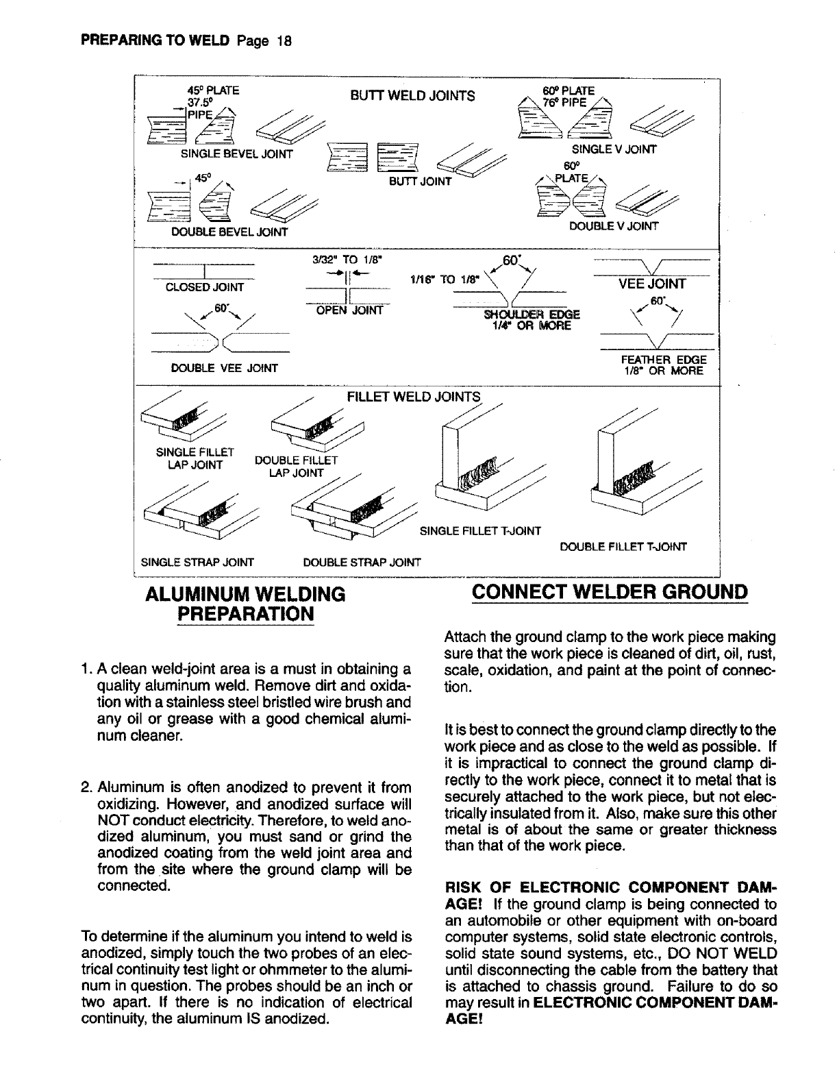
,Select atype of joint appropriate for your appli-
cation. The more popular types ofwelding joints
are illustrated inthe TYPES OF JOINTS chart at
the end of this section.
NOTE: If you select a BUTT WELD JOINT, you
may have to prepare the edges of the metal to be
joined by grinding a bevel on the edges.
GRINDING METAL CAN INJURE EYES! To re-
duce the risk of eye injury, ALWAYS wear goggles
and inspect the grinder to verify that it is in good
condition before using.
During the welding process, the work pieces will
become hot and tend to expand causing the pieces
to shift from their initial position. If possible, it is
best if the work pieces can be securely clamped
(before welding) into the position desired after
welding is completed.
PREPARING TO WELD Page 18
450 PLATE
37.5 °
SINGLE BEVELJOINT
DOUBLE BEVEL JOINT
BUTT WELD JOINTS
BUTT JOINT
600PLATE
SINGLEV JOINT
6O0
DOUBLEVJOINT
I
CLOSED JOINT
DOUBLE VEE JOINT
3/32" TO 1/8" 60--
"-_N '_''r 1/16" TO 1/8" _
OPEN JOINT SHOUI.._ER EDGE
1/4" OR MORE
V
VEE JOINT
--\/
FEATHER EDGE
1/8" OR MORE
SINGLE FILLET
LAP JOINT
LET WELD JOINTS
DOUBLE FILLET __
SINGLE FILLET T-JOINT
SINGLE STRAP JOINT DOUBLE STRAP JOINT
DOUBLE FILLET T-JOINT
ALUMINUM WELDING
PREPARATION
1. A clean weld-joint area is a must in obtaining a
quality aluminum weld. Remove dirt and oxida-
tion with a stainless steel bristled wire brush and
any oil or grease with a good chemical alumi-
num cleaner.
2. Aluminum is often anodized to prevent it from
oxidizing. However, and anodized surface will
NOT conduct electricity. Therefore, to weld ano-
dized aluminum, you must sand or grind the
anodized coating from the weld joint area and
from the site where the ground clamp will be
connected.
To determine if the aluminum you intend to weld is
anodized, simply touch the two probes of an elec-
trical continuity test light or ohmmeter to the alumi-
num in question. The probes should be an inch or
two apart. If there is no indication of electrical
continuity, the aluminum IS anodized.
CONNECT WELDER GROUND
Attach the ground clamp to the work piece making
sure that the work piece is cleaned of dirt, oil, rust,
scale, oxidation, and paint at the point of connec-
tion.
It is best to connect the ground clamp directly to the
work piece and as close to the weld as possible. If
it is impractical to connect the ground clamp di-
rectly to the work piece, connect it to metal that is
securely attached to the work piece, but not elec-
tricallyinsulated from it. Also, make sure thisother
metal is of about the same or greater thickness
than that of the work piece.
RISK OF ELECTRONIC COMPONENT DAM-
AGE! If the ground clamp is being connected to
an automobile or other equipment with on-board
computer systems, solid state electronic controls,
solid state sound systems, etc., DO NOT WELD
until disconnecting the cable from the battery that
is attached to chassis ground. Failure to do so
may result in ELECTRONIC COMPONENT DAM-
AGE!

OPERATION Page 19
OPERATION
GETTING TO KNOW YOUR NEW
WELDER
Whether you have welded before or not, it is impor-
tant that you become familiar with your new
welder, its controls, and the results achieved at
different settings. We strongly recommend that
you practice with your new welder on scrap metal
trying different heat settings, base metal thick-
nesses, and welding positions for each type and
size of wire that you will be using. By doing this
you will gain a feel for how changes in these
welding variables affect the weld.
Of course, if you have not MIG welded before, you
will need to develop welding skills and techniques
as well. The self-taught welder learns through a
process of trial and error. The best way to teach
yourself how to weld is with short periods of prac-
tice at regular intervals.
DO NOT ATTEMPT TO WELD on any valuable
equipment until you have made practice welds on
scrap metal that can be discarded. The scrap
metal should be of the same type and thickness as
that of the item to be welded. Only after you are
satisfied that your practice welds are of good
strength and appearance, should you attempt your
actual welding job.
SETTING THE CONTROLS
1. The POWER SWITCH has three settings: LOW,
OFF, and HIGH. When in the OFF position,
power is disconnected from all welder functions.
The LOW position is selected for welding steel
thicknesses of 16 gauge or thinner. The HIGH
position is selected for steel thicker than 16
gauge. The variables that affect the heat selec-
tor setting are wire type and size, base metal
type and thickness, and desired penetration.
2. The WIRE SPEED CONTROL is variable from
SLOW to FAST. To achieve successful welding
results, it is important that the wire be fed at the
same rate it is being melted off into the weld
puddle; if too fast the wire will tend to push the
gun away from the work piece and if too slow,
the wire will bum back into, and may damage
the contact tip. In either case, an extremely
poor weld will result.
"TUNING IN" THE WIRE SPEED is one of the
most important parts of MIG welder operation and
must be done before starting each welding job or
whenever any of the following variables are
changed: heat setting, wire diameter, or wire type.
a. Set up and ground ascrap piece of the same
type of metal that you will be welding, it
should be equal to or greater than the thick-
ness of the actual work piece and free of
paint, oil, rust, etc.
b. Select a heat setting.
c. Hold the gun in one hand atlowing the nozzle
to rest on the edge of the work piece farthest
away from you and at an angle similar to that
which will be used when actually welding.
d. With your free hand, turn the WIRE SPEED
control to maximum and continue to hold
onto the knob.
ARC RAYS CAN INJURE EYES AND BURN
SKINI To reduce risk of injury from arc rays, never
strike awelding arc until you and all bystanders in
the welding area have welding helmets or shields
in place and are wearing the recommended pro-
tective clothing. DO NOT CONTINUE unless you
have read, understand, and intend to follow the
entire SAFETY INSTRUCTIONS section of this
manual.
e, Lower your welding helmet and pull the trig-
ger on the gun to start an arc, then begin to
drag the gun toward you while turning down
on the WIRE SPEED control knob at the
same time.
LISTEN! As you decrease the wire speed,
the sound that the arc makes will change
from a sputtering to a smooth, high-pitched
buzzing sound and then will begin sputtering
again if you decrease the wire speed too far.
Selecting the best wire speed setting is much the
same as "tuning in" a radio: continue decreasing
the wire speed until the arc noise passes the best-
sounding, high-pitched buzz and begins to sputter
again, then turn the WIRE SPEED control the
opposite direction until you come back to the best
sounding arc noise. The welder is now "tuned in"
and welding can begin.
OPERATION Page 20
REPEAT THIS TUNE-IN PROCEDURE if you se-
lect a new heat setting, a different diameter _vire,
or a different type wire.
NOTE: When "tuning-in" the wire speed for self-
shielding flux-core wire, you will find a very wide
"best-sounding range", spanning as much as 60
degrees on the WIRE SPEED contro!. It is impor-
tant to know that the heat of the arc and penetra-
tion into the base metal increases as the wire
speed is increased within the "best-sounding
range" for a given heat setting.
Therefore, you can use the wire speed control to
slightlyincrease or decrease heat and penetration
for a given heat settingby selecting higheror lower
wire speed settings WITHIN the _est-sounding
range".
HOLDING THE GUN
The best way to hold the welding gun is the way
that feels most comfortable to you. While practic-
ing touse your new welder, experiment holding the
gun in different positions untilyou find the one that
seems to work best for you.
Position of the Gun to the Work Piece
There are two angles of the gun nozzle in relation
to the work piece that must be considered when
welding.
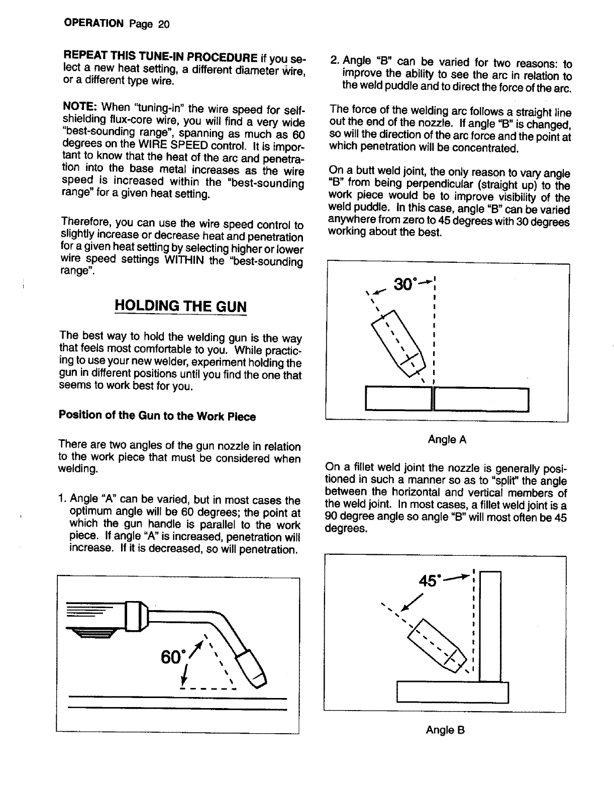
1. Angle "A" can be varied, but in most cases the
optimum angle will be 60 degrees; the point at
which the gun handle is parallel to the work
piece. If angle "A" is increased, penetration will
increase. If it is decreased, so will penetration.
i J,
8oii
==lllliHi .................. ==lHi
,lllllll
2. Angle "B" can be varied for two reasons: to
improve the ability to see the arc in relation to
the weld puddle and to directthe force of the arc.
The force of the welding arc follows a straight tine
out the end of the no>>te. If angle "B" is changed,
so will the direction of the arc force and the point at
which penetration will be concentrated.
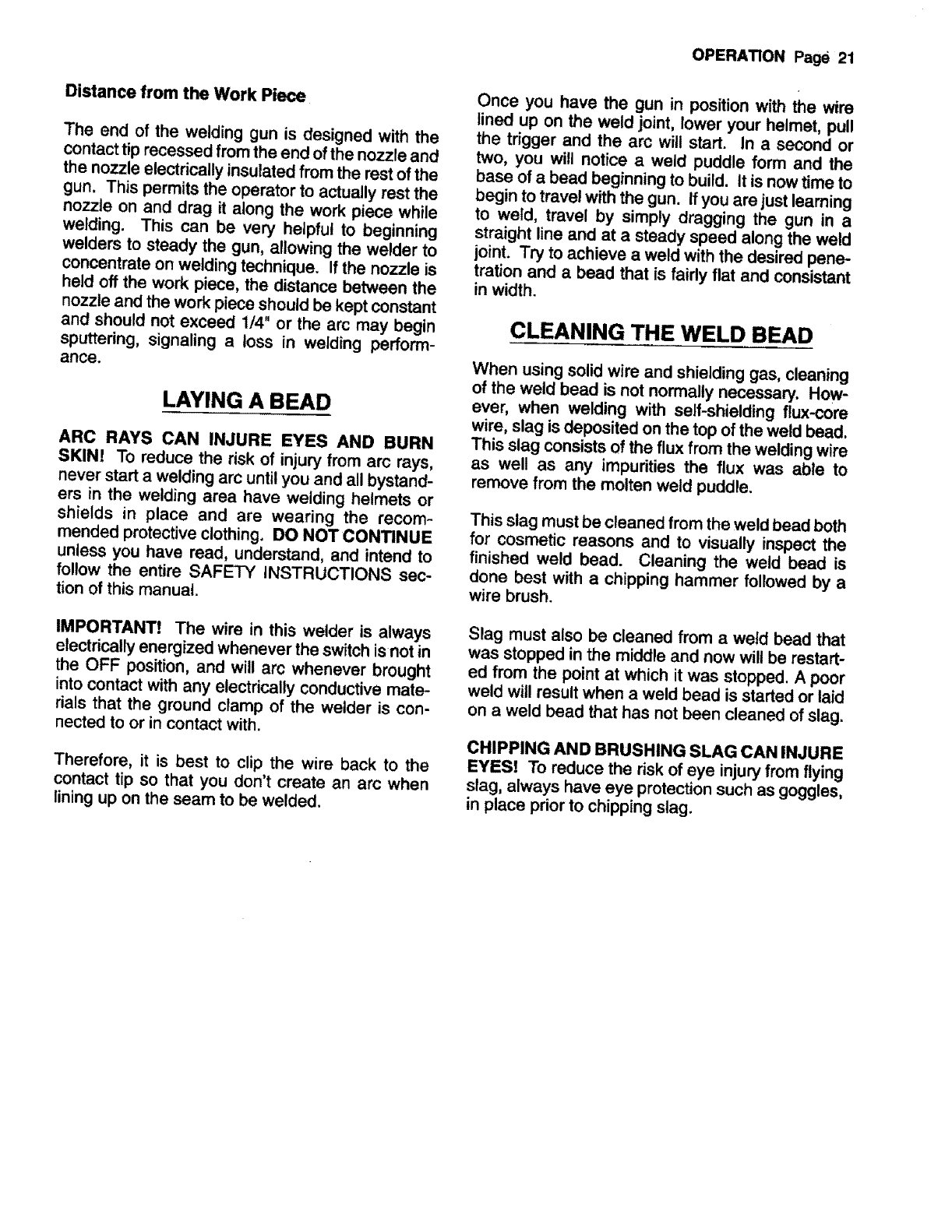
On a butt weld joint, the only reason to vary angle
"B" from being perpendicular (straight up) to the
work piece would be to improve visibility of the
weld puddle. In this case, angle "13'can be varied
anywhere from zero to 45 degrees with30 degrees
working about the best.
30 °,,,,_P II
,_ _v,'*" !
\I
!
I
!
t
!
!
•!
Angle A
On a fillet weld joint the nozzle is generally posi-
tioned in such a manner so as to "split" the angle
between the horizontal and vertical members of
the weld joint. In most cases, a fillet weld joint is a
90 degree angle so angle "13"will most often be 45
degrees.
45"..---_
.f/
%%%
1lI
Angle B
Distance from the Work Piece
The end of the welding gun is designed with the
contact tip recessed from the end of the nozzle and
the nozzle electrically insulated from the rest of the
gun. This permits the operator to actually rest the
nozzle on and drag it along the work piece while
welding. This can be very helpful to beginning
welders to steady the gun, allowing the welder to
concentrate on welding technique. If the nozzle is
held off the work piece, the distance between the
nozzle and the work piece should be kept constant
and should not exceed 1/4" or the arc may begin
sputtering, signaling a toss in welding perform-
ance.
LAYING A BEAD
ARC RAYS CAN INJURE EYES AND BURN
SKIN! To reduce the risk of injury from arc rays,
never start awelding arc until you and all bystand-
ers in the welding area have welding helmets or
shields in place and are wearing the recom-
mended protective clothing. DO NOT CONTINUE
unless you have read, understand, and intend to
follow the entire SAFETY iNSTRUCTIONS sec-
tion of this manual.
IMPORTANT! The wire in this welder is always
electrically energized whenever the switch is not in
the OFF position, and will arc whenever brought
into contact with any electrically conductive mate-
rials that the ground clamp of the welder is con-
nected to or in contact with.
Therefore, it is best to clip the wire back to the
contact tip so that you don't create an arc when
lining up on the seam to be welded.
OPERATION Page 21
Once you have the gun in position with the wire
lined up on the weld joint, lower your helmet, pull
the trigger and the arc will start. In a second or
two, you will notice aweld puddle form and the
base ofa bead beginning to build. It is now time to
begin to travel with the gun. If you are just learning
to weld, travel by simply dragging the gun in a
straight line and at a steady speed along the weld
joint. Try to achieve a weld with the desired pene-
tration and abead that is faidy fiat and consistant
inwidth.
CLEANING THE WELD BEAD
When using solid wire and shielding gas, cleaning
of the weld bead is not normally necessary. How-
ever, when welding with self-shielding flux-core
wire, slag is deposited on the top of the weld bead.
This slag consists of the flux from the welding wire
as well as any impurities the flux was able to
remove from the molten weld puddle.
This slag must be cleaned from the weld bead both
for cosmetic reasons and to visually inspect the
finished weld bead. Cleaning the weld bead is
done best with a chipping hammer followed by a
wire brush.
Slag must also be cleaned from a weld bead that
was stopped in the middle and now will be restart-
ed from the point at which it was stopped. A poor
weld will result when a weld bead is started or laid
on a weld bead that has not been cleaned of slag.
CHIPPING AND BRUSHING SLAG CAN INJURE
EYES! To reduce the risk of eye injury from flying
slag, always have eye protection such as goggles,
in place prior to chipping slag.
WELDING TECHNIQUES Page 22
WELDING TECHNIQUES
As you become more familiar with your new welder
and better at laying some simple weld beads, you
can begin to try some different welding techniques
to improve and add versatility to your welding
skills.
TRAVELING WITH THE GUN
Gun travel refers to the movement of the gun along
the weld joint and is broken into two elements:
Direction and Speed. A solid weld bead requires
that the welding gun be moved steadily and at the
right speed along the weld joint. Moving the gun
too fast, too slow, or irratically will prevent proper
fusion or create a lumpy, uneven bead.
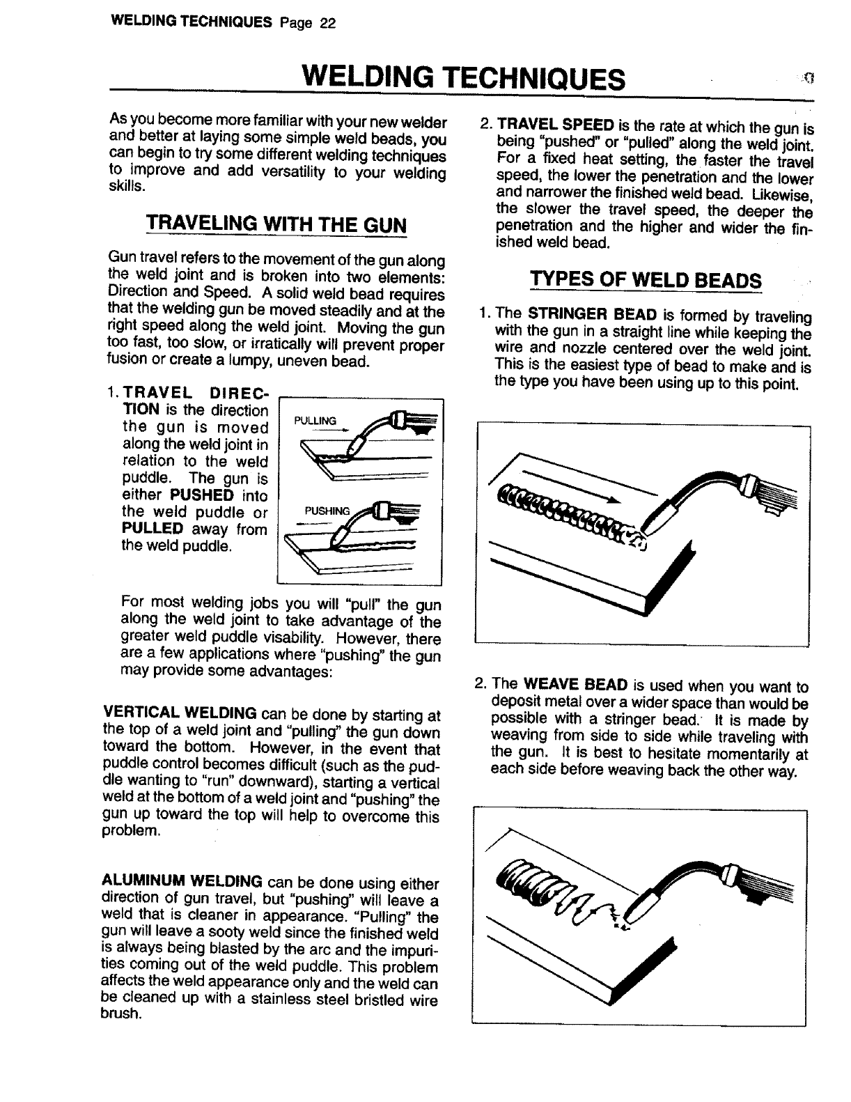
1. TRAVEL DIREC-
TION is the direction
the gun is moved
along the weld joint in
relation to the weld
puddle. The gun is
either PUSHED into
the weld puddle or
PULLED away from
the weld puddle.
PULLING
PUSHING
For most welding jobs you will "pull" the gun
along the weld joint to take advantage of the
greater weld puddle visability. However, there
are a few applications where "pushing" the gun
may provide some advantages:
VERTICAL WELDING can be done by starting at
the top of aweld joint and "pulling" the gun down
toward the bottom. However, in the event that
puddle control becomes difficult (such as the pud-
dle wanting to "run" downward), starting avertical
weld at the bottom of a weld joint and "pushing" the
gun up toward the top will help to overcome this
problem.
ALUMINUM WELDING can be done using either
direction of gun travel, but "pushing" will leave a
weld that is cleaner in appearance. "Pulling" the
gun will leave a sooty weld since the finished weld
is always being blasted by the arc and the impuri-
ties coming out of the weld puddle. This problem
affects the weld appearance only and the weld can
be cleaned up with a stainless steel bristled wire
brush.
.TRAVEL SPEED is the rate at which the gun is
being "pushed" or "pulled" along the weld joint.
For a fixed heat setting, the faster the travel
speed, the lower the penetration and the lower
and narrower the finished weld bead. Likewise,
the slower the travel speed, the deeper the
penetration and the higher and wider the fin-
ished weld bead.
TYPES OF WELD BEADS -
1. The STRINGER BEAD is formed by traveling
with the gun in astraight line while keeping the
wire and nozzle centered over the weld joint.
This is the easiest type of bead to make and is
the type you have been using up to this point.
2. The WEAVE BEAD is used when you want to
deposit metal over a wider space than would be
possible with a stringer bead.' It is made by
weaving from side to side while traveling with
the gun. It is best to hesitate momentarily at
each side before weaving back the other way.
WELDING TECHNIQUES Page 23
WELDING POSITIONS
There are four basic welding positions: fiat, hori-
zontal, vertical, and overhead.
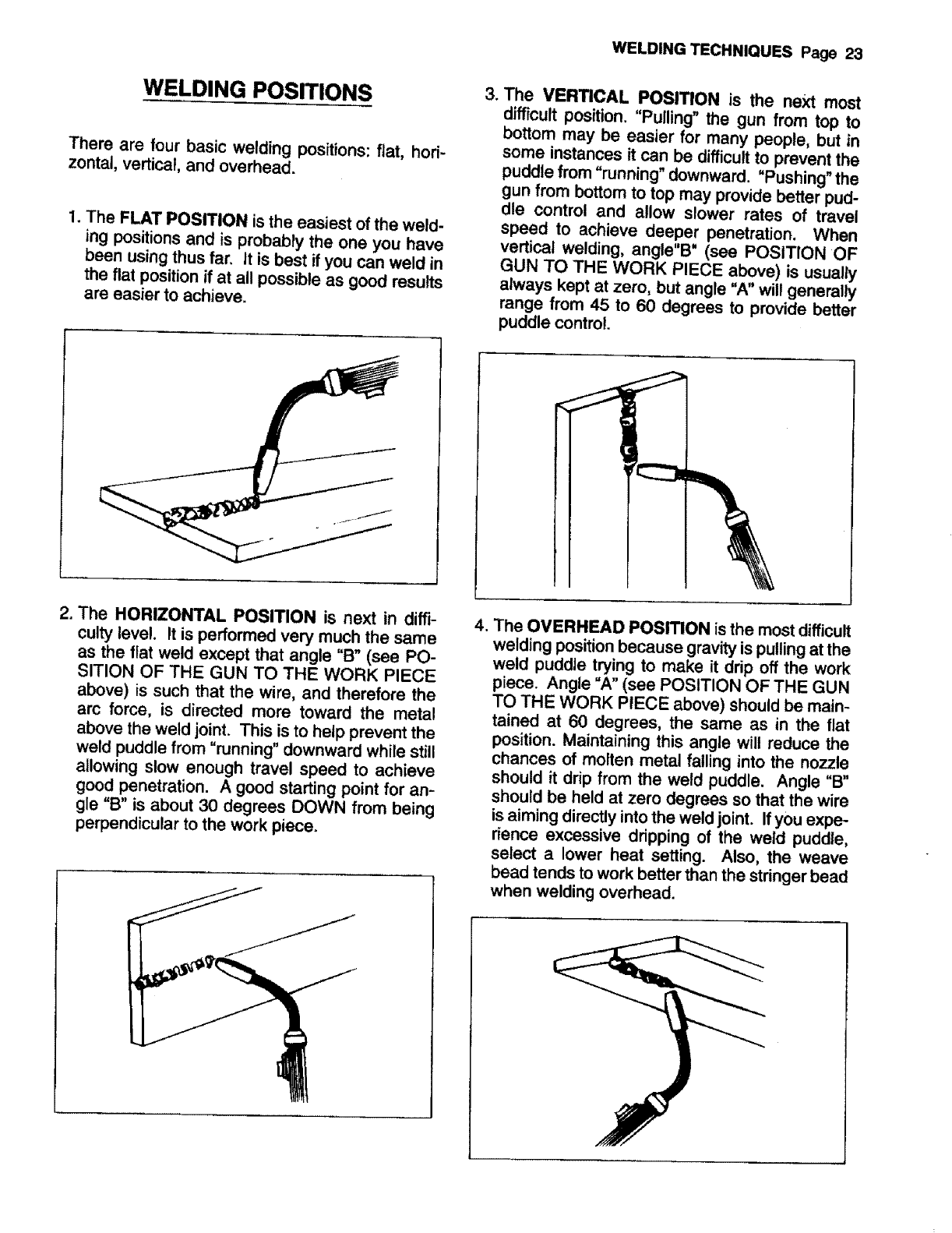
1. The FLAT POSITION is the easiest of the weld-
ing positions and is probably the one you have
been using thus far. It is best if you can weld in
the fiat position if at all possible as good results
are easier to achieve.
=The VERTICAL POSITION is the next most
difficult position. "Pulling" the gun from top to
bottom may be easier for many people, but in
some instances it can be difficult to prevent the
puddle from "running" downward. "Pushing" the
gun from bottom to top may provide better pud-
dle control and allow slower rates of travel
speed to achieve deeper penetration. When
vertical welding, angle"B" (see POSITION OF
GUN TO THE WORK PIECE above) is usually
always kept at zero, but angle "A" wil! generally
range from 45 to 60 degrees to provide better
puddle control.
2. The HORIZONTAL PosmoN is next in diffi-
culty level. It is performed very much the same
as the flat weld except that angle "B" (see PO-
SITION OF THE GUN TO THE WORK PIECE
above) is such that the wire, and therefore the
arc force, is directed more toward the metal
above the weld joint. This is to help prevent the
weld puddle from "running" downward while still
allowing slow enough travel speed to achieve
good penetration. A good starting point for an-
gle "B" is about 30 degrees DOWN from being
perpendicular to the work piece.
,The OVERHEAD POSITION is the most difficult
welding position because gravity is pulling at the
weld puddle trying to make it drip off the work
piece. Angle =A" (see POSITION OF THE GUN
TO THE WORK PIECE above) should be main-
tained at 60 degrees, the same as in the flat
position. Maintaining this angle will reduce the
chances of molten metal falling into the nozzle
should it drip from the weld puddle. Angle "B"
should be held at zero degrees so that the wire
is aiming directly into the weld joint. If you expe-
rience excessive dripping of the weld puddle,
select a lower heat setting. Also, the weave
bead tends to work better than the stringer bead
when welding overhead.
WELDING TECHNIQUES Page 24
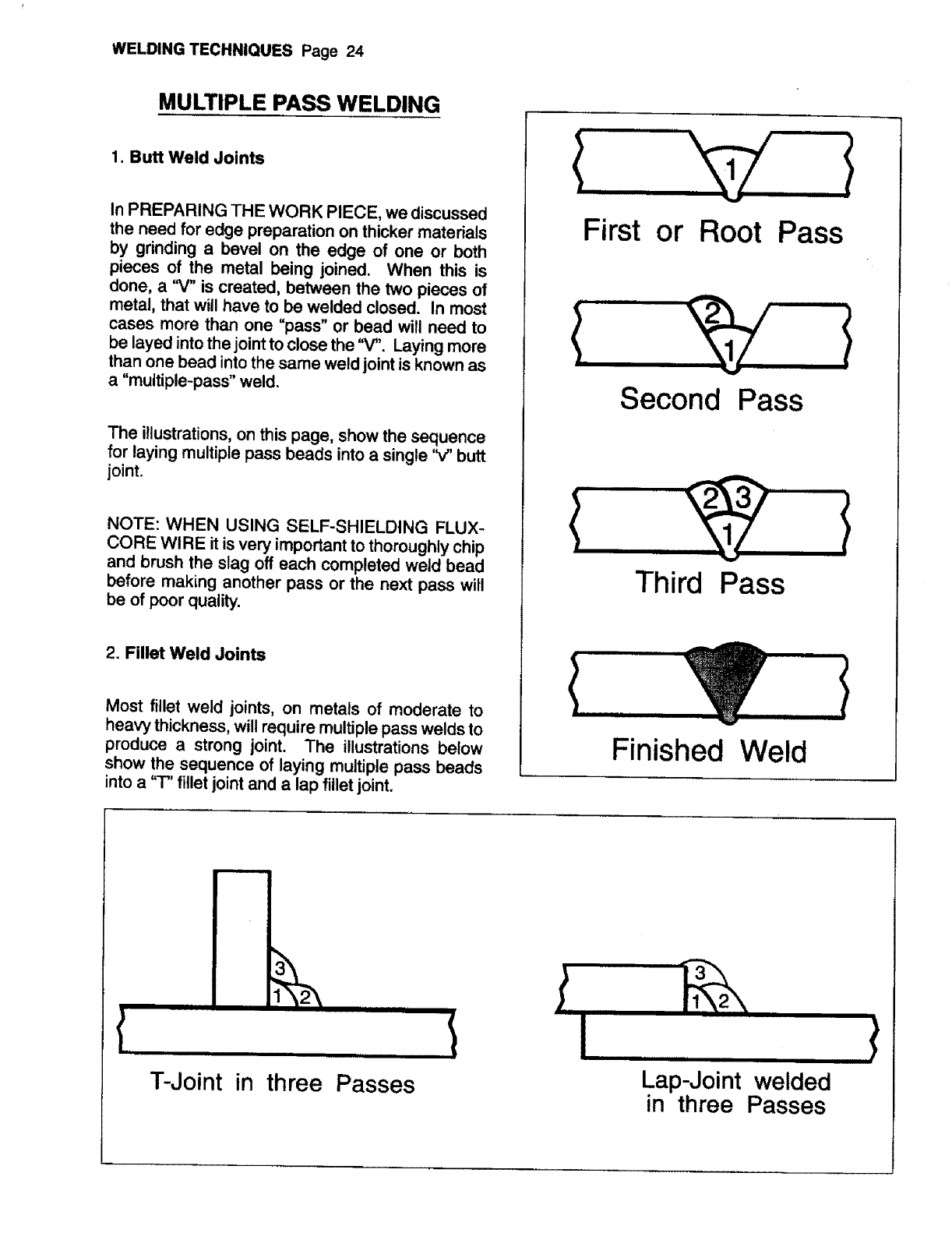
MULTIPLE PASS WELDING
1. Butt Weld Joints
In PREPARING THE WORK PIECE, we discussed
the need for edge preparation on thicker materials
by grinding a bevel on the edge of one or both
pieces of the metal being joined. When this is
done, a '_/" is created, between the two pieces of
metal, that will have to be welded closed. In most
cases more than one "pass" or bead will need to
be layed into the joint to close the "V". Laying more
than one bead into the same weld joint is known as
a "multiple-pass" weld.
The illustrations, on this page, show the sequence
for laying multiple pass beads into a single 'V' butt
joint.
NOTE: WHEN USING SELF-SHIELDING FLUX-
CORE WIRE it is very important to thoroughly chip
and brush the slag off each completed weld bead
before making another pass or the next pass will
be of poor quality.
2. Fillet Weld Joints
Most fillet weld joints, on metals of moderate to
heavy thickness, will require multiple pass welds to
produce a strong joint. The illustrations below
show the sequence of laying multiple pass beads
into a "T" fillet joint and a lap fillet joint.
,,,,,,,,,,,,,,,,,
First or Root Pass
Second Pass
Third Pass
Finished Weld
III
ill iii ii iiii I
T-Joint in three Passes
I I i1_
Iiiiiii
Lap-Joint welded
in three Passes
iiii ii i
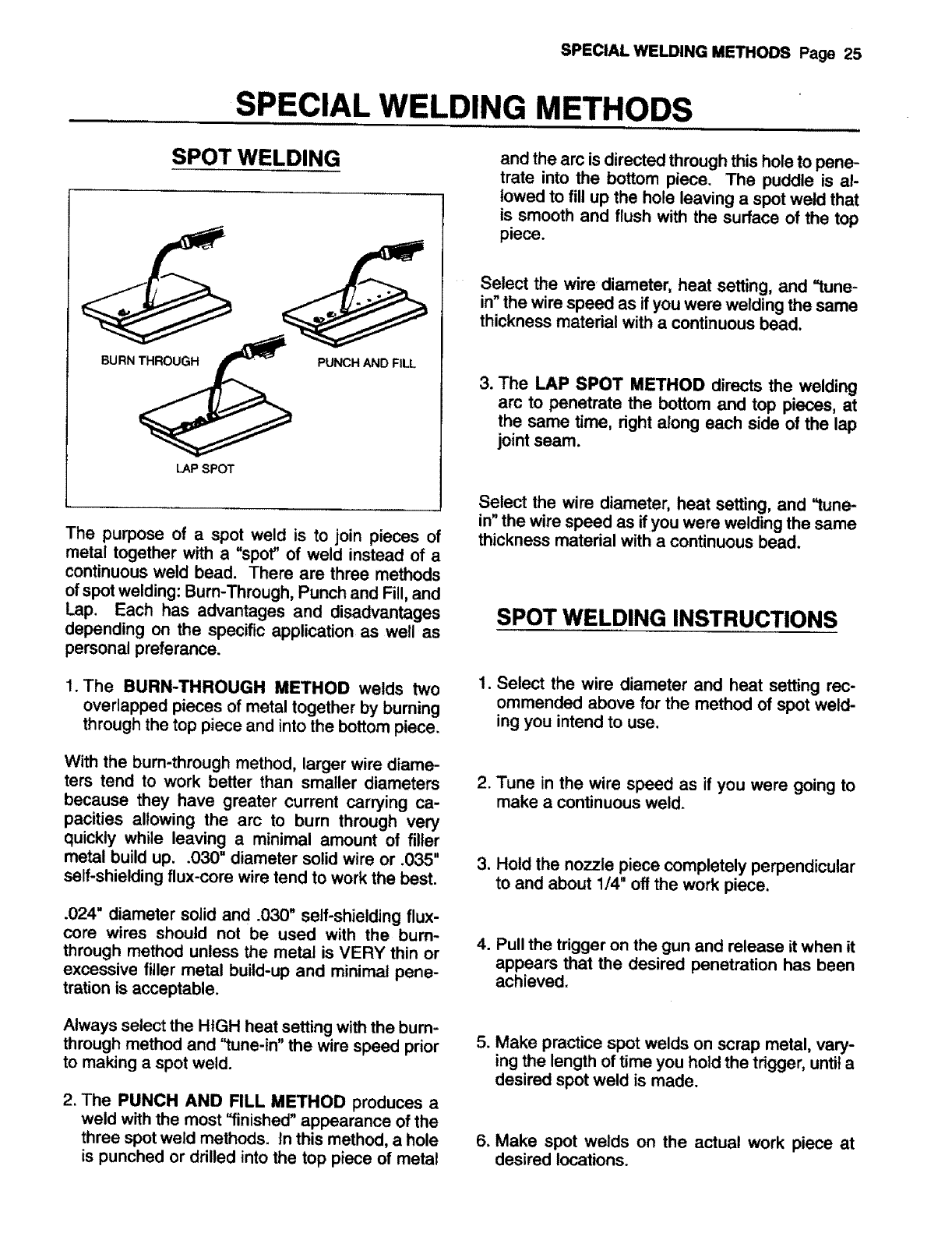
SPECIAL WELDING METHODS Page 25
SPECIAL WELDING METHODS
SPOT WELDING
BURN THROUGH PUNCH AND FILL
LAP SPOT
The purpose of aspot weld is to join pieces of
metal together with a "spot" of weld instead of a
continuous weld bead. There are three methods
of spot welding: Bum-Through, Punch and Fill, and
Lap. Each has advantages and disadvantages
depending on the specific application as well as
personal preferance.
1. The BURN-THROUGH METHOD welds two
overlapped pieces of metal together by burning
through the top piece and into the bottom piece.
With the burn-through method, larger wire diame-
ters tend to work better than smaller diameters
because they have greater current carrying ca-
pacities allowing the arc to burn through very
quickly while leaving a minimal amount of filler
metal build up..030" diameter solid wire or .035"
self-shielding flux-core wire tend to work the best.
.024" diameter solid and .030" self-shielding flux-
core wires should not be used with the bum-
through method unless the metal is VERY thin or
excessive filler metal build-up and minimal pene-
tration is acceptable.
Always select the HIGH heat setting with the burn-
through method and "tune-in" the wire speed prior
to making a spot weld.
2. The PUNCH AND FILL METHOD produces a
weld with the most "finished" appearance of the
three spot weld methods, tn this method, a hole
is punched or drilled into the top piece of metal
and the arc is directed through this hole to pene-
trate into the bottom piece. The puddle is al-
lowed to fill up the hole leaving a spot weld that
is smooth and flush with the surface of the top
piece.
Select the wire diameter, heat setting, and =tune-
in" the wire speed as if you were welding the same
thickness material with acontinuous bead.
3. The LAP SPOT METHOD directs the welding
arc to penetrate the bottom and top pieces, at
the same time, right along each side of the lap
joint seam.
Select the wire diameter, heat setting, and =tune-
in"the wire speed as if you were welding the same
thickness material with a continuous bead.
SPOT WELDING INSTRUCTIONS
1. Select the wire diameter and heat setting rec-
ommended above for the method of spot weld-
ing you intend to use.
2. Tune in the wire speed as if you were going to
make a continuous weld.
3. Hold the nozzle piece completely perpendicular
to and about 1/4" off the work piece,
4. Pull the trigger on the gun and release it when it
appears that the desired penetration has been
achieved.
5. Make practice spot welds on scrap metal, vary-
ing the length of time you hold the trigger, until a
desired spot weld is made.
6. Make spot welds on the actual work piece at
desired locations.
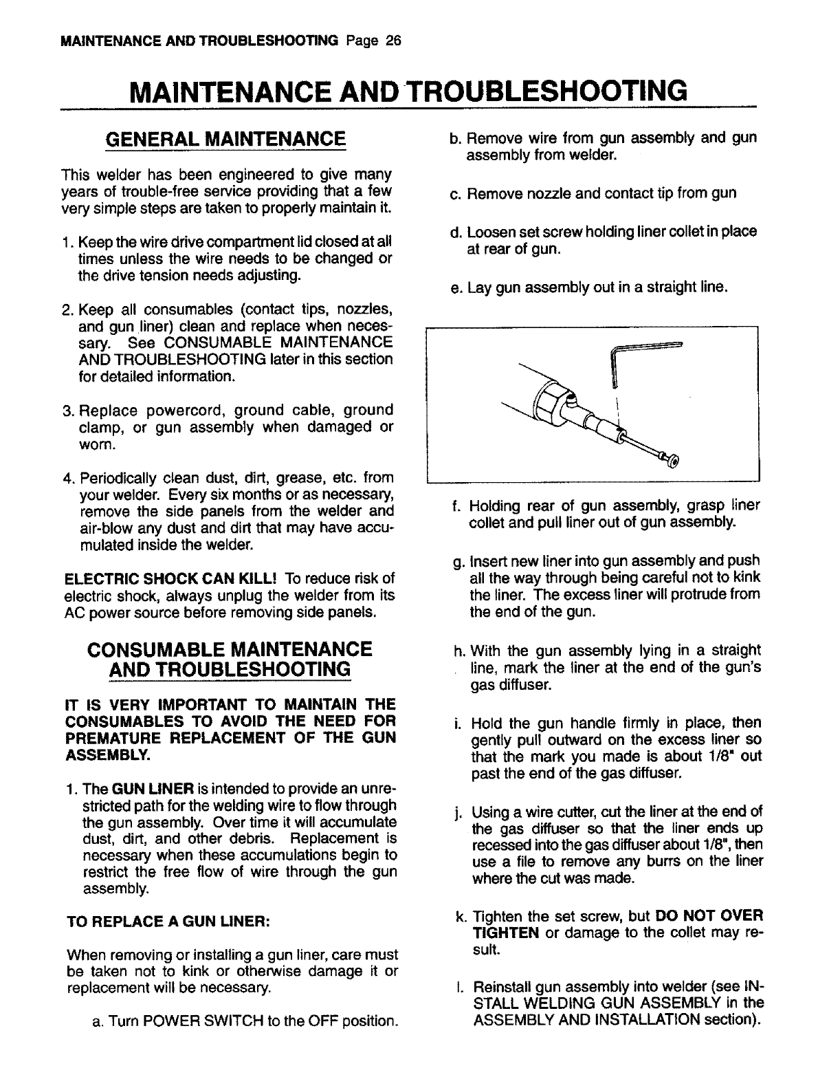
MAINTENANCE AND TROUBLESHOOTING Page 26
MAINTENANCE AND TROUBLESHOOTING
GENERAL MAINTENANCE
This welder has been engineered to give many
years of trouble-free service providing that afew
very simple steps are taken to properly maintain it.
1. Keep the wire drive compartment lid closed at all
times unless the wire needs to be changed or
the drive tension needs adjusting.
2. Keep all consumables (contact tips, nozzles,
and gun liner) clean and replace when neces-
sary. See CONSUMABLE MAINTENANCE
AND TROUBLESHOOTING later in this section
for detailed information.
3. Replace powercord, ground cable, ground
clamp, or gun assembly when damaged or
worn.
4. Periodically clean dust, dirt, grease, etc. from
your welder. Every six months or as necessary,
remove the side panels from the welder and
air-blow any dust and dirt that may have accu-
mulated inside the welder.
ELECTRIC SHOCK CAN KILL? To reduce risk of
electric shock, always unplug the welder from its
AC power source before removing side panels.
CONSUMABLE MAINTENANCE
AND TROUBLESHOOTING
IT IS VERY IMPORTANT TO MAINTAIN THE
CONSUMABLES TO AVOID THE NEED FOR
PREMATURE REPLACEMENT OF THE GUN
ASSEMBLY.
1. The GUN LINER is intended to provide an unre-
stricted path for the welding wire to flow through
the gun assembly. Over time it will accumulate
dust, dirt, and other debds. Replacement is
necessary when these accumulations begin to
restrict the free flow of wire through the gun
assembly.
TO REPLACE A GUN LINER:
When removing or installing a gun liner, care must
be taken not to kink or otherwise damage it or
replacement will be necessary.
a. Turn POWER SWITCH to the OFF position.
b. Remove wire from gun assembly and gun
assembly from welder.
c. Remove nozzle and contact tip from gun
d. Loosen set screw holding liner collet in place
at rear of gun.
e. Lay gun assembly out in a straight line.
f,
g°
h,
Holding rear of gun assembly, grasp liner
collet and pull liner out of gun assembly.
Insert new liner into gun assembly and push
all the way through being careful not to kink
the liner. The excess liner wilt protrude from
the end of the gun.
With the gun assembly lying in astraight
line, mark the liner at the end of the gun's
gas diffuser.
Hold the gun handle firmly in place, then
gently pull outward on the excess liner so
that the mark you made is about 118" out
past the end of the gas diffuser.
Using awire cutter, cut the liner at the end of
the gas diffuser so that the liner ends up
recessed into the gas diffuser about 1/8", then
use a file to remove any burrs on the liner
where the cut was made.
k. Tighten the set screw, but DO NOT OVER
TIGHTEN or damage to the collet may re-
sult.
1. Reinstall gun assembly into welder (see IN-
STALL WELDING GUN ASSEMBLY in the
ASSEMBLY AND INSTALLATION section).
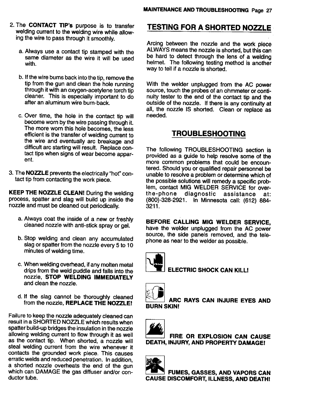
MAINTENANCE AND TROUBLESHOOTING Page 27
2. The CONTACT TIP's purpose is to transfer
welding current to the welding wire while allow-
ing the wire to pass through it smoothly.
a. Always use a contact tip stamped with the
same diameter as the wire it will be used
with.
b_ Ifthe wire burns back into the tip, remove the
tip from the gun and clean the hole running
through itwith an oxygen-acetylene torch tip
cleaner. This is especially important to do
after an aluminum wire burn-back.
C, Over time, the hole in the contact tip will
become worn by the wire passing through it.
The more worn this hole becomes, the less
efficient is the transfer of welding current to
the wire and eventually arc breakage and
difficult arc starting will result. Replace con-
tact tips when signs of wear become appar-
ent.
3. The NOZZLE prevents the electrically"hot" con-
tact tip from contacting the work piece.
KEEP THE NOZZLE CLEAN! During the welding
process, spatter and slag will build up inside the
nozzle and must be cleaned out periodically.
a. Always coat the inside of a new or freshly
cleaned nozzle with anti-stick spray or gel.
b. Stop welding and clean any accumulated
slag or spatter from the nozzle every 5 to 10
minutes of welding time.
C* When welding overhead, if any molten metal
drips from the weld puddle and falls into the
nozzle, STOP WELDING IMMEDIATELY
and clean the nozzle.
d. If the slag cannot be thoroughly cleaned
from the nozzle, REPLACE THE NOZZLE!
Failure to keep the nozzle adequately cleaned can
result in a SHORTED NOZZLE which results when
spatter build-up bridges the insulation in the nozzle
allowing welding current to flow through it as well
as the contact tip. When shorted, anozzle will
steal welding current from the wire whenever it
contacts the grounded work piece. This causes
erratic welds and reduced penetration. In addition,
a shorted nozzle overheats the end of the gun
which can DAMAGE the gas diffuser and/or con-
ductor tube.
TESTING FOR A SHORTED NOZZLE
Arcing between the nozzle and the work piece
ALWAYS means the nozzle is shorted, but this can
be hard to detect through the lens of a welding
helmet. The following testing method is another
way to tell if a nozzle is shorted.
With the welder unplugged from the AC power
source, touch the probes of an ohmmeter or conti-
nuity tester to the end of the contact tip and the
outside of the nozzle. If there is any continuityat
all, the nozzle IS shorted. Clean or replace as
needed.
TROUBLESHOOTING
The following TROUBLESHOOTING section is
provided as a guide to help resolve some of the
more common problems that could be encoun-
tered. Should you or qualified repair personnel be
unable to resolve a problem or determine which of
the possible solutions will remedy a specific prob-
lem, contact MIG WELDER SERVICE for over-
the-phone diagnostic assistance at:
(800)-328-2921. In Minnesota call: (612) 884-
3211.
BEFORE CALLING MIG WELDER SERVICE,
have the welder unplugged from the AC power
source, the side panels removed, and the tele-
phone as near to the welder as possible.
ELECTRIC SHOCK CAN KILL!
_ARC RAYS CAN INJURE EYES AND
BURN SKIN!
FIRE OR EXPLOSION CAN CAUSE
DEATH, INJURY, AND PROPERTY DAMAGE!
FUMES, GASSES, AND VAPORS CAN
CAUSE DISCOMFORT, ILLNESS, AND DEATH!
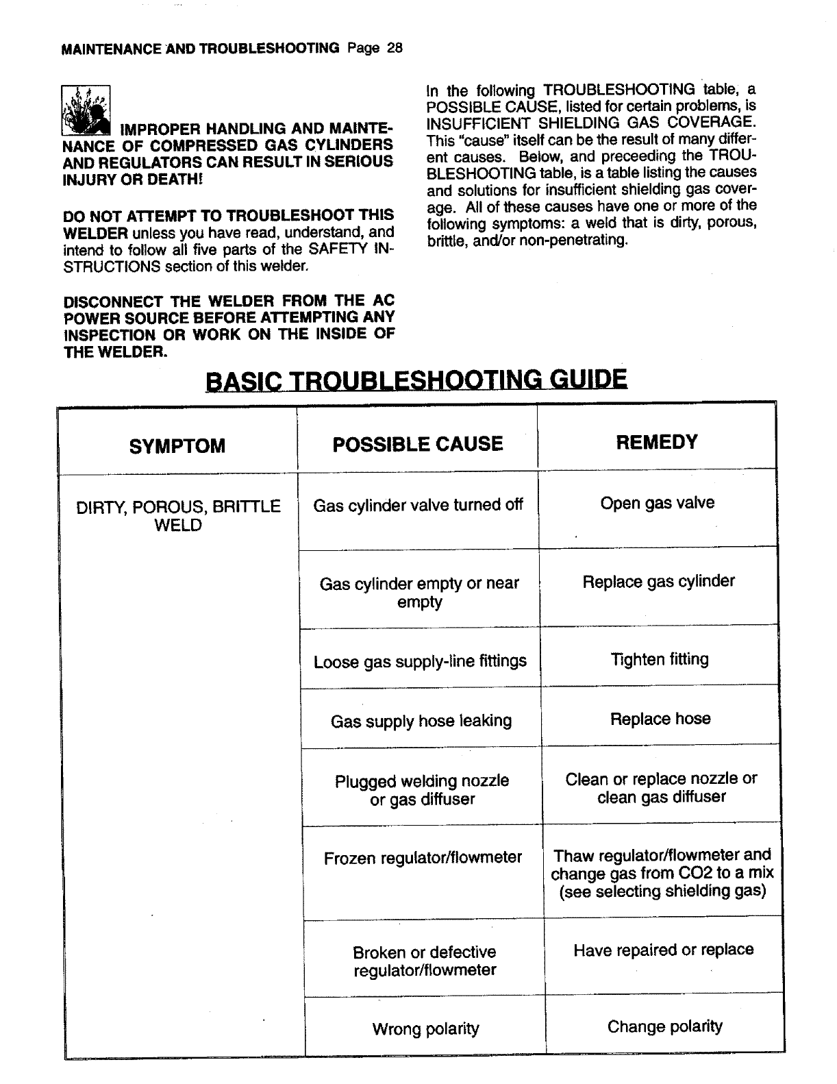
MAINTENANCE AND TROUBLESHOOTING Page 28
IMPROPER HANDLING AND MAINTE-
NANCE OF COMPRESSED GAS CYLINDERS
AND REGULATORS CAN RESULT IN SERIOUS
INJURY OR DEATH!
DO NOT ATTEMPT TO TROUBLESHOOT THIS
WELDER unless you have read, understand, and
intend to follow all five parts of the SAFETY IN-
STRUCTIONS section of this welder.
In the following TROUBLESHOOTING table, a
POSSIBLE CAUSE, listed for certain problems, is
INSUFFICIENT SHIELDING GAS COVERAGE.
This "cause" itself can be the result of many differ-
ent causes. Below, and preceeding the TROU-
BLESHOOTING table, is a table listing the causes
and solutions for insufficient shielding gas cover-
age. All of these causes have one or more of the
following symptoms: a weed that is dirty, porous,
brittle, and/or non-penetrating.
DISCONNECT THE WELDER FROM THE AC
POWER SOURCE BEFORE A'I'rEMPTING ANY
INSPECTION OR WORK ON THE INSIDE OF
THE WELDER.
SYMPTOM
BASIC TROUBLESHOOTING GUIDE
POSSIBLE CAUSE
Gas cylinder valve turned off
Gas cylinder empty or near
empty
Loose gas supply-line fittings
Gas supply hose leaking
Plugged welding nozzle
or gas diffuser
Frozen regulator/flowmeter
Broken or defective
regulator/flowmeter
Wrong polarity
DIRTY, POROUS, BRITTLE
WELD
REMEDY
Open gas valve
Replace gas cylinder
Tighten fitting
Replace hose
Clean or replace nozzle or
clean gas diffuser
Thaw regulator/flowmeter and
change gas from CO2 to a mix
(see selecting shielding gas)
Have repaired or replace
Change polarity
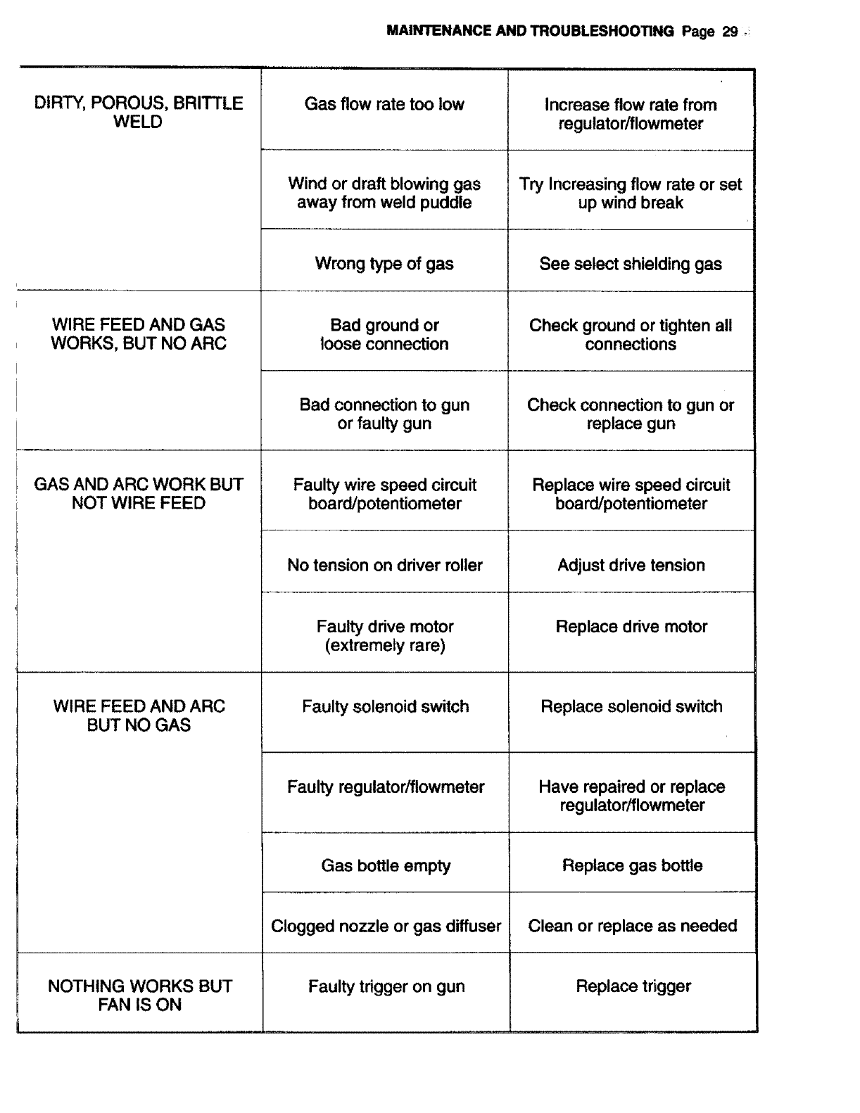
MAINTENANCE AND TROUBLESHOOTING Page 29
ii
DIRTY, POROUS, BRITTLE
WELD Gas flow rate too low
WIRE FEED AND GAS
WORKS, BUT NO ARC
GAS AND ARC WORK BUT
NOT WIRE FEED
WIRE FEED AND ARC
BUT NO GAS
NOTHING WORKS BUT
FAN IS ON
Wind or draft blowing gas
away from weld puddle
Wrong type of gas
Bad ground or
loose connection
Bad connection to gun
or faulty gun
Faulty wire speed circuit
board/potentiometer
No tension on driver roller
Faulty drive motor
(extremely rare)
Faulty solenoid switch
Faulty regulator/fiowmeter
Gas bottle empty
Clogged nozzle or gas diffuser
Faulty trigger on gun
Increase flow rate from
regutator/flowmeter
Try Increasing flow rate or set
up wind break
See select shielding gas
Check ground or tighten all
connections
Check connection to gun or
replace gun
Replace wire speed circuit
board/potentiometer
Adjust drive tension
Replace drive motor
Replace solenoid switch
Have repaired or replace
regulator/flowmeter
Replace gas bottle
Clean or replace as needed
Replace trigger
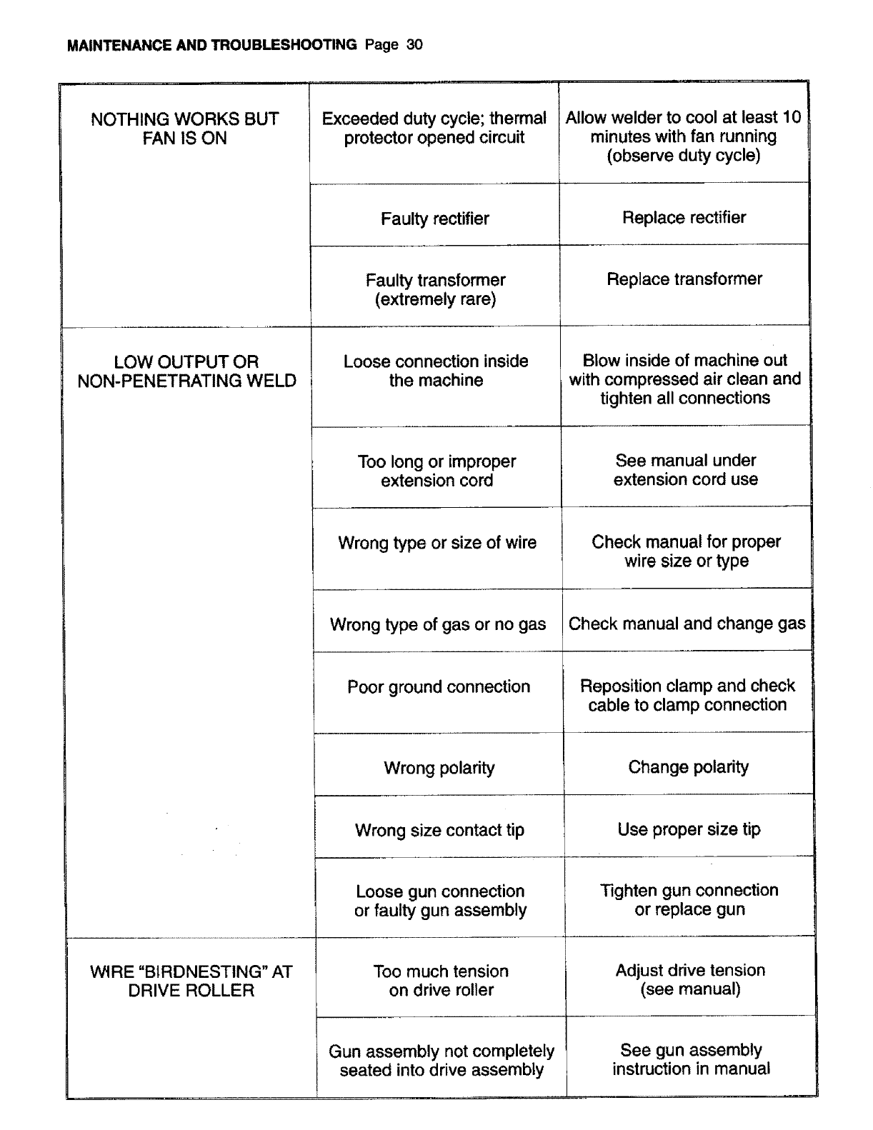
MAINTENANCE AND TROUBLESHOOTING Page 30
NOTHING WORKS BUT
FAN IS ON
LOW OUTPUT OR
NON-PENETRATING WELD
WtRE "BIRDNESTING" AT
DRIVE ROLLER
Exceeded duty cycle; thermal
protector opened circuit
Faulty rectifier
Faulty transformer
(extremely rare)
Loose connection inside
the machine
Too long or improper
extension cord
Wrong type or size of wire
Wrong type of gas or no gas
Poor ground connection
Wrong polarity
Wrong size contact tip
Loose gun connection
or faulty gun assembly
Too much tension
on drive roller
Gun assembly not completely
seated into drive assembly
i ii ir
Allow welder to cool at least 10
minutes with fan running
(observe duty cycle)
Replace rectifier
Replace transformer
Blow inside of machine out
with compressed air clean and
tighten all connections
See manual under
extension cord use
Check manual for proper
wire size or type
Check manual and change gas
Reposition clamp and check
cable to clamp connection
Change polarity
Use proper size tip
Tighten gun connection
or replace gun
Adjust drive tension
(see manual)
See gun assembly
instruction in manual
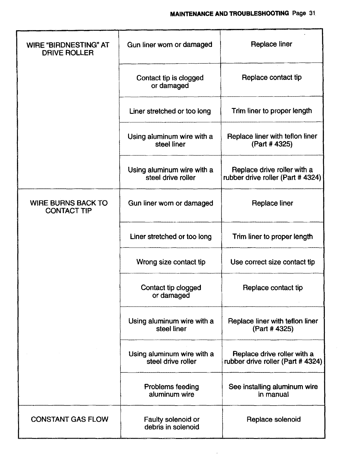
WIRE "BIRDNESTING" AT
DRIVE ROLLER
WIRE BURNS BACK TO
CONTACT TIP
CONSTANT GAS FLOW
MAINTENANCE AND TROUBLESHOOTING Page 31
..... illlllll iii ....... i i
Contact tip is clogged
or damaged
Liner stretched or too long
Using aluminum wire with a
steel liner
Using aluminum wire with a
steel drive roller
Gun liner worn or damaged
Liner stretched or too long
Wrong size contact tip
Contact tip clogged
or damaged
Using aluminum wire with a
steel liner
Using aluminum wire with a
steel drive roller
Problems feeding
aluminum wire
Faulty solenoid or
debris in solenoid
Replace contact tip
Trim liner to proper length
Replace liner with teflon liner
(Part # 4325)
Replace drive roller with a
rubber drive roller (Part #4324)
Trim liner to proper length
Use correct size contact tip
Replace contact tip
Replace liner with teflon liner
(Part # 4325)
Replace ddve roller with a
rubber drive roller (Part # 4324)
See installing aluminum wire
in manual
Replace solenoid
Replace liner
Replace liner
Gun liner worn or damaged
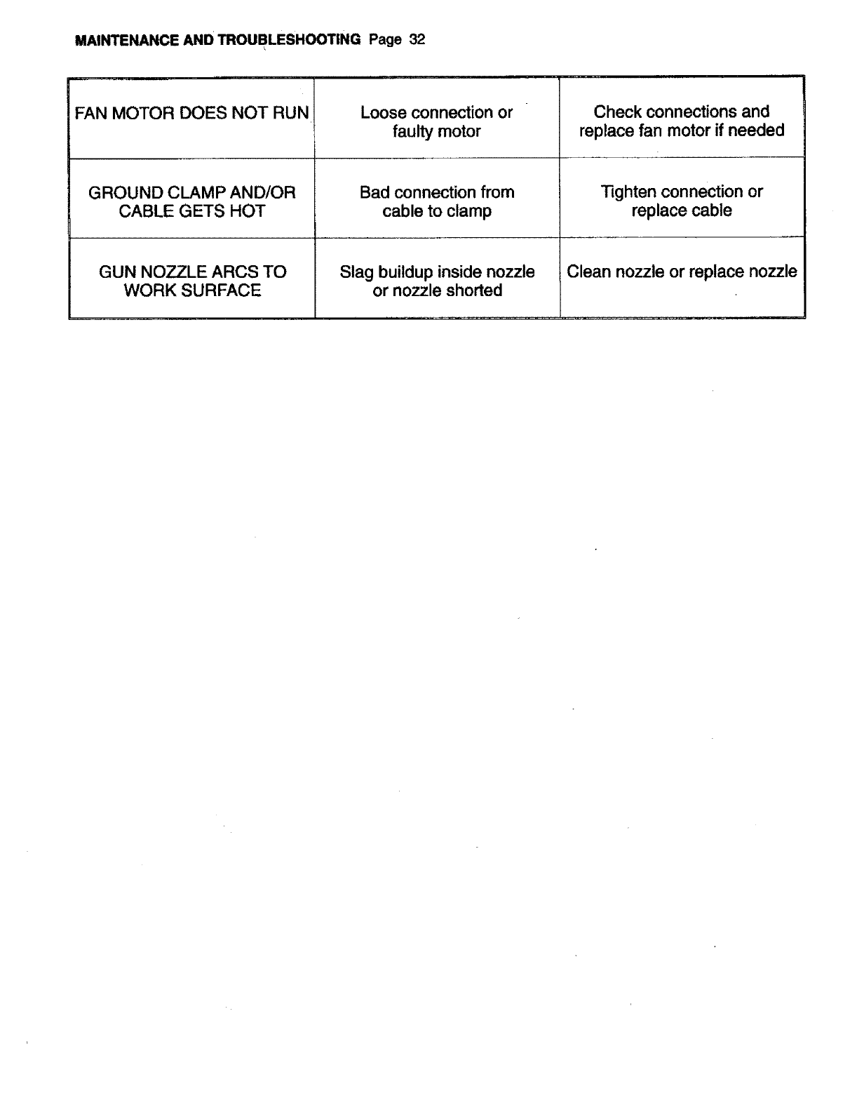
MAINTENANCE AND TROUBLESHOOTING Page 32
FAN MOTOR DOES NOT RUN Loose connection or
faulty motor
Bad connection from
cable to clamp
= = = =llll,
Check connections and
replace fan motor if needed
Tighten connection or
replace cable
GROUND CLAMP AND/OR
CABLE GETS HOT
GUN NOZZLE ARCS TO Slag buildup inside nozzle Clean nozzle or replace nozzle
WORK SURFACE or nozzle shorted
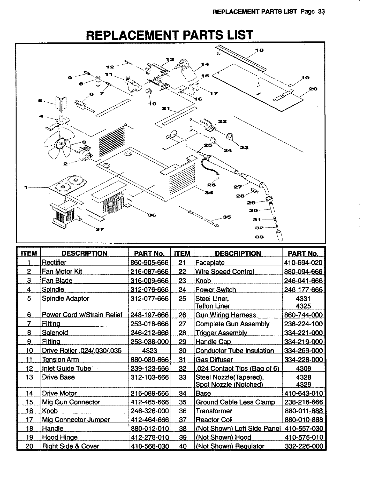
REPLACEMENT PARTS LIST Page 33
REPLACEMENT PARTS LIST
10
ii i iin i
ITEM DESCR|!_TION
1 Rectifier
2 Fan Motor Kit
3 Fan Blade
4 Sjoindle
5 Spindle Adaptor
6 Power Cord w/Strain Relief
7Fitting _,
8 Solenoid
..........9 Fitting ......
10 Drive Roller ,Q24/03,0/.035
11 Tension Arm
12 Inlet Guide Tube
13 Drive Base
14 Drive Motor
15 Mig Gun Connector
16 Knob
17 Mig Connector Jumper
18 Handle
19 Hood Hinge
20 Right Side & Cover
PART No. ITEM
860-905-666 21
216-087-666 22
316-009-666 23
312-076-666 !24
312-077-666 25
248-197-666 26
253-018-666 27
246-212-666 28
253-038-000 29
4323 30
880-089-666 31
239-123-666 32
312-103-666 33
216-089-666 34
412-465-666 35
246-326-000 36
412-464-666 37
880-012-010 38
412-278-010 39
410-568-030 40
DESCRIPTION
Faceplate
Wire Speed Control
Knob
Power Switch
Steel Uner,
Teflon Uner
Gun Wiring Harness
Complete Gun Assembly
TriQaer Assembly
Handle Cap
Conductor Tube Insulation
iGas Diffuser
.024 Contact liDS (Bag of 6)
Steel Nozzle(Tapered),
Spot Nozzle (.Notched.)
Base
Ground Cable Less Clamp
Transformer
Reactor Coil
PART No.
410-694-020
880-094-666
246-041-666
246-177-6_
433t
4325
860-744-000
238-224-100
334-221-000
334-219-000
334-269-000
334-228-000
4309
4328
4329
410-643-010
238-216-666
880-011-888
880-010-888
(Not Shown) Left Side Panel 410-557-030
(Not Shown) Hood 410-575-010
(Not Shown) Regulator 332-226-000
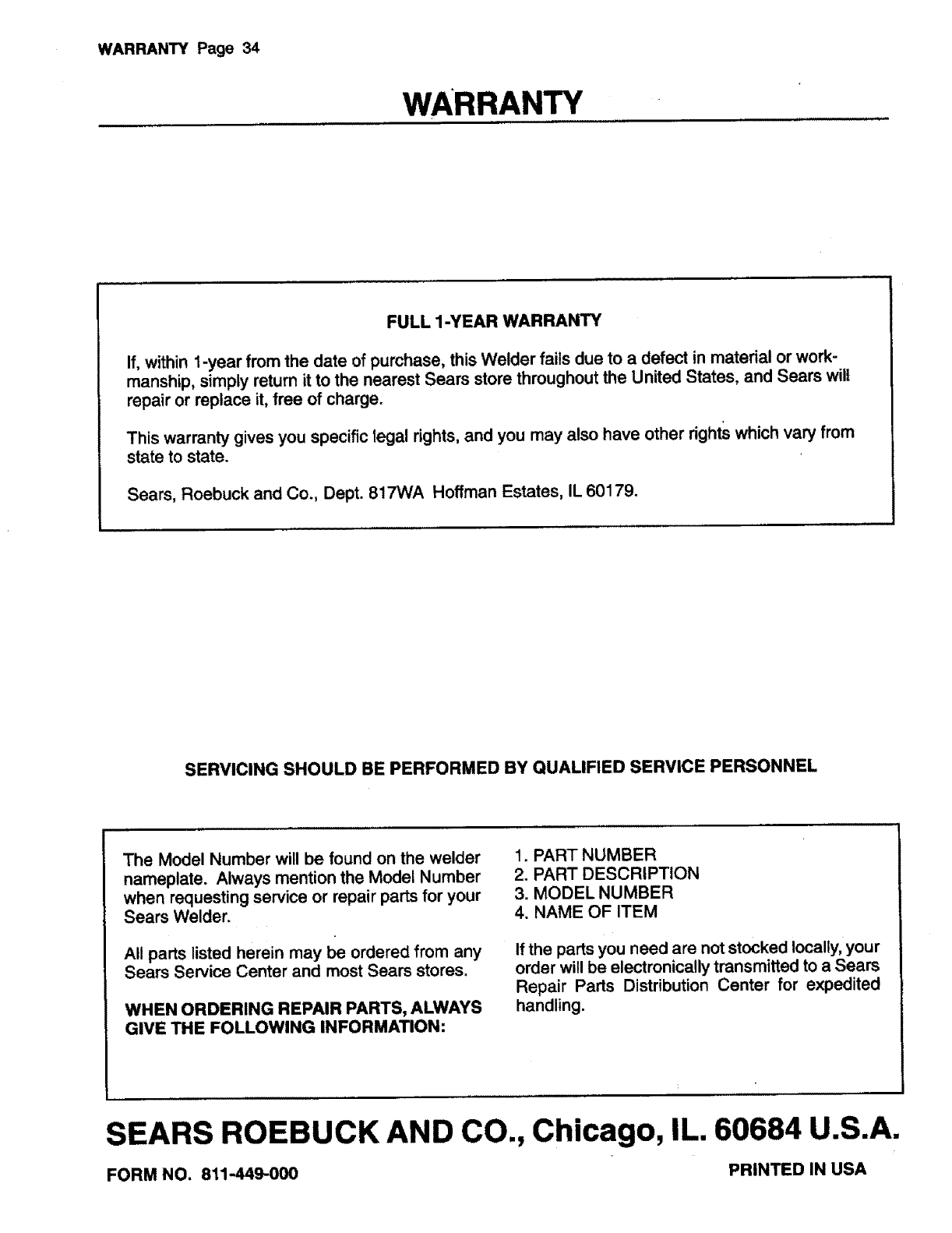
WARRANTY Page 34
WARRANTY
FULL 1-YEAR WARRANTY
If, within 1-year from the date of purchase, this Welder fails due to a defect in material or work-
manship, simply return it to the nearest Sears store throughout the United States, and Sears wilt
repair or replace it, free of charge.
This warranty gives you specific legal rights, and you may also have other rights which vary from
state to state.
Sears, Roebuck and Co., Dept. 817WA Hoffman Estates, IL 60179.
SERVICING SHOULD BE PERFORMED BY QUALIFIED SERVICE PERSONNEL
The Model Number will be found on the welder
nameplate. Always mention the Model Number
when requesting service or repair parts for your
Sears Welder.
All parts listed herein may be ordered from any
Sears Service Center and most Sears stores.
WHEN ORDERING REPAIR PARTS, ALWAYS
GIVE THE FOLLOWING INFORMATION:
1. PART NUMBER
2. PART DESCRIPTION
3. MODEL NUMBER
4. NAME OF ITEM
If the parts you need are not stocked locally, your
order will be electronically transmitted to aSears
Repair Parts Distribution Center for expedited
handling.
SEARS ROEBUCK AND CO., Chicago, IL. 60684 U.S.A.
FORM NO. 811-449-000 PRINTED IN USA
