Craftsman 944609810 User Manual LAWN TRACTOR Manuals And Guides 99020015
CRAFTSMAN Lawn, Tractor Manual 99020015 CRAFTSMAN Lawn, Tractor Owner's Manual, CRAFTSMAN Lawn, Tractor installation guides
User Manual: Craftsman 944609810 944609810 CRAFTSMAN LAWN TRACTOR - Manuals and Guides View the owners manual for your CRAFTSMAN LAWN TRACTOR #944609810. Home:Lawn & Garden Parts:Craftsman Parts:Craftsman LAWN TRACTOR Manual
Open the PDF directly: View PDF ![]() .
.
Page Count: 56

SEAR8
OWNER'S
MANUAL
MODEL NO.
944.609810
Caution:
Read and follow
all Safety Rules
and Instructions
Be.fore Operating
Thin Eqmpment
I:RRFTSMRN
20 HP
ELECTRIC START
46" MOWER
AUTOMATIC
LAWN TRACTOR
•Assembly
•Operation
•Customer Responsibilities
•Service and Adjustments
•Repair Parts
Sears Canada, Inc., Toronto, Ontario M5B 2B8
SAFETY RULES
Safe Operation Practices for Ride-On Mowers
IMPORTANT: THIS CU'I-rlNG MACHINE IS CAPABLE OF AMPUTATING HANDS AND FEET AND THROWING
OBJECTS. FAILURE TO OBSERVE THE FOLLOWING SAFETY INSTRUCTIONS COULD RESULT IN SERIOUS
INJURY OR DEATH.
I. GENERAL OPERATION
•Read, understand,and followall instructionsinthe manual
and on the machine beforestarting.
Only allow responsibleadults,who are familiar with the
instructions,to operatethe machine.
Clear the area of objectssuch as rocks,toys, wire, etc.,
whichcouldbe picked up andthrownby the blade.
•Besurethe areaisclearofotherpeoplebeforemowing.Stop
machineif anyone entersthe area.
Nevercany passengers.
Donotmowinreverseunlessabsolutelynecessary.Always
lookdownand behindbeforeandwhilebacking.
•Be aware ofthe mowerdischargedirectionanddonotpoint
it at anyone. Do notoperate the mowerwithouteitherthe
entiregrasscatcheror the guardinplace.
Slowdownbeforeturning.
•Neverleavea runningmachineunattended.Alwaystum off
blades,set parkingbrake, stopengine, and remove keys
beforedismounting.
•Turnoff blades when notmowing.
Stop engine before removinggrasscatcheror unclogging
chute.
•Mow onlyindaylightorgoodartificiallight.
•Do not operate the machinewhile underthe influenceof
alcoholor drugs,
Watchfortrafficwhenoperatingnearorcrossingroadways.
Use extracare whenloadingor unloadingthe machineinto
a trailerortruck.
IL SLOPE OPERATION
Slopes are a major factor related to loss-of-control and tipover
accidents, which can result in severe injury or death. All slopes
require extra caution, ifyou cannot back up the slope or ifyou feel
uneasy on it, do not mow it.
DO:
Mow up and down elopes, not across.
Remove obstacles such as rocks, tree limbs, etc.
•Watch for holes, ruts, or bumps. Uneven terrain could
overturn the machine. Tall grass can hide obstacles.
•Use slowspeed. Choose alow gear so that you will not have
to stop or shift while on the slope,
•Follow the manufacturer's recom_nandations for wheel
weights or counterweights to improve stability.
•Use extra care with grass catchers or other attachments.
These can change the stability of the machine.
Keep all movement on the slopes slowand gradual Do not
make sudden changes in speed or direction.
•Avoid starting or stopping on a slope. If tires lose traction,
disengage the blades and proceed slowly straightdown the
slope.
DO NOT:
• Donotturnonslopesunlessnocessary, andthen, tumslowly
and gradually downhill, if possible.
•Do not mow near drop-offs, ditches or embankments. The
mower could suddenly turn over if awheel is over the edge
of a cliff or ditch, or if an edge caves in.
Do not mow on wet grass. Reduced traction could cause
sliding.
•Donottrytostabilizethemachinebyputtingyourfootonthe
ground.
•Do not t4segrass catcher on steep slopes. 2
IlL CHILDREN
Tragic accidents can occur if the operator is not alert to the
presence of children. Children are often attracted to the machine
and the mowing activity. Neverassume that children will remain
where you last saw them.
Keep childrenout of the mowing area and under the watchful
care of another responsible adult.
Be alert and turn machine off ifchildren enter the area.
Before and when backing, look behind and down for small
children.
•Never carry children. They may fall off and be seriously
injured or interfere with safe machine operation.
Never allow children to operate the machine.
Use extra care when approaching blind corners, shrubs,
trees, or other objects that may obscure vision.
IV. SERVICE
Use extra care inhandling gasoline and other fuels. They are
flammable and vapors are explosive.
Use only an approved container.
Never remove gas cap or add fuel with the engine
running. Allow engine to cool before refueling. Do not
smoke.
Never refuel the machine indoors,
Never store the machine or fuel container inside where
there is an open flame, such as a water heater.
Never run a machine inside a closed area.
•Keep nutsand bolts, especiatly blade attachment bolts, tight
and keep equipment in good condition.
Never tamper with safety devices. Check their proper
operation regulady.
Keep machine free of grass, leaves, or other debris build-up.
Clean oil or fuel spillage. Allow machine to cool before
storing.
•Stop and inspect the equipment if you strike an object.
Repair, if necessary, before restarting.
Never make adjustments or repairs with the engine running,
Grass catcher components are subject towear, damage, and
deterioration, which could expose moving parts or allow
objects to be thrown. Frequently check components and
replace with manufacturer's recommended pads, when nec-
essary.
•Mower blades are sharp and can cut. Wrap the blade(s) or
wear gloves, and use extra caution when servicing them.
Check brake operation frequently. Adjust and service as
required.
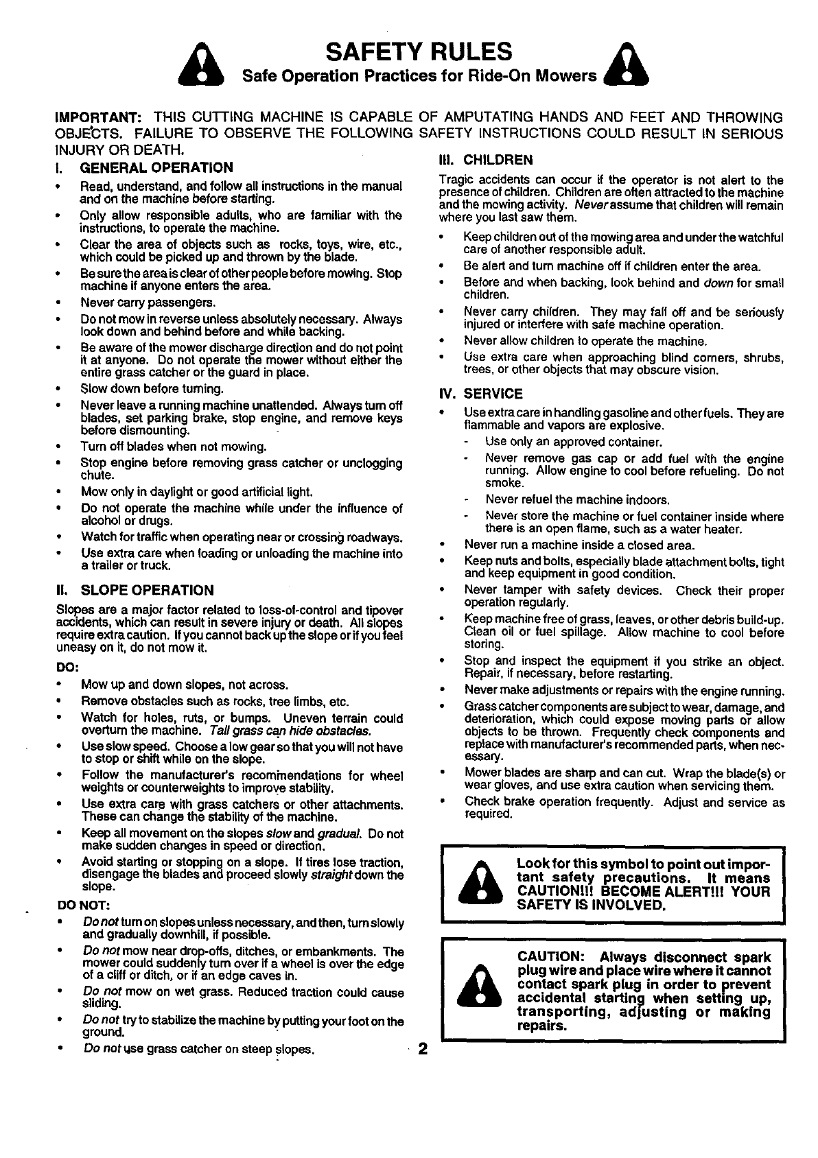
I& Look for this symbol to point out impor- I
tant safety precautions. It means
CAUTIONiH BECOME ALERT!i! YOUR
SAFETY IS INVOLVED.
&CAUTION: Always disconnect spark
plug wire and place wire where it cannot
contact spark plug in order to prevent
accidental startin|l when setting up,
transporting, adjusting or making
repairs.
CONGRATULATIONS on your purchase of a Sears
Tractor. It has been designed, engineered and manufac-
tured to give you the best possible dependability and
performance.
Should you experience any problem you cannot easily
remedy, please contact your nearest Sears Authorized
Service Centre/Department We have competent, well-
trained technicians and the proper tools to service or repair
this tractor.
Please read and retain this manual. The instructions will
enable you to assemble and maintain your tractor properly.
Always observe the =SAFETY RULES".
MODEL
NUMBER 944.609810
SERIAL
NUMBER
DATEOFPURCHASE
THEMODELANDSERIALNUMBERSWILLBEFOUND
ON A PLATE UNDER THE SEAT,
YOUSHOULDRECORDBOTHSERIALNUMBERAND
DATE OF PURCHASE AND KEEP IN A SAFE PLACE
FOR FUTURE REFERENCE.
MAINTENANCE AGREEMENT
A Sears Maintenance Agreement is available on this prod-
uct. Contact your nearest Sears store for details.
CUSTOMER RESPONSIBILITIES
Read and observe the safety rules.
•Followa regular schedule in maintaining,caring for and
using your tractor.
•Follow the instructions under"Customer Responsibili-
ties" and "Storage" sections of this owner's manual,
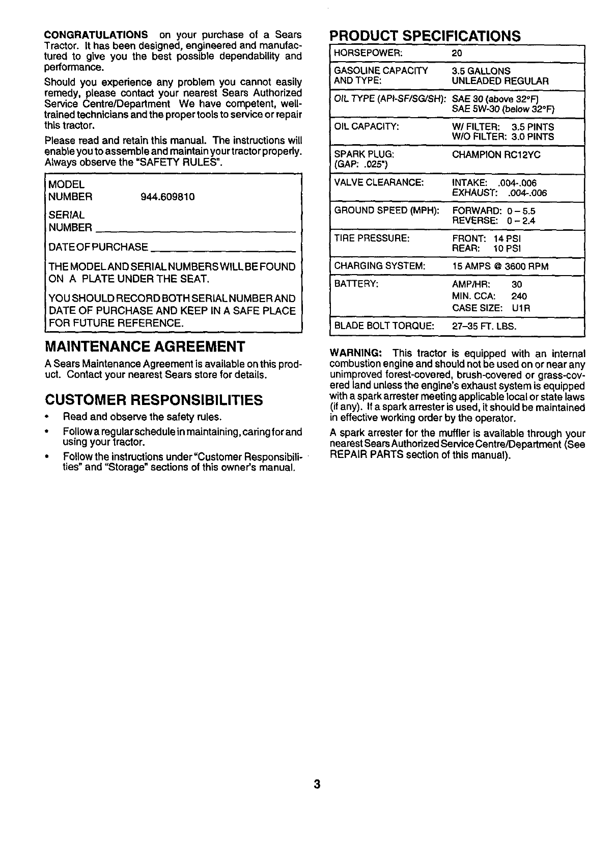
PRODUCT SPECIFICATIONS
HORSEPOWER: 20
GASOLINE CAPACITY 3.5 GALLONS
AND TYPE: UNLEADED REGULAR
OIL TYPE (API-SF/SG./SH): SAE 30 (above 32°F)
SAE 5W.30 (below 32°F)
OIL CAPACITY: W/FILTER: 3.5 PINTS
W/O FILTER: 3.0 PINTS
SPARK PLUG: CHAMPION RC12YC
GAP: .025")
VALVE CLEARANCE: INTAKE: .004-.006
EXHAUST: .004-.006
GROUND SPEED (MPH): FORWARD: 0- 5.5
REVERSE: 0-2.4
TIRE PRESSURE: FRONT: 14 PSI
REAR: 10 PSI
CHARGINGSYSTEM: 15 AMPS @3600 RPM
BATTERY: AMP/HR: 30
MIN. CCA: 240
CASE SIZE: UlR
BLADE BOLT TORQUE: 27-35 FT. LBS.
WARNING: This tractor is equipped with an internal
combustion engine and should not be used on or near any
unimproved forest-covered, brush-covered or grass-cov-
ered land unless the engine's exhaust system is equipped
with a spark arrester meeting applicable local or state laws
(if any). If a spark arrester is used, it should be maintained
in effective working order by the operator.
A spark arrester for the muffler is available through your
nearestSears AuthorizedService Centre/Department (See
REPAIR PARTS section of this manual).
3
TABLE OF CONTENTS
SAFETY RULES ............................................................ 2
PRODUCT SPECIFICATIONS ...................................... 3
cuSTOMER RESPONSIBILITIES ..................... 3, 16-19
WARRANTY .................................................................. 4
ASSEMBLY ........................................................... ,... 6-9
OPERATION ........................................................... 10-15
MAINTENANCE SCHEDULE ...................................... 16
SERVICE AND ADJUSTMENTS ............................ 20-25
STORAGE ................................................................... 26
TROUBLESHOOTING ............................................ 27-28
REPAIR PARTS -TRACTOR ................................. 30-47
REPAIR PARTS -ENGINE .................................... 48-52
PARTS ORDERING/SERVICE ................ BACK COVER
WARRANTY
LIMITED TWO (2) YEAR WARRANTY ON CRAFTSMAN TRACTOR (RIDING EQUIPMENT)
ForTwo (2) years fromdate of purchaseSears Canada,Inc. willrepairorreplaceat Sears optionfree ofchargepartswhichare
defectiveas a resultof materialorworkmanship.
FULL ONE (1) YEAR WARRANTY ON BATTERY
For One (1) year from date of purchase, if any batteryincludedwith this ridingequipmentproves defectivein materialor
workmanshipandourtestingdeterminesthebatterywillnotholda charge,Searswill replacethe batteryat nocharge.
COMMERCIAL OR RENTAL USE
WarrantyonRidingEquipmentusedforcommercialorrentalpurposes is limited to ninety (90) days.
This Warranty does NOT cover:
1. Pre-dellvery set-up.
2. Tire replacement or repair caused by puncturesfrom outside objects (such as nails,thorns, stumps, or glass).
3. Expendable Items which become worn during normal use,such as blades, spark plug, sir cleaners end belts.
4. Repairs necessary because of operator abuse or negligence, including damaged jeokshaft or mandrel end the
failure to operate and maintain the equipment accordingto the Instructions contained In the Owner's Manual,
5. In Home service.
Warranty service is available by returning the Craftsman Riding Equipment to the nearest Sears Service Cantre/Depadmant in
Canada. This warranty applies only while this product is in use in Canada.
This warranty is in addition to any statutory warranty and does not exclude or limit legal rights you may have but shall run
concurrently with applicable provincial legislation. Furthermore, some provinces do NOT allow limitation on how long an implied
warranty will last so the above limitationsmay not apply to you.
SEARS CANADA, INC., TORONTO, ONTARIO M5B 2B8
4
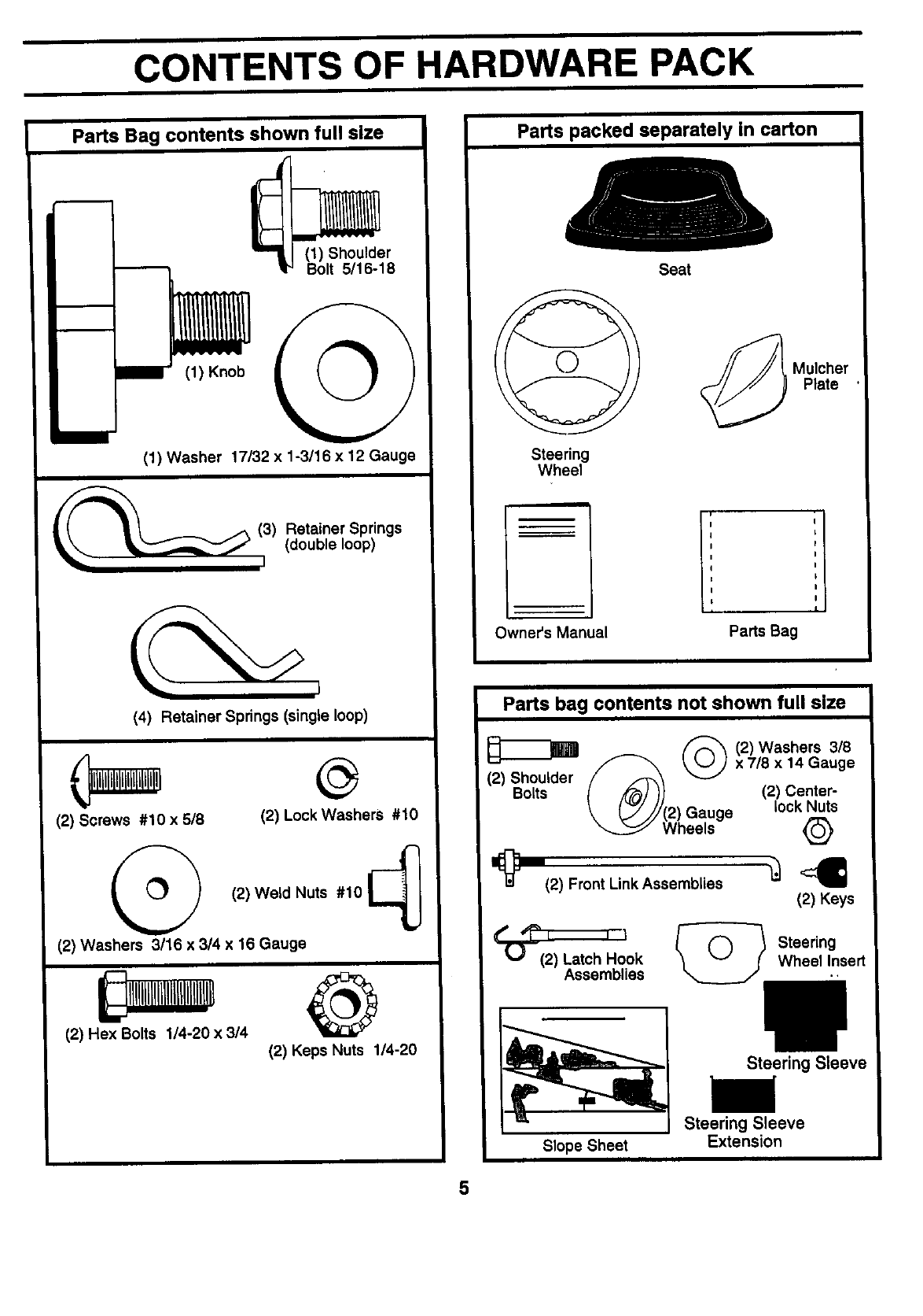
CONTENTS OF HARDWARE PACK
Parts Bag contents shown full slze
_) Shoulder
olt 5116-18
(1) Knob
(1) Washer 17/32 x 1-3/16 x 12 Gauge
(3) etainer Springs
(double loop)
(4) Retainer Springs (single loop)
(2) Screws #10 x 518 (2) Lock Washers #10
(2) Weld Nuts #10
(2) Washers 3/16 x 3/4 x 16 Gauge
(2) Hex Bolts 114-20 x 3/4 @
(2) Keps Nuts 1/4-20
Parts packed separately in carton
Steering
Wheel
m
Owner's Manual
Seat
_Mulcher
Plate
I; "1
IL
I
I
I
I
I
I
Parts Bag
Parts bag contents not shown full size
(2) Shoulder
Bolts
(2) Washers 3/8
x 7/8 x 14 Gauge
(2) Center-
Gauge lock Nuts
Wheels Q
1_(2) Front Link Assemblies _<_
(2) Keys
t" -_'t t I _ Steedng
U (2) Latch Hook Wheel Insert
Assemblies .,
Slope Sheet
Steering Sleeve
l/
Steering Sleeve
Extension
5
ASSEMBLY
Your new tractor has been assembled at the factory with exception of those parts left unassembled for shipping purposes.
To ensure safe and proper operation of your tractor all parts and hardware you assemble must be tightened securely. Use
the correct tools as necessary to insure proper tightness.
TOOLS REQUIRED FOR ASSEMBLY
A socket wrench set will make assembly easier. Standard
wrench sizes are listed.
(2) 7/16" wrenches
(1) 9/16" wrench
(1) 1/2" wrench
(1) Pliers
(1) Tire pressure gauge
(1) Utility knife
(1) 3/4" socket w/drive ratchet
(1) 3/4" wrench
When right or left hand is mentioned in this manual, it
means when you are in the operating position (seated
behind the steering wheel).
TO REMOVE TRACTOR FROM CARTON
UNPACK CARTON
•Remove all accessible loose parts and parts cartons
from carton (See page 5).
•Cut, from top to bottom, along lines on all four corners
of carton, and lay panels flat.
•Remove mower and packing materials.
•Check for any additional loose parts or cartons and
remove.
BEFORE ROLLING TRACTOR OFF
SKID
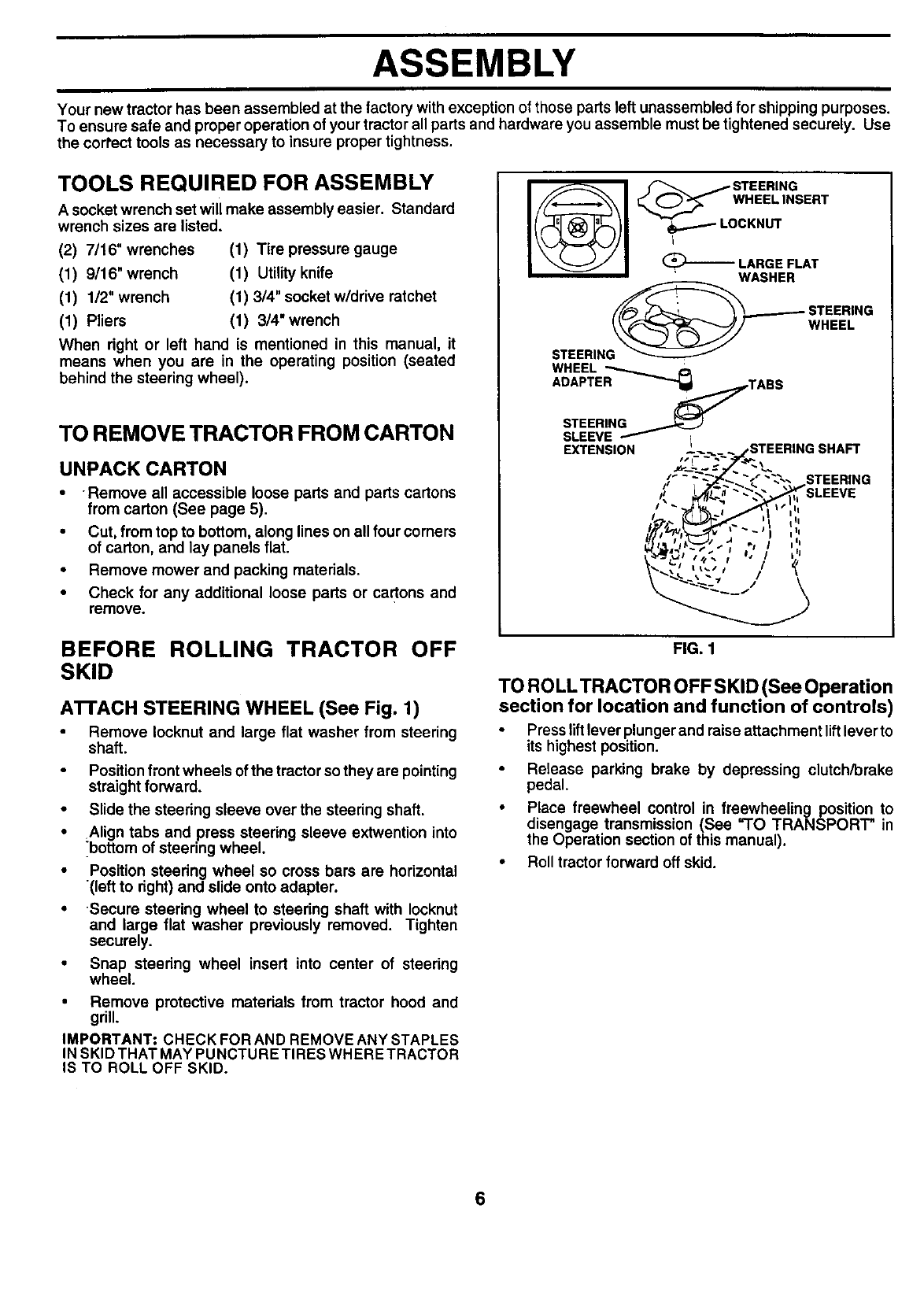
ATrACH STEERING WHEEL (See Fig. 1)
•Remove Iocknut and large flat washer from steering
shaft.
Position front wheels of the tractor so they are pointing
straight forward.
•Slide the steering sleeve over the steering shaft.
•Align tabs and press steering sleeve extwention into
_bottom of steering wheel.
•Position steering wheel so cross bars are horizontal
(left to right) and slide onto adapter.
•-Secure steering wheel to steering shaft with Iocknut
and large flat washer previously removed. Tighten
securely.
•Snap steering wheel insert into center of steering
wheel.
•Remove protective materials from tractor hood and
grill.
IMPORTANT: CHECK FOR AND REMOVE ANY STAPLES
IN SKID THAT MAY PUNCTURE TIRES WHERE TRACTOR
IS TO ROLL OFF SKID.
WHEEL INSERT
CKNUT
LARGE FLAT
WASHER
___-_ STEERING
STEERING _____ WHEEL
WHEEL _
ADAPTER _b!_TABS
EXTENSION _= _jSTEERING SHAFT
,--- STEER,.O
!_ I II
i-,_,_,_- _li ,',t
#7,"_,,_---_,_J "") ,',t
_'-'_.,.i". I 4, ,,,
FIG. 1
TO ROLL TRACTOR OFF SKID (See Operation
section for location and function of controls)
•Press liftlever plunger and raise attachment liftlever to
its highest position.
Release parking brake by depressing clutch/brake
pedal.
•Place freewheel control in freewheeling position to
disengage transmission (See "TO TRANSPORT" in
the Operation section of this manual).
•Roll tractor forward oft skid.
6
ASSEMBLY
HOW TO SET UP YOUR TRACTOR
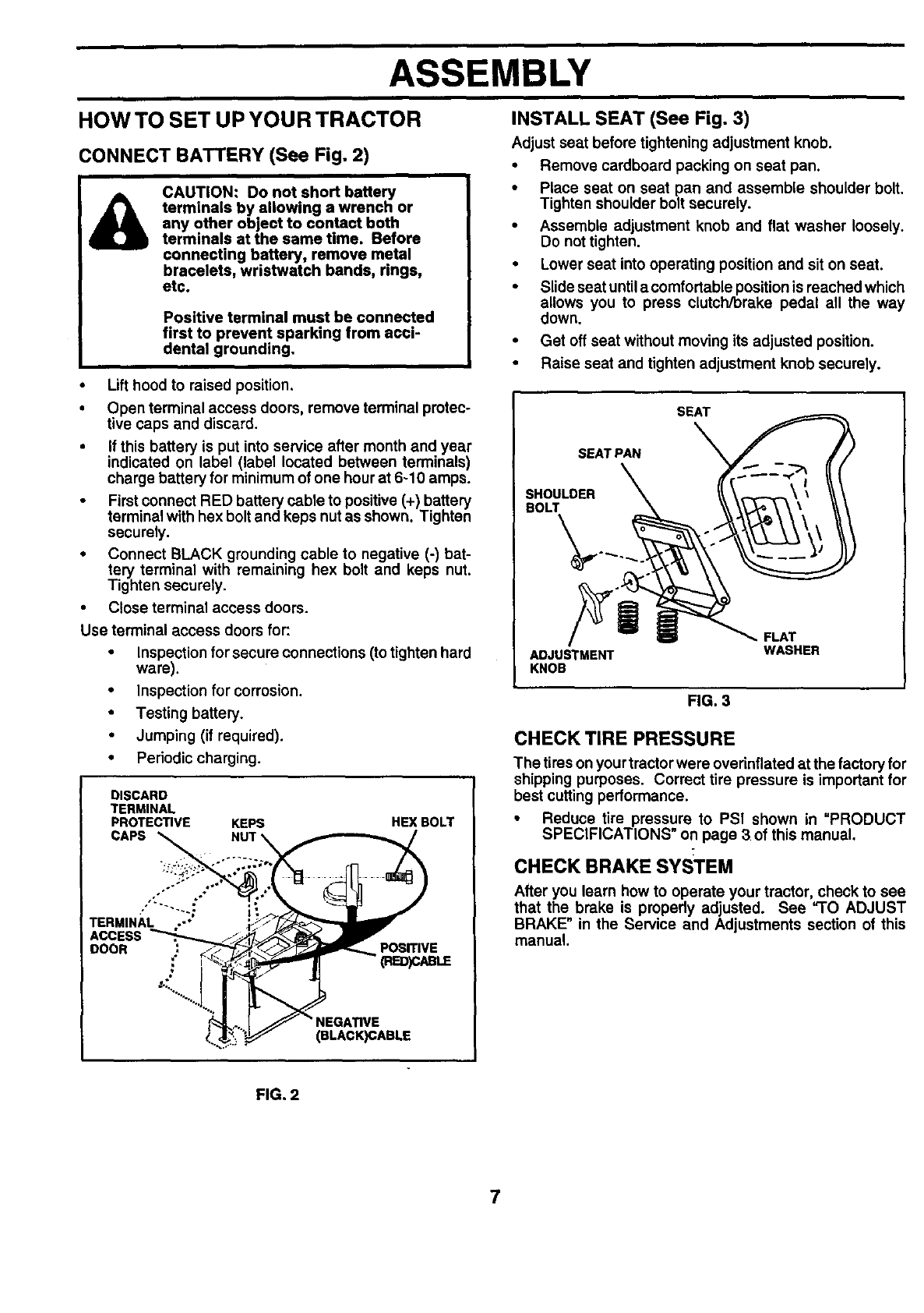
CONNECT BATTERY (See Fig. 2)
&CAUTION: Do not short battery
terminals by allowing a wrench or
any other object to contact both
terminals at the same time. Before
connecting battery, remove metal
bracelets, wristwatch bands, rings,
etc.
Positive terminal must he connected
first to prevent sparking from acci-
dental grounding.
• Lift hood to raised position.
• Open terminal access doors, remove terminal protec-
tive caps and discard.
•If this battery is put into service after month and year
indicated on label (label located between terminals)
charge battery for minimum of one hourat 6-10 amps.
•First connect RED battery cable to positive (+) battery
terminal with hex bolt and keps nut as shown• Tighten
securely.
•Connect BLACK grounding cable to negative (-) bat-
tery terminal with remaining hex bolt and keps nut.
Tighten securely•
•Close terminal access doors.
Use terminal access doors for:
•Inspection forsecure connections (totighten hard
ware).
•Inspection for corrosion.
•Testing battery.
•Jumping (if required).
•Periodic charging.
DISCARD
TERMINAL
PROTECTIVE
CAPS
KEPS HEX BOLT
PosmvE
(BLACK)CABLE
INSTALL SEAT (See Fig. 3)
Adjust seat before tightening adjustment knob.
•Remove cardboard packing on seat pan.
•Place seat on seat pan and assemble shoulder bolt.
Tighten shoulder bolt securely.
•Assemble adjustment knob and flat washer loosely.
Do not tighten,
•Lower seat into operating position and sit on seat.
•Slide seat untila comfortable positionis reached which
allows you to press clutch/brake pedal all the way
down.
•Get off seat without moving its adjusted position.
•Raise seat and tighten adjustment knob securely.
SEAT
SEAT PAN
SHOULDER
BOLT
ADJUSTMENT
KNOB
FLAT
WASHER
FIG. 3
CHECK TIRE PRESSURE
The tires on your tractor were overinflated at the factoryfor
shipping purposes. Correct tire pressure is important for
best cutting performance.
•Reduce tire pressure to PSI shown in "PRODUCT
SPECIFICATIONS on page 3of this manual•
CHECK BRAKE SYSTEM
After you learn how to operate your tractor, check to see
that the brake is properly adjusted. See "TO ADJUST
BRAKE" in the Service and Adjustments section of this
manual•
FIG. 2
7
ASSEMBLY
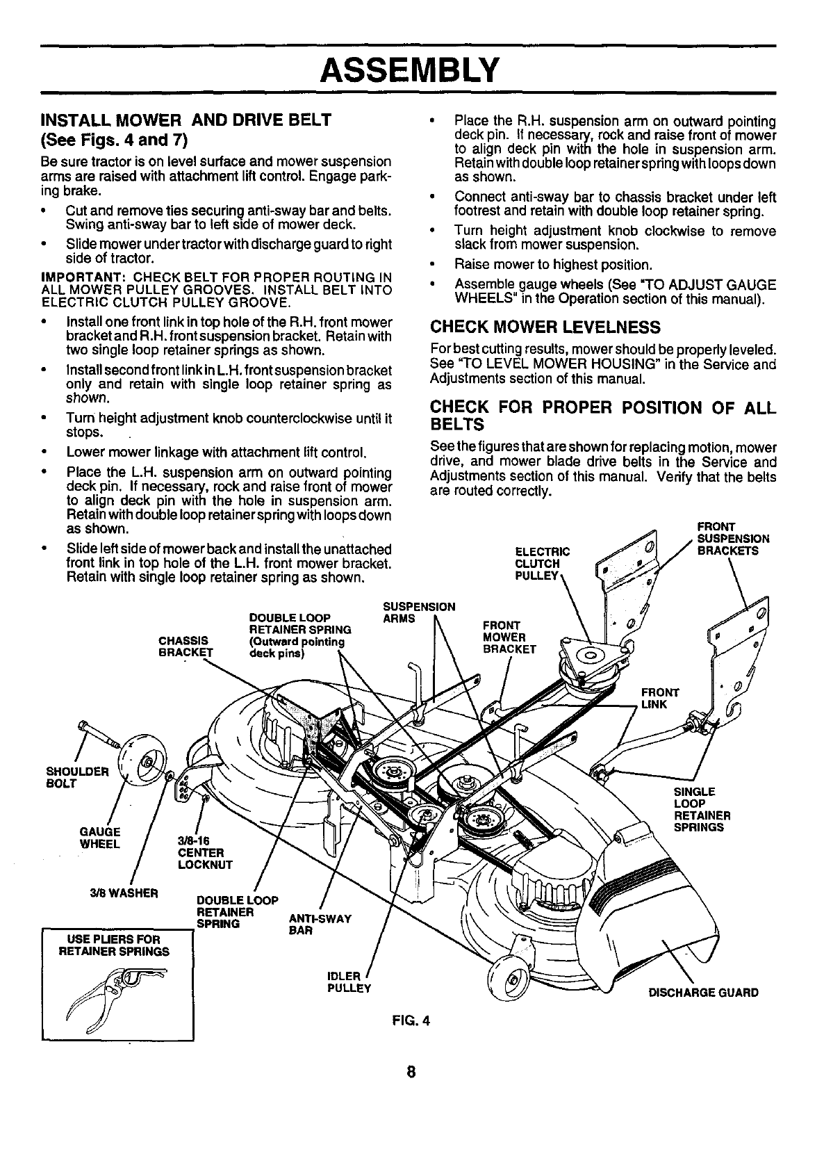
INSTALL MOWER AND DRIVE BELT
(See Figs. 4 and 7)
Be sure tractor is on level surface and mower suspension
arms are raised with attachment liftcontrol, Engage park-
ing brake.
•Cut and remove ties securing anti-sway bar and belts.
Swing anti-sway barto left side of mower deck.
•Slide mower under tractor with discharge guard to right
side of tractor.
IMPORTANT: CHECK BELT FOR PROPER ROUTING IN
ALL MOWER PULLEY GROOVES. INSTALL BELT INTO
ELECTRIC CLUTCH PULLEY GROOVE.
Install one front link in top hole of the R.H. front mower
bracket and R.H. front suspension bracket. Retain with
two single loop retainer springs as shown.
Install second front linkinL.H. front suspension bracket
only and retain with single loop retainer spring as
shown.
• Turn height adjustment knob counterclockwise until it
stops.
• Lower mower linkage with attachment lift control.
• Place the L.H. suspension arm on outward pointing
deck pin. If necessary, rock and raise front of mower
to align deck pin with the hole in suspension arm.
Retain with double loop retainer springwith loops down
as shown.
•Slide left side of mower back and installthe unattached
front link in top hole of the L.H. front mower bracket.
Retain with single loop retainer spring as shown,
DOUBLE LOOP
RETAINER SPRING
CHASSIS (Outward pointing
BRACKET deck pins)
SUSPENSION
ARMS
Place the R.H. suspension arm on outward pointing
deck pin. If necessary, rock and raise front of mower
to align deck pin with the hole in suspension arm.
Retain with double loop retainer spring with loops down
as shown.
• Connect anti-sway bar to chassis bracket under left
footrest and retain with double loop retainer spring.
• Turn height adjustment knob clockwise to remove
slack from mower suspension.
Raise mower to highest position.
•Assemble gauge wheels (See "TO ADJUST GAUGE
WHEELS" in the Operation section of this manual).
CHECK MOWER LEVELNESS
For best cutting results, mower should be properly leveled.
See "TO LEVEL MOWER HOUSING" in the Service and
Adjustments section of this manual.
CHECK FOR PROPER POSITION OF ALL
BELTS
See the figures that are shown for replacing motion, mower
drive, and mower blade drive belts in the Service and
Adjustments section of this manual. Vedfy that the belts
are routed correctly.
ELECTRIC
CLUTCH
PULLEY
FRONT
SUSPENSION
BRACKETS
FRONT
MOWER
BRACKET
SHOULDER
BOLT
GAUGE
WHEEL
3/SWASHER
USE PUERS FOR
RETAINER SPRINGS
3/8-16
CENTER
LOCKNUT
DOUBLE LOOP
RETAINER
SPRING ANTI-SWAY
BAR
IDLER
PULLEY
FIG. 4
SINGLE
LOOP
RETAINER
SPRINGS
DISCHARGE GUARD
8
ASSEMBLY
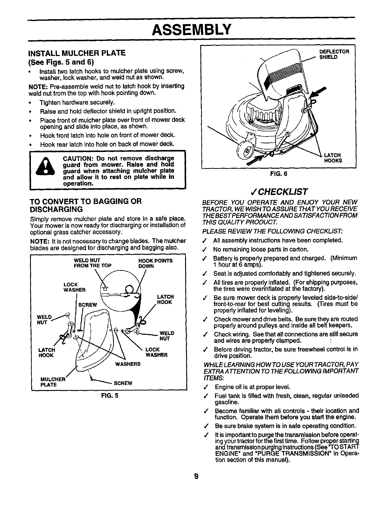
INSTALL MULCHER PLATE
(See Figs. 5 and 6)
• Install two latch hooks to mulcher plate using screw,
washer, lock washer, and weld nut as shown.
NOTE: Pre-assemble weld nut to latch hook by inserting
weld nut from the top with hook pointing down.
•Tighten hardware securely.
•Raise and hold deflector shield in upright position.
•Place front of mulcher plate over front of mower deck
opening and slide into place, as shown.
•Hook front latch into hole on front of mower deck.
•Hook rear latch into hole on back of mower deck.
CAUTION: Do not remove discharge
guard from mower. Raise and hold
guard when attaching mulcher plate
and allow it to rest on plate while in
operation.
TO CONVERT TO BAGGING OR
DISCHARGING
Simply remove mulcher plate and store in a safe place.
Your mower is now ready for discharging or installation of
optional grass catcher accessory.
NOTE: It is not necessary to change blades. The mulcher
blades are designed for discharging and bagging also.
WELD NUT HOOK POtNTS
FROM THE TOP DOWN
LOCK
WASHER
LATCH
HOOK
WELD
NUT
LATCH LOCK
HOOK WASHER
WASHERS
MULCHER
PLATE SCREW
FIG. 5
DEFLECTOR
SHIELD
LATCH
HOOKS
FIG. 6
,/CHECKLIST
BEFORE YOU OPERATE AND ENJOY YOUR NEW
TRACTOR, WE WISH TO ASSURE THAT YOU RECEIVE
THE BEST PERFORMANCE AND SA TISFA CTION FROM
THIS QUALITY PRODUCT.
PLEASE REVIEW THE FOLLOWING CHECKLIST:
/All assembly instructions have been completed.
/No remaining loose parts in carton.
,/ Battery is properly prepared and charged. (Minimum
1 hour at 6 amps).
/Seat is adjusted comfortably and tightened securely.
,/ All tires are properly inflated. (For shipping purposes,
the tires were ovednflated at the factory).
/Be sure mower deck is propedy leveled side-to-side/
frent-to-rear for best cutting results. (Tires must be
properly inflated for leveling),
/Check mower and drive belts. Be sure they are routed
properly around pulleys and inside all belt keepers.
/Check wiring. See that all connections are still secure
and wires are propedy clamped.
/Before driving tractor, be sure freewheel control is in
drive position.
WHILE LEARNING HOW TO USE YOUR TRACTOR, PAY
EXTRA A TTENTION TO THE FOLLOWING IMPORTANT
ITEMS:
•/ Engine oil is at proper level.
/ Fuel tank is filled with fresh, clean, regular unleaded
gasoline.
/Become familiar with all controls - their location and
function. Operate them before you start the engine.
,/ Be sure brake system is in safe operating condition.
/It is importantto purge the transmission before operat-
ingyourtractor forthe firsttime. Follow proper starting
and transmission purging instructions(See "TOSTART
ENGINE" and "PURGE TRANSMISSION" in Opera-
tion section of this manual),
9
OPERATION
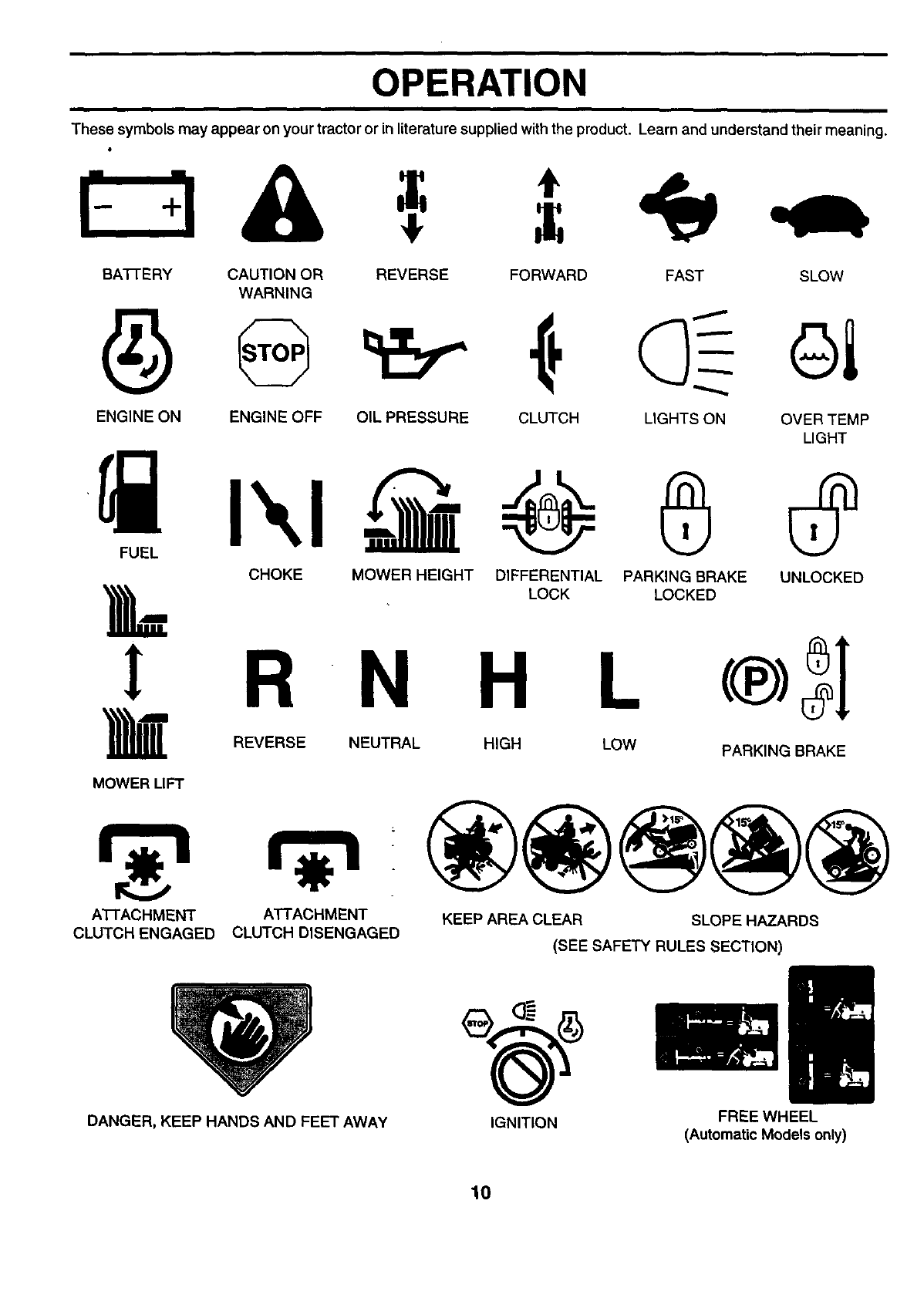
These symbols may appear on your tractor or in literature supplied with the product. Learn and understand their meaning.
=,
BAFIERY CAUTION OR REVERSE FORWARD
WARNING
FAST SLOW
ENGINE ON ENGINE OFF OIL PRESSURE CLUTCH LIGHTS ON OVER TEMP
LIGHT
CHOKE MOWER HEIGHT DIFFERENTIAL PARKING BRAKE UNLOCKED
LOCK LOCKED
I R N H L
REVERSE NEUTRAL HIGH LOW PARKING BRAKE
MOWER LIFT
A'I-rACHMENT
CLUTCH ENGAGED
ATTACHMENT
CLUTCH DISENGAGED KEEP AREA CLEAR SLOPE HAZARDS
(SEE SAFETY RULES SECTION)
DANGER, KEEP HANDS AND FEET AWAY IGNITION FREE WHEEL
(Automatic Models only)
10
OPERATION
i
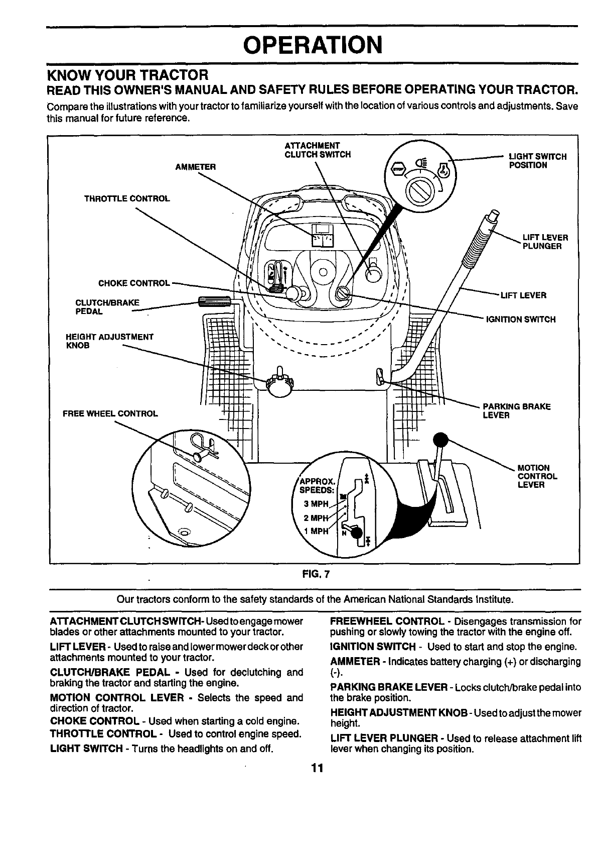
KNOW YOUR TRACTOR
READ THIS OWNER'S MANUAL AND SAFETY RULES BEFORE OPERATING YOUR TRACTOR.
Compare the illustrationswith your tractor to familiarize yourself withthe location of various controls and adjustments. Save
this manual for future reference,
ATTACHMENT
CLUTCH SWITCH LIGHT SWITCH
AMMETER POSITION
THROTTLE CONTROL
LIFT LEVER
LIFT LEVER
CLUTCH/BRAKE
PEDAL IGNITION SWITCH
HEIGHT ADJUSTMENT
KNOB
FREE WHEEL CONTROL PARKING BRAKE
LEVER
APPRO_
SPEEDS:
MOTION
CONTROL
LEVER
FIG. 7
Our tractors conform to the safety standards of the Amedcan National Standards Institute.
AI"rACHMENT CLUTCH SWITCH- Usedto engage mower
blades or other attachments mounted to your tractor.
LIFT LEVER -Used to raise and lower mower deck orother
attachments mounted to your tractor.
CLUTCH/BRAKE PEDAL -Used for declutching and
braking the tractor and starting the engine.
MOTION CONTROL LEVER -Selects the speed and
direction of tractor.
CHOKE CONTROL - Used when starting a cold engine.
THROTTLE CONTROL - Used to control engine speed.
LIGHT SWITCH - Turns the headlights on and off.
FREEWHEEL CONTROL - Disengages transmission for
pushing or slowly towing the tractor with the engine off.
IGNITION SWITCH - Used to start and stop the engine.
AMMETER - Indicates battery charging (+) or discharging
(-).
PARKING BRAKE LEVER - Locks clutch/brake pedal into
the brake position.
HEIGHT ADJUSTMENT KNOB- Used to adjustthe mower
height.
LIFT LEVER PLUNGER - Used to release attachment lift
lever when changing its position.
11
OPERATION
I
The operation of any tractor can result in foreign objects thrown into the eyes, which can result |
in severe eye damage. Always wear safety glasses or eye shields while operating your tractor I
or performing any adjustments or repairs. We recommend a wide vision safety mask over
spectacles or standard safety glasses.
HOW TO USE YOUR TRACTOR
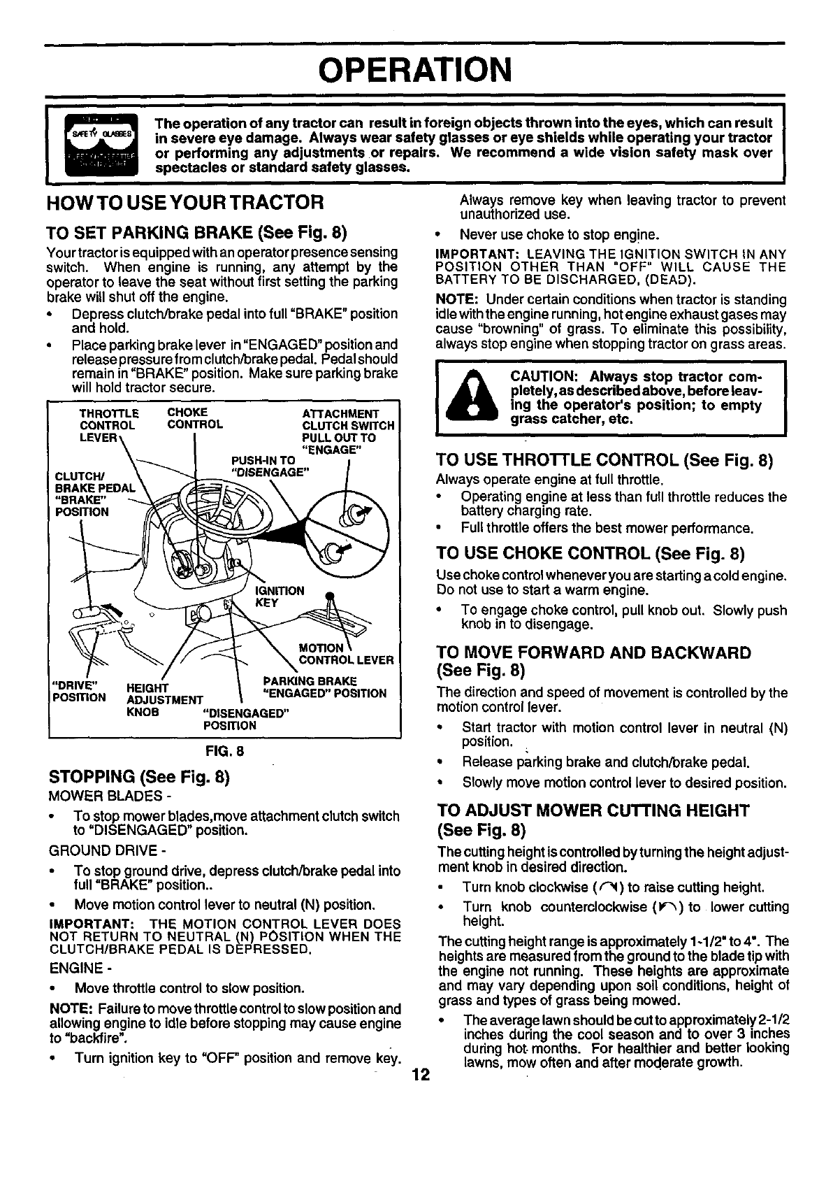
TO SET PARKING BRAKE (See Fig. 8)
Your tractor isequipped with an operator presence sensing
switch. When engine is running, any attempt by the
operator to leave the seat without first setting the parking
brake will shut off the engine.
•Depress clutch/brake pedal into full "BRAKE" position
and hold.
•Place parking brake lever in"ENGAGED" position and
release pressure from clutch/brake pedal. Pedal should
remain in "BRAKE" position. Make sure parking brake
will hold tractor secure.
THROTTLE CHOKE
CONTROL CONTROL
CLUTCH/
BRAKE PEDAL
"BRAKE"
PosmoN
ATTACHMENT
CLUTCH SWITCH
PULL OUTTO
"ENGAGE"
PUSH-INTO
"DISENGAGE"
MORON
CONTROLLEVER
PARING BRAKE
"DRIVE" HEIGHT "ENGAGED"POSITION
PosmoN ADJUSTMENT
KNOB "DISENGAGED"
POSITION
FIG. 8
STOPPING (See Fig. 8)
MOWER BLADES -
To stop mower blades,move attachment clutch switch
to =DISENGAGED position.
GROUND DRIVE -
•To stop ground drive, depress clutch/brake pedal into
full =BRAKE" position..
•Move motion control lever to neutral (N) position.
IMPORTANT: THE MOTION CONTROL LEVER DOES
NOT RETURN TO NEUTRAL (N) POSITION WHEN THE
CLUTCH/BRAKE PEDAL IS DEPRESSED.
ENGINE -
•Move throttle control to slow position.
NOTE: Failure to move throttle controlto slowpositionand
allowing engine to idle before stopping may cause engine
to "backfire".
• Turn ignition key to =OFF" position and remove key. 12
Always remove key when leaving tractor to prevent
unauthorized use.
•Never use choke to stop eng!ne.
IMPORTANT: LEAVING THE IGNITION SWITCH IN ANY
POSITION OTHER THAN "OFF" WILL CAUSE THE
BATTERY TO BE DISCHARGED. (DEAD).
NOTE: Under certain conditions when tractor is standing
idle with the engine running, hot engine exhaust gases may
cause "browning" of grass. To eliminate this possibility,
always stop engine when stopping tractor on grass areas.
pletely, as described above, before leav-
ing the operator's position; to empty
grass catcher, etc.
TO USE THROTrLE CONTROL (See Fig. 8)
Always operate engine at full throttle.
Operating engine at less than full throttle reduces the
battery charging rate.
• Full throttle offers the best mower performance.
TO USE CHOKE CONTROL (See Fig. 8)
Use choke controlwhenever you are startinga cold engine.
Do not use to start a warm engine.
•To engage choke control, pull knob out. Slowly push
knob in to disengage.
TO MOVE FORWARD AND BACKWARD
(See Fig. 8)
The direction and speed of movement is controlled by the
motion control lever,
° Start tractor with motion control lever in neutral (N)
position.
•Release parking brake and clutch/brake pedal,
•Slowly move motion control lever to desired position,
TO ADJUST MOWER CUTTING HEIGHT
(See Fig. 8)
The cuttingheight is controlled by turningthe heightadjust-
ment knob in desired direction.
Turn knob clockwise (/'_) to raise cutting height.
•Turn knob counterclockwise (P'_) to lower cutting
height.
The cuttingheight range is approximately 1-1/2" to 4". The
heights are measured from the ground to the blade tip with
the engine not running. These heights are approximate
and may vary depending upon soil conditions, height of
grass and types of grass being mowed.
•The average lawn should be cut to approximately 2-1/2
inches during the cool season and to over 3 inches
during hot. months. For healthier and better looking
lawns, mow often and after moderate growth.
OPERATION
For best cuttingperformance grass over 6 inches in
height should be mowed twice. Make the f rst cut
relatively high; the second to desired height.
TO ADJUST GAUGE WHEELS (See Fig. 9)
Gauge wheels are properly adjusted when they are slightly
off the ground when mower is at the desired cuttingheight
in operating position. Gauge wheels then keep the deck in
proper position to help prevent scalping in most terrain
conditions.
Adjust gauge wheels with tractor on a flat level surface.
Ad ust mower to desired cutting height (See "TO AD-
JUST MOWER CUTT NG HE GHT" n the Operat on
section of this manual).
With mower in desired height of cut position, gauge
wheels should be assembled so they are slightly off the
ground. Install gauge wheel in appropriate hole with
shoulder bolt, 3/8 washer, and 3/8-16 Iocknut and
tighten securely.
Repeat for opposite side installing gauge wheel in
same adjustment hole.
GUAGE
WHEEL
MOUN_NG
BRACKET
F!G. 9
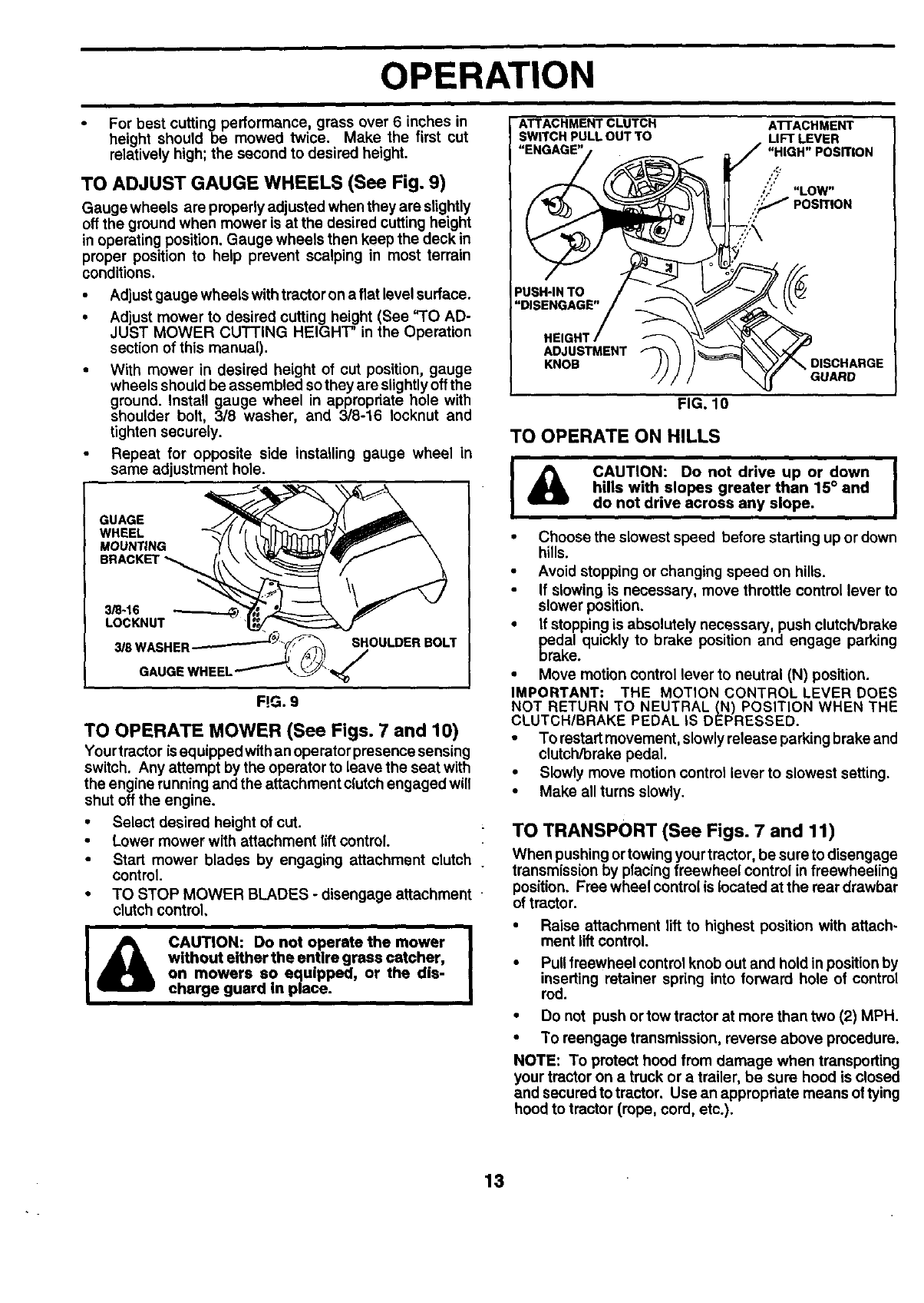
TO OPERATE MOWER (See Figs. 7 and 10)
Your trector isequipped withan operator presence sensing
switch. Any attempt by the operator to leave the seat with
the engine running and the attachment clutch engaged will
shut off the engine.
• Select desired height of cut.
•Lower mower with attachment lift control.
•Start mower blades by engaging attachment clutch .
control.
•TO STOP MOWER BLADES -disengage attachment
clutch control,
I& CAUTION: Do not operate the mower I
|
without either the entire grass catcher, I
on mowers so equipped, or the dis-
charge guard In place.
ATTACHMENT CLUTCH ATI'ACHMENT
SWITCH PULL OUT TO LIFT LEVER
"ENGAGE"/ -/"HIGH" POSFrlON
o @
!iN osc.,.o,
GUARD
FIG. 10
TO OPERATE ON HILLS
I _ CAUTION: Do not drive up or down
dBk hills with slopes greater than 15° and
do not drive across any slope.
• Choose the slowest speed before starting up or down
hills.
• Avoid stopping or changing speed on hills.
If slowing is necessary, move throttle control lever to
slower position.
• If stopping is absolutely necessary, push clutch/brake
_edal quickly to brake position and engage parking
rake.
•Move motion control lever to neutral (N) position.
IMPORTANT: THE MOTION CONTROL LEVER DOES
NOT RETURN TO NEUTRAL (N) POSITION WHEN THE
CLUTCH/BRAKE PEDAL IS DEPRESSED.
•To restart movement, slowly release parking brake and
clutch/brake pedal.
•Slowly move motion control lever to slowest setting.
•Make all turns slowly.
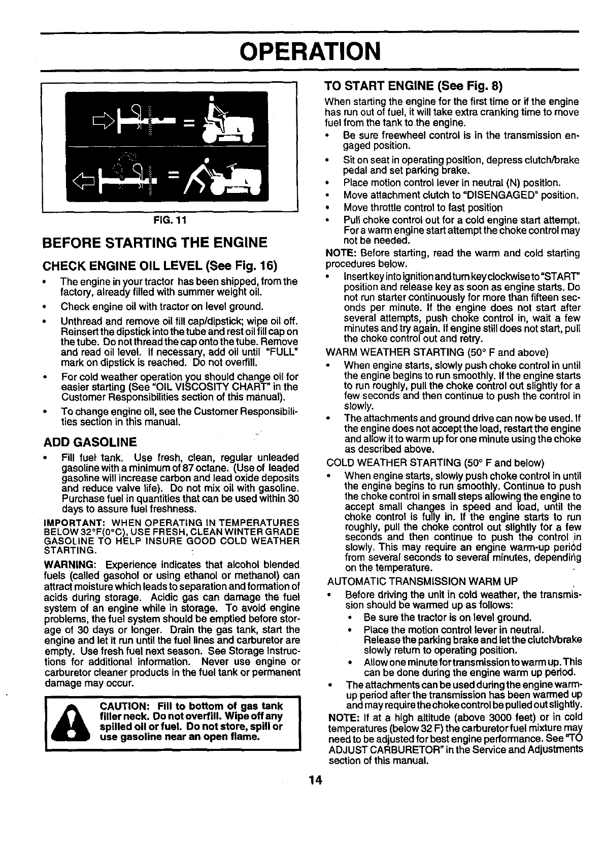
TO TRANSPORT (See Figs. 7 and 11)
When pushing ortowing your tractor, be sure to disengage
transmiss(on by placing freewheel control in freewheeling
position. Free wheel control is located at the rear drawbar
of tractor.
•Raise attachment lift to highest position with attach-
ment liftcontrol.
• Pull freewheel control knob out and hold in position by
inserting retainer spring into forward hole of control
rod.
•Do not push ortow tractor at more than two (2) MPH.
•To reengage transmission, reverse above procedure.
NOTE: To protect hood from damage when transporting
your tractor on a truck or a trailer, be sure hood is closed
and secured to tractor, Use an appropriate means of tying
hood to tractor (rope, cord, etc.).
13
OPERATION
FIG. 11
BEFORE STARTING THE ENGINE
CHECK ENGINE OIL LEVEL (See Fig. 16)
• The engine inyour tractor has been shipped, fromthe
factory, already filled with summer weight oil.
• Check engine oil With tractor on level ground.
• Unthread and remove oil fill cap/dipstick; wipe oil off.
Reinsert the dipstick into the tube and rest oil fill cap on
the tube. Do not thread the cap onto the tube. Remove
and read oil level. If necessary, add oil until =FULL"
mark on dipstick is reached. Do not overfill.
• For cold weather operation you should change oil for
easier starting (See =OIL VISCOSITY CHART" in the
Customer Responsibilities section of this manual).
• To change engine oil, see the Customer Responsibili-
ties section in this manual.
ADD GASOLINE
•Fill fuel tank. Use fresh, clean, regular unleaded
gasoline with a minimum of 87 octane. (Use of leaded
gasoline will increase carbon and lead oxide deposits
and reduce valve life). Do not mix oil with gasoline.
Purchase fuel in quantities that can be used within 30
days to assure fuel freshness.
IMPORTANT: WHEN OPERATING IN TEMPERATURES
BELOW 32°F(0°C), USE FRESH, CLEAN WINTER GRADE
GASOLINE TO HELP INSURE GOOD COLD WEATHER
STARTING.
WARNING: Experience indicates that alcohol blended
fuels (called gasohol or using ethanol or methanol) can
attract moisture which leads to separation and formation of
acids during storage. Acidic gas can damage the fuel
system of an engine while in storage. To avoid engine
problems, the fuel system should be emptied before stor-
age of 30 days or longer. Drain the gas tank, start the
engine and let it run until the fuel lines and carburetor are
empty. Use fresh fuel next season. See Storage Instruc-
tions for additional information. Never use engine or
carburetor cleaner products in the fuel tank or permanent
damage may occur.
I& AUTION: Fill to bottom of gas tank
filler neck. Do not overfill. Wipe off any
spilled oil or fuel. Do not store, spill or
use gasoline near an open flame.
TO START ENGINE (See Fig. 8)
When starting the engine for the first time or if the engine
has run out of fuel, it will take extra cranking time to move
fuel from the tank to the engine.
Be sure freewheel control is in the transmission en-
gaged position.
•Sit on seat in operating position, depress clutch/brake
pedal and set parking brake.
•Place motion control lever in neutral (N) position.
Move attachment clutch to "DISENGAGED" position.
•Move throttle control to fast position
•Pull choke control out for a cold engine start attempt.
For a warm engine start attempt the choke control may
not be needed.
NOTE: Before starting, read the warm and cold starting
procedures below.
• Insert key intoignition and turn keyclockwise to "START"
position and release key as soon as engine starts. Do
not run starter continuously for more than fifteen sec-
onds per minute. If the engine does not start after
several attempts, push choke control in, wait a few
minutes and try again. If engine still does not start, pull
the choke control out and retry.
WARM WEATHER STARTING (50 °F and above)
• When engine starts, slowly push choke control in until
the engine begins to run smoothly. If the engine starts
to run roughly, pullthe choke control out slightly for a
few seconds and then continue to push the control in
slowly.
• The attachments and ground drive can now be used. If
the engine does not accept the load, restart the engine
and allow it to warm up for one minute using the choke
as described above.
COLD WEATHER STARTING (50° F and below)
•When engine starts, slowly push choke control in until
the engine begins to run smoothly. Continue to push
the choke control insmall steps allowing the engine to
accept small changes in speed and load, until the
choke control is fully in. If the engine starts to run
roughly, pull the choke control out slightly for a few
seconds and then continue to push the control in
slowly. This may require an engine warm-up period
from several seconds to several minutes, dependir_g
on the temperature.
AUTOMATIC TRANSMISSION WARM UP
•Before driving the unit in cold weather, the transmis-
sion should be warmed up as follows:
•Be sure the tractor is on level ground.
•Place the motion control lever in neutral.
Release the parking brake and let the clutch/brake
slowly return to operating position.
•Allowone minute for transmission to warm up. This
can be done during the engine warm up period.
• The attachments can be used duringthe engine warm-
up period after the transmission has been warmed up
and may requira the choke control be pulled out slightly.
NOTE: If at a high altitude (above 3000 feet) or in cold
temperatures (below 32 F) the carburetor fuel mixture may
need to be adjusted for best engine performance. See "TO
ADJUST CARBURETOR" in the Service and Adjustments
section of this manual.
14
OPERATION
PURGE TRANSMISSION •
I_CAUTION:Neverengageordisengage I
freewheel lever while the engine is run-
ning.
To ensure proper operation and performance, it is recom-
mended that the transmission be purged before operating
tractor for the first time. This procedure will remove any
trapped air inside the transmission which may have devel-
oped during shipping of your tractor.
IMPORTANT: SHOULD YOU R TRANSMISSION REQUIRE
REMOVAL FOR SERVICE OR REPLACEMENT, IT
SHOULD BE PURGED AFTER REINSTALLATION
BEFORE OPERATING THE TRACTOR.
•Place tractor safely on level surface withengine off and
parking brake set.
6 Disengage transmission by placing freewheel control
in freewheeling position (See "TO TRANSPORT" in
this section of manual).
• Sitting in the tractor seat, start engine. After the engine
is running, move throttle control to slow position. With
motion control lever in neutral (N) position, slowly
disengage clutch/brake pedal.
• Move motion control lever to full forward position and
hold for five (5) seconds. Move lever to full reverse
position and hold for five (5) seconds. Repeat this
procedul'e three (3) times.
NOTE; During this procedure there will be no movement of
drive wheels. The air is being removed from hydraulic drive
system.
• Move motioncontrolleverto neutral(N) position. Shut-
off engine and set parking brake,
•Engage transmission by placing freewheel control in
driving position (See "TO TRANSPORT" in this section
of manual).
• Sitting inthetractor seat, start engine. Afterthe engine
is running, move throttle control to half (1/2) speed.
With motion control lever in neutral (N) position, slowly
disengage clutch/brake pedal.
• Slowly move motion control lever forward, after the
tractor moves approximately five (5) feet, slowly move
motion control lever to reverse position. After the
tractor moves approximately five (5) feet return the
motion control lever tothe neutral (N) position, Repeat
this procedure with the motion control lever three (3)
times.
•Your tractor is now purged and now ready for normal
operation.
MOWlNGTIPS
Tire chains cannot be used when the mower housing is
attached to tractor.
• Mower should be properly leveled for best mowing
performance. See "TO LEVEL MOWER HOUSING in
the Service and Adjustments section of this manual.
• The left hand side of mower should be used for.trim-
ming.
,, Drive so that clippings are discharged onto the area
that has been cut. Have the cut area to the right of the
tractor. This will result in a more even distribution of
clippings and more uniform cutting.
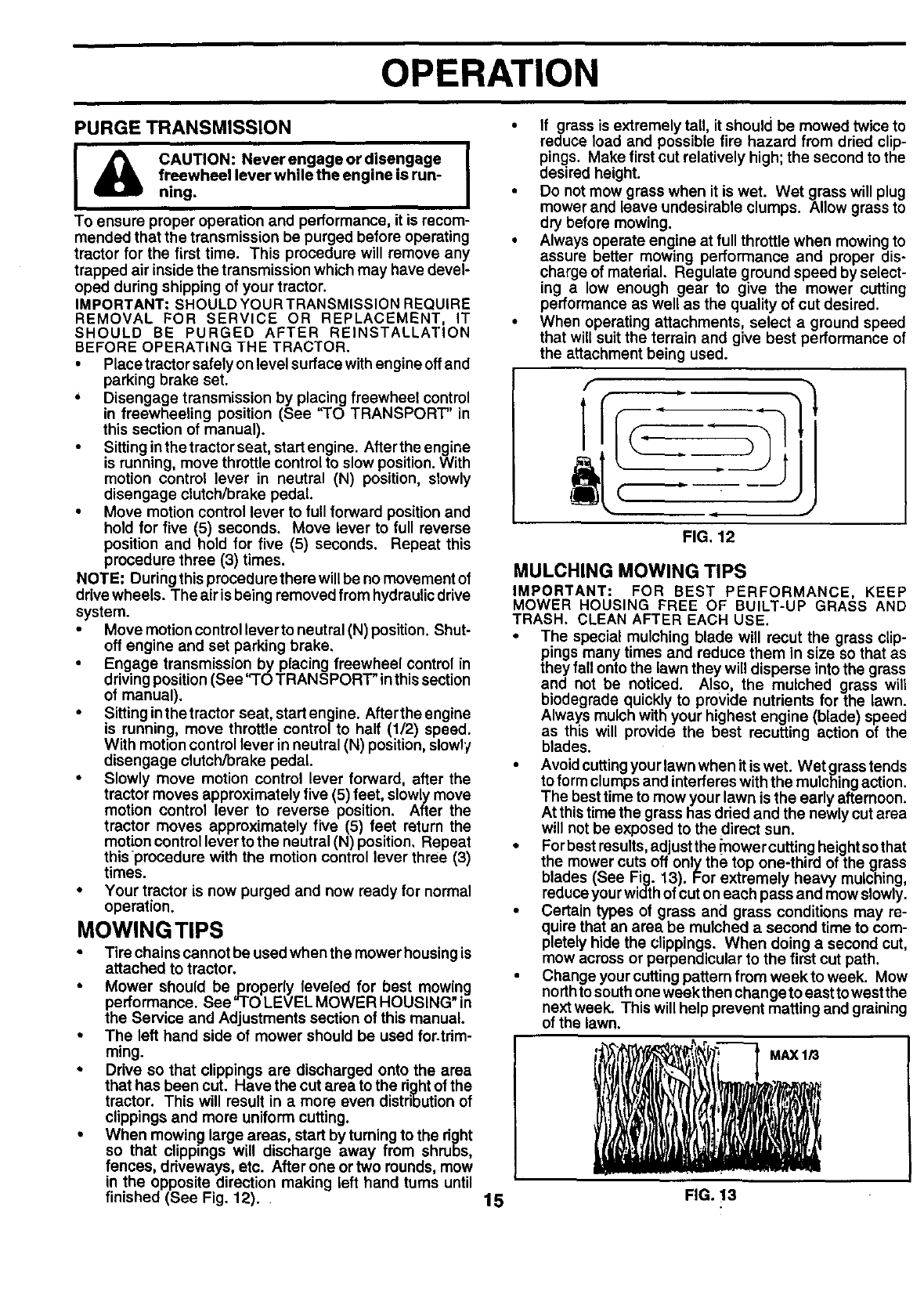
• When mowing large areas, start by turning to the right
so that clippings will discharge away from shrubs,
fences, driveways, etc. After one or two rounds, mow
in the opposite direction making left hand turns until
finished (See Fig. 12).
If grass is extremely tall, it should be mowed twice to
reduce load and possible fire hazard from dried clip-
pings. Make first cut relatively high; the second to the
desired height.
•Do not mow grass when it is wet. Wet grass will plug
mower and leave undesirable clumps. Allow grass to
dry before mowing.
•Always operate engine at full throttle when mowing to
assure better mowing performance and proper dis-
charge of material. Regulate ground speed by select-
ing a low enough gear to give the mower cutting
performance as well as the quality of cut desired.
•When operating attachments, select a ground speed
that will suit the terrain and give best performance of
the attachment being used.
f
FIG. 12
MULCHING MOWING TIPS
IMPORTANT: FOR BEST PERFORMANCE, KEEP
MOWER HOUSING FREE OF BUILT-UP GRASS AND
TRASH. CLEAN AFTER EACH USE.
The special mulching blade will recut the grass clip-
pings many times and reduce them in size so that as
they fall onto the lawn they will disperse into the grass
and not be noticed. Also, the mulched grass will
biodegrade quickly to provide nutrients for the lawn.
Always mulch with your highest engine (blade) speed
as this will provide the best recutting action of the
blades.
Avoidcuttingyour lawn when it is wet. Wet grass tends
to form clumps and interferes with the mulching action.
The best time to mow your lawn is the early afternoon.
At thistime the grass has dried and the newly cut area
will not be exposed to the direct sun.
For best results,adjust the _'nowercutting heightso that
the mower cuts off only the top one-third of the grass
blades (See Fig. 13). For extremely heavy mulching,
reduce your width of cut on each pass and mow slowly.
Certain types of grass and grass conditions may re-
quire that an area be mulched a second time to com-
pletely hide the clippings. When doing asecond cut,
mow across or perpendicular to the first cut path.
Change your cuttingpattern frem week to week. Mow
northto south one week then change to east towest the
next week. This will help prevent matting and graining
of the lawn.
'! i "
15 FIG. 13
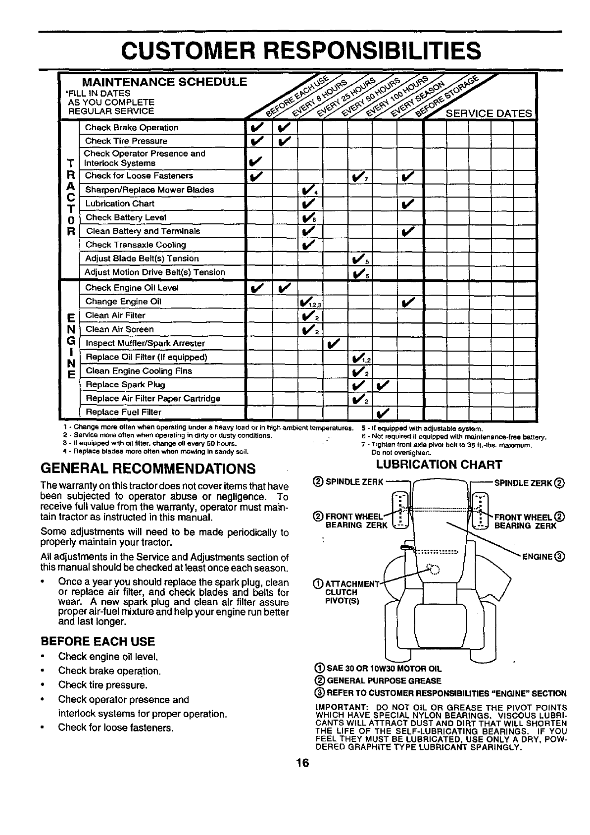
CUSTOMER RESPONSIBILITIES
• MAINTENANCE SCHEDULE
FILL,.OASES "
ASYOUCOMP ETE O,-
Check Brake Operation _V'
Check Tire Pressure
Check Operator Presence and
T Interlock Systems
Check for Loose Fasteners V'_ V °
A Sharpen/Replace Mower Blades _V_s4
Lubrication Chart !l/
TCheck Battery Level
RClean Battery and Terminals V_
Check Transaxle Cooling
Adjust Blade Belt(s) Tension V's
Adjust Motion Drive Belt(s) Tension V_s
Check Engine Oil Level I_ if
Change Engine Oil _,3 if
EC!ean Air Filter ll_:_
NClean Air Screen I_'_
Inspect Muffler/SparkArrester If
Replace Oil Filter (If equipped) ._jl.2
NClean Engine Cooling Fins lit2
Replace Spark Plug V /
Replace Air Filter Paper Cartridge
Replace Fuel Filter
1-Change more often when operating under a heavy toad or in high ambient temperatures. 5 oIf equipped With adjustable system.
;_ - Service more often when operating in dirty or dusty conditions. .6-Not requirecl if equipped with maintenance-free battery.
3 - If equipped with oil filter, change oil every 50 hours.
4 - Replace blades more often when moWing in sandy soil.
GENERAL RECOMMENDATIONS
The warranty on thistractor does not cover items that have
been subjected to operator abuse or negligence. To
receive full value from the warranty, operator must main-
tain tractor as instructed in this manual.
Some adjustments will need to be made periodically to
properly maintain your tractor.
All adjustments in the Service and Adjustments section of
this manual should be checked at least once each season.
Once a year you should replace the spark plug, clean
or replace air filter, and check blades and belts for
wear. A new spark plug and clean air filter assure
proper air-fuel mixture and help your engine run better
and last longer.
BEFORE EACH USE
Check engine oil level,
Check brake operation.
• Check tire pressure.
•Check operator presence and
interlock systems for proper operation.
Check for loose fasteners.
7 - Tightenfrontaxle pivotboltto 35 ft.*lbs, maximum,
DOnotovertighten,
LUBRICATION CHART
®A AC.MENT-(l
CLUTCH
PIVOT(B)
®SAE 30 OR 10W3_OTOR OIL
®GENERAL PURPOSE GREASE
SPINDLE ZERK®
P0 o , WBz :
_ _ENGINE®
(_ REFER TO CUSTOMER RESPONSIBILITIES "ENGINE" SECTION
IMPORTANT: DO NOT OiL OR GREASE THE PIVOT POINTS
WHICH HAVE SPECIAL NYLON BEARINGS. VISCOUS LUBRI-
CANTS WILL ATTRACT DUST AND DIRT THAT WILL SHORTEN
THE LIFE OF THE SELF-LUBRICATING BEARINGS. IF YOU
FEEL THEY MUST BE LUBRICATED, USE ONLY A DRY, POW-
DERED GRAPHITE TYPE LUBRICANT SPARINGLY.
16
CUSTOMER RESPONSIBILITIES
TRACTOR
Alwaysobservesafetyruleswhenperformingany maintenance.
BRAKE OPERATION
Iftractorrequiresmore thansix(6)feat stoppingdistance at high
speed in highest gear, then brake must be adjusted. (See "TO
ADJUST BRAKE"inthe Service and Adjustments sectionof this
manual).
TIRES
•Maintain proper air pressure inall tires (See =PRODUCT
SPECIFICATIONS" on page 3 of this manual).
•Keep tires free of gasoline, oil, or insect control chemicals
which can harm rubber.
•Avoidstumps, stones,deep ruts, sharpobjects and other
hazards that may cause tire damage.
NOTE: To seal tire punctures and prevent flat tires due to slow
leaks, tiresealant may bepurchased from your localpartsdealer.
Tire sealant also prevents tire dry rot and corrosion.
OPERATOR PRESENCESYSTEM
Be sure operatorpresenceand interlecksystemsare work_'_j
properly. Ifyourtractordoes notfunction asdescribed, repairthe
problemimmediately.
•The engineshouldnot startunlesstheclutch/brakepedal is
fully depressed and attachementclutch controlis in the
disengagedposition.
•When the engineis running,any attemptbythe operatorto
leave the seatwithoutfirst setting the pe_ng brake should
shutoffthe engine.
When the engine is running and the attachmentclutch is
engaged, any attempt by the operatorto leave the seat
shouldshutoffthe engine.
The attachment clutch should never operate unless the
operator is in the seat.
BLADE CARE
Forbestresultsmowerblades mustbe keptsharp.Replacebent
or damaged blades.
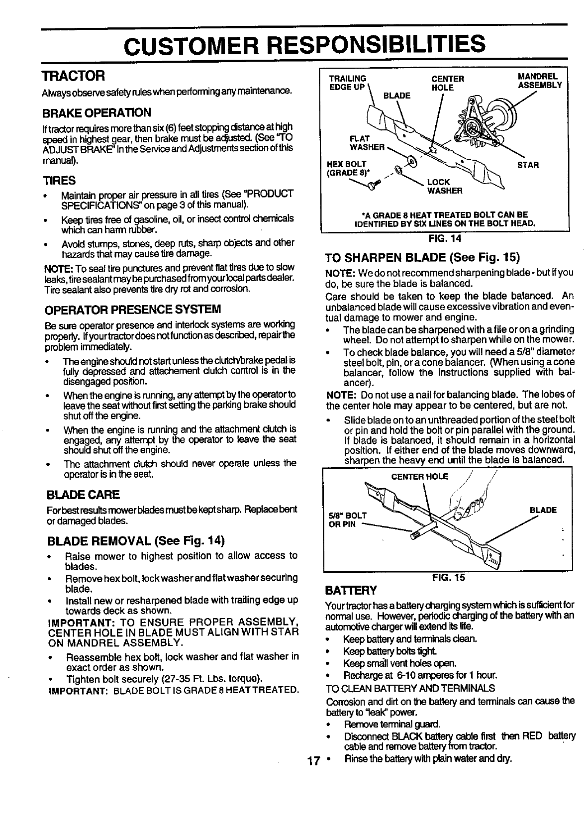
BLADE REMOVAL (See Fig. 14)
•Raise mower to highest position to allow access to
blades.
•Remove hex bolt, leck washer and flat washer secudng
blade.
• Install new or resharpened blade with trailing edge up
towards deck as shown.
IMPORTANT; TO ENSURE PROPER ASSEMBLY,
CENTER HOLE IN BLADE MUST ALIGN WITH STAR
ON MANDREL ASSEMBLY.
• Reassemble hex bolt, lock washer and flat washer in
exact order as shown.
Tighten bolt securely (27-35 Ft. Lbs. torque).
IMPORTANT: BLADE BOLT IS GRADE 8 HEAT TREATED.
TRAILING CENTER
EDGE UP HOLE
BLADE
MANDREL
ASSEMBLY
FLAT
WASHER
HEX BOLT / "
(GRADE 8)* "_ LOCK
WASHER
STAR
"A GRADE 8 HEAT TREATED BOLT CAN BE
IDENTIFIED BY SiX UNEB ON THE BOLT HEAD.
FIG. 14
TO SHARPEN BLADE (See Fig. 15)
NOTE: We do notrecommend sharpening blade- but ifyou
do, be sure the blade is balanced.
Care should be taken to keep the blade balanced. An
unbalanced blade will cause excessive vibration and even-
tual damage to mower and engine.
•The blade can be sharpened with a fileor on agdnding
wheel. Do not attempt to sharpen while on the mower.
•To check blade balance, you will need a 5/8" diameter
steel bolt, pin, or acone balancer. (When usingacone
balancer, follow the instructions supplied with bal-
ancer).
NOTE: Do not use anail for balancing blade. The lobes of
the center hole may appear to be centered, but are not.
• Slide blade on to an unthreaded portion of the steel bolt
or pin and hold the bolt or pin parallel with the ground.
If blade is balanced, it should remain in a horizontal
position. If either end of the blade moves downward,
sharpen the heavy end until the blade is balanced.
-CENTER HOLE / j
FIG. 15
BATrERY
Yourtractor has abattery chargingsystemwhichissuff_ent for
normal use. However,periodicchargingof the batterywithan
automotivechargerwillextenditslife.
• Keep battery and terminalsdean.
•Keepbatteryho_stight.
• Keep srr_l vent holes open.
•Rechargeat 6-10 amperes for 1 hour.
TO CLEAN BATIERY AND TERMINALS
Corrosionand dirt on the battery and terminals can cause the
bettery to "leak" power.
• Remove terminalguard.
•DisconnectBLACK batterycable first then RED battery
cableand removebattery fromtractor.
17 * Rinse the batterywifhplainwater and dry.
CUSTOMER RESPONSIBILITIES
•Cleanterminalsand batterycableendswithwirebrush until TO CHANGE ENGINE OIL (See Fig. 16)
bright.
Coat terminals with grease or petroleum jelly.
Reinstall battery (See "CONNECT BATTERY" in the As-
sembly section of this manual).
TRANSAXLE COOLING
The fan and cooling fins of transmission should be kept
clean to assure proper cooling.
Do notattempt to clean fan ortransmission while engine is
running or while the transmission is hot. To prevent
possible damage to seals, no not use high pressure water
or steam to clean transaxle.
•Inspect coolingfan to be sure fan blades are intactand
clean.
•Inspect cooling fins for dirt, grass clippings and other
materials. To prevent damage to seals, do not use
compressed air or high pressure sprayer.
TRANSAXLE PUMP FLUID
The transaxle was sealed at the factory and fluid mainte-
nance is not required for the life of the transaxle. Should
the transaxle ever leak or require servicing, contact your
nearest authorized service center/department.
V-BELTS
Check V-belts for deterioration and wear after 100 hoursof
operation and replace if necessary, The belts are not
adjustable. Replace belts if they begin to slip from wear.
ENGINE
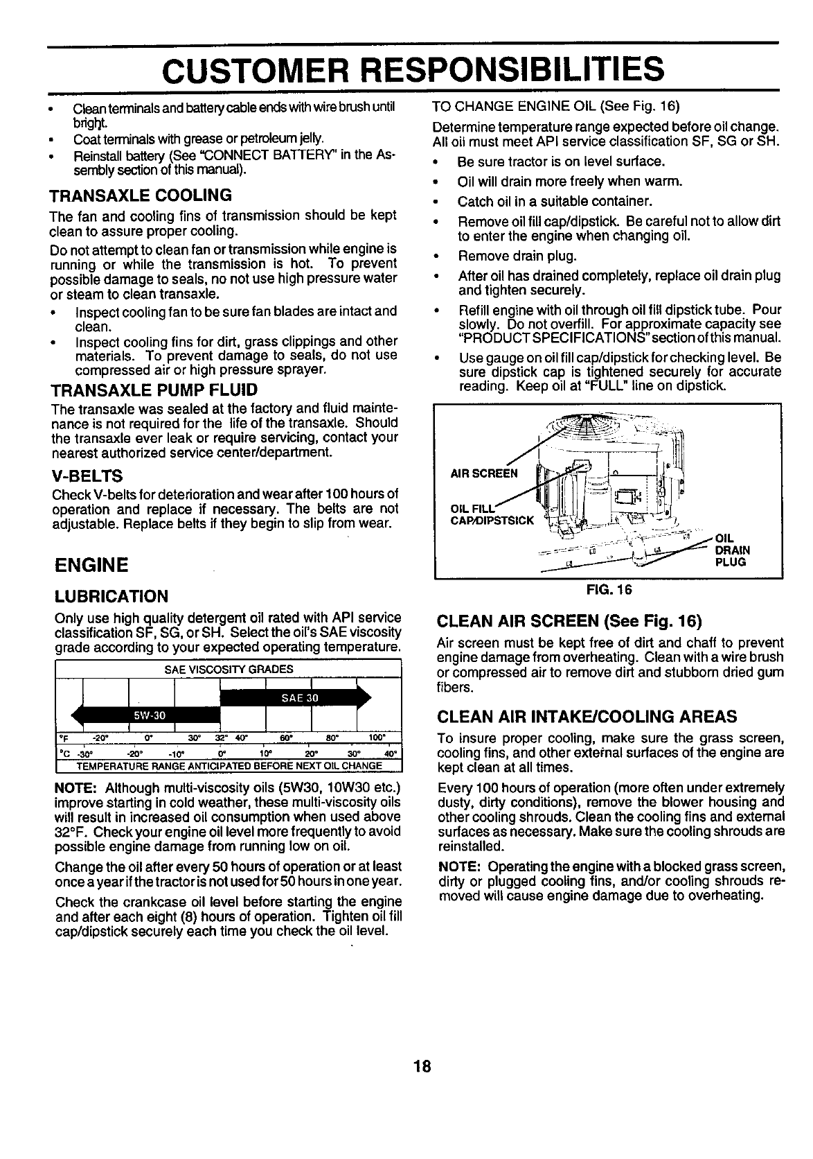
LU BRICATION
Only use high quality detergent oil rated with API service
classification SF, SG, or SH. Select the oil's SAE viscosity
grade according to your expected operating temperature.
SAE VISCOSITY GRADES
-20" 0" 30"
-30" -20° -10°0" 10" 20° 30"
TEMPERATURE RANGE ANTICIPATED BEFORE NEXT OIL CHANGE
NOTE: Although multi-viscosity oils (5W30, 10W30 etc.)
improve starting in cold weather, these multi-viscosity oils
will result in increased oil consumption when used above
32°F. Check your engine oil level more frequently to avoid
possible engine damage from running low on oil.
Change the oil after every 50 hours of operation or at least
once ayear ifthe tractor is notused for 50 hoursinone year.
Check the crankcase oil level before starting the engine
and after each eight (8) hours of operation. Tighten oil fill
cap/dipstick securely each time you check the oil level.
Determine temperature range expected before oil change.
All oil must meet API service classification SF, SG or SH.
• Be sure tractor is on level surface.
•Oil will drain more freely when warm.
• Catch oil in a suitable container.
• Remove oil fill cap/dipstick. Be careful not to allow dirt
to enter the engine when changing oil
Remove drain plug.
After oil has drained completely, replace oil drain plug
and tighten securely.
• Refill engine with oil through oil fill dipstick tube. Pour
slowly. Do not overfill. For approximate capacity see
"PRODUCT SPEClFICATIONS"section of this manual.
Use gauge on oil fill cap/dipstick for checking level. Be
sure dipstick cap is tightened securely for accurate
reading. Keep oil at "FULL" line on dipstick.
,- !1
AIR SCREEN |l _-.,J_-___-J_,, _
...._..._q....-__ PLUG
FIG. 16
CLEAN AIR SCREEN (See Fig. 16)
Air screen must be kept free of dirt and chaff to prevent
engine damage from overheating. Clean with a wire brush
or compressed air to remove dirt and stubborn dried gum
fibers.
CLEAN AIR INTAKE/COOLING AREAS
To insure proper cooling, make sure the grass screen,
cooling fins, and other external surfaces of the engine are
kept clean at all times.
Every 100 hours of operation (more often under extremely
dusty, dirty conditions), remove the blower housing and
other cooling shrouds. Clean the cooling fins and external
surfaces as necessary. Make sure the cooling shrouds are
reinstalled.
NOTE: Operatingtheenginewithablocked grassscreen,
dirty or plugged cooling fins, and/or cooling shrouds re-
moved will cause engine damage due to overheating.
18
CUSTOMER RESPONSIBILITIES
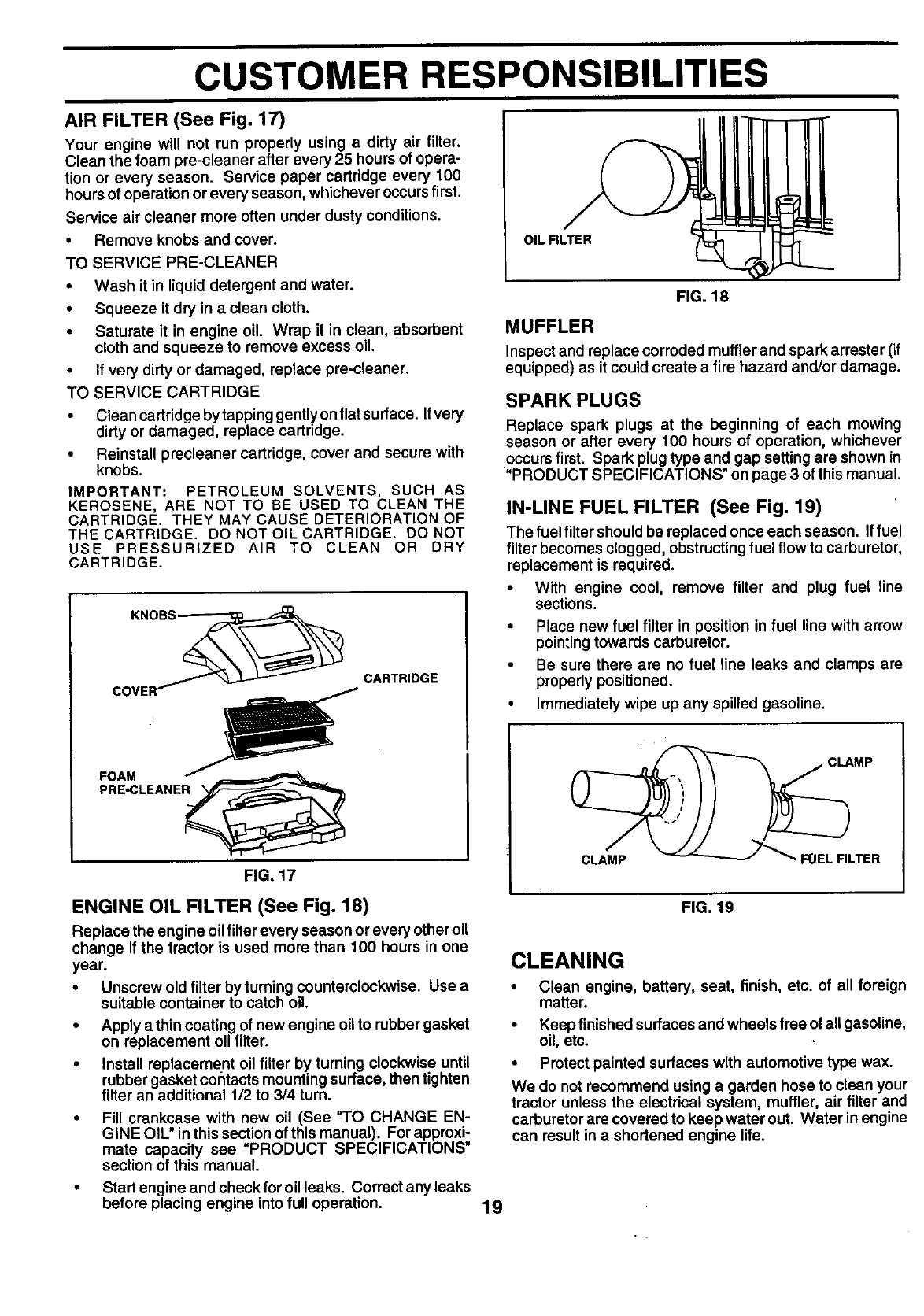
AIR FILTER (See Fig. 17)
Your engine will not run properly using a dirty air filter.
Clean the foam pre-cleaner after every 25 hours of opera-
tion or every season. Service paper cartridge every 100
hours of operation or every season, whichever occurs first.
Service air cleaner more often under dusty conditions.
• Remove knobs and cover.
TO SERVICE PRE-CLEANER
•Wash it in liquid detergent and water.
•Squeeze it dry in a clean cloth.
• Saturate it in engine oil. Wrap it in clean, absorbent
cloth and squeeze to remove excess oil.
• If very dirty or damaged, replace pre-cleaner.
TO SERVICE CARTRIDGE
• Cieancartridgebytappinggentlyonflatsurface. Ifvery
dirty or damaged, replace cartddge.
• Reinstall precleaner cartridge, cover and secure with
knobs.
IMPORTANT: PETROLEUM SOLVENTS, SUCH AS
KEROSENE, ARE NOT TO BE USED TO CLEAN THE
CARTRIDGE. THEY MAY CAUSE DETERIORATION OF
THE CARTRIDGE. DO NOT OIL CARTRIDGE. DO NOT
USE PRESSURIZED AIR TO CLEAN OR DRY
CARTRIDGE.
FOAM
PRE-CLEANER_
FIG, 17
CARTRIDGE
ENGINE OIL FILTER (See Fig. 18)
Replace the engine oil filter every season or every other oil
change if the tractor is used more than 100 hours in one
year.
•Unscrew old fUter by turning countemlockwise. Usea
suitable container to catch oil.
•Apply a thin coating of new engine oil to rubber gasket
on replacement oil filter.
• Install replacement oil filter by turning clockwise until
rubber gasket corltacts mounting surface, then tighten
filter an additional 1/2 to 3/4 turn.
Fill crankcase with new oil (See "TO CHANGE EN-
GINE OiL" inthis section of this manual). For approxi-
mate capacity see "PRODUCT SPECIFICATIONS"
section of this manual.
•Startengineandcheckforoilleaks. Correct any leaks
before placing engine into full operation.
OIL RLTER
FIG. 18
MUFFLER
Inspect and replace corroded muffler and spark arrester (if
equipped) as it could create a fire hazard and/or damage.
SPARKPLUGS
Replace spark plugs at the beginning of each mowing
season or after every 100 hours of operation, whichever
occurs first. Spark plug type and gap setting are shown in
"PRODUCT SPECIFICATIONS" on page 3 of this manual.
IN-LINE FUEL FILTER (See Fig. 19)
The fuel filter should be replaced once each season. If fuel
filter becomes clogged, obstructing fuel flow to carburetor,
replacement is required.
•With engine cool, remove filter and plug fuel line
sections.
• Place new fuel filter in position in fuel line with arrow
pointing towards carburetor.
Be sure there are no fuel line leaks and clamps are
properly positioned.
•Immediately wipe up any spilled gasoline.
;LAMP
CLAMP ,FUEL FILTER
FIG. 19
CLEANING
• Clean engine, battery, seat, finish, etc. of all foreign
matter.
• Keep finished surfaces and wheels free of all gasoline,
oil, etc.
•Protect painted surfaces with automotive type wax.
We do not recommend using a garden hose to clean your
tractor unless the electrical system, muffler, air filter and
carburetor are covered to keep water out. Water in engine
can result in a shortened engine life.
19
SERVICE AND ADJUSTMENTS
CAUTION: BEFORE PERFORMING ANY SERVICE OR ADJUSTMENTS:
Depress clutch/brake pedal fully and set parking brake.
Place motion control lever in neutral (N) position.
Place attachment clutch in "DISENGAGED" position.
Turn ignition key "OFF" and remove key.
Make sure the blades and all moving parts have completely stopped.
•Disconnect spark plug wire from spark plug and place wire where it cannot come in contact with
plug.
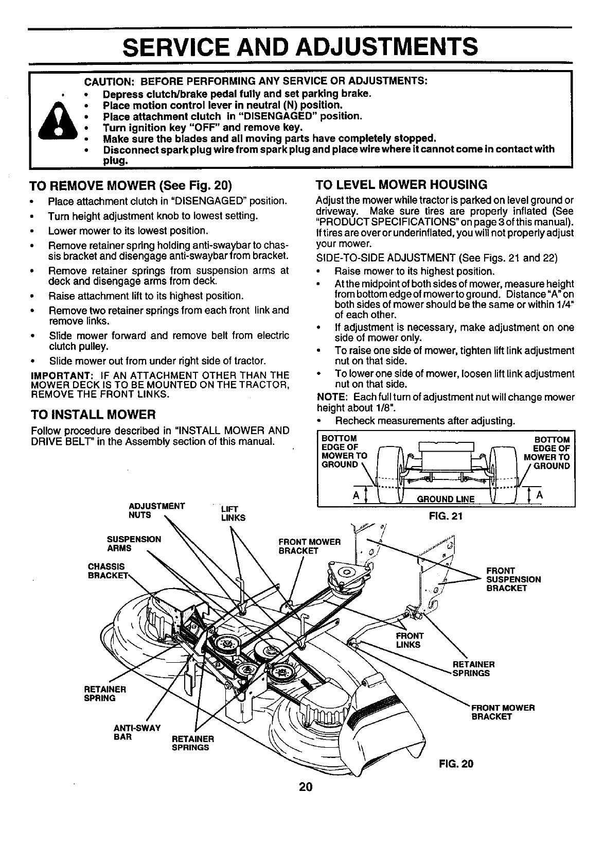
TO REMOVE MOWER (See Fig. 20)
•Place attachment clutch in "DISENGAGED" position.
• Turn height adjustment knob to lowest setting.
• Lower mower to its lowest position.
• Remove retainer spring holding anti-swaybar to chas-
sis bracket and disengage anti-swaybar from bracket.
• Remove retainer spdngs from suspension arms at
deck and disengage arms from deck.
• Raise attachment lift to its highest position.
• Remove two retainer spdngs from each front link and
remove links.
• Slide mower forward and remove belt from electdc
clutch pulley.
• Slide mower out from under right side of tractor.
IMPORTANT: IF AN ATTACHMENT OTHER THAN THE
MOWER DECK IS TO BE MOUNTED ON THE TRACTOR,
REMOVE THE FRONT LINKS.
TO INSTALL MOWER
Follow procedure described in "INSTALL MOWER AND
DRIVE BELT" in the Assembly section of this manual.
ADJUSTMENT LIFT
NUTS LINKS
SUSPENSION
ARMS
CHASSIS
TO LEVEL MOWER HOUSING
Adjustthe mower while tractor is parked on level ground or
driveway. Make sure tires are properly inflated (See
"PRODUCT SPECIFICATIONS" on page 3 ofthis manual).
If tires are overor underinflated, you will not properly adjust
your mower.
SIDE-TO-SIDE ADJUSTMENT (See Figs. 21 and 22)
Raise mower to its highest position.
At the midpointof both sides of mower, measure height
from bottomedge of mower to ground. Distance"A" on
both sides of mower should be the same or within 1/4"
of each other.
•If adjustment is necessary, make adjustment on one
side of mower only.
To raise one side of mower, tighten liftlink adjustment
nut on that side.
To lower one side of mower, loosen lift link adjustment
nut on that side.
NOTE: Each full turn of adjustment nut will change mower
height about 1/8".
•Recheck measurements after adjusting.
BOTTOM BoI-rOM
EDGE OF /'-I"h _ _ EDGE OF
MOWER TO II1_ _11 _ MOWER TO
GBO "D',NE
FIG. 21
/
FRONT MOWER
BRACKET
FRONT
SUSPENSION
BRACKET
RETAINER
SPRING
ANTI-SWAY
BAR RETAINER
SPRINGS
RETAINER
"SPRINGS
BRACKET
FIG. 20
20
SERVICE AND ADJUSTMENTS
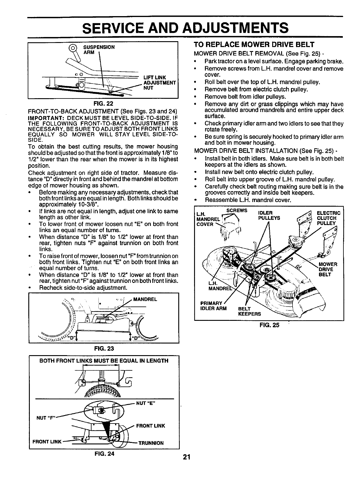
TO REPLACE MOWER DRIVE BELT
_0 ARMSUSPENSION
LIFTLINK
JL AO,OSTM°NT
NUT
FIG. 22
FRONT-TO-BACK ADJUSTMENT (See Figs. 23 and 24)
IMPORTANT: DECK MUST BE LEVEL SIDE-TO-SIDE. IF
THE FOLLOWING FRONT-TO-BACK ADJUSTMENT IS
NECESSARY, BE SURE TO ADJUST BOTH FRONT LINKS
EQUALLY SO MOWER WILL STAY LEVEL SIDE-TO-
SIDE.
To obtain the best cutting results, the mower housing
should be adjusted so that the front is approximately 1/8" to
1/2" lower than the rear when the mower is in its highest
position.
Check adjustment on right side of tractor. Measure dis-
tance "D" directly in front and behind the mandrel at bottom
edge of mower housing as shown.
• Before making any necessary adjustments, check that
both front links are equal in length. Both links should be
approximately 10-3/8".
•If links are not equal in length, adjust one link to same
length as other link.
To lower front of mower loosen nut "E" on both front
links an equal number of turns.
When distance "D" is 1/8" to 1/2" lower at front than
rear, tighten nuts "F" against trunnion on both front
links.
• To raise front of mower, loosen nut "F" from trunnion on
both front links. Tighten nut "E" on both front links an
equal number of turns.
• When distance "D" is 1/8" to 1/2" lower at front than
rear, tighten nut "F" against trunnion on both front links.
• Recheck side-to-side adjustment.
MOWER DRIVE BELT REMOVAL (See Fig. 25) -
• Park tractor on a level surface. Engage parking brake.
• Remove screws from L.H. mandrel cover and remove
cover.
•Roll belt over the top of L.H. mandrel pulley.
• Remove belt from electric clutch pulley.
•Remove belt from idler pulleys.
•Remove any dirt or grass clippings which may have
accumulated around mandrels and entire upper deck
surface.
•Check primary idler arm and two idlersto see that they
rotate freely.
•Be sure spring is securely hooked to primary idler arm
and bolt in mower housing.
MOWER DRIVE BELT INSTALLATION (See Fig. 25) -
•Installbelt in both idlers. Make sure belt is in both belt
keepers at the idlers as shown.
Install new belt onto electric clutch pulley.
•Roll belt into upper groove of L.H. mandrel pulley.
•Carefully check belt routing making sure belt is in the
grooves correctly and inside belt keepers.
•Reassemble LH. mandrelcover.
I
SCREWS
LH. r------------7_ IDLER ELECTRIC
MANDRELI_._ PULLEYS CLUTCH
COVER'_--_-- ;. PULLEY
L.H.
MOWER
BELT
PRIMARY
IDLER ARM BELT
KEEPERS
FIG. 25
FIG. 23
BOTH FRONT LINKS MUST BE EQUAL IN LENGTH
NUT "E"
NUT"F"_ _
_FRONTLINK
FRONTLINK__TRUNNION
FIG. 24 21
SERVICE AND ADJUSTMENTS
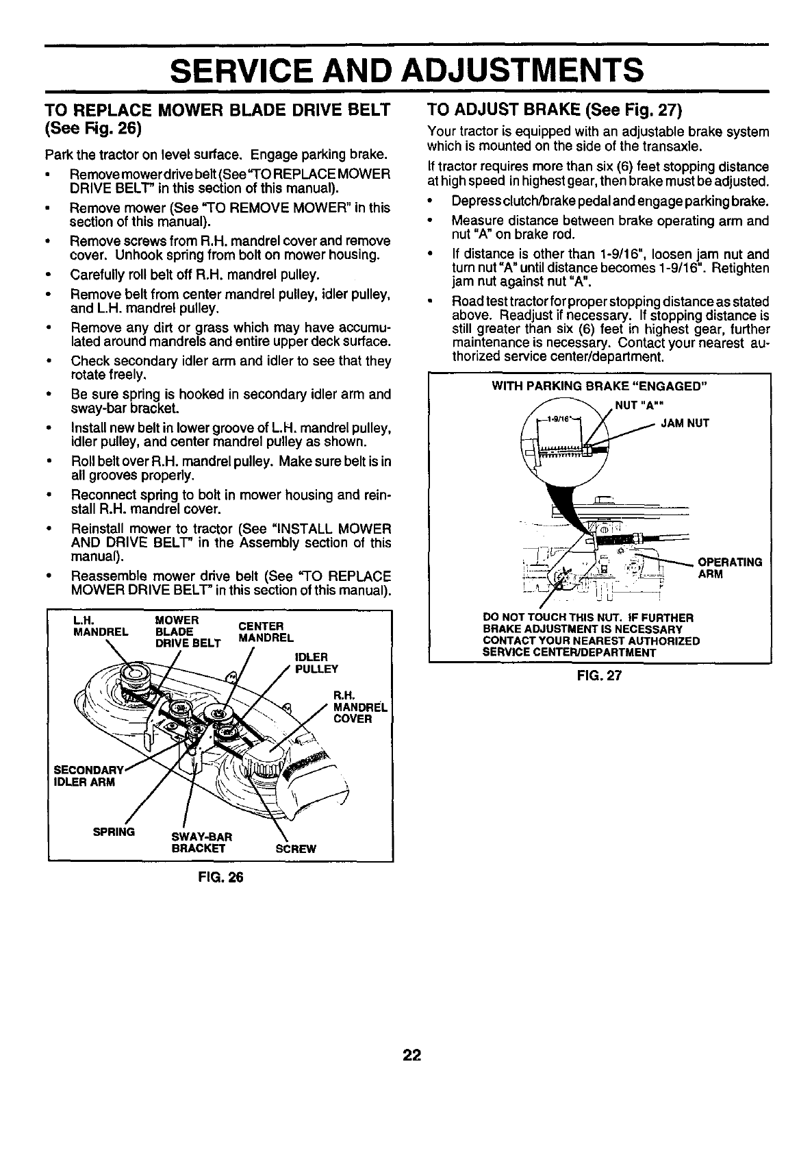
TO REPLACE MOWER BLADE DRIVE BELT
(See Fig. 26)
Park the tractor on level surface. Engage parking brake.
•Remove mower drive belt(See "TO REPLACE MOWER
DRIVE BELT" in this section of this manual).
Remove mower (See "TO REMOVE MOWER" in this
section of this manual).
•Remove screws from R.H. mandrel cover and remove
cover. Unhook spring from bolt on mower housing.
•Carefully roll belt off R.H. mandrel pulley.
•Remove belt from center mandrel pulley, idler pulley,
and L.H. mandrel pulley,
•Remove any dirt or grass which may have accumu-
lated around mandrels and entire upper deck surface.
• Check secondary idler arm and idler to see that they
rotate freely.
• Be sure spring is hooked in secondary idler arm and
sway-bar bracket.
•Install new belt in lower groove of L.H. mandrel pulley,
idler pulley, and center mandrel pulley as shown.
•Roll belt over R.H. mandrel pulley. Make sure belt is in
all grooves properly.
•Reconnect spring to bolt in mower housing and rein-
stall R.H. mandrel cover.
• Reinstall mower to tractor (See =INSTALL MOWER
AND DRIVE BELT" in the Assembly section of this
manual).
•Reassemble mower drive belt (See "TO REPLACE
MOWER DRIVE BELT" in this section of this manual).
ILH. MOWER
MANDREL BLADE CENTER
DRIVEBELT MANDREL
IDLER I
PULLEY
RoHo
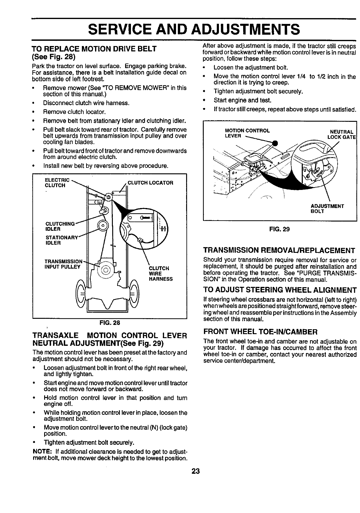
TO ADJUST BRAKE (See Fig. 27)
Your tractor is equipped with an adjustable brake system
which is mounted on the side of the transaxle.
if tractor requires more than six (6) feet stopping distance
at highspeed in highestgear, then brake must be adjusted.
•Depress clutch/brake pedal and engage parking brake.
•Measure distance between brake operating arm and
nut "A" on brake rod.
If distance is other than 1-9/16", loosen jam nut and
turn nut "A" until distance becomes 1-9/16". Retighten
jam nut against nut "A".
Road test tractor for proper stopping distance as stated
above. Readjust if necessary. If stopping distance is
still greater than six (6) feet in highest gear, further
maintenance is necessary. Contact your nearest au-
thorized service center/department.
WITH PARKING BRAKE "ENGAGED"
NUT "A""
OPERATING
ARM
DO NOT TOUCH THIS NUT. IF FURTHER
BRAKE ADJUSTMENT IS NECESSARY
CONTACT YOUR NEAREST AUTHORIZED
SERVICE CENTER/DEPARTMENT
FIG. 27
IDLER ARM
SPRING SWAY-BAR
BRACKET
FIG. 26
SCREW
22
SERVICE AND ADJUSTMENTS
TO REPLACE MOTION DRIVE BELT
(See Fig. 28)
Park the tractor on level surface. Engage parking brake.
For assistance, there is a belt installation guide decal on
bottom side of left footrest.
•Remove mower (See "TO REMOVE MOWER" in this
section of this manual.)
•Disconnect clutch wire harness.
•Remove clutch Iocator.
• Remove belt from stationary idler and clutching idler.
•Pull belt slack toward roar of tractor. Carefully remove
belt upwards from transmission input pulley and over
cooling fan blades.
•Pull belttoward front of tractor and remove downwards
from around electric clutch.
•Install new belt by reversing above procedure.
ELECTRIC -_
CLUTCH
JP
CLUTCHING /
IDLER
STATIONARY j
IDLER
TRANSMISSION __ ............
INPUT PULLEY f,:::'i"_
R
CLUTCH
WIRE
HARNESS
FIG. 28
TRANSAXLE MOTION CONTROL LEVER
NEUTRAL ADJUSTMENT(See Fig. 29)
The motion control lever has been preset at the factory and
adjustment should not be necessary.
•Loosen adjustment bolt in front of the dght rear wheel,
and lightly tighten.
•Start engine and move motioncontrol lever untiltractor
does not move forward or backward.
•Hold motion control lever in that position and turn
engine off.
While holding motion control lever inplace, loosen the
adjustment bolt.
•Move motion control lever to the neutral (N) (lock gate)
position.
•Tighten adjustment bolt securely.
NOTE: If additional clearance is needed to get to adjust-
ment •bolt, move mower deck height to the lowest position.
After above adjustment is made, if the tractor still creeps
forward or backward while motion control lever is in neutral
position, follow these steps:
Loosen the adjustment bolt.
• Move the motion control lever 1/4 to 1/2 inch in the
direction it is trying to creep.
• Tighten adjustment bolt securely.
•Start engineand test.
•If tractor stillcreeps, repeat above steps untilsatisfied.
MOTION CONTROL NEUTRAL
LEVER LOCK GATE
ADJUSTMENT
BOLT
FIG. 29
TRANSMISSION REMOVAL/REPLACEMENT
Should your transmission require removal for service or
replacement, it should be purged after reinstallation and
before operating the tractor. See "PURGE TRANSMIS-
SION" in the Operation section of this manual.
TO ADJUST STEERING WHEEL ALIGNMENT
If steering wheel crossbars are not horizontal (left to right)
when wheels are positioned straightforward, remove steer-
ingwheel and reassemble per instructions inthe Assembly
section of this manual.
FRONT WHEEL TOE-IN/CAMBER
The front wheel toe-in and camber are not adjustable on
your tractor. If damage has occurred to affect the front
wheel toe-in or camber, contact your nearest authorized
service center/department.
23
SERVICE AND ADJUSTMENTS
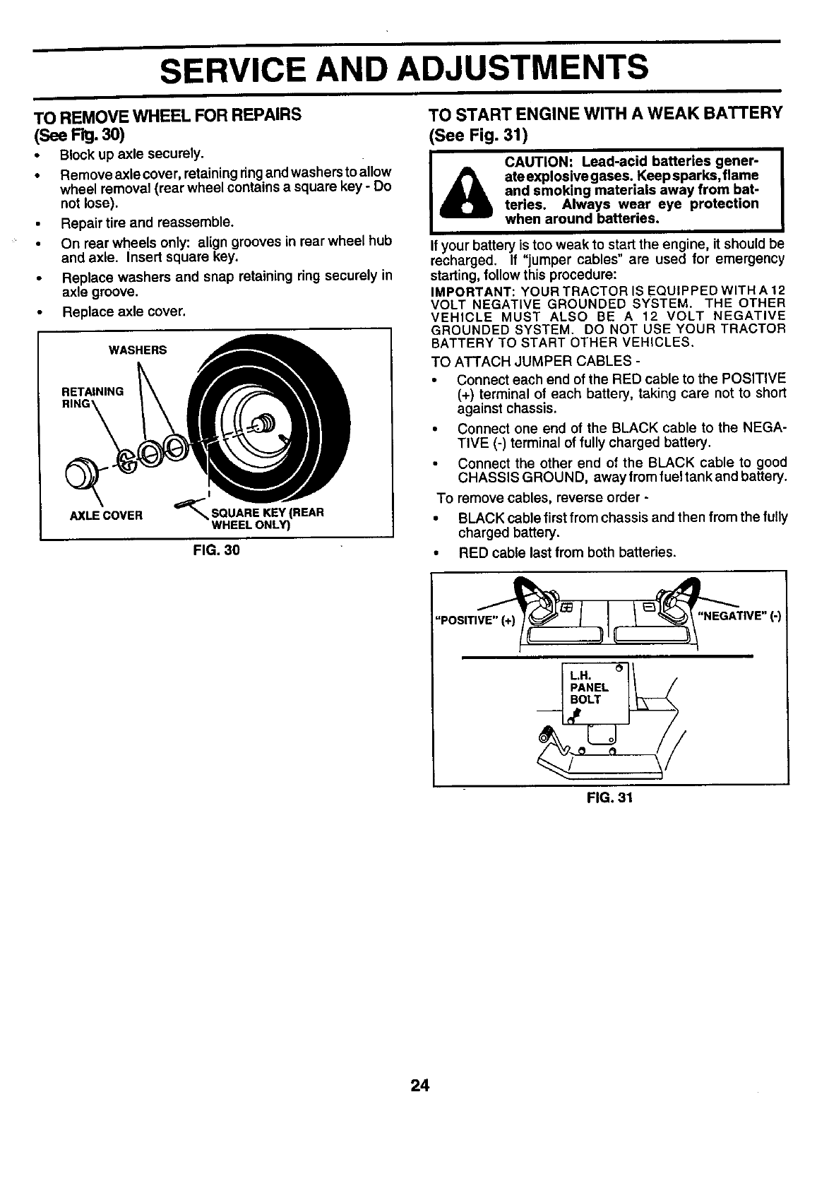
TO REMOVE WHEEL FOR REPAIRS
(See Fig. 30)
•Block up axle securely.
•Remove axle cover, retaining ringand washers to allow
wheel removal (rear wheel contains a square key - Do
not lose).
•Repair tire and reassemble.
•On rear wheels only: align grooves in rear wheel hub
and axle. Insert square key.
•Replace washers and snap retaining ring securely in
axle groove.
Replace axle cover.
WASHERS
RETAINING
AXLE COVER '_SQUARE KEY(REAR
WHEEL ONLY)
FIG. 30
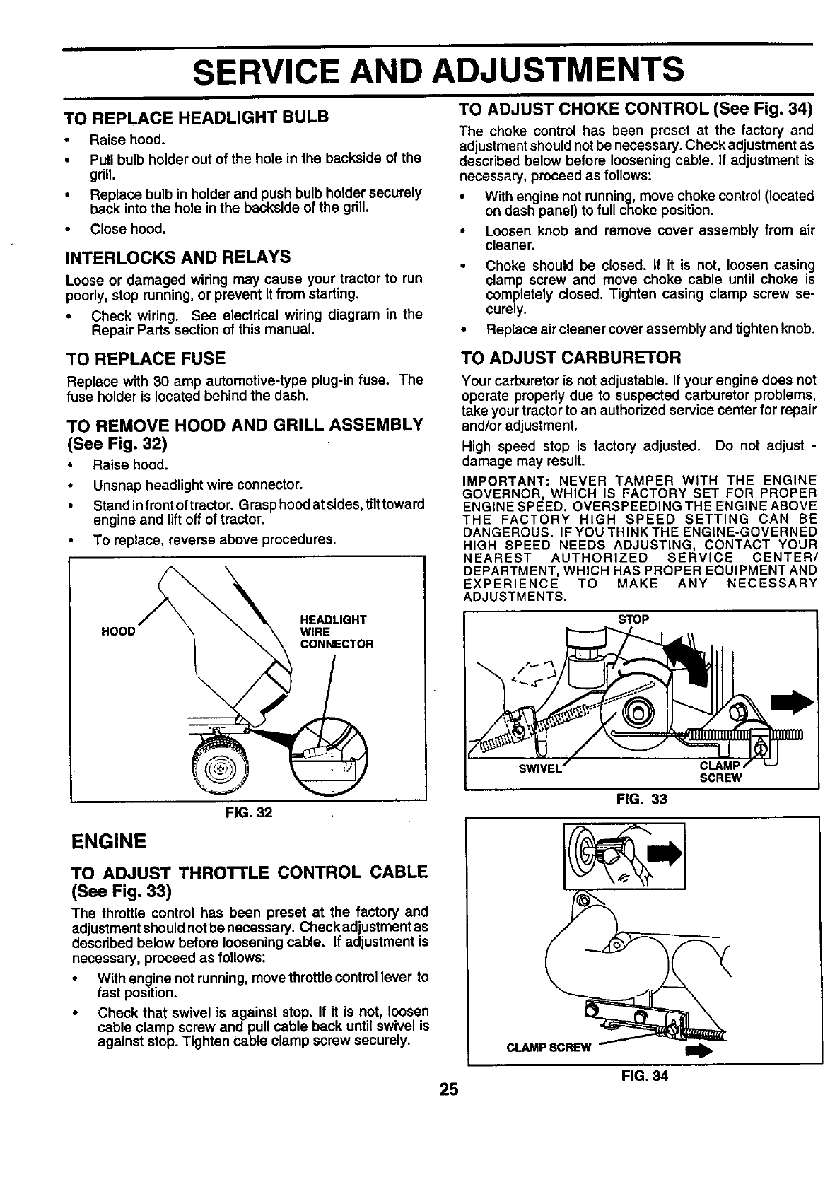
TO START ENGINE WITH A WEAK BATTERY
(See Fig. 31)
I CAOT'O"''eadacidba"er'esgene'[
ate explosive gases. Keep sparks, flame
and smoking materials away from bat-
teries. Always wear eye protection
when around batteries.
If your battery is too weak to start the engine, it should be
recharged. If "jumper cables" are used for emergency
starting, follow this procedure:
IMPORTANT: YOUR TRACTOR IS EQUIPPED WITH A 12
VOLT NEGATIVE GROUNDED SYSTEM. THE OTHER
VEHICLE MUST ALSO BE A 12 VOLT NEGATIVE
GROUNDED SYSTEM. DO NOT USE YOUR TRACTOR
BATTERY TO START OTHER VEHICLES.
TO ATTACH JUMPER CABLES -
• Connect each end of the RED cable to the POSITIVE
(+) terminal of each battery, taking care not to short
against chassis.
• Connect one end of the BLACK cable to the NEGA-
TIVE (-) terminal of fully charged battery.
• Connect the other end of the BLACK cable to good
CHASSIS GROUND, away from fuel tank and battery.
To remove cables, reverse order -
• BLACK cable first from chassis and then from the fully
charged battery.
• RED cable last from both batteries.
FIG. 31
24
SERVICE AND ADJUSTMENTS
TO REPLACE HEADLIGHT BULB
• Raise hood.
•Pull bulb holder out of the hole in the backside of the
grill.
•Replace bulb in holder and push bulb holder securely
back into the hole in the backside of the grill.
•Close hood.
INTERLOCKS AND RELAYS
Loose or damaged wiring may cause your tractor to run
poorly, stop running, or prevent it from starting.
•Check wiring. See electrical wiring diagram in the
Repair Parts section of this manual.
TO ADJUST CHOKE CONTROL (See Fig. 34)
The choke control has been preset at the factory and
adjustment should not be necessary. Check adjustment as
described below before loosening cable. If adjustment is
necessary, proceed as follows:
• With engine not running, move choke control (located
on dash panel) to full choke position.
• Loosen knob and remove cover assembly from air
cleaner.
• Choke should be closed. If it is not, loosen casing
clamp screw and move choke cable until choke is
completely closed. Tighten casing clamp screw se-
curely.
• Replace air cleaner cover assembly and tighten knob.
TO REPLACE FUSE
Replace with 30 amp automotive-type plug-in fuse. The
fuse holder is located behind the dash.
TO REMOVE HOOD AND GRILL ASSEMBLY
(See Fig. 32)
•Raise hood.
•Unsnap headlight wire connector.
•Stand infrent of tractor. Grasp hood at sides, tilttoward
engine and lift off of tractor.
•To replace, reverse above procedures.
HOOD HEADLIGHT
WIRE
CONNECTOR
FIG. 32
ENGINE
TO ADJUST THROTTLE CONTROL CABLE
(See Fig. 33)
The throttle control has been preset at the factory and
adjustment should notbe necessary. Check adjustment as
described below before loosening cable. If adjustment is
necessary, proceed as follows:
•With engine not running, move throttlecontrol lever to
fast position.
•Check that swivel is against stop. If it is not, loosen
cable clamp screw and pull cable back until swivel is
against stop. Tighten cable clamp screw securely.
TO ADJUST CARBURETOR
Your carburetor is not adjustable. If your engine does not
operate properly due to suspected carburetor problems,
take your tractor to an authorized service center for repair
and/or adjustment.
High speed stop is factory adjusted. Do not adjust -
damage may result.
IMPORTANT: NEVER TAMPER WITH THE ENGINE
GOVERNOR, WHICH IS FACTORY SET FOR PROPER
ENGINE SPEED. OVERSPEEDING THE ENGINE ABOVE
THE FACTORY HIGH SPEED SETTING CAN BE
DANGEROUS. IF YOU THINK THE ENGINE-GOVERNED
HIGH SPEED NEEDS ADJUSTING, CONTACT YOUR
NEAREST AUTHORIZED SERVICE CENTER/
DEPARTMENT, WHICH HAS PROPER EQUIPMENT AND
EXPERIENCE TO MAKE ANY NECESSARY
ADJUSTMENTS.
STOP
SWIVEL CLAMF
SCREW
FIG. 33
CLAMP SCREW
FIG.34
25
STORAGE
ENGINEImmediately prepare your tractor for storage at the end of
the season or if the tractor will not be used for 30 days or
_ore.
ACAUTION: Never store the tractor with
gasoline in the tank inside a building
where fumes may reach an open flame
or spark. Allow the engine to cool
before storing in any enclosure.
TRACTOR
Remove mower from tractor for winter storage. When
mower is to be stored for a pedod of time, clean it thor-
oughly, remove all dirt, grease, leaves, etc. Store in a
clean, dry area.
•Clean entire tractor (See"CLEANING" inthe Customer
Responsibilities section of this manual).
•Inspect and replace belts, if necessary (See belt re-
placement instructions in the Service and Adjustments
section of this manual).
• Lubricate as shown in the Customer Responsibilities
section of this manual.
• Be sure that all nuts, bolts end screws are securely
fastened. Inspect moving parts for damage, breakage
and wear. Replace if necessary.
• Touch up all rusted or chipped paint surfaces; sand
lightly before painting.
BATTERY
•Fully charge the battery for storage.
• After a pedod of time in storage, battery may require
recharging.
To help prevent corrosion and power leakage during
long periods of storage, battery cables should be
disconnected and battery cleaned thoroughly (see "TO
CLEAN BATTERY AND TERMINALS" in the Cus-
tomer Responsibilities section of this manual).
•After cleaning, leave cables disconnected and place
cables where they cannot come incontact with battery
terminals.-
•If battery is removed from tractor for storage, do not
store battery directly on concrete or damp surfaces.
FUEL SYSTEM
IMPORTANT: IT IS IMPORTANT TO PREVENT GUM
DEPOSITS FROM FORMING IN ESSENTIAL FUEL
SYSTEM PARTS SUCH AS CARBURETOR, FUEL FILTER,
FUEL HOSE, OR TANK DURING STORAGE. ALSO,
EXPERIENCE INDICATES THAT ALCOHOL BLENDED
FUELS (CALLED GASOHOL OR USING ETHANOL OR
METHANOL) CAN ATTRACT MOISTURE WHICH LEADS
TO SEPARATION AND FORMATION OF ACIDS DURING
STORAGE. ACIDIC GAS CAN DAMAGE THE FUEL
SYSTEM OF AN ENGINE WHILE IN STORAGE.
• Drain the fuel tank.
•Start the engine and let it run until the fuel lines and
carburetor are empty.
• Never use engine or carburetor cleaner products in the
fuel tank or permanent damage may occur.
• Use fresh fuelnext season.
NOTE: Fuel stabilizer is an acceptable alternative in
minimizing the formation of fuel gum deposits during stor-
age. Add stabilizer to gasoline in fuel tank or storage
container. Always follow the mix ratio found on stabilizer
container. Run engine at least 10 minutes after adding
stabilizer to allow the stabilizer to reach the carburetor. Do
not drain the gas tank and carburetor if using fuel stabilizer.
ENGINE OIL
Drain oil (with engine warm) and replace with clean engine
oil. (See "ENGINE" in the Customer Responsibilities
section of this manual).
CYLINDER(S)
• Remove spark plug(s).
Pour one ounce of oil through spark plug hole(s) into
cylinder(s).
Tum ignitionkey to"START" positionfora few seconds
to distribute oil
• Replace with new spark plug(s).
OTHER
•Do not store gasoline from one season to another.
•Replace your gasoline can if your can starts to rust.
Rust and/or dirt in your gasoline will cause problems.
• If possible, store your tractor indoors and cover it to
give protectionfrom dust and dirt.
•Cover your tractor with a suitable protective cover that
does not retain moisture. Do not use plastic. Plastic
cannot breathe which allows condensation to form and
will cause your tractor to rust.
IMPORTANT: NEVER COVER TRACTOR WHILE ENGINE
AND EXHAUST AREAS ARE STILL WARM.
26

TROUBLESHOOTING POINTS
PROBLEM
wig not start
Herd to start
Engine will not turn over
Engine clicks but will not
start
Loss of power
Excessive vibration
CAUSE
1. Out of fuel.
2. Enginenot=CHOKED"propedy.
3. Engineflooded.
4. Badsparkplug,
5. Dirtyairfilter.
6. Dirtyfuelfilter,
7. Water infuel.
8. Loose or damaged widng.
9. Carburetor out of adjustment.
t0. Enginevalvesoutof adjustment.
1. Dirty air filter.
2. Bad spark plug.
3. Weak or dead battery.
4. Dirty fuel filter.
5. Stale or dirty fuel.
6. Loose or damaged wiring.
7. Carburetor out of adjustment.
8. Engine valves out of adjustment.
1, Clutchrbrake pedal not depressed.
2. Attachment clutch is engaged.
3. Weak or dead battery.
4. Blown fuse.
5. Corroded battery terminals.
6. Loose or damaged widng.
7, Faulty ignition switch.
8. Faulty solenoid or starter.
9. Faulty operator presence switch(es).
1, Weak ordead battery.
2. Corrodedbatteryterminals.
3. Looseor damagedwiring.
4. Faultysolenoidorstarter.
1. Cutting too much grass/too fast.
2. Throttle in "CHOKE" position.
3, Build-up of grass, leaves and trash under mower.
4. Dirty air filter.
5. Low oil level/dirty oil.
6. Faulty spark plug.
7. Dirty fuel filter.
8, Stale or dirty fuel.
9, Water in fuel.
10, Spark plug wire loose.
11, Dirty engine air screen/fins.
12. Dirty/clogged muffler.
13. Loose or damaged widng.
14. Carburetor out of adjustment.
15. Enginevalvesout of adjustment.
1. Wom, bentor looseblade.
2. Bentblade mandrel.
3. Loose/damagedpart(s).
CORRECTION
1. Fillfuel tank.
2. See =TOSTART ENGINE"in Operationsection.
3. Waitseveralminutesbeforeattemptingto start.
4. Replacesparkplug.
5, Clean/replaceairfilter.
6. Replacefuel filter.
7. Drainfuel tankand carburetor,refilltank withfresh
gasolineand replacefuelfilter.
8. Checkallwidng.
9. See =ToAdjustCarburetor"inServiceAdjustments
section.
t0. Contact an authorizedservicecenter/department.
1. Clean/replace air filter,
2. Replace spark plug.
3. Recharge or replace battee/.
4, Replace fuel filter.
5. Drain fuel tank and refill with fresh gasoline.
6. Check all widng.
7. See =To Adjust Carburetor" in Service Adjustments
section.
8. Contact an authorized service centerldepartment.
1. Depress clutch/brake pedal.
2. Disengage attachment clutch.
3. Recharge or replace battery.
4. Replace fuse.
5. Clean battery terminals.
6. Check all widng.
7, Check/replace ignition switch.
8. Check/raplace solenoid or starter.
9. Contact an authorized service center/departmant.
1, Recharge or replace battery.
2. Clean battery terminals.
3. Check all widng.
4. Check/replace solenoid or starter.
1. Set in "HigherCut"position/reducespeed,
2. Adjustthrottle contro!.
3. Clean undersideof mowerhousing.
4. Cleaniraplaceairfilter.
5. Checkoillevel/changeoil.
6. Clean and regaporchangesparkplug.
7, Replacefuel filter,
8. Drainfuel tank and refillwithfresh gasoline.
9. Drainfuel tank andcarburetor,refilltank withfresh
gasolineand replacefuel filter,
10. Connectand tightensparkplugwire.
11. Clean engineair screen/fins.
12. Cleardraplecemuffler.
13. Checkallwidng.
14. See "To AdjustCarburetor"in ServiceAdjustments
section.
15. Contact an authorizedservicecenter/department.
t. Replace blade. Tighten bladebolt.
2. Replaceblademandrel.
3. Tightenloosepart(s). Replace damagedparts.
27
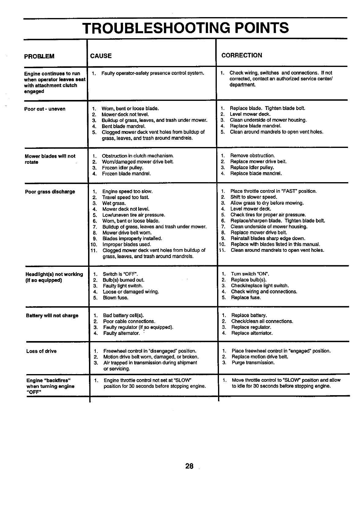
TROUBLESHOOTING POINTS
PROBLEM
Engine continues to run
when operator leaves seat
with attachment clutch
engaged
Poorcut-uneven
Mower bledeswilt not
rotate
Poor grass dlscharge
Headlight(s) not working
(if so equipped)
Battery will not charge
Loss of drive
Engine "backfires"
when turning engine
"OFF"
CAUSE
1. Faulty operator-safety presence control system.
1. Worn, bent or loose blade.
2. Mower deck not level.
3. Buildup of grass, leaves, and trash under mower.
4, Bent blade mandrel.
5. C_ogged mower deck vent holes from buildup of
grass, leaves, and trash around mandrels.
1. Obstructioninclutchmechanism.
2. Worn/damagedmowerdrivebelt.
3. Frozenidlerpulley.
4. Frozenblademandrel.
1. Enginespeedtooslow.
2. Travelspeedtoofast.
3. Wet grass.
4. Mowerdeck notlevel.
5. Lowluneventire airpressure.
6. Worn, bentor looseblade.
7. Buildup of grass,leavesand trashundermower.
8. Mower ddvebeltworn.
9. Bladesimproperlyinstalled.
10. Improperbladesused.
11. Cloggedmowerdeckventholesfrombuildupof
grass,leaves,andtrasharoundmandrels.
1. Switch is =OFF'.
2. Bulb(s) burned out.
3. Fauity light switch.
4. Loose or damaged widng.
5. Blown fuse.
1. Bad battery call(s).
2. Poor cable connections.
3. Faulty regulator (lt so equipped).
4. Faulty alternator.
1. Freewheel control in "disengaged_position.
2. Motion drive belt worn, damaged, or broken.
3. Air trapped in transmission during shipment
or servicing.
1. Enginethrottlecontrolnotset at =SLOW"
positionfor 30 secondsbeforestoppingengine.
CORRECTION
1. Check wiring, switches and connections. If not
corrected, contact an authorized service center/
department.
1. Replace blade. Tighten blade bolt.
2. Level mower deck.
3. Clean underside of mower housing.
4. Replace blade mandrel.
5. Clean around mandrels to open vent holes.
1. Removeobstruction.
2. Replace mowerdrivebelt.
3. Replaceidlerpulley.
4. Replaceblademandrel.
1. Place thro_e control in "FAST" position.
2. Shift to stower speed.
3. Allow grass to dry before mowing.
4. Level mower deck.
5. Check tires for proper air pressure.
6. Replace/sharpen blade. Tighten blade bolt.
7. Clean underside of mower housing.
8. Replace mower drive belt.
9. Reinstall blades sharp edge down.
10. Replace with blades listed in this manual.
11. Clean around mandrels to open vent holes.
1. Turn switch =ON".
2. Replace bulb(s).
3. Check/replece light switch.
4. Check wiring and connections.
5. Replace fuse.
1. Replacebattery.
2. Check/cleanallconnections.
3. Replaceregulator.
4. Replacealternator.
1. Place freewheel control in =engaged" position.
2. Replace motion drive belt.
3. Purge transmission,
1. Move throttlecontrol to "SLOW"positionand allow
to idlefor 30 secondsbeforestoppingengine.
28

SCHEMATIC
TRACTOR - - MODEL NUMBER 944.609810
t
f,
RED
AMMETER
(OPTIONAL) wHnE
_ BLA_
)G AI_ 1
POSITION CIRCUIT
OFF M+G+A"
RUN/LIGHT B + A1
RUN B + A1
START B + S + A1
IGNITION
SWITCH
11
V
RED (
I
I
l
I
I
I
G
E
I I I
•BLACK IA= I
iP,O
•SEAT SWITCH I(_Q"_ =;
I
(NOT OCCUPIED) [ D J
.....
I1
i _ (DISENGAGED)
II
I I
O Ii GREEN
UEL, l
NE',I
I I BLACK
FUEL SHUT-OFF SOLENOID
BLACK
IGNITION SWITCH
"MAKE"
NONE
A2+L
NONE
NONE
--
/860 8Sl
L30 J
RELAY
SOLENOID
I
BED
I
=STARTER
WHITE BLACK
O: E_.L_EC_T_RI_C_C_I.UTC_H
I " RED I I
FH=
©' I.... ,
I
I1
,85 86 ,
II OPERATOR
O_GE
I_ SPARK
IGNITION PLUGS GAP
UNIT i "_ (2 PLUGS ON
'I'WlN CYL. ENGINES)
CHARGING SYSTEM OUTPUT
(_MP DC @ 3600 RPMREGULATOR YELLOW
28 VOLTS AC @ 3600 RPM
(REGULATOR DISCONNECTED)
BROWN BLACK
HEADLIGHTS
GFC
PTO SWITCH
IPOSITION CIRCUIT
WIRING INSULATED CLIPS IH B
NOTE: IF WIRING INSULATED OFF C+G,B+ H
CLIPS WERE REMOVED FOR ON C+F,B+E,A+D
SERVICING OF UNIT, THEY • O D A
SHOULD BE REPLACED TO
PROPERLY SECURE YOUR WIRING. NON-REMOVABLE
CONNECTIONS REMOVABLE
CONNECTIONS
29
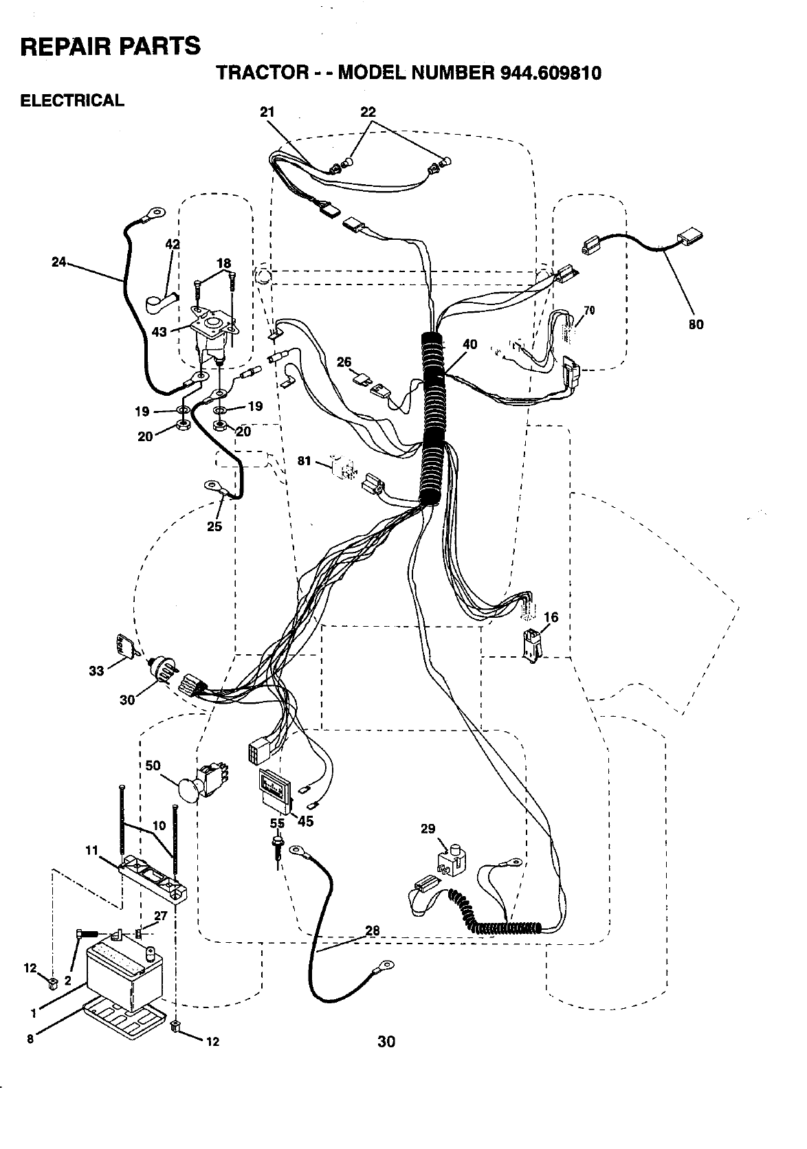
REPAIR PARTS
ELECTRICAL
TRACTOR - - MODEL NUMBER 944.609810
21 22
I \
I I
I I
42I I
18
26
/\
I
I
I/
f/70 80
2O
\
11
I
I
I
I
29
3O
I
I
I
I
\
\
/
/
/
//
/
\
\
\
I
I
I
I
I
I
I
I
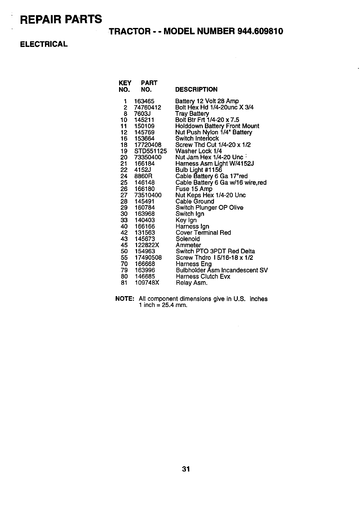
REPAIR PARTS
TRACTOR --MODEL NUMBER 944.609810
ELECTRICAL
KEY PART
NO, NO, DESCRIPTION
1 163465
2 74760412
8 7603J
10 145211
11 150109
12 145769
16 153664
18 17720408
19 STD551125
20 73350400
21 166184
22 4152J
24 8860R
25 146148
26 166180
27 73510400
28 145491
29 160784
30 163968
33 140403
40 166166
42 131563
43 145673
45 122822X
50 154963
55 17490508
70 166668
79 163996
80 146685
81 109748X
Battery 12 Volt 28 Amp
Bolt Hex Hd 1/4-20unc X 314
Tray Battery
Bolt Btr Frt 1/4-20 x 7,5
Holddown Battery Front Mount
Nut Push Nylon 1/4" Battery
Switch Interlock
Screw Thd Cut 1/4-20 x 1/2
Washer Lock 114
Nut Jam Hex 1/4-20 Uric :
Harness Asm Light W/4152J
Bulb Light #1156
Cable Battery 6 Ga 17"red
Cable Battery 6 Ga w/16 wire,red
Fuse 15 Amp
Nut Keps Hex 1/4-20 Unc
Cable Ground
Switch Plunger OP Olive
Switch Ign
Key Ign
Harness Ign
Cover Terminal Red
Solenoid
Ammeter
Switch PTO 3PDT Red Delta
Screw Thdro 15/16-18 x 1/2
Harness Eng
Bulbholder Asm Incandescent SV
Harness Clutch Evx
Relay Asm.
NOTE: All component dimensions give in U.S. inches
1 inch = 25.4 mm.
31
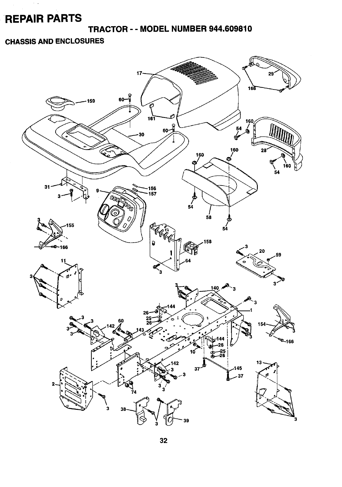
REPAIR PARTS
TRACTOR - - MODEL NUMBER 944.609810
CHASSIS AND ENCLOSURES
31
11
6o
160
160 _/
54
54
/3
3
74 3
38_39
32
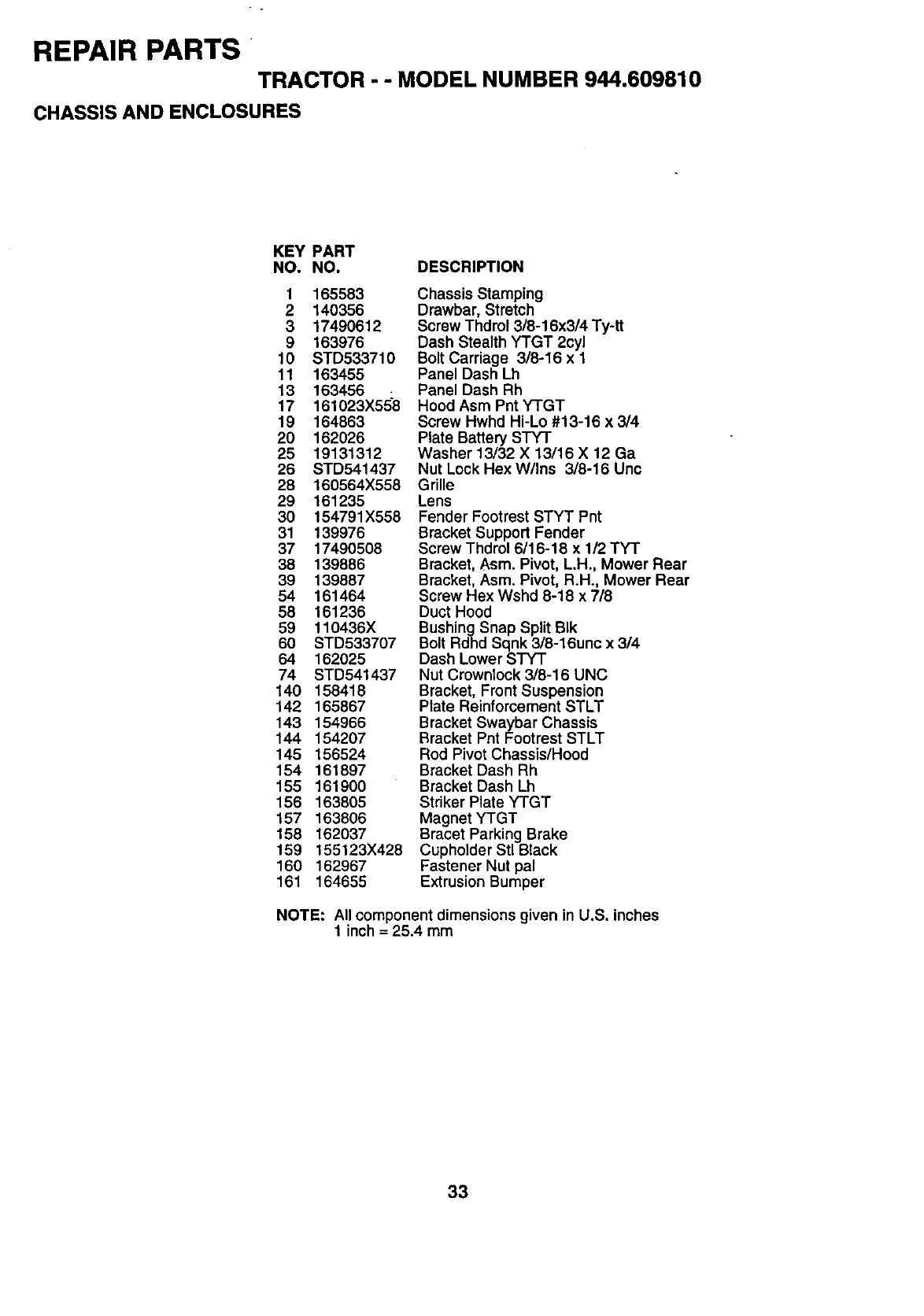
REPAIR PARTS
TRACTOR --MODEL NUMBER 944.609810
CHASSIS AND ENCLOSURES
KEY PART
NO. NO. DESCRIPTION
1165583
2 140356
3 17490612
9 163976
10 STD533710
11 163455
13 163456 :
17 161023X558
19 164863
20 162026
25 19131312
26 STD541437
28 160564X558
29 161235
30 154791X558
31 139976
37 17490508
38 139886
39 139887
54 161464
58 161236
59 110436X
60 STD533707
64 162025
74 STD541437
140 158418
142 165867
143 154966
144 154207
145 156524
154 161897
155 161900
156 163805
157 163806
158 162037
159 155123X428
160 162967
161 164655
Chassis Stamping
Drawbar, Stretch
Screw Thdrol 3/8-16x3/4 Ty-tt
Dash Stealth YTGT 2cyl
Bolt Carriage 3/8-16 x 1
Panel Dash Lh
Panel Dash Rh
Hood Asm Pnt YTGT
Screw Hwhd Hi-Lo #13-16 x 3/4
Plate Battery STY-r
Washer 13/32 X 13/16 X 12 Ga
Nut Lock Hex W/Ins 3/8-16 Unc
Grille
Lens
Fender Footrest STYT Pnt
Bracket Support Fender
Screw Thdrol 6/16-18 x 112TYT
Bracket, Asm. Pivot, L.H., Mower Rear
Bracket, Asm. Pivot, R.H+, Mower Rear
Screw Hex Wshd 8-18 x 718
Duct Hood
Bushing Snap Split BIk
Bolt Rdhd Sqnk 3/8-16une x 314
Dash Lower STYT
Nut Crownlock 3/8-16 UNC
Bracket, Front Suspension
Plate Reinforcement STLT
Bracket Swaybar Chassis
Bracket Pnt Footrest STLT
Rod Pivot Chassis/Hood
Bracket Dash Rh
Bracket Dash Lh
Striker Plate YTGT
Magnet YTGT
Bracet Parking Brake
Cupholder Stl Black
Fastener Nut pal
Extrusion Bumper
NOTE: All component dimensions given in U.S. inches
1 inch = 25.4 mm
33
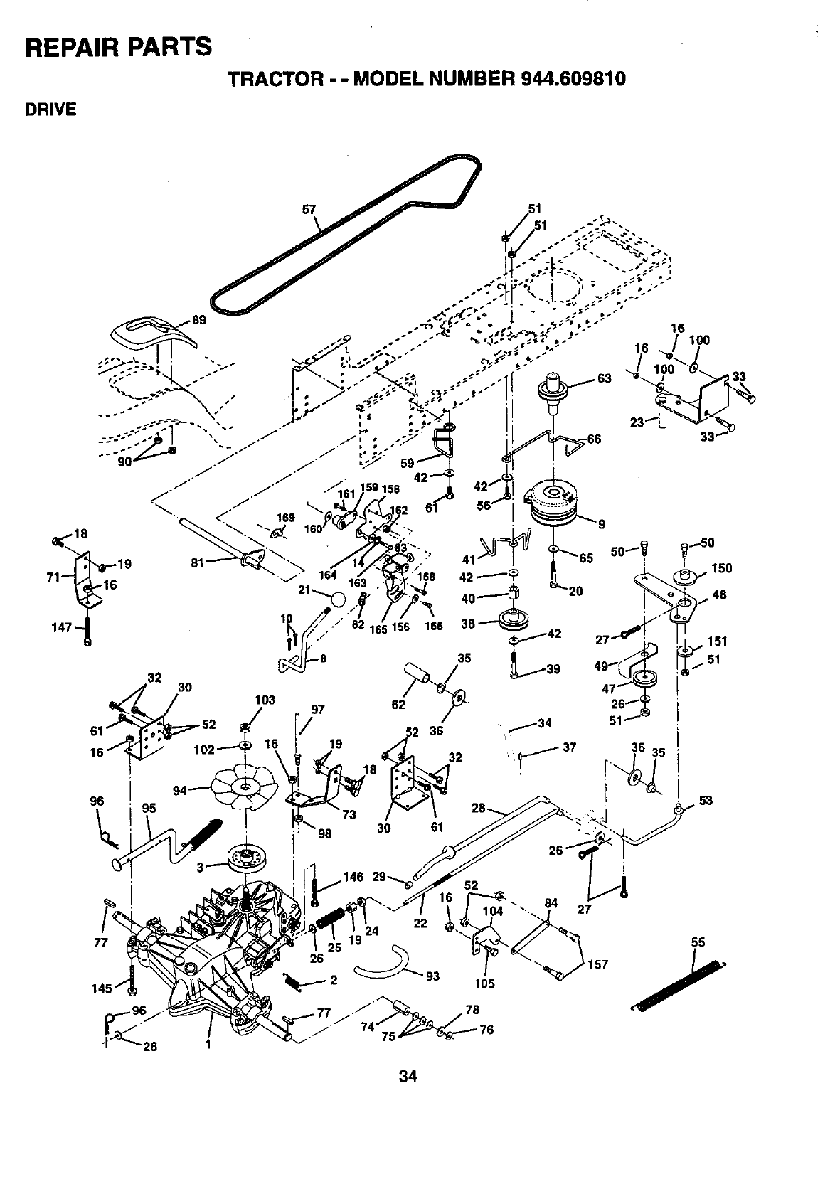
REPAIR PARTS
DRIVE
TRACTOR-- MODEL NUMBER 944.609810
34
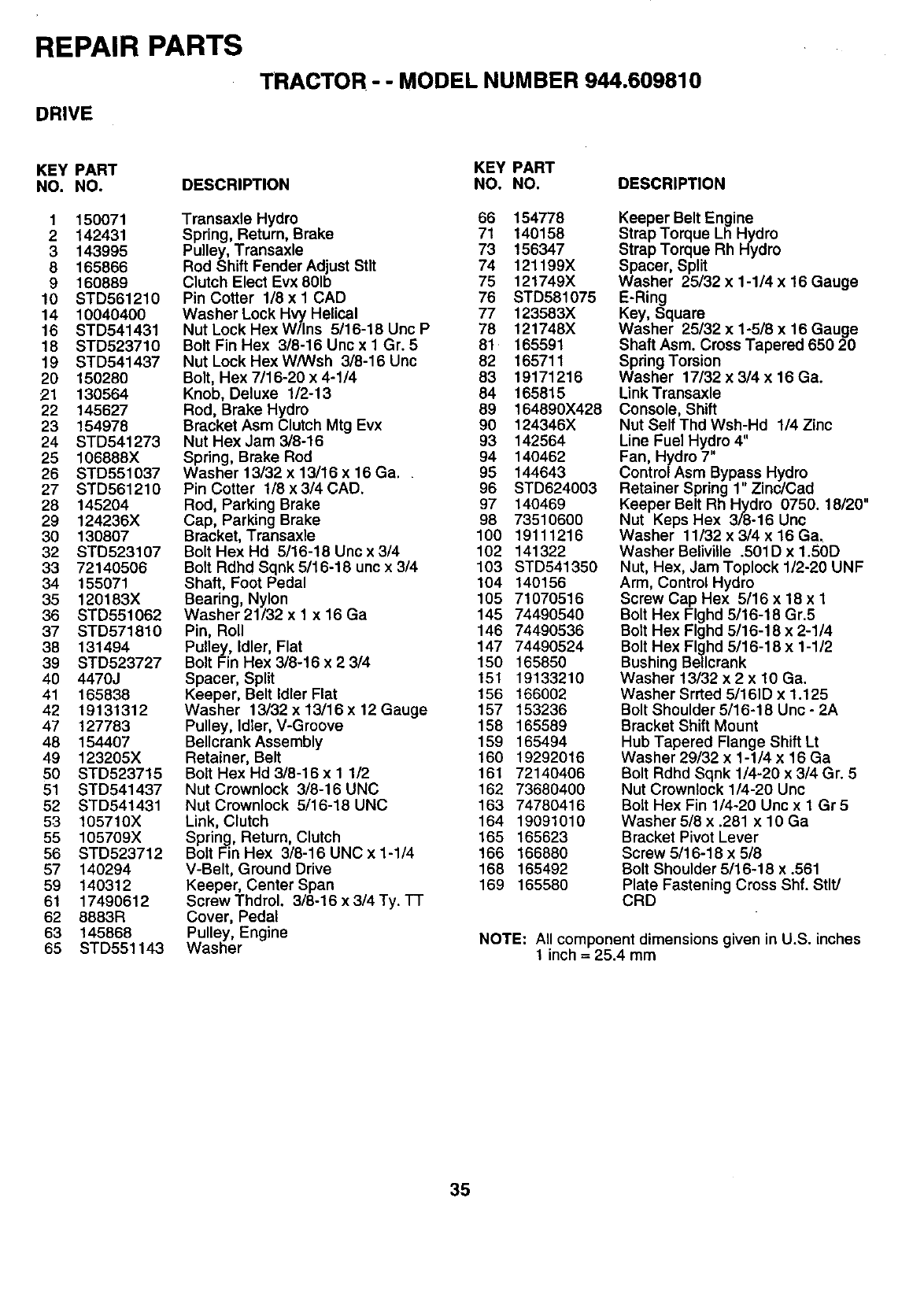
REPAIR PARTS
TRACTOR- -MODEL NUMBER 944.609810
DRIVE
KEY PART KEY PART
NO. NO. DESCRIPTION NO. NO. DESCRIPTION
1 150071
2 142431
3143995
8165866
9 160889
10 STD561210
14 10040400
16 STD541431
18 STD523710
19 STD541437
20 150280
21 130564
22 145627
23 154978
24 STD541273
25 106888X
26 STD551037
27 STD561210
28 145204
29 124236X
30 130807
32 STD523107
33 72140506
34 155071
35 120183X
36 STD551062
37 STD571810
38 131494
39 STD523727
40 4470J
41 165838
42 19131312
47 127783
48 154407
49 123205X
50 STD523715
51 STD541437
52 STD541431
53 105710X
55 105709X
56 STD523712
57 140294
59 140312
61 17490612
62 8883R
63 145868
65 STD551143
Transaxle Hydro 66 154778
Spring, Return, Brake 71 140158
Pulley, Transaxle 73 156347
Rod Shift Fender Adjust Stlt 74 121199X
Clutch Elect Evx801b 75 121749X
Pin Cotter 1/8 x 1 CAD 76 STD681075
Washer Lock Hvy Helical 77 123583X
Nut Lock Hex W/Ins 5/16-18 Unc P 78 121748X
Bolt Fin Hex 3/8-16 Uncx 1 Gr. 5 81 165591
Nut Lock Hex W/Wsh 3/8-16 Unc 82 165711
Bolt, Hex 7/16-20 x 4-1/4 83 19171216
Knob, Deluxe 112-13 84 165815
Rod, Brake Hydro 89 164890X428
Bracket Asm Clutch Mtg Evx 90 124346X
Nut Hex Jam 3/8-16 93 142564
Spring, Brake Rod 94 140462
Washer 13132 x 13/16 x 16 Ga.. 95 144643
Pin Cotter 118x 3/4 CAD. 96 STD624003
Rod, Parking Brake 97 140469
Cap, Parking Brake 98 73510600
Bracket, Transaxle 100 19111216
Bolt Hex Hd 5/16-18 Uncx3/4 102 141322
Bolt Rdhd Sqnk 5/16-18 unc x 3/4 103 STD541350
Shaft, Foot Pedal 104 140156
Bearing, Nylon 105 71070516
Washer 21/32 x 1 x 16 Ga 145 74490540
Pin, Roll 146 74490536
Pulley, Idler, Flat 147 74490524
Bolt Fin Hex 3/8-16 x 2 3/4 150 165850
Spacer, Split 151 19133210
Keeper, Belt Idler Flat 156 166002
Washer 13/32 x 13116x 12 Gauge 157 153236
Pulley, Idler, V-Groove 158 165589
Bellcrank Assembly 159 165494
Retainer, Belt 160 19292016
Bolt Hex Hd 3/8-16x 1 1/2 161 72140406
Nut Crownlock 3/8-16 UNC 162 73680400
Nut Crownlock 5/16-18 UNC 163 74780416
Link, Clutch 164 19091010
Spring, Return, Clutch 165 165623
Bolt Fin Hex 3/8-16 UNC x 1-1/4 166 166880
V-Belt, Ground Drive 168 165492
Keeper, Center Span 169 165580
Screw Thdrol. 3/8-16 x 3/4 Ty. TT
Cover, Pedal
Pulley, Engine
Washer
Keeper Belt Engine
Strap Torque Lh Hydro
Strap Torque Rh Hydro
Spacer, Split
Washer 25/32 x 1-1/4 x 16 Gauge
E-Ring
Key, Square
Washer 25/32 x 1-5/8 x 16 Gauge
Shaft Asm. Cross Tapered 650 20
Spdng Torsion
Washer 17/32 x 3/4 x 16 Ga.
Link Transaxle
Console, Shift
Nut Self Thd Wsh-Hd 1/4 Zinc
Line Fuel Hydro 4"
Fan, Hydro 7"
Control Asm Bypass Hydro
Retainer Spring 1" Zinc/Cad
Keeper Belt Rh Hydro 0750. 18/20"
Nut Keps Hex 3/8-16 Unc
Washer 11/32 x 3/4 x 16 Ga.
Washer Beliville .501D x 1.50D
Nut, Hex, Jam Toplock 1/2-20 UNF
Arm, Control Hydro
Screw Cap Hex 5/16 x 18 x 1
Bolt Hex Flghd 5/16-18 Gr.5
Bolt Hex Flghd 5/16-18 x 2-1/4
Bolt Hex Flghd 5/16-18 x 1-1/2
Bushing Bellcrank
Washer 13/32 x 2 x 10 Ga.
Washer Srrted 5/161D x 1.125
Bolt Shoulder 5/16-18 Unc - 2A
Bracket Shift Mount
Hub Tapered Flange Shift Lt
Washer 29/32 x 1-1/4 x 16 Ga
Bolt Rdhd Sqnk 1/4-20 x 3/4 Gr. 5
Nut Crownlock 1/4-20 Unc
Bolt Hex Fin 1/4-20 Unc x 1Gr 5
Washer 5/8 x .281 x 10 Ga
Bracket Pivot Lever
Screw 5/16-18 x 5/8
Bolt Shoulder 5116-18 x .561
Plate Fastening Cross Shf. StlV
CRD
NOTE: All component dimensions given in U.S. inches
1 inch = 25.4 mm
35
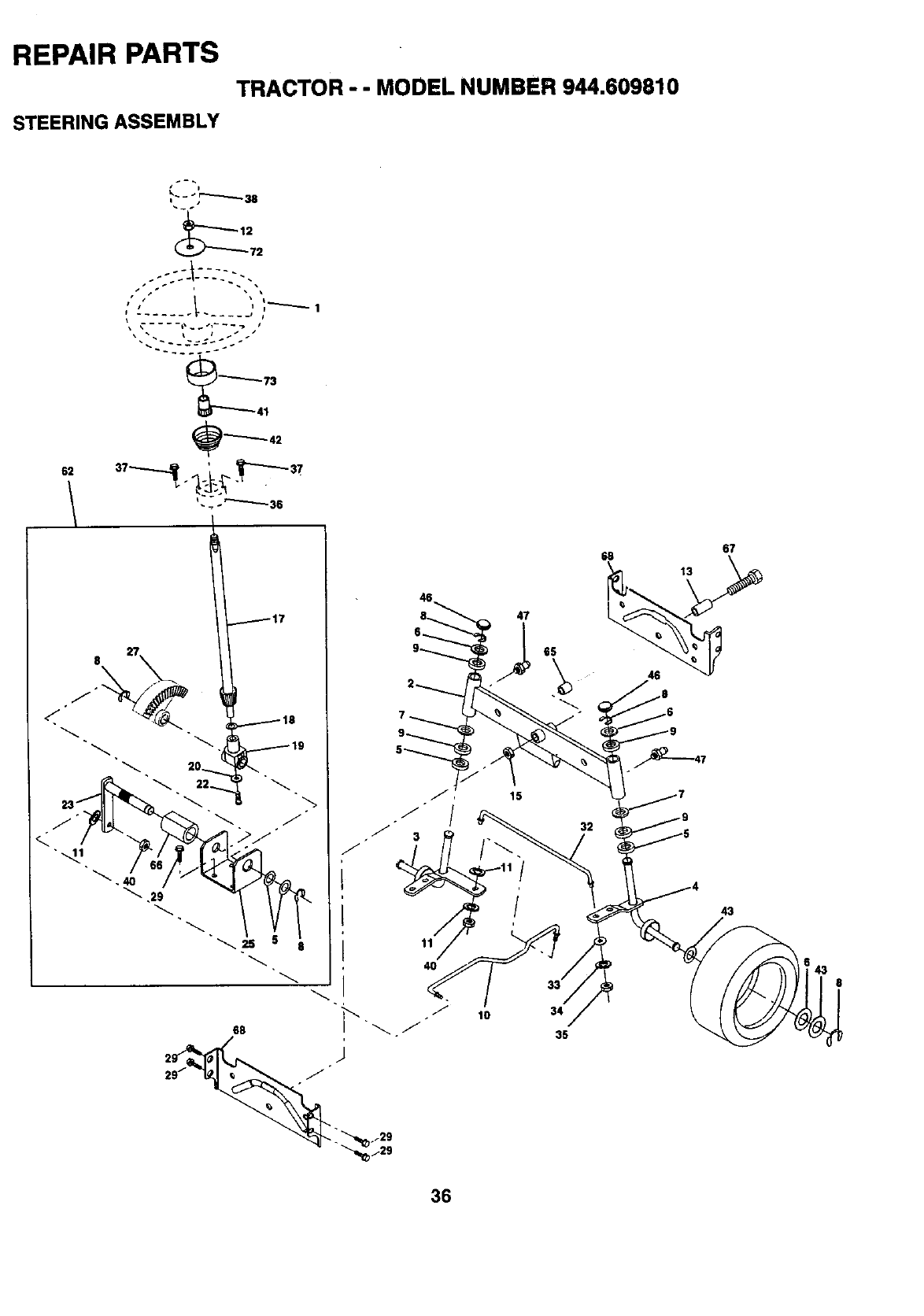
REPAIR PARTS
TRACTOR - - MODEL NUMBER 944.609810
STEERING ASSEMBLY
62
8
I p
72
, -;:::-!---:::: ..
41
17
18
" 19
67
47
32
3
11/
40
68
" 29
43
36
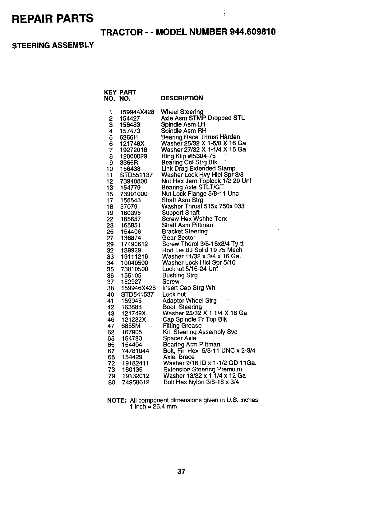
REPAIR PARTS
TRACTOR --MODEL NUMBER 944.609810
STEERING ASSEMBLY
KEY PART
NO. NO. DESCRIPTION
1 159944X428
2154427
3 156483
4157473
5 6266H
6121748X
7 19272016
8 12000029
9 3366R
10 156438
11 STD551137
12 73940800
13 154779
15 73901000
17 156543
18 57079
19 160395
22 165857
23 165851
25 154406
27 136874
29 17490612
32 139929
33 19111216
34 10040500
35 73810500
36 155105
37 152927
38 159946X428
40 STD541537
41 159945
42 163888
43 121749X
46 121232X
47 6855M
62 167905
65 154780
66 154404
67 74781044
68 154429
72 19182411
73 160135
79 19132012
80 74950612
Wheel Steering
Axle Asm STMP Dropped STL
Spindle Asm LH
Spindle Asm RH
Bearing Race Thrust Harden
Washer 25/32 X 1-5/8 X16 Ga
Washer 27/32 X 1-1/4 X 16 Ga
Ring Klip #t5304-75
Bearing Col Strg BIk
Link Drag Extended Stamp
Washer Lock Hvy Hlcl Spr 3/8
Nut Hex Jam Toplock 1/2-20 Unf
Bearing Axle STLT/GT
Nut Lock Flange 5/8-11 Unc
Shaft Asm Strg
Washer Thrust 515x 750x 033
Support Shaft
Screw Hex Wshhd Torx
Shaft Asm Pittman
Bracket Steering
Gear Sector
Screw Thdrol 3/8-16x3/4 Ty-tt
Rod Tie BJ Solid 19 75 Mech
Washer 11/32 x 3/4 x 16 Ga.
Washer Lock Hlcl Spr 5/16
Locknut 5/16-24 Unf
Bushing Strg
Screw
Insert Cap Strg Wh
Lock nut
Adaptor Wheel Strg
Boot Steering
Washer 25132 X 1 1/4 X 16 Ga
Cap Spindle Fr Top BIk
Fitting Grease
Kit, Steering Assembly Svc
Spacer Axle
Bearing Arm Pittman
Bolt, Fin Hex 518-11 UNC x 2-314
Axle, Brace
Washer 9/16 ID x 1-1/20D 11Ga.
Extension Steering Premuim
Washer 13132 x 1 1/4 x 12 Ga
Bolt Hex Nylon 3/8-16 x 3/4
NOTE: All component dimensions given in U.S. inches
1 inch = 25.4 mm
37
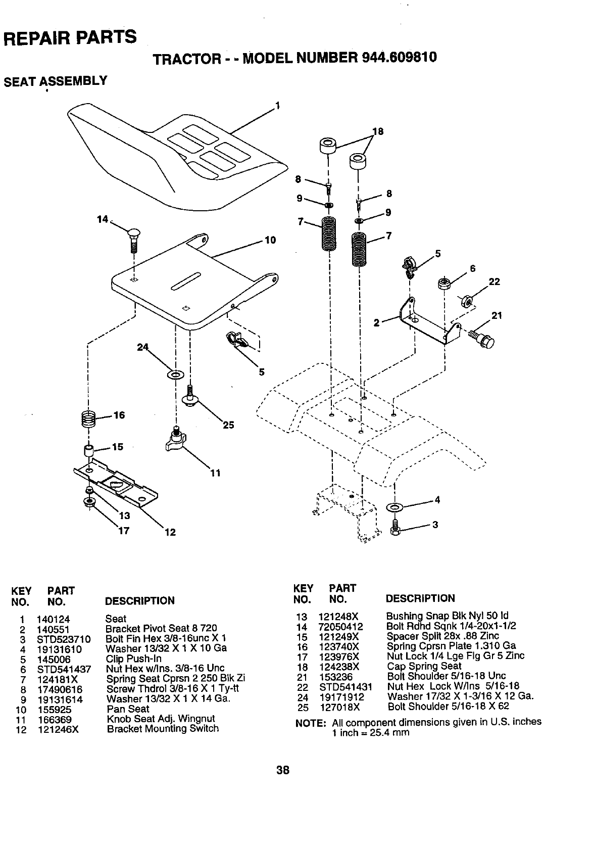
REPAIR PARTS
SEAT ASSEMBLY
TRACTOR - - MODEL NUMBER 944.609810
5
5 6
21
KEY
NO.
1
2
3
4
5
6
7
8
9
10
11
12
PART
NO.
140124
140551
STD523710
19131610
145006
STD541437
124181X
17490616
19131614
155925
166369
121246X
DESCRIPTION
Seat
Bracket Pivot Seat 8 720
Bolt Fin Hex 3/8-16unc X1
Washer 13/32 X 1 X 10 Ga
Clip Push-In
Nut Hex w/Ins. 3/8-16 Unc
Spring Seat Cprsn 2 250 Blk Zi
Screw Thdrol 3/8-16 X 1 Ty-tt
Washer 13/32 X 1 X 14 Ga,
Pan Seat
Knob Seat Adj. Wingnut
Bracket Mounting Switch
KEY PART
NO. NO. DESCRIPTION
13 121248X
14 72050412
15 121249X
16 123740X
17 123976X
18 124238X
21 153236
22 STD541431
24 19171912
25 127018X
Bushing Snap BIk Nyl 50 Id
Bolt Rdhd Sqnk 1/4-20x1-1/2
Spacer Split 28x .88 Zinc
Spring Cprsn Plate 1.310 Ga
Nut Lock 1/4 Lge Fig Gr 5 Zinc
Cap Spring Seat
Bolt Shoulder 5116-18 Unc
Nut Hex Lock W/Ins 5/16-18
Washer 17132 X 1-3/16 X 12 Ga.
Bolt Shoulder 5/16-18 X 62
NOTE: All component dimensions given in U.S. inches
1 inch = 25.4 mm
38
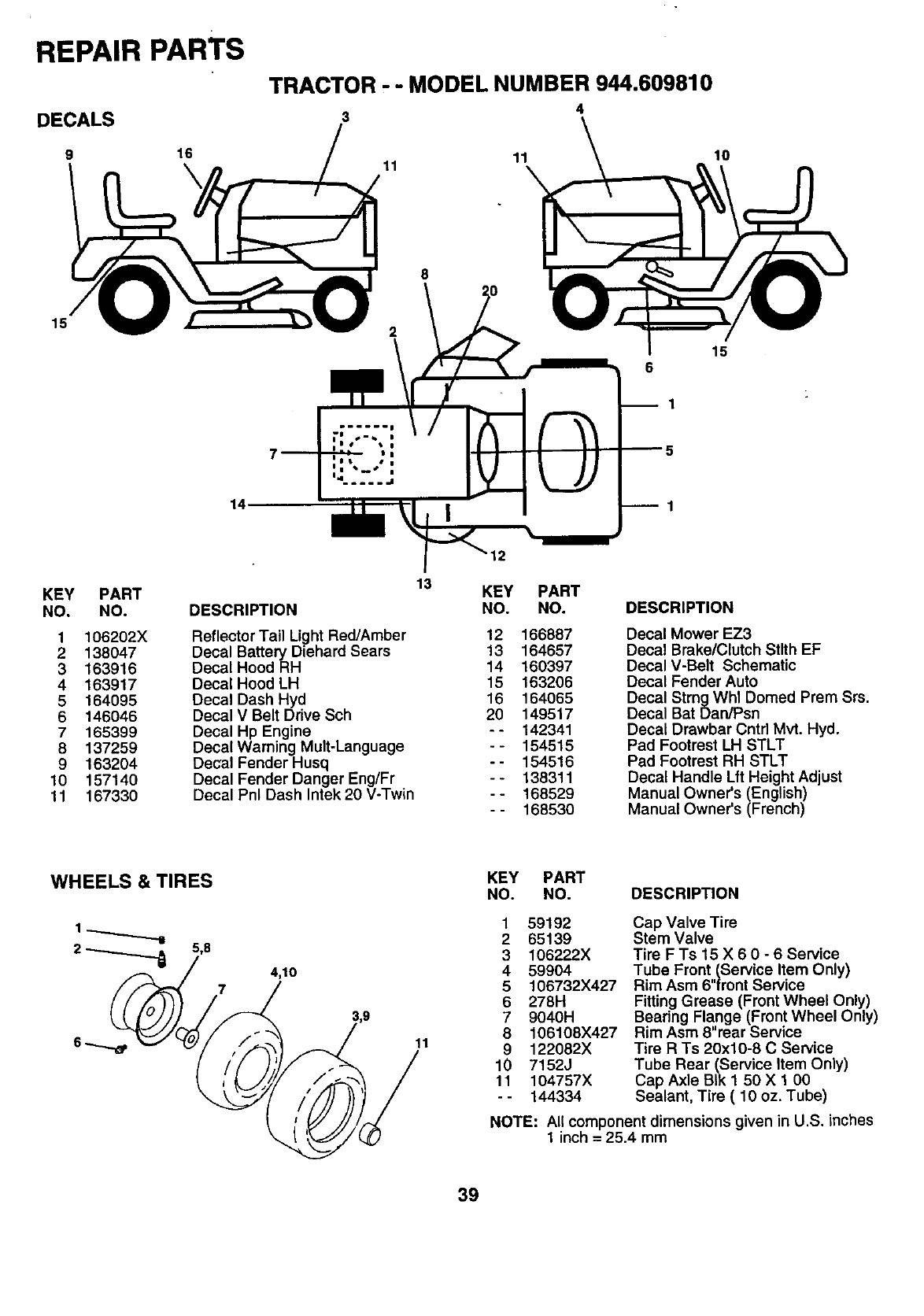
REPAIR PARTS
DECALS
9 16
\
15
TRACTOR - -MODEL NUMBER 944.609810
4
3
14,
11
2
8
11
6
10
15
1
KEY PART
NO. NO.
1106202X
2138047
3163916
4163917
5 164095
6146046
7 165399
8 137259
9 163204
10 157140
11 167330
DESCRIPTION
Reflector Tail Light Red/Amber
Decal Battery Diehard Sears
Decal Hood RH
Decal Hood LH
Decal Dash Hyd
Decal V Belt Ddve Sch
Decal Hp Engine
Decal Warning Mult-Language
Decal Fender Husq
Decal Fender Danger Eng/Fr
Decal Pnl Dash Intek 20 V-Twin
13 KEY PART
NO. NO.
12 166887
13 164657
14 160397
15 163206
16 164065
20 149517
-- 142341
-- 154515
-- 154516
-- 138311
-- 168529
-- 168530
DESCRIPTION
Decal Mower EZ3
Decal Brake/Clutch Stlth EF
Decal V-Belt Schematic
Decal Fender Auto
Decal StrngWhl Domed Prem Srs.
Decal Bat Dan/Psn
Decal Drawbar Cntd Mvt. Hyd.
Pad Footrest LH STLT
Pad Footrest RH STLT
Decal Handle Lft Height Adjust
Manual Owner's (English)
Manual Owner's (French)
WHEELS & TIRES
2_5,8 4,10
11
KEY PART
NO. NO. DESCRIPTION
1 59192
2 65139
3 106222X
4 59904
5 106732X427
6 278H
7 9040H
8 106108X427
9 122082X
10 7152J
11 104757X
-- 144334
Cap Valve Tire
Stem Valve
Tire FTs 15 X 6 0-6Service
Tube Front.(Service Item Only)
Rim Asm 6 front Service
Fitting Grease (Front Wheel Only)
Bearing Flange (Front Wheel Only)
Rim Asm 8"rear Service
Tire R Ts 20x10-8 C Service
Tube Rear (Service Item Only)
Cap Axle BIk 1 50 X 1 00
Sealant, Tire ( 10 oz. Tube)
NOTE: All component dimensions given in U.S. inches
1 inch = 25.4 mm
39
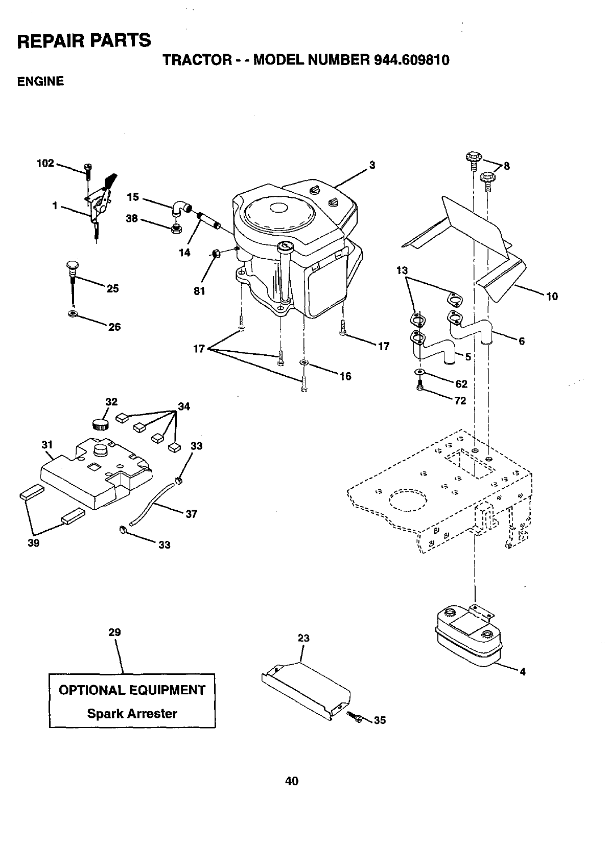
REPAIR PARTS
TRACTOR - - MODEL NUMBER 944.609810
ENGINE
14
31
81
I
39
32 34
33
37
29
\
I OPTIONAL EQUIPMENT I
Spark Arrester
13
"17
I
23
/
10
4O
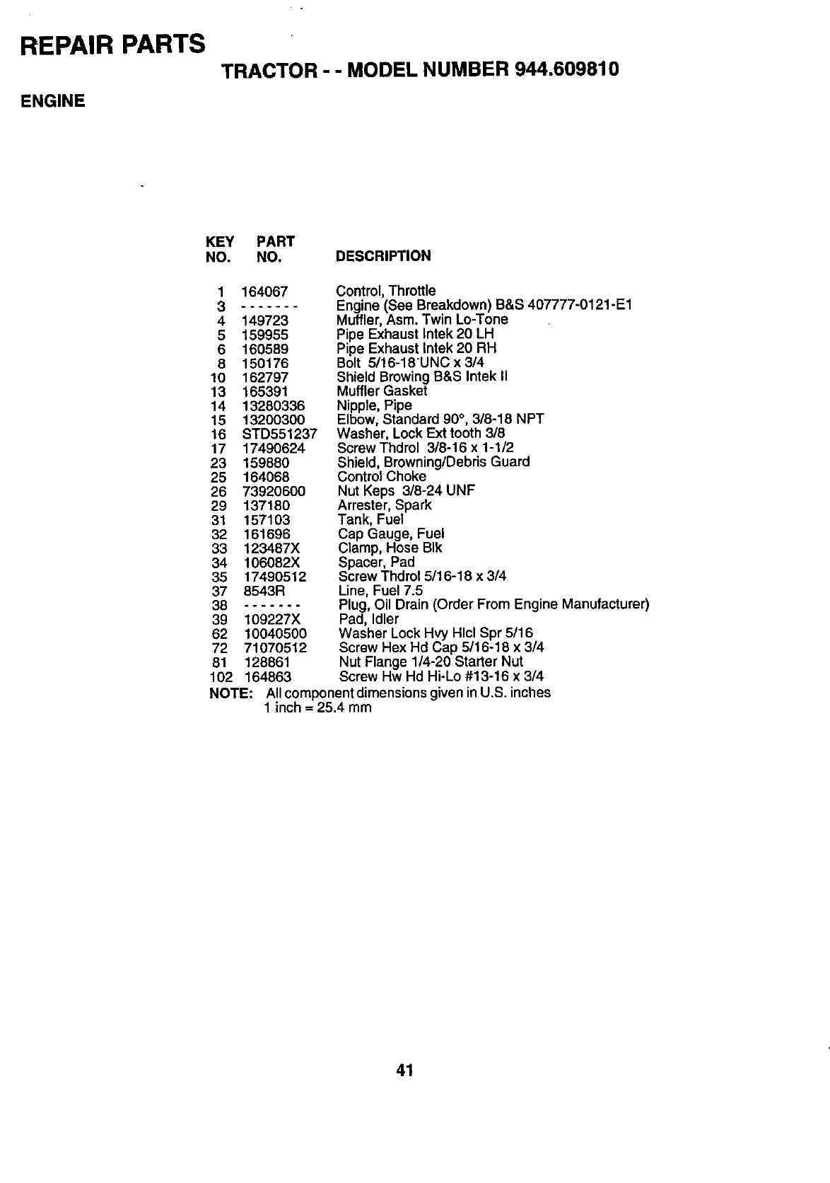
REPAIR PARTS
TRACTOR --MODEL NUMBER 944,609810
ENGINE
KEY PART
NO. NO. DESCRIPTION
1 164067
.......
4 149723
5 159955
6 160589
8 150176
10 162797
13 165391
14 13280336
15 13200300
16 STD551237
17 17490624
23 159880
25 164068
26 73920600
29 137180
31 157103
32 161696
33 123487X
34 106082X
35 17490512
37 8543R
38 .......
39 109227X
62 10040500
72 71070512
81 128861
Control, Throttle
Engine (See Breakdown) B&S 407777-0121-E1
Muffler, Asm. Twin Lo-Tone
Pipe Exhaust Intek 20 LH
Pipe Exhaust Intek 20 RH
Bolt 5/16-18UNC x 3/4
Shield Browing B&S Intek II
Muffler Gasket
Nipple, Pipe
Elbow, Standard 90°, 3/8-18 NPT
Washer, Lock Ext tooth 3/8
Screw Thdrol 3/8-16 x 1-1/2
Shield, Browning/Debris Guard
Control Choke
Nut Keps 3/8-24 UNF
Arrester, Spark
Tank, Fuel
Cap Gauge, Fuel
Clamp, Hose BIk
Spacer, Pad
Screw Thdrol 5/16-18 x 314
Line, Fuel 7.5
Plug, Oil Drain (Order From Engine Manufacturer)
Pad, Idler
Washer Lock Hvy Hlcl Spr 5/16
Screw Hex Hd Cap 5/16-18 x 3/4
Nut Flange 1/4-20 Starter Nut
102 164863 Screw Hw Hd Hi-Lo #13-16 x 3/4
NOTE: All component dimensions given in U.S. inches
1 inch = 25.4 mm
41
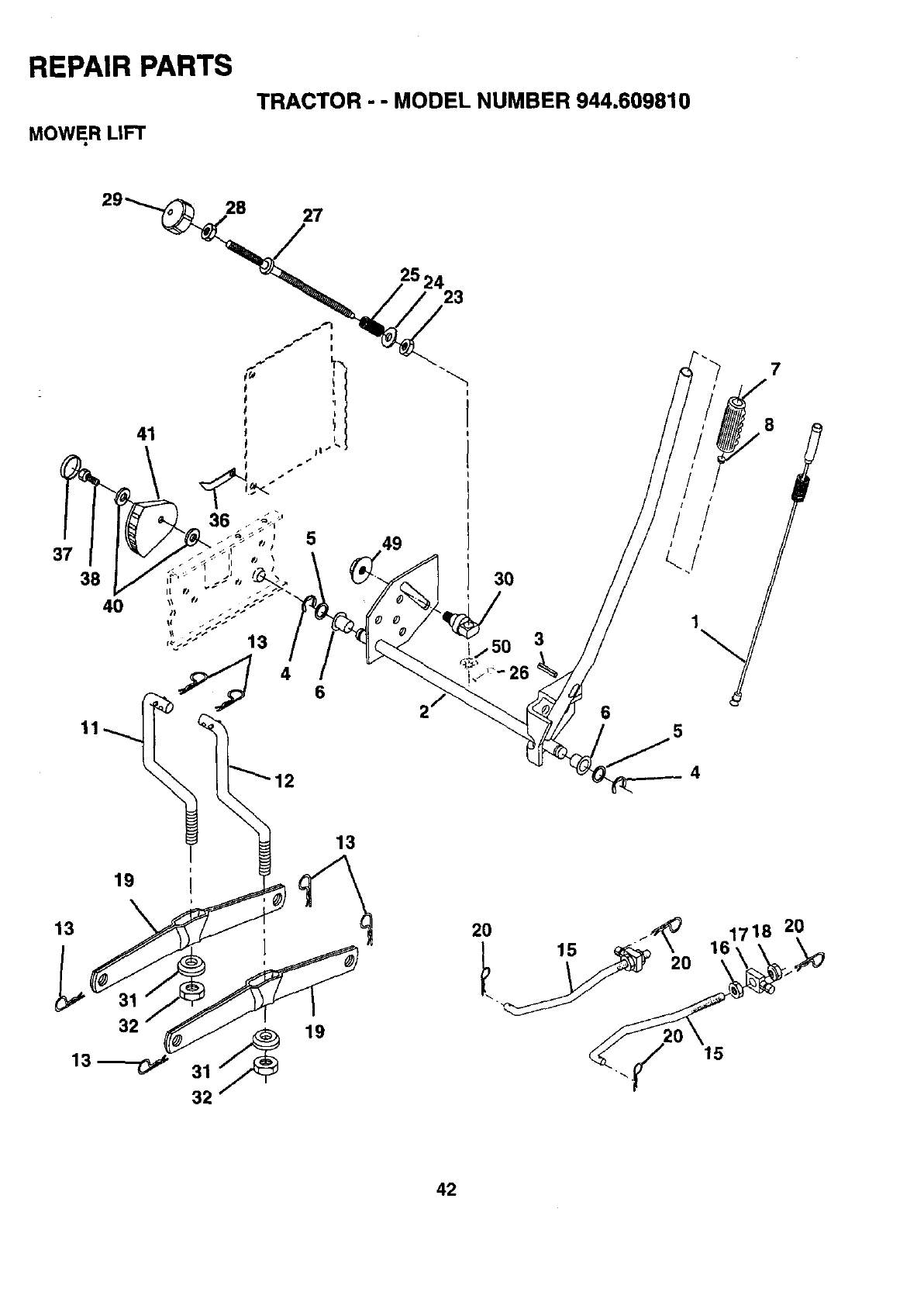
REPAIR PARTS
MOWER LIFT
TRACTOR - -MODEL NUMBER 944.609810
28 27
25 24 23
11 6
/
5
7
4
19
13
13
32
32
19
2O
15 2O
1718 20
16
15
42
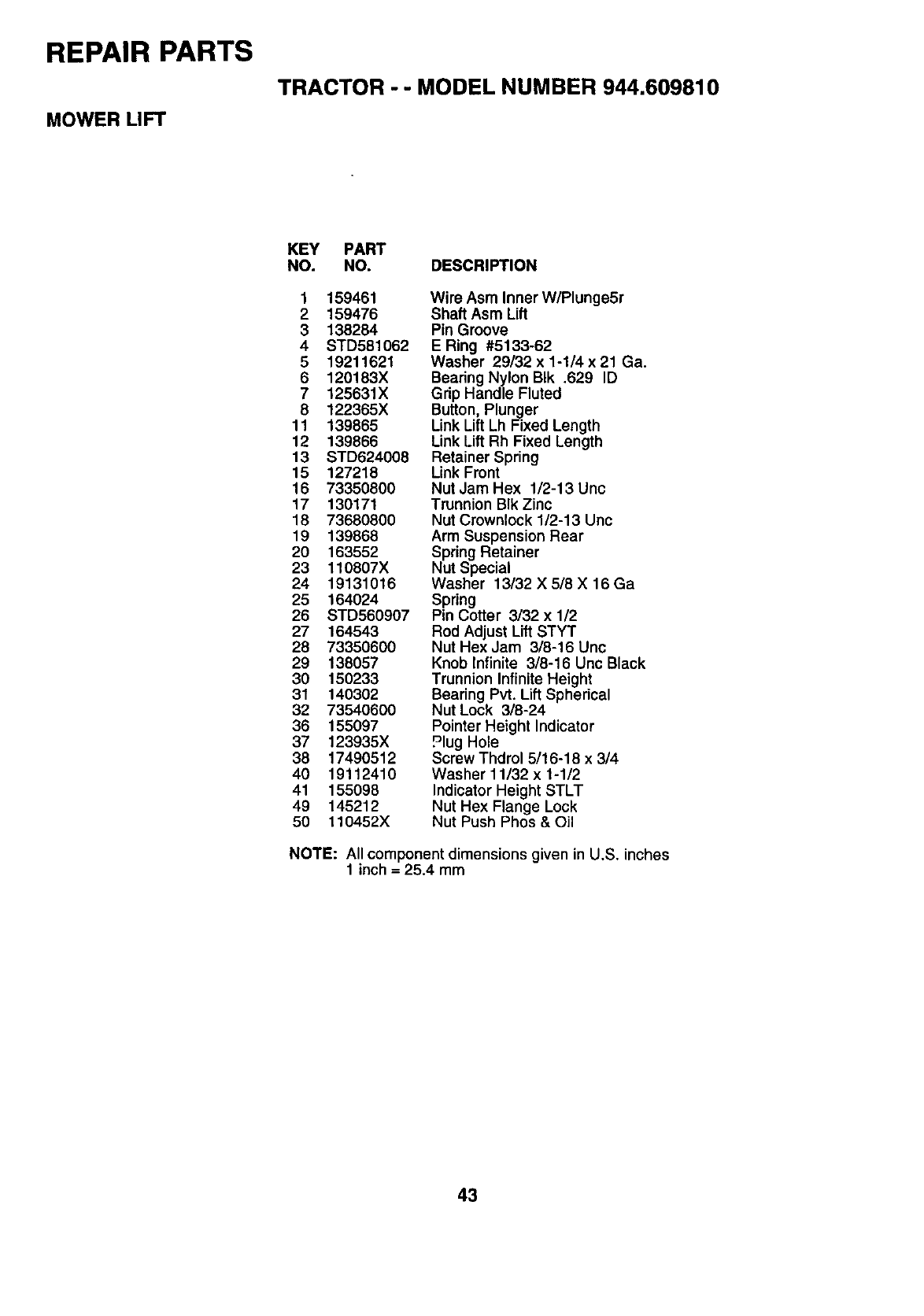
REPAIR PARTS
TRACTOR - - MODEL NUMBER 944.609810
MOWER LIFT
KEY PART
NO. NO. DESCRIPTION
1 159461
2159476
3138284
4 STD581062
5 19211621
6 120183X
7 125631X
8 122365X
11 139865
12 139866
13 STD624008
15 127218
16 73350800
17 130171
18 73680800
19 139868
20 163552
23 110807X
24 19131016
25 164024
26 STD560907
27 164543
28 73350600
29 138057
30 150233
31 140302
32 73540600
36 155097
37 123935X
38 17490512
40 19112410
41 155098
49 145212
50 110452X
Wire Asm Inner W/Plunge5r
Shaft Asm Lift
Pin Groove
E Ring #5133-62
Washer 29/32 x 1-1/4 x 21 Ga.
Beadng Nylon BIk .629 ID
Gdp Handle Fluted
Button, Plunger
Link Lift Lh Fixed Length
Link Lift Rh Fixed Length
Retainer Spring
Link Front
Nut Jam Hex 1/2-13 Unc
Trunnion BIk Zinc
Nut Crownlock 1/2-13 Unc
Arm Suspension Rear
Spring Retainer
Nut Special
Washer 13/32 X 5/8 X 16 Ga
Spring
Pin Cotter 3/32 x 1/2
Rod Adjust Lift STYT
Nut Hex Jam 3/8-16 Unc
Knob Infinite 3/8-16 Unc Black
Trunnion Infinite Height
Bearing Pvt. Lift Spherical
Nut Lock 3/8-24
Pointer Height Indicator
Plug Hole
Screw Thdrol 5/16-18 x 314
Washer 11132 x 1-112
Indicator Height STLT
Nut Hex Flange Lock
Nut Push Phos & Oil
NOTE: All component dimensions given in U.S. inches
1inch = 25.4 mm
43
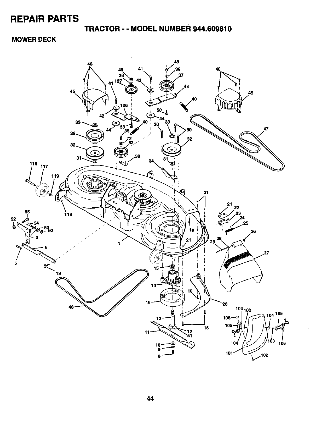
REPAIR PARTS
TRACTOR - - MODEL NUMBER 944.609810
MOWER DECK
116 117
119
46
45\
49
I
!31_
47
1
21
21
3
24
25
26
,/
18
44
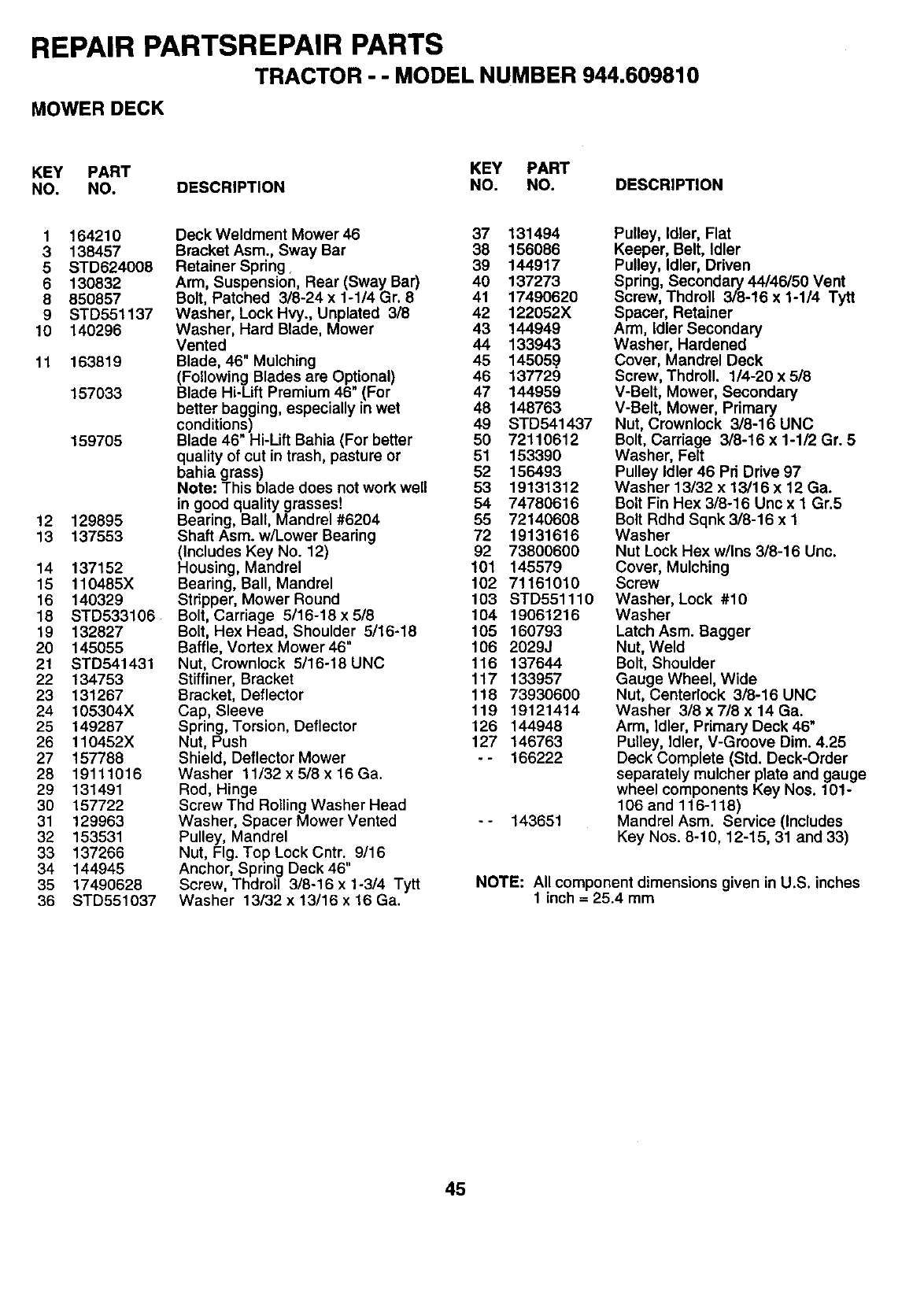
REPAIR PARTSREPAIR PARTS
TRACTOR - - MODEL NUMBER 944.609810
MOWER DECK
KEY PART KEY PART
NO. NO. DESCRIPTION NO. NO. DESCRIPTION
1 164210
3138457
5 STD624008
6130832
8 850857
9STD551137
10 140296
11 163819
157033
159705
12 129895
13 137553
14 137152
15 110485X
16 140329
18 STD533106
19 132827
20 145055
21 STD541431
22 134753
23 131267
24 105304X
25 149287
26 110452X
27 157788
28 19111016
29 131491
30 157722
31 129963
32 153531
33 137266
34 144945
35 17490628
36 STD551037
Deck Weldment Mower 46 37 131494
Bracket Asm., Sway Bar 38 156086
Retainer Spring. 39 144917
Arm, Suspension, Rear (Sway Bar) 40 137273
Bolt, Patched 3/8-24 x 1-1/4 Gr. 8 41 17490620
Washer, Lock Hvy., Unplated 3/8 42 122052X
Washer, Hard Blade, Mower 43 144949
Vented 44 133943
Blade, 46" Mulching 45 14505.9
(Following Blades are Op!ional) 46 137729
Blade Hi-Lift Premium 46 (For 47 144959
better bagging, especially in wet 48 148763
conditions) 49 STD541437
Blade 46" Hi-Lift Bahia (For better 50 72110612
quality of cut in trash, pasture or 51 163390
bahia grass) 52 156493
Note: This blade does not work well 53 19131312
in good quality grasses! 54 74780616
Bearing, Ball, Mandrel #6204 55 72140608
Shaft Asm. w/Lower Bearing 72 19131616
(Includes Key No. 12) 92 73800600
Housing, Mandrel 101 145579
Bearing, Ball, Mandrel 102 71161010
Stripper, Mower Round 103 STD551110
Bolt, Carriage 5/16-18 x 5/8 104 19061216
Bolt, Hex Head, Shoulder 5/16-18 105 160793
Baffle, Vortex Mower 46" 106 2029J
Nut, Crownlock 5/16-18 UNC 116 137644
Stiffiner, Bracket 117 133957
Bracket, Deflector 118 73930600
Cap, Sleeve 119 19121414
Spring, Torsion, Deflector 126 144948
Nut, Push 127 146763
Shield, Deflector Mower -- 166222
Washer 11/32 x 5/8 x 16 Ga.
Rod, Hinge
Screw Thd Rolling Washer Head
Washer, Spacer Mower Vented - - 143651
Pulley, Mandrel
Nut, Fig. Top Lock Cntr. 9/16
Anchor, Spring Deck 46"
Screw, Thdrol 3/8-16 x 1-3/4 Tytt
Washer 13/32 x 13/16 x 16 Ga.
Pulley, Idler, Flat
Keeper, Belt, Idler
Pulley, Idler, Driven
Spring, Secondary 44/46/56 Vent
Screw, Thdroll 3/8-16 x 1-1/4 Tytt
Spacer, Retainer
Arm, Idler Secondary
Washer, Hardened
Cover, Mandrel Deck
Screw, Thdroll. 1/4-20 x 5/8
V-Belt, Mower, Secondary
V-Belt, Mower, Primary
Nut, Crownlock 3/8-16 UNC
Bolt, Carriage 3/8-16 x 1-1/2 Gr. 5
Washer, Felt
Pulley Idler 46 Pri Drive 97
Washer 13/32 x 13/16 x 12 Ga.
Bolt Fin Hex 3/8-16 Unc x I Gr.5
Bolt Rdhd Sqnk 3/8-16 x 1
Washer
Nut Lock Hex w/Ins 3/8-16 Unc.
Cover, Mulching
Screw
Washer, Lock #10
Washer
Latch Asm. Bagger
Nut, Weld
Bolt, Shoulder
Gauge Wheel, Wide
Nut, Centerlock 3/8-16 UNC
Washer 3/8 x 7/8 x 14 Ga.
Arm, Idler, Primary Deck 46"
Pulley, Idler, V-Groove Dim. 4.25
Deck Complete (Std. Deck-Order
separately mulcher plate and gauge
wheel components Key Nos. 101-
106 and 116-118)
Mandrel Asm. Service (Includes
Key Nos. 8-10, 12-15, 31 and 33)
NOTE: All component dimensions given in U°S. inches
1 inch = 25.4 mm
45
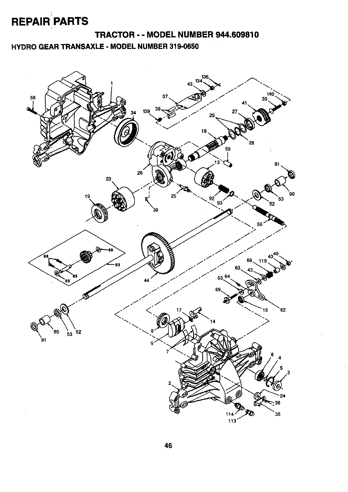
REPAIR PARTS
TRACTOR -- MODEL NUMBER 944.609810
HYDRO GEAR TRANSAXLE -MODEL NUMBER 319-0650
58
34
26
23
91
19
9O
17
4
90
35
1
46
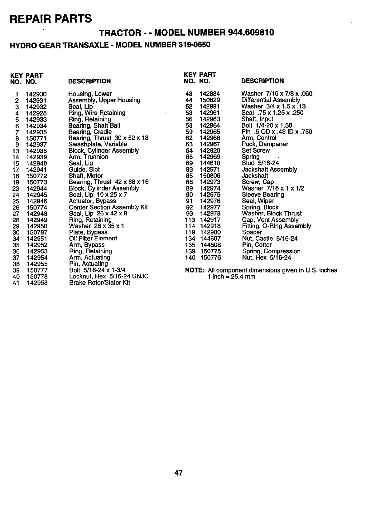
REPAIR PARTS
TRACTOR - - MODEL NUMBER 944.609810
HYDRO GEAR TRANSAXLE -MODEL NUMBER319-0650
KEY PART KEY PART
NO. NO. DESCRIPTION NO. NO. DESCRIPTION
1 142930 Housing, Lower 43 142884
2 142931 Assembly, Upper Housing 44 150829
3 142932 Seal, Lip 52 142991
4 142928 Ring, Wire Retaining 53 142961
5 142933 Ring, Retaining 56 142963
6 142934 Bearing, Shaft Ball 58 142964
7 142935 Bearing, Cradle 59 142965
8 150771 Bearing, Thrust 30x52 x 13 62 142966
9 142937 Swashplate, Variable 63 142967
13 142938 Block, Cylinder Assembly 64 142920
14 142939 Arm, Trunnion 68 142969
15 142940 Seal, Lip 69 144610
17 142941 Guide, Slot 83 142971
18 150772 Shaft, Motor 85 150806
19 150773 Bearing, Thrust 42 x 68 x 16 88 142973
23 142944 Block, Cylinder Assembly 89 142974
24 142945 Seal, Lip 10 x 25 x 7 90 142975
25 142946 Actuator, Bypass 91 142976
26 150774 Center Section Assembly Kit 92 142977
27 142948 Seal, Lip 26 x 42 x 8 93 142978
28 142949 Ring, Retaining 113 142917
29 142950 Washer 26x35x1 114 142918
30 150787 Plate, Bypass 119 142980
34 142951 Oil Filter Element 134 144607
35 142952 Arm, Bypass 135 144608
36 142953 Ring, Retaining 139 150775
37 142954 Arm, Actuating 140 150776
38 142955 Pin, Actuating
39 150777 Bolt 5/16-24 x 1-3/4
40 150778 Locknut, Hex 5/16-24 UNJC
41 142958 Brake Rotor/Stator Kit
Washer 7/16 x 7/8 x .060
Differential Assembly
Washer 314x 1.5 x .13
Seal .75 x 1.25 x .250
Shaft, Input
Bolt 1/4-20 x 1.38
Pin .5 GD x .43 ID x .750
Arm, Control
Puck, Dampener
Set Screw
Spring
Stud 5/16-24
Jackshaft Assembly
Jackshaft
Screw, Cap
Washer 7/16 x I x 1/2
Sleeve Bearing
Seal, Wiper
Spring, Block
Washer, Block Thrust
Cap, Vent Assembly
Fitting, O-Ring Assembly
Spacer
Nut, Castle 5/16-24
Pin, Cotter
Spring, Compression
Nut, Hex 5/16-24
NOTE: All component dimensions given in U.S. inches
1 inch = 25.4 mm
47
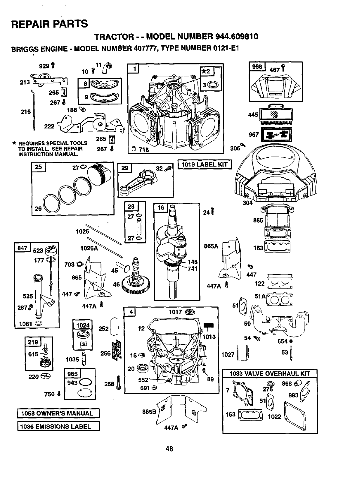
REPAIR PARTS
TRACTOR -- MODEL NUMBER 944.609810
BRIGGS ENGINE -MODEL NUMBER 407777, TYPE NUMBER 0121-E1
929t lO yl1_
267
216 188
222 @_
"k REQUIRES SPECIAL TOOLS 265
TO INSTALL. SEE REPAIR 267
INSTRUCTION MANUAL, 305 _
967
1081
220
750
865 _46 _
447 _
_7A
A
252L
!
I1019 LABEL KIT_
1058 OWNER'S MANUAL J
11036 EMISSIONS LABEL I
148
741
41 lO17
691
447A_
304
24_ 8551 _
865A_ , 163_
447A
447
51A_
51_550_
54 _654 O
1027L-- _53 1
1033 VALVE OVERHAUL KIT
%._ 51_'_ 883_
48
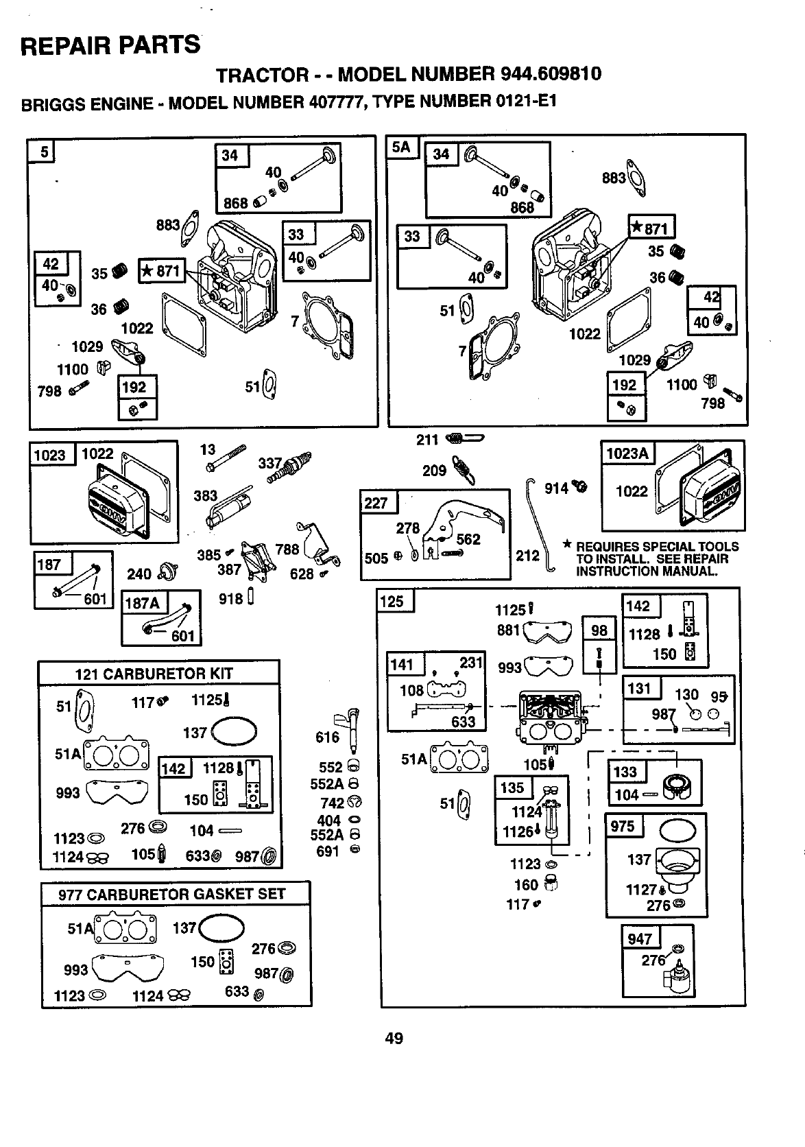
REPAIR PARTS
TRACTOR - - MODEL NUMBER 944,609810
BRIGGS ENGINE -MODEL NUMBER 407777, TYPE NUMBER 0121-E1
11o°o
798 _192 61_
240
41 40
868 @s_
386-
387 _628 _"
918 0
5AI 341t_ I -
_//;e"]_ 10221 .._ .•
7_ 102-_,_
19..j_211_• _
_@ 798_
121 CARBURETOR KIT
51 _117_ 11251
14_ 11281mI
276 _104 _=
1123_
1124_ 105_ 633@ 987@
977 CARBURETOR GASKET SET
,3,0
993_ 150_ 276 _)
987@
1123 _1124 _633 @
211
209
278
\_r REQUIRES SPECIALTOOLS
1505 _ @ I_Jam 1212_ TO INSTALL. SEE REPAIR
| I INSTRUCTION MANUAL.
1251 11251 1142I r] I
552 _51A_
552A
742 _61
404
552A
691
1123_ 137_
160_ 1127_J
117 _276_
49
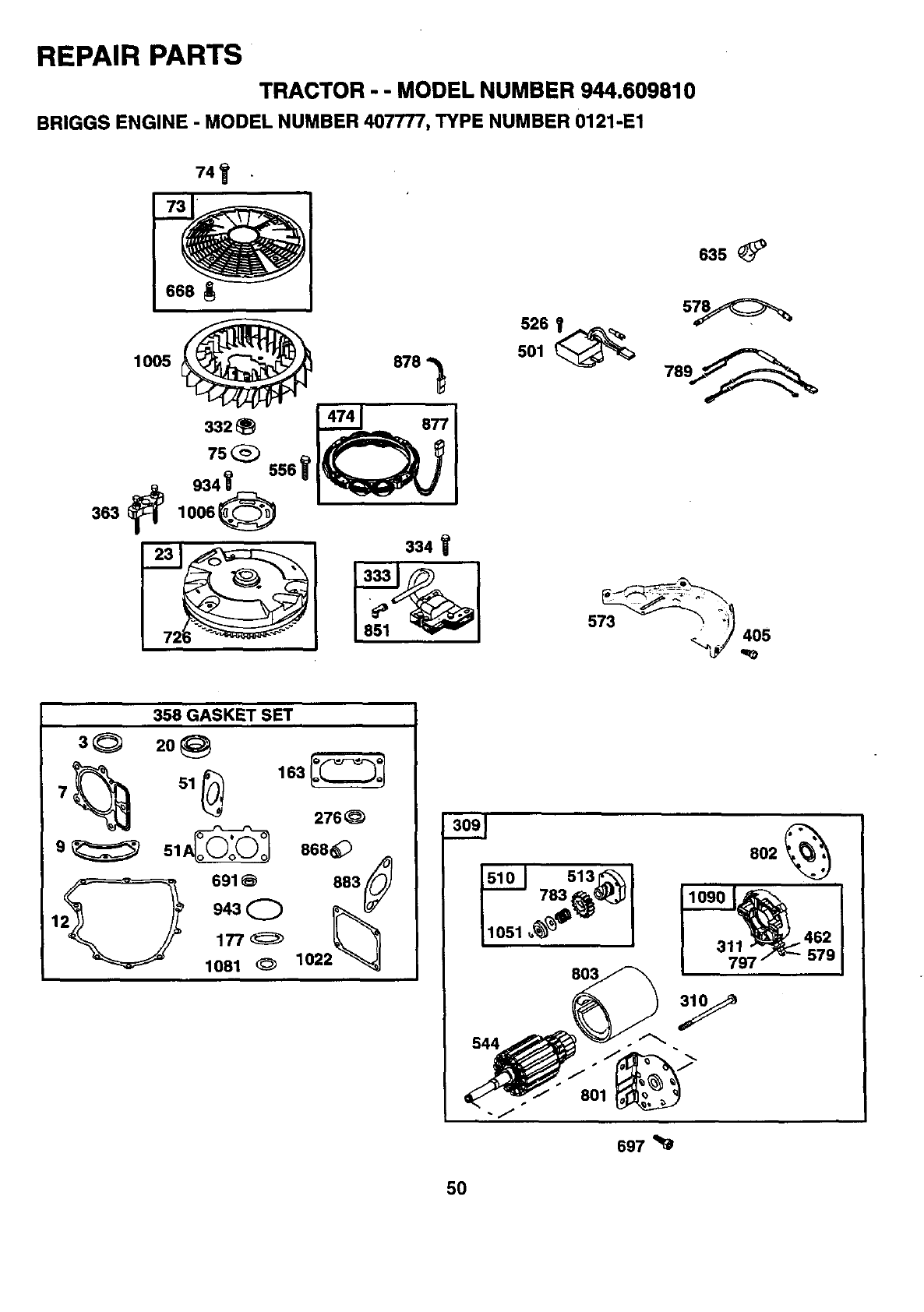
REPAIR PARTS
TRACTOR - -MODEL NUMBER 944.609810
BRIGGS ENGINE -MODEL NUMBER 407777, TYPE NUMBER 0121-E1
74'_
63s
6_
573 _ _
_j_6
358 GASKET SET
3Q 2o_
276
9_ Sl_ 666@ _
/oJ
691_ 683(_J
1_ )_ o4_
697
5O
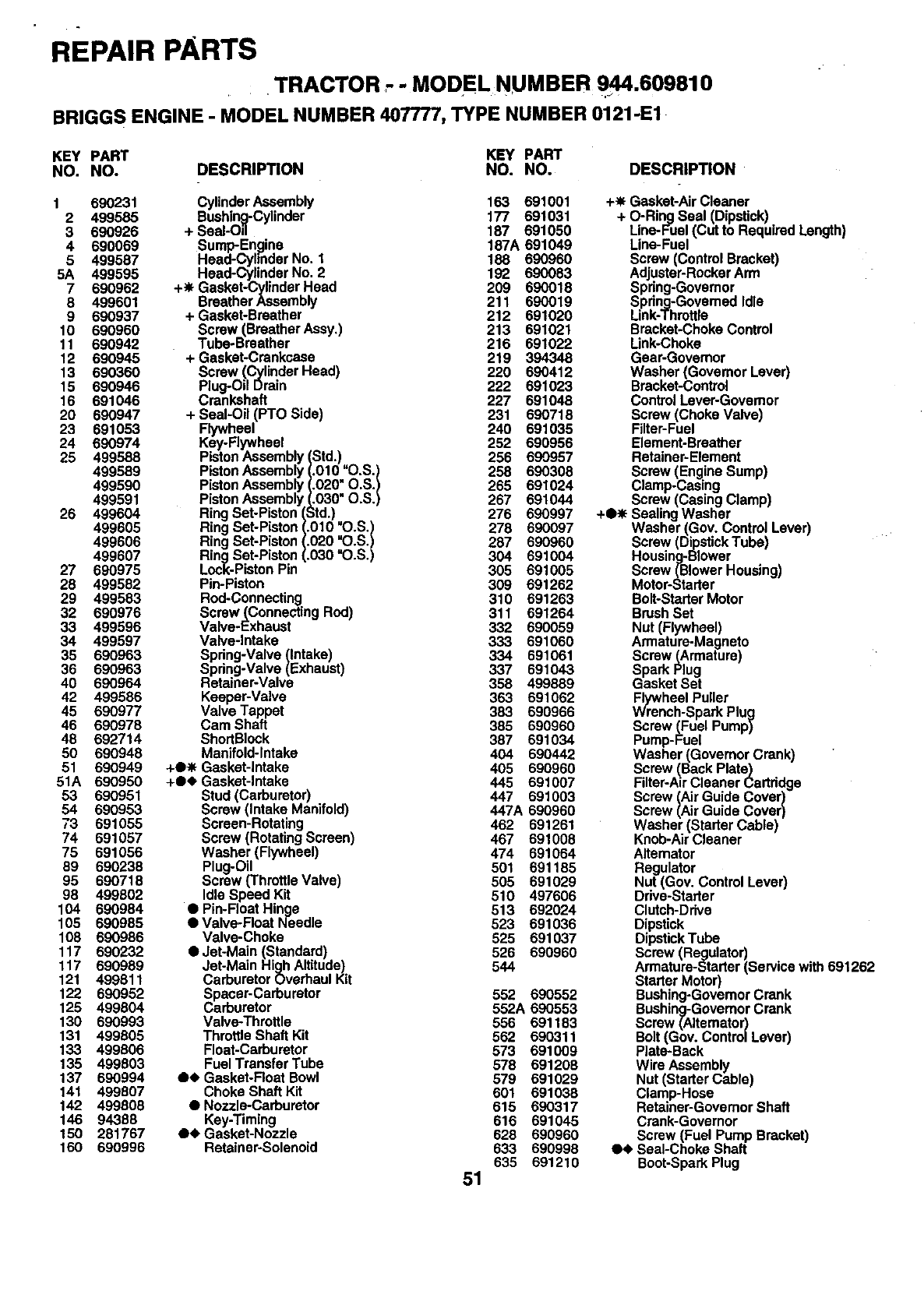
REPAIR PARTS
TRACTOR " " MODEL NUMBER 944.609810
BRIGGS ENGINE -MODEL NUMBER 407777, TYPE NUMBER 0121-E1
KEY PART KEY PART
NO. NO. DESCRIPTION NO. NO. DESCRIPTION
1 690231
2 499585
3 690926
4 690069
5 499587
5A 499595
7 690962
8 499601
9 690937
10 690960
11 690942
12 690945
13 690360
15 690946
16 691046
20 690947
23 691053
24 690974
25 499588
499589
499590
499591
26 499604
499605
499606
499607
27 690975
28 499582
29 499583
32 690976
33 499596
34 499597
35 690963
36 690963
40 690964
42 499586
45 690977
46 690978
48 692714
5O 690948
51 690949
51A 690950
53 690951
54 690953
73 691055
74 691057
75 691056
89 690238
95 690718
98 499802
104 690984
105 690985
108 690986
117 690232
117 690989
121 499811
122 690952
125 499804
130 690993
131 499605
133 499806
135 499603
137 690994
141 499607
142 499808
146 94368
150 281767
160 690996
CylinderAssembly
Bushing-Cylinder
+ Seal-Oil
Sump-En_line
Head-CylinderNo. 1
Head-CylinderNo. 2
+_ Gasket-CylinderHead
BreatherAssembly
+ Gasket-Breather
Screw (BreatherAssy.)
Tube-Breather
+ Gasket-CrenkGase
Screw (CylinderHead)
Plug-OilDrain
Crankshaft
+ Seal-Oil (PTO Side)
Flywheel
Key-Rywheal
PistonAssembl Std.)
PistonAssembl 010 =O.S.)
PistonAssembl 020=O.S.)
PistonAssembl 030" O.S.)
RingSet-Piston td.)
RingSet-Piston )10 "O.S.)
RingSet-Piston '.020 =O.S.)
RingSet-Piston =.030"O.S.)
Lock-PistonPin
Pin-Piston
Rod-Connecting
Screw (ConnectingRod)
Valve-Exhaust
Valve-Intake
Spring-Valve(Intake)
Spring-Valve(Exhaust)
Retainer-Valve
Keeper-Valve
Valve Tappet
Cam Shaft
ShortBIock
Manifold-Intake
+O_ Gasket-Intake
+Oe Gasket-Intake
Stud(Carburetor)
Screw(Intake Manifold)
Screen-Rotating
Screw (RotatingScreen)
Washer (Flywheel)
Plug-Oil
Screw (ThrottleValve)
IdleSpeed Kit
• Pin-FloatHinge
• Valve-Roat Needle
Valve-Choke
•Jet-Main (Standard)
Jet-Main HighAltitude)
CarburetorOverhaulKit
Spacer-Carburetor
Carburetor
Valve-Throttle
ThrottleShaft Kit
Float-Carburetor
FuelTransferTube
04, Gasket-FloatBowl
ChokeShaft Kit
•Nozzle-Carburetor
Key-Timing
O_ Gasket-Nozzle
Retainer-Solenoid
163 691001 +-_ Gasket-Air Cleaner
177 691031 + O-Ring Seal (Dipstick)
187 691050 Line-Fuel (Cut to Required Length)
187A 691049 Line-Fuel
188 690960 Screw (Control Brecket)
192 690083 Adjuster-Rocker Arm
209 690018 Spring-Governor
211 690019 Spdng-Govemed Idle
212 691020 Link-Throttle
213 691021 Bracket-Choke Control
216 691022 Link-Choke
219 394348 Gear-Govemor
220 690412 Washer (Governor Lever)
222 691023 Bracket-Control
227 691046 Control Lever-Governor
231 690718 Screw (Choke Valve)
240 691035 Filter-Fuel
252 690956 Element-Breather
256 690957 Retainer-Element
258 690308 Screw (Engine Sump)
265 691024 Clamp-Casing
267 691044 Screw (Casing Clamp)
276 690997 +O_ Sealing Washer
278 690097 Washer (Gov. Control Lever)
287 690960 Screw (Dipstick Tube)
304 691004 Housing-Blower
305 691005 Screw (Blower Housing)
309 691262 Motor-Starter
310 691263 Bolt-Starter Motor
311 691264 Brush Set
332 690059 Nut (Flywheel)
333 691060 Armature-Magneto
334 691061 Screw(Armature)
337 691043 Spark Plug
358 499889 Gasket Set
363 691062 Flywheel Puller
383 690966 Wrench-Spark Plug
385 690960 Screw (Fuel Pump)
387 691034 Pump-Fuel
404 690442 Washer (Governor Crank)
405 690960 Screw (Back Plate)
445 691067 Filter-Air Cleaner Cartridge
447 691003 Screw (Air Guide Cover)
447A 690960 Screw (Air Guide Cover)
462 691261 Washer (Starter Cable)
467 691008 Knob-Air Cleaner
474 691064 Alternator
501 691185 Regulator
505 691029 Nut (Gov. Control Lever)
510 497606 Drive-Starter
513 692024 Clutch-Drive
523 691036 Dipstick
525 691037 Dipstick Tube
526 690960 Screw (Regulator)
544 Armature-Starter (Service with 691262
Starter Motor)
552 690552 Bushing-Govemor Crank
552A 690553 Bushing-Governor Crank
556 691183 Screw (AItemator)
562 690311 Bolt (Gov. Control Lever)
573 691009 Plate-Back
578 691208 Wire Assembly
579 691029 Nut (Starter Cable)
601 691038 Clamp-Hose
615 690317 Retainer-Governor Shaft
616 691045 Crank-Governor
628 690960 Screw (Fuel Pump Bracket)
633 690998 O<_Seal-Choke Shaft
635 691210 Boot-Spark Plug
51
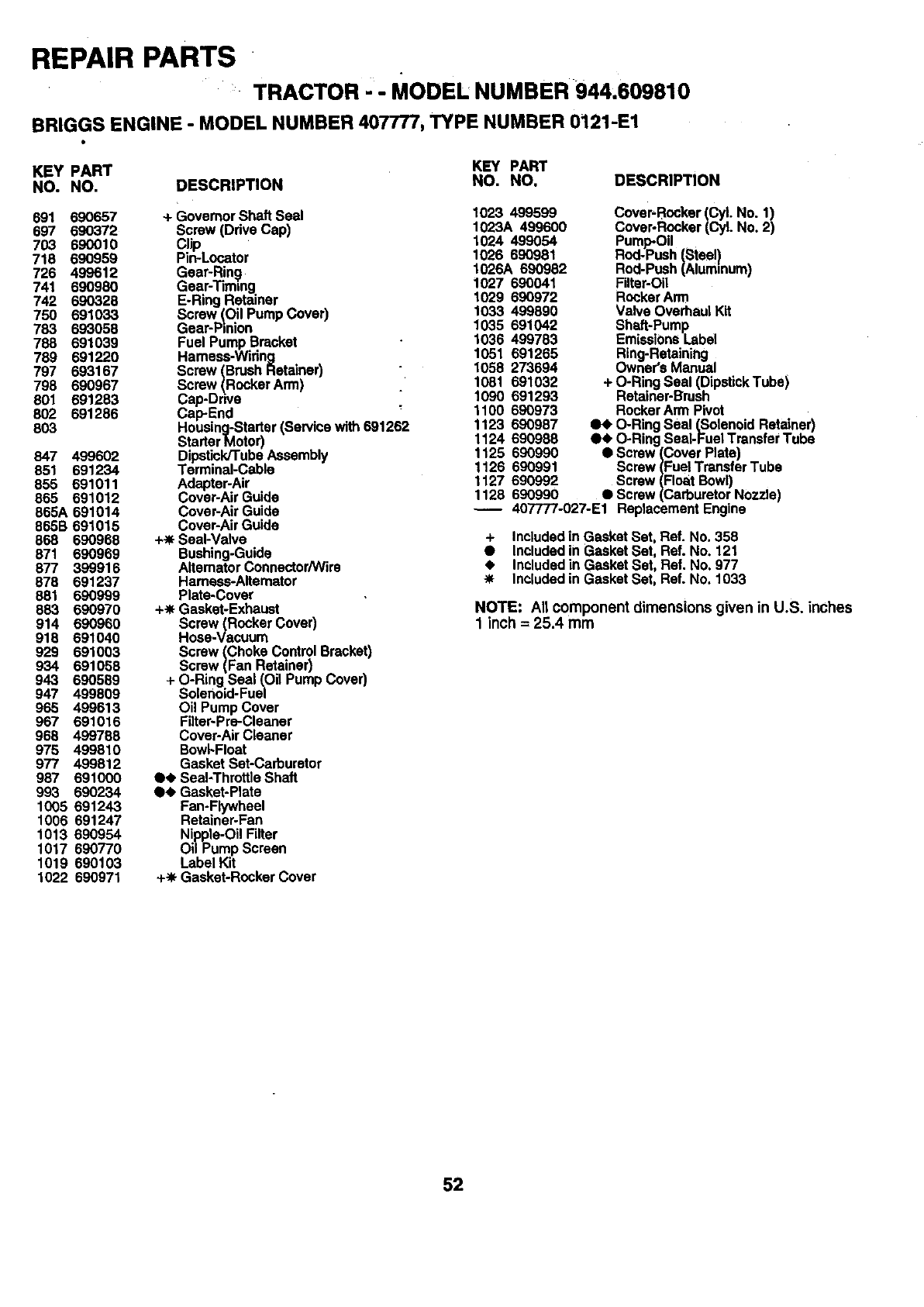
REPAIR PARTS
TRACTOR ' - MODEL NUMBER 944,609610
BRIGGS ENGINE - MODEL NUMBER 407777, TYPE NUMBER 0121-E1
KEY PART KEY PART
NO. NO. DESCRIPTION NO. NO.
L
691 690657 + GovernorShaftSeal
697 690372 Screw (Ddve Cap)
703 690010 Clip
718 690959 Pin-Locator
726 499612 Gear-Rin9
741 690980 Gear-Tirmng
742 690326 E-Ring Retainer
750 691033 Screw !Oil PumpCover)
783 693058 Gear-Pinion
788 691039 Fuel PumpBracket
789 691220 Hamess-Wiring
797 693167 Screw (BrushRetainer)
798 690967 Screw (RockerArm)
801 691283 Cap-Ddve
802 691286 Cap-End
803 Housing-Starter(Servicewith691262
StarterMotor)
847 499602 Dipstick/TubeAssembly
851 691234 Terminal-Cable
855 691011 Adapter-Air
865 691012 Cover-AirGuide
865A 691014 Cover-AirGuide
866B 691015 Cover-AirGuide
868 690968 +_ Seal-Valve
871 690969 Bushing-Guide
877 399916 AItematorConnector/Wire
878 691237 Hamass-Altemator
881 690999 Plate-Cover
883 690970 +_ Gasket-Exhaust
914 690960 Screw (RockerCover)
918 691040 Hose-Vacuum
929 691003 Screw (Choke ControlBracket)
934 691058 Screw (Fan Retainer)
943 690589 + O-RingSeal (Oil PumpCover)
947 499809 Solenoid-Fuel
965 499613 Oil PumpCover
967 691016 Filter-Pre-Cleaner
968 499768 Cover-AirCleaner
975 499810 Bowl-Float
977 499812 GasketSet-Carburetor
987 691000 O,e Seal-ThrottleShaft
993 690234 Q¢ Gasket-Plate
1005 691243 Fan-Flywheel
1006 691247 Retainer-Fan
1013 690954 Nipple-OilFilter
1017 690770 Oi/Pump Screen
1019 690103 Label Kit
1022 690971 +-_ Gasket-RockerCover
DESCRIPTION
1023 499599
1023A 499600
1024 499054
1026 690981
1026A 690982
1027 690041
1029 690972
1033 499890
1035 691042
1036 499783
1051 691265
1058 273694
1081 691032
1090 691293
1100 690973
1123 690987
1124 690988
1125 690990
1126 690991
1127 690992
1128 690990
Cover-Rocker(CyLNo. 1)
Cover-Rocker(Cyl.No. 2)
Pump-Oil
Rod-Push(Steel)
Rod-Push(Aluminum)
Filter-Oil
RockerArm
Valve OverhaulKit
Shaft-Pump
EmissionsLabel
Ring-Retaining
Owner'sManual
+ O-RingSeal (DipstickTube)
Retainer-Stash
RockerArmPivot
O4, O-Ringseal (SolenoidRetainer)
@_ O-RingSeal-FuelTransferTube
•Screw (Cover Plate)
Screw(Fuel TransferTube
Screw (Float Bowl)
•Screw(CarburetorNozzle)
407777-027-E1 ReplacementEngine
+ Includedin GasketSet, Ref. No. 358
•IncludedinGasketSet, Ref. No. 121
IncludedinGasketSet, Ref. No. 977
IncludedinGasketSet, Ref. No. 1033
NOTE: All component dimensions given in U.S, inChes
1 inch = 25.4 mm
52

I
SERVICE..........................:NOTES_
53

SERVICE .... '"
NOTES
i
54

SUGGESTED GUIDE FOR SIGHTING SLOPES FOR SAFE OPERATION
_r _ ONLY RIDE UP AND DOWN'HILL,
NOT ACROSS HILL
SIGHT AND HOLD THIS LEVEL WITH
SKY LINE OR TREE.
15° MAX.
AI
Operate your Tractor up and down the face of slopes (not I
greater than 15°.), never across the face. Make turns gradu- I
ally to prevent tipping or loss of control. Exercise extreme
caution when changing direction on slopes.
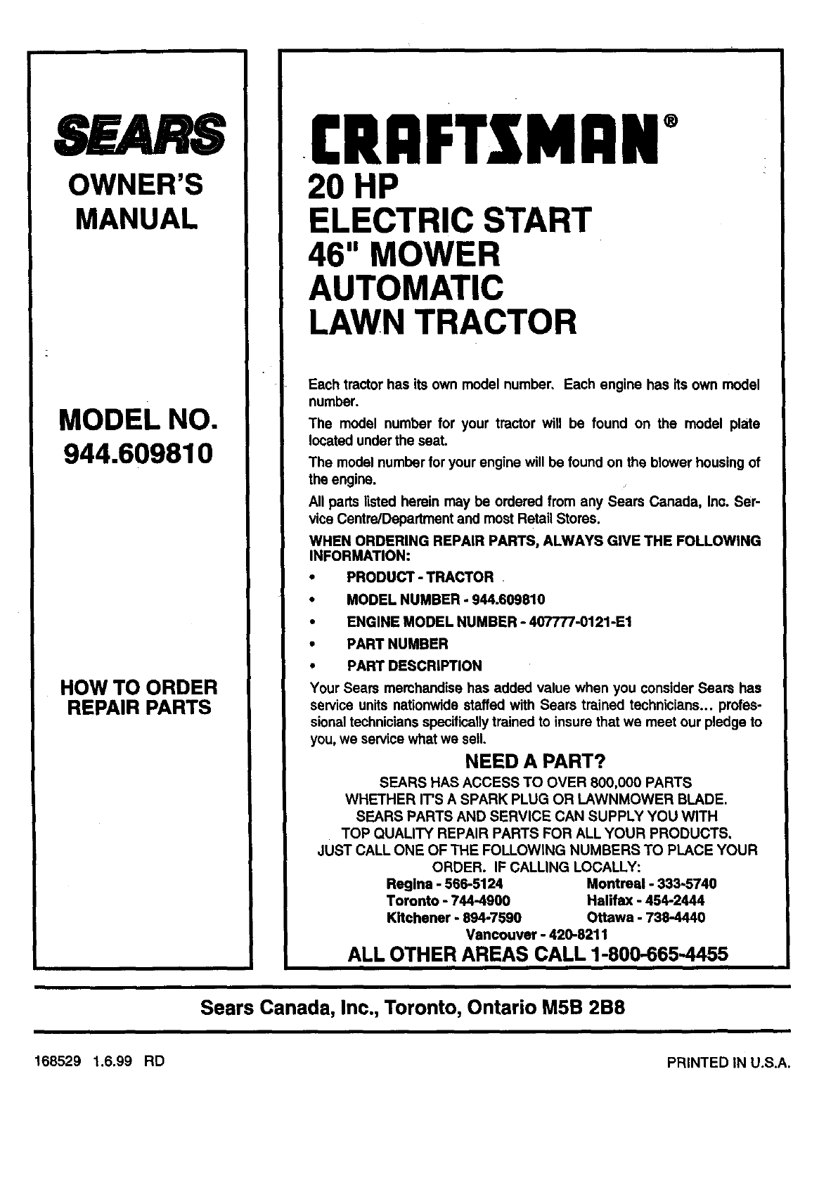
SEARS
OWNER'S
MANUAL
MODEL NO.
944.609810
HOW TO ORDER
REPAIR PARTS
.CRnFTSMnN°
2O HP
ELECTRIC START
46" MOWER
AUTOMATIC
LAWN TRACTOR
Each tractor has its own model number, Each engine has its own model
number.
The model number for your tractor will be found on the model plate
located under the seat.
The model number for your engine will be found on the blower housing of
the engine.
All parts listed heroin may be ordered from any Sears Canada, Inc, Ser-
vice Centre/Department and most Retail Stores.
WHEN ORDERING REPAIR PARTS, ALWAYS GWE THE FOLLOWING
INFORMATION:
• PRODUCT - TRACTOR
•MODEL NUMBER - 944.609810
•ENGINE MODEL NUMBER - 407777-0121-E1
•PART NUMBER
• PART DESCRIPTION
Your Sears merchandise has added value when you consider Sears has
service units nationwide staffed with Sears trained technicians.., profes-
sionaltechnicians specificallytrained to insure that we meet our pledge to
you, we service what we sell.
NEED A PART?
SEARS HAS ACCESS TO OVER 800,000 PARTS
WHETHER IT'S ASPARK PLUG OR LAWNMOWER BLADE.
SEARS PARTS AND SERVICE CAN SUPPLY YOU WITH
TOP QUALITY REPAIR PARTS FOR ALL YOUR PRODUCTS,
JUST CALL ONE OF THE FOLLOWING NUMBERS TO PLACE YOUR
ORDER. IF CALLING LOCALLY:
Regina - 566-5124 Montreal - 333-5740
Toronto -744-4900 Halifax -454-2444
Kitchener - 894-7590 Ottawa -738-4440
Vancouver -420-8211
ALL OTHER AREAS CALL 1-800-665-4455
Sears Canada, Inc., Toronto, Ontario M5B 2B8
168529 1.6.99 RD PRINTED IN U.S.A.
