Craftsman C950524302A User Manual SNOW BLOWER Manuals And Guides L0511283
CRAFTSMAN Snowthrower, Gas Manual L0511283 CRAFTSMAN Snowthrower, Gas Owner's Manual, CRAFTSMAN Snowthrower, Gas installation guides
User Manual: Craftsman C950524302A C950524302A CRAFTSMAN SNOW BLOWER - Manuals and Guides View the owners manual for your CRAFTSMAN SNOW BLOWER #C950524302A. Home:Lawn & Garden Parts:Craftsman Parts:Craftsman SNOW BLOWER Manual
Open the PDF directly: View PDF ![]() .
.
Page Count: 68
8 _ JR8
owner's
manual
Model
C950524302A
9.5 H.P. 27 inch
CAUTION:
You must read and
understand this owner's
manual before operating
unit.
Serial No.
DUAL STAGE
SNOW BLOWER
401357 SEARS CANADA INC., TORONTO, ONTARIO M5B 2B8 PrintedinU.S.A.
RULES FOR SAFE OPERATION
GeneralInformation
Thisinstructionbookiswrittenfur a personwithsomemechanicalability.
Ukemostsen_icebooks,notallthestepsaredescribod.Stepsonhowto
loosenortightenfastenersarestepsanyonecanfollowwithsome
mechanicalability.Readandfollowtheseinstructionsbeforeyouusethe
unit.
Knowyourproduct:Ifyouunderstandthe unitandhowtheunit
operates,youwillgetthebestperformance.Asyoureadthismanual,
comparetheillustrationstotheunit.LearntheIocaUonandthefunctionof
thecontrols.Tohelppreventanaccident,followtheoperatinginstructions
andthesafetyrules.Keepthismanualforfuturereference.
IMPORTANT:Manyunitsarenotassembledandaresoldincartons.It is
theresponsibilityoftheownertomakesuretheassemblyinstructionsin
thismanualareexactlyfollowed.Otherunitsarepurchasedinan
assembledcondflion.Onassembledunits,itistheresponsibilityofthe
ownertomakesuretheunitiscorrectlyassembled.Theownermust
carefullychecktheunitaccordingtotheinstructionsinthismanualbefore
itisfirstused.
Thismanualcon_nssafetyinformationtomakeyou
awareofthehazardsanddsksassociatedwithsnow
throwers,andhowtoavoidthem.Thesnowthrowerisdesignedand
intendedforremovalofsnow,andshouldnotbeusedforanyother
purpose.It isimportantthatyoureadandunderstandthese
instructions,andanyoneoperatingtheequipmentreadand
understandthoseinstructions.
_,WARNING I
Theengineexhaustfromthisproductcontainschemicalsknowntothe
StateofCaliforniatocausecancer,birthdefects,orotherreproductive
harm.
Asignalword(DANGER,WARNING,or CAUTION)isusedwiththealert
symboltoindicatethelikelihoedandthepotentialseverityofinjury.In
addition,ahazardsymbolmaybeusedtorepresentthetypeofhazard.
_k DANGERindicatesahazardwhich,ifnotavoided,willresultIn
deathorseriousinjury.
WARNINGindicatesahazardwhich,ifnotavoided,couldresult
indeathorseriousinjury.
CAUTIONindicatesahazardwhich,ifnotavoided,mightresult
inminorormoderateInjury.
CAUTION,whenusedwithoutthealertsymbol,indicatesa
situationthatcouldresultindamagetotheequipmenL
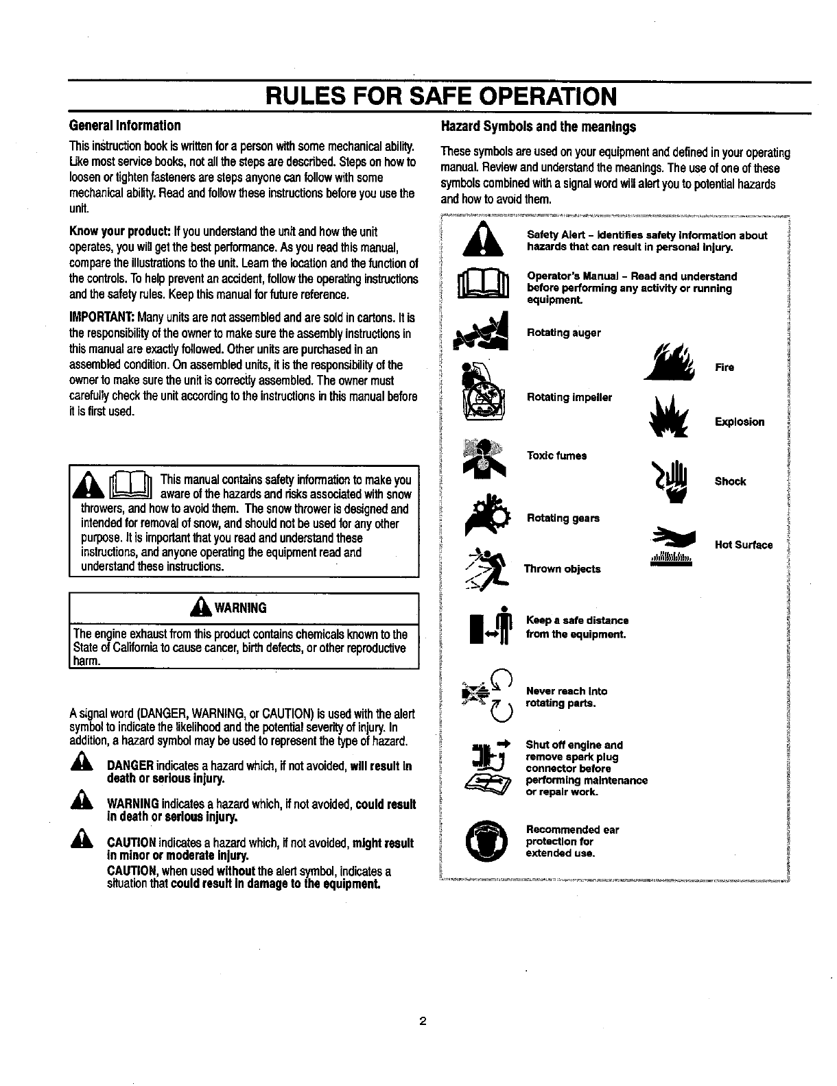
HazardSymbolsand the meanings
Thesesymbolsareusedonyourequipmentanddefinedinyouroperating
manual.Reviewandunderstandthemeanings.Theuseofoneofthese
symbolscombinedwithasignalwordwillalertyoutopotentialhazards
andhowtoavoidthem.
ASafety Alert -Identifies safety Information about
hazards that can result in personal Injury.
Operator's Manual -Read and understand
before performing any activity or running
equipment.
Rotating auger
Rotating impeller
Fire
Explosion
Toxlcfumes
Rotating gears
_Thrown objects
.J}=l[ll,fJS,..
Elm
Shock
Hot Surface
o
I<,,1,_ eep a safe distancefrom the equipment.
Never reach Into
rotating parts.
_]j_=$' Shot off engine and
remove spark plug
connector before
performing maintenance
or repair work.
(_ Recommended ear
protection for
extended use.
RULES FOR SAFE OPERATION
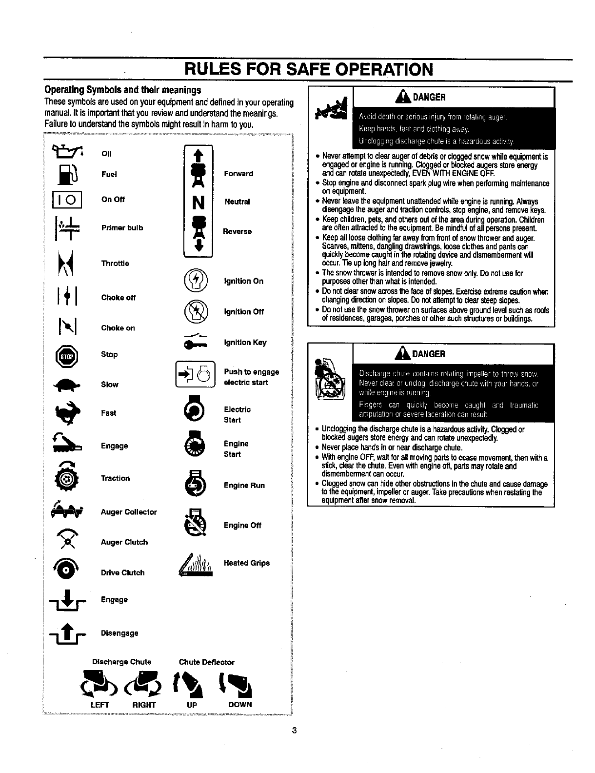
OperatingSymbols andtheir meanings
Thesesymbolsareusedon yourequipmentanddefinedinyouroperating
manual It is importantthatyoureviewand understandthemeanings.
Failureto understandthe symbolsmightresultinharmto you.
011 T
._ Fuel -- Forward
On Off NNeutral
__. Palmerbulb Reverse
_\_ Throttle
(_ IgnitionOn
I+1 Cho.o,
IgnitionOff
I'_lt_I Choke on
IgnitionKey
(_ Stop
Pushto engage
Slow electricstart
lb Fast _) Electric
Start
I_ Engage _Engine
Start
Traction _) Engine Run
"_ Auger Collector _Engine Off
Auger Clutch
Drive Clutch _Heated Grips
Engage
Disengage
Discharge Chute Chute Deflector
LEFT RIGHT UP DOWN
I_ _IL DANGER
•Neverattempttoclearaugerofdebrisordoggedsnowwhileequipmentis
engagedorengineisrunning.Cloggedorbfsckedaugersstoreenergy
andcanrotateunexpe_:tedly,EVENWITHENGINEOFR
•Stopengineanddisconnectsparkplugwirewhenperformingmaintenance
onequipment.
• Neverleavetheequipmentunattendedwhileengineisrunning.Always
disengagetheaugerandtractioncontrols,stopengine,andremovekeys.
•Keepchildren,pets,andothersoutoftheareaduringoperation.Childrefl
areoftenattractedtotheequipment.Bemindfulofallparsonspresent.
•Keepalllooseclothingfarawayfromfrontofsnowthrowerandauger.
Scarves,mittens,danglingdrawstrings,looseclothesandpantscan
quicklybecomecaughtin therefutingdevicaanddismembermentwill
occur."fieuplonghairandremovejewelry.
•Thesnowthrowerisintendedtoremovesnowonly.Donotusefur
purposesothertheewhatis intended.
•Donotdearsnowaumssthefaceofslopes.Exerdseextremecan_onwhen
changingdirectiononslopes.Donotattempttodearsteepslopes.
•Donotusethesnowthroweronsurfasesabovegroundlevelsuchasroofs
of residences,garages,porchesorothersuchstructuresorbuildings.
,_k DANGER
•Uncloggingthedischargechuteisa hazardousactivity.Cloggedor
blockedaugersstoreenergyandcanrotateunexpectedly.
•Neverplacehandsinorneardischargechute.
•WithengineOFF,waitforallmovingpartstoceasemovement,thenwitha
stick,deerthechute.Evenwithengineoff,partsmayrotateand
dismembermentcanoccur.
•Cloggedsnowcanhideotherobstructionsinthechuteandcausedamage
totheequipment,impellerorauger.Takeprecautionswhenrestatingthe
equipmentaftersnowremoval.
RULES FOR SAFE OPERATION
_kDANGER
• Beawareofyourenvironmentwhileoperatingequipment.Runningover
itemssuchas graveldoormats,newspapers,toys,androckshidden
undersnow,canall bethrownfromchuteoram ntheauger.
• Alwaysbeawareofthedirectionthesnowisbeingthrown.Nearby
pedestrians,petsorpropertymaybeharmedbyobjectsbeingthrown.
•Famitiaitzeyearsalfwiththeareayooptantowork.Markoffbo_ed_es of
walkwaysanddrivewaystopreventpropertydamagefromthrownobjects.
•Takecautionwhensnowthrowinginunfamiliarareas.Stayalertforhidden
hazardsandtraffic.
•Afterstrikinga foreignobject,turnengineOFF,waitformovingpartsto
ceasemovement,andcheckimmedietalyfordamage.Ifdamaged,repair
beforestartingandoperatingsnowthrower.
•WithengineOFF,waitformovingpartstostopandalwaysuseastickto
cleardischargechute.
•Ifunitvibratesabnormally,turnengineOFF.Vibrationisgenerallya
warningoftrouble.Seeanauthodzeddealerifnecessaryforrepairs.
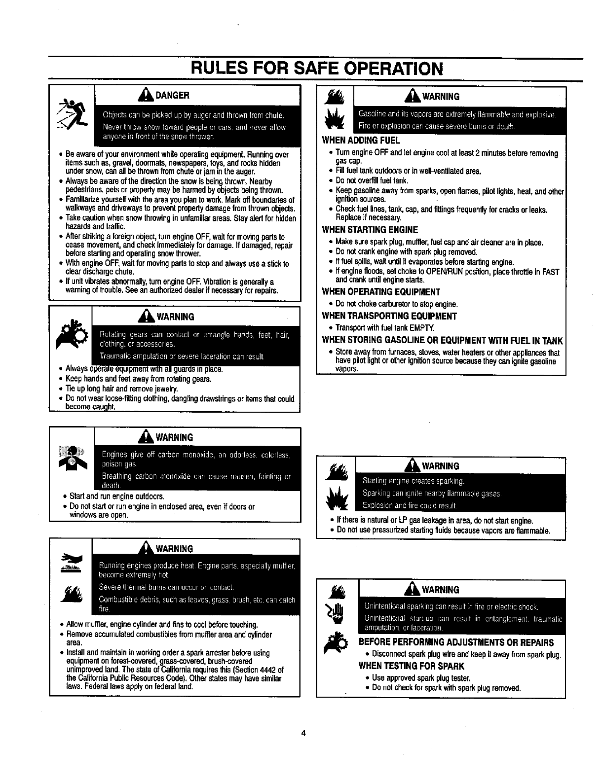
,_WARNING
AWARNING
WHEN ADDING FUEL
•TurnengineOFFandlet enginecoolatleast2 minutesbeforeremoving
gascap.
•Fm fualtankoutdoorsorIn weU-ventilatadarea.
•Donotoverfillfuel tank.
•Keepgasolineawayfromsparks,openflames,pilotlights,heat,andnthe
ignitionsources.
•Checkfuellines,tank,cap,andfittingsfrequentlyforcracksorleaks.
Replaceifnecessary.
WHEN STARTINGENGINE
•Makesuresparkplug,muffler,fuelcapandaircteanerarein place.
•Donotcrankenginewithsparkplugremoved.
• If fuelspills,waituntilit evaporatesbeforestartingengine,
•Ifenginefloods,setchoketoOPEN/RUNpea'_on,ptacethrottleinFAST
andcrankuntilenginestarts.
WHEN OPERATING EQUIPMENT
• Donotchokecarburetortostopengine.
WREN TRANSPORTINGEQUIPMENT
•TransportwithfueltankEMPTY.
WHEN STORING GASOLINEOR EQUIPMENTWITH FUEL INTANK
•Storeawayfromfurnaces,stoves,waterheatersorotherappliancesthat
havepilotlightorotherignitionsourcebecausetheycanignitegasoline
vapors.
,_k WARNING
• Start andr_nangineoutdoors.
•Donotstartorrunengineinenclosedarea,evenif doorsor
windowsareopen.
WARNING
• Allowmuffler,enginecylinderandfinstocoolbeforetouching.
•Removeaccumulatedcombustiblesfrommufflerareaandcylinder
area.
•Installandmaintaininworkingordera sparkarresterbeforeusing
equipraentonforest-coveredgmss-oovered,brush-covered
unimprovedland.ThestateofCaliforniarequiresthis(Section4442of
theCaliforniaPublicResourcesCode).Otherstatesmayhavesimilar
laws.Federallawsapplyonfederalland.
• Donntusepressudzedstartingfluidsbecassev_orsareflammable.
WARNING
BEFOREPERFORMINGADJUSTMENTSOR REPAIRS
•DiSConnectsparkplugwireandkeepitawayfromsparkplug.
WHENTESTING FORSPARK
•Useapprovedsparkplugtester.
•Donotcheckforsparkwithsparkplugremoved.
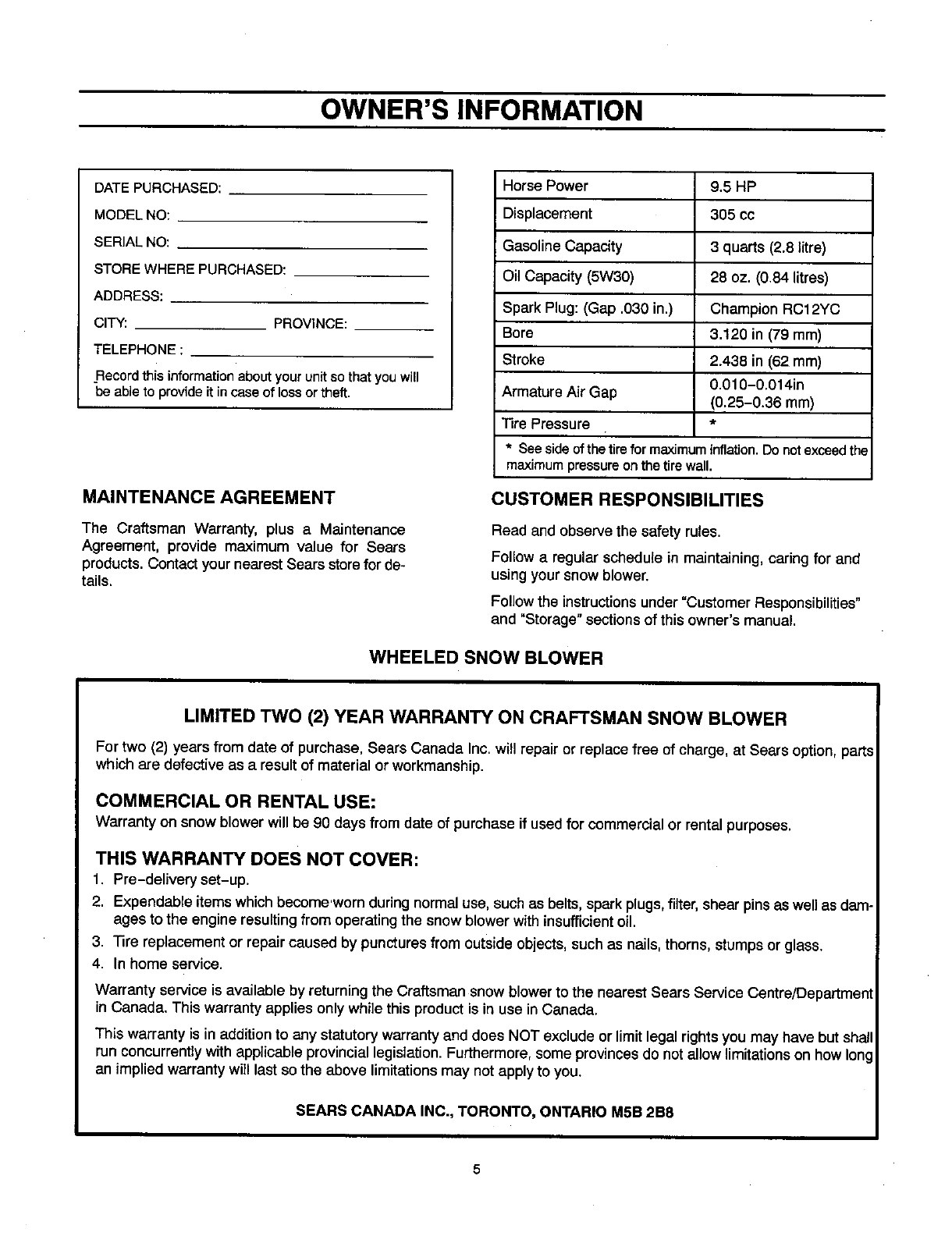
OWNER'S INFORMATION
DATE PURCHASED:
MODEL NO:
SERIAL NO:
STORE WHERE PURCHASED:
ADDRESS:
CITY: PROVINCE:
TELEPHONE :
Record this information about your unit so that you will
be able to provide it in case of loss or theft.
MAINTENANCE AGREEMENT
The Craftsman Warranty, plus a Maintenance
Agreement, provide maximum value for Sears
products. Contact your nearest Sears store for de-
tails.
Horse Power 9.5 HP
Displacement 305 cc
Gasoline Capacity 3 quarts (2.8 litre)
Oil Capacity (5W30) 28 oz. (0.84 litres)
Spark Plug: (Gap .030 in.) Champion RC12YC
Bore 3.120 in (79 mm)
Stroke 2.438 in (62 mm)
0.010-0.014in
Armature Air Gap (0.25-0.36 mm)
Tire Pressure *
• Seeside ofthe tire for maximuminflation.Do not exceedthe
maximumpressureonthe tire wall.
CUSTOMER RESPONSIBILITIES
Read and observe the safety rules.
Follow a regular schedule in maintaining, caring for and
using your snow blower.
Follow the instructions under "Customer Responsibilities"
and "Storage" sections of this owner's manual.
WHEELED SNOW BLOWER
LIMITED TWO (2) YEAR WARRANTY ON CRAFTSMAN SNOW BLOWER
For two (2) years from date of purchase, Sears Canada Inc, will repair or replace free of charge, at Sears option, parts
which are defective as a resultof material or workmanship,
COMMERCIAL OR RENTAL USE:
Warranty on snow blowerwill be 90 daysfrom date of purchase if usedfor commercial or rental purposes.
THIS WARRANTY DOES NOT COVER:
1. Pre-delivery set-up.
2. Expendable itemswhich become'worn duringnormal use, suchas belts,spark plugs,filter,shear pinsas well as dam-
ages to the engine resultingfrom operating the snow blower withinsufficient oil.
3. Tire replacement or repair caused by puncturesfrom outside objects, such as nails,thorns, stumpsor glass.
4. In home service.
Warranty service is available by returningthe Craftsman snow blower to the nearest Sears Service Centre/Department
in Canada. This warranty applies only while this product is in use in Canada.
This warranty is in addition to any statutory warranty and does NOT exclude or limit legal rights you may have but shall
run concurrently with applicable provincial legislation. Furthermore, some provinces do not allow limitations on how Iorl
an implied warranty will last so the above limitations may not apply to you.
SEARS CANADA INC., TORONTO, ONTARIO M5B 2B8
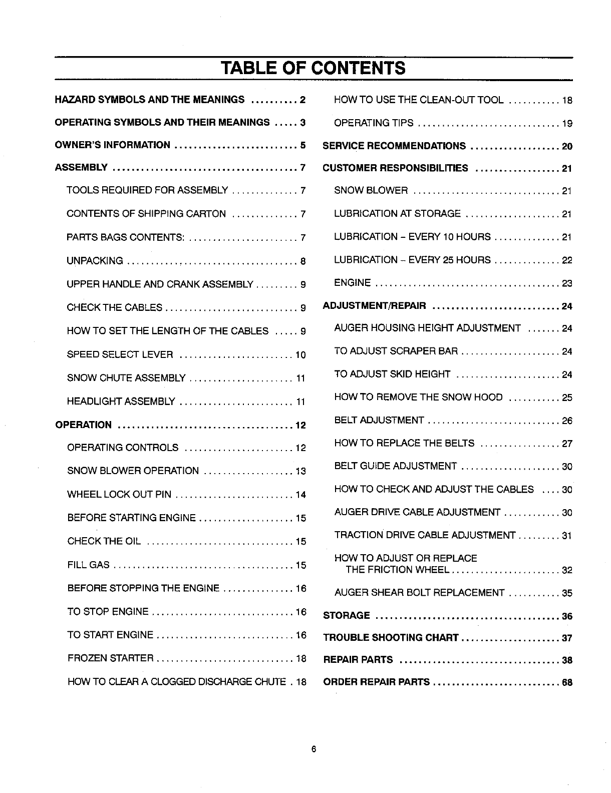
TABLE OF CONTENTS
HAZARD SYMBOLS AND THE MEANINGS .......... 2
OPERATING SYMBOLS AND THEIR MEANINGS ..... 3
OWNER'S INFORMATION .......................... 5
ASSEMBLY ....................................... 7
TOOLS REQUIRED FOR ASSEMBLY .............. 7
CONTENTS OF SHIPPING CARTON .............. 7
PARTS BAGS CONTENTS: ....................... 7
UNPACKING .................................... 8
UPPER HANDLE AND CRANK ASSEMBLY ......... 9
CHECK THE CABLES ............................ 9
HOW TO SET THE LENGTH OF THE CABLES ..... 9
SPEED SELECT LEVER ........................ 10
SNOW CHUTE ASSEMBLY ...................... 11
HEADLIGHT ASSEMBLY ........................ 11
OPERATION ..................................... 12
OPERATING CONTROLS ....................... 12
SNOW BLOWER OPERATION ................... 13
WHEEL LOCK OUT PIN ......................... 14
BEFORE STARTING ENGINE .................... 15
CHECK THE OIL ............................... 15
FILL GAS ...................................... 15
BEFORE STOPPING THE ENGINE ............... 16
TO STOP ENGINE .............................. 16
TO START ENGINE ............................. 16
FROZEN STARTER ............................. 18
HOW TO CLEAR A CLOGGED DISCHARGE CHUTE . 18
HOW TO USE THE CLEAN-OUT TOOL ........... 18
OPERATING TIPS .............................. 19
SERVICE RECOMMENDATIONS ................... 20
CUSTOMER RESPONSIBILITIES .................. 21
SNOW BLOWER ............................... 21
LUBRICATION AT STORAGE .................... 21
LUBRICATION - EVERY 10 HOURS .............. 21
LUBRICATION - EVERY 25 HOURS .............. 22
ENGINE ....................................... 23
ADJUSTMENT/REPAIR ........................... 24
AUGER HOUSING HEIGHT ADJUSTMENT ....... 24
TO ADJUST SCRAPER BAR ..................... 24
TO ADJUST SKID HEIGHT ...................... 24
HOW TO REMOVE THE SNOW HOOD ........... 25
BELT ADJUSTMENT ............................ 26
HOW TO REPLACE THE BELTS ................. 27
BELT GUIDE ADJUSTMENT ..................... 30
HOW TO CHECK AND ADJUST THE CABLES .... 30
AUGER DRIVE CABLE ADJUSTMENT ............ 30
TRACTION DRIVE CABLE ADJUSTMENT ......... 31
HOW TO ADJUST OR REPLACE
THE FRICTION WHEEL ....................... 32
AUGER SHEAR BOLT REPLACEMENT ........... 35
STORAGE ....................................... 36
TROUBLE SHOOTING CHART ..................... 37
REPAIR PARTS .................................. 38
ORDER REPAIR PARTS ........................... 68
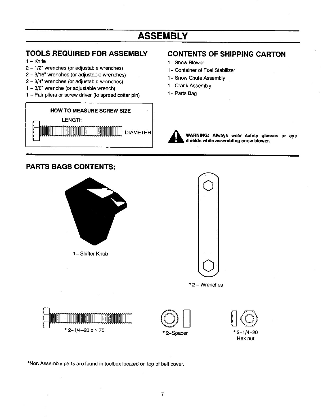
ASSEMBLY
TOOLS REQUIRED FOR ASSEMBLY
1-Knife
2-1/2"wrenches (or adjustable wrenches)
2-9/16" wrenches (or adjustable wrenches)
2-3/4"wrenches (or adjustable wrenches)
1 - 3/8" wrenche (or adjustable wrench)
1 - Pair pliers or screw driver (to spread cotter pin)
CONTENTS OF SHIPPING CARTON
1- Snow Slower
1-Container of Fuel Stabilizer
1-Snow Chute Assembly
1-Crank Assembly
1- Parts Bag
HOW TO MEASURE SCREW SIZE
_DIAMETER _hb WARNING: Always wear safety glasses or eye
shields while assembling snow blower.
PARTS BAGS CONTENTS:
1-Shifter Knob
OI
OI
* 2 - Wrenches
* 2-1/4-20 x 1.75 ©@
*2-Spacer *2-1/4-20
Hex nut
*Non Assembly parts are found in toolbox located on top of belt cover.
7
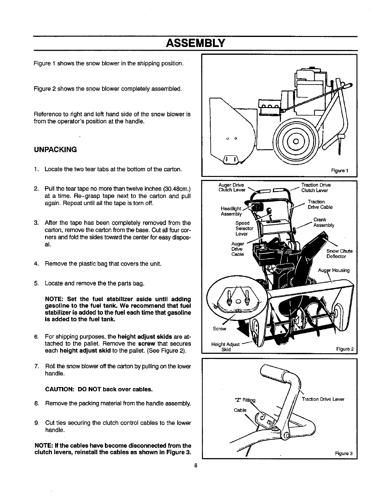
ASSEMBLY
Figure 1 shows the snow blower in the shipping position.
Figure 2 shows the snow blower completely assembled.
Reference to right and left hand side of the snow blower is
from the operator's position at the handle.
UNPACKING
1. Locate the two tear tabs at the bottom of the carton.
2. Pull the tear tape no more than twelve inches (30.48cm.)
at a time, Re-grasp tape next to the carton and pull
again. Repeat until atl the tape is torn off.
3. After the tape has been completely removed from the
carton, remove the carton from the base. Cut all four cor-
ners and fold the sides toward the center for easy dispos-
al.
4. Remove the plastic bag that covers the unit.
5. Locateand remove the the parts bag.
NOTE: Set the fuel stabilizer aside until adding
gasoline to the fuel tank. We recommend that fuel
stabilizer is added to the fuel each time that gasoline
is added to the fuel tank.
6.
7,
For shipping purposes,the height adjust skids are at-
tached to the pallet. Remove the screw that secures
each height adjust skid to the pallet. (See Figure 2).
Roll the snow blower off the carton by pulling on the lower
handle.
CAUTION: DO NOT back over cables.
8. Remove the packing material fromthe handle assembly.
9. Cut ties securing the clutch control cables to the lower
handle.
NOTE: If the cables have become disconnected from the
clutch levers, reinstall the cables as shown in Figure 3.
AugerDr_e
Clutch Lever
Assembly
Speed
Selector
Lever
Drive
Cable
Screw
Height Adjust
Skid
Cable
Figure 1
Traction Ddve
Figure 2
Figure 3
8
ASSEMBLY
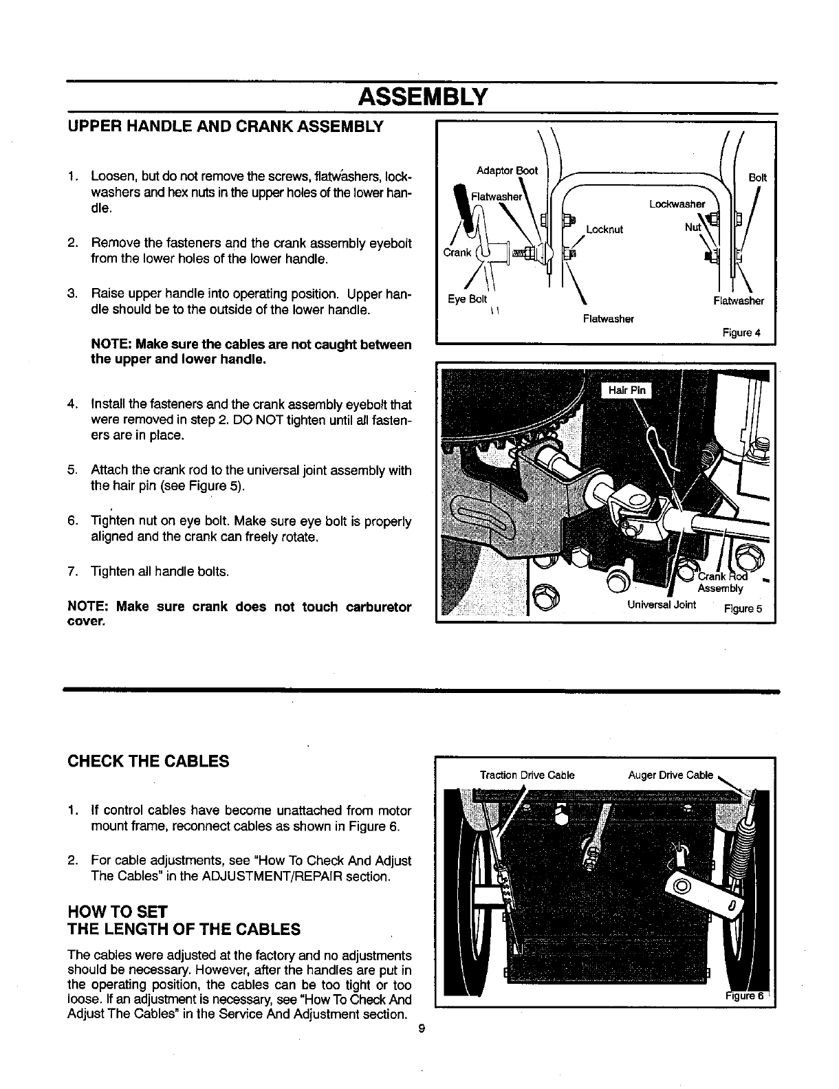
UPPER HANDLE AND CRANK ASSEMBLY
1,
2*
Loosen, but do not remove the screws, flatw'ashers, lock-
washers and hex nuts in the upper holes of the lowerhan-
dle.
Remove the fasteners and the crank assembly eyebolt
from the lower holes of the lower handle.
Lockwasher
Locknut
Bolt
3. Raise upper handle into operating position. Upper han- EyeBolt
die should be to the outside of the lower handle. _
NOTE: Make sure the cables are not caught between
the upper and lower handle,
4. Install the fasteners and the crank assembly eyebalt that
were removed in step 2. DO NOT tighten until all fasten-
ers are in place.
5. Attach the crank rod to the universal joint assembly with
the hair pin (see Figure 5).
6. Tighten nut on eye bolt. Make sure eye bolt is properly
aligned and the crank can freely rotate.
7. Tighten all handle bolts.
NOTE: Make sure crank does not touch carburetor
cover.
Flatwasher
Flatwasher
Figure 4
Assembly
Universal Joint Figure 5
CHECKTHECABLES
1. If control cables have become unattached from motor
mount frame, reconnect cables as shown in Figure 6.
2. For cable adjustments, see "How To Check And Adjust
The Cables" inthe ADJUSTMENT/REPAIR section.
HOW TO SET
THE LENGTH OF THE CABLES
The cables were adjusted at the factory and no adjustments
should be necessary. However, after the handles are put in
the operating position, the cables can be too tight or too
loose. If an adjustment is necessary, see "How To Check And
Adjust The Cables" in the Service And Adjustment section.
Traction Drive Cable
9
Auger Drive Cable
ASSEMBLY
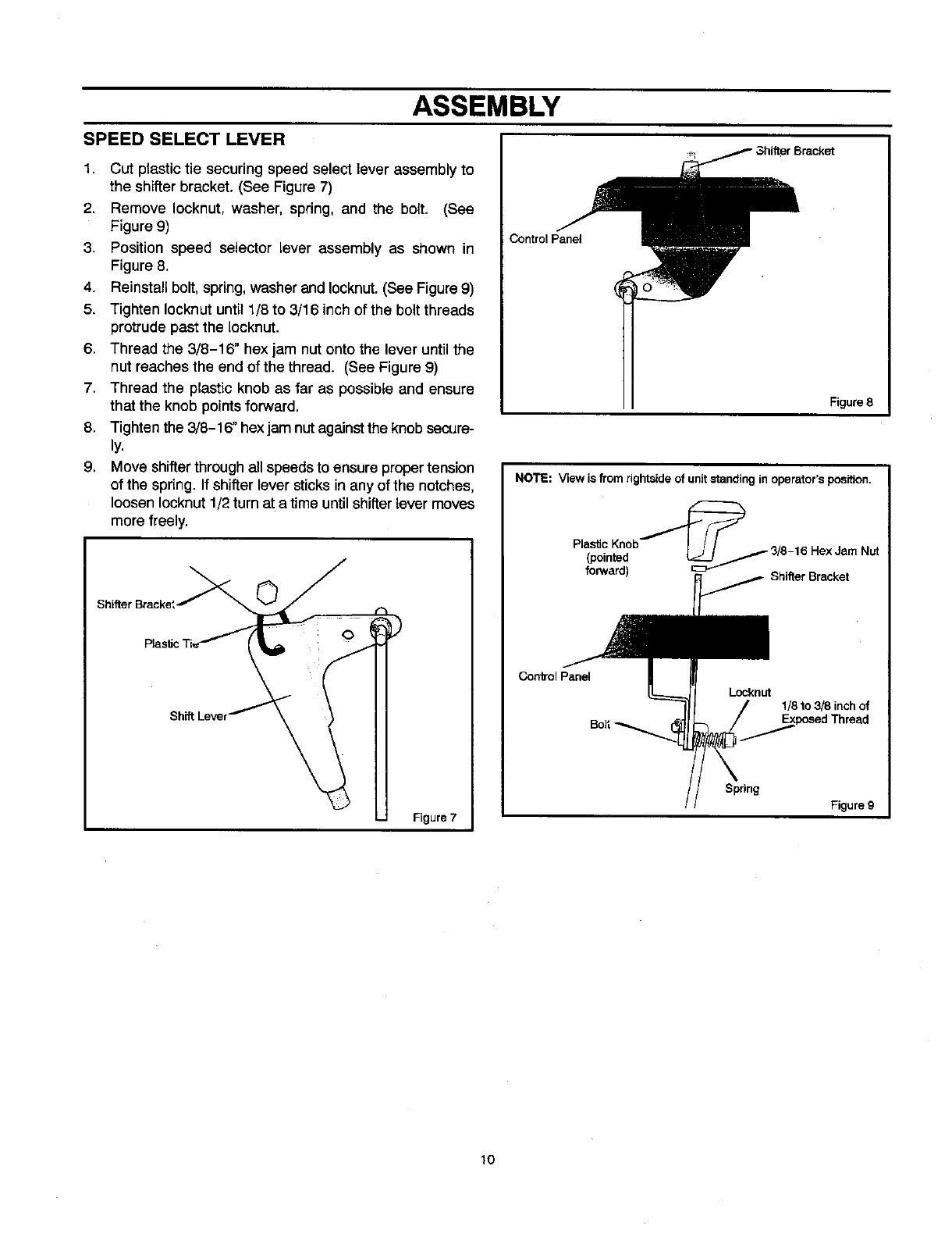
SPEED SELECT LEVER
1. Cut plastic tie securing speed select lever assembly to
the shifter bracket. (See Figure 7)
2. Remove Iocknut, washer, spring, and the bolt, (See
Figure 9)
3, Position speed selector lever assembly as shown in
Figure 8.
4, Reinstall bolt, spring, washer and Iocknut. (See Figure 9)
5. Tighten Iocknut until 1/8 to 3/16 inch of the bolt threads
protrude past the locknut.
6. Thread the 3/8-16" hex jam nut onto the lever until the
nut reaches the end of the thread. (See Figure 9)
7. Thread the plastic knob as far as possible and ensure
that the knob points forward.
8. Tighten the 3/8-16" hex jam nut against the knob secure-
ly.
9. Move shifter through all speeds to ensure proper tension
of the spdng. If shifter lever sticks in any of the notches,
loosen Iocknut 1/2 turn at a time until shifter lever moves
more freely.
Shifter Bracke',_
Figure 7
Control Panel
Figure 8
NOTE: View is from rightside of unit standing in operator's position.
Plastic Kn°b_c:_._..,,,,,_ 38__ 16 HexJ
(pointed /-am Nut
forward) Shifter Bracket
ConlrolPanel
Locknut
1/8 to 3/8 inch of
Spring
Figure g
lO
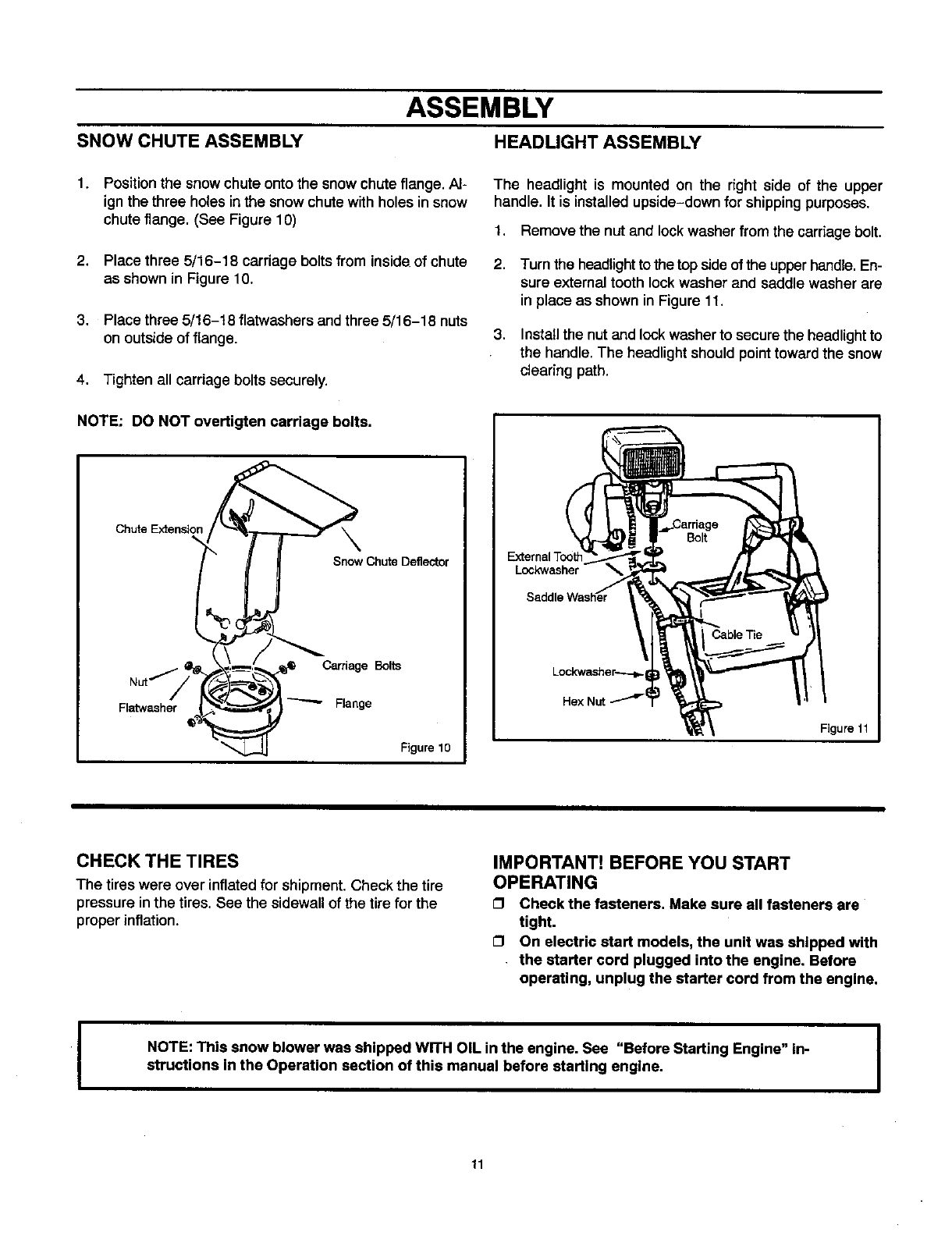
SNOW CHUTE ASSEMBLY
ASSEMBLY
HEADLIGHT ASSEMBLY
1. Position the snowchute onto the snow chuteflange. Al-
ign the three holes in the snow chute with holes in snow
chute flange. (See Figure 10)
2. Place three 5/16-18 carriage bolts from inside of chute
as shown in Figure 10.
3. Place three 5/16-18 flatwashers and three 5/16-18 nuts
on outside of flange.
4. Tighten all carriage bolts securely.
NOTE: DO NOT overtigten carriage bolts.
Chute Extension \
Snow Chu_Defle_or
Carriage Bolts
Nut/
Flatwasher Flange
Figure 10
The headlight is mounted on the right side of the upper
handle. It is installed upside-down for shipping purposes.
1, Remove the nut and lockwasher from the carriagebolt.
2. Turn the headlight to the top side of the upper handle. En-
sure external tooth lock washer and saddle washer are
in place as shown in Figure 11.
3. Installthe nut and lock washer to secure the headlight to
the handle. The headlight should point toward the snow
clearing path.
External Tool
Lockwasher
Lockwasher---_
Figure 11
CHECK THE TIRES
The tires were over inflated for shipment. Check the tire
pressure in the tires. See the sidewall of the tire for the
proper inflation.
IMPORTANT! BEFORE YOU START
OPERATING
OCheck the fasteners. Make sure all fasteners are
tight.
GI On electric start models, the unit was shipped with
the starter cord plugged into the engine. Before
operating, unplug the starter cord from the engine.
NOTE: This snow blower was shipped WITH OIL in the engine. See "Before Starting Engine" in-
structions in the Operation section of this manual before starting engine.
11
OPERATION
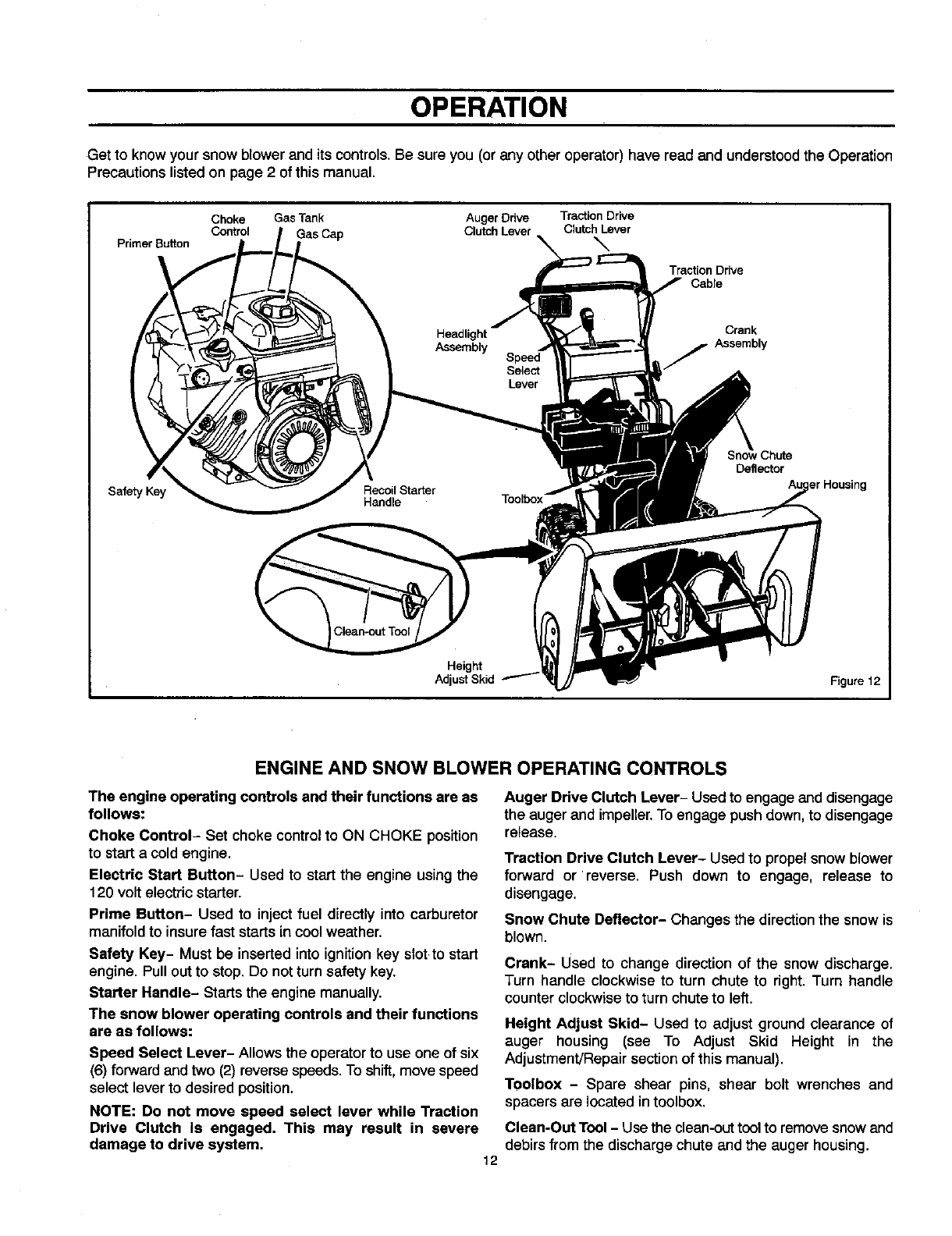
Get to know your snow blower and its controls. Be sure you (or any other operator) have read and understood the Operation
Precautions listed on page 2 of this manual.
Primer Button
Choke Gas Tank Auger Drive Traction Drive
Control Clutch Lever Clutch Lever
\
Traction Drive
Cable
Crank
Assembly
Safety Key
Deflector
Height
Adjust Skid Figure 12
ENGINE AND SNOW BLOWER OPERATING CONTROLS
The engine operating controls and their functions are as
follows:
Choke Control- Set choke control to ON CHOKE position
to start a cold engine.
Electric Start Button- Used to start the engine usingthe
120 volt electric starter.
Prime Button- Used to inject fuel directly into carburetor
manifoldto insure fast starts in cool weather.
Safety Key- Must be inserted into ignitionkey slot to start
engine. Pull out to stop. Do not turn safety key.
Starter Handle- Starts the engine manually.
The snow blower operating controls and their functions
are as follows:
Speed Select Lever- Allowsthe operator to use one of six
(6) forwardand two (2) reversespeeds.To shift,move speed
select lever to desired position.
NOTE: Do not move speed select lever while Traction
Drive Clutch Is engaged. This may result in severe
damage to drive system. 12
Auger Drive Clutch Lever- Used to engage and disengage
the auger and impeller.To engage push down,to disengage
release.
Traction Drive Clutch Lever- Used to propel snow blower
forward or reverse. Push down to engage, release to
disengage.
Snow Chute Deflector- Changes the direction the snow is
blown.
Crank- Used to change direction of the snow discharge.
Turn handle clockwise to turn chute to right. Turn handle
counter clockwise to turn chute to left.
Height Adjust Skid- Used to adjust ground clearance of
auger housing (see To Adjust Skid Height in the
Adjustment/Repair section of this manual).
Toolbox - Spare shear pins, shear bolt wrenches and
spacers are located in toolbox.
Clean-Out Tool - Use the clean-out tool to remove snowand
debirsfrom the discharge chute and the auger housing.
OPERATION
The operation of any snow blower can result in foreign objects being thrown into the eyes,which can
result in severe eye damage. Always wear safety glasses or eye shields before beginning snow blower
Operation. We recommend standard safety glasses or Wide Vision Safety Mask for over spectacles.
SNOW BLOWER OPERATION
The most effective use of the snowblower will be established
by experience, taking into consideration the terrain, wind
conditions and building location which will determine the
direction of the discharge chute.
NOTE: Do not blow snow towards a building as hidden
objects could be blown with sufficient force to cause
damage.
1. Start the engine as described insection "ToStart Engine"
(see Figure 14).
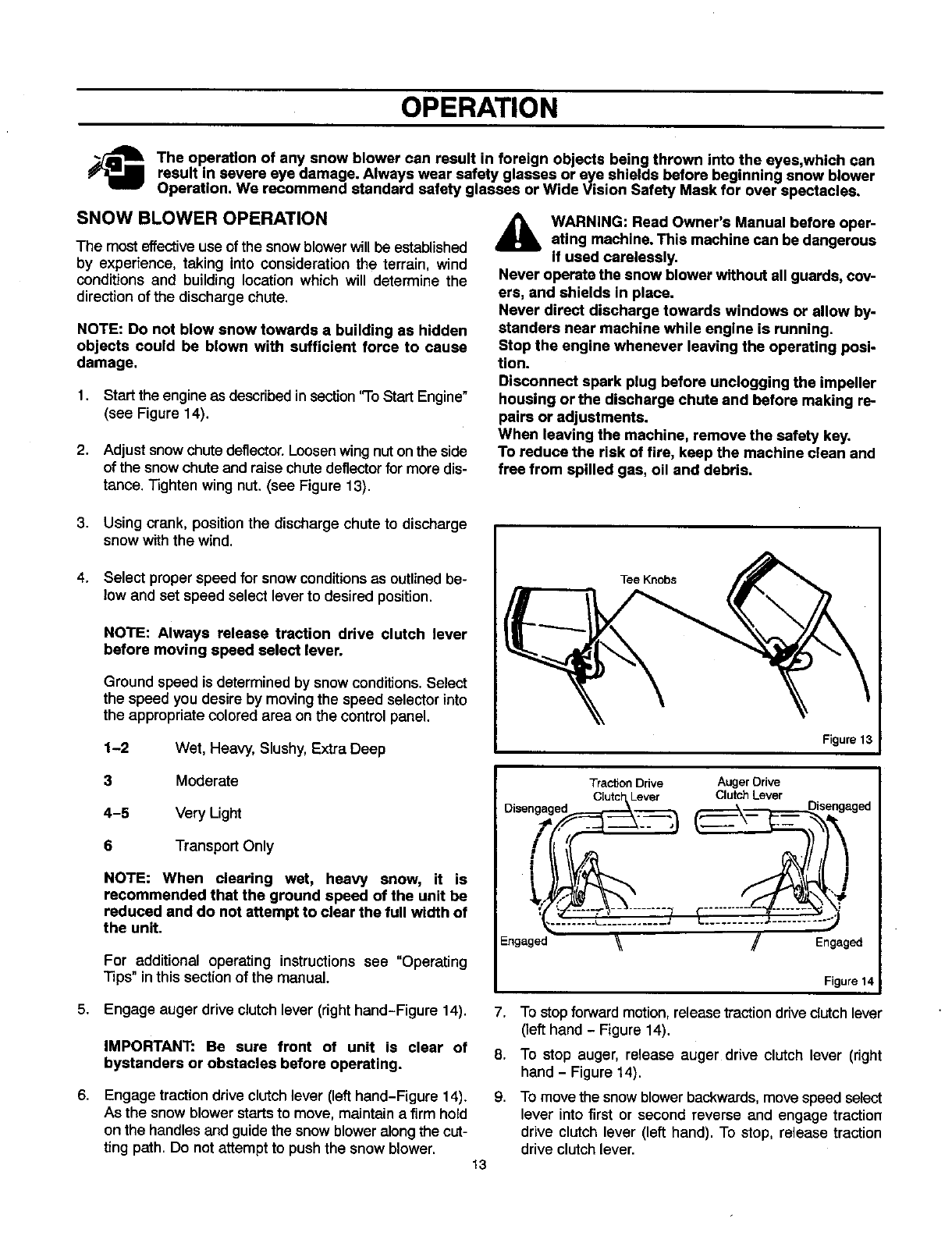
2. Adjust snow chute deflector. Loosen wing nut on the side
of the snow chute and raise chute deflector for more dis-
tance. Tighten wing nut. (see Figure 13).
_[b ARNING: Read Owner's Manual before oper-
ating machine. This machine can be dangerous
if used carelessly.
Never operate the snow blower without all guards, cov-
ers, and shields in place.
Never direct discharge towards windows or allow by-
standers near machine while engine is running.
Stop the engine whenever leaving the operating posi-
tion.
Disconnect spark plug before unclogging the impeller
housing or the discharge chute and before making re-
pairs or adjustments.
When leaving the machine, remove the safety key.
To reduce the risk of fire, keep the machine clean and
free from spilled gas, oil and debris.
3,
4.
Using crank, position the discharge chute to discharge
snow with the wind.
Select proper speed for snow conditionsas outlined be-
low and set speed select lever to desired position.
NOTE: Always release traction drive clutch lever
before moving speed select lever.
Ground speed is determined by snowconditions. Select
the speed you desire by moving the speed selector into
the appropriate colored area on the control panel.
1-2 Wet, Heavy, Slushy, Extra Deep
3Moderate
4-5 Very Light
6Transport Only
NOTE: When clearing wet, heavy snow, it is
recommended that the ground speed of the unit be
reduced and do not attempt to clear the full width of
the unit.
For additional operating instructions see "Operating
Tips" in this sectionof the manual.
5. Engage auger drive clutch lever (right hand-Figure 14).
6,
IMPORTANT: Be sure front of unit is clear of
bystanders or obstacles before operating.
Engage tractiondrive clutch lever (left hand-Figure 14).
As the snow blower starts to move, maintain a firm hold
on the handles and guide the snow blower along the cut-
ting path. Do not attempt to push the snow blower.
Tee Knobs
Figure 13
13
Traction Drive Auger Drive
Disengaged C'l 'ch [e_ r_ ---'--'-_ Clu_h Lever g_
Engaged _/Engaged
Figure 14
7. To stop forwardmotion, release tractiondrive dutch lever
(left hand - Figure 14).
8. To stop auger, release auger drive clutch lever (right
hand - Figure 14).
9. To move the snow blower backwards, move speed select
lever into first or second reverse and engage traction
drive clutch lever (left hand). To stop, release traction
drive clutch lever.
OPERATION
WHEEL LOCK OUT PIN
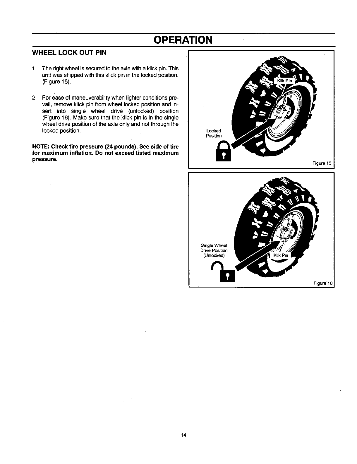
1. The right wheel is securedto the axle witha klick pin. This
unit was shipped with this klick pin in the locked position.
(Figure 15).
2, For ease of maneuverability when lighter conditions pre-
vail, remove klick pin from wheel locked position and in-
sert into single wheel drive (unlocked) position
(Figure 16). Make sure that the klick pin is in the single
wheel drive position of the axle only and not through the
locked position.
NOTE: Check tire pressure (24 pounds). See side of tire
for maximum inflation. Do not exceed listed maximum
pressure.
Locked
Positic)n
Figure 15
Single Wheel
Drive Position
(Unlocked)
Figure 16
14
OPERATION
BEFORE STARTING ENGINE 1.
Check the oil
NOTE: The engine was shipped from the factory filled
with oil. Check the level of the oil. Add oil as needed.
1. Make sure the unit is level. Use a high quality detergent
oil classified "For Service SG, SH, SJ, SL, or higher".
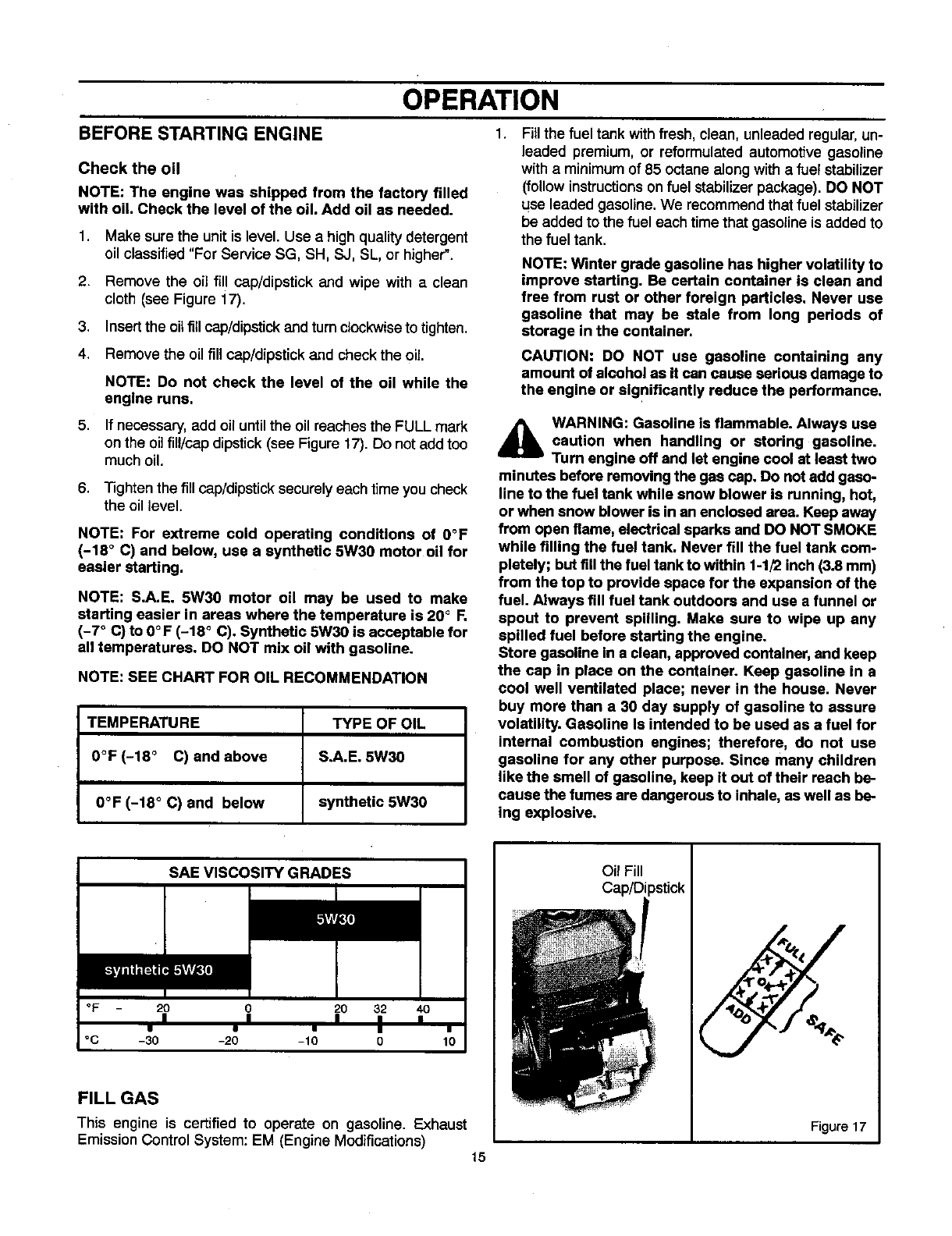
2. Remove the oil fill cap/dipstick and wipe with a clean
cloth (see Figure 17).
3. Insert the oil fill cap/dipstick and turn clockwiseto tighten.
4. Remove the oil fill cap/dipstick and check the oil
NOTE: Do not check the level of the oil while the
engine runs.
5. If necessary, add oil untilthe oil reaches the FULL mark
on the oil fill/cap dipstick (see Figure 17). Do not add too
much oil.
6. Tighten the fill cap/dipstick securelyeach time youcheck
the oil level.
NOTE: For extreme cold operating conditions of O°F
(-18 ° C) and below, use a synthetic 5W30 motor oil for
easier starting.
NOTE: S.A.E. 5W30 motor oil may be used to make
starting easier in areas where the temperature is 20 °F.
(-7 ° C) to 0°F (-18 °C). Synthetic 5W30 is acceptable for
all temperatures. DO NOT mix oil with gasoline.
NOTE: SEE CHART FOR OIL RECOMMENDATION
TEMPERATURE TYPE OF OIL
0°F (-18 °C) and above S.A.E. 5W30
0°F (-18 ° C) and below synthetic 5W30
Fillthe fuel tank withfresh, clean, unleaded regular, un-
leaded premium, or reformulated automotive gasoline
with a minimum of 85 octane along with a fuel stabilizer
(follow instructions on fuel stabilizer package). DO NOT
use leaded gasoline. We recommend that fuel stabilizer
be added to the fuel each time that gasoline is added to
the fuel tank.
NOTE: Winter grade gasoline has higher volatility to
improve starting. Be certain container is clean and
free from rust or other foreign particles. Never use
gasoline that may be stale from long periods of
storage in the container.
CAUTION: DO NOT use gasoline containing any
amount of alcohol as it can cause serious damage to
the engine or significantly reduce the performance.
,_ WARNING: Gasoline is flammable. Always use
caution when handling or storing gasoline.
Turn engine off and let engine cool at least two
minutes before removing the gas cap. Do not add gaso-
line to the fuel tank while snow blower is running, hot,
or when snow blower is in an enclosed area. Keep away
from open flame, electrical sparks and DO NOT SMOKE
while filling the fuel tank. Never fill the fuel tank com-
pletely; but fill the fuel tank to within 1-1/2 inch (3.8 mm)
from the top to provide space for the expansion of the
fuel. Always fill fuel tank outdoors and use a funnel or
spout to prevent spilling. Make sure to wipe up any
spilled fuel before starting the engine.
Store gasoline in a clean, approved container, and keep
the cap in place on the container. Keep gasoline in a
cool well ventilated place; never in the house. Never
buy more than a 30 day supply of gasoline to assure
volatility. Gasoline Is intended to be used as a fuel for
internal combustion engines; therefore, do not use
gasoline for any other purpose. Since many children
like the smell of gasoline, keep it out of their reach be-
cause the fumes are dangerous to inhale, as well as be-
ing explosive.
SAE VISCOSITY GRADES
°F 20 O 20 32 40
nn n , ,
• • •ii
°C -30 -20 -10 0 10
FILL GAS
This engine is certified 1o operate on gasoline, Exhaust
EmissionControl System: EM (Engine Modifications) 15
OilFill
%
Figure 17
OPERATION
BEFORE STOPPING THE ENGINE
Run the enginefor a few minutes to helpdry off any moisture
on the engine.
TO STOP ENGINE
CAUTION: To stop the engine, do not move the choke
control to CHOKE position. Backfire or engine damage
can occur.
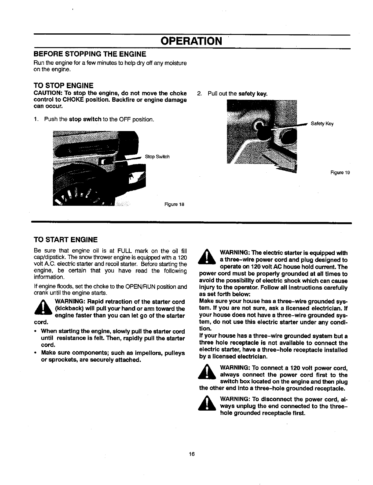
2. Pull out the safety key.
1. Push the stop switch to the OFF position.
Stop Switch
Saf_y Key
Figure 19
Figure 18
TO START ENGINE
Be sure that engine oil is at FULL mark on the oil fill
cap/dipstick. The snow thrower engine is equipped with a 120
volt A.C. electric starter and recoil starter. Before starting the
engine, be certain that you have read the following
information.
If engine floods, setthe choke to the OPEN/RUN position and
crank until the engine starts.
_lb WARNING: Rapid retraction of the starter cord
(kickback) will pull your hand or arm toward the
engine faster than you can let go of the starter
cord.
• When starting the engine, slowly pull the starter cord
until resistance is felt. Then, rapidly pull the starter
cord.
•Make sure components; such as Impellers, pulleys
or sprockets, are securely attached.
,_lb WARNING: The electric starter is equipped with
a three-wire power cord and plug designed to
operate on 120 volt AC house hold current. The
power cord must be properly grounded at all times to
avoid the possibility of electric shock which can cause
injury to the operator. Follow all instructions carefully
as set forth below:
Make sure your house has a three-wire grounded sys-
tem. If you are not sure, ask a licensed electrician. If
your house does not have a three-wire grounded sys-
tem, do not use this electric starter under any condi-
tion.
If your house has a three-wire grounded system but a
three hole receptacle is not available to connect the
electric starter, have a three-hole receptacle installed
by a licensed electrician.
_lb WARNING: T° connect a 120 volt power cord,
always connect the power cord first to the
switch box located on the engine and then plug
the other end into a three-hole grounded receptacle.
_lb WARNING: To disconnect the power cord, al-
ways unplug the end connected to the three-
hole grounded receptacle first.
16
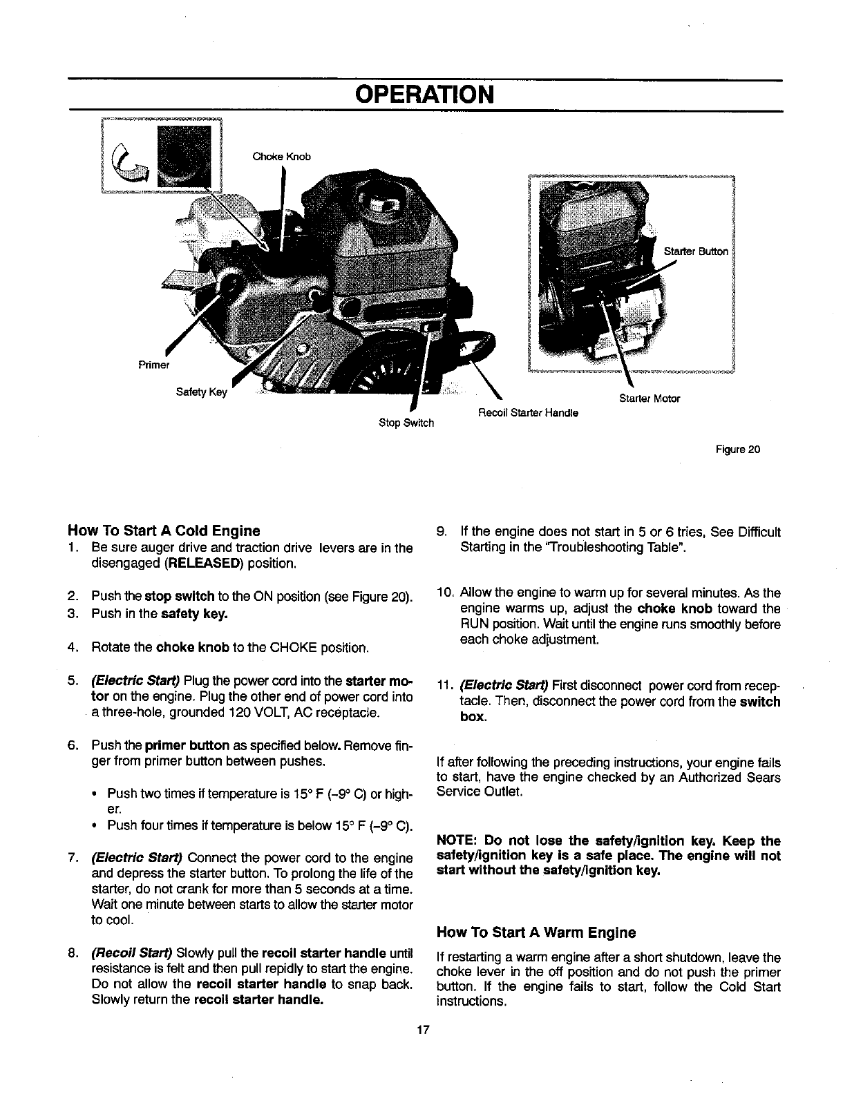
OPERATION
Choke Knob
Primer
Safety Key
Stop Switch Recoil Starter Handle
Starter Motor
Figure 20
How To Start A Cold Engine
1. Be sure auger drive and traction drive lovers are inthe
disengaged (RELEASED) position,
2. Push thestop switch to the ON position(see Figure20).
3. Push inthe safety key.
4. Rotate the choke knob to the CHOKE position.
5. (Electric Start) Plug the power cord intothe starter mo-
tor on the engine. Plug the other end of power cord into
a three-hole, grounded 120 VOLT, AC receptacle.
6. Push the primer button as specifiedbelow.Removefin-
ger from primer buttonbetween pushes.
•Push two times iftemperature is 15° F (-9°C) or high-
er.
• Push four times if temperature is below 15° F (-9 °C).
7, (Electric Start) Connect the power cord to the engine
and depress the starterbutton. To prolongthe lifeof the
starter, do not crank for more than 5 seconds at a time.
Wait one minute betweenstarts to allow the startermotor
to cool.
8, (Recoil Start) Slowly pull the recoil starter handle until
resistanceis felt and then pullrepidlyto startthe engine.
Do not allow the recoil starter handle to snap back.
Slowly returnthe recoil starter handle.
9. If the engine does not start in 5 or 6tries, See Difficult
Starting in the 'q'roubleshooting Table".
10. Allowthe engine to warm upfor several minutes. As the
engine warms up, adjust the choke knob toward the
RUN position. Wait until the engine runs smoothly before
each choke adjustment.
11. (Electric Start) First disconnect power cordfrom recep-
tacle. Then, disconnectthe power cord from the switch
box.
If after following the preceding instructions,your engine fails
to start, have the engine checked by an Authorized Sears
Service Outlet.
NOTE: Do not lose the safety/ignition key, Keep the
safety/ignition key is a safe place. The engine will not
start without the safety/ignition key.
How To Start A Warm Engine
If restarting a warm engine after a short shutdown,leave the
choke lever in the off position and do not push the primer
button. If the engine fails to start, follow the Cold Start
instructions.
17
OPERATION
FROZEN STARTER
If the starter is frozen and will not turn engine:
1 Pull as muchrope out of the starteras possible.
2. Release the starter handle and let it snap back against
the starter. Repeat until the engine starts.
Warm engines will cause condensation in cold weather, To
help prevent possible freeze-up of recoil starter and engine
controls, proceed as follows after each snow removal job.
1. With engine off, allow engine to cool for several minutes.
2. Pull starter rope very slowly until resistance is felt, then
stop. Allow the starter rope to recoil. Repeat three times.
3. With the engine not running, wipe all snow and moisture
from the carburetor cover in area of control levers. Also
move choke knob and starter handle several times.
,_ WARNING: Never run engine indoors or in en-
closed, poorly ventilated areas. Engine exhaust
contains CARBON MONOXIDE, AN ODORLESS
AND DEADLY GAS. Keep hands, feet, hair and loose
clothing away from any moving parts on engine and
snow thrower.
• Engine parts, especially the muffler, become ex-
tremely hot. Severe thermal burns can occur on con-
tact. Allow the engine to cool before touching.
• Never allow children to operate the snow thrower.
Never allow adults to operate the snow blower with-
out proper instruction.
•Keep the area of operation clear of all persons, partic-
ularly small children and pets.
•Never leave the snow blower unattended while the
engine Is running. Anyone opersting the engine or
equipment must carefully read and understand the
operating instructions.
IMPORTANT: After each use of the snow blower, stop the
engine, remove the safety/ignition key, remove all
accumulated snow from the snow blower and wipe
clean. Store the snow blower in a protected area.
NOTE: Never cover snow blower while engine and
exhaust area ere still warm.
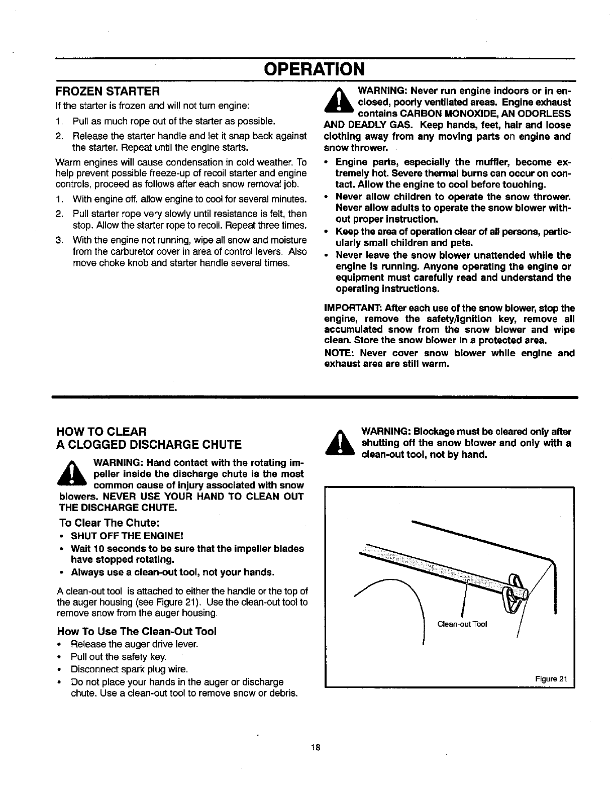
HOW TO CLEAR
A CLOGGED DISCHARGE CHUTE
_k WARNING: Hand contact with the rotating im-
peller inside the discharge chute is the most
common cause of injury associated with snow
blowers. NEVER USE YOUR HAND TO CLEAN OUT
THE DISCHARGE CHUTE.
To Clear The Chute:
•SHUT OFF THE ENGINEI
•Wait 10 seconds to be sure that the impeller blades
have stopped rotating.
•Always use a clean-out tool, not your hands.
A clean-out tool is attached to either the handle or the top of
the auger housing (see Figure 21). Use the clean-out toot to
remove snow from the auger housing.
How To Use The Clean-Out Tool
•Release the auger drive lever.
•Pull out the safety key.
Disconnect spark plug wire.
Do not place your hands inthe auger or discharge
chute. Use a clean-outtool to remove snow or debris.
AWARNING: Blockage must be cleared only after
shutting off the snow blower and only with a
clean-out tool, not by hand.
Clean-out Tool
Figure 21
18
OPERATION
OPERATING TIPS
1. Most efficient snowblowingis accomplished when snow 6.
is removed immediately after it falls.
2. For complete snow removal, slightly overlap each swath
previously taken. 7.
3. Snow should be discharged downwind whenever pos-
sible. 8.
4. For normal usage, set the skids one-eighth inch (3 mm)
below the scraper bar. For extremely hard-packed snow
surfaces, the skids may be adjusted upward to insure
cleaning efficiency.
5. On gravel or crushed rock surfaces, the skids should be
set at 1-1/4 inch (32 mm) below the scraper bar (see To
Adjust Skid Height, in the Adjustment/Repair section in
this manual). Rocks and gravel must not be picked up
and thrown by the machine.
After the snowblowing job has been completed, allow the
engine to idle far a few minutes, to melt snow and ice ac-
cumulated on the engine.
Clean the snow thrower thoroughly after each use.
Remove ice and snow accumulation and all debris from
the entire snow thrower, and flush with water ('ifpossible)
to remove all salt or other chemicals. Wipe snow thrower
dry.
9.
10.
Before starting snow blower, always inspect augers and
impeller for ice accumulation and/or debris, which could
result in snow blower damage.
Check oil level before every start. Make sure the oil is at
the FULL mark on the oil fill cap/dipstick.
19
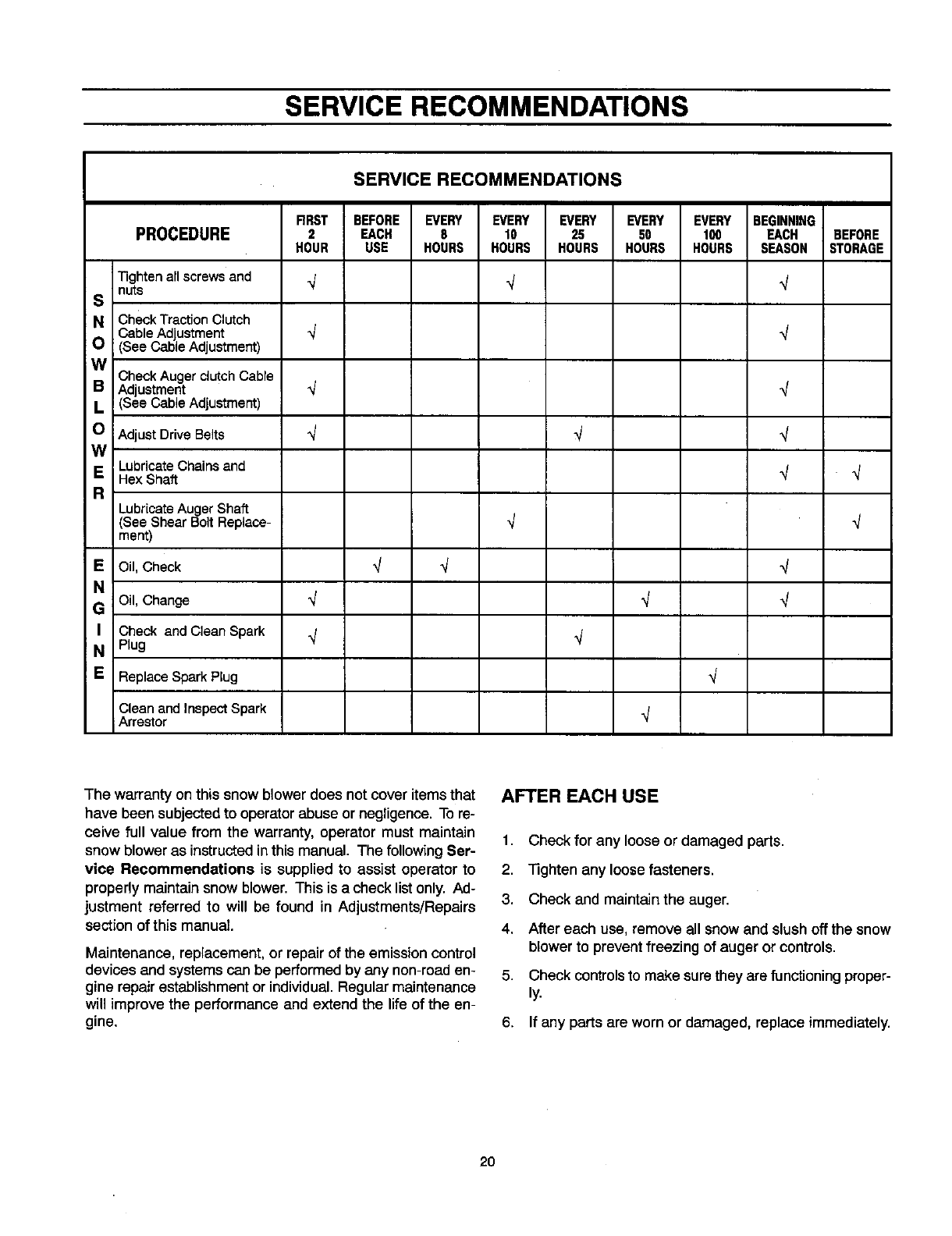
SERVICE RECOMMENDATIONS
SERVICE RECOMMENDATIONS
RRST BEFORE EVERY EVERY EVERY EVERY EVERY BEGINNING
PROCEDURE 2 EACH 8 10 25 50 t00 EACH BEFORE
HOUR USE HOURS HOURS HOURS HOURS HOURS SEASON STORAGE
Tightenallscrewsand _/ _/ _/
Snuts
NCheck TractionClutch
Cable Ad ustment _/ _/
O (SeeCab eAd ustment)
;_l Check Auger clutch Cable
Adustment "_
(SeeCab e Adustmerrt)
OAdjustDriveBelts _ _ _/
W
ELubricateChainsand
HexShaft "J "_
RLubricateAuger Shaft
(SeeShear Bolt Replace-
ment)
EOil, Check _J
N
GOil, Change "_
ICheck and Clean Spark
NPlug
E Replace Spark Plug
q
,/
.j
,J
,/
,J
Clean and Inspect Spark
Arrestor q
The warranty on this snow blower does not cover items that
have been subjected to operator abuse or negligence. To re-
ceive full value from the warranty, operator must maintain
snow blower as instructed in this manual. The following Ser-
vice Recommendations is supplied to assist operator to
properly maintain snow blower. This is a check list only. Ad-
justment referred to will be found in Adjustments/Repairs
section of this manual.
Maintenance, replacement, or repair of the emission control
devices and systems can be performed by any non-road en-
gine repair establishment or individual. Regular maintenance
will improve the performance and extend the life of the en-
gine.
AFTER EACH USE
1. Check for any loose or damaged parts.
2. "]]ghten any loose fasteners.
3. Check and maintain the auger.
4. After each use, remove all snow and slush off the snow
blower to prevent freezing of auger or controls.
5. Check controls to make sure they are functioning proper-
ly.
6. If any parts are worn or damaged, replace immediately.
20
CUSTOMER RESPONSIBILITIES
Some adjustments will need to be made periodically to
properly maintain your snow blower.
All adjustments in ADJUSTMENTS/REPAIRS section of this
manual should be checked at least once each season.
SNOW BLOWER
The following adjustment should be performed more than
once each season.
Auger and Traction Drive Belts should be adjustedafterthe
first 2 to 4 hours of use, again about mid-season and twice
each seasonthereafter(See ToAdjustBeltsparagraphinthe
Adjustment/Repair section).
AS REQUIRED
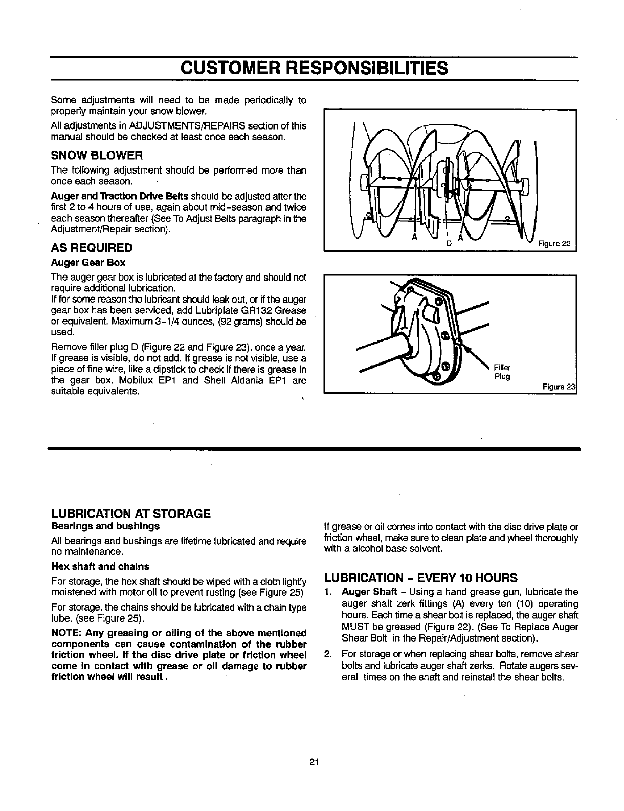
Auger Gear Box
The auger gear box is lubricatedat the factory and shouldnot
require additional lubrication.
If for some reason the lubdcantshould leak out, or if the auger
gear box has been serviced, add Lubriplate GR132 Grease
or equivalent. Maximum 3-1/4 ounces, (92 grams) should be
used.
Remove filler plug D (Figure 22 and Figure 23), once a year.
If grease is visible, do not add. If grease is not visible, use a
piece of fine wire, like a dipstick to check if there is grease in
the gear box. Mobilux EP1 and Shell Aldania EP1 are
suitable equivalents.
D Figure 22
_ FiUer
Plug
Figure 23
LUBRICATION AT STORAGE
Bearings and bushings
All bearingsand bushingsare lifetimelubricatedand require
no maintenance.
Hex shaft and chains
For storage, the hex shaft should be wipedwitha cloth lightly
moistened with motor oil to prevent rusting (see Figure 25),
For storage, the chains should be lubricated with a chain type
lube. (see Figure 25).
NOTE: Any greasing or oiling of the above mentioned
components can cause contamination of the rubber
friction wheel. If the disc drive plate or friction wheel
come in contact with grease or oil damage to rubber
friction wheel will result.
if grease oroil comes intocontactwith the disc drive plate or
friction wheel, make sure to clean plate and wheelthoroughly
with a alcohol base solvent.
LUBRICATION -EVERY 10 HOURS
1. Auger Shaft - Using a hand grease gun, lubricate the
auger shaft zerk fittings (A) every ten (10) operating
hours. Each time a shearboltis replaced,the auger shaft
MUST be greased (Figure 22). (See To Replace Auger
Shear Bolt inthe Repair/Adjustmentsection).
2. For storage or when replacing shear bolts,remove shear
bolts and lubricate auger shaft zerks. Rotate augers sev-
eral times on the shaft and reinstall the shear bolts.
21
CUSTOMER RESPONSIBILITIES
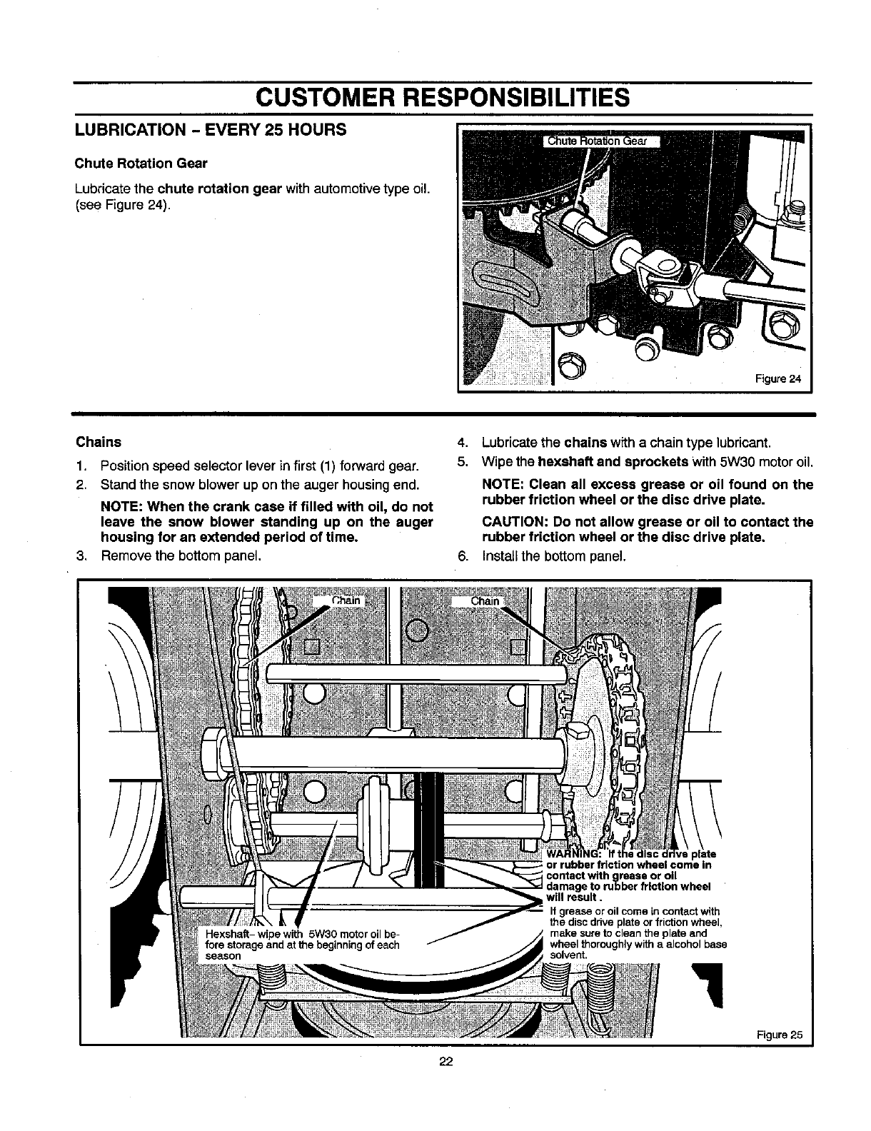
LUBRICATION -EVERY 25 HOURS
Chute Rotation Gear
Lubricate the chute rotation gear withautomotive type oil.
(see Figure 24).
Figure 24
Chains
1. Position speed selector lever in first (1) forward gear.
2. Stand the snow blower up on the auger housing end.
NOTE: When the crank case if filled with oil, do not
leave the snow blower standing up on the auger
housing for an extended period of time.
3. Remove the bottom panel.
4. Lubricatethe chains w_tha chain type lubricant.
5. Wipe the hexahaft and sprockets With 5W30 motor oil.
NOTE: Clean all excess grease or oil found on the
rubber friction wheel or the disc drive plate.
CAUTION: Do not allow grease or oil to contact the
rubber friction wheel or the disc drive plate.
6. Install the bottom panel.
) in
contact withn_llrease or oil
damage to rubber friction wheel
will result.
If grease or oil come in contact with
the discdrive plate or frictionwheel,
make sure to clean the plate and
wheel thoroughlywith a alcohol base
solvent,
Figure 25
22
CUSTOMER RESPONSIBILITIES
ENGINE
POWER RATINGS
The power ratings for an individualengine model are initially
developed by starting with SAE (Society of Automotive
Engineers) code J1940 (Small Engine Power & Torque
Rating Procedure) (Revision 2002-05). Given both the wide
array of products on which our engines are placed, and the
variety of environmental issues applicable to operating the
equipment, it may be that the engine you have purchased will
not develop the rated horsepower when used in a piece of
power equipment (actual "on-site" power). This difference is
due to a variety of factors including, but not limited to, the
following: differences in altitude, temperature, barometric
pressure, humidity, fuel, engine lubrication, maximum
governed engine speed, individual engine to engine
variability, design of the particular piece of power equipment,
the manner in which the engine is operated, engine run-in to
reduce friction and clean out of combustion chambers,
adjustments to the valves and carburetor, and other factors.
The power ratings may also be adjusted based on
comparisons to other similar engines utilized in similar
applications, and will therefore not necessarily match the
values derived using the foregoing codes.
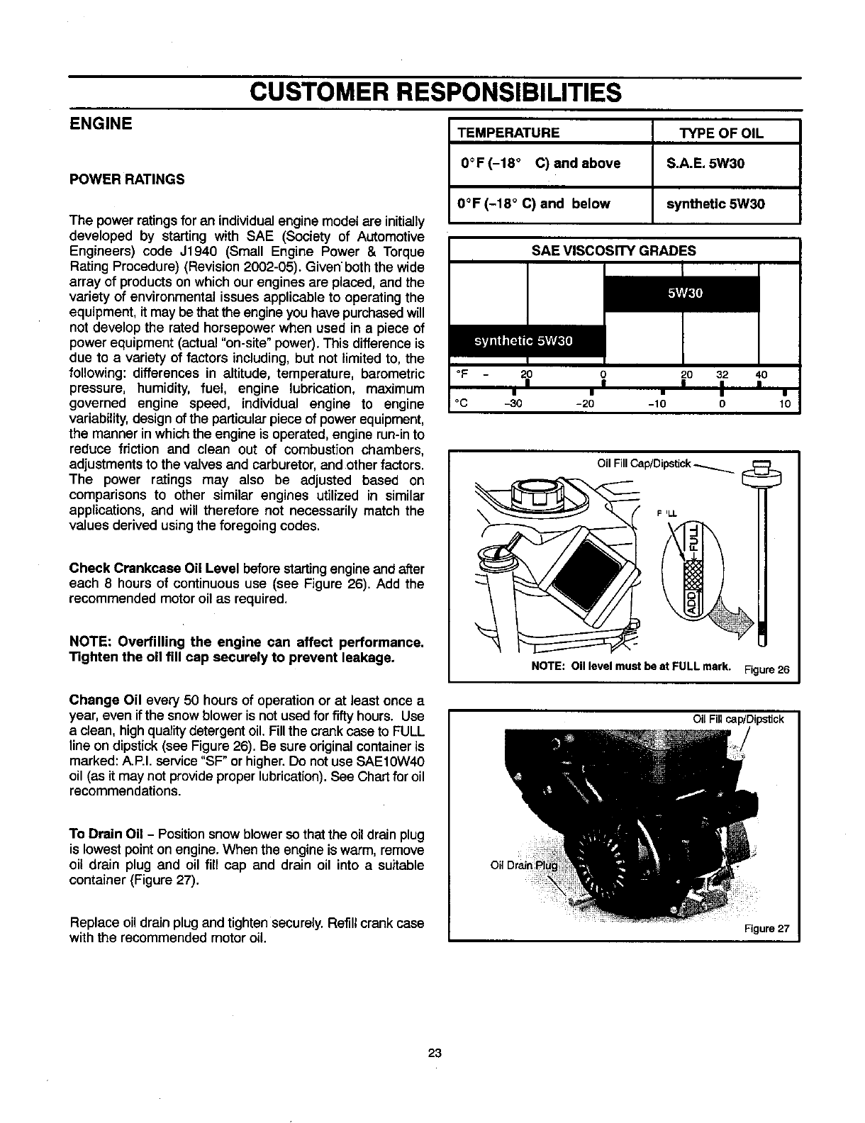
Check Crankcase Oil Level before startingengine and after
each 8 hours of continuous use (see Figure 26). Add the
recommended motor oil as required.
NOTE: Overfilling the engine can affect performance.
Tighten the oil fill cap securely to prevent leakage.
TEMPERATURE TYPE OF OIL
0°F (-18 ° C) and above S.A.E. 5W30
0°F (-18 ° C) and below synthetic 5W30
SAE VlSCosrrY GRADES
°F 20 O 20 32 40
I I • I I
°C -30 -20 -10 0 10
Oil Fill Cap/Dipstick _
F_LL
NOTE: Oil level must be at FULL mark. -,_=;_ure26
Change Oil every 50 hours of operation or at least once a
year. even if the snowblower is not used for fifty hours, Use
a clean, highqualitydetergentoil.Fillthe crankcase to FULL
line on dipstick(see Figure 26). Be sure originalcontaineris
marked: A.P.I. service"SF" or higher.Do not use SAE10W40
oil (as it may notprovide properlubrication).See Chartfor oil
recommendations.
To Drain Oil -Positionsnowblower so that the oil drain plug
is lowest pointon engine. When the engine is warm, remove
oil drain plug and oil fill cap and drain oil into a suitable
container (Figure 27).
Replace oil drain plug and tighten securely. Refill crank case
with the recommended motor oil.
Oil Fillcap/Dipslick
Figure 27
23
ADJUSTMENT/REPAIR
4_lb WARNING: Always turn unit off, remove igni-
tion key and disconnect the spark plug wire be-
fore making any repairs or adjustments.
AUGER HOUSING HEIGHT ADJUSTMENT
TO ADJUST SCRAPER BAR
After considerable use, the metal scraper bar will have a
definite wear pattern. The scraper bar in conjunction with the
skids should always be adjusted to allow one-eighth of an
inch (3 mm) between the scraper bar and the sidewalk or
area to be cleaned.
To adjust the scraper bar, proceed as follows:
1. Position the snow blower on a level surface.
2,
3.
4,
Loosen the carriage bolts and nuts securing the scraper
bar to the auger housing.
Adjust the scraper bar to the proper position. "l]ghten the
carriage bolts and nuts, insuring that the scraper bar is
parallel with the working surface.
For extended operation, the scraper bar may be re-
versed. If the scraper bar must be replaced because of
wear, remove the carriage bolts and nuts and install a
new scraper bar.
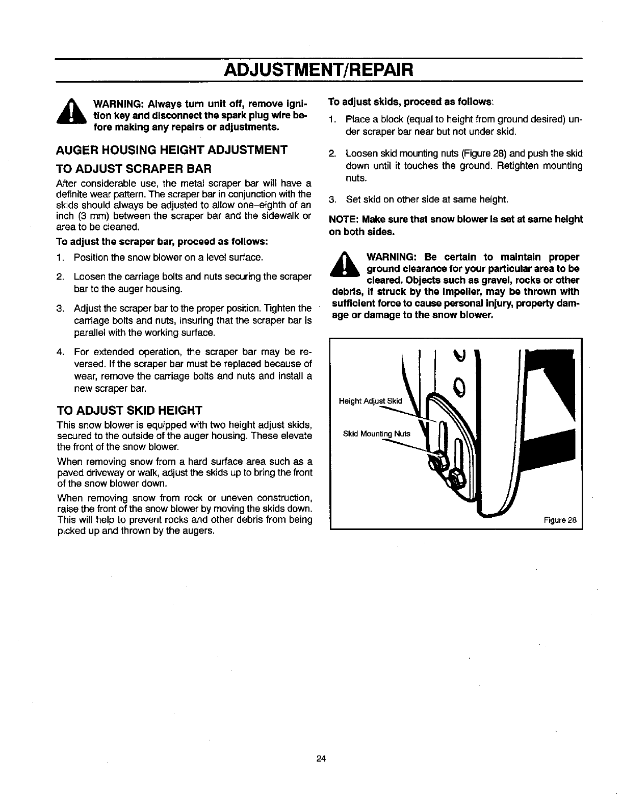
TO ADJUST SKID HEIGHT
This snow blower is equipped withtwo height adjust skids,
secured to the outside of the auger housing. These elevate
the front of the snow blower.
When removing snow from a hard surface area such as a
paved driveway or walk, adjust the skids up to bring the front
of the snow blower down.
When removing snow from rock or uneven construction,
raise the front of the snow blower by moving the skids down.
This will help to prevent rocks and other debris from being
picked up and thrown by the augers.
To adjust skids, proceed as follows:
1. Place a block (equal to height from ground desired) un-
der scraper bar near but not under skid.
2. Loosen skid mounting nuts (Figure 28) and push the skid
down until it touches the ground. Retighten mounting
nuts.
3. Set skid on other side at same height.
NOTE: Make sure that snow blower is set at same height
on both sides.
,_ WARNING: Be certain to maintain proper
ground clearance for your particular area to be
cleared. Objects such as gravel, rocks or other
debris, if struck by the impeller, may be thrown with
sufficient force to cause personal injury, property dam-
age or damage to the snow blower.
Height Adjust Skid
Skid Mounting Nuts
Figure 28
24
ADJUSTMENT/REPAIR
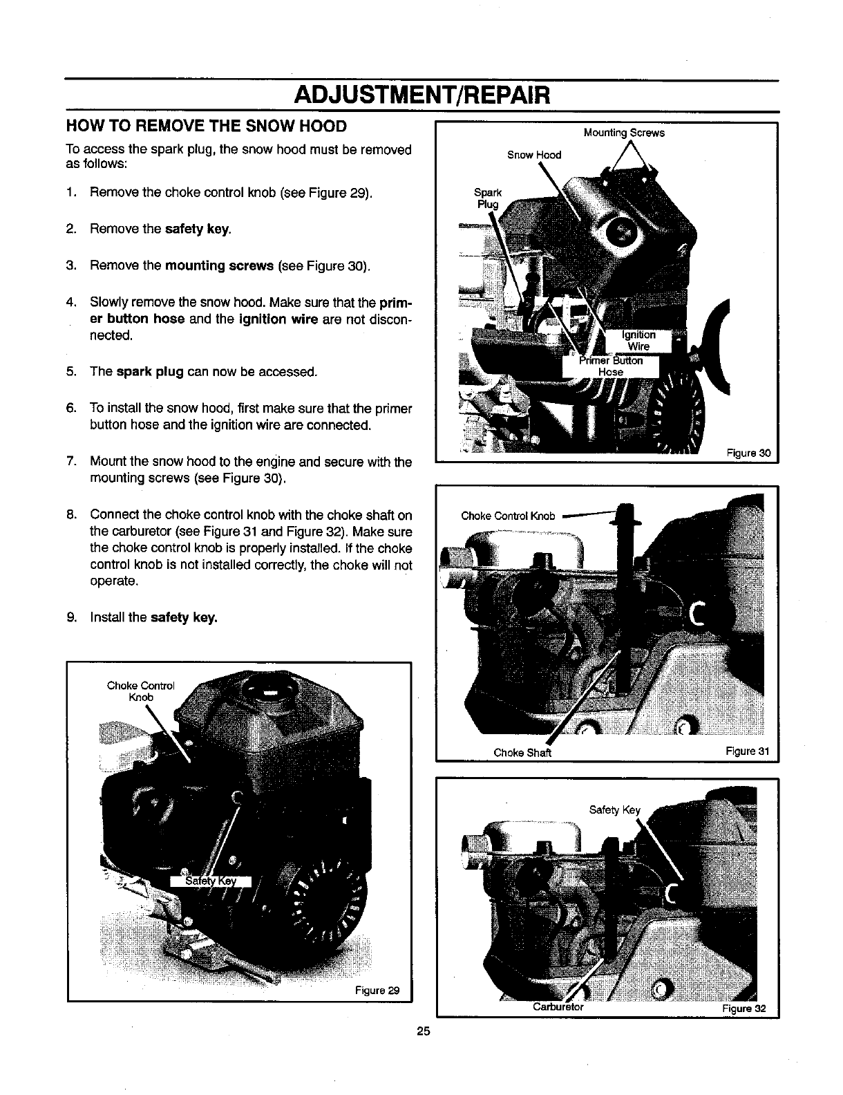
HOW TO REMOVE THE SNOW HOOD
To access the spark plug, the snow hood must be removed
as follows:
1. Remove the choke control knob (see Figure 29).
2. Remove the safety key.
3. Remove the mounting screws (see Figure 30).
4. Slowly remove the snowhood. Make surethat the prim-
er button hose and the ignition wire are not discon-
nected.
5. The spark plug can now be accessed.
6. To installthe snow hood,first make surethat the primer
buttonhose and the ignitionwire are connected.
7. Mountthe snow hoodto the engine and secure with the
mountingscrews (see Figure 30).
Mounting Screws
Snow Hood
Spark
Plug
Figure 30
8. Connect the choke controlknob withthe choke shaft on
the carburetor(see Figure 31 and Figure 32). Make sure
the choke controlknob is properlyinstalled. If the choke
control knob is not installed correctly,the choke will not
operate.
9. Install the safety key.
Choke Control
Knob
Figure 29
Choke Shaft Figure 31
Safety Key
Carburetor Figure 32
25
ADJUSTMENT/REPAIR
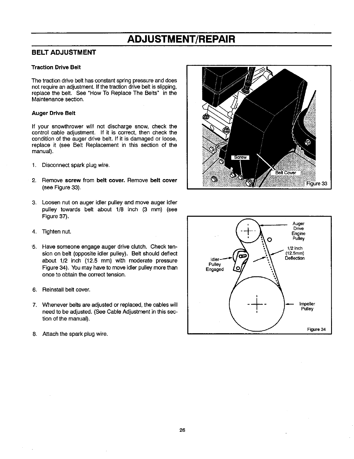
BELT ADJUSTMENT
Traction Drive Belt
The traction drive belt has constant spring pressure and does
not require an adjustment. If the traction drive belt is slipping,
replace the belt. See "How To Replace The Belts" in the
Maintenance section.
Auger Drive Belt
If your snowthrower will not discharge snow, check the
control cable adjustment. If it is correct, then check the
condition of the auger drive belt. If it is damaged or loose,
replace it (see Belt Replacement in this section of the
manual).
1. Disconnect spark plug wire.
2.
3,
4,
'5.
6,
7.
Remove screw from belt cover. Remove belt cover
(see Figure 33),
Loosen nut on auger idler pulley and move auger idler
pulley towards belt about 1/8 inch (3 mm) (see
Figure 37).
Tighten nut.
Have someone engage auger drive clutch. Check ten-
sion on belt (opposite idler pulley). Belt should deflect
about 1/2 inch (12.5 mm) with moderate pressure
Figure 34). You may have to move idler pulley more than
once to obtain the correct tension.
Reinstall belt cover.
Whenever belts are adjusted or replaced, the cables will
need to be adjusted. (See Cable Adjustment inthis sec-
tion of the manual).
8. Attach the spark plug wire.
Auger
Ddve
Engine
OPulley
1/2 inch
(12.5mm)
Deflection
Idler
Pulley
Engaged 1-
Impeller
Pulley
Figure 34
26
ADJUSTMENT/REPAIR
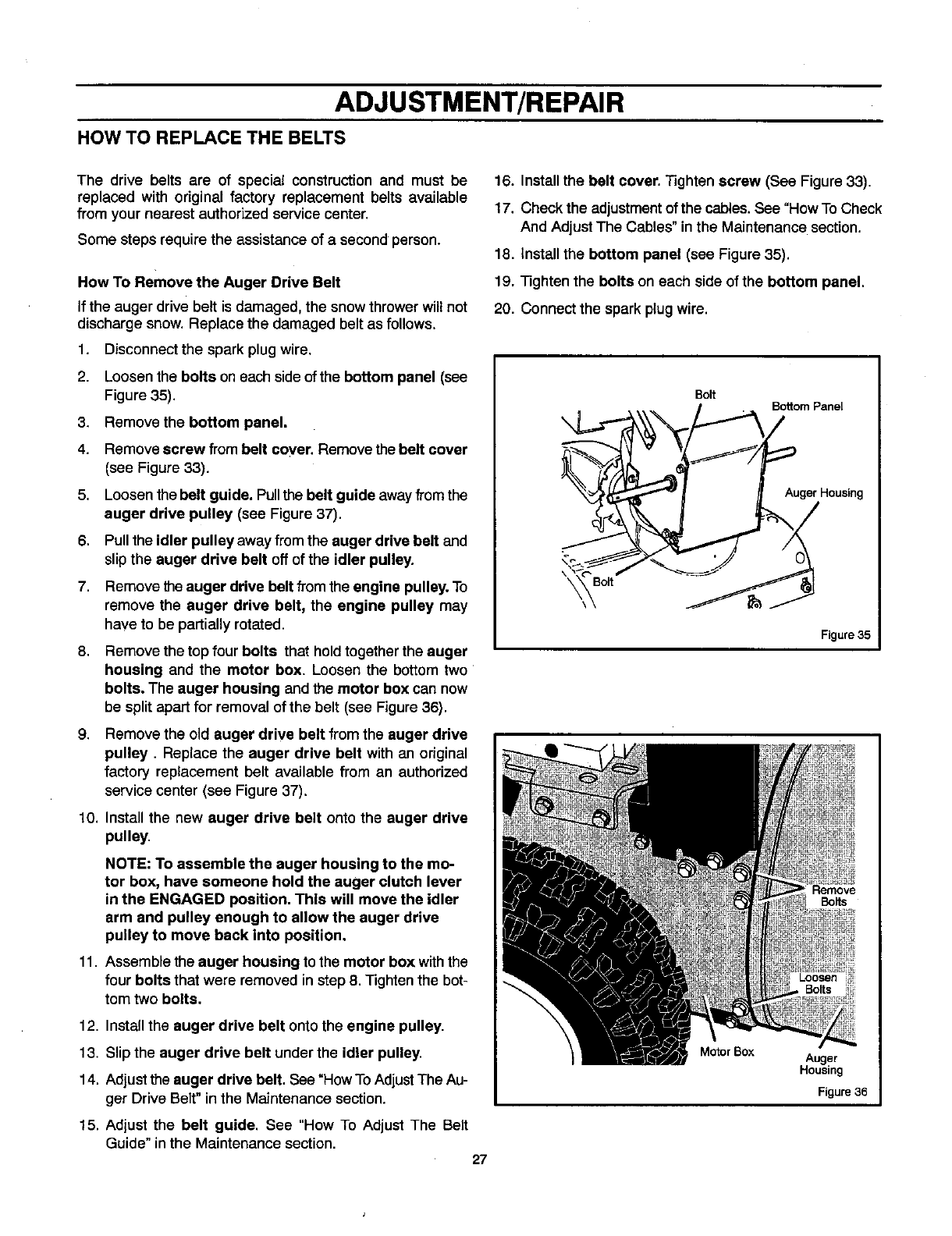
HOW TO REPLACE THE BELTS
The drive belts are of special construction and must be
replaced with original factory replacement belts available
from your nearest authorized service center.
Some steps require the assistance of a second person.
How To Remove the Auger Drive Belt
If the auger drive belt is damaged, the snowthrowerwill not
discharge snow. Replace the damaged belt as follows.
1. Disconnect the spark plug wire.
2. Loosen the bolts on each side ofthe bottom panel (see
Figure 35).
Remove the bottom panel.
Remove screw from belt coyer. Remove the belt cover
(see Figure 33).
3,
4.
5.
6.
7.
Loosen the belt guide. Pull the belt guide awayfrom the
auger drive pulley (see Figure 37).
Pullthe idler pulley away from the auger drive belt and
slipthe auger drive belt off of the idler pulley.
Remove the auger drive belt from the engine pulley. To
remove the auger drive belt, the engine pulley may
have to be partially rotated.
8. Remove the top four bolts that holdtogetherthe auger
housing and the motor box. Loosen the bottom two
bolts. The auger housing and the motor box can now
be split apart for removal of the belt (see Figure 36).
9, Remove the old auger drive belt from the auger drive
pulley. Replace the auger drive belt with an original
factory replacement belt available from an authorized
service center (see Figure 37).
10. Install the new auger drive belt onto the auger drive
pulley.
NOTE: To assemble the auger housing to the mo-
tor box, have someone hold the auger clutch lever
in the ENGAGED position, This will move the idler
arm and pulley enough to allow the auger drive
pulley to move back into position.
11. Assemble the auger housing to the motor box withthe
four bolts that were removed in step 8. Tightenthe bot-
tom two bolts.
12. Installthe auger drive belt onto the engine pulley.
13. Slip the auger drive belt under the idler pulley.
14. Adjust the auger drive belt. See "How ToAdjust The Au-
ger Drive Belt"in the Maintenance section.
15. Adjust the belt guide. See "How To Adjust The Belt
Guide"inthe Maintenance section. 27
16. Install the belt cover. Tighten screw (See Figure 33).
17. Check the adjustmentof the cables.See "How ToCheck
And AdjustThe Cables" in the Maintenance section.
18. Install the bottom panel (see Figure 35).
19. Tighten the bolts on each side of the bottom panel.
20. Connect the spark plugwire.
\
Bolt Bottom Panel
Auger Housing
Bolt
Figure 35
Bolts
Motor Box Auger
Housing
Figure 36
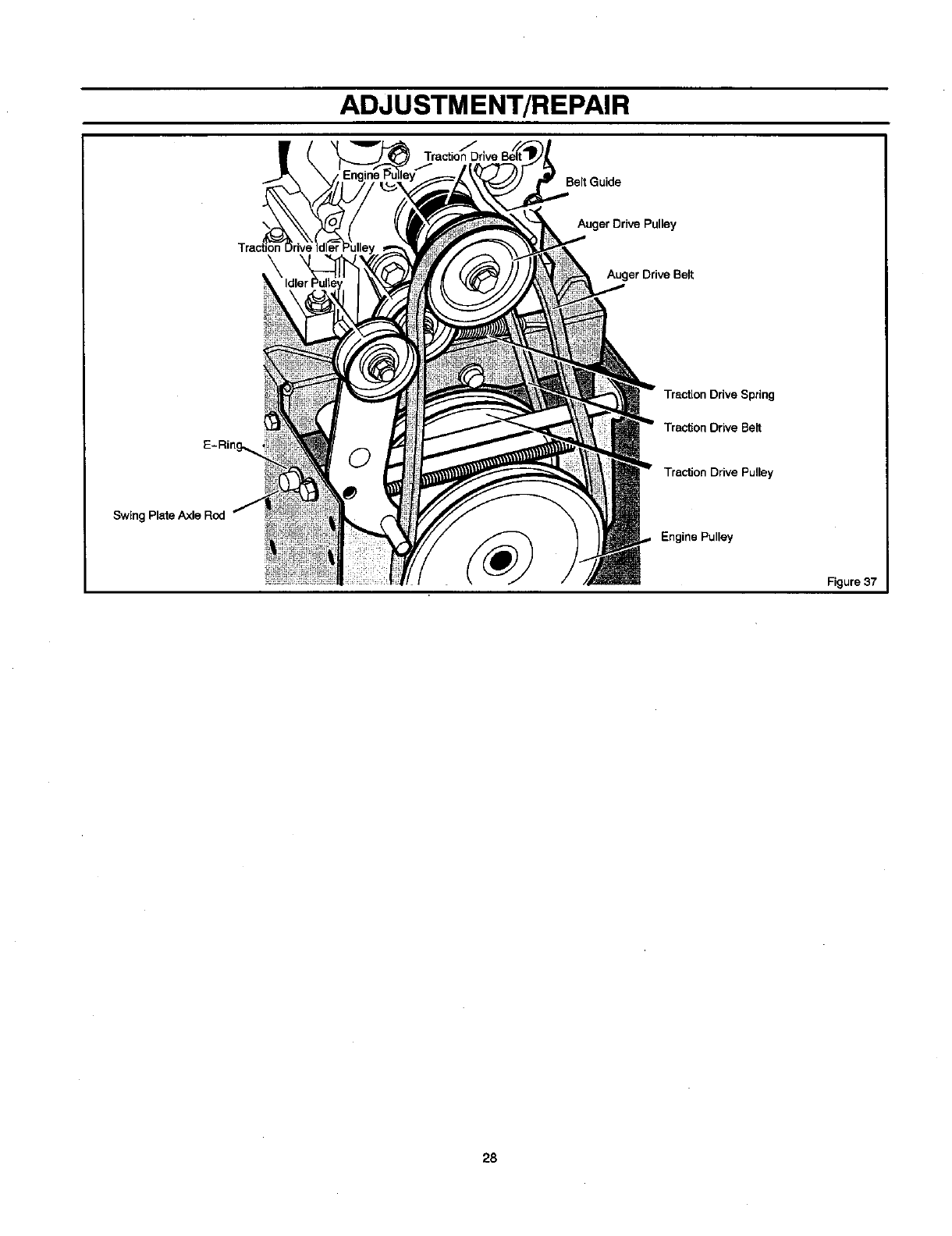
ADJUSTMENT/REPAIR
Swing Plate Axle Red
Belt Guide
Auger Drive Pulley
Auger Drive Belt
Traction Drive Spring
Traction Drive Belt
Traction Drive Pulley
Engine Pulley
Figure 37
28
ADJUSTMENT/REPAIR
How To Remove the Traction Drive Belt
If the snow thrower will not move forward, check the traction
drive belt for wear or damage. Ifthe traction drive belt is worn
or damaged, replace the belt as follows.
1, Disconnect the spark plug wire.
2. Remove the auger drive belt. See "How To Remove The
Auger Drive Belt" in the Maintenance section.
11. Install and adjust the auger drive belt. See "How To Re-
move The Auger Drive Belt" in the Maintenance section.
12. Adjust the belt guide. See "How To Adjust The Belt
Guide"inthe Maintenance section.
13. Install the bottom panel (see Figure 35).
3, Remove the e-ring from one end of the swing plate
axle rod. Remove the swing plate axle rod to allowthe
the swing plateto pivotforward (see Figure 37).
14. Tighten the bolts on each side of the bottom panel.
15, Install the belt cover, Tighten screw (see Figure 33).
4.
5.
Remove the traction drive spring.
Remove the aid traction drive belt from the traction
drive pulley and from the engine pulley. Replace the
traction drive belt with an originalfactory replacement
belt available from an authorized service center.
16. Check the adjustment of the cables. See "How To Check
And Adjust The Cables" in the Maintenance section.
17. Connect the spark plug wire.
6,
7.
Install the new traction drive belt onto the traction
drive pulley and onto engine pulley.
Make sure the traction drive Idler pulley is properly
aligned withthe traction drive belt.
8. Attach the traction drive spring.
9. Installthe swing plate axle rod and secure withthe e-
ring removed earlier.
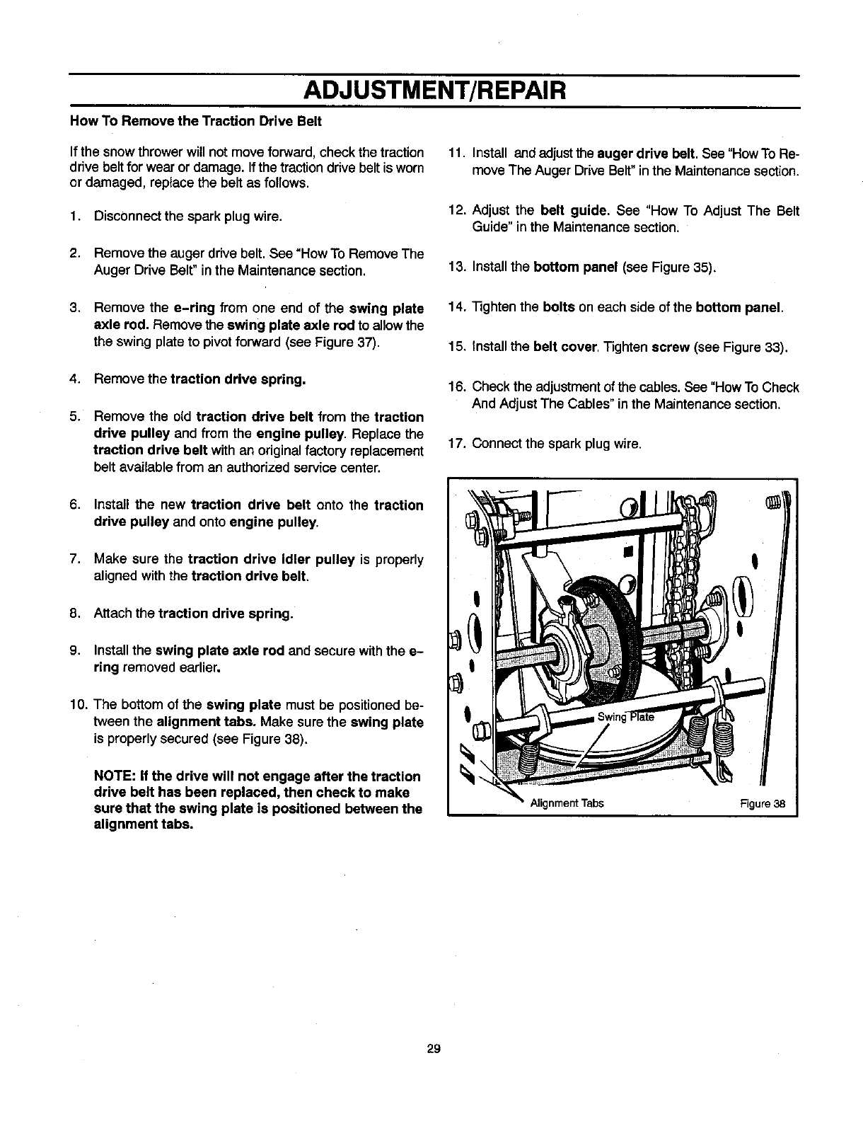
10. The bottom of the swing plate must be positioned be-
tween the alignment tabs. Make sure the awing plate
is properlysecured (see Figure 38).
NOTE: If the drive will not engage after the traction
drive belt has been replaced, then check to make
sure that the swing plate is positioned between the
alignment tabs.
Alignment Tabs Figure 38
29
ADJUSTMENT/REPAIR
BELT GUIDE ADJUSTMENT
1. Remove spark plug wire.
2. Have someone engage auger drive.
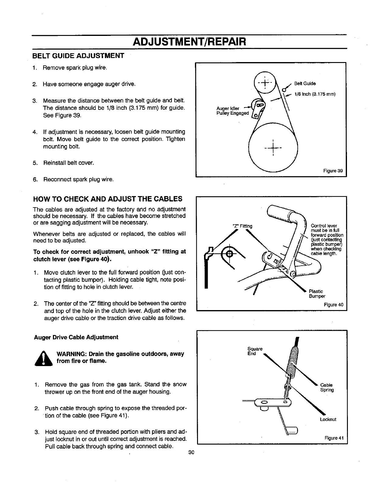
3. Measure the distance between the belt guide and belt.
The distance should be 1/8 inch (3.175 mm) for guide.
See Figure 39.
4. If adjustment is necessary, loosen belt guide mounting
bolt. Move belt guide to the correct position. "Nghten
mounting bolt.
5. Reinstall belt cover.
._ O_ BeltGuide
ed_ Figure 39
6. Reconnect spark plug wire.
HOW TO CHECK AND ADJUST THE CABLES
The cables are adjusted at the factory and no adjustment
should be necessary. If the cables have become stretched
or are sagging adjustment will be necessary.
Whenever belts are adjusted or replaced, the cables will
need to be adjusted.
To check for correct adjustment, unhook "Z" fitting at
clutch lever (see Figure 40).
1. Move clutch lever to the full forward position (just con-
tacting plastic bumper). Holding cable tight, note posi-
tion of fitting to hole in clutch lever.
2. The center of the "Z" fitting should be between the centre
and top of the hole in the clutch lever. Adjust either the
auger drive cable or the traction drive cable as follows.
"Z" Fitting Control lever
must be infull
forward pos_on
(just contacting
plastic bumper)
when checking
cable length.
Plastic
Bumper
Figure 40
Auger Drive Cable Adjustment
_lb ARNING: Drain the gasoline outdoors, away
from fire or flame,
1. Remove the gas from the gas tank. Stand the snow
thrower up on the front end of the auger housing.
2. Push cable through spring to expose the threaded por-
tion of the cable (see Figure 41).
3. Hold square end of threaded portion withpliers and ad-
just Iocknut in or out until correct adjustment is reached.
Pull cable back through spring and connect cable. 30
Square
End \
Cable
Spring
Locknut
Figure 41
ADJUSTMENT/REPAIR
Traction Drive Cable Adjustment
,_ WARNING: Drain the gasoline outdoors, awayfrom fire or flame.
1. Remove the gas from the gas tank. Stand the snow
thrower up on the front end of the auger housing.
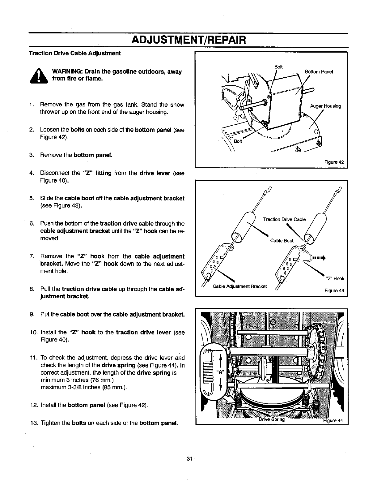
2. Loosen the bolts on each side of the bottom panel (see
Figure 42).
3. Remove the bottom panel,
\
Bolt Boffom Panel
Auger Housing
4. Disconnect the "Z" fitting from the drive lever (see
Figure 40).
5.
6,
Slide the cable boot off the cable adjustment bracket
(see Figure 43).
Push the bottom of the traction drive cable through the
cable adjustment bracket untilthe "Z" hook can be re-
moved.
7. Remove the "Z" hook from the cable adjustment
bracket. Move the "Z" hook down to the next adjust-
ment hole.
8. Pull the traction drive cable up throughthe cable ad-
justment bracket,
Traction Drive Cable
\
Cable Boot
)IIKII_
Cable Adjustment Bracket
Figure42
"Z" Hook
Figure 43
9. Put the cable boot over the cable adjustment bracket.
10. Install the "Z" hook to the traction drive lever (see
Figure 40).
11. To check the adjustment, depress the drive lever and
check the length of the drive spring (see Figure 44). In
correct adjustment, the lengthof the drive spring is
minimum3 inches (76 mm.)
maximum 3-3/8 inches (85 mm.).
12. Installthe bottom panel (see Figure 42),
13. Tighten the bolts on each side of the bottom panel. Figure 44
31
ADJUSTMENT/REPAIR
5. Tighten the jam nut.
HOW TO ADJUST OR REPLACE
THE FRICTION WHEEL
How To Check The Friction Wheel 6. Install the bottom panel (see Figure 45).
If the snowthrower will not move forward, check the traction
drive belt, the traction drive cable or the friction wheel. Ifthe
friction wheel is worn or damaged, it must be replaced. See
=How To Replace the Friction Wheel" in this section. If the
friction wheel is not worn or damaged, check as follows.
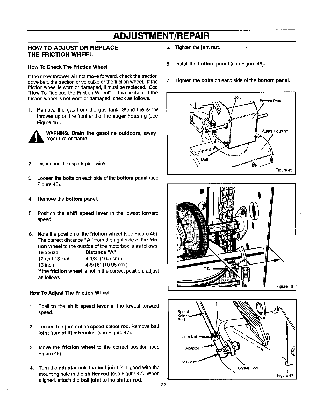
1. Remove the gas from the gas tank. Stand the snow
thrower up on the front end of the auger housing (see
Figure 45).
,_ WARNING: Drain the gasoline outdoors, away
from fire or flame,
2,
3.
4.
5.
6.
Disconnect the spark plug wire.
Loosenthe bolts on each side of the bottom panel (see
Figure 45).
Remove the bottom panel.
Position the shift speed lever in the lowest forward
speed.
Note the position of the friction wheel (see Figure 46).
The correct distance "A" from the rightside of the fric-
tion wheel to the outsideof the motorbox is as follows:
Tire Size Distance "A"
12 and 13 inch 4-1/8" (10.5 cm.)
16 inch 4-5/16" (10.95 cm.)
If the friction wheel is not inthe correctposition,adjust
as follows.
How To Adjust The Friction Wheel
7. Tighten the bolts on each side of the bottom panel.
Bolt
Figure 46
1. Position the shift speed lever in the lowest forward
speed.
2. Loosen hex jam nut on speed select rod. Remove ball
joint from shifter bracket (see Figure 47).
3. Move the friction wheel to the correct position (see
Figure 46).
4. Turn the adaptor until the ball joint is aligned with the
mountinghole in the shifter rod (see Figure47). When
aligned, attach the ball joint to the shifter rod. 32
Speed
Rod
Jam Nut
\ "
Shifter Rod _1
Figure 47
ADJUSTMENT/REPAIR
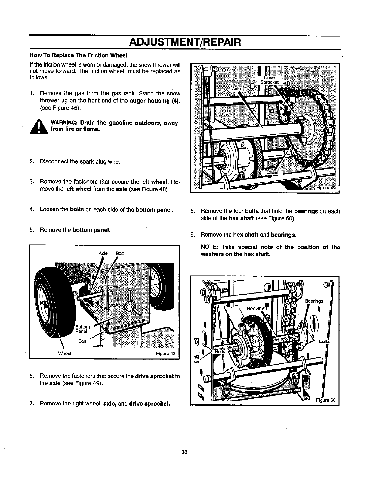
How To Replace The Friction Wheel
Ifthe frictionwheel is worn or damaged, Me snow thrower will
not move forward. The friction wheel must be replaced as
follows.
1. Remove the gas from the gas tank. Stand the snow
thrower up on the front end of the auger housing (4).
(see Figure 45).
_lb ARNING: Drain the gasoline outdoors, away
from fire or flame,
2. Disconnect the spark plug wire.
3. Remove the fasteners that secure the left wheel. Re-
move the left wheel from the axle (see Figure 48)
4. Loosen the bolts on each side of the bottom panel.
5. Remove the bottom panel.
6.
Axle Bolt
Wheel Figure 48
Remove the fasteners that securethe drive sprocket to
the axle (see Figure 49).
7. Remove the right wheel, axle, and drive sprocket.
8. Remove the four bolts that hold the bearings on each
side of the hex shaft (see Figure 50).
9. Remove the hex shaft and bearings.
NOTE: Take special note of the position of the
washers on the hex shaft.
5O
33
ADJUSTMENT/REPAIR
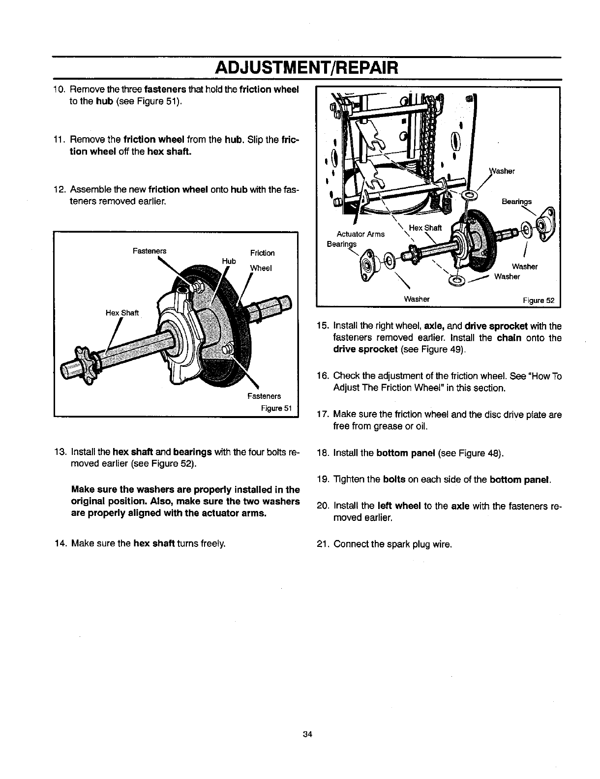
10. Remove the threefasteners that holdthe friction wheel
to the hub (see Figure 51).
11. Remove the friction wheel from the hub. Slip the fric-
tion wheel off the hex shaft.
12. Assemble the new friction wheel ontohub withthe fas-
teners removed earlier.
Fasteners Friction
Hub Wheel
Hex Shaft
Fasteners
Figure 51
Actuator Arms \\
Bearin_._
\
Washer
Washer
I_ Washer
Figure 52
15. Installthe right wheel, axle, and drive sprocket with the
fasteners removed earlier. Install the chain onto the
drive sprocket (see Figure 49).
16. Check the adjustmentof the frictionwheel. See "How To
Adjust The Friction Wheel" in this section.
17. Make sure the friction wheel and the disc drive plate are
free from grease or oil.
13. Installthe hex shaft and bearings withthe four bolts re-
moved earlier (see Figure 52).
Make sure the washers are properly installed in the
original position. Also, make sure the two washers
are properly aligned with the actuator arms.
18. Install the bottom panel (see Figure 48).
19. "i3ghtenthe bolts on each side of the bottom panel.
20. Install the left wheel to the axle with the fasteners re-
moved earlier.
14. Make sure the hex shaft turns freely. 21. Connect the spark plug wire.
34
ADJUSTMENT/REPAIR
AUGER SHEAR BOLT REPLACEMENT
The augers are securedto the auger shaft withspecial bolts
that are designed to break if an object becomes lodged in the
auger housing. Use of a harder bolt will reduce the protection
provided by the shear bolt. To replace a broken shear bolt,
proceed as follows:
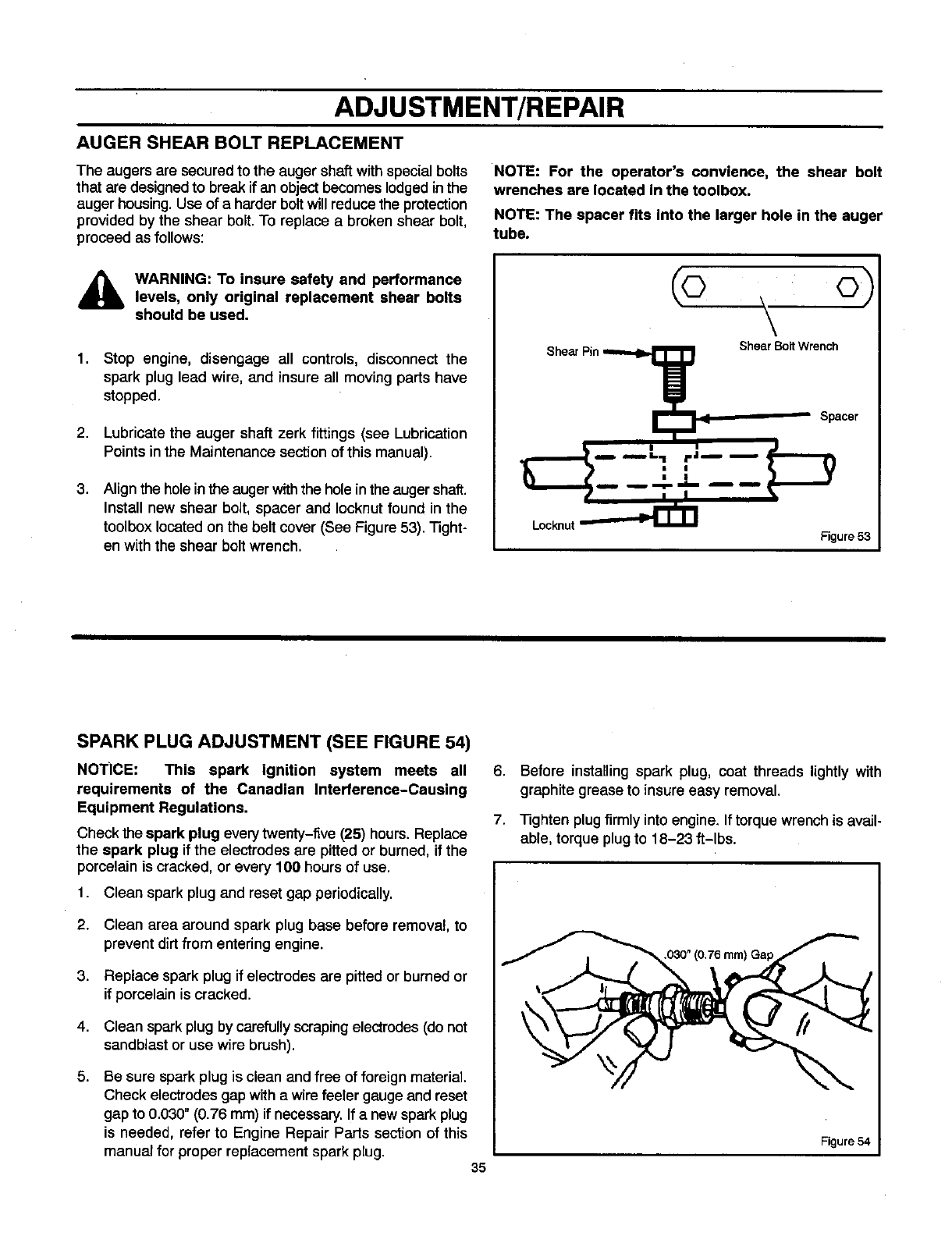
NOTE: For the operator's convlence, the shear bolt
wrenches are located in the toolbox.
NOTE: The spacer fits into the larger hole in the auger
tube.
_lj WARNING: To insure safety and performance
levels, only original replacement shear bolts
should be used.
1,
2,
3.
Stop engine, disengage all controls, disconnect the
spark plug lead wire, and insure all moving parts have
stopped.
Lubricate the auger shaft zerk fittings (see Lubrication
Points in the Maintenance section of this manual).
Align the hole in the auger with the holein the auger shaft.
Install new shear bolt, spacer and Iocknut found in the
toolbox located on the belt cover (See Figure 53). Tight-
en with the shear bolt wrench.
Locknut
(o , o)
\
Shear Bolt Wrench
Spacer
Figure 53
SPARK PLUG ADJUSTMENT (SEE FIGURE 54)
NOTICE: This spark ignition system meets all
requirements of the Canadian Interference-Causing
Equipment Regulations.
Check the spark plug every twenty-five (25) hours. Replace
the spark plug if the electrodes are pitted or burned, if the
porcelain is cracked, or every 100 hours of use.
1. Clean spark plug and reset gap periodically.
2. Clean area around spark plug base before removal, to
prevent dirt from entering engine.
3. Replace spark plug if electrodes are pitted or burned or
if porcelain is cracked.
4. Clean spark plug by carefully scraping electrodes (do not
sandblast or use wire brush).
6. Be sure spark plug is clean and free of foreign material.
Check electrodes gap with a wire feeler gauge and reset
gap to 0.030" (0.76 mm) if necessary. If a new spark plug
is needed, refer to Engine Repair Parts section of this
manual for proper replacement spark plug. 35
6. Before installing spark plug, coat threads lightly with
graphite grease to insure easy removal.
7. Tighten plug firmly into engine. If torque wrench is avail-
able, torque plug to 18-23 ft-lbs.
030" (0.76 rnrn)Gap
Figure 54
STORAGE
OFF SEASON STORAGE
_lb ARNING: Never store engine with fuel in tank
indoors or In enclosed, poorly ventilated enclo-
sures, where fuel fumes may reach an open
flame, spark or pilot light as on a furnace, water heater,
clothes dryer, etc.
Handle gasoline carefully. It is highly flammable and
careless use could result In serious fire damage to your
person and/or property.
Drain fuel into approved containers outdoors, away
from open flame.
If the snow blower is to be stored for thirty (30) days or more
at the end of the snow season, the following steps are
recommended to prepare your snow blower for storage.
NOTE: Gasoline must be removed or treated to prevent
gum deposits from forming in the tank, filter, hose, and
carburetor during storage.
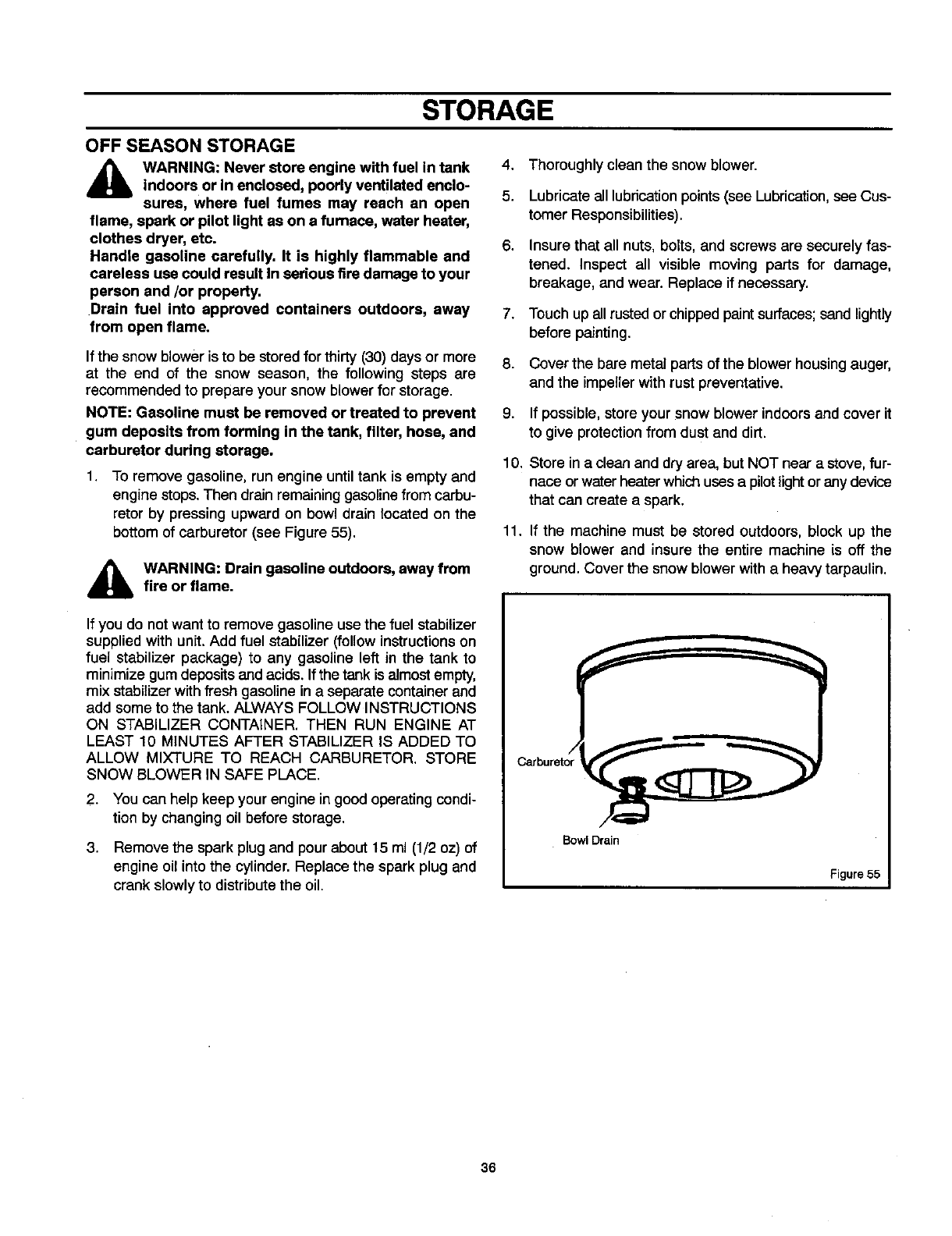
1. To remove gasoline, run engine until tank is empty and
engine stops. Then drain remaining gasoline from carbu-
retor by pressing upward on bowl drain located on the
bottom of carburetor (see Figure 55).
4_lb WARNING: Drain gasoline outdoors, away from
fire or flame.
4. Thoroughly clean the snow blower.
5. Lubricate all lubrication points (see Lubrication, see Cus-
tomer Responsibilities).
6. Insure that all nuts, bolts, and screws are securely fas-
tened. Inspect all visible moving pans for damage,
breakage, and wear. Replace if necessary.
7. Touch up all rusted or chipped paint surfaces; sand lightly
before painting.
8. Cover the bare metal parts of the blower housing auger,
and the impeller with rust preventative.
9. If possible, store your snow blower indoors and cover it
to give protection from dust and dirt.
10. Store in a clean and dry area, but NOT near a stove, fur-
nace or water heaterwhich usesa pilot light or any device
that can create a spark.
11. If the machine must be stored outdoors, block up the
snow blower and insure the entire machine is off the
ground. Cover the snow blower with a heavy tarpaulin.
If you do not want to remove gasoline use the fuel stabilizer
supplied with unit. Add fuel stabilizer (follow instructions on
fuel stabilizer package) to any gasoline left in the tank to
minimize gum deposits and acids. If the tank is almost empty,
mix stabilizerwith fresh gasoline in a separate container and
add some to the tank. ALWAYS FOLLOW INSTRUCTIONS
ON STABILIZER CONTAINER. THEN RUN ENGINE AT
LEAST 10 MINUTES AFTER STABILIZER IS ADDED TO
ALLOW MIXTURE TO REACH CARBURETOR. STORE
SNOW BLOWER IN SAFE PLACE.
2. You can help keep your engine in good operating condi-
tion by changing oil before storage,
3. Remove the spark plug and pour about 15 ml (1/2 oz) of
engine oil into the cylinder. Replace the spark plug and
crank slowly to distribute the oil.
Bowl Drain
Figure 55
36
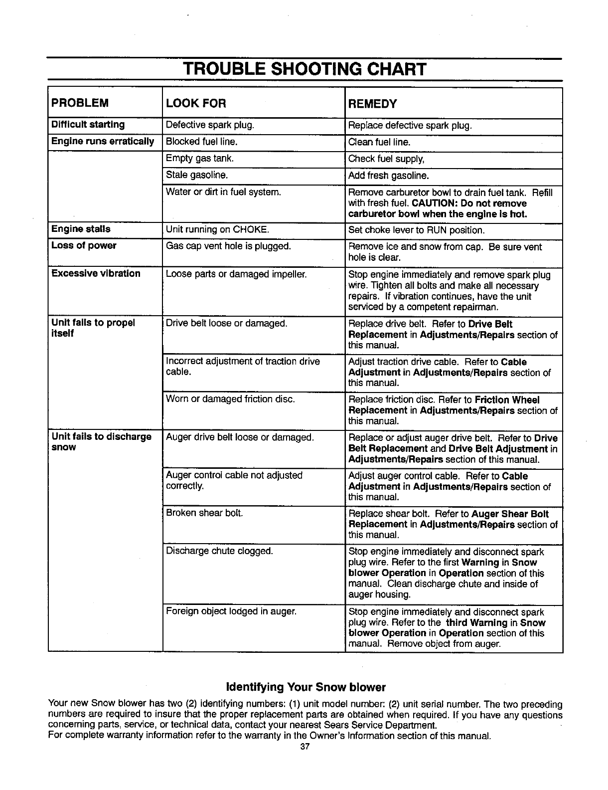
TROUBLE SHOOTING CHART
PROBLEM LOOK FOR REMEDY
Difficult starting Defective spark plug. Replace defectivespark plug.
Engine runs erratically Blocked fuel line. Clean fuel line.
Empty gas tank. Check fuel supply,
Stale gasoline. Add fresh gasoline.
Water or dirt in fuel system. Remove carburetorbowl to drainfuel tank. Refill
withfresh fuel. CAUTION: Do not remove
carburetor bowl when the engine Is hot.
Engine stalls Unit runningon CHOKE. Set choke lever to RUN position.
Loss of power Gas cap vent hole is plugged. Remove ice and snowfrom cap. Be surevent
hole is clear.
Excessive vibration Loose parts or damaged impeller. Stop engine immediatelyand remove sparkplug
wire. Tighten all bolts and make all necessary
repairs. If vibrationcontinues,have the unit
serviced by a competent repairman.
Unit tails to propel Drive belt loose or damaged. Replace drive belt. Refer to Drive Belt
itself Replacement in Adjuatments/Repairs sectionof
this manual.
Incorrect adjustment of traction drive Adjust traction drive cable. Refer to Cable
cable. Adjustment in Adjustments/Repairs section of
this manual.
Worn or damaged friction disc. Replace friction disc. Refer to Friction Wheel
Replacement in Adjustments/Repaira section of
this manual.
Unit fails to discharge Auger drive belt loose or damaged. Replace or adjust auger drive belt. Refer to Drive
snow Belt Replacement and Drive Belt Adjustment in
Adjustments/Repairs section of this manual.
Auger control cable notadjusted Adjustauger controlcable. Referto Cable
correctly. Adjustment in Adjustments/Repairs section of
this manual.
Brokenshear bolt. Replace shear bolt. Refer to Auger Shear Bolt
Replacement in Adjustments/Repairs sectionof
this manual.
Discharge chute clogged. Stop engine immediatelyand disconnectspark
plug wire. Refer to the first Warning in Snow
blower Operation in Operation sectionof this
manual. Clean discharge chute and insideof
auger housing.
Foreign object lodged in auger. Stop engine immediately and disconnect spark
plug wire, Refer to the third Warning in Snow
blower Operation in Operation sectionof this
manual. Remove object from auger.
Identifying Your Snow blower
Your new Snow blower has two (2) identifyingnumbers: (1) unit model number: (2) unit serial number. The two preceding
numbers are required to insure that the proper replacement parts are obtained when required. If you have any questions
concerning parts, service, or technical data, contact your nearest Sears Service Department.
For complete warranty information refer to the warranty in the Owner's Information section of this manual.
37
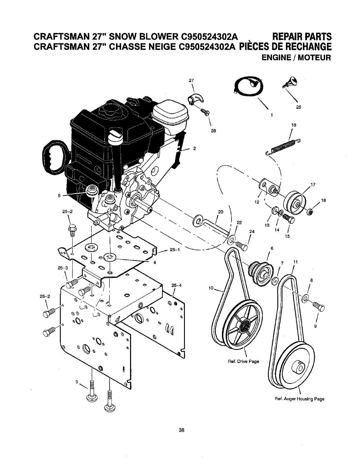
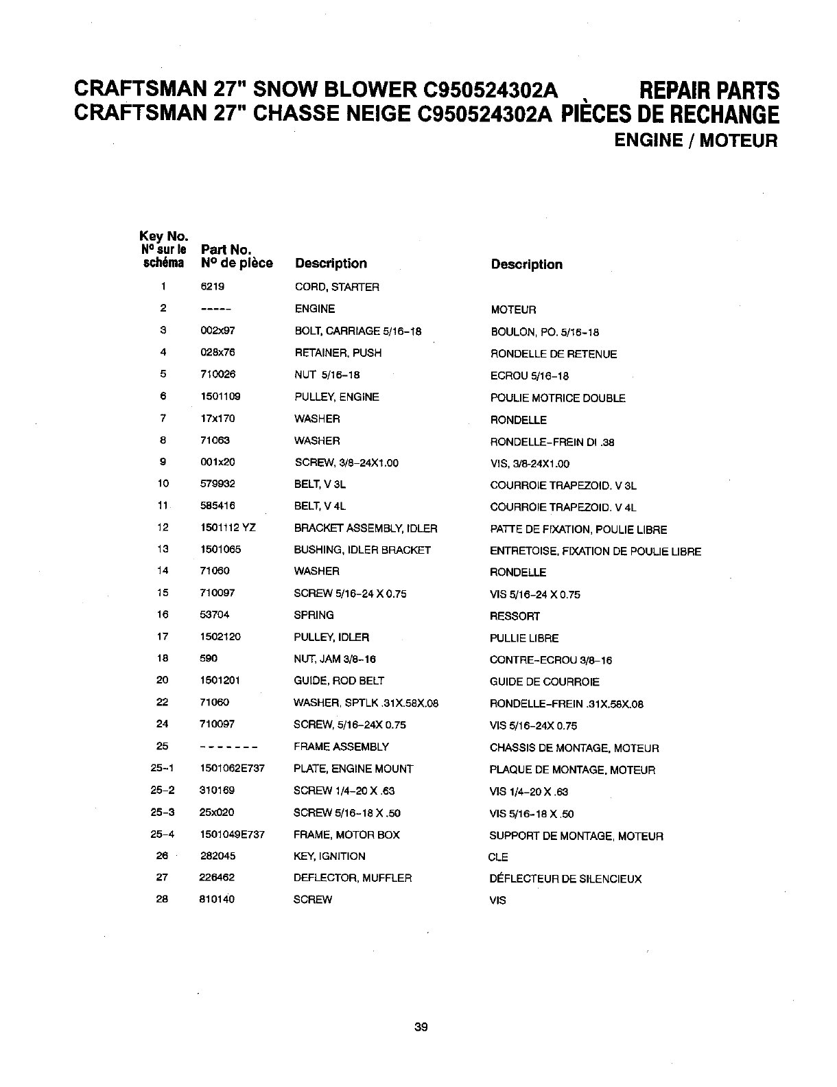
CRAFTSMAN 27" SNOW BLOWER C950524302A REPAIRPARTS
CRAFTSMAN 27" CHASSE NEIGE C950524302A PIECESDERECHANGE
ENGINE /MOTEUR
25-2
\
25-2
25-3
\
\
28
22
25-4 10._
15
\
24 14 /
/15
6
/11
17
18
8
/
/
9
Ref. Drive Page
3
Ref. Auger Housin9 Page
38
CRAFTSMAN 27" SNOW BLOWER C950524302A REPAIRPARTS
CRAFTSMAN 27" CHASSE NEIGE C950524302A PII=GESDERECHANGE
ENGINE /MOTEUR
Key No.
Nosur le Part No.
schema N° de pl_ce Description Description
1 6219 CORD, STARTER
2 ..... ENGINE MOTEUR
3002x97 BOLT, CARRIAGE 5/16-18 BOULON, PO. 5/16-18
4 028x76 RETAINER, PUSH RONDELLE DE RETENUE
5710026 NUT 5/16-18 ECROU 5/16-18
6 1501109 PULLEY, ENGINE POULIE MOTRICE DOUBLE
717x170 WASHER RONDELLE
871063 WASHER RONDELLE-FREIN DI .38
9 001x20 SCREW, 3/8-24Xl.00 VIS, 3/8-24X1.00
10 579932 BELT, V 3L COURROIE TRAPEZOID. V 3L
11 585416 BELT, V 4L COURROIE TRAPEZOID, V 4L
12 1501112 YZ BRACKET ASSEMBLY, IDLER PATrE DE FIXATION, POULIE LIBRE
13 1501065 BUSHING, IDLER BRACKET ENTRETOISE, FIXATION DE POULIE LIBRE
14 71O60 WASHER RONDELLE
15 710097 SCREW 5/16-24 X 0.75 VIS 5/16-24 X 0,75
16 53704 SPRING RESBORT
17 1502120 PULLEY, IDLER PULLIE LIBRE
18 590 NUT, JAM 3/8-16 CONTRE-ECROU 3/8-16
20 1501201 GUIDE, ROD BELT GUIDE DE COURROIE
22 71060 WASHER, SPTLK .31X.58X.08 RONDELLE-FREIN .31X.58X.08
24 710097 SCREW, 5/16-24X 0.75 VIB 5/16-24X 0.75
25 FRAME ASSEMBLY CHASSIS DE MONTAGE, MOTEUR
25-1 1501062E737 PLATE, ENGINE MOUNT PLAQUE DE MONTAGE, MOTEUR
25-2 310169 SCREW 1/4-20 X .63 VlS 1/4-20 X .63
25-3 25x020 SCREW 5/16-18 X .50 VIS 5/16-18 X .50
25-4 1501049E737 FRAME, MOTOR BOX SUPPORT DE MONTAGE, MOTEUR
26 282045 KEY, IGNITION CLE
27 226462 DEFLECTOR, MUFFLER DEFLECTEUR DE SILENClEUX
28 810140 SCREW VIB
39
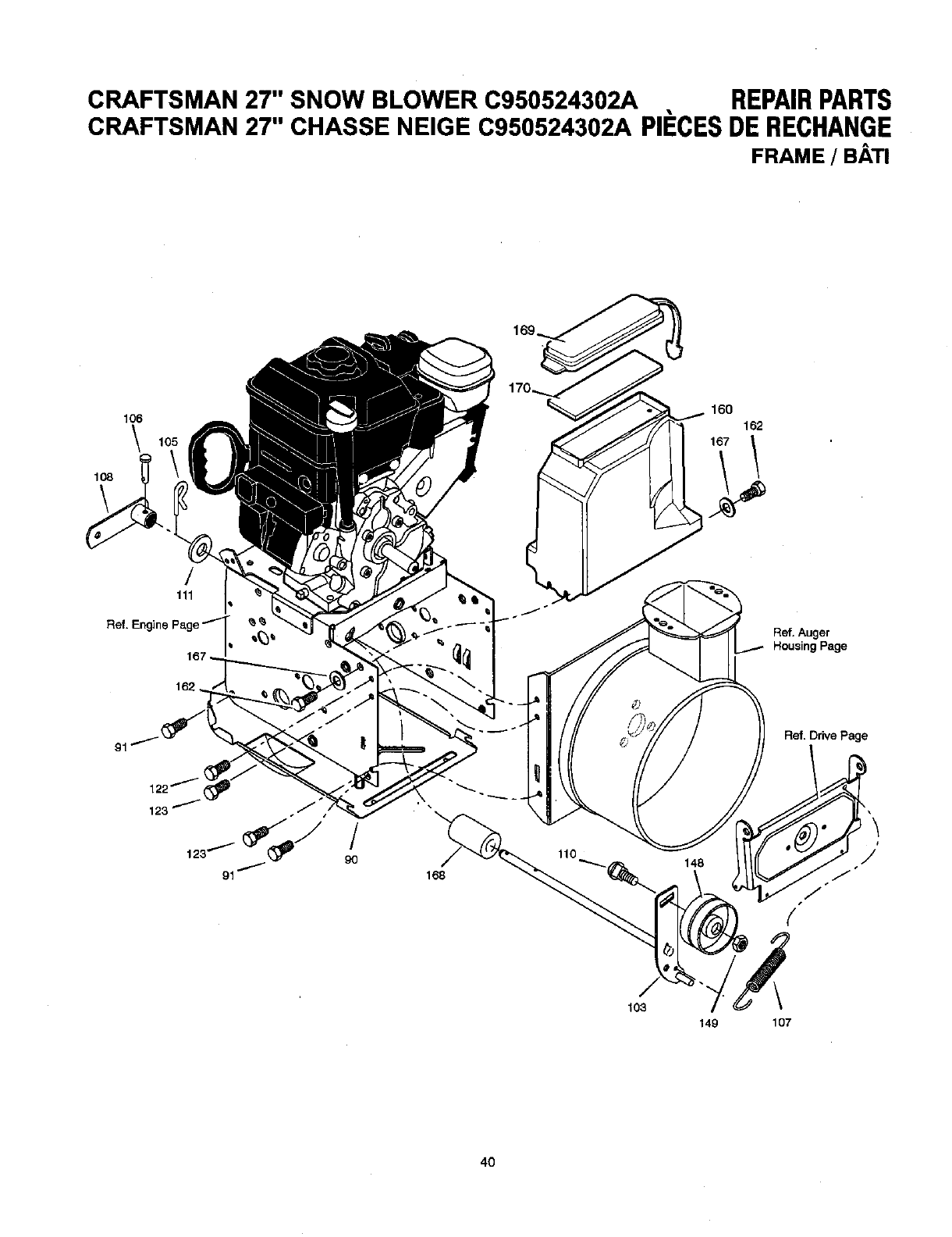
CRAFTSMAN 27" SNOW BLOWER C950524302A REPAIRPARTS
CRAFTSMAN 27" CHASSE NEIGE C950524302A PII=CESDE RECHANGE
FRAME /BATI
106
\
¢/
111
Ref. Engine Page _ _ _
I,
162.
91
122 _
123
91
/
90
168
160
162
167 1
Ref. Auger
Housing Page
Ref. Drive Page
103
149 107
4O
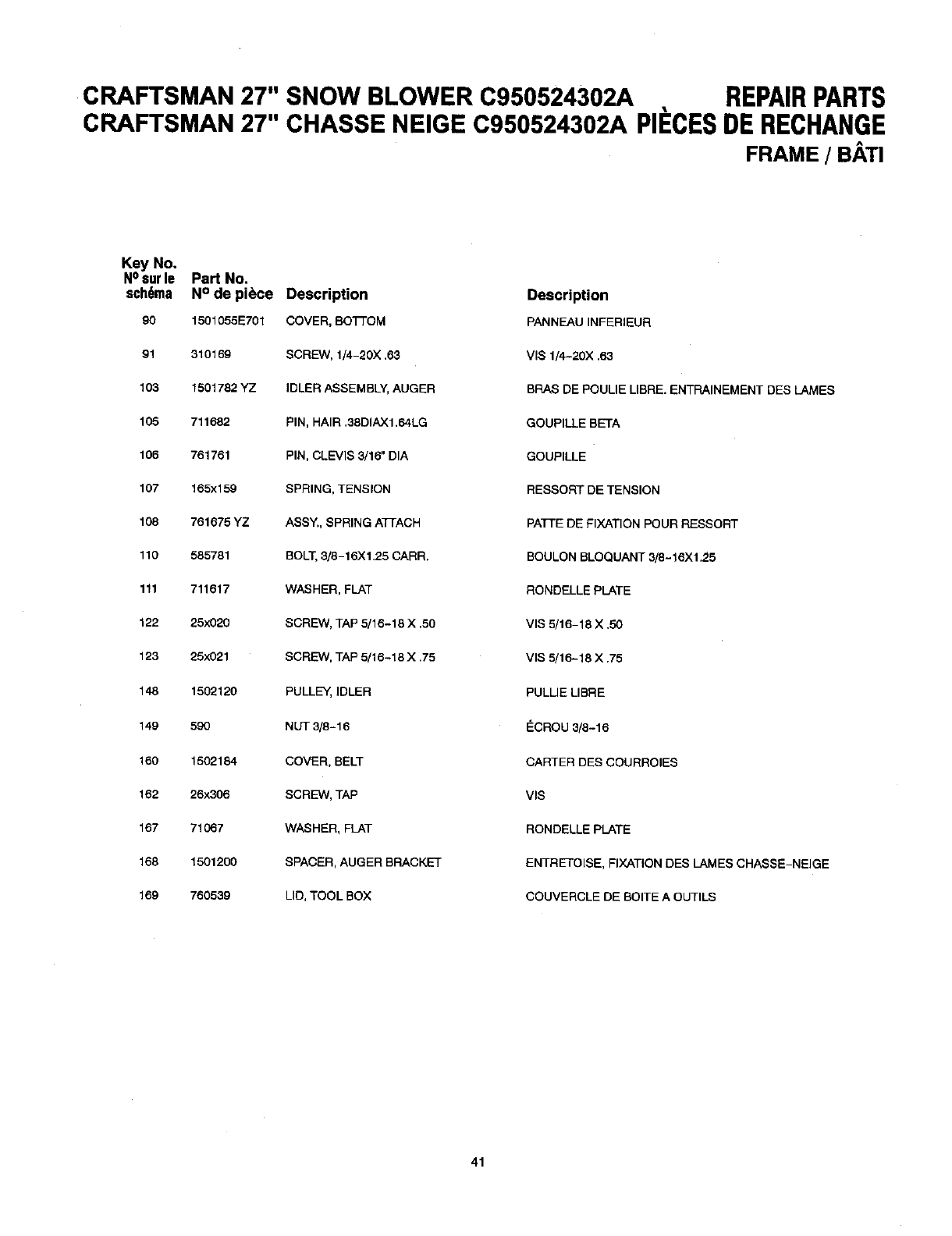
CRAFTSMAN 27" SNOW BLOWER C950524302A REPAIRPARTS
CRAFTSMAN 27" CHASSE NEIGE C950524302A PIECESDERECHANGE
FRAME /BATI
Key No.
NOsurle Part No.
sch6ma N° de piece Description
90 1501055E701 COVER, BOTTOM
91 310169 SCREW, 1/4-20X .63
103 1501782 YZ IDLER ASSEMBLY, AUGER
105 711682 PIN, HAIR ,38DIAX1.64LG
106 761751 PIN, CLEVIS 3/16" DIA
107 165x159 SPRING, TENSION
108 761675 YZ ASSY., SPRING ATrACH
110 585781 BOLT,3/8-16X 1.25 CARR,
111 711617 WASHER, FLAT
122 25x020 SCREW, TAP 5/16-18 X .50
123 25x021 SCREW. TAP 5/16-18 X .75
148 1502120 PULLEY, IDLER
149 590 NUT 3/8-16
160 1502184 COVER, BELT
162 26x306 SCREW, TAP
167 71067 WASHER, FLAT
158 1501200 SPACER, AUGER BRACKET
169 760539 LID, TOOL BOX
Description
PANNEAU INFERIEUR
VIS 1/4-20X .63
BRAS DE POULIE LIBRE. ENTRAINEMENT DES LAMES
GOUPILLE BETA
GOUPILLE
RESSORT DE TENSION
PATrE DE FIXATION POUR RESSORT
BOULON BLOQUANT 3/8-16Xl,25
RONDELLE PLATE
VIS 5/16-18 X ,50
VIS 5/16-18 X .75
PULLIE LIBRE
_CROU 3/8-16
CARTER DES COURROIES
VIS
RONDELLE PLATE
ENTRETOISE, FIXATION DES LAMES CHASSE-NEIGE
COUVERCLE DE BOITE A OUTILS
41
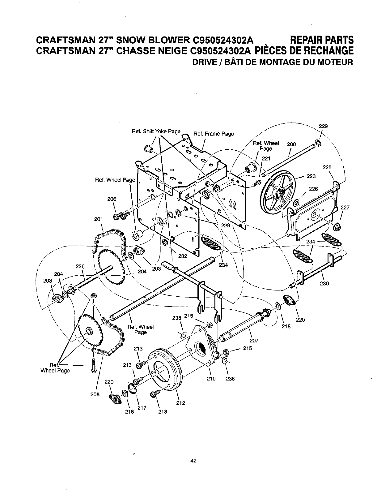
CRAFTSMAN 27" SNOW BLOWER C950524302A REPAIRPARTS
CRAFTSMAN 27" CHASSE NEIGE C950524302A PI#CESDERECHANGE
DRIVE /BATI DE MONTAGE DU MOTEUR
/
f-
/ 236
204
\
Ref. Shift Yoke Page
Ref. Wheel '_
206
\
201
\
/
!
\
Ref. Wheel
Page
213
Ref. Frame Page /
¢/_ef. Wheel 200
Page
238 215.
\
226
\ \
\
/ \
' \
/
230
\
220
218
207
215
Wheel Page
208
213\
220
218
212
217 213
\
210 238
42
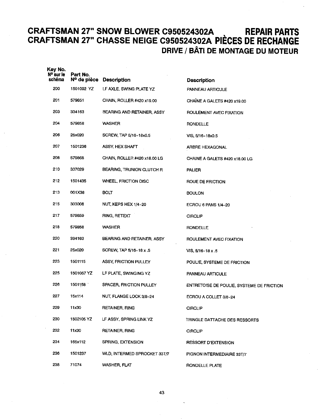
CRAFTSMAN 27" SNOW BLOWER 0950524302A REPAIRPARTS
CRAFTSMAN 27" CHASSE NEIGE C950524302A PIECESDERECHANGE
DRIVE /BATI DE MONTAGE DU MOTEUR
Key No.
N°8urle Part No.
stigma N° de piece Description Description
200 15O1092 YZ LF AXLE, SWING PLATE YZ PANNEAU ARTICULE
201 579851 CHAIN, ROLLER #42O xl 9,00 CHAINE A GALETS #420 x19,00
203 334163 REARING AND RETAINER, ASSY ROULEMENT AVEC FIXATION
204 579858 WASHER RONDELLE
206 25x020 SCREW, TAP 5/16-18x0.5 VIS, 5/16-18x0.5
207 1501236 ASSy, HEX SHAFT ARBRE HEXAGONAL
208 579868 CHAIN, ROLLER #420 xl 8.00 LG CHAINE A GALETS #420 xl 8.00 LG
210 337029 BEARING, TRUNION CLUTCH R PALIER
212 1501435 WHEEL, FRICTION DISC ROUE DE FRICTION
213 001X38 BOLT BOULON
215 303008 NUT, KEPS HEX 1/4-20 ECROU 6 PANS 1/4-20
217 579859 RING, RETIEXT CIRCMP
218 579858 WASHER RONDELLE
220 334163 BEARING AND RETAINER, ASSY ROULEMENT AVEC FIXATION
221 25x020 SCREW, TAP 5/16-18 x .5 VIS, 5/16-18 x .5
223 1501115 ASSY, FRICTION PULLEY POULIE, SYSTEME DE FRICTION
225 1501057 YZ LF PLATE, SWINGING YZ PAN NEAU ARTICULE
226 15011.58 SPACER, FRICTION PULLEY ENTRETOISE DE POULIE, SYSTEME DE FRICTION
227 15x114 NUT, FLANGE LOCK 3/8-24 ECROU A COLLET 3/8-24
229 11x30 RETAINER, RING ClRCLIP
230 1502105 YZ LF ASSY, SPRING LINK YZ TRINGLE DATTACHE DES RESSORTS
232 11x30 RETAINER, RING CIRCUP
234 165x112 SPRING, EXTENSION RESSORT D'EXTENSION
236 1501237 WLD, INTERMED SPROCKET 33T/7 PIGNON INTERMEDIAIRE 33T/7
238 71074 WASHER, FLAT RONDELLE PLATE
43
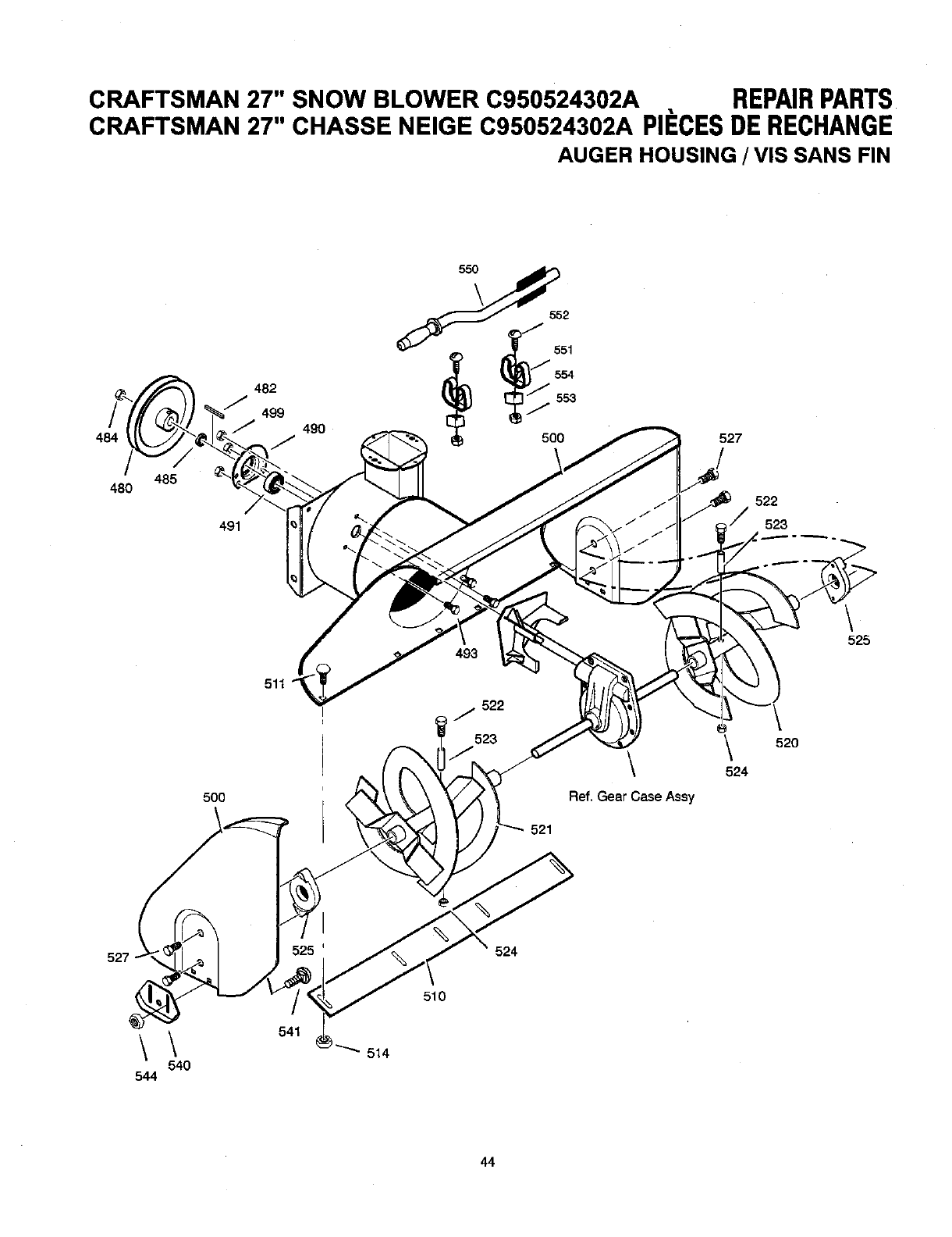
CRAFTSMAN 27" SNOW BLOWER C950524302A REPAIRPARTS
CRAFTSMAN 27" CHASSE NEIGE C950524302A PII=CESDE RECHANGE
AUGER HOUSING /VIS SANS FIN
484
485
48O
49O 5oo 527
j_ 522
491 523
493 525
500
522
J
523
j \ \ 520
524
Ref. Gear Case Assy
521
527 525 524
\
544
\
540
541
510
514
44
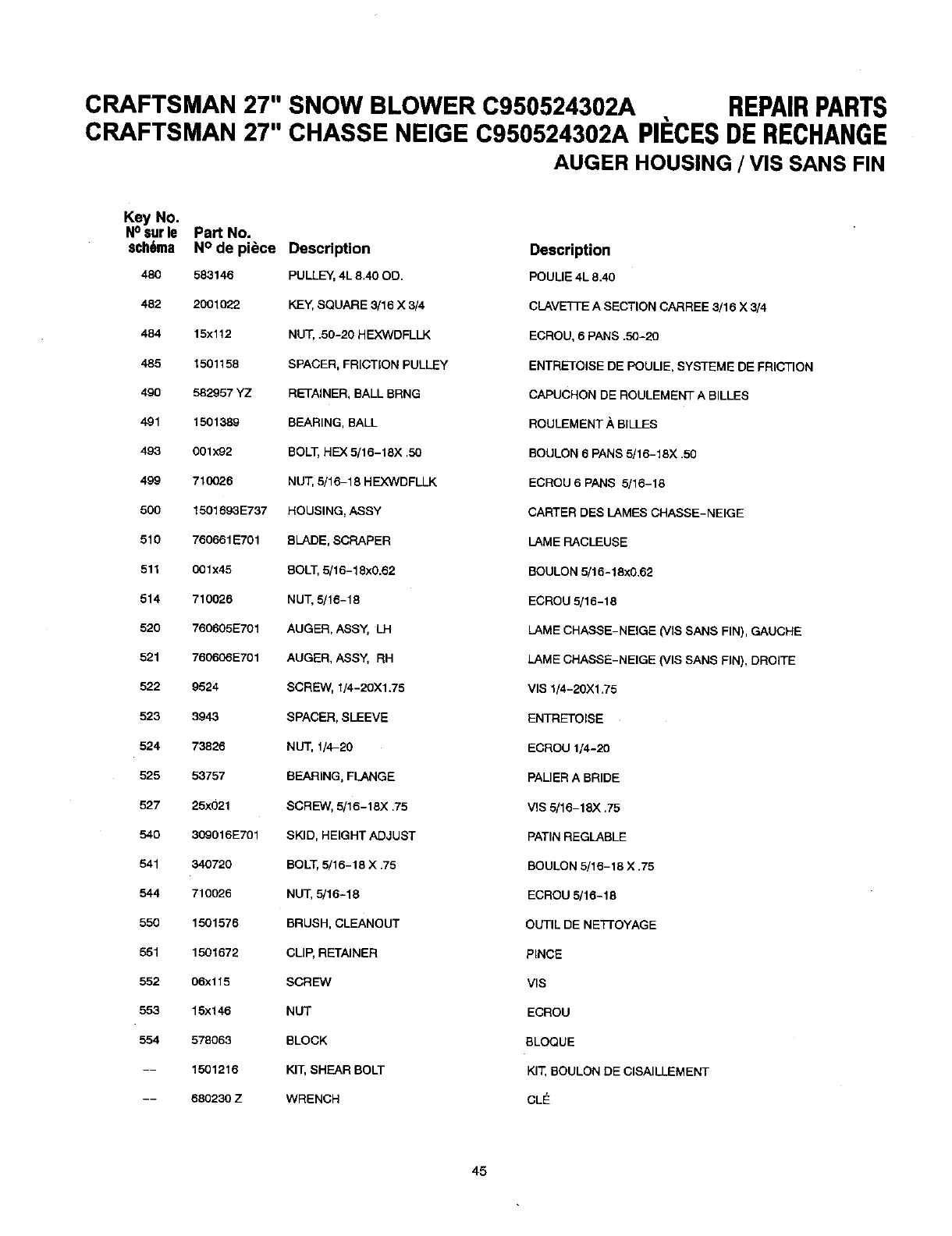
CRAFTSMAN 27" SNOW BLOWER C950524302A REPAIRPARTS
CRAFTSMAN 27" CHASSE NEIGE C950524302A PII=CESDE RECHANGE
AUGER HOUSING /VIS SANS FIN
Key No.
N° surle Part No.
sch6ma N° de piece Description Description
480 583146 PULLEY, 4L 8,40 OD. POUUE 4L 8.40
482 2001022 KEY, SQUARE 3/16 X3/4 CLAVETi-E A SECTION CARREE 3/16 X3/4
484 15x112 NUT, .50-20 H EX3NDFLLK ECROU, 6 PANS .50-20
485 1501158 SPACER, FRICTION PULLEY ENTRETOISE DE POULIE, SYSTEME DE FRICTION
490 582957 YZ RETAINER, BALL BRNG CAPUCHON DE ROULEMENT A BILLES
491 1501889 BEARING, BALL ROULEMENT/_ BILLES
493 001x92 BOLT, HEX 5/16-18X .50 BOULON 6 PANS 5/16-18X .50
499 710026 NUT, 5/16-18 HEX3NDPLLK ECROU 6 PANS 5/18-18
500 1501693E737 HOUSING, ASSY CARTER DES LAMES CHASSE-NEIGE
510 760661E701 BLADE, SCRAPER LAME RACLEUSE
511 001x45 BOLT, 5/16-18x0.62 BOULON 5/16-18x0.62
514 710028 NUT, 5/16-18 ECROU 5/16-18
520 760605E701 AUGER, ASSY, LH LAME CHASSE-NEIGE (VIS SANS FIN), GAUCHE
521 7606e6E701 AUGER, ASSY, RH LAME CHASSE-NEIGE (VIS SANS FIN), DROITE
522 9524 SCREW, 1/4-20)(1.75 VIS 1/4-20)(1.75
523 3943 SPACER, SLEEVE ENTRETOISE
524 73826 NUT, 1/4-20 ECROU 1/4-20
525 53757 BEARING, FLANGE PALIER A BRIDE
527 25x021 SCREW, 5/16-18)( .75 VIS 5/16-18)( .75
540 309016E701 SKID, HEIGHT ADJUST PATIN REGLABLE
541 340720 BOLT, 5/16-18 X .75 BOULON 5/16-18 X .75
544 710026 NUT, 5/16-18 ECROU 5/15-18
550 1501576 BRUSH, CLEANOUT OUTIL DE NE'F]'OYAGE
551 1501672 CLIP, RETAINER PINCE
552 06x115 SCREW VlS
553 15x146 NUT ECROU
554 578063 BLOCK BLOQUE
-- 1501216 KIT, SHEAR BOLT KIT, BOULON DE CISAILLEMENT
-- 880230 Z WRENCH CLE
45
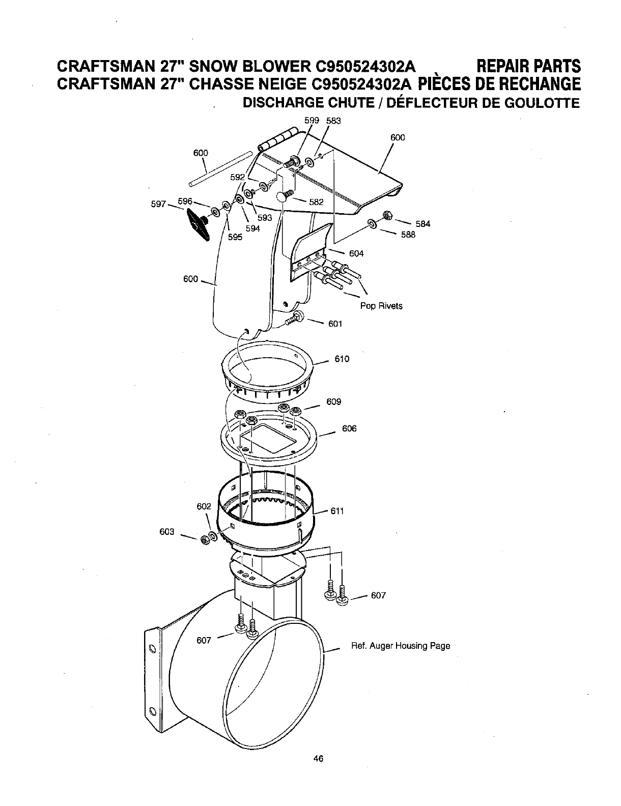
CRAFTSMAN 27" SNOW BLOWER C950524302A REPAIRPARTS
CRAFTSMAN 27" CHASSE NEIGE C950524302A PIECESDERECHANGE
DISCHARGE CHUTE /D(:::FLECTEUR DE GOULOTTE
599 583
600
600
584
594 _ 588
6O4
Pop Rivets
601
610
609
606
602
\
603
607 Ref. Auger Housing Page
46
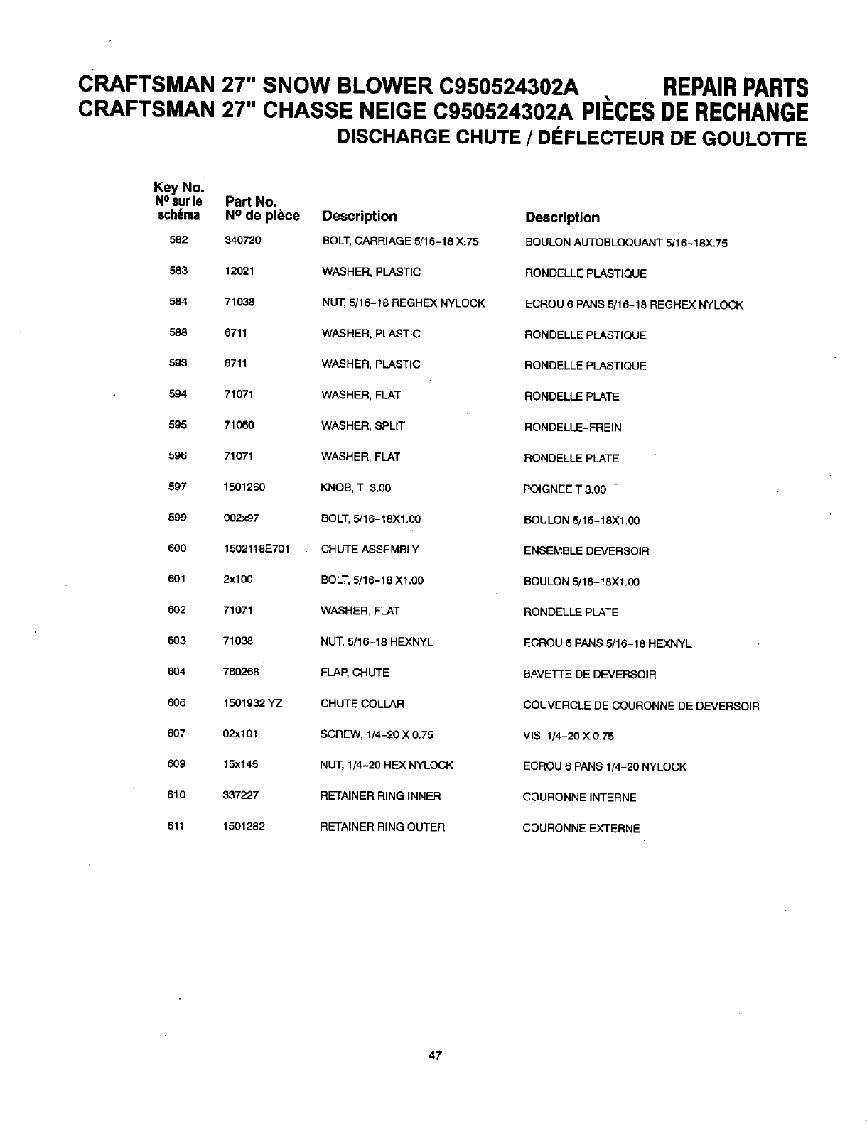
CRAFTSMAN 27" SNOW BLOWER C950524302A REPAIRPARTS
CRAFTSMAN 27" CHASSE NEIGE C950524302A PIECESDERECHANGE
DISCHARGE CHUTE /DI=FLECTEUR DE GOULOTrE
Key No.
NOsur16 Part No.
6ch6ma N° de piece Description
582 340720 BOLT, CARRIAGE 5/15-16 X;75
583 12021 WASHER, PLASTIC
584 71038 NUT, 5/18-18 REGHEX NYLOCK
588 6711 WASHER, PLASTIC
593 5711 WASHER, PLASTIC
594 71071 WASHER, FLAT
595 71060 WASHER, 8PUT
596 71071 WASHER, FLAT
597 1501260 KNOB, T 3.00
599 002x97 BOLT, 5/16-18X1.00
600 1502118E701 CHUTE ASSEMBLY
601 2xlco BOLT,5/16-15 XI.00
602 71071 WASHER, FLAT
603 71038 NUT, 5/16-18 HEXNYL
604 760288 FLAP, CHUTE
606 1501932 YZ CHUTE COLLAR
607 02x101 SCREW, 1/4-20 X 0.75
609 15x145 NUT, 1/4-20 HEX NYLOCK
610 337227 RETAINER RING INNER
611 1501282 RETAINER RING OUTER
Description
BOULON AUTOBLOQUANT 5/16-18X.75
RONDELLE PLASTIQUE
ECROU 8 PANS 5/15-18 REGREX NYLOCK
RONDELLE PLASTIQUE
RONDELLE PLASTIQUE
RONDELLE PLATE
RONDELLE-FREIN
RONDELLE PLATE
POIGNEE T 3.00 '
BOULON 5/15-18X1,00
ENSEMBLE DEVERSOIR
BOULON 5/18-18X1.CO
RONDELLE PLATE
ECROU 5 PANS 5/18-18 HEXNYL
BAVETTE DE DEVERSOIR
COUVERCLE DE COURONNE DE DEVERSOIR
VIS 1/4-20 X 0.75
ECROU 6 PANS 1/4-20 NYLOCK
COURONNE INTERNE
COURONNE EXTERNE
47
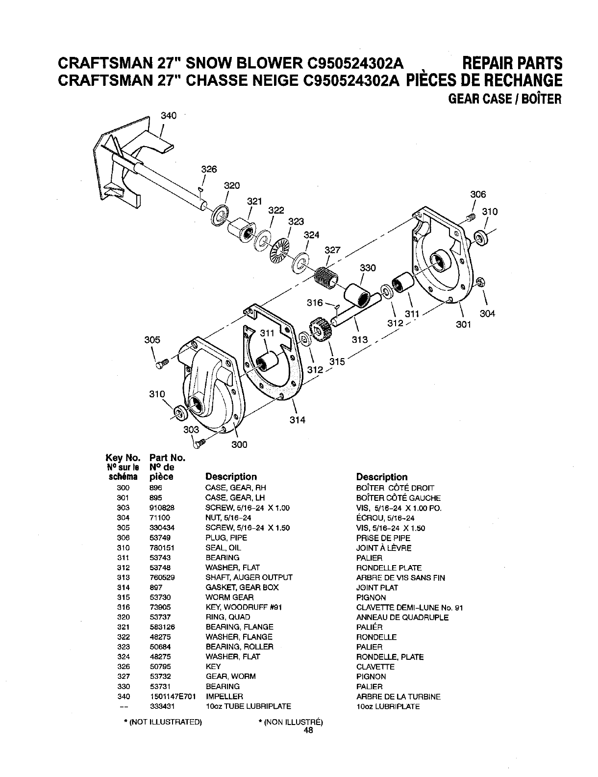
CRAFTSMAN 27" SNOW BLOWER C950524302A REPAIRPARTS
CRAFTSMAN 27" CHASSE NEIGE C950524302A PIECESDERECHANGE
GEARCASE/B0iTER
340
326
/320 306
321 J
322 /310
323
324 /
327
330
\
304
301
310
303 314
300
Key No. Part No.
NOsurle N° de
sch6ma piece Description Description
300 896 CASE, GEAR, RH BOTTER OC)TE DROIT
301 895 CASE, GEAR, LH BOiTER C_)TE GAUCHE
303 910828 SCREW, 5/16-24 X 1.00 VIS, 5/16-24 X 1.00 PO.
304 71100 NUT, 5/16-24 ECROU, 5/16-24
505 330434 SCREW, 5/16-24 X 1.50 VIS, 5/16-24 X 1.50
306 53749 PLUG, PIPE PRISE DE PIPE
310 780151 SEAL, OIL JOINT .'_LE'VRE
311 53743 BEARING PALIER
312 53748 WASHER, FLAT RONDELLE PLATE
313 750529 SHAFT, AUGER OUTPUT ARBRE DE VIS SANS FIN
314 897 GASKET, GEAR BOX JOINT PLAT
315 53730 WORM GEAR PIGNON
316 73905 KE_, WOODRUFF #91 CLAVETTE DEMI-LUNE No. 91
320 53737 RING, QUAD ANNEAU DE QUADRUPLE
321 583126 BEARING, FLANGE PALIER
322 48275 WASHER, FLANGE RONDELLE
323 50684 BEARING, ROLLER PALIER
324 48275 WASHER, FLAT RONDELLE, PLATE
326 50795 KEY CLAVE1-FE
327 53732 GEAR, WORM PIGNON
330 53731 BEARING PAL]ER
340 1501147E701 IMPELLER ARBRE DE LA TURBINE
-- 333431 10oz TUBE LUBRIPLATE 10oz LUBRIPLATE
* (NOT ILLUSTRATED) *(NON ILLUSTRFt)
48
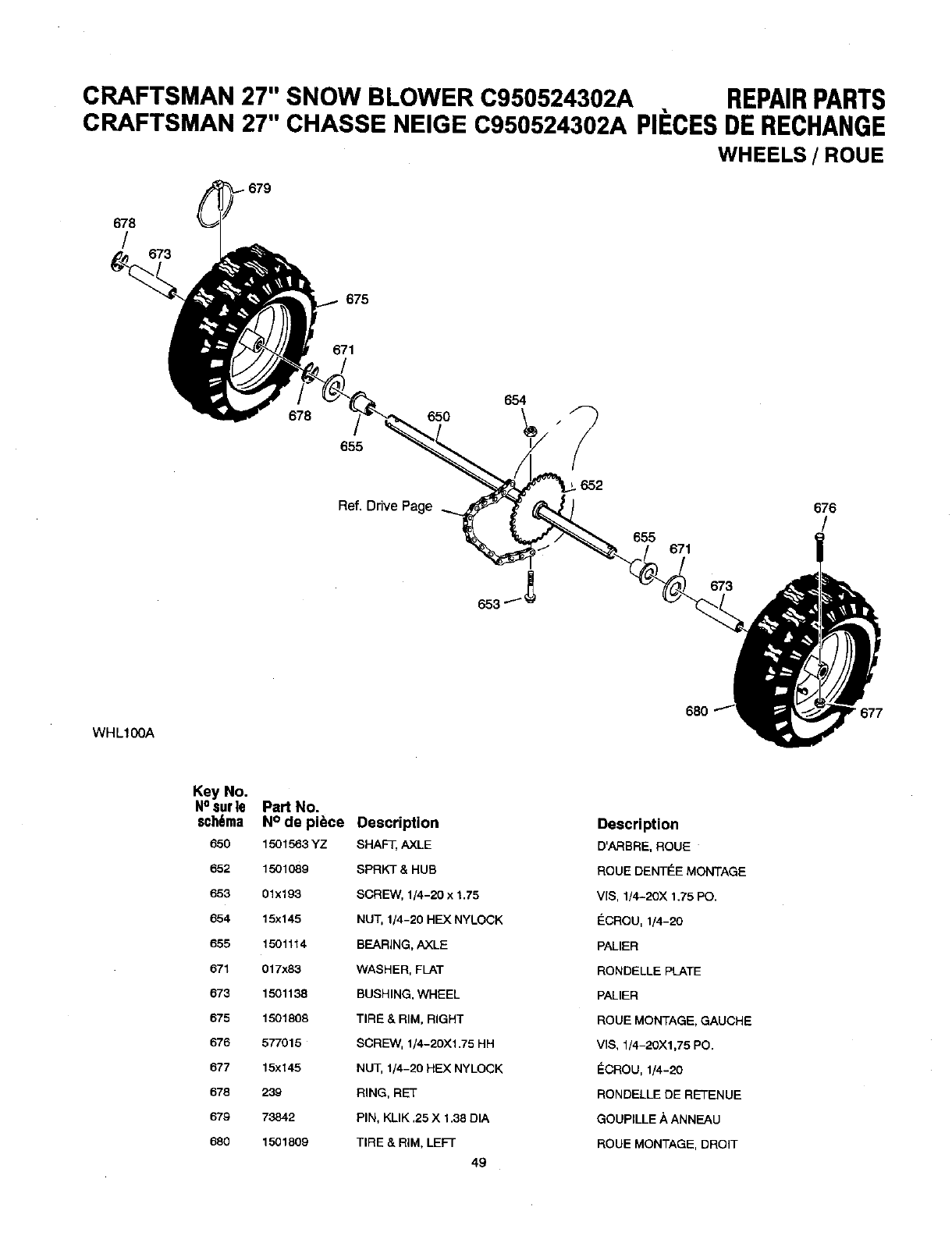
CRAFTSMAN 27" SNOW BLOWER C950524302A REPAIRPARTS
CRAFTSMAN 27" CHASSE NEIGE C950524302A PIECESDE RECHANGE
WHEELS /ROUE
678
/679
675
671
678 650
655
Ref. Drive Page
654
652
655 671
673
676
/
WHL100A
Key No,
NOsurle
sch6ma
650
652
653
654
655
671
873
875
070
677
678
679
680
Pad No.
N° de piece
1501563YZ
1501089
01x193
15x145
1501114
017x83
1501138
1501808
577015
15x145
239
73842
1501809
Description
SHAFT, AXLE
SPRKT & HUB
SCRE3/V,1/4-20 x 1,75
NUT, 1/4-20 HEX NYLOCK
BEARING, AXLE
WASHER, FLAT
BUSHING, WHEEL
TIRE & RIM, RIGHT
SCREW, 1/4-20)(1.75 HH
NUT, 1/4-20 HEX NYLOCK
RING, RET
PIN, KLIK ,25 X 1.38 DIA
TIRE & RIM, LEFT
49
Description
D'ARBRE, ROUE
ROUE DENTINE MONTAGE
V[S, 1/4-20X 1.75 PO.
I_CROU, 1/4-20
PALIER
RONDELLE PLATE
PALIER
ROUE MONTAGE, GAUCHE
VIS, 1/4-20)(1,75 PO.
ECROU, 1/4-20
RONDELLE DE RETENUE
GOUPILLE A ANNEAU
ROUE MONTAGE, DROIT
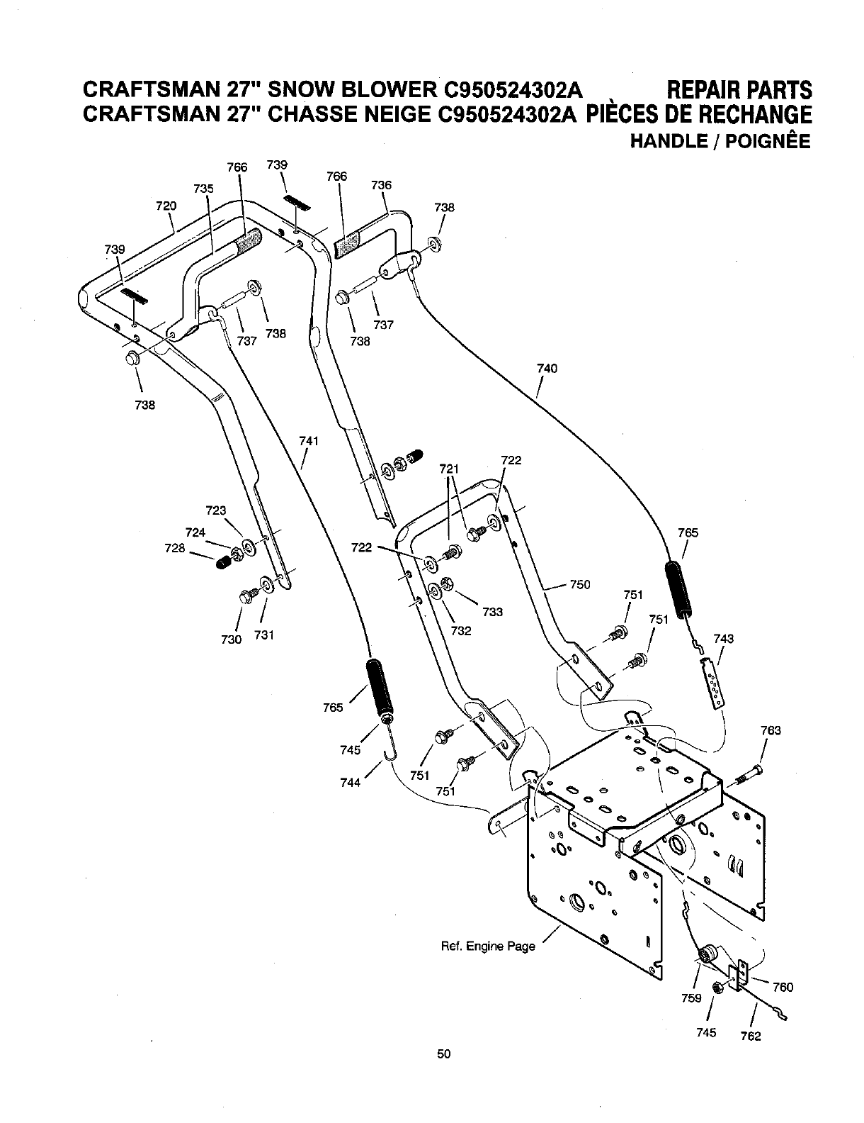
CRAFTSMAN 27" SNOW BLOWER C950524302A REPAIRPARTS
CRAFTSMAN 27" CHASSE NEIGE C950524302A PII=GESDERECHANGE
HANDLE /POIGNEE
766 739 766
735 \736
720 738
/
739
\
738
737
738 738
740
741
/721 722
723
724 _765
728 722 /
751
t732733 /
730 731 z_
751
743
765
763
751 _
Ref. Engine Page
_'_760
759
745 762
5O
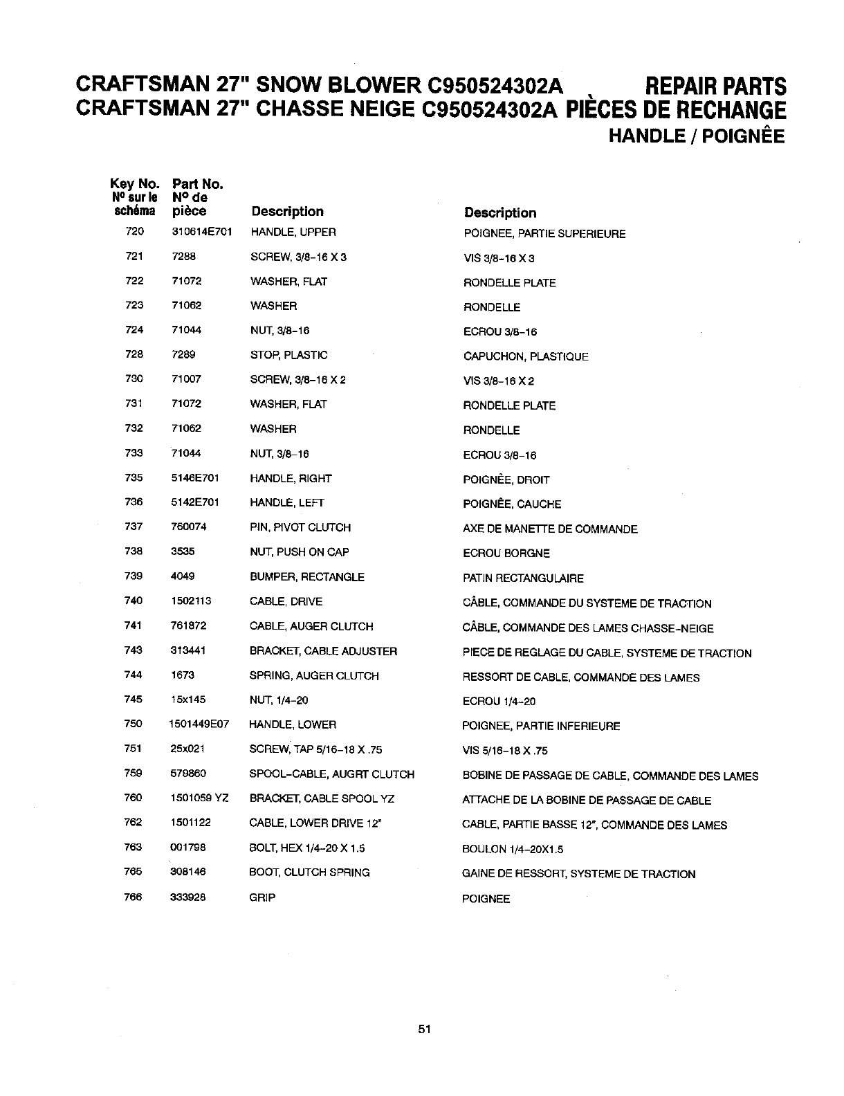
CRAFTSMAN 27" SNOW BLOWER C950524302A REPAIRPARTS
CRAFTSMAN 27" CHASSE NEIGE C950524302A PIECES DE RECHANGE
HANDLE /POIGNI=E
Key No. Part No.
N° 6ur le N ° de
sch6ma piece Description
720 310614E701 HANDLE, UPPER
721 7288 SCREW, 3/8-16 X 3
722 71072 WASHER, FLAT
723 71062 WASHER
724 71044 NUT, 3/8-16
728 7289 STOP, PLASTIC
730 71007 SCREW, 3/8-16 X 2
731 71072 WASHER, FLAT
732 71062 WASHER
733 71044 NUT, 3/8-16
735 5146E701 HANDLE, RIGHT
736 5142E701 HANDLE, LEFT
737 760074 PiN, PIVOT CLUTCH
738 3535 NUT, PUSH ON CAP
739 4049 BUMPER, RECTANGLE
740 1502113 CABLE, DRIVE
741 761872 CABLE, AUGER CLUTCH
743 313441 BRACKET, CABLE ADJUSTER
744 1673 SPRING, AUGER CLUTCH
745 15x145 NUT, 1/4-20
750 1501449E07 HANDLE, LOWER
751 25x021 SCREW, TAP 5/16-18 X ,75
759 579860 SPOOL-CABLE, AUGRT CLUTCH
760 1501059 YZ BRACKET, CABLE SPOOL YZ
762 1501122 CABLE, LOWER DRIVE 12"
763 001798 BOLT, HEX 1/4-20 X 1.5
765 308146 BOOT, CLUTCH SPRING
766 333928 GRIP
Description
POIGNEE, PARTIE SUPERIEURE
VIS 3/8-16 X 3
RONDELLE PLATE
RONDELLE
ECROU 3/8-16
CAPUCHCN, PLASTIQUE
VIS 3/8-16 X2
RONDELLE PLATE
RONDELLE
ECROU 3/8-16
POIGNEE, DROIT
POIGNEE, CAUCHE
AXE DE MANE_E DE COMMANDE
ECROU BORGNE
PATIN RECTANGULAIRE
CABLE, COMMANDE DU SYSTEME DE TRACTION
CABLE, COMMANDE DES LAMES CHASSE-NEIGE
PrECE DE REGLAGE DU CABLE, SYSTEME DE TRACTION
RESSORT DE CABLE, COMMANDE DES LAMES
ECROU 1/4-20
POIGNEE, PARTIE INFERIEURE
VlS 5/16-18 X ,75
BOBINE DE PASSAGE DE CABLE, COMMANDE DES LAMES
ATFACHE DE LA BOBINE DE PASSAGE DE CABLE
CABLE, PARTIE BASSE 12", COMMANDE DES LAMES
BOULON 1/4-20Xl.5
GAINE DE RESSORT, SYSTEME DE TRACTION
POIGNEE
51
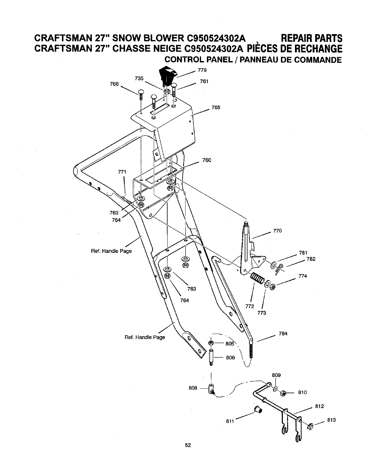
CRAFTSMAN 27" SNOW BLOWER C950524302A REPAIRPARTS
CRAFTSMAN 27" CHASSE NEIGE C950524302A PII=CESDE RECHANGE
CONTROL PANEL /PANNEAU DE COMMANDE
766 735 761
765
771
760
763
764
770
Ref. Handle Page
_781782
763
764 772
773
774
Ref. Handle Page 784
52
813
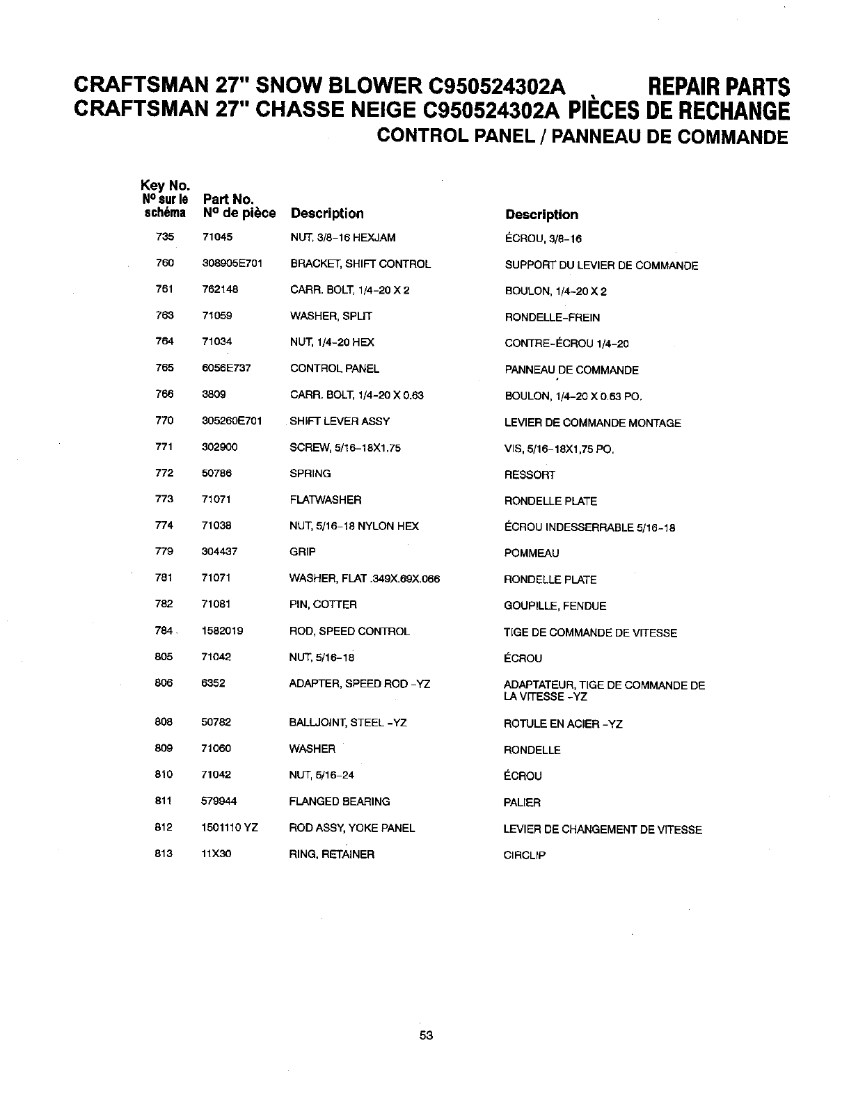
CRAFTSMAN 27" SNOW BLOWER C950524302A REPAIRPARTS
CRAFTSMAN 27" CHASSE NEIGE C950524302A PIF:CESDERECHANGE
CONTROL PANEL /PANNEAU DE COMMANDE
Key No.
N°6urle Part No.
sch6ma N° de piece Description Description
735 71045 NUT, 3/8-16 HEXJAM _:CROU, 3/8-16
760 308905E701 BRACKET, SHIFT CONTROL SUPPORT DU LEVIER DE COMMANDE
761 762148 CARR. BOLT,1/4-20 X 2 BOULON, 1/4-20 X 2
763 71059 WASHER, SPLIT RONDELLE-FREIN
764 71034 NUT, 1/4-20 HEX CONTRE-E_CROU 1/4-20
765 6056E737 CONTROL PANEL PANNEAU DE COMMANDE
766 3809 CARR. BOLT, 1/4-20 X0.63 BOULON, 1/4-20 X 0.63 PC.
770 305260E701 SHIFT LEVER ASSY LEVlER DE COMMANDE MONTAGE
771 302900 SCREW, 5/16-18X1.75 VIS, 5/16-18X1,75 PC,
772 50786 SPRING RESSORT
773 71071 FLATWASR ER RONDELLE PLATE
774 71038 NUT, 5/16-18 NYLON REX ECROU INDESSERRABLE 5/16-18
779 304437 GRIP POMMEAU
781 71071 WASHER, FLAT .349X.69X.066 RONDELLE PLATE
782 71081 PIN, COTTER GOUPILLE, FENDUE
784. 1582019 ROD, SPEED CONTROL TIGE DE COMMANDE DE VITESSE
805 71042 NUT, 5/16-18 _:CROU
806 6352 ADAPTER, SPEED ROD -YZ ADAPTATEU R, TIGE DE COMMANDE DE
LA VITESSE -YZ
808 50782 BALL.JOINT, STEEL -YZ ROTULE EN ACIER -YZ
809 71060 WASHER RONDELLE
810 71042 NUT, 5/16-24 ECROU
811 579944 FLANGED BEARING PALIER
812 1501110 YZ ROD ASSY, YOKE PANEL LEVlER DE CHANGEMENT DE VITESSE
813 11X30 RING, RETAINER CIRCLIP
53
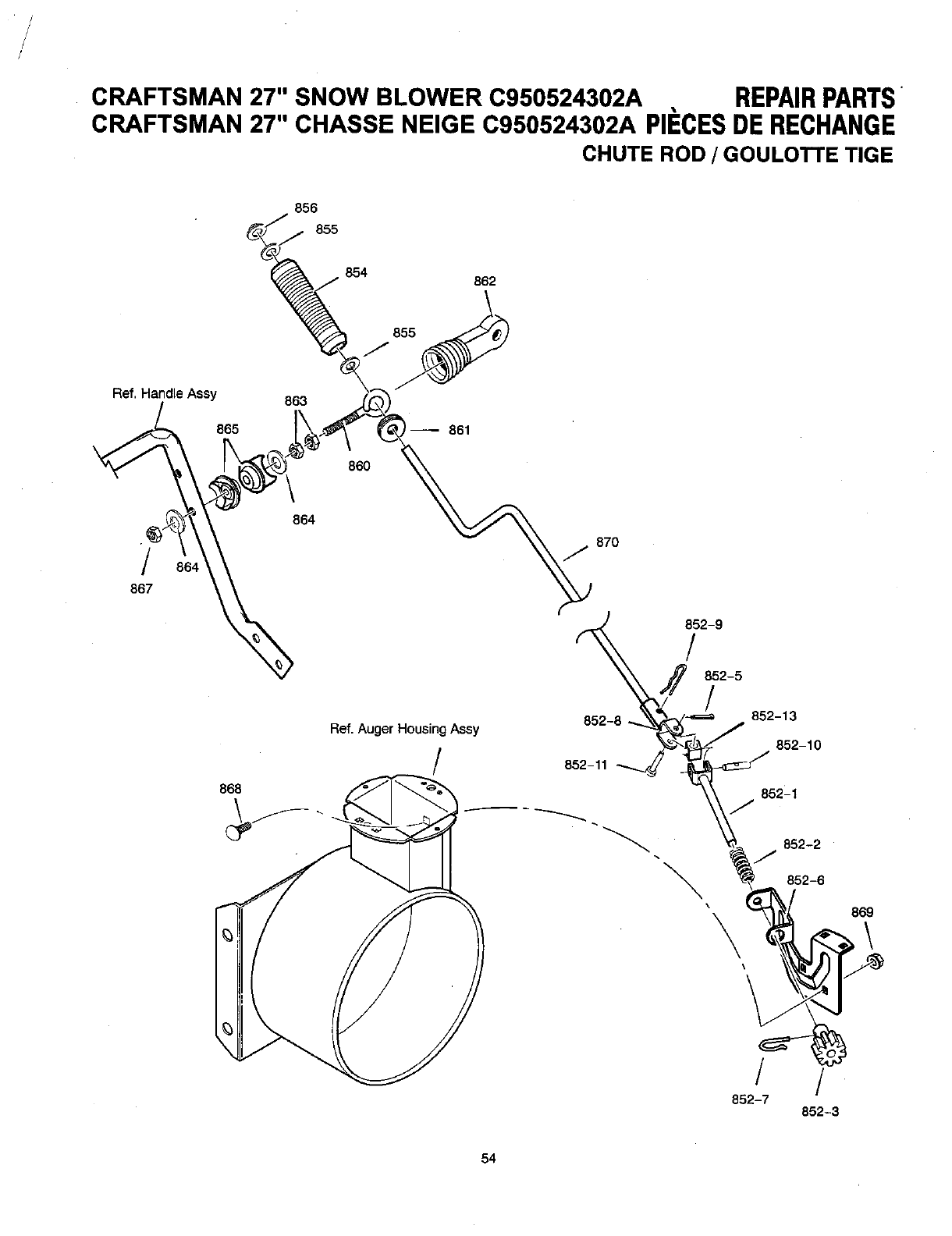
/
/
CRAFTSMAN 27" SNOW BLOWER C950524302A REPAIRPARTS
CRAFTSMAN 27" CHASSE NEIGE C950524302A PIECESDERECHANGE
CHUTE ROD /GOULOTTE TIGE
Ref, Handle Assy
/
867
856
855
854
855
J
865
863
860
864
Ref. Auger Housing Assy
/
862
870
852-8
852-11
852-9
/
852-5
/852-13
852-10
852-1
852-2
J
852-6
\
\
/ /
852-7 852-3
54
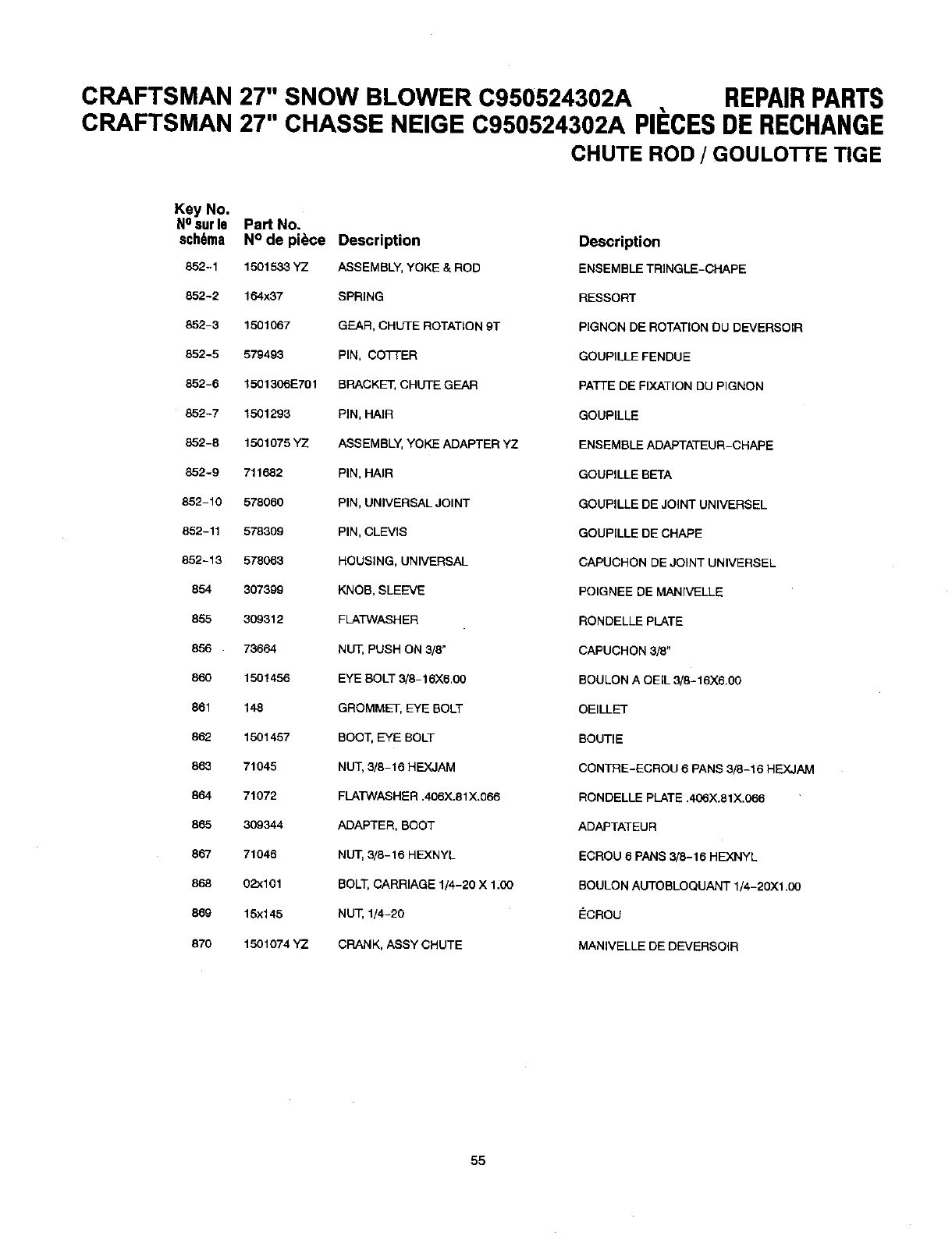
CRAFTSMAN 27" SNOW BLOWER C950524302A REPAIRPARTS
CRAFTSMAN 27" CHASSE NEIGE C950524302A PII_CESDE RECHANGE
CHUTE ROD /GOULO'R'E TIGE
Key No.
NOsurle Part No.
sch6ma N° de piece Description
852-1 1501533 YZ ASSEMBLY, YOKE & ROD
852-2 164x37 SPRING
852-3 1501057 GEAR, CHUTE ROTATION 9T
852-5 579493 PIN, CO77-ER
852-6 15013061:701 BRACKET, CHUTE GEAR
852-7 1501293 PIN, HAIR
852-8 1501075 YZ ASSEMBLY, YOKE ADAPTER YZ
852-9 711682 PIN, HAIR
852-10 578060 PIN, UNIVERSAL JOINT
852-11 578309 PIN, CLEVIS
852-13 578063 HOUSING, UNIVERSAL
854 307399 KNOB, SLEEVE
855 309312 FLATWASHER
856 73664 NUT, PUSH ON 3/8"
860 1501455 EYE BOLT 3/8-16)(6.00
861 148 GROMMET, EYE BOLT
862 1501457 BOOT, EYE BOLT
883 71045 NUT, 3/8-16 HEXJAM
864 71072 FLATWASHER .405X.81X.066
865 309344 ADAPTER, BOOT
867 71046 NUT, 3/8-15 HEXNYL
858 02x101 BOLT, CARRIAGE 1/4-20 X 1:00
869 15x145 NUT, 1/4-20
870 1501074 YZ CRANK, ASSY CHUTE
Description
ENSEMBLE TRINGLE-CHAPE
RESSORT
PIGNON DE ROTATION DU DEVERSOIR
GOUPILLE FENDUE
PATTE DE FIXATION DU PIGNON
GOUPILLE
ENSEMBLE ADAPTATEUR-CHAPE
GOUPILLE BETA
GOUPILLE DE JOINT UNIVERSEL
GOUPILLE DE CHAPE
CAPUCHON DE JOINT UNIVERSEL
POIGNEE DE MANIVELLE
RONDELLE PLATE
CAPUCHON 3/8"
BOULON A OEIL 3/8-18X5.00
OEILLET
BOUTIE
CONTRE-ECROU 6 PANS 3/8-15 HEX_JAM
RONDELLE PLATE .406X.81X.066
ADAPTATEUR
ECROU 6 PANS 3/8-15 HEXNYL
BOULON AUTOBLOQUANT 1/4-20X1.00
_CROU
MANIVELLE DE DEVERSOIR
55
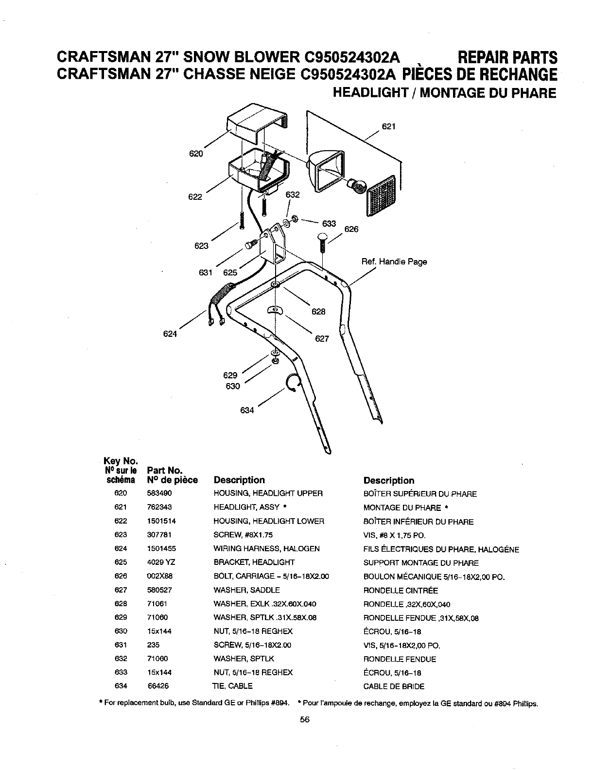
CRAFTSMAN 27" SNOW BLOWER C950524302A REPAIRPARTS
CRAFTSMAN 27" CHASSE NEIGE C950524302A PII_CESDERECHANGE
HEADLIGHT /MONTAGE DU PHARE
620
621
J
622
633 626
623
Ref, Handle Page
631 625
624
629
630 J
6,34
Key No.
NOsur le Part No.
sch6ma N° de piece Description
620 583490 HOUSING, HEADLIGHT UPPER
621 762343 HEADLIGHT, ASSY *
522 1501514 HOUSING, HEADLIGHT LOWER
623 307781 SCREW, #8X1,75
524 1501455 WIRING HARNESS, HALOGEN
625 4029 YZ BRACKET, HEADLIGHT
626 002X88 BOLT,CARRIAGE - 5/16-18)(2.00
527 580527 WASHER, SADDLE
528 71061 WASHER, EXLK .32X.60X.040
529 71060 WASHER, SPTLK .31X.58X,08
630 15x144 NUT, 5/16-18 REGHEX
631 235 SCREW, 5/16-18X2.CO
632 71060 WASHER, SPTLK
633 15x144 NUT, 5/16-18 REGHEX
634 66426 TIE, CABLE
Description
BOTTER SUPI_RIEUR DU PHARE
MONTAGE DU PHARE *
BO_TER INEERIEUR DU PHARE
VIS, #8 X 1,75 PO.
ElLS E_LECTRIQUES DU PHARE, HALOGF_NE
SUPPORT MONTAGE DU PHARE
BOULON M_CANIQUE 5/16-18X2,00 PO.
RONDELLE CINTRI_E
RONDELLE ,32X,60X,040
RONDELLE FENDUE ,31X,58X,08
_CROU, 5/16-18
VIS, 5/15-18X2,00 PO.
RONDELLE FENDUE
ECROU, 5/16-18
CABLE DE BRIDE
* Forreplacementbulb,useStandardGE orPhillips#894. * PourI'ampoulede rechange,employezla GE standardou #894 Phillips,
56
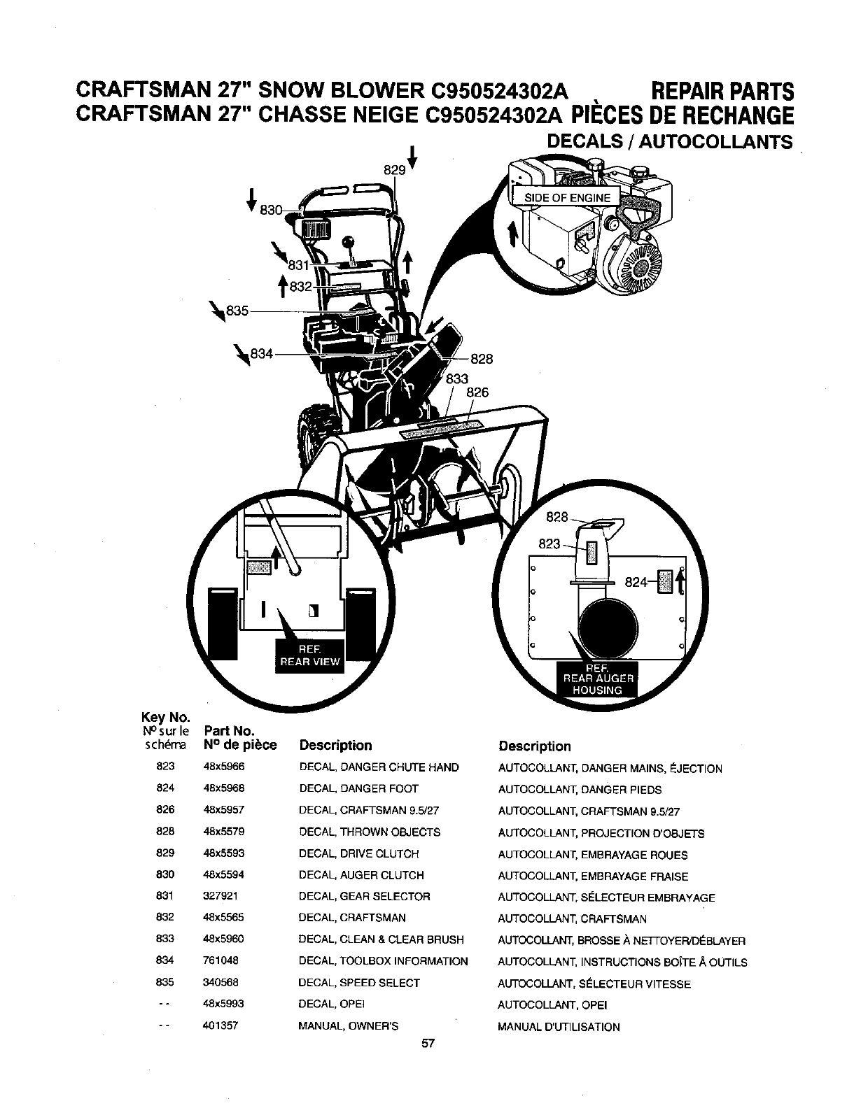
CRAFTSMAN 27" SNOW BLOWER C950524302A REPAIRPARTS
CRAFTSMAN 27" CHASSE NEIGE C950524302A PIECESDERECHANGE
DECALS /AUTOCOLLANTS
133
826
Key No.
N°sur le Part No.
schdma N° de piece
823 48x5966
824 48x5968
826 48x5957
828 48x5579
829 48x5593
830 48x5594
831 327921
832 48x5565
833 48x5960
834 761048
835 340568
-- 48x5993
-- 401357
Descri _tion
DECAL DANGER CHUTE HAND
DECAL DANGER FOOT
DECAL CRAFTSMAN 9.5/27
DECAL THROWN OBJECTS
DECAL DRIVE CLUTCH
DECAL AUGER CLUTCH
DECAL GEAR SELECTOR
DECAL CRAFTSMAN
DECAL CLEAN & CLEAR BRUSH
DECAL TOOLBOX INFORMATION
DECAL SPEED SELECT
DECAL OPEl
MANUAL, OWNER'S
57
Description
AUTOCOLLANT, DANGER MAINS, _JECTION
AUTOCOLLANT, DANGER PIEDS
AUTOCOLLANT, CRAFTSMAN 9.5/27
AUTOCOLLANT, PROJECTION D'OSJETS
AUTOCOLLANT, EMBRAYAGE ROUES
AUTOCOLLANT, EMBRAYAGE FRAISE
AUTOCOLLANT, SELECTEUR EMBRAYAGE
AUTOCOLLANT, CRAFTSMAN
AUTOCOLLANT, BROSSE A NETFOYER/DI_BLAYER
AUTOCOLLANT, INSTRUCTIONS BO/TE/_ OUTILS
AUTOCOLLANT, S_LECTEUR VITESSE
AUTOCOLLANT, OPEl
MANUAL D'UTILISATION
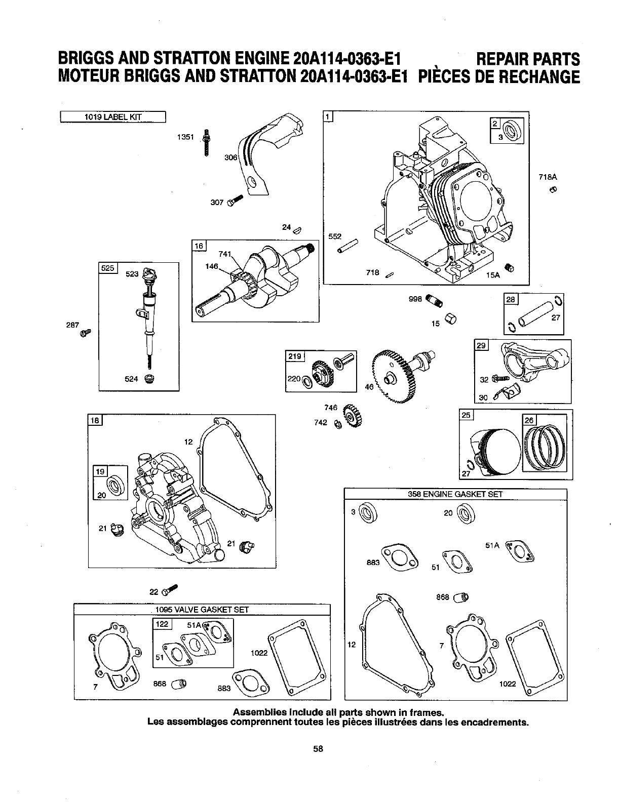
BRIGGSANDSTRATrONENGINE20A114-O363-E1 REPAIRPARTS
MOTEURBRIGGSANDSTRATrON20A114-O363.E1PIECESDERECHANGE
1019LABEL KIT ]
5251 523
287
524
1351 ,f
307
24_
741 _5_
748
718 _,
998
15
718A
1281
12
358 ENGINE GASKET SET
30 2°O
51A
12
Assemblies include all parts shown in frames,
Les assemblages comprennent toutes les pi_cee illustrdes dans les encadrements.
58
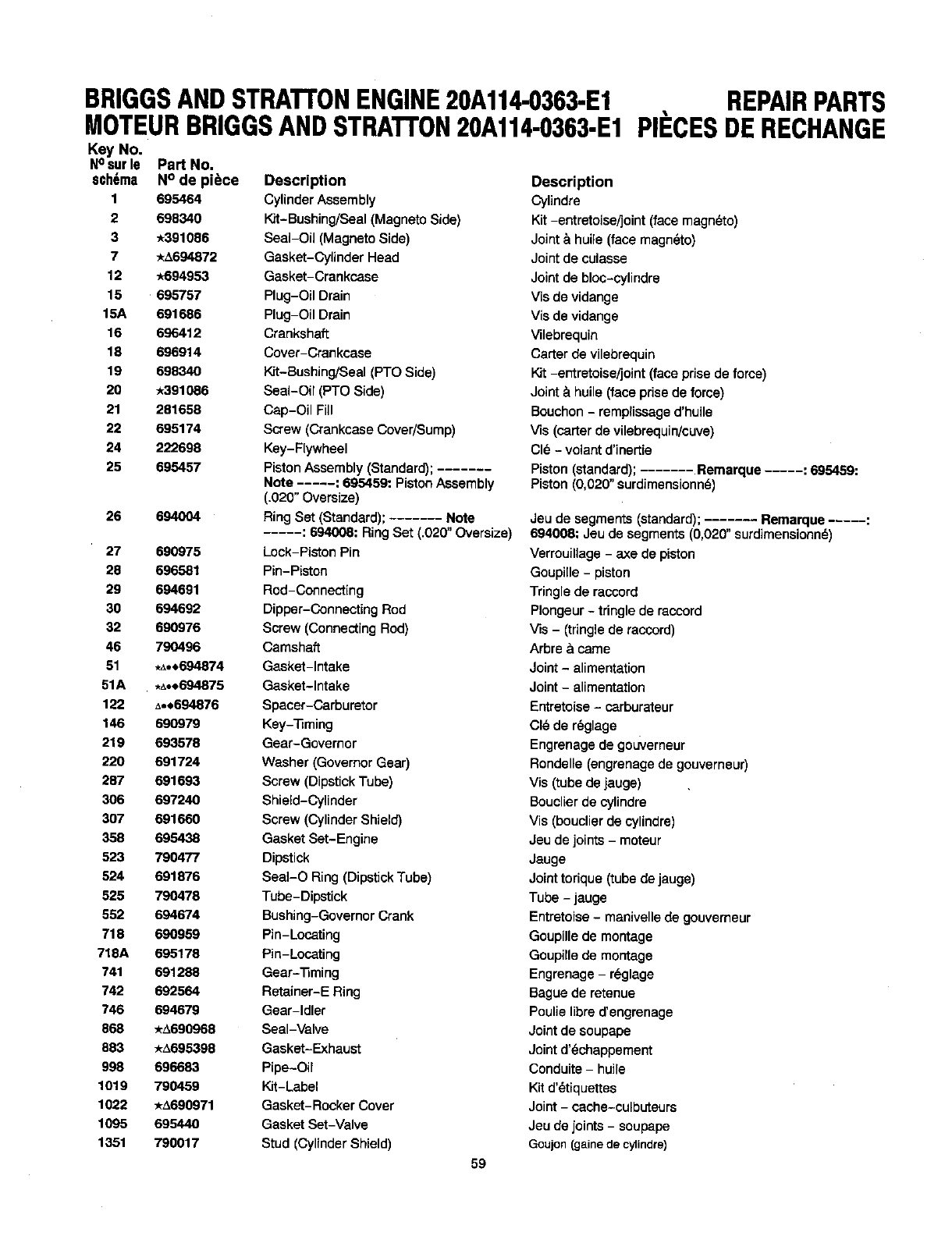
BRIGGSANDSTRAI"I'ONENGINE20A114-O363-E1
MOTEURBRIGGSANDSTRATTON20A114-O363-E1
Key No.
Nosurle Part No.
sch6ma N ° de piece Description
1 695464 Cylinder Assembly
2 698340 Kit-Bushing/Seal (Magneto Side)
3_391086 Seal-Oil (Magneto Side)
7 *_.694872 Gasket-Cylinder Head
12 *694953 Gasket-Crankcase
15 695757 Plug-Oil Drain
16A 691696 Plug-Oil Drain
16 696412 Crankshaft
18 696914 Cover-Crankcase
19 698340 Kit-Bushing/Seal (PTO Side)
20 _391086 Seal-Oil (PTO Side)
21 281658 Cap-Oil Fill
22 695174 Screw (Crankcase Cover/Sunlp)
24 222698 Key-Ftywheel
25 695457 Piston Assembly (Standard); .......
Note ..... : 695459: PistonAssembly
(,020" Oversize)
26 694004 Ring Set (Standard); ...... Note
..... : 694008: Ring Set (,020" Oversize)
27 690975 Lock-Piston Pin
28 696581 Pin-Piston
29 694691 Rod-Connecting
30 694692 Dipper-Connecting Rod
32 690976 Screw (Connecting Rod)
46 790496 Camshaft
51 ._._,694874 Gasket-_ntake
51A .,_ot694875 Gasket-Intake
122 Ao.694876 Spacar-Carburetor
146 690979 Key-_ming
219 693576 Gear-Governor
220 691724 Washer (Governor Gear)
287 691693 Screw (Dipstick Tube)
306 697240 Shield-Cylinder
307 691660 Screw (Cylinder Shield)
358 695438 Gasket Set-Engine
523 790477 Dipstick
524 691876 Seal-O Ring (DipstickTube)
625 790479 Tube-Dipstick
652 694674 Bushing-Governor Crank
718 690959 Pin-Locating
718A 695178 Pin-Locating
741 691288 Gear-'13ming
742 692564 Retainer-E Ring
746 694679 Gear-Idler
866 */`690969 Seal-Valve
683 */,695398 Gasket-Exhaust
998 696693 Pipe-Oil
1019 790459 Kit-Label
1022 */`690971 Gasket-Rocker Cover
1095 695440 Gasket Set-Valve
1351 790017 Stud (Cylinder Shield)
59
REPAIRPARTS
PIECESDERECHANGE
Description
Cylindre
Kit -entretoise/]oint (face nlagn_to)
Joint & huile (face nlagn_to)
Joint de culasse
Jointde bloc-cylindre
Vie de vidange
Vie de vidange
Vilebrequin
Carter de vilebrequin
Kit -entretoise/joint (face prise de force)
Joint &huile (face prise de force)
Bouchon - remplissage d'huile
Vie (carter de vilebrequin/ouve)
CI_,- volant d'inertie
Piston (standard); ....... Remarque ..... :695459:
Piston (0,020" surdimensionn_)
Jeu de segments (standard); ....... Remarque ..... :
694008: Jeu de segments (0,020" surdinlensionne)
VerrouiUage- axe de piston
Goupille - piston
Tringle de raccord
Plongeur - tringle de raccord
Us -(tringle de raccord)
Arbre & came
Joint- alinlentation
Joint - alinlentation
Entretoise - carburateur
CI_ de reglage
Engrenage de gouverneur
Rondelle (engrenage de gouverneur)
Vie (tube de jauge)
Bouctierde cyUndre
Vie (bouclierde cylindre)
Jeu de joints - meteur
Jauge
Jointtorique (tube de jauge)
Tube - jauge
Entretoise - manivelle de gouvenleur
GcupilLede nlontage
Goupille de montage
Engrenage - r_glage
Bague de retenue
Poulie libra d'engrenage
Joint de soupape
Joint d'_chappenlent
Conduits - huile
Kit d'_tiquettes
Joint - cache-culbuteurs
Jeu de joints - soupape
Goujon(gains decylindre)
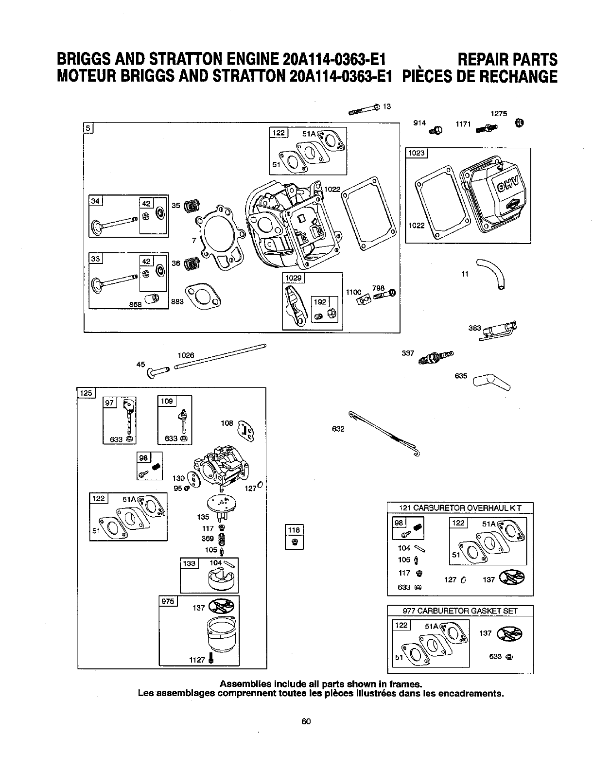
BRIGGSANDSTRATTONENGINE20A114-0363-E1 REPAIRPARTS
MOTEURBRIGGSANDSTRATrON20A114-0363-E1PII=CESDERECHANGE
1275
lO_
95 27 °
117
_S
105
1127_
632
121 CARBURETOR OVERHAUL KIT
_-_ 122 51A
105
117 127 O137 (_
633
977 CARBURETOR GASKET SET
OlA_'_ 1_7
Assemblies include all parts shown in frames,
Lee assemblages comprennent toutes lee pi_ces illustrdes dane lee encadrements.
6O
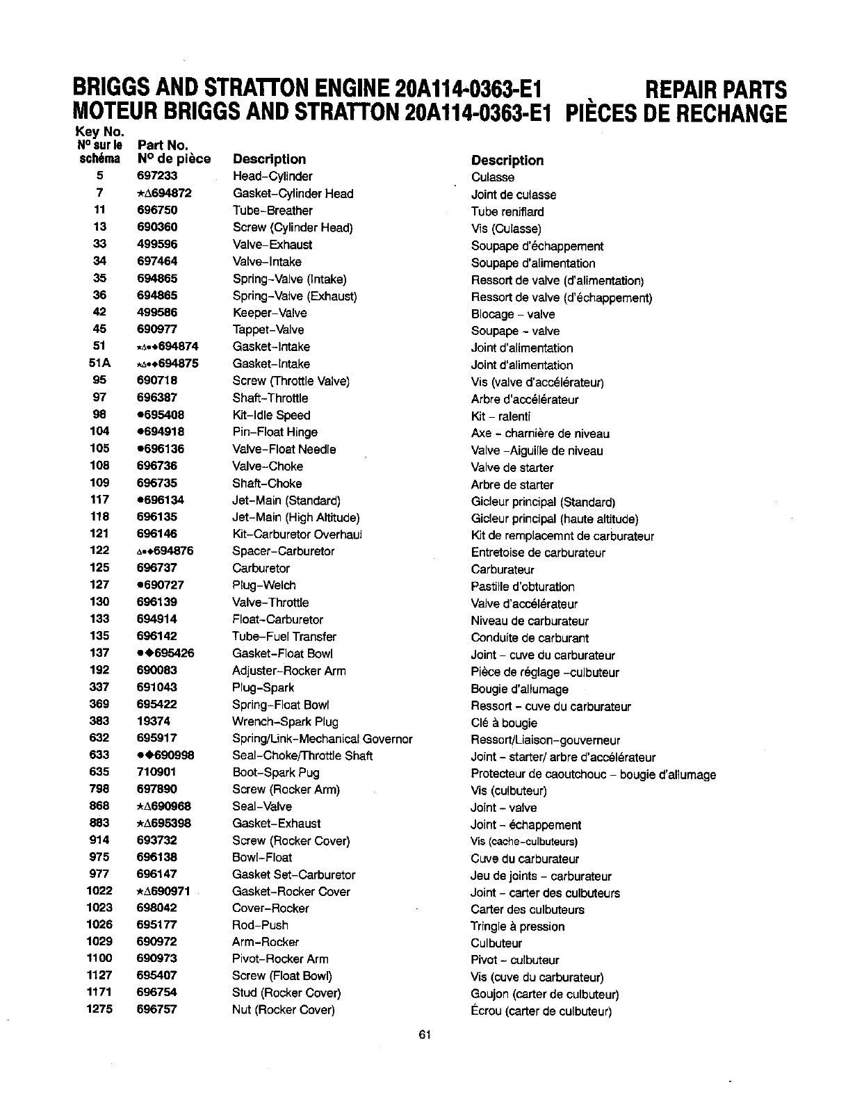
BRIGGSANDSTRATrONENGINE20A114.0363-E1
MOTEURBRIGGSANDSTRATTON20A114-O363-E1
Key No.
No sat le Part No.
sch6ma N° de piece Description
5 697233 Head-Cylinder
7*A694872 Gasket-Cylinder Head
11 696750 Tube-Breather
13 690360 Screw (cylinder Head)
33 499596 Valve-Exhaust
34 69-/464 Valve-intake
35 694865 Spring-Valve (Intake)
36 694866 Bprir_3-Valve (Exhaust)
42 499586 Keeper-Valve
45 690977 Tappet-Valve
51 ._o.694874 Gasket-Intake
51A ._°,694875 Gasket-Intake
95 690718 Screw (Throttle Valve)
97 696387 Shaft-Throttle
98 e695408 Kit-Idle Speed
104 e694918 Pin-Float Hinge
105 e696136 Valve-Fleet Needle
108 696736 Valve-Choke
109 696735 Shaft-Choke
117 e696134 Jet-Main (Standard)
118 696135 Jet-Main (High Altitude)
121 696146 Kit-Carburetor OverhauJ
122 t..$694876 Spacer-Carburetor
125 696737 Carburetor
127 e690727 Plug-Welch
130 696139 Valve-Thrott[e
133 694914 Float-Carburetor
135 696142 Tube-Fuel Transfer
137 e,695428 Gasket-Float Bowl
192 690083 Adjuster-Rocker Arm
337 691043 Plug-Spark
369 695422 Spring-Float Bowl
383 19374 Wrench-Spark Plug
632 695917 Spfi ng/Link-Mechanicat Governor
633 eN)690998 Seal-Choke/Throttle Shaft
635 710901 Boot-Spark Pug
798 697890 Screw (Rocker Arm)
868 _690968 Seal-Valve
883 *_,695398 Gasket-Exhaust
914 693732 Screw (Rocker Cover)
975 696138 Bowl-Float
977 696147 Gasket Set-Carburetor
1022 ./_690971 Gasket-Rocker Cover
1023 698042 Cover-Rocker
1026 695177 Rod-Push
1029 690972 Arm-Rocker
1100 690973 Pivot-Rocker Arm
1127 695407 Screw (Float Bowl)
1171 696754 Stud (Rocker Cover)
1275 696757 Nut (Rocker Cover)
REPAIRPARTS
PIECESDERECHANGE
61
Description
Culasse
Jointde culasse
Tube reniT']erd
Us (Culasse)
Soupape d'_chappernent
Soupapa d'alimentati_'_
Reesort de valve (d'alimentation)
Reesort de valve (d'6chappernent)
Blocage - valve
Soupape - valve
Joint d'alirnentation
Joint d'alirnentation
Vie (valve d'acc_l_rateur)
Arbre d'acc_l_rateur
Kit - ralenti
Axe - charni_re de niveau
Valve -Aiguille de niveau
Valve de starter
Arbre de starter
Gicleur principal (Standard)
Gicleur principal (haute altitude)
Kit de remplacernnt de carburateur
Entretoise de carburateur
Carburateur
Pastille d'obturation
Valve d'acc_l(.=rateur
Niveau de carburateur
Conduite de carburant
Joint - cuve du carburateur
Piece de r_glage -culbuteur
Bougie d'allumage
Ressort - cuve du carburateur
CI_ & bougie
Ressort!Lialeon-geuverneur
Joint - started arbre d'accel_rateur
Protecteur de caoutchouc- bougie d'allumage
Vie (culbuteur)
Joint - valve
Joint - L=chappement
Vie (¢ache-culbuteurs)
CLIVedu carburateur
Jeu de joints - carburateur
Joint - carter des culbuteurs
Carter des culbuteurs
Tfingle & pression
Culbuteur
Pivot - culbuteur
Vie (cuve du carburateur)
Goujon (carter de cuibuteur)
I_crou (carter de culbuteur)
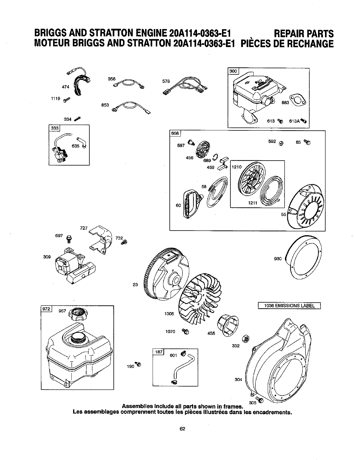
BRIGGSANDSTRATTONENGINE20A114-0363-E1 REPAIRPARTS
MOTEURBRIGGSANDSTRA'I'FON20A114.0363-E1PIECESDERECHANGE
1119
334
333
309
69,_ ,%
23
613
6_J
597_
'°° %0G 12"
s92_ 65
1211
55
19o"_i_
1005
1070
1036 EMISSIONS LABEL ]
@
832
304
d
30_
Assemblies Include all pa,rts shown in frames.
Les assemblages comprennent toutes les pieces illustrdes dans les encadrements.
62
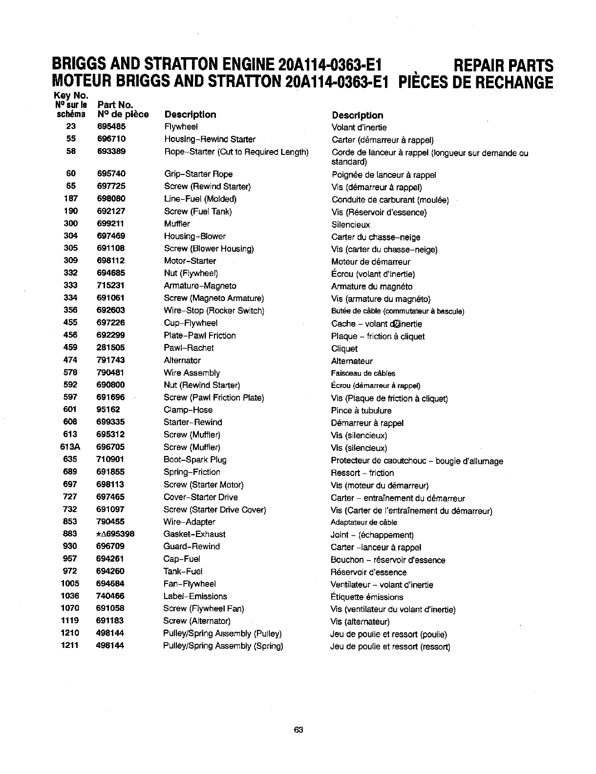
BRIGGSANDSTRATTONENGINE20A114-O363-E1
MOTEURBRIGGSANDSTRATrON20A114.0363-E1
Key No,
NOsur le Part No.
$ch6ma N° de pl_ce Description
23 695485 Flywheel
55 696710 Housing-RewindStarter
58 693389 Rope-Starter(Cutto RequiredLengtPi)
60 695740 Grip-Starter Rope
65 697725 Screw (Rewind Starter)
187 698080 Line-Fuel (Molded)
190 692127 Screw (Fuel Tank)
300 699211 Muffler
304 697469 Housing-Blower
305 691108 Screw (Blower Housing)
309 698112 Motor-Starter
332 694685 Nut (Flywheel)
333 715231 Armature-Magneto
334 691061 Screw (Magneto Armature)
356 692603 Wire-Stop (Rocker Switch)
455 697226 Cup-Flywheel
456 692299 Plate-Pawl Friction
459 281505 PawI-Rachet
474 791743 Alternator
578 790481 Wire Assembly
592 690800 Nut (Rewind Starter)
597 691696 Screw (Pawl FrictionPlate)
601 95162 Clamp-Hose
608 699335 Starter-Rewind
613 695312 Screw (Muffler)
613A 696705 Screw (Muffler)
635 710901 Boot-Spark Plug
689 691855 Spring-Friction
697 698113 Screw (Starter Motor)
727 697465 Cover-Starter Drive
732 691097 Screw (Starter Drive Cover)
853 790455 Wire-Adapter
883 *t,695398 Gasket-Exhaust
930 696709 Guard-Rewind
957 694261 Cap-Fuel
972 694260 Tank-Fuel
1005 694684 Fan-Flywheel
1036 740466 Label-Emissions
1070 691058 Screw (Flywheel Fan)
1119 691183 Screw (Alternator)
1210 498144 Pulley/SpringAssembly (Pulley)
1211 498144 Pulley/SpringAssembly (Spring)
REPAIRPARTS
PII=CESDERECHANGE
Description
Volant d'inertie
Carter (d_marreur _.rappel)
Corde de lanceur _rappel (Iongueursur demande ou
standard)
Poign_e de lanceur & rappel
Vis (d_marreur & rappel)
Conduite de carburant (moul_e)
Vis (Reservoir d'eseenoe)
Silencieux
Carter du chasse-neige
Vis (carter du chasse-neige)
Moteur de d_marreur
€:crou (volant d'iner[ie)
Armature du magneto
Vis (armature du magneto)
Butte de c&ble(commutateur,_bascule)
Cache - volant d_inertie
Plaque - friction &cliquet
Cliquet
Alternateur
Faisceaudec&b[es
I_crou(d_marreur& rappel)
VLs(Ptaque de friction _cliquet)
Pince & tubulure
D_marreur & rappel
Via (si_encieux)
Vis (silencieux)
Protecteur de caoutchouc - bougie d'allumage
Ressort -friction
Vis (moteur du d_marreur)
Carter - entra_nement du d6marreur
_s (Carter de I'entrainement du d_marreur)
Adaptateurde c&ble
Joint - (_chappement)
Carter -lancaur & rappel
Bouchon - r_servoir d'essence
R_servoir d'essence
Venti]ateur - volant d'inertie
€:tiquette _missions
Vis (ventilateur du volant d'inertie)
Vis (alternateur)
Jeu de poulie et ressort (poulie)
Jeu de poulie et ressort (ressort)
63
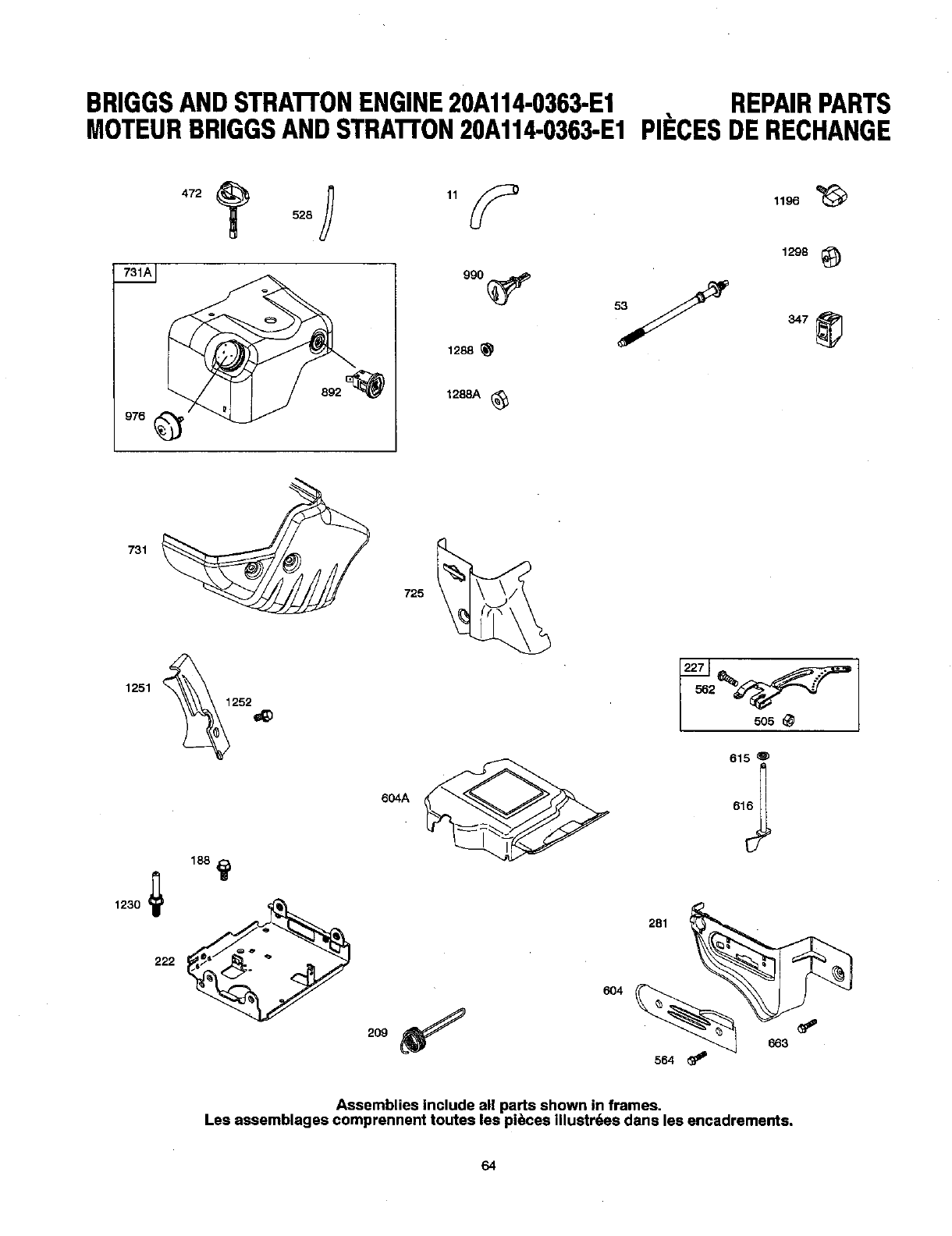
BRIGGSANDSTRA'I-I'ONENGINE20A114-0363-E1 REPAIRPARTS
MOTEURBRIGGSANDSTRA'I-rON20A114.0363-E1PIIECESDERECHANGE
976
472 o28 ,19
892_
1288
1288A (_
1196
1298 _)
731
725
222
604A
2o9_
6O4
615 O
564
Assemblies include all parts shown in frames.
Les assemblages comprennent toutes les pi_ces illustrdes dana les encadrements,
64
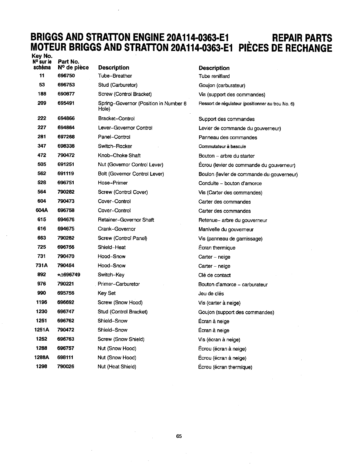
BRIGGSANDSTRATrONENGINE20A114-0363-E1
MOTEURBRIGGSANDSTRATrON20A114-0363-E1
Key No.
NOsur le Part No.
sch6ma N° de piece Description
11 696750 Tube-Breather
53 696753 Stud (Carburetor)
188 690877 Screw (Cordrol Bracket)
209 695491 Spring-Governor (Positionin Number 6
Hole)
222 694866 Bracket-Control
227 694864 Lever-Governor Control
281 697268 Panel-Control
347 698338 Switch-Rocker
472 790472 Knob-Choke Shaft
505 691251 Nut (Governor Control Lever)
562 691119 Bolt (Governor Control Lever)
528 696751 Hose-Primer
564 790282 Screw (Control Cover)
604 790473 Cover-Control
604A 696758 Cover-Control
615 694676 Retainer-Governor Shaft
616 694675 Crank-Governor
663 790282 Screw (Control Panel)
725 696756 Shield-Heat
731 790470 Hood-Snow
731A 790454 Hood-Snow
892 *A696749 Switch-Key
976 790221 Primer-Carburetor
990 695756 Key Set
1196 696692 Screw (Snow Hood)
1230 696747 Stud (ControlBracket)
1251 696762 Shield-Snow
1251A 790472 Shield-Snow
1252 696763 Screw (Snow Shield)
1268 696757 Nut (Snow Hood)
1288A 698111 Nut (Snow Hood)
1298 790026 Nut (Heat Shield)
REPAIRPARTS
PIP'CESDERECHANGE
Description
Tube reniflard
Goujon (carburateur)
Vis (support des commandes)
Ressortde rdgulateur(positionnerautrouNo.6)
Support des commandes
Levier de commande du gouverneur)
Panneau des commandes
Commutateur_ibascule
Bouton - arbre du starter
€:crou (levier de commande du gouverneur)
Boulon (levier de commande du gouverneur)
Conduite - boutond'amorce
Vis (Caner des commandes)
Carter des commandes
Carter des commandes
Retenue- arbre du gouverneur
Man[velle du gouverneur
Vis (panneau de gamissage)
Ecran thermique
Carter - neige
Caner - neige
Cle de contact
Boutond'amorce -carburateur
Jeu de c[_s
Vis (carter &neige)
Goujon (supportdes commandes)
I_cran & neige
Ecran &neige
Vis (_cran _.neige)
Ecrou (dcran &neige)
€:crou (_cran &neige)
I_crou (_cran thermique)
65

NOTES
66

NOTES
67
Just Call:
1-800-4-MY-HOME ®
(1-800-469-4663)
24 hours a day, 7 days a week
For the repair of major brand appliances in your own home ...
no matter who made it, no matter who sold it!
For your nearest Sears Parts & Service location,
to bring in products like vacuums, lawn equipment and electronics.
For Sears Parts & Service, to order the replacement parts,
accessories and owner's manuals that you need to do-it-yourself.
www.sears.ca
To purchase or inquire about a Sears Maintenance Agreement, call:
1-800-361-6665
9 a.m. - 8 p.m. Mon. - Fri. EST, 9 a.m. - 4 p.m. Sat.
Pour service en francais:
1-800-LE-FOYER Mc
(1-800-533-6937)
www.sears.ca
HomeCentrar
'_rM Trademarks of Sears, Roebuck and Co. used under license by Sears Canada
®MC
Marque depos_e/ Marque de commerce de Seam, Roebuck and Co. utilisde en vertu d'une licence de Sears Canada
68
