Craftsman 10 Single Bevel Sliding Compound Miter Saw 21237 Owners Manual
Craftsman-137-21237-Users-Manual-161071 craftsman-137-21237-users-manual-161071
137212370 137212370 CRAFTSMAN COMPOUND MITER SAW - Manuals and Guides L0703055 View the owners manual for your CRAFTSMAN COMPOUND MITER SAW #137212370. Home:Tool Parts:Craftsman Parts:Craftsman COMPOUND MITER SAW Manual
CRAFTSMAN Miter Saw Manual L0703055 CRAFTSMAN Miter Saw Owner's Manual, CRAFTSMAN Miter Saw installation guides
13721237 3bceab57-6053-42a1-807c-dd140c725bdf Craftsman Saw 137.21237 User Guide |
2015-03-28
: Craftsman Craftsman-10-Single-Bevel-Sliding-Compound-Miter-Saw-21237-Owners-Manual-661112 craftsman-10-single-bevel-sliding-compound-miter-saw-21237-owners-manual-661112 craftsman pdf
Open the PDF directly: View PDF ![]() .
.
Page Count: 30

Operator's Manual
CRSFrSMSN°
10 in. SLiDiNG COMPOUND
MITER SAW WiTH LASER TRAC ®
Model No. 137.212370
CAUTION:
Before using this Miter Saw,
read this manual and follow
all its Safety Rules and
Operating instructions
• Safety Instructions
• installation
• Operation
• Maintenance
eParts List
Customer Help Line
For Technical Support
1-800-843-1682
Sears Parts &
Repair Center
1-800-488-1222
Sears, Roebuck and Co., Hoffman Estates, IL 60179 USA
Visit our Craftsman website: www.sears.condcraftsman
Part No. 137212370001
S ECTION PAG E
Warranty ............................................................ 2
Product Specifications ........................................ 2
Power Tool Safety .............................................. 3
Sliding Compound Miter Saw Safety ................... 4
Electrical Requirements and Safety .................... 4
Accessories and Attachments ............................ 6
Tools Needed for Assembly ................................ 6
Carton Contents .................................................. 7
SECTION PAGE
Know Your Sliding Compound Miter Saw ..... 8
Glossary of Terms ......................................... 9
Assembly ...................................................... 10
Adjustments .................................................. 14
Operat ion ...................................................... 16
Maintenance ................................................. 24
Troubleshooting Guide ................................. 25
Parts List ....................................................... 26
ONE-YEAR FULL WARRANTY ON CRAFTSMAN TOOL
If this Craftsman tool fails due to a defect in material or workmanship within one year from the date of purchase,
CALL 1-800-4-MY-HOME(_TO ARRANGE FOR FREE REPAIR (or replacement if repair proves impossible).
If this tool is used for commercial or rental purposes, this warranty will apply for only ninety days from the date of
purchase. This warranty applies only while this tool is in the United States.
This warranty gives you specific legal rights, and you may also have other rights, which vary, from state to state.
Sears, Roebuck and Co., Hoffman Estates, IL 60179
A WARNINGI
Some dust created by power sanding, sawing, grinding, drilling and other construction activities contains
chemicals known to cause cancer, birth defects or other reproductive harm. Some examples of these
chemicals are:
=Lead from lead-based paints
•Crystalline silica from bricks, cement and other masonry products
•Arsenic and chromium from chemically treated lumber
Your risk from these exposures varies, depending on how often you do this type of work. To reduce your
exposure to these chemicals, work in a well ventilated area and work with approved safety equipment such as
dust masks that are specially designed to filter out microscopic particles.
MOTOR MITER SAW
Power Source .......................... 120',/AC, 60Hz, 15 Amp Cutting Capacity:
Arbor Shaft Size .................... 5/8 in. Crosscut ................................... 3-&/8 in. x 12 in.
Speed ...................................... 4800 RPM (No load) Miter 45 ° R. & L ........................ 3-5/8 in. x 8 in.
Brake ....................................... Electric Bevel 45 ° L ............................... 1-&/8 in. x 12 in.
Double Insulated ..................... Yes 45° Miter and 45 ° Bevel ............ 1-5/8 in. x 8 in.
MITER SAW BLADE
Rotating Table: Diameter ................................... 10 in.
Miter Detent Stops ................... 0o,15°, 22.5°, 31.6°, 45° R & L Arbor ....................................... 5/8 in.
Bevel Positive Stops ................ 0°, 33.9 °, 45° L
Extension Wings ...................... Yes
[A WARNINGI
To avoid electrical hazards, fire hazards or damage to the tool, use proper circuit protection.
This tool is wired at the factory for 110=120 Volt operation. It must be connected to a110-120 Volt /15 Ampere
time delay fuse or circuit breaker. To avoid shock or fire, replace power cord immediately if it is worn, cut or
damaged in any way.
Before using your tool, it is critical that you read and understand these safety rules. Failure to follow these
rules could result in serious injury to you or damage to the tool.

GENERAL SAFETY iNSTRUCTiONS
Read and understand all the instructions below
before using the power tool. These safety
instructions are not meant to cover every possible
condition that could occur. As with any power tool,
common sense, vigilance and due care must be
used.
I.
2.
3.
4,
READ and become familiar with the entire
Operator's Manual. LEARN the tool's applicationl
limitations and possible hazards.
KEEP GUARDS IN PLACE and in working order.
REMOVE ADJUSTING KEYS AND WRENCHES.
Form the habit of checking to see that keys and
adjusting wrenches are removed from the tool
before turning ON.
KEEP WORK AREA CLEAN, Cluttered areas and
benches invite accidents.
5. DO NOT USE iN DANGEROUS ENVIRONMENTS.
Do not use power tools in damp locations or expose
them to rain or snow. Keep work area well lit.
6. KEEP CHILDREN AWAY. All visitors and bystanders
should be kept at a safe distance from work area.
7. MAKE WORKSHOP CHILDPROOF with padlocks;
master switches or by removing starter keys.
8. DO NOT FORCE THE TOOL. It will do the job
better and is safer if used at the rate for which it was
designed.
9. USE THE RIGHT TOOL. Do not force the tool or an
attachment to do a job for which it was not designed.
I 0. USE PROPER EXTENSION CORDS. Make sure
your extension cord is in good condition. When
using an extension cord, be sure to use one heavy
enough to carP;/the current your product will draw.
An undersized cord will result in a drop in line
voltage and in loss of power that will cause the tool
to overheaL The table on page 5 shows the correct
size to use depending on cord length and nameplate
ampere rating. If in doubt, use the next heavier
gauge. The smaller the gauge number, the heavier
the cord.
11. WEAR PROPER APPAREL. Do not wear loose
clothing, gloves, neckties, rings, bracelets or other
jewelry that may get caught in moving parts. Non-
slip footwear is recommended. Wear protective hair
covering to contain long hair.
12. ALWAYS WEAR EYE PROTECTION. Any power
tool can throw debris into the eyes and could cause
permanent eye damage. ALWAYS wear Safety
Goggles (not glasses) that comply with ANSI Safety
standard Z87.1. Everyday eyeglasses
have only impact-resistant lenses. They ARE NOT
safety glasses. NOTE: Glasses or goggles not in
compliance with ANSI Z87.1 could cause serious
injury.
13. WEAR A FACE MASK OR DUST MASK, Sawing
operation produces dust.
14. SECURE WORK. Use clamps or a vise to hold work
when practical. It's safer than using your hand, and
it frees both hands to operate the tool.
15. DISCONNECT TOOLS FROM POWER SOURCE
before servicing and when changing accessories,
such as blades, bits and cutters.
16. REDUCE THE RISK OF UNINTENTIONAL
STARTING. Make sure switch is in the OFF position
before plugging in the tool.
17. USE RECOMMENDED ACCESSORIES. Consult
this Operator's Manual for recommended
accessories. The use of improper accessories may
cause injury to yourself or others.
18. NEVER STAND ON THE TOOL. Serious injury.
could occur if the tool is tipped or if the cutting tool
is unintentionally contacted.
19. CHECK FOR DAMAGED PARTS. Check for
alignment of moving parts, binding of moving
parts, breakage of parts, mounting and any other
conditions that may affect its operation. A guard
or other part that is damaged should be properly
repaired or replaced.
20. NEVER LEAVE THE TOOL RUNNING
UNATTENDED. TURN THE POWER OFF. Do not
walk away from a running tool until the blade comes
to a complete stop, and then unplug the unit.
21. DO NOT OVERREACH, Keep proper footing and
balance at all times.
22. MAINTAIN TOOLS WITH CARE, Keep tools
sharp and clean for best and safest performance.
Follow instructions for lubricating and changing
accessories.
23. DIRECTION OF FEED. Feed work into a blade or
cutter against the direction or rotation of the blade or
cutter.
24. WARNING: Dust generated from certain materials
can be hazardous to your health. Always operate
the saw in a well-ventilated area and provide for
proper dust removal.
25. DO NOT loan your tool to another person without
providing him/her with the Operator's Manual.
Be sure he/she learns the tools applications and
possible hazards,
3
I. IMPORTANT:DO NOT USE THIN KERF BLADES.
They can deflect and contact the blade guard and
cause possible in]ury to the operator.
2. DO NOT operate the miter saw until it is completely
assembled and installed according to these
instructions.
3. IF YOU ARE NOT thoroughly familiar with the
operation of miter saws, seek guidance from your
supervisor, instructor or other qualified person.
4. ALWAYS hold the work firmly against the fence and
table. DO NOT perform any operation freehand (use
clamp wherever possible).
5. KEEP HANDS out of the path of the saw blade. If
the workpiece you are cutting would cause your
hands to be within 7-1/2 in. of the saw blade, the
workpiece should be clamped in place before
making the cut.
6. MAKE SURE the blade is sharp, runs freely and is
free of vibration.
7. ALLOW the motor to come up to full speed before
starting a out.
8. KEEP THE MOTOR AIR SLOTS CLEAN and free
of chips or dust.
9. ALWAYS MAKE SURE all handles are tight before
cutting, even if the table is positioned in one of the
positive stops.
I 0. MAKE SURE both the blade and the collar are clean
and the arbor bolt is tightened securely=
11. USE only blade collars specified for your saw.
12. NEVER use blades larger than I 0 in. in diameter.
13. NEVER apply lubricants to the blade when the saw
is running.
14. ALWAYS check the blade for cracks or damage
before operation. Replace a cracked or damaged
blade immediately.
15. NEVER use blades recommended for operation at
less than 4800 rpm
16. ALWAYS keep the blade guards in place and use at
all times.
! 7. NEVER reach around the saw blade=
18. MAKE SURE the blade is not in contact with the
workpiece before the switch is turned ON.
I9. iMPORTANT: ,After completing a cut, release the
trigger switch and wait for the blade to stop before
returning the saw to the raised position.
20. MAKE SURE the blade has come to a complete
stop before removing or securing the workpiece,
changing the workpiece angle or changing the angle
of the blade.
21. NEVER cut metals or masonry products with this
tool. This miter saw is designed for use on wood
and wood=like products.
22. NEVER cut small pieces. If the workpiece being cut
would cause your hand or fingers to be within 7-1/2
in. of the saw blade, the workpiece is too small.
23. PROVIDE adequate support to the sides of the saw
table for long workpieces.
24. NEVER use the miter saw in areas with flammable
liquids or gases.
25. NEVER use solvents to clean plastic parts. Solvents
could possibly dissolve or otherwise damage the
material.
26. SHUT OFF the power before servicing or adjusting
the tool.
27. DISCONNECT the saw from the power source and
clean the machine when finished using.
28. MAKE SURE the work area is clean before leaving
the machine.
29. SHOULD any part of your miter sat,, become
missing, damaged, fail in any way or any electrical
component fail to perform properly, shut off the
switch and remove the plug from the power supply
outlet. Replace missing, damaged or failed parts
before resuming operation.
[,_ WARNING J
POWER SUPPLY AND MOTOR SPECIFICATIONS
The AC motor used in this saw is a universal,
nonreversible type. See "MOTOR" in the "PRODUCT
SPECIFICATIONS" section on page 2.
To avoid electrical hazards, fire hazards or damage to
the tool, use proper circuit protection. Your saw is wired
at the factory for 120 V operation. Connect to a 120 V
circuit. This circuit must not be less than a #I 2 wire with
a 20 A time-lag fuse or a #14 wire with a 15 A time-lag
fuse. To avoid shock or fire, if power cord is worn or cut,
or damaged in any way, have it replaced immediately.
4
ELECTRICAL REQUIREMENTS -cont'd
DOUBLE INSULATED []
The power tool is double insulated to provide a double
thickness of insulation between you and tool's electrical
system. All exposed metal parts are isolated from
the internal metal motor components with protecting
insulation:
Replacement parts - When servicing use only identical
replacement parts.
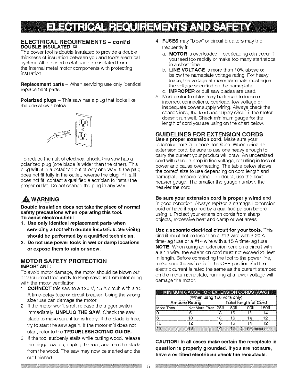
Polarized plugs = This saw has a plug that looks like
the one shown below:
To reduce the risk of electrical shock, this saw has a
polarized plug (one blade is wider than the other). This
plug will fit in a polarized outlet only one way. If the plug
does not fit fully in the outlet, reverse the plug. If it still
does not fit, contact a qualified electrician to install the
proper outlet. Do not change the plug in any way.
4. FUSES may "blow" or circuit breakers may trip
frequently if:
a. MOTOR is overloaded - overloading can occur if
you feed too rapidly or make too many start/stops
in a short time.
b. LINE VOLTAGE is more than 10% above or
below the nameplate voltage rating. For heavy
loads, the voltage at motor terminals must equal
the voltage specified on the nameplate.
c. IMPROPER or dull saw blades are used.
5. Most motor troubles may be traced to loose or
incorrect connections, overload, low voltage or
inadequate power supply wiring. Always check the
connections, the load and supply circuit if the motor
doesn't run well. Check minimum gauge for the
length of cord you are using on the chart below.
GUIDELINES FOR EXTENSION CORDS
Use a proper extension cord Make sure your
extension cord is in good condition. When using an
extension cord, be sure to use one hea W enough to
carp/the current your product will draw. An undersized
cord will cause a drop in line voltage, resulting in loss of
power and cause overheating. The table below shows
the correct size to use depending on cord length and
nameplate ampere rating. If in doubt, use the next
heavier gauge. The smaller the gauge number, the
heavier the cord.
[A WARNINGI
Double insulation does not take the place of normal
safety precautions when operating this tool.
To avoid electrocution:
1. Use only identical replacement parts when
servicing atool with double insulation. Servicing
should be performed by a qualified technician.
2. Do not use power tools in wet or damp locations
or expose them to rain or snow.
MOTOR SAFETY PROTECTION
IMPORTANT:
To avoid motor damage, the motor should be blown out
or vacuumed frequently to keep sawdust from interfering
with the motor ventilation.
1. CONNECT this saw to a 120 V, 15 A circuit with a 15
A time-delay fuse or circdt breaker. Using the wrong
size fuse can damage the motor.
2. If the motor won't start, release the trigger switch
immediately. UNPLUG THE SAW. Check the saw
blade to make sure it turns freely. If the blade is free,
try to start the saw again. If the motor still does not
start, refer to the TROUBLESHOOTING GUIDE.
3. If the tool suddenly stalls while cutting wood, release
the trigger switch, unplug the tool, and free the blade
from the wood. The saw may now be started and the
cut finished.
Be sure your extension cord is properly wired and
in good condition. Always replace a damaged extension
cord or have it repaired by a qualified person before
using it. Protect your extension cords from sharp
objects, excessive heat and damp or wet areas.
Use aseparate electrical circuit for your tools. This
circuit must not be less than a #I 2 wire with a 20 A
time-lag fuse or a #14 wire with a 15 A time-lag fuse.
NOTE: When using an extension cord on a circuit with
a # 14 wire, the extension cord must not exceed 25 feet
in length. Before connecting the tool to the power line,
make sure the switch is in the OFF position and the
electric current is rated the same as the current stamped
on the motor nameplate, running at a lower voltage will
damage the motor.
•_ = e = = Q O=lJ =
(When usng 120 volts only)
Ampere Rating Total length of Cord
MoreThan NotMoreThan 25ft. 50ft. 100ft. 150ft.
0 6 18 16 16 14
6 10 18 16 14 12
10 12 16 16 14 12
CAUTION: In all cases make certain the receptacle in
question is properly grounded. If you are not sure,
have a certified electrician check the receptacle.
5
RECOMMENDED ACCESSORIES
[AWARNING[
• Use only accessories recommended for this
miter saw. Follow instructions that accompany
accessories. Use of improper accessories may
cause hazards.
•The use of any cutting tool except 10 inch saw
blades which meet the requirements under
recommended accessories is prohibited. Do
not use accessories such as shaper cutters or
dado sets. Ferrous metal cutting and the use of
abrasive wheels is prohibited.
=Do not attempt to modify this tool or create
accessories not recommended for use with
this tool. Any such alteration or modification is
misuse and could result in a hazardous condition
leading to possible serious injury.
ACCESSORIES
Visit your Sears Hardware Department or see the
Sears Power and Hand Tool Catalog to purchase
recommended accessories for this power tool.
[_IL WARNING I
To avoid the risk of personal injury, do not modify this
power tool or use accessories not recommended by
Sears.
[_IL WARNING I
Read warnings and conditions on your CARBIDE TIPPED
SAW BLADE. Do not operate the saw without the proper
saw blade guard in place. Carbide is avery hard but
brittle material Care should be taken while mounting,
using and storing carbide tipped blades to prevent
accidental damage. Slight shocks, such as striking the
tip while handling, can seriously damage the blade.
Foreign objects in the workpiece, such as wire or nails,
can also cause tips to crack or break off. Before using,
always visually examine the blade and tips for bent
blade, cracks, breakage, missing or loose tips, or other
damage. Do not use if damage is suspected. Failure
to heed safety instructions and warnings can result in
serious bodily injury.
Supplied
Blade Wrench
Not supplied
...............................
Adjustable Wrench
Hex Key
Combination Square
Phillips Screwdriver
Slotted Screwdriver
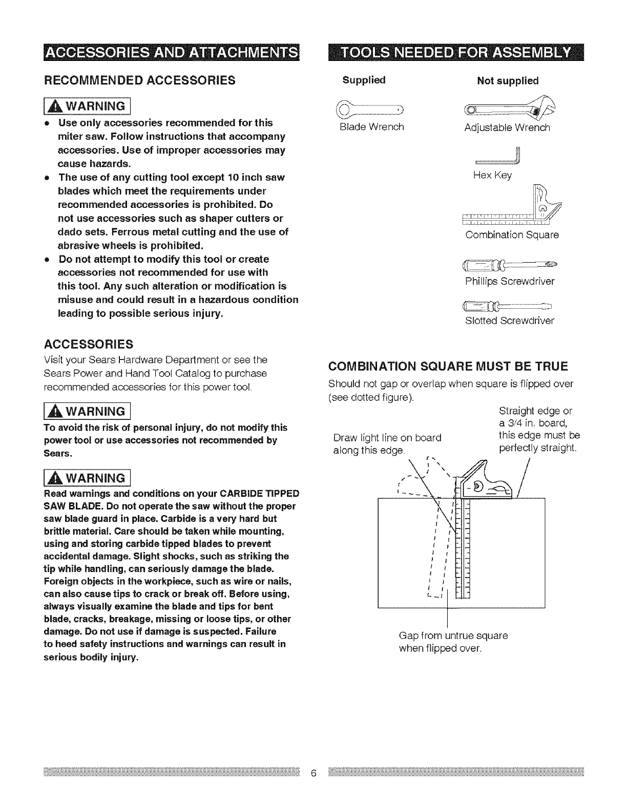
COMBINATION SQUARE MUST BE TRUE
Should not gap or overlap when square is flipped over
(see dotted figure).
Straight edge or
a 3,/4 in. board,
this edge must be
perfectly straight.
Draw light line on board
along this edge. r_
t
f
I
t
Gap from untrue square
when flipped over.
6
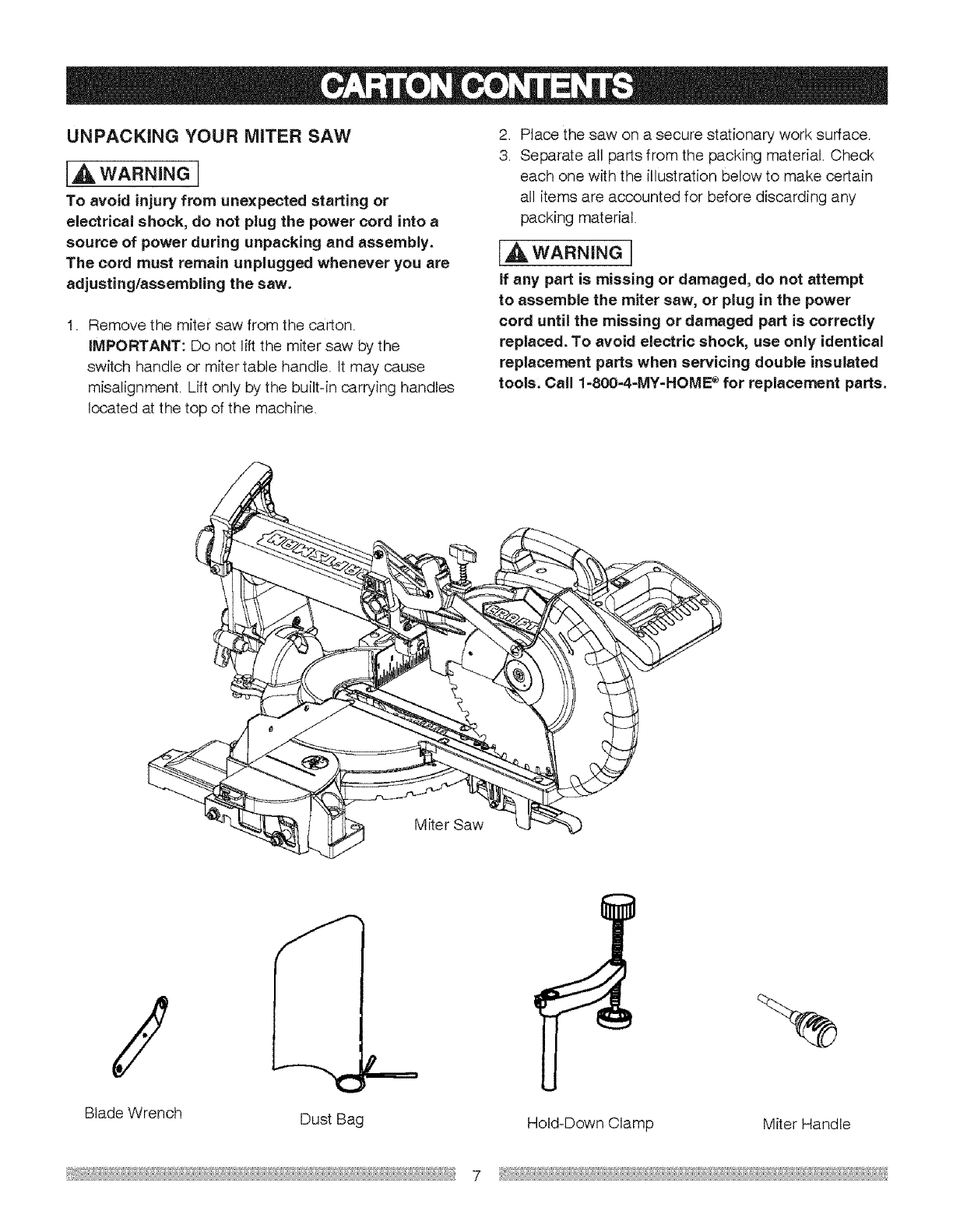
UNPACKING YOUR MITER SAW
[A WARNING[
To avoid injury from unexpected starting or
electrical shock, do not plug the power cord into a
source of power during unpacking and assembly.
The cord must remain unplugged whenever you are
adjusting/assembling the saw.
I. Remove the miter saw from the carton.
IMPORTANT: Do not lift the miter saw by the
switch handle or miter table handle. It may cause
misalignment. Lift only by the built-in carrying handles
located at the top of the machine.
,
3.
Place the saw on a secure stationary work surface.
Separate all parts from the packing material. Check
each one with the illustration below to make certain
all items are accounted for before discarding any
packing material.
IA WARNING[
If any part is missing or damaged, do not attempt
to assemble the miter saw, or plug in the power
cord until the missing or damaged part is correctly
replaced. To avoid electric shock, use only identical
replacement parts when servicing double insulated
tools. Call 1-800-4-MY-HOME e for replacement parts.
Miter Saw
Blade Wrench Dust Bag Hold-Down Clamp Miter Handle
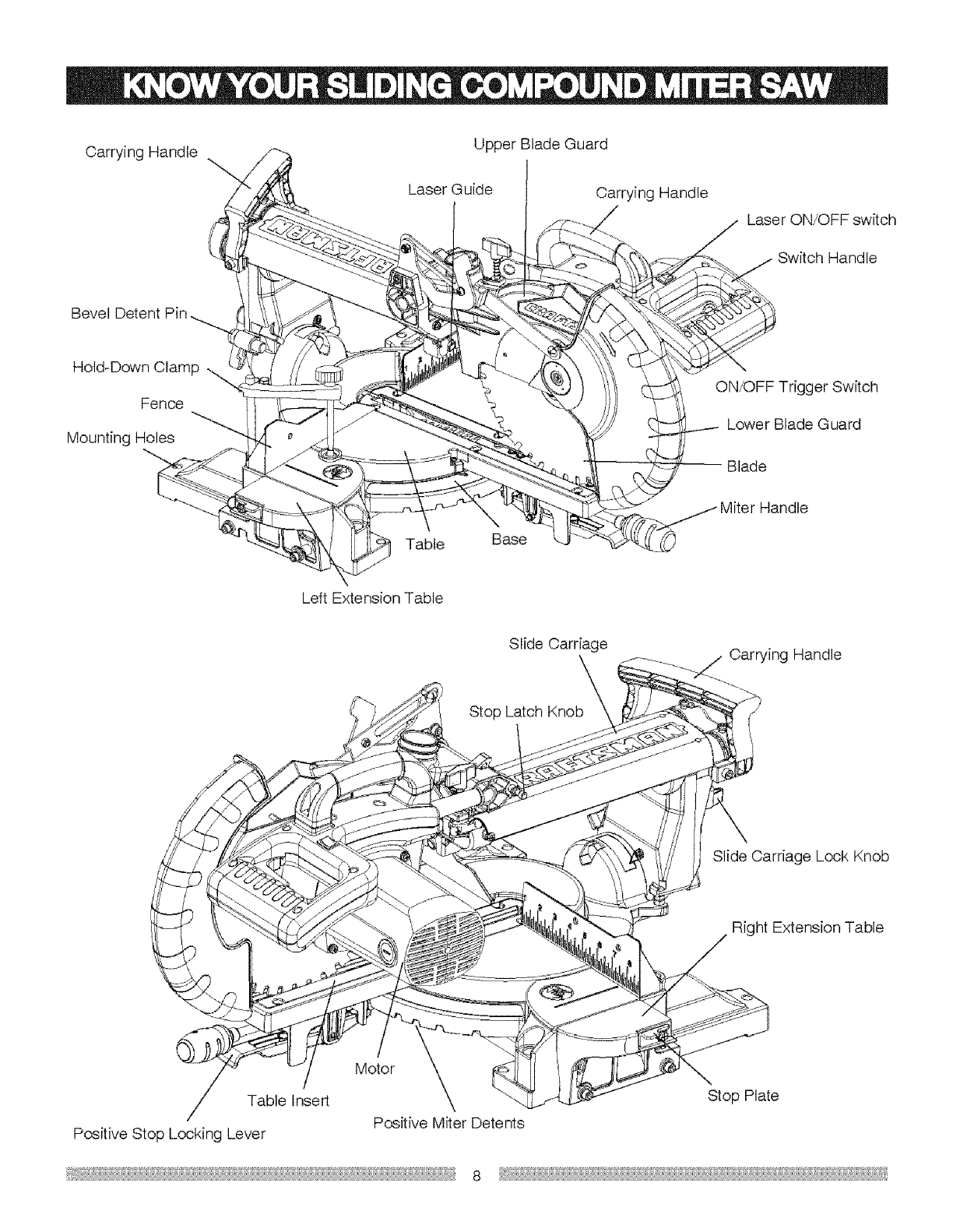
CarryingHandle UpperBladeGuard
LaserGuide CarryingHandle
LaserON/OFFswitch
SwitchHandle
BevelDetentPin
Hold-DownClamp,..,,
Fence
MountingHoles
ON/OFFTriggerSwitch
LowerBladeGuard
Blade
Table Base
LeftExtensionTable
SlideCarriage CarryingHandle
SlideCarriageLockKnob
RightExtensionTable
Motor
TableInsert
PositiveStopLockingLever PositiveMiterDetents
StopPlate
8
ARBOR LOCK - Allows the user to keep the blade from
rotating while tightening or loosening the arbor locking
bolt during blade replacement or removal.
BASE - Supports the table, holds accessories and
allows for workbench or leg set mounting.
WRENCH STORAGE - Convenient storage to prevent
misplacing the blade wrench.
WOODWORKING TERMS
ARBOR - The shaft on which a blade is mounted.
BEVEL LOCKING HANDLE - Locks the miter saw at a
desired bevel angle. BEVEL CUT -An angle cut made through the face of
the workpiece.
BEVEL SCALE -To measure the bevel angle of the
saw blade 0° to 45° left.
COVER PLATE SCREW - Loosen this screw and rotate
the plate for access to the blade arbor locking bolt.
FENCE - Helps to keep the workpiece from moving
when sawing. Scaled to assist with accurate cutting.
COMPOUND CUT - A simultaneous bevel and miter cut.
CROSSCUT -A cut made across the width or grain of
the workpiece.
FREEHAND- Performing a out without using a fence
(guide), hold down or other proper device to prevent the
workpiece from twisting during the cutting operation.
LOWER BLADE GUARD - Helps protect your hands
from the blade in the raised position. It retracts as the
blade is lowered
GUM -A sticky sap from wood products.
HEEL -Misalignment of the blade.
MITER HANDLE - Used to rotate the saw to the right or
left cutting position.
MITER SCALE - To measure the miter angle 0° to 45°
left, 0° to 45° right.
MOUNTING HOLES - Used to mount the miter saw to a
stable surface=
ON/OFF TRIGGER SWITCH -To start the tool, squeeze
the trigger. Release the trigger to stop the miter saw.
POSITIVE STOP LOCKING LEVER - Used in
combination with the miter handle, it Pocksthe miter saw
at a preset positive stop for the desired miter angle.
STOP LATCH - Locks the miter saw in the lowered
position for compact storage and transportation.
SWITCH HANDLE - The switch handle contains the
trigger switch. The blade is lowered into the workpiece
by pushing down on the handle. The saw will return to
its upright position when the handle is released.
KERF -The amount of material removed by blade cut.
MITER CUT -An angle cut made across the width or
grain of the workpiece.
RESIN - A sticky sap that has hardened.
REVOLUTIONS PER MINUTE (RPM) - The number of
turns completed by a spinning object in one minute.
SAW BLADE PATH - The area of the workpiece or
table top directly in line with the travel of the blade or the
part of the workpiece that will be cut.
SET - The distance between two saw blade tips, bent
outward in opposite directions to each other. The farther
apart the tips are, the greater the set.
WORKPIECE - The item being cut. The surfaces of a
workpiece are commonly referred to as faces, ends and
edges.
WARNING LABELS - Read and understand for your
own safety. Always make certain these are in place and
legible.
9
Estimated Assembly Time: 5 - 10 minutes
[,AWAR"I"GI
To avoid injury, do not connect this miter saw to the
power source until it is completely assembled and
adjusted and you have read and understood this
Operator's Manual.
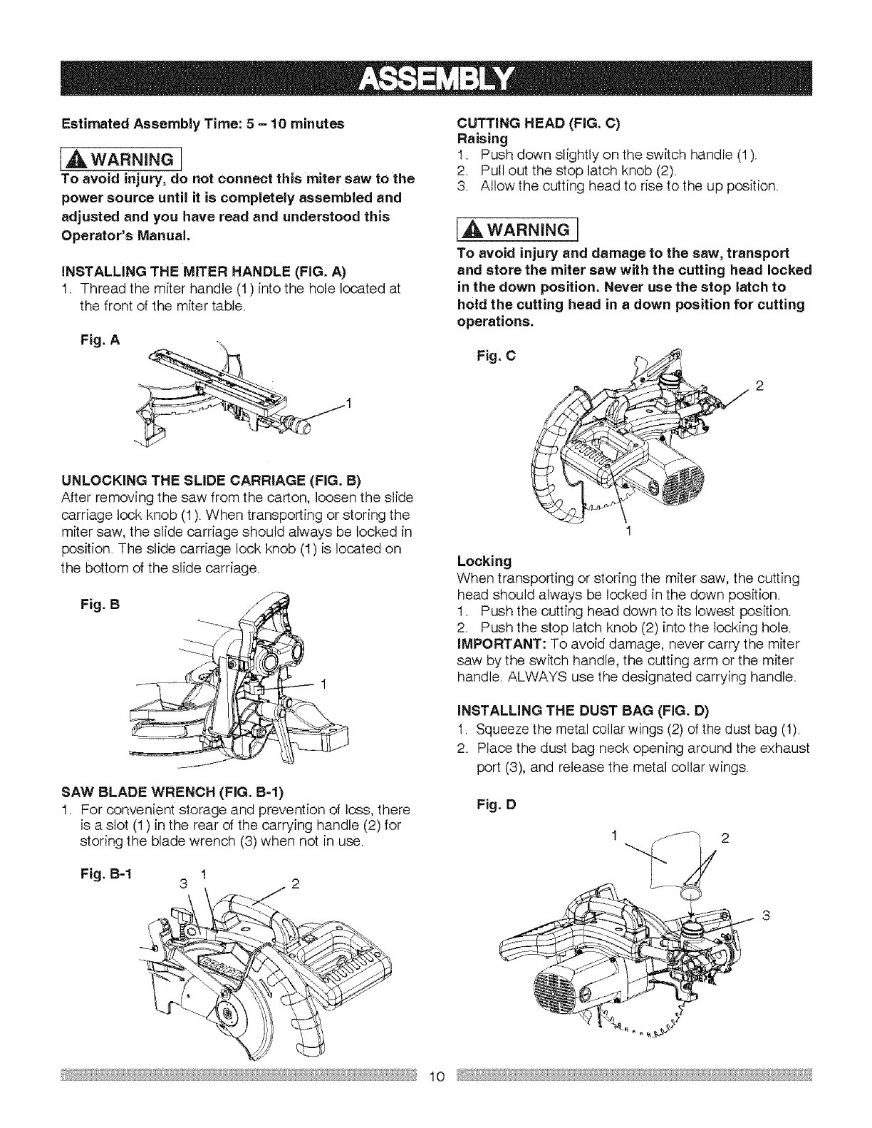
iNSTALLiNG THE MITER HANDLE (FIG. A)
1Thread the miter handle (1) into the hole located at
the front of the miter table.
Fig. A
UNLOCKING THE SLIDE CARRIAGE (FIG. B)
After removing the saw from the carton, loosen the slide
carriage lock knob (1). When transporting or storing the
miter saw, the slide carriage should always be locked in
position. The slide carriage lock knob (1) is located on
the bottom of the slide carriage.
Fig. B
SAW BLADE WRENCH (FIG. B-l)
1. For convenient storage and prevention of loss, there
is a slot (1) in the rear of the carrying handle (2) for
storing the blade wrench (3) when not in use.
Fig. B-1 I
3 2
CUTTING HEAD (FIG. C)
Raising
1. Push down slightly on the switch handle (I).
2. Pull out the stop latch knob (2).
3. Allow the cutting head to rise to the up position.
IA WARNINGI
To avoid injury and damage to the saw, transport
and store the miter saw with the cutting head locked
in the down position. Never use the stop latch to
hold the cutting head in adown position for cutting
operations.
Fig, C
Locking
When transporting or storing the miter saw, the cutting
head should always be locked in the down position.
1. Push the cutting head down to its lowest position.
2. Push the stop latch knob (2) into the locking hole.
IMPORTANT: To avoid damage, never carry the miter
saw by the switch handle, the cutting arm or the miter
handle. ALWAYS use the designated carrying handle.
iNSTALLiNG THE DUST BAG (FIG. D)
1. Squeeze the metal collar wings (2) of the dust bag (1).
2. Place the dust bag neck opening around the exhaust
port (3), and release the metal collar wings.
Fig. D
I 2
10
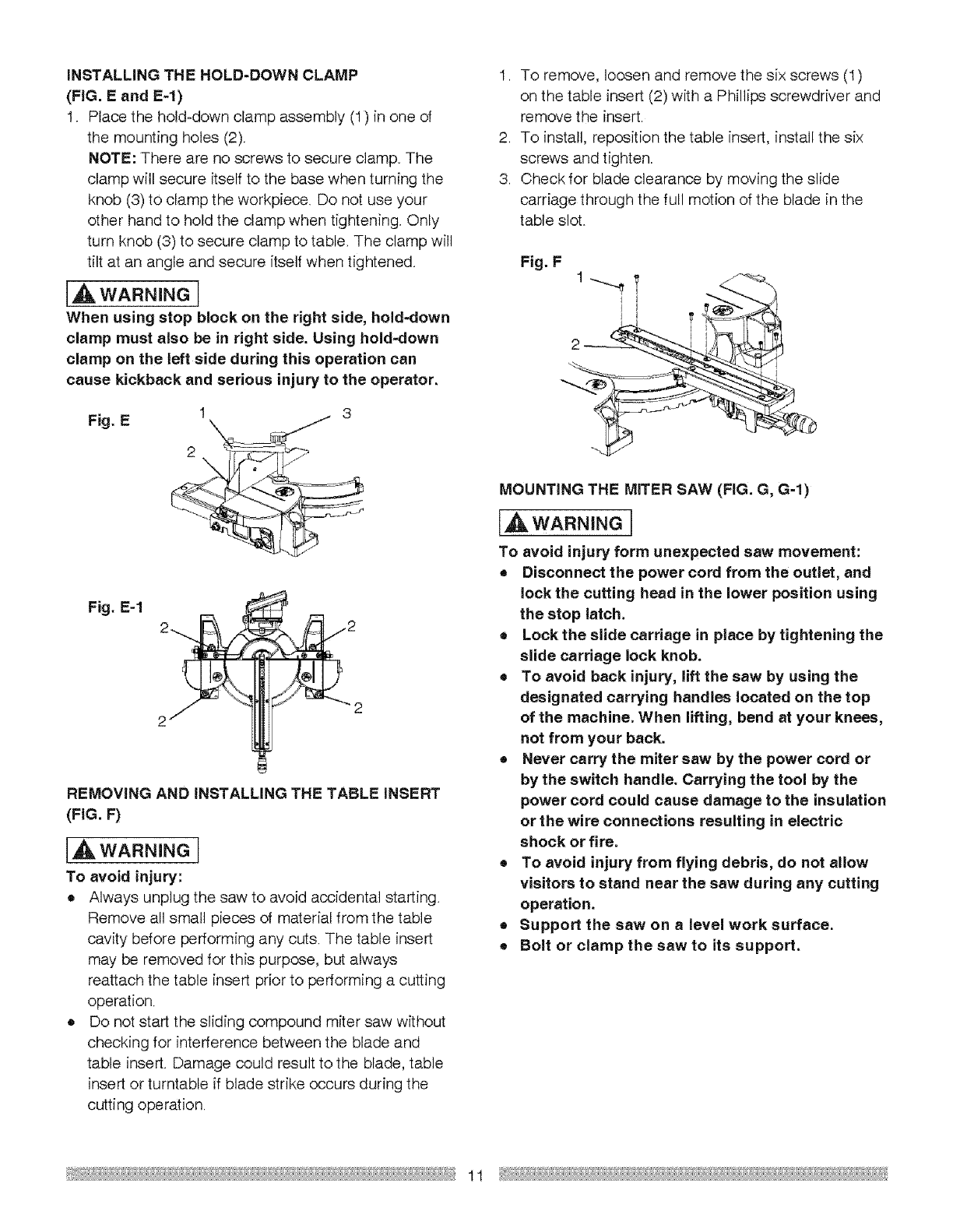
iNSTALLiNG THE HOLD-DOWN CLAMP
(FIG. E and E-l)
I. Place the hold=down clamp assembly (1) in one of
the mounting holes (2).
NOTE: There are no screws to secure clamp. The
clamp will secure itself to the base when turning the
knob (3) to clamp the workpiece. Do not use your
other hand to hold the clamp when tightening. Only
turn knob (3) to secure clamp to table. The clamp will
tilt at an angle and secure itself when tightened_
[A WARNINGI
When using stop block on the right side, hold-down
clamp must also be in right side. Using hold-down
clamp on the Deftside during this operation can
cause kickback and serious injury to the operator.
Fig. E!
Fig. E-1 2 J_ \_._/2
2
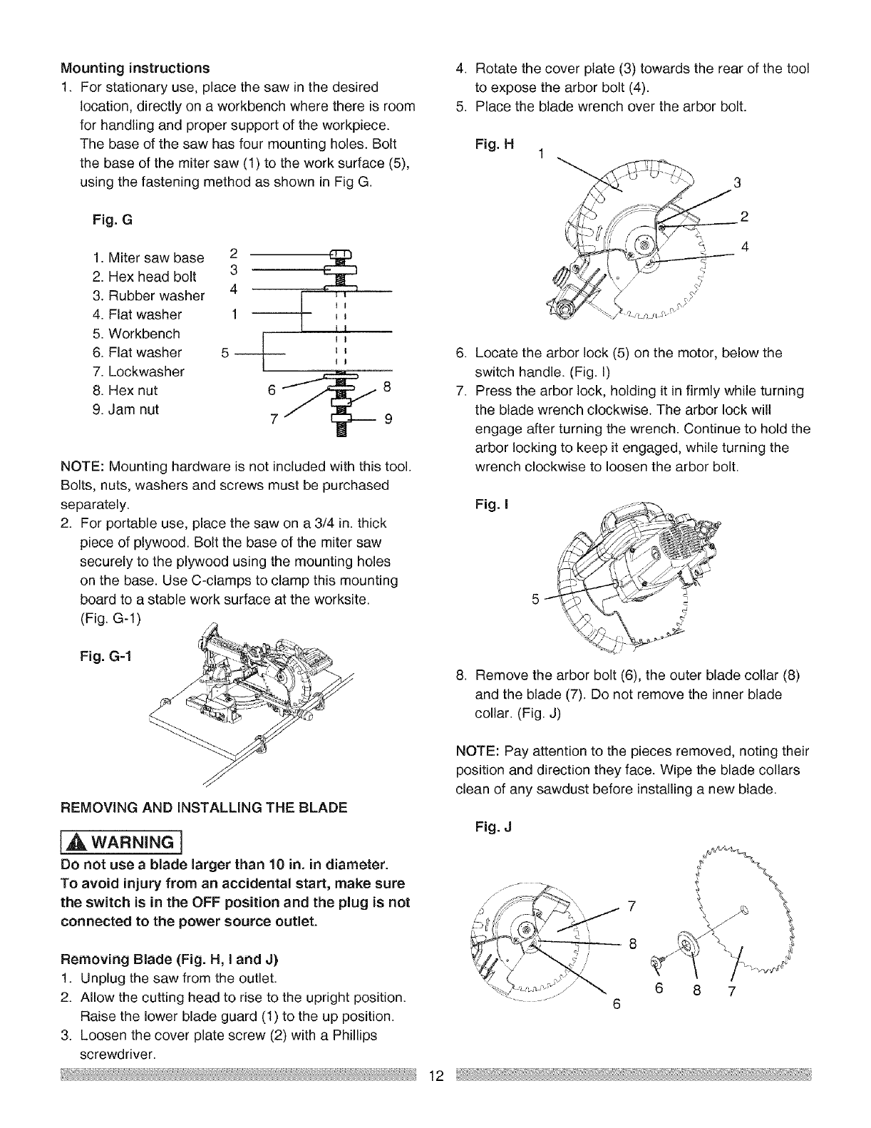
REMOVING AND iNSTALLiNG THE TABLE INSERT
(FIG. F)
[A wARNINe!
To avoid injury:
,= Always unplug the saw to avoid accidental starting.
Remove all small pieces of material from the table
cavity before performing any cuts. The table insert
may be removed for this purpose, but always
reattach the table insert prior to performing a cutting
operation.
• Do not start the sliding compound miter saw without
checking for interference between the blade and
table insert. Damage could result to the blade, table
insert or turntable if blade strike occurs during the
cutting operation.
1. To remove, loosen and remove the six screws (1)
on the table insert (2) with a Phillips screwdriver and
remove the insert.
2. To install, reposition the table insert, install the six
screws and tighten.
3. Check for blade clearance by moving the slide
carriage through the full motion of the blade in the
table slot.
Fig. F
I I
i i i
MOUNTING THE MITER SAW (FIG. G, G=I)
IAWARNmNGI
To avoid injury form unexpected saw movement:
=Disconnect the power cord from the outlet, and
lock the cutting head in the lower position using
the stop latch.
eLock the slide carriage in place by tightening the
slide carriage lock knob.
=To avoid back injury, lift the saw by using the
designated carrying handles located on the top
of the machine. When lifting, bend at your knees,
not from your back.
•Never carry the miter saw by the power cord or
by the switch handle. Carrying the tool by the
power cord could cause damage to the insulation
or the wire connections resulting in electric
shock or fire.
=To avoid injury from flying debris, do not allow
visitors to stand near the saw during any cutting
operation.
=Support the saw on a level work surface.
=Bolt or clamp the saw to its support.
11
Mountinginstructions
1. For stationary use, place the saw in the desired
location, directly on a workbench where there is room
for handling and proper support of the workpiece.
The base of the saw has four mounting holes. Bolt
the base of the miter saw (1) to the work surface (5),
using the fastening method as shown in Fig G.
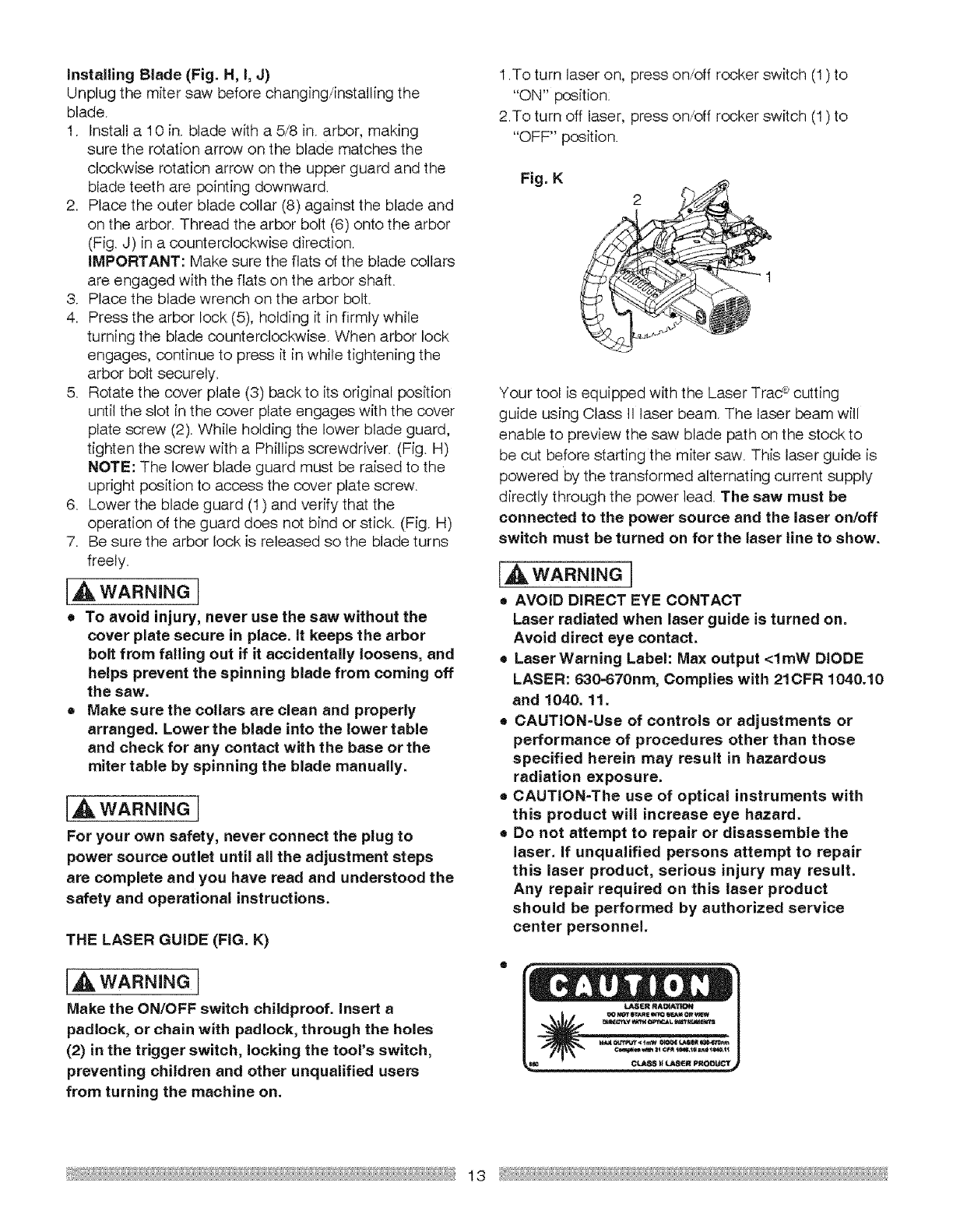
Fig. G
1. Miter saw base 2
2. Hex head bolt 3
3. Rubber washer 4 ,,
4. Flat washer 1 _
5. Workbench _I
I 1
6. Flat washer 5 _
7. Lockwasher
8. Hex nut _
9. Jam nut
8
9
NOTE: Mounting hardware is not included with this tool.
Bolts, nuts, washers and screws must be purchased
separately.
2. For portable use, place the saw on a 3/4 in. thick
piece of plywood. Bolt the base of the miter saw
securely to the plywood using the mounting holes
on the base. Use C-clamps to clamp this mounting
board to a stable work surface at the worksite.
(Fig. G-1 )
4. Rotate the cover plate (3) towards the rear of the tool
to expose the arbor bolt (4).
5. Place the blade wrench over the arbor bolt.
.
7.
Fig.H
//
3
2
4
Locate the arbor lock (5) on the motor, below the
switch handle. (Fig. I)
Press the arbor lock, holding it in firmly while turning
the blade wrench clockwise. The arbor lock will
engage after turning the wrench. Continue to hold the
arbor locking to keep it engaged, while turning the
wrench clockwise to loosen the arbor bolt.
Fig.I
5
Fig.G-1
REMOVING AND INSTALLING THE BLADE
WARNING]
Do not use a blade larger than 10 in. in diameter.
To avoid injury from an accidental start, make sure
the switch is in the OFF position and the plug is not
connected to the power source outmet.
Removing Blade (Fig. H, I and J)
1. Unplug the saw from the outlet.
2. Allow the cutting head to rise to the upright position.
Raise the lower blade guard (1) to the up position.
3. Loosen the cover plate screw (2) with a Phillips
screwdriver.
8. Remove the arbor bolt (6), the outer blade collar (8)
and the blade (7). Do not remove the inner blade
coltar. (Fig. J)
NOTE: Pay attention to the pieces removed, noting their
position and direction they face. Wipe the blade collars
clean of any sawdust before installing a new blade.
Fig. J
8 7
12
Installing Blade (Fig. H, I, J)
Unplug the miter saw before changing/installing the
blade.
I. Install a I 0 in. blade with a 5/8 in. arbor, making
sure the rotation arrow on the blade matches the
clockwise rotation arrow on the upper guard and the
blade teeth are pointing downward.
2. Place the outer blade collar (8) against the blade and
on the arbor. Thread the arbor bolt (6) onto the arbor
(Fig. J) in a counterclockwise direction.
IMPORTANT: Make sure the flats of the blade collars
are engaged with the flats on the arbor shaft.
3. Place the blade wrench on the arbor bolt.
4. Press the arbor lock (5), holding it in firmly while
turning the blade counterclockwise. When arbor lock
engages, continue to press it in while tightening the
arbor bolt securely.
5. Rotate the cover plate (3) back to its original position
until the slot in the cover plate engages with the cover
plate screw (2). While holding the lower blade guard,
tighten the screw with a Phillips screwdriver. (Fig. H)
NOTE: The lower blade guard must be raised to the
upright position to access the cover plate screw.
6. Lower the blade guard (1) and verify that the
operation of the guard does not bind or stick. (Fig. H)
7. Be sure the arbor lock is released so the blade turns
freely.
[A wARN.'JGI
•To avoid injury, never use the saw without the
cover plate secure in place. It keeps the arbor
bolt from falling out if it accidentally loosens, and
helps prevent the spinning blade from coming off
the saw.
• Make sure the collars are clean and properly
arranged. Lower the blade into the lower table
and check for any contact with the base or the
miter table by spinning the blade manually.
[A WAR.INGI
For your own safety, never connect the plug to
power source outlet until all the adjustment steps
are complete and you have read and understood the
safety and operational instructions.
THE LASER GUIDE (FIG. K)
[A WARNINGI
Make the ON/OFF switch childproof. Insert a
padlock, or chain with padlock, through the holes
(2) in the trigger switch, locking the tool's switch,
preventing children and other unqualified users
from turning the machine on.
1.To turn laser on, press on/off rocker switch (1) to
"ON" position:
2.To turn off laser, press on/off rocker switch (1) to
"OFF" position.
Fig. K
Your tool is equipped with the Laser Trad _ cutting
guide using Class II laser beam. The laser beam will
enable to preview the saw blade path on the stock to
be cut before starting the miter saw. This laser guide is
powered by the transformed alternating current supply
directly through the power lead. The saw must be
connected to the power source and the laser on/off
switch must be turned on for the laser line to show.
[A WARNING]
• AVOID DIRECT EYE CONTACT
Laser radiated when laser guide is turned on.
Avoid direct eye contact.
•Laser Warning Label: Max output <lmW DIODE
LASER: 630-670nm, Complies with 21CFR 1040.10
and 1040. 11.
• CAUTION-Use of controls or adjustments or
performance of procedures other than those
specified herein may result in hazardous
radiation exposure.
®CAUTiON-The use of optical instruments with
this product will increase eye hazard.
=Do not attempt to repair or disassemble the
laser. If unqualified persons attempt to repair
this laser product, serious injury may result.
Any repair required on this laser product
should be performed by authorized service
center personnel.
13
BEVEL STOP ADJUSTMENT
[4 WARNNNGI
To avoid injury from an accidental start, make sure
the switch is in the OFF position and the plug is not
connected to the power source outlet.
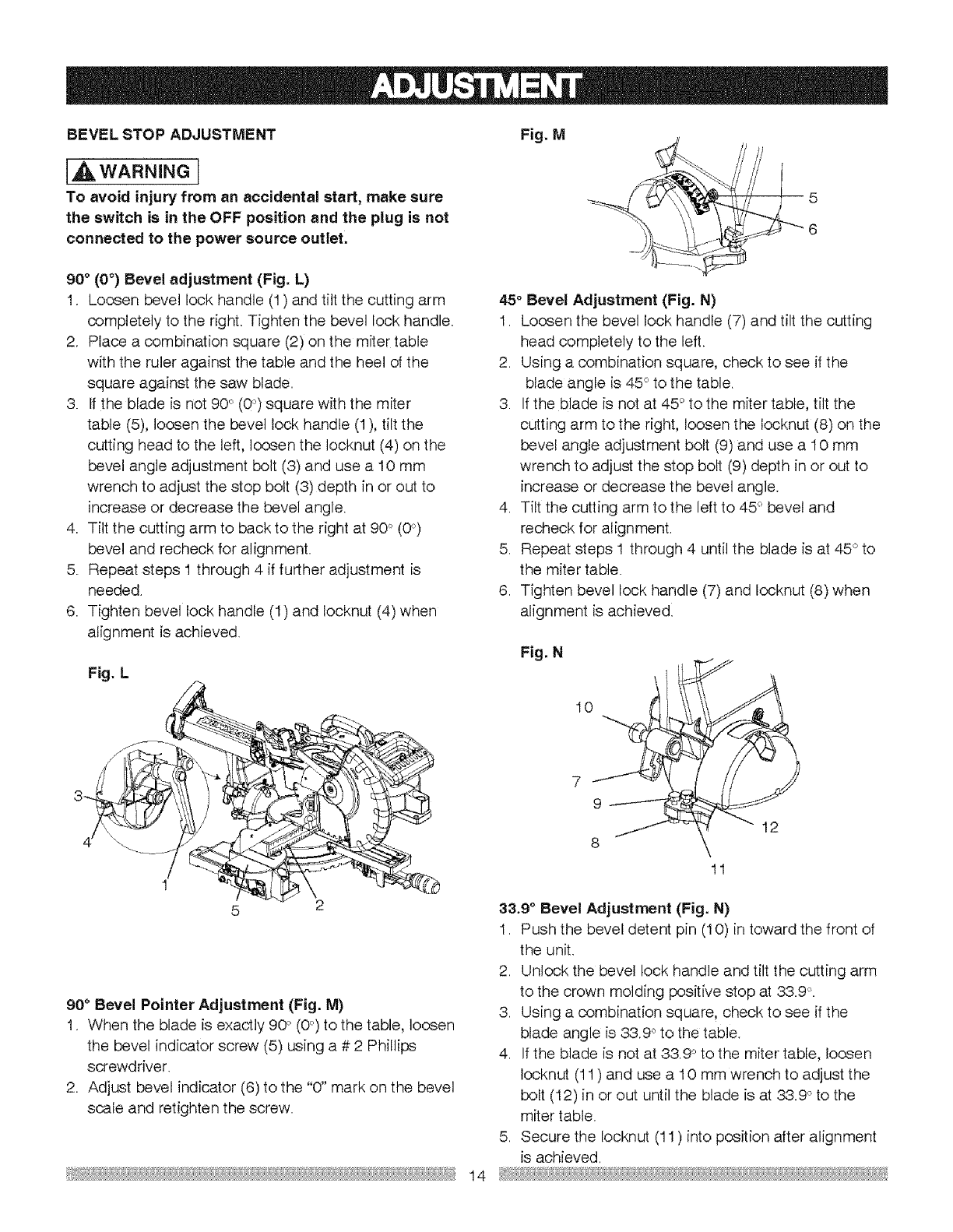
90 ° (0°) Bevel adjustment (Fig. L)
I. Loosen bevel lock handle (1) and tilt the cutting arm
completely to the right. Tighten the bevel lock handle.
2. Place a combination square (2) on the miter table
with the ruler against the table and the heel of the
square against the saw blade.
3. If the blade is not 90°(0°) square with the miter
table (5), loosen the bevel lock handle (I), tilt the
cutting head to the left, loosen the Iocknut (4) on the
bevel angle adjustment bolt (3) and use a 10 mm
wrench to adjust the stop bolt (3) depth in or out to
increase or decrease the bevel angle.
4 Tilt the cutting arm to back to the right at 90 _'(0°)
bevel and recheck for alignment.
5. Repeat steps 1 through 4 if further adjustment is
needed.
6 Tighten bevel lock handle (1) and Iocknut (4) when
alignment is achieved.
Fig. L
1
5 2
90 ° Bevel Pointer Adjustment (Fig. M)
1. When the blade is exactly 90 °`(0°) to the table, loosen
the bevel indicator screw (5) using a # 2 Phillips
screwdriver.
2. Adjust bevel indicator (6) to the "0" mark on the bevel
scale and retighten the screw.
Fig. My
5
6
45°Bevel Adjustment (Fig. N)
1. Loosen the bevel lock handle (7) and tilt the cutting
head completely to the left.
2. Using a combination square, check to see if the
blade angle is 45 ° to the table.
3. If the blade is not at 45 ° to the miter table, tilt the
cutting arm to the right, loosen the Iocknut (8) on the
bevel angle adjustment bolt (9) and use a 10 mm
wrench to adjust the stop bolt (9) depth in or out to
increase or decrease the bevel angle.
4. Tilt the cutting arm to the left to 45° bevel and
recheck for align ment.
5. Repeat steps 1 through 4 until the blade is at 45 ° to
the miter table.
6. Tighten bevel lock handle (7) and Iocknut (8) when
alignment is achieved
Fig. N 10 i
7
9_---- i
J
8
11
12
33.9 °Bevel Adjustment (Fig. N)
1. Push the bevel detent pin (10) in toward the front of
the unit.
2. Unlock the bevel lock handle and tilt the cutting arm
to the crown molding positive stop at 33.9 °
3. Using a combination square, check to see if the
blade angle is 33.90 to the table.
4. If the blade is not at 33.90 to the miter table, loosen
Iocknut (11 ) and use a 10 mm wrench to adjust the
bolt (12) in or out until the blade is at 33.9 ° to the
miter table.
5. Secure the Iocknut (11) into position after alignment
is achieved.
14
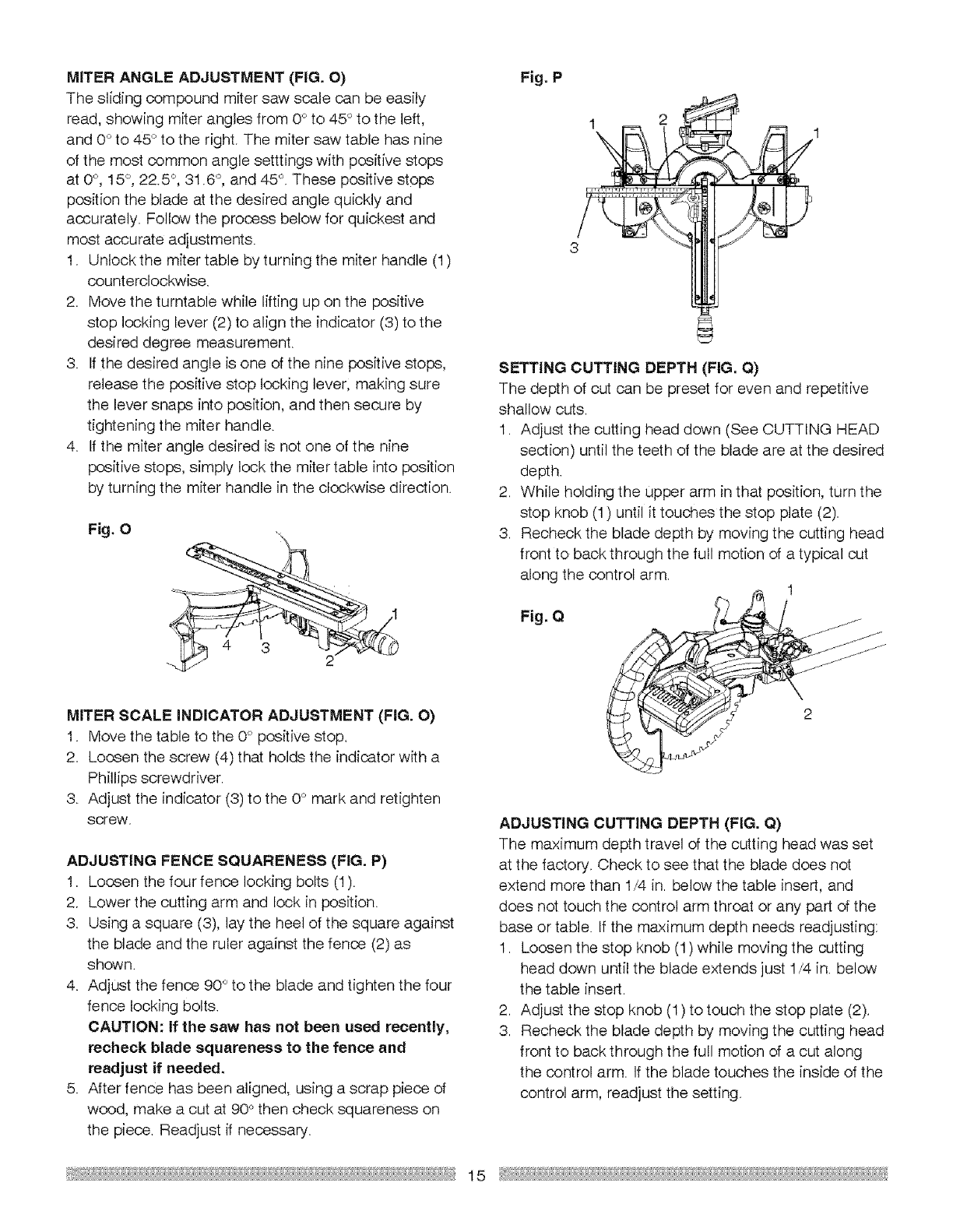
MITER ANGLE ADJUSTMENT (FIG. O)
The sliding compound miter saw scale can be easily
read, showing miter angles from 0° to 45°to the left,
and 0_'to 45 ° to the right. The miter saw table has nine
of the most common angle setttings with positive stops
at 0_',15°, 22.5 °, 31.6 °, and 45°. These positive stops
position the blade at the desired angle quickly and
accurately. Follow the process below for quickest and
most accurate adjustments.
I. Unlock the miter table by turning the miter handle (1)
counterclockwise.
2. Move the turntable while lifting up on the positive
stop locking lever (2) to align the indicator (3) to the
desired degree measurement.
3. If the desired angle is one of the nine positive stops,
release the positive stop locking lever; making sure
the lever snaps into position, and then secure by
tightening the miter handle.
4. If the miter angle desired is not one of the nine
positive stops, simply lock the miter table into position
by turning the miter handle in the clockwise direction.
Fig. 0
MITER SCALE INDICATOR ADJUSTMENT (FIG. O)
I. Move the table to the 0° positive stop.
2. Loosen the screw (4) that holds the indicator with a
Phillips screwdriver.
3. Adjust the indicator (3) to the 0° mark and retighten
screw.
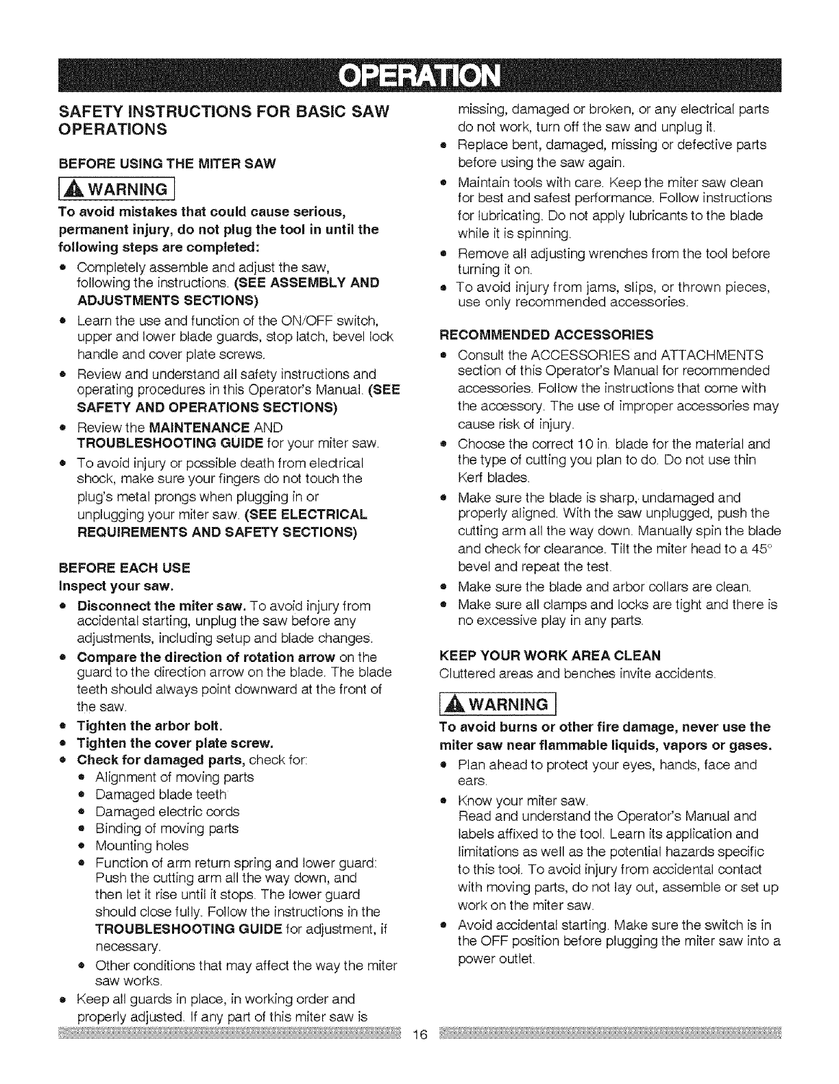
ADJUSTING FENCE SQUARENESS (FIG. P)
1. Loosen the four fence locking bolts (1).
2. Lower the cutting arm and lock in position.
3. Using a square (3), lay the heel of the square against
the blade and the ruler against the fence (2) as
shown.
4. Adjust the fence 90° to the blade and tighten the four
fence locking bolts.
CAUTION: If the saw has not been used recently,
recheck blade squareness to the fence and
readjust if needed.
5. After fence has been aligned, using a scrap piece of
wood, make a cut at 90° then check squareness on
the piece. Readjust if necessary.
Fig. P
1
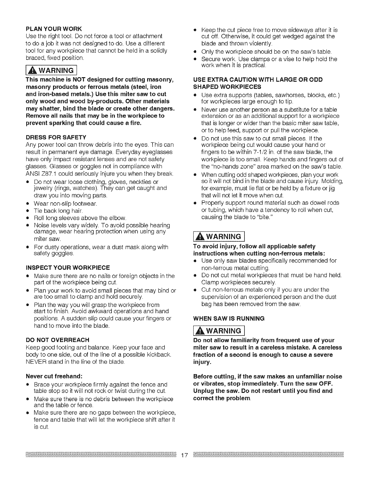
SETTING CUTTING DEPTH (FIG. Q)
The depth of cut can be preset for even and repetitive
shallow cuts.
1. Adjust the cutting head down (See CUTTING HEAD
section) until the teeth of the blade are at the desired
depth.
2. While holding the upper arm in that position, turn the
stop knob (1) until it touches the stop plate (2).
3. Recheck the blade depth by moving the cutting head
front to back through the full motion of a typical cut
along the control arm. 1
Fig. Q
2
ADJUSTING CUTTING DEPTH (FIG. Q)
The maximum depth travel of the cutting head was set
at the factory. Check to see that the blade does not
extend more than 1/4 in. below the table insert, and
does not touch the control arm throat or any part of the
base or table. If the maximum depth needs readjusting:
I. Loosen the stop knob (1) while moving the cutting
head down until the blade extends just 1/4 in. below
the table insert.
2. Adjust the stop knob (1) to touch the stop plate (2).
3. Recheck the blade depth by moving the cutting head
front to back through the full motion of a cut along
the control arm. If the blade touches the inside of the
control arm, readjust the setting.
15
SAFETY iNSTRUCTiONS FOR BASIC SAW
OPERATIONS
BEFORE USING THE MITER SAW
[A WARNING
To avoid mistakes that could cause serious,
permanent injury, do not plug the tool in until the
following steps are completed:
•Completely assemble and adjust the saw,
following the instructions. (SEE ASSEMBLY AND
ADJUSTMENTS SECTIONS)
o Learn the use and function of the ON/OFF switch,
upper and lower blade guards, stop latch, bevel lock
handle and cover plate screws.
• Review and understand all safety instructions and
operating procedures in this Operator's Manual. (SEE
SAFETY AND OPERATIONS SECTIONS)
• Reviewthe MAINTENANCE AND
TROUBLESHOOTING GUIDE for your miter saw.
• To avoid injury or possible death from electrical
shock, make sure your fingers do not touch the
plug's metal prongs when plugging in or
unplugging your miter saw. (SEE ELECTRICAL
REQUIREMENTS AND SAFETY SECTIONS)
BEFORE EACH USE
Inspect your saw.
•Disconnect the miter saw. To avoid injury from
accidental starting, unplug the saw before any
adjustments, including setup and blade changes.
•Compare the direction of rotation arrow on the
guard to the direction arrow on the blade. The blade
teeth should always point downward at the front of
the saw.
•Tighten the arbor bolt.
•Tighten the cover plate screw.
•Check for damaged parts, check for:
o Alignment of moving parts
e Damaged blade teeth
• Damaged electric cords
o Binding of moving parts
e Mounting holes
• Function of arm return spring and lower guard:
Push the cutting arm all the way down, and
then let it rise until it stops. The lower guard
should close fully. Follow the instructions in the
TROUBLESHOOTING GUIDE for adjustment, if
necessary.
=, Other conditions that may affect the way the miter
saw works.
• Keep all guards in place, in working order and
properly adjusted. If any part of this miter saw is
missing, damaged or broken, or any electrical parts
do not work, turn off the saw and unplug it.
• Replace bent, damaged, missing or defective parts
before using the saw again.
• Maintain tools with care. Keep the miter saw clean
for best and safest performance. Follow instructions
for lubricating. Do not apply lubricants to the blade
while it is spinning.
• Remove all adjusting wrenches from the tool before
turning it on.
To avoid injury from jams, slips, or thrown pieces,
use only recommended accessories.
RECOMMENDED ACCESSORIES
• Consult the ACCESSORIES and ATTACHMENTS
section of this Operator's Manual for recommended
accessories. Follow the instructions that come with
the accessory'. The use of improper accessories may
cause risk of injury.
• Choose the correct 10 in. blade for the material and
the type of cutting you plan to do. Do not use thin
Kerr blades.
• Make sure the blade is sharp, undamaged and
properly aligned. With the saw unplugged, push the
cutting arm all the way down. Manually spin the blade
and check for clearance. Tilt the miter head to a 45 °
bevel and repeat the test.
• Make sure the blade and arbor collars are clean.
•Make sure all clamps and locks are tight and there is
no excessive play in any parts.
KEEP YOUR WORK AREA CLEAN
Cluttered areas and benches invite accidents.
[,&WARNmNG]
To avoid burns or other fire damage, never use the
miter saw near flammable liquids, vapors or gases.
o Plan ahead to protect your eyes, hands, face and
ears.
• Know your miter saw.
Read and understand the Operator's Manual and
labels affixed to the tool. Learn its application and
limitations as well as the potential hazards specific
to this tool. To avoid injury from accidental contact
with moving parts, do not lay out, assemble or set up
work on the miter saw.
• Avoid accidental starting. Make sure the switch is in
the OFF position before plugging the miter saw into a
power outlet.
16
PLAN YOUR WORK
Use the right tool. Do not force a tool or attachment
to do a job it was not designed to do. Use a different
tool for any workpiece that cannot be held in a solidly
braced, fixed position.
[A WARNINGI
This machine is NOT designed for cutting masonry,
masonry products or ferrous metals (steel, iron
and iron-based metals.) Use this miter saw to cut
only wood and wood by-products. Other materials
may shatter, bind the blade or create other dangers.
Remove all nails that may be in the workpiece to
prevent sparking that could cause a fire.
DRESS FOR SAFETY
Any power tool can throw debris into the eyes. This can
result in permanent eye damage. Everyday eyeglasses
have only impact resistant lenses and are not safety
glasses. Glasses or goggles not in compliance with
ANSI Z87.! could seriously injure you when they break.
• Do not wear loose clothing, gloves, neckties or
jewelry (rings, watches). They can get caught and
draw you into moving parts.
o Wear non-slipfootwear.
• Tie back long hair.
• Roll long sleeves above the elbow.
• Noise levels vary widely. To avoid possible hearing
damage, wear hearing protection when using any
miter saw.
• For dusty operations, wear a dust mask along with
safety goggles.
iNSPECT YOUR WORKPIECE
• Make sure there are no nails or foreign objects in the
part of the workpiece being cut.
• Plan your work to avoid small pieces that may bind or
are too small to clamp and hold securely.
• Plan the way you will grasp the workpiece from
start to finish. Avoid awkward operations and hand
positions. A sudden slip could cause your fingers or
hand to move into the blade.
DO NOT OVERREACH
Keep good footing and balance. Keep your face and
body to one side, out of the line of a possible kickback.
NEVER stand in the line of the blade.
Never cut freehand:
• Brace your workpiece firmly against the fence and
table stop so it will not rock or twist during the cut.
• Make sure there is no debris between the workpiece
and the table or fence.
• Make sure there are no gaps between the workpiece,
fence and table that will let the workpiece shift after it
is cut.
• Keep the out piece free to move sideways after it is
cut off. Otherwise, it could get wedged against the
blade and thrown violently.
e Only the workpiece should be on the saw's table.
• Secure work. Use clamps or a vise to help hold the
work when it is practical.
USE EXTRA CAUTION WITH LARGE OR ODD
SHAPED WORKPIECES
• Use extra supports (tables, sawhorses, blocks, etc.)
for workpieces large enough to tip.
o Never use another person as a substitute for a table
extension or as an additional support for a workpiece
that is longer or wider than the basic miter saw table,
or to help feed, support or pull the workpiece.
o Do not use this saw to cut small pieces. If the
workpieoe being cut would cause your hand or
fingers to be within 7-1/2 in. of the saw blade, the
workpiece is too small. Keep hands and fingers out of
the "no-hands zone" area marked on the saw's table.
o When cutting odd shaped workpieces, plan your work
so it will not bind in the blade and cause injury. Molding,
for example, must lie flat or be held by a fixture or jig
that will not let it move when cut.
• Properly support round material such as dowel rods
or tubing, which have a tendency to roll when cut,
causing the blade to "bite."
[,&WARNING]
To avoid injury, follow all applicable safety
instructions when cutting non-ferrous metals:
• Use only saw blades specifically recommended for
non-ferrous metal cutting.
• Do not cut metal workpieces that must be hand held.
Clamp workpieces securely.
• Cut non-ferrous metals only if you are under the
supervision of an experienced person and the dust
bag has been removed from the saw.
WHEN SAW IS RUNNING
IA WARNINGI
Do not allow familiarity from frequent use of your
miter saw to result in a careless mistake. A careless
fraction of a second is enough to cause a severe
injury.
Before cutting, if the saw makes an unfamiliar noise
or vibrates, stop immediately. Turn the saw OFF.
Unplug the saw. Do not restart until you find and
correct the problem.
17
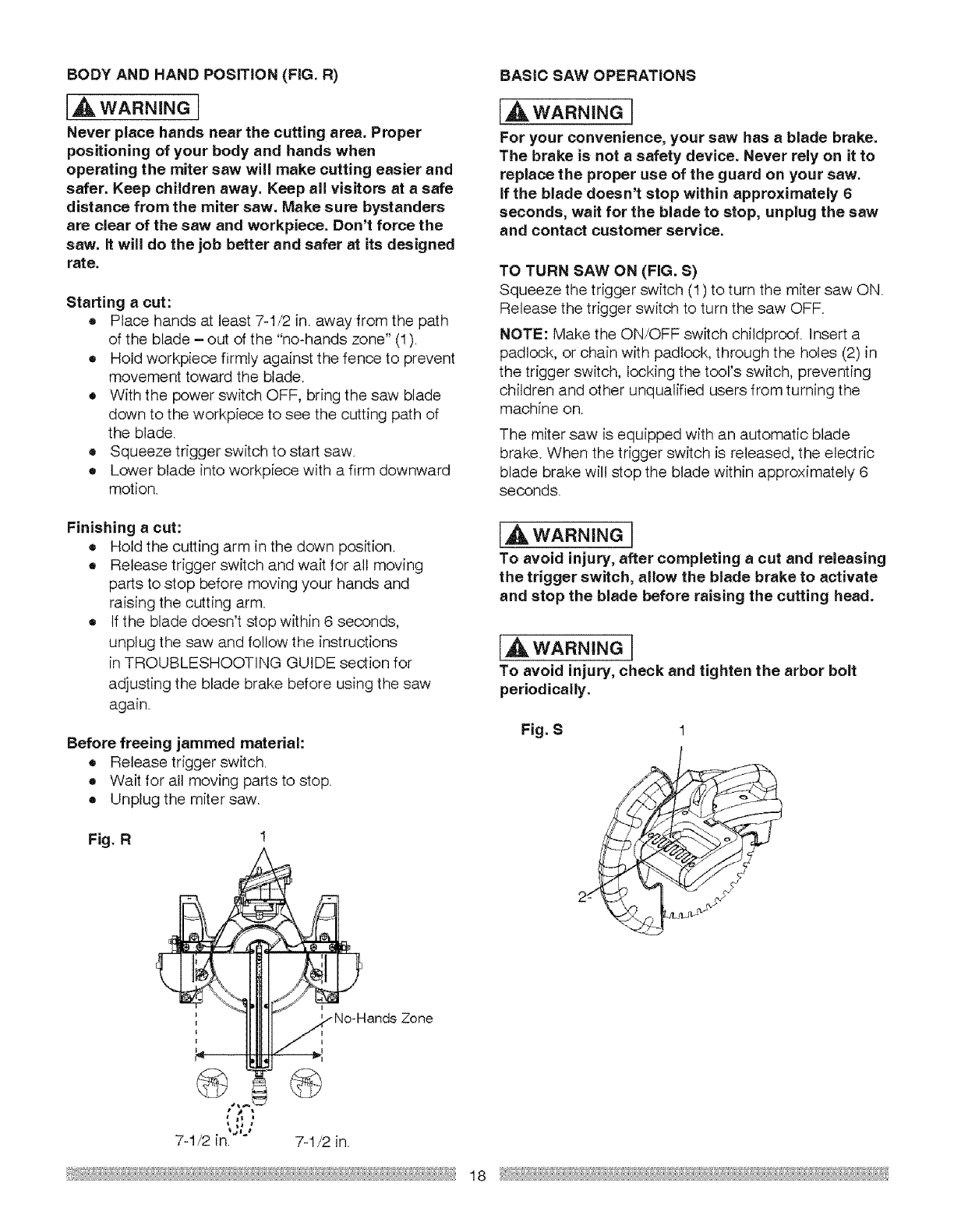
BODY AND HAND POSITION (FIG. R)
(AWARNINO[
Never place hands near the cutting area. Proper
positioning of your body and hands when
operating the miter saw will make cutting easier and
safer. Keep children away. Keep aH visitors at a safe
distance from the miter saw. Make sure bystanders
are clear of the saw and workpiece. Don't force the
saw. It will do the job better and safer at its designed
rate.
Starting a cut:
o Place hands at least 7=1/2 in. away from the path
of the blade - out of the "no-hands zone" (1).
• Hold workpiece firmly against the fence to prevent
movement toward the blade.
• With the power switch OFF, bring the saw blade
down to the workpiece to see the cutting path of
the blade.
= Squeeze trigger switch to start saw.
• Lower blade into workpiece with a firm downward
motion.
Finishing acut:
o Hold the cutting arm in the down position.
o Release trigger switch and wait for all moving
parts to stop before moving your hands and
raising the cutting arm
o If the blade doesn't stop within 6 seconds,
unplug the saw and follow the instructions
in TROUBLESHOOTING GUIDE section for
adjusting the blade brake before using the saw
again.
Before freeing jammed material:
6 Release trigger switch.
o Wait for all moving parts to stop.
• Unplug the miter saw.
Fig. R
BASIC SAW OPERATIONS
[AWARNINGJ
For your convenience, your saw has a blade brake.
The brake is not a safety device. Never rely on it to
replace the proper use of the guard on your saw.
If the blade doesn't stop within approximately 6
seconds, wait for the blade to stop, unplug the saw
and contact customer service.
TO TURN SAW ON (FIG. S)
Squeeze the trigger switch (I) to turn the miter saw ON.
Release the trigger switch to turn the saw OFF.
NOTE: Make the ON/OFF switch chiidproof. Insert a
padlock, or chain with padlock, through the holes (2) in
the trigger switch, locking the tool's switch, preventing
children and other unqualified users from turning the
machine on.
The miter saw is equipped with an automatic blade
brake. When the trigger switch is released, the electric
blade brake will stop the blade within approximately 6
seconds.
(A WARNING[
To avoid injury, after completing acut and releasing
the trigger switch, allow the blade brake to activate
and stop the blade before raising the cutting head.
IAWARNmNOI
To avoid injury, check and tighten the arbor bolt
periodically.
Fig. S I
• # l
7-I/2 in_'''° 7-1/2 in.
18
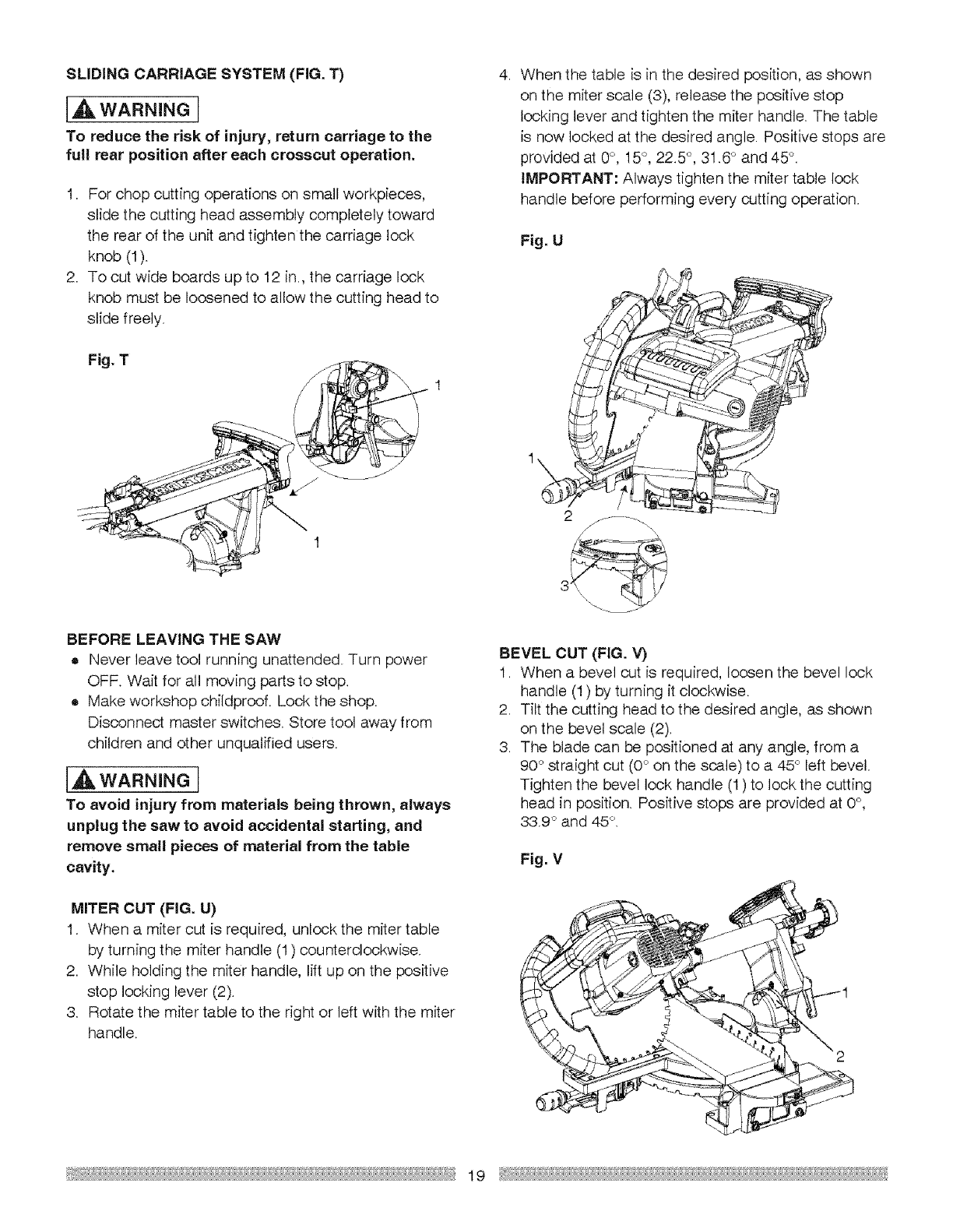
SLIDING CARRIAGE SYSTEM (FIG. 1")
[A WARNINGI
To reduce the risk of injury, return carriage to the
full rear position after each crosscut operation.
I. For chop cutting operations on small workpieces,
slide the cutting head assembly completely toward
the rear of the unit and tighten the carriage lock
knob (1).
2. To cut wide boards up to 12 in., the carriage lock
knob must be loosened to allow the cutting head to
slide freely.
Fig. T
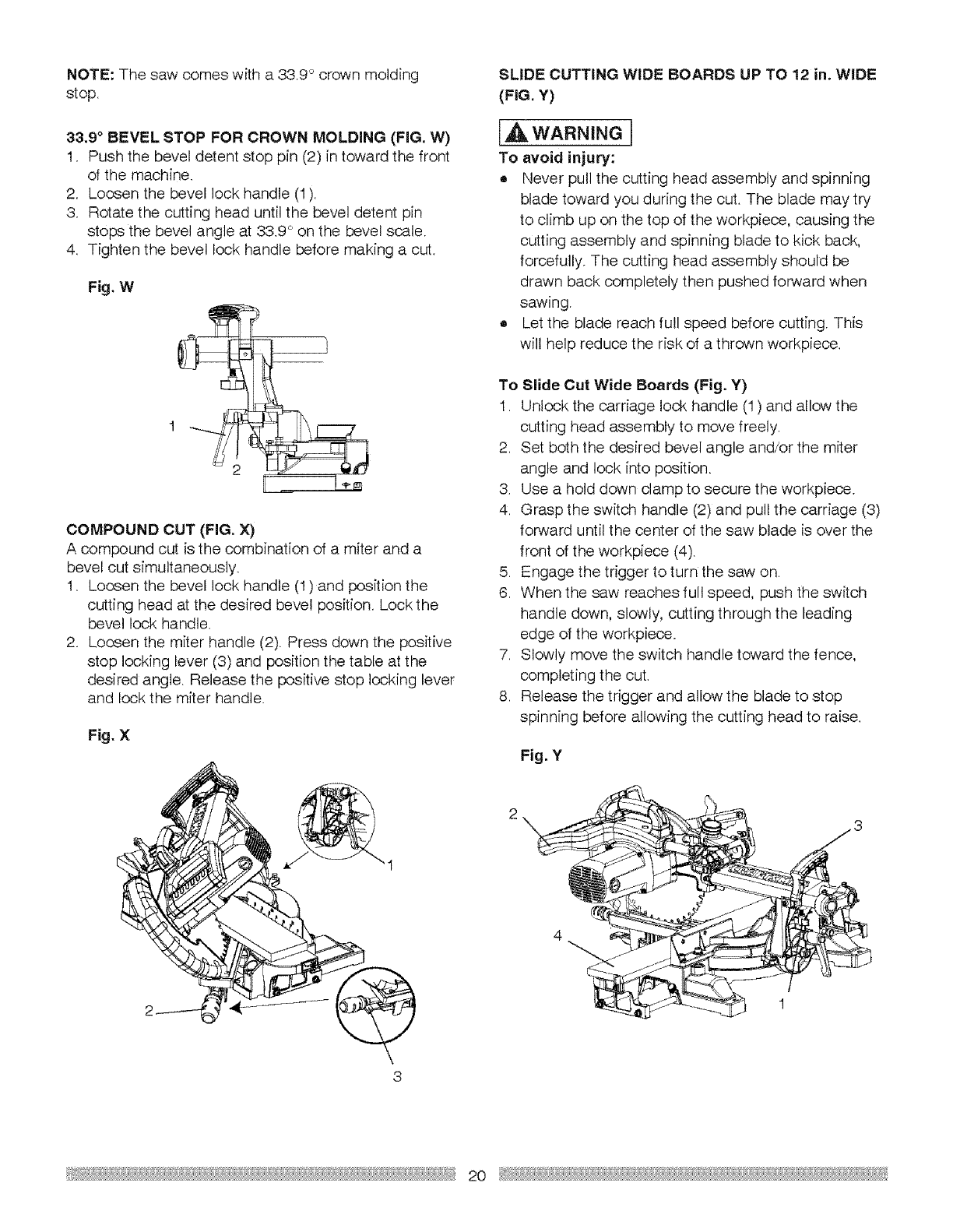
When the table is in the desired position, as shown
on the miter scale (3), release the positive stop
locking lever and tighten the miter handle. The table
is now locked at the desired angle. Positive stops are
provided at 0°, 15°, 225 °, 31.6° and 45°.
IMPORTANT: Always tighten the miter table lock
handle before performing every cutting operation.
Fig. U
BEFORE LEAVING THE SAW
,Never leave tool running unattended. Turn power
OFF. Wait for all moving parts to stop.
® Make workshop childproof. Lock the shop.
Disconnect master switches. Store tool away from
children and other unqualified users.
[A wAR.mr,JGI
To avoid injury from materials being thrown, always
unplug the saw to avoid accidental starting, and
remove small pieces of material from the table
cavity.
MITER CUT (FIG. U)
I. When a miter cut is required, unlock the miter table
by turning the miter handle (1) counterclockwise.
2. While holding the miter handle, lift up on the positive
stop locking lever (2).
3. Rotate the miter table to the right or left with the miter
handle.
BEVEL CUT (FIG. V)
1. When a bevel cut is required, loosen the bevel lock
handle (1) by turning it clockwise.
2. Tilt the cutting head to the desired angle, as shown
on the bevel scale (2).
3. The blade can be positioned at any angle, from a
90° straight cut (0° on the scale) to a 45 ° left bevel.
Tighten the bevel lock handle (1) to lock the cutting
head in position. Positive stops are provided at 0°,
33.9 ° and 45 °1
Fig. V
19
NOTE:Thesawcomeswitha33.9°crownmolding
stop.
33.9°BEVEL STOP FOR CROWN MOLDING (FIG. W)
I. Push the bevel detent stop pin (2) in toward the front
of the machine.
2. Loosen the bevel lock handle (1).
3. Rotate the cutting head until the bevel detent pin
stops the bevel angle at 33.9 c'on the bevel scale.
4. Tighten the bevel lock handle before making a cut.
Fig. W
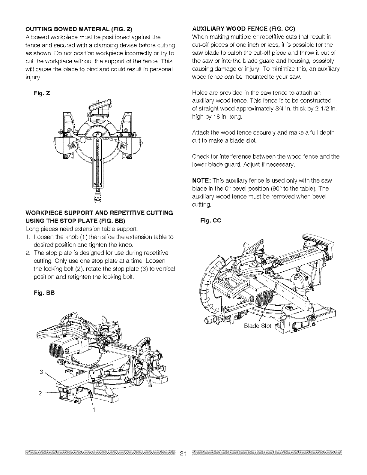
COMPOUND CUT (FIG. X)
A compound cut is the combination of a miter and a
bevel cut simultaneously,
I. Loosen the bevel lock handle (1) and position the
cutting head at the desired bevel position. Lock the
bevel lock handle.
2. Loosen the miter handle (2). Press down the positive
stop locking lever (3) and position the table at the
desired angle. Release the positive stop locking lever
and lock the miter handle.
Fig. X
SLIDE CUTTING WIDE BOARDS UP TO 12 in. WIDE
(FIG. Y)
IAWA"Ni"GI
To avoid injury:
• Never pull the cutting head assembly and spinning
blade toward you during the cut. The blade may try
to climb up on the top of the workpiece, causing the
cutting assembly and spinning blade to kick back,
forcefully. The cutting head assembly should be
drawn back completely then pushed forward when
sawing
• Let the blade reach full speed before cutting. This
will help reduce the risk of a thrown workpiece.
To Slide Cut Wide Boards (Fig. Y)
1. Unlock the carriage lock handle (I) and allow the
cutting head assembly to move freely.
2. Set both the desired bevel angle and/or the miter
angle and lock into position.
3. Use a hold down clamp to secure the workpiece.
4. Grasp the switch handle (2) and pull the carriage (3)
forward until the center of the saw blade is over the
front of the workpiece (4).
5. Engage the trigger to turn the saw on.
6. When the saw reaches full speed, push the switch
handle down, slowly, cutting through the leading
edge of the workpiece.
7. Slowly move the switch handle toward the fence,
completing the cut.
8. Release the trigger and allow the blade to stop
spinning before allowing the cutting head to raise.
Fig, Y
2O
CUTTING BOWED MATERIAL (FIG. Z)
A bowed workpiece must be positioned against the
fence and secured with a cramping devise before cutting
as shown. Do not position workpiece incorrectly or try to
cut the workpiece without the support of the fence. This
will cause the blade to bind and could result in personal
injury.
Fig. Z
WORKPIECE SUPPORT AND REPETiTiVE CUTTING
USING THE STOP PLATE (FIG, BB)
Long pieces need extension table support.
1. Loosen the knob (1) then slide the extension table to
desired position and tighten the knob.
2. The stop plate is designed for use during repetitive
cutting. Only use one stop plate at a time. Loosen
the locking bolt (2), rotate the stop plate (3) to vertical
position and retighten the locking bolt.
Fig. BB
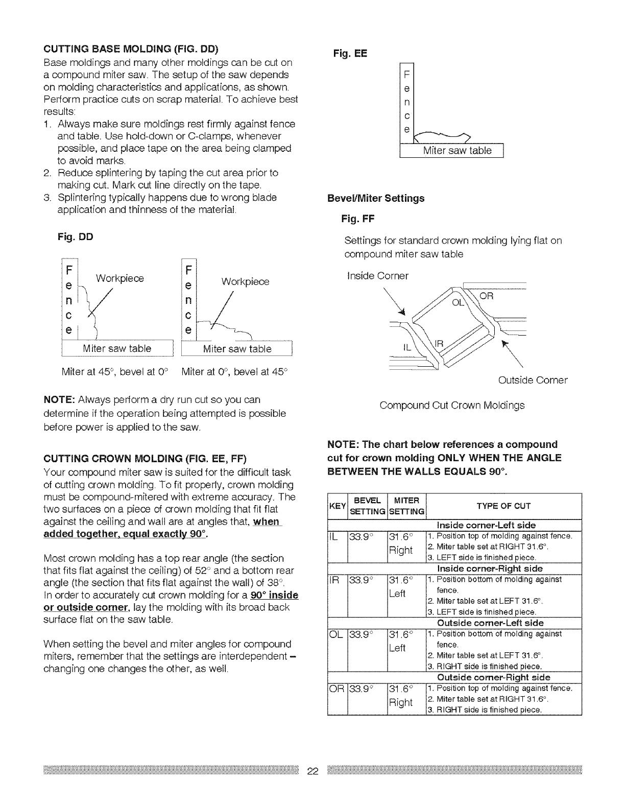
AUXILIARY WOOD FENCE (FIG. CC)
When making multiple or repetitive cuts that result in
cut-off pieces of one inch or less, it is possible for the
saw blade to catch the out=off piece and throw it out of
the saw or into the blade guard and housing, possibly
causing damage or injury. To minimize this, an auxiliary
wood fence can be mounted to your saw.
Holes are provided in the saw fence to attach an
auxiliary wood fence. This fence is to be constructed
of straight wood approximately 3/4 in. thick by 2-I/2 in.
high by 18 in. long.
Attach the wood fence securely and make a full depth
cut to make a blade slot.
Check for interference between the wood fence and the
lower blade guard. Adjust if necessary.
NOTE: This auxiliary fence is used only with the saw
blade in the 0° bevel position (90 ° to the table). The
auxiliary wood fence must be removed when bevel
cutting.
Fig. CC
2
Blade Slot
2I
CUTTINGBASEMOLDING (FIG. DD)
Base moldings and many other moldings can be cut on
a compound miter saw. The setup of the saw depends
on molding characteristics and applications, as shown.
Perform practice cuts on scrap material. To achieve best
results:
I. Always make sure moldings rest firmly against fence
and table. Use hold-down or C-clamps, whenever
possible, and place tape on the area being clamped
to avoid marks.
2 Reduce splintering by taping the cut area prior to
making cut. Mark cut line directly on the tape.
3. Splintering typically happens due to wrong blade
application and thinness of the material.
Fig. DD
Workpiece
Miter saw table ] I
F
eWorkpiece
C....
e°4
Miter saw table
Miter at 45°, bevel at 0° Miter at 0°, bevel at 45°
NOTE: Always perform a dry run cut so you can
determine if the operation being attempted is possible
before power is applied to the saw.
CUTTING CROWN MOLDING (FIG. EE, FF)
Your compound miter saw is suited for the difficult task
of cutting crown molding. To fit properly, crown molding
must be compound-mitered with extreme accuracy. The
two surfaces on a piece of crown molding that fit flat
against the ceiling and wall are at angles that, when
added tog eth#[_._qual exactly 90°.
Most crown molding has a top rear angle (the section
that fits flat against the ceiling) of 52° and a bottom rear
angle (the section that fits flat against the wall) of 38 °.
In order to accurately cut crown molding for a 90°inside
or outside corner, lay the molding with its broad back
surface flat on the saw table.
When setting the bevel and miter angles for compound
miters, remember that the settings are interdependent -
changing one changes the other, as well.
Fig. EE
-- Miter saw iabie q
Bevel/Miter Settings
Fig. FF
Settings for standard crown molding lying flat on
compound miter saw table
Inside Corner
\\OR
\
Outside Corner
Compound Cut Crown Moldings
NOTE: The chart below references acompound
cut for crown molding ONLY WHEN THE ANGLE
BETWEEN THE WALLS EQUALS 90 °.
KEYll BEVEL IMITER ITYPE OF CUT
inside corner-Left side
IL 339 ° 31.6 ° 1. Position top of molding against fence.
IRight 12.Miter table set at RIGHT 31.6 .
3. LEFT s de s t n shed p ece,
Inside corner=Right side
IR 33.9 ° 31.6 ° 1. Position bottom of molding against
I ILeft I fence'
2. Miter table set at LEFT 31.6 °.
3. LEFT side is finished p ece,
Outside comer-Left side
OL 33.9 ° 31.8 ° 1. Position bottom of molding against
I ILeft I fence'
I 12. Miter table set at LEFT 31.6 °.
_. RIGHT side is f n shed piece.
Outside comer-Right side
OR 133.9° 131.6 ° I1. Position top of molding against fence.
Right 2. Miter table set at RIGHT 31.6 ° .
22 _"

CROWN MOLDING CHART
Compound Miter Saw
Miter and Bevel Angle Settings
Wall to Crown Molding Angle
Angle Between
V//ajJs
67
68
69
?0
7i
72
73
52/38 ° C_own Molding
Miter Setting
4293
4239
4/ 85
41 32
4079
40 28
99 76
Bevei Setting
41 08
4679
40 50
4020
59 90
39 61
39 30
Miter Se_ting
46 89
46 35
45 81
4528
44 75
44 22
43 70
45/48 ° Crown M oldinc:}
Bevel Setting
3613
35 89
35 64
86640
35 15
34 89
34 64
74 5925 3908 4318 3538
75 42 66 34 12
76 42 15 33 86
77 41664 33660
78 4II8 3833
79 40662 3307
80 40 12 3280
81 39662 82 58
82 3918 32 25
83 58 663 31 98
84 3814 31 70
85 37666 3142
86 57 17 3I 34
87 36 669 38 86
38 74 38 89
38 24 38 39
37 74 3808
37 24 87 766
3675 5745
5627 37 !3
3579 368!
35 31 36 49
34 85 36 /7
54 36 35 866
3390 3552
3343 35i9
32 97 34 86
88 82 52 34 663 36 21 30 57
89 32(}7
90 31 62
91 31 17
92 30 78
93 8080
94 29 86
95 2943
96 29 09
97 2858
98 28 16
99 27 74
1066 27 32
2,420 3574
33 86 35 26
33 53 54 79
3319 3433
32 866 3386
32 51 33 40
32 I7 2,2 94
81 82 52 48
31 48 3202
3/ 13 31 58
36 78 51 13
30 43 30 668
3029
30 00
2971
2942
2913
28 83
28 664
28 24
2794
27 64
27 54
27 08
10I .26 91 .3008 . 3024 • 26 73
2650
2609
25 669
26 29
2489
2449
2410
23 71
2332
22 93
22665
227
21 79
29 73 2980
29 38 29 36
29 02 28 92
28 667 28 48
28 31 2805
27966 27662
2759 27 19
27 23 2677
26 87 26 54
26 51 25 92
26166 25660
25 78 25 08
25 42 24 666
102
163
104
105
106
]07
108
109
I !0
1/1
112
113
1 !4
2642
26612
258I
2550
2519
24 87
2456
24 24
23 93
23 661
2329
22 97
226666
115 21 42 25 066 24 25 2233
! 16 21 04 2468 2384 220I
1 I7 2067 24 31 2343 21 68
I I8 20 30 23 94 23 02 2I 36
119 1993 23 67 22 661 21 03
120 19 '37 23 29 22 2I 20 70
121 1920 2283 2180 20?,8
122 18 84 22 466 21 46 20 05
123 18 48 2209 2i 660 1972
52/38 ° Crown M )[ding 45/45" CF@/Sn Molding
Angle Between Miter Setting Bevel Setting Miter Setting Bevel Settin 9
\,_1/8118
124 18 13 21 7! 20 61 19 39
125 /7 77 2I 34 20 2I 19 06
I266 I7 42 2(} 96 I9¸81 18¸72
127 I7 66 20 59 19 42 18¸39
128 16 71 20 21 !9 03 I8 06
129 16 87
130 1602
131 15 67
132 1553
I33 14 99
134 14 66
i35 I4 50
136 1397
!37 !363
138 18 30
139 !2 96
140 12 63
141 I230
i42 II 97
143 11 64
19 88 18 64 17 72
I945 !825 !739
/9 07 i7 866 17 066
1869 !748 I67I
/8 3I 17 09 1638
/7 93 I66 7! 16604
/7 55 !632 15 70
I7/7 I5 94 15 366
1679 1556 !502
/66 40 I5/9 14 62
/6 02 14 81 14 34
/5 64 14 43 14 O0
16625 I486 15666
I4 87 13 68 1331
14 48 13 5I 12 97
144 . 1I 81 .14 09 .12 94 . 12 62
!466
1466
147
148
I49
1660
151
/52
I53
154
155
!099
10 66
1034
1061
9 669
9 37
9 05
8 73
841
8 09
777
1371 1257
/332 1220
12 93 1I 83
/254 11466
/2/6 11 69
/I 77 !0 73
1138 I036
10 99 !0 O0
1060 9668
/0 21 927
9 82 8 91
1566
i667
158
!59
160
1661
162
I63
i64
I65
166
167
168
169
170
I71
!72
178
174
175
1766
177
178
i79
!229
11 93
11 59
1124
10 89
16 566
1820
9 85
950
915
8 80
746 943 855 845
714 904 . 8T9 . 8166
885
8 26
786
? 47
708
6 69
638
5 90
55/
5!2
4 72
4 38
3 94
7 83
7 47
7!1
6675
6 39
6603
568
5 32
4 96
46I
425
3 96
3 _,4
7766
7 4O
7 05
66766
6 35
600
565
,5 30
4 94
4 59
4 24
3 89
3 53
6 82
651
6 20
5 88
5 57
5 26
4 95
4 63
432
401
370
339
3 08
2 77 3 54 3 19 3 10
247 315 283 283
215 275 248 247
185 286 212 212
1 54 1 97 177 177
1 23 1 668 1 41 1 41
092 I 18 1 66 1 666
0662 079 071 071
031 039 6635 035
23 _
MAINTENANCE
[,_ DANGER
Never put lubricants on the blade while it is
spinning.
[A WAR.. GI
•To avoid fire or toxic reaction, never use gasoline,
naphtha acetone, lacquer thinner or similar highly
volatile solvents to clean the miter saw.
•To avoid injury from unexpected starting or
electrical shock, unplug the power cord before
working on the saw.
•For your safety, this saw is double insulated. To
avoid electrical shock, fire or injury, use only
parts identical to those identified in the parts list.
Reassemble exactly as the original assembly to
avoid electrical shock.
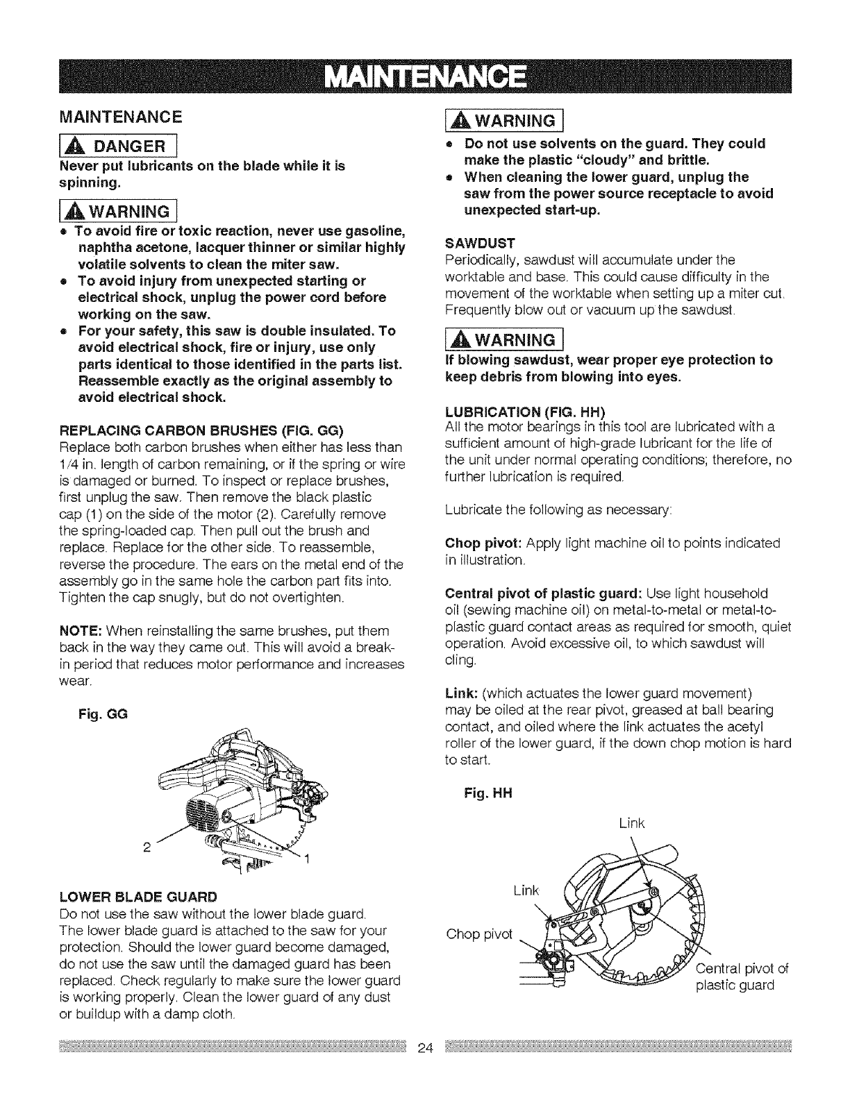
REPLACING CARBON BRUSHES (FIG. GG)
Replace both carbon brushes when either has less than
I/4 in. length of carbon remaining, or ff the spring or wire
is damaged or burned. To inspect or replace brushes,
first unplug the saw. Then remove the black plastic
cap (I) on the side of the motor (2). Carefully remove
the spring-loaded cap. Then pull out the brush and
replace. Replace for the other side. To reassemble,
reverse the procedure. The ears on the metal end of the
assembly go in the same hole the carbon part fits into.
Tighten the cap snugly, but do not overtighten.
NOTE: When reinstalling the same brushes, put them
back in the way they came out. This will avoid a break-
in period that reduces motor performance and increases
wear.
Fig. GG
LOWER BLADE GUARD
Do not use the saw without the lower blade guard.
The lower blade guard is attached to the saw for your
protection. Should the lower guard become damaged,
do not use the saw until the damaged guard has been
replaced. Check regularly to make sure the lower guard
is working properly. Clean the lower guard of any dust
or buildup with a damp cloth.
[AWAR"m"G]
=Do not use solvents on the guard. They could
make the plastic "cloudy" and brittle.
•When cleaning the lower guard, unplug the
saw from the power source receptacle to avoid
unexpected start-up.
SAWDUST
Periodically, sawdust will accumulate under the
worktable and base. This could cause difficulty in the
movement of the worktable when setting up a miter cut.
Frequently blow out or vacuum up the sawdust.
IAwAR"'JGI
if blowing sawdust, wear proper eye protection to
keep debris from blowing into eyes.
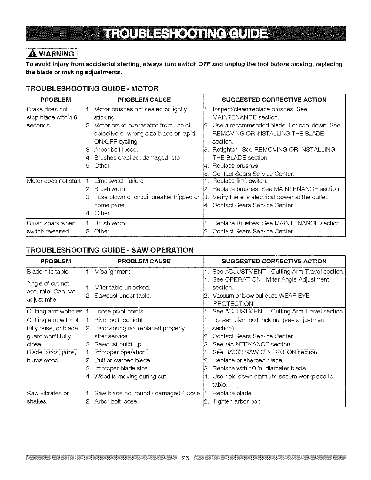
LUBRICATION (FIG. HH)
All the motor bearings in this tool are lubricated with a
sufficient amount of high-grade lubricant for the life of
the unit under normal operating conditions; therefore, no
further lubrication is required.
Lubricate the following as necessary:
Chop pivot: Apply light machine oil to points indicated
in illustration.
Central pivot of plastic guard: Use light household
oil (sewing machine oil) on metal-to-metal or metal-to-
plastic guard contact areas as required for smooth, quiet
operation. Avoid excessive oil, to which sawdust will
cling.
Link: (which actuates the lower guard movement)
may be oiled at the rear pivot, greased at bal! bearing
contact, and oiled where the link actuates the acetyl
roller of the lower guard, if the down chop motion is hard
to start.
Fig. HH
Link
Chop pivot
Link
_ntral pivot of
stic guard
24
[_ WARNING I
To avoid injury from accidental starting, always turn switch OFF and unplug the tool before moving, replacing
the blade or making adjustments.
PROBLEM
Brake does not
stop blade within 6
seconds.
TROU BLESHOOTING GUIDE - MOTOR
PROBLEM CAUSE
I. Motor brushes not sealed or lightly
sticking.
2. Motor brake overheated from use of
defective or wrong size blade or rapid
ON/OFF cycling.
Arbor bolt loose.
Brushes cracked, damaged, etc.
Other.
3,
4.
5.
Motor does not start 1.
2.
3.
4.
Brush spark when 1.
switch released. 2.
Limit switch failure
Brush worn.
Fuse blown or circuit breaker tripped on
home panel.
Other.
Brush worn.
Other.
SUGGESTED CORRECTIVE ACTION
I. Inspect/clean/replace brushes. See
MAINTENANCE section.
2. Use a recommended blade. Let cool down. See
REMOVING OR INSTALLING THE BLADE
section.
3. Retighten. See REMOVING OR INSTALLING
THE BLADE section.
4. Replace brushes.
5. Contact Sears Service Center.
1. Replace limit switch.
2. Replace brushes. See MAINTENANCE section.
3. Verify there is electrical power at the outlet.
4. Contact Sears Service Center.
1. Replace Brushes. See MAINTENANCE section.
2. Contact Sears Service Center.
TROU BLESHOOTING GUIDE - SAW OPERATION
PROBLEM
Blade hits table. 1.
Angle of cut not 1.
accurate. Can not 2.
adjust miter.
Cutting arm wobbles. I.
Cutting arm will not I.
fully raise, or blade 2.
guard won't fully
close. 3.
Blade binds, jams, 1.
burns wood. 2.
3.
4
Saw vibrates or 1.
shakes. 2.
PROBLEM CAUSE
Misalignment.
Miter table unlocked.
Sawdust under table.
Loose pivot points.
Pivot bolt too tight.
Pivot spring not replaced properly
after service.
Sawdust build-up
Imprope r operat ion.
Dull or warped blade.
Improper blade size.
Wood is moving during cut.
SUGGESTED CORRECTIVE ACTION
I. See ADJUSTMENT - Cutting Arm Travel section.
I. See OPERATION - Miter Angle Adjustment
section.
2. Vacuum or blow out dust. WEAR EYE
PROTECTION.
I. See ADJUSTMENT - Cutting Arm Travel section.
1. Loosen pivot bolt lock nut (see adjustment
section).
2. Contact Sears Service Center.
3. See MAINTENANCE section.
1. See BASIC SAW OPERATION section.
2. Replace or sharpen blade.
3. Replace with 10 in. diameter blade.
4. Use hold down clamp to secure workpiece to
table.
Saw blade not round /damaged /loose. 1. Replace blade.
Arbor bolt loose. 2. Tighten arbor bolt.
25

10INSUDINGCOMPOUNDMtTE.SAW MODEL.O137.212370
IA WARNINGI
When servicing use only CRAFTSMAN replacement parts. Use of any other parts many create aHAZARD or cause
product damage. Any attempt to repair or replace electrical parts on this Miter Saw may create aHAZARD unless repair
is done by a qualified service technician, Repair service is available at your nearest Sears Service Center.
PARTS LIST FOR SAW SCHEMATIC
I,D No Description Size
07WD SLIDE PLATE
O53R TRIGGER
063Z CORD CLAMP
OE>4W WARNING lABEL
0915 COMPRE_ION SPRING
OCES COMPRESSION SPRING
OCH3 COLLAR
OCKS SPRING WIRE
OCM3 FIOLD-DOWN C L,A_'V",PASS'Y
OC©H BEVEL STOP LOCKING IIANDLE
OCR6 SHAFT
OCl2 SH AN SLEEVE
03\/5 DUST BAG ASS'Y
ODHT SPRING GUARD
ODTH CENTER BO.T
0DVJ BLADE WRENCH
OFIXV L}N_AR MOTON BEABHG
O;4E FLAT W_HER @4,13 1
0J4M FL&T WASHER 012"21-1
0JBA N.AT WASHER 08'16-2.5
0.174 FLAT WASHER 1/4'5/&3/32
OJ7G FLAT WASH ER 3/8q9/32 1/8
0JA2 WAVE WASHER WW_6
0JB0 WAVE WASHER WW8
OJB© DISC SPRIN© WASHER 012
OJEX _RING
OJMN O-RING
OJMP ORING
OJPE HF;<, HD. BOLT MBN,O-20
OJPF HEX. H D. BOil MB* .0-25
04X7 HB<. SOC, SD SCREW M6'1.0_6
OJZN ARBOR BOLT MEN .25-20
OK2B HEK SOC. HD. CAP SCREW MBN.G16
0K2L HFX SOC. HD. CAP SCREW MEN 25-30
OK5D CR, RE. COUNT HD. SCREW M6N .0-20
0K74 CR, RE. TRUSS kID, SCREW MBN .0 8
OK7L CR. @E,ROUND WA£HER HD, SCRFY',_ M6"1,0 16
OK7X CR. RE. TRHSS HD. ROUND NECK SCREW M&N .0-10
OK7Z CR, RE. TRUSS HD. ROUND BIECK SCREW M6'1.0d4
OKA9 CR. RE. PAN liD, TAPPIN© SCREW M3'24-10
OKB7 CR. RE, PAN HD.TAPPINGSCREW M4N6 18
OKB9 CR. RE, PAN HD. IAPPINGSCREW MS* 6-10
OKBD CR. RE, PAN FID, TAPPINGSCREW M4q5-25
OKD6 OR. RE, PAN HD. SCREW M4"0.7-6
OKD7 CR. RE. PAN HD SCREW M4"0.7 10
OKDH CR. RE PAN HID. SCREW M5"0.6 6
OKDM CR. RE. PAN HID. SCREW M5'0.8-20
OKDR CR, RE. PAN HD. SCREW M5"0,8-10
OKDS CR. RE, PAN HD. SCREW M5_0,5-40
OKD] CR. RE, PAN HD. SCREW M6N ,0.5
OKDV CR. RE, PAN HD, SCREW MBN ,0d6
OKEO CR. RE, PAN HD. SCREW M6'1 0 40
OKKK CR, RE. PAN HD. ROUND NECKSCREW MBN .0L12
OKKX OR. RE, PAN HD. ROUND NECK SCREW M5"0,6- 14
OKMR HD<. NU[ M5'0,8 T=4
OKMS HFX. NUT MBN ,0 T-5
OK©W LOCK NUT ff,"@_O,8T-5
OK©X NU1 M@'1.0 T=6
OKRO NUT M12* 1.75 1=12
OKR4 LOCK NUT MEN 25 T 8,
OKT© CABLE CLAf,_I P
0KTS CABLE CLAMP
OKUW TERMINAL
OLU2 LIMIT SWITCH
0@Q1 CORD GUARD
OS!S COLLAR
OS2B CR. RE, PAN HD. TAPPINGSCREW M6 * .0-25
OSTZ TRADE-MARK LABEL
OU03 HE>(, 5OC HD, CAP SCREW
23LN KNOB HANDLE
23N F ARBOR COLLAR
Qty I,D No Qty
":" 23U3
250Z
25TF
262V
26LU
290M
2B5S
2KG
2BLK
2BST
2BTI
2BTV
2 2C3,7
1 2C_U
1 2CD2
} 2CD7
6 2D92
2D©C
2 2D©D
2 2DUY
2DWF
2DWG
2DWH
2DWJ
2 2DWK
I 2DWL
8 2DWP
1 2DWQ
7 2DWR
4 2DWS
2DWV
1 2DWX
2 2DWY
2 2DWZ
2 2DXO
1 2DX2
2 2DX4
1
4
5 2DX9
B, 2DXA
2 2DXF
1
3
1 2E63
2
4
2 2EU9
2EUA
I 2EXC
1 2EYT
4 2EYU
1 2EYV
4 2F39
2F7P
2FSN
2FEE
2FCF
2 2JAK
1 2JAP
1 2JL3
I 2JNN
2 2JNP
12JNQ
2 2K,SQ
I 2K96
2
Description Size
SPRING PIN
HEX. SOCKET HD. CAP SCREW M5'O,8 35
MriER BAR
STOP BLOCK (LEFT) #23
STOP BLOCK (RIGHT) #23
ANCHOR PLATE
WARNING lABEL
CLAMP BOLT
COMPRESSION SPR!IIO
WARN]N G LABEL
HEX. HD. BOLE t,_lO* 1,5-75
SHAFI PIVC£
COLLAR
FENCE #AW
COtLAR
EX1ENTION WiNG #AW
EXTENTION WING #AW
KNOB
COMPRESSION _<PRING
SPRING PIN
CONTROLLER ASS'Y
MOTOR HANDLE
MO1OR HANDLE
LEAD WIRE ASS'Y
BASE # A)7,,/
TAB LE #AW
SUPPOR[ #AW
[ABLE INkiER1"
TABLE INSERT
PUJNGER HAN DLE
NEEDLE POINTER
N EEDLE POINTER
ARM-M ITER # AW
BEARING COVER
CLAMP BOLT
SLIDE BAR SEAT (FRONT} #AW
SLIDING RAIL
SLIDE-BAR SEAl (REAR) #06
LEVER
SLID_BAR BLADE GUARD
PC GLARD
LEVER
ARM #AW
SEGMENT HADELE
COVER
SEGMEN1 HADELE
MCFTOR
BRACING PLATE #AW
ROCKER SWITCH
K)RSION SPRING
CUN'ER SHAFT GUARD #AW
STEEL GUARD
PLASTIC GUARD
LOCAr ION PIN
POWER CABLE
CR. RE, PAN lID.TAPPING SCREW B-a5*12_30
SPRING PIN
CLEVIS PIN
LASER ASS'Y
STICKER
BRACKET TIlT
II[NNG SCALE
LOCKING HANDLE ASS'Y
BLADE
OPERATOR'S MANUAL
lABEL
ROCKER SWITCH
TRADEMARK LABEL
WARNING, LABEL
WARNING LABEL
26 _

10 IN. SLIDING COMPOUND MITER SAW MODEL NO. 137.212370
SCHEMATIC FOR SAW
OJXT,
2DUY
_DXO
2DXA
_DX5
0OJBO K96
@2ESH
OCM3
EJL3 {]TWD
_DWL
@2C37
27
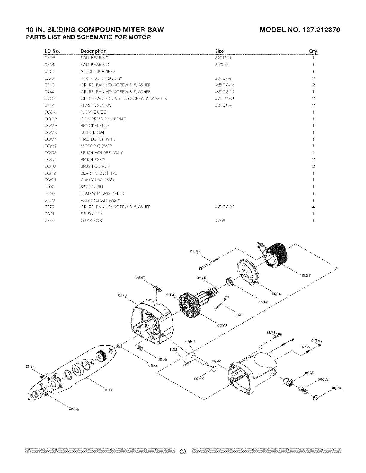
10 IN. SLiDiNG COMPOUND MITER SAW MODEL NO. 137.212370
PARTS LIST AND SCHEMATIC FOR MOTOR
I.D No. Description
OHVS BALL BEARING
OHVU BALi=BEARING
OHX9 NEEDLE BEAR NG
OJX2 HEX. SOC SETSCREW
0K43 CR. RE. PAN HD. SCREW & WASHER
0K44 CR, RE. PAN biD. SCREW & WASqER
OKCP CR. RE,PAN HD.TAPP NGSCREW & WASHER
OKLA PLASTIC SCREW
OQ9K FiOW GLIDE
OQGR COMPRESSION SPRING
OQME BRACKET STOP
OOMK R/. BBERCAP
O©MY PROTECTOR WIRE
OQMZ MOTOR COVER
O©©S BRUSH HOLDER AgS'Y
O©©T BRUSH ASS'Y
O©RO BRUSH COVER
O(DR2 BEARING BUSHING
OOYU ARMATURE ASS'Y
1102 SPRING P!N
116D LEAD WIRE A$8'Y RED
21JM ARBOR SHAFT ASS'Y
2B79 CR. RE. PAN HD. SCREW & WASHER
2D21 FIELD A,SS'Y
2E70 GEAR BOX
Size
6201ZLU
6200Z
M5'0.8-6
M5'0.8 1,5
M5'0.8 12
MS* 12-60
M5"0,8-6
M5"0.8_35
#AW
Qfy
I
)
1
2
2
1
2
2
1
1
1
1
1
1
2
2
2
1
1
1
1
1
4
1
1
0K44
£ETO
OQMY

29 _

Your Home
For repair - in your home - of all major brand appliances,
lawn and garden equipment, or heating and cooling systems,
no matter who made it, no matter who sold it!
For the replacement parts, accessories and
owner's manuals that you need to do-it-yourself.
For Sears professional installation of home appliances
and items like garage door openers and water heaters.
1-800-4-MY-HOME e (1-800-469-4663)
Call anytime, day or night (U.S.A. and Canada)
www,sears.com www.sears.ca
Our Home
For repair of carry-in items like vacuums, lawn equipment,
and electronics, call or go on-line for the location of your nearest
Sears Parts & Repair Center.
1-800-488-1222
Call anytime, day or night (U.S.A. only)
www.sears.com
To purchase a protection agreement (U.S.A.)
or maintenance agreement (Canada) on a product serviced by Sears:
1-800-827-6655 (U.S.A.) 1-800-361-6665 Canada)
Para pedir servicio de reparaci6n
a domicilio, y para ordenar piezas:
1-888-SU-HOGAR _
(1-888-784-6427)
Au Canada pour service en frangais:
1=800=LE-FOYER M_'
(1-800-533-6937)
www.sears.ca
_A SM
® Registers] Trademark /Trademaik /Service Mark of Sears Brands LLC
M
® Marca Regis_ada / ' Marca de Fbbrica /s Marca de Servicio de Sears Brands, LLC
MC MD
Marque de commerce /Marque d6pos6e de Sears BrancN, LIC © Sears Brands, ItC
