Craftsman 16 Variable Speed Scroll Saw 21602 Owners Manual 216020 SS163VRC 052608 English
Craftsman-137-21602-Users-Manual-161120 craftsman-137-21602-users-manual-161120
13721602 93489599-215c-4b6b-a7ef-2dd36bafc999 Craftsman Saw 137.21602 User Guide |
2015-03-28
: Craftsman Craftsman-16-Variable-Speed-Scroll-Saw-21602-Owners-Manual-661551 craftsman-16-variable-speed-scroll-saw-21602-owners-manual-661551 craftsman pdf
Open the PDF directly: View PDF ![]() .
.
Page Count: 36
1 1
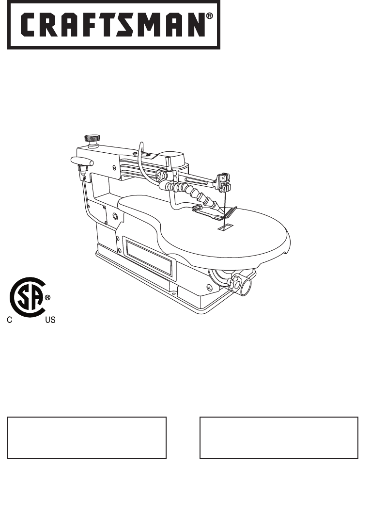
Operator’s Manual
16 in. VARIABLE SPEED
SCROLL SAW
Model No. 137.216020
CAUTION:
Before using this Scroll Saw,
read this manual and follow
all its Safety Rules and
Operating Instructions
● Safety Instructions
● Installation
● Operation
● Maintenance
● Parts List
Customer Help Line
For Technical Support
1-800-843-1682
Sears Parts &
Repair Center
1-800-488-1222
Sears, Roebuck and Co., Hoffman Estates, lL 60179 USA
Visit our Craftsman website: www.sears.com/craftsman
Part No. 137216020001 Printed in China

2 3
2 3
CRAFTSMAN ONE YEAR FULL WARRANTY
If this Craftsman tool fails due to a defect in material or workmanship within
one year from the date of purchase, call 1-800-4-MY-HOME R to arrange for
free repair (or replacement if repair proves impossible).
This warranty applies for only 90 days from the date of purchase if this product
is ever used for commercial or rental purposes.
This warranty does not include expendable parts, such as lamps, batteries,
bits or blades.
This warranty gives you specific legal rights, and you may also have other
rights which vary from state to state.
Sears, Roebuck and Co., Hoffman Estates, IL 60179
2008/05
TABLE OF CONTENTS
SECTION PAGE
Warranty ................................................................................................. 2
Product Specifications ............................................................................ 3
Symbols................................................................................................... 4
Power Tool Safety ...................................................................................5
Scroll Saw Safety .................................................................................... 8
Electrical Requirements and Safety ........................................................ 10
Accessories and Attachments .................................................................12
Tools Needed for Assembly .................................................................... 12
Carton Contents ...................................................................................... 13
Know Your Scroll Saw............................................................................. 14
Glossary of Terms ................................................................................... 15
Assembly and Adjustments ..................................................................... 17
Operation ................................................................................................ 26
Maintenance ........................................................................................... 31
Troubleshooting Guide ........................................................................... 32
Parts List ................................................................................................. 34
WARRANTY
WARNING
!
Some dust created by using power tools contains chemicals known to the state
of California to cause cancer and birth defects or other reproductive harm.
Some examples of these chemicals are:
● Lead from lead-based paints
● Crystalline silica from bricks, cement and other masonry products
● Arsenic and chromium from chemically treated lumber
Your risk from these exposures varies, depending on how often you do
this type of work. To reduce your exposure to these chemicals, work in a
well ventilated area and work with approved safety equipment such as dust
masks that are specially designed to filter out microscopic particles.

2 3
2 3
To avoid electrical hazards, fire hazards or damage to the tool, use proper
circuit protection.
This tool is wired at the factory for 110-120 Volt operation. It must be
connected to a 110-120 Volt / 15 Ampere time delay fuse or circuit breaker.
To avoid shock or fire, replace power cord immediately if it is worn, cut or
damaged in any way.
Before using your tool, it is critical that you read and understand these
safety rules. Failure to follow these rules could result in serious injury to
you or damage to the tool.
PRODUCT SPECIFICATIONS
MOTOR
Power Source ............................................................. 1.6 A, 120 V AC, 60 Hz
Speed Control............................................................. Electric
TABLE
Tilt................................................................................ 450 Left
SAWDUST BLOWER................................................. Yes
BLADE
Speed.......................................................................... 400~1600 SPM
Type............................................................................. Pin-end or Plain-end
Length.......................................................................... 5 in.
Depth of Throat............................................................ 16 in.
Blade Stroke................................................................ 3/4 in.
Depth of 450 Cut.......................................................... 1 in.
Depth of 900 Cut.......................................................... 2 in.
WARNING
!

4 5
4 5
WARNING ICONS
Your power tool and its Operator’s Manual may contain “WARNING ICONS”
(a picture symbol intended to alert you to, and/or instruct you how to avoid,
a potentially hazardous condition). Understanding and heeding these
symbols will help you operate your tool better and safer. Shown below are
some of the symbols you may see.
SAFETY ALERT: Precautions that involve your safety.
PROHIBITION
WEAR EYE PROTECTION: Always wear safety goggles or safety
glasses with side shields.
READ AND UNDERSTAND OPERATOR’S MANUAL: To reduce the risk
of injury, user and all bystanders must read and understand operator’s
manual before using this product.
SUPPORT AND CLAMP WORK
KEEP HANDS AWAY FROM BLADE: Failure to keep your hands away
from the blade will result in serious personal injury.
DANGER
!
WARNING
!
CAUTION
!
CAUTION
DANGER: indicates an imminently hazardous situation
which, if not avoided, will result in death or serious injury.
WARNING: indicates a potentially hazardous situation
which, if not avoided, could result in death or serious injury.
CAUTION: indicates a potentially hazardous situation which,
if not avoided, may result in minor or moderate injury.
CAUTION: used without the safety alert symbol indicates
a potentially hazardous situation which, if not avoided,
may result in property damage.
SYMBOLS

4 5
4 5
POWER TOOL SAFETY
GENERAL SAFETY INSTRUCTIONS
BEFORE USING THIS POWER TOOL
Safety is a combination of common
sense, staying alert and knowing how
to use your power tool.
To avoid mistakes that could cause
serious injury, do not plug the tool in
until you have read and understood
the following.
1. READ and become familiar
with the entire Operator’s
Manual. LEARN the tool’s
application, limitations and
possible hazards.
2. KEEP GUARDS IN PLACE and in
working order.
3. REMOVE ADJUSTING KEYS
AND WRENCHES. Form the habit
of checking to see that keys and
adjusting wrenches are removed
from the tool before turning ON.
4. KEEP WORK AREA CLEAN.
Cluttered areas and benches invite
accidents.
5. DO NOT USE IN DANGEROUS
ENVIRONMENTS. Do not use
power tools in damp locations, or
expose them to rain or snow. Keep
work area well lit.
6. KEEP CHILDREN AWAY. All
visitors and bystanders should be
kept a safe distance from work
area.
7. MAKE WORKSHOP CHILD
PROOF with padlocks, master
switches or by removing starter
keys.
8. DO NOT FORCE THE TOOL. It will
do the job better and safer at the
rate for which it was designed.
9. USE THE RIGHT TOOL. Do not
force the tool or an attachment
to do a job for which it was not
designed.
10. USE PROPER EXTENSION
CORDS. Make sure your extension
cord is in good condition. When
using an extension cord, be sure
to use one heavy enough to carry
the current your product will draw.
An undersized cord will result in
a drop in line voltage and in loss
of power which will cause the tool
to overheat. The table on page
11 shows the correct size to use
depending on cord length and
nameplate ampere rating. If in
doubt, use the next heavier gauge.
The smaller the gauge number, the
heavier the cord.
WARNING
!

6 7
6 7
11.
WEAR PROPER APPAREL. Do
not wear loose clothing, gloves,
neckties, rings, bracelets or other
jewelry which may get caught in
moving parts. Nonslip footwear is
recommended. Wear protective
hair covering to contain long hair.
12. ALWAYS WEAR EYE
PROTECTION. Any power
tool can throw foreign
objects into the eyes and
could cause permanent
eye damage. ALWAYS wear Safety
Goggles (not glasses) that comply
with ANSI Safety standard Z87.1.
Everyday eyeglasses have only
impact–resistant lenses. They
ARE NOT safety glasses. Safety
Goggles are available at Sears.
NOTE: Glasses or goggles not in
compliance with ANSI Z87.1 could
seriously injure you when they
break.
13. WEAR A FACE MASK OR DUST
MASK. Sawing operation produces
dust.
14. SECURE WORK. Use clamps or
a vise to hold work when
practical. It is safer than
using your hand and
it frees both hands to
operate the tool.
15. DISCONNECT TOOLS FROM
POWER SOURCE before servicing,
and when changing accessories
such as blades, bits and cutters.
16. REDUCE THE RISK OF
UNINTENTIONAL STARTING.
Make sure switch is in the OFF
position before plugging the tool in.
17. USE RECOMMENDED
ACCESSORIES. Consult
this Operator’s Manual for
recommended accessories. The
use of improper accessories may
cause risk of injury to yourself or
others.
18. NEVER STAND ON THE TOOL.
Serious injury could occur if the
tool is tipped or if the cutting tool is
unintentionally contacted.
19. CHECK FOR DAMAGED PARTS.
Before further use of the tool, a
guard or other part that is damaged
should be carefully checked to
determine that it will operate
properly and perform its intended
function – check for alignment of
moving parts, binding of moving
parts, breakage of parts, mounting
and any other conditions that may
affect its operation. A guard or
other part that is damaged should
be properly repaired or replaced.

6 7
6 7
20. NEVER LEAVE THE TOOL
RUNNING UNATTENDED. TURN
THE POWER “OFF”. Do not walk
away from a running tool until the
blade comes to a complete stop
and the tool is unplugged from the
power source.
21. DO NOT OVERREACH. Keep
proper footing and balance at all
times.
22. MAINTAIN TOOLS WITH CARE.
Keep tools sharp and clean for best
and safest performance. Follow
instructions for lubricating and
changing accessories.
23. WARNING: Dust generated from
certain materials can be hazardous
to your health. Always operate saw
in well-ventilated area and provide
for proper dust removal.
24. People
with electronic devices, such as
pacemakers, should consult their
physician(s) before using this
product. Operation of electrical
equipment in close proximity to
a heart pacemaker could cause
interference or failure of the
pacemaker.
DANGER
!

8 9
8 9
7. YOUR SCROLL SAW MUST
BE SECURELY FASTENED to
a stand or workbench. If there
is any tendency for the stand
or workbench to move during
operation, the stand or workbench
MUST be fastened to the floor.
8. THIS SCROLL SAW is intended for
indoor use only.
9. TENSION BLADE PROPERLY
before starting the saw. Recheck
and adjust tension as needed.
10. BLADE TEETH MUST POINT
downward toward the table.
11. TABLE MUST BE CLEARED of all
debris before operating saw. Do not
perform lay out, set up or assemble
work on the table when the saw is
in operation.
12. TO PREVENT INJURIES, avoid
awkward hand or finger positions,
where a sudden slip could cause a
hand to move into the blade when
operating the saw.
13. HOLD WORKPIECE FIRMLY
against the table top.
14. NEVER CUT MATERIAL that is too
small to be held safely.
15. DO NOT USE dull or bent blades.
SCROLL SAW SAFETY
1. READ AND UNDERSTAND all
safety instructions and operating
procedures throughout the manual.
2. DO NOT OPERATE the Scroll Saw
until it is completely assembled
and installed according to the
instructions.
3. SHOULD any part of Scroll Saw
be missing, damaged, or fail in any
way, or any electrical component
fail to perform properly, shut off the
switch and remove the plug from
the power supply outlet. Replace
missing, damaged, or failed parts
before resuming operation.
4. IF YOU ARE NOT thoroughly
familiar with the operation of a
Scroll Saw, obtain advice from
your supervisor, instructor or other
qualified person.
5. SERIOUS INJURY could occur if
the tool tips over or you accidentally
hit the cutting tool. Do not store
anything above or near the tool.
6. AVOID INJURY from unexpected
saw movement. Place the saw on
a firm level surface where the saw
does not rock and bolt or clamp the
saw to its support.

8 9
8 9
16. TURN THE SAW OFF AND
UNPLUG THE CORD if the blade
binds in the saw kerf while being
backed out of the workpiece,
usually caused by sawdust
clogging the kerf. If this happens,
turn off the scroll saw and unplug
the power cord. Wedge open the
kerf and back the blade out of the
workpiece.
17. DO NOT feed the material too
fast while cutting. Only feed the
workpiece at the rate the saw will
cut.
18. TURN THE POWER OFF, remove
the switch key and make sure the
scroll saw comes to a complete
stop before installing or removing
an accessory, and before leaving
the work area.
19. DO NOT START the saw with
workpiece pressing against the
blade. Slowly feed the workpiece
into the moving blade.
20. WHEN CUTTING a large
workpiece, MAKE SURE the
material is supported at table
height.
21. EXERCISE CAUTION when
cutting workpieces that are round
or irregularly shaped. Round items
will roll and irregularly shaped
workpieces can pinch the blade.
22. ALWAYS release blade tension
before loosening the blade holder
screw.
23. MAKE CERTAIN table tilting lock
is tightened before starting the
machine.
24. NEVER REACH under the scroll
saw table when motor is running.
25. CHECK FOR DAMAGED PARTS
before each use. Check for
alignment of moving parts, binding
of moving parts, breakage of parts,
mounting or any other conditions
that may affect operation. Parts that
are damaged should be properly
repaired or replaced before using
the tool.
26. THINK SAFETY.

10 11
10 11
GUIDELINES FOR EXTENSION
CORDS
USE THE PROPER EXTENSION
CORD. Make sure your extension cord
is in good condition. Use an extension
cord heavy enough to carry the current
your product will draw. An undersized
cord will cause a drop in line voltage
resulting in loss of power, overheating
and burning out of the motor. The
table on the right shows the correct
size to use depending on cord length
and nameplate ampere rating. If in
doubt, use the next heavier gauge. The
smaller the gauge number, the heavier
the cord.
Make sure your extension cord is
properly wired and in good condition.
Always replace a damaged extension
cord or have it repaired by a qualified
technician before using it. Protect your
extension cords from sharp objects,
excessive heat and damp or wet areas.
Use a separate electrical circuit for
your tool. This circuit must not be less
than #18 wire with a 1.6 A time-lag
fuse. NOTE: When using an extension
cord on a circuit with a #18 wire, the
extension cord must not exceed 25 feet
in length. Before connecting the motor
to the power line, make sure the switch
is in the off position and the electric
current is rated the same as the current
stamped on the motor nameplate.
Running at a lower voltage will damage
ELECTRICAL REQUIREMENTS AND SAFETY
GROUNDING INSTRUCTIONS
IN THE EVENT OF A MALFUNCTION
OR BREAKDOWN, grounding provides
a path of least resistance for electric
currents and reduces the risk of electric
shock. This tool is equipped with an
electrical cord that has an equipment-
grounding conductor and a grounding
plug. The plug must be plugged into
a matching receptacle that is properly
installed and grounded in accordance
with all local codes and ordinances.
DO NOT MODIFY THE PLUG
PROVIDED. If it will not fit the
receptacle, have the proper receptacle
installed by a qualified electrician.
IMPROPER CONNECTION of the
equipment grounding conductor can
result in risk of electric shock. The
conductor with the green insulation
(with or without yellow stripes) is the
equipment grounding conductor. If
repair or replacement of the electrical
cord or plug is necessary, do not
connect the equipment grounding
conductor to a live terminal.
CHECK with a qualified electrician or
service person if you do not completely
understand the grounding instructions,
or if you are not certain the tool is
properly grounded.
USE only three-wire extension cords
that have three-pronged grounding
plugs with three-pole receptacles that
accept the tool’s plug. Repair or replace
damaged or worn cords immediately.
10 11
10 11
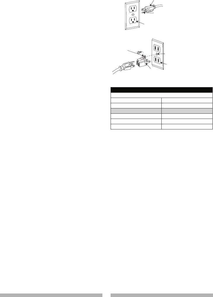
Fig. 1
Fig. 2
MINIMUM GAUGE FOR EXTENSION CORDS (AWG)
(When using 120 volts only)
Ampere Rating Total length of Cord
More Than Not More Than 25ft. 50ft. 100ft. 150ft.
0 6 18 16 16 14
6 10 18 16 14 12
10 12 16 16 14 12
12 16 14 12 Not Recommended
the motor. This tool is intended for use
on a circuit that has a receptacle like
the one illustrated in Fig. 1.
Fig. 1 shows a three-pronged electrical
plug and receptacle that has a
grounding conductor. If a properly
grounded receptacle is not available,
an adapter (sold separately) (Fig. 2)
can be used to temporarily connect
this plug to a two-contact grounded
receptacle. The adapter (Fig. 2) has a
rigid lug extending from it that MUST
be connected to a permanent earth
ground, such as a properly grounded
receptacle box.
CAUTION
●
In all cases, make certain the
receptacle is properly grounded. If
you are not sure, have a qualified
electrician check the receptacle.
●
This tool is for indoor use only.
Do not expose to rain or use in
damp locations.
●
This tool must be grounded while
in use to protect the operator from
electric shock.
●
Never remove the grounding
prong from the power cord. If
damaged, discontinue use of unit
and contact customer service for
a replacement cord.
Three-Pronged Plug
Grounding Prong
Properly Grounded
Three-Pronged Receptacle
Grounding Lug Make sure this is
connected to a
known ground.
Two-Pronged
Receptacle
Adapter
12 13
12 13
AVAILABLE ACCESSORIES
● To avoid injury, do not attempt
to modify this tool or create
accessories not recommended
for use with this tool. Any such
alteration or modification is
misuse and could result in a
hazardous condition leading to
possible serious injury.
● Use only accessories
recommended for this scroll
saw. Follow instructions that
accompany accessories. Use of
improper accessories may cause
hazards.
Visit your Sears Hardware Department
or see the Sears Power and Hand Tool
Catalog for the following accessories:
ITEM
Pin-end saw blades
Plain-end saw blades
Sears may recommend other
accessories not listed in this manual.
See your nearest Sears store or
Power and Hand Tool Catalog for other
accessories.
Do not use any accessory unless you
have completely read the instruction or
Operator’s Manual for that accessory.
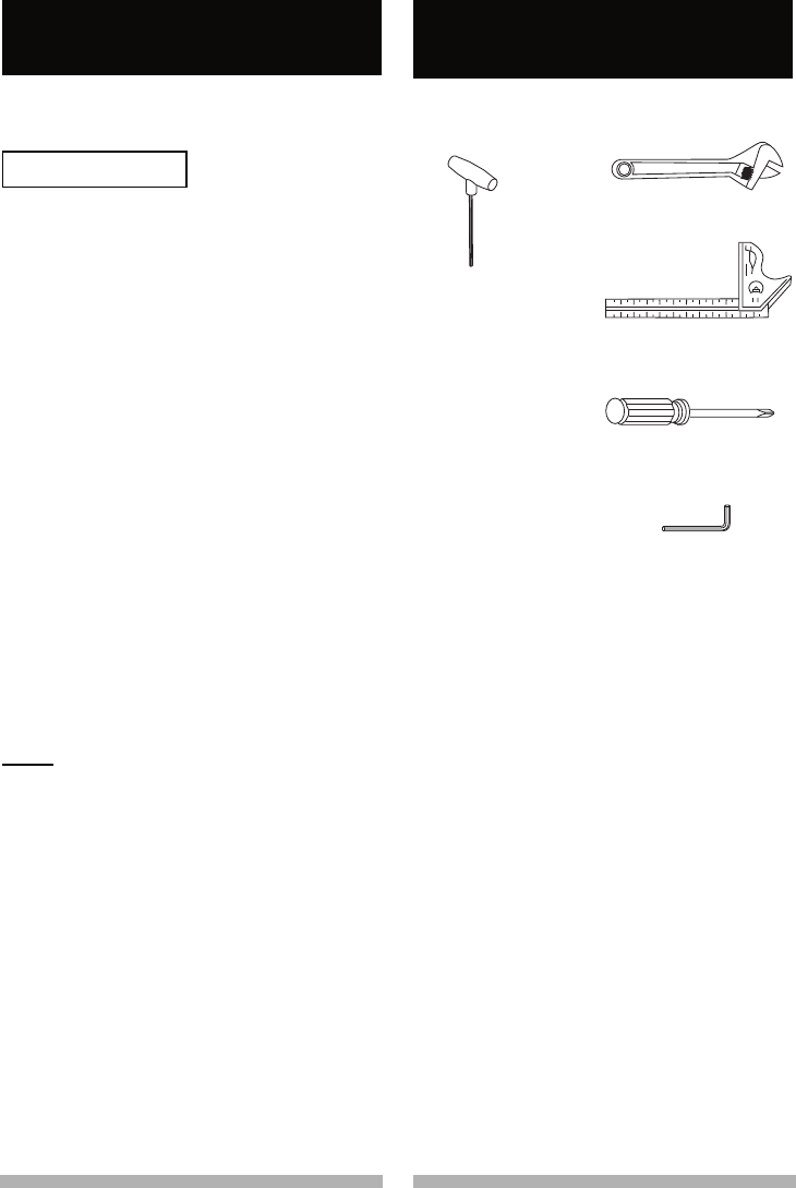
Adjustable Wrench
Phillips Screwdriver
Combination Square
Not SuppliedSupplied
3 mm T-Wrench
ACCESSORIES AND
ATTACHMENTS
TOOLS NEEDED FOR ASSEMBLY
AND ADJUSTMENT
5 mm Hex Wrench
WARNING
!
12 13
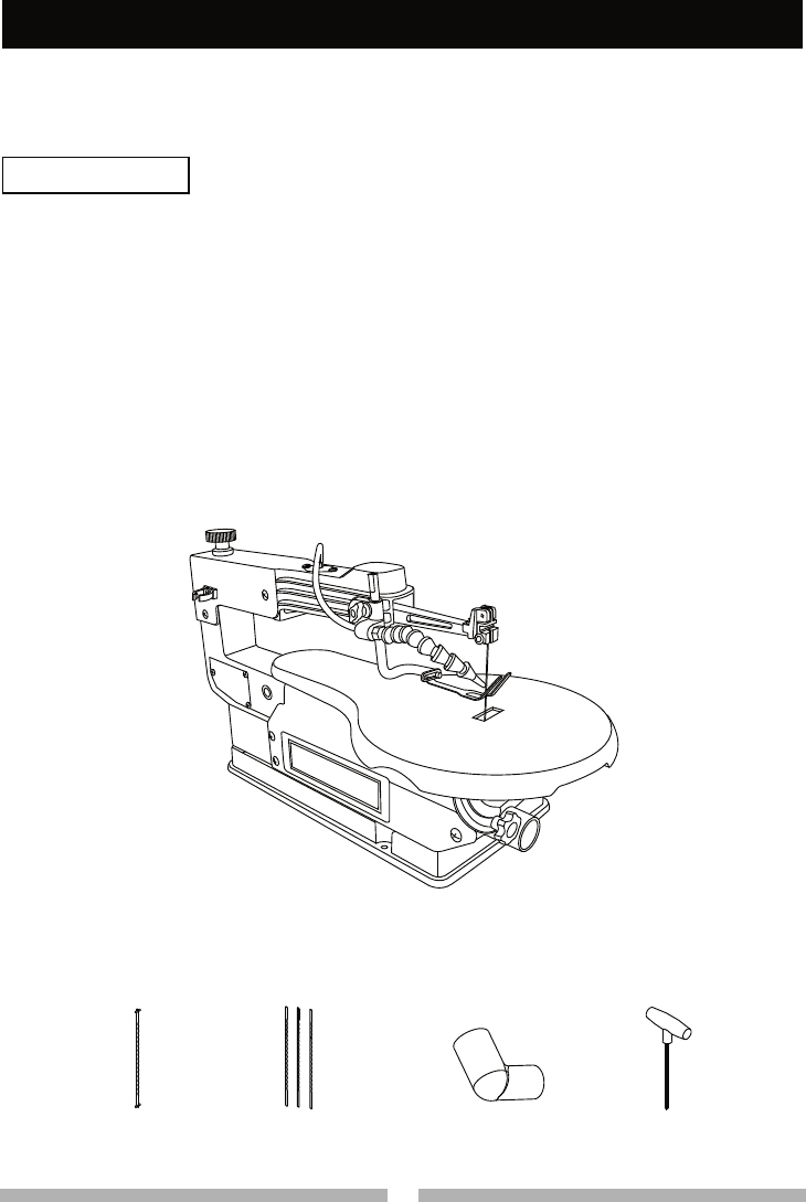
12 13
Scroll Saw
3 mm T-wrench
Pin-end saw blade Plain-end
saw blades
Dust port
adapter
UNPACKING AND CHECKING
CONTENTS
● To avoid injury, if any part is
missing or damaged, do not plug
the scroll saw in until the missing
or damaged part is replaced, and
assembly is complete.
● To avoid fire and toxic reaction,
never use gasoline, naphtha,
acetone, lacquer, thinner or
similar highly volatile solvents to
clean the scroll saw.
CARTON CONTENTS
1. Remove the scroll saw from the
carton by lifting the saw by the back
of the upper frame.
2. Place the saw on a secure
stationary work surface.
3. Separate all parts from the packing
material. Check each one with the
illustration below to make certain
all items are accounted for before
discarding any packing material.
CAUTION: Do not lift this saw by the
arm that holds the blade, this may
result in damage to the tool.
WARNING
!
14 15
14 15
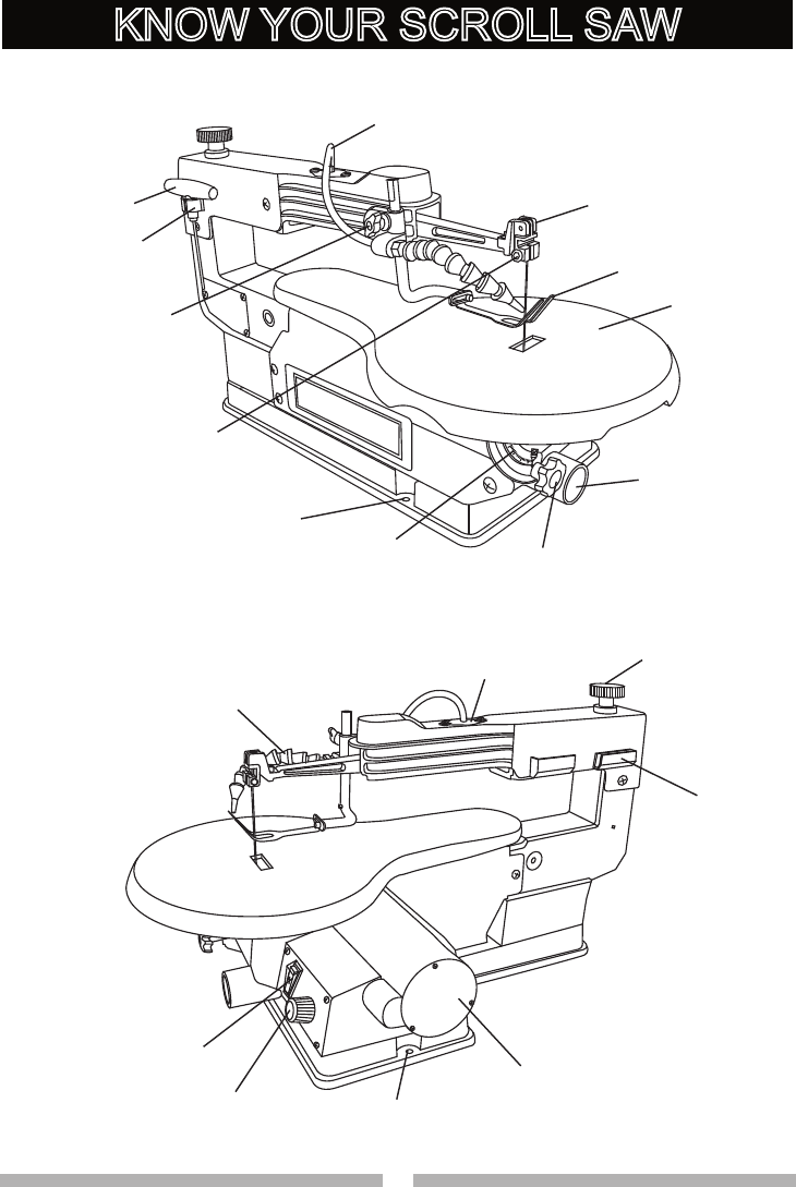
Sawdust Blower Tubing
Blade Guard Foot
Lock Knob
T-Wrench
T-Wrench Holder
Upper Arm
Blade Guard Foot
Worktable
Sawdust
Collection Port
Mounting Holes
Table Lock Knob
Bevel Scale
Blade Holder Lock Screw
Bellows Seat
Sawdust Blower
Variable Speed
Control Knob Mounting Holes
ON/OFF Switch
Tension Knob
Blade Storage
Motor
KNOW YOUR SCROLL SAW

14 15
14 15
GLOSSARY OF TERMS
SCROLL SAW TERMS
BEVEL SCALE – Represents the
degree of table angle from 0° to 45°
when the table is tilted for bevel cutting.
BLADE GUARD FOOT – Guards the
blade and keeps your workpiece from
rising. Helps protect fingers from blade
contact.
BLADE GUARD FOOT LOCK KNOB
– Allows you to raise or lower the foot
and lock it at the desired height.
BLADE HOLDERS – Retain and
position the blades.
BLADE STORAGE – Provides
convenient easy access to extra blades
or wrenches.
QUICK RELEASE TENSION LEVER
– Quickly loosens and retightens
the blade to its original tension. The
tension lever quickly sets and resets
the blade tension when performing
interior cutting operations or changing
blades.
SAWDUST BLOWER – Keeps
sawdust from covering the line of sight
for more accurate cuts. The best results
occur when the blower tube is directed
toward the blade and workpiece.
SAWDUST COLLECTION PORT –
Allows vacuum hose or attachments to
be used to remove the sawdust from
under the table and base.
TABLE LOCK KNOB – Securely locks
the table at the angle desired for bevel
cutting.
VARIABLE SPEED CONTROL
KNOB – Variable switch dial allows
greater versatility when cutting a
variety of materials. Adjust the speed
to the desired setting, between 400
to 1600 strokes per minute (SPM), by
turning the control knob clockwise or
counterclockwise.
WOODWORKING TERMS
BLADE TOOTH SET – The total width
the blade will cut based on the distance
from the outside point of one bent tooth
to the outside point of the next bent
tooth establishing set of teeth.
DEFLECTION – Slight movement of
blade in the horizontal direction while
the blade is moving inline during cutting
operation. This may be caused by the
blade following the grain or the path of
least resistance.
FEED – Rate of moving material to be
cut into the blade.
KERF – The slot cut by the blade.
Sawdust
Collection Port
Blade Storage
16 17
16 17
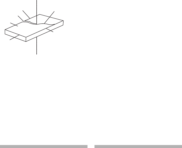
Kerf
Leading edge Saw blade path
Trailing edge
Workpiece
Surface
LEADING EDGE – The front edge of
the workpiece that is guided into the
blade.
SAW BLADE PATH – Area or line of
sight of the workpiece moving in line
toward the saw blade edge.
SURFACE – Top of workpiece being
cut.
TRAILING EDGE – The end of the
workpiece edge last cut by the saw
blade.
WORKPIECE – Material on which the
cutting operation is being performed.
16 17
16 17
Estimated Assembly Time: 5-10
minutes
To avoid injury, do not connect this
scroll saw to the power source until
it is completely assembled and
adjusted and you have read and
understood this instruction manual.
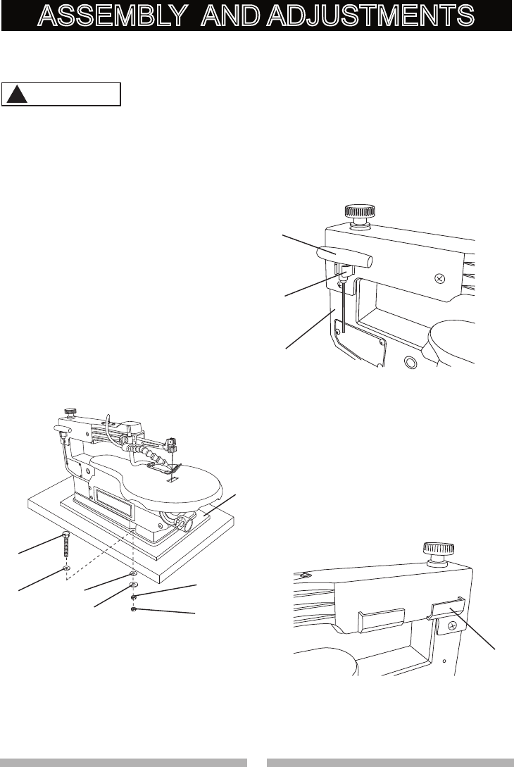
MOUNTING SCROLL SAW TO WORK
SURFACE (FIG. A)
1. If mounting the scroll saw to a
workbench, a solid wood bench is
preferred over a plywood board to
reduce noise and vibration.
2. The hardware to mount this saw
is NOT supplied with the saw. The
hardware as shown in Fig. A should
be used:
Fig. A
STORING THE T-WRENCH (FIG. B)
The left rear side of the body (1) has a
U-Shaped clamp holder (2) designed
to store the T-wrench (3). Position the
shaft of the T-wrench handle into the
U-shaped clamp holder as shown.
Fig. B
BLADE STORAGE (FIG. C)
The blade storage (1) is located on the
right rear side of the scroll saw body.
The blade storage can conveniently
store extra Pin-end and Plain-end
blades.
Fig. C
1. (3) Hex head bolts; length as
required
2. (6) Flat washers
3. (1) Foam pad or carpet (optional)
4. (3) Lock washers
5. (3) Hex nuts
6. (3) Jam nuts
1
22
4
5
6
3
3
2
1
1
ASSEMBLY AND ADJUSTMENTS
WARNING
!
18 19
18 19
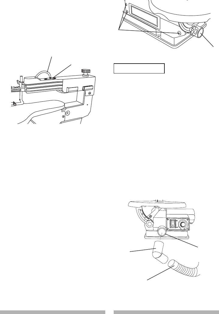
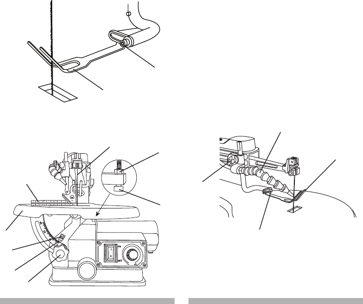
THE DUST BLOWER (FIG. D)
1. Locate the sawdust blower tubing (1).
2. Connect the PVC plastic end of the
tube to the bellows seat (2).
3. For best results, the dust blower
tube should be adjusted to direct air
at both the blade and the workpiece.
Fig. D
SAWDUST COLLECTION PORT (FIG.
E, F)
This scroll saw will accept a hose or
vacuum accessory (not provided)
to be connected to the sawdust
collection port (1) on the front of
base. If excessive sawdust buildup
occurs inside the base, use a wet/dry
vacuum cleaner or manually remove
sawdust by first unplugging the saw
from the power source, then removing
the three screws (2) on the left side
of saw holding the plate cover. After
cleaning all sawdust buildup, reattach
the plate and screws before restarting
the saw. This will keep your saw cutting
efficiently.
Fig. E
● To prevent fire hazard, clean and
remove sawdust from under the
saw frequently.
● To prevent sawdust build up inside
the saw housing, attach a vacuum
hose (3) to the sawdust collection
port (1) at the front of the scroll
saw. DO NOT operate the saw
with the hose in place unless the
vacuum is turned on.
NOTE: A 43-38 mm (1-11/16 in-1-1/2
in) dust port adapter (4) is provided for
your convenience.
Fig. F
1
2
2
1
1
4
3
WARNING
!
18 19
18 19
BLADE REMOVAL AND
INSTALLATION
PIN-END BLADE REMOVAL AND
INSTALLATION
To prevent personal injury, always
turn the saw OFF and disconnect the
plug from source before changing
blades or making adjustments.
Pin-end type blades are thicker for
stability and for faster assembly. These
blades are used whenever faster
cutting on a variety of materials and 3/4
in. thickness or greater are required.
Use whenever less precision or thicker
kerf cutting is acceptable.
NOTE: When installing pin-end blades,
the set screws located on the upper
and lower blade holders should not be
over or under tightened. The slot must
be slightly wider than the thickness of
the blade. After the blade is installed,
the blade tension mechanism will keep
the pin-end in place.
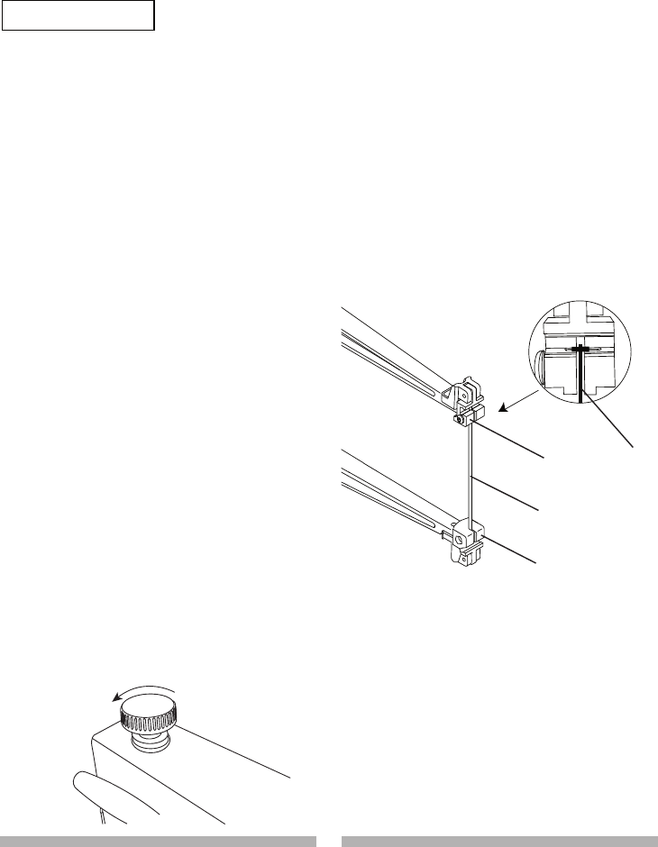
PIN-END BLADE REMOVAL (FIG. G,
H)
1. Loosen the tension on the blade
by turning the tension knob
counterclockwise. (Fig. G).
Fig. G
2. Remove the blade (2) from the
upper (3) and lower (4) blade holder
by pulling blade forward to release,
and lift the blade through the access
hole. (Fig. H)
NOTE:
● Apply slight downward pressure
on the upper arm when removing
the blade from the upper blade
holder.
● If the tension is still too tight to
remove blade, turn the tension
lever (Fig. G) counterclockwise
no more than one rotation. (Do
not over-loosen.)
Fig. H
2
3
4
2
WARNING
!
20 21
20 21
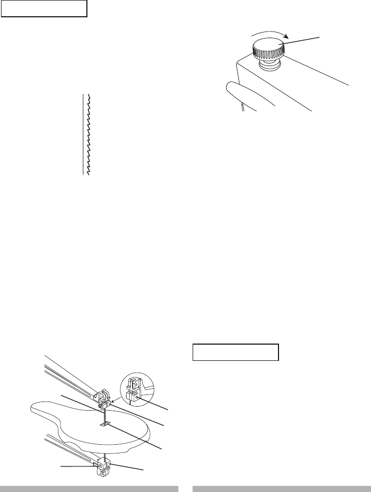
3. Tighten the tension on the blade by
turning the tension knob clockwise
(Fig. K). If the tension is too tight,
turn counterclockwise. If too loose,
turn the knob clockwise.
Fig. K
PLAIN-END BLADE REMOVAL AND
INSTALLATION
This scroll saw accepts 5-inch plain-
end or pin-end blades to cut a wide
variety of materials.
Plain-end type blades are
recommended whenever fine, accurate
and intricate work is being performed
on 3/4 in. or thinner material. It will take
slightly longer to assemble and tension
the blade, but you will also be able to
use finer blades for cutting a thinner
kerf.
To avoid injury from accidental
starting, always turn the switch OFF
and remove power cord plug from
power source before removing or
replacing the blade.
PIN-END BLADE INSTALLATION
(FIG. I, J, K)
NOTE: Do not tighten the set screw (1,
2) when using Pin-end blades. (Fig. J)
In order to avoid uncontrollable
lifting of the workpiece, the teeth
of the blade MUST ALWAYS point
downward. (Fig. I)
Fig. I
1. Install the blade (3) by inserting one
end of it through the access hole (4)
of throat plate in the table. Hook the
lower blade pin in the pin recess in
the lower blade holder (5) and then
the upper blade pin in the upper
blade holder (6). (Fig. J)
2. Check to see that the pins are
properly located in the upper (6) and
the lower (5) blade holders. (Fig. J)
Fig. J
1
6
3
4
5
2
7
WARNING
!
WARNING
!
20 21
20 21
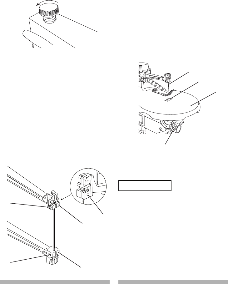
PLAIN-END BLADE REMOVAL
(FIG. L, M, N)
1. Loosen the tension on the blade
by turning the tension knob
counterclockwise. (Fig. L)
Fig. L
2. Loosen the upper blade holder (2) by
turning the blade holder set screw (3)
counterclockwise using the supplied
T-wrench. (Fig. M)
NOTE: The hex screw (4) on the left
side is used for fine adjustments and
is only adjusted if the blade is not
perpendicular to the table. You need
a 5 mm hex wrench for hex hex
screw (4).
Fig. M
3. Tilt the table to 0° and tighten the
table lock knob (7-Fig. N). Loosen
the lower blade holder lock screw
(5-Fig. M) under the table on the left
side of the lower blade holder (6-Fig.
M) with the supplied T-wrench by
turning counterclockwise.
4. Remove the blade (8) from the upper
and lower blade holders by pulling
forward and lifting the blade through
the access hole (9) in the table (10).
(Fig. N)
Fig. N
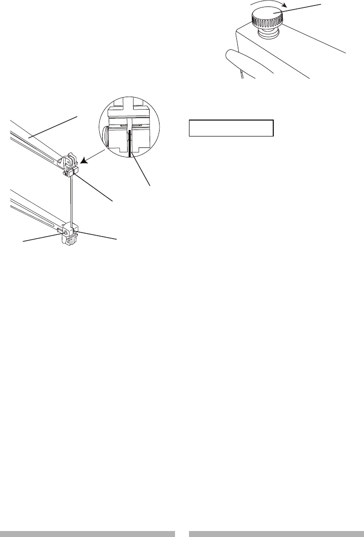
PLAIN-END BLADE INSTALLATION
(FIG. O, P)
In order to avoid uncontrollable
lifting of the workpiece, the teeth
of the blade MUST ALWAYS point
downward.
1. Install the new blade through the
access hole in the table with teeth
pointing down.
3
2
4
5
6
7
10
9
8
WARNING
!
22 23
22 23
2. Insert the new blade into the lower
blade holder slot (1), and then
tighten the lower blade holder set
screw (2). (Fig. O)
3. Tilt the table to the 0° bevel setting
and lock the table lock knob.
Fig. O
4. Insert the other end of the blade into
the upper blade holder slot (3-Fig.
O) and then tighten the tension knob
(5-Fig. P).
NOTE: Apply slight downward
pressure against the upper arm
(4-Fig. O) when installing the blade
into the upper blade holder.
5. Tighten the tension on the blade
by turning the tension knob (5)
clockwise. If the tension is too tight,
turn counterclockwise. If too loose,
turn the lever clockwise. Do not
make too tight or blade will easily
break in use. (Fig. P)
Fig. P
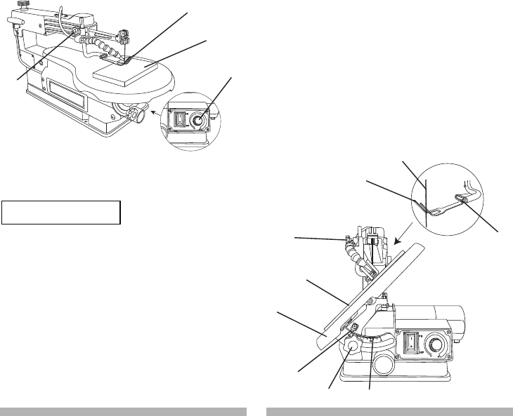
BEVEL STOP ADJUSTMENT
To avoid injury from accidental
starting, always turn the switch OFF
and unplug the scroll saw before
moving, replacing the blade or
making adjustments.
900 (00) Bevel Adjustment (Fig. Q, R)
1. Remove the blade guard foot (1) by
using the supplied T-wrench to turn
the hex screw (2) counterclockwise.
(Fig. Q)
2. Loosen the table lock knob (3)
and move the table (4) until it is
approximately at a right angle to the
blade (5).
3. Loosen the lock nut (6) and adjust
the adjusting screw (7) under the
table by turning counterclockwise.
4. Lower the adjusting screw by turning
clockwise.
5. Use a combination square (8) to
set the table exactly 900 (00) to the
blade. If there is space between the
square and blade, adjust the table
angle until the space is closed.
6. Lock the table lock knob (3) under
the table to prevent movement.
Raise the adjusting screw under
the tabel until the tip of the screw
touches the table.
1
2
3
4
3
5
WARNING
!
22 23
22 23
7. Tighten the lock nut (6).
8. When the blade is exactly 900
(00) to the table, loosen the bevel
indicator screw (9) using a Phillips
screwdriver.
9. Adjust the bevel indicator (10) to
the “0” mark on the bevel scale and
retighten the indicator screw (9).
10. Attach the blade guard foot (1)
using the T-wrench, so the foot
rests flat against the table and
tighten. (Fig. Q)
NOTE: Avoid setting the edge of the
table against the top of the motor,
which could cause noise when the saw
is running.
Fig. Q
Fig. R
BLADE GUARD FOOT ADJUSTMENT
(FIG. S)
NOTE: User must keep constant
downward pressure on workpiece when
cutting. The blade guard foot is not
designed to hold down the workpiece,
but is rather to help prevent the
workpiece from lifting up excessively.
When cutting at angles, the table guard
foot (1) should be adjusted so it is
parallel to the table and rests flat above
the workpiece.
1. To adjust, loosen the screw (2), tilt
the foot so it is parallel to table and
tighten the screw.
2. Loosen the blade guard foot lock
knob (3) to raise or lower the foot
until it rests slightly above the
workpiece. Tighten blade guard foot
lock knob.
NOTE: To remove the blade guard foot
(1), loosen the hex screw (2) by using
the supplied T-wrench to turn the screw
counterclockwise.
Fig. S
1
2
5
8
9
10
3
4
7
6 1
2
3
4

24 25
24 25
SAWDUST BLOWER (FIG. S)
The sawdust blower (4) should be
positioned to point to the blade and
workpiece to blow sawdust out of the
line-of-sight when cutting. It is not
designed to blow all of the sawdust off
the table, and will operate only when
the unit is turned on.
BLADE SELECTION (FIG. T)
To avoid injury from accidental
starting, always turn the switch OFF
and unplug the scroll saw before
moving, replacing the blade or
making adjustments.
This scroll saw accepts 5-inch length
blades with a wide variety of blade
thickness and widths. The type of
material and intricacies of cutting
operations (size of radius or curve)
will determine the number of teeth per
inch. As a general rule, always select
the narrowest blades for intricate
curve cutting and the widest blades
for straight and large curve cutting
operations.
The following table represents
suggestions for various materials.
When purchasing blades, refer to
the back of the package for the best
use of blades and speeds on various
materials.
10~37
9.5~48 9.5~33
Use this table as an example, but
practice and your own personal
preference will be the best selection
method.
NOTE: When using blades, sometimes
speeds must change to compensate
for smaller curves, radii or smaller
diameters. Thinner blades will have
more possibilities for blade deflection
when cutting angles which are not
perpendicular to the table. Read BASIC
SCROLL SAW OPERATION for more
suggestions.
NOTE: The blade must be installed
with the teeth pointing downward,
as shown in Fig. T, to prevent the
workpiece from being pulled upward by
the saw blade action.
Fig. T
WARNING
!

24 25
24 25
General Scroll Saw Blade Reference Guide
Tooth
Type
TPI
Application
Speed
Faster Slower
Standard 9.5 ~ 48 General cutting
Skip 9.5 ~ 33 Better chip removal. Smooth, splinterless finish
Double 10 ~ 37 Efficient chip removal. Clean edges
Reverse
9/5 ~ 28/21 Eliminates underside tearout. Smooth,
splinterless finish
Spiral 36 ~ 46 All direction cutting
1. Hard, thicker wood - Coarse TPI, slower speed.
2. Soft, thinner wood - Fine TPI, faster speed.
3. Plastic materials - Slower speed.
4. Please use the blades for the applications recommended by the blade
suppliers.
26 27
26 27
OVERLOAD BREAKER (FIG. U)
When the motor in overload during
operation, the overload breaker will
cause the motor to stop automatically
to prevent damage to the motor. Push
in the ON/OFF switch (2) to turn saw
OFF, after that push the ON/OFF
switch (2) to ON to start the saw.
Other way to restart the saw:
Disconnect the power supply firstly,
keep switch in ON position, then
connect the power supply, the motor
will start automatically.
Fig. U
RECOMMENDATIONS FOR CUTTING
1. When feeding the workpiece into
the blade do not force the leading
edge of the workpiece into the
blade because the blade will
deflect, reducing the accuracy
of cut and possibly breaking the
blade. Allow the saw to cut material
by guiding the workpiece into the
blade as it cuts.
2. The blade teeth cut material ONLY
on the down stroke.
3. You must guide the wood into the
blade slowly because the teeth of
the blade are very small and they
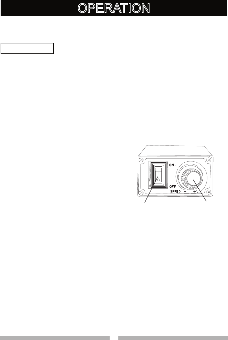
VARIABLE SPEED CONTROL AND
ON/OFF SWITCH
● For your own safety, always push
the switch “OFF” when the scroll
saw is not in use. Also, in the
case of power failure (all of your
lights go out) push the knob
“OFF”. Remove the plug from
the power source outlet to avoid
accidental starting.
● The variable speed control allows
greater versatility to cut a variety
of materials such as wood,
plastics, non-ferrous metals, etc.
Depending on the hardness and
thickness of material, the speed
should be reduced to allow
the blade teeth to remove cut
material from the kerf.
VARIABLE SPEED SWITCH (FIG. U)
1. Your saw is equipped with a
variable speed control knob (1).
The blade stroke rate may be
adjusted by simply rotating the
variable speed control knob (1).
2. Turn the control knob clockwise
the increase up to 1,600 strokes
per minute (SPM). Turn the control
knob counterclockwise to reduce,
down to 400 strokes per minute
(SPM).
ON/OFF SWITCH (FIG. U)
1. To turn power ON or OFF, push the
ON/OFF switch (2).
1
2
OPERATION
WARNING
!

26 27
26 27
11. This saw uses 5 in. long pin or plain
end type blades only.
12. Blades wear faster when cutting
plywood or particle board which
is very abrasive. Angle cutting in
hardwoods reduces blade tooth set
faster due to the blade deflection.
FREEHAND CUTTING (FIG. V)
To avoid injury from an accidental
start, make sure the switch is in
the OFF position and the plug is
not connected to the power source
outlet.
1. Lay out desired design, or secure
design to the workpiece (1).
2. Raise the blade guard foot (2) by
loosening the blade guard foot lock
knob (3).
3. Position the workpiece against the
blade and place the blade guard
foot slightly above the top surface
of the workpiece.
4. Secure the blade guard foot (2) by
tightening the blade guard foot lock
knob (3).
5. Remove the workpiece from the
blade prior to turning the scroll saw
ON. Set the variable speed control
knob (4) to the desired speed by
turning the control knob clockwise
or counterclockwise.
CAUTION: In order to avoid
uncontrollable lifting of the
workpiece and to reduce blade
breakage, do not turn saw ON
while the workpiece is against the
blade.
can only remove wood when they
are on the down stroke.
4. There is a learning curve for each
person who wants to use this
saw. During that period of time it
is expected that some blades will
break until you learn how to use
the saw and receive the greatest
benefit from the blades.
5. Best results are achieved when
cutting wood less than one inch
thick.
6. When cutting wood thicker than
one inch, the user must guide the
wood very slowly into the blade and
take extra care not to bend or twist
the blade while cutting in order to
maximize blade life.
7. Teeth on scroll saw blades wear out
and must be replaced frequently
for best cutting results. Scroll saw
blades generally stay sharp for 1/2
to 2 hours of cutting, depending on
material being cut.
8. To get accurate cuts, be prepared
to compensate for the blade’s
tendency to follow the wood grain
as you are cutting.
9. This scroll saw is intended to cut
wood or wood products. Plastics
and non-ferrous metals perform
well on scroll saws that have very
slow speed capability, and should
be lubricated with machine oil or
beeswax.
10. When choosing a blade to use
with your scroll saw, consider very
fine, narrow blades to scroll cut in
thin wood 1/4 in. thick or less. Use
wider blades for thicker materials
but this will reduce the ability to cut
tight curves.
WARNING
!
28 29
28 29
Left Bevel Cutting (Fig. W)
Bevel cuts up to 45 degrees to the left
are possible on this unit.
1. Lay out or secure design to
workpiece (1).
2. Move the blade guard foot (2) to the
highest position by loosening the
blade guard foot lock knob (3) and
retighten.
3. Tilt the table (4) to the desired angle
by loosening the table lock knob (5)
and move the table to the proper
angle, using the degree scale (6)
and the pointer (7).
4. Tighten the table lock knob (5).
5. Loosen the blade guard screw (8),
and tilt the blade guard to the same
angle as the table (4). Retighten the
blade guard screw.
6. Position the workpiece on the left
and right side of the blade (9). Lower
the blade guard foot slightly above
the surface by loosening the blade
guard foot lock knob (3).
7. Follow items 4-8 under FREEHAND
CUTTING OPERATION.
Fig. W
6
1
2
3
4
5
7
8
9
6. When turning the scroll saw ON,
position the workpiece against scrap
wood prior to touching the leading
edge of the workpiece against the
blade.
7. Slowly feed the workpiece into the
blade by guiding and pressing the
workpiece down against the table.
CAUTION: Do not force the leading
edge of the workpiece into the blade.
The blade will deflect, reducing
accuracy of cut, and may break.
8. When the cut is complete, move
the trailing edge of the workpiece
beyond the blade guard foot. Turn
the scroll saw OFF.
Fig. V
BEVEL CUTTING (FIG. W)
To avoid injury from an accidental
starting, make sure the switch is
in the OFF position and the plug is
not connected to the power source
outlet before moving, replacing the
blade or making adjustments.
3
2
1
4
WARNING
!
28 29
28 29
saw ON. Set the desired speed by
turning the control knob clockwise or
counterclockwise.
CAUTION: In order to avoid
uncontrollable lifting of the workpiece
and reduce blade breakage, do not
turn saw ON while the workpiece is
against the blade.
7. Position the workpiece against the
straight edge (4) prior to touching
the leading edge of the workpiece
against the blade (3).
8. Slowly feed the workpiece into the
blade, guiding the workpiece against
the straight edge and press the
workpiece down against the table
while cutting.
CAUTION: Do not force the leading
edge of the workpiece into the blade.
The blade will deflect, reducing
accuracy of cut and may break.
9. When the cut is complete, move
the trailing edge of the workpiece
beyond the blade guard foot. Turn
the scroll saw OFF.
NOTE: When cutting a narrow
workpiece use push sticks.
Fig. X
2
3
1
5
4
RIP OR STRAIGHT LINE CUTTING
(FIG. X)
To avoid injury from an accidental
starting, make sure the switch is
in the OFF position and the plug is
not connected to the power source
outlet before moving, replacing the
blade or making adjustments.
Tools Needed (Not Included)
1. Raise the blade guard foot (1) by
loosening the blade guard foot lock
knob (2) on the right side of the
upper arm. Measure from the tip of
the blade (3) to the desired distance.
Position the straight edge (4) parallel
to the blade at that distance.
2. Clamp the straight edge (4) to the
table (5).
3. Recheck your measurements, using
the workpiece to be cut, and make
sure the scrap wood is secure.
4. Position the workpiece against the
blade and place the blade guard foot
(1) slightly above the top surface of
the workpiece.
5. Secure the blade guard foot in place
by tightening the height adjustment
knob.
6. Remove the workpiece from the
blade prior to turning the scroll
QUANTITY DESCRIPTION
2 Small C-clamps
1 Ruler or measuring tape
1
12-inch straight scrap
of wood (Thickness to
match workpiece)
WARNING
!
30 31
30 31
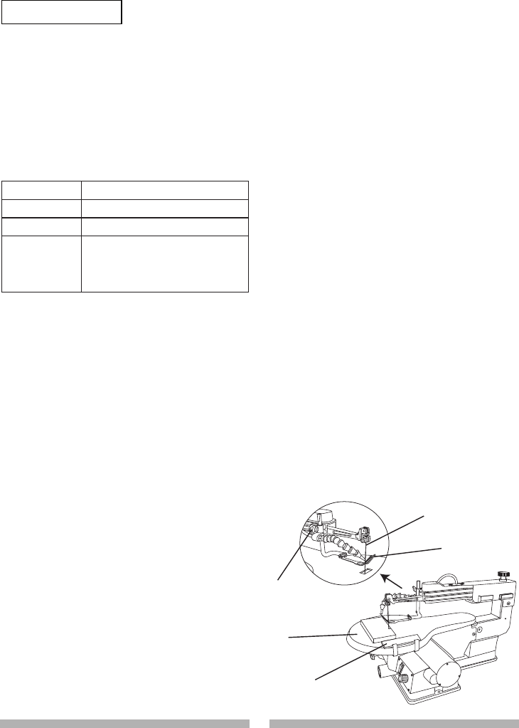
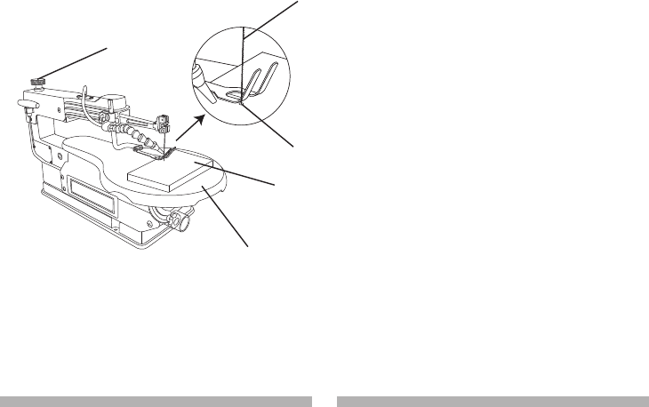
INTERIOR CUTTING (FIG. Y)
1. Lay out the design on the workpiece
(1). Drill a 1/4 in. hole (4) in the
workpiece .
2. Remove the blade by turning the
tension knob (2) counterclockwise.
Refer to BLADE REMOVAL AND
INSTALLATION.
3. Place the workpiece on the saw
table with the workpiece hole (4)
over the access hole in the table (5).
4. Install the blade (3) through the hole
in the workpiece and tighten the
tension knob (2).
5. Follow the process, items 3-8,
under FREEHAND CUTTING
OPERATIONS.
6. When finished making the interior
scroll cuts simply turn the scroll
saw OFF, remove the blade from
the blade holder and remove the
workpiece from the table.
Fig. Y 3
4
5
1
2
30 31
30 31
For your own safety, turn the switch
OFF and remove the plug from the
power source before maintaining
your saw.
GENERAL
An occasional coat of paste wax on the
work table will allow the wood being
cut to glide smoothly across the work
surface.
MOTOR
1. If the power cord is worn, cut
or damaged in any way, have it
replaced immediately by authorized
electrician.
2. Do not attempt to oil the motor
bearings or service the motor
internal parts.
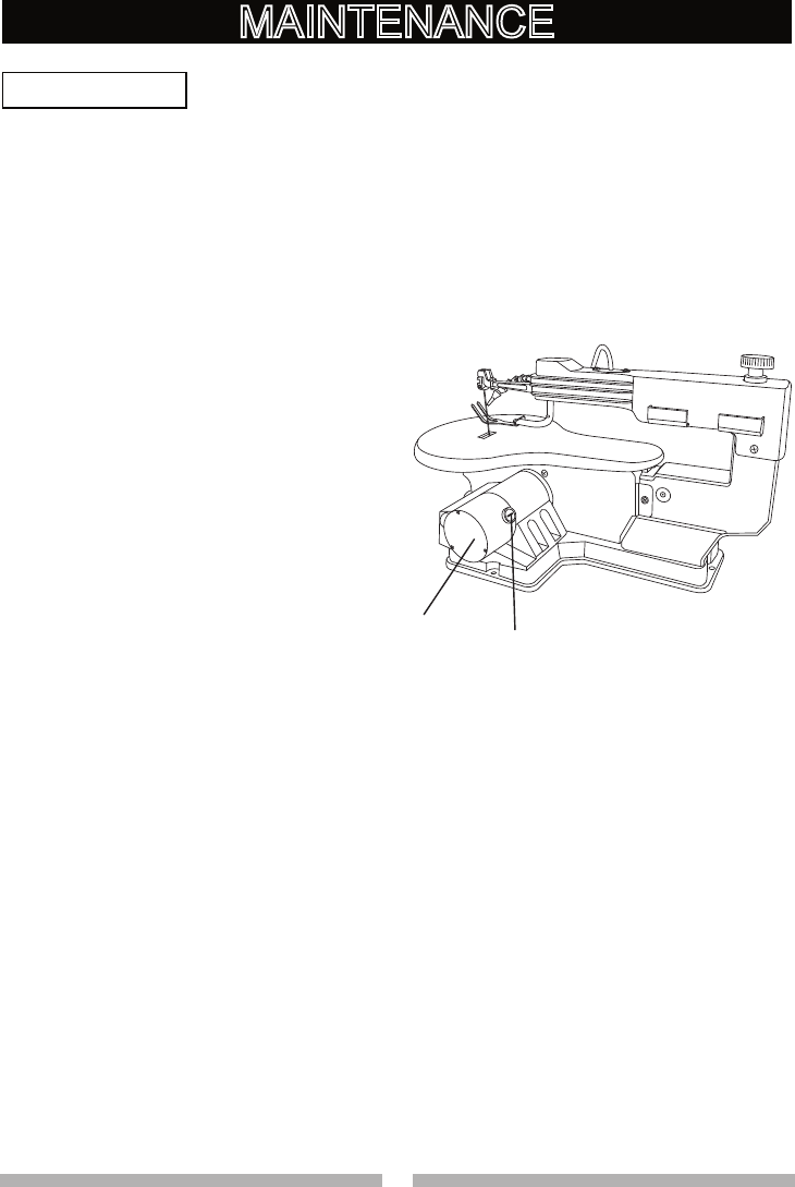
REPLACING CARBON BRUSHES
(FIG. Z)
Replace both carbon brushes when
either has less than 1/4 in. length of
carbon remaining, or if the spring or
wire is damaged or burned. To inspect
or replace brushes, first unplug the
saw. Then remove the black plastic
cap (1) on the side of the motor (2).
Carefully remove the spring-loaded
cap. Then pull out the brush and
replace. Replace for the other side. To
reassemble reverse the procedure. The
ears on the metal end of the assembly
go in the same hole the carbon part fits
21
MAINTENANCE
into. Tighten the cap snugly, but do not
overtighten.
NOTE: When reinstalling the same
brushes, put them back in the way they
came out. This will avoid a break-in
period that reduces motor performance
and increases wear.
Fig. Z
WARNING
!

32 33
32 33
To avoid injury from accidental starting, always turn switch OFF and unplug
the tool before moving, replacing the blade or making adjustments.
PROBLEM PROBLEM CAUSE REMEDY SUGGESTED
Breaking blades 1. Wrong tension.
2. Overworking blades.
3. Wrong blade
application.
4. Twisting blade in wood.
1. Adjust blade tension. See BLADE
REMOVAL AND INSTALLATION
section.
2. Reduce feed rate. See BLADE
REMOVAL AND INSTALLATION
section.
3. Use narrow blade. See BLADE
SELECTION section.
4. Avoid side pressure on blade.
See BLADE REMOVAL AND
INSTALLATION section.
Motor will not
run.
1. Defective cord or plug.
2. Defective motor.
3. Blown overload
breaker.
1. Replace defective parts
before using saw again. See
ELECTRICAL SPECIFICATIONS
AND SAFETY section.
2. Call Service Center. Any attempt
to repair this motor may create a
HAZARD unless the repair is done
by a qualified technician.
3. Restart the saw. See OVERLOAD
BREAKER section.
Excessive
vibration.
NOTE: There will
always be some
vibration present
when the saw is
running because
of motor
operation.
1. Improper mounting of
saw.
2. Unsuitable mounting
surface.
3. Loose table or table
resting against motor.
4. Loose motor mounting.
1. See mounting instructions in
this manual for proper mounting
technique.
2. The heavier your workbench is,
the less vibration will occur. A
plywood workbench will not be as
good a work surface as the same
size solid lumber.
3. Tighten the table lock knob.
4. Tighten motor mounting screw.
Blade run out.
Blade not in line
with arm motion.
1. Blade holders not
aligned.
1. Loosen blade holder lock screw
holding blade holder to arms.
Adjust position of blade holders.
Retighten blade holder lock screw.
See BLADE REMOVAL AND
INSTALLATION section.
TROUBLESHOOTING GUIDE
WARNING
!

32 33
32 33
NOTE

34 35
34 35
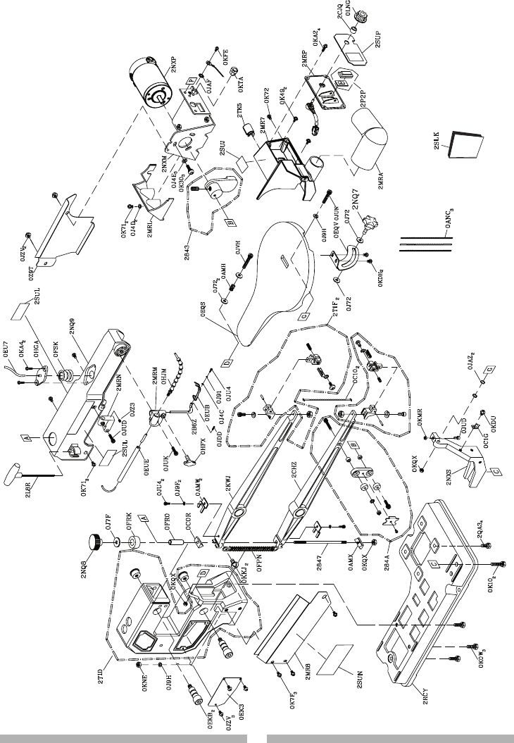
PARTS LIST
16 in. VARIABLE SPEED SCROLL SAW MODEL NO. 137.216020
When servicing use only CRAFTSMAN replacement parts. Use of any other
parts many create a HAZARD or cause product damage. Any attempt to
repair or replace electrical parts on this Scroll Saw may create a HAZARD
unless repair is done by a qualified service technician. Repair service is
available at your nearest Sears Service Center.
PARTS LIST FOR SAW SCHEMATIC
I.D. NO Description Size Qty I.D. NO Description Size Qty
2843 ECCENTRIC ASS’Y 1 0K71 CR. RE. TRUSS HD. SCREW M5*0.8-8 5
2847 LINGAGE BAR 1 0K72 CR. RE. TRUSS HD. SCREW M5*0.8-12 1
0AMH COMPRESSION SPRING 1 0K7F CR. RE. ROUND WASHER HD. SCREW M5*0.8-8 3
0AMW SET PLATE 2 0KA2 CR. RE. PAN HD. TAPPING SCREW M4*16-8 4
0AMX CLAMP BOLSTER 1 0KA4 CR. RE. PAN HD. TAPPING SCREW M4*16-16 2
0ANC BLADE 3 0KDH CR. RE. PAN HD. SCREW M5*0.8-8 2
0C0R CLAMP BOLSTER 1 0KDU CR. RE. PAN HD. SCREW M6*1.0-12 1
0C10 BLADE 2 0KFE CR. RE. PAN HD. SCREW M5*0.8-6 1
0C1G NEEDLE POINTER 1 0KKJ CR. RE. PAN HD. ROUND NECK SCREW M4*0.7-12 2
0EK3 CAUTION LABEL 1 0KMR HEX. NUT M5*0.8 T=4 1
0EKB HEX. SOC. HD. CAP BOLT 2 0KNE HEX. NUT M6*1.0 T=5 1
0EQS TABLE #AW 1 0KQX NUT M6*1.0 T=6 3
0EQV BRACKET-TILT 1 0KTA STRAIN RELIEF 1
0EU7 PVC HOSE 1 0LNG ON/OFF SPEED DIAL 1
0EUB BLADE GUARD 1 0Z9T SAFE COVER 1
0EUE SUPPORT ROD 1 284A BEARING SEAT ASS’Y 1
0FPN EXTENSION SPRING 1 2B6Z HOLD DOWN ROD 1
0FR0 SPACER 1 2CHZ BOTTOM ARM ROCKER ASS’Y #06 1
0FRK BUSH 1 2CJQ COLLAR-STOP 1
0FSK BELLOW 1 2KWJ UPPER ARM ROCKER ASS’Y #06 1
0HFX BOLT CLAMP 1 2L8R T-WRENCH 3 mm 1
0HGA BELLOWS SEAT 1 2MR7 SWITCH BOX 1
0HJM AIR DUCT ASS’Y 1 2MR8 PLATE COVER 1
0J4C FLAT WASHER φ4*8-1 1 2MRA DUST PORT ADAPTER 1
0J4D FLAT WASHER φ5*10-1 2 2MRL MOTOR REAR COVER 1
0J4E FLAT WASHER φ6*13-1 3 2MRM PLUNGER HOUSING 1
0J72 FLAT WASHER 1/4*5/8-1/16 4 2MRN PLUNGER HOUSING 1
0J7F FLAT WASHER 5/16*7/8-5/64 1 2MRP CONTROLLER PLATE 1
0J91 SPRING WASHER φ4 1 2NQ7 KNOB 1
0J9F SPRING WASHER φ5/32 2 2NQ8 HANDLE 1
0J9H SPRING WASHER φ1/4” 2 2NQ9 ROCKER ARM COVER 1
0JAF EXTERNAL TOOTH LOCK WASHER φ5 1 2NXM MOTOR BRACKET 1
0JAZ WAVE WASHER WW-6 2 2NXP MOTOR 1
0JDD SPRING PIN 1 2NXS SUPPORT #06 1
0JU4 HEX. SOC. HD. CAP BOLT M4*0.7-10 3 2P2P ROCK SWITCH ASS’Y 1
0JUD HEX. SOC. HD. CAP BOLT M5*0.8-20 2 2QA3 HEX. HD. SCREW AND WASHER M6*1.0-25 4
0JUK HEX. SOC. HD. CAP BOLT M6*1.0-16 1 2RCY BASE #AW 1
0JUN HEX. SOC. HD. CAP BOLT M6*1.0-30 1 2SLK OWNER’S MANUAL ASS’Y 1
0JVH HEX. SOC. HD. CAP BOLT M6*1.0-35 1 2SUJ CAUTION LABEL 1
0JZ3 HEX. SOC. SET SCREW M6*1.0-6 1 2SUL TRADE-MARK LABEL 2
0JZV HEX. SOC. TRUSS HD. SCREW M5*0.8-10 5 2SUN WARNING LABEL 1
0K0W HEX. HD. SCREW AND WASHER M6*1.0-25 3 2SUP CAUTION LABEL 1
0K10 HEX. HD. SCREW AND WASHER M8*1.25-30 2 2T1D BODY ASS’Y 1
0K30 HEX. SOC. TRUSS HEAD & WASHER M6*1.0-16 3 2T1F HOLDER BLADE ASS’Y 2
0K49 CR. RE. PAN HD. SCREW & WASHER M5*0.8-10 2 2TK5 CABLE COVER 1
WARNING
!
34 35
34 35
16 in. VARIABLE SPEED SCROLL SAW MODEL NO. 137.216020
SCHEMATIC
OPERATOR’S
MANUAL

36 36
Your Home
For expert troubleshooting and home solutions advice:
www.managemyhome.com
For repair – in your home – of all major brand appliances,
lawn and garden equipment, or heating and cooling systems,
no matter who made it, no matter who sold it!
For the replacement parts, accessories and
owner’s manuals that you need to do-it-yourself.
For Sears professional installation of home appliances
and items like garage door openers and water heaters.
1-800-4-MY-HOME (1-800-469-4663)
Call anytime, day or night (U.S.A. and Canada)
www.sears.com www.sears.ca
Our Home
For repair of carry-in items like vacuums, lawn equipment,
and electronics, call anytime for the location of your nearest
Sears Parts & Repair Service Center
1-800-488-1222 (U.S.A.) 1-800-469-4663 (Canada)
www.sears.com www.sears.ca
To purchase a protection agreement on a product serviced by Sears:
1-800-827-6655 (U.S.A.) 1-800-361-6665 (Canada)
manage
my home
Get it fixed, at your home or ours!
Para pedir servicio de reparación
a domicilio, y para ordenar piezas:
1-888-SU-HOGAR
(1-888-784-6427)
Au Canada pour service en français:
1-800-LE-FOYERMC
(1-800-533-6937)
www.sears.ca
® Registered Trademark / TM Trademark / SM Service Mark of Sears Brands, LLC
® Marca Registrada / TM Marca de Fábrica / SM Marca de Servicio de Sears Brands, LLC
MC Marque de commerce / MD Marque déposée de Sears Brands, LLC © Sears Brands, LLC
R
R
