Craftsman 247 881731 Operators Manual ManualsLib Makes It Easy To Find Manuals Online!
2014-12-12
: Craftsman Craftsman-247-881731-Operators-Manual-119531 craftsman-247-881731-operators-manual-119531 craftsman pdf
Open the PDF directly: View PDF ![]() .
.
Page Count: 47
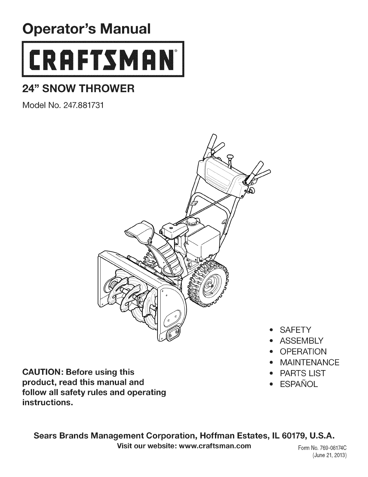
Operator's Manual
CRRFr MRN
24" SNOW THROWER
Model No. 247.881731
CAUTION" Before using this
product, read this manual and
follow all safety rules and operating
instructions.
,, SAFETY
o ASSEMBLY
OPERATION
MAINTENANCE
PARTS LIST
o ESPANOL
Sears Brands Management Corporation, Hoffman Estates, IL 60179, U.S.A.
Visit our website: www.craftsman.com FormI/o 769-081740
(June21,2013)
WarrantyStatement.............................. Page2
SafeOperationPractices...................... Pages3-6
Assembly.................................... Pages8-11
Operation.................................. Pages12-15
Service&Maintenance...................... Pages16-22
Off-SeasonStorage............................. Page23
Troubleshooting............................... Page24
PartsList................................... Pages26-43
RepairProtectionAgreement................... Page46
Espa_ol......................................... Page47
CRAFTSMANTWOYEARFULLWARRANTY
FORTWOYEARSfromthedateof purchase,thisproductiswarrantedagainstanydefectsinmaterialorworkmanship.Defectiveproductwill receivefree
repairorfreereplacementif repairisunavailable.
ADDITIONALLIFETIMELIMITEDWARRANTYon UPPERand LOWERCHUTE
FORASLONGASITISUSEDbytheoriginalownerafterthesecondyearfromthedateofpurchase,theupperandlowerchuteofthissnowthrowerare
warrantedagainstanydefectsinmaterialorworkmanshipasverifiedbyaSearsauthorizedserviceprovider.Withproofofpurchase,youwill receiveanew
chutefreeofcharge.Youareresponsiblefor thelaborcostofinstallationandanycostincurredto verifythedefect.
Forwarrantycoveragedetailsto obtainrepairorreplacement,visitthewebsite:www.craftsman.com
ThiswarrantycoversONLYdefectsinmaterialandworkmanship.WarrantycoveragedoesNOTinclude:
• Expendableitemsthatcanwearoutfromnormalusewithinthewarrantyperiod,includingbutnotlimitedto augers,augerpaddles,drift cutters,skid
shoes,shaveplate,shearpins,sparkplug,aircleaner,belts,andoilfilter.
• Standardmaintenanceservicing,oilchanges,ortune-ups.
•Tirereplacementorrepaircausedbypuncturesfromoutsideobjects,suchasnails,thorns,stumps,orglass.
•Tireorwheelreplacementorrepairresultingfromnormalwear,accident,orimproperoperationormaintenance.
• Repairsnecessarybecauseofoperatorabuse,includingbutnot limitedto damagecausedbyover-speedingtheengine,orfromimpactingobjectsthat
bendtheframe,augershaft,etc.
• Repairsnecessarybecauseofoperatornegligence,includingbutnot limitedto,electricalandmechanicaldamagecausedbyimproperstorage,failureto
usethepropergradeandamountofengineoil,orfailureto maintaintheequipmentaccordingto theinstructionscontainedinthe operator'smanual.
• Engine(fuelsystem)cleaningorrepairscausedbyfueldeterminedto becontaminatedoroxidized(stale).Ingeneral,fuelshouldbeusedwithin30days
ofitspurchasedate.
• Normaldeteriorationandwearoftheexteriorfinishes,orproductlabelreplacement.
Thiswarrantyisvoidif thisproductiseverusedwhileprovidingcommercialservicesorif rentedto anotherperson.
Thiswarrantygivesyouspecificlegalrights,andyoumayalsohaveotherrightswhichvaryfromstateto state.
SearsBrandsManagementCorporation,NoffmanEstates,IL60179
Engine Oil: 5W-30
Fuel: Unleaded Gasoline
Engine: MTD
Model Number
Serial Number
Date of Purchase
Record the model number, serial number,
and date of purchase above.
© Sears Brands, LLC 2
Thissymbolpointsout importantsafety instructionswhich, ifnot
followed, couldendangerthe personalsafetyand/or property of
yourselfand others.Readandfollow all instructions inthis manual
beforeattempting to operatethis machine.Failureto complywith these
instructionsmayresultinpersonalinjury.Whenyou seethis symbol, HEED
ITSWARNING!
CALIFORNIA PROPOSITION 65
EngineExhaust,someof its constituents,and certain vehiclecomponents
containor emit chemicalsknownto Stateof Californiato causecancerand
birth defectsorother reproductiveharm.
Thismachinewasbuilt to beoperatedaccordingto thesafeoperation
practicesinthis manual.Aswith anytype of powerequipment,
carelessnessorerroronthe part of the operatorcanresultinseriousinjury.
Thismachineiscapableof amputating fingers, hands,toesandfeet and
throwingdebris.Failureto observethefollowing safety instructionscould
resultinseriousinjuryor death.
Your Responsibility--Restrict theuseof this powermachineto
personswhoread,understandandfollow thewarningsand instructionsin
this manualandonthe machine.
SAVETHESEINSTRUCTIONS!
TRAINING
Read,understand,andfollowall instructionsonthemachineandinthe
manual(s)beforeattemptingto assembleandoperate.Failureto dosocan
resultinseriousinjurytotheoperatorand/orbystanders.Keepthis manual
inasafeplaceforfutureandregularreferenceandfororderingreplacement
parts.
Befamiliarwith all controlsandtheir properoperation.Knowhowto stop
themachineanddisengagethemquickly.
Neverallowchildrenunder14yearsof ageto operatethis machine.Children
14andovershouldreadandunderstandtheinstructionsandsafeoperation
practicesinthis manualandonthemachineandbetrainedandsupervised
byanadult.
Neverallowadultsto operatethismachinewithout properinstruction.
Thrownobjectscancauseseriouspersonalinjury.Planyoursnow-throwing
patternto avoiddischargeof materialtowardroads,bystandersandthelike.
Keepbystanders,petsandchildrenat least75feetfromthemachinewhileit
isin operation.Stopmachineif anyoneentersthearea.
Exercisecautionto avoidslippingorfalling,especiallywhenoperatingin
reverse.
PREPARATION
Thoroughlyinspecttheareawheretheequipmentisto beused.Removeall
doormats,newspapers,sleds,boards,wiresandotherforeignobjects,which
couldbetrippedoverorthrownbytheauger/impeller.
Alwayswearsafetyglassesoreyeshieldsduringoperationandwhile
performinganadjustmentor repairto protectyoureyes.Thrownobjects
whichricochetcancauseseriousinjuryto theeyes.
Donotoperatewithout wearingadequatewinteroutergarments.Donot
wearjewelry,longscarvesorotherlooseclothing,whichcouldbecome
entangledinmovingparts.Wearfootwearwhichwill improvefootingon
slipperysurfaces.
Usea groundedthree-wireextensioncordandreceptacleforallmachines
with electricstartengines.
Disengageallcontrolleversbeforestartingtheengine.
Adjustcollectorhousingheightto cleargravelorcrushedrocksurfaces.
Neverattemptto makeanyadjustmentswhileengineisrunning,except
wherespecificallyrecommendedintheoperator'smanual.
Letengineandmachineadjustto outdoortemperaturebeforestartingto
clearsnow.
Safe Handling of Gasoline:
Toavoidpersonalinjuryor property damageuseextremecareinhandling
gasoline.Gasolineisextremely flammableandthe vaporsareexplosive.
Seriouspersonalinjurycan occurwhengasolineis spilledonyourselforyour
clotheswhichcanignite. Washyour skinandchangeclothesimmediately.
Useonlyanapprovedgasolinecontainer.
Neverfill containersinsidea vehicleorona truckortrailerbedwitha plastic
liner.Alwaysplacecontainersonthegroundawayfromyourvehiclebefore
filling.
Whenpractical,removegas-poweredequipmentfromthetruckor
trailerandrefuelit ontheground.Ifthisisnotpossible,thenrefuelsuch
equipmentonatrailerwith aportablecontainer,ratherthanfromagasoline
dispensernozzle.
Keepthenozzleincontactwith therimofthefuel tankorcontaineropening
at alltimesuntil fuelingiscomplete.Donotusea nozzlelock-opendevice.
Extinguishall cigarettes,cigars,pipesandothersourcesof ignition.
Neverfuelmachineindoors.
Neverremovegascaporaddfuelwhiletheengineishotorrunning.Allow
engineto coolat leasttwo minutesbeforerefueling.
Neveroverfill fueltank.Filltankto nomorethan1/2inchbelowbottomof
filler neckto allowspacefor fuelexpansion.
Replacegasolinecapandtightensecurely.
Ifgasolineisspilled,wipeit offthe engineandequipment.Moveunitto
anotherarea.Wait.5minutesbeforestartingtheengine.
Toreducefirehazards,keepmachinefreeofgrass,leaves,orotherdebris
build-up.Cleanupoilorfuelspillageandremoveanyfuelsoakeddebris.
Neverstorethemachineorfuelcontainerinsidewherethereisanopen
flame,sparkorpilotlightasonawaterheater,spaceheater,furnace,clothes
dryerorothergasappliances.
OPERATION
Donotputhandsorfeetnearrotatingparts,intheauger/impellerhousing
orchuteassembly.Contactwith therotatingpartscanamputatehandsand
feet.
Theauger/impellercontrolleverisasafetydevice.Neverbypassits
operation.Doingsomakesthemachineunsafeandmaycausepersonal
injury.
Thecontrolleversmustoperateeasilyin bothdirectionsandautomatically
returnto thedisengagedpositionwhenreleased.
Neveroperatewith amissingordamagedchuteassembly.Keepallsafety
devicesinplaceandworking.
Neverrunanengineindoorsor inapoorlyventilatedarea.Engineexhaust
containscarbonmonoxide,anodorlessanddeadlygas.
Donotoperatemachinewhileundertheinfluenceof alcoholordrugs.
Mufflerandenginebecomehotandcancauseaburn.Donottouch.Keep
childrenaway.
Exerciseextremecautionwhenoperatingonorcrossinggravelsurfaces.Stay
alertforhiddenhazardsortraffic.
Exercisecautionwhenchangingdirectionandwhileoperatingonslopes.Do
notoperateon steepslopes.
Planyoursnow-throwingpatternto avoiddischargetowardswindows,
walls,carsetc.Thus,avoidingpossiblepropertydamageorpersonalinjury
causedbyaricochet.
Neverdirectdischargeat children,bystandersandpetsor allowanyonein
frontof themachine.
Donotoverloadmachinecapacitybyattemptingto clearsnowat toofastof
arate.
Neveroperatethismachinewithoutgoodvisibilityorlight.Alwaysbesureof
yourfootingandkeepafirm holdonthehandles.Walk,neverrun.
Disengagepowerto theauger/impellerwhentransportingornotin use.
Neveroperatemachineat hightransportspeedsonslipperysurfaces.Look
downandbehindandusecarewhenbackingup.
If the machineshouldstartto vibrateabnormally,stoptheengine,
disconnectthesparkplugwire andgrounditagainstthe engine.Inspect
thoroughlyfordamage.Repairanydamagebeforestartingandoperating.
Disengageallcontrolleversandstopenginebeforeyouleavetheoperating
position(behindthehandles).Waituntil theauger/impellercomesto
acompletestopbeforeuncloggingthechuteassembly,makingany
adjustments,orinspections.
Neverputyourhandin thedischargeorcollectoropenings.Donotunclog
chuteassemblywhileengineis running.Shutoff engineandremainbehind
handlesuntil allmovingpartshavestoppedbeforeunclogging.
Useonlyattachmentsandaccessoriesapprovedbythemanufacturer(e.g.
wheelweights,tirechains,cabsetc.).
Whenstartingengine,pull cordslowlyuntil resistanceisfelt,thenpull
rapidly.Rapidretractionofstartercord(kickback)will pullhandandarm
towardenginefasterthanyoucanletgo.Brokenbones,fractures,bruisesor
sprainscouldresult.
Ifsituationsoccurwhicharenotcoveredinthismanual,usecareandgood
judgment.
CLEARING A CLOGGED DISCHARGE CHUTE
Handcontactwith therotatingimpellerinsidethedischargechuteisthemost
commoncauseof injuryassociatedwith snowthrowers.Neveruseyourhandto
cleanoutthedischargechute.
Toclearthechute:
a. SHUTTHEENGINEOFF!
b. Wait10secondsto besuretheimpellerbladeshavestopped
rotating.
c. Alwaysuseaclean-outtool,notyourhands.
MAINTENANCE &STORAGE
Nevertamperwith safetydevices.Checktheirproperoperationregularly.
Referto themaintenanceandadjustmentsectionsof thismanual.
Beforecleaning,repairing,orinspectingmachinedisengageallcontrol
leversandstoptheengine.Waituntil theauger/impellercometo acomplete
stop.Disconnectthesparkplugwire andgroundagainsttheengineto
preventunintendedstarting.
Checkboltsandscrewsforpropertightnessat frequentintervalsto keepthe
machineinsafeworkingcondition.Also,visuallyinspectmachineforany
damage.
Donotchangetheenginegovernorsettingorover-speedtheengine.The
governorcontrolsthemaximumsafeoperatingspeedof the engine.
Snowthrowershaveplatesandskidshoesaresubjectto wearanddamage.
Foryoursafetyprotection,frequentlycheckallcomponentsandreplace
with originalequipmentmanufacturer's(OEM)partsonlyaslistedinthe
Partspagesofthisoperator'smanual.Useof partswhichdonot meetthe
originalequipmentspecificationsmayleadto improperperformanceand
compromisesafety!
Checkcontrolleversperiodicallyto verifytheyengageanddisengage
properlyandadjust,if necessary.Referto theadjustmentsectioninthis
operator'smanualfor instructions.
Maintainorreplacesafetyandinstructionlabels,asnecessary.
Observeproperdisposallawsandregulationsforgas,oil,etc.to protectthe
environment.
Priorto storing,runmachineafewminutesto clearsnowfrommachineand
preventfreezeupof auger/impeller.
Neverstorethemachineorfuelcontainerinsidewherethereisanopen
flame,sparkorpilot light suchasa waterheater,furnace,clothesdryeretc.
Alwaysreferto theoperator'smanualforproperinstructionsonoff-season
storage.
4
Checkfuelline,tank,cap,andfittingsfrequentlyfor cracksor leaks.Replace
if necessary.
Donotcrankenginewith sparkplugremoved.
Accordingto theConsumerProductsSafetyCommission(CPSC)andthe
U.S.EnvironmentalProtectionAgency(EPA),thisproducthasan Average
Useful Lifeof seven(7)years,or60 hoursofoperation.Attheendof
theAverage Useful Life havethemachineinspectedannuallybyan
authorizedservicedealerto ensurethat all mechanicalandsafetysystems
areworkingproperlyandnotwornexcessively.Failureto dosocanresultin
accidents,injuriesordeath.
DO NOT MODIFY ENGINE
Toavoidseriousinjuryordeath,donotmodifyengineinanyway. Tampering
with the governorsetting canleadto arunawayengineandcauseit to
operateat unsafespeeds.Nevertamper with factorysetting of engine
governor.
NOTICE REGARDING EMiSSiONS
Engineswhich are certifiedto complywith Californiaandfederal EPA
emissionregulationsfor SORE(SmallOff RoadEquipment)arecertified
to operateon regularunleadedgasoline,and mayincludethe following
emissioncontrolsystems:EngineModification (EM),OxidizingCatalyst(0C),
SecondaryAir injection(SAI)andThreeWayCatalyst(TWC)ifsoequipped.
SPARK ARRESTOR
e
Thismachineisequippedwith an internalcombustionengineandshould
not beusedonornearanyunimprovedforest-covered,brushcoveredor
grass-coveredland unlessthe engine'sexhaustsystemisequippedwith a
sparkarrestormeeting applicable localorstate laws (if any).
Ira sparkarrestoris used,it shouldbemaintainedin effective working order
bythe operator.In theState of Californiathe aboveisrequired bylaw (Section
4442of the CaliforniaPublicResourcesCode).Otherstates mayhavesimilar
laws.Federallawsapplyonfederal lands.
Asparkarrestorfor the muffler is availablethroughyour nearestSearsParts
andRepairServiceCenter.
SAFETY SYMBOLS
Thispage depicts and describes safety symbols that may appear on this product. Read, understand, and follow all instructions on the machine before
attempting to assemble and operate.
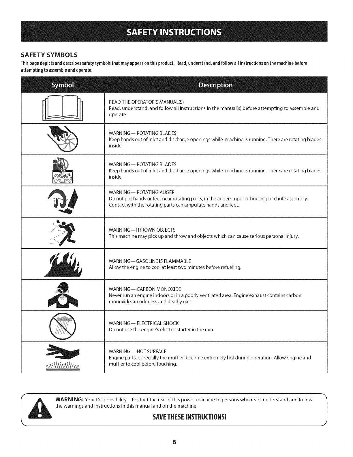
READ THE OPERATOR'S MANUAL(S)
Read, understand, and follow all instructions in the manual(s) before attempting to assemble and
operate
WARNING-- ROTATING BLADES
Keep hands out of inlet and discharge openings while machine is running. There are rotating blades
inside
WARNING-- ROTATING BLADES
Keep hands out of inlet and discharge openings while machine is running. There are rotating blades
inside
WARNING-- ROTATING AUGER
Do not put hands or feet near rotating parts, in the auger/impeller housing or chute assembly.
Contact with the rotating parts can amputate hands and feet.
WARNING--THROWN OBJECTS
This machine may pick up and throw and objects which can cause serious personal injury.
WARNING--GASOLINE IS FLAMMABLE
Allow the engine to cool at least two minutes before refueling.
WARNING-- CARBON MONOXIDE
Never run an engine indoors or in a poorly ventilated area. Engine exhaust contains carbon
monoxide, an odorless and deadly gas.
WARNING-- ELECTRICAL SHOCK
Do not use the engine's electric starter in the rain
WARNING-- HOT SURFACE
Engine parts, especially the muffler, become extremely hot during operation. Allow engine and
muffler to cool before touching.
WARNING: Your Responsibility--Restrict the use of this power machine to persons who read, understand and follow
the warnings and instructions in this manual and on the machine.
SAVETHESEiNSTRUCTIONS!
6

This page left intentionallyblank.
7
NOTE:Referencesto rightor left sideofthesnowthroweraredeterminedfrom
behindtheunitin theoperatingposition(standingdirectlybehindthesnow
thrower,facingthehandlepanel).
Removing FromCarton
1. Cutthe cornersof thecartonandlaythesidesflat on theground.Remove
anddiscardallpackinginserts.
2. Movethe snowthroweroutof thecarton.
3. Makecertainthecartonhasbeencompletelyemptiedbeforediscardingit.
Assembly
1.
2.
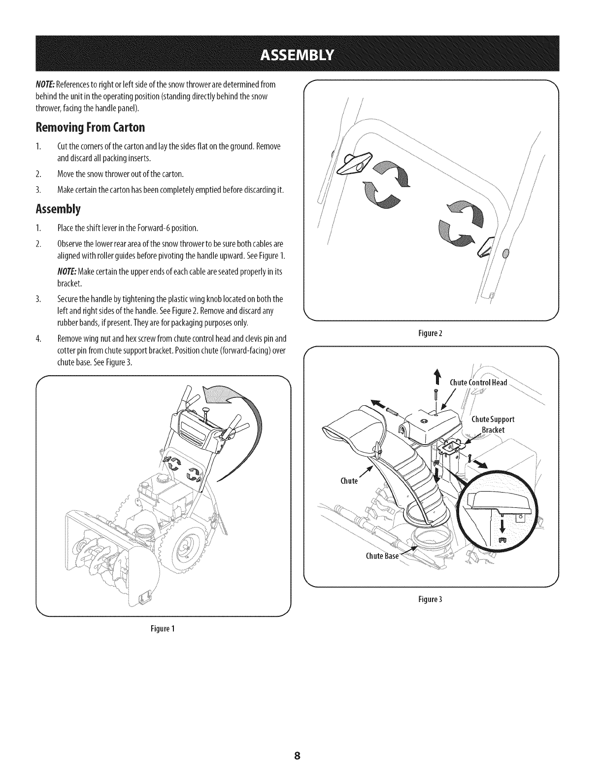
Placetheshift leverintheForward-6position.
Observethelowerrearareaof thesnowthrowerto besurebothcablesare
alignedwith rollerguidesbeforepivotingthehandleupward.SeeFigure1.
NOTE:Makecertaintheupperendsof eachcableareseatedproperlyin its
bracket.
3. Securethehandlebytighteningtheplasticwingknoblocatedonboththe
left andrightsidesof thehandle.SeeFigure2. Removeanddiscardany
rubberbands,ifpresent.Theyarefor packagingpurposesonly.
4. Removewing nut andhexscrewfromchutecontrolheadandclevispin and
cotterpinfromchutesupportbracket.Positionchute(forward-facing)over
chutebase.SeeFigure3.
J
/
/
/
/ /
/
/
k,.
f
Figure2
ChuteControlHead ................
/ChuteSupport
Bracket
j
Figure3
Figure 1
8
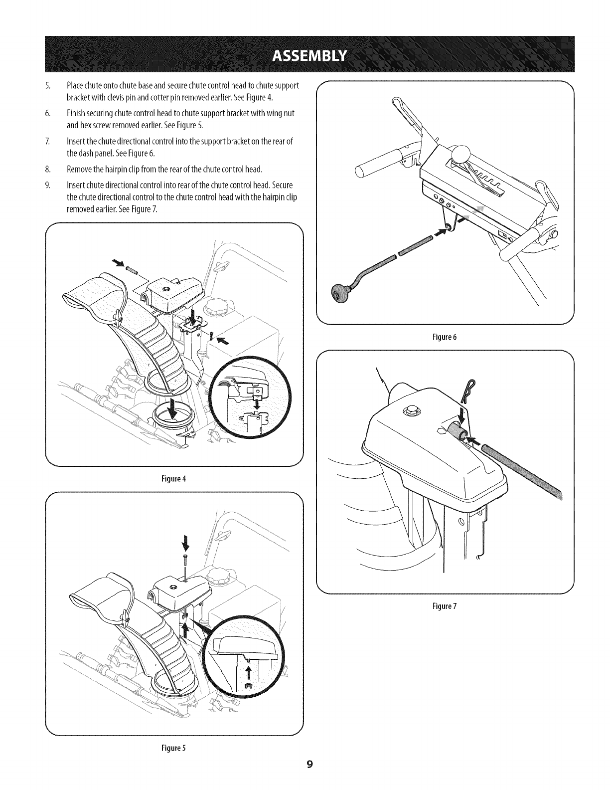
5. Placechuteontochutebaseandsecurechutecontrolheadto chutesupport
bracketwith clevispinandcotterpinremovedearlier.SeeFigure4.
6. Finishsecuringchutecontrolheadto chutesupportbracketwith wingnut
andhexscrewremovedearlier.SeeFigure5.
7. Insertthechutedirectionalcontrolintothesupportbracketontherearof
thedashpanel.SeeFigure6.
8. Removethehairpinclipfromtherearofthechutecontrolhead.
9. Insertchutedirectionalcontrolinto rearofthechutecontrolhead.Secure
thechutedirectionalcontrolto thechutecontrolheadwith thehairpinclip
removedearlier.SeeFigure7.
f
Figure4
f
Figure 6
f\
Figure7
Figure5
9
Set-Up f
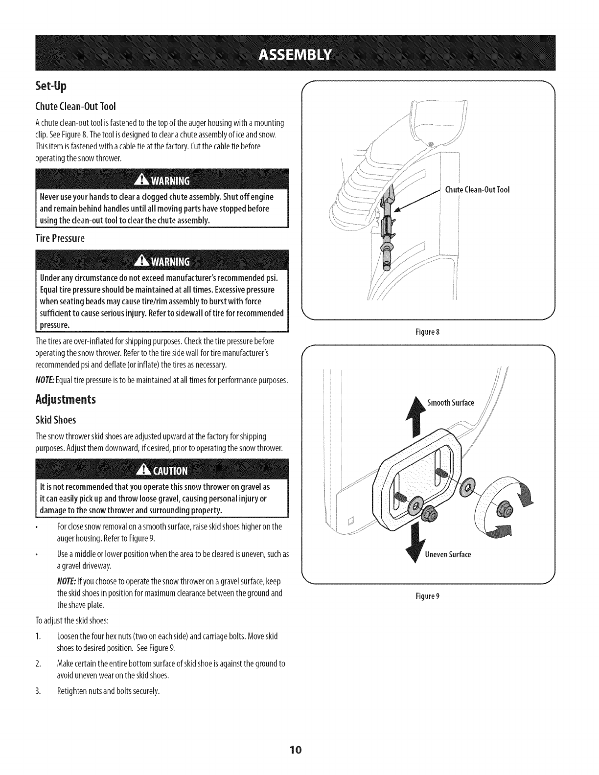
ChuteClean-OutTool
Achuteclean-outtool isfastenedto thetopoftheaugerhousingwith amounting
clip.SeeFigure8.Thetool isdesignedto cleara chuteassemblyof iceandsnow.
Thisitemisfastenedwitha cabletieat thefactory.Cutthecabletie before
operatingthesnowthrower.
Neveruseyour handsto clearacloggedchuteassembly,Shutoff engine
and remainbehindhandlesuntil all movingpartshavestoppedbefore
usingthe clean-outtool to clearthe chuteassembly.
TirePressure
Underany circumstancedo notexceedmanufacturer'srecommendedpsi.
Equaltire pressureshouldbemaintainedat alltimes. Excessivepressure
when seatingbeadsmaycausetirelrim assemblyto burstwith force
sufficient to causeseriousinjury. Referto sidewall of tire for recommended
pressure.
Thetiresareover-inflatedforshippingpurposes.Checkthetire pressurebefore
operatingthesnowthrower.Refertothetiresidewall for tiremanufacturer's
recommendedpsianddeflate(orinflate)thetiresasnecessary.
NOTE:Equaltire pressureisto bemaintainedat alltimesforperformancepurposes.
Adjustments
Skid Shoes
Thesnowthrowerskidshoesareadjustedupwardatthefactoryforshipping
purposes.Adjustthemdownward,if desired,priortooperatingthesnowthrower.
It isnotrecommendedthat you operatethis snowthrower on gravelas
itcaneasilypickupandthrow loosegravel,causingpersonalinjuryor
damageto thesnowthrower andsurroundingproperty.
Forclosesnowremovalon asmoothsurface,raiseskidshoeshigheronthe
augerhousing.Referto Figure9.
Useamiddleorlowerpositionwhentheareato beclearedisuneven,suchas
agraveldriveway.
NOTE:Ifyouchooseto operatethesnowthroweronagravelsurface,keep
theskidshoesinpositionformaximumclearancebetweenthegroundand
theshaveplate.
Toadjusttheskidshoes:
1. Loosenthefour hexnuts(twooneachside)andcarriagebolts.Moveskid
shoesto desiredposition.SeeFigure9.
2. Makecertainthe entirebottomsurfaceof skidshoeisagainstthegroundto
avoidunevenwearontheskidshoes.
ChuteClean-OutTool
/
/ii
Figure8
f
SmoothSurface
UnevenSurface
Figure9
3. Retightennutsandboltssecurely.
10
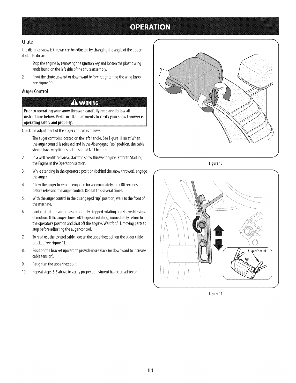
Thedistancesnowisthrowncanbeadjustedbychangingtheangleoftheupper
chute.Todoso:
2.
Stoptheenginebyremovingtheignitionkeyandloosentheplasticwing
knobfoundonthe left sideofthechuteassembly.
Pivotthechuteupwardordownwardbeforeretighteningthewingknob.
SeeFigure10.
AugerControl
Priorto operatingyoursnowthrower,carefully readand follow all
instructionsbelow.Performall adjustmentsto verifyyoursnowthrower is
operating safelyand properly.
Checktheadjustmentoftheaugercontrolasfollows:
1. Theaugercontrolislocatedon theleft handle.SeeFigure11inset.When
theaugercontrolisreleasedandinthedisengaged"up"position,thecable
shouldhaveverylittle slack.ItshouldNOTbetight.
2. Ina well-ventilatedarea,start thesnowthrowerengine.Referto Starting
theEngineintheOperationsection.
3. Whilestandingintheoperator'sposition(behindthesnowthrower),engage
theauger.
4. Allowtheaugerto remainengagedfor approximatelyten(10)seconds
beforereleasingtheaugercontrol.Repeatthisseveraltimes.
5. Withtheaugercontrolin thedisengaged"up" position,walkto thefrontof
themachine.
6. Confirmthat theaugerhascompletelystoppedrotatingandshowsNOsigns
of motion.IftheaugershowsANYsignsof rotating,immediatelyreturnto
theoperator'spositionandshutoff theengine.WaitforALLmovingpartsto
stopbeforeadjustingtheaugercontrol.
7. Toreadjustthecontrolcable,loosenthe upperhexboltontheaugercable
bracket.SeeFigure11.
8. Positionthebracketupwardto providemoreslack(ordownwardto increase
cabletension).
9. Retightentheupperhexbolt.
10. Repeatsteps2-6aboveto verifyproperadjustmenthasbeenachieved.
f
Figure10
\\
..........
.J
J
Figure11
11
Chute Assembly
\\\
cI
_ugerHousing_\\_, ,L!,
Augers
Drive Control
Gas Cap
\
Shift Lever
J
Auger Control
Chute Directional Control
Recoil Starter
Handle
Throttle
Control
Choke
Control
"Skid Shoe
:lectric Start
Button
Oil Drain Electric Starter Outlet
J
Figure12
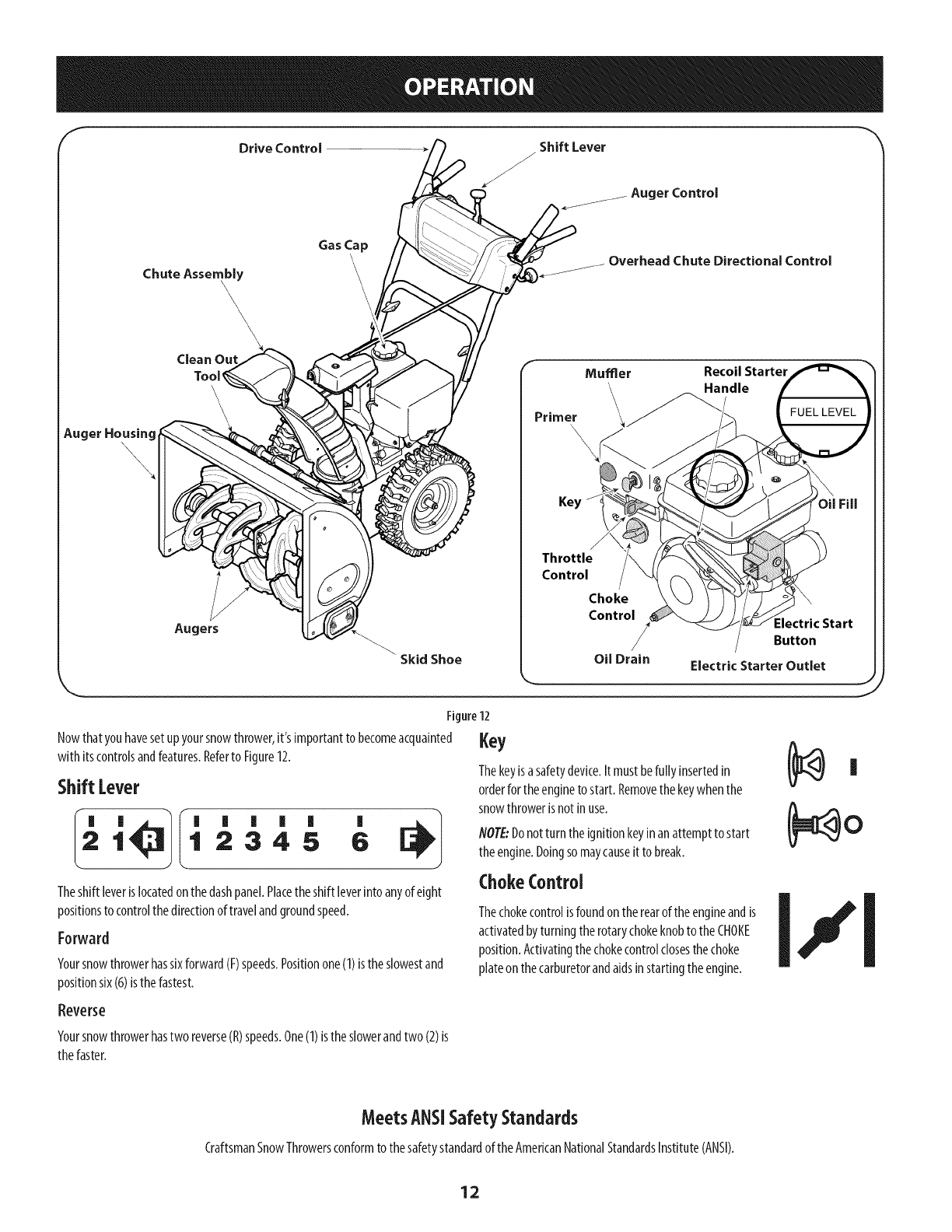
Nowthatyouhavesetupyoursnowthrower,it'simportantto becomeacquainted
with itscontrolsandfeatures.Referto Figure12.
ShiftLever
I_ '_1 ' ' ' ' ' '
12345 6
Theshift leveris locatedonthedashpanel.Placetheshiftleverintoanyofeight
positionsto controlthedirectionof travelandgroundspeed.
Forward
Yoursnowthrowerhassixforward(F)speeds.Positionone(1)isthe slowestand
positionsix(6)isthe fastest.
Key
Thekeyisasafetydevice.It mustbefully insertedin
orderfor theenginetostart. Removethekeywhenthe
snowthrowerisnotin use.
NOTE:Donot turntheignitionkeyinan attemptto start
theengine.Doingsomaycauseitto break.
ChokeControl
Thechokecontrolisfoundontherearoftheengineandis
activatedbyturningtherotarychokeknobto theCHOKE
position.Activatingthechokecontrolclosesthechoke
plateon thecarburetorandaidsinstartingtheengine.
|
Reverse
Yoursnowthrowerhastworeverse(R)speeds.One(1)lstheslowerandtwo(2)ls
thefaster.
MeetsANSiSafetySta.dards
CraftsmanSnowThrowersconformto thesafetystandardof the AmericanNationalStandardsInstitute(ANSI).
12
Throttlecontrol
Thethrottlecontrolislocatedontherearoftheengine.It regulatesthespeedofthe
engineandwill shutoffthe enginewhenmovedinto theSTOPposition.
Depressingtheprimerforcesfueldirectlyintothe _e 444
engine'scarburetorto aid incold-weatherstarting. 3X
RecoilStarter Handle
Thishandleisusedto manuallystarttheengine.
Electric Starter Button
Pressingtheelectricstarterbuttonengagestheengine'selectricstarterwhen
pluggedinto a 120Vpowersource.
Electric Starter Outlet
Requirestheuseof athree-prongoutdoorextensioncordanda 120Vpowersource/
walloutlet.
OUFill
Engineoillevelcanbecheckedandoiladdedthroughtheoil fill.
GasCap
Unthreadthegascapto addgasolinetothefueltank.
Auger
Whenengaged,theaugerbladesrotateanddrawsnowintotheaugerhousing.
ChuteAssembly
Snowdrawninto theaugerhousingisdischargedoutthechuteassembly.
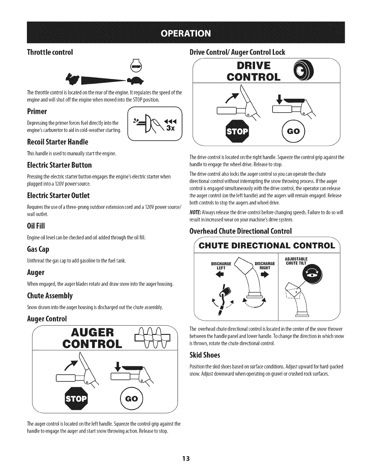
AugerControl
fAUGER
CONTROL
DriveControl/Auger Control Lock
f DRIVE
CONTROL
Thedrivecontrolislocatedontheright handle.Squeezethecontrolgripagainstthe
handleto engagethewheeldrive.Releaseto stop.
Thedrivecontrolalsolockstheaugercontrolsoyoucanoperatethechute
directionalcontrolwithoutinterruptingthesnowthrowingprocess.Iftheauger
controlisengagedsimultaneouslywiththedrivecontrol,theoperatorcanrelease
theaugercontrol(ontheleft handle)andtheaugerswill remainengaged.Release
bothcontrolsto stoptheaugersandwheeldrive.
NOTE:Alwaysreleasethedrivecontrolbeforechangingspeeds.Failureto dosowill
resultinincreasedwearon yourmachine'sdrivesystem.
OverheadChute Directional Control
/CHUTE DIRECTIONAL CONTROL
DISCHARGE
LEFT
ADJUSTABLE
CHUTETILT
J
Theoverheadchutedirectionalcontrolislocatedin thecenterofthesnowthrower
betweenthe handlepanelandlowerhandle.Tochangethedirectioninwhichsnow
isthrown,rotatethechutedirectionalcontrol.
SkidShoes
Positiontheskidshoesbasedonsurfaceconditions.Adjustupwardforhard-packed
snow.Adjustdownwardwhenoperatingongravelorcrushedrocksurfaces.
Theaugercontrolislocatedon theleft handle.Squeezethecontrolgripagainstthe
handleto engagetheaugerandstartsnowthrowingaction.Releaseto stop.
13
Clean-OutTool
Neveruseyour handsto clearacloggedchuteassembly.Shutoff engine
and remainbehindhandlesuntil all movingparts havestoppedbefore
usingthe clean-outtool to clearthe chuteassembly.
Thechutedean-outtool isconvenientlyfastenedto therearoftheaugerhousing
with amountingclip.Shouldsnowandicebecomelodgedin thechuteassembly
duringoperation,proceedasfollowsto safelycleanthechuteassemblyandchute
opening:
1. ReleaseboththeAugerControlandthe DriveControl.
2. Stoptheenginebyremovingthe ignitionkey.
3. Removetheclean-outtool fromtheclipwhichsecuresit to the rearof the
augerhousing.
4. Usetheshovel-shapedendof theclean-outtool to dislodgeandscoopany
snowandicewhichhasformedinandnearthechuteassembly.
5. Refastentheclean-outtool to themountingdip on therearof theauger
housing,reinserttheignitionkeyandstartthesnowthrower'sengine.
6. Whilestandingintheoperator'sposition(behindthesnowthrower),engage
theaugercontrolforafewsecondstoclearanyremainingsnowandicefrom
thechuteassembly.
BeforeStartingEngine
Read,understand,andfollow all instructionsandwarningsonthe
machineandinthis manualbeforeoperating.
Oil
Theunit wasshippedwith oilintheengine.Checkoillevelbeforeeachoperationto
ensureadequateoilin theengine.
flO?E:Besureto checktheengineonalevelsurfacewith theenginestopped.
1. Removetheoilfiller cap/dipstickandwipethedipstickclean.
2. Insertthecap/dipstickinto theoil filler neck,butdo NOTscrewit in.
3. Removetheoilfiller cap/dipstick.Ifthe levelislow,slowlyaddoil(5W-30,
with aminimumclassificationof SF/SG)until oil levelregistersbetweenhigh
(H)andlow(L).
4.
flOTE:Donotoverfill.Overfillingwith oilmayresultin enginesmoking,hard
startingorsparkplugfouling.
Replaceandtightencap/dipstickfirmlybeforestartingengine.
Gasoline
Useautomotivegasoline(unleadedorlowleadedto minimizecombustionchamber
deposits)witha minimumof87 octane.Gasolinewith up to 10%ethanolor15%
MTBE(MethylTertiaryButylEther)canbeused.Neveruseanoil/gasolinemixture
ordirtygasoline.Avoidgettingdirt, dust,orwaterinthefueltank.DONOTuseE85
gasoline.
Refuelin awell-ventilatedareawith theenginestopped.Donotsmokeor
allowflamesorsparksin theareawheretheengineisrefueledorwhere
gasolineisstored.
Donotoverfillthefueltank.Afterrefueling,makesurethetankcapisclosed
properlyandsecurely.
Becarefulnot to spillfuelwhenrefueling.Spilledfuel orfuelvapormay
ignite.If anyfuelisspilled,makesuretheareaisdry beforestartingthe
engine.
Avoidrepeatedorprolongedcontactwith skinorbreathingofvapor.
Useextremecarewhenhandling gasoline.Gasolineis extremely
flammableandthe vaporsareexplosive.Neverfuel the machineindoorsor
while the engineishotor running. Extinguishcigarettes,cigars,pipesand
othersourcesof ignition.
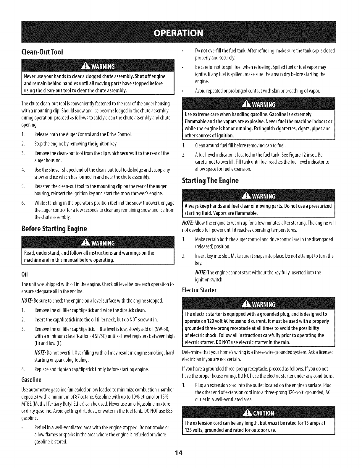
1.
2.
Cleanaroundfuelfill beforeremovingcapto fuel.
Afuel levelindicatorislocatedinthefueltank.SeeFigure12inset.Be
carefulnotto overfill.Filltankuntil fuel reachesthe fuellevelindicatorto
allowspacefor fuelexpansion.
Starting TheEngine
Alwayskeephandsandfeet clearof movingparts.Donot usea pressurized
starting fluid. Vaporsareflammable.
flOTE:Allowtheengineto warmupfor afewminutesafter starting.Theenginewill
notdevelopfull poweruntil it reachesoperatingtemperatures.
1. Makecertainboththeaugercontrolanddrivecontrolarein thedisengaged
(released)position.
2. Insertkeyinto slot.Makesureit snapsinto place.Donotattemptto turnthe
key.
NOTE:Theenginecannotstartwithoutthekeyfully insertedinto the
ignitionswitch.
ElectricStarter
Theelectric starter isequippedwith a groundedplug, andis designedto
operateon 120volt AChouseholdcurrent. It must beusedwith a properly
groundedthree-prong receptacleat all timesto avoidthe possibility
of electricshock.Followall instructionscarefully prior to operating the
electricstarter. DONOTuseelectricstarter in the rain.
Determinethatyourhome'swring isathree-wiregroundedsystem.Aska licensed
electricianif youarenotcertain.
Ifyouhavea groundedthree-prongreceptacle,proceedasfollows.If youdonot
havetheproperhousewiring,DONOTusetheelectricstarterunderanyconditions.
1. Pluganextensioncordinto theoutletlocatedontheengine'ssurface.Plug
theotherendofextensioncordintoathree-prong120-volt,grounded,AC
outlet inawell-ventilatedarea.
Theextensioncordcanbeanylength, but must be ratedfor 15ampsat
125volts,groundedand ratedfor outdoor use.
14
2. Movethrottle controlto FAST(rabbit)_Jl__ position.
3 MovechoketotheCHOKEI,'I pos t on co,deng nestart),fengine s
warm,placechokein RUNposition.
4. Pushprimerthree(3)times,makingsureto covervent holeinprimerbulb
whenpushing.Ifengineiswarm,pushprimeronlyonce.Alwayscovervent
holewhenpushing.Coolweathermayrequireprimingto berepeated.
5. Pushstarterbuttonto startengine.Oncetheenginestarts,immediately
releasestarterbutton.Electricstarterisequippedwith thermaloverload
protection;systemwill temporarilyshut-downto allowstarterto coolif
electricstarterbecomesoverloaded.
6. Asthe enginewarms,slowlyrotatethechokecontrolto RUNposition.Ifthe
enginefalters,restartengineandrunwith chokeat half-chokepositionfor a
shortperiodof time,andthenslowlyrotatethechokeinto RUNposition.
Afterengineisrunning,disconnectpowercordfromelectricstarter.When
disconnecting,alwaysunplugtheendat thewall outletbeforeunplugging
theoppositeendfromtheengine.
RecoilStarter
Donot pull the starter handlewhilethe enginerunning.
1. Movethrottle controlto FAST(rabbit)_ _j position.
2. Movechoketo the CHOKEI,.1position(coldenginestart).If engineis
warm,placechokein RUNposition.
3. Pushprimerthree(3)times,makingsureto covervent holewhenpushing.
If engineiswarm,pushprimeronlyonce.Alwayscoverventholewhen
pushing.Coolweathermayrequireprimingto berepeated.
4. Pullgentlyonthestarterhandleuntil it beginsto resist,then pullquickly
andforcefullyto overcomethecompression.Donotreleasethe handleand
allowit to snapback.ReturnropeSLOWLYto originalposition.If required,
repeatthisstep.
5. Asthe enginewarms,slowlyrotatethechokecontrolto RUNposition.Ifthe
enginefalters,restartengineandrunwith chokeat half-chokepositionfor a
shortperiodof time,andthenslowlyrotatethechokeinto RUNposition.
Toavoidunsupervisedengineoperation, neverleavethe machine
unattendedwith theenginerunning. Turnthe engineoff after useand
removekey.
Stopping TheEngine
Afteryouhavefinishedsnow-throwing,runenginefor afewminutesbefore
stoppingto helpdryoffany moistureon theengine.
1. Movethrottle controlto OFFposition.
2. Removethekey.Removingthe keywill reducethepossibilityof
unauthorizedstartingof theenginewhileequipmentisnotinuse.Keepthe
keyina safeplace.Theenginecannotstartwithout thekey.
3. Wipeanymoistureawayfromthecontrolsontheengine.
ToEngageDrive
1. Withthethrottlecontrolinthe Fast(rabbit)_ _1 position,moveshift lever
into oneof thesixforward(F)positionsortwo reverse(R)positions.Selecta
speedappropriatefor thesnowconditionsanda paceyou'recomfortable
with.
flOTE:Whenselectinga DriveSpeed,usetheslowerspeedsuntilyouare
comfortableandfamiliarwith theoperationof thesnowthrower.
2. Squeezethedrivecontrolagainstthehandleandthesnowthrowerwill
move.Releaseit anddrivemotionwill stop.
NOTE:NEVERrepositiontheshift lever(changespeedsordirectionof travel)
without first releasingthedrivecontrolandbringingthesnowthrowerto a
completestop.Doingsowill resultin prematurewearto thesnowthrower'sdrive
system.
ToEngageAuger
Toengagetheaugerandstartthrowingsnow,squeezetheaugercontrol
againstthe left handle.Releaseto stoptheauger.
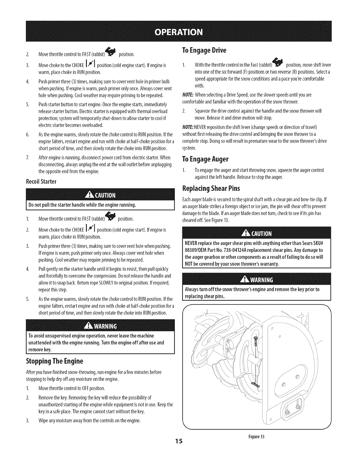
ReplacingShearPins
Eachaugerbladeissecuredto the spiralshaftwith ashearpinandbow-tieclip.If
anaugerbladestrikesa foreignobjectoricejam,thepinwill shearoff to prevent
damageto theblade.Ifan augerbladedoesnotturn,checkto seeif itspinhas
shearedoff. SeeFigure13.
NEVERreplacethe augershearpinswith anything otherthan SearsSKU#
88389/0EMPart No.738-04124Areplacementshearpins.Any damageto
the augergearboxorother componentsasa result of failing to do sowill
NOTbe coveredbyyour snowthrower'swarranty.
Alwaysturn off the snowthrower'sengineand removethe keypriorto
replacingshearpins.
E
J
Figure13
15
MAINTENANCESCHEDULE
Beforeperforminganytypeof maintenance/service,disengageall controls
andstopthe engine.Wait until allmoving partshavecometo a complete
stop. Disconnectsparkplug wire and grounditagainstthe engineto
preventunintendedstarting.
EachUseand every 5hours
Ist 5hours
Annuallyor25hours
Annuallyor50hours
Annuallyor100hours
BeforeStorage
Followthemaintenanceschedulegivenbelow.Thischartdescribesservice
guidelinesonly.Usethe ServiceLogcolumnto keeptrackofcompleted
maintenancetasks.TolocatethenearestSearsServiceCenterorto scheduleservice,
simplycontactSearsat 1-800-4-MY-HOME®.
1. Engineoil level
2. Looseormissinghardware
3. Unitandengine.
1. Englneoil
1. Sparkplug
2. Controllinkagesandpivots
3. Wheels
4. GearshaftandAugershaft
1. Englneoil
1. Sparkplug
1. Fuelsystem
GENERALRECOMMENDATIONS
CheckingEngineOil
Beforelubricating, repairing,or inspecting,disengageall controlsandstop
engine.Waituntil all movingparts havecometo acompletestop.
NOTE:Checkthe oillevelbeforeeachuseto besurecorrectoillevelismaintained.
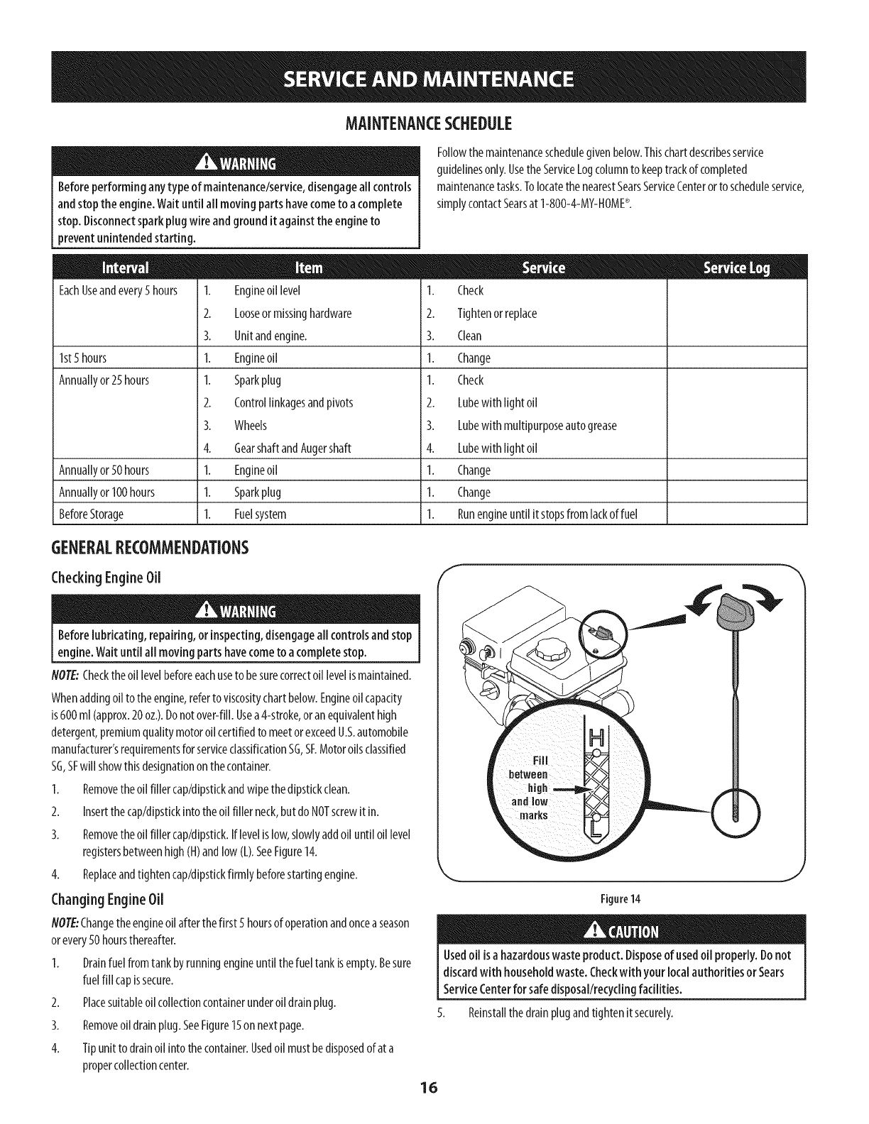
Whenaddingoil to theengine,referto viscositychartbelow.Engineoilcapacity
is600ml(approx.20oz.).Donotover-fill.Usea4-stroke,oranequivalenthigh
detergent,premiumqualitymotoroilcertifiedto meetorexceedU.S.automobile
manufacturer'srequirementsforserviceclassificationSG,SF.Motoroilsclassified
SG,SFwill showthisdesignationonthecontainer.
1. Removetheoilfiller cap/dipstkkandwipethedipstickclean.
2. Insertthecap/dipstickintotheoil filler neck,butdo NOTscrewitin.
3. Removetheoilfiller cap/dipstick.Iflevelislow,slowlyaddoiluntil oil level
registersbetweenhigh(H)andlow(L).SeeFigure14.
4. Replaceandtightencap/dipstickfirmlybeforestartingengine.
Changing EngineOil
NO/E:Changetheengineoilafterthefirst 5 hoursof operationandoncea season
orevery50 hoursthereafter.
1. Drainfuel fromtankbyrunningengineuntil thefueltank isempty.Besure
fuelfill capissecure.
2. Placesuitableoilcollectioncontainerunderoil drainplug.
3. Removeoildrainplug.SeeFigure15on nextpage.
4. Tipunit to drainoil intothecontainer.Usedoil mustbedisposedofat a
propercollectioncenter.
1. Check
2. Tightenorreplace
3. Clean
1. Change
1. Check
2. Lubewith light oil
3. Lubewith multipurposeautogrease
4. Lubewith light oil
1. Change
1. Change
1. Runengineuntil itstopsfromlackoffuel
Figure14
16
Usedoil isa hazardouswaste product.Disposeof usedoil properly.Donot
discardwith householdwaste.Checkwithyour localauthorities or Sears
ServiceCenterfor safedisposal/recyclingfacilities.
Reinstallthedrainplugandtightenitsecurely.
J
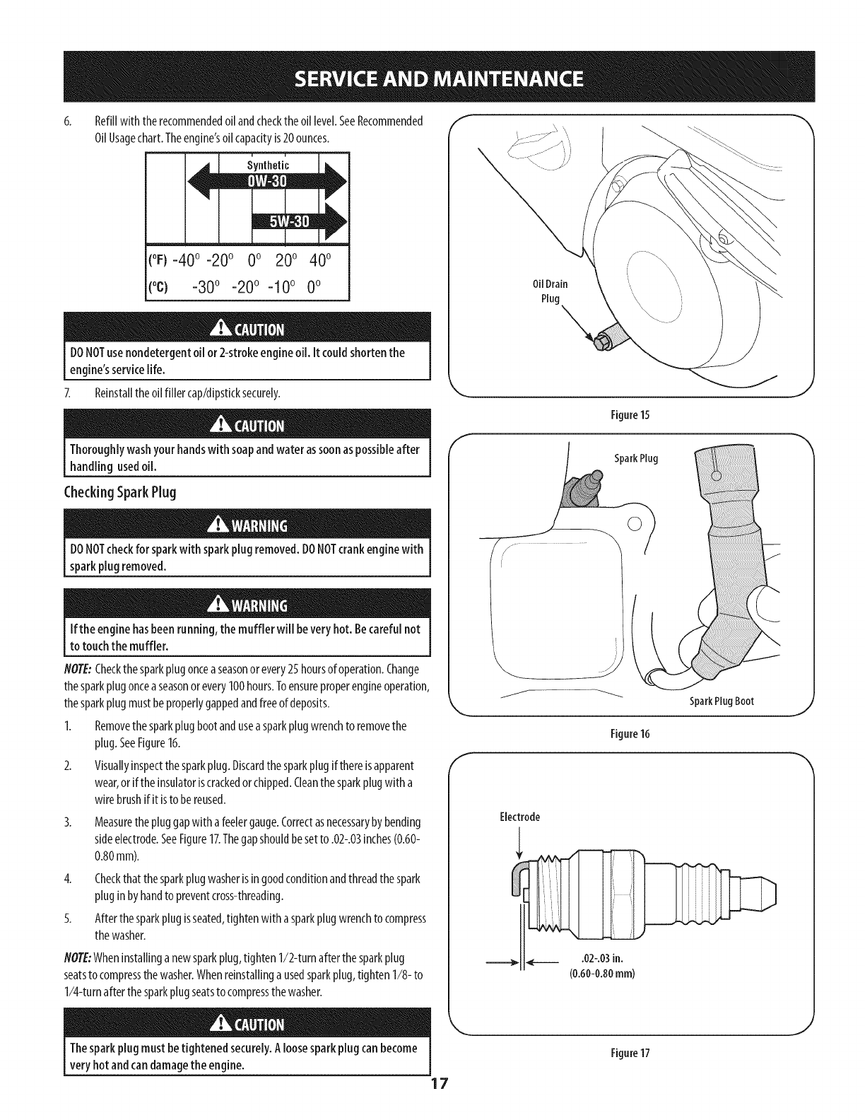
Refillwith therecommendedoilandchecktheoil level.SeeRecommended
OilUsagechart.Theengine'soilcapacityis20ounces.
(%-40 °-20 o 0o 20o 40o
(oc) -30° -20° -10 ° 0°
DONOTuse nondetergentoil or 2-strokeengineoil. it couldshorten the
engine'sservicelife.
7. Reinstalltheoil filler cap/dipsticksecurely.
Thoroughlywashyour handswith soapandwater assoonaspossibleafter
handlingusedoil.
CheckingSparkPlug
DONOTcheckfor sparkwith sparkplug removed.DONOTcrankenginewith
sparkplug removed.
Ifthe enginehasbeenrunning,the muffler will beveryhot. Becarefulnot
to touchthe muffler.
NOTE:Checkthe sparkplugonceaseasonor every25 hoursof operation.Change
thesparkplugonceaseasonorevery100hours.Toensureproperengineoperation,
thesparkplugmustbeproperlygappedandfreeof deposits.
1. Removethesparkplugbootandusea sparkplugwrenchto removethe
plug.SeeFigure16.
2. Visuallyinspectthesparkplug.Discardthesparkplugifthereisapparent
wear,orif theinsulatoriscrackedorchipped.Cleanthesparkplugwith a
wirebrushifit isto bereused.
3. Measurethepluggapwith afeelergauge.Correctasnecessarybybending
sideelectrode.SeeFigure17.Thegapshouldbesetto .02-.03inches(0.60-
0.80mm).
4. Checkthatthesparkplugwasherisin goodconditionandthreadthespark
pluginbyhandto preventcross-threading.
5. Afterthe sparkplug isseated,tightenwith asparkplugwrenchto compress
thewasher.
NOTE:Wheninstallinganewsparkplug,tighten1/2-turnafterthesparkplug
seatsto compressthe washer.Whenreinstallinga usedsparkplug,tighten 1/8-to
1/4-turnafterthesparkplugseatsto compressthewasher.
Oil Drain
Plug \
Figure15
E
SparkPlug
SparkPlugBoot
Figure16
Electrode
Thesparkplug mustbetightened securely.Aloosesparkplugcan become
very hotandcan damagethe engine.
17
Figure17
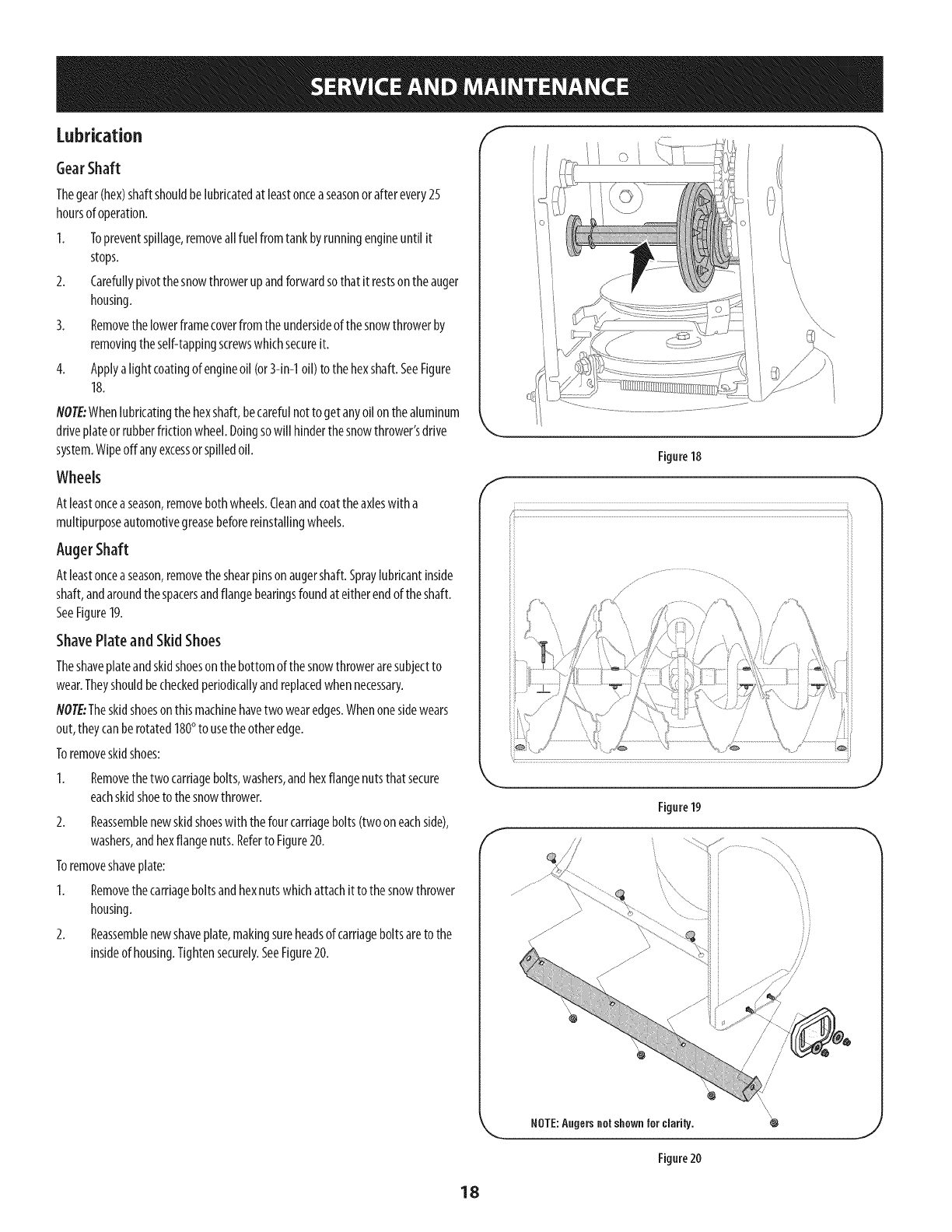
Lubrication "I
GearShaft
Thegear(hex)shaftshouldbelubricatedat leastonceaseasonorafter every25
hoursof operation.
I. Topreventspillage,removeall fuelfromtankbyrunningengineuntil it
stops.
2. Carefullypivotthesnowthrowerupandforwardsothat it restsontheauger
housing.
3. Removethelowerframecoverfrom theundersideof thesnowthrowerby
removingtheself-tappingscrewswhichsecureit.
4. Applya lightcoatingof engineoil(or3-in-1oil) to thehexshaft.SeeFigure
18.
NOTE:Whenlubricatingthe hexshaft,becarefulnotto getanyoilonthealuminum
driveplateorrubberfrictionwheel.Doingsowill hinderthesnowthrower'sdrive
system.Wipeoffanyexcessorspilledoil.
Wheels
Atleastonceaseason,removebothwheels.Cleanandcoattheaxleswitha
multipurposeautomotivegreasebeforereinstallingwheels.
AugerShaft
Atleastonceaseason,removetheshearpinsonaugershaft.Spraylubricantinside
shaft,andaroundthespacersandflangebearingsfoundat eitherendof theshaft.
SeeFigure19.
ShavePlate and Skid Shoes
Theshaveplateandskidshoeson thebottomofthesnowthroweraresubjectto
wear.Theyshouldbecheckedperiodkallyandreplacedwhennecessary.
flOT£:Theskidshoeson thismachinehavetwo wearedges.Whenonesidewears
out,theycanberotated180°to usethe otheredge.
Toremoveskidshoes:
Removethetwocarriagebolts,washers,andhexflangenutsthatsecure
eachskidshoetothesnowthrower.
2. Reassemblenewskidshoeswith thefourcarriagebolts(twoon eachside),
washers,andhexflangenuts.Referto Figure20.
Toremoveshaveplate:
1. Removethecarriageboltsandhexnutswhichattachitto thesnowthrower
housing.
2. Reassemblenewshaveplate,makingsureheadsof carriageboltsareto the
insideof housing.Tightensecurely.SeeFigure20.
f
Figure18
J
f_S /
f
Figure19
NOTE:Angers not shown for clarity. 4_
Figure20
18
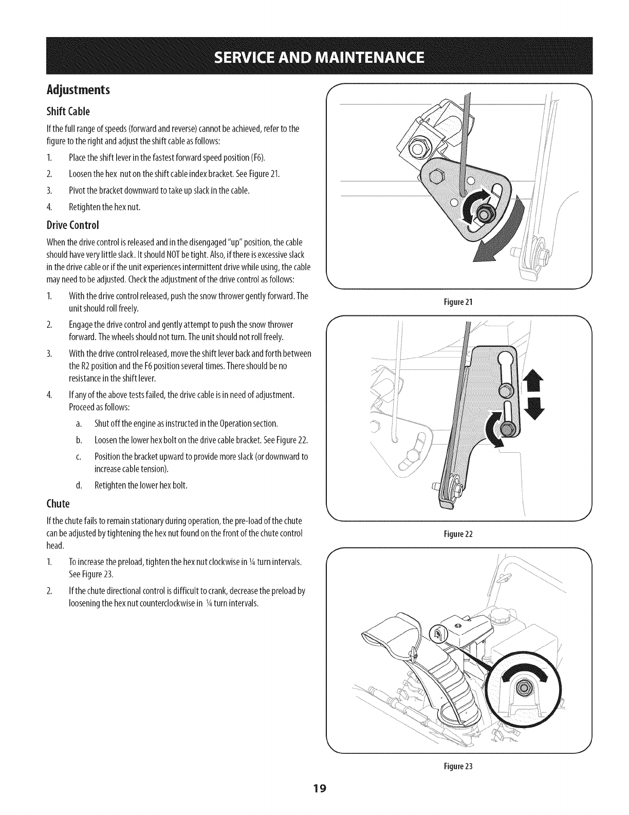
Adjustments f
Shift Cable
I,
2.
3.
4.
Drive
If the full rangeof speeds(forwardandreverse)cannotbeachieved,referto the
figureto theright andadjusttheshift cableasfollows:
Placetheshift leverinthefastestforwardspeedposition(F6).
Loosenthehex nutontheshift cableindexbracket.SeeFigure21.
Pivotthebracketdownwardtotakeupslackinthecable.
Retightenthehexnut.
Control
Whenthedrivecontrolis releasedandinthedisengaged"up" position,thecable
shouldhaveverylittle slack.ItshouldNOTbetight. Also,ifthereisexcessiveslack
inthedrivecableor iftheunit experiencesintermittentdrivewhileusing,thecable
mayneedto beadjusted.Checktheadjustmentof thedrivecontrolasfollows:
1. Withthedrivecontrolreleased,pushthesnowthrowergentlyforward.The
unit shouldroll freely.
2. Engagethedrivecontrolandgentlyattemptto pushthesnowthrower
forward.Thewheelsshouldnotturn. Theunit shouldnot roll freely.
3. With thedrivecontrolreleased,movetheshift leverbackandforth between
theR2positionandthe F6positionseveraltimes.Thereshouldbeno
resistanceintheshift lever.
4, If anyof theabovetestsfailed,thedrivecableisinneedof adjustment.
Proceedasfollows:
a. Shutoff theengineasinstructedinthe Operationsection.
b. Loosenthelowerhexboltonthedrivecablebracket.SeeFigure22.
c. Positionthebracketupwardto providemoreslack(ordownwardto
increasecabletension).
d. RetJghtenthelowerhexbolt.
Chute
If the chutefallsto remainstationaryduringoperation,the pre-loadof thechute
canbeadjustedbytighteningthehexnutfoundonthefront ofthechutecontrol
head.
2.
Toincreasethepreload,tightenthehexnutclockwisein lg turnintervals.
SeeFigure23.
If thechutedirectionalcontrolisdifficult to crank,decreasethepreloadby
looseningthehexnutcounterclockwisein lg turnintervals.
/
E
Figure21
Figure22
//
J
Figure23
19
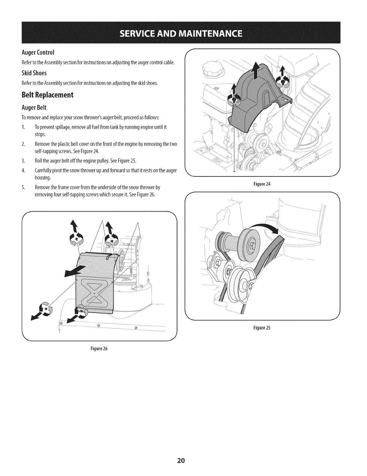
AugerControl
Referto theAssemblysectionforinstructionson adjustingtheaugercontrolcable.
Skid Shoes
Referto theAssemblysectionforinstructionson adjustingtheskidshoes.
8eR Replacement
Auger Belt
Toremoveandreplaceyoursnowthrower'saugerbelt,proceedasfollows:
I. Topreventspillage,removeall fuelfromtankbyrunningengineuntil it
stops.
2. Removetheplasticbeltcoveronthefrontof theenginebyremovingthetwo
self-tappingscrews.SeeFigure24.
3. Rolltheaugerbeltoffthe enginepulley.SeeFigure25.
4. Carefullypivotthesnowthrowerupandforwardsothat it restsontheauger
housing.
5. Removetheframecoverfromtheundersideof thesnowthrowerby
removingfourself-tappingscrewswhichsecureit. SeeFigure26.
f
Figure24
J
Figure 25
,J
.J
Figure 26
2O
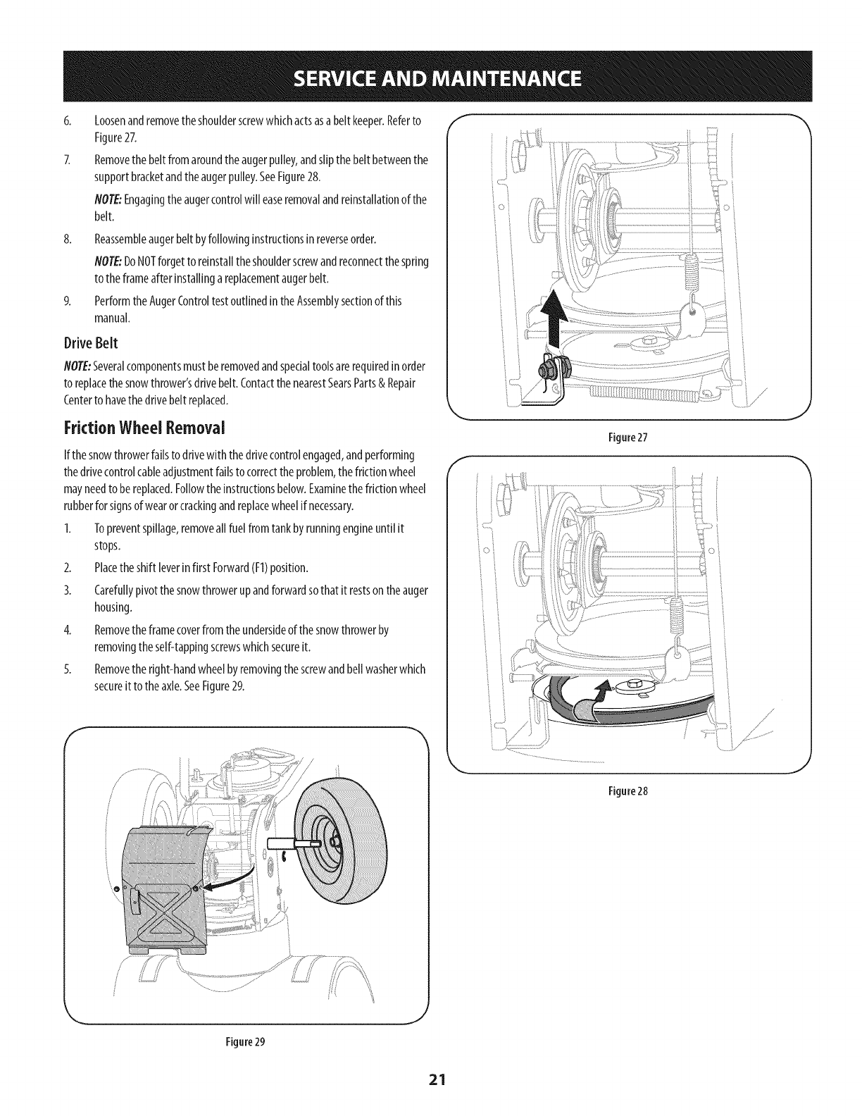
8.
Loosenandremovetheshoulderscrewwhichactsasabelt keeper.Referto
Figure27.
Removethebeltfromaroundtheaugerpulley,andslipthebelt betweenthe
supportbracketandtheaugerpulley.SeeFigure28.
NOTE:Engagingtheaugercontrolwill easeremovalandreinstallationof the
belt.
Reassembleaugerbeltbyfollowinginstructionsinreverseorder.
NOTE:DoNOTforgetto reinstalltheshoulderscrewandreconnectthespring
to theframeafterinstallingareplacementaugerbelt.
Performthe AugerControltestoutlinedintheAssemblysectionof this
manual.
Drive Belt
NOTE:Severalcomponentsmustberemovedandspecialtoolsarerequiredinorder
to replacethesnowthrower'sdrivebelt.ContactthenearestSearsParts& Repair
Centerto havethedrivebelt replaced.
FrictionWheelRemoval
If thesnowthrowerfailsto drivewith thedrivecontrolengaged,andperforming
thedrivecontrolcableadjustmentfailsto correcttheproblem,thefrictionwheel
mayneedto bereplaced.Followtheinstructionsbelow.Examinethefrictionwheel
rubberfor signsofwearorcrackingandreplacewheelifnecessary.
1. Topreventspillage,removeall fuelfromtankbyrunningengineuntil it
stops.
2. Placetheshift leverinfirst Forward(F1)position.
3. Carefullypivotthesnowthrowerupandforwardsothat itrestson theauger
housing.
4. Removetheframecoverfromtheundersideof thesnowthrowerby
removingtheself-tappingscrewswhichsecureit.
5. Removetheright-handwheelbyremovingthescrewandbellwasherwhich
secureitto theaxle.SeeFigure29.
F
Figure27
Figure28
J
Figure29
21
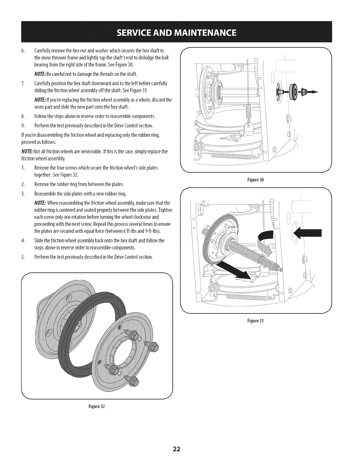
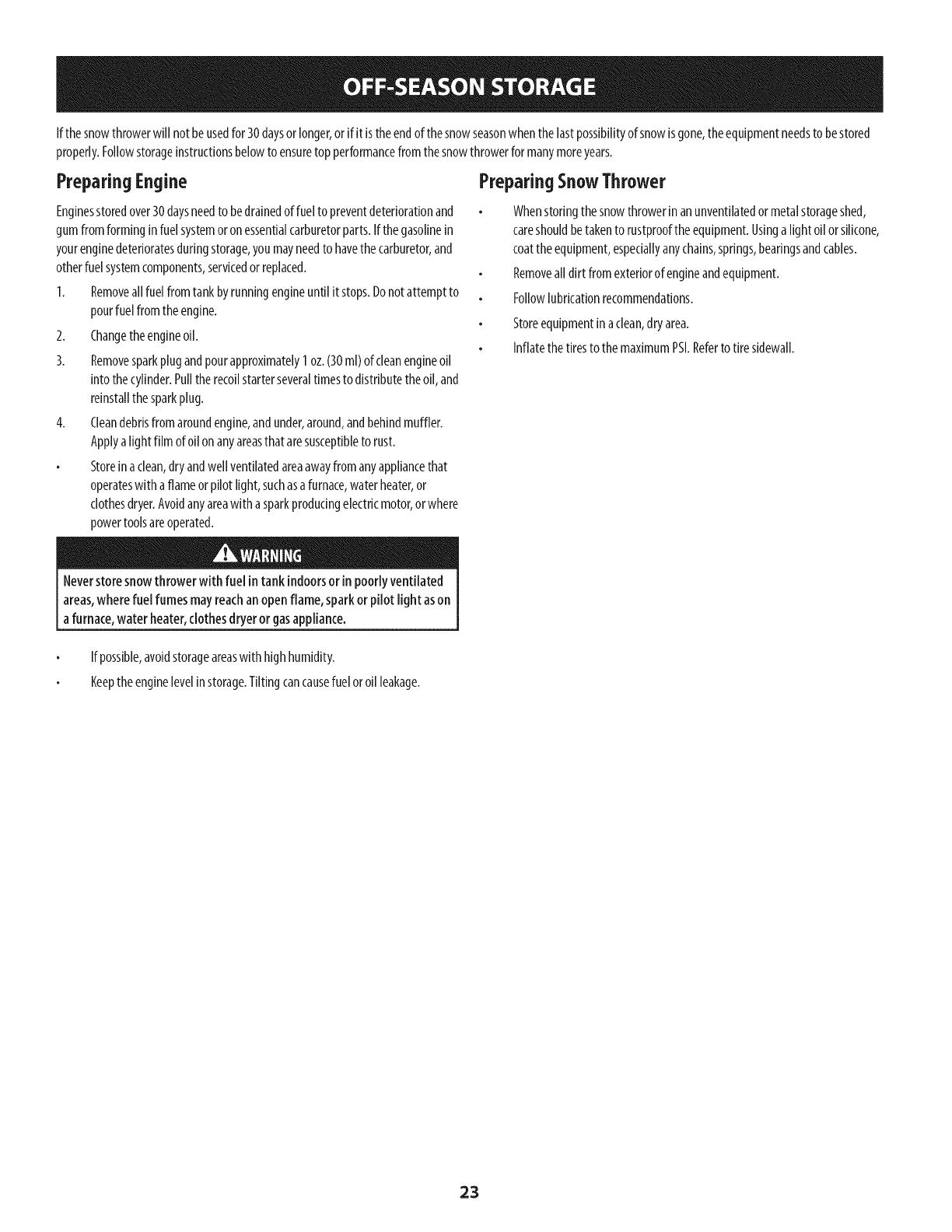
6. Carefullyremovethehexnutandwasherwhichsecuresthehexshaftto
thesnowthrowerframeandtightlytap theshaft'sendto dislodgetheban
bearingfromthe rightsideoftheframe.SeeFigure30.
NOTE:Becarefulnotto damagethethreadsonthe shaft.
7. Carefullypositionthe hexshaftdownwardandto the [eft beforecarefuNy
slidingthefrictionwheelassemblyoff theshaft.SeeFigure31.
NOTE:If you'rereplacingthefrictionwheelassemblyasawhole,discardthe
wornpartandslidethenewpartontothehexshall
8. FoNowthestepsaboveinreverseorderto reassemblecomponents.
9. PerformthetestpreviouslydescribedintheDriveControlsection.
Ifyou'redisassemblingthefrictionwheelandreplacingonlytherubberring,
proceedasfollows:
NOTE:Notallfrictionwheelsareserviceable.If thisisthecase,simplyreplacethe
frictionwheelassembly.
1. Removethefour screwswhichsecurethefrictionwheel'ssideplates
together.SeeFigure32.
2. Removetherubberringfrombetweentheplates.
3. Reassemblethesideplateswith anewrubberring.
NOTE:Whenreassemblingthefriction wheelassembly,makesurethat the
rubberringiscenteredandseatedpropertybetweenthesideplates.Tighten
eachscrewonlyonerotationbeforeturningthewheelclockwiseand
proceedingwith thenextscrew.Repeatthis processseveraltimesto ensure
theplatesaresecuredwith equalforce(between6ft-[bsand9ft-[bs).
4. SlidethefrictionwheelassemblybackontothehexshaftandfoNowthe
stepsaboveinreverseorderto reassemblecomponents.
5. PerformthetestpreviouslydescribedintheDriveControlsection.
f
f
Figure30
J
Figure31
J
Figure 32
,J
22
If the snowthrowerwill notbeusedfor 30daysorlonger,orif it is theendof thesnowseasonwhenthelastpossibilityof snowisgone,theequipmentneedsto bestored
properly.Followstorageinstructionsbelowto ensuretopperformancefromthesnowthrowerformanymoreyears.
PreparingEngine
Enginesstoredover30daysneedto bedrainedof fuel to preventdeteriorationand
gumfromforminginfuelsystemoronessentialcarburetorparts.If thegasolinein
yourenginedeterioratesduringstorage,youmayneedto havethecarburetor,and
otherfuelsystemcomponents,servicedorreplaced.
1. Removeallfuel fromtankbyrunningengineuntil it stops.Donotattemptto
pourfuelfromtheengine.
2. Changetheengineoil.
3. Removesparkplugandpourapproximately1oz.(30ml)ofcleanengineoil
into thecylinder.Pulltherecoilstarterseveraltimesto distributetheoil, and
reinstallthesparkplug.
4. Cleandebrisfromaroundengine,andunder,around,andbehindmuffler.
Applya lightfilm ofoil on anyareasthat aresusceptibleto rust.
Storeinaclean,dryandwellventilatedareaawayfromanyappliancethat
operateswith aflameorpilot light,suchasa furnace,waterheater,or
clothesdryer.Avoidanyareawitha sparkproducingelectricmotor,orwhere
powertoolsareoperated.
PreparingSnowThrower
Whenstoringthe snowthrowerin anunventilatedormetalstorageshed,
careshouldbetakento rustprooftheequipment.Usinga lightoil orsilicone,
coattheequipment,especiallyanychains,springs,bearingsandcables.
Removeall dirt fromexteriorof engineandequipment.
Followlubricationrecommendations.
Storeequipmentinaclean,dryarea.
Inflatethe tiresto the maximumPSI.Referto tire sidewall.
Neverstore snowthrower with fuel intank indoorsor in poorlyventilated
areas,wherefuelfumes mayreachanopenflame, sparkor pilotlight ason
a furnace,water heater,clothesdryeror gasappliance.
If possible,avoidstorageareaswith highhumidity.
Keeptheenginelevelinstorage.Tiltingcancausefueloroil leakage.
23
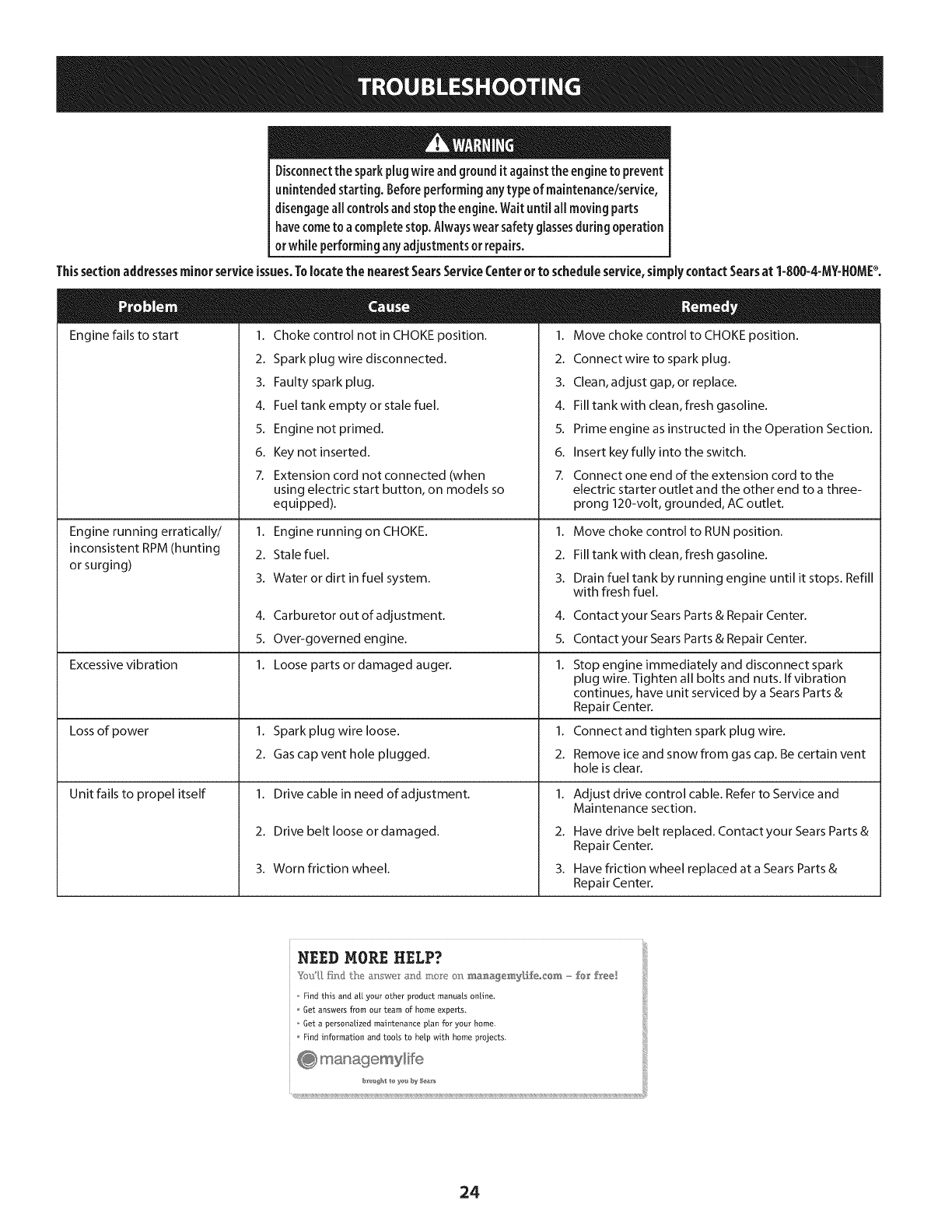
Disconnectthe sparkplug wireandgrounditagainstthe engineto prevent
unintendedstarting. Beforeperforminganytypeof maintenance/service,
disengageallcontrolsandstoptheengine.Waituntil aHmovingparts
havecometo a completestop.Alwayswear safetyglassesduringoperation
or while performingany adjustmentsor repairs.
Thissectionaddressesminorserviceissues.Tolocatethe nearestSearsServiceCenterorto scheduleservice,simplycontactSearsat 1-800-4-MY=HOMP.
Engine fails to start 1.
2.
3.
4.
5.
6.
7.
Choke control not in CHOKE position.
Spark plug wire disconnected.
Faulty spark plug.
Fuel tank empty or stale fuel.
Engine not primed.
Key not inserted.
Extension cord not connected (when
1. Move choke control to CHOKE position.
2. Connectwire to spark plug.
3. Clean, adjust gap, or replace.
4. Fill tank with clean, fresh gasoline.
5. Prime engine as instructed in the Operation Section.
6. Insert key fully into the switch.
7. Connect one end of the extension cord to the
Engine running erratically/
inconsistent RPM (hunting
or surging)
Excessive vibration
Lossof power
Unit fails to propel itself
using electric start button, on models so
equipped).
1. Engine running on CHOKE.
2. Stale fuel.
3. Water or dirt in fuel system.
4. Carburetor out of adjustment.
5. Over-governed engine.
1. Loose parts or damaged auger.
1. Spark plug wire loose.
2. Gas cap vent hole plugged.
1. Drive cable in need of adjustment.
2. Drive belt loose or damaged.
3. Worn friction wheel.
electric starter outlet and the other end to a three-
prong 120-volt, grounded, ACoutlet.
1. Move choke control to RUN position.
2. Fill tank with clean, fresh gasoline.
3. Drain fuel tank by running engine until it stops. Refill
with fresh fuel.
4.
5.
1.
1.
2.
1.
2.
3.
Contact your Sears Parts & Repair Center.
Contact your Sears Parts & Repair Center.
Stop engine immediately and disconnect spark
plug wire. Tighten all bolts and nuts. If vibration
continues, have unit serviced by a Sears Parts &
Repair Center.
Connect and tighten spark plug wire.
Remove ice and snow from gas cap. Be certain vent
hole is clear.
Adjust drive control cable. Refer to Service and
Maintenance section.
Have drive belt replaced. Contact your Sears Parts &
Repair Center.
Have friction wheel replaced at a Sears Parts &
Repair Center.
NEED MORE HELP?
Find this and a[[ your other product manuals online,
Get answers from our team of home experts.
Get a personalized maintenance plan for your home.
Find information and tools to help Mth home projects.
24
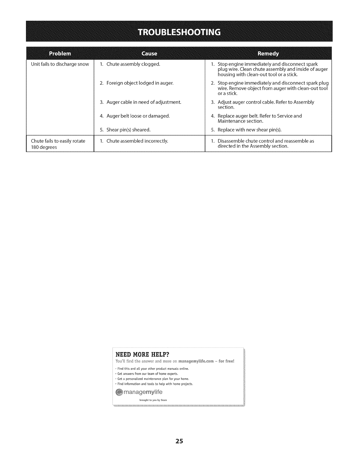
Unit fails to discharge snow
Chute fails to easily rotate
180 degrees
1. Chute assembly clogged. 1. Stop engine immediately and disconnect spark
2. Foreign object lodged in auger.
3. Auger cable in need of adjustment.
4. Auger belt loose or damaged.
5. Shearpin(s) sheared.
1. Chute assembled incorrectly.
plug wire. Clean chute assembly and inside of auger
housing with clean-out tool or a stick.
2. Stop engine immediately and disconnect spark plug
wire. Remove object from auger with clean-out tool
or a stick.
3. Adjust auger control cable. Refer to Assembly
section.
4. Replace auger belt. Refer to Service and
Maintenance section.
5. Replace with new shear pin(s).
1. Disassemble chute control and reassemble as
directed in the Assembly section.
NEED MORE HELP?
YotJU,fir_} the _: swe a_] :m,_"Yeo_:__._a_,a_emy[f_eo_@_,,,,,,,fo_' free!
o Find this and a[[ your other product manuals online.
Get answers from our team of home experts,
o Get a personalized maintenance plan for your home_
Find information and tools to help with home projects.
25
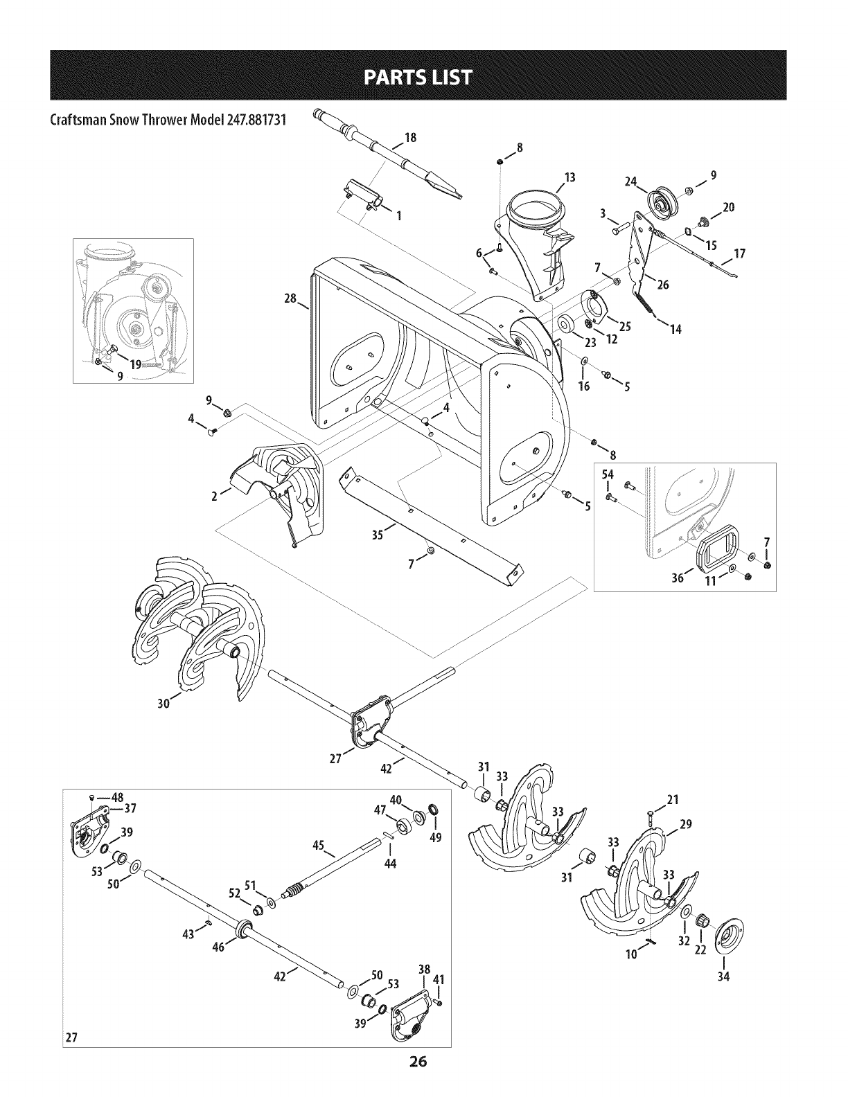
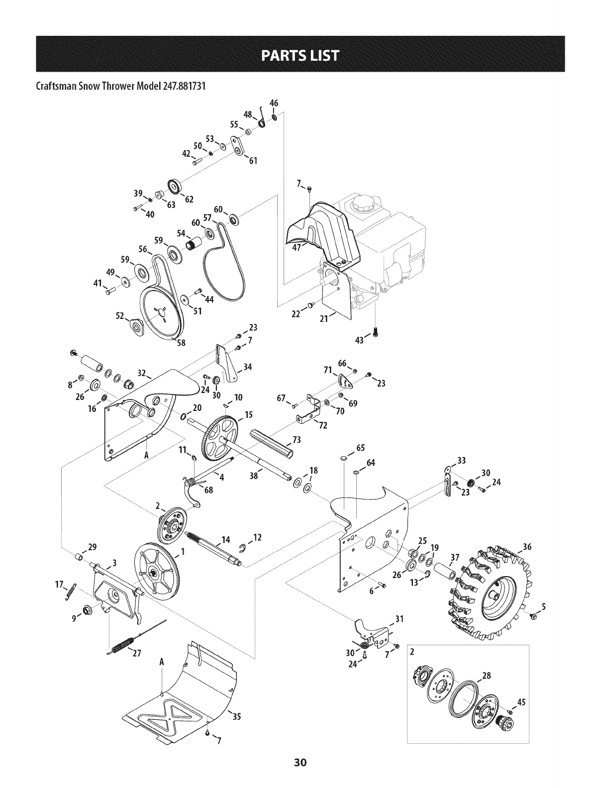
CraftsmanSnowThrowerModel 247.881731
18
/_\\/ 1
\\\\
8
o,/"
15 17
514 /
36/
i27
26
31
31
21
_"/ 29
J
33
I
34
Craftsman SnowThrowerModel 247.881731
m
1.
2.
3.
4.
5.
6.
7.
8.
9.
10.
11.
12.
13.
14.
15.
16.
17.
18.
19.
20.
21.
22.
23.
24.
25.
26.
27.
731-2635
684-04057A-0637
710-0347
710-0451
710-04484
710-0703
712-04063
712-04064
712-04065
714-04040
936-0159
926-04012
731-07525
732-04460
736-0174
736-0242
946-04230A
931-2643
738-0143
938-0281
738-04124A
941-0245
941-0309
756-04224
790-00075
790-00080A-0637
918- 04171B
Snow Removal Tool Mount
Impeller Assembly, 12" Dia.
Hex Screw, 3/8-16, 1.75, Gr5
Bolt, Carriage, 5/16-18, .750 Grl
Screw, 5/16-18, 0.750
Screw, Carriage, 1/4-20, .750, Gr5
Nut, Flange Lock, 5/16-18, Nylon
Nut, Flange Lock, 1/4-20, Nylon
Nut, Flange Lock, 3/8-16, Nylon
Cotter Pin, Bow-tie
Washer, Flat, .349 x .879 x .063
Nut, Push-on, .25 Dia
Chute, Adapter 5" Dia
Spring, Extension, .38 OD x 4.59
Washer, Wave, .625 x .885 x .015
Washer, Bell, .340 x .872 x .060
Clutch Cable, Auger, 47.23"
Snow Removal Tool
Screw, Shoulder, .498 x .34, 3/8-16
Screw, Shoulder, .625 x .17, 3/8-16
Shear Pin, .25 x 1.50
Bearing, Hex Flange x .75 ID
Bearing, Ball, .75 ID x 1.85 OD
Flat Pulley, Idler, 2.75 OD
Housing, Bearing, 1.85 ID
Bracket, Auger Idler w/Brake
Gearbox Assembly, Auger, 24"
M
28.
29.
30.
31.
32.
33.
34.
35.
36.
37.
38.
39.
40.
41.
42.
43.
44.
45.
46.
47.
48.
49.
50.
51.
52.
53.
54.
684-04265-4044
684-04107-0637
684-04108-0637
731-04870
736-0188
741-0493A
790-00087A-0637
790-00120-4044
731-06439
918-0123A
918-0124A
921-0338
741-0662
710-0642
711-04285
914-0161
715-04021
917-04126
917-04861
718-04071
721-0325
721-0327
936-0351
736-3084
741-0663
741-0661 B
710-0276
Housing Assembly, Auger 24"
Spiral Assembly, LH
Spiral Assembly, RH
Spacer, 1.25 OD x .75 ID x 1.00
Washer, Flat, .76 x 1.49 x .06
Bushing, Flange, .80 ID x .91 OD
Housing, I" Hex Bearing
Shave Plate, 2.25 x 23.66
Slide Shoe
Housing, Auger, RH Reduced
Housing, Auger, LH Reduced
Seal, Oil, .750 x 1.00 x .125
Bearing, Flange, .75 x 1.0 x .59
Screw, Self-tapping, I/4-20, 0.750
Axle, Auger, 24"
Key, Hi-pro 3/16 x 5/8
Pin, Dowel, .25 OD x 1.2
Shaft, Worm .75 OD
Gear, Worm 20T
Collar, Thrust
Plug, I/4 x .437
Seal, Oil, .75 x I x .131
Washer, Flat, .760 ID x 1.50D
Washer, Flat, .51 x 1.12
Bearing, Flange, .75 x 1.0 x .925
Bearing, Flange, .75 x 1.00 x .975
Screw, Carriage, 5/16-18 x 1.00
27
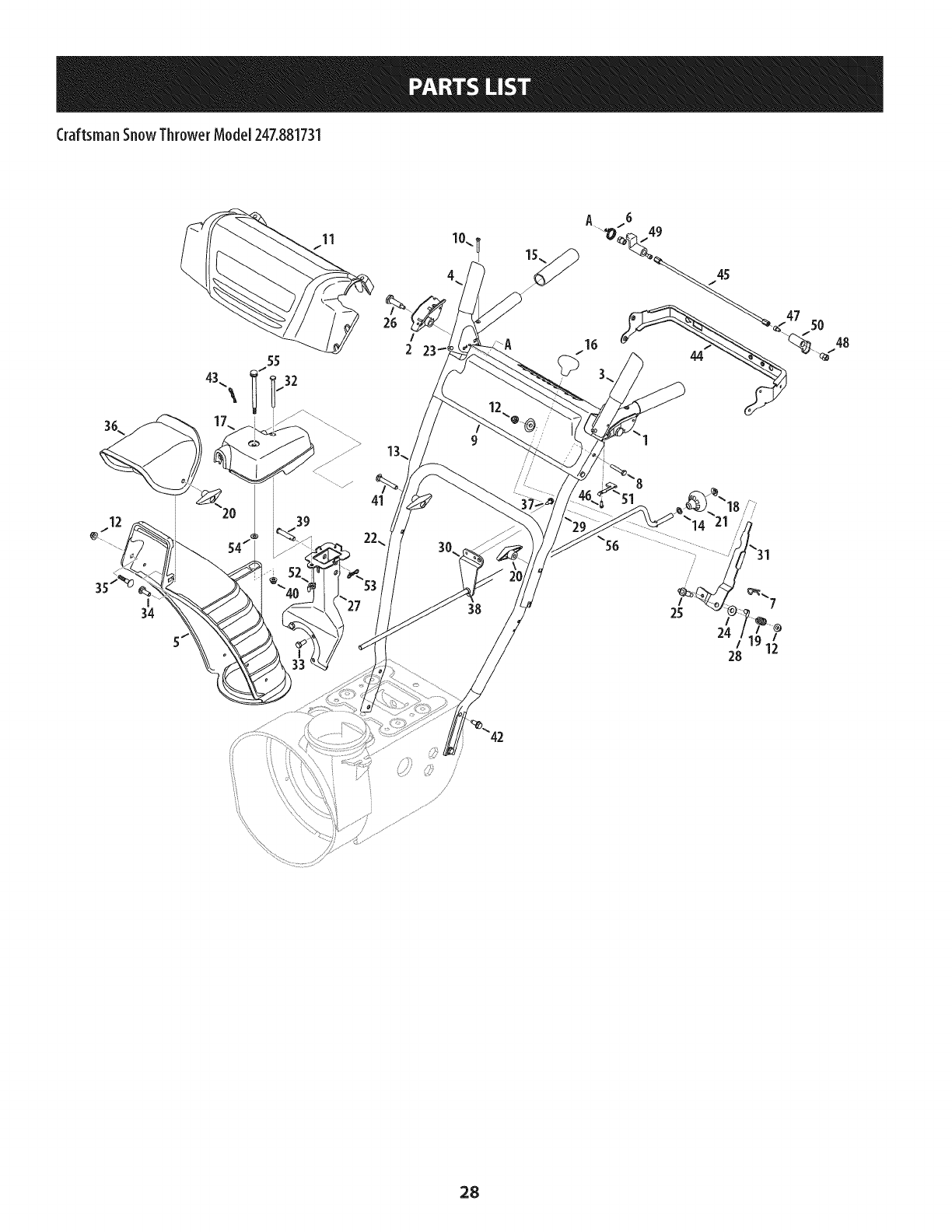
CraftsmanSnowThrowerModel 247.881731
A 6 49
I48
2A16 44
/
/
,/
/
24
28
28
CraftsmanSnowThrowerModel247.881731
m
1.
2.
3.
4.
5.
6.
7.
8.
9.
10.
11.
12.
13.
14.
15.
16.
17.
18.
19.
20.
21.
22.
23.
24.
25.
26.
27.
28.
29.
631 -04133A
631-04134B
684- 04111 B
684-04112C
731-06440A
732-04238
914-0145
710-04586
790-00219-4044
710-1233
731-06471
712-04063
749-04190A-0637
936-0185
720-0274
720-04039
918-04933
926-0100
732-0193
920-0284
720-04102
749-04138B-0637
935-0199A
736-0262
738-04118
738-04348
684-04311A-0637
946-04397A
749-04191A-0637
Handle Assembly, Clutch Lock, LH
Handle Assembly, Clutch Lock, RH
Handle Ass'y, Engage, LH
Handle Ass'y, Engage, RH
Chute, Lower
Spring, Torsion, .8156 ID x .3038
Click Pin
Screw, 1/4-20 x 1.625
Panel, Handle, (no cutout)
Screw, Machine, #10-24, 1.375
Handle Panel Cover
Nut, Flange Lock, 5/16-18, Nylon
Handle, Upper, RH
Washer, Flat, .375 x .738 x .063
Grip, 1.0 ID x 5.0
Knob, Shift, Black
Gearbox Assembly
Cap, Push, 3/8 Rod
Spring, .39 x .60 x .88
Knob, 5/16-18, Black
Crank Knob
Handle, Lower
Bumper, Rubber, .62 OD x .22
Washer, Flat, .385 x .870 x .092
Bolt, Shoulder, 5/16-18 x 0.905
Screw, Shoulder, .43 x 1.3, 1/4-20
Bracket, Chute Support
Cable, Speed Selector
Handle, Upper, LH
m
m
30.
31.
32.
33.
34.
35.
36.
37.
38.
39.
40.
41.
42.
43.
44.
45.
46.
47.
48.
49.
50.
51.
52.
53.
54.
55.
56.
790-00341-0637
790-00313-0637
710-04370
710-0627
710-04071
710-0451
731-04426A
710-1652
941-0475
711-04469A
712-04064
710-0572
710-04484
914-0101
790-00248C-0637
684-04250
710-04326
710-3069
712-04081A
731-04894D
731-04896B
Bracket, Rod
Shift Lever
Screw, 1/4-20 x 3.00
Screw, 5/16-24 x .750
Bolt, Carriage, 5/16-18, 1.0
Bolt, Carriage, 5/16-18, .750
Chute, Upper, w/Label
Screw, 1/4-20 x .625
Bushing, Plastic, .380
Pin, Clevis
Nut, Flange Lock, 1/4-20
Screw, Carriage, 5/16-18, 2.25
Screw, 5/16-18, 2.25, Gr5
Pin, Cotter
Bracket, Panel
Rod, Pivot
Screw, #8-16 x .50
Screw, 1/4-20 x .50
Nut, Hex, 1/4-20
Plate, Lock
Cam, Clutch Lock
732-04219C
712-3087
714-04040
736-04446
738-04367
747-05386-0637
753-08018±
Spring, Clutch Lock
Nut, Wing
Bow-Tie Cotter Pin
Washer, Flat, .25 x .630 x .0515
Scr. Shldr. Fig., .312 x 3.5 x 1/4-20
Crank, Chute
Chute Kit (Incl. Ref.# 5 & 36)
± Available for warranty coverage only. Contact a Sears authorized
service provider for details.
29
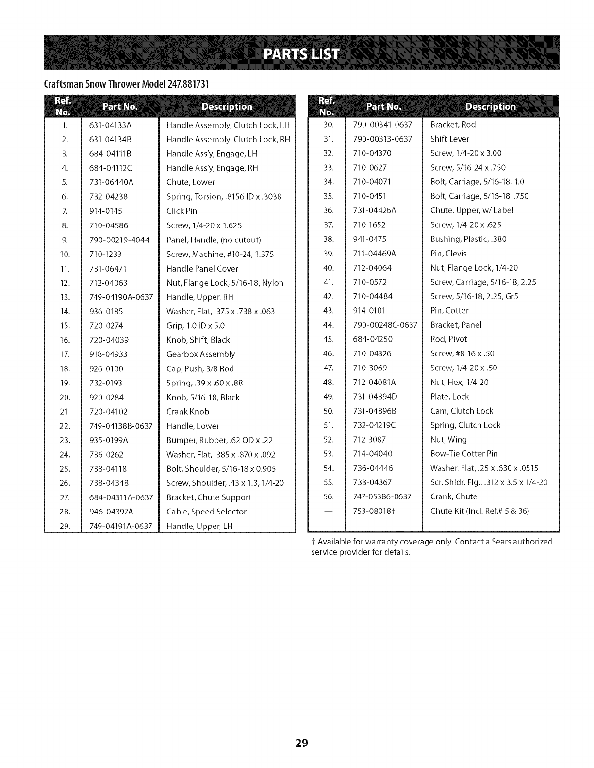
CraftsmanSnowThrowerModel247.881731
46
41,
/23
7
34
I
30 10
15
38
73
17
3O
Craftsman SnowThrowerModel 247.881731
I.
2.
3.
4.
5.
6.
7.
8.
9.
10.
11.
12.
13.
14.
15.
16.
17.
18.
19.
20.
21.
22.
23.
24.
25.
26.
27.
28.
29.
30.
31.
32.
33.
34.
35.
36.
37.
656-04055
684-04153C
684-04154B-0637
684- 04156A
710-05339
710-0788
710-1652
712-04065
712-0417A
914-0126
916-0104
716-0136
916-0231
917-04209A
917-04230
726-0221
932-0264
736-0188
936-0287
736-04161
790-00289A-0637
738-04439
738-04184A
738-0924A
941-0245
941-0563
946-05067
935-04054
748-0190
756-0625
790-00096A-0637
790-00180C-4044
790-00206A-0637
790-00207C
790-00316-4044
634-04167A-0911
634-04168A-0911
731-04873
Disc Assembly, Friction Wheel
Friction Wheel Assembly, 5.50D
Support Bracket, Friction Wheel
Shift Assembly, Rod
Screw, 5/16-24, .750, Gr5
Screw, 1/4-20, 1.000
Screw, 1/4-20 x .625
Nut, Flange Lock, 3/8-16, Nylon
Nut, Flange, 5/8-18
Key, Hi Pro, 3/16 x 3/4 Dia.
E-ring, .500 Dia.
E-ring, Retaining, .875 Dia.
E-ring, .750 Dia.
Hex Shaft, .8125, 7-Tooth
Gear, 80-Tooth
Speed Nut, .500
Extension Spring
Washer, Flat, .760 x 1.490 x .060
Washer, Flat, .793 x 1.24 x .060
Washer, Flat, .75 x 1.00 x .060
Plate, Cover
Shoulder Screw
Screw, Shoulder, .37 x .105, 1/4-20
Screw, 1/4-28, .375
Bearing, Hex Flange x .75 ID
Bearing, Ball, 17 x 40 x 12
Clutch Cable, Wheel, 44.95"
Rubber, Friction Wheel, 5.50D
Spacer, .508 ID x .75 OD x .68
Roller, Cable
Front Guide Bracket, Auger Cable
Frame
Guide Bracket, Auger Cable
Guide Bracket, Drive Cable
Cover, Frame
LH Wheel Assembly
RH Wheel Assembly
Spacer, 1.25 x .75 x 3.0
m
m
38.
39.
40.
41.
42.
43.
44.
45.
46.
47.
48.
49.
50.
51.
52.
53.
54.
55.
56.
57.
58.
59.
60.
61.
62.
63.
64.
65.
66.
67.
68.
69.
70.
71.
72.
73.
N/A
738-04493
936-0329
710-0809
710-0191
710-0672
710-0654A
710-1245B
710-04484
926-04012
731-05353
732-04308A
736-3082A
936-0119
736-0505
748-04053A
748-04112B
750-04303
750-04477A
954-04050
954-04260
756-04109
756-04113
756-04252
790-00208D
684-04169
750-04571
735-04099
735-04100
712-04064
710-0751
732-04311A
712-04063
936-3015
Axle, .75 x 22"
Washer, Lock, 1/4
Hex Screw, 1/4-20, 1.25, Gr5
Hex Screw, 3/8-24, 1.25, Gr8
Hex Screw, 5/16-24, 1.25, Gr5
Screw, Seres, 3/8-16, 1.00
Hex Screw, 5/16-24, .875, Gr8
Screw, 5/16-18 x .750
Nut, Push-on, .25 Dia.
Cover, Belt
Spring, Torsion, .850 ID x .354
Washer, Flat, .45 x 1.5 x .172
Washer, Lock .3125
Washer, Flat, .34 x 1.50 x .150
Pulley, Adapter, .75 Dia.
Spacer, Shoulder, .317 x .50 x .102
Spacer, .875 ID x 1.185 OD
Spacer, .340 x .750 x .360
Belt, Auger Drive
Belt, Wheel Drive
Pulley, Auger Drive, 8.1 x .5
Pulley, Half, V x 2.600 OD
Pulley, Half, 3/8-V x 1.7160 OD
Idler Bracket, Wheel Drive
Idler Pulley Assembly
Spacer, Shoulder, .26 x .79 x .538
Plug, 3/8 ID
Plug, 1/2 ID
Nut, Flange Lock, 1/4-20, Nylon
Hex Screw, 1/4-20, .620, Gr5
Spring, Torsion, .750 ID x .968
Nut, Flange Lock, 5/16-18, Nylon
Wash., Flat, .469 x .875 x .105
790-00217A-0637
790-00218A-0637
731-08181
Pivot Bracket, Speed Selector
Shift Bracket, Speed Selector
Spacer, Axle
Engine (see breakdown)
MTD Model No. 952Z270-SUA
31
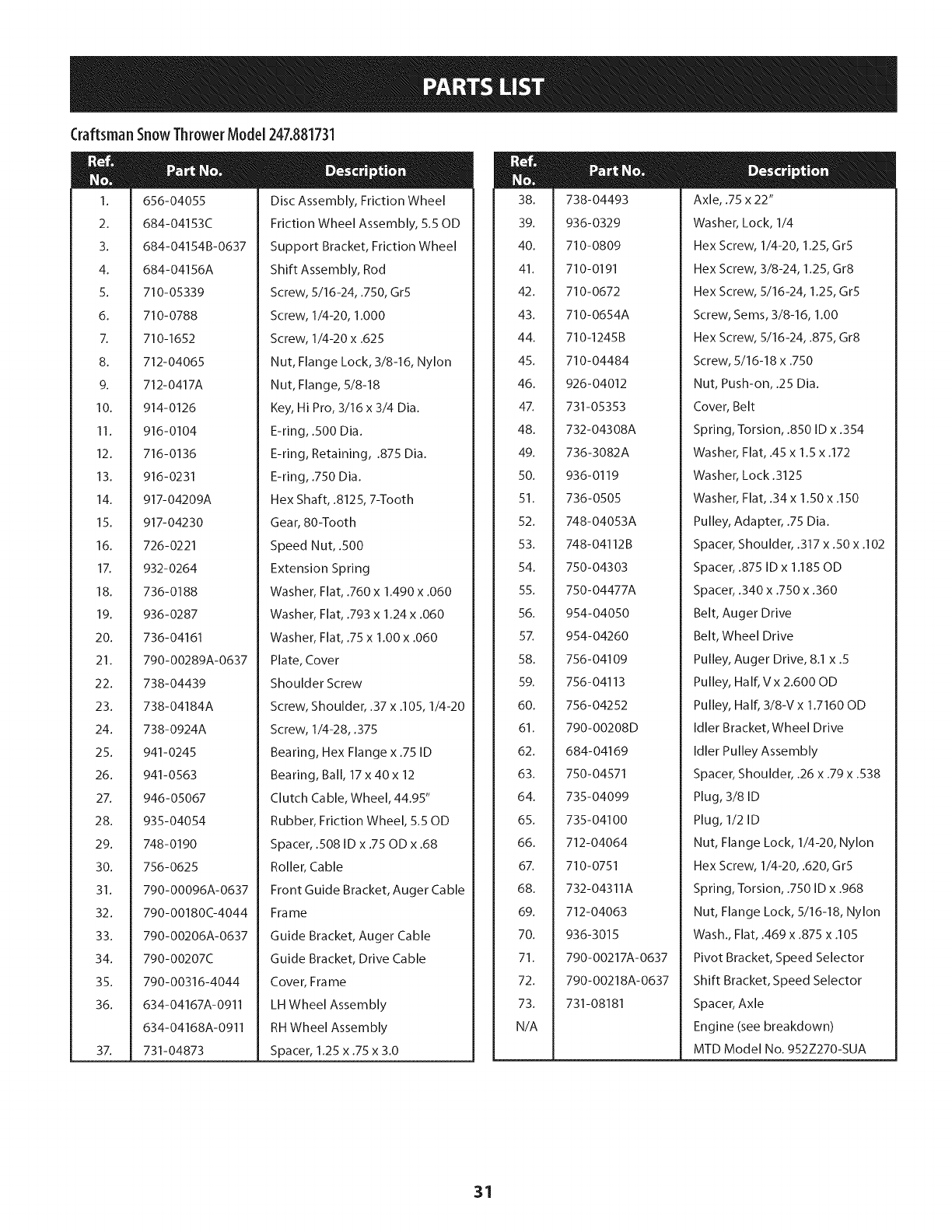
CraftsmanEngineModel270-SUAForSnowModel247.881731
24
23
23
221
19
20
20
21
22
23
24
951-11282
710-05001
951-14190
951-11289
712-04214
710-04915
951-10642B
D _ o ii
Muffler Assembly
Muffler Stud
Muffler Stud Kit
Muffler Gasket
Nut- M8
Bolt - M6 X 12 Zin
Muffler Shroud
32
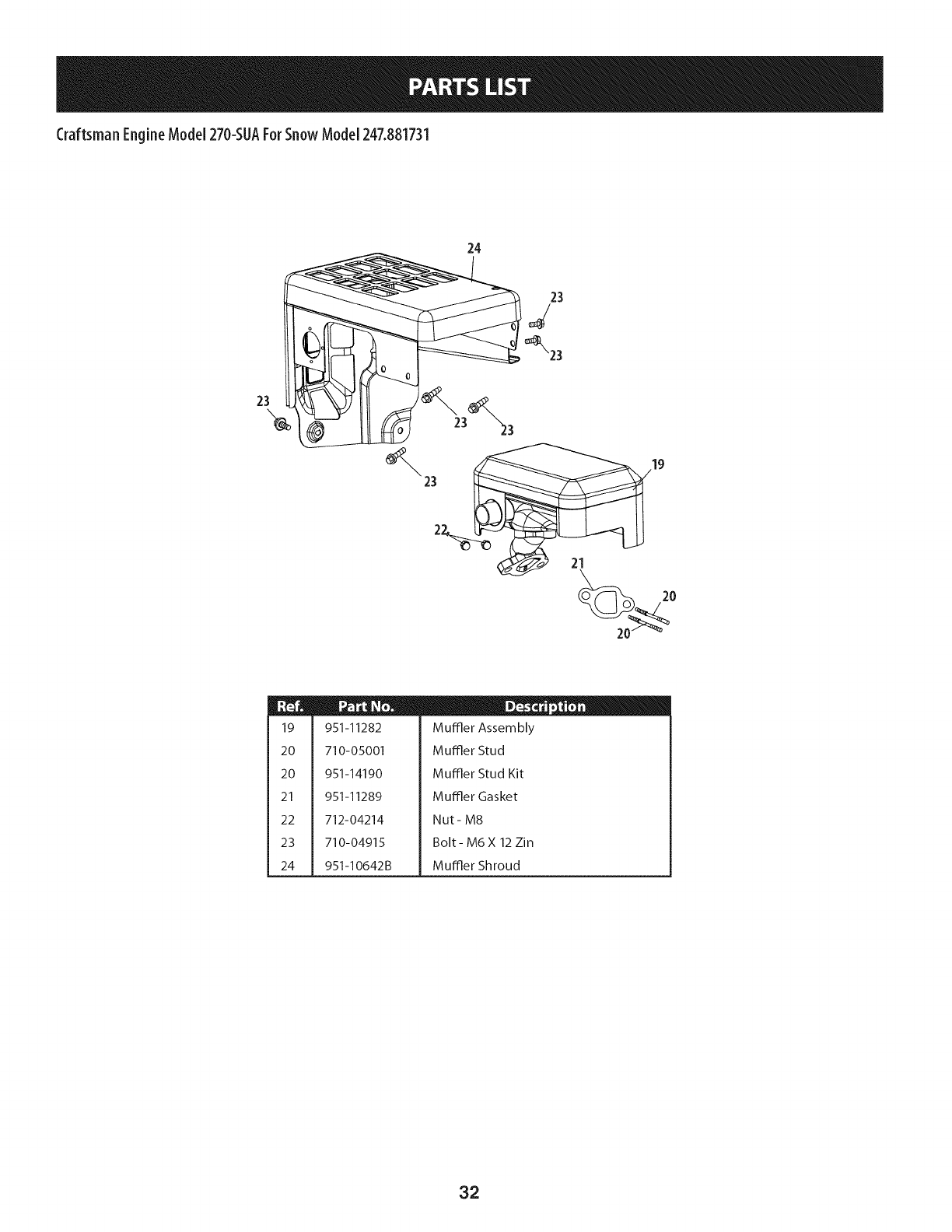
Craftsman EngineModel270-SUAForSnowModel247.881731
41 _42
°0 37
35
34
35
36
37
39
4O
41
42
43
951-10634
712-04213
951-11284
951-10757
951-10637
731-05632
951-10640
951-10635
710-04943
D _ o o
Shroud-Engine
Nut
Choke Knob
Throttle Knob
Switch-Ignition
Ignition Key Switch
Push Rod-Choke
Air Filter Heating
Bolt-M6 1X28M Spec
33
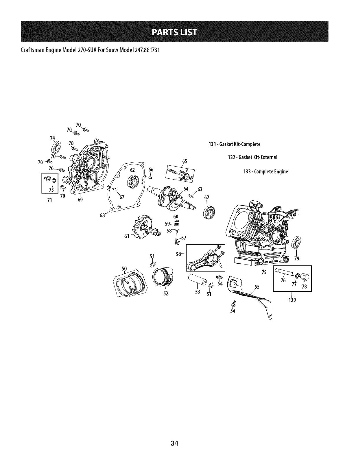
Craftsman EngineModel270-SUAForSnowModel247.881731
131-GasketKit-Complete
132-GasketKit-External
133- CompleteEngine
34
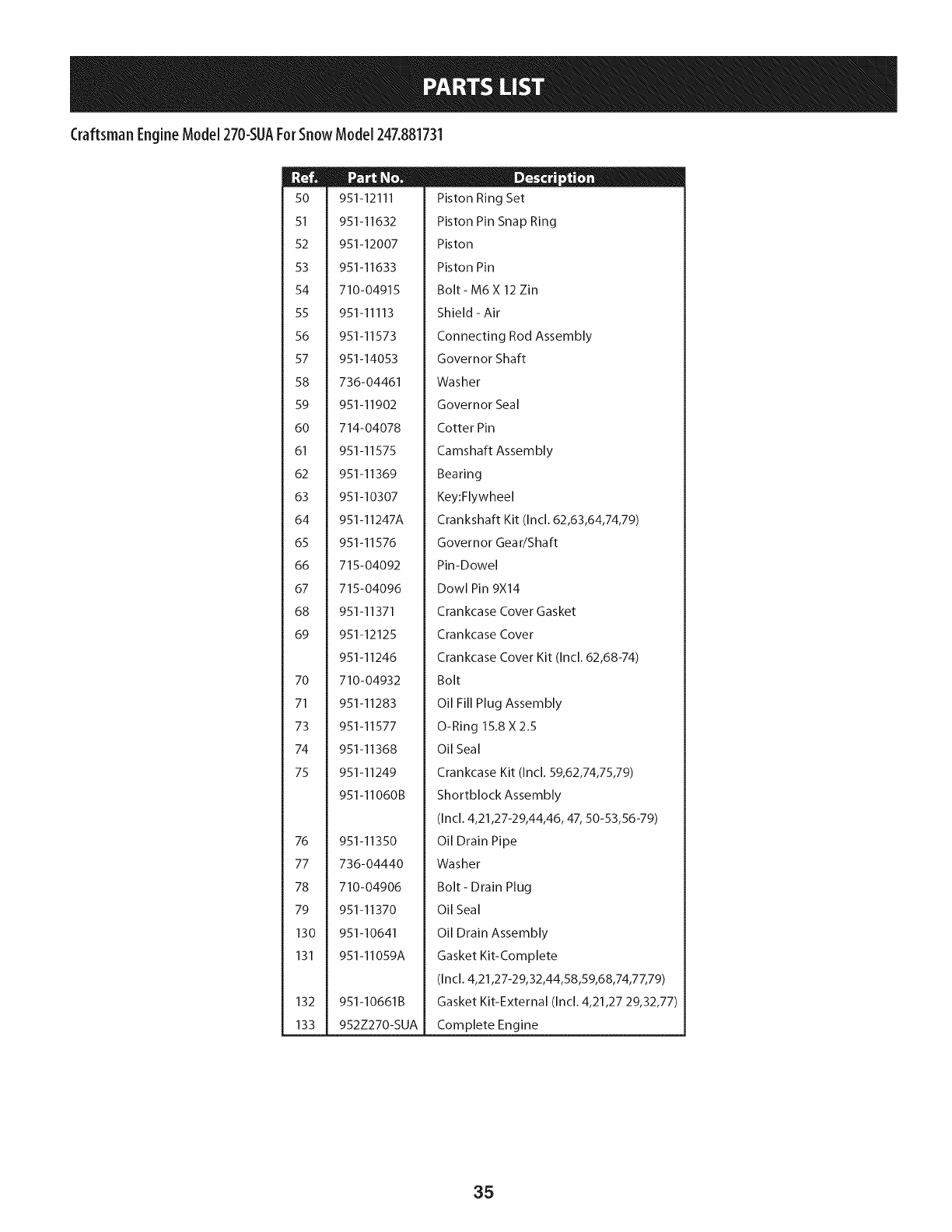
Craftsman EngineModel270-SUAForSnowModel247.881731
50
51
52
53
54
55
56
57
58
59
60
61
62
63
64
65
66
67
68
69
70
71
73
74
75
76
77
78
79
130
131
132
133
951-12111
951-11632
951-12007
951-11633
710-04915
951-11113
951-11573
951-14053
736-04461
951-11902
714-04078
951-11575
951-11369
951-10307
951-11247A
951-11576
715-04092
715-04096
951-11371
951-12125
951-11246
710-04932
951-11283
951-11577
951-11368
951-11249
951-11060B
951-11350
736-04440
710-04906
951-11370
951-10641
951-11059A
951-10661B
952Z270-SUA
D _ o 0
Piston Ring Set
Piston Pin Snap Ring
Piston
Piston Pin
Bolt- M6 X 12 Zin
Shield - Air
Connecting Rod Assembly
Governor Shaft
Washer
Governor Seal
Cotter Pin
Camshaft Assembly
Bearing
Key:Flywheel
Crankshaft Kit (Incl. 62,63,64,74,79)
Governor Gear/Shaft
Pin-Dowel
Dowl Pin 9X14
Crankcase Cover Gasket
Crankcase Cover
Crankcase Cover Kit (Incl. 62,68-74)
Bolt
Oil Fill Plug Assembly
O-Ring 15.8 X2.5
Oil Seal
Crankcase Kit (Incl. 59,62,74,75,79)
Shortblock Assembly
(Incl. 4,21,27-29,44,46, 47, 50-53,56-79)
Oil Drain Pipe
Washer
Bolt- Drain Plug
Oil Seal
Oil Drain Assembly
Gasket Kit-Complete
(Incl. 4,21,27-29,32,44,58,59,68,74,77,79)
Gasket Kit-External (Incl. 4,21,27 29,32,77)
Complete Engine
35
Craftsman EngineModel270-SUAForSnowModel247.881731
129
15
13
18
17
44 _p 49 46 _46
_ U" -"45
131- GasketKit-Complete
132-GasketKit-External
133- CompleteEngine
36
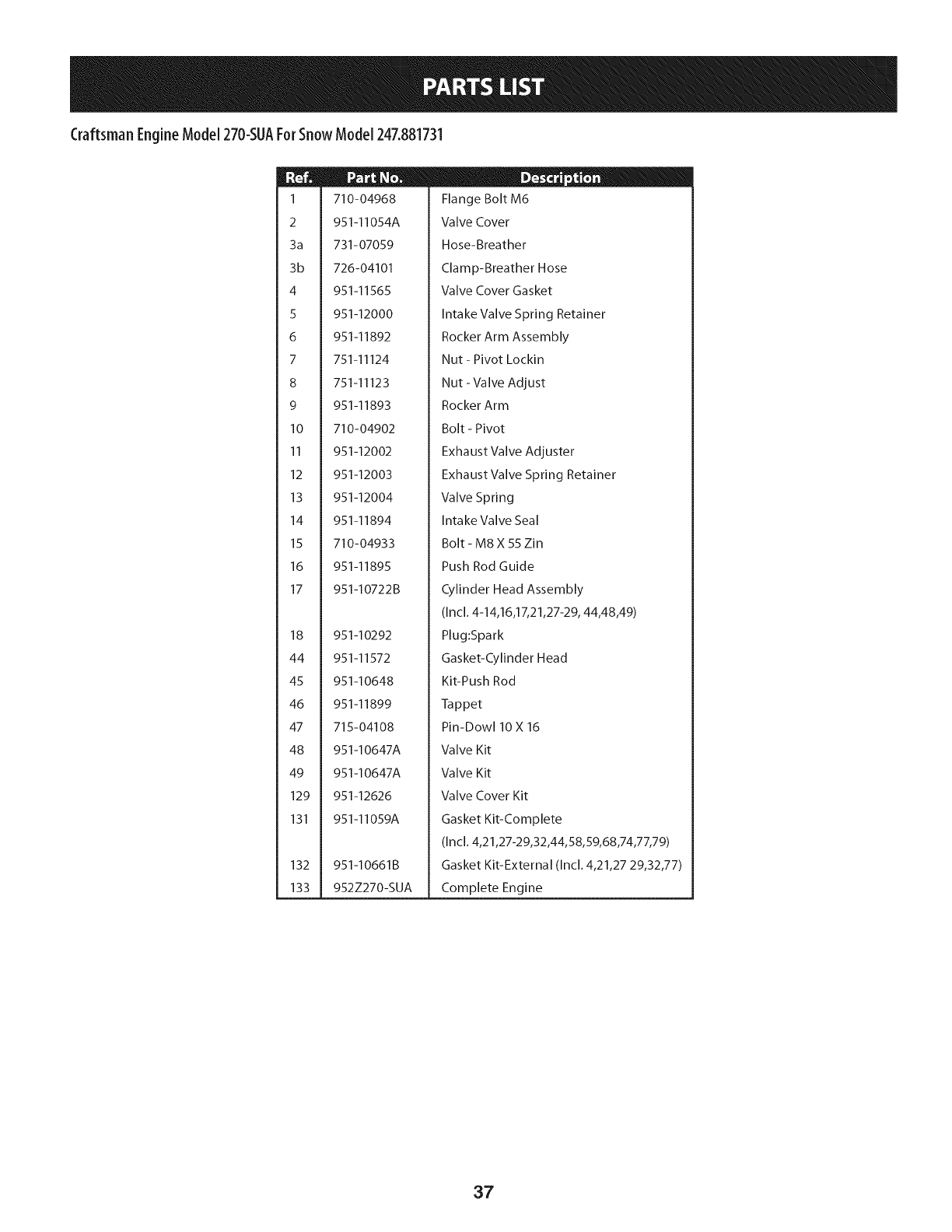
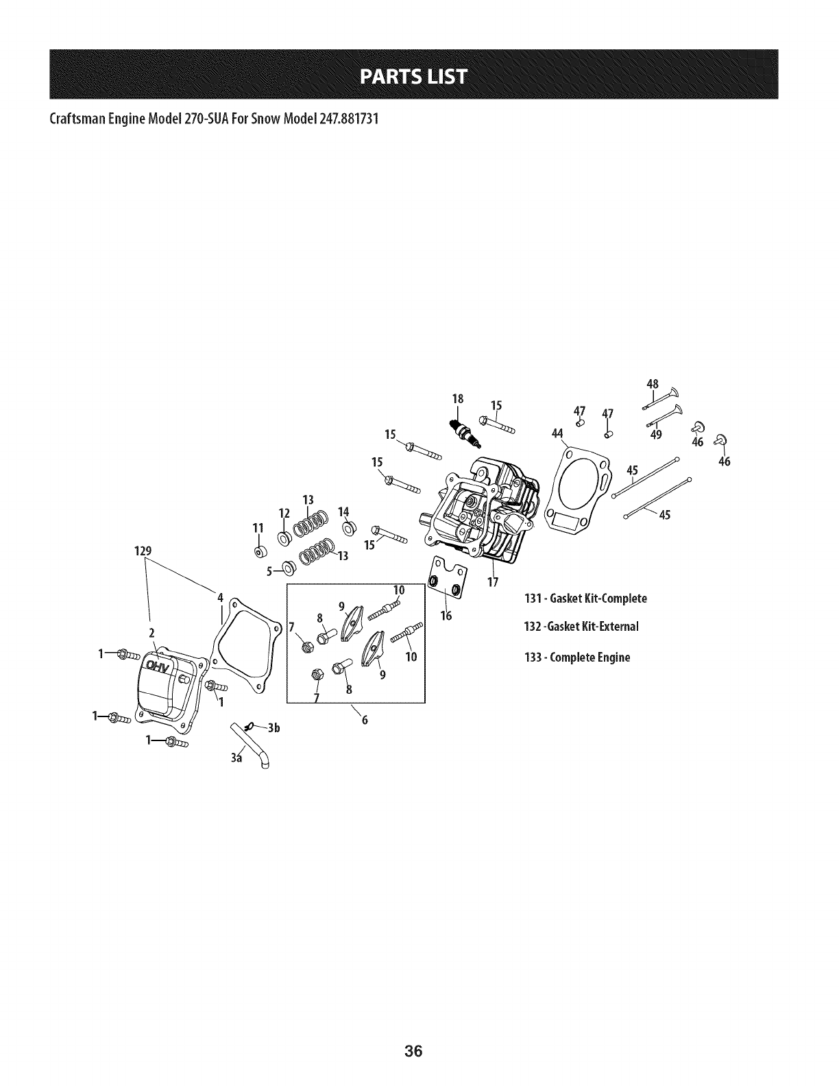
Craftsman EngineModel270-SUAForSnowModel247.881731
1
2
3a
3b
4
5
6
7
8
9
10
11
12
13
14
15
16
17
18
44
45
46
47
48
49
129
131
132
133
710-04968
951-11054A
731-07059
726-04101
951-11565
951-12000
951-11892
751-11124
751-11123
951-11893
710-04902
951-12002
951-12003
951-12004
951-11894
710-04933
951-11895
951-10722B
951-10292
951-11572
951-10648
951-11899
715-04108
951-10647A
951-10647A
951-12626
951-11059A
951-10661B
952Z270-SUA
ID -o 0
Flange Bolt M6
Valve Cover
Hose-Breather
Clamp-Breather Hose
Valve Cover Gasket
Intake Valve Spring Retainer
Rocker Arm Assembly
Nut - Pivot Lockin
Nut - Valve Adjust
Rocker Arm
Bolt - Pivot
Exhaust Valve Adjuster
Exhaust Valve Spring Retainer
Valve Spring
Intake Valve Seal
Bolt - M8 X 55 Zin
Push Rod Guide
Cylinder Head Assembly
(Incl. 4-14,16,17,21,27-29, 44,48,49)
Plug:Spark
Gasket-Cylinder Head
Kit-Push Rod
Tappet
Pin-Dow110 X 16
Valve Kit
Valve Kit
Valve Cover Kit
Gasket Kit-Complete
(Incl. 4,21,27-29,32,44,58,59,68,74,77,79)
Gasket Kit-External (Incl. 4,21,27 29,32,77)
Complete Engine
37
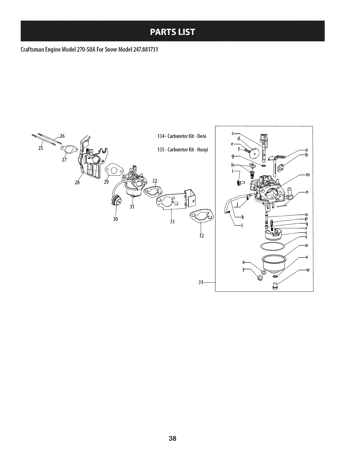
CraftsmanEngineModel270-SUAForSnowModel247.881731
27
28
3O
134- CarburetorKit- Deni
135-CarburetorKit- Huayi
31_
w
38
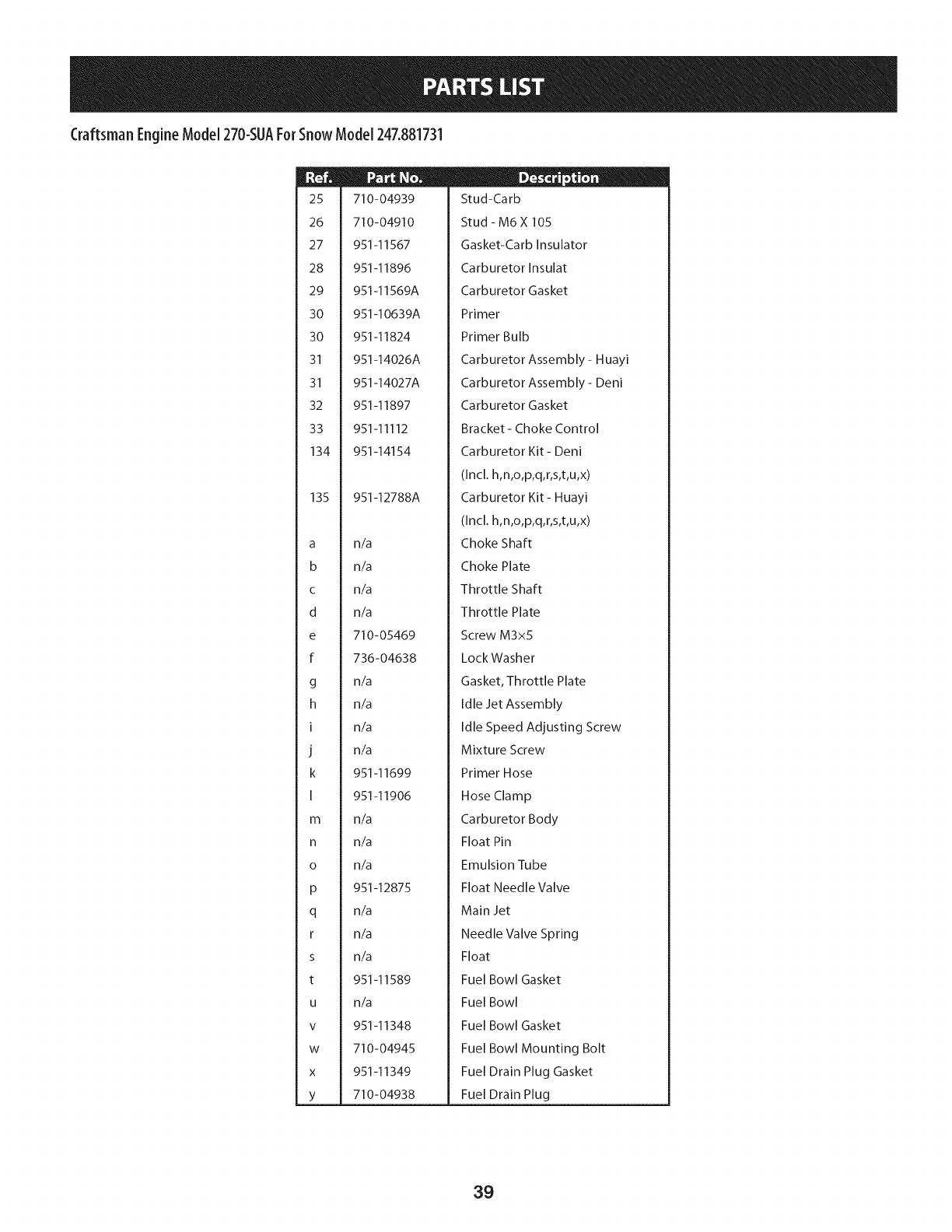
Craftsman EngineModel270-SUAForSnowModel247.881731
25
26
27
28
29
30
30
31
31
32
33
134
135
a
b
C
d
e
f
g
h
I
J
k
I
m
n
o
P
q
r
s
t
U
V
W
X
Y
710-04939
710-04910
951-11567
951-11896
951-11569A
951-10639A
951-11824
951-14026A
951-14027A
951-11897
951-11112
951-14154
951-12788A
n/a
n/a
n/a
n/a
710-05469
736-04638
n/a
n/a
n/a
n/a
951-11699
951-11906
n/a
n/a
n/a
951-12875
n/a
n/a
n/a
951-11589
n/a
951-11348
710-04945
951-11349
710-04938
II _ o w
Stud-Carb
Stud- M6X 105
Gasket-Carb Insulator
Carburetor Insulat
Carburetor Gasket
Primer
Primer Bulb
Carburetor Assembly - Huayi
Carburetor Assembly - Deni
Carburetor Gasket
Bracket- Choke Control
Carburetor Kit- Deni
(Incl. h,n,o,p,q,r,s,t,u,x)
Carburetor Kit- Huayi
(Incl. h,n,o,p,q,r,s,t,u,x)
Choke Shaft
Choke Plate
Throttle Shaft
Throttle Plate
Screw M3x5
LockWasher
Gasket, Throttle Plate
Idle Jet Assembly
Idle Speed Adjusting Screw
Mixture Screw
Primer Hose
Hose Clamp
Carburetor Body
Float Pin
Emulsion Tube
Float Needle Valve
Main Jet
Needle Valve Spring
Float
Fuel Bowl Gasket
Fuel Bowl
Fuel Bowl Gasket
Fuel Bowl Mounting Bolt
Fuel Drain Plug Gasket
Fuel Drain Plug
39
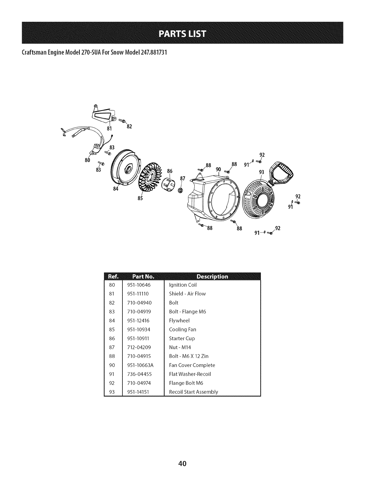
Craftsman EngineModel270-SUAForSnowModel247.881731
82
84
85 92
8O
81
82
83
84
85
86
87
88
9O
91
92
93
951-10646
951-11110
710-04940
710-04919
951-12416
951-10934
951-10911
712-04209
710-04915
951-10663A
736-04455
710-04974
951-14151
Ignition Coil
Shield - Air Flow
Bolt
Bolt - Flange M6
Flywheel
Cooling Fan
Starter Cup
Nut- M14
Bolt- M6X 12 Zin
Fan Cover Complete
Flat Washer-Recoil
Flange Bolt M6
Recoil Start Assembly
4O
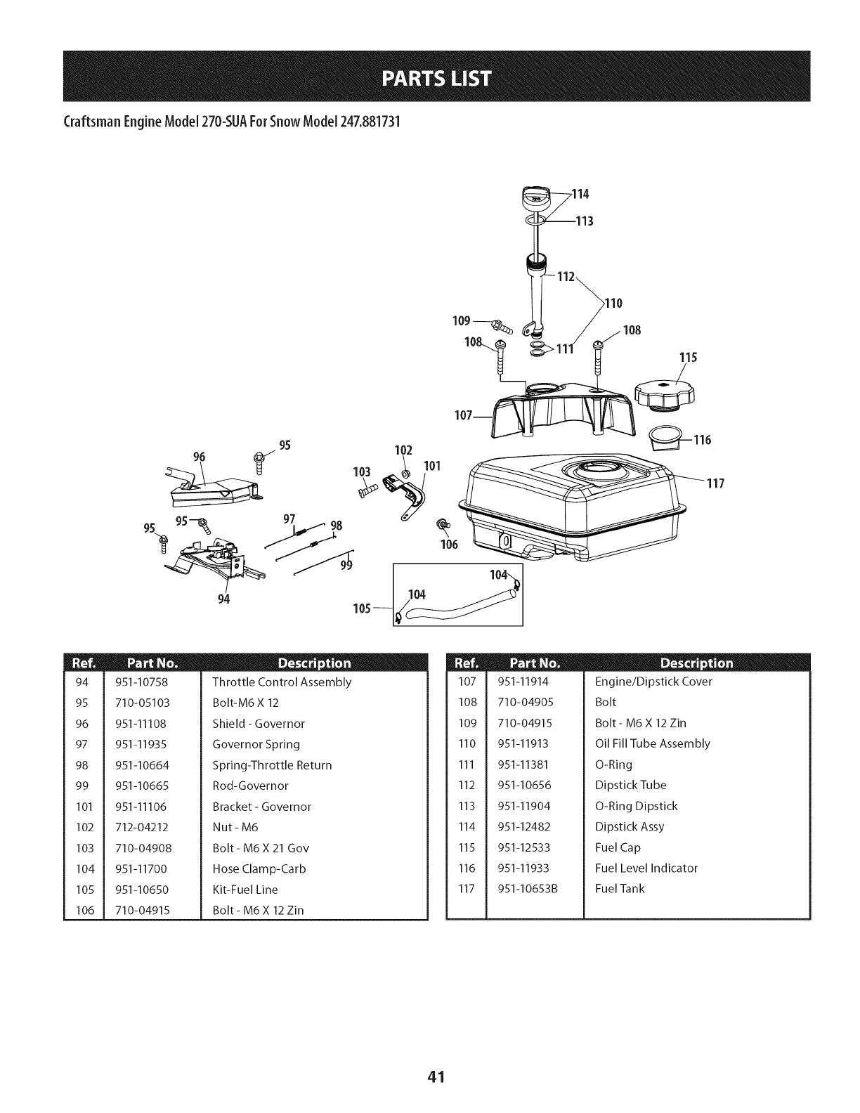
Craftsman EngineModel270-SUAForSnowModel247.881731
,114
115
94 105 104
94
95
96
97
98
99
101
102
103
104
105
106
951-10758
710-05103
951-I 1108
951-I 1935
951-10664
951-I0665
951 -l I 106
712-04212
710-04908
951-I1700
951-I0650
710-04915
D - o o
Throttle Control Assembly
Bolt-M6 X 12
Shield - Governor
Governor Spring
Spring-Throttle Return
Rod-Governor
Bracket- Governor
Nut- M6
Bolt - M6 X 21 Gov
Hose Clamp-Carb
Kit-Fuel Line
Bolt - M6 X 12 Zin
107
108
109
110
111
112
113
114
115
116
117
951-11914
710-04905
710-04915
951-11913
951-11381
951-10656
951-11904
951-12482
951-12533
951-11933
951-10653B
D - o
Engine/Dipstick Cover
Bolt
Bolt- M6 X 12 Zin
Oil Fill Tube Assembly
O-Ring
Dipstick Tube
O-Ring Dipstick
Dipstick Assy
Fuel Cap
Fuel Level Indicator
Fuel Tank
41
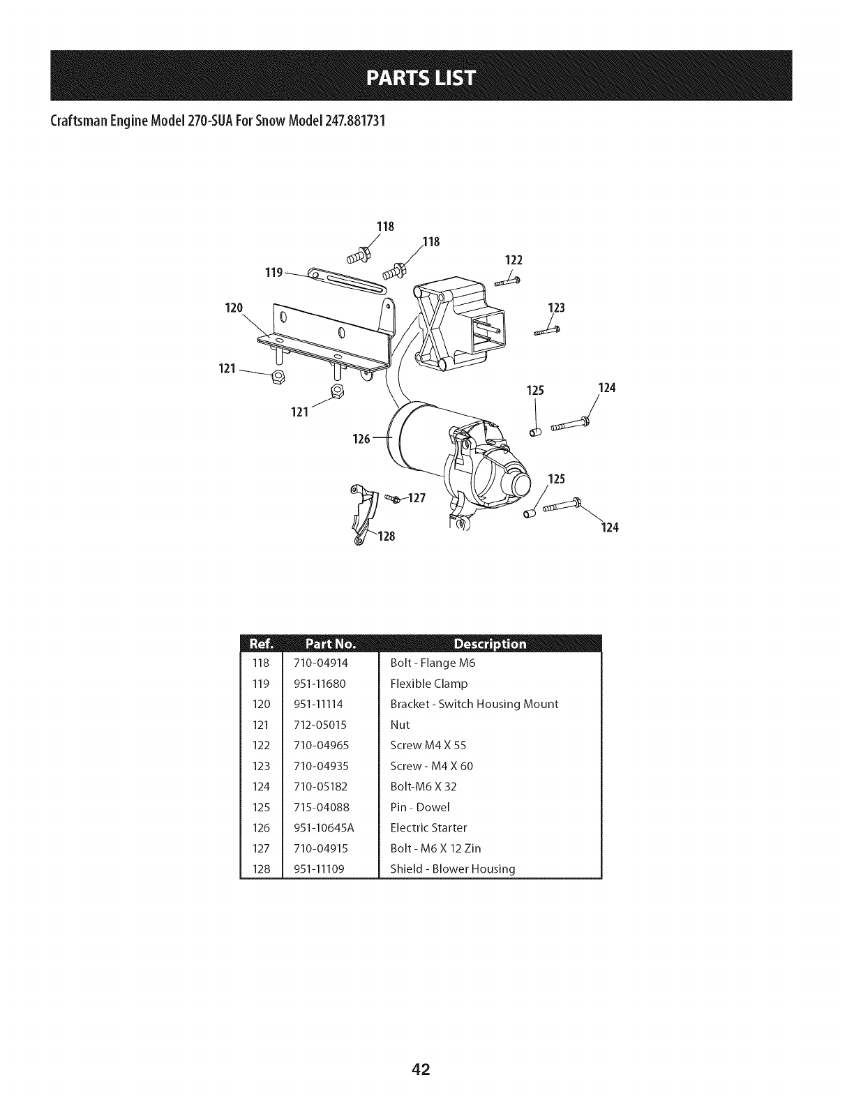
Craftsman EngineModel270-SUAForSnowModel247.881731
120
118
119
123
121
121
1_127
28 124
m
118
119
120
121
122
123
124
125
126
127
128
710-04914
951-11680
951-11114
712-05015
710-04965
710-04935
710-05182
715-04088
951-I0645A
710-04915
951-11109
D - o e
Bolt- Flange M6
Flexible Clamp
Bracket- Switch Housing Mount
Nut
Screw M4 X 55
Screw - M4 X 60
Bolt-M6 X 32
Pin - Dowel
Electric Starter
Bolt- M6X 12 Zin
Shield - Blower Housing
42
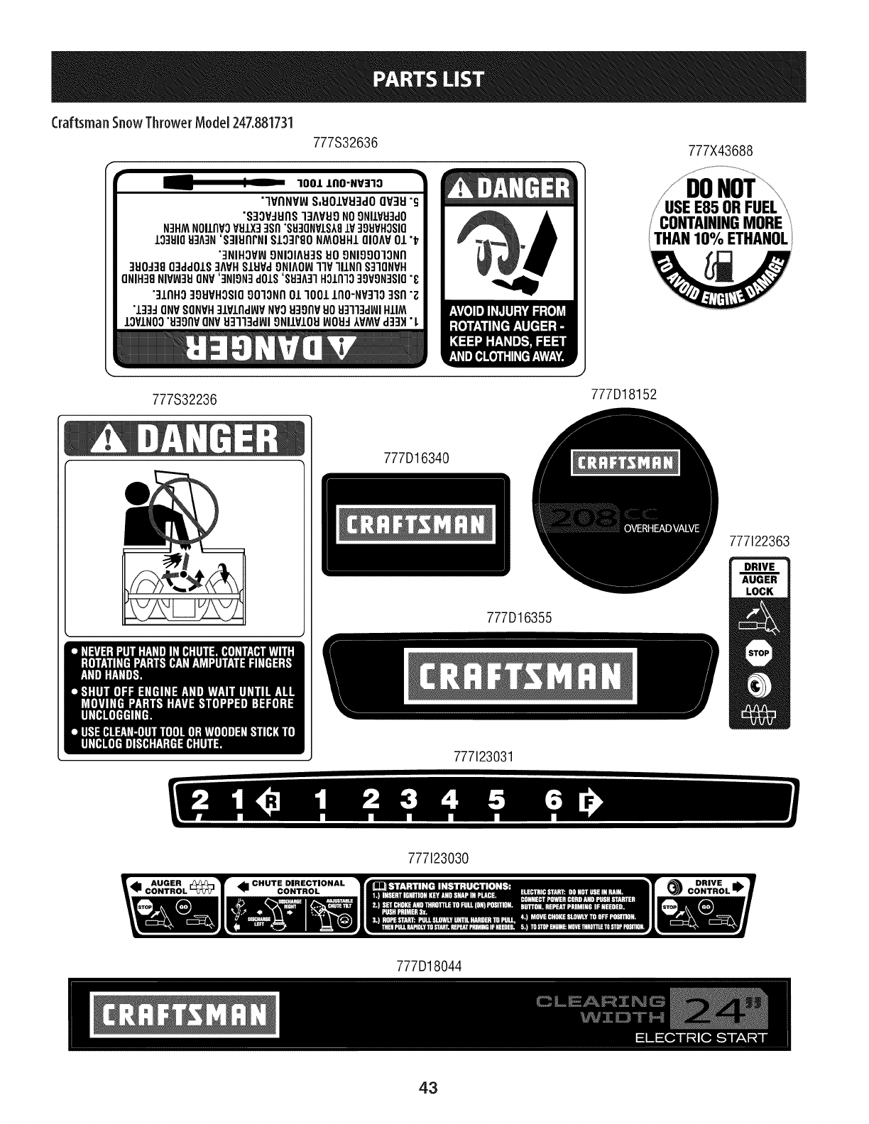
Craftsman SnowThrowerModel247.881731
777S32636
100/.I, IIO-NV=IIO
"lVflNVlAIS,EIOIVEI3dOQV:IEI"g
"S:IOV:IEII1S"13MEI9NO9NIIVEI3dO
N3HMNOIlflVOVUIX3]Sfl"SU3QN¥1S_8IV 39UVHO$10
IO]UIOH]A3N'S]IUflFNI $133r80 NMOHHIOlOAV01 "_
"3NIHOV_9NIOIAU3SUO9NIOOO13Nfl
3UO_3BO3ddOIS3MH SIUVd9NIAOW11VlllNfl S]IONVH
ONIH38NIV_3UONV'3NIgN3dOIS'$83A31HOLfllO39VgN3SIO"_
"31flHO399VHOSIO901ONflO11001lflO'NV310 3sn "_
•133:10NVSONVH31VlfldWVNV3U39flVUOU3113dWIHIlM
IOVINO3"EI:IOflVONVU:rl"lqd_l ONIIVIOEII_OEI-IIVMV d:l:l)l"L
777X43688
777S32236
J
777D18152
777D16340
777122363
777D16355
777123031
777123030
777D18044
43
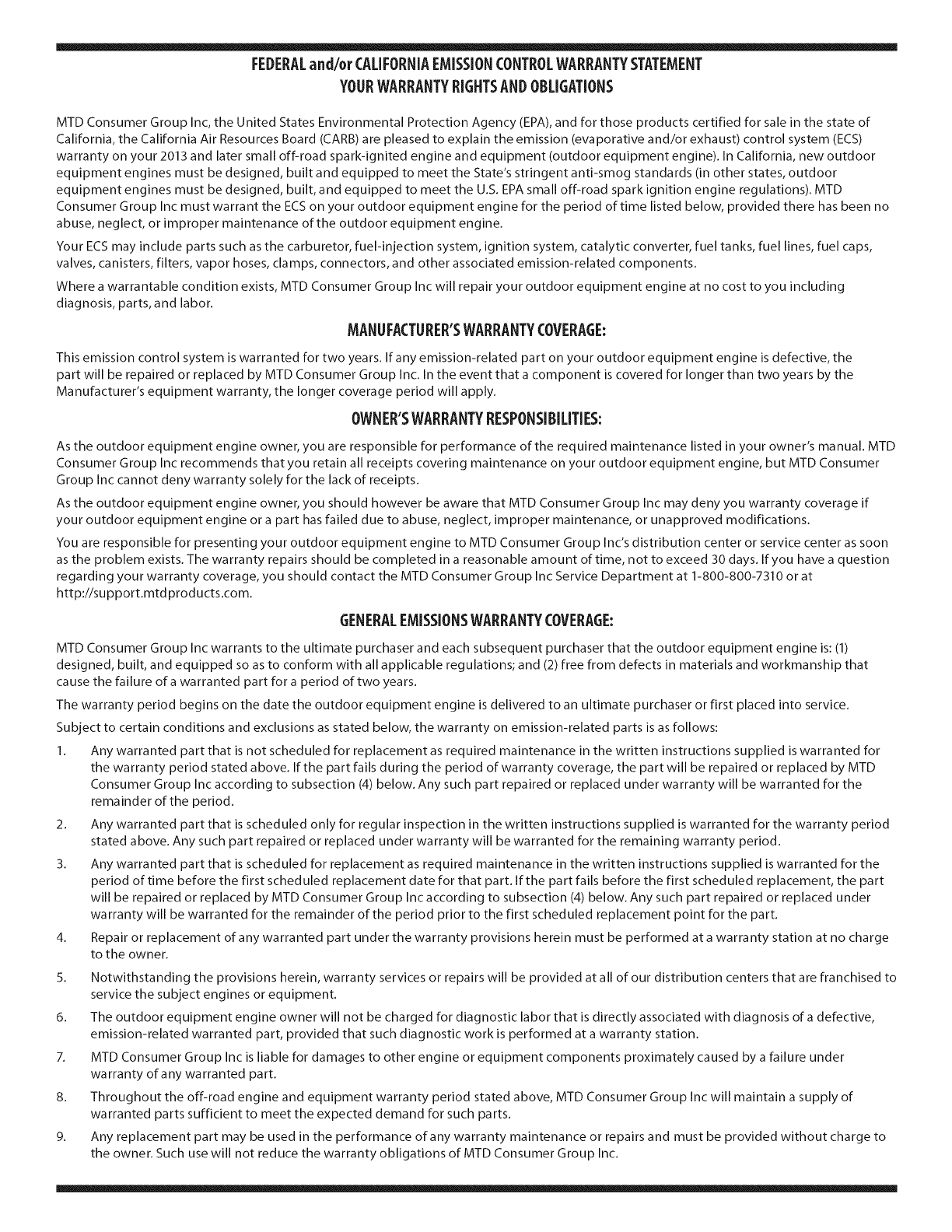
FEDERALand/or CALIFORNIAEMISSIONCONTROLWARRANTYSTATEMENT
YOURWARRANTYRIGHTSANDOBLIGATIONS
MTD Consumer Group Inc, the United States Environmental Protection Agency (EPA), and for those products certified for sale in the state of
California, the California Air Resources Board (CARB) are pleased to explain the emission (evaporative and/or exhaust) control system (ECS)
warranty on your 2013 and later small off-road spark-ignited engine and equipment (outdoor equipment engine). In California, new outdoor
equipment engines must be designed, built and equipped to meet the State's stringent anti-smog standards (in other states, outdoor
equipment engines must be designed, built, and equipped to meet the U.S. EPA small off-road spark ignition engine regulations). MTD
Consumer Group Inc must warrant the ECSon your outdoor equipment engine for the period of time listed below, provided there has been no
abuse, neglect, or improper maintenance of the outdoor equipment engine.
Your ECS may include parts such as the carburetor, fuel-injection system, ignition system, catalytic converter, fuel tanks, fuel lines, fuel caps,
valves, canisters, filters, vapor hoses, clamps, connectors, and other associated emission-related components.
Where a warrantable condition exists, MTD Consumer Group Inc will repair your outdoor equipment engine at no cost to you including
diagnosis, parts, and labor.
MANUFACTURER'SWARRANTYCOVERAGE:
This emission control system is warranted for two years. If any emission-related part on your outdoor equipment engine is defective, the
part will be repaired or replaced by MTD Consumer Group Inc. In the event that a component is covered for longer than two years by the
Manufacturer's equipment warranty, the longer coverage period will apply.
/
OWNERSWARRANTYRESPONSIBILITIES:
As the outdoor equipment engine owner, you are responsible for performance of the required maintenance listed in your owner's manual. MTD
Consumer Group Inc recommends that you retain all receipts covering maintenance on your outdoor equipment engine, but MTD Consumer
Group Inc cannot deny warranty solely for the lack of receipts.
As the outdoor equipment engine owner, you should however be aware that MTD Consumer Group Inc may deny you warranty coverage if
your outdoor equipment engine or a part has failed due to abuse, neglect, improper maintenance, or unapproved modifications.
You are responsible for presenting your outdoor equipment engine to MTD Consumer Group Inc's distribution center or service center as soon
as the problem exists. The warranty repairs should be completed in a reasonable amount of time, not to exceed 30 days. If you have a question
regarding your warranty coverage, you should contact the MTD Consumer Group Inc Service Department at 1-800-800-7310 or at
http://su pport.mtd prod ucts.com.
GENERALEMISSIONSWARRANTYCOVERAGE:
MTD Consumer Group Inc warrants to the ultimate purchaser and each subsequent purchaser that the outdoor equipment engine is: (1)
designed, built, and equipped so as to conform with all applicable regulations; and (2) free from defects in materials and workmanship that
cause the failure of a warranted part for a period of two years.
The warranty period begins on the date the outdoor equipment engine is delivered to an ultimate purchaser or first placed into service.
Subject to certain conditions and exclusions as stated below, the warranty on emission-related parts is as follows:
1. Any warranted part that is not scheduled for replacement as required maintenance in the written instructions supplied is warranted for
the warranty period stated above. If the part fails during the period of warranty coverage, the part will be repaired or replaced by MTD
Consumer Group Inc according to subsection (4) below. Any such part repaired or replaced under warranty will be warranted for the
remainder of the period.
2. Any warranted part that is scheduled only for regular inspection in the written instructions supplied is warranted for the warranty period
stated above. Any such part repaired or replaced under warranty will be warranted for the remaining warranty period.
3. Any warranted part that is scheduled for replacement as required maintenance in the written instructions supplied is warranted for the
period of time before the first scheduled replacement date for that part. If the part fails before the first scheduled replacement, the part
will be repaired or replaced by MTD Consumer Group Inc according to subsection (4) below. Any such part repaired or replaced under
warranty will be warranted for the remainder of the period prior to the first scheduled replacement point for the part.
Repair or replacement of any warranted part under the warranty provisions herein must be performed at a warranty station at no charge
to the owner.
4.
5. Notwithstanding the provisions herein, warranty services or repairs will be provided at all of our distribution centers that are franchised to
service the subject engines or equipment.
6. The outdoor equipment engine owner will not be charged for diagnostic labor that is directly associated with diagnosis of a defective,
emission-related warranted part, provided that such diagnostic work is performed at a warranty station.
7. MTD Consumer Group Inc is liable for damages to other engine or equipment components proximately caused by a failure under
warranty of any warranted part.
8. Throughout the off-road engine and equipment warranty period stated above, MTD Consumer Group Inc will maintain a supply of
warranted parts sufficient to meet the expected demand for such parts.
9. Any replacement part may be used in the performance of any warranty maintenance or repairs and must be provided without charge to
the owner. Such use will not reduce the warranty obligations of MTD Consumer Group Inc.
10. Add-onormodifiedpartsthatarenotexemptedbytheAirResourcesBoardmaynotbeused.Theuseofanynon-exemptedadd-onor
modifiedpartsbytheultimatepurchaserwillbegroundsfordisallowingawarrantyclaims.MTDConsumerGroupIncwillnotbeliableto
warrantfailuresofwarrantedpartscausedbytheuseofanon-exemptedadd-onormodifiedpart.
WARRANTEDPARTS:
The repair or replacement of any warranted part otherwise eligible for warranty coverage may be excluded from such warranty coverage if
MTD Consumer Group Inc demonstrates that the outdoor equipment engine has been abused, neglected, or improperly maintained, and that
such abuse, neglect, or improper maintenance was the direct cause of the need for repair or replacement of the part. That notwithstanding,
any adjustment of a component that has a factory installed, and properly operating, adjustment limiting device is still eligible for warranty
coverage. Further, the coverage under this warranty extends only to parts that were present on the off-road engine and equipment purchased.
The following emission warranty parts are covered (if applicable):
1. Fuel Metering System
Cold start enrichment system (soft choke)
Carburetor and internal parts (or fuel injection system)
Fuel pump
Fuel tank
2. Air Induction System
Air cleaner
Intake manifold
3. Ignition System
Spark plug(s)
Magneto ignition system
4. Exhaust System
Catalytic converter
SAI (Reed valve)
5. Miscellaneous Items Used in Above System
Vacuum, temperature, position, time sensitive valves and switches
Connectors and assemblies
6. Evaporative Control
Fuel hose
Fuel hose clamps
Tethered fuel cap
Carbon canister
Vapor lines
050790 Rev.A
Congratulationsonmakingasmartpurchase.YournewCraftsman®productisdesignedandmanufacturedforyearsof
dependableoperation.Butlikeall products,it mayrequirerepairfromtimeto time.That'swhenhavinga RepairProtection
Agreementcansaveyoumoneyandaggravation.
Here'swhat the RepairProtectionAgreement_includes:
[] Expertservice byour10,000professionalrepairspecialists
[] Unlimitedserviceand nocharge forpartsandlaboronallcoveredrepairs
[] Productreplacementupto $1500ifyourcoveredproductcan'tbefixed
[] Discountof 25%from regularpriceof serviceandrelatedinstalledpartsnot coveredbythe agreement;also,25%off
regularpriceof preventivemaintenancecheck
[] Fasthelpby phone- wecallitRapidResolution- phonesupportfromaSearsrepresentative.Thinkof usasa"talking
owner'smanual."
Onceyoupurchasethe RepairProtectionAgreement,a simplephonecallisallthat it takesforyouto scheduleservice.You
cancallanytimedayornight,orscheduleaserviceappointmentonline.
TheRepairProtectionAgreementisa risk-freepurchase.If youcancelfor anyreasonduringthe productwarrantyperiod,
wewill provideafull refund.Or,a proratedrefundanytimeafterthe productwarrantyperiodexpires.PurchaseyourRepair
ProtectionAgreementtoday!
Somelimitations and exclusionsapply. Forpricesand additional informationinthe U.S.A.call 1-800-827-6655.
_Coveragein Canadavariesonsomeitems.Forfull detailscall SearsCanadaat 1-800-361-6665.
SearsInstallationService
ForSearsprofessionalinstallationof homeappliances,garagedooropeners,waterheaters,andothermajorhomeitems,in
the U.S.A.orCanadacall1-800-4-MY-HOME®.
46

Your Home
For troubleshooting, product manuals and expert advice:
managernylife
www.managemylife.com
For repair - in your home - of all major brand appliances,
lawn and garden equipment, or heating and cooling systems,
no matter who made it, no matter who sold it!
For the replacement parts, accessories and
owner's manuals that you need to do-it-yourself.
For Sears professional installation of home appliances
and items like garage door openers and water heaters.
1-800-4-MY-HOME ®(1-800-469-4663)
Call anytime, day or night (U.S.A. and Canada)
www.sears.com www.sears.ca
Our Home
For repair of carry-in items like vacuums, lawn equipment,
and electronics, call anytime for the location of your nearest
Sears Parts & Repair Service Center
1-800-488-1222 (U.S.A.) 1-800-469-4663 (Canada)
www.sears.com www.sears.ca
To purchase a protection agreement on a product serviced by Sears:
1-800-827-6655 (U.S.A.) 1-800-361-6665 (Canada)
Para pedir servicio de reparaci6n
a domicilio, y para ordenar piezas:
1-888-SU-HOGAR ®
(1-888-784-6427)
www.sears.com
Au Canada pour service en frangais:
1-800-LE-FOYER Mc
(1-800-533-6937)
www.sears.ca
® Registered Trademark /TMTrademark of KCD IP, LLC in the United States, or Sears Brands, LLC in other countries
® Marca Registrada !TMMarca de Fabrica de KCD IP, LLC en Estados Unidos, o Sears Brands, LLC in otros paises
MCMarque de commerce !MDMarque deposee de Sears Brands, LLC
