Craftsman 315 220381 Users Manual
315220381 315220381 CRAFTSMAN 10 STATIONARY RADIAL ARM SAW - Manuals and Guides L0012257 View the owners manual for your CRAFTSMAN 10 STATIONARY RADIAL ARM SAW #315220381. Home:Tool Parts:Craftsman Parts:Craftsman 10 STATIONARY RADIAL ARM SAW Manual
CRAFTSMAN Saw Radial Manual L0012257 CRAFTSMAN Saw Radial Owner's Manual, CRAFTSMAN Saw Radial installation guides
315.220381 L0012257
315220381 c146cc5c-ea34-4e6d-82a4-674e3a6b804b Craftsman Saw 315.220381 User Guide |
2015-01-05
: Craftsman Craftsman-315-220381-Users-Manual-161097 craftsman-315-220381-users-manual-161097 craftsman pdf
Open the PDF directly: View PDF ![]() .
.
Page Count: 82
Owner's Manual
I PR OFESS IONAL I
i
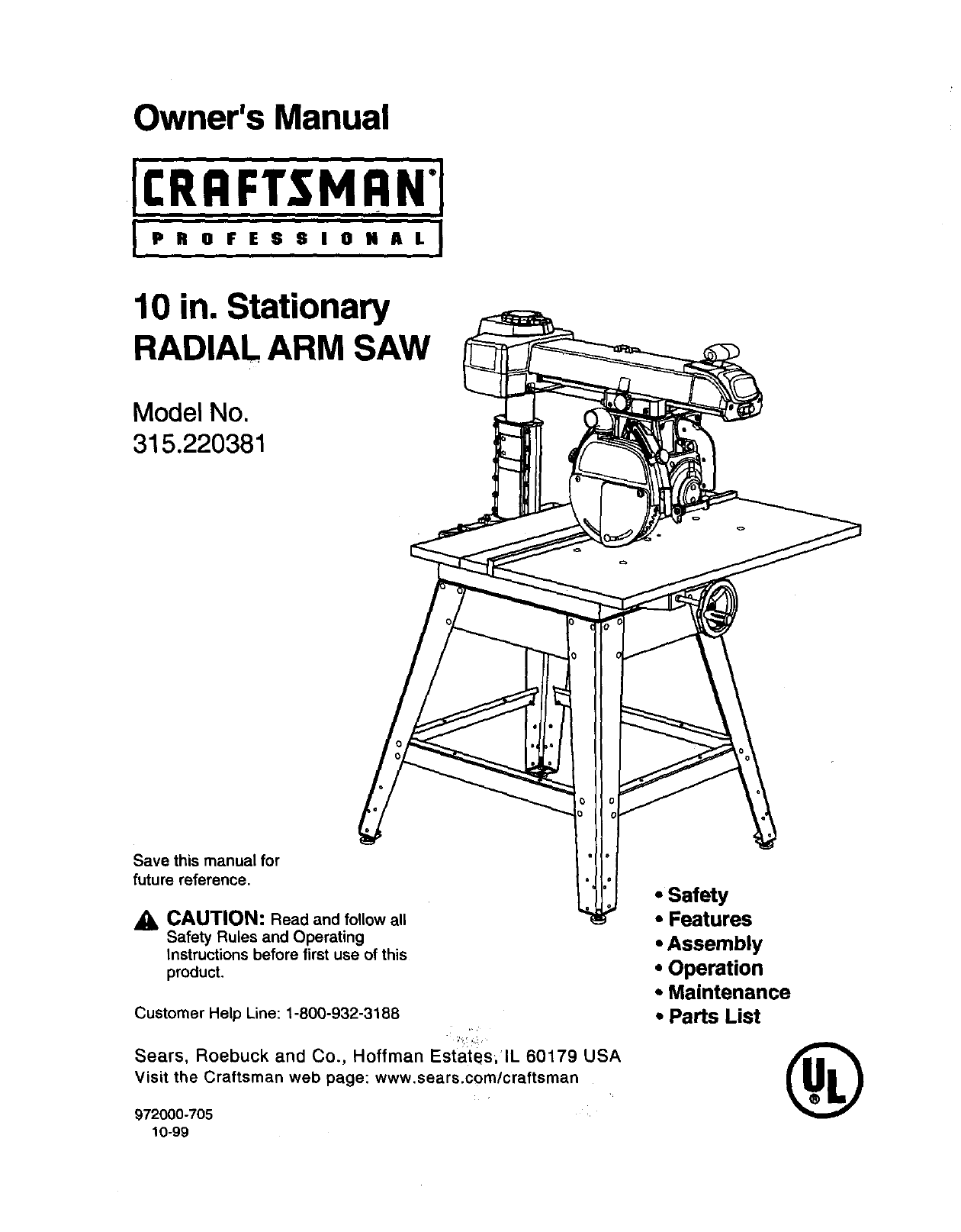
10 in. Stationary
RADIAL ARM SAW
Model No.
315.220381
Save this manual for
future reference.
CAUTION: Read and follow all
Safety Rules and Operating
Instructions before first use of this
product.
Customer Help Line: 1-800-932-3188
Sears, Roebuck and Co., Hoffman Estates,lL 60179 USA
Visit the Craftsman web page: www.sears.com/craftsman
972000-705
10-99
•Safety
•Features
•Assembly
• Operation
• Maintenance
• Parts List ®
FULL ONE YEAR WARRANTY ON CRAFTSMAN RADIAL ARM SAW
If this CRliFT,_MAN" Radial Arm Saw fails due to adefect in material or workmanshipwithinone year from the
date of purchase, Sears will repair it, free of charge.
Contact a Sears Service Center for repair.
If this product is used for commercial or rental purposes, this warranty applies onlyfor 90 days from the date of
purchase.
This warranty gives you specific legal rights,and you may also have other rightswhich vary from state to state.
Sears, Roebuck and Co., Dept. 817WA, Hoffman Estates, IL 60179
Your saw has many features for making cuttingoperations more pleasant and enjoyable. Safety, performance
and dependability have been given top priority in the design of this saw making it easy to maintain and operate.
ACAUTION: Carefully read through this entire owner'smanual before usingyour new saw. Pay close
attention to the Rules For Safe Operation, and all Safety Alert Symbols, includingDanger, Warning and
Caution. If you use your saw properlyand only for what it is intended, you will enjoy years of safe, reliable
service.
_1 Look for this symbol to point out important safety precautions. It means attentionl!! Your safety is
involved.
WARNING:
The operation of any power tool can result in foreign objects being thrown into your eyes,
which can result in severe eye damage. Before beginning power tool operation, always wear
safety goggles or safety glasses withside shieldsand a full face shieldwhen needed. We
recommend Wide Vision Safety Mask for use over eyeglasses or standard safety glasses
withside shields, available at Sears Retail Stores.
•Warranty and Introduction ............................................................................................................................... 2
•Table of Contents.......................................................................................................................................... 2-3
•Rules For Safe Operation ............................................................................................................................. 4-7
• Electrical ........................................................................................................................................................ 8-9
•ProductSpecificationsand Glossary ........................................................................................................ 10-1
•Unpackingand Accessories .......................................................................................................................... 11
•Loose Parts List ........................................................................................................................................ 12-14
•Tools Needed ................................................................................................................................................. 15
•Labels........................................................................................................................................................ 16-17
•Features .................................................................................................................................................... 18-21
•Assembly................................................................................................................................................... 22-36
Assembling Leg Stand ................................................................................................................................... 22
MountingSaw to Leg Stand ........................................................................................................................... 23
CRRFI"SHAN'RADIALSAW315.220381 2
Attaching Elevating Handwheel ..................................................................................................................... 23
Installingthe Yoke Assembly ......................................................................................................................... 24
Removing the Blade ....................................................................................................................................... 25
AttachingTable Supports .............................................................................................................................. 25
Setting the Arm Lock Knob ............................................................................................................................ 26
Setting the Yoke Clamp ................................................................................................................................. 26
Setting the Bevel Lock Lever ......................................................................................................................... 27
Tighteningthe Arm and Column .................................................................................................................... 28
Adjusting the Column Tube ...................................................................................................................... 28-29
Adjustingthe Carriage Bearings .................................................................................................................... 30
Leveling the Table Supports .......................................................................................................................... 31
Installingthe FrontTable ............................................................................................................................... 32
Leveling the Front Table ................................................................................................................................ 33
Installing Rear Table, Spacer Table, Fence, and Clamps ........................................................................ 33-34
Installing Blade and Blade Guard .................................................................................................................. 34
AligningRiving Knife to Blade ........................................................................................................................ 35
InstallingRip Scale Indicators ............................................ ,........................................................................... 36
•Adjustments .............................................................................................................................................. 36-42
Aligningthe Arm for Cross Cuts ......................................................................................... :.......................... 37
Aligningthe Blade to Table at 0" Bevel ......................................................................................................... 38
Squaring Blade to Fence ............................................................................................................................... 39
Paralleling Blade to Table .............................................................................................................................. 40
Aligningthe Rip Scale Indicators................................................................................................................... 41
InstallingControl Cut Device ......................................................................................................................... 42
•Operation .................................................................................................................................................. 43-53
Basic Operationof the Radial Arm Saw ........................................................................................................ 43
Types of Cuts ................................................................................................................................................. 43
Switch and Switch Key................................................................................................................................... 44
Causes of Kickback ....................................................................................................................................... 44
Avoiding Kickback.......................................................................................................................................... 44
Cutting Aids .................................................................................................................................................... 45
Making a Cross Cut ....................................................................................................................................... 46
Making a Miter Cut ......................................................................................................................................... 47
Making a Bevel Cut ........................................................................................................................................ 48
Making a Compound Cross Cut..................................................................................................................... 49
Rip Cut Hazards and Precautions ................................................................................................................. 50
Setting Up a Rip Cut ...................................................................................................................... _.......... 50-51
Making a Rip Cut ........................................................................................................................................... 51
Making Other Cuts ......................................................................................................................................... 52
Cutting LongWorkpieces ............................................................................................................................... 52
Non-Through Cuts ......................................................................................................................................... 53
•Maintenance .................................................................................................................................................. 54
• Troubleshooting ........................................................................................................................................ 55-59
•Exploded View and Repair Parts Ust ....................................................................................................... 60-81
•Parts Ordering /Service .................................................................................................................... back page
3i:llnlrrsNnrRADIALSAW315.220381
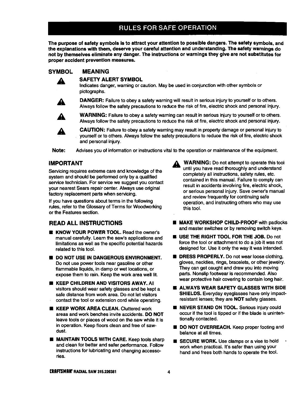
The purpose of safety symbols Is to attract your attention to possible dangers. The safety symbols, and
the explanations with them, deserve your careful attention and understanding. The safety warnings do
not by themselves eliminate any danger. The instructions or warnings they give are not substitutes for
proper accident prevention measures.
SYMBOL
A
MEANING
SAFETY ALERT SYMBOL
Indicates danger, warning orcaution. May be used in conjunctionwith other symbolsor
pictographs,
_, DANGER: Failure to obey a safety warning will result in sadous injuryto yourselfor to others.
Always followthe safety precautionsto reduce the risk of fire, electricshock and personal injury.
WARNING: Failure to obey a safety warning can result in seriousinjuryto yourselforto others.
Always followthe safety precautionsto reduce the risk of fire, electric shockand personal injury.
CAUTION: Failure to obey a safety warningmay result in propertydamage or personal injuryto
yourself or to others. Alwaysfollowthe safety precautionsto reduce the riskof fire, electric shock
and personal injury.
Note: Advises you of informationor instructionsvitalto the operationor maintenance of the equipment.
IMPORTANT
Servicing requires extreme care and knowledge of the
system and should be performed only by aqualified
service technician. For service we suggest you contact
your nearest Sears repair center. Alwaysuse original
factory replacement parts when servicing.
If you have questions about terms inthe following
rules, refer to the Glossary of Terms for Woodworking
or the Features section.
_k WARNING: Do not attempt to operate this tool
untilyou have read thoroughlyand understand
completelyall instructions,safety rules, etc.
contained in this manual. Failure to comply can
result in accidents involvingfire, electric shock,
or serious personal injury.Save owner's manual
and review frequently for continuingsafe
operation, and instructingothers who may use
this tool.
READ ALL INSTRUCTIONS
M KNOW YOUR POWER TOOL. Read the owner's
manual carefully. Learn the saw's applicationsand
limitationsas well as the specific potential hazards
related to this tool.
i DO NOT USE IN DANGEROUS ENVIRONMENT.
Do not use power tools near gasoline or other
flammable liquids,in damp or wet locations,or
expose them to rain. Keep the work area well lit.
mKEEP CHILDREN AND VISITORS AWAY. All
visitors should wear safety glasses and be kept a
safe distance from work area. Do not let visitors
contactthe tool or extension cord while operating.
MKEEP WORK AREA CLEAN. Cluttered work
areas and work benches invite accidents. DO NOT
leave tools or pieces of wood on the saw while it is
in operation. Keep floorsclean and free of saw-
dust.
nMAINTAIN TOOLS WITH CARE. Keep tools sharp
and clean for better and safer performance. Follow
instructionsfor lubricatingand changing accesso-
ries.
•MAKE WORKSHOP CHILD-PROOF with padlocks
and master switchesor by removing switch keys.
MUSE THE RIGHT TOOL FOR THE JOB. Do not
force the tool or attachment to do a job it was not
designed for. Use it only the way it was intended.
BDRESS PROPERLY. Do notwear loose clothing,
gloves, neckties, rings, bracelets, or other jewelry.
They can get caught and draw you into moving
parts. Nonslipfootwear is recommended, Also
wear protectivehair coveringto contain long hair.
i ALWAYS WEAR SAFETY GLASSES WITH SIDE
SHIELDS. Everyday eyeglasses have only impact-
resistant lenses; they are NOT safety glasses.
i NEVER STAND ON TOOL. Serious injury could
occur if the tool is tipped or ifthe blade is uninten-
tionallycontacted.
• DO NOT OVERREACH. Keep proper footingand
balance at all times.
i SECURE WORK. Use clamps or avise to hold
work when practical. It's safer than using your
hand and frees both hands to operate the tool.
[lUI_NaN' RADIALSAW316320381 4
•USE THE PROPER EXTENSION CORD. Make
sure your extension cord is in good condition,Use
only a cord heavy enough to carry the currentyour
product will draw. An undersized cord will cause a
drop in line voltage resultingin loss of power and
overheating. A wire gage size (A.W.G.) of at least
14 is recommended for an extension cord 25 feet
or less in length. If in doubt, use the next heavier
gage. The smaller the gage number, the heavier
the cord,
•AVOID ACCIDENTAL STARTING. Be sure switch
is off when pluggingin the tool.
•REMOVE WRENCHES AND ADJUSTING KEYS.
Get in the habit of checking - before turningon the
tool - that hex keys and adjustingwrenches are
removed from tool.
•CHECK DAMAGED PARTS. Before usingthe tool
again, check any damaged parts, including guards,
for proper operation and performance. Check
alignment of moving parts, bindingof moving parts,
breakage of parts, saw stability, mounting,and any
other conditionsthat may affect its operation. A
damaged part must be properly repaired or re-
placed by a qualifiedservice technician at a Sears
repair center to avoid risk of personal injury.
•USE ONLY CORRECT BLADES. Use the right
blade style for the material and the type of cut.
Use only blades marked for at least 5,000 rpmand
10 in. or smaller, with a 5/8 in. arbor hole.
•KEEP GUARDS IN PLACE and in good working
order. This includes the blade guard, the riving
knife, and the anti-kickbackpawls.
•CHECK DIRECTION OF FEED. When ripping, •
feed work into a blade or cutter against the direc-
tion of rotationof the blade or cutter.
•NEVER LEAVE TOOL RUNNING UNA'I'rENDED.
TURN THE POWER OFF. Do not leave the tool
until it comes to a complete stop.
•USE RECOMMENDED ACCESSORIES. Using
improper accessories may risk injury.Consult the
Accessories section for recommended acceSso-
ries.
•USE ONLY SEARS REPLACEMENT PARTS. All
repairs, whether electricalor mechanical, should
be made by a qualified service technician at a
Sears repair center.
DISCONNECT ALL TOOLS. When not in use,
before servicing,or when changingattachments,
blades, bits, cutters, etc., all tools should be
disconnectedfrom the power supply.
•DO NOT FORCE THE TOOL. It will do the job
better and moresafely at the rate for which it was
designed.
•BEFORE MOUNTING, DISCONNECTING OR
REMOUNTING THE MOTOR; unplugthe saw and
remove the switchkey.
_l, WARNING: When servicing,use only identical
Craftsman replacement pads. Use of any other
parts may create a hazard or damage product.
•NEVER USE THIS TOOL IN AN EXPLOSIVE
ATMOSPHERE. Normal sparking of the motor
couldignitefumes.
•MAKE SURE THE WORK AREA HAS AMPLE
LIGHTING to see the work and that no obstruc-
tions will interferewith safe operation BEFORE
performing any work using thistool.
•DO NOT USE TOOL IF SWITCH DOES NOT
TURN IT ON AND OFF. Have defective switches
replaced by aqualifiedservice technician at a
Sears repair center.
•GUARD AGAINST ELECTRICAL SHOCK by
preventing body contactwith grounded surfaces
such as pipes, radiators, ranges, refrigerator
enclosures.
•GROUND ALL TOOLS. See Electricalpage.
•WEAR A DUST MASK to keep from inhaling fine
particles. Use wood dustcollectionsystems
whenever possible.
•PROTECT YOUR HEARING. Wear hearing
protectionduring extended periods of operation.
•DO NOT OPERATE THIS TOOL WHILE UNDER
THE INFLUENCE OF DRUGS, ALCOHOL, OR
ANY MEDICATION.
STAY ALERT AND EXERCISE CONTROL. Watch
what you are doing and use common sense. Do
not operate tool when you are tired. Do not
rush.
•AVOID AWKWARD OPERATIONS AND HAND
POSITIONS where a sudden slip couldcause your
hand to move into the blade, ALWAYS make sure
you have good balance•
5 qlIIFt3NlUr RADIALSAW$15.220_t
•GUARD AGAINST KICKBACK. Kickbackcan
occur when the blade stalls, drivingthe work piece
back toward the operator. It can cause your hand
to contactthe blade, resultingin serious personal
injury. Stay out of the blade path and turn switch
off immediately if blade binds or stalls.
•DO NOT USE A PERSON AS A SUBSTITUTE
FOR A TABLE if additional support is needed. Use
a support the same height as the table.
•USE A SUPPORT FOR THE SIDES AND BACK
OF THE SAW TABLE when sawing wide or long
workpieces to minimize the risk of blade pinching
and kickback. Use a sturdy "outrigger"support to
prevent tipping if a table extension more than 24
inches long is attached to the saw.
•CUT ONLY WOOD, PLASTIC OR WOOD-LIKE
MATERIALS. Do not cut metal.
•BEFORE MAKING A CUT, be sure all adjustments
are secure.
•NEVER cut more than one piece at a time. DO
NOT STACK more than one workpiece on the saw
table at a time.
•DO NOT REMOVE THE SAW'S BLADE GUARD.
Never operate the saw withthe blade guard
removed. Make sure all guards are operating
properly before each use.
•NEVER PERFORM ANY OPERATION FREE-
HAND. Always place the workpiece to be cut on
the saw table and positionit firmly against the
fence as a backstop.
•USE THE RIP FENCE. Always use a fence or
straight edge guide when ripping.
•BE SURE THE BLADE PATH IS FREE OF
NAILS. Inspect for and remove all nails from
lumber before cutting.
•BE SURE THE BLADE CLEARS THE WORK-
PIECE. Never start the saw withthe blade touching
the stock.
•KEEP HANDS AWAY FROM CUTTING AREA.
Do not reach underneath work or in blade cutting
path with your hands and fingers for any reason.
Always turn the power off when cut is complete.
•USE A PUSHBLOCK OR PUSHSTICK in rip mode
for workpieces so small that your fingers go under
the blade guard. NEVER TOUCH BLADE or other
moving parts during use, for any reason.
•ALLOW THE MOTOR TO COME UP TO FULL
SPEED before startinga cut to avoid blade binding
or stalling.
ALWAYS PUSH THE WORKPIECE when ripping;
never pull it toward the saw.
DO NOT FEED THE MATERIAL TOO QUICKLY.
Do not force the workpiece against the blade.
•ALWAYS TURN OFF SAW before disconnecting
it,to avoid accidental startingwhen reconnecting
to the power supply. NEVER leave the saw
unattended while connected to a power source.
•BEFORE CHANGING THE SETUP, REMOVING
COVERS, GUARDS, OR BLADE; unplugthe saw
and remove the switchkey.
•KEEP TOOL DRY, CLEAN, AND FREE FROM
OIL AND GREASE. Always use a clean cloth
when cleaning. Never use brake fluids, gasoline,
petroleum-based products,or any solventsto
clean tool.
KEEP BLADES CLEAN, SHARP AND WITH
SUFFICIENT SET. Sharp blades minimize stalling
and kickback. Keep blades free of rust, grease,
and pitch.
being turnedoff.
_k WARNING: Blade coasts after " =
•USE ONLY OUTDOOR EXTENSION CORDS.
Use only extensioncords with the marking=Ac-
ceptable for use with outdoorappliances;store
indoorswhile not in use." Use extension cordswith
an electricalrating not less than the saw's rating.
Always disconnectthe extensioncord from the
outlet before disconnectingthe productfrom the
extensioncord.
INSPECT TOOL CORDS AND EXTENSION
CORDS PERIODICALLY and, if damaged, have
repaired by a qualified servicetechnician at a
Sears repaircenter. Stay constantlyaware of cord
locationand keep it well away fromthe moving
blade.
•DO NOT ABUSE CORD. Never yank the cord to
disconnectit from receptacle. Keep the cord from
heat, oil, and sharp edges.
•SAVE THESE INSTRUCTIONS. Refer to them
frequently and use to instructother users. If you
loan someone thistool, loan them these instruc-
tions also.
SAVE THESE INSTRUCTIONS
Clltl_HIIIr RADIALSAW315.220381 6
•SECURE THE SAW. Firmly belt the saw to the leg •
stand to keep the saw from tipping,walking, or
sliding.
•DO NOT SET UP WORK WITH THE BLADE
SPINNING. Keep the saw power off untilyou are
ready to use it.
•RIP ONLY WORKPIECES LONGER THAN THE
BLADE'S DIAMETER. Never rip a piece of wood
that is shorterthan the diameter of the blade.
•NEVER LOWER AN UNLOCKED REVOLVING
CUTTING TOOL. Always lockthe carriage lock
knob before lowering the blade.
•SHUT OFF THE POWER TO FREE A JAMMED
GUARD. Press the switchoff before puttingyour
hands near the blade. Wait forthe blade to stop,
then free the guard.
•LOCK THE SAW BEFORE MOVING IT. Secure
the radial arm with the arm lock knob. Secure the
carriage with the carriage lock knob.
•POSITION THE WORKPIECE WITH THE FIN-
ISHED SIDE DOWN. If the anti-kickback pawls
catch the wood to stopkickback, they could mar
the top surface or cause splintering.
•POSlI_ION THE WORKPIECE SO NO ONE MUST
STAND IN LINE WITH THE BLADE. if kickbackor
climb occurs, a helper, operator, or observer in the
sawblade path could be seriously injured.
•POSITION THE CUT SO THE WASTE PART
FALLS OFF. Never use a length stop on the free
end of the workpiece. Never apply force to the free
end or hold it while the sawblade is rotating.
_i, WARNING: In aripcut, holding the cut-off edge
behind the blade can cause the cut edges to
pinch, riskingkickback, tt couldcause the blade
to climb over the front edge of the wood and
contact your hand.
•BEFORE STARTING EACH CUT, check that no
play exists inthe carriage. Be sure the arm, yoke
and bevel locks and clamps are tight. Verify the
blade, all handles, blade washers, and blade nuts
are secure.
•BEFORE MAKING A CUT, test the upper and
lower blade guards for free movement up and
down. Positionthe nose of the guard to just clear
the workpiece.
•AVOID KICKBACK AND POSSIBLE INJURY by
preventing heeling, grabbing, and pinching.
BEFORE CUTTING, position and tighten the blade
guard and anti-kickbackpawls. Test the pawls to
make sure they would stop kickbackif it started.
Keep the pointssharp.
KEEP THE SAW BLADE PATH CLEAR. Position
the saw to allow enough room on all sides so
neitherthe operator nor a visitorstands in line with
the sawblade.
•AVOID HEELING by adjustingthe saw blade so it
exactly parallels the fence during rippingopera-
tions.
•AVOID GRABBING in rip mode by keepingthe
saw blade correctlyadjusted and by feeding the
work from the infeed side (opposite the anti-
kickbackpawls).
•AVOID PINCHING by usingarivingknife and
sharp saw blade. Keep the work positionedfirmly
against the fence.
•USE IN-RIP WHENEVER POSSIBLE by position-
ing the work so the blade is between (inside)the
columnand the motor.
'NEVER ADJUST GUARD, PAWLS, OR BLADE
WITHOUT DISCONNECTING THE POWER.
Always turn off the switchand unplugthe cord
before freeing a jammed blade, tighteninga loose
blade, or repositioningthe guard or pawls.
_k CAUTION: Do not turn the motor switch on and
off rapidly. This can loosen the sawblade.
NEVER CUT MORE THAN ONE PIECE OF
WOOD AT A TIME. The feed will be uneven and
could cause the blade to pick up one or more
pieces and cause seriousinjury.
TURN OFF SAW IF A STRANGE NOISE OR
HEAVY VIBRATION OCCURS. Immediately turn
off the saw, locate the source, and correct the
problem before using the saw further.
POSITION THE CUT SO THE BLADE WILL NOT
EXTEND BEYOND THE EDGE OF THE TABLE.
KEEP THE GUARDS IN PLACE AND THE WORK
SURFACE CLEAR DURING A CUT. Small objects
or wood slivers can ricochetfrom the blade into the
fence and back toward the operator. If the blade
loosens slivers, remove them with a stick,not your
hand.
IN A RIP CUT, DO NOT LET GO OF THE WORK-
PIECE UNTIL THE CUT IS COMPLETE. When the
workpiece is fed intothe blade, push the workplace
all the way past the blade.
7 CRIIFI"SNIIN'RADIALSAW315.220381
EXTENSION CORDS
Use only 3-wire extension cords that have 3-prong
grounding plugs and 3-pole receptacles that accept
the tool's plug. When using apower tool at a consider-
able distance from the power source, use an exten-
sion cord heavy enough to carry the current that the
tool will draw. An undersized extension cord will
cause a drop in line voltage, resulting in a loss of
power and causing the motor to overheat. Use the
chart provided below to determine the minimum wire
size required in an extension cord. Only round jack-
eted cords listed by Underwriter's Laboratories (UL)
should be used.
Length of Extension Cord Wire Size (A.W.G.)
Up to 25 feet 14
26-100 feet 12
When working with the tool outdoors, use an exten-
sion cord that is designed for outsideuse. This is
indicated by the letters WA on the cord's jacket.
Before usingan extension cord, inspect it for loose or
exposed wires and cut or worn insulation.
_k CAUTION: Keep the cord away from the cutting
area and position the cord so that it will not be
caught on lumber, tools, or other objects during
cuttingoperations.
ELECTRICAL CONNECTION
Your Sears Craftsman Radial Arm Saw is powered by
a precisionbuiltelectric motor. It should be connected
to a power supply that is 120 volta, 60 Hz, AC only
(normal household current). It should be connected
to a 240 volt power supply only if it has been reset
according to the Instructions inthis manual. The
motor has been set at the factory for 120 volts; if it is
reconnected to operate at 240 volts, the main power
cord plugand any receptacle must be replaced with
devices rated for 240 volts. This tool will not operate
on direct current (DC). A substantial voltage drop will
cause a lossof power and the motor will overheat. If
the saw does not operate when plugged into an outlet,
double check the power supply.
SPEED AND WIRING
The no-load speed of your saw is approximately 3,600
rpm. This speed is notconstant. For voltage, the
wiring in a shop is as importantas the motor's horse-
power rating. A line intended only for lightscannot
properlycarry a power tool motor. Wire that is heavy
enough for a short distance will be too lightfor a
greater distance. A line that can support one power
tool may not be able to supporttwo or three tools.
GROUNDINGINSTRUCTIONS
In the event of a malfunctionor breakdown, grounding
providesa path of least resistance for electriccurrent
to reduce the risk of electric shock. This tool is
equippedwith an electric cord having an equipment-
groundingconductorand a grounding plug. The plug
must be plugged into a matching outlet that is prepedy
installedand grounded in accordance withall local
codes and ordinances.
Do not modify the plug provided. If it will not fit the
outlet, have the proper outlet installed by aqualified
electrician. Improperconnectionof the equipment-
groundingconductorcan result in a riskof electric
shock. The conductorwith insulationhaving an outer
surfacethat is green with or withoutyellow stripes is
the equipment-groundingconductor. If repair or
replacement of the electric cord or plugis necessary,
do not connect the equipment-groundingconductorto
a live terminal.
Check with a qualified electrician or service personnel
if the grounding instructionsare notcompletely
understood,or if in doubt as to whether the tool is
propedy grounded.
Repair or replace a damaged or worn cord immedi-
ately.
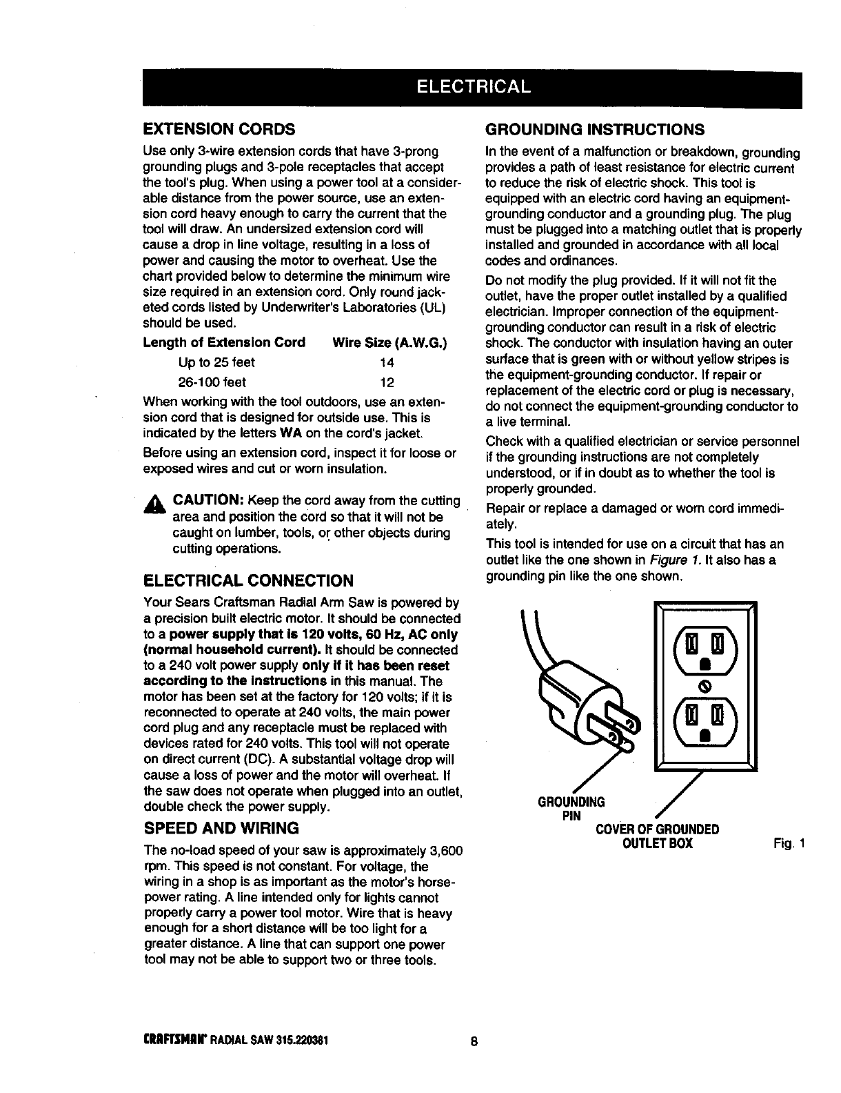
This tool is intended for use on acircuitthat has an
outlet likethe one shown in Figure 1. It also has a
grounding pin like the one shown.
GROUNDING
PIN COVEROFGROUNDED
OUTLETBOX Fig. 1
rRIIFTSNIIrRADIALSAW316.220381 8
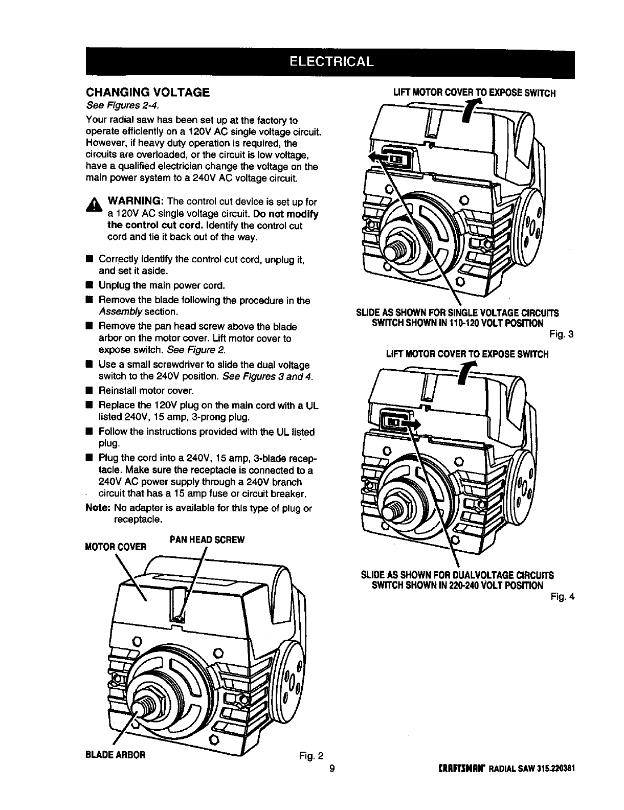
CHANGING VOLTAGE
See Figures 2-4.
Your radial saw has been set up at the factoryto
operate efficientlyon a 120V AC single voltage circuit.
However, if heavy duty operation is required, the
circuits are overloaded, or the circuitis lowvoltage,
have a qualified electrician change the voltage on the
main power system to a 240V AC voltage circuit.
,_ WARNING: The control cut device is set up for
a120V AC single voltage circuit. Do not modify
the control cut cord. Identify the controlcut
cord and tie it back out of the way.
•Correctly identifythe control cut cord, unplugit,
and set it aside.
•Unplug the main power cord.
•Remove the blade followingthe procedure in the
Assembly section.
•Remove the pan head screw above the blade
arbor on the motor cover. Liftmotor cover to
expose switch. See Figure 2.
•Use a small screwdriver to slide the dual voltage
switch to the 240V position. See Figures 3 and 4.
•Reinstall motor cover.
•Replace the 120V plugon the main cord with a UL
listed 240V, 15 amp, 3-prong plug.
•Follow the instructionsprovidedwith the UL listed
plug.
•Plug the cord into a 240V, 15 amp, 3-blade recep-
tacle. Make sure the receptacle is connectedto a
240V AC power supplythrougha 240V branch
circuitthat has a 15 amp fuse or circuitbreaker.
Note: No adapter is available for this type of plugor
receptacle.
MOTORCOVER PANHEADSCREW
LIFTMOTORCOVERTO EXPOSESWITCH
SLIDEASSHOWNFORSINGLEVOLTAGECIRCUITS
SWITCHSHOWNIN110-120VOLTPOSmON
Fig. 3
UFT MOTORCOVERTO EXPOSESWITCH
SLIDEASSHOWNFORDUALVOLTAGECIRCUITS
SWITCHSHOWNIN220-240VOLTPosmoN
Fig. 4
O
BLADEARBOR Fig. 2 9(RIIR'SHnN"RADIALSAW315.220381
BladeArbor 518in.
BladeDiameter 10in.
BladeBevelAngle 0°-90°
Radial Arm Swing Range 45" minimumleft - 90" right
Blade Height Adjust 5.35 in.
Carriage Travel 17.25 in.
Cutting Capacity - Maximum Cross Cut 15.50 in.
Cutting Capacity - Maximum Out-Rip 26 in.
Cutting Capacity -Maximum In-Rip
Depth of Cut at 90"
Depth of Cut at 45"
Table Size
Table Height
Rating
Input
No Load Speed
16 in.
3in.
2.25 in.
40 x 27.75 x1in.
36 in.
120V/240V 60 Hz -AC only
13.0/6.5 Amperes
3,600 RPM
Bevel Cut
A cut made across a workpiece with the blade at any
angle other than 90" to the table surface.
Chamfer
A cut removing awedge from ablock so the end (or
part of it) is angled rather than at 90 degrees.
Climb
A hazard in which the blade "climbs" over and out of
the workpiece, pulling the stock out of the operator's
hands or running across the workpiece.
Compound Cut
A cross cut with both a miter angle and a bevel angle.
Cross Cut
A cutting operationwith the blade parallel to the
carriage arm and the blade teeth pointingdown. It can
be across or with the grain, normally across the grain
or width of the workpiece.
Dado Cut
A non-throughcut that leaves a square notch or
trough; requires a special blade.
Featherboard
A device to help guide workpieces during ripcuts•
Fence
Apiece of wood used as a edge guide for the
workpiece. Located perpendicular to the carriage arm.
Can be placed at different distances from the rear
table edge in combination with the other table pieces
and is secured with table clamps•
Freehand
Dangerous practice of making a cut withoutusinga
fence.
Gum
A sticky,sap-based residue from wood products.
Heel
Alignment of the blade to the fence.
Infeed
The side of the blade where the blade teeth pointup,
opposite the anti-kickback pawls.
In-Rip
Atype of rip cut in which the blade is between the
columnand the motor.
Kerr
The space left by the removal of material in a cut or
the slotproduced by the blade in a non-throughcut.
Kickback
A hazard that can occur when blade binds or stalls,
throwing workpiece back toward operator.
Leading End
The end of the workpiece pushed into the cuttingtool
first.
Miter Cut
Avertical cut made at any angle other than 0" across
the workpiece.
Molding
A shapingcut that gives avaried shape to the
workpiece and requires a special blade.
Out-Rip
Atype of rip cut in which the motor is between the
blade and the column• (The blade is "outside" the
motor).
Puahatick
A device used to feed the workpiece throughthe saw
blade duringcutting operations. It helps keep the
operator's hands well away from the blade.
Rabbet
Atype of cut that gives a notch inthe edge of a
workpiece.
Resaw
Acuttingoperation to reduce the thickness of the
workpiece to make thinner pieces,
[IIRR3MIIIr RADIALSAW31S_220381 10
Resin
Asticky, sap-based substance.
Rip Cut
In a radial saw, a cut made with the blade parallel to
the fence and perpendicular to the arm. Can be
across or with the grain. The teeth point up at the
point of contact with the wood.
Sawblade Path
The area directly in line with the blade -- over, under,
behind, or in front of it. Also, the workpiece area which
will be or has been cut by the blade.
Set
The distance that the tip of the saw blade tooth is off
set from the face of the blade.
Throw-Back
Saw throwingback a workpiece similarto kickback.
Through Sawing
Any cuttingoperation where the blade extends
completelythroughthe workpiece.
Trailing End
The workpiece end last cut by the blade in a rip cut.
Workpiece
The item on which the cuttingoperation is being done.
The surfaces of a workpiece are commonly referredto
as faces, ends, and edges.
Worktable
The surface on which the workpiece rests while
performinga cuttingoperation.
_i, WARNING: To prevent accidental startingthat
could cause possible serious personal injury,
assemble all parts to your saw before connecting
it to power supply. The saw should never be
connected to the power supply when you are
assembling parts, making adjustments, installing
or removing blades, or when not in use.
_lb WARNING: If any parts are missing, do not
operate this tool untilthe missing parts are
replaced. Failure to do so could result in possible
serious personal injury.
•Carefully remove all partsfrom the carton and
placethe saw on a level work surface. Separate
and check against the listof loose parts.
•Do not discardthe packingmaterials untilyou have
carefully inspectedthe saw, identifiedall parts, and
satisfactorilyoperated your new saw.
Note: If any parts are damaged or missing, do not
attempt to plug in the power cord and turn the
switchon untilthe damaged or missingparts
are obtained and are installed correctly.
The following recommended accessories are currently availableat Sears Retail Stores.
•Steel and carbide tipped circular saw blades •Adjustabletaper jig
•Hold down clamps •Sawdust collector shroud
•Saw baskets
_lb WARNING: The use of attachments or accessories not listed might be hazardous.
1 1 [RAFTSNAN' RADIALSAW315,220381
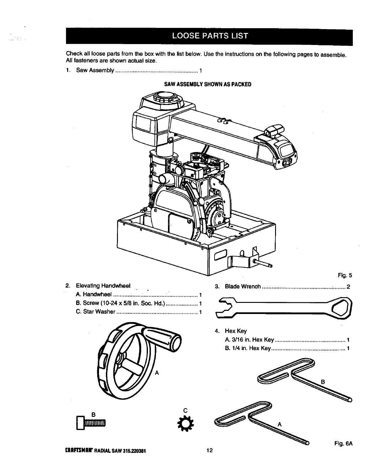
Check all loose parts from the box with the list below. Use the instructionson the followingpages to assemble.
All fasteners are shown actual size.
1. Saw Assembly .................................................... 1
SAWASSEMBLYSHOWNASPACKED
2. Elevating Handwheel .
A. Handwheel .......... :.......... _..........:.................... 1
B. Screw (10-24 x 5/8 in. Soc. Hd.) .................... 1
C. Star Washer ................................................... 1
C
[lUlFTSMIIM' RADIALSAW315.220381
Fig. 5
3. Blade Wrench ..................................................... 2
12
4. Hex Key
A. 3/16 in. Hex Key ............................................. 1
B. 1/4 in. Hex Key............................................... 1
Fig. 6A
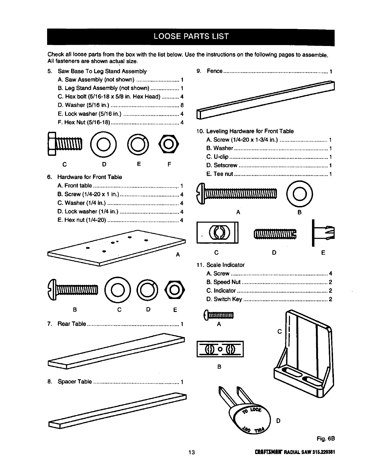
Checkall loose parts from the box with the list below. Use the instructionson the followingpages to assemble.
All fasteners are shown actual size.
5. Saw Base To Leg Stand Assembly
A. Saw Assembly (notshown) ........................... 1
B. Leg Stand Assembly (not shown) .................. 1
C. Hex bolt (5/16-18 x 518in. Hex Head) ........... 4
D. Washer (5/16 in.) ........................................... 8
E. Lock washer (5/16 in.) ................................... 4
F. Hex Nut (6/16-18) ........................................... 4
C D E F
9. Fence.................................................................. 1
6. Hardware for Front Table
A. Fronttable .................................................... ,. 1
B, Screw (1/4-20 x 1 in.) ..................................... 4
C. Washer (1/4 in.) ............................................. 4
D. Lock washer (1/4 in.) ..................................... 4
E. Hex nut (1/4-20) ............................................. 4
11. Scale Indicator
B C D E
7. Rear Table ........................................................... 1
8. Spacer Table ...................................................... 1
10. Leveling Hardware for FrontTable
A. Screw (1/4-20 x 1-3/4 in.) .............................. 1
B. Washer ........................................................... 1
C, U-clip.............................................................. 1
D. Setscrew ........................................................ t
E. Tee nut........................................................... 1
AB
D E
A. Screw ............................................................. 4
B. Speed Nut ...................................................... 2
C. Indicator ......................................................... 2
D. Switch Key ..................................................... 2
IIoII
C
Fig. 6B
13 CHR2NH"RADIALSAW316,220381
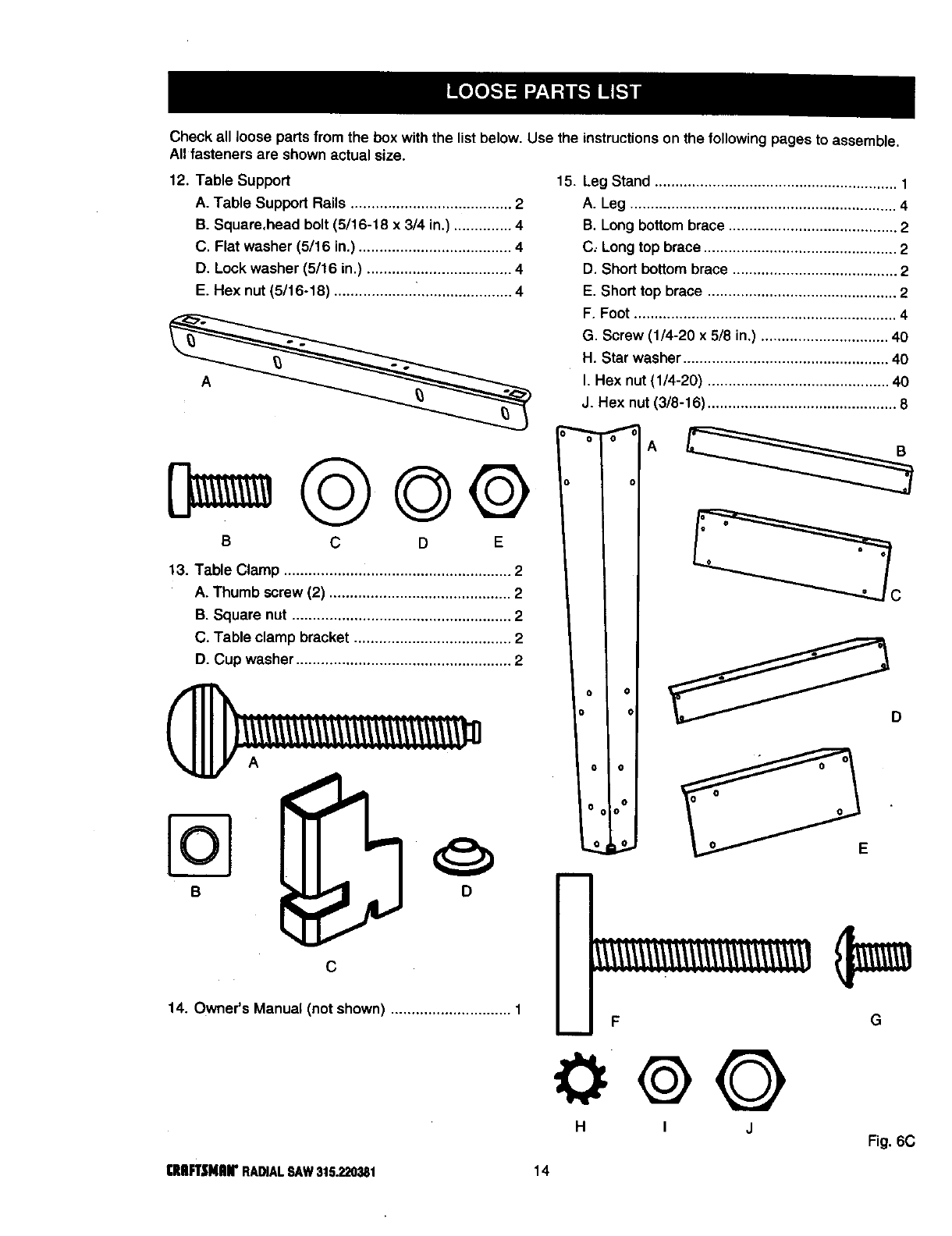
Check all loose partsfrom the box withthe list below. Use the instructions on the following pages to assemble.
All fasteners are shown actual size.
12. Table Support
A. Table Support Rails ....................................... 2
B. Square,head bolt (5/16-18 x 3/4 in.) .............. 4
C. Flat washer (5/16 in.) ..................................... 4
D. Lock washer (5/16 in.) ................................... 4
E. Hex nut (5/16-18) .................... ....................... 4
A
15. Leg Stand ........................................................... 1
A. Leg ................................................................. 4
B. Long bottom brace ......................................... 2
C, Long top brace ............................................... 2
D. Short bottom brace ........................................ 2
E. Short top brace .............................................. 2
F. Foot ................................................................ 4
G. Screw (1/4-20 x 5/8 in.) ............................... 40
H. Star washer .................................................. 40
I. Hex nut (1/4-20) ............................................ 40
J. Hex nut (3/8-16) .............................................. 8
14. Owner's Manual (not shown) ............................. 1 F
m
G
000
H I J Fig. 6C
CRIIFT,_NAIrRADIALSAW315.220381 14
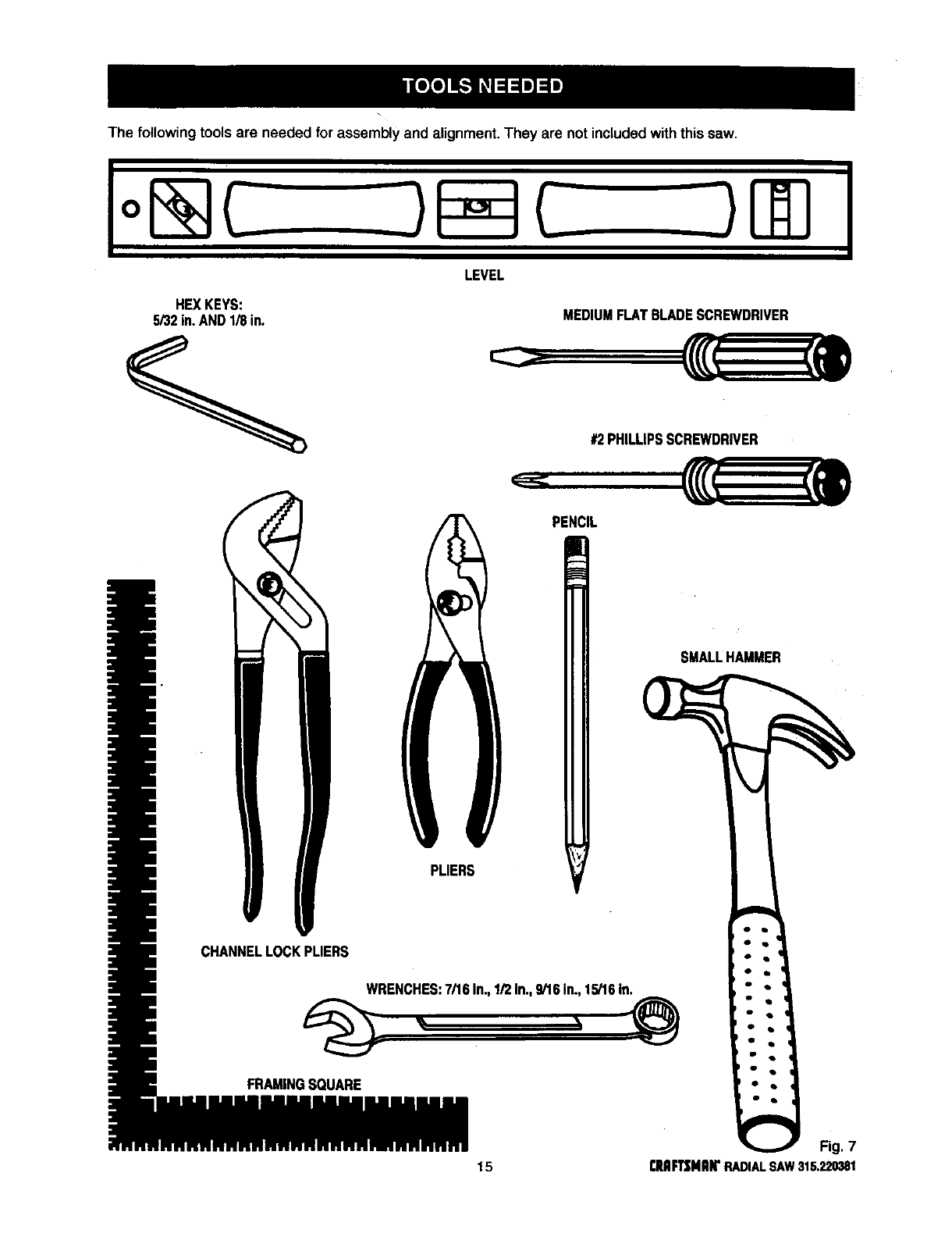
The following tools are needed for assemblyand alignment. They are not includedwith this saw.
io@C
HEXKEYS:
5/32in.ANDI/8 in.
LEVEL
MEDIUMFLATBLADESCREWDRIVER
#2PHILLIPSSCREWDRIVER
PENCIL
SMALLHAMMER
PLIERS
WRENC S 7/161n,1/21n,9/161n_15/161n
FRAMINGSQUARE
Fig. 7
t5rEAFTSMRIrRADIALSAW315.220381
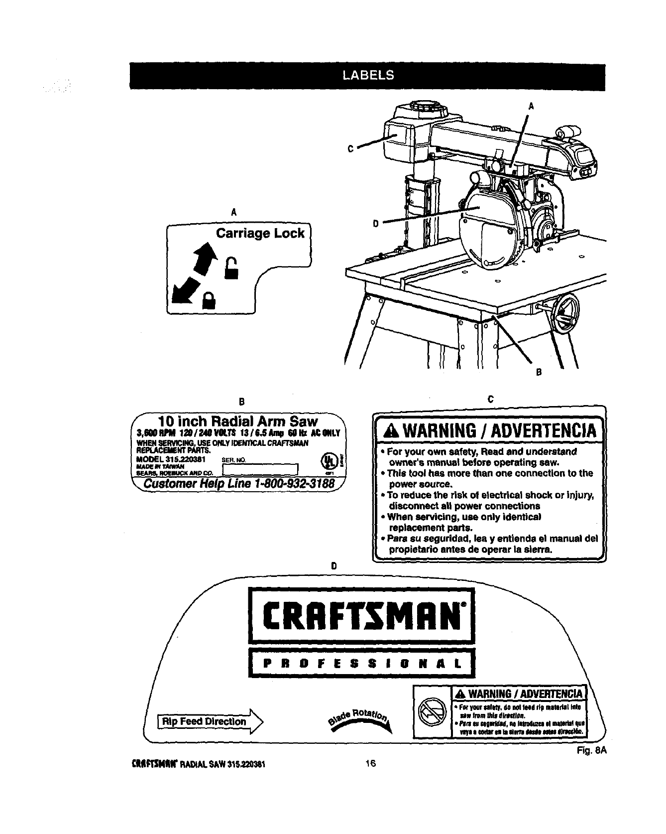
A
A
(I 10 inch Radii Arm Saw
I3,_RPM 120/?._ImVOLT_1316.SAJnp60Hz ACONLYI
I WHEN_RVlCING,USEOl'€.yI_NTICALC_ |
I RE_.A_NTPARTS. _r
I MOOEL 315.22_181 SER,NO /_1_ i I
D
c
i
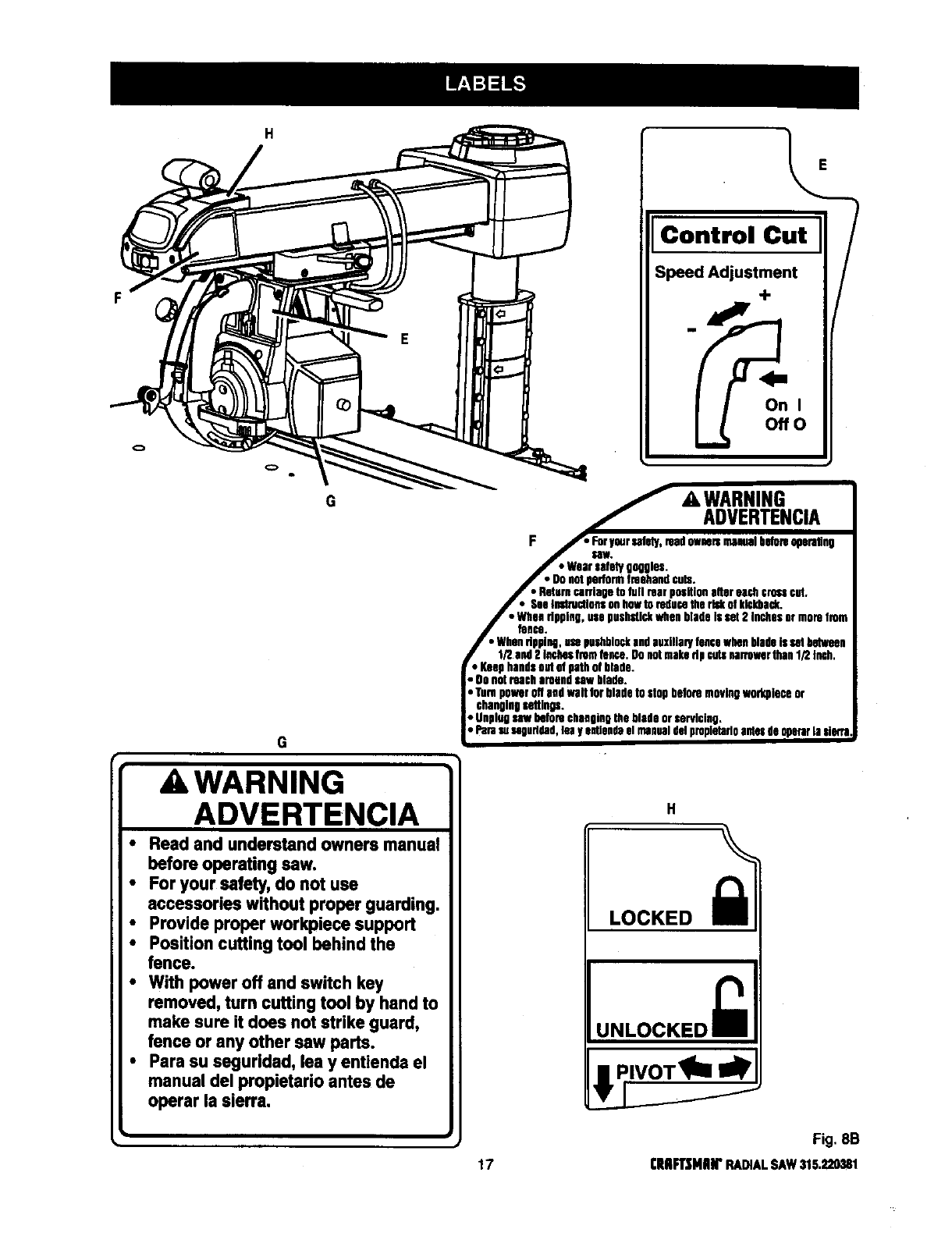
A WARNING/ADVERTENCIA
ill
• For your own safety, Read and understand
owner's manual before operating saw.
*This tool has more than one connection to the
power soorce.
. To reduce the risk of electrical shock or injury,
disconnect al| power connections
•When servicing, use only identical
replacement parts.
• Par,, su seguddad, lea y entlenda el manual del
propieterio antes de oparer la sierra,
lilll I_
,I
Fig. 8A
£HfTg411r RAI_L SAW$IS_20_ 16
G
G
_WARNING
ADVERTENCIA
• Read and understand owners manual
before operating saw.
•For your safety, do not use
accessories without proper guarding.
•Provide proper workpiece support
•Position cutting tool behind the
fence.
•With power off and switch key
removed, turn cutting tool by hand to
make sure it does not strike guard,
fence or any other saw parts.
• Pars su saguridad, lea y entienda el
manual del propietario antes de
operar la sierra.
On I
OffO
./" A WARNING
;_,,_,.. ADVERTENCIA
F_ _[yo, ra.duty,readownersremrelbeloreqereUng
jv
jr • Wearsofely goggles.
_r • DOnotperformfreehandcuts.
jr •Returncarriageto full roar positionaftereach crosscut.
jr • See thutnmtisnsonhowto reducetheriskofkickback,
jr • Whenripping,usepushsUchwhenbladeis set 2 Inchesormorefrom
/then.
j_ • Whenripping,usepuchbthckandauxiliaryfencewhenbladeis osl between
1/2 and2 Inchesfromfelwe. Denutreakedp cutsosrmwar thsa1/2tnch.
• KeephandsOutof pathof blade.
• no notreacharoundsawblade.
• TurnpowerOftandwaif forbladeto stepbeforereevingwarkplose or
changing|eRinos.
•Unplugsawbeforechangingthe bladeor servicing,
•Parssuseguridad,lea y entlendeel manualdel preplutarloantesde opersrla sierra
H
LOCKED
UNLOCKED
,Fig, 8B
17 rltllFI3NIIlr RADIALSAW315.220381
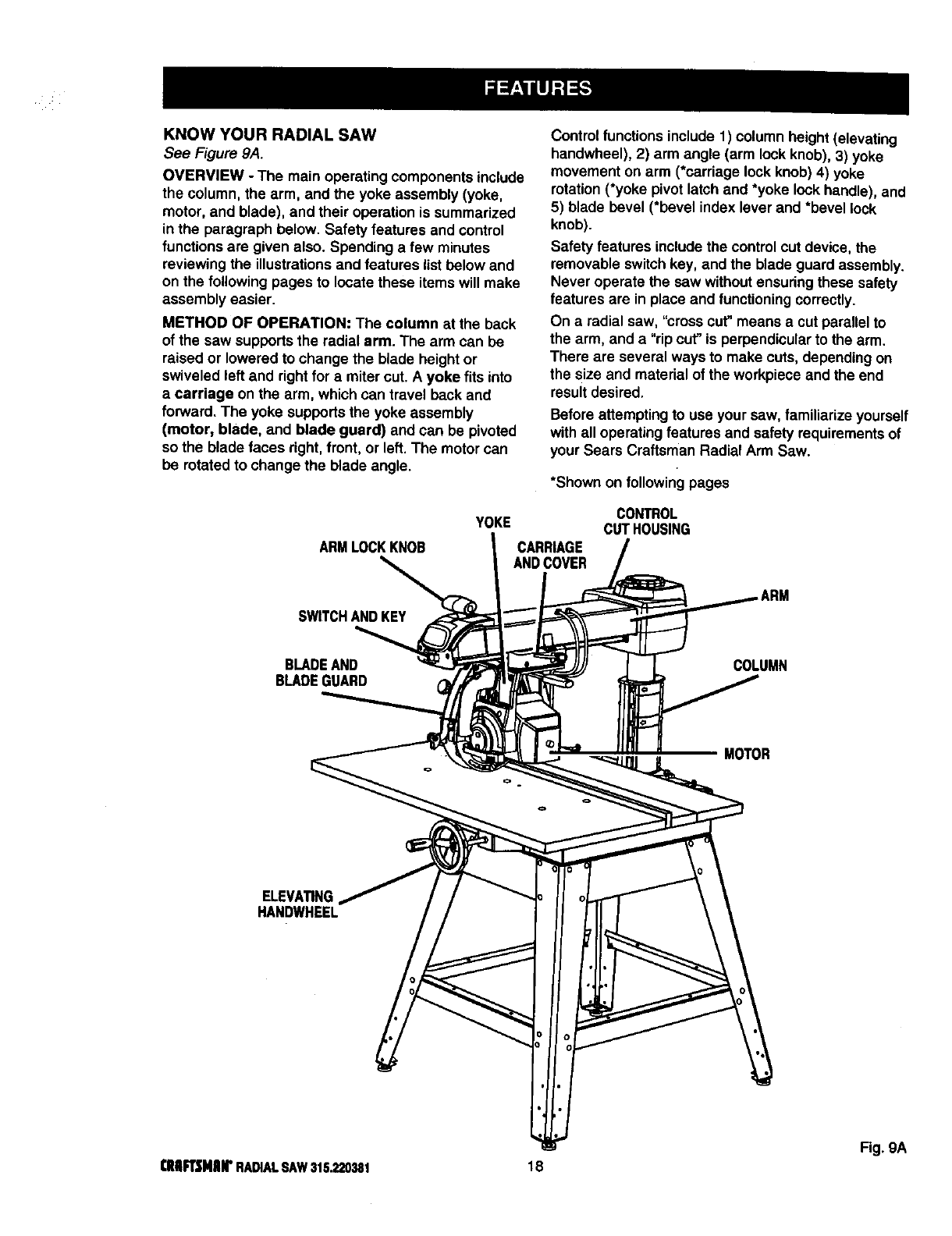
KNOWYOURRADIALSAW
See Figure 9A.
OVERVIEW -The main operatingcomponents include
the column, the arm, and the yoke assembly (yoke,
motor, and blade), and their operationis summarized
in the paragraph below. Safety features and control
functionsare given also. Spending a few minutes
reviewing the illustrationsand features listbelow and
on the following pages to locate these items will make
assembly easier.
METHOD OF OPERATION: The column at the back
of the saw supports the radial arm. The arm can be
raised or lowered to change the blade height or
swiveled left and rightfor a mitercut. A yoke fits into
a carriage on the arm, which can travel back and
forward. The yoke supportsthe yoke assembly
(motor, blade, and blade guard) and can be pivoted
so the blade faces right, front, or left. The motor can
be rotated to change the blade angle.
Control functions include 1) column height(elevating
handwheel), 2) arm angle (arm lock knob), 3) yoke
movement on arm (*carriage lockknob) 4) yoke
rotation(*yoke pivot latch and *yoke lock handle), and
5) blade bevel (*bevel index lever and *bevel lock
knob).
Safety features includethe control cut device, the
removable switchkey, and the blade guard assembly.
Never operate the saw withoutensuringthese safety
features are in place and functioning correctly.
On aradial saw, "cross cut"means a cut parallel to
the arm, and a "rip cut" is perpendicularto the arm.
There are several ways to make cuts, depending on
the size and material of the workpieceand the end
resultdesired.
Before attemptingto use your saw, familiarize yourself
with all operatingfeatures and safety requirementsof
your Sears Craftsman Radial Arm Saw.
*Shown on following pages
ARMLOCKKNOB
YOKE
CARRIAGE
ANDCOVER
CONTROL
CUTHOUSING
SWITCHANDKEY
BLADEAND
BLADEGUARD COLUMN
MOTOR
ELEVA_NG
HANDWHEEL
Fig. gA
cRnFt3MIIrRADIALSAW315.220381 18
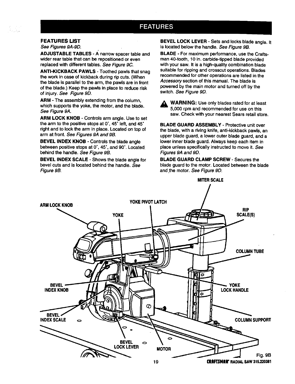
FEATURESLIST
See Figures 9A-9D.
ADJUSTABLE TABLES - A_narrow spacer table and
wider rear table that can be repositionedoreven
replaced with different tables. See Figure 9C.
ANTI-KICKBACK PAWLS -Toothed pawls that snag
the work in case of kickbackduring rip cuts. (When
the blade is parallel to the arm, the pawls are in front
of the blade.) Keep the pawls in place to reduce risk
of injury. See Figure 9D.
ARM -The assembly extending from the column,
which supports the yoke, the motor,and the blade.
See Figure 9A.
ARM LOCK KNOB -Controls arm angle. Use to set
the arm to the positivestops at 0°, 45" left, and 45"
rightand to lock the arm in place. Located on top of
arm at front. See Figures 9A and 9B.
BEVEL INDEX KNOB -Controls the blade angle
between positivestopsat 0°, 45", and 90°. Located
behind the handle. See Figure 9B.
BEVEL INDEX SCALE - Shows the blade angle for
bevel cuts and is located behind the handle. See
Figure 9B.
BEVEL LOCK LEVER -Sets and locksblade angle. It
is located below the handle. See Figure 9B.
BLADE -For maximum performance, use the Crafts-
man 40-tooth, 10 in. carbide-tipped blade provided
with your saw. It is a high-qualitycombination blade
suitablefor rippingand crosscut operations. Blades
recommended for other operationsare listed in the
Accessory section of this manual. The blade is
powered by the main motor and turned off by the
switch. See Figure 9D.
,_ WARNING: Use only blades rated for at least
5,000 rpm and recommended for use onthis
saw. Check with your nearest Sears retail store.
BLADE GUARD ASSEMBLY -Protective unit over
the blade, with a riving knife, anti-kickback pawls, an
upper blade guard, alower outer blade guard, and a
lower inner blade guard. Always keep each item in
place unless specificallyinstructedto move it. See
Figures 9A and 9D.
BLADE GUARD CLAMP SCREW -Secures the
blade guard to the motor. Located between the blade
andthe motor. See Figure 9D.
MITERSCALE
ARMLOCKKNOB
YOKE
YOKEPIVOTLATCH
RIP
SCALE(S)
COLUMNTUBE
BEVEL
INDEXKNOB YOKE
LOCKHANDLE
INDEXSCALE
ER MOTOR
19
COLUMNSUPPORT
Fig. gB
(IIRFTSMRN"RADIALSAW315.220381
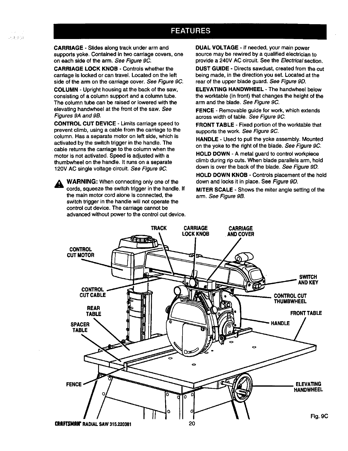
CARRIAGE- Slidesalongtrackunderarmand
supportsyoke.Containedintwocarriagecovers,one
oneachsideofthearm.See Figure 9C.
CARRIAGE LOCK KNOB - Controlswhether the
cardage is locked or can travel. Located on the left
side of the arm on the carriage cover. See Figure 9C.
COLUMN - Upright housingat the beck of the saw,
consistingof a column support and a columntube.
The column tube can be raised or lowered withthe
elevating handwheel at the front of the saw. See
Figures 9A and 9B.
CONTROL CUT DEVICE - Limitscarriage speed to
prevent climb, usingacable from the carriage to the
column. Has a separate motor on left side, which is
activated by the switchtrigger inthe handle. The
cable returnsthe carriage to the columnwhen the
motor is not activated. Speed is adjusted with a
thumbwheel on the handle. It runs on a separate
120V AC single voltage circuit. See Figure 9C.
_1, WARNING: When connectingonly one of the
cords, squeeze the switchtrigger inthe handle. If
the main motor cord alone is connected, the
switchtrigger inthe handle will notoperate the
controlout device. The carriage cannot be
advanced without power to the control cut device.
DUAL VOLTAGE - If needed, your main power
source may be rewired by a qualified electricianto
providea 240V AC circuit. See the Electricalsection.
DUST GUIDE - Directs sawdust, created from the cut
being made, in the directionyou set. Located at the
rear of the upper blade guard. See Figure 9D.
ELEVATING HANDWI-IEEL - The handwbeel below
the worktable (in front) that changes the height of the
arm and the blade. See Figure 9C.
FENCE - Removable guide for work, which extends
acrosswidth of table. See Figure 9C.
FRONT TABLE - Fixed portionof the worktable that
supportsthe work. See Figure 9C.
HANDLE - Used to pullthe yoke assembly. Mounted
on the yoke to the rightof the blade. See Figure 9C.
HOLD DOWN - A metal guard to control workpiece
climb during rip cuts.When blade parallels arm, hold
down is over the back of the blade. See Figure 9D.
HOLD DOWN KNOB - Controls placement of the hold
down and locks it in place. See Figure 9D.
MITER SCALE - Shows the miter angle setting of the
arm. See Figure 9B.
TRACK CARR_GE CARRIAGE
LOCKKNOB ANDCOVER
CONTROL
CUTMOTOR
CUTCABLE
REAR
TABLE
SPACER
TABLE
SWITCH
ANDKEY
CONTROLCUT
THUMBWHEEL
FRONTTABLE
ELEVATING
HANDWHEEL
Fig. 9C
[RFT|NnlrRADIALSAW315.220381 20
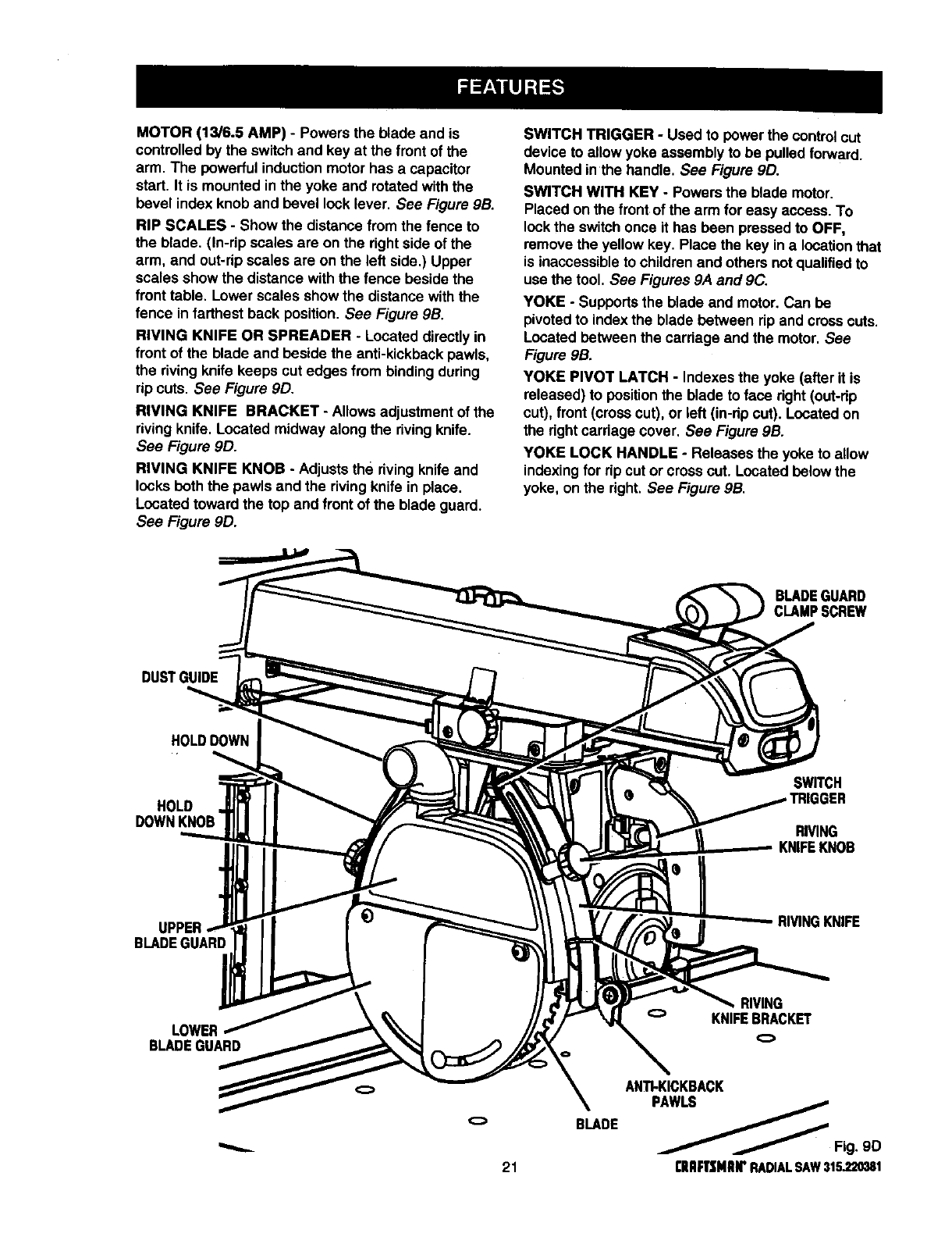
MOTOR(13/6.5AMP)- Powersthebladeand is
controlled by the switch and key at the front of the
arm. The powerful induction motor has a capacitor
start. It is mounted in the yoke and rotated with the
bevel index knob and bevel lock lever. See Figure 9B.
RIP SCALES - Show the distance fromthe fence to
the blade. (in-rip scales are on the right side of the
arm, and out-rip scales are on the left side,) Upper
scales show the distance with the fence beside the
front table. Lower scales showthe distance with the
fence infarthest back position. See Figure 9B.
RIVING KNIFE OR SPREADER - Located directlyin
front of the blade and beside the anti-kickbackpawls,
the riving knife keeps cut edges from binding during
rip cuts. See Figure 9D.
RIVING KNIFE BRACKET - Allows adjustment of the
riving knife. Located midway along the rivingknife.
See Figure 90.
RIVING KNIFE KNOB - Adjusts the rivingknife and
locks both the pawls and the rivingknife in place.
Located toward the top and front of the blade guard.
See Figure 9D.
SWITCH TRIGGER -Used to power the controlcut
device to allow yoke assembly to be pulled forward.
Mounted inthe handle. See Figure 9D.
SWITCH WITH KEY -Powers the blade motor.
Placed on the front of the arm for easy access. To
lockthe switchonce it has been pressed to OFF,
remove the yellow key. Place the key in a locationthat
is inaccessibleto childrenand others not qualifiedto
use the tool. See Figures 9A and 9C.
YOKE -Supportsthe blade and motor. Can be
pivoted to indexthe blade between rip and cross cuts.
Located between the carriage and the motor. See
Figure 9B.
YOKE PIVOT LATCH - Indexes the yoke (after it is
released) to position the blade to face right (out-rip
cut), front (cross cut), or left (in-np cut). Located on
the rightcarriage cover. See Figure 9B.
YOKE LOCK HANDLE -Releases the yoke to allow
indexingfor rip cut or cross cut. Located below the
yoke, on the right. See Figure 9B.
BLADEGUARD
CLAMPSCREW
DUSTGUIDE
HOLDDOWN
HOLD
DOWNKNOB
SWITCH
RIVING
KNIFEKNOB
BLADEGUARD
RIVINGKNIFE
BLADEGUARD
o
21
BLADE
RIVING
KNIFEBRACKET
o
ANTI-KICKBACK
PAWLS
_Fig. 9D
[IIRFI]KNIIWRADIALSAW315,220381
Assembly is best done in the area where the saw will
be used. When you remove the saw and hardware
from the packing materials, carefully check the items
withthe Loose Parts list. If you are unsure about the
descriptionof any part, refer to their illustrations.For
your convenience, all fasteners have been drawn
actual size. If any parts are missing, delay assembling
untilyou have obtained the missingpart(s).
Your radial arm saw is capable of a wide varietyof
operations, and thus requires a number of initialsetup
adjustments. However, once the saw is set up, you
can check your saw in about ten minutes and correct
any misalignmentwith the procedures in the Adjust-
ment section.
_1= CAUTION: Perform all the procedures in both
the Assembly and Adjustments sectionsbefore
using the saw. Run a check on your saw
frequently, referringto the Adjustmentssection.
Failure to perform the adjustments in the initial
set up or on a frequent basis can result in boor
performance or machine damage.
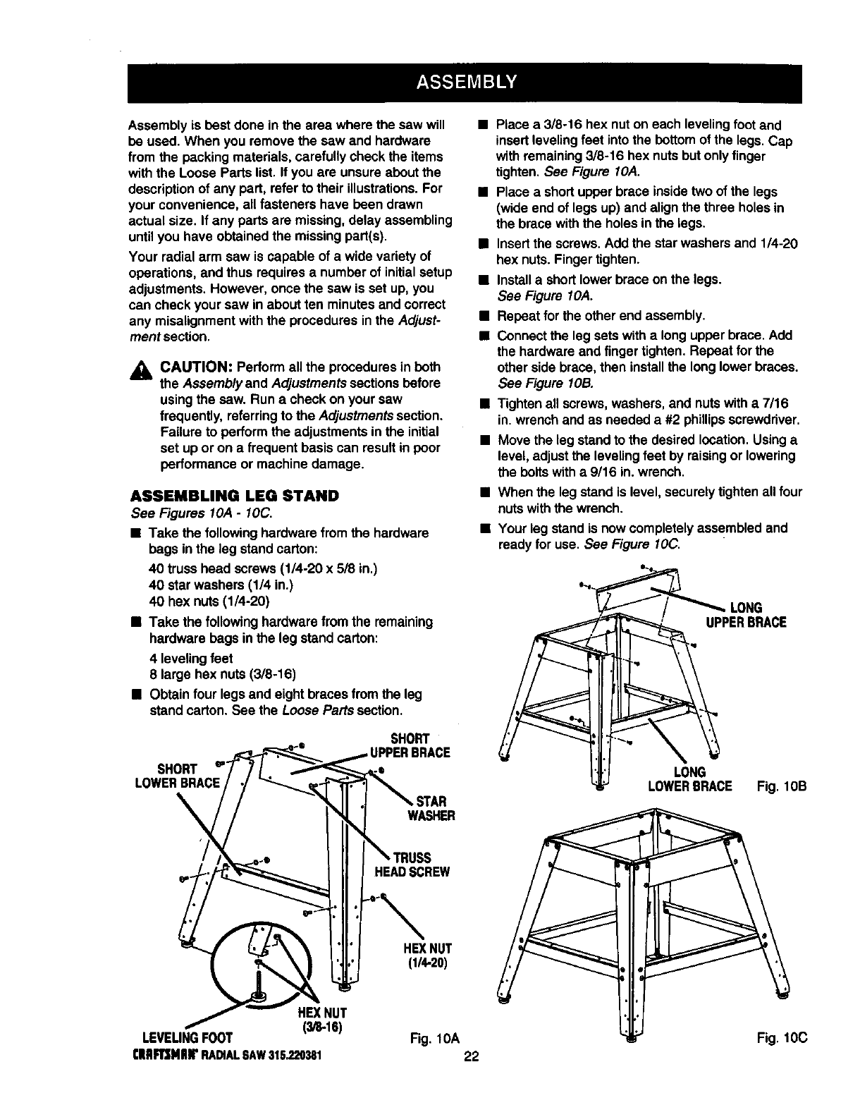
ASSEMBLING LEG STAND
See Figures 10,4-10C.
•Take the followinghardware from the hardware
bags inthe leg stand carton:
40 truss head screws (1/4-20 x 5/8 in.)
40 star washers (1/4 in.)
40 hex nuts (1/4-20)
•Take the followinghardware from the remaining
hardware bags inthe leg stand carton:
4 leveling feet
8 large hex nuts (3/8-16)
•Obtain four legs and eight braces from the leg
stand carton. See the Loose Pans section.
•Place a 3/8-16 hex nut on each leveling foot and
insert leveling feet intothe bottom of the legs. Cap
with remaining3/8-16 hex nutsbut only finger
tighten. See Figure I OA.
•Place a short upper brace insidetwo of the legs
(wide end of legs up) and alignthe three holes in
the brace with the holes inthe legs.
•Insert the screws.Add the star washers and 1/4-20
hex nuts. Finger tighten.
•Installa short lower brace on the legs.
See Figure I OA.
•Repeat for the other end assembly.
•Connect the leg sets with a longupper brace. Add
the hardware and finger tighten. Repeat forthe
other side brace, then installthe long lower braces.
See Figure lOB.
•Tighten all screws,washers, and nutswith a 7/16
in. wrench and as needed a #2 phillipsscrewdriver.
•Move the leg standto the desired location.Usinga
level, adjustthe leveling feet by raising or lowering
the boltswith a9/16 in. wrench.
• When the leg stand is level, securely tighten all four
nutswith the wrench.
•Your leg stand is now completelyassembled and
ready for use. See Figure 10C.
LONG
UPPERBRACE
SHORT
SHORT
LOWERBRACE
WASHER
HEADSCREW
HEXNUT
(1/4-20)
HEXNUT
(3/8.16)
LEVEUNGFOOT Fig. lOA
[|BmNI_RA_ALSAW315.220_I 22
LONG
LOWERBRACE Fig. lOB
Fig. 10C
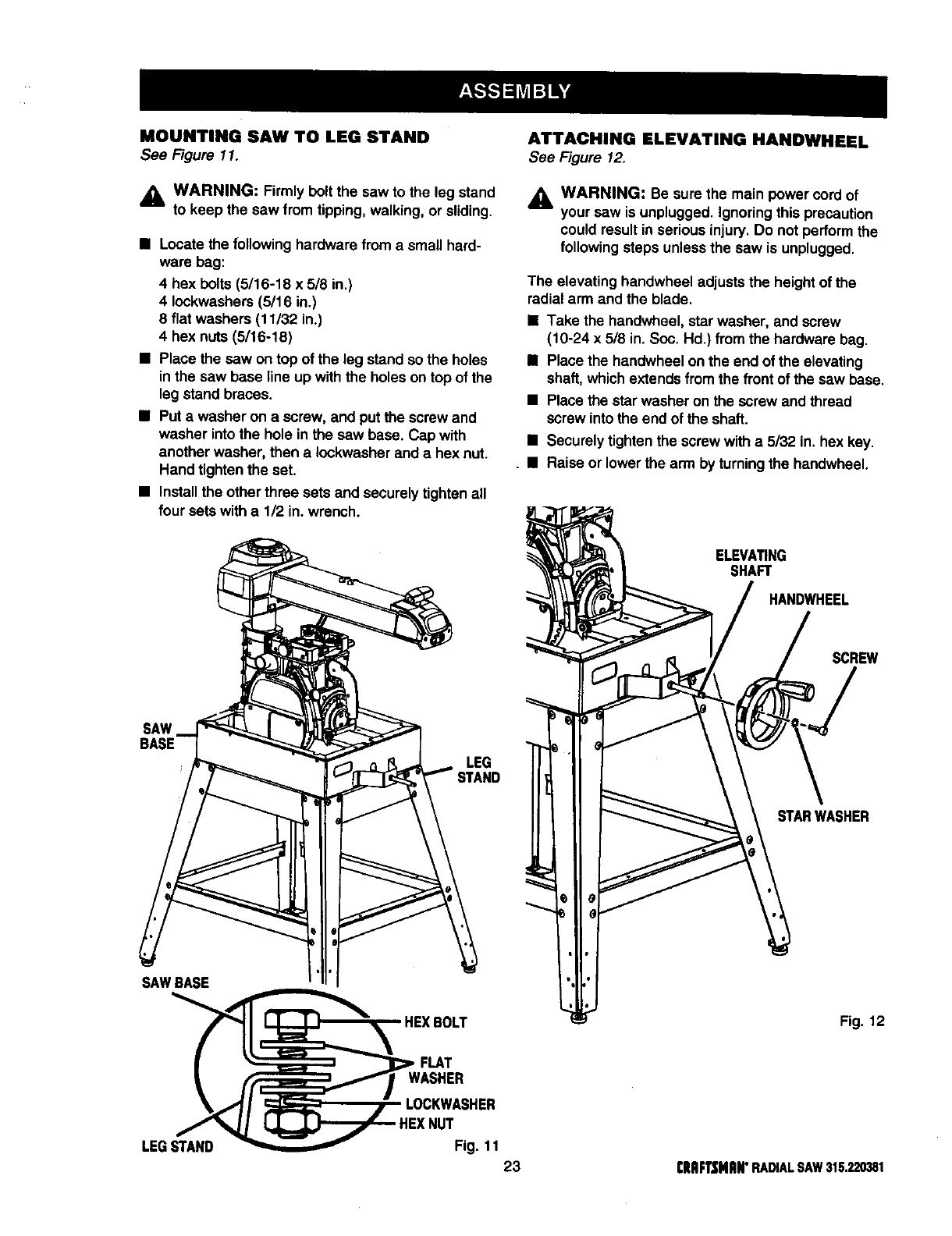
MOUNTING SAW TO LEG STAND
See Figure 11.
,_ WARNING: Firmly boltthe saw to the leg stand
to keep the saw from tipping, walking, or sliding.
•Locate the followinghardware from a small hard-
ware bag:
4 hex bolts (5/16-18 x 5/8 in.)
4 Iockwashers(5/16 in.)
8flat washers (11/32 in.)
4 hex nuts (5/16-18)
•Place the saw on top of the leg stand so the holes
inthe saw base line up with the holes on top of the
leg stand braces.
•Put awasher on a screw, and put the screw and
washer into the hole in the saw base. Cap with
another washer, then a Iockwasherand ahex nut.
Hand tightenthe set.
•Installthe other three sets and securely tighten all
four sets witha 1/2 in. wrench.
ATTACHING ELEVATING HANDWHEEL
See Figure 12.
_, WARNING: Be sure the main power cord of
your saw is unplugged. Ignoringthis precaution
could result in serious injury.Do not performthe
followingsteps unless the saw is unplugged.
The elevating handwheel adjuststhe heightof the
radialarm and the blade.
•Take the handwheel, star washer, and screw
(10-24 x 5/8 in. Soc. Hd.) fromthe hardware bag.
•Place the handwheel onthe end of the elevating
shaft, which extendsfrom the front of the saw base.
•Place the star washer on the screw and thread
screw into the end of the shaft.
•Securely tightenthe screw witha 5132 in. hex key.
•Raise or lower the arm by turningthe handwheel.
ELEVATING
SHAFT
HANDWHEEL
SCREW
SAW
BASE LEG
STARWASHER
SAWBASE i
HEXBOLT
|_ _J_,,FLAT
_1 WASHER
'_,_,*'/I _/" LOCKWASHER
LEGs_HEXNUTFig. 11
23
Fig. 12
[IIQF1]JNIIN"RADIALSAW315.220381
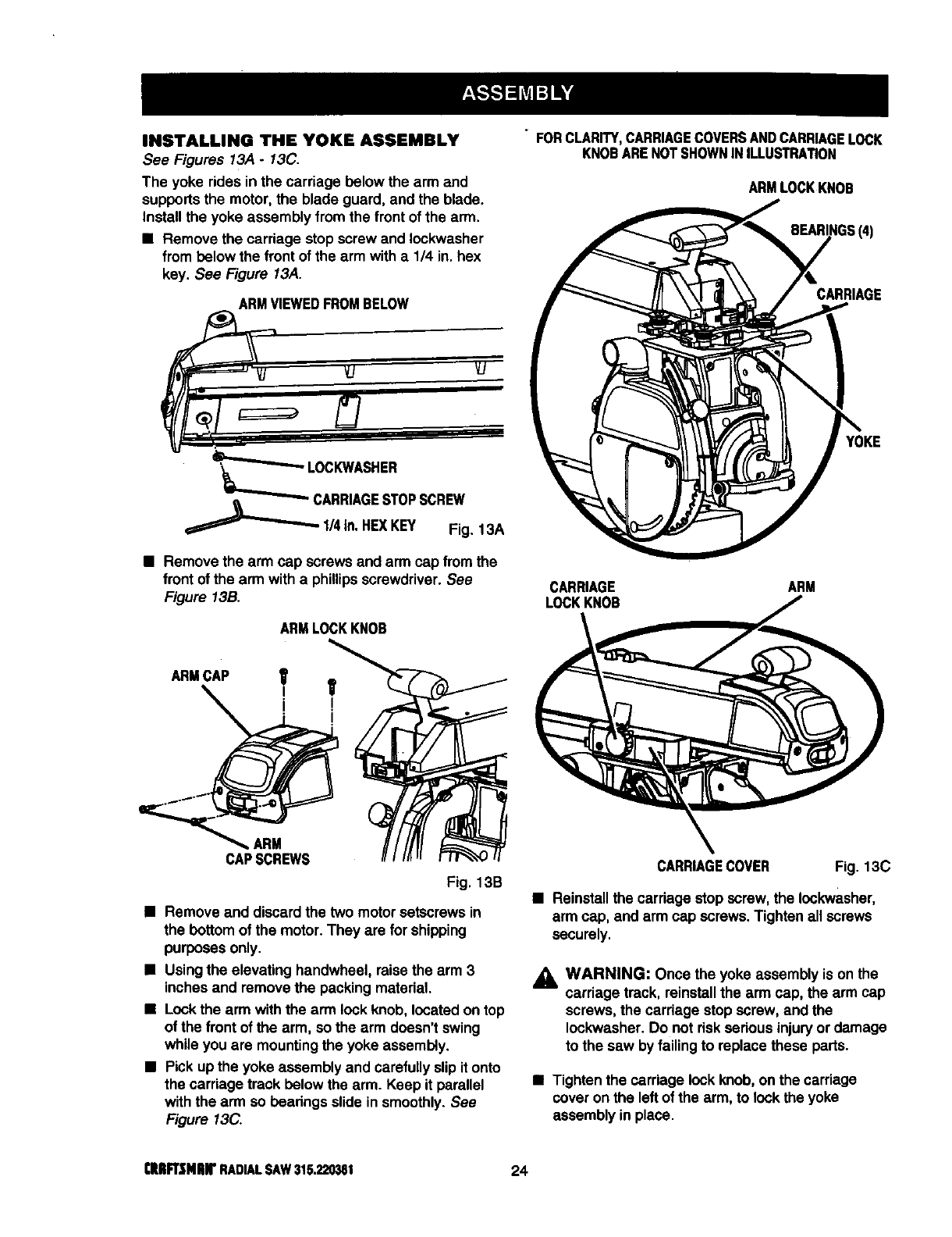
INSTALLING THE YOKE ASSEMBLY
See Figures 13A -13C.
The yoke rides in the carriage below the arm and
supports the motor, the blade guard, and the blade.
Install the yoke assembly from the front of the arm.
•Remove the carriage stop screw and Iockwasher
from below the front of the arm with a 1/4 in. hex
key. See Figure 13A.
ARMVIEWEDFROMBELOW
='_"____._LcOC KWASHER sc.°w
q::==::::===_l,_ , Fig. 13A
•Remove the arm cap screws and arm cap from the
front of the arm witha phillipsscrewdriver. See
Figure 13B.
ARMLOCKKNOB
ARM
CAPSCREWS
Fig. 13B
•Remove and discard the two motorsetscrews in
the bottom of the motor.They are for shipping
purposes only.
•Using the elevating handwheel, raisethe arm 3
inches and remove the packingmaterial.
•Lock the arm withthe arm lockknob, located ontop
of the front of the arm, so the arm doesn't swing
while you are mountingthe yoke assembly.
•Pick up the yoke assembly and carefullyslip it onto
the carriage track below the arm. Keep it parallel
with the arm so bearings slide insmoothly. See
Figure 13C.
• FORCLARITY,CARRIAGECOVERSANDCARRIAGELOCK
KNOBARENOTSHOWNINILLUSTRATION
ARMLOCKKNOB
BEARINGS(4)
CARRIAGE
YOKE
CARRIAGE ARM
LOCKKNOB
CARRIAGECOVER Fig. 13C
•Reinstallthe cardage stop screw,the Iockwasher,
arm cap, and arm cap screws. Tighten all screws
securely.
_1, WARNING: Once the yoke assembly is on the
carriage track, reinstallthe arm cap, the arm cap
screws, the cardage stopscrew, and the
Iockwasher. Do not dsk sedous injury or damage
to the saw by failing to replace these parts.
•Tighten the carriage lockknob, on the carriage
cover on the left of the arm, to lock the yoke
assembly in place.
CIUIFt3MlUf RADIALSAW315.220381 24
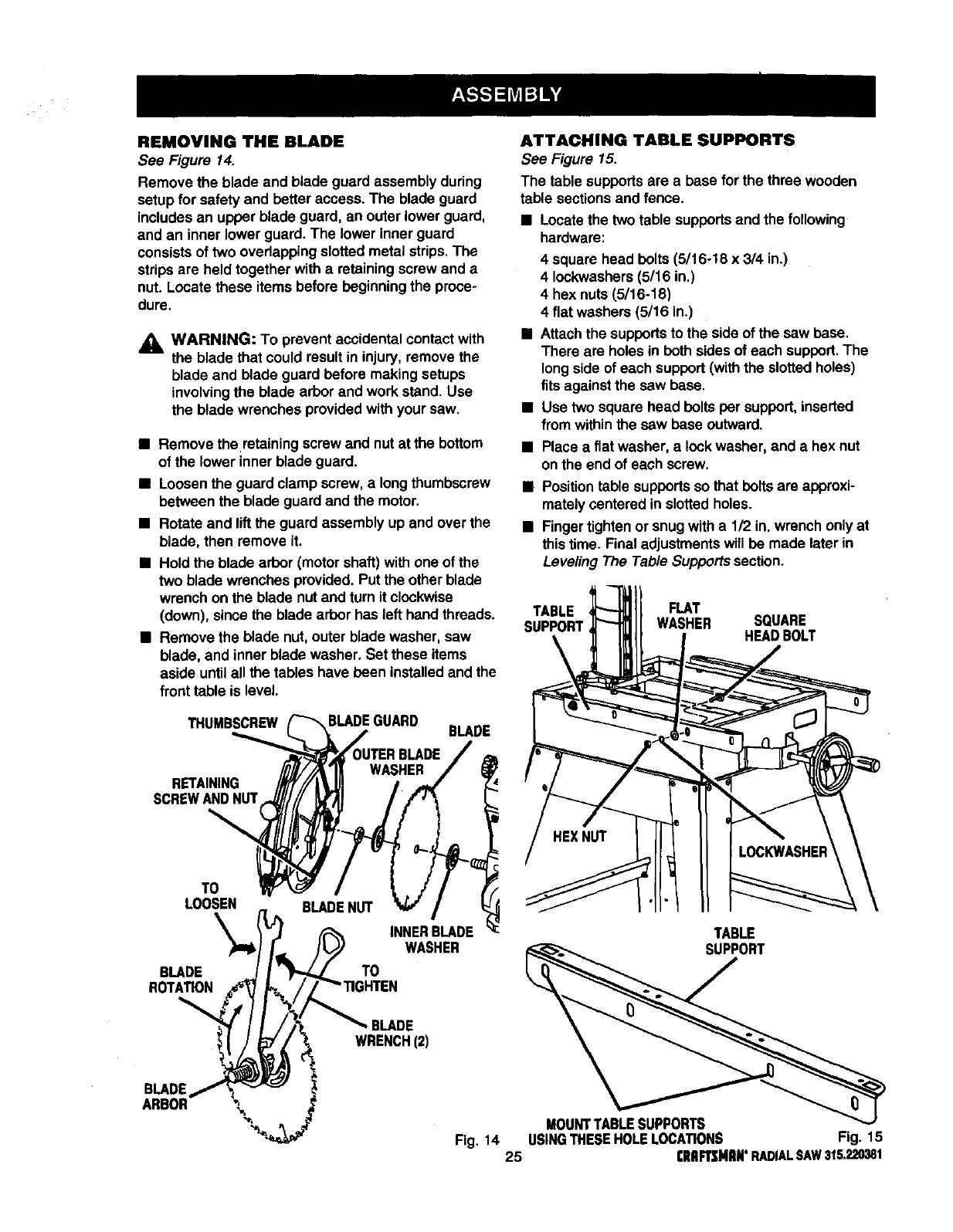
REMOVING THE BLADE
See Figure 14.
Remove the blade and blade guard assembly during
setup for safety and better access. The blade guard
includes an upper blade guard, an outer lower guard,
and an inner lower guard. The lower inner guard
consists of two overlappingslotted metal strips. The
strips are held together with a retaining screw and a
nut. Locate these items before beginningthe proce-
dure.
_, WARNING: To prevent accidental contactwith
the blade that could result in injury, remove the
blade and blade guard before making setups
involvingthe blade arborand work stand. Use
the blade wrenches providedwith your saw.
•Remove the retainingscrew and nutat the bottom
of the lower innerblade guard.
•Loosenthe guard clamp screw,a longthumbscrew
between the blade guard and the motor.
•Rotate and liftthe guard assembly up and over the
blade, then remove it,
•Hold the blade arbor (motor shaft) with one of the
two blade wrenches provided. Put the other blade
wrench on the blade nut and turn it clockwise
(down), since the blade arbor has left hand threads.
•Remove the blade nut, outer blade washer, saw
blade, and inner blade washer, Set these items
aside untilall the tables have been installed and the
front table is level.
THUMBSCREW BLADEGUARD BLADE
RETAINING
SCREWANDNUT
TO
LOOSEN
\
BLADE
ROTATION
TO
INNERBLADE
WASHER
ATTACHING TABLE SUPPORTS
See Figure 15.
The table supports are a base forthe three wooden
table sections and fence.
•Locatethe two table supportsand the following
hardware:
4 square head bolts (5/16o18 x 3/4 in.)
4 Iockwashers(5/16 in.)
4 hex nuts (5/16-18)
4flat washers (5/16 in.)
•Attachthe supportsto the sideof the saw base.
There are holes in both sides of each support.The
longside of each support (withthe slotted holes)
fits against the saw base.
•Use two square head bolts per support,inserted
from withinthe saw base outward.
•Place a flat washer, a lock washer, and a hex nut
onthe end of each screw.
•Positiontable supportsso that bolts are approxi-
mately (;entered in slotted holes.
•Finger tightenor snug with a 112in. wrench only at
thistime. Final adjustmentswill be made later in
Leveling The Table Supports section.
TABLE
SUPPORT
FLAT
WASHER SQUARE
HEADBOLT
TABLE
SUPPORT
BLADE
WRENCH(2)
BLADE
ARBOR
MOUNTTABLESUPPORTS
Fig, 14 USINGTHESEHOLELOCATIONS Fig. 15
25 rRBFTSMIIB°RADIALSAW315.220381
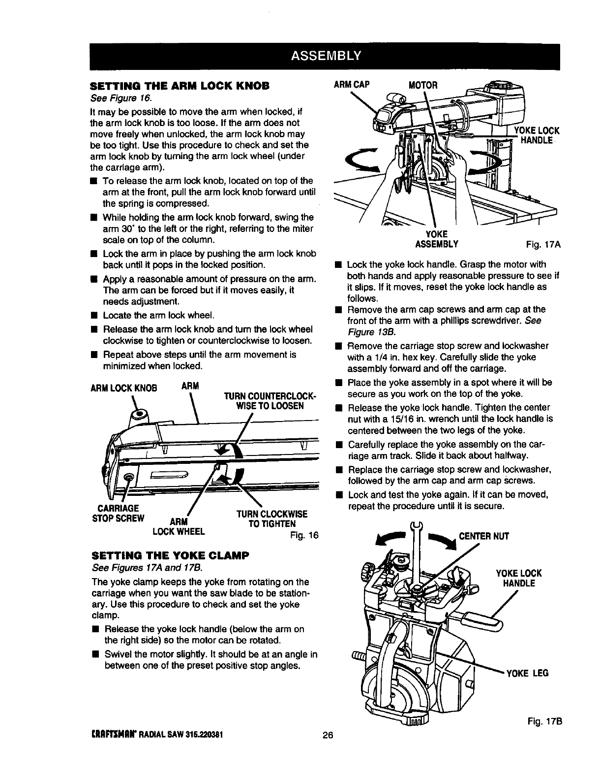
SETTING THE ARM LOCK KNOB
See Figure 16.
It may be possible to move the arm when locked,if
the arm lockknob is too loose. If the arm does not
move freely when unlocked, the arm lockknob may
be too tight. Use this procedure to check and set the
arm lock knob by turning the arm lockwheel (under
the carriage arm).
•To release the arm lock knob,located on topof the
arm at the front, pullthe arm lockknob forward until
the spring is compressed.
•While holdingthe arm lock knob forward, swing the
arm 30" to the left orthe right, referringto the miter
scale on top of the column.
•Lockthe arm in place by pushingthe arm lock knob
back untilit pops in the locked position.
•Apply a reasonable amount of pressureon the arm.
The arm can be forced but if it moves easily, it
needs adjustment.
•Locate the arm lockwheel.
•Release the arm lock knob and turn the lockwheel
clockwise to tighten or counterclockwiseto loosen.
•Repeat above steps untilthe arm movementis
minimizedwhen locked.
ARMLOCKKNOB ARM TURNCOUNTERCLOC_
WISETOLOOSEN
CARRIAGE TURNCLOCKWISE
STOPSCREW ARM TO TIGHTEN
LOCKWHEEL Fig. 16
SETTING THE YOKE CLAMP
See Figures 17,4and 17B.
The yoke clamp keeps the yoke from rotating onthe
carriage when you want the saw blade to be station-
ary. Use this procedure to check and set the yoke
clamp.
•Release the yoke lock handle (below the arm on
the rightside) so the motor can be rotated.
•Swivel the motor slightly.It shouldbe at an angle in
between one of the preset positive stop angles.
ARMCAP MOTOR
YOKELOCK
HANDLE
YOKE
ASSEMBLY Fig. 17A
•Lockthe yoke lock handle. Grasp the motorwith
both hands and apply reasonable pressure to see if
it slips. If it moves, reset the yoke lockhandle as
follows.
•Remove the arm cap screws and arm cap at the
front of the arm witha phillipsscrewdriver.See
Figure 13B.
•Remove the carriage stopscrew and Iockwasher
witha 1/4 in. hex key. Carefully slide the yoke
assembly forward and off the carriage.
•Place the yoke assembly in a spotwhere it will be
secure as you work on the top of the yoke.
•Release the yoke lock handle. Tighten the center
nut with a 15/16 in. wrench untilthe lockhandle is
centered between the two legs of the yoke.
•Carefully replace the yoke assembly on the car-
riage arm track. Slide it back about halfway.
•Replace the carriage stop screw and Iockwasher,
followed by the arm cap and arm cap Screws.
•Lockand test the yoke again. If it can be moved,
repeat the procedureuntil it is secure.
_lil _J_ m_ CENTERNUT
YOKELOCK
HANDLE
LEG
Fig. 17B
tlIAFI_MRIr RADIALSAW315.220381 26
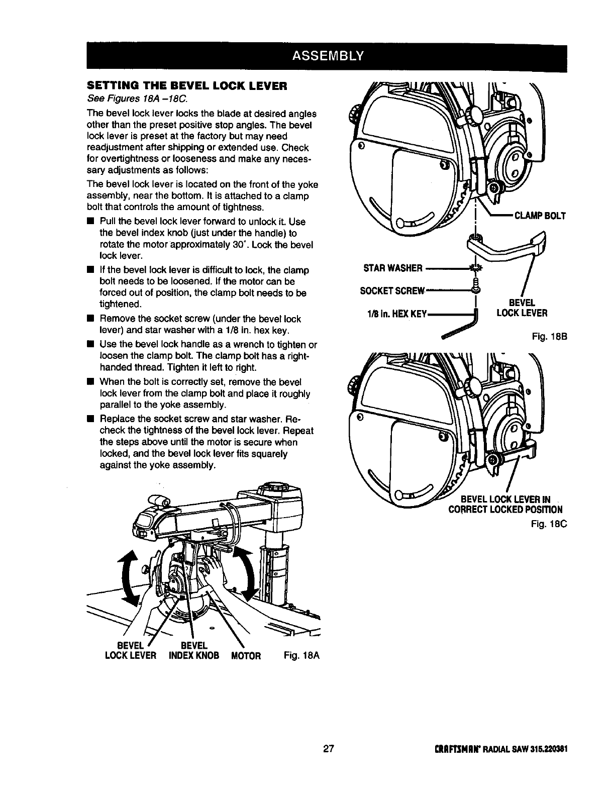
SETTING THE BEVEL LOCK LEVER
See Figures 18A -18C.
The bevel lock lever locksthe blade at desired angles
other than the preset positive stop angles. The bevel
lock lever is preset at the factory but may need
readjustment after shippingor extended use. Check
for overUghtnessor looseness and make any neces-
sary adjustments as follows:
The bevel lock lever is located on the front of the yoke
assembly, near the bottom. It is attached to a clamp
bolt that controlsthe amount of tightness.
•Pull the bevel lock lever forward to unlockit. Use
the bevel index knob (justunder the handle) to
rotate the motor approximately30°. Lock the bevel
lock lever.
•If the bevel lock lever is difficultto lock, the clamp
bolt needs to be loosened. If the motorcan be
forced out of position, the clamp belt needs to be
tightened.
•Remove the socket screw (under the bevel lock
lever) and star washer with a1/8 in. hex key.
•Use the bevel lock handle as awrench to tighten or
loosenthe clamp belt. The clamp bolt has aright-
handed thread. Tighten it left to right.
•When the bolt is correctlyset, remove the bevel
lock lever from the clamp bolt and place it roughly
parallel to the yoke assembly.
•Replace the socket screw and star washer. Re-
check the tightnessof the bevel locklever. Repeat
the steps above untilthe motor is secure when
locked, and the bevel lock lever fits squarely
against the yoke assembly.
STARWASHER
1/8 In.HEXKEY------_
BEVEL
LOCKLEVER
Fig. 18B
BEVELLOCKLEVERIN
CORRECTLOCKEDPosmoN
Fig. 18C
BEVEL BEVEL
LOCKLEVER INDEXKNOB MOTOR Fig. 18A
27 [RIIFTSMIIIr RADIALSAW31S.22_1
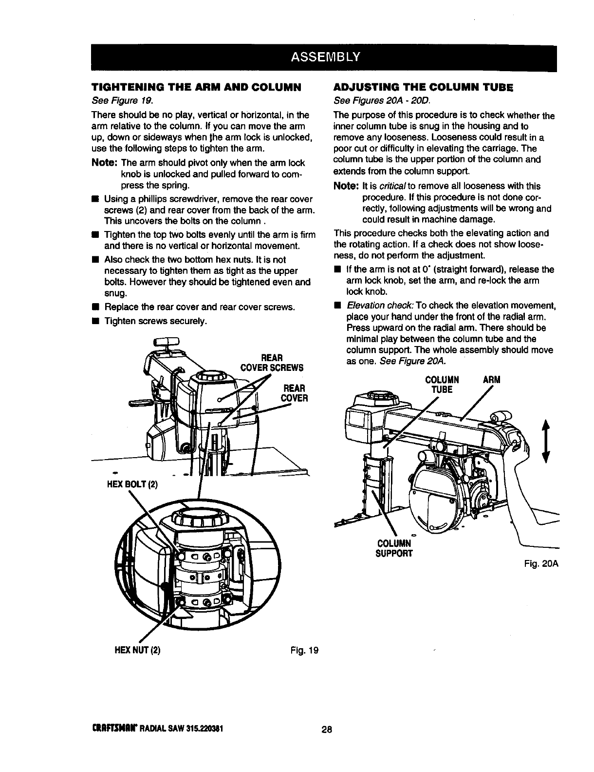
TIGHTENING THE ARM AND COLUMN
See Figure 19.
There should be no play, vertical or horizontal, in the
arm relative to the column. If you can move the arm
up, down or sideways when )he arm lock is unlocked,
use the followingsteps to tightenthe arm.
Note: The arm should pivot only when the arm lock
knob is unlocked and pulled forwardto com-
press the spring.
•Usinga phillipsscrewdriver, remove the rear cover
screws (2) and rear cover from the back of the arm.
This uncoversthe belts on the column.
•Tighten the top two belts evenly untilthe arm is firm
and there is no verticalor horizontalmovement.
•Also check the two bettom hex nuts. It is not
necessary to tightenthem as tight as the upper
bolts. However they should be tightened even and
snug.
•Replace the rear cover and rear cover screws.
•Tighten screws securely.
REAR
COVERSCREWS
REAR
COVER
HEXBOLT(2)
ADJUSTING THE COLUMN TUBE
See Figures 20A -20D.
The purpose of this procedure is to check whether the
inner columntube is snug in the housingand to
remove any looseness. Looseness could resultin a
poor cut or difficultyin elevating the carriage. The
columntube is the upper portion of the columnand
extends fromthe columnsupport.
Note: It is criticalto remove all loosenesswiththis
procedure. If this procedure is not done cor-
rectly,following adjustmentswill be wrongand
couldresult in machine damage.
This procedurechecks beth the elevating actionand
the rotating action. If a check does not show loose-
ness, do not perform the adjustment.
•If the arm is not at O"(straightforward), release the
arm lock knob,set the arm, and re-lock the arm
lockknob.
•Elevationcheck:To check the elevationmovement,
placeyour hand under the frontof the radial arm.
Press upwardon the radialarm. There shouldbe
minimalplay between the column tube and the
column support.The whole assembly shouldmove
as one. See Figure 20A.
COLUMN ARM
TUBE
COLUMN
SUPPORT Fig. 20A
HEXNUT(2) Fig. 19
€IulFrsNlU(' RADIALSAW315.220_1 28
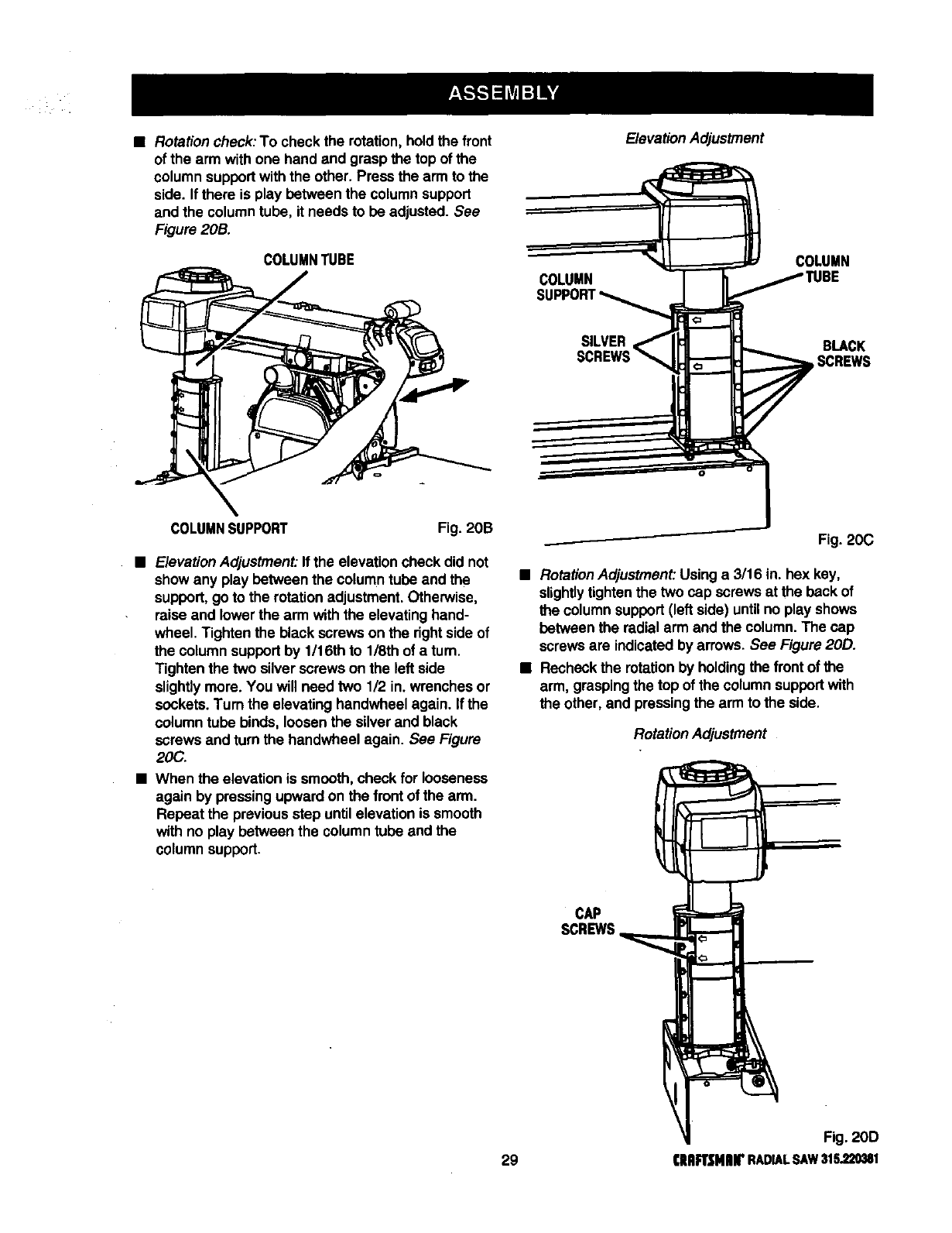
•Rotationcheck:To check the rotation,holdthe front
of the arm with one hand and grasp the top of the
column supportwith the other. Press the arm to the
side. If there is play between the columnsupport
and the columntube, it needs to be adjusted. See
Figure 20B.
COLUMNTUBE
ElevationAdjustment
COLUMN
SILVER
COLUMN
BLACK
SCREWS
COLUMNSUPPORT Fig. 20B
ElevationAdjustment: If the elevation check did not
showany play between the column tube and the
support,go to the rotationadjustment. Otherwise,
raise and lower the arm with the elevating hand-
wheel. Tighten the black screws on the rightside of
the column supportby 1/16th to 1/8th of a turn.
Tighten the two silver screws on the left side
slightlymore. You will need two 1/2 in. wrenches or
sockets.Turn the elevating handwheel again. If the
columntube binds, loosenthe silverand black
screws and turn the handwheel again. See Figure
20C.
•When the elevation is smooth, check for looseness
again by pressing upward on the front of the arm.
Repeat the previous step until elevation is smooth
with no play between the column tube and the
column support.
Fig. 20C
•RotationAdjustment:Usinga3/16in. hex key,
slightlytightenthe two cap screws at the back of
the columnsupport (left side) untilno play shows
between the radial arm and the column.The cap
screws are indicated by arrows. See Figure 20D.
•Recheck the rotationby holdingthe front of the
arm, graspingthe top of the column supportwith
the other, and pressingthe arm to the side,
Rotation Adjustment
CAP
SCREWS
Fig. 20D
29 aRIRSMIU£RADIALSAW315.220381
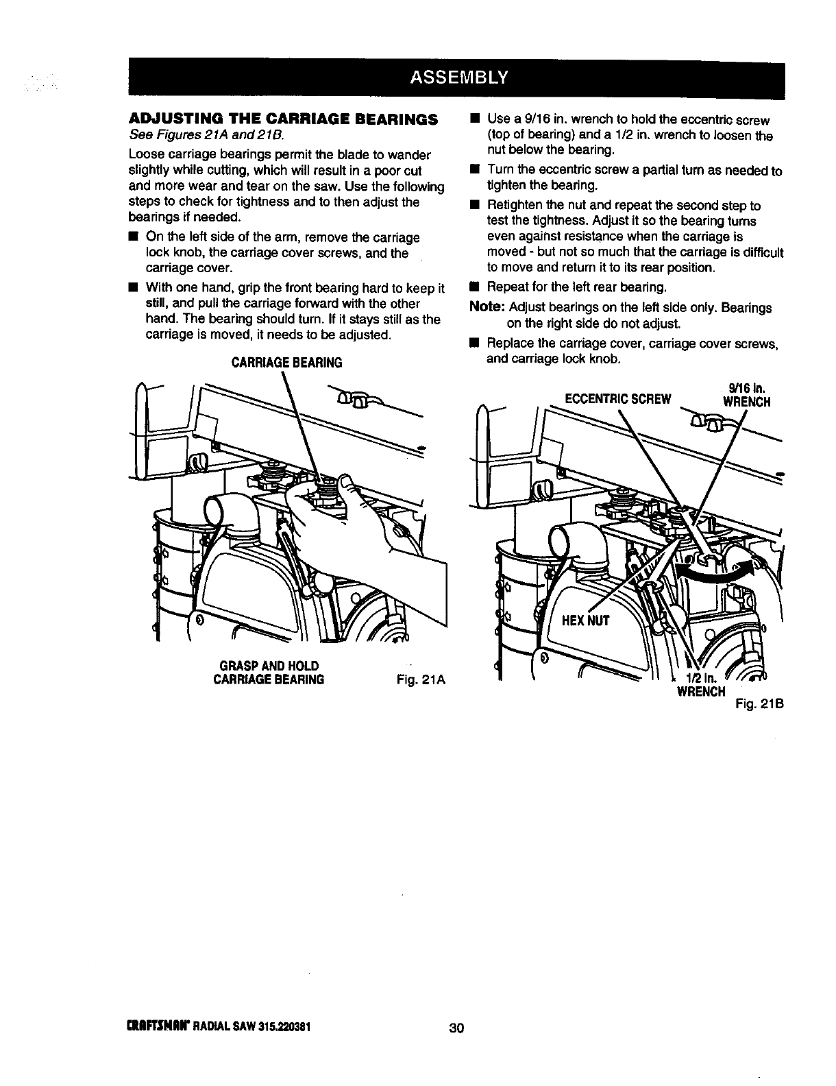
ADJUSTING THE CARRIAGE BEARINGS
See Figures 21A and 21B.
Loose carriage bearings permit the blade to wander
slightly while cutting, which will result in a poorcut
and more wear and tear on the saw. Use the following
steps to check for tightness and to then adjust the
bearings if needed.
•On the left side of the arm, remove the carriage
lock knob, the carriage cover screws, and the
carriage cover.
•With one hand, grip the front bearing hard to keep it
still, and pull the carriage forward withthe other
hand. The bearing shouldturn. If it stays stillas the
carriage is moved, it needs to be adjusted.
CARRIAGEBEARING
•Use a 9/16 in. wrench to holdthe eccentric screw
(top of bearing) and a 1/2 in. wrench to loosen the
nutbelow the bearing.
•Turn the eccentricscrew a partialturn as needed to
tightenthe bearing.
•Retightenthe nut and repeat the second step to
test the tightness. Adjustit so the bearing turns
even against resistance when the carriage is
moved - but notso much that the carriage is difficult
to move and returnit to its rear position.
•Repeat for the left rear bearing.
Note: Adjustbearings on the left side only. Bearings
on the rightsidedo not adjust.
•Replace the carriage cover, carriage cover screws,
and cardage lock knob.
9/16in.
ECCENTRICSCREW WRENCH
GRASPANDHOLD
CARRIAGEBEARING Fig. 21A WRENCH Fig. 21B
C|Al_Nlnr RADIALSAW315.220381 30
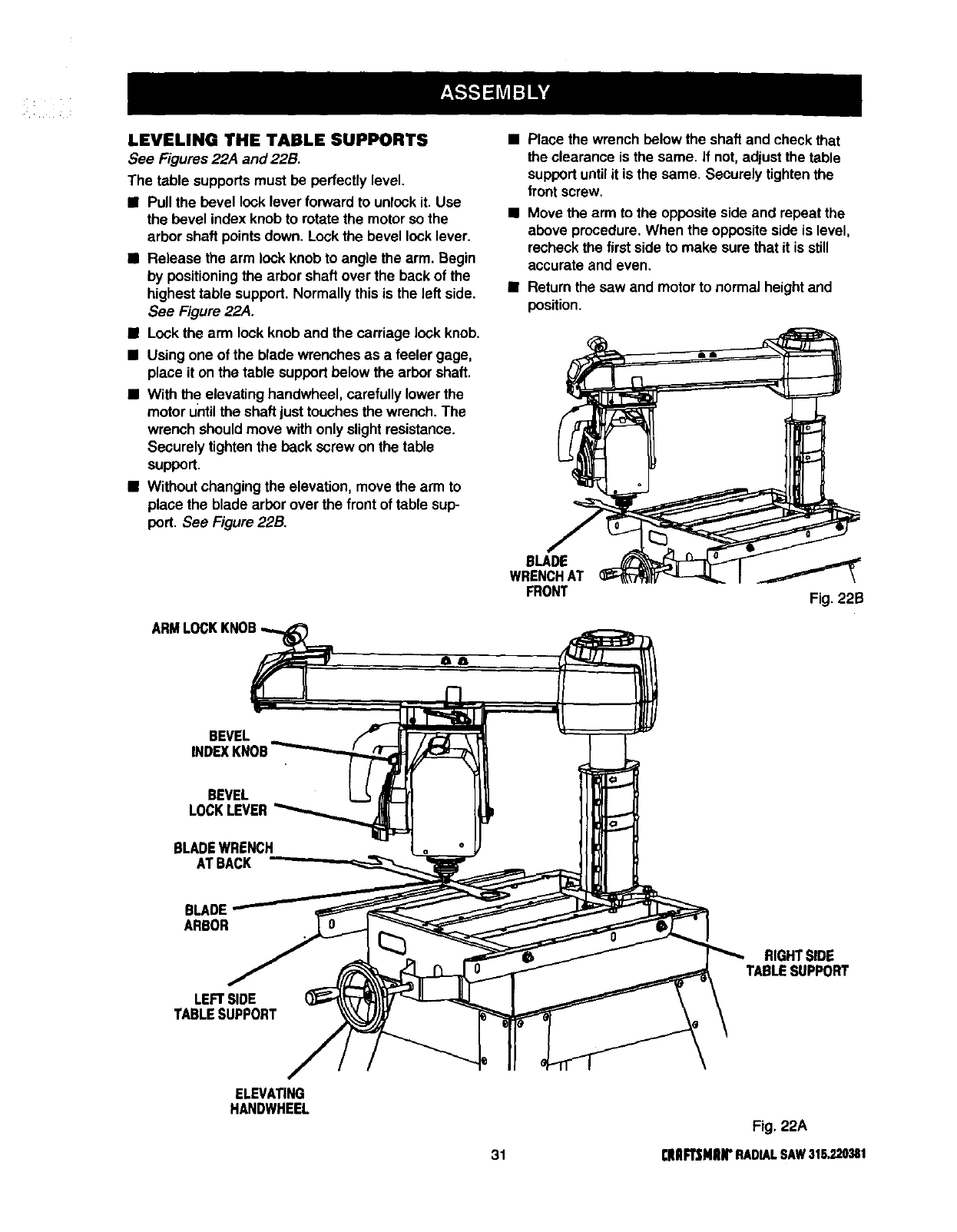
LEVELING THE TABLE SUPPORTS
See Figures 22A and 22B.
The table supportsmust be perfectly level.
•Pull the bevel locklever forward to unlockit. Use
the bevel index knobto rotate the motor so the
arborshaft pointsdown. Lock the bevel lock lever.
•Release the arm lock knob to angle the arm. Begin
by positioningthe arbor shaft over the back of the
highesttable support. Normally this is the left side.
See Figure 22A.
•Lock the arm lock knob and the carriage lockknob.
•Usingone of the blade wrenches as afeeler gage,
place it on the table support below the arbor shaft.
•With theelevating handwheel, carefullylower the
motor untilthe shaftjust touches the wrench. The
wrench should move withonly slightresistance.
Securely tightenthe back screw on the table
support.
•Without changingthe elevation, move the arm to
place the blade arborover the front of table sup-
port. See Figure 22B.
ARMLOCKKNOB
Place the wrench below the shaft and check that
the clearance is the same. If not, adjust the table
supportuntilit is the same. Securely tightenthe
front screw.
Move the arm to the opposite side and repeat the
above procedure. When the opposite side is level,
recheckthe first side to make sure that it is still
accurate and even.
• Return the saw and motor to normal height and
position.
BLADE
WRENCHAT
FRONT Fig. 22B
BEVEL
INDEX KNOB
BEVEL
LOCK LEVER
BLADE WRENCH
AT BACK
BLADE
ARBOR
LEFT SIDE
TABLE SUPPORT
RIGHTSIDE
TABLESUPPORT
ELEVATING
HANDWHEEL
Fig. 22A
31 [RRF1_NRrRADIALSAW315.220381
INSTALLING THE FRONT TABLE
See Figures 23A -23C.
Use this procedure to installthe fixed front table.
The top of the table has counterbored holes, predrilled
from the top, around the center to attach the table. In
the center are a counterbored hole and asmall hole,
which is not counterbored. They are used for raising
or lowering the center of the table until it is level.
•Locate the front table and the followinghardware:
1 tee nut
1 U-clip (1/4 in.)
1 setscrew (1/4-20 x 7/8 in.)
4 pan head screws (1/4-20 x 1 in.)
1 pan head screw (1/4-20 x 1-3/4 in.)
5 flat washers (5/8 in.)
4 lock washers (1/4 in.)
4 hex nuts(1/4-20)
•Place the front table on a solidworksurface,with
the top surface face down. Race the tee nut inthe
non-counterboredhole and tap it in place witha
hammer.
U-CLIP AUGNU-CUP
OVERTHISHOLE
SAWBASE
Fig. 23B
•Place the long pan head screw into the center hole
and thread into the U-clip. Do nottighten untilthe
SETSCREW table has been checked for evenness. See Figure
_SCREW 23A.
f_l _'_._,_ FLAT •Place the setscrew throughthe small leveling hole
r I _WASHER and thread intothe tee nut, butdo not tighten.
ol ___ _k • Put a1 in. long pan head screw in the four remain-
ing holes and throughthe holes inthe support.
Cap with a lock washer and hex nut. Tighten with a
7/16 in. wrench and phillipsscrewdriver. This
REAROF completes installationof the front table.
1-3/4in.SCREW/|
SCREW L!'I /ELAT
]_' T' ' WASHER
- i
REAROFFRONTTABLE Fig. 23A
•Snap the U-clip onto the front edge of the saw
base. Line up the hole inthe U-clip withthe saw
base hole justto the left of the center notch in saw
base. See Figure 23B.
•Place the table, top up, on the table supportsso the
center counterboredhole lines up over the hole in
the U-clip.
•Place a flat washer in each counterborsdhole. LOCKWASHER
HEXNUT
Fig. 23C
[|lll_NlUr RADIALSAW315.220381 32
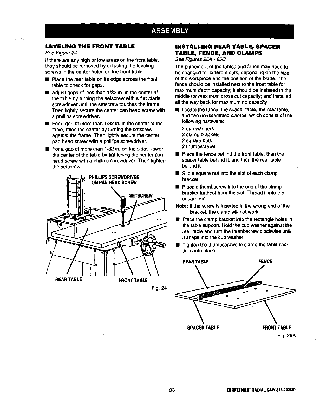
LEVELING THE FRONT TABLE
See Figure 24.
If there are any high or low areas on the front table,
they should be removed by adjustingthe leveling
screws in the center holes on the front table.
•Place the rear table on its edge across the front
table to check for gaps.
•Adjust gaps of less than 1/32 in. in the center of
the table by turningthe setscrew with a flat blade
screwdriver untilthe setscrew touches the frame.
Then lightly secure the center pan head screw with
a phillipsscrewdriver.
•For a gap of more than 1/32 in. in the center of the
table, raise the center by turningthe setscrew
against the frame. Then lightlysecure the center
pen head screw with a phillipsscrewdriver.
BFor a gap of more than 1/32 in. on the sides, lower
the center of the table by tighteningthe center pan
head screw with a phillipsscrewdriver.Then tighten
the setscrew.
PHILLIPSSCREWDRIVER
ONPANHEADSCREW
SETSCREW
REARTABLE FRONTTABLE
Fig. 24
INSTALLING REAR TABLE, SPACER
TABLE, FENCE, AND CLAMPS
See Figures 25A -25C_
The placement of the tables and fence may need to
be changed for differentcuts, depending on the size
of the workpiece and the positionof the blade. The
fence should be installed next to the front table for
maximum depth capacity; it should be installed inthe
middle for maximum cross cut capacity; and installed
all the way back for maximum rip capacity.
BLocate the fence, the spacer table, the rear table,
and two unassembledclamps, which consistof the
following hardware:
2cup washers
2 clamp brackets
2square nuts
2 thumbscrews
•Place the fence behind the front table, then the
spacer table behind it,and then the rear table
behind it,
•Slip a square nut intothe slotof each clamp
bracket.
BPlace a thumbscrewintothe end of the clamp
bracketfarthest from the slot. Thread it intothe
square nut.
Note: If the screw is inserted inthe wrongend of the
bracket, the clampwill not work.
•Place the clamp bracketinto the rectangle holes in
the table support.Hold the cupwasher againstthe
rear table and turn the thumbscrewclockwiseuntil
it snaps into the cup washer.
•Tighten the thumbscrews to clamp the table sec-
tions intoplace.
REARTABLE FENCE
SPACERTABLE FRONTTABLE
Fig. 25A
33 rRIIR'SMmN"RADIALSAW$1S,220,_1
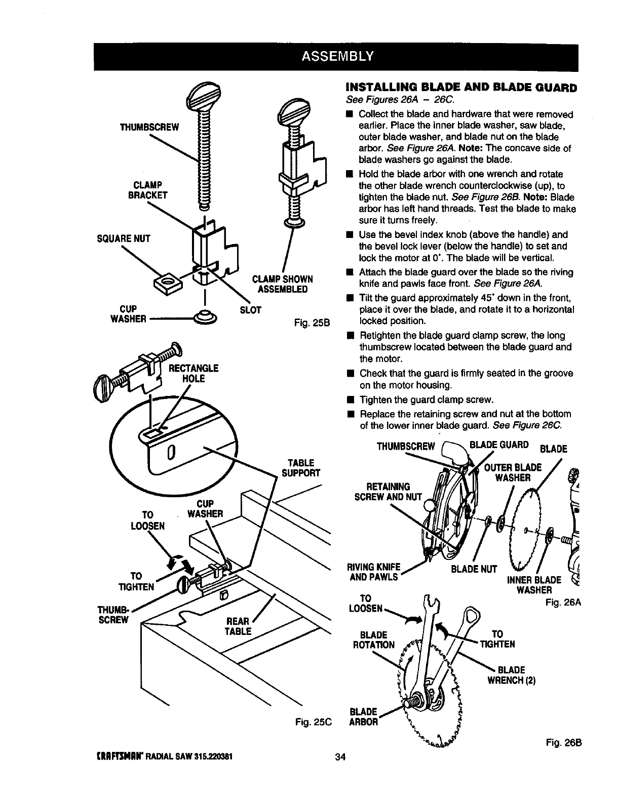
THUMBSCREW
CLAMP
BRACKET
SQUARENUT
CLAMPSHOWN
iASSEMBLED
CUP
WASHER-------.-_ SLOT
Fig. 25B
HOLE
TABLE
SUPPORT
CUP
TO
LOOSEN
TO
TIGHTEN
SCREW
INSTALLING BLADE AND BLADE GUARD
See Figures 26,4 -26C.
•Collect the blade and hardware that were removed
earlier. Place the inner blade washer, saw blade,
outer blade washer, and blade nut on the blade
arbor. See Figure 26,4. Note: The concave side of
blade washers go against the blade.
•Hold the blade arbor with one wrench and rotate
the other blade wrench counterclockwise (up), to
tighten the blade nut. See Figure 26B. Note: Blade
arbor has left hand threads. Test the blade to make
sure it turns freely.
•Use the bevel index knob (above the handle) and
the bevel lock lever (below the handle) to set and
lock the motor at 0". The blade will be vertical.
•Attach the blade guard over the blade so the riving
knife and pawls face front. See Figure 26,4.
•Tilt the guard approximately 45" down in the front,
place it over the blade, and rotate itto a horizontal
locked position.
•Retighten the blade guard clamp screw, the long
thumbscrew located between the blade guard and
the motor.
•Check that the guard is firmly seated in the groove
on the motor housing.
•Tighten the guard clamp screw.
•Replace the retaining screw and nut at the bottom
of the lower inner blade guard. See Figure 26C.
THUMBSCREW BLADEGUARD BLADE
RETAINING
BCREWAND NUT
RIVING KNIFE
AND PAWLS
TO
BLADE
ROTATION
BLADE NUT INNERBLADE
WASHER
Fig. 26A
TO
;HTEN
BLADE
WRENCH(2)
[RAR3MIIIrRADIALSAW315.220381
BLADE
Fig. 25C
34
Fig. 26B
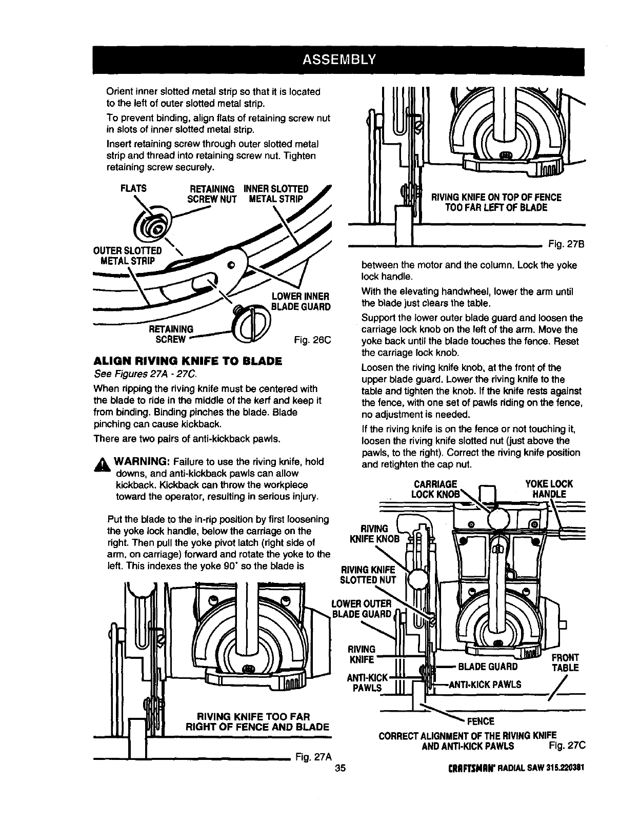
Orient inner slotted metal stdpso that it is located
to the left of outer slotted metal strip.
To prevent binding, align flats of retaining screw nut
in slotsof inner slottedmetal strip.
Insert retaining screw through outer slotted metal
stdp and thread into retaining screw nut. Tighten
retaining screw securely.
FLATS
W NUT
OUTERSLOTTED \
METAL STRIP
RETAINING INNERSLOTTED
METALSTRIP
X
LOWERINNER
_BLADE GUARD
RETAINING ( IIJ/
SCREW"--- _ Fig. 26C
ALIGN RIVING KNIFE TO BLADE
See Figures 27A -27C.
When rippingthe rivingknife must be centered with
the blade to ride in the middle of the kerf and keep it
from binding. Bindingpinches the blade. Blade
pinchingcan cause kickback.
There are two pairs of anti-kickback pawls.
_1 WARNING: Failure to use the dying knife, hold
downs, and anti-kickbackpawls can allow
kickback. Kickback can throw the workpiece
toward the operator, resultingin serious injury.
Put the blade to the in-dppositionby first loosening
the yoke lock handle, below the cardage on the
dght. Then pullthe yoke pivot latch(right side of
arm, on carriage) forward and rotatethe yoke to the
left. This indexesthe yoke 90°so the blade is
RIVINGKNIFEONTOPOFFENCE
TOOFARLEFTOFBLADE
Fig. 27B
between the motor and the column. Lockthe yoke
lock handle.
With the elevating handwheel, lower the arm until
the blade just clears the table.
Supportthe lower outer blade guard and loosen the
carriage lockknob on the left of the arm. Move the
yoke back untilthe blade touches the fence. Reset
the carriage lockknob.
Loosenthe rivingknife knob,at the front of the
upper blade guard. Lowerthe rivingknife to the
table and tightenthe knob. If the knife rests against
the fence, with one set of pawls dding on the fence,
no adjustmentis needed.
If the rivingknife is on the fence or not touchingit,
loosen the dving knifeslotted nut (justabove the
pawls, to the right). Correct the dvingknife position
and retightenthe cap nut.
CARRIAGE YOKE LOCK
:HANDLE
RIVING
RIVING
KNIFE FRONT
TABLE
RIGHT OF FENCE AND BLADE
Fig. 27A 35
FENCE
CORRECTALIGNMENTOFTHERIVINGKNIFE
ANDANTI-KICKPAWLS Fig. 27C
CRAFTSMAN"RADIAL SAW 315.220381
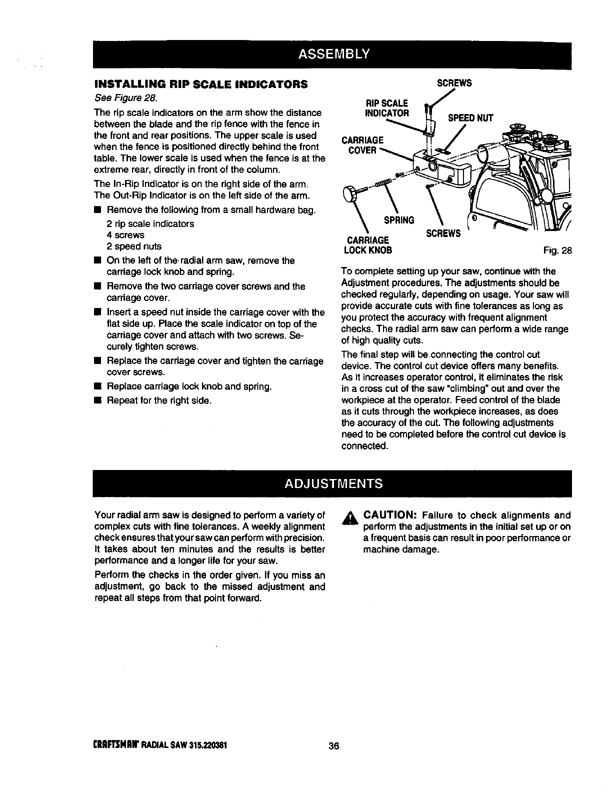
INSTALLING RIP SCALE INDICATORS
See Figure 28,
The rip scale indicatorson the arm show the distance
between the blade and the rip fence with the fence in
the front and rear positions.The upper scale is used
when the fence is positioneddirectly behind the front
table. The lower scale is used when the fence is at the
extreme rear, directlyin front of the column,
The In-Rip Indicatoris on the rightside of the arm.
The Out-Rip Indicator is on the left side of the arm,
•Remove the followingfrom a small hardware bag.
2 rip scale indicators
4 screws
2 speed nuts
• On the left of theradial arm saw, removethe
carriage lock knob and spring.
•Remove the two carriage cover screws and the
carriage cover.
•Insert a speed nut insidethe carriage cover withthe
flat side up. Place the scale indicatoron top of the
carriage coverand attach withtwo screws. Se-
curely tightenscrews.
•Replace the carriage cover and tightenthe carriage
cover screws.
•Replace carriage lockknob and spring.
•Repeat for the rightside.
RIP SCALE
INDICATOR
CARRIAGE
SCREWS
SPEEDNUT
SPRING
CARRIAGE
LOCKKNOB
SCREWS
Fig. 28
To complete setting up your saw, continue withthe
Adjustment procedures.The adjustmentsshould be
checked regularly, depending on usage. Your saw will
provide accurate cuts withfine tolerancesas longas
you protectthe accuracy with frequent alignment
checks. The radialarm saw can performa wide range
of highquality cuts.
The final step will be connecting the control cut
device. The control cut device offers many benefits.
As it increases operator control, it eliminates the risk
in a cross cut of the saw "climbing" out and over the
workpiece at the operator. Feed control of the blade
as it cuts through the workplace increases, as does
the accuracy of the cut. The following adjustments
need to be completed before the control cut device is
connected.
Your radial arm saw is designed to perform a variety of
complex cuts with fine tolerances. A weekly alignment
check ensuresthat your sawcan performwithprecision.
It takes about ten minutes and the results is batter
performance and a longer life for your saw.
Perform the checks in the order given. If you miss an
adjustment, go back to the missed adjustment and
repeat all steps from that pointforward.
_, CAUTION: Failure to check alignments and
performthe adjustmentsin the initialset up or on
afrequent basiscan result in poorperformanceor
machine damage.
r'RARYMAN'RADIALSAWS15,320381 36
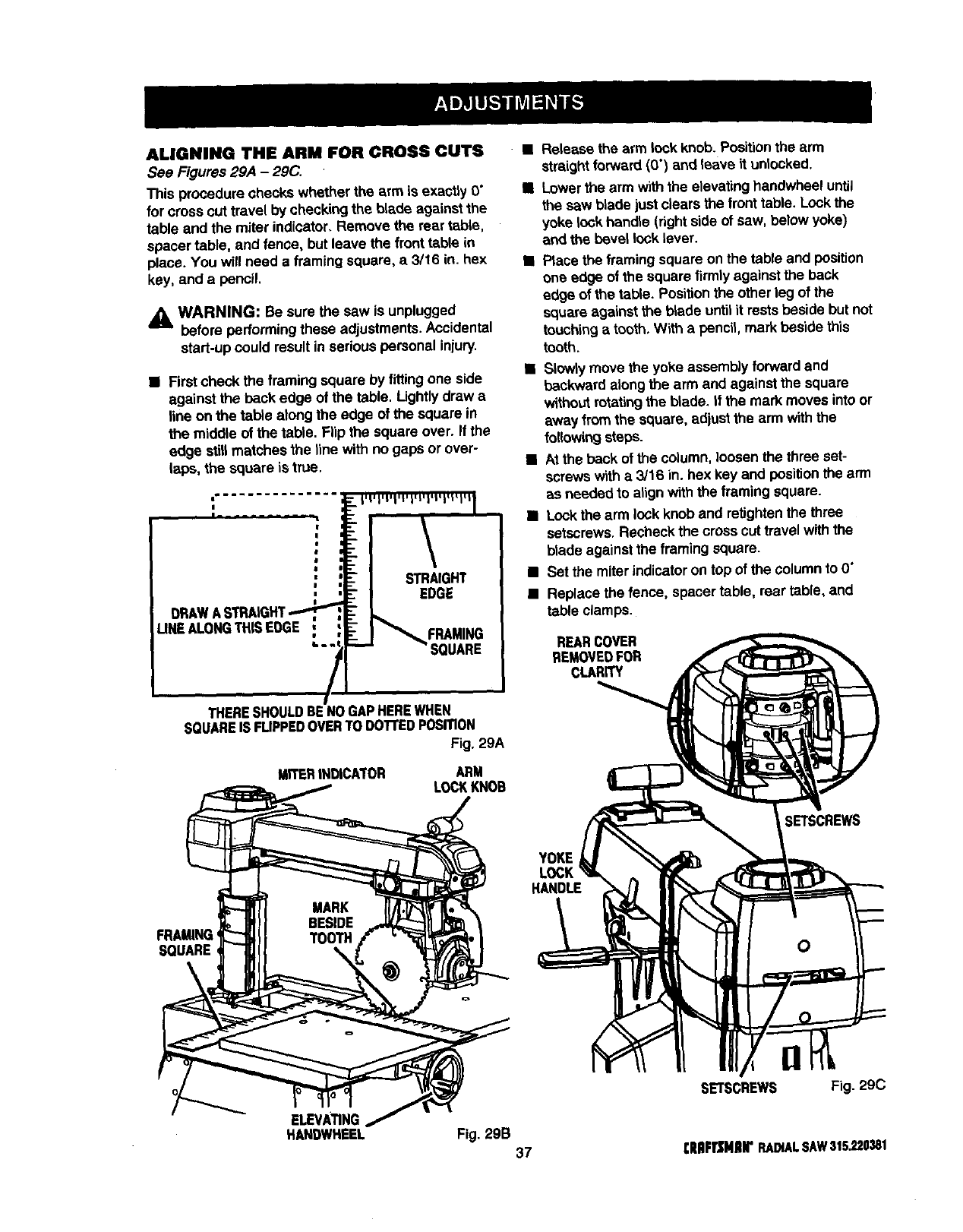
ALIGNING THE ARM FOR CROSS CUTS
See Figures 29,4 -2gC,
This procedure checks whether the arm is exscfiy O"
for crosscut travel by checking the blade against the
table and the miter indicator. Remove the rear table,
spacer table, and fence, but leave the front ta_e in
place. You will need a framing square, a 3/16 in. hex
key, and a pencil,
_k WARNING: Be sure the saw is unplugged
before performingthese adjustments. Accidental
start-up could result in serious personal injury.
•First check the framing square by fitting one side
against the back edge of the table. Lightlydraw a
line on the table along the edge of the square in
the middle of the table. Flip the square over. If the
edge still matches the line with no gaps or over-
tape, the square is true.
THERESHOULDBENOGAPHEREWHEN
SQUAREIS FUPPEDOVERTODOTrEDPOSITION
Fig. 29A
MITERINDICATOR ARM
LOCKKNOB
FRAMING
SQUARE \
Release the arm lock knob. Positionthe arm
straightforward (0") and leave it unlocked.
Lowerthearm withtheelevatinghandwheeluntil
the saw blade just clears the fronttable. Lockthe
yoke lockhandle (rightside of saw, below yoke)
and the bevel lock Lever.
•Place the framingsquare on the table and position
one edge of the square firmly against the back
edge of the table, Positionthe other leg of the
square against the blade untilit rests beside but not
touchingatooth. With a pencil, mark beside this
tooth.
•Slowlymove the yoke assembly forward and
backward alongthe arm and against the square
without rotatingthe blade. If the mark moves into or
away fromthe square, adjust the arm withthe
followingsteps.
•At the back of the column, loosenthe three set-
screws w_tha 3/16 in. hex key and positionthe arm
as needed to align withthe framing square.
•Lockthe arm lock knob and retightenthe three
setscrews. Recheck the cross cut travel with the
blade against the framing square.
• Set the miterindicatoron top of the columnto O"
•Replace the fence, spacer table, rear table, and
table clamps.
REARCOVER
REMOVEDFOR
CLARITY
Y_E
LOCK
H_O_
SETSCREWS Fig. 29C
ELEVAnNG
HANDWHEEL Fig. 29B 37 CRIIFTZNIIrRADIALSAW315.220381
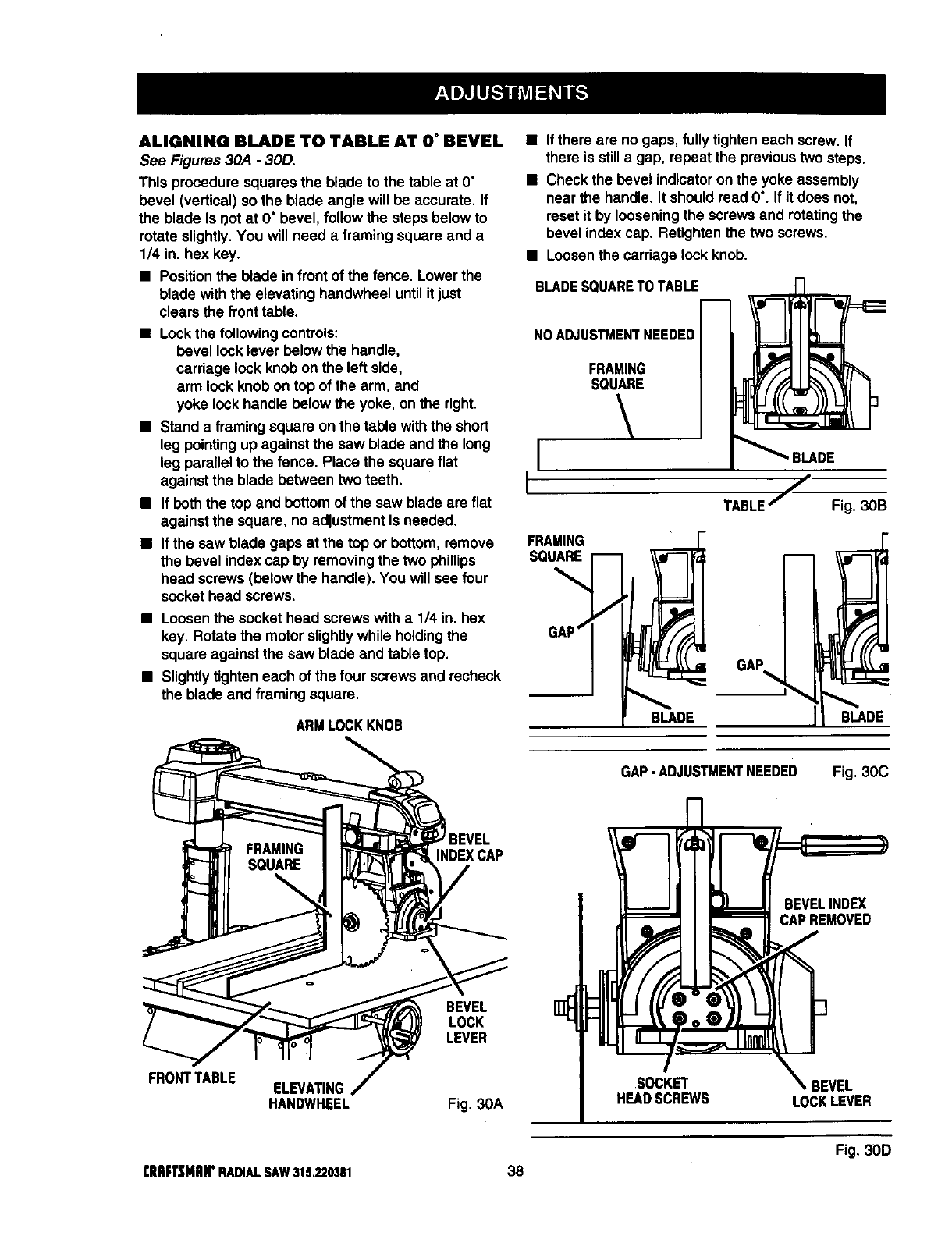
ALIGNING BLADE TO TABLE AT 0°BEVEL
See Figures 30A -30D.
This procedure squares the blade to the table at O"
bevel (vertical) so the blade angle will be accurate. If
the blade is r_otat O"bevel, follow the steps below to
rotate slightly.You will need a framing square and a
1/4 in. hex key.
•Positionthe blade in front of the fence. Lower the
blade withthe elevating handwheel untilit just
clears the fronttable.
•Lockthe followingcontrols:
bevel lock lever below the handle,
carriage lock knob on the left side,
arm lock knob on top of the arm, and
yoke lockhandle below the yoke, on the right.
•Stand a framing square on the table with the short
leg pointingup against the saw blade and the long
leg parallel to the fence. Place the square flat
against the blade between two teeth.
•If boththe top and bottom of the saw blade aN flat
against the square, no adjustment is needed.
•If the saw blade gaps at the top or bottom, remove
the bevel index cap by removing the two phillips
head screws (below the handle). You will see four
socket head screws.
•Loosenthe socket head screws with a 1/4 in. hex
key. Rotate the motor slightlywhile holdingthe
square against the saw blade and table top.
•Slightlytighten each of the four screws and recheck
the blade and framing square.
ARMLOCKKNOB
•If there are no gaps, fully tighten each screw. If
then is stilla gap, repeat the previoustwo steps.
•Check the bevel indicatoronthe yoke assembly
near the handle. It should read 0% If it does not,
reset it by looseningthe screws and rotatingthe
bevel index cap. Retighten the two screws.
•Loosenthe carriage lock knob.
BLADESQUARETO TABLE
NOADJUSTMENTNEEDED
FRAMING
SQUARE
FRAMING
SQUARE
BLADE
TABLE/Fig. 3OB
GAP
BLADE
FRONTTABLE
INDEXCAP
BEVEL
LOCK
LEVER
ELEVATING
HANDWHEEL Fig. 3OA
GAP-ADJUSTMENTNEEDED
m
41 ¸
41
SOCKET
HEADSCREWS
Fig. 3OC
BEVELINDEX
CAPREMOVED
_BEVEL
LOCKLEVER
Fig. 30D
ClIIIFTSMJlrRADIALSAW315.220381 38
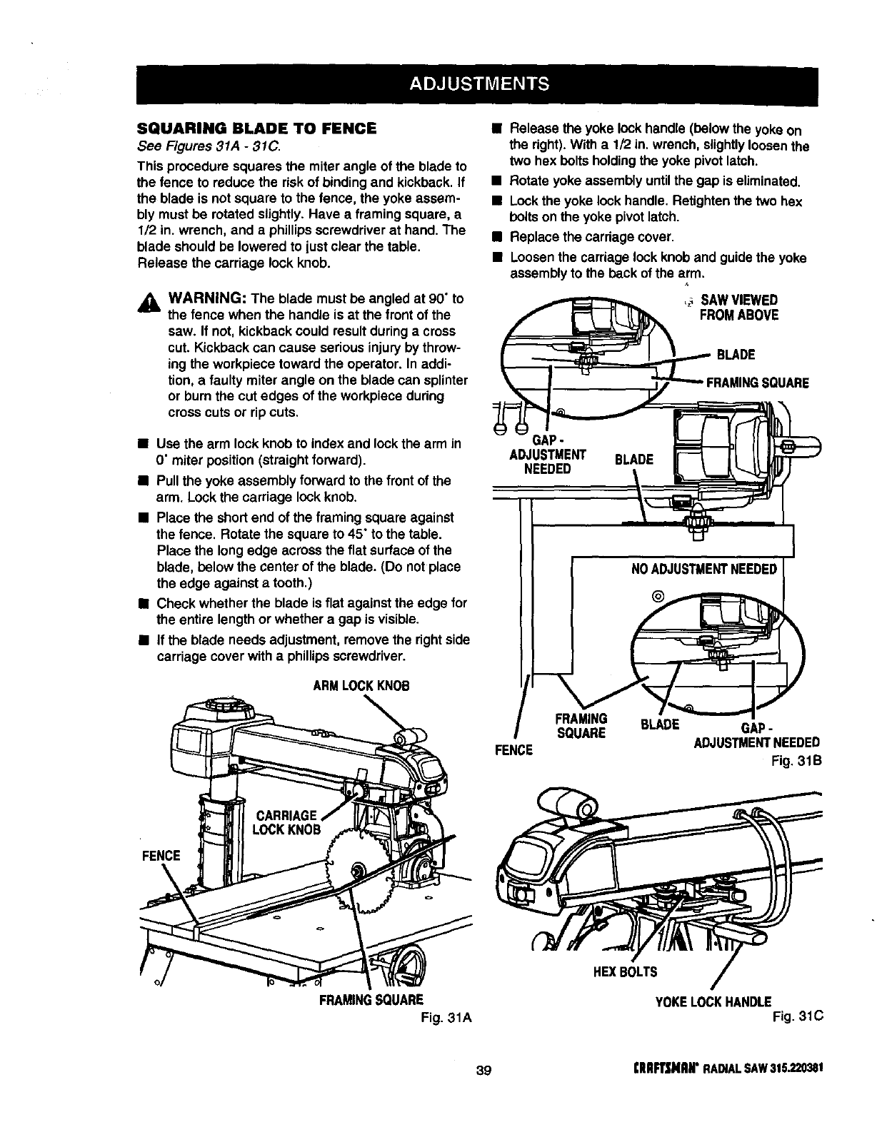
SQUARING BLADE TO FENCE
See Figures 31A -31C.
This procedure squares the miter angle of the blade to
the fence to reduce the riskof bindingand kickback. If
the blade is not square to the fence, the yoke assem-
bly must be rotated slightly. Have a framing square, a
1/2 in. wrench, and a phillips screwdriverat hand. The
blade should be lowered to justclear the table.
Release the carriage lock knob.
,_ WARNING: The blade must be angled at 90" to
the fence when the handle is at the frontof the
saw. If not, kickback could result duringa cross
cut. Kickback can cause serious injuryby throw-
ing the workpiece toward the operator. In addi-
tion, a faulty miter angle on the blade can splinter
or burnthe cut edges of the workpiece during
cross cuts or rip cuts.
•Use the arm lock knob to index and lock the arm in
O"miter position (straight forward).
•Pull the yoke assembly forward to the front of the
arm. Lockthe carriage lock knob.
•Place the short end of the framing square against
the fence. Rotate the square to 45" to the table.
Place the long edge acrossthe flat surface of the
blade, below the center of the blade. (Do not place
the edge against a tooth.)
•Check whether the blade is flat against the edge for
the entire length or whether a gap is visible.
•If the blade needs adjustment, remove the rightside
carriage cover with a phillipsscrewdriver.
ARMLOCKKNOB
FENCE
FRAMINGSQUARE
Fig. 31A
•Release the yoke lock handle (below the yoke on
the right). With a 1/2 in. wrench,slightlyloosenthe
two hex bolts holdingthe yoke pivot latch.
• Rotate yoke assembly untilthe gap is eliminated.
•Lockthe yoke lock handle. Retightenthe two hex
boltson the yoke pivotlatch.
•Replace the carriagecover.
•Loosenthe carriage lockknob and guidethe yoke
assemblyto the back of the arm.
FS'oW%W ,
BLADE
RAMINGSQUARE
NOADJUSTMENTNEEDED
FENCE
FRAMING BLADE
SQUARE GAP-
ADJUSTMENTNEEDED
Fig, 31B
HEXBOLTS
YOKELOCKHANDLE
Fig. 31C
39 (RlU:t3NIIIr RADIALSAW315.220381
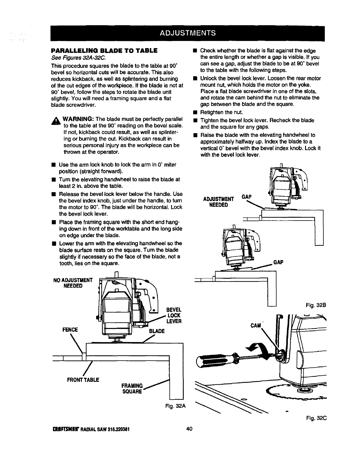
PARALLELING BLADE TO TABLE
See Figures 32A-32C.
This procedure squares the blade to the table at 90"
bevel so horizontalcuts will be accurate. This also
reduces kickback, as well as splinteringand burning
of the cut edges of the workpiece. If the blade is not at
90" bevel, follow the steps to rotate the blade unit
slightly.You will need a framing square and a flat
blade screwdriver.
_k WARNING: The blade must be perfectly parallel
to the table at the 90" reading on the bevel scale,
If not, kickbackcould result,as well as splinter-
ing or burningthe cut. Kickback can result in
serious personal injuryas the workpiece can be
thrown at the operator.
•Use the arm lock knobto lock thearm in 0° miter
position(straightforward).
•Turn the elevating handwheel to raisethe blade at
least 2 in. above the table.
Release the bevel lock lever below the handle. Use
the bevel index knob, just under the handle, to turn
the motor to 90". The blade will be horizontal. Lock
the bevel lock lever.
•Place the framing square withthe short end hang-
ing down in front of the worktableand the longside
on edge underthe blade.
•Lower the arm withthe elevating handwheel so the
blade surface rests on the square. Turn the blade
slightlyif necessary so the face of the blade, nota
tooth, lieson the square.
NOADJUSTMENT
NEEDED
FENCE
BEVEL
LEVER
BLADE
FRONTTABLE FRAMING
SOUARE
Fig. 32A
•Check whether the blade is fiat against the edge
the entire lengthor whether a gap is visible. If you
can see a gap, adjustthe blade to be at 90" bevel
to the table with the followingsteps.
•Unlockthe bevel locklever. Loosenthe rear motor
mount nut, which holdsthe motor on the yoke,
Place a flat blade scrawddver inone of the slots,
and rotatethe cam behind the nutto eliminatethe
gap betweenthe blade and the square.
•Retighten the nut.
•Tighten the bevel lock lever. Recheck the blade
and the square forany gaps.
•Raise the blade with the elevating handwheel to
approximatelyhalfwayup. Index the blade to a
vertical 0° bevel with the bevel index knob. Lockit
with the bevel locklever.
ADJUSTMENT GAP
NEEDED :=A--
GAP
Fig. 32B
CAM'
Fig. 32C
[RIIFrSMIIIr RADIALSAW315.220381 40
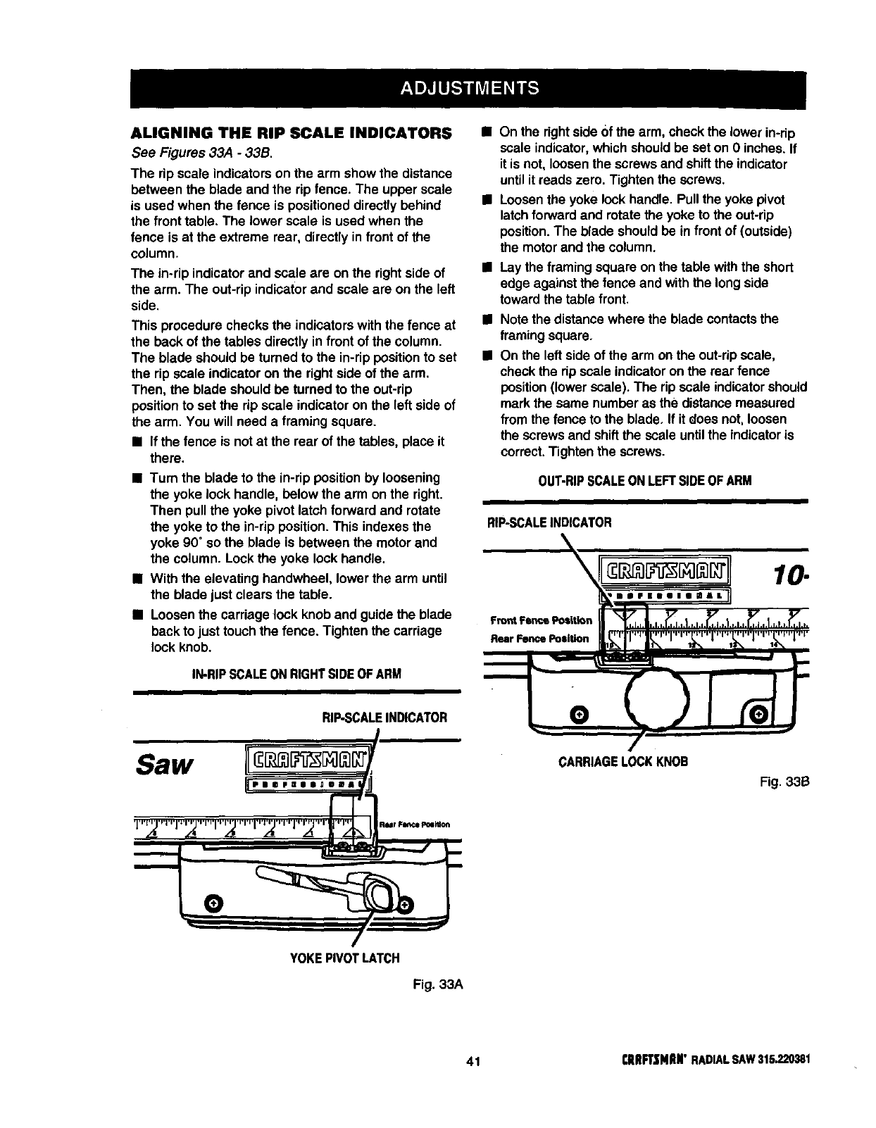
ALIGNING THE RIP SCALE INDICATORS
See Figures 33A -33B.
The rip scale indicatorson the arm show the distance
between the blade and the rip fence. The upper scale
is used when the fence is positioneddirectly behind
the front table. The lower scale is used when the
fence is at the extreme rear, directlyin front of the
column.
The in-rip indicator and scale are on the rightside of
the arm. The out-rip indicator and scale are on the left
side.
This procedure checks the indicators with the fence at
the beck of the tables directly in front of the column.
The blade should be turned to the in-rip positionto set
the rip scale indicatoron the rightside of the arm.
Then, the blade should be turnedto the out-rip
positionto set the rip scale indicator on the left side of
the arm. You will need a framing square.
•If the fence is notat the rear of the tables, place it
there.
•Tum the blade to the in-rip position by loosening
the yoke lock handle, below the arm on the right.
Then pull the yoke pivot latch forward and rotate
the yoke to the in-rip position. This indexes the
yoke 90" so the blade is between the motor and
the column. Lockthe yoke lock handle.
•With the elevating handwheel, lower the arm until
the blade just clears the table.
•Loosenthe carriage lock knob and guide the blade
back to just touch the fence. Tighten the carriage
lock knob,
IN-RIPSCALEONRIGHTSIDEOFARM
RIP-SCALEINDICATOR
Saw
PmoFEOB_DBm_
Vl-,_J,,,l,ITVl-,_j,rri,i-,'f'i_rrl,,T,'l_'rrl ,'I'; Rur FsetcePolsl_i_
L
• On the right side Ofthe arm, check the lower in-rip
scale indicator, which should be set on O inches. If
it is not, loosen the screws and shiftthe indicator
until it reads zero. Tighten the screws.
• Loosen the yoke lock handle. Pull the yoke pivot
latch forward and rotate the yoke to the out-rip
position. The blade should be in front of (outside)
the motor and the column,
•Lay the framingsquare on the table withthe short
edge against the fence and with the long side
toward the table front.
Note the distance where the blade contactsthe
framing square.
On the left side of the arm on the out-ripscale,
check the rip scale indicatoron the rear fence
position(lower scale). The rip scale indicatorshould
mark the same number as the distance measured
fromthe fence to the blade. If it does not, loosen
the screws and shiftthe scale untilthe indicatoris
correct.Tighten the screws.
OUTmRIPSCALEON LEFTSIDEOFARM
RIP-SCALEINDICATOR
CARRIAGELOCKKNOB
Fig. 33B
YOKEPIVOTLATCH
Fig. 33A
41 I:RIIR'SNIIN" RADIALSAW315.220381
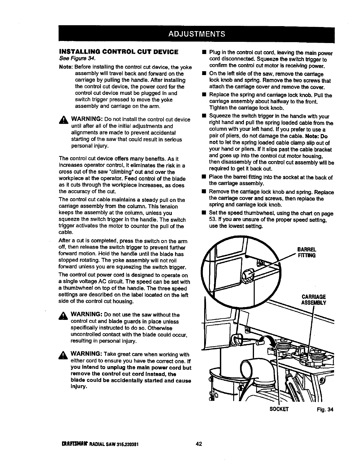
INSTALLING CONTROL CUT DEVICE
See Figure 34.
Note: Before installing the controlcut device, the yoke
assemblywill travelback and forwardon the
carriage by pullingthe handle. After installing
the controlcut device, the power cordfor the
controlcut device must be pluggedinand
switchtriggerpressed to move the yoke
assemblyand carriage on the arm.
WARNING: Do not install the control cut device
until after all of the initial adjustments and
alignments are made to prevent accidental
starting of the saw that could result in serious
personal injury.
The control cut device offersmany benefits.As it
Increases operator control,It eliminatesthe riskin a
crosscut of the saw "climbing"out and over the
workplaceat the operator. Feed control of the blade
as it cuts throughthe workpiece increases,as does
the accuracyof the cut.
The control cutcable maintainsa steady pullon the
carriage assemblyfrom the column.This tension
keeps the assemblyat the column,unlessyou
squeeze the switchtrigger in the hendte.The switch
triggeractivatesthe motor to counterthe pullof the
cable.
Aftera cut is completed, pressthe switchon the arm
off, then release the switchtriggerto preventfurther
forwardmotion.Hold the handleuntilthe blade has
stoppedrotating.The yoke assemblywill notroll
forward unlessyou are squeezingthe switchtrigger.
The control cut power cord is designedto operate on
a singlevoltageAC circuit.The speed can be set with
a thumbwheelon top of the handle. The three speed
settingsare describedon the label locatedon the left
side of the control cut housing.
_k WARNING: Do not use the saw withoutthe
controlcut and blade guardsin place unless
specifically Instructed to do so. Otherwise
uncontrolled contact with the blade could occur,
resulting in personal injury.
_1= WARNING: Take great care when working with
either cord to ensure you have the correct one. If
you Intend to unplug the main power cord but
remove the control cut cord Instead, the
blade could be accidentally started and cause
Injury.
•Plug inthe controlcut cord,leavingthe mainpower
cord disconnected.Squeeze the switchtriggerto
confirm the control cut motoris receivingpower.
• On the left side of the saw, remove the carriage
lock knob and spdng. Remove the two screws that
attach the carriage cover and remove the cover.
•Replace the spring and cardage lock knob. Pull the
carriage assembly about halfway to the front.
Tighten the carriage lock knob.
•Squeeze the switch trigger in the handle with your
right hand and pull the spring loaded cable from the
column with your left hand. If you prefer to use a
pair of pliers, do not damage the cable. Note: Do
not to let the spring loaded cable clamp slip out of
your hand or pliers. If it slips past the cable bracket
and goes up Into the control cut motor housthg,
then disassembly of the control cut assembly will be
required to get it back out.
•Place the barrel fitting into the socket at the back of
the carriage assembly.
•Remove the carriage lock knob and spring. Replace
the carriage cover and screws, then replace the
spring and carriage lock knob.
•Set the speed thumbwhee], using the chart on page
53. If you are unsure of the proper speed setting,
use the lowest setting.
BARREL
CARRIAGE
ASSEMBLY
SOCKET F_.34
[ItlIFTSNAItRADIAL SAW 315.?.20381 42
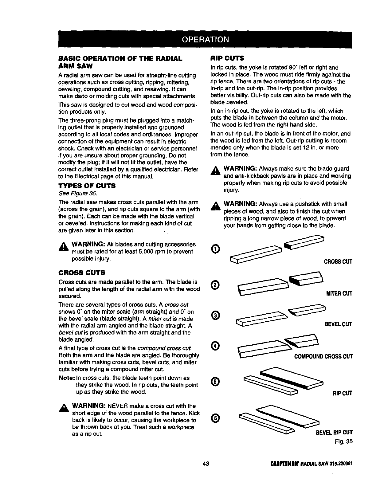
BASIC OPERATION OF THE RADIAL
ARM SAW
A radial arm saw can be used for straight-linecutting
operations such as cross cutting,ripping,mitering,
beveling, compoundcutting, and resawing. It can
make dado or moldingcuts with special attachments.
This saw is designed to cut wood and wood composi-
tion products only.
The three-prong plugmust be plugged into a match-
ing outlet that is properlyinstalled and grounded
accordingto all local codes and ordinances. Improper
connection of the equipment can result in electric
shook. Check withan electrician or service personnel
if you are unsure about proper grounding. Do not
modify the plug;if it will not fit the outlet, have the
correct outlet installed by a qualifiedelectrician. Refer
to the Electricalpage of this manual.
TYPES OF CUTS
See Figure 35.
The radial saw makes cross cuts parallel withthe arm
(across the grain), and rip cuts square to the arm (with
the grain). Each can be made withthe blade vertical
or beveled, instructionsfor making each kind of cut
are given later inthis section.
_lb WARNING: All blades and cuttingaccessories
must be rated for at least 5,000 rpm to prevent
possible injury.
CROSS CUTS
Cross cuts are made parallel to the arm. The blade is
pulled along the length of the radial arm withthe wood
secured.
There are several typos of cross cuts. A crossout
shows O"on the miter scale (arm straight) and O"on
the bevel scale (blade straight). A mitercutis made
withthe radial arm angled and the blade straight. A
bevel cut is produced withthe arm straightand the
blade angled.
Afinal type of cross cut is the compound cross cut,
Both the arm and the blade are angled. Be thoroughly
familiar with making cross cuts, bevel cuts, and miter
cuts before trying a compound miter cut.
Note: In crosscuts, the blade teeth point down as
they strikethe wood. In rip cuts, the teeth point
up as they strikethe wood.
_&, WARNING: NEVER make a cross cut with the
short edge of the wood parallel to the fence. Kick
back is likely to occur,causing the workpieca to
be thrownback at you. Treat sucha workpiece
as a rip cut.
RIP CUTS
In rip cuts, the yoke is rotated 90" left or rightand
locked in place. The wood must ride firmly against the
rip fence. There are two orientationsof rip cuts - the
in-ripand the out-rip.The in-rip positionprovides
better visibility.Out-rip cuts can also be made with the
blade beveled,
In an in-rip cut, the yoke is rotated to the left, which
putsthe blade in between the column and the motor.
The wood is fed from the righthand side.
In an out-rip cut, the blade is in front of the motor,and
the wood is fed from the left. Out-rip cuttingis recom-
mended only when the blade is set 12 in. or more
from the fence.
,_. WARNING: Always make sure the blade guard
and anti-kickbackpawls are in place and working
properlywhen making rip cuts to avoid possible
injury.
_lb WARNING: Always use a pushstickwithsmall
pieces of wood, and also to finishthe cut when
rippinga long narrow piece of wood, to prevent
your hands from getting close to the blade.
CROSSCUT
Q _'__BEVEL CUT
COMPOUNDCROSSCUT
Q __ RiPCUT
@s v,,R,PCuT
Fig. 35
43 DIAFTSMIIIFRADIALSAW315.220381
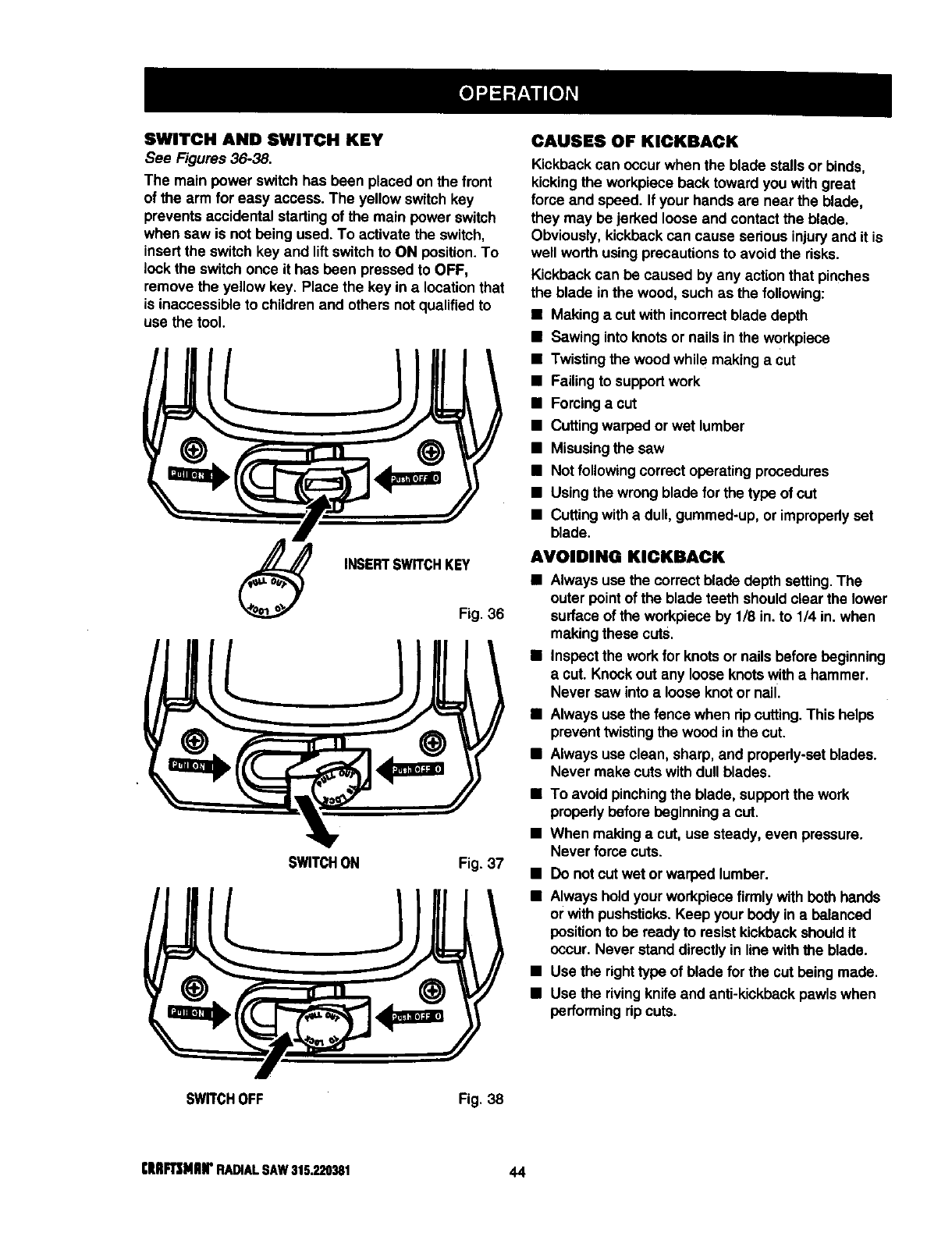
SWITCH AND SWITCH KEY
See Figures 36-38.
The main power switch has been placed on the front
of the arm for easy access. The yellow switch key
prevents accidental startingof the main power switch
when saw is not being used. To activate the switch,
insert the switch key and lift switchto ON position. To
lockthe switchonce it has been pressed to OFF,
remove the yellow key. Place the key in a location that
is inaccessible to children and others not qualifiedto
use the tool.
INSERTSWITCHKEY
Fig. 36
SWITCHON Fig. 37
CAUSES OF KICKBACK
Kickback can occur when the blade stalls or binds,
kickingthe workpiece back toward you with great
force and speed. If your hands are near the blade,
they may be jerked loose and contactthe blade.
Obviously, kickbackcan cause serious injuryand it is
well worth using precautionsto avoid the dsks.
Kickback can be caused by any action that pinches
the blade in the wood, suchas the following:
•Making a cut with incorrectblade depth
•Sawing into knotsor nails in the workpiece
•Twistingthe wood while making a cut
•Failingto supportwork
•Forcinga cut
•Cuttingwarped or wet lumber
•Misusingthe saw
•Not followingcorrectoperating procedures
•Usingthe wrong blade forthe type of cut
•Cuttingwith a dull, gummed-up, or impropedyset
blade.
AVOIDING KICKBACK
•Always use the correct blade depth setting.The
outer point of the blade teeth shouldclear the lower
surface of the workpiece by 1/8 in. to 1/4 in. when
makingthese cuts.
•Inspectthe work for knotsor nails before beginning
acut. Knockout any loose knotswith a hammer.
Never saw into a loose knotor nail
•Always use the fence when dp cutting.This helps
prevent twistingthe wood in the cut.
•Always use clean, sharp, and properly-setblades.
Never make cuts with dullblades.
•To avoid pinchingthe blade, supportthe work
propedy before beginning a cut.
•When making a cut, use steady, even pressure,
Never force cuts.
•Do not cut wet or warped lumber.
•Always holdyour workpiece firmlywith beth hands
or with pushsticks.Keep your body in a balanced
position to be ready to resist kickbackshouldit
occur. Never stand directly in line withthe blade.
•Use the righttype of blade for the cut being made.
•Use the rivingknifeand anti-kickbackpawlswhen
performing ripcuts.
SWITCHOFF Fig. 38
rlIIIF_NIIN* RADIALSAW315.220381 44
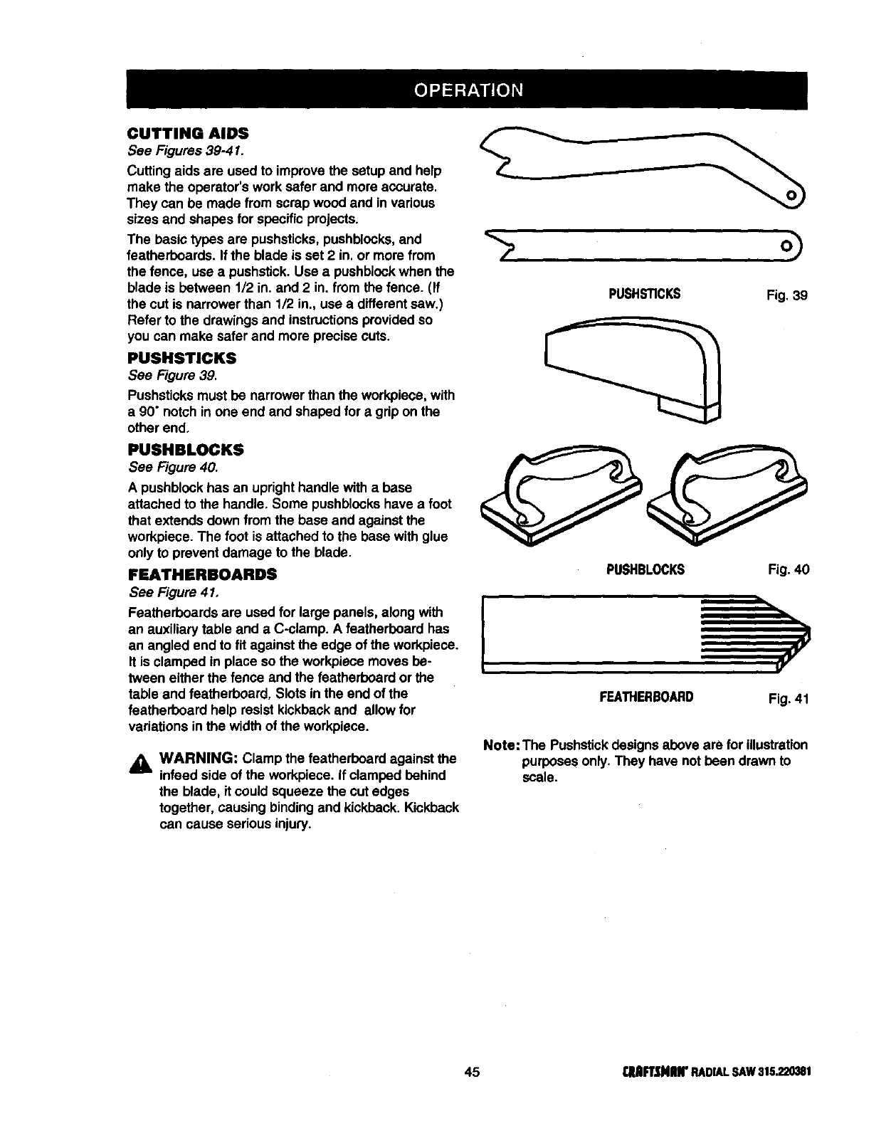
CUTTING AIDS
See Figures 39-41.
Cutting aids are used to improvethe setup and help
make the operator's work safer and more accurate.
They can be made from scrapwood and in various
sizes and shapes for specific projects.
The basictypos are pushsticks, pushblccks,and
featherboards. If the blade is set 2 in. or more from
the fence, use a pushstick. Use a pushblcck when the
blade is between 1/2 in. and 2 in. from the fence. (If
the cut is narrower than 1/2 in., use a differentsaw.)
Refer to the drawings and instructionsprovidedso
you can make safer and more precise cuts.
PUSHSTICKS
See Figure 39.
Pushsticksmust be narrower than the workpiece, with
a 90" notch in one end and shaped for a grip on the
other end.
PUSHBLOCKS
See Figure 40.
A pushblockhas an uprighthandle with a base
attached to the handle. Some pushblockshave a foot
that extends down fromthe base and against the
workpiece. The foot is attached to the base with glue
only to prevent damage to the blade.
FEATNERBOARDS
See Figure 41,
Featherboards are used for large panels, along with
an auxiliary table and a C-clamp. A featherboard has
an angled end to fit against the edge of the workpiece.
It is clamped in place so the workpiece moves be-
tween either the fence and the featherboard or the
table and featherboard, Slots in the end of the
featherboard help resist kickbackand allow for
variations inthe width of the workpiece.
_i WARNING: Clamp the featherboard against the
infeed side of the workpiece. If clamped behind
the blade, it could squeeze the cut edges
together, causing binding and kickback. Kickback
can cause serious injury.
--> o)
PUSHSTICKS Fig. 39
OO
PUSHBLOCKS Fig. 40
2
FEATHERBOARD Fig. 41
Note: The Pushstickdesigns above are for illustration
purposes only. They have not been drawn to
scale.
45 r.lllFUNIIIrRADIALSAW315.220381
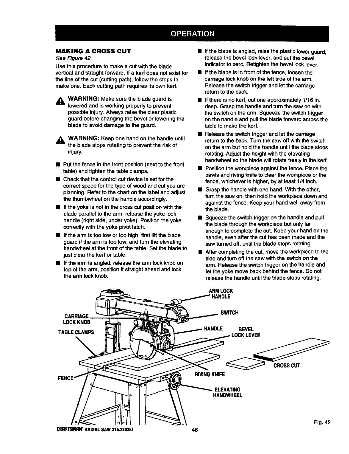
MAKING A CROSS CUT
See Figure 42.
Use this procedureto make a cut with the blade
vertical and straightforward. If a kerrdoes not exist for
the line of the cut (cutting path), followthe steps to
make one. Each cutting path requires its own kerr.
_k WARNING: Make sure the blade guard is
lowered and is working properly to prevent
possible injury.Always raise the clear plastic
guard before changingthe bevel or loweringthe
blade to avoid damage to the guard.
_k WARNING: Keep one hand on the handle until
the blade stops rotating to prevent the risk of
injury.
•Put the fence in the front position(next to the front
table) and tightenthe table clamps.
•Check that the control cut device is set for the
correct speed for the type of wood and cut you are
planning. Refer to the chart on the label and adjust
the thumbwheel on the handle accordingly.
•If the yoke is not inthe crosscut positionwiththe
blade parallel to the arm, release the yoke lock
handle (rightside, under yoke). Positionthe yoke
correctlywith the yoke pivot latch.
•If the arm is too low or too high, firstlift the blade
guard if the arm is too low, and turn the elevating
handwheel at the front of the table. Set the blade to
just clear the kerror table.
•If the arm is angled, release the arm lockknob on
top of the arm, positionit straightahead and lock
the arm lock knob.
•If the blade is angled, raise the plasticlower guard,
release the bevel lock lever, and set the bevel
indicatorto zero. RaUghtenthe bevel lock lever.
•If the blade is in front of the fence, loosenthe
carriage lock knob on the left side of the arm.
Release the switchtrigger and let the carriage
returnto the back.
If there is no kerf, cut one approximately1/16 in.
deep. Grasp the handle and turn the saw on with
the switchon the arm. Squeeze the switchtrigger
onthe handleand pullthe blade forwardacrossthe
table to make the kerf.
•Release the switchtrigger and let the carriage
returnto the back. Turn the saw off with the switch
on the arm but holdthe handle untilthe blade stops
rotating.Adjustthe height withthe elevating
handwheel so the blade will rotatefreely in the kerr.
•Positionthe workpieceagainst the fence. Place the
pawlsand riving knifeto clearthe workpieceorthe
fence, whicheveris higher, by at least 1/4 inch.
•Grasp the handlewith one hand. With the other,
turn the saw on, then holdthe workpiecedown and
against the fence. Keep your hand well away from
the blade.
•Squeeze the switchtrigger on the handle and pull
the blade throughthe workplace but only far
enough to complete the cut. Keep your hand on the
handle, even after the cut has been made and the
saw turnedoff, untilthe blade stops rotating.
•Aftercompletingthe cut, move the workpieceto the
side and turn off the saw with the switchon the
arm. Release the switchtrigger on the handle and
let the yoke move back behind the fence. Do not
releasethe handle untilthe blade stops rotating.
ARMLOCK
CARNAGE
LOCKKNOB
TABLECLAMPS
SWITCH
HANDLE
RIVINGKNIFE
BEVEL
CROSSCUT
ELEVATING
HANDWHEEL
Fig. 42
€IIRFt'J;MIIIrRADIALSAW315.220381 46
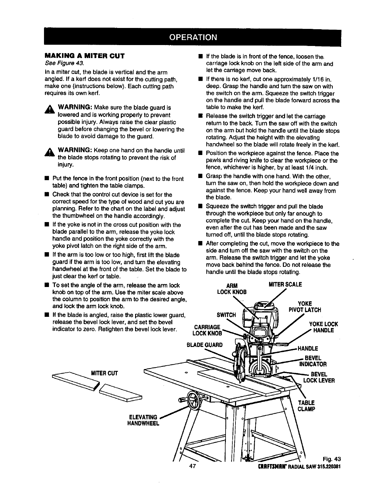
MAKING A MITER CUT
See Figure 43.
In a miter cut, the blade is vertical and the arm
angled. If a kerf does not exist for the cuttingpath,
make one (instructionsbelow). Each cutting path
requires its own kerr.
_, WARNING: Make sure the blade guard is
lowered and is working propedy to prevent
possible injury.Always raise the clear plastic
guard before changingthe bevel or loweringthe
blade to avoid damage to the guard.
,_ WARNING: Keep one hand on the handle until
the blade stops rotatingto prevent the risk of
injury.
•Put the fence inthe front position(next to the front
table) and tighten the table clamps.
•Check that the controlcut device is set for the
correct speed for the type of wood and cut you are
planning. Refer to the chart on the label and adjust
the thumbwheel on the handle accordingly.
•If the yoke is not in the cross cut position withthe
blade parallel to the arm, release the yoke lock
handle and position the yoke correctlywith the
yoke pivotlatch on the rightside of the arm.
•If the arm is too low or too high, first lift the blade
guard if the arm is too low, and turn the elevating
handwheel at the front of the table. Set the blade to
just clear the kerr or table.
•To set the angle of the arm, release the arm lock
knob on top of the arm. Use the miter scale above
the column to position the arm to the desiredangle,
and lock the arm lock knob.
•If the blade is angled, raise the plastic lower guard,
release the bevel lock lever, and set the bevel
indicatorto zero. Retighten the bevel locklever.
ERCUT
ELEVATING
HANDWHEEL
If the blade is infront of the fence, loosenthe.
carriage lock knob on the left side of the arm and
let the carriage move back.
If there is no kerf, cut one approximately 1/16 in.
deep. Grasp the handle and turn the saw on with
the switch on the arm. Squeeze the switchtrigger
on the handle and pull the blade forward across the
table to make the kerr.
• Release the switchtrigger and let the carriage
return to the back. Turn the saw off withthe switch
on the arm but hold the handle until the blade stops
rotating. Adjust the height with the elevating
handwheel so the blade will rotate freely in the kerf.
• Position the workpiece against the fence. Place the
bawls and riving knife to clear the workpiece or the
fence, whichever is higher, by at least 1/4 inch.
• Grasp the handle with one hand. With the ether,
turn the saw on, then hold the workpiece down and
against the fence. Keep your hand well away from
the blade.
• Squeeze the switchtrigger and pull the blade
throughthe workpiece but only far enough to
complete the cut.Keep your hand on the handle,
even after the cut has been made and the sew
turnedoff, untilthe blade stops rotating.
•Aftercompletingthe cut, move the workpieceto the
side and turn oft the saw withthe switchon the
arm. Release the switchtrigger and let the yoke
move back behind the fence. Do not release the
handleuntilthe blade stopsrotating.
ARM MITERSCALE
LOCKKNOB
SWITCH
YOKE
PIVOTLATCH
YOKELOCK
BLADEGUARD
BEVEL
INDICATOR
BEVEL
LOCKLEVER
TABLE
CLAMP
Fig. 43
47 [RIIFTSNlUr RADIALSAW315.220381
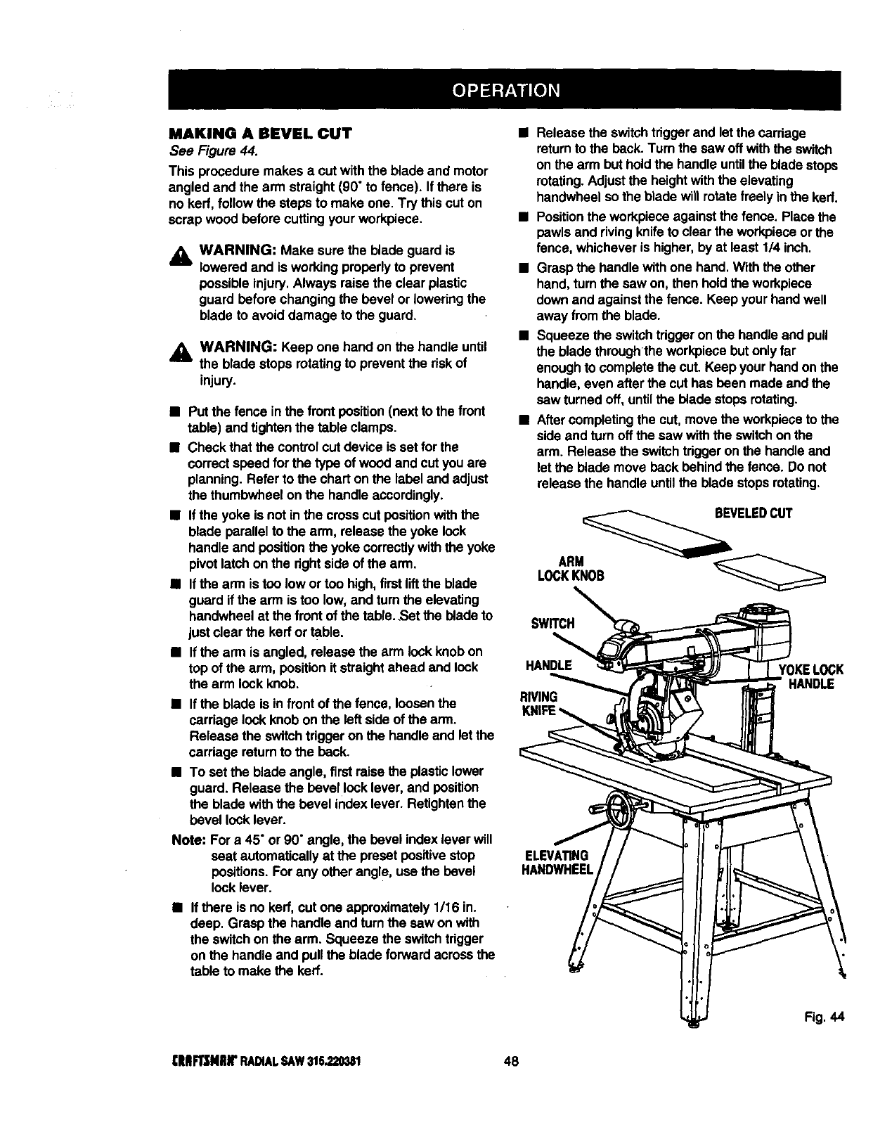
MAKING A BEVEL CUT
See Figure 44.
This procedure makes a cut with the blade and motor
angled and the arm straight (90" to fence). If there is
no ked, follow the steps to make one. Try thiscut on
scrap wood before cutting your workpiece.
_k WARNING: Make sure the blade guard is
lowered and is working properlyto prevent
possible injury.Always raise the clear plastic
guard before changingthe bevel or loweringthe
blade to avoid damage to the guard.
_l, WARNING: Keep one hand on the handle until
the blade stops rotating to prevent the risk of
injury.
•Put the fence in the front position(next to the front
table) and tightenthe table clamps.
•Check that the controlcut device is set for the
correct speed forthe type of wood and cut you are
planning. Refer to the chart on the label and adjust
the thumbwheel on the handle accordingly.
•If the yoke is not in the crosscut position withthe
blade parallel to the arm, release the yoke lock
handle and position the yoke correctlywiththe yoke
pivot latch onthe rightside of the arm.
•If the arm is too low or too high, first liftthe blade
guard if the arm is too low, and turn the elevating
handwheel at the front of the table..Set the blade to
just clear the kerror table.
•If the arm is angled, release the arm lock knob on
top of the arm, position it straightahead and lock
the arm lock knob.
•If the blade is in front of the fence, loosenthe
carriage lockknob on the left side of the arm.
Release the switchtrigger on the handle and let the
carriage returnto the beck.
•To set the blade angle, first raise the plastic lower
guard. Release the bevel locklever, and position
the blade with the bevel index lever. Retighten the
bevel lock lever.
Note: For a 45" or 90" angle, the bevel index lever will
seat automaticallyat the preset positive stop
positions. For any other angle, use the bevel
lock lever.
•If there is no kerf, cut one approximately 1/16 in.
deep. Grasp the handle and turn the sew on with
the switchon the arm. Squeeze the switchtrigger
on the handle and pull the blade forward across the
table to make the kerr.
•Release the switchtriggerand let the carriage
returnto the back. Turn the saw off with the switch
on the arm but holdthe handle untilthe blade stops
rotating.Adjust the heightwith the elevating
handwheel so the blade will rotatefreely inthe ked.
•Positionthe workpieceagainst the fence. Place the
pawls and rivingknifeto clear the workpieceorthe
fence, whichever is higher,by at least 1/4 inch.
•Grasp the handlewith one hand. With the other
hand, turn the saw on, then holdthe workpiece
down and against the fence. Keep your hand well
away from the blade.
•Squeeze the switchtriggeron the handleand pull
the blade throughthe workpiece butonly far
enough to complete the cut. Keep your hand on the
handle, even after the cut has been made and the
saw turnedoff, untilthe blade stopsrotating.
•After completingthe cut, move the workpieceto the
side and turn off the saw with the switchon the
arm. Release the switchtrigger on the handleand
let the blade move beck behind the fence. Do not
release the handle untilthe blade stopsrotating.
EVELEDCUT
SWITCH
HANDLE
RIVING
YOKELOCK
HANDLE
ELEVATING
HANDWHEEL
[IIIFI"SNIIN" RADIALSAW315.220381 48
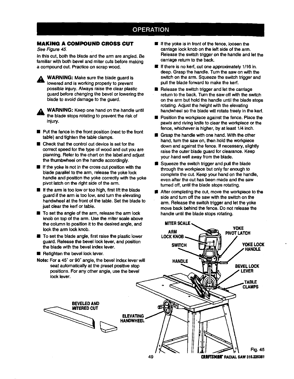
MAKING A COMPOUND CROSS CUT
See Figure 45.
In thiscut, both the blade and the arm are angled. Be
familiar with both bevel and miter cuts before making
a compound cut. Practice on scrap wood.
_l, WARNING: Make sure the blade guard is
lowered and is working properlyto prevent
possible injury.Always raise the clear plastic
guard before changing the bevel or loweringthe
blade to avoid damage to the guard.
_l, WARNING: Keep one hand onthe handle until
the blade stops rotatingto prevent the riskof
injury.
•Put the fence in the front position (next to the front
table) and tightenthe table clamps.
•Check that the controlcut device is set for the
correct speed for the type of wood and cut you are
planning. Refer to the chart on the label and adjust
the thumbwheel on the handle accordingly.
•If the yoke is not in the crosscut position withthe
blade parallel to the arm, release the yoke lock
handle and position the yoke correctlywith the yoke
pivot latchon the rightside of the arm.
•If the arm is too low or too high,first liftthe blade
guard if the arm is too low, and turnthe elevating
handwheel at the front of the table. Set the blade to
just clear the kerror table.
•To sat the angle of the arm, release the arm lock
knob on topof the arm. Use the miter scale above
the columnto position itto the desired angle, and
lock the arm look knob.
•To set the blade angle, firstraise the plasticlower
guard. Release the bevel lock lever, and position
the blade withthe bevel index lever.
•Retighten the bevel lock lever.
Note: For a 45" or 90" angle, the bevel index leverwill
seat automatically at the preset positive stop
positions. For any other angle, use the bevel
lock lever.
•If the yoke is infront of the fence, loosen the
carriage lockknob on the left side of the arm.
Release the switchtrigger onthe handle and let the
carriage returnto the back.
•If there is no kerr, cut one approximately 1/t6 in.
deep. Grasp the handle. Turn the saw on withthe
switchon the arm. Squeeze the switchtrigger and
pullthe blade forwardto make the kerf.
•Release the switchtdggerand let the carriage
returnto the beck. Turn the saw off withthe switch
on the arm but holdthe handle untilthe blade stops
rotating.Adjustthe heightwiththe elevating
handwheel so the blade will rotatefreely inthe kerr.
•Positionthe workpieceagainst the fence. Place the
pawlsand rivingknife to clear the workpiece or the
fence, whichever is higher, by at least 1/4 inch.
•Grasp the handle With one hand. With the other
hand, turn the saw on, then holdthe workplece
down and against the fence• If necessary, slightly
raise the outer blade guardfor clearance. Keep
your hand well away from the blade.
•Squeeze the switchtriggerand pullthe blade
throughthe workpiece but onlyfar enough to
complete the cut. Keep your hand on the handle,
even after the cut has been made and the saw
turned off, untilthe blade stopsrotating.
•Aftercompletingthe cut, move the workpieceto the
side and turn off the saw withthe switchon the
arm. Release the switchtriggerand let the yoke
move back behind the fence. Do not release the
handle untilthe blade stopsrotating.
ARM
SWWCH
YOKE
PIVOTLATCH
YOKELOCK
HANDLE BEVELLOCK
LEVER
¸TABLE
BEVELEDAND
ELEVATING
HANDWHEEL
Fig. 45
49 (lUIIFTSMEI("RADIALSAW315.220381
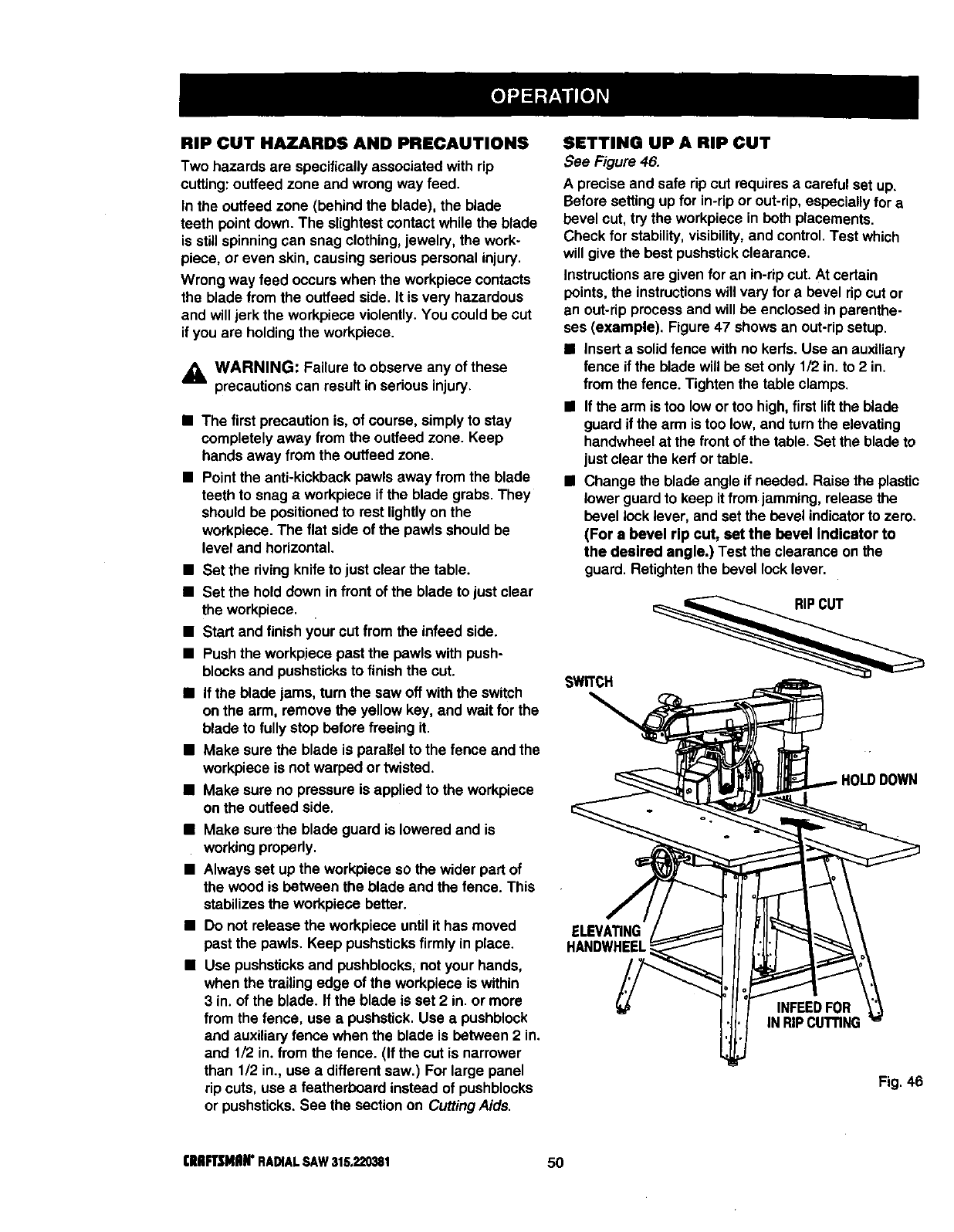
RIP CUT HAZARDS AND PRECAUTIONS
Two hazards are specificallyassociated with rip
cutting:outfeed zone and wrong way feed,
In the ouffeed zone (behind the blade), the blade
teeth pointdown. The slightestcontact while the blade
is stillspinning can snag clothing, jewelry, the work-
piece, or even skin, causing seriouspersonal injury.
Wrong way feed occurs when the workpiececontacts
the blade from the ouffeed side. It is very hazardous
and willjerk the workpiece violently.You could be cut
if you are holding the workpiece.
,_k WARNING: Failure to observe any of these
precautionscan result in serious injury.
•The first precaution is, of course, simply to stay
completely away from the ouffeed zone. Keep
hands away from the outfeed zone.
•Point the anti-kickback pawls away from the blade
teeth to snag aworkpiece if the blade grabs. They
should be positionedto rest lightlyon the
workpiece. The flat side of the pawls should be
level and horizontal.
•Set the riving knifeto just clear the table.
•Set the hold down in front of the blade to just clear
the workpiece.
• Start and finish your cut from the infeed side.
•Push the workpiece past the pawls with push-
blocksand pushsticksto finish the cut.
•If the blade jams, turn the saw off with the switch
on the arm, remove the yellow key, and wait for the
blade to fullystop before freeing it.
•Make sure the blade is parallel to the fence and the
workpiece is not warped or twisted.
•Make sure no pressure is applied to the workpiece
on the ouffeed side.
•Make sure the blade guard is lowered and is
working properly.
•Always set up the workpiece so the wider part of
the wood is between the blade and the fence. This
stabilizes the workpiece better.
•Do not release the workpiece until it has moved
past the pawls. Keep pushsticksfirmly in place.
•Use pushsUcksand pushblocks, not your hands,
when the trailing edge of the workpiece is within
3 in. of the blade. If the blade is set 2 in. or more
from the fence, use apushstiok.Use a pushblock
and auxiliary fence when the blade is between 2 in.
and 1/2 in. from the fence. (If the cut is narrower
than 1/2 in., use a different saw.) For large panel
rip cuts, use a featherboard instead of pushblocks
or pushsticks.See the section on CuttingAids.
SETTING UP A RIP CUT
See Figure 46.
A precise and safe rip cut requires acareful set up.
Before setting up for in-rip or out-rip, especiallyfor a
bevel cut, try the workpiece in both placements.
Check for stability, visibility,and control.Test which
will give the best pushstickclearance.
Instructionsare given for an in-ripcut. At certain
points,the instructionswill vary for a bevel rip cut or
an out-rip process and will be enclosed in parenthe-
ses (example), Figure 47 shows an out-ripsetup.
•Insert a solidfence withno kerfs. Use an auxiliary
fence if the blade will be set only 1/2 in. to 2 in.
from the fence. Tighten the table clamps,
•If the arm is too lowor too high, firstliftthe blade
guard if the arm is too low, and turn the elevating
handwheel at the front of the table. Set the blade to
justclear the kerf or table.
•Change the blade angle if needed. Raise the plastic
lower guard to keep it fromjamming, release the
bevel lock lever, and set the bevel indicatorto zero.
(For a bevel rip cut, set the bevel Indicator to
the desired angle.) Test the clearance on the
guard. Retighten the bevel lock lever.
ELEVATING
HANDWHEEL
INFEEDFOR
IN RIPCUTTING
Fig. 46
I'IIIIFTSMIIIP RADIALSAW315.220381 50
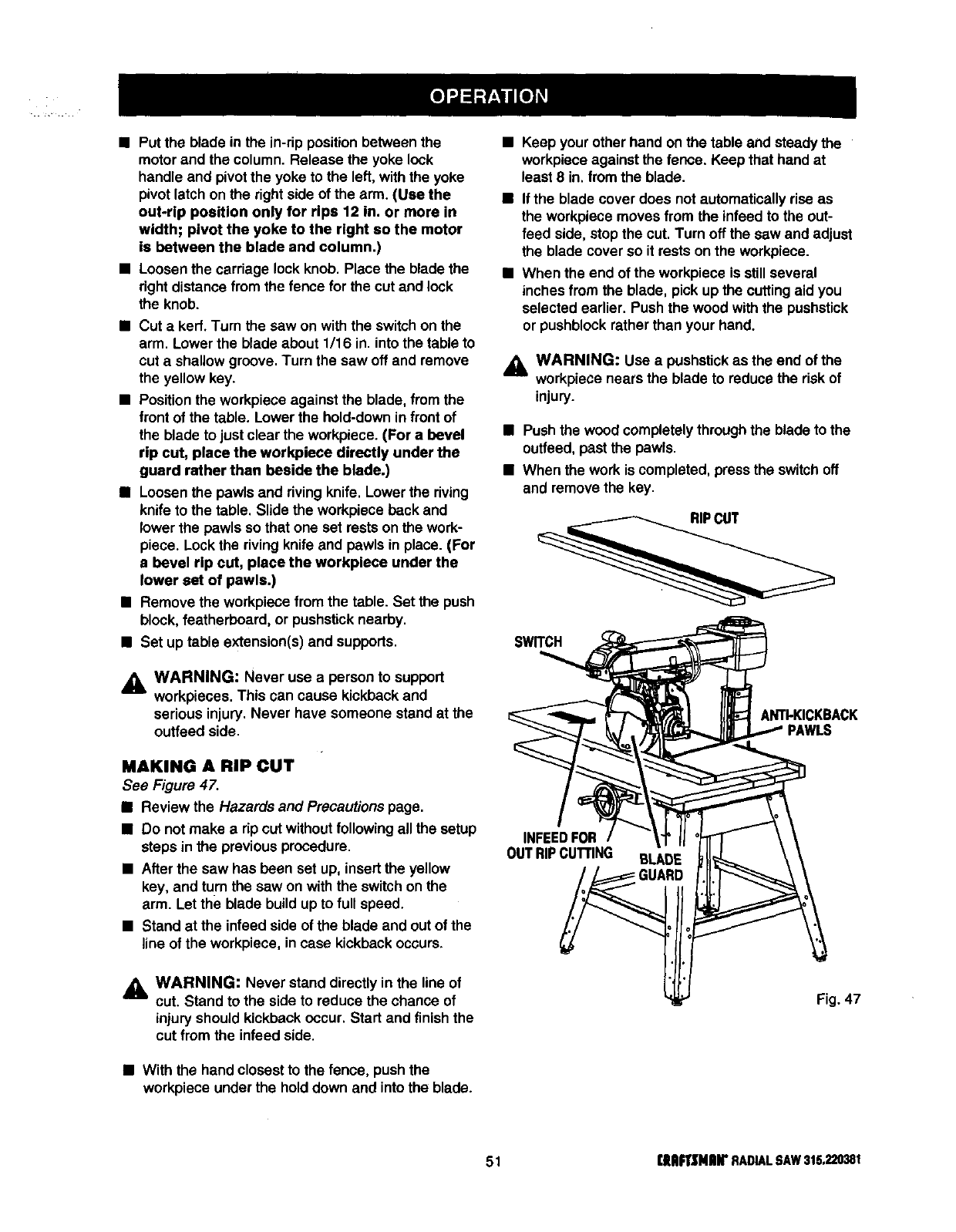
•Put the blade in the in-rip positionbetween the
motor and the column. Release the yoke lock
handle and pivotthe yoke to the left,with the yoke
pivot latchon the rightside of the arm. (Use the
out-rip position only for rips 12 in. or more in
width; pivot the yoke to the right so the motor
is between the blade and column.)
•Loosenthe carriage lock knob. Place the blade the
rightdistance from the fence for the cut and lock
the knob.
• Cut akerr. Turn the saw on withthe switchon the
arm. Lower the blade about 1/16 in. into the table to
cut a shallow groove. Turn the saw off and remove
the yellow key.
• Position the workpiece against the blade, from the
front of the table. Lower the hold-down in front of
the blade to just clear the workpiece. (For a bevel
rip cut, place the workpiece directly under the
guard rather than beside the blade.)
•Loosen the pawls and rivingknife. Lower the riving
knife to the table. Slide the workpiece back and
lower the pawls so that one set rests on the work-
piece. Lockthe rivingknife and pawls inplace. (For
abevel rip cut, place the workpiece under the
lower set of pawls.)
•Remove the workpiecefrom the table. Set the push
block,featherboard, or pushsticknearby.
• Set up table extension(s)and supports.
WARNING: Never use a person to support
mworkpieces. This can cause kickback and
serious injury.Never have someone stand at the
ouffeed side.
MAKING A RIP CUT
See Figure 47.
•Review the Hazards and Precautions page.
•Do not make a dp cut without following all the setup
steps in the previous procedure.
• After the saw has been set up, insert the yellow
key, and turn the saw on with the switchon the
arm. Let the blade build up to full speed.
• Stand at the infeed side of the blade and out of the
line of the workpiece, in case kickback occurs.
_. WARNING: Never stand directly in the line of
cut. Stand to the side to reduce the chance of
injury should kickback occur. Start and finish the
cut from the infeed side.
• With the hand closestto the fence, push the
workpiece under the hold down and into the blade.
Keep your other hand onthe table and steady the
workpieceagainst the fence. Keep that hand at
least 8 in. from the blade.
If the blade cover does notautomatically riseas
the workpiecemoves from the infeed to the out-
feed side, stop the cut. Turn off the saw and adjust
the blade cover so it rests on the workpiece.
When the end of the workpiece is still several
inches from the blade, pick up the cuttingaid you
selected earlier. Push the wood with the pushstick
or pushblockrather than your hand.
,_ WARNING: Use a pushstickas the end of the
workpiece nears the blade to reduce the risk of
injury.
•Pushthe wood completelythroughthe blade to the
outfeed,past the pawls.
•When the work is completed, pressthe switchoff
and remove the key.
SWITCH
ANTI-KICKBACK
INFEED FOR
OUT RIP CUTTING BLADE
Fig. 47
51 rllAFrSMlUr RADIALSAW315,220381
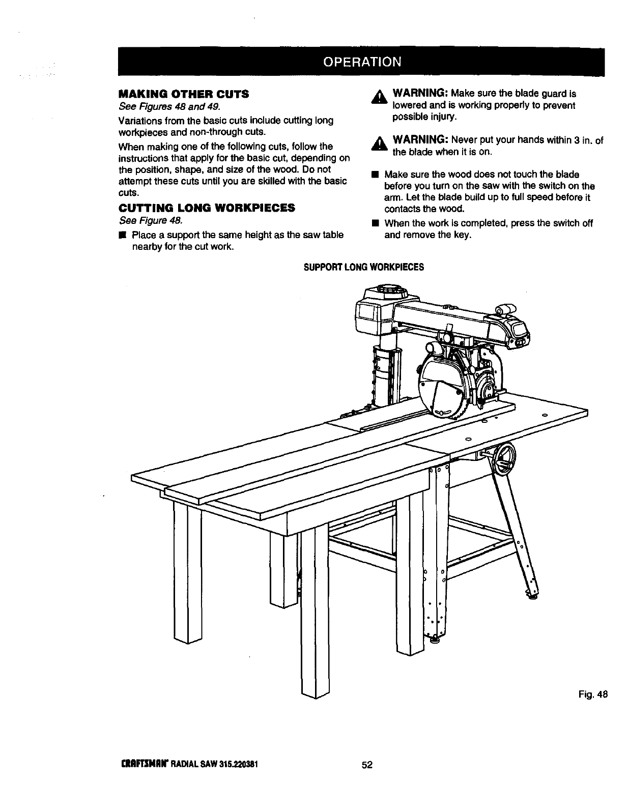
MAKING OTHER CUTS
See Figures 48 and 49.
Variations fromthe basic cuts include cuttinglong
workpieces and non-through cuts.
When making one of the followingcuts, followthe
instructionsthat apply for the basiccut, depending on
the position,shape, and size of the wood. Do not
attempt these cuts untilyou are skilledwith the basic
cuts.
CUTTING LONG WORKPIECES
See Figure 48.
•Place a supportthe same heightas the saw table
nearby for the cut work.
WARNING: Make sure the blade guard is
loweredand is working properlyto prevent
possible injury.
_, WARNING: Never put your hands within 3 in. of
the blade when it is on.
• Make sure the wood does nottouch the blade
before you turn on the saw with the switchon the
arm. Let the blade build up to full speed before it
contactsthe wood.
•When the work is completed, pressthe switchoff
and remove the key.
SUPPORTLONGWORKPIECES
I
I
I
Fig.48
rMFl_Mnr RADIALSAW316.220381 52
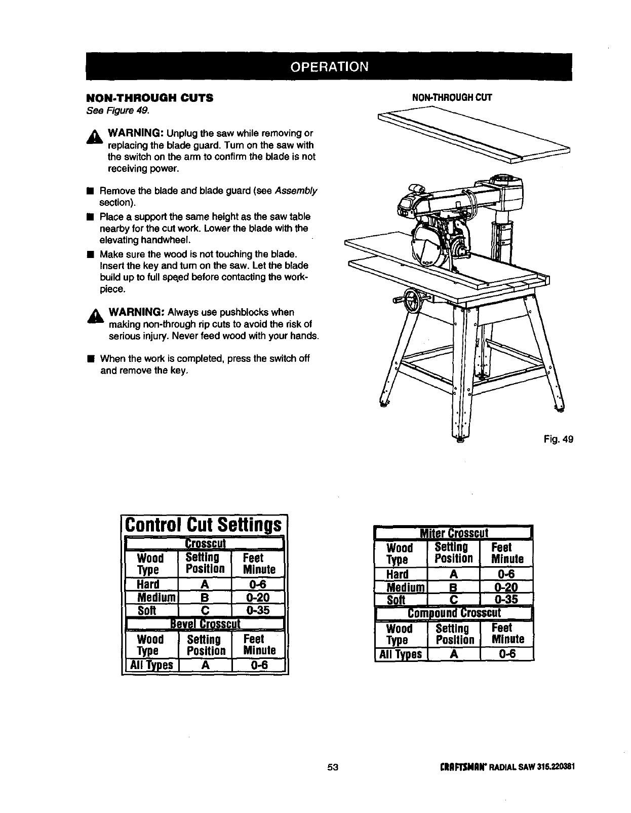
NON-THROUGH CUTS
See Figure 49.
,_ WARNING: Unplug the saw while removing or
replacing the blade guard. Turn on the saw with
the switch on the arm to confirmthe blade is not
receiving power.
•Remove the blade and blade guard (see Assembly
section).
•Place a support the same heightas the saw table
nearby for the cut work. Lower the blade withthe
elevating handwheel.
•Make sure the wood is nottouchingthe blade.
Insertthe key and turn on the sew. Let the blade
buildup to full speed before contactingthe work-
piece,
WARNING: Always use pushblockswhen
making non-through rip cuts to avoid the riskof
serious injury.Never feed wood withyour hands.
•When the work is completed, press the switchoff
and remove the key,
NON-THROUGHCUT
Fig. 49
Control Settings
Crosscut
Wood ISetling IFeet
Type Position Minute
Hard A
Medium B 0-0260
Sott C 0-35
B=vel Crossc Jt
Wood Setting Feet
Type Position Minute
All Types A 0-6
53 rllllPTSNRIr RADIALSAW315,_)0381
GENERAL MAINTENANCE
,_ WARNING: When servicing,use only identical
Craftsman replacement parts. Use of any other
part may create a hazard or cause product
damage.
,_ WARNING: To prevent accidental startingthat
could cause possible serious personal injury,turn
off the saw with the switchon the arm, remove
the switch key, and unplugthe saw before
working on the radial saw.
•Remove sawdust from the work area, including
inside the blade cover, frequently.
•Remove sawdust from and clean the blade guards
frequently.
•Clean plastic parts with a soft damp cloth. Do not
use any strongsolvents.
_k WARNING: Do notat any time let brake fluids,
gasoline, petroleum-based products,penetrating
oils, etc. contact plastic parts. They contain
chemicals that can damage, weaken or destroy
plastic.
• Check teeth of anti-kickback pawls; sharpen with
file if needed.
• Regularly check all nuts, bolts, screws; and cables
for tightness and condition.
MOTOR/ELECTRICAL
•Frequently vacuum or blow out any sawdustfrom
the work areas.
A WARNING: If the power cords are worn, cut, or
damaged in any way, have them replaced
immediatelyby a qualifiedservice technician at a
Sears store or repaircenter. Failure to do so
could result in sedous personal injury.
WARNING: To avoid fire or electrocution,
reassemble electric parts only with identical
Craftsman replacement parts. Reassemble
exactly as originallyassembled.
I:IIAFTSNAN'RADIALSAW315.220381 54
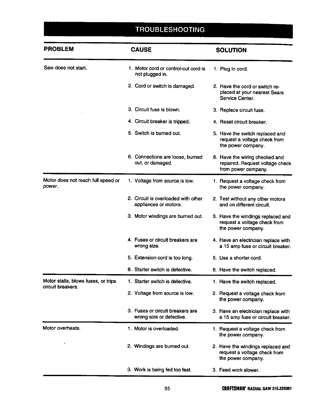
PROBLEM CAUSE SOLUTION
Saw does not start. 1, Motorcord or control-cutcord is 1, Plug incord.
not pluggedin,
2. Cord or switchis damaged. 2. Have the cord or switchre-
placed at your nearest Sears
Service Center.
3. Circuit fuse is blown. 3. Replace circuitfuse.
4. Circuit breaker is tripped. 4. Reset circuitbreaker.
5. Switch is burned out. 5. Have the switchreplaced and
request a voltage check from
the power company.
6. Connections are loose, burned
out, or damaged. 6. Have the wiringchecked and
repaired. Request voltage check
from power company.
Motor does not reach full speed or 1. Voltage from soume is low.
power. 1. Request a voltage check from
the power company.
2. Circuit is overloaded withother
appliances or motors. 2. Test without any other motors
and on different circuit.
3. Motor windings are burned out. 3. Have the windings replacedand
request a voltage check from
the power company.
4. Fuses or circuitbreakers are
wrong size. 4. Have an electrician replace with
a15 amp fuse or circuitbreaker.
5. Extensioncord is too long. 5. Use a shortercord.
6. Starter switchis defective. 6. Have the switchreplaced.
Motor stalls, blows fuses, or trips
cimuit breakers. 1. Starter switchis defective.
2. Voltage from source is low.
1. Have the switchreplaced.
2. Request a voltage check from
the power company.
3. Fuses or circuitbreakers are
wrong size or defective. 3. Have an electrician replace with
a15 amp fuse or circuitbreaker.
Motor overheats. 1. Motor is overloaded. 1. Request a voltage check from
the power company.
2. Windings are burned out. 2. Have the windings replaced and
request a voltage check from
the power company.
3. Work is beingfed too fast. 3. Feed work slower.
55 £11AFTSNAN'RADIALSAW315220381
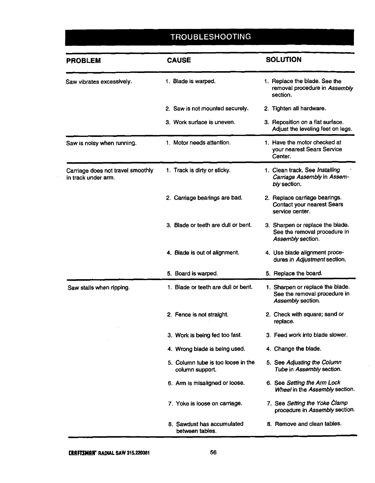
PROBLEM CAUSE SOLUTION
Saw vibrates excessively. I. Blade is warped, 1, Replace the blade. See the
removal procedurein Assembly
section.
2. Saw is not mounted securely. 2. Tighten all hardware.
3. Work surface is uneven. 3. Reposition on a flat surface.
Adjustthe leveling feet on legs.
Saw is noisywhen running.
r
Carriage does not travel smoothly
in track under arm.
1. Motor needs attention.
1, Track is dirtyor sticky.
1.
1,
Have the motor checked at
your nearest Sears Service
Center.
Clean track. See Installing
Carriage Assembly in Assem-
bly section.
2. Carriage beadngs are bad. 2. Replace carriage bearings.
Contact your nearest Sears
service center.
3. Blade or teeth are dull or bent. 3. Sharpen or replace the blade.
See the removal procedure in
Assembly section.
4. Blade is out of alignment. 4. Use blade alignment proce-
dures in Adjustment section.
5. Board is warped. 5. Replace the board.
Saw stalls when dpping. 1. Blade or teeth are dullor bent. 1. Sharpen or replace the blade.
See the removal procedure in
Assembly section.
2, Fence is notstraight. 2. Check with square; sand or
replace.
3. Work is being fed too fast. 3. Feed work into blade slower.
4. Wrong blade is being used. 4. Change the blade.
5. Column tube is too loose inthe
column support.
5. See Adjusting the Column
Tube in Assembly section.
6, Arm is misalignedor loose. 6. See Setting the Arm Lock
Wheel in the Assembly section.
7. Yoke is loose on cardage. 7. See Setting the Yoke _lamp
procedure in Assembly section.
8, Sawdust has accumulated
between tables.
8. Remove and clean tables.
rlAFTSHAN"RADIALSAW315.220381 56
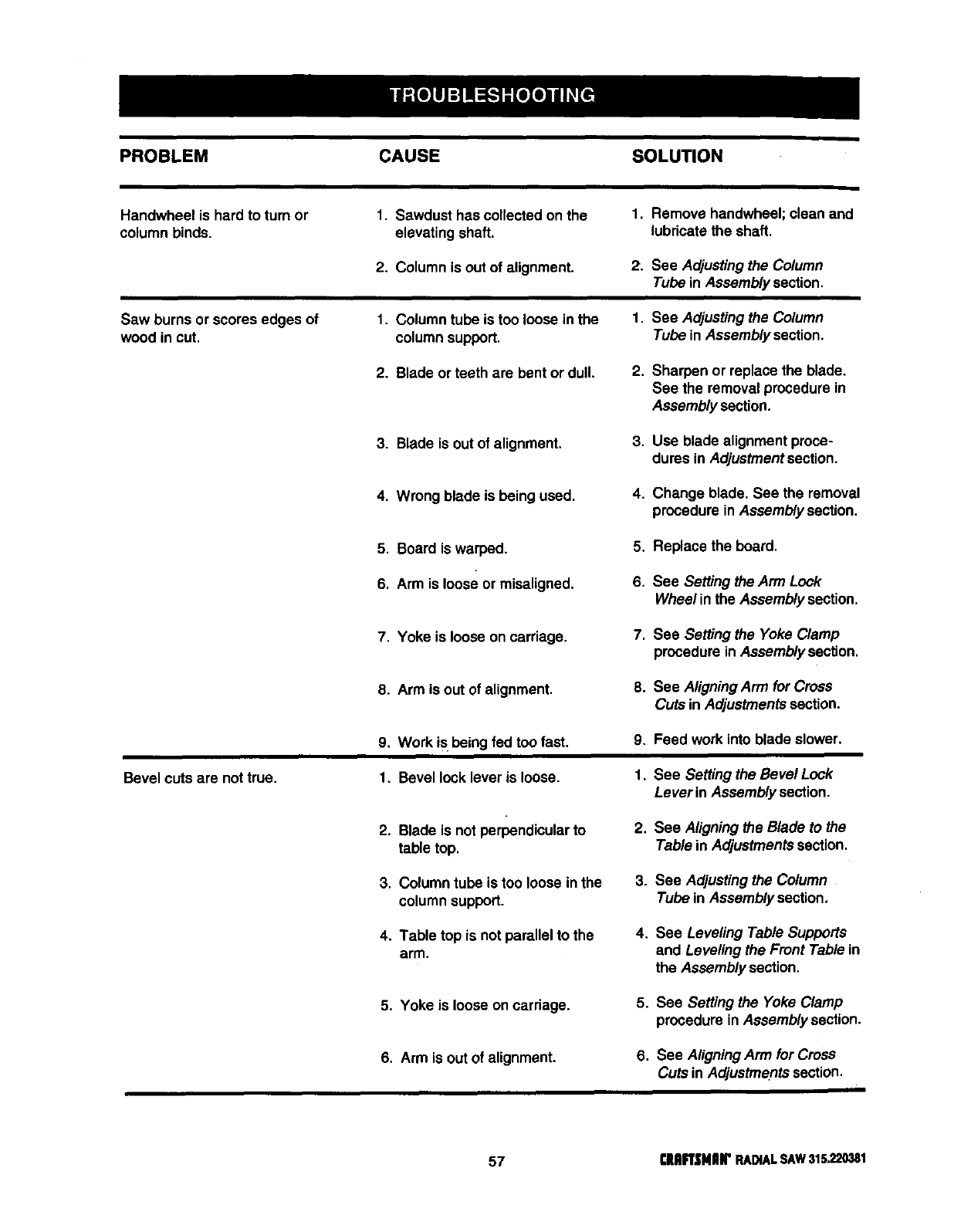
PROBLEM CAUSE SOLUTION
i
Handwheel is hard to turn or 1. Sawdust has collectedon the 1. Remove handwheel; clean and
column binds, elevating shaft, lubricate the shaft.
2. Column is out of alignment. 2. See Adjusting the Column
Tube in Assembly sectJon.
Saw burns or scores edges of 1, Column tube is too loose in the 1, See Adjusting the Column
wood in cut. columnsupport. Tube in Assembly section.
2. Blade or teeth are bent or dull. 2. Sharpen or replace the blade.
See the removal procedure in
Assembly section.
3. Blade is out of alignment. 3. Use blade alignment proce-
dures in Adjustmentsection.
4. Wrong blade is being used. 4. Change blade, See the removal
procedure in Assembly section,
5. Board is warped.
6. Arm is loose or misaligned.
5. Replace the board.
6. See Setting the Arm Lock
Wheel inthe Assembly section,
7. Yoke is loose on carriage. 7. See Setting the Yoke Clamp
procedure in Assembly section.
8. Arm is out of alignment. 8. See AligningArm for Cross
Cuts in Adjustmentssection.
Bevel cuts are nottrue.
9. Work is being fed too fast. 9.
1. Bevel lock lever is loose. 1.
2, Blade is not perpendicularto
table top,
2,
Feed work into blade slower.
See Setting the Bevel Lock
Lever in Assembly section.
See Aligningthe Blade to the
Table in Adjustments section.
3. Column tube is too loose in the
columnsupport.
3. See Adjusting the Column
Tube in Assembly section.
4. Table top is not parallel to the
arm.
4. See Leveling Table Supports
and Leveling the Front Table in
the Assembly section,
5, Yoke is loose on carriage. 5. See Setting the Yoke Clamp
procedure inAssembly section.
6. Arm is out of alignment. 6, See AligningArm for Cross
Cuts in Adjustments section.
57 €IIIIFrSMIIr RADIALSAW31s_20381
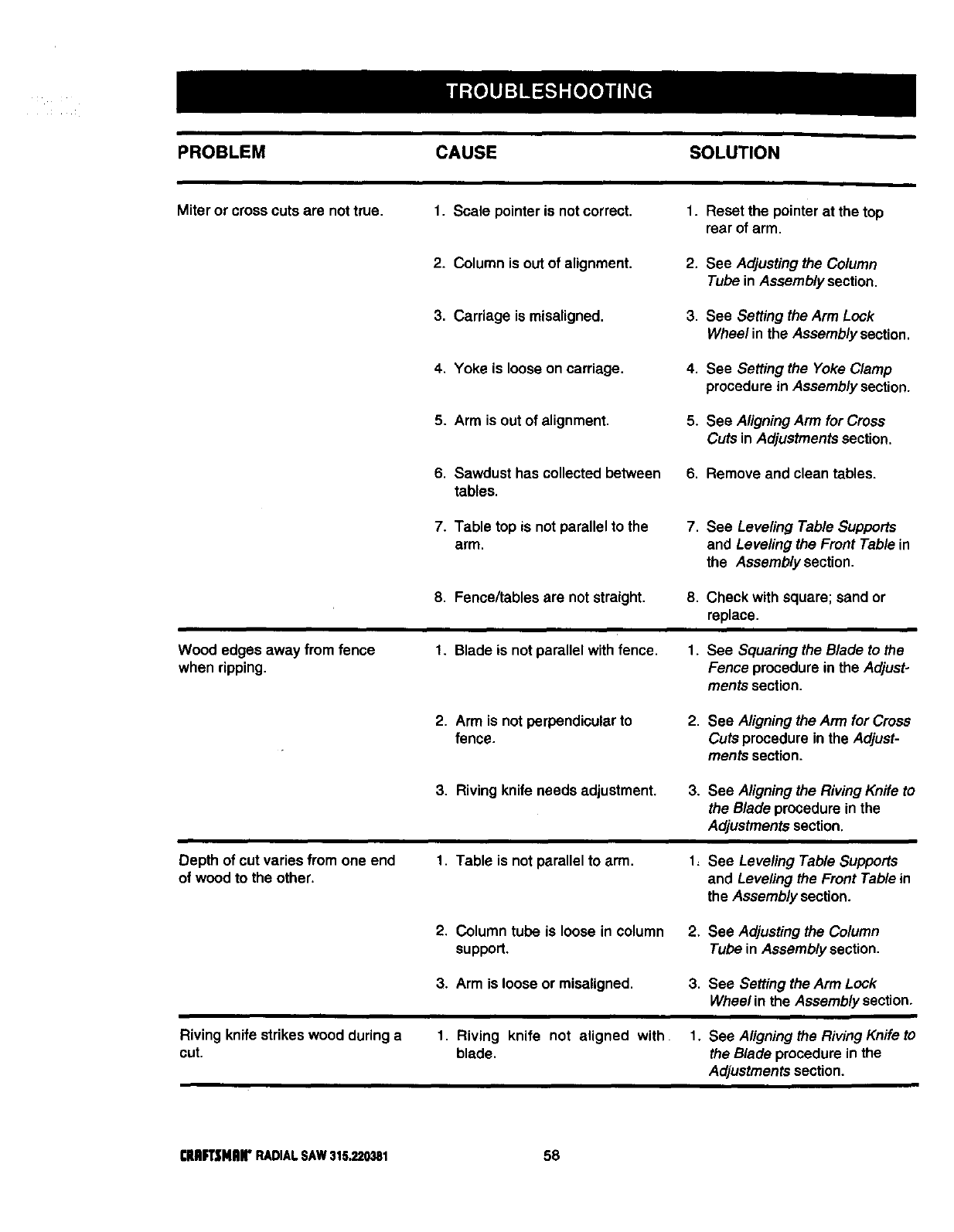
PROBLEM CAUSE SOLUTION
Miter or crosscuts are nottrue. 1. Scale pointer is not correct. 1. Reset the pointer at the top
rear of arm.
2. Column is out of alignment. 2. See Adjusting the Column
Tube in Assembly section.
3. Carriage is misaligned. 3. See Setting the Arm Lock
Wheel in the Assembly section.
4. Yoke is loose on carriage. 4. See Setting the Yoke Clamp
procedure in Assembly section.
5. Arm is outof alignment. 5. See AligningArm forCross
Cuts in Adjustmentssection.
6. Sawdust has collected between 6. Remove and clean tables.
tables.
7. Table top is not parallel to the
arm. 7. See Leveling Table Supports
and Leveling the Front Table in
the Assembly section,
8. Fence/tables are not straight. 8. Check with square; sand or
replace.
Wood edges away from fence
when ripping.
t. Blade is not parallel withfence. 1. See Squaring the Blade to the
Fence procedurein the Adjust-
ments section.
2. Arm is notperpendicular to
fence. 2. See Aligning the Arm for Cross
Cuts procedure in the Adjust-
ments section.
3. Riving knife needs adjustment. 3. See Aligning the RivingKnife to
the Blade procedurein the
Adjustments section.
Depth of cut varies from one end
of wood to the other. 1. Table is not parallel to arm, 1= See Leveling Table Supports
and Leveling the Front Table in
the Assembly section.
2. Column tube is loose in column 2. See Adjusting the Column
support. Tube in Assembly section,
3. Arm is loose or misaligned. 3. See Setting the Arm Lock
Wheel in the Assembly section,
Riving knifestrikes wood during a
cut. 1. Riving knife not aligned with. 1. See Aligningthe Riving Knife to
blade, the Blade procedure in the
Adjustmentssection.
CUKsNArRADIALSAW315.220381 58
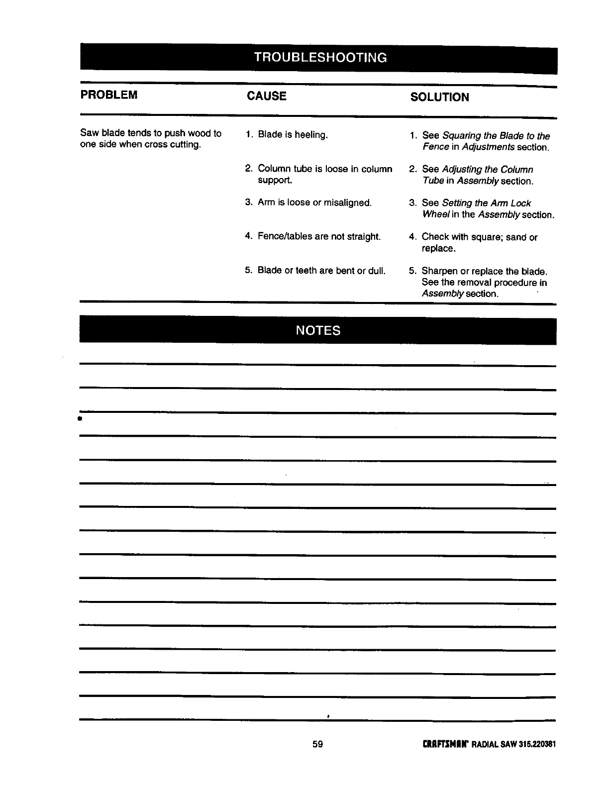
PROBLEM CAUSE SOLUTION
Saw blade tends to push wood to 1. Blade is heeling. 1. See Squaring the Blade to the
one side when cross cutting. Fence in Adjustmentssection.
2. Column tube is loose in column 2. See Adjusting the Column
support. Tube in Assembly section.
3. Arm is loose or misaligned. 3. See Setting the Arm Lock
Wheel in the Assembly section.
4. Fence/tables are notstraight. 4. Check with square; sand or
replace.
5. Blade or teeth are bentor dull. 5. Sharpen or replace the blade.
See the removal procedure in
Assembly section.
59 rRAFt'_;MAN"RADIALSAW315.220381
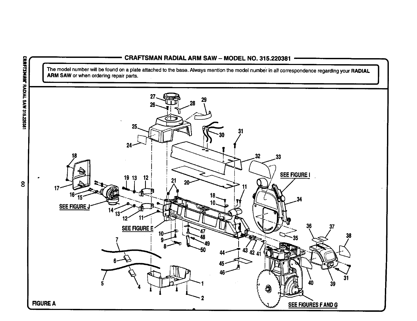
=*
.=
O)
C)
CRAFTSMAN RADIAL ARM SAW- MODEL NO. 315.220381
I he model numberwillbe found on a plate attached to the base. Always mentionthe model numberin all correspondence regarding your RADIAL I
ARM SAW orwhen ordering repair parts. J
RGURE A
19 13 12
SEERGUREE
7
31
/
11
SEEFIGUREI
36 37
"35 38
48 39
SEEFIGURESFANDG
31
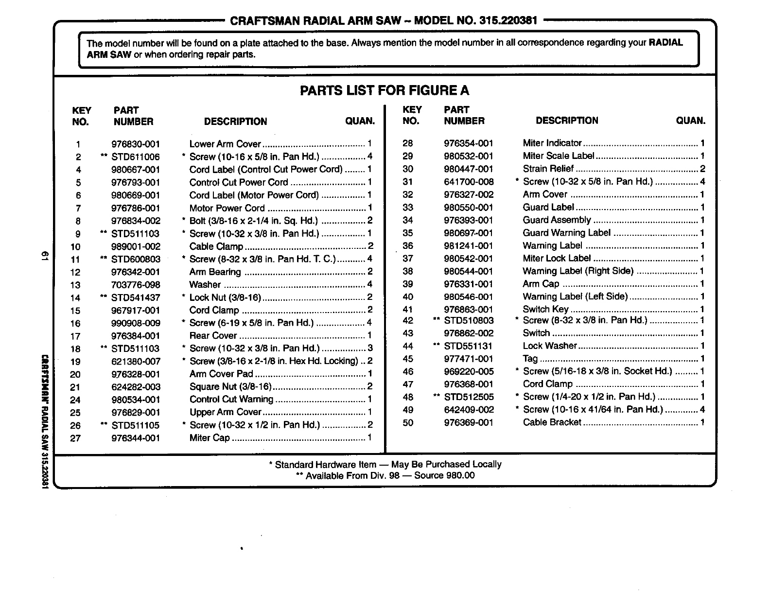
CRAFTSMANRADIAL ARM SAW- MODELNO. 315.220381
]
IThe model number willbe found on a plate attachedto the base. Always mentionthe model number in all correspondenceregardingyour RADIAL I
_ARM SAW or when ordering repair parts. I
=.
!
KEY PART
NO. NUMBER
1 976830-001
2 **STD611006
4 980667-001
5 976793-001
6 980669-001
7 976786-001
8 976834-002
9 **STD611103
10 989001-002
11 ** STD600803
12 976342-001
13 703776-098
14 ** STD541437
15 967917-001
16 990908-009
17 976384-001
18 ** STD511103
19 621380-007
20 976328-001
21 624282-003
24 980534-001
25 976829-001
26 ** STD511105
27 976344-001
PARTS LIST FOR FIGURE A
KEY PART
DESCRIPTION QUAN.
LowerArm Cover ........................................ 1
* Screw (10-16 x 5/8 in. Pan Hd.) ................. 4
Cord Label (Control Cut Power Cord) ........ 1
Control Cut Power Cord ............................. 1
Cord Label (Motor Power Cord) ................. 1
Motor Power Cord ...................................... "1
* Bolt (3/8-16 x 2-1/4 in. Sq. Hd.) ................. 2
* Screw (10-32 x 318in. Pan Hd.) ................. 1
Cable Clamp ............................................... 2
* Screw (8-32 x 3/8 in. Pan Hd, T. C.) ........... 4
Arm Bearing ............................................... 2
Washer ....................................................... 4
* LockNut (3/8-16) ........................................ 2
Cord Clamp ................................................ 2
* Screw (6-19 x 5/8 in. Pan Hd.) ................... 4
Rear Cover ................................................. 1
* Screw (10-32 x 318in. Pan Hd.) ................. 3
*Screw (3/8-16 x 2-1/8 in. Hex Hd, Locking)..2
Arm Cover Pad ........................................... 1
Square Nut (3/8-16) .................................... 2
ControlCut Warning ................................... 1
UpperArm Cover ........................................ 1
* Screw (10-32 x 1/2 in. Pan Hd.) ................. 2
Miter Cap .................................................... 1
NO. NUMBER DESCRIPTION QUAN,
28 976354-001
29 980532-001
30 980447-001
31 641700-008
32 976327-002
33 980550-001
34 976393-001
35 980697-001
36 981241-001
37 980542-001
38 980544-001
39 976331-001
40 980546-001
41 976863-001
42 ** STD510803
43 976862-002
44 ** STD551131
45 977471-001
46 969220-005
47 976368-001
48 ** STD512505
49 642409-002
50 976369-001
* Standard Hardware Item -- May Be Purchased Locally
** Available From Div. 98 -- Source 980.00
Miter Indicator............................................. 1
Miter Scale Label ........................................ 1
Strain Relief ................................................ 2
* Screw (10-32 x 5/8 in. Pan Hd.) ................. 4
Arm Cover ..................................................
Guard Label ................................................
Guard Assembly .........................................
Guard Warning Label .................................
Warning Label ............................................
Miter Lock Label .........................................
Waming Label (Right Side) ........................
Arm Cap .....................................................
Warning Label (Left Side) ...........................
Switch Key ..................................................
* Screw (8-32 x 3/8 in. Pan Hd.) ...................
Switch .........................................................
Lock Washer ...............................................
Tag ..............................................................
* Screw (5/16-18 x 3/8 in. Socket Hd.) .........
Cord Clamp ................................................
* Screw (1/4-20 x 1/2 in. Pan Hd.) ................
* Screw (10-16 x 41/64 in. Pan Hd.) ............. 4
Cable Bracket ............................................. 1
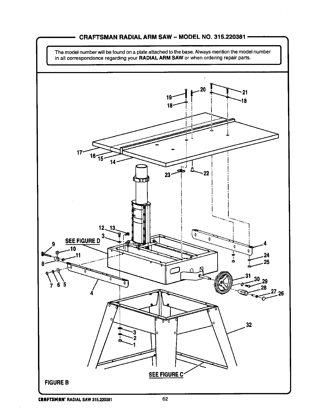
CRAFTSMAN RADIAL ARM SAW -MODEL NO. 315.220381
I The model number will be found on aplate attached to the base, Always mention the model number I
in all correspondence regarding your RADIAL ARM SAW or when ordering repair parts. J
I
SEE FIGt
14
65
4
FIGUREB
CRAFTSMRN"RADIALSAW315.220381
SEEFIGUREC
62
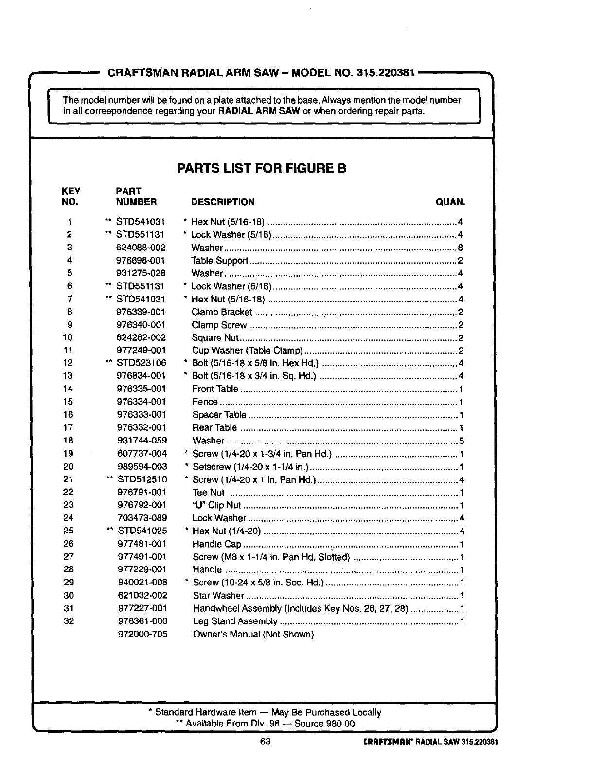
CRAFTSMAN RADIAL ARM SAW - MODEL NO. 315.220381
I he model numberwill be found on aplate attached to the base. Always mention the model number I
in all correspondence regarding your RADIAL ARM SAW or when ordering repair parts.
PARTS LIST FOR FIGURE B
KEY PART
NO. NUMBER DESCRIPTION QUAN.
1 ** STD541031
2** STD551131
3624088-OO2
4976698~001
5 931275-028
6 ** STD551131
7 ** STD541031
8 976339-001
9 976340-001
10 624282-002
11 977249-001
12 ** STD523106
13 976834-001
14 976335-001
15 976334-001
16 976333-001
17 976332-001
18 931744-059
19 607737-004
20 989594-003
21 ** STD512510
22 976791-001
23 976792-001
24 703473-089
25 ** STD541025
26 977481-001
27 977491-001
28 977229-001
29 940021-008
30 621032-002
31 977227-001
32 976361-000
972000-705
*Hex Nut (5/16-18) .......................................................................... 4
* Lock Washer (5/16) ........................................................................ 4
Washer ........................................................................................... 8
Table Support ................................................................................. 2
Washer ........................................................................................... 4
* Lock Washer (5/16) ........................................................................ 4
* Hex Nut (5/16-18) .......................................................................... 4
Clamp Bracket ............................................................................... 2
Clamp Screw ................................................................................. 2
Square Nut ..................................................................................... 2
Cup Washer (Table Clamp) ............................................................ 2
*Bolt (5/16-18 x 5/8 in. Hex Hd.) ..................................................... 4
*Bolt (5/16-18 x 3/4 in. Sq. Hd.) ...................................................... 4
Front Table ..................................................................................... 1
Fence ............................................................................................. 1
Spacer Table .................................................................................. 1
Rear Table ..................................................................................... 1
Washer ........................................................................................... 5
* Screw (1/4-20 x 1-3/4 in. Pan Hd.) ................................................ 1
* Setscrew (1/4-20 x 1-1/4 in.) .......................................................... 1
* Screw (1/4-20 x 1 in. Pan Hd.) ....................................................... 4
Tee Nut .......................................................................................... 1
"U" Clip Nut .................................................................................... 1
Lock Washer .................................................................................. 4
* Hex Nut (1/4-20) ............................................................................ 4
Handle Cap .................................................................................... 1
Screw (M8 x 1-1/4 in. Pan Hd. Slotted) ......................................... 1
Handle ........................................................................................... 1
* Screw (10-24 x 5/8 in. Soc. Hd.) .................................................... 1
Star Washer ................................................................................... 1
Handwheel Assembly (Includes Key Nos. 26, 27, 28) ................... 1
Leg Stand Assembly ...................................................................... 1
Owner's Manual (Not Shown)
*Standard Hardware Item -- May Be Purchased Locally
** Available From Div. 98 -- Source 980.00 i
63 CRRFTSMRN"RADIALSAW315.220381
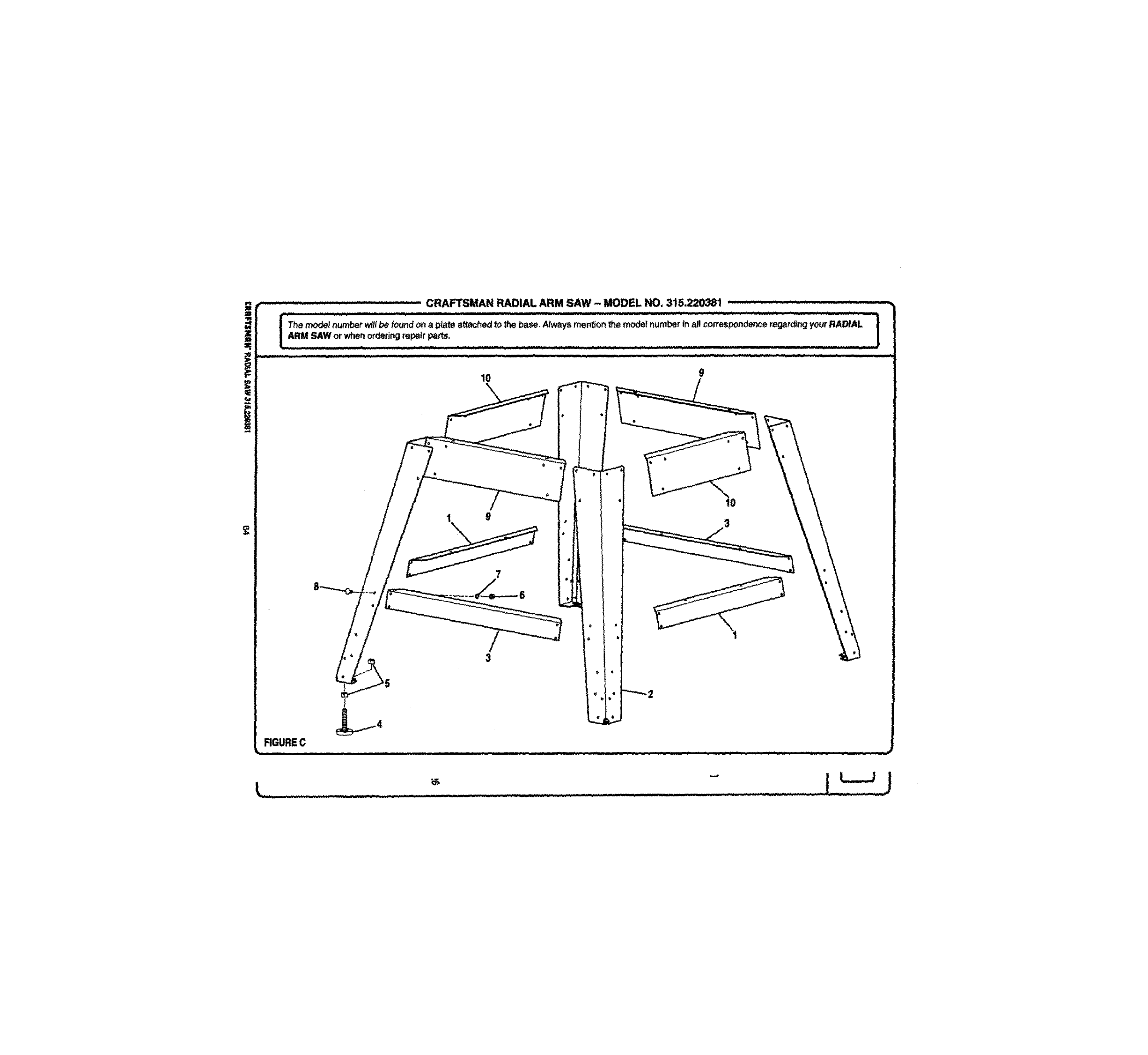
r" :::- _ ..................... CRAFTSMAN RADIAL ARM SAW - MODEL NO,, 315.220381 -.... :....-
j_Them_de.numberw_i_bef_und_nap.atea_a_chedt_theba_A_waysmen_i_n_e_num_rin_c_rr_nde_r_rd._rR_ALI'_ .| ARM SAW or whe,.norderingrepair pa_ts.
=, .'.... '.'.'.- . ::::: :::: : :, i i:,:::-; :::: : :: ::: : :
FIGUREC
i i i i
10 9
10
19
7
i i i i iii ii iii i iiiii iiiii i ii ii iii
3
\
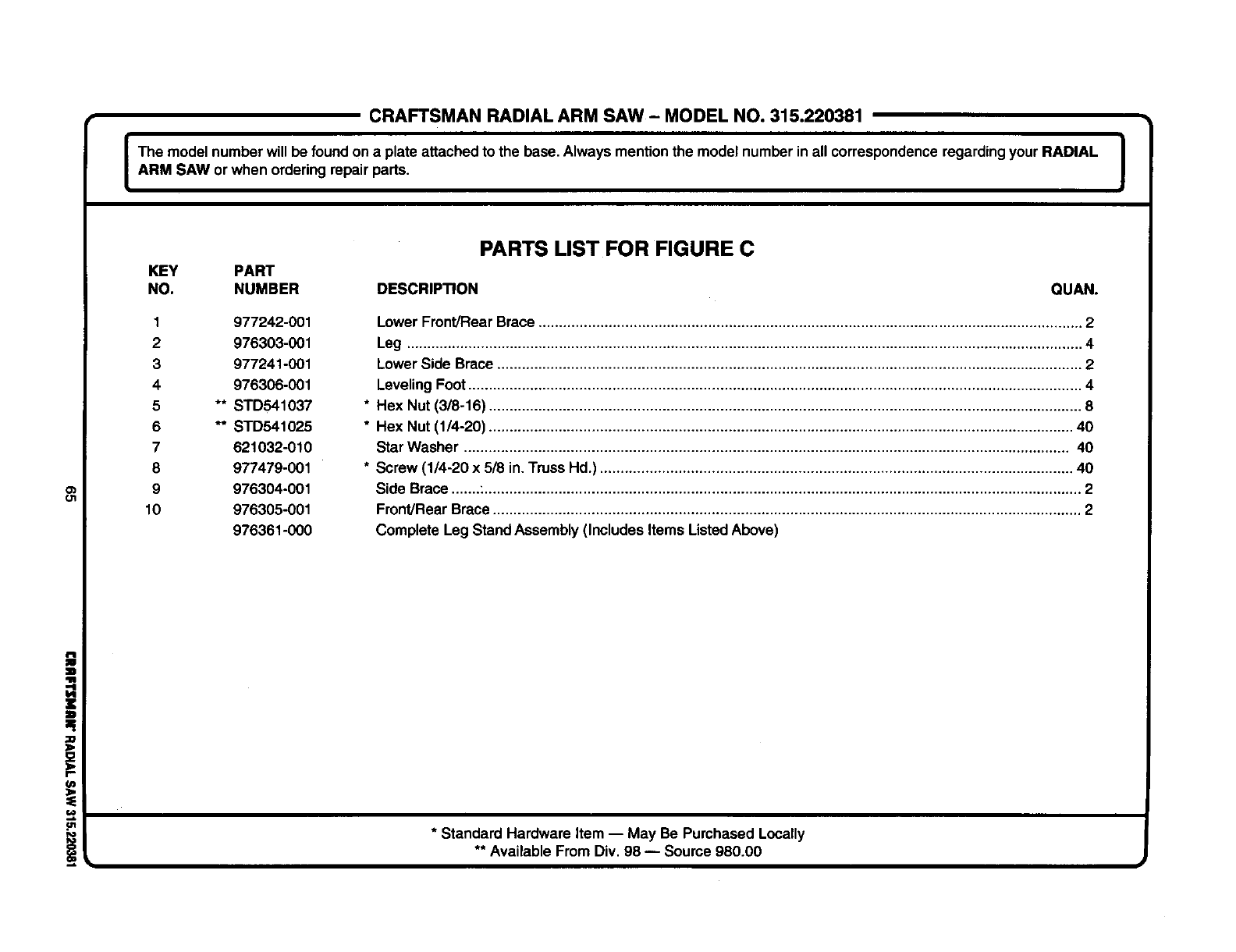
CRAFTSMAN RADIAL ARM SAW - MODEL NO. 315.220381
I The model number will be foundon a plate attached to the base. Always mention the model number in all correspondenceregarding your RADIAL I
i
ARM SAW orwhen ordering repair parts. J
O_
ol
f/)
PARTS LIST FOR FIGURE C
KEY PART
NO. NUMBER DESCRIP_ON QUAN.
1 977242-001
2 976303-001
3 977241-001
4 976306-001
5 ** STD541037
6** STD541025
7 621032-010
8 977479-001
9 976304-001
10 976305-001
976361-000
Lower Front/Rear Brace .................................................................................................................................... 2
Leg .................................................................................................................................................................... 4
Lower Side Brace .............................................................................................................................................. 2
Leveling Foot ..................................................................................................................................................... 4
* Hex Nut (3/8-16) ................................................................................................................................................ 8
* Hex Nut (1/4-20) .............................................................................................................................................. 40
Star Washer ................................................................................................................................................... 40
* Screw (1/4-20 x 5/8 in. Truss Hd.) ................................................................................................................... 40
Side Brace .......:................................................................................................................................................. 2
Front/Rear Brace............................................................................................................................................... 2
Complete Leg Stand Assembly (Includes Items ListedAbove)
* Standard Hardware Item -- May Be Purchased Locally
** Available From Div. 98 -- Source 980.00
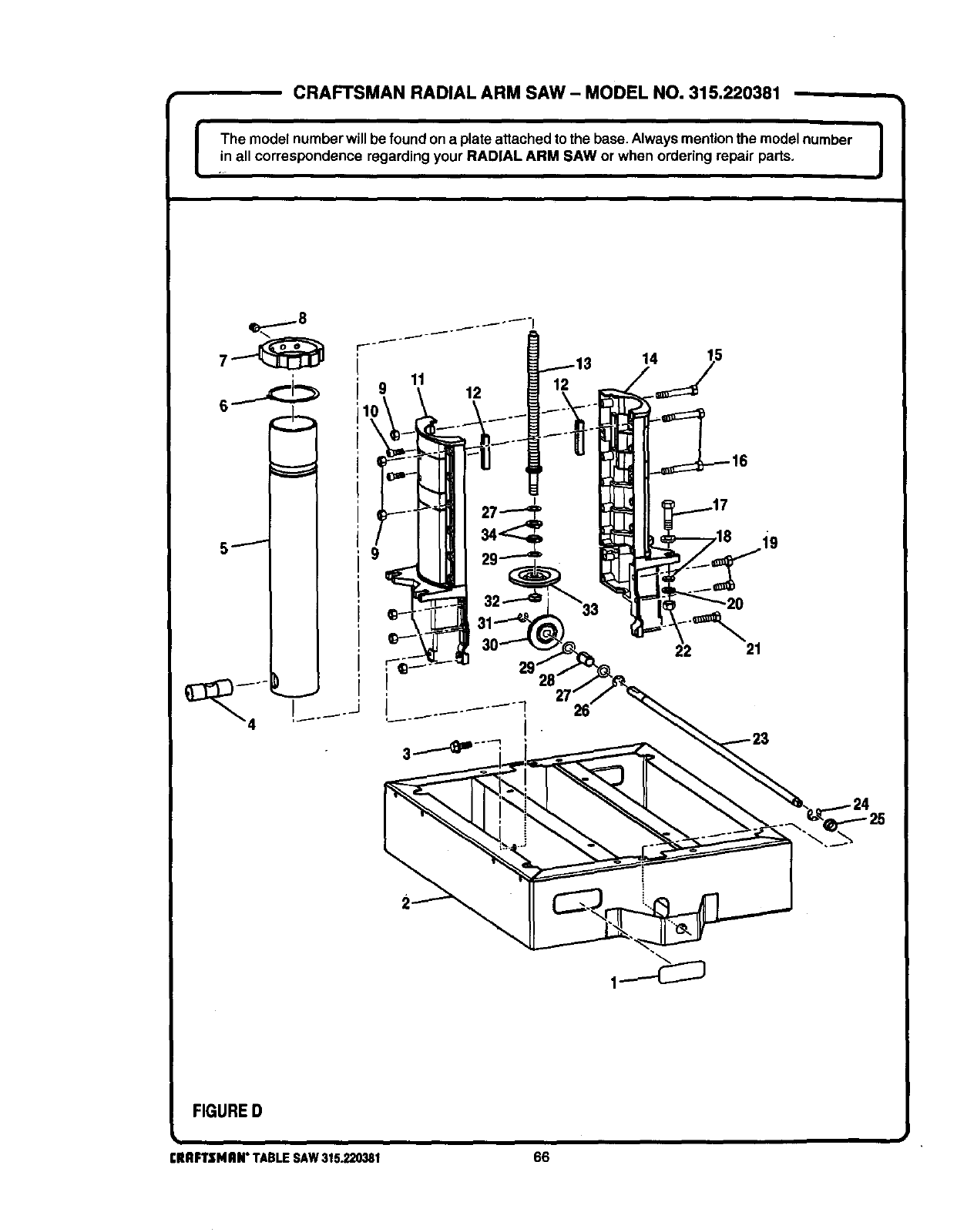
ICRAFTSMAN RADIAL ARM SAW - MODEL NO. 315.220381
The model numberwill be foundon a plate attachedto the base.Alwaysmentionthe model number
in all correspondence regarding your RADIAL ARM SAW or when ordering repair parts. I
qp.......- 8
11 12
14
22 21
FIGURED
ClUlFTSMAN"TABLESAW315.220381 66
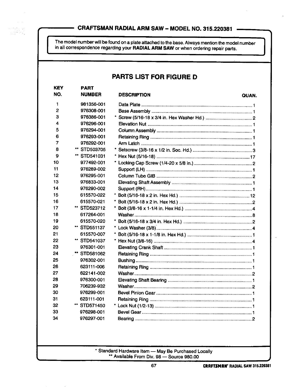
CRAFTSMAN RADIAL ARM SAW - MODEL NO. 315.220381
IThe model numberwill be foundon a plate attachedto the base. Always mentionthe model number ]in all correspondence regarding your RADIAL ARM SAW or when ordering repair parts. I
PARTS LIST FOR FIGURE D
KEY PART
NO. NUMBER DESCRIPTION QUAN.
1 981356-001
2 976308-001
3 976386-001
4 976296-001
5 976294-001
6 976293-001
7 976292-001
8 ** STD503705
9 ** STD541031
10 977492-001
11 976289-002
12 976295-001
13 976833-001
14 976290-002
15 615570-022
16 615570-021
17 ** STD523712
18 617264-001
19 615570-020
20 ** STD551137
21 615570-007
22 ** STD541037
23 976301-001
24 ** STD581062
25 976302-001
26 623111-006
27 622141-002
28 976300-001
29 706239-932
30 976299-001
31 623111-001
32 ** STD571450
33 976298-001
34 976297-001
Data Plate ...................................................................................... 1
Base Assembly .............................................................................. 1
* Screw (5/16-18 x 3/4 in. Hex Washer Hd.) .................................... 2
ElevationNut ................................................................................. 1
Column Assembly .......................................................................... 1
RetainingRing ............................................................................... 1
Arm Latch ...................................................................................... 1
* Setscrew (3/8-16 x 1/2 in. Soc. Hd.) .............................................. 3
* Hex Nut (5/16-18) ........................................................................ 17
* LockingCap Screw (1/4-20 x 5/8 in.) ............................................. 2
Support (LH) .................................................................................. 1
ColumnTube GIB .......................................................................... 2
ElevatingShaft Assembly .............................................................. 1
Support (RH) .................................................................................. 1
* Belt (5/16-18 x 2 in. Hex Hd.) ...................................................... 12
* Bolt (5/16-18 x 2 in. Hex Hd.) ........................................................ 2
* Bolt (3/8-16 x 1-1/4 in. Hex Hd.) .................................................... 4
Washer ........................................................................................... 8
* Bolt (5/16-18 x 3/4 in. Hex Hd.) ..................................................... 2
*LockWasher (3/8). ......................................................................... 4
* Belt (5/16-18 x 1-1/8 in. Hex Hd.) .................................................. 1
* Hex Nut (3/8-16) ............................................................................ 4
ElevatingCrank Shaft .................................................................... 1
Retaining Ring ............................................................................... 1
Bushing .......................................................................................... 1
Retaining Ring ............................................................................... 1
Washer ........................................................................................... 2
ElevatingShaft Beadng ................................................................. 1
Washer ........................................................................................... 2
Bevel Pinion Gear .......................................................................... 1
Retaining Ring ............................................................................... 1
* Lock Nut (1/2-13) ........................................................................... 1
Bevel Gear ..................................................................................... 1
Bearing .......................................................................................... 2
* Standard Hardware Item -- May Be Purchased Locally
** Available From Div. 98 -- Soume 980.00
67 CRRFTSNHN"RADIALSAW315220381
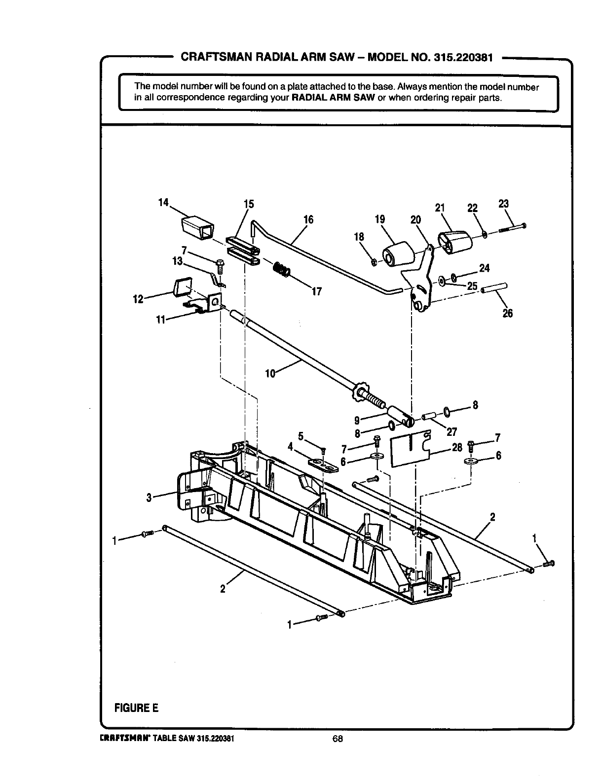
CRAFTSMAN RADIAL ARM SAW - MODEL NO. 315.220381 -,
J The model numberwillbe found on a plate attached to the base.Alwaysmentionthe model number J
in all correspondence regarding your RADIAL ARM SAW or when ordering repair parts.
15 21 22 23
16 19 20
18
\
26
2
FIGUREE
i
rltRFlrSMRN" TABLESAW315.220381 68
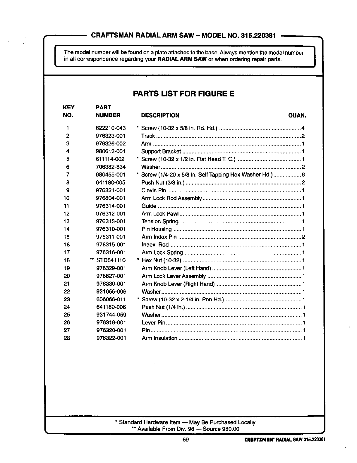
CRAFTSMAN RADIAL ARM SAW- MODEL NO. 315.220381
The model numberwill be found ona plate attachedto the base.Alwaysmentionthe modelnumber !
in all correspondence regarding your RADIAL ARM SAW or when ordering repair parts.
PARTS LIST FOR FIGURE E
KEY PART
NO. NUMBER DESCRIPTION QUAN.
1 622210-043
2976323-001
3976326-002
4980613-001
5 611114-002
6 706382-834
7 980455-001
8 641180-005
9 976321-001
10 976804-001
11 976314-001
12 976312-001
13 976313-001
14 976310-001
15 976311-001
16 976315-001
17 976316-001
18 ** STD541110
19 976329-001
20 976827-001
21 976330-001
22 931055-006
23 606066-011
24 641180-006
25 931744-059
26 976319-001
27 976320-001
28 976322-001
* Screw (10-32 x 5/8 in. Rd. Hd.) ..................................................... 4
Track .............................................................................................. 2
Arm ................................................................................................ 1
Support Bracket............................................................................. 1
* Screw (10-32 x 1/2 in. Flat Head T. C.) .......................................... 1
Washer ........................................................................................... 2
* Screw (1/4-20 x 5/8 in. Self Tapping Hex Washer Hd.) .................. 6
Push Nut (3/8 in.) ........................................................................... 2
Clevis Pin ....................................................................................... 1
Arm Lock Rod Assembly ................................................................ 1
Guide ............................................................................................. 1
Arm Lock Pawl ............................................................................... 1
Tension Spring ............................................................................... 1
Pin Housing ................................................................................... 1
Arm Index Pin ................................................................................ 2
Index Rod ..................................................................................... 1
Arm Lock Spring ............................................................................ 1
* Hex Nut (10-32) ............................................................................. 1
Arm Knob Lever (Left Hand) .......................................................... 1
Arm Lock LeverAssembly ............................................................. 1
Arm Knob Lever (Right Hand) ....................................................... 1
Washer ........................................................................................... 1
* Screw (10-32 x 2-1/4 in. Pan Hd.) ................................................. 1
Push Nut (1/4 in.) ........................................................................... 1
Washer ........................................................................................... 1
Lever Pin ........................................................................................ 1
Pin .................................................................................................. 1
Arm Insulation ................................................................................ 1
* Standard Hardware Item -- May Be Purchased Locally
** Available From Div. 98 -- Source 980.00
69 CRAFTSNAIr RADIALSAW315.220381
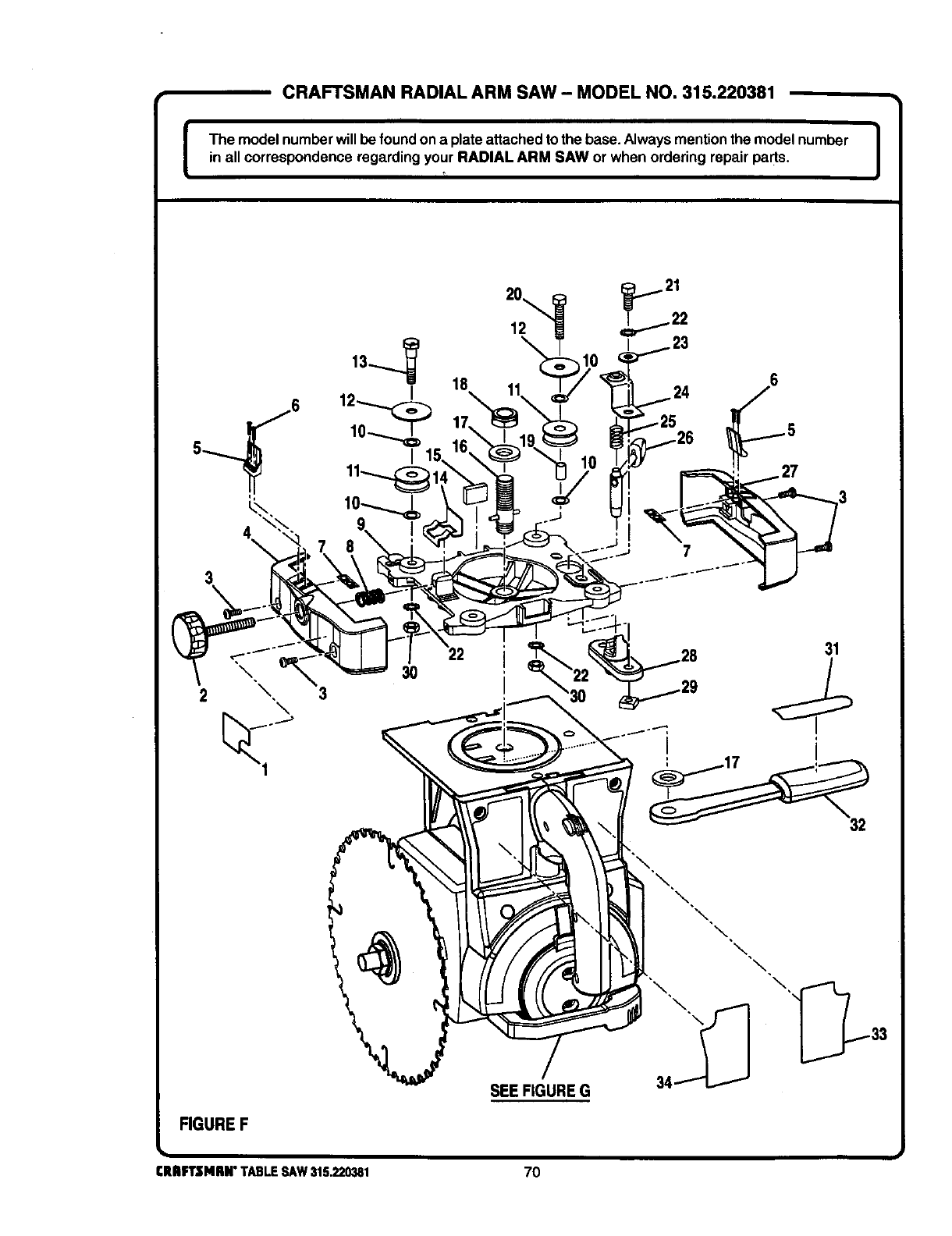
CRAFTSMAN RADIAL ARM SAW- MODEL NO. 315.220381
The model numberwillbe foundon a plateattachedto the base.Always mentionthe model number 1
in all correspondence regarding your RADIAL ARM SAW or when ordering repair pads. I
4\
3
7
6
31
\, 30
\, 3
\
FIGUREF
SEE FIGURE G
CRRFTSMRN"TABLESAW315.220381 70
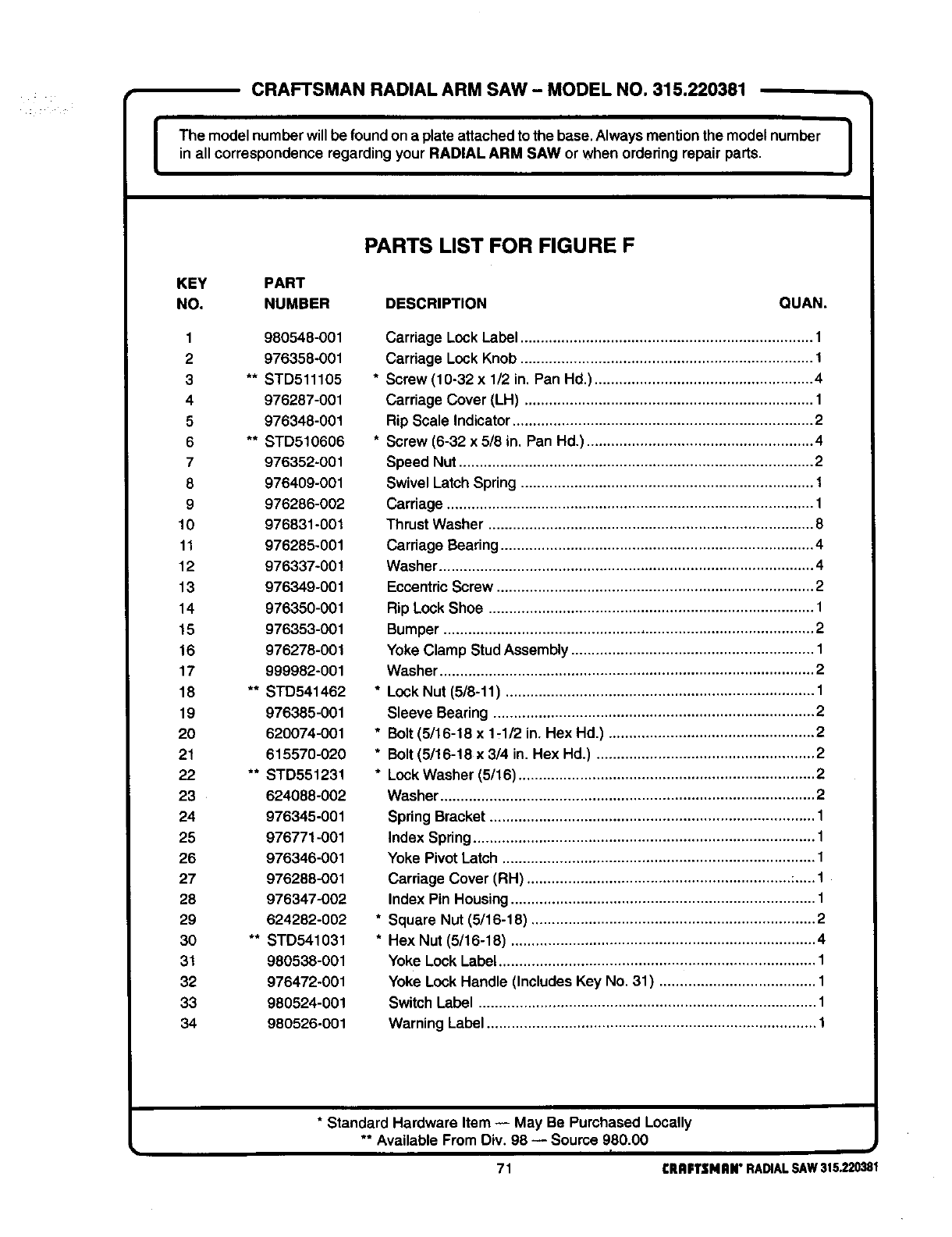
CRAFTSMAN RADIAL ARM SAW - MODEL NO. 315.220381
IThe model numberwill be foundon a plate attachedto the base.Always mentionthe model number 1
in all correspondence regarding your RADIAL ARM SAW or when ordering repair parts, I
PARTS LIST FOR FIGURE F
KEY PART
NO. NUMBER DESCRIPTION QUAN.
1980548-001
2 976358-001
3** STD511105
4 976287-001
6 976348-001
6 ** STD510606
7 976352-001
8 976409-001
9 976286-002
10 976831-001
11 976285-001
12 976337-001
13 976349-001
14 976350-001
15 976353-001
16 976278-001
17 999982-001
18 ** STD541462
19 976385-001
20 620074-001
21 615570-020
22 ** STD551231
23 624088-002
24 976345-001
25 976771-001
26 976346-001
27 976288-001
28 976347-002
29 624282-002
30 ** STD541031
31 980538-001
32 976472-001
33 980524-001
34 980526-001
Carriage Lock Label ....................................................................... 1
Carriage Lock Knob ....................................................................... 1
* Screw (10-32 x 1/2 in. Pan Hd.) ..................................................... 4
Carriage Cover (LH) ...................................................................... 1
Rip Scale Indicator ......................................................................... 2
* Screw (6-32 x 5/8 in. Pan Hd.) ....................................................... 4
Speed Nut ...................................................................................... 2
Swivel Latch Spring ....................................................................... 1
Carriage ......................................................................................... 1
Thrust Washer ............................................................................... 8
Carriage Bearing ............................................................................ 4
Washer ........................................................................................... 4
Eccentric Screw ............................................................................. 2
Rip Lock Shoe ............................................................................... 1
Bumper .......................................................................................... 2
Yoke Clamp Stud Assembly ........................................................... 1
Washer ........................................................................................... 2
* Lock Nut (5/8-11) ........................................................................... 1
Sleeve Bearing .............................................................................. 2
* Bolt (5/16-18 x 1-1/2 in. Hex Hd.) .................................................. 2
* Bolt (5/16-18 x3/4 in. Hex Hd,) ..................................................... 2
* Lock Washer (5/16) ........................................................................ 2
Washer ........................................................................................... 2
Spring Bracket ............................................................................... 1
Index Spring ................................................................................... 1
Yoke Pivot Latch ............................................................................ 1
Carriage Cover (RH) ................................................................ :..... 1
Index Pin Housing .......................................................................... 1
* Square Nut (5/16-18) ..................................................................... 2
* Hex Nut (5/16-18) .......................................................................... 4
Yoke Lock Label ............................................................................. 1
Yoke Lock Handle (Includes Key No. 31) ...................................... 1
Switch Label .................................................................................. 1
Warning Label ................................................................................ 1
*Standard Hardware Item -- May Be Purchased Locally
** Available From Div. 98 -- Source 980.00
71 CRAFTSMAN"RADIALSAW315.220381
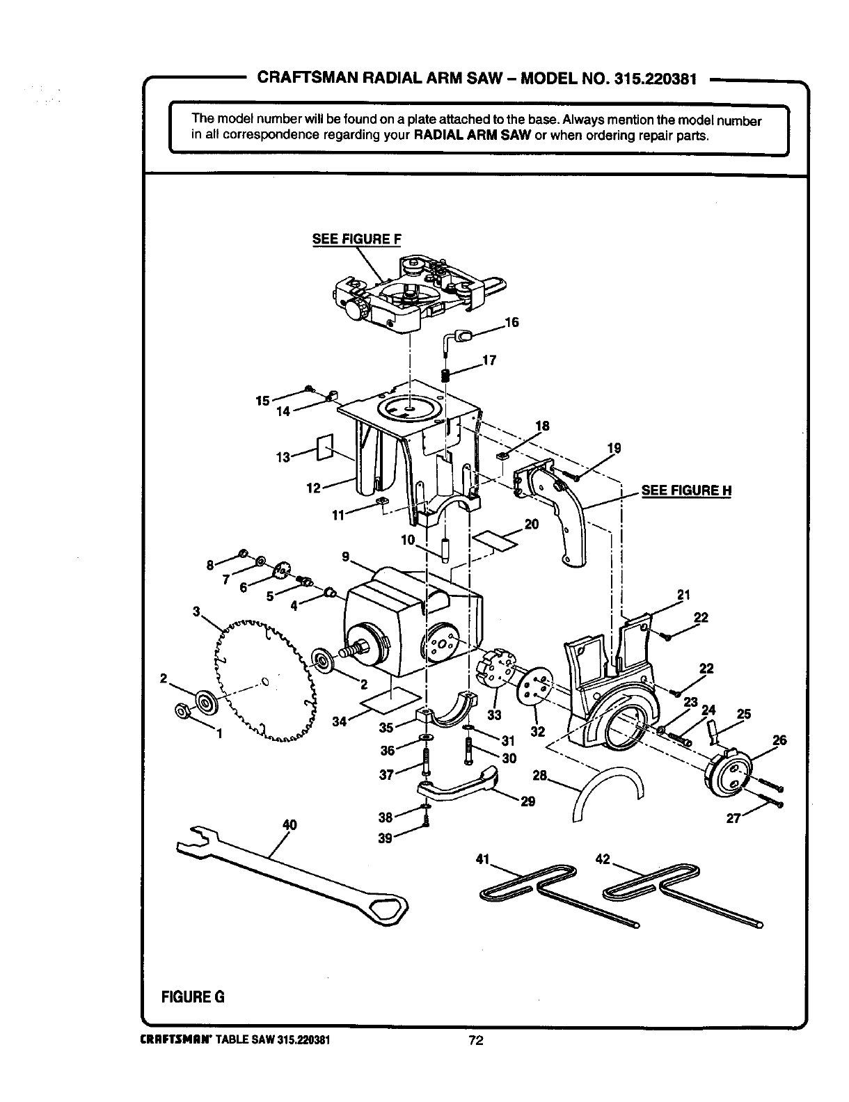
CRAFTSMAN RADIAL ARM SAW - MODEL NO. 315.220381
I The model numberwill be foundon a plateattached tothe base.Always mentionthe model number |
in all correspondence regarding your RADIAL ARM SAW or when ordering repair parts. I
SEE FIGURE F
19
._. _SEEFIGUREH
21
22
22
24 25
FIGUREG
26
I
CRAFTSMAN"TABLESAW315,220381 72
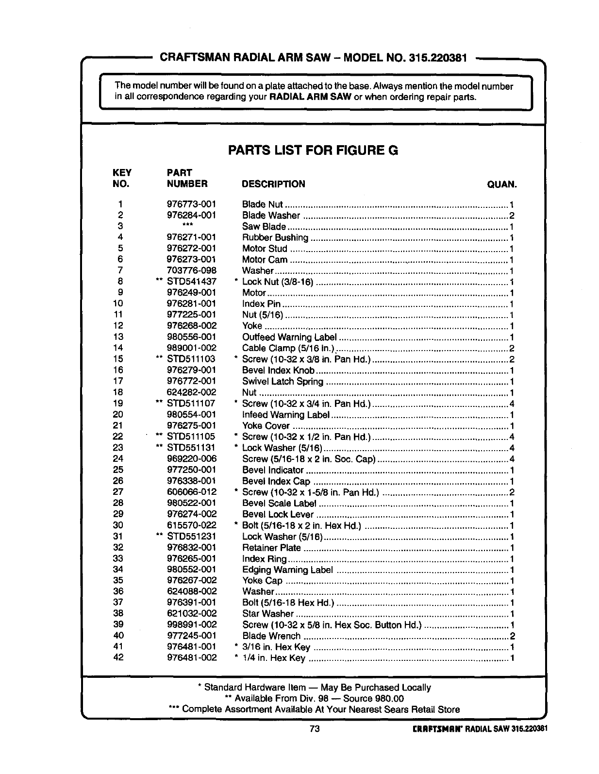
CRAFTSMAN RADIAL ARM SAW - MODEL NO. 315.220381
The model number willbe found onaplateattached to the base. Always mention the model number 1
in all correspondence regarding your RADIAL ARM SAW or when ordering repair parts.
PARTS LIST FOR FIGURE G
KEY PART
NO. NUMBER DESCRIPTION QUAN.
1976773-001
2 976284-001
4 976271-001
5 976272-001
6 976273-001
7 703776-098
8 ** STD541437
9 976249-001
10 976281-001
11 977225-001
12 976268-002
13 980556-001
14 989001-002
15 ** STD511103
16 976279-001
17 976772-001
18 624282-002
19 ** STD511107
20 980554-001
21 976275-001
22 "** STD511105
23 ** STD551131
24 969220-006
25 977250-001
26 976338-001
27 606066-012
28 980522-001
29 976274-002
30 615570-022
31 ** STD551231
32 976832-001
33 976265-001
34 980552-001
35 976267-002
36 624088-002
37 976391-001
38 621032-002
39 998991-002
40 977245-001
41 976481-001
42 976481-002
Blade Nut ....................................................................................... 1
Blade Washer ................................................................................ 2
Saw Blade ...................................................................................... 1
Rubber Bushing ............................................................................. 1
Motor Stud ..................................................................................... 1
Motor Cam ..................................................................................... 1
Washer ........................................................................................... 1
* Lock Nut (3/8-16) ........................................................................... 1
Motor .............................................................................................. 1
Index Pin ........................................................................................ 1
Nut (5/16) ....................................................................................... 1
Yoke ............................................................................................... 1
Outfeed Warning Label .................................................................. 1
Cable Clamp (5/16 in.). .................................................................. 2
* Screw (10-32 x3/8 in. Pan Hd.) ..................................................... 2
Bevel Index Knob ........................................................................... 1
Swivel Latch Spring ....................................................................... 1
Nut ................................................................................................. 1
* Screw (10-32 x 3/4 in. Pan Hd,) ..................................................... 4
Infeed Warning Label ..................................................................... 1
Yoke Cover .................................................................................... 1
* Screw (10-32 x 1/2 in. Pan Hd.) ..................................................... 4
* Lock Washer (5/16) ........................................................................ 4
Screw (5/16-18 x 2 in. Soc. Cap) ................................................... 4
Bevel Indicator ............................................................................... 1
Bevel Index Cap ............................................................................ 1
* Screw (10-32 x 1-5/8 in. Pan Hd.) ................................................. 2
Bevel Scale Label .......................................................................... 1
Bevel Lock Lever ........................................................................... 1
* Bolt (5/16-18 x 2 in. Hex Hd.) ........................................................ 1
Lock Washer (5/18) ........................................................................ 1
Retainer Plate ................................................................................ 1
Index Ring ...................................................................................... 1
Edging Warning Label ................................................................... 1
Yoke Cap ....................................................................................... 1
Washer ........................................................................................... 1
Belt (5/16-18 Hex Hd.) ................................................................... 1
Star Washer ................................................................................... 1
Screw (10-32 x 5/8 in. Hex Soc. ButtonHd.) ................................. 1
Blade Wrench ................................................................................ 2
* 3/16 in. Hex Key ............................................................................ 1
* 1/4 in. Hex Key .............................................................................. 1
*Standard Hardware Item -- May Be Purchased Locally
** Available From Div. 98 -- Source 980,00
*** Complete AssortmentAvailable At Your Nearest Sears Retail Store
u
73 CRRPTSNRN"RADIALSAW315.220381
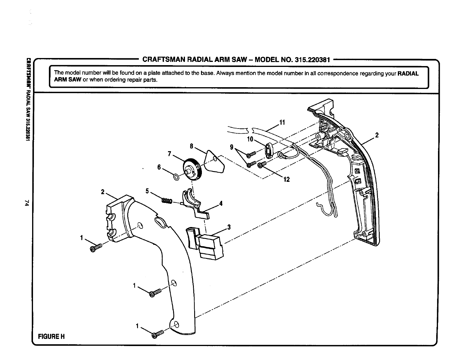
iCRAFTSMAN RADIAL ARM SAW- MODEL NO. 315.220381
I The model number will be found on a plate attached to the base. Always mentionthe model number inall correspondence regarding your RADIAL |
ARM SAW or when ordering repair parts. I
1
FIGUREH
I
J/°
/
/
12
/
/
./
/
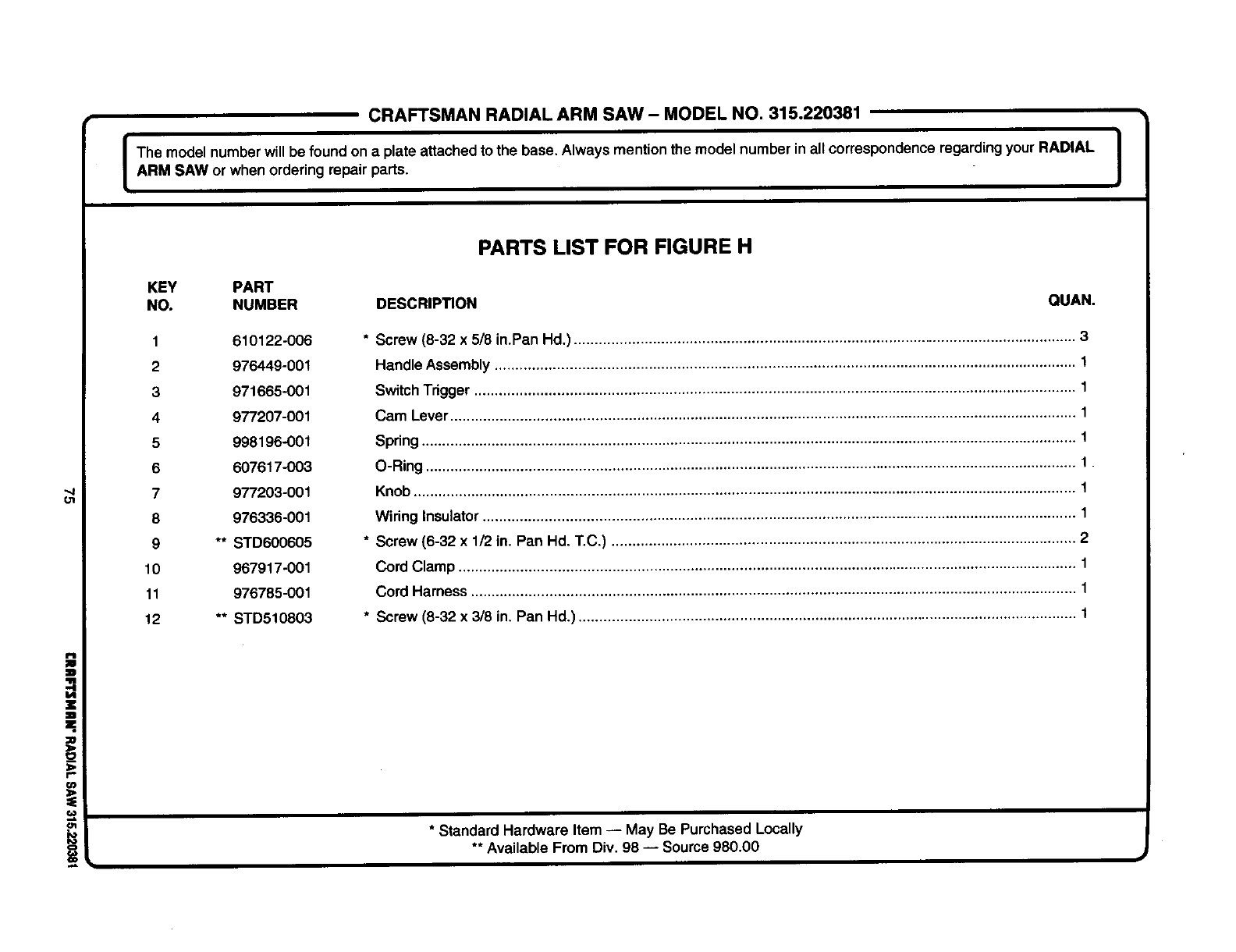
ot
X
z
m
=.
• CRAFTSMAN RADIAL ARM SAW- MODEL NO. 315.220381
The model numberwill be foundon a plate attachedto the base. Always mentionthe model number inall correspondenceregarding your RADIAL
ARM SAW or when ordering repair parts. J
PARTS LIST FOR FIGURE H
KEY PART
NO. NUMBER DESCRIP_ON OUAN.
1 610122-006
2 976449-001
3 971665-O01
4 977207-001
5 998196-001
6 607617-003
7 977203-001
8 976336-001
9 ** STD600605
10 967917-001
11 976785-001
12 ** STD510803
*Screw (8-32 x5/8 in.Pan Hd.) .......................................................................................................................... 3
Handle Assembly ............................................................................................................................................. t
SwitchTrigger .................................................................................................................................................. 1
Cam Lever........................................................................................................................................................ 1
Spring ............................................................................................................................................................... 1
O-Ring .............................................................................................................................................................. 1
Knob ................................................................................................................................................................. 1
Wiring Insulator................................................................................................................................................ 1
* Screw (6-32 x 1/2 in. Pan Hd. T.C.) ................................................................................................................. 2
Cord Clamp ...................................................................................................................................................... 1
Cord Harness ................................................................................................................................................... 1
* Screw (8-32 x 3/8 in. Pan Hd.) ......................................................................................................................... 1
•_ * Standard Hardware Item -- May Be Purchased Locally
•* Available From Div. 98 -- Source 980.00
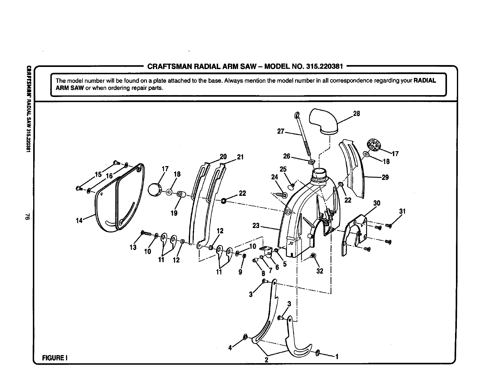
i
=.
:D
(n
--L
",4
CRAFTSMAN RADIAL ARM SAW - MODEL NO. 315.220381
IThe model number will be found on a plate attached to the base. Always mention the model number inall correspondenceregardingyour RADIAL |
I
ARM SAW or when ordering repair parts. I
17 25
18
19
30 31
13
11 9832
FIGUREI 2 1
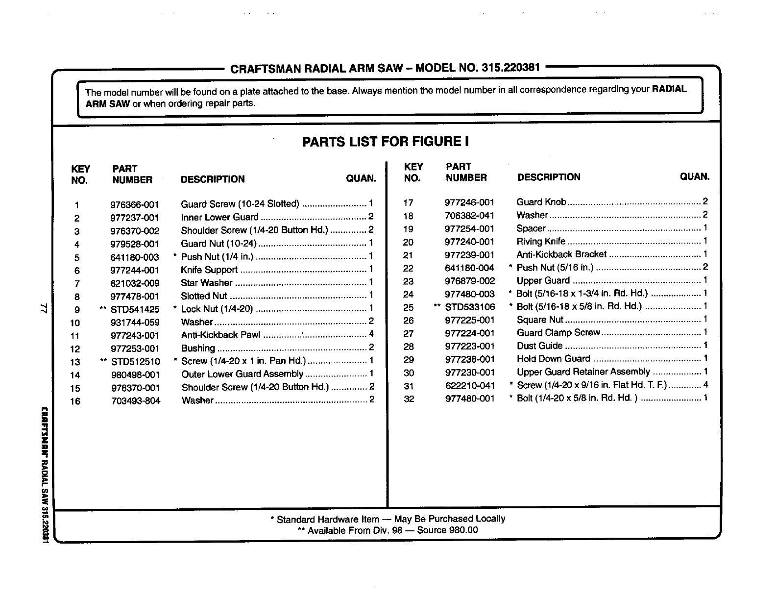
CRAFTSMANRADIAL ARM SAW- MODELNO. 315.220381
|
The model number will be found on a plate attached to the base. Always mentionthe model number in all correspondenceregarding your RADIAL |
ARM SAW or when ordering repair parts. J
i
(n
PARTS LIST FOR FIGURE I
KEY PART
NO. NUMBER DESCRIPTION QUAN.
1 976366-001
2 977237-001
3 976370-002
4 979528-001
5 641180-003
6 977244-001
7 621032-009
8 977478-001
9 ** STD541425
10 931744-059
11 977243-001
12 977253-001
13 ** STD512510
14 980498-001
15 976370-001
16 703493-804
Guard Screw (10-24 Slotted) ......................... 1
Inner Lower Guard ......................................... 2
Shoulder Screw (1/4-20 ButtonHd.) .............. 2
Guard Nut (10-24) .......................................... 1
* Push Nut (114in.) ........................................... 1
Knife Support ................................................. 1
Star Washer ................................................... 1
Slotted Nut ..................................................... 1
*LockNut (1/4-20) ........................................... 1
Washer ........................................................... 2
AnlJ-KickbackPawl ............... : ........................ 4
Bushing.......................................................... 2
* Screw (1/4-20 x 1 in. Pan Hd.) ....................... 1
Outer Lower Guard Assembly........................ 1
Shoulder Screw (1/4-20 ButtonHd.) .............. 2
Washer ........................................................... 2
KEY PART
NO. NUMBER DESCRIP_ON QUAN.
17 977246-001
18 706382-041
19 977254-001
20 977240-001
21 977239-001
22 641180-004
23 976879-002
24 977480-003
25 ** STD533106
26 977225-001
27 977224-001
28 977223-001
29 977238-001
30 977230-001
31 622210-041
32 977480-001
* Standard Hardware Item -- May Be Purchased Locally
** Available From Div. 98 -- Source 980.00
Guard Knob.................................................... 2
Washer ........................................................... 2
Spacer............................................................ 1
RivingKnife .................................................... 1
Anti-KickbackBracket .................................... 1
* Push Nut (5/16 in.) ......................................... 2
Upper Guard .................................................. 1
* Bolt(5/16-18 x 1-3/4 in. Rd. Hd.) .................... 1
* Bolt (5/16-18 x 5/8 in. Rd. Hd.) ...................... 1
Square Nut..................................................... 1
Guard Clamp Screw ....................................... 1
Dust Guide ..................................................... 1
Hold Down Guard .......................................... 1
Upper Guard Retainer Assembly ................... 1
* Screw (1/4-20 x 9/16 in. Flat Hd. 1".F.)............. 4
* Bolt (1/4-20 x 5/8 in. Rd. Hd. ) ........................ 1
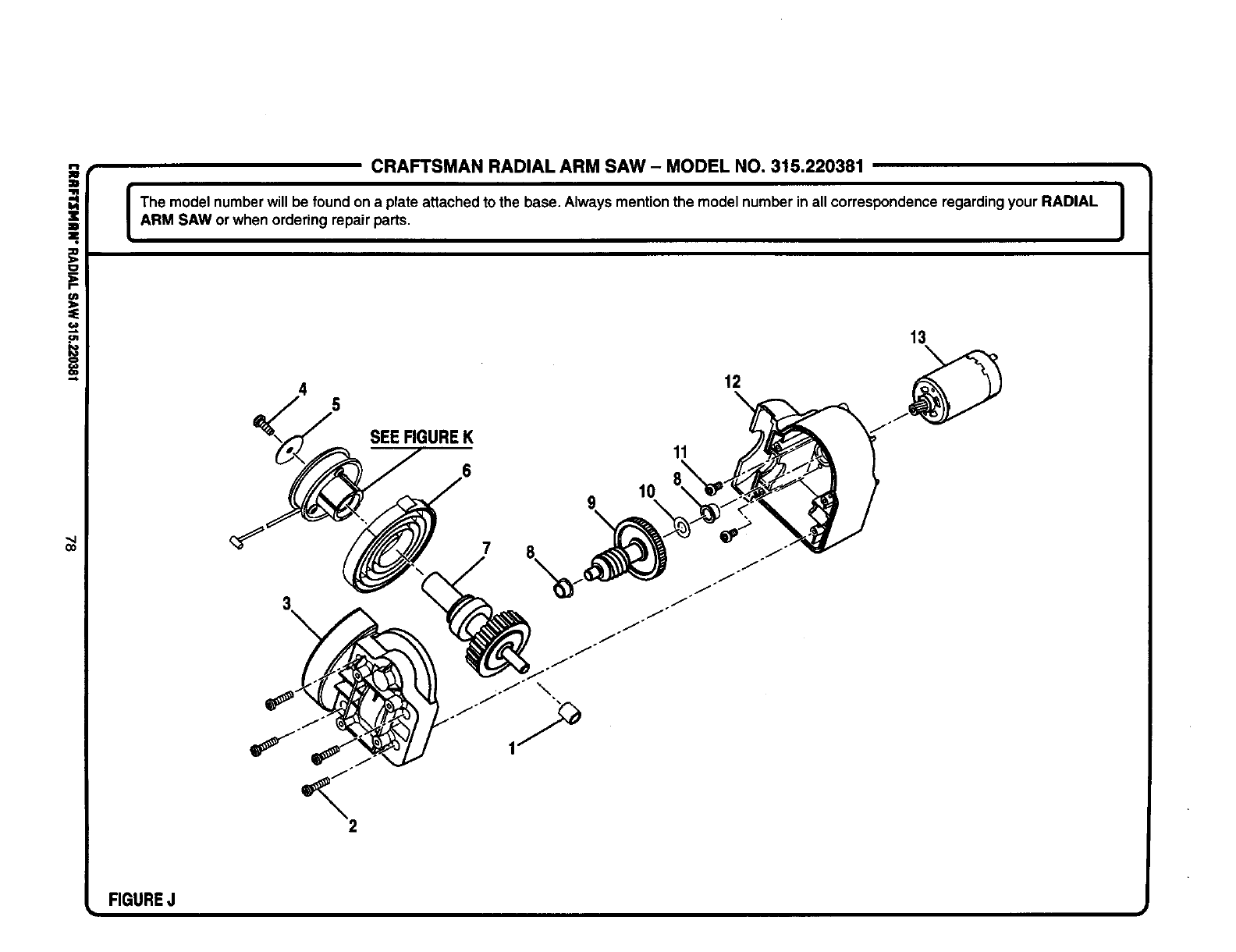
CRAFTSMAN RADIAL ARM SAW - MODEL NO. 315.220381
The model number will be foundon a plate attached to the base. Always mentionthe model number in all correspondenceregarding your RADIAL |
I
ARM SAW or when ordering repair parts. J
5
<2
SEEFIGUREK
9
11
10
12
j_
J
13
FIGUREJ
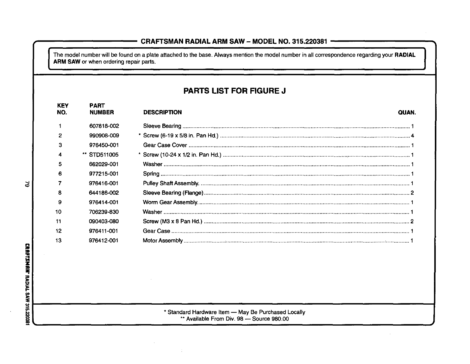
CRAFTSMANRADIAL ARM SAW- MODELNO. 315,220381
I The model number will be found on a plate attached to the base. Always mentionthe model number in all correspondenceregarding your RADIAL I
I
ARM SAW or when ordering repair parts. J
i
f-
PARTS LIST FOR FIGURE J
KEY PART
NO. NUMBER DESCRIP_ON QUAN.
1 607818-002
2 990908-009
3 976450-001
4** STD511005
8 662029-001
6 977215-001
7 976416-001
8 644186-002
9 976414-001
10 706239-830
11 090403-080
12 976411-001
13 976412-001
Sleeve Bearing .................................................................................................................................................. 1
* Screw (6-19 x 5/8 in. Pan Hd.) .......................................................................................................................... 4
Gear Case Cover .............................................................................................................................................. 1
* Screw (10-24 x 1/2 in. Pan Hd.) ........................................................................................................................ 1
Washer .............................................................................................................................................................. 1
Spring ................................................................................................................................................................ 1
Pulley Shaft Assembly....................................................................................................................................... 1
Sleeve Bearing (Flange).................................................................................................................................... 2
Worm Gear Assembly........................................................................................................................................ 1
Washer .............................................................................................................................................................. 1
Screw (M3 x 8 Pan Hd.) .................................................................................................................................... 2
Gear Case ......................................................................................................................................................... 1
MotorAssembly.................................................................................................................................................. 1
* Standard Hardware Item -- May Be Purchased Locally
** Available From Div. 98 -- Source 980.00
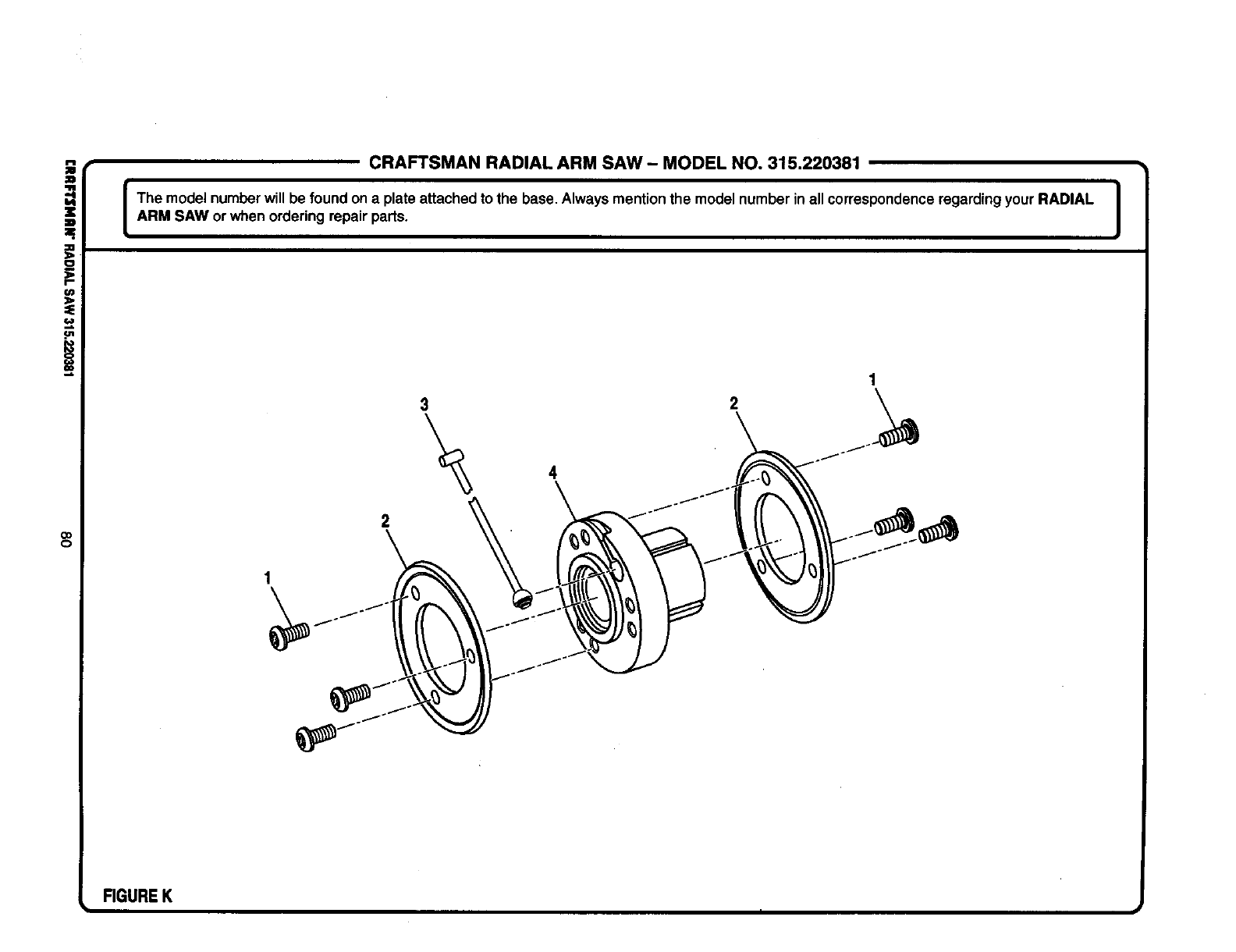
co
CRAFTSMAN RADIAL ARM SAW- MODEL NO. 315.220381
The model numberwill be found ona plate attached to the base. Always mentionthe model number in all correspondenceregardingyour RADIAL |
i
ARM SAW or when ordering repair parts. J
FIGUREK
t i I
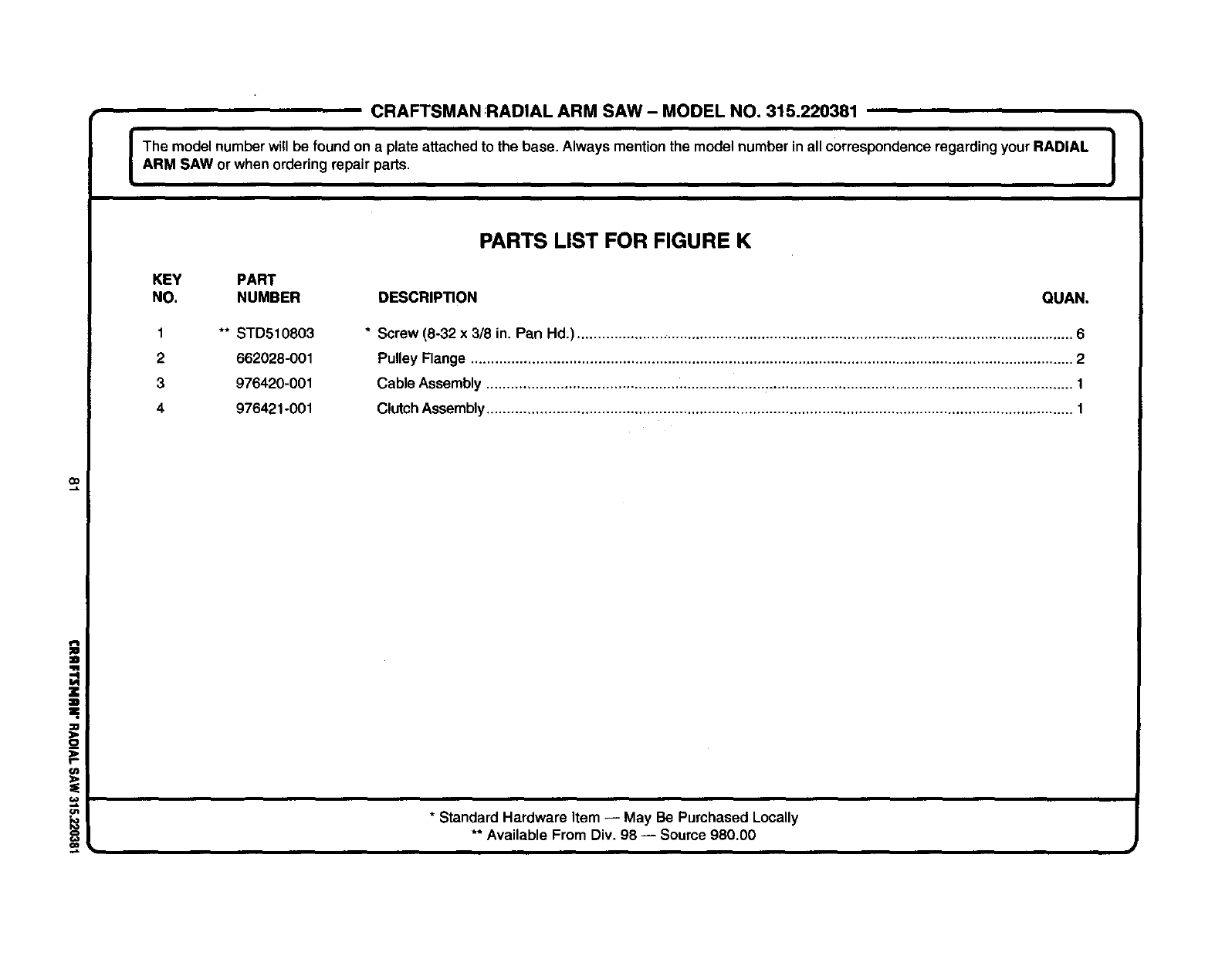
CRAFTSMAN RADIAL ARM SAW - MODEL NO. 315.220381
IThe model numberwill be found on a plate attachedto the base. Always mentionthe model number inall correspondenceregarding your RADIAL I
ARM SAW or when ordering repair parts. I
PARTS LIST FOR FIGURE K
KEY PART
NO. NUMBER DESCRIP_ON QUAN.
** STD510803
662028-001
976420-001
976421o001
1
2
3
4
*Screw (8-32 x3/8 in. Pan Hd.) .......................................................................................................................... 6
Pulley Flange .................................................................................................................................................... 2
Cable Assembly ................................................................................................................................................ 1
ClutchAssembly................................................................................................................................................ 1
O0
J
-!
m_
r=.
ol
o
* Standard Hardware Item -- May Be Purchased Locally
** Available From Div. 98 -- Source 980.00

In U.S.A. or Canada
for in-home major brand repair service:
Call 24 hours a day, 7 days a week
1-800-4-MY-HOME "(1-800-469-4663)
Para pedir servicio de reparacibn a domicilio - 1-800-676-5811
Au Canada pour tout le service ou les pieces - 1-800-469 4663
For the repair or replacement parts you need:
Call 6 a.m. - 11 p.m. CST, 7 days a week
Parts Directs,
1-800-366-PART (1-800-366-7278)
Para ordenar piezas con entrega a domicilio - 1-800-659-7084
For the location of a Sears Service Center in your area:
Call 24 hours a day, 7 days a week
1-800-488-1222
To purchase or inquire about a Sears Maintenance Agreement:
Call 7 a.m. - 5 p.m. CST, Monday - Saturday
1-800-827-6655
