Craftsman 315 22831 Users Manual
CRAFTSMAN Saw Table Manual L9080011 CRAFTSMAN Saw Table Owner's Manual, CRAFTSMAN Saw Table installation guides
315228311 62ca2af1-9399-4367-8aba-28783293c230 Craftsman Saw 315.22831 User Guide |
2015-01-05
: Craftsman Craftsman-315-22831-Users-Manual-161095 craftsman-315-22831-users-manual-161095 craftsman pdf
Open the PDF directly: View PDF ![]() .
.
Page Count: 64
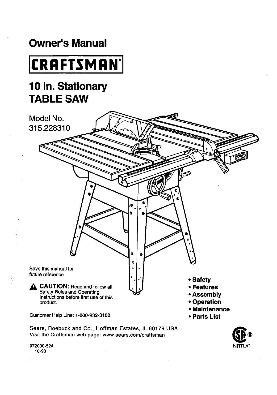
Owner's Manual
10 in. Stationary
TABLE SAW
Model No.
315.228310
Save this manual for
future reference
_, CAUTION: Read and follow all
Safety Rules and Operating
Instructions before first use of this
product.
".I
Customer Help Line: 1-800-932-3188
Sears, Roebuck and Co., Hoffman Estates, IL 60179 USA
Visit the Craftsman web page: www.sears.com/craftsman
972000-524
10-98
• Safety
•Features
•Assembly
•Operation
•Maintenance
• Parts List
NRTL/C
FULLONEYEARWARRANTYONCRAFTSMANTABLESAW
IfthisrRRFTSMRN Table Saw failsdue to a defect in material or workmanshipwithinone year fromthe date of
purchase. Sears will repair it, free of charge,
Contact a Sears Service Center for repair.
If this productis used forcommercialor rental purposes,this warranty appliesonly for 90 days fromthe date of
purchase.
This warranty gives you specificlegal dghts,and you may also have other rightswhich vary from state to state.
Sears, Roebuck and Co., Dept. 81"IWA, Hoffman Estates, IL 60179
Your saw has many features for making cuttingoperationsmore pleasant and enjoyable. Safety, performance
and dependabilityhave been given top priorityinthe design of thissaw making it easy to maintainand operate.
_, CAUTION: Carefully read throughthis entire owner's manual before usingyour new saw. Pay close
attentionto the Rules For Safe Operation and all Safety Alert Symbols,includingDanger, Wam ng and
Caution. If you use your saw properlyand only for what it is intended,you will enjoy years of safe, reliable
service.
._ Look for thissymbol to point outimportantsafety precautions.It means attention!!!Your safetyis involved.
WARNING:
The operationof any power tool can resultin foreign objects beingthrowninto your eyes,
which can result in severe eye damage. Before beginningpower tool operation, always
wear safety goggles or safety glasses with side shieldsand a full face shieldwhen needed.
We recommendaWide Vision Safety Mask for use over eyeglasses or standardsafety
glasses withside shields, available at Sears Retail Stores.
•Warranty and Introduction.............................................................................................................................. 2
•Table Of Contents ....................................................................................................................................... 2-3
•Rules For Safe Operation ........................................................................................................................... 4-6
•Electrical......................................................................................................................................................... 7
•Glossary and ProductSpecifications............................................................................................................. 8
•Unpackingand Accessories........................................................................................................................... 9
•Loose Parts List...................................................................................................... ...................................... 10
•Small Parts List ....................................................................................................................................... 11-12
•Tools Needed ............................................................................................................................................... 13
•Labels ...................................................................................................................................................... 14-15
•Features .................................................................................................................................................. 16-17
•Assembly ................................................................................................................................................. 18-27
InstallingHandwheels on Table Saw Base .................................................................................................. 18
AssemblingLeg Stand ............................................................................................................................ 18-19
CRAFTSMAN"TABLESAW315.228310 2
MountingtheLegStandontheTableSawBase........................................................................................ 19
AssemblingTable Extensions...................................................................................................................... 20
AligningTable Extensions............................................................................................................................ 20
Installingthe Rear Rail ................................................................................................................................. 21
Installingthe Front Rail ................................................................................................................................ 22
AligningRip Fence and Front Rail ............................................................................................................... 23
Mountingthe Motor ...................................................................................................................................... 23
Installingthe Belt and Belt Guard ................................................................................................................ 24
Checkingthe Throat Plate ............................................................................................................................ 24
Installingthe Blade Guard ............................................................................................................................ 25
Aligningthe Riving Knife with the Blade ...................................................................................................... 26
Checking Rip Fence and Blade Alignment .................................................................................................. 27
•Adjustments............................................................................................................................................. 28-32
Replacingthe Blade ..................................................................................................................................... 28
Heeling (Paralleling) the Sawblade to Miter Gage Groove ........................................ t............................ 29-30
Setting the Bevel Stops and Indicator..................................................................................................... 30-31
Adjustingthe Miter Gage .............................................................................................................................. 31
Removing/Replacing the Throat Plate ....................................................................................................... 32
•BasicOperation/bf the Table Saw .......................................................................................................... 33-40
Causes of Kickback...................................................................................................................................... 33
AvoidingKickback ........................................................................................................................................ 33
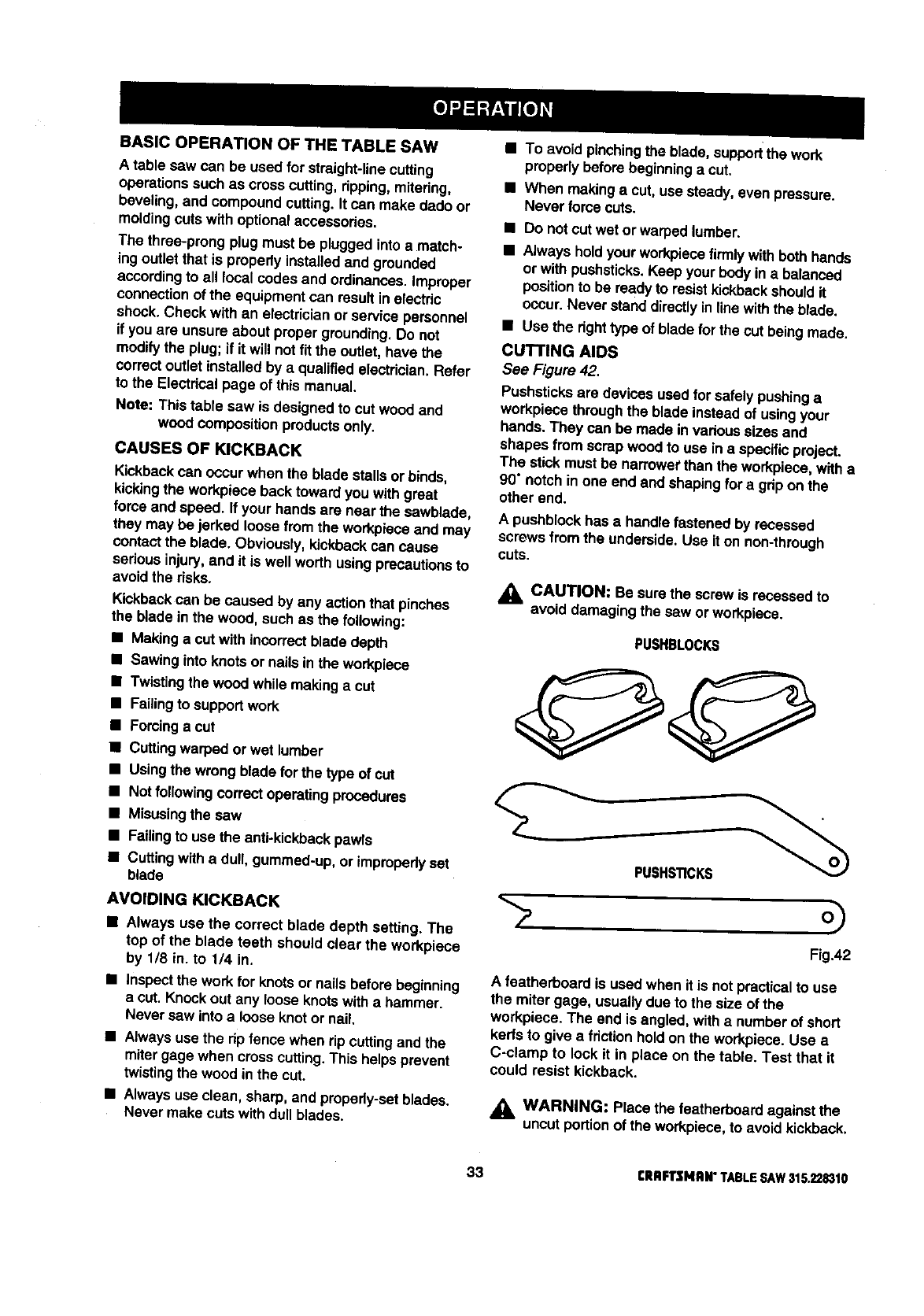
Making Cutting Aids ..................................................................................................................................... 33
Types of Cuts ............................................................................................................................................... 34
Making a Cross Cut ...................................................................................................................................... 35
Making a Rip Cut .......................................................................................................................................... 35
Making a Miter Cut ....................................................................................................................................... 36
Making a Bevel Cross Cut ............................................................................................................................ 36
Making a Bevel Rip Cut................................................................................................................................ 37
• Making a Compound (Bevel) Miter Cut ........................................................................................................ 38
Making a Large Panel Cut ............................................................................................................................ 39
Making a Non-Through Cut .......................................................................................................................... 39
Making a Dado Cut................................................. _..................................................................................... 40
•Maintenance ................................................................................................................................................. 41
•Lubrication.................................................................................................................................................... 41
•Troubleshooting....................................................................................................................................... 42-44
•Exploded View and Repair Parts List...................................................................................................... 46-63
•Parts Ordering /Service ................................................................................................................... back page
3 CRRFTSMIIN"TABLESAW315.228310
The purpose of safety symbols is to attract your attentionto possibledangers. The safety symbols,and the
explanationswiththem, deserve your careful attentionand understanding.The safetywarnings do not by
themselves eliminateany danger. The instructionsor warnings they give are not substitutesfor proper accident
preventionmeasures.
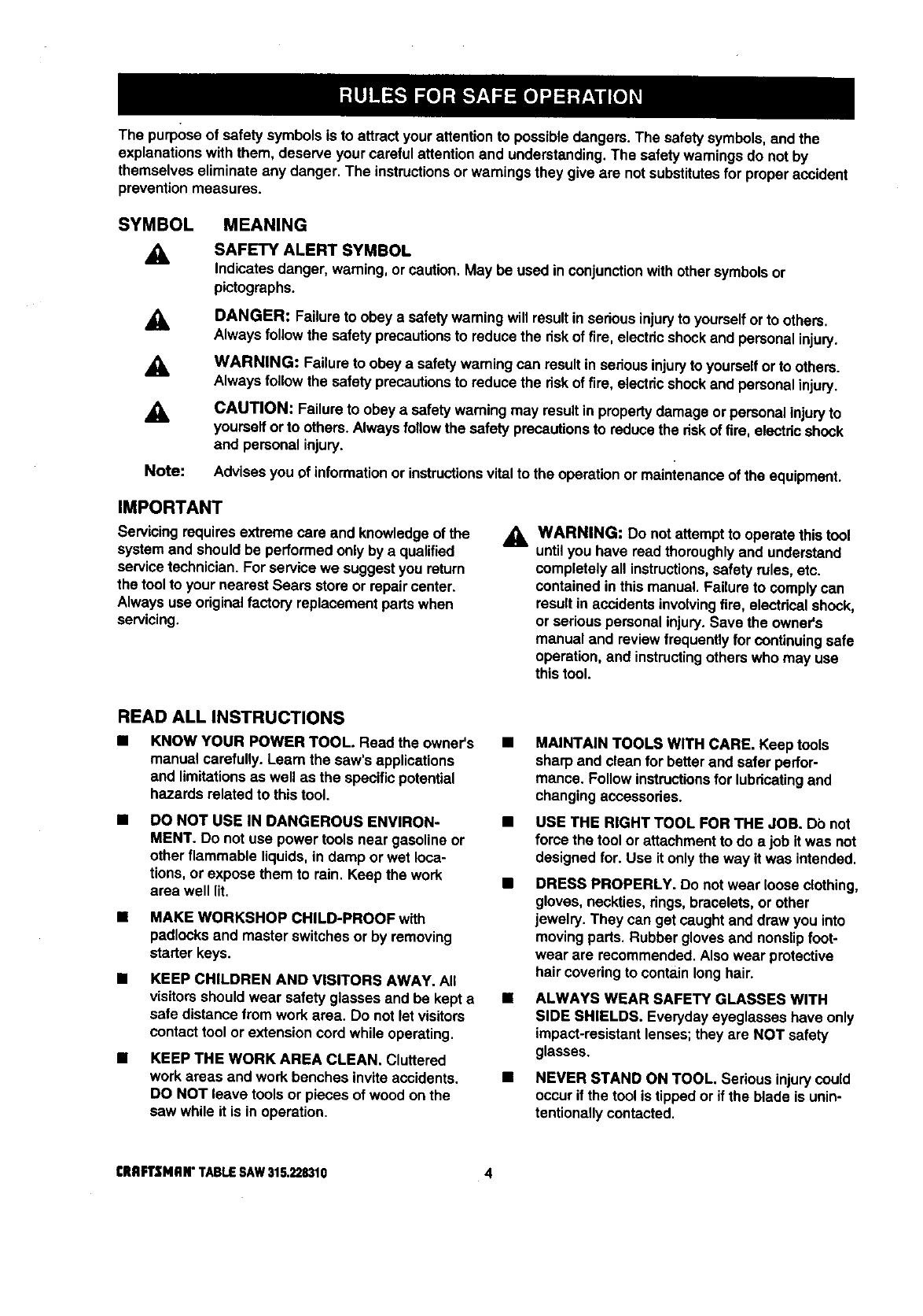
SYMBOL MEANING
A
A
A
Note:
SAFETY ALERT SYMBOL
Indicatesdanger, warning,or caution,May be used inconjunctionwithother symbolsor
pictographs.
DANGER: Failureto obey a safety warningwill resultin seriousinjuryto yourselforto others.
Alwaysfollow the safety precautionsto reduce the riskof fire, electdcshockand personalinjury.
WARNING: Failure to obeya safety warningcan result insedous injuryto yourselfor to others.
Always follow the safety precautionsto reduce the riskof fire, electdcshockand personal injury.
CAUTION: Failureto obey asafetywarning may resultin propertydamage or personalinjuryto
yourselfor to others.Alwaysfollowthe safety precautionsto reduce the riskof fire, electricshock
and personal injury.
Advisesyou of informationor instructionsvital tothe operationor mainienance of the equipment.
IMPORTANT
Servicing requiresextreme care and knowledgeof the
systemand shouldbe performed only by aqualified
servicetechnician.For servicewe suggestyou return
the toolto your nearest Sears store or repaircenter.
Always use originalfactory replacementpartswhen
servicing.
_1= WARNING: Do notattempt to operate thistool
untilyou have read thoroughlyand understand
completelyall instructions,safety rules, etc.
contained in this manual. Failure to comply can
resultin accidents involvingfire, electricalshock,
or seriouspersonal injury.Save the owner's
manual and reviewfrequently for continuingsafe
operation, and instructingothers who may use
this tool.
READ ALL INSTRUCTIONS
KNOW YOUR POWER TOOL. Read the owner's
manual carefully. Learn the saw's applications
and limitationsas well as the specificpotential
hazards related to thistool.
DO NOT USE IN DANGEROUS ENVIRON-
MENT. Do not use power tools near gasoline or
other flammable liquids,in damp or wet loca-
tions,or expose them to rain. Keep the work
area well lit.
•MAKE WORKSHOP CHILD-PROOF with
padlocksand master switches or by removing
starter keys.
•KEEP CHILDREN AND VISITORS AWAY. All
visitorsshould wear safety glasses and be kept a
safe distance from work area. Do not let visitors
contacttool or extensioncord while operating,
•KEEP THE WORK AREA CLEAN. Cluttered
work areas and work benches invite accidents,
DO NOT leave tools or pieces of wood on the
saw while it is in operation,
MAINTAIN TOOLS WITH CARE. Keep tools
sharp and clean for betterand safer perfor-
mance. Follow instructionsfor lubricatingand
changingaccessories.
USE THE RIGHT TOOL FOR THE JOB. Do not
force the tool or attachmentto do a job it was not
designed for. Use it only the way it was intended.
DRESS PROPERLY. Do notwear loose clothing,
gloves, neckties, rings, bracelets,or other
jewelry. They can get caught and draw you into
moving parts. Rubber gloves and nonslipfoot-
wear are recommended.Also wear protective
hair coveringto containlonghair.
ALWAYS WEAR SAFETY GLASSES WITH
SIDE SHIELDS. Everydayeyeglasses have only
impact-resistantlenses;they are NOT safety
glasses,
NEVER STAND ON TOOL. Seriousinjurycould
occur if the tool is tippedor if the blade is unin-
tentionallycontacted.
CRRFTSMRN"TABLESAW315.228310 4
BIULES FOR SAFE OPERATION (Continued)
BDO NOT OVERREACH. Keep proper footing and
balance at all times.
m
M
M
M
SECURE WORK. Use clamps or a vise to hold
workwhen practical. It's safer than usingyour
hand and frees both hands to operate tool.
USE THE PROPER EXTENSION CORD. Make
sure your extensioncord is in goodcondition.
Use only a cord heavy enough to carrythe
currentyour productwill draw. An undersized
cord will cause a drop in line voltage resultingin
lossof power and overheating. A wire gage size
(A.W.G.) of at least 14 is recommended for an
extensioncord 25 feet or less in length. If in
doubt, use the next heavier gage. The smaller
the gage number, the heavier the cord.
AVOID ACCIDENTAL STARTING. Be sure
switchis oft when pluggingin.
REMOVE WRENCHES AND ADJUSTING
KEYS. Get in the habit of checking-before
turningon tool - that hex I_eysand adjusting
wrenches are removed from tool.
M
M
M
M
M
CHECK DAMAGED PARTS. Before usingthe
tool again, check any damaged parts, including
guards, for proper operationand performance.
Check alignment of movingpads, bindingof
movingpads, breakage of pads, saw stability,
mountingand any other conditionsthat may
affect itsoperation. A damaged part must be
propedy repaired or replaced by a qualified
servicetechnician at a Sears store or repair
center to avoid riskof personal injury.
USE ONLY CORRECT BLADES. Use the right
blade size, style and cutting speed for the
material and the type of cut. Blade teeth should
point down toward the front of the table.
USE RECOMMENDED ACCESSORIES, Using
improperaccessoriesmay riskinjury.
USE ONLY SEARS REPLACEMENT PARTS,
All repairs, whether electdcalor mechanical,
should be made by a qualifiedservice technician
at a Sears storeor repaircenter.
KEEP GUARDS IN PLACE and in good working
order. This includesthe blade guard, rivingknife,
and anti-kickbackpawls.
CHECK DIRECTION OF FEED. Feed work into
ablade or cutteragainst the directionof rotation
of the blade or cutter only,
DISCONNECT ALL TOOLS. When notin use,
before servicing,or when changingattachments,
blades, bits, cutters, etc., all tools shouldbe
disconnectedfrom power supply.
M
M
DO NOT FORCE THE TOOL. It will do tbe job
better and more safely at the rate for which it
was designed.
NEVER LEAVE TOOL RUNNING UNAT-
TENDED. TURN THE POWER OFF. Do not
leave tool untilit comes to a complete stop.
BEFORE MOUNTING, DISCONNECTING OR
REMOUNTING THE MOTOR; unplugthe saw
and removethe switchkey.
AWARNING: When servicing,use only identical
Craftsman replacementpads. Use of any other
parts may create a hazard or cause product
damage.
M
M
M
M
M
M
M
M
M
NEVER USE THIS TOOL IN AN EXPLOSIVE
ATMOSPHERE. Normal sparkingof the motor
could ignitefumes.
MAKE SURE THE WORK AREA HAS AMPLE
LIGHTING to see the work and that no obstruc-
tions will interferewithsafe operation BEFORE
performingany work usingthistool.
DO NOT USE TOOL IF SWITCH DOES NOT
TURN IT ON AND OFF. Have defective switches
replaced by aqualifiedservicetechnician at a
Sears store or repaircenter.
GUARD AGAINST ELECTRICAL SHOCK by
preventingbodycontactwith grounded surfaces
such as pipes, radiators,ranges, refrigerator
enclosures.
GROUND ALL TOOLS. See Electricalpage.
WEAR A DUST MASK to keep from inhalingfine
particles.
PROTECT YOUR HEARING. Wear hearing
protectiondudng extended periodsof operation.
DO NOT OPERATE THIS TOOL WHILE UN-
DER THE INFLUENCE OF DRUGS, ALCOHOL,
OR ANY MEDICATION.
STAY ALERT AND EXERCISE CONTROL,
Watch what you are doing and use common
sense, Do not operate tool when you ere tired.
Do not rush.
AVOID AWKWARD OPERATIONS AND HAND
POSITIONS where a sudden slip couldcause
your hand to move into the blade. ALWAYS
make sure you have good balance,
ALWAYS SUPPORT LARGE WORK PIECES
while cuttingto minimize riskof blade pinching
and kickback. Saw may slip,walk or slide while
cuttinglarge or heavy boards.
5 CRAFTSMAN"TABLESAW315,228310
RULES FOR SAFE OPERATION (Continued)
•GUARD AGAINST KICKBACK. Kickbackcan
occurwhen the blade sta$$s,ddving the work
piece back toward the operator. It can pullyour
hand intothe blade, resultingin sedous personal
injury.Stay out of the blade path and turn switch
off immediatelyif blade bindsor stalls.
USE A SUPPORT FOR THE SIDES AND BACK
OF THE SAW TABLE when sawing wide or long
workpieces. Use a sturdy"outrigger" support if a
table extensionis morethan 24 inches long and
is attached to the saw, to preventtipping.
CUT ONLY WOOD, PLASTIC OR WOOD-LIKE
MATERIALS. Do not cut metal.
•NEVER cut more than one piece at a time. DO
NOT STACK more than one workpieceon the
saw table at a time.
DO NOT REMOVE THE SAW'S BLADE
GUARDS. Never operate the saw with any guard
or cover removed. Make sure all guardsare
operating propedy befol'eeach use.
NEVER PERFORM ANY OPERATION FREE-
HAND. Always place the workpieceto be cut on
the saw table and position it firmly against the
fence as a backstop.
USE THE RIP FENCE. Always use a fence or
straightedge guide when ripping.
BEFORE MAKING A CUT, be sure all adjust-
ments are secure.
•BE SURE THE BLADE PATH IS FREE OF
NAILS. Inspect for and remove all nails from
lumber before cutting.
•BE SURE THE BLADE CLEARS THE
WORKPIECE. Never start the saw with the blade
touchingthe workplace.
•KEEP HANDS AWAY FROM CUTTING AREA.
Do notreach underneathworkor in blade cutting
path withyour hands and fingersfor any reason.
Alwaysturn the power off.
•USE A PUSHBLOCK OR PUSH STICK for
workpiecesso small that your fingersgo under
the blade guam:d.NEVER TOUCH BLADE or
other movingpartsduringuse, for any reason.
_k WARNING: Blade coasts after beingtumed off.
ALLOW THE MOTOR TO COME UP TO FULL
SPEED before startinge cut to avoid blade
binding or stalling.
ALWAYS PUSH THE WORKP|ECE; never pullit
toward the saw.
DO NOT FEED THE MATERIAL TOO QUICKLY.
Do notfome the workpieceagainst the blade.
ALWAYS TURN OFF SAW before disconnecting
it,to avoid accidental startingwhen reconnecting
to power supply. NEVER leave the table saw
unattended while connectedto a power source.
BEFORE CHANGING THE SETUP, REMOVING
COVERS, GUARDS, OR BLADE; unplugthe
saw and remove the switchkey.
KEEP TOOL DRY, CLEAN, AND FREE FROM
OIL AND GREASE. Alwaysuse a clean cloth
when cleaning. Never use brake fluids, gasoline,
petroleum-based products,or any solvents to
clean tool.
KEEP BLADES CLEAN, SHARP AND WITH
SUFFICIENT SET. Sharp blades minimize
stalling and kickback.
USE ONLY OUTDOOR EXTENSION CORDS.
Use only extensioncords withthe marking
=Acceptable for use with outdoorappliances;
store cords indoorswhile not in use." Use
extensioncords with an electricalratingnot less
than the saw's rating.Always disconnectthe
extensioncord from the outlet before disconnect-
ingthe productfrom the extensioncord.
•INSPECT TOOL CORDS AND EXTENSION
CORDS PERIODICALLY and, if damaged, have
repaired by a qualifiedsewice technicianat a
Sears store or repaircenter. Stay constantly
aware of cord locationand keep it well away
fromthe movingblade.
•DO NOT ABUSE CORD, Never yank cord to
disconnectit from receptacle. Keep cord from
heat, oil,and sharp edges.
SAVE THESE INSTRUCTIONS. Referto them
frequently and use to instructother users. If you
loan someone this tool, loan them these instruc-
tions also.
SAVE THESE INSTRUCTIONS
[RAFTSMRW TABLESAW316,228310 6
EXTENSION CORDS
Use only 3-wire extensioncords that have 3-prong
groundingplugsand 3-pole receptaclesthat accept
the tool's plug. When usinga power tool at a consid-
erable distance fromthe power source, use an
extensioncord heavy enough to carrythe current that
the tool will draw. An undersized extensioncord will
cause a drop in line voltage, resultingin a loss of
power and causingthe motorto overheat. Use the
chart providedbelow to determinethe minimumwire
size requiredin an extensioncord. Only roundjack-
eted cords listed by Underwriter'sLaboratories(UL)
shouldbe used.
Length of Extension Cord Wire Size (A.W.G.)
Up to 25 feet 14
26-100 feet 12
When workingwith the tool outdoors,use an exten-
sion cord that is designed for outsideuse. This is
indicated by the lettersWA on the cord's jacket.
Before using an extensioncord, inspect it for loose or
exposed wires and cut or worn insulation.
_k CAUTION: Keep the cord away from the cutting
area and positionthe cord so that it will not be
caught on lumber, tools,or other objects dudng
cuttingoperations.
ELECTRICAL CONNECTION
Your Sears Craftsman Table Saw is powered by a
precisionbuiltelectric motor. It should be connected
to a power supply that Is 120 volts, 60 Hz, AC only
(normal household current). Do not operate thistool
ondirect current (DC). A substantialvoltage drop will
cause a lossof power and the motor will overheat. If
the saw does not operate when plugged intoan
outlet,double check the power supply.
SPEED AND WIRING
The no-load speed of your table saw is approximately
3,600 rpm. This speed is not constantand decreases
undera load or with lowervoltage. For voltage, the
wiring in a shop is as importantas the motor's horse-
power rating. A line intended only for lightscannot
properlycarry a power tool motor. Wire that is heavy
enough for a short distance will be too lightfor a
greater distance. A line that can supportone power
tool may not be able to supporttwo or three tools.
GROUNDING INSTRUCTIONS
In the event of a malfunctionor breakdown, grounding
providesa path of least resistancefor electriccurrent
to reduce the riskof electric shock. This tool is
equippedwith an electric cord having an equipment-
groundingconductorand a groundingplug. The plug
must be pluggedinto a matchingoutletthat is propedy
installedand grounded in accordancewith all local
codes and ordinances.
Do not modifythe plug provided. If it will not fit the
outlet,have the proper outlet installedby a qualified
electrician.Improperconnectionof the equipment-
groundingconductorcan result in a riskof electric
shook.The conductorwith insulationhaving an outer
surfacethat is green withor withoutyellowstripes is
the equipment-groundingconductor. If repairor
replacementof the electdc cord or plug is necessary,
do not connect the equipment-groundingconductorto
aliveterminal.
Check witha qualifiedelectricianor service personnel
if the groundinginstructionsare notcompletely
understood,or if indoubt as to whether the tool is
properlygrounded.
Repair or replace a damaged or worn cord immedi-
ately.
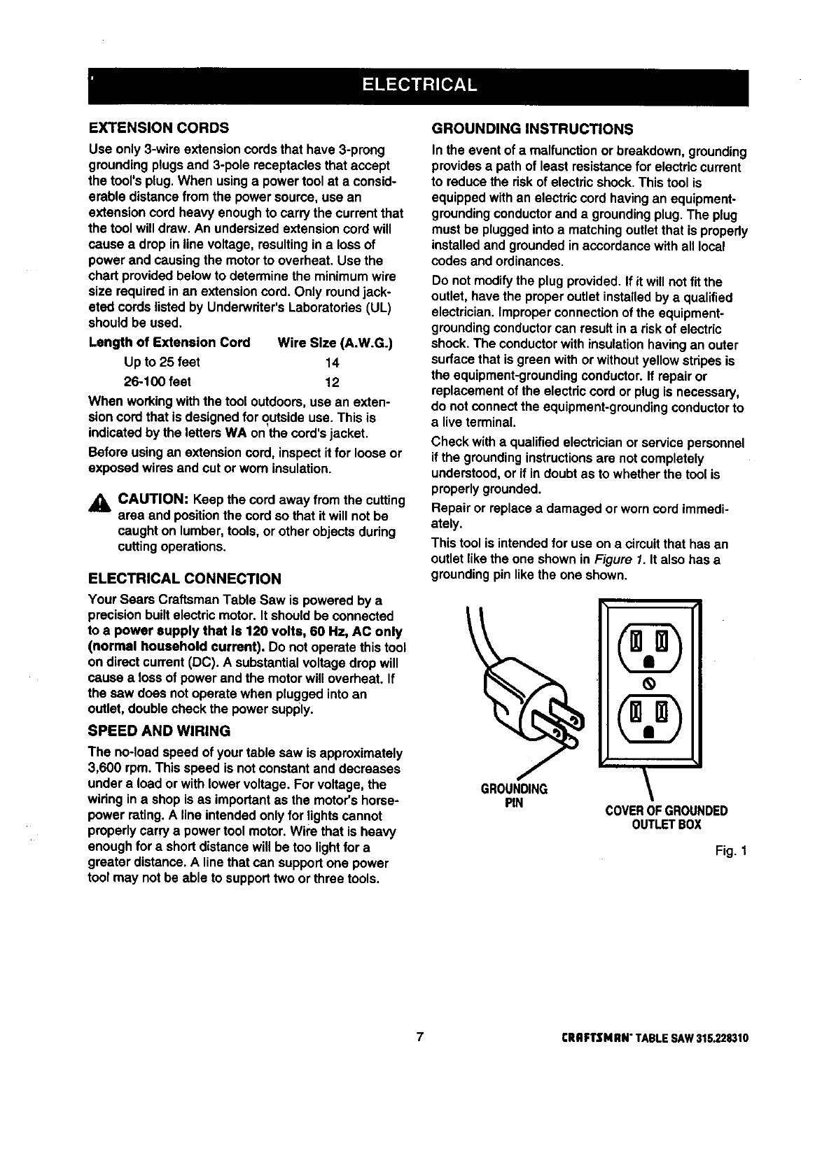
This tool is intendedfor use on a circuitthat has an
outlet likethe one shown in Figure 1. It also has a
groundingpin like the one shown.
GROUNDING
PIN COVEROFGROUNDED
0UTLETBOX
Fig. 1
7rRRFTSNRN"TABLESAW31S.228310

Anti-Kickback Pawls
Toothed safety devicesbehind the blade designed to
stop a workpiece from beingkicked back at the
operator duringa rippingoperation.
Arbor
The shaft on which a blade or cuttingtool is mounted.
Bevel Cut
A cuttingoperationmade withthe blade at any angle
other than 90" to the saw table.
Compound Cut
A cut with both amiterangle and abevel angle.
Crosscut
A cuttingoperation made acrossthe grain or the width
of the workpiece.
Dsdo
Anon-throughcut that gives a square notch ortrough;
requires a special blade.
Featherboard
A device to help guide workpiecesduring ripcuts.
Freehand (for table saw)
Dangerous practice of making s cut withoutusingdp
or miterfences. See Safety Rules.
Gum
A sticky, sap-based residuefromwood products.
Heel
Alignmentof the blade.
Kerf
The material removed by the blade in a through cut or
the slotproducedby the blade in a non-throughcut.
Kickback
A hazard that can occur when blade bindsor stalls,
throwingworkpiece back toward operator.
Leading End
The end of the workpiecepushed into the cuttingtool
first.
Miter Cut
A cuttingoperationmade with the miter gage at any
angle other than 0".
Molding
Anon-throughcut that givesa varied shape to the
workpiece and requires e special blade.
Push Stick
A device usedto feed the workpiecethroughthe saw
blade duringnarrowcuttingoperations. It helps keep
the operator'shands well away from the blade,
Rabbet
Anotch inthe edge of aworkpiece.
Resaw
A cuttingoperationto reduce the thicknessof the
workpieceinorder to make thinner pieces.
Resin
A sticky,sap-based substance.
RIp Cut
A cut made withthe the grainof the workpiece.
Sswblade Path
The area directlyin line withthe blade -- over, under,
behind, orin front of it. Also, the workpiecearea
which willbe or has been cut by the blade.
Set
The distancethat the tip of the saw blade tooth is bent
(or set) outwardfrom the face of the blade.
Throw-Back
Saw throwingback a workpiece;similarto kickback,
Through Sawing
Any cuttingoperationwhere the blade extends
completelythroughthe workpiece.
Trailing End
The workpieceend last cut by the blade in a dp cut.
Workp|ece
The item on whichthe cutting operationis beingdone.
The surfacesof a workpieceare commonlyreferredto
as faces, ends, and edges.
Worktable
The surfaceon which the wodq_ece rests while
performinga cuttingoperation.
Blade Arbor 5/8 in.
Blade Diameter 10 in.
Blade Tilt 0" - 45"
Table Size withouttable extensions 20 in. x 27 in.
Table Size with table extensions 44 in. x 27 in.
Rating 120 V, 60 Hz - AC only
Input 13 Amperes
No Load Speed 3,600 RPM
Cutting Capacity withMiter at 0"/Bevel 0": 3-3/8 in.
Cutting Capacity withMiter at O'/Bevel45": 2-1/4 in.
rRRFTSNlUI" TABLESAW$1G,228310 8
Your new table saw has been designed to give you
many years of high qualityperformance.To insure
thisgoal, proper care and treatment is important.
Careful treatment beginswith removing all pads from
the cartonand checkingthem against the listof loose
parts.The long box containsthe rails. The large box
holdsall other parts, which are detailed inthe Loose
Parts List.
• Separate the saw and all partsfrom the packing
materials and check each against the packing list,
especiallythe small partsthat can be hidden inthe
packingmaterial
Note: Do notdiscard the packingmaterials untilyou
have carefullyinspectedthe saw, identifiedall
parts, and satisfactorily operated your new saw.
_IL WARNING: Never use gasoline, naptha, or
other highlyvolatile solvents.Do not ever let
brake fluids, gasoline,petroleum-based
products,or penetratingoilscontact plasticparts.
Such chemicals can weaken or destroy plastic.
II Remove the wax paper covering on the table. Use
any ordinary household type grease and spot
remover. Immediatelyapply a coat of automotive
type paste wax to the table and table exensions.
,_ WARNING: To prevent accidental startingthat
couldcause possibleseriouspersonal injury,
assemble all partsto your saw before connecting
it to power supply.Saw should never be
connected to power supplywhen you are
assembling parts, making adjustments, installing
or removingblades, or when notin use.
,_ WARNING: If any partsare missing,do not
operate thistool untilthe missingparts are
replaced. Failure to do so could result inpossible
seriouspersonal injury.
The following recommended accessoriesare currentlyavailable
•Fence Guide System
•Guide Master
•Box Joint & Miter Guide
• Universal Jig
• Taper Jig
• 10 in. Sanding Disc
• 8 in. Sanding Disc
• Elite Dado
•ExcaliburDado
• 7 in. Adj. Dado 36 tip
• 7 in. Adj. Dado 24 tip
at Sears Retail Stores.
•7 in. Stack Steel Dado
• 7 in. x 9/16 in. Stack Dado
•7 in. MoldingHead Set
•2 Bit MoldingHead Set
•Saw Baskets
•JointerClamps
•Specialty Throat Plate
•Miter Gage Hold Down Clamp
•Align-A-RipXRC Rip Fence
• Dust CollectionSystem
,_ WARNING: The use of attachmentsor accessories not listed might be hazardous.
9 [RAFTSMAN" TABLESAW315.228310
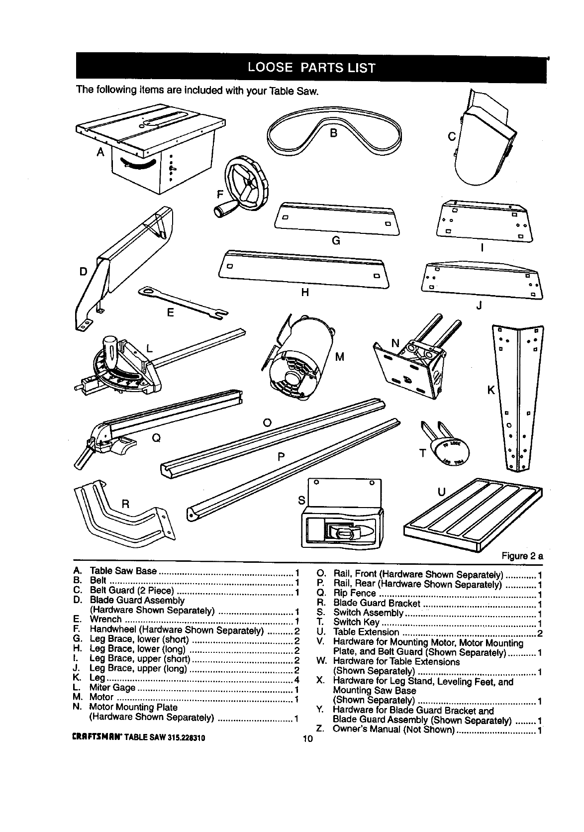
The following items are included with your Table Saw.
A
D
G
o
Q
I
J
Figure 2 a
A. Table Saw Base .................................................... 1
B. Belt ....................................................................... 1
C. Belt Guard (2 Piece) ............................................. 1
D. Blade Guard Assembly
(Hardware Shown Separately) ............................. 1
E. Wrench ................................................................. 1
F. Handwheel (Hardware Shown Separately) .......... 2
G. Leg Brace, lower (short) ....................................... 2
H. Leg Brace, lower(long) ........................................ 2
I. Leg Brace, upper(short)....................................... 2
J. Leg Brace, upper (long) ........................................ 2
K. Leg........................................................................ 4
L. Miter Gage ............................................................ 1
M. Motor .................................................................... 1
N. Motor MountingPlate
(Hardware Shown Separately) ............................. 1
tRRFTZMRI¢ TABLE SAW 315.228310
O. Rail, Front(Hardware Shown Separately)............ 1
P. Rail, Rear (Hardware Shown Separately) ............ 1
Q. Rip Fence ............................................................. 1
R. Blade Guard Bracket ......................... ;.................. 1
S. SwitchAssembly ......,, ......................................... 1
T. SwitchKey ............................................................ 1
U. Table Extension.................................................... 2
V. Hardware for MountingMotor, MotorMounting
Plate, and BeltGuard (Shown Separately) ........... 1
W. Hardware for Table Extensions
(Shown Separately) .............................................. 1
X. Hardware for Leg Stand, LevelingFeet, and
MountingSaw Base
(Shown Separately) .............................................. 1
Y. Hardware for Blade Guard Bracketand
Blade Guard Assembly (ShownSeparately) ........ 1
Z. Owner's Manual (Not Shown)............................... 1
10
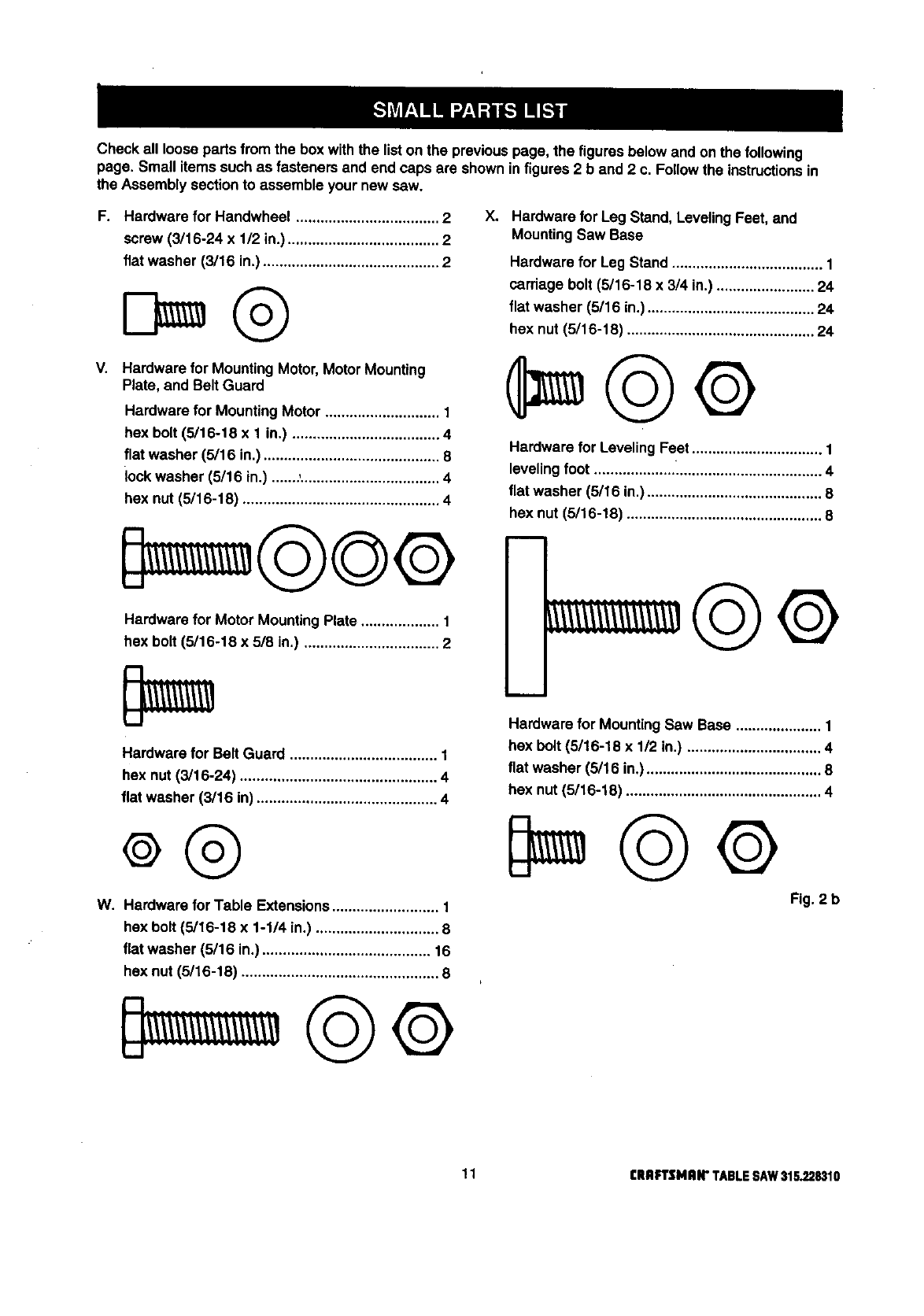
Checkallloosepartsfromtheboxwiththelistonthepreviouspage,thefiguresbelowandonthefollowing
page,Smallitemssuchasfastenersandendcapsareshowninfigures2band2c.Followtheinstructionsin
theAssemblysectiontoassembleyournewsaw.
F. Hardware for Handwheel ................................... 2
screw (3/16-24 x 1/2 in.)..................................... 2
flat washer (3/15 in.) ........................................... 2
V. Hardware for MountingMotor, MotorMounting
Plate, and Belt Guard
Hardware for Mounting Motor ............................ 1
hex bolt (5/16-18 x 1 in.) .................................... 4
flat washer (5/16 in.) ........................................... 8
lock washer (5/16 in.) .......,.................................. 4
hex nut (5/16-18) ................................................ 4
Hardware for Motor MountingPlate ................... 1
hex bolt (5/16-18 x 5/8 in.) ................................. 2
Xo Hardware for Leg Stand, LevelingFeet, and
MountingSaw Base
Hardware for Leg Stand ..................................... 1
carriage bolt (5/16-18 x 3/4 in.) ........................ 24
flat washer (5/16 in.)......................................... 24
hex nut(5/16-18) .............................................. 24
Hardware for Leveling Feet ................................ 1
leveling foot ........................................................ 4
flat washer (5/16 in.) ........................................... 8
hex nut (5/16-18) ................................................ 8
Hardware for Belt Guard .................................... 1
hex nut (3/16-24) ................................................ 4
flat washer (3/16 in) ............................................ 4
W. Hardware for Table Extensions.......................... 1
hex bolt (5/16-18 x 1-1/4 in.) .............................. 8
flat washer (5/16 in.) ......................................... 16
hex nut (5/16-18) ................................................ 8
m
Hardware for MountingSaw Base ..................... 1
hex belt (5116-18 x 1/2 in.) ................................. 4
flat washer (5/16 in°)........................................... 8
hex nut (5116-18) ................................................ 4
Fig. 2 b
11 [IIRFrSMRIr TABLESAW31S.228310
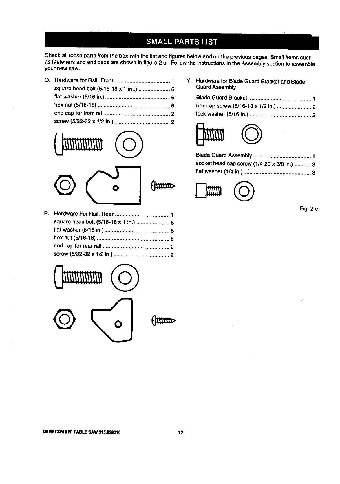
Check all loose partsfrom the box with the listand figuresbelowand on the previouspages, Small items such
as fasteners and end caps are shown in figure2 c. Follow the instructionsin the Assembly sectionto assemble
your new saw.
O. Hardware for Rail, Front..................................... 1
square head bolt (5/16-18 x 1 in..) ..................... 6
flat washer (5/16 in.) ........................................... 6
hex nut (5/16-18) ................................................ 6
end cap for front rail ........................................... 2
screw (5/32-32 x 1/2 in.) ..................................... 2
©
F, Hardware For Rail, Rear .................................... 1
square head bolt (5/16-18 x 1 in.) ...................... 6
flat washer (5/16 in.) ........................................... 6
hex nut (5/16-18) ................................................ 6
end cap for rear rail ............................................ 2
screw (5/32-32 x 1/2 in.) ..................................... 2
Y. Hardware for Blade Guard Bracketand Blade
Guard Assembly
Blade Guard Bracket.......................................... 1
hex cap screw (5/16-18 x 1/2 in.) ....................... 2
lock washer (5/16 in.) ......................................... 2
Blade Guard Assembly....................................... 1
socket head cap screw (1/4-20 x 3/8 in.) ........... 3
flat washer (1/4 in.) ..._......................................... 3
Fig. 2 c
CRAFTSMAN"TABLESAW315.228310 12
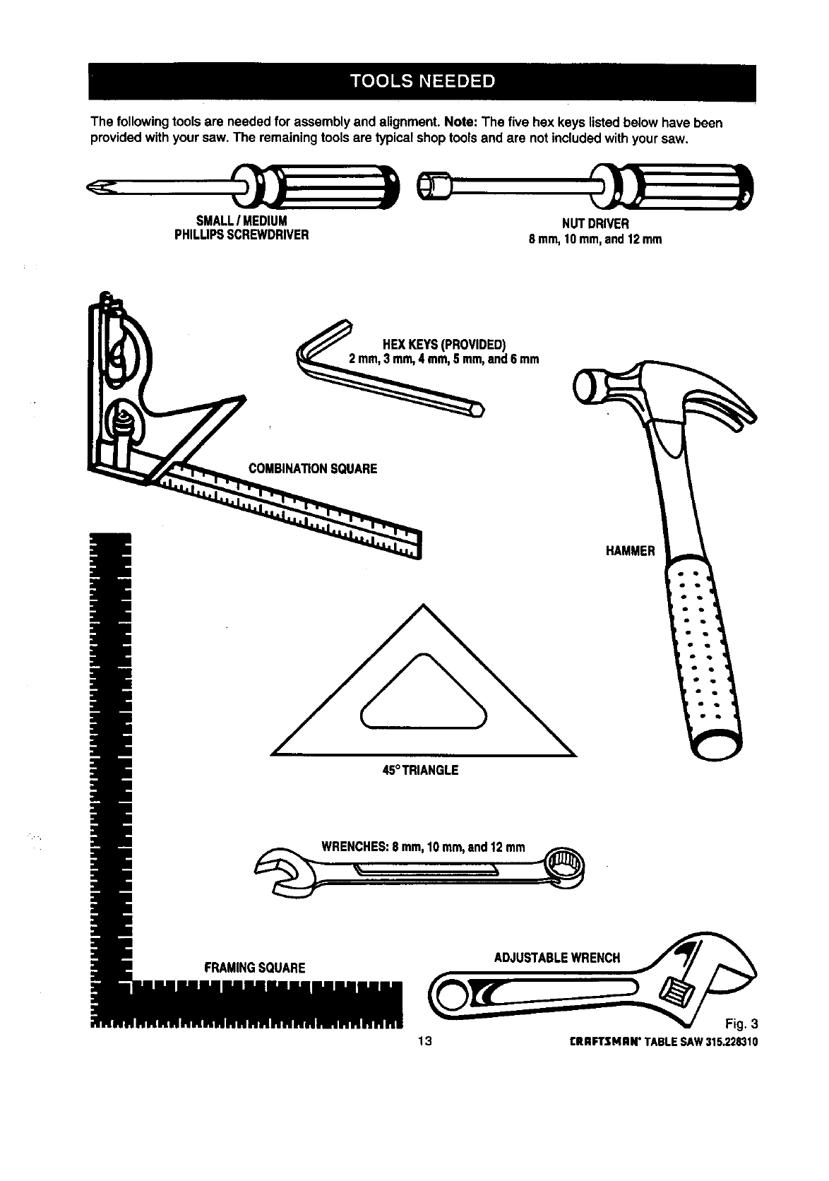
The followingtoolsare needed for assemblyand alignment. Note: The five hex keys listedbelow have been
providedwith your saw. The remainingtools are typicalshop toolsand are notincludedwithyour saw.
SMALLIMEDIUM
PHILUPSSCREWDRIVER NUTDRIVER
8 mm,10mm,and12mrn
HEXKEYS(PROVIDED)
and6 mm
COMBINA_ONSOUARE
HAMMER
45°TRIANGLE
WRENCHES:8 mm,10mm,and12mm
FRAMINGSQUARE ADJUSTABLEWRENCH
13 rRRFTSMRN"TABLESAW315.228310
/
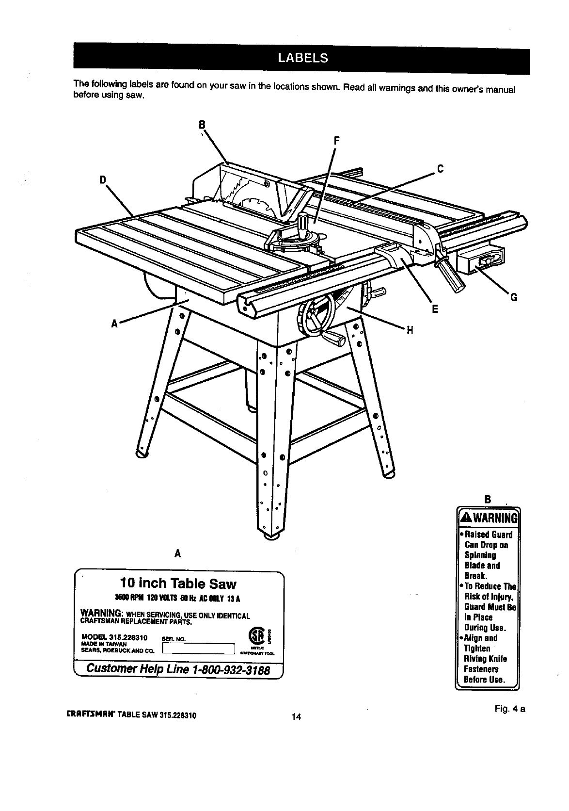
The followinglabels are found on your saw inthe locationsshown. Read allwarnings and thisowner's manual
before using saw,
B
D
e
o
o
A
10 inch Table Saw
36QOIh_M120VOLTS60HzACONLY13A
WARNING:WHEN SERVICING, USE ONLY IDENTICAL
CRAFTSMANREPLACEMENTPARTS.
MODEL 315.228310 S_R.NO. _i
MAD_ IN TAJWAN
SEARS, ROEBUCK AND CO. i I sr_l_4_ TOOL
•Customer Help Line 1-800-932-3188 ,
F
H
C
G
B
AWARNINI
• RaisedGuard
CanDropon
Spinning
Bladeand
Break.
•ToReduceThe
RiskofInjury,
GuardMust81
InPlace
DuringUse.
,Alignand
Tighten
RivingKnife
Fasteners
BeforeUse.
Fig, 4 a
CRAFTSMAN"TABLESAW315.228310 14
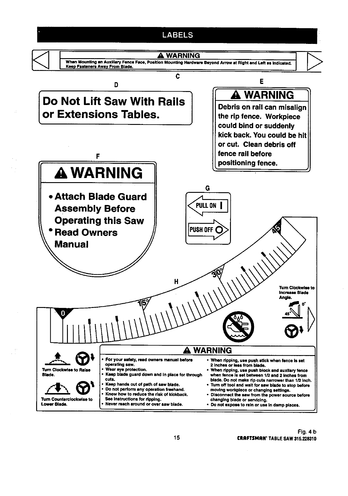
I_WARNING
When Mounting an Auxiliary Fence Face, Position Mounting Hardware Beyond Arrow at Bight and Left as Indicated.
Keep Fasteners Away From Blade.
C
D E
I ] ,A,WARNING
Do Not Lift Saw With Rails Debris on rail can misalign
Lor Extensions Tables. the rip fence. Workpiece
could bind or suddenly
F
A WARNING
• Attach Blade Guard
Assembly Before
Operating this Saw
•Read Owners
kick back. You could be hit
or cut. Clean debris off
fence rail before
positioning fence.
G
,_LLONI
PUSHOFF
H
®
A WARNING
Turn Clockwise to
Increase Blade
Angle.
Turn Clockwise to Raise
Blade.
"rumCounterclockwise to
Lower Blade.
• For your safety, read owners manual before
operating saw.
• Wear eye p_otection.
• Keep blade guard down and In place for through
cuts.
• Keep hands out of path of saw blade.
•Do not perform any operation freehand.
•Know how to reduce the risk of kickback.
See instructions for ripping.
•Never reach around o¢ over/Niw blade.
•When ripping, use push stick when fence is set
2 Inches or lees from blade.
•When ripping, use push block and auxllary fence
when fence Is set between 1/2 and 2 inches from
blade. Oo nut make rip cuts narrower than 1/2 Inch.
•Tum off tool and walt for saw blade to stop before
moving workplece or changing settings.
•Disconnect the saw from the power source before
changing blade or se_icing.
•Do not expose to rbln or use in damp places.
Fig. 4 b
15 I:RRFTSMIIN"TABLESAW315.228310
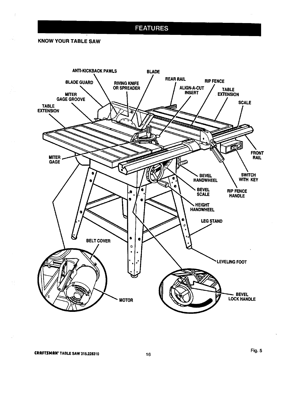
KNOW YOUR TABLE SAW
ANTI-KICKBACKPAWLS
BLADE
MITER
GAGEGROOVE
TABLE
EXTENSION
BLADE
REARRAIL RIPFENCE
RIVINGKNIFE
ORSPREADER ALIGN-A-CUT TABLE
INSERT EXTENSION
SCALE
GAGE
FRONT
RAIL
BELTCOVER
BEVEL SWITCH
HANDWHEEL WITH KEY
RIPFENCE
SCALE HANDLE
HANDWHEEL
LEGSTAND
'LEVELINGFOOT
MOTOR
BEVEL
LOCKHANDLE
Fig. 5
CRAFTSMAN"TABLESAW315.228310 16
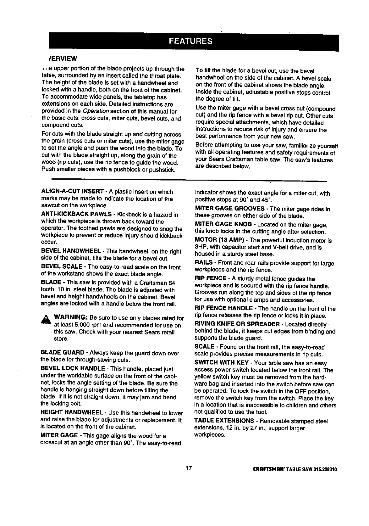
/ERVIEW
, ,,e upper portionof the blade projectsup throughthe
table, surroundedby an insertcalled the throat plate.
The height of the blade is set witha handwheel and
locked with a handle, both on the front of the cabinet.
To accommodate wide panels, the tabletop has
extensionson each side. Detailed instructionsare
providedinthe Operationsection of this manual for
the basiccuts: crosscuts, mitercuts, bevel cuts,and
compoundcuts.
For cuts with the blade straightup and cuttingacross
the grain(cross cuts or mitercuts), use the mitergage
to set the angle and pushthe wood into the blade. To
cut with the blade straight up, along the grain of the
wood (rip cuts), use the rip fence to guide the wood.
Push smaller pieces with apushblockor pushstick.
To tiltthe blade for a bevel cut, use the bevel
handwheel on the side of the cabinet. A bevel scale
on the front of the cabinet showsthe blade angle.
Insidethe cabinet, adjustable positivestopscontrol
the degree of tilt.
Use the miter gage with a bevel crosscut (compound
cut) and the rip fence with a bevel ripcut. Other cuts
require special attachments, which have detailed
instructions to reduce risk of injury and ensure the
best performance from your new saw.
Before attemptingto use your saw, familiarize yourself
withall operating features and safety requirements of
your Sears Craftsman table saw. The saw's features
are described below.
ALIGN-A-CUT INSERT -Apt_,stic insert onwhich
marks may be made to indicate the locationof the
sawcut on the workpiece.
ANTI-KICKBACK PAWLS - KickbackIs a hazard in
which the workpiece is thrownback toward the
operator. The toothed pawls are designed to snag the
workpieceto prevent or reduce injury should kickback
Occur.
BEVEL HANDWHEEL - This handwheel, on the right
side of the cabinet, tiltsthe blade for a bevel cut.
BEVEL SCALE - The easy-to-road scale on the front
of the work.standshowsthe exact blade angle.
BLADE -This saw is providedwith a Craftsman 64
tooth, 10 in. steel blade. The blade is adjustedwith
bevel and heighthandwheels on the cabinet. Bevel
angles are locked with a handle below the front rail.
WARNING: Be sure to use only blades rated for
at least 5,000 rpm and recommended for use on
this saw. Check with your nearest Sears retail
store.
BLADE GUARD - Always keep the guard down over
the blade for through-sawingcuts.
BEVEL LOCK HANDLE - This handle, placed just
under the worktable surfaceon the front of the cabi-
net, locksthe angle setting of the blade. Be surethe
handle is hangingstraightdown before tilting the
blade. If it is not straightdown, it may jam and bend
the lockingbolt.
HEIGHT HANDWHEEL - Use this handwheel to lower
and raise the blade for adjustmentsor replacement. It
is locatedon the front of the cabinet.
MITER GAGE - This gage alignsthe wood for a
crosscutat an angle other than 90". The easy-to-road
indicator showsthe exact angle for a mitercut, with
positivestopsat 90" and 45".
MITER GAGE GROOVES -The miter gage ddes in
these grooves on either side of the blade.
MITER GAGE KNOB -Located on the miter gage,
this knob locksin the cuttingangle after selection.
MOTOR (13 AMP) -The powerfulinductionmotor is
3HP, with capacitorstart and V-belt drive,and is
housedin asturdy steel base.
RAILS -Front and rear rails providesupportfor large
workpiecesend the ripfence.
RiP FENCE -A sturdy metal fence guidesthe
workpieceand is secured withthe rip fence handle.
Grooves run alongthe top and sidesof the ripfence
for usa withoptionalclamps and accessories.
RIP FENCE HANDLE -The handleon the front of the
rip fence releasesthe rip fence or locksit in place.
RIVING KNIFE OR SPREADER -Located directly.
behindthe blade, it keeps cut edges frombindingand
supportsthe blade guard.
SCALE -Found on the front rail,the easy-to-road
scale providesprecise measurementsin dp cuts.
SWITCH WITH KEY -Your table saw has an easy
access power switchlocated below the front rail.The
yellow switchkey must be removed fromthe hard-
ware bag and inserted into the switchbefore saw can
be operated. To lockthe switchinthe OFF position,
remove the switch key fromthe switch. Place the key
in alocation that is inaccessibleto childrenand others
notqualifiedto use the tool.
TABLE EXTENSIONS -Removable stampedsteel
extensions, 12 in. by 27 in., supportlarger
workpieces,
17 CRAFTSHAN"TABLESAW315.228310
Assembly is best done inthe area where the saw will be used. When you remove the table saw base, loose
parts, and hardware fromthe packingmatedals, check all items with the loose parts listand drawing. If you are
unsure about the descriptionof any part, refer to the drawing. If any parts are missing, delay assemblinguntil
you have obtained the missingpart(s).
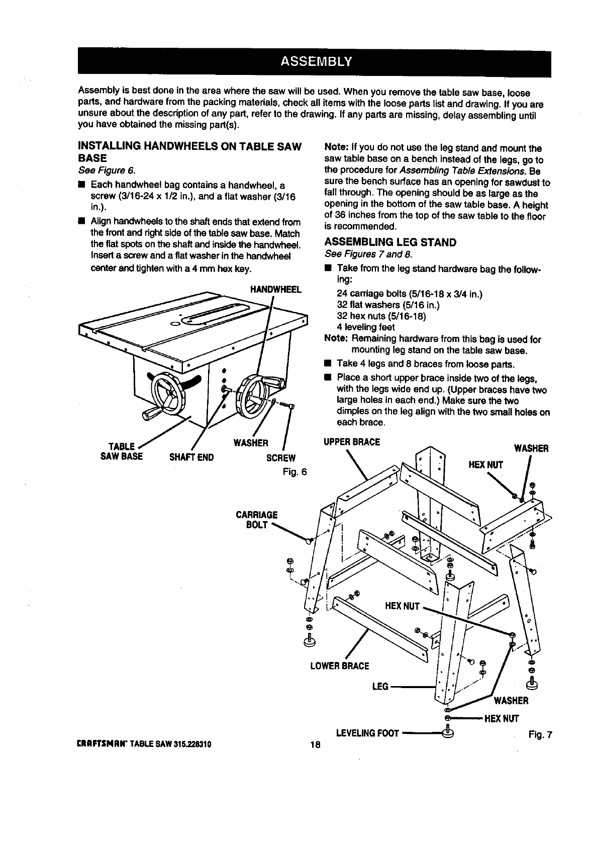
INSTALLING HANDWHEELS ON TABLE SAW
BASE
See Figure 6.
•Each handwheel bag containsa handwheel, a
screw (3/16-24 x 1/2 in.), and a flat washer (3/16
in.).
•Alignhandwheelsto the shaftendsthat extendfrom
the frontand rightsideof the table sawbase. Match
the fiat spotsonthe shaftand insidethe handwheeL
Insertascrewand a fiatwasherin the handwheel
centerandtightenwitha 4 mmhex key.
HANDWHEEL
Note: If you do not usa the leg stand and mount the
saw table base on abench instead of the legs, goto
the procedurefor Assembling Table Extensions. Be
sure the 'bench surfacehas an openingfor sawdustto
fall through.The opening shouldbe as large as the
opening in the bottomof the saw table base, A height
of 36 inchesfromthe top of the saw table to the floor
is recommended.
ASSEMBLING LEG STAND
See Figures 7 and 8.
•Take fromthe legstand hardware bag the follow-
ing:
24 carriagebolts (5/16,18 x 3/4 in.)
32 flat washers (5/16 in.)
32 hex nuts(5/16-18)
4 levelingfeet
Note: Remaininghardwarefrom thisbag is usedfor
mountingleg standon the table saw base.
•Take 4 legs and 8 bracesfrom loose parts.
•Place a shortupper brace insidetwo of the legs,
withthe legswide end up. (Upper braceshave two
large holes in each end.) Make sure the two
dimplesonthe leg alignwith the two small holes on
each brace.
TABLE WASHER
SAWBASE SHAFTEND SCREW
Fig. 6
UPPERBRACE
HEXNUT
%
WASHER
CARRIAGE
LOWERBRACE
LEG
[RRFTSMIIN" TABLESAW315,228310
HEXNUT
LEVELINGFOOT_Fig. 7
18
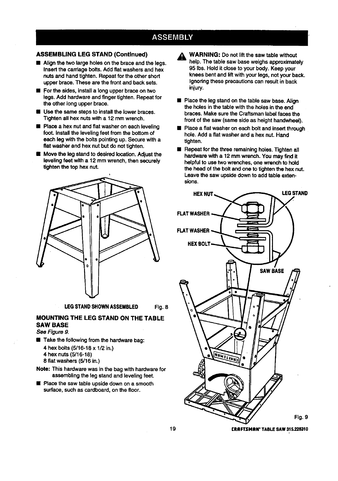
ASSEMBLINGLEGSTAND(Continued)
•Align the two large holes on the brace and the legs.
Insert the cardage bolts.Add flat washersand hex
nuts and hand tighten. Repeat forthe other short
upper brace. These are the front and backsets.
•For the sides, installa long upperbrace on two
legs. Add hardware and fingertighten. Repeat for
the other long upperbrace.
•Use the same steps to installthe lower braces.
Tighten all hex nutswith a 12 mm wrench.
•Place a hex nut and flat washer on each leveling
foot. installthe levelingfeet fromthe bottomof
each legwith the boltspointingup. Secure witha
fiat washer and hex nutbut do nottighten.
•Move the leg standto desiredlocation.Adjustthe
leveling feet witha12 mmwrench, then securely
tightenthe top hex nut.
_k WARNING: Do notliftthe saw table without
help. The table saw base weighs approximately
95 Ibs. Hold it closeto your body. Keep your
knees bent and liftwith your legs, notyour back.
Ignoringthese precautionscan result in back
injury.
•Place the legstand on the table saw base. Align
the holes inthe tablewith the holes in the end
braces. Make sure the Craftsman label faces the
front of the saw (same sideas heighthandwheel).
•Place a flat washeron each bolt and insertthrough
hole. Add a flat washerand ahex nut. Hand
tighten.
•Repeat for the three remainingholes.Tighten all
hardwarewith a 12 mmwrench. You may find it
helpfulto use two wrenches,one wrench to hold
the head of the boltand one to tightenthe hex nut.
Leave the saw upsidedownto add table exten-
sions.
HEXI, LEGSTAND
LEGSTANDSHOWNASSEMBLED Fig. 8
MOUNTING THE LEG STAND ON THE TABLE
SAW BASE
See Figure 9.
•Take the followingfrom the hardwarebag:
4 hex bolts(5/16-18 x 1/2 in.)
4 hex nuts (5/18-18)
8 flat washers (5/16 in.)
Note: This hardwarewas inthe bagwith hardwarefor
assemblingthe leg stand and levelingfeet.
•Place the saw table upsidedown on a smooth
surface, such as cardboard, on the floor.
Fig. 9
19 CRAFTSMRN"TABLESAW315.228310
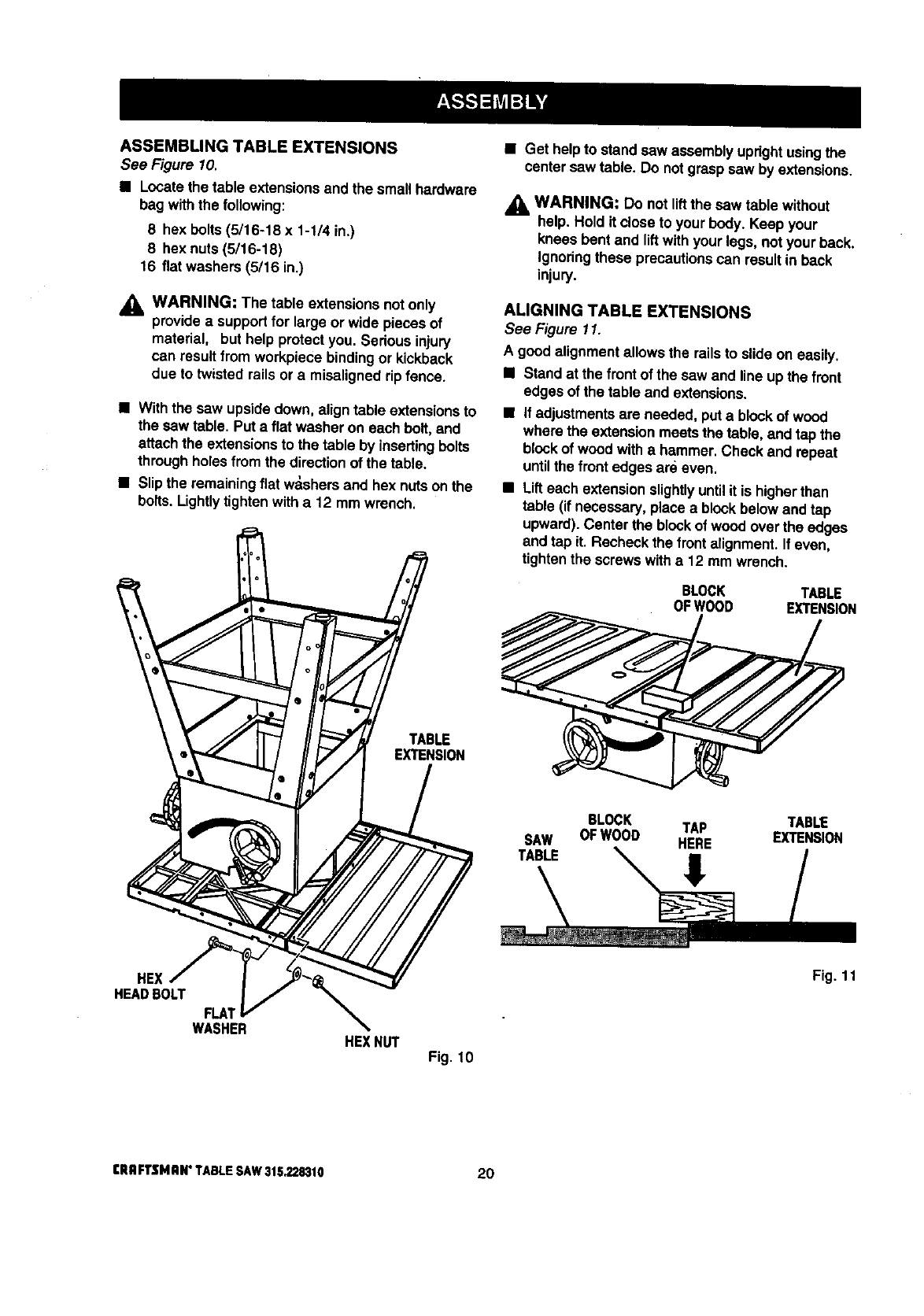
ASSEMBLING TABLE EXTENSIONS
See Figure 10.
•Locate the table extensionsand the smal_hardware
bag withthe following:
8 hex bolts(5/16-18 x 1-1/4 in.)
8 hex nuts (5/16-18)
16 fiat washers (5/16 in.)
,_ WARNING: The table extensions notonly
providea supportfor large or wide pieces of
material, but help protect you. Serious injury
can result from workpiece bindingor kickback
due to twisted rails or amisaligned rip fence.
• With the saw upsidedown, align table extensionsto
the sawtable. Put a flat washer on each bolt,and
attach the extensionsto the table by insertingbolts
throughholes from the directionof the table.
•Slip the remaining flat w_shers and hex nuts on the
bolts. Lightly tighten with a 12 mm wrench.
•Get help to standsaw assemblyupdght usingthe
centersaw table. Do notgrasp saw by extensions.
_i, WARNING: Do not lift the saw table without
help. Hold it closeto your body. Keep your
knees bent and liftwithyour legs, not your back.
Ignoringthese precautionscan result in back
injury.
ALIGNING TABLE EXTENSIONS
See Figure 11.
A good alignment allowsthe railsto slide on easily.
•Stand at the frontof the saw and line up the front
edgesof the table and extensions.
•if adjustmentsare needed, puta blockof wood
wherethe extensionmeetsthe table, and tap the
blockof wood with a hammer. Check and repeat
untilthe frontedges are even.
•Lifteach extensionslightlyuntilit is higherthan
table (if necessary, placea blockbelow and tap
upward). Center the blockof wood overthe edges
and tap it. Recheckthe front alignment.If even,
tightenthe screwswith a 12 mm wrer,_h.
BLOCK TABLE
OFWOOD EXTENSION
TABLE
EXTENSION
SAW
TABLE
BLOCK TAP TABLE
OFWOOD HERE EXTENSION
HEX
HEAD BOLT
FLA;
WASHER HE](NUT Fig. 10
Fig. 11
eRRFTSMRI_ TABLESAW3152.28310 20

INSTALLING THE REAR RAIL
See Figures 12-14.
,_ WARNING: Frontand rear rails must be
installedand carefullyaligned to reduce the risk
of kickback. Kickbackcan result in seriousinjury.
•From the carton,remove the rear rail and the
followinghardware:
6 square head bolts(5/16-18 x 1 in.)
6 flat washers (5/16 in.)
6 hex nuts(5/16-18)
Right and left end caps for rear rail
2 screws (5/32-32 x 1/2 in.)
Note: Remaininghardware from this hardware bag is
used for installingthe front rail and end caps.
•At the back of the table, put the square head bolts
inthe holes in the edge of the table and extensions
so the bolt headsextend outward 1/2 in.
•Underthe table, looselyattach washers and hex
nutsonto bolts.Slide the sloton the rear rail over
the bolts.Adjusteach boltto fit the rail closelyto
the table.
•Positionrail so that righthand edge extends 2-1/2
inches beyondtable extension.
•Pushthe rail against table and tighteneach nutwith
a 12 mm wrench.
•If the railjams and does notslide easily over the
bolts,re-alignthe table extensions.
•Put the end caps onthe rail ends. Insert the screws
and tightenwitha phillipshead screwdriver.
SLOT
REARRAIL
TABLE
EXTENSION
SQUARE HEXNUT
HEADBOLTS FLAT
WASHER Fig. 12
SQUARE
HEADBOLTS
TABLE
FLAT
WASHER
SCREW
NUT
REARRAIL
Fig. 13
ENDCAP
REAR OF SAW Fig. 14
21 CRRFTSNAN" TABLE SAW 315.228310
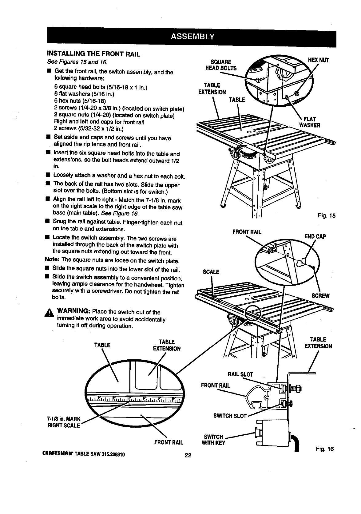
INSTALLING THE FRONT RAIL
See Figures 15and 16.
• Get the front rail the switchassembly, and the
followinghardware:
6 square head botts(5/16-18 x 1 in.)
6 fiat washers (5/16 in.)
6 hex nuts (5/16-18)
2 screws (1/4-20 x 3/8 in.) (located on switch plate)
2 square nuts (1/4-20) (located on switchplate)
Rightand left end caps for front rail
2 screws (5/32-32 x 1/2 in.)
• Set aside end caps and screws untilyou have
alignedthe dp fence and front rail.
•Insertthe six square head boltsinto the table and
extensions,so the bolt heads extend outward 112
in.
•Looselyattach awasher and a hex nut to each bolt.
•The back of the rail has two slots.Slide the upper
slotover the bolts. (Bottom slotis for switch.)
•Alignthe rail left to fight -Matchthe 7-1/8 in. mark
on the dghtscale to the dghtedge of the table saw
base (main table). See Figure 16.
•Snug the rail against table. Finger-tighteneach nut
onthe table and extensions.
•Locatethe switchassembly. The two screws are
installedthroughthe back of the switchplate with
the square nuts extendingout toward the front.
Note: The square nutsare loose on the switchplate.
•Slide the square nuts intothe lower slotof the rail.
•Slide the switchassembly to a convenient position,
leavingample clearance for the haedwheeLTighten
securelywitha screwdriver. Do nottightenthe rail
bolts.
A_ WARNING: Place the switchout of the
immediate work area to avoid accidentally
turningit off dudng operation.
TABLE TABLE
EXTENSION
SOUARE
HEADBOLTS
TABLE
EXTENSION
SCALE
FRONTRAIL
HEX NUT
FLAT
WASHER
Fig.!5
ENDCAP
SCREW
TABLE
EXTENSION
_IRIn.MARK
R_HTBCALE
SWITCH.
WITHKEY
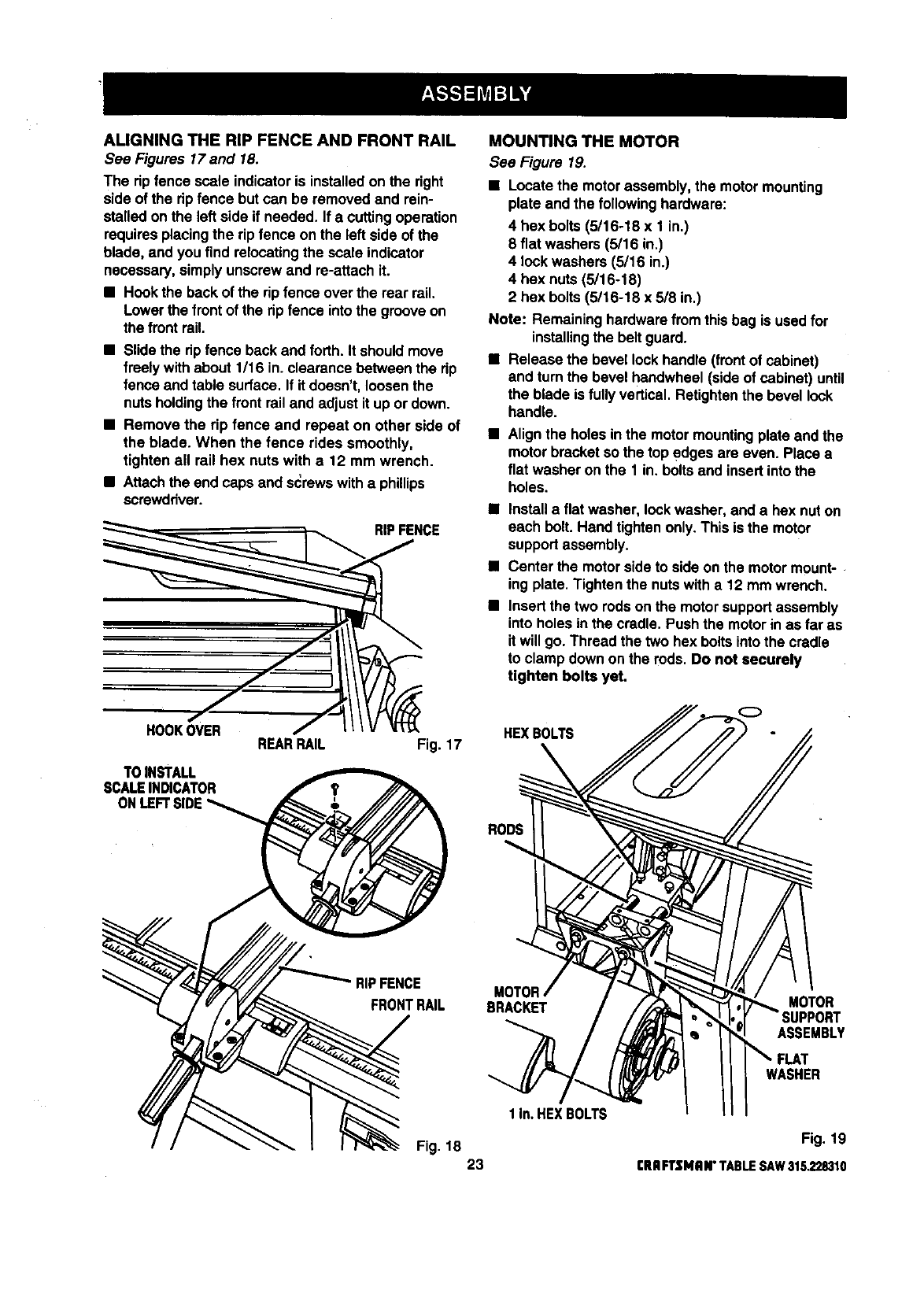
ALIGNINGTHERIPFENCEANDFRONTRAIL
See Figures 17and 18.
The ripfence scale indicatoris installedon the right
side of the rip fence but can be removed and rein-
stalled on the left side if needed. If a cuttingoperation
requiresplacing the rip fence on the left side of the
blade, and you find relocatingthe scale indicator
necessary, simply unscrewand re-attach it.
• Hookthe back of the rip fence over the rear rail.
Lower the frontof the rip fence into the grooveon
the front rail.
•Slide the rip fence back and forth. It should move
freely withabout 1/16 in. clearance between the rip
fence and table surface. If it doesn't, loosenthe
nuts holdingthe front rail and adjust it up or down.
•Remove the rip fence and repeat on other side of
the blade. When the fence rides smoothly,
tighten all rail hex nuts with a12 mm wrench.
•Attachthe end caps and s_rews witha phillips
screwdriver.
NCE
oo
REARRAIL Fig. 17
TOINSTALL
SCALEINDICATOR
ONLEFT
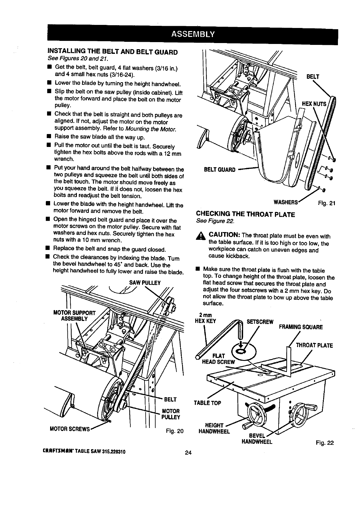
MOUNTING THE MOTOR
See Figure 19.
•Locate the motorassembly, the motor mounting
plate and the followinghardware:
4 hex bolts (5/16-18 x 1 in.)
8 flat washers (5/16 in,)
4 lockwashers (5/16 in.)
4 hex nuts(5/16-18)
2 hex bolts(5/16-18 x 5/8 in.)
Note: Remaininghardwarefromthis bag is used for
installingthe belt guard.
•Release the bevel lock handle (frontof cabinet)
and turn the bevel handwheel (sideof cabinet) until
the blade is fullyvertical. Retightenthe bevel lock
handle.
•Align the holes inthe motormountingplate and the
motor bracketso the top edges are even. Place a
flat washer on the 1 in. boltsand insert into the
holes.
•Installaflat washer, lockwasher, and a hex nut on
each belt. Hand tightenonly.This is the motor
supportassembly.
•Center the motorside to side on the motor mount-
ing plate. Tighten the nutswitha 12 mm wrench.
•Insert the two rodson the motor supportassembly
into holes in the cradle. Pushthe motor in as far as
it will go. Thread the two hex bolts intothe cradle
to clamp down on the rods. Do not securely
tighten bolts yet.
HEX BOLTS
RODS
RIPFENCE
FRONTRAIL MOTOR
BRACKET MOTOR
ASSEMBLY
1 In.HEXBOLTS
WASHER
Fig. 18 Fig. 19
23 CRRFTSNRN"TABLESAW315.228310
INSTALLINGTHEBELTANDBELTGUARD
See Figures20 and 21.
•Get the belt, belt guard, 4 flat washers(3/16 in.)
and 4 smallhex nuts (3/16-24).
•Lower the blade by turningthe heighthandwheel.
• Slipthe belton the saw pulley(insidecabinet). Lift
the motorforwardand place the belt on the motor
pulley.
•Check that the belt is straightand both pulleysare
aSgned. If not, adjustthe motoron the motor
supportassembly. Refer to Mountingthe Motor.
•Raise the saw blade all the way up.
•Pullthe motor out untilthe belt is taut. Securely
tightenthe hex boltsabove the rods witha 12 mm
wrench.
•Put your hand around the belthalfwaybetween the
two pulleysand squeeze the be_tuntil bothsidesof
the belt touch.The motor shouldmove freelyas
you squeeze the belt. If i_does not, loosenthe hex
boltsand readjustthe belttension.
•Lower the blade with the heighthandwheel.Liftthe
motorforwardand remove the belt.
•Open the hinged belt guard and place it over the
motorscrews on the motorpulley. Secure withfiat
washers and hex nuts. Securely tightenthe hex
nuts witha 10 mm wrench.
• Replace the belt and snap the guardclosed.
•Checkthe clearances by indexingthe blade.Turn
the bevel hendwheel to 45" and back. Use the
heighthandwheelto fully lower and raise the blade.
SAWPULLEY
MOTORSUPPORT
ASSEMBLY
MOTORSCREWS
rRRFTSMRN"TABLESAW315,228310
BELT
BELTI
MOTOR
Fig. 20
24
CHECKING THE THROAT PLATE
See Figure 22.
Fig. 21
j_ CAUTION: The throatplate must be even with
the table surface. If it is too highor too low,the
workpiece can catch on uneven edges and
cause kickback.
• Make surethe throat plate is flush withthe table
top. To change heightof the throat plate, loosenthe
flat head screw that securesthe throat plate and
adjust the four setscrewswitha 2 mm hex key. Do
not allow the throatplate to bow up above the table
surface.
2mm
HEXKEY SETSCREW FRAMINGSQUARE
IROATPLATE
TABLETOP
HEIGHT
HANDWHEEL BEVEL
HANDWHEEL Fig. 22
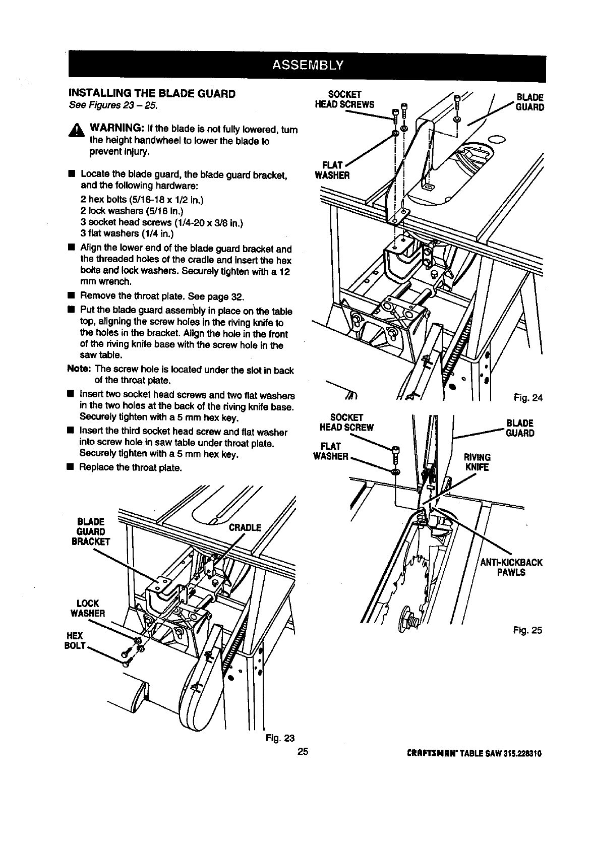
INSTALLING THE BLADE GUARD
See Figures 23 -25.
WARNING: If the blade is not fully lowered, tum
the heighthandwheel to lower the blade to
prevent injury.
•Locatethe blade guard, the blade guardbracket,
and the followinghardware:
2 hex bolts (5/16-18 x 1/2 in.)
2lockwashers (5/16 in.)
3 socket head screws (1/4-20 x 3/8 in.)
3fiat washers (1/4 in.)
•Align the lower end of the blade guard bracketand
the threaded holes of the cradle and insertthe hex
boltsand _ockwashers. Securely tk3htanwith a12
mm wrench.
•Remove the throat plate. See page 32.
•Put the blade guard assemblyin place on the table
top, aligningthe screw holes inthe rivingknifeto
the holes in the bracket. Align the hole inthe front
of the rivingknifebase withthe screw hole in the
saw table.
Note: The screw hole is located underthe slot in back
of the throat plate.
•Inserttwo socket head screws and two flat washers
inthe two holes at the beck of the dyingknifebase.
Securelytightenwith a 5 mm hex key.
•Insertthe thirdsocket head screw and flat washer
into screw hole in saw table underthroat plate.
Securelytightenwith a 5 mm hex key.
•Replace the throat plate.
SOCKET
HEADSCREWS
FLM
WASHER
SOCKET
HEADSCREW
FLAT RIVING
KNIFE
BLADE
Fig. 24
BLADE
BLADE
GUARD
BRACKET
_NTI-KICKBACK
PAWLS
LOCK
WASHER
HEX Fig. 25
Fig. 23
25 CRRFTSNnN"TABLESAW315.228310

ALIGNINGTHERIVINGKNIFEWITHTHE
BLADE
See Figures26 -28.
_l, WARNING: Make sure the switchis off, the
switchkey is removed, and your saw is
unplugged. Failure to do so could result in
accidental starting, causing serious personal
injury.
The rivingknife must be aligned withend centered
overthe blade.
_I, WARNING: It is importantto installand adjust
the riving knifecorrectly. Poor alignment could
cause kLckbackand throw the workpiece at the
operator.
•Raisethe blade guard.
• Place a framing square or straightedgebeside the
blade on the left. See Figure 26.
• Loosen the front screw on the riving knife with a
5 mm hex key. See Figure 27.
•Center the rivingknifeover the blade. See Figure
28.
•Securelytightenthe screw with a5mm hex key.
RMNG KNIFE
BLADE
SAW
TABLE
FRAMINGSQUARE Fig. 26
BLADE GUARD
RIVINGKNIFE
BLADE
/
Fig. 27
RIVINGKNIFE
I/
FRAMING
SQUARE
BLADE
_ROAT
PLA_
/
TOPVIEWOFSAWWITHRIVING
KNIFESHOWNCENTEREDOVERBLADE Fig. 28
rRIIfTSMRN" TABLESAY/315.22S310 26
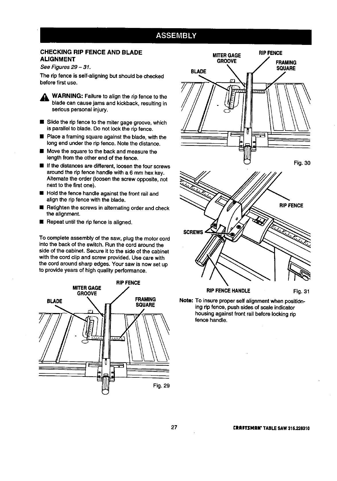
CHECKING RIP FENCE AND BLADE
ALIGNMENT
See Figures 29 -31.
The rip fence is self-aligningbut shouldbe checked
before first use.
_, WARNING: Failure to align the rip fence to the
blade can cause jams and kickback,resultingin
seriouspersonal injury.
•Slide the ripfence to the mitergage groove, which
is parallelto blade. Do not lockthe rip fence.
•Place a framing square against the blade,with the
longend underthe ripfence. Note the distance.
•Movethe square to the back and measure the
lengthfrom the other end of the fence.
•If the distancesare different, loosenthe four screws
around the ripfence handlewith a6 mm hex key.
Alternatethe order (loosenthe screw opposite,not
next to the first one).
•Holdthe fence handle against the front rail and
alignthe rip fence withthe blade.
•Retightenthe screws in alternatingorderand check
the alignment.
•Repeat untilthe rip fence is aligned.
To complete assemblyof the saw, plug the motorcord
into the back of the switch. Run the cord around the
side of the cabinet. Secure it to the side of the cabinet
withthe cord clip and screw provided. Use care with
the cord around sharp edges. Your saw is now set up
to provide years of high quality performance.
BLADE
MITERGAGE
GROOVE
RIPFENCE
FRAMING
SQUARE
€
BLADE
MITERGAGE
GROOVE
RIPFENCE
FRAMING
SOUARE
Fig. 30
RIP FENCE
RIPFENCEHANDLE Fig. 31
Note: To insureproperself alignmentwhen positiOn-
ing rip fence, push sidesof scale indicator
housingagainst front railbefore lookingrip
fence handle.
Fig. 29
27 CRaFTSMRN"TABLESAW315.228310
To avoid unnecessarysetupsand adjustments,a
goodpractice is to check your setupscarefullywith a
framing square and make practicecuts in scrapwood
before making finish cuts in goodworkpieces. Do not
start any adjustmentsuntil you have checkedw_tha
square and made test cuts to be sure adjustmentsare
needed.
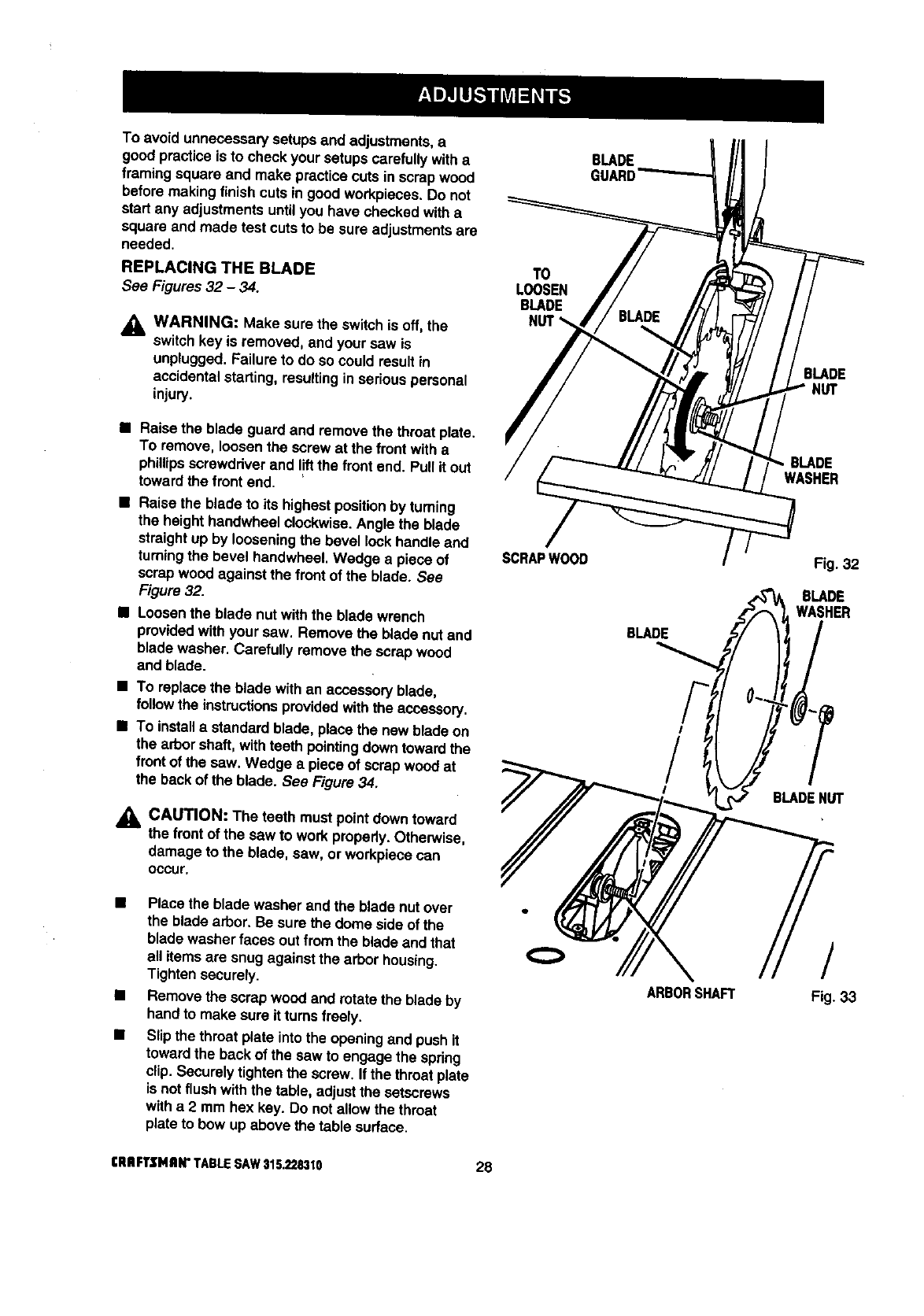
REPLACING THE BLADE
See Figures 32 -34.
_1, WARNING: Make sure the switchis off,the
switchkey is removed, and your saw is
unplugged. Failure to do so could result in
accidentalstarting, resultinginseriouspersonal
injury.
T0
LOOSEN
BLADE
BLADE
GUARD
BLADE
•Raise the blade guard and remove the throat plate.
TO remove, loosenthe screw at the front witha
phillipsscrewddver and I!ftthe front end. Pull it out
toward the front end.
•Raise the blade to its highestpositionby turning
the height handwheel clockwise.Angle the blade
straightup by looseningthe bevel lockhandle and
turningthe bevel handwheet.Wedge a piece of
scrapwood against the frontof the blade. See
Figure 32.
•Loosenthe blade nut withthe bible wrench
providedwithyour saw. Remove the blade nut and
blade washer. Carefully remove the scrap wood
and blade.
•To replace the blade with an accessoryblade,
follow the instructionsprovidedwiththe accessory.
• To install a standard blade, place the new blade on
the arbor shaft,withteeth pointing down towardthe
front of the saw, Wedge a piece of scrap woodat
the back of the blade. See Figure 34.
CAUTION: The teeth must pointdown toward
the front of the saw to work properly.Otherwise,
damage to the blade, saw, or workpiececan
occur.
SCRAPWOOD
BLADE
I
/
I
BLADE
WASHER
BLADEHUT
•Place the blade washer and the blade nut over
the blade arbor. Be sure the dome side of the
blade washer faces out from the blade and that
all items are snug againstthe arbor housing.
Tightensecurely.
•Remove the scrapwood and rotate the blade by
hand to make sure it turns freely.
•Slip the throat plate intothe openingand push it
toward the back of the saw to engage the spring
clip,Securely tightenthe screw. If the throat plate
is notflush with the table, adjust the setscrews
with a2mrn hex key. [3o not allow the throat
plateto bow up above the table surface.
ARBORSHAFT
/
Fig. 33
[RRFTSMRW TABLESAW$15.2283t0 28

SCRAPWOOD BLADEGUARD
BLADE NUT
WASHER
TOTIGHTEN
BLADENUT Fig. 34
HEELING (PARALLELING) THE SAWBLADE
TO THE MITER GAGE GROOVE
See Figures 35 -37.
DO NOT loosen any screws for this adjustment
until you have checked with a square and made
test cuts to be sure adjustments are necessary.
Once the screws are loosened, these Items must
be reset.
_k WARNING: Make sure the switchis off, the
switchkey is removed, and your saw is un-
plugged. Failure to do so couldresult in acciden-
tal starting, resultingin seriouspersonal injury.
_l, WARNING: The sawblade must be parallel to
the mitergage groove so the wood does not
bind, resultingin kickback.You couldbe hitor
cut.
• Liftthe blade guard. Raise the blade all the way by
turning the height handwheel.
•Mark one of the sawblade teeth at the front of the
blade. Place aframing square beside the blade and
just touching the marked tooth. Measure the
distance to the right miter gage groove.
• Turn the sawblade so the marked tooth is at the
back.
•Move the square to the rear and again measure the
distanceto the rightmitergage groove. If the
distancesare the same, the blade and the miter
gage groove are parallel.
/
MITERGAGEGROOVE
FRAMINGSQUARE
Fig. 35
(_ FRAMING
SQUARE
f
MITERGAGEGROOVE Fig. 36
•If the distancesmeasured are different,adjust the
mechanismunderneaththe saw.
j_ WARNING: When reaching under the saw
table, wear gloves or first remove the blade.
Accidentalcontactwith the blade couldcause a
cut resultingin seriouspersonal injury.
•Remove the throat plate by loosening the front
screw witha phillips screwdriver.Liftthe throat
plateand pull it out by the front end.
•Lowerthe blade completelywiththe height
handwheel.You can then access the table brackets
throughthe throat plate opening.
•From the back, loosenthe three rear screws
holdingreartable bracketusinga 12 mm wrench.
•If the toothwas too far from the square'sblade,
move the rear brackettoward the mitergage
groove.Tap with a block of wood and hammer.
29 CRRFTSNRN"TABLESAW315.228310
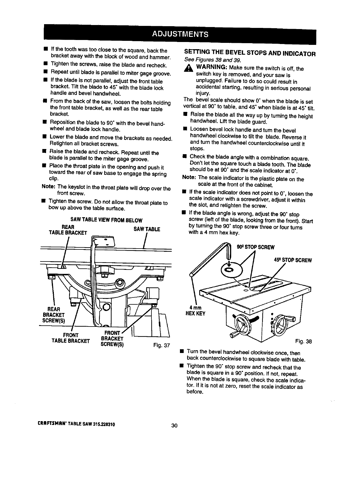
•If the tooth was too close to the square, back the
bracket away withthe block of wood and hammer.
• Tightenthe screws,raise the blade and recheck.
•Repeat untilblade is parallel to mitergage groove.
•If the blade Is not parattel,adjust the front table
bracket.Tilt the blade to 45" with the blade lock
handleand bevel handwheel.
•From the back of the saw, toosenthe bolts holding
the front table bracket, as well as the reartable
bracket.
•Repositionthe blade to 90" with the bevel hand-
wheel and blade lock handle.
•Lower the blade and move the bracketsas needed.
Retightenall bracket screws.
•Raise the blade and recheck. Repeat untilthe
blade is parallelto the miter gage groove.
•Place the throat plate in the openingand push it
towardthe rearof saw base to engage the spring
clip.
Note: The keyslotin the throat plate willdrop overthe
frontscrew.
•Tightenthe screw. Do not allow the throat plateto
bow up above the table surface.
SAWTABLEVIEWFROMBELOW
REAR SAWTABLE
TABLEBRACKET /
SETTING THE BEVEL STOPS AND INDICATOR
See Figures 38 and 39.
,_ WARNING: Make sure the switchis off, the
switchkey is removed, and your saw is
unplugged. Failure to do so could result in
accidentalstarting, resultingin serious personal
injury.
The bevel scale shouldshow 0" whenthe blade is set
verticalat 90" to table, and 45" when blade is at 45" tilt.
• Raise the blade all the way up by turningthe height
handwheel. Liftthe blade guard.
•Loosenbevel lookhandleand turn the bevel
handwheel clockwiseto tiltthe blade, Reverse it
and turn the handwheel counterclockwiseuntilit
stops.
•Check the blade angle with a combinationsquare.
Don't let the square touch a bladetooth.The blade
shouldbe at 90" and th_ scale indicatorat 0".
Note: The scale indicatoristhe plasticplate on the
scale at the front of the cabinet.
•If the scale indicatordoes notpointto 0", loosenthe
scale indicatorwitha screwdriver,adjustit within
the s_ot,and retightenthe screw.
•If the blade angle is wrong, adjustthe 90" stop
screw (left of the blade, lookingfrom the front). Start
by turningthe 90" stopscrew three or four turns
with a 4 mm hex key.
90_STOPSCREW
45_STOPSCREW
REAR
BRACKET
SCREW(S)
FRON
FRONT BRACKET
TABLEBRACKET SCREW(S)
4 mm
HEXKEY
Fig. 37
Fig. 38
•Turn the bevel handwhee]clockwiseonce, then
back counterclockwiseto square blade withtable.
•Tighten the 90" stop screw and recheckthat the
blade is square in a 90" position,If not, repeat,
When the blade is square, check the scale indica-
tor. If it is notat zero, resetthe scale indicatoras
before.
CRAFTSMAN*TABLESAW315.228310 30
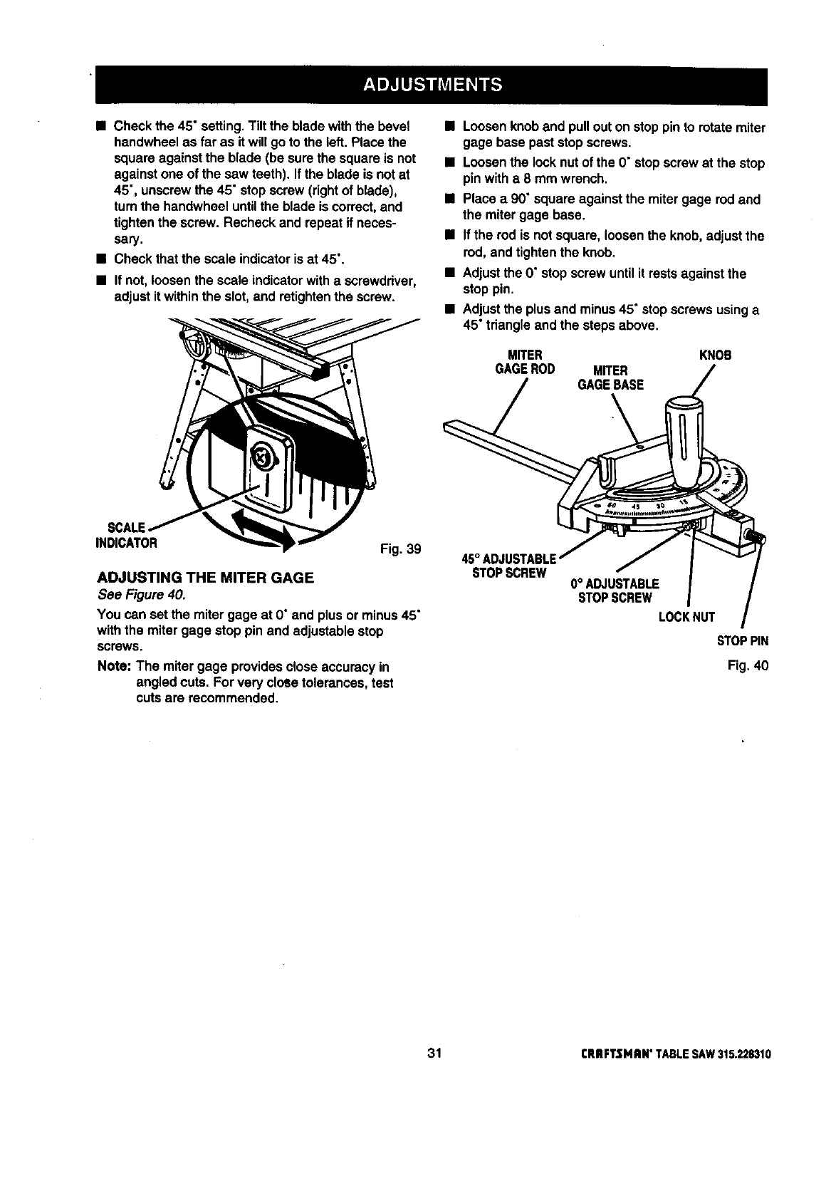
•Check the 45" setting.Tilt the blade withthe bevel
handwheel as far as it will go to the left.Place the
square against the blade (be surethe square is not
against one of the saw teeth). Ifthe blade is not at
45", unscrewthe 45" stop screw (rightof blade),
turnthe handwheel untilthe blade is correct,and
tightenthe screw. Recheck and repeat if neces-
sary.
•Check that the scale indicatoris at 45°.
•If not, loosen the scale indicatorwith a screwdriver,
adjust it withinthe slot,and retightenthe screw.
SCALE
INDICATOR Fig. 39
ADJUSTING THE MITER GAGE
See Figure 40.
You can set the mitergage at O"and plus or minus45"
withthe miter gage stop pin and adjustable stop
screws
Note: The miter gage providesclose accuracyin
angled cuts. For very cloSetolerances, test
cuts are recommended.
•Loosenknob and pullout on stoppin to rotatemiter
gage base past stop screws.
•Loosenthe locknutof the 0" stop screwat the stop
pin with a8 mm wrench.
•Place a 90" square against the miter gage rod and
the mitergage base.
•If the rod is notsquare, loosen the knob, adjust the
rod, and tightenthe knob.
•Adjustthe 0" stop screw untilit rests against the
stop pin.
•Adjustthe plus and minus45" stopscrews usinga
45" tdangle and the steps above.
MITER
GAGEROD MITER
GAGEBASE
KNOB
STOPSCREW 0° ADJUSTABLE
STOPSCREW
LOCKNUT
STOPPIN
Fig. 40
31 rRRFTSMRN" TABLESAW315.228310
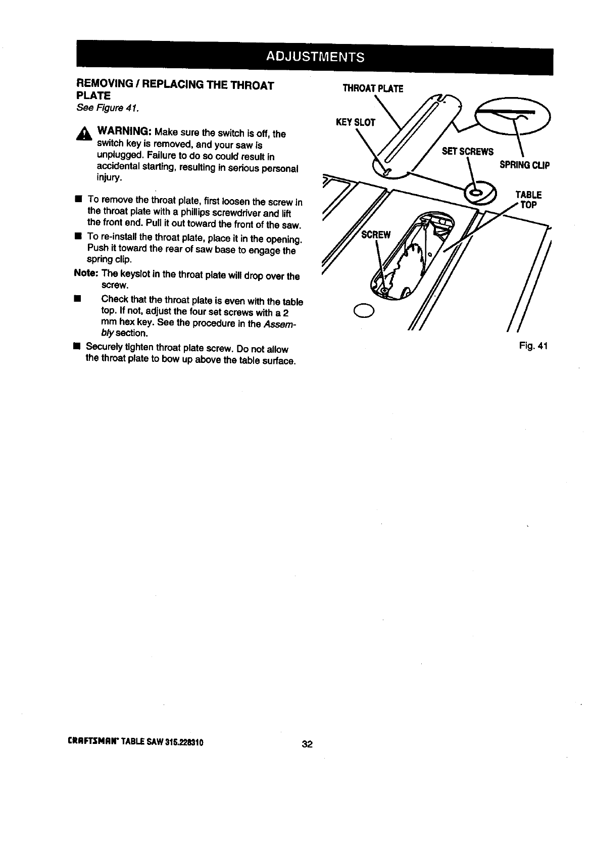
REMOVING /REPLACING THE THROAT
PLATE
See Figure 41.
,_ WARNING: Make sure the switch is off,the
switchkey is removed, and your saw is
unplugged. Failureto do so could result in
accidentalstarting, resultingin sadous personal
injury.
•To remove the throat plate, firstloosenthe screw in
the throat platewith a phillipsscrewdriverand lift
the front end. Pull it outtoward the frontof the saw.
•To re-installthe throat plate, place It inthe opening.
Push it towardthe rear of saw base to engage the
spdngclip.
Note: The keyslotinthe throat plate willdrop over the
screw.
•Check that the throat plate is even withthe table
top. If not, adjust the four set screwswith a 2
mm hex key. See the procedureinthe Assam-
b/ysection.
•Socure_ytightenthroat plate screw. Do not allow
the throat plateto bow up above the table surface.
THROATPLATE
KEYSLOT
SPRINGCLIP
TABLE
Fig. 41
CRIIFI3MAN" TABLESAW31tL_8310 32
BASIC OPERATION OF THE TABLE SAW
A table saw can be used for straight-linecutting
operationssuch as crosscutting, ripping,mitering,
beveling,and compoundcutting. It can make dado or
moldingcuts with optionalaccessories.
The three-prong plug must be pluggedinto a match-
ing outletthat is propeity installed and grounded
accordingto all local codes and ordinances. Improper
connectionof the equipment can result in electdc
shock. Check with an electrician or service personnel
if you are unsure about proper grounding, Do not
modifythe plug;if it will notfit the outlet, have the
correctoutlet installed by aqualifiedelectrician.Refer
to the Electricalpage of this manual.
Note: This table sew is designed to cut wood and
wood compositionproductsonly.
CAUSES OF KICKBACK
Kickbackcan occurwhen the blade stallsor binds,
kickingthe workpieceback toward you with great
force end speed, if your hands are near the sewblade,
they may be jerked loose fromthe workpieceand may
contactthe blade. Obviously, kickbackcan cause
seriousinjury, and it is well worth using precautionsto
avoidthe risks.
Kickbackcan be caused by any action that pinches
the blade in the wood, such as the following:
•Makinga cut with incorrectblade depth
•Sawing intoknots or nails in the workpiece
•Twistingthe wood while making acut
•Failingto supportwork
•Forcinga cut
•Cuttingwarped or wet lumber
•Usingthe wrongblade for the type of cut
•Not following correct operatingprocedures
•Misusingthe saw
•Fai{ingto use the ant'vkickback pawls
• Cutting witha dull, gummed-up, or improperlyset
blade
AVOIDING KICKBACK
•Always use the correct blade depth setting. The
top of the blade teeth should clear the workpiece
by 1/8 in. to 1/4 in.
•Inspectthe work for knotsor nails before beginning
a cut. Knockout any loose knotswitha hammer.
Never saw into a loose knot or nail.
• Always use the rip fence when rip cuttingand the
mitergage when crosscutting.This helpsprevent
twisting the wood in the cut.
• Always use clean, sharp, and properly-set blades.
Never make cuts with dull blades.
•To avoid pinchingthe blade,supped the work
properlybefore beginning acut.
•When making a cut, use steady, even pressure.
Never force cuts.
•Do notcut wet or warped lumber.
• Always hold your workpiecefirmlywithboth hands
or with pushsticks.Keep yourbody in a balanced
positionto be ready to resistkickbackshouldit
occur. Never stand directlyin line withthe blade.
•Use the dghttype of blade for the cut beingmade.
CUTTING AIDS
See Figure 42.
Pushsticksare devices used for safely pushinga
workpiecethroughthe blade insteadof usingyour
hands. They can be made in varioussizes and
shapes from scrap wood to use in a specificproject.
The stick must be narrewet than the workpiece, witha
90" notch in one end and shapingfor a gripon the
other end.
A pushblockhas a handle fastened by recessed
screws from the underside, Use it on non-through
cuts.
_IL CAUTION: Be sure the screw is recessedto
avoid damaging the saw or workpiece.
PUSHBLOCKS
PUSHSTICKS
Fig.42
Afeatherboard is usedwhen it is notpracticalto use
the miter gage, usuallydue to the size of the
workpieca. The end is angled, withanumber of short
kerfs to give a friction hold on the workpiece. Use a
C-clamp to lock it in place on the table. Test that it
could resist kickback.
,_ WARNING: Place the featherboardagainst the
uncut portionof the workpiece,to avoid kickback.
33 CRBFTSMRN"TABLESAY/$15.22_10
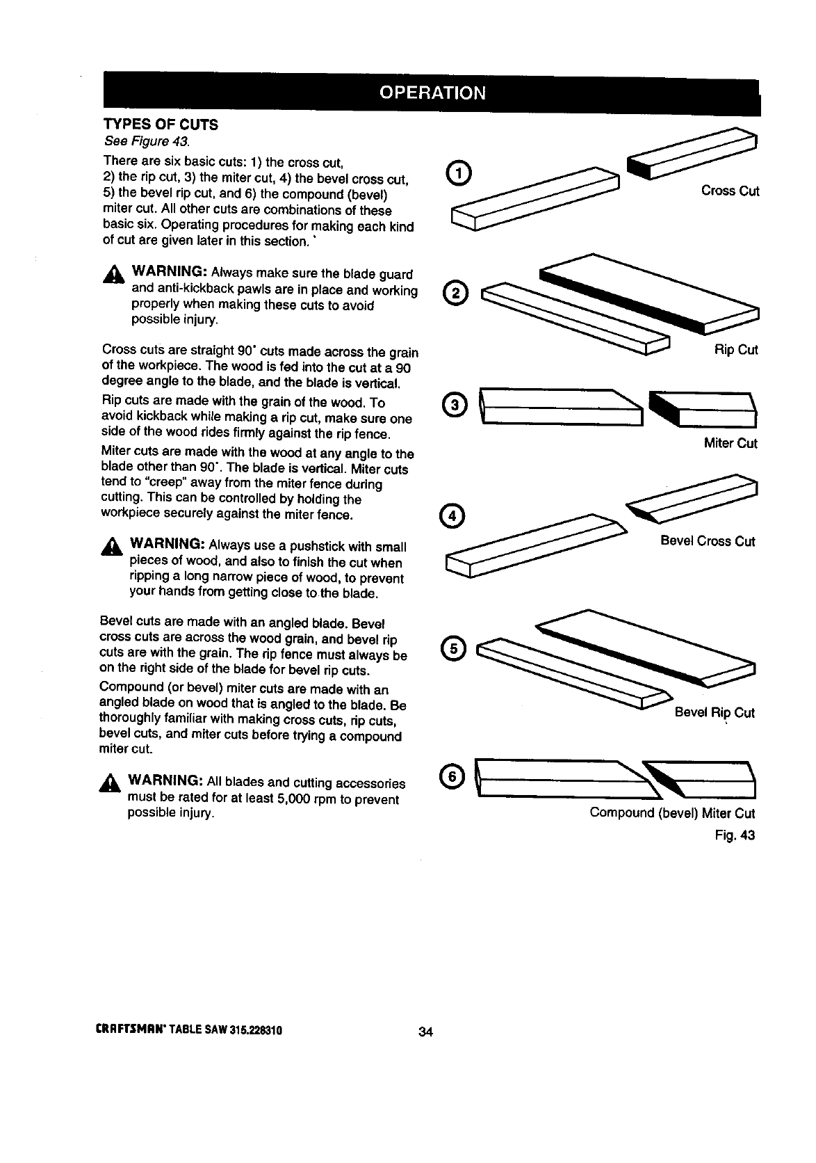
TYPES OF CUTS
See Figure 43.
There are six basic cuts: t) the crosscut,
2) the rip cut, 3) the mitercut, 4) the bevel crosscut,
5) the bevel rip cut, and 6) the compound(bevel)
miter cut. All other cuts are combinations of these
basicsix. Operating proceduresfor making each kind
of cut are given later in this sect'lon."
_. WARNING: Always make sure the blade guard
and anti-kickbackpawls are in place and working
properlywhen making these cuts to avoid
possible injury.
Cross cuts are straight90" cuts made across the grain
of the workpiece. The wood is fed into the cut at a 90
degree angle to the blade, and the blade is vertical,
Rip cuts are made withthe grain of the wood. To
avoid kickbackwhile making a rip cut, make sure one
side of the wood rides firmly against the rip fence.
Miter cuts are made with the wood at any angle to the
blade other than 90". The blade is vertical. Miter cuts
tend to "creep" away from the miter fence during
cutting.This can be controlledby holdingthe
workpiece securely against the miterfence.
_, WARNING: Always use a pushstickwith small
pieces of wood, and also to finish the cut when
rippinga longnarrowpiece of wood, to prevent
your hands from gettingcloseto the blade.
Bevel cuts are made with an angled blade. Bevel
crosscuts are across the wood grain, and bevel rip
cuts are with the grain. The rip fence must always be
on the rightside of the blade for bevel rip cuts.
Compound (or bevel) miter cuts are made with an
angled blade on wood that is angled to the blade. Be
thoroughlyfamiliar with making cross cuts, dp cuts,
bevel cuts, and miter cuts before tryinga compound
mitercut.
_, WARNING: All blades and cuttingaccessodes
must be rated for at least 5,000 rpm to prevent
possible injury.
Cross Cut
®
Miter Cut
o
Bevel Cross Cut
Bevel Rip Cut
Compound (bevel) Miter Cut
Fig. 43
tRRFTSNRN" TABLESAW315.228310 34
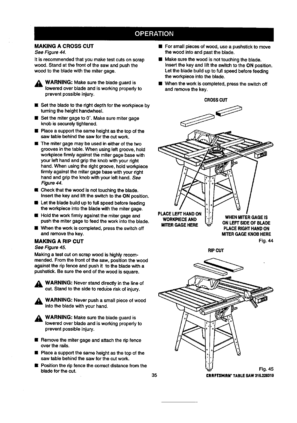
MAKING A CROSS CUT
See Figure 44.
It is recommended that you make test cuts on scrap
wood. Stand at the frontof the saw and push the
wood to the blade with the miter gage.
_1= WARNING: Make sure the blade guard is
lowered over blade and is working properlyto
preventpossibleinjury.
• Set the bladeto the fightdepth forthe workpieceby
tumingthe height handwheel.
•Set the mitergage to 0". Make sure mitergage
knob is securelytightened.
•Place asupportthe same heightas the top of the
saw table behind the saw for the cut work.
•The mitergage may be usedin either of the two
g_:_ovesin the table. When usingleftgroove, hold
workpiecefirmlyagainst theemitergage base with
your left hand and gripthe knobwithyour right
hand.When usingthe rightgroove, holdworkpiece
firmlyagainst the mitergage base withyour right
hand and gripthe knobwith your left hand. See
Figure 44.
•Check that the wood is nottouchingthe blade.
Insert the key and liftthe switchto the ON position.
•Let the blade buildup to fullspeed before feeding
the workpieceintothe blade withthe mitergage.
•Hold the workfirmlyagainst the mitergage and
push the miter gage to feed the workinto the blade.
•When the work is completed, pressthe switchoff
and removethe key.
MAKING A RIP CUT
See Figure 45.
Making a test cut on scrap wood is highlyrecom-
mended. From the front of the saw, posltioothe wood
against the rip fence and push it to the blade witha
pushstick.Be sure the end of the wood is square.
•For small piecesof wood, use a pushstickto move
the wood into and past the blade.
•Make sure the wood is nottouchingthe blade.
Insert the key and liftthe switchto the ON position.
Let the blade build upto full speed beforefeeding
theworkpieceintotheblade.
• When thework iscompleted,presstheswitchoff
and removethekey,
CROSSct,rr
PLACELEFT HANDON
WORKPIECEAND
Mn'ER GAGE HERE
WHENMITERGAGEIS
ONLEFTSIDEOFBLADE
PLACERIGHTHANDON
MITERGAGEKNOBHERE
Fig. 44
RIPCUT
WARNING: Never stand directlyIn the line of
cut. Stand to the side to reduce riskof injury.
WARNING: Never push a smallpiece of wood
into the blade with your hand.
_1= WARNING: Make surethe blade guard is
lowered over blade and is workingproperlyto
prevent possible injury.
•Remove the mitergage and attachthe ripfence
over the rails.
•Place a supportthe same heightas the top of the
saw table behindthe saw for the cut work.
•Positionthe rip fence the correct distancefromthe
blade forthe cut. 35
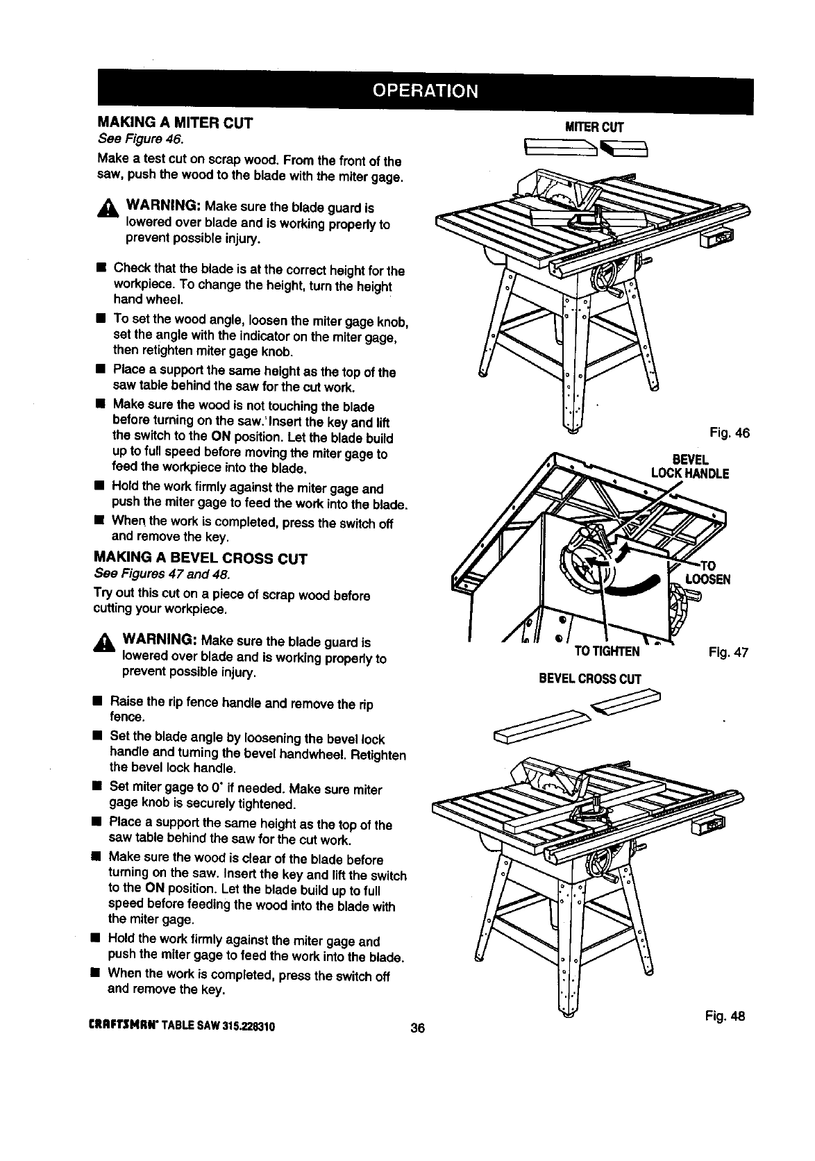
MAKINGA MITERCUT
See Figure 46.
Make atest cut on scrap wood. From the front of the
caw. push the wood to the blade with the miter gage.
_1, WARNING: Make sure the blade guardis
loweredover blade and is workingpropedy to
prevent possible injury.
•Check that the blade is at the correct heightfor the
workpiece.To change the heighL turn the height
hand wheel.
•To set the wood angle, loosenthe mitergage knob,
set the angle withthe indicatoron the mitergage,
then retightenmitergage knob.
•Place asupportthe same heightas the top of the
saw table behind the saw for the cut work.
•Make surethe woodis nottouchingthe blade
before turningon the saw.' Insert the key and lift
the switchto the ON position.Let the blade build
upto full speed before movingthe mitergage to
feed the workpieceintothe blade.
•Ho_dthe work firmly against the miter gage aod
pushthe miter gage to feed the work intothe blade.
•When the workis completed, pressthe switchoff
and remove the key,
MAKING A BEVEL CROSS CUT
See Figures47 and 48.
Try outthis cut on a piece of scrap wood before
cuttingyour workpiece.
_k WARNING: Make sure the blade guardis
loweredover blade and is workingpropedy to
prevent possibleinjury.
•Raise the rip fence handleand remove the rip
fence.
•Set the blade angle by loosening the bevel lock
handle and turningthe bevel handwheel. Retighten
the bevel lockhandle.
•Set mitergage to 0" if needed. Make sure miter
gage knob is securely tightened.
•Place a supportthe same heightas the top of the
saw table behind the saw for the cut work.
•Make sure the wood is clear of the blade before
turningonthe saw. Insert the key and liftthe switch
to the ON position. Let the blade build up to full
speed before feeding the wood into the blade with
the mitergage.
•Holdthe workfirmlyagainst the miter gage and
pushthe mitergage to feed the work intothe blade.
•When the work is completed, press the switchoff
and removethe key.
CRBFT$141_#° TABLESAW315.228310 36
MITERCUT
TOTIGHTEN
BEVELCROSSCUT
Fig. 46
BEVEL
LOCKHANDLE
LOOSEN
Fig. 47
Fig. 48
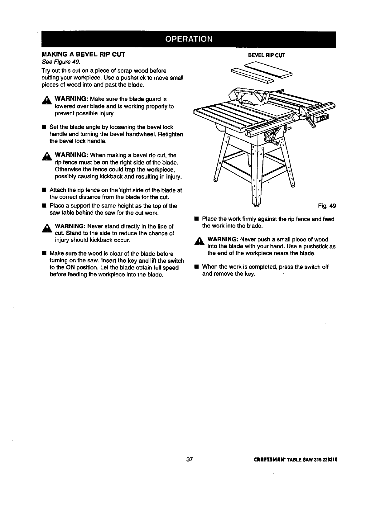
MAKINGA BEVELRIPCUT
See Figure 49.
Try out thiscut on a piece of scrap wood before
cuttingyour workpiece. Use a pushstickto move small
pieces of wood into and past the blade.
_, WARNING: Make sure the blade guard is
loweredover blade and is working propedy to
prevent possibleinjury.
•Set the blade angle by loosening the bevel lock
handle and turningthe bevel handwheel. Retighten
the bevel lock handle.
,_k WARNING: When making abevel rip cut, the
dp fence must be on the rightside of the blade.
Otherwise the fence could trap the workpiece,
possiblycausing kickbackand resultingin injury.
•Attachthe dp fence on the 'dghtside of the blade at
the correctdistancefrom the blade forthe cut.
•Place a supportthe same heightas the top of the
saw table behindthe saw for the cut work.
_1= WARNING: Never stand directly in the line of
cut. Stand to the side to reduce the chance of
injury should kickback occur.
•Make surethe woodis clear of the blade before
turningon the saw. Insert the key and liftthe switch
to the ON position.Let the blade obtainfull speed
beforefeeding the workpiece intothe blade.
BEVELRIPCUT
Fig. 49
•Place the workfirmly againstthe ripfence and feed
the work intothe blade.
,_ WARNING: Never push a small pieceof wood
into the blade with your hand. Use a pushstickas
the end of the workpiece nears the blade.
•When the work is completed, pressthe switchoff
and removethe key.
37 CRAFTSMAN"TABLESAW315.228310
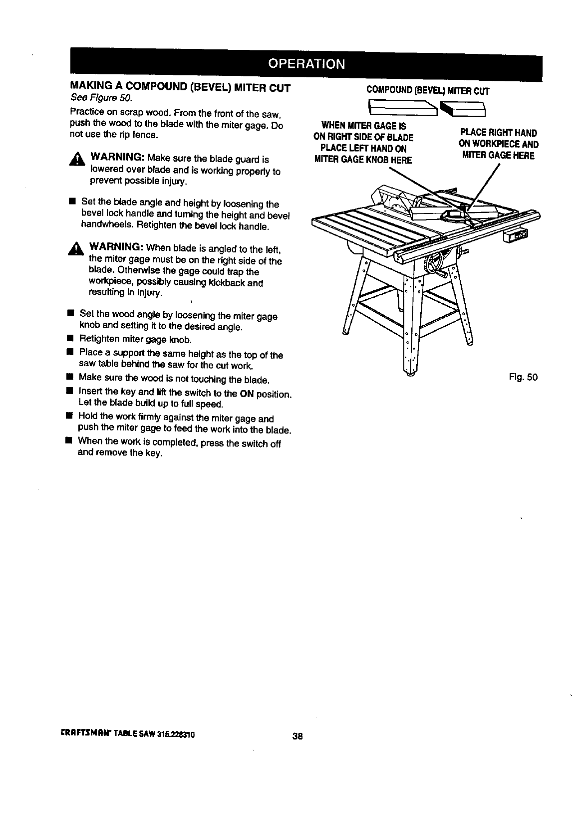
MAKING A COMPOUND (BEVEL) MITER CUT
Sea Figure 50.
Practice on scrap wood. From the front of the sew,
push the wood to the blade with the mitergage. Do
not use the rip fence.
WARNING: Make sure the blade guard is
lowered overblade and is workingproperlyto
prevent possible injury.
•Set the blade angle and heightby looseningthe
bevel lock handleand turningthe heightand bevel
handwheeis. Retightenthe bevel lockhandle.
,_ WARNING: When blade is angled to the left,
the miter gage must be onthe dghtside of the
blade. Otherwise the gage couldtrap the
workpiece, possiblycausingkickbackand
resultingin injury.
•Set the wood angle by loosening the miter gage
knob and settingit to the desiredangle.
•Retighten mitergage knob.
•Place a supportthe same heightas the top of the
saw table behind the saw for the cut work.
II Make surethe wood is nottouchingthe blade.
•Insert the kay and liftthe switchto the ON position.
Let the blade build upto full speed.
•Hold the work firmly against the mitergage and
push the miter gage to feed the workintothe blade.
•When the workis completed,press the switchoff
and removethe key.
COMPOUND(BEVEL)MITERCUT
WHENMITERGAGEIS
ONRIGHTSIDEOFBLADE
PLACELEFTHANDON
MITERGAGEKNOBHERE
PLACERIGHTHAND
ONWORK,PIECEAND
MITERGAGEHERE
Fig. 50
CRRFTSI4RN"TABLESAW315.228310 38
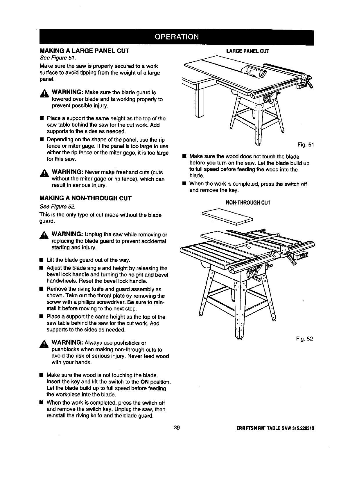
MAKING A LARGE PANEL CUT
See Figure 51.
Make sure the saw is properlysecured to awork
surfaceto avoid tippingfrom the weight of a large
panel.
_k WARNING: Make sure the blade guard is
lowered over blade and is working properly to
prevent possibleinjury.
•Place a supportthe same heightas the top of the
saw table behind the saw for the cut work. Add
supportsto the sides as needed.
•Dependingon the shape of the panel, use the rip
fence or miter gage. If the panel is too large to use
eitherthe ripfence or the mitergage, it is too large
for thissaw.
_l, WARNING: Never makp freehand cuts (cuts
withoutthe miter gage or ripfence), which can
result in seriousinjury.
MAKING A NON-THROUGH CUT
See Figure 52.
This is the only type of cut made withoutthe blade
guard.
,_, WARNING: Unplugthe saw while removingor
replacingthe blade guardto prevent accidental
startingand injury.
•Liftthe blade guard out of the way.
•Adjustthe blade angle and heightby releasingthe
bevel lockhandle and turningthe heightand bevel
handwheels. Reset the bevel lockhandle.
•Remove the rivingknife and guard assemblyas
shown.Take outthe throat plate by removingthe
screw witha phillipsscrewdriver.Be sure to rein-
stall it before movingto the next step.
•Place a supportthe same heightas the top of the
saw table behind the saw for the cut work. Add
supportsto the sidesas needed.
,_ WARNING: Always use pushsticksor
pushblockswhen making non-throughcuts to
avoid the riskof seriousinjury.Never feed wood
with your hands.
LARGEPANELCUT
Fig. 51
•Make surethe wood does nottouch the blade
before you turn on the saw. Let the blade buildup
to full speed before feeding the wood intothe
blade.
•When the work is completed,pressthe switchoff
and remove the key.
NON_HROUGHCUT
Fig. 52
•Make sure the wood is nottouchingthe blade.
Insert the key and liftthe switchto the ON position.
Let the blade build upto full speed before feeding
the workpiece intothe blade.
•When the workis completed, pressthe switchoff
and removethe switchkey. Unplugthe saw, then
reinstallthe rivingknifeand the blade guard.
39 CRIIFTSMRN" TABLE SAW 315,228310
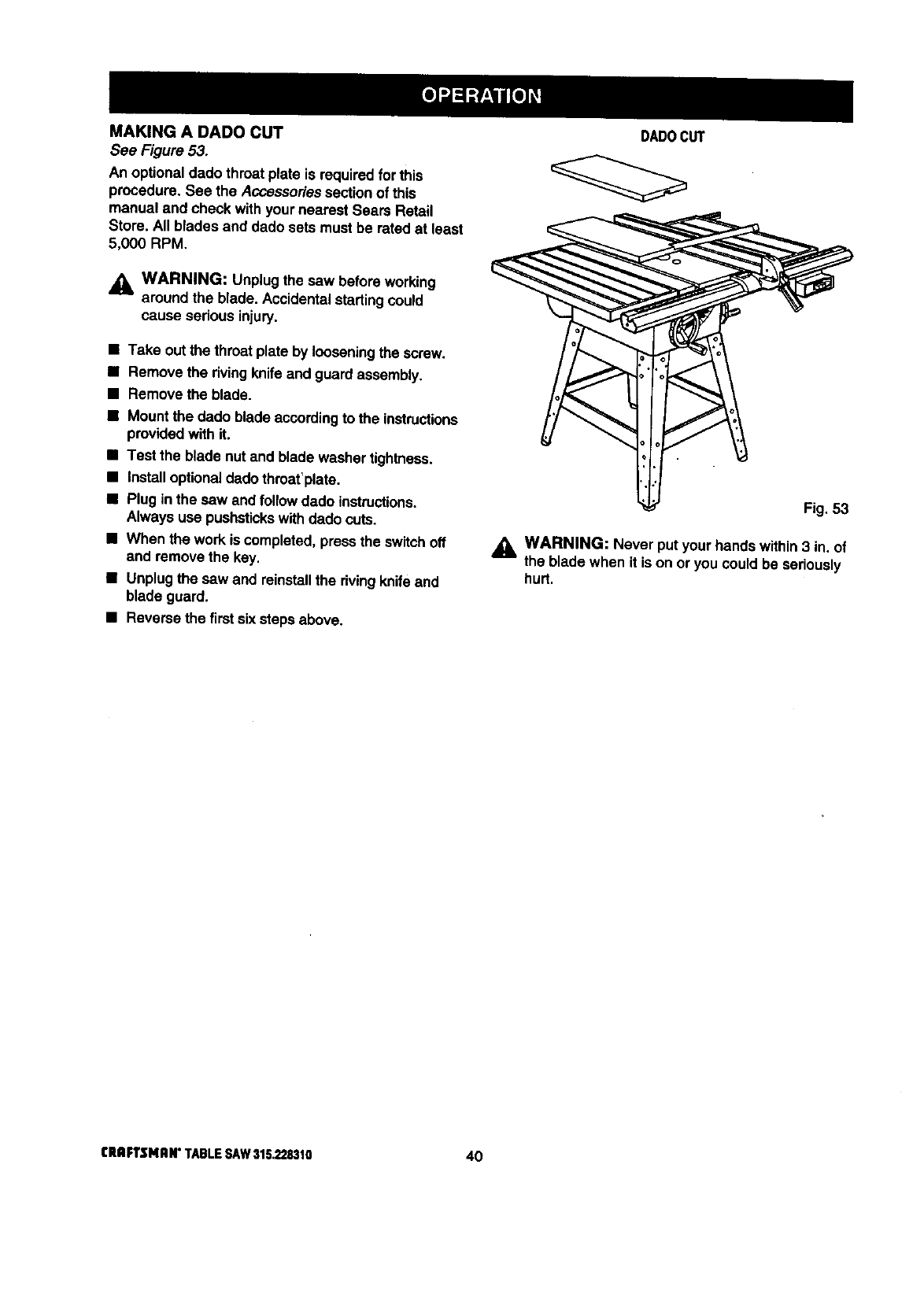
MAKING A DADO CUT
See Figure 53.
An optionaldado throat plate is requiredfor this
procedure. See the Accessoriessectionof this
manual and check withyour nearest Sears Retail
Store. All blades and dado sets must be ratedat least
5,000 RPM,
_L WARNING: Unplugthe saw before working
around the blade. Accidentalstartingcould
cause serious injury.
•Take outthe throatplate by looseningthe screw.
•Remove the rivingknife and guardassembly,
•Remove the blade.
•Mount the dado blade accordingto the instructions
providedwith it.
•Test the blade nutand blade washertightness.
•Installoptionaldado thmat'plate.
•Plug in the saw and follow dado instructions.
Always use pushstickswith dado cuts.
•When the workis completed, pressthe switchoff
and remove the key.
•Unplugthe saw and reinstallthe dvingknifeand
blade guard.
•Reverse the first six stepsabove.
DADO CUT
Fig, 53
WARNING: Never putyour hands within3 in. of
the blade when it is on or you could be seriously
hurt.
CRIIFTSMAN" TABLE SAW 315.228310 40

GENERAL MAINTENANCE
_k WARNING: When servicing,use only identical
Craftsman replacement pads. Use of any other
part may create ah_o.ardor cause product
damage.
WARNING: To prevent accidental startingthat
couldcause possibleserious personal injury,
turn off the saw, remove the switch key, and
unplugthe saw before working on the table saw.
•Remove sawdustfrom the rails, top surface, and
inside of saw frequently.
•Clean plastic partswith asoft damp cloth. Do not
use any strong solvents.
_, WARNING: Do not at any time let brake fluids,
gasoline, petroleum-based products,penetrating
oils, etc. contact plastic pads. They contain
chemicals that can damage, weaken or destroy
plastic.
•Pedodicallyclean the table, rails, and dp fence with
gum and pitch remover. Do not allow pitchto
accumulate onthe saw.
•Apply athin coat of paste wax to the table top so
the wood slides easily while cutting.
•Regularlycheck all nuts, bolts, screws, and belts
for tightnessand condition.Make sure the throat
plate is in goodcondition.
MOTOR /ELECTRICAL
•Frequently vacuum or blow out any sawdustfrom
the motor.
_l, WARNING: If the power cordis worn, cut, or
damaged in any way, have it replaced immedi-
ately by a qualifiedservice technicianat a Sears
store or repair center. Failure to do so could
result in serious personalinjury.
WARNING: To avoid fireor electrocution,
reassemble electric partswith only identical
Craftsman replacement pads. Reassemble
exactly as originallyassembled.
This saw has been lubricatedat the factory priorto
shipment.After extended use, you shouldinspect,
clean, and lubricatethe areas shown inthe drawing.
Clean before lubricatingwith a solvent recommended
for gumand pitch removal. Lubricate with SAE no. 20
or no. 30 engine oil.
See Figure 54.
•Table brackets.(a)
•Bevel handwheel rod threads and knuckle.(b)
•Height handwheelthreads and trunnion.(c)
41
B
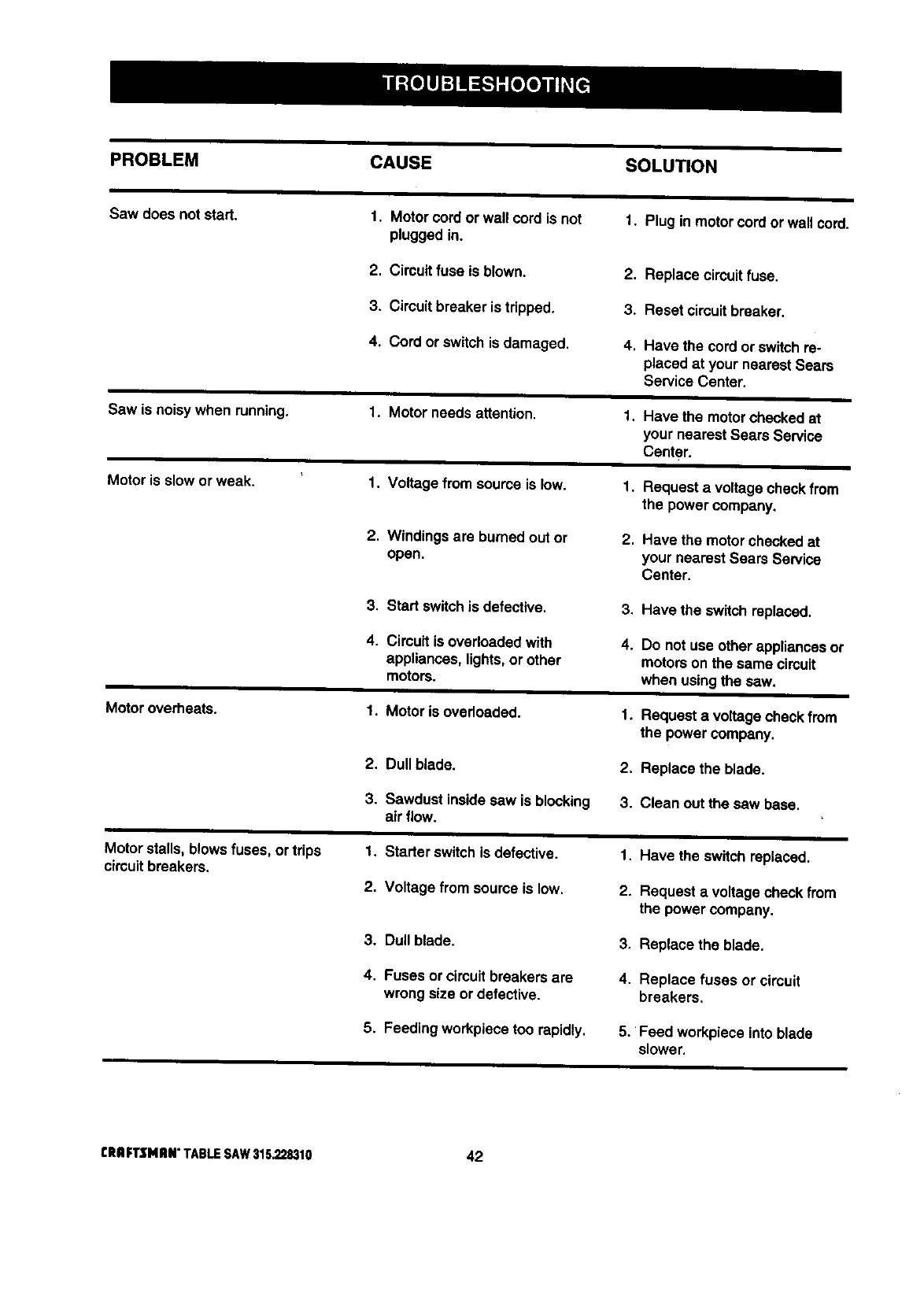
PROBLEM CAUSE SOLUTION
Sawdoesnotstart. 1. Motorcordorwallcordisnot 1. Pluginmotorcordorwallcord.
pluggedin.
2. Circuitfuseisblown.
3. Cimuitbreakeristripped.
4. Cordorswitchisdamaged.
Sawisnoisywhenrunning.
Motorissloworweak.
Motoroverheats.
Motorstalls,blowsfuses,ortrips
circuitbreakers.
1. Motor needs attention.
1. Voltage from source is low.
2. Windings are burnedout or
open.
3. Start switchis defective.
4. Circuit is overloaded with
appliances, lights, or other
motorS.
1. Motor is overloaded.
2. Du$$blade.
3. Sawdust insidesaw is blocking
air flow.
1. Starter switchis defective.
2. Voltage from source is low.
3. Dull blade.
4. Fuses or circuitbreakers are
wrong size or defective.
5, Feeding workplacetoo rapidly,
2. Replace circuitfuse.
3. Reset circuitbreaker.
4. Have the cord or switchre-
placed at your nearest Sears
Service Center.
1. Have the motor checkedat
your nearest Sears Service
Center.
1. Request a voltage check from
the power company.
2, Have the motor checkedat
your nearest Sears Service
Center.
3, Have the switch replaced.
4. Do not use other appliances or
motors on the same circuit
when usingthe saw.
1. Request a voltage check from
the power company.
2. Replace the blade.
3. Clean out the saw base.
1. Have the switch replaced.
2. Request a voltage check from
the power company.
3. Replace the blade.
4. Replace fuses or circuit
breakers.
5. Feed work,piece into blade
slower.
CRIIFTSNRN"TABLESAW315.228310 42
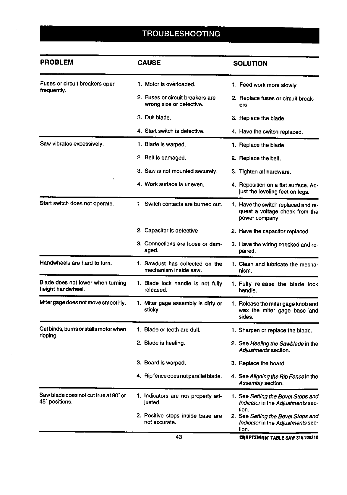
PROBLEM CAUSE SOLUTION
Fuses or circuitbreakers open
frequently. 1. Motor is overloaded.
2. Fuses or circuitbreakers are
wrongsize or defective.
1. Feed work more slowly.
2. Replace fuses or circuit break-
ers,
3. Dull blade. 3. Replace the blade.
Saw vibrates excessively.
4. Start switchis defective.
1. Blade is warped.
4. Have the switchreplaced.
1. Replace the blade.
2. Belt is damaged, 2. Replace the belt.
3. Saw is not mountedsecurely. 3, Tighten all hardware.
4. Work surface is uneven. 4. Repositionon a flat surface. Ad-
justthe leveling feet on legs.
Start switchdoes not operate. 1. Switch contactsare burned out. 1. Have the switchreplaced andre-
quest a voltage check from the
power company.
2. Capacitor is defective 2. Have the capacitor replaced.
3. Connectionsare loose or dam- 3. Have the widngchecked and re-
aged. paired.
Handwheels are hard to turn. 1. Sawdust has collected on the 1. Clean and lubricate the mecha-
mechanism insidesaw. nism.
Blade does not lower when turning
heighthandwheel. 1. Blade lock handle is not fully 1. Fully release the blade lock
released, handle.
Mitergage doesnotmovesmoothly. 1. Miter gage assembly is dirty or 1. Release the mitergage knoband
sticky, wax the miter gage base _and
sides.
Cutbinds,bumsorstallsmotorwhen
ripping. 1. Blade orteeth are dull,
2. Blade is heeling.
1. Sharpen or replace the blade.
2. See Hee/ingtheSawbladeinthe
Adjustmentssection.
3. Board is warped. 3. Replace the board.
4. Ripfencedoesnotparallelblade. 4. SeeAligningtheRipFenceinthe
Assembly section.
Saw bladedoes notcut trueat 90"or 1.
45" positions.
2.
Indicators are not properly ad-
justed.
Positive stops inside base are
notaccurate.
1. See Setting the Bevel Stops and
Indicatorinthe Adjustmentssec-
tion.
2. See Setting the Bevel Stops and
Indicatorinthe Adjustmentssec-
tion.
43 CRAFTSMRN"TABLESAW315.228310
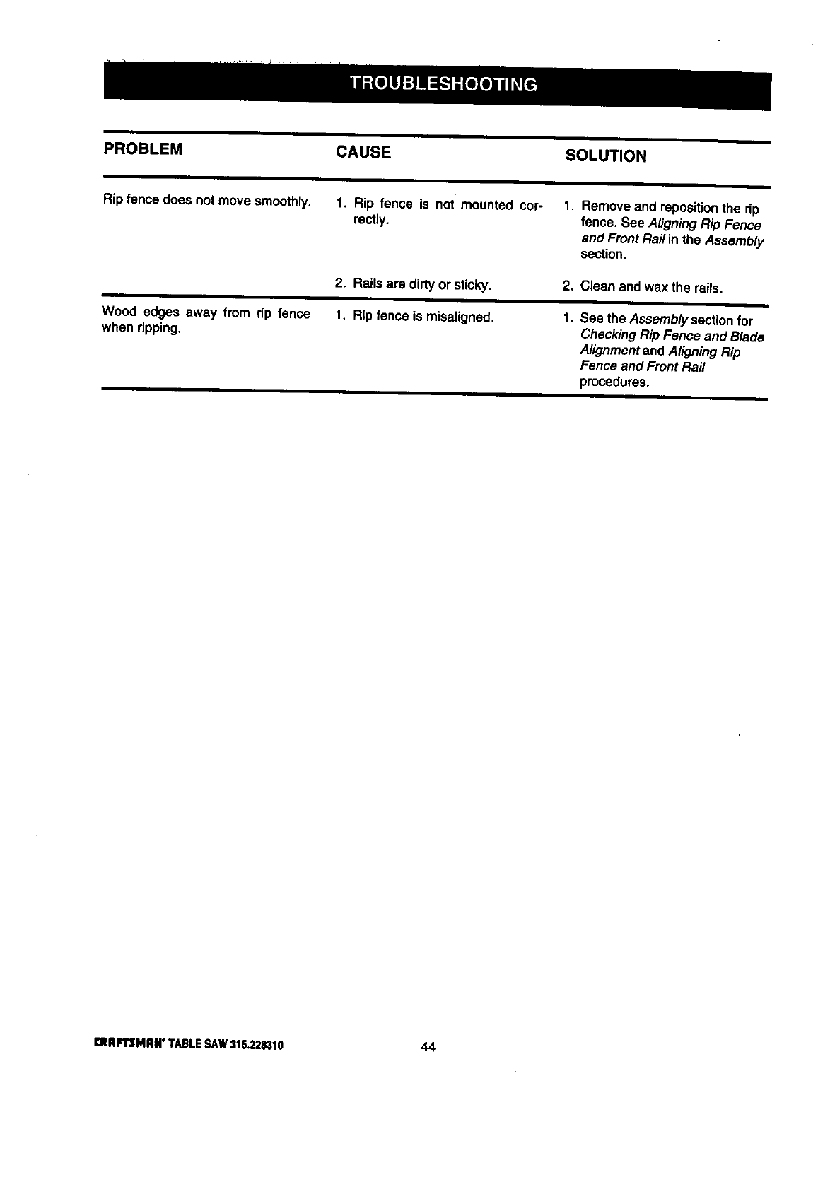
PROBLEM CAUSE SOLUTION
Rip fence does not move smoothly. 1. Rip fence is not mounted cor-
rectly.
1. Remove and repositionthe rip
fence. See AligningRip Fence
and Front Rail in the Assembly
section.
2. Rails are dirty or sticky. 2. Clean and wax the mils.
Wood edges away from rip fence
when ripping. 1. Rip fence is misaligned. 1. See the Assembly section for
Checking Rip Fence and Blade
Alignmentand AligningRip
Fence and Front Rail
procedures.
CRIIFTSMlU4"TABLESAW3_G.22834,0 44

45 CRRFTSMAN" TABLE SAW 315.228310
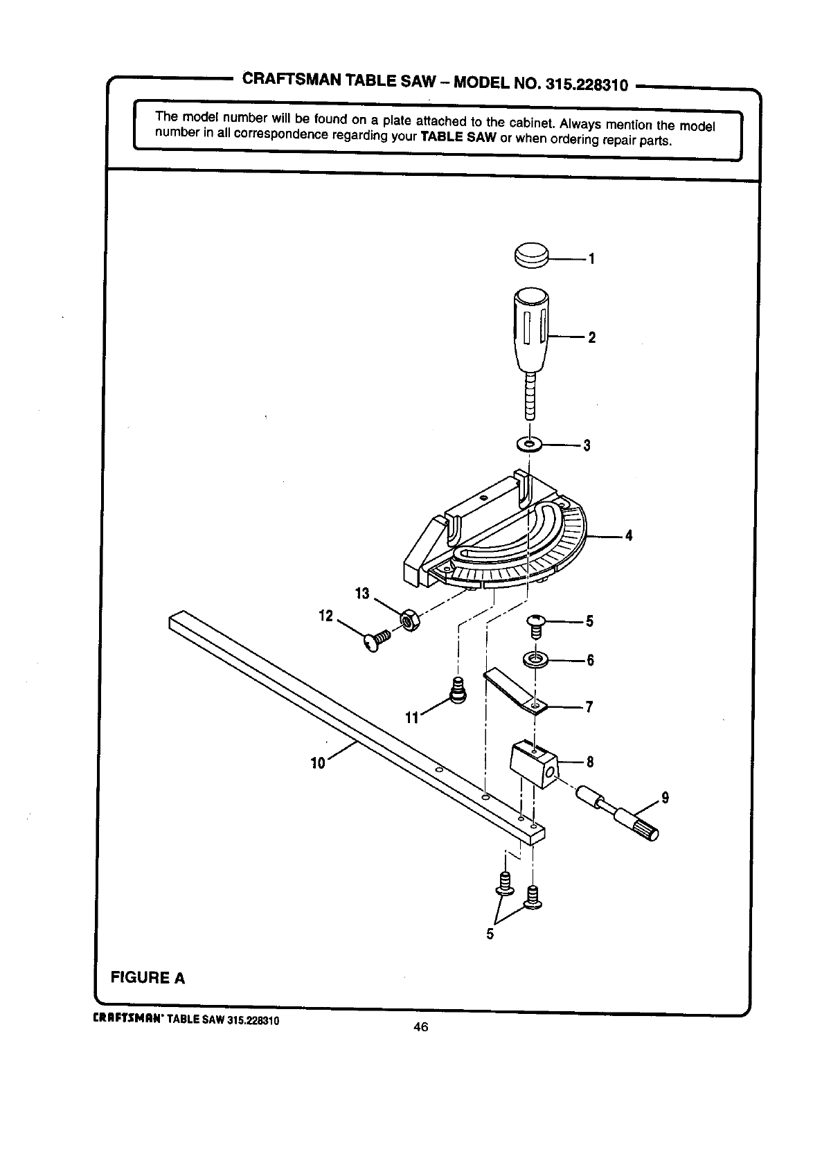
CRAFTSMAN TABLE SAW - MODEL NO. 315.228310
IThe model number will be found on a plate attached to the cabinet. Always mention the model !
numberin all correspondenceregarding your TABLE SAW or when ordering repairpads. I
12
FIGURE A
CRIIFTSMRN" TABLE SAW 315.228310 46
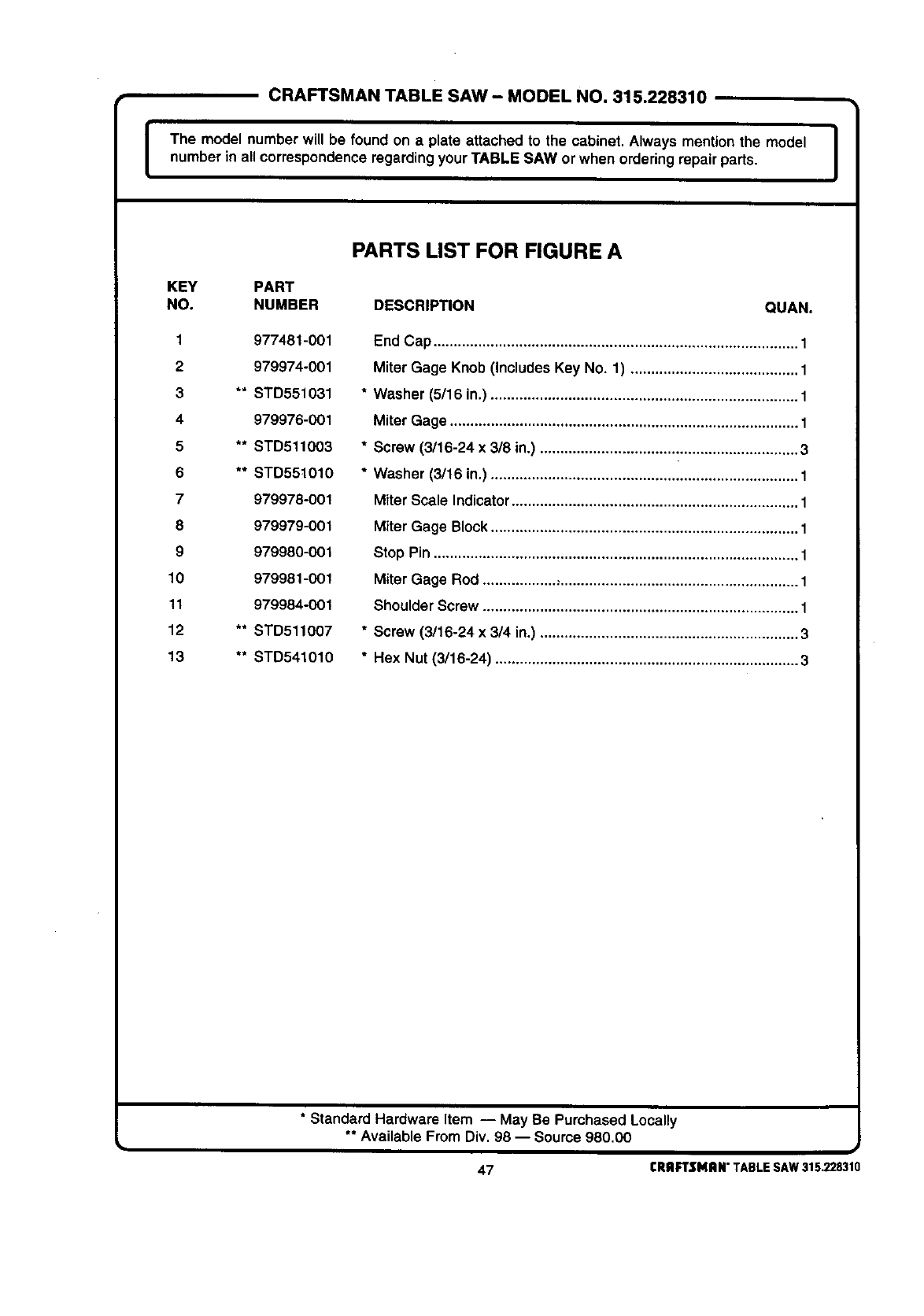
CRAFTSMAN TABLE SAW -MODEL NO. 315.228310
I The model number will be found on a plate attached to the cabinet. Always mention the model I
number in all correspondenceregardingyour TABLE SAW or when ordering repair parts. I
PARTS LIST FOR FIGURE A
KEY PART
NO. NUMBER DESCRIPTION QUAN.
1977481-001
2 979974-001
3 ** STD551031
4979976-001
5 ** STD511O03
6 ** STD55t010
7 979978-001
8 979979-001
9 979980-001
10 979981-001
11 979984-001
12 ** STD511007
13 ** STD541010
End Cap ......................................................................................... 1
Miter Gage Knob (Includes Key No. 1) ......................................... 1
* Washer (5/16 in.) ........................................................................... 1
Miter Gage ..................................................................................... 1
* Screw (3/16-24 x 3/8 in.) ............................................................... 3
*Washer (3/16 in.) ........................................................................... 1
Miter Scale Indicator...................................................................... 1
Miter Gage Block........................................................................... 1
Stop Pin ......................................................................................... 1
Miter Gage Rod ...................,.......................................................... 1
Shoulder Screw ............................................................................. 1
* Screw (3/16-24 x 3/4 in.) ............................................................... 3
*Hex Nut (3/16-24) .......................................................................... 3
•Standard Hardware Item -- May Be Purchased Locally
** Available From Div. 98 -- Source 980.00
47 CRAFTSMAN"TABLESAW315.228310
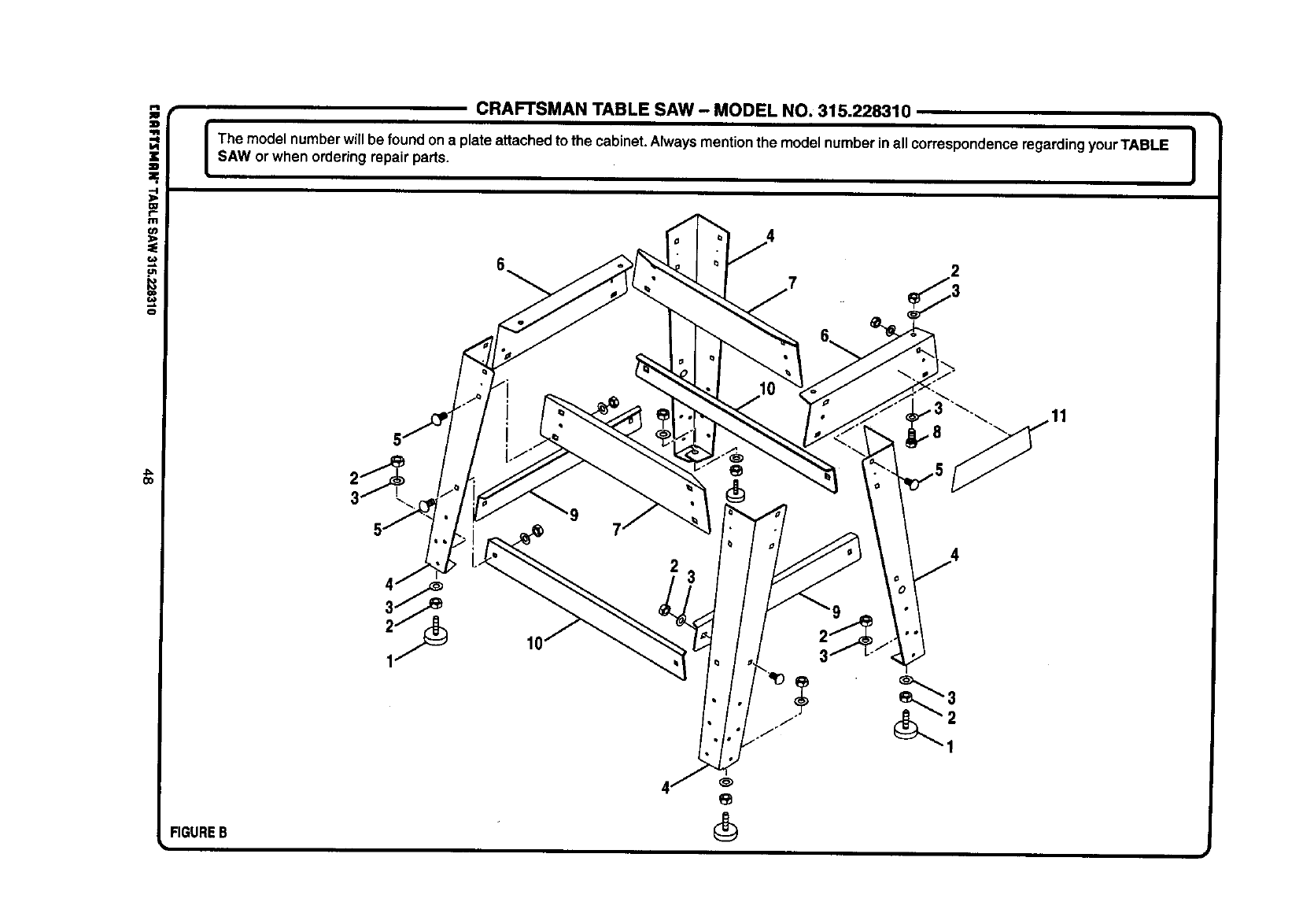
i
.-I
:D.
l:U
m
(n
o
FIGUREB
k
CRAFTSMAN TABLE SAW - MODEL NO. 315.228310
The model numberwill be foundona plate attachedto the cabinet.Alwaysmentionthe model numberinall correspondenceregardingyour TABLE i
SAW orwhen orderingrepair parts. J
3
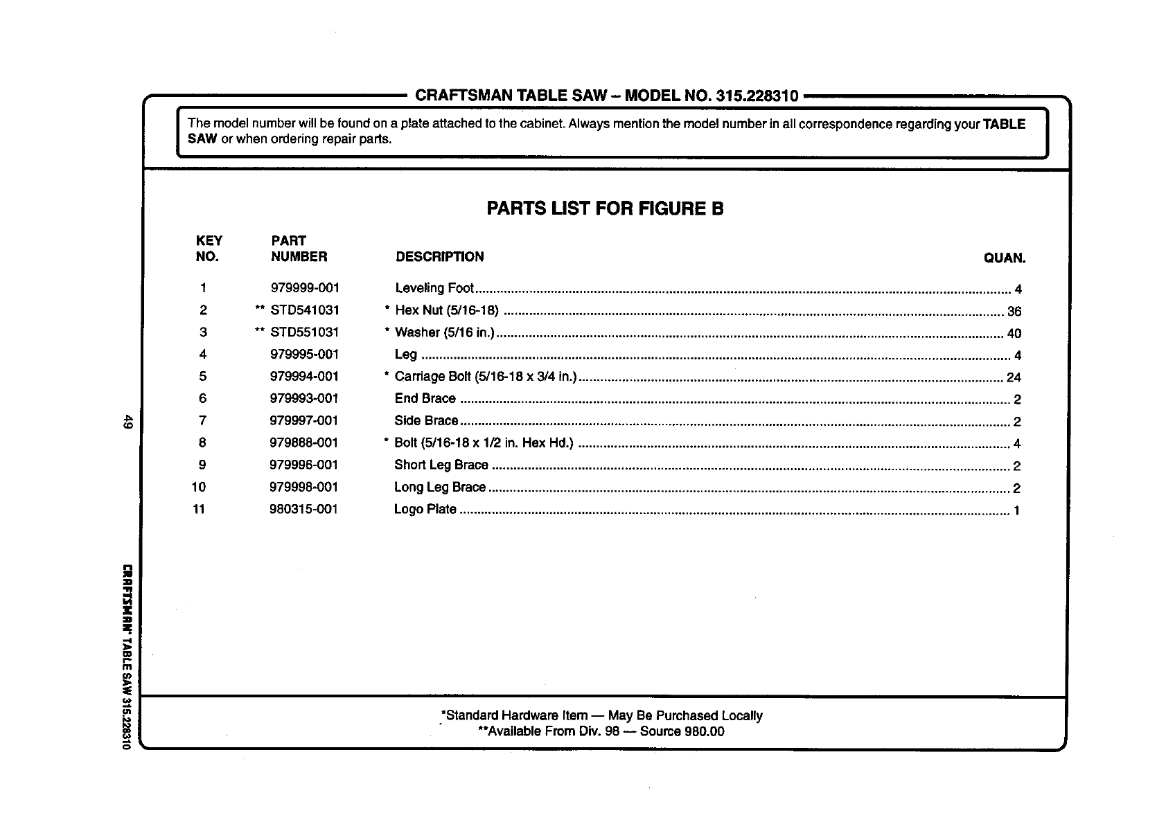
CRAFTSMANTABLE SAW- MODELNO.315.228310
Ihe model numberwill be foundona plate attached to the cabinet.Alwaysmentionthe model numberinall correspondenceregardingyour TABLE J
SAW or when orderingrepair parts. I
(o
m
r
f11
=E
,e.
PARTS LIST FOR FIGURE B
KEY PART
NO. NUMBER DESCRIPTION QUAN.
1 979999-001
2** STD541031
3** STD551031
4 979995-001
5 979994-001
6 979993-001
7 979997-001
8 979888-001
9 979996-001
10 979998-001
11 980315-001
Leveling Foot..................................................................................................................................................... 4
*Hex Nut (5/16-18) ........................................................................................................................................... 36
* Washer (5/16 in.)............................................................................................................................................. 40
Leg .................................................................................................................................................................... 4
* Carriage Bolt(5/16-18 x 3/4 in.)...................................................................................................................... 24
End Brace ......................................................................................................................................................... 2
Side Brace......................................................................................................................................................... 2
* Bolt(5/16-18 x 1/2 in. Hex Hd.) ........................................................................................................................ 4
Short Leg Brace ................................................................................................................................................ 2
Long Leg Brace................................................................................................................................................. 2
Logo Plate ......................................................................................................................................................... 1
*Standard Hardware Item -- May Be Purchased Locally
**Available From Div. 98 -- Source 980.00
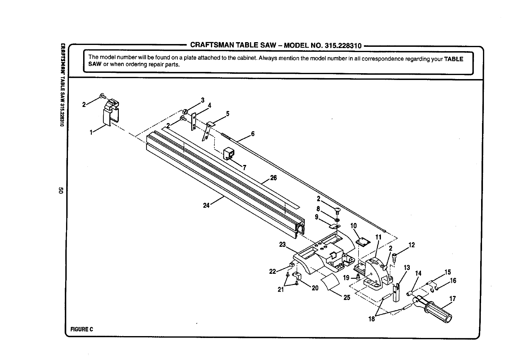
i
¢,m
o
O1
O
CRAFTSMAN TABLE SAW - MODEL NO. 315.228310
Ihe model numberwillbe foundon a plateattached to the cabinet.Always mentionthe model numberin all correspondenceregardingyour TABLE !
SAW or when orderingrepair parts. I
24'
21
10
11
25
13 14
17
FIGUREC
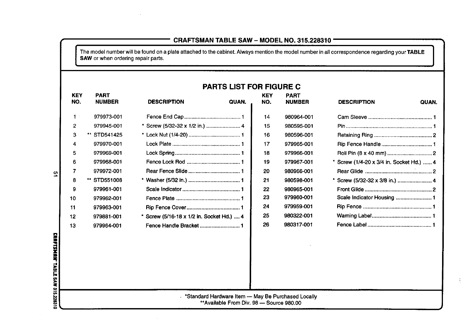
i
al
CRAFTSMAN TABLE SAW- MODEL NO, 315.228310
IThe model numberwillbe foundon aplate attached to the cabinet. Always mention the model number in all correspondence regarding your TABLE |
I
SAW or when ordering repair parts. I
PARTS LIST FOR FIGURE C
KEY PART KEY PART
NO. NUMBER DESCRIPTION QUAN. NO. NUMBER DESCRIPTION QUAN.
1 979973-001
2 979945-001
3 ** STD541425
4 979970-001
5 979969-001
6 979968-001
7979972-001
8 ** STD551008
9 979961-001
10 979962-001
11 979963-001
12 979881-001
13 979964-001
Fence End Cap ...................................... 1
* Screw (5/32-32 x 1/2 in.) ....................... 4
* Lock Nut (1/4-20) ................................... 1
Lock Plate .............................................. 1
Lock Spdng ............................................ 1
Fence Lock Rod .................................... 1
Rear Fence Slide ................................... 1
* Washer (5/32 in.) ................................... 1
Scale Indicator ....................................... 1
Fence Plate ........................................... 1
Rip Fence Cover .................................... 1
* Screw (5/16-18 x 1/2 in. Socket Hd.) .... 4
Fence Handle Bracket ........................... 1
14 980964-001
15 980596-001
16 980596-001
17 979965-001
18 979966-001
19 979967-001
20 980966-001
21 980598-001
22 980965-001
23 979960-001
24 979959-001
25 980322-001
26 980317-001
Cam Sleeve ........................................... 1
Pin .......................................................... 1
Retaining Ring ....................................... 2
Rip Fence Handle .................................. 1
Roll Pin (8 x 40 mm) .............................. 2
Screw (1/4-20 x 3/4 in. Socket Hal.) ...... 4
Rear Glide ............................................. 2
Screw (5/32-32 x 3/8 in.) ....................... 4
Front Glide ............................................. 2
Scale Indicator Housing ........................ 1
Rip Fence .............................................. 1
Waming Label ........................................ 1
Fence Label ........................................... 1
•*Standard Hardware Item -- May Be Purchased Locally
**Available From Div. 98 -- Source 980.00
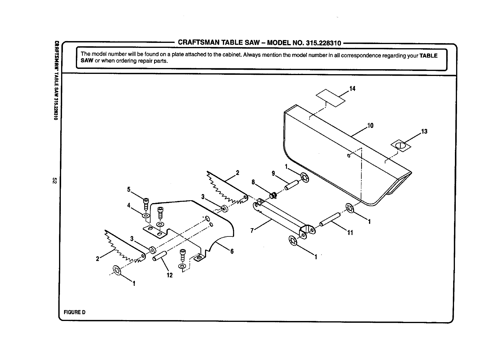
i
O1
I%1
CRAFTSMAN TABLE SAW - MODEL NO. 315.228310
IThe model numberwill be found ona plateattachedto the cabinet.Always mentionthe modelnumberin allcorrespondenceregardingyour TABLE I
SAW or when ordering repair parts. !
FIGURED
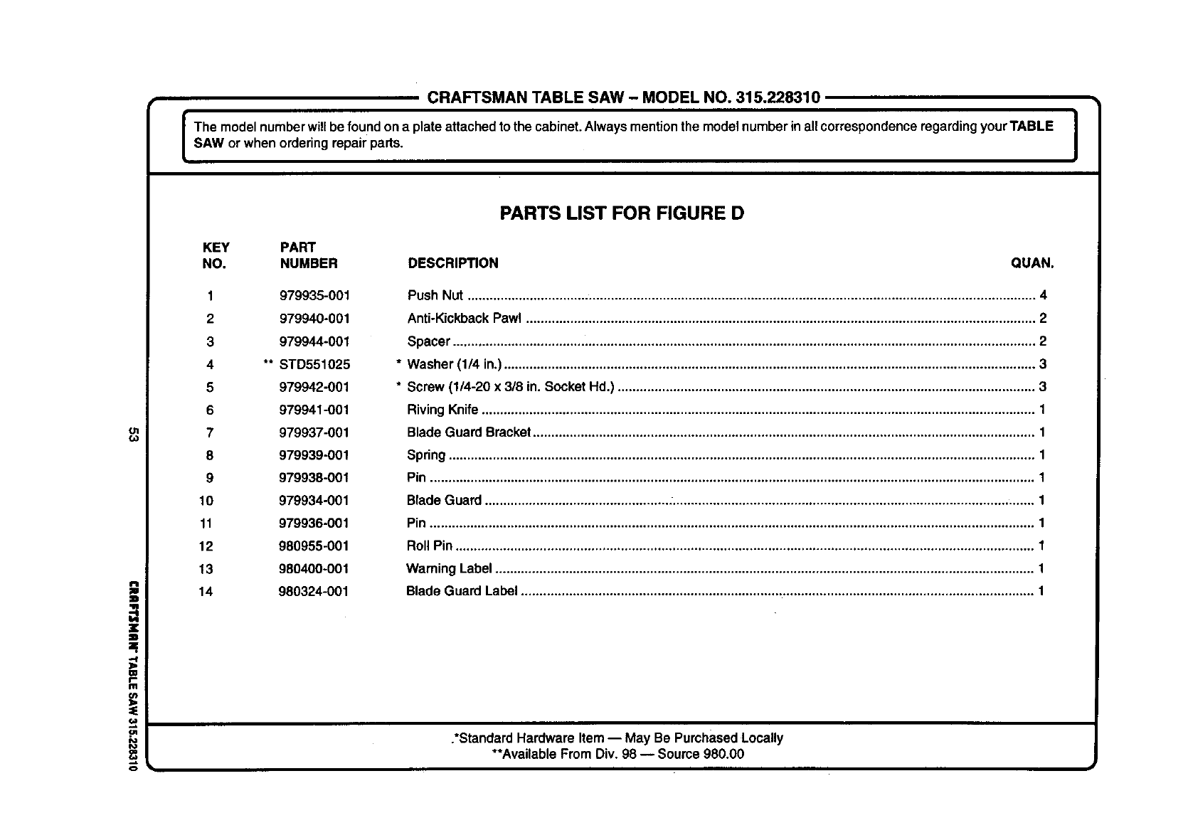
CRAFTSMAN TABLE SAW- MODEL NO. 315.228310
The modelnumberwillbe foundona plateattached tothe cabinet.Always mentionthe modelnumberin allcorrespondenceregardingyourTABLE J
SAW or when orderingrepair parts. I
ol
€.o
=W
W
111
o
PARTS LIST FOR FIGURE D
KEY PART
NO. NUMBER DESCRIPTION QUAN.
1 979935-001
2 979940-001
3 979944-001
4** STD551025
5 979942-001
6 979941-001
7 979937-001
8 979939-001
9 979938-001
10 979934-001
11 979936-001
12 980955-001
13 980400-001
14 980324-001
Push Nut .......................................................................................................................................................... 4
Anti-KickbackPawl .......................................................................................................................................... 2
Spacer .............................................................................................................................................................. 2
Washer (1/4 in.)................................................................................................................................................ 3
Screw (1/4-20 x 3/8 in. Socket Hd.) ................................................................................................................. 3
Riving Knife...................................................................................................................................................... 1
Blade Guard Bracket........................................................................................................................................ 1
Spring............................................................................................................................................................... 1
Pin .................................................................................................................................................................... 1
Blade Guard .................................................. :.................................................................................................. 1
Pin .................................................................................................................................................................... 1
RollPin ............................................................................................................................................................. 1
Warning Label .................................................................................................................................................. 1
Blade Guard Label ........................................................................................................................................... 1
.*StandardHardware Item-- May Be Pumhased Locally
**Available From Div. 98 -- Source 980.00

ol
4==
CRAFTSMAN TABLE SAW - MODEL NO. 315.228310
The modelnumberwill be foundona plate attachedto the cabinet.Always mentionthe modelnumberin allcorrespondenceregardingyourTABLE I
SAW orwhen orderingrepair parts. I
11
FIGUREE
iI
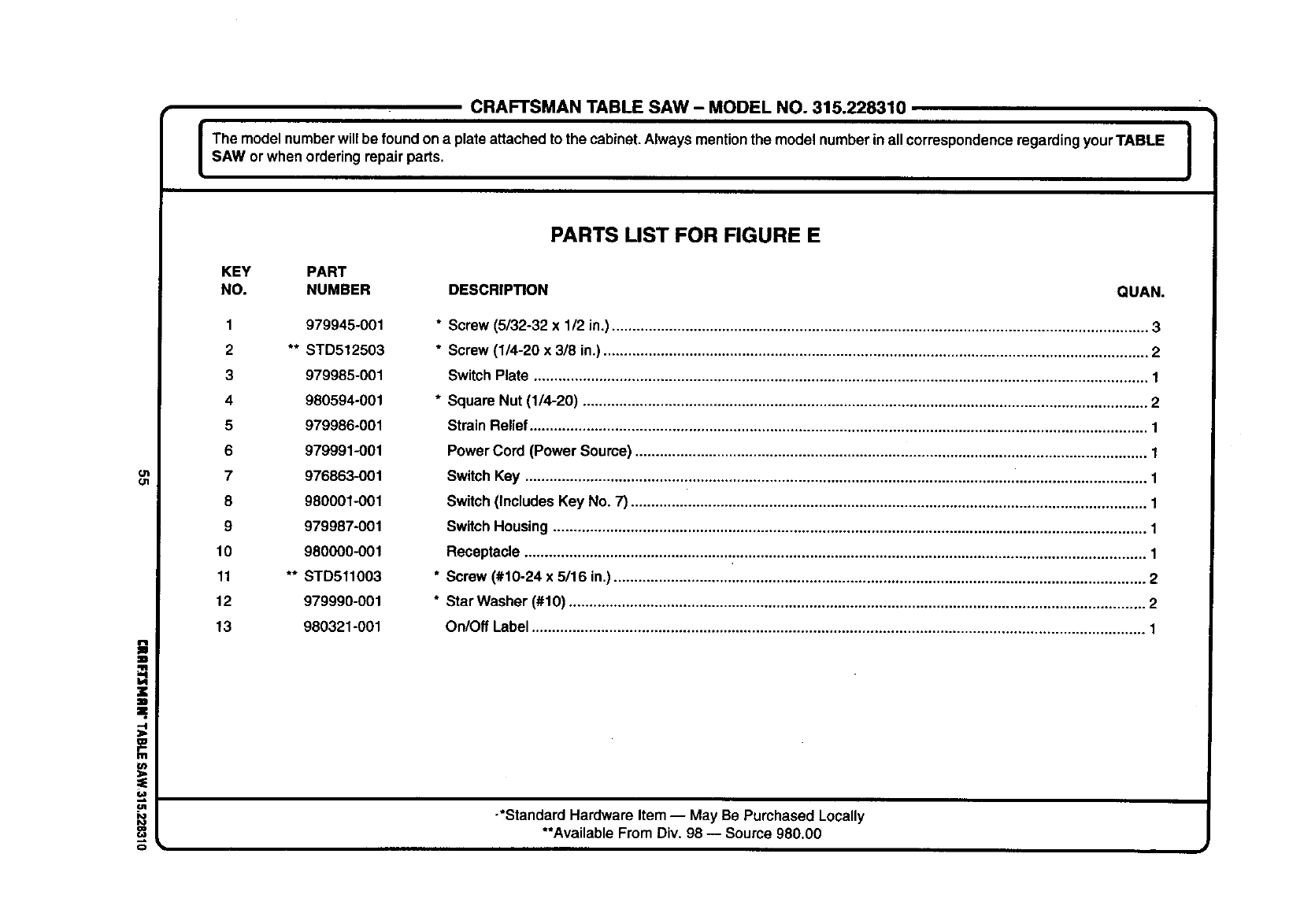
CRAFTSMAN TABLE SAW - MODEL NO. 315.228310
I The model number willbe foundon a plate attachedto the cabinet.Always mentionthe model numberinall correspondenceregardingyour TABLE I
I
SAW or when orderingrepair parts. I
ot
O1
=.
tJt
o
PARTS LIST FOR FIGURE E
KEY PART
NO. NUMBER DESCRIPTION QUAN.
1979945-001
2 ** STD512503
3 979985-001
4980594-001
5 979986-001
6 979991-001
7 976863-001
8 980001-001
9 979987-001
10 980000-001
11 ** STD511003
12 979990-001
13 980321-001
*Screw (5/32-32 x1/2 in.)................................................................................................................................... 3
*Screw (1/4-20 x 3/8 in.)..................................................................................................................................... 2
Switch Plate ...................................................................................................................................................... 1
* Square Nut (1/4-20) .......................................................................................................................................... 2
Strain Relief....................................................................................................................................................... 1
PowerCord (Power Source) ............................................................................................................................. 1
SwitchKey ........................................................................................................................................................ 1
Switch(Includes Key No. 7) .............................................................................................................................. 1
SwitchHousing ................................................................................................................................................. 1
Receptacle ........................................................................................................................................................ 1
* Screw (#10-24 x 5/16 in.).................................................................................................................................. 2
* Star Washer (#10) ............................................................................................................................................. 2
On/Off Label ...................................................................................................................................................... 1
-*Standard Hardware Item -- May Be Purchased Locally
**Available From Div. 98 -- Source 980.00
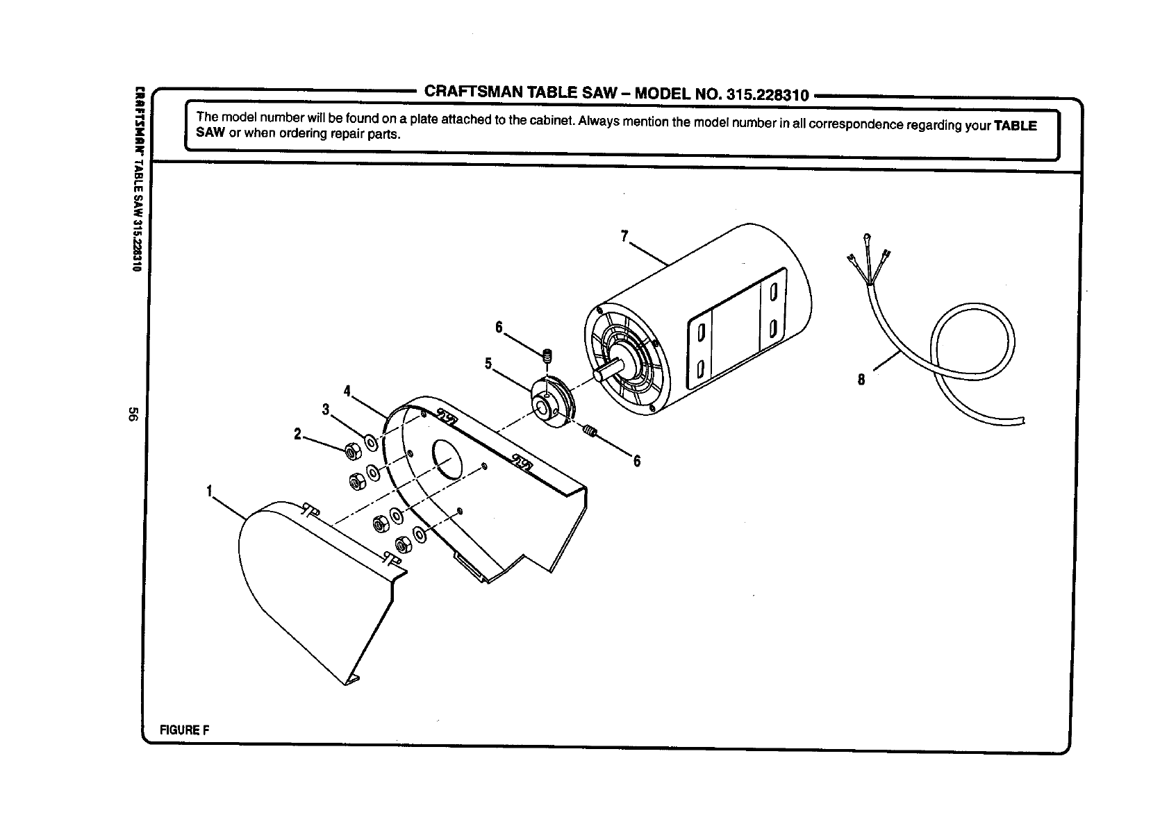
Ol
Cb
CRAFTSMAN TABLE SAW - MODEL NO. 315.228310
I The model numberwillbe foundon aplateattachedto the cabinet.Always mention the model numberin allcorrespondenceregarding your TABLE |
I
SAW or when orderingrepair parts. I
6
FIGUREF
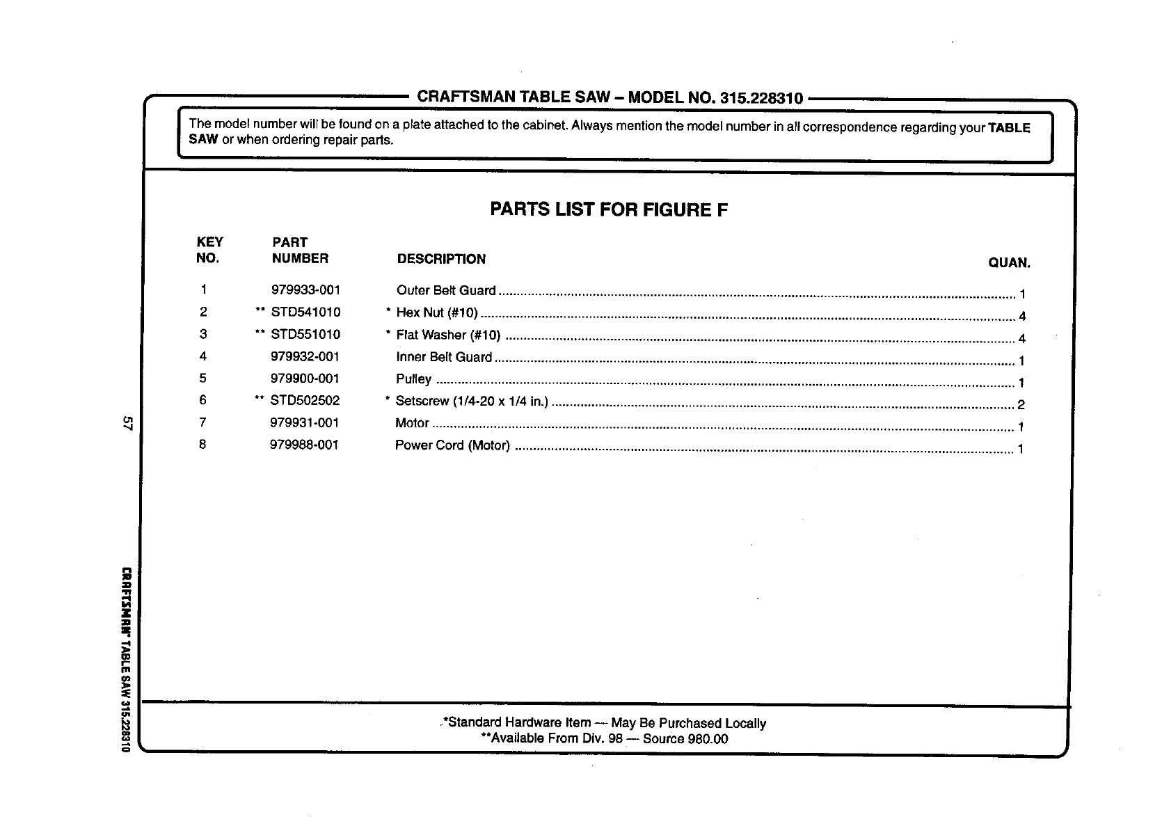
CRAFTSMAN TABLE SAW- MODEL NO. 315.228310
em°0ew °'° ° e °0enum °°c°0°0 0Is,worw ono°e00
ol
W
f,.
m
P_
KEY PART
NO. NUMBER DESCRIPTION
1
2
3
4
5
6
7
8
979933-001
** STD541010
** STD551010
979932-001
979900-001
** STD502502
979931-001
979988-001
PARTS LIST FOR FIGURE F
QUAN.
Outer Belt Guard ............................................................................................................................................... 1
* Hex Nut (#10) .................................................................................................................................................... 4
*Flat Washer (#10) ............................................................................................................................................. 4
Inner Belt Guard ................................................................................................................................................ 1
Pulley ................................................................................................................................................................ 1
* Setscrew (1/4-20 x 1/4 in.) ................................................................................................................................ 2
Motor ................................................................................................................................................................. 1
Power Cord (Motor) .......................................................................................................................................... 1
,*Standard Hardware Item -- May Be Purchased Locally
**Available From Div. 98 -- Source 980.00
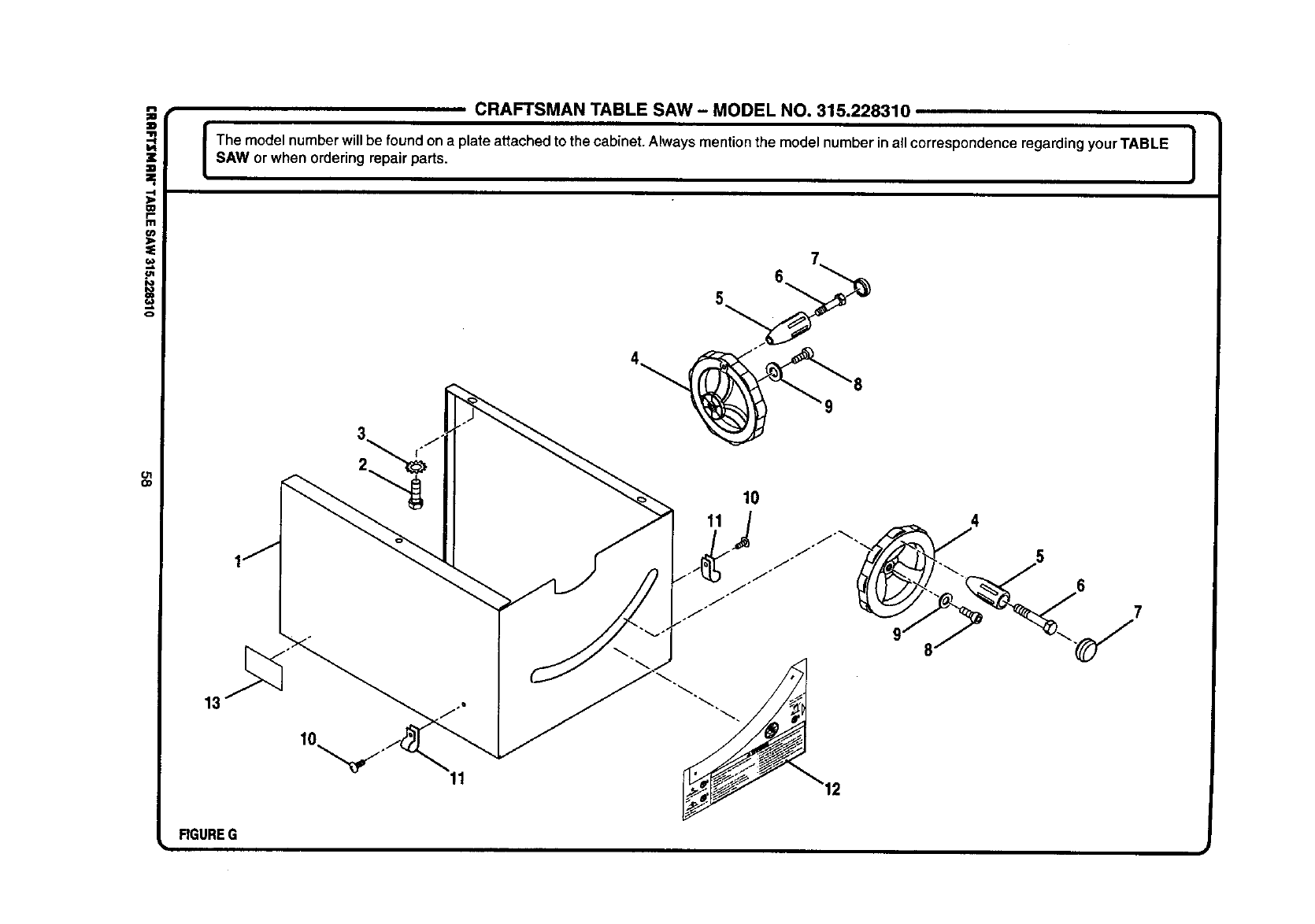
i
o
Ol
O1
CRAFTSMAN TABLE SAW - MODEL NO. 315.228310
The model number willbe found on a plate attached to the cabinet. Always mention the model number inall correspondence regarding your TABLE |
SAW or when ordering repair parts. I
17
FIGUREG
11
6
5
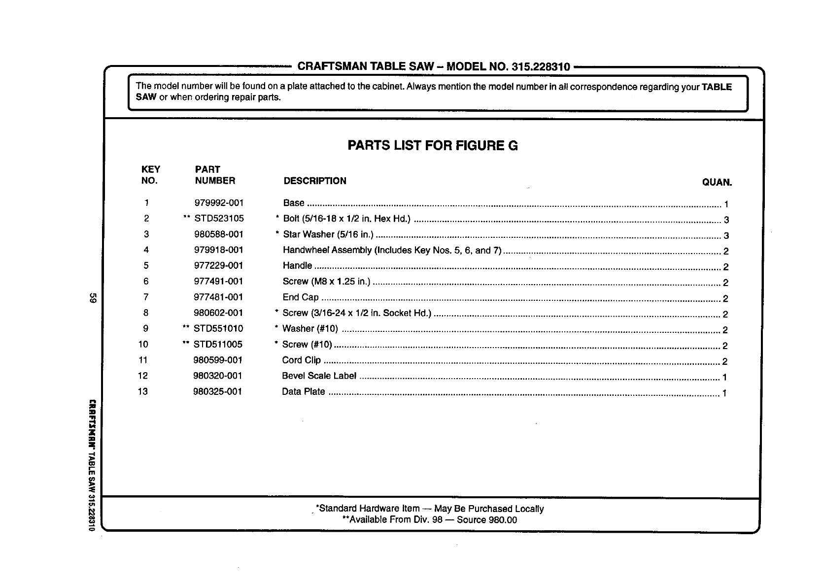
CRAFTSMANTABLE SAW- MODELNO.315.228310
The model number will be foundon a plate attached to the cabinet.Always mentionthe model numberin allcorrespondenceregardingyourTABLE |
SAW or when orderingrepair parts. I
Ol
(D
i
=.
CD
r"
Ill
PARTS LIST FOR FIGURE G
KEY PART
NO. NUMBER DESCRIPTION QUAN.
1 979992-001
2** STD523105
3980588-001
4979918-001
5 977229-001
6 977491-001
7 977481-001
8 980602-001
9 ** STD551010
10 ** STD511005
11 980599-001
12 980320-001
13 980325-001
Base .................................................................................................................................................................. 1
* Bolt (5/16-18 x 1/2 in. Hex Hd.) ........................................................................................................................ 3
* Star Washer (5/16 in.) ....................................................................................................................................... 3
Handwheel Assembly (Includes Key Nos. 5, 6, and 7) ..................................................................................... 2
Handle ............................................................................................................................................................... 2
Screw (M8 x 1.25 in.) ........................................................................................................................................ 2
End Cap ............................................................................................................................................................ 2
* Screw (3/16-24 x 1/2 in. Socket Hd.) ................................................................................................................ 2
* Washer (#10) .................................................................................................................................................... 2
* Screw (#10) ....................................................................................................................................................... 2
Cord Clip ........................................................................................................................................................... 2
Bevel Scale Label ............................................................................................................................................. 1
Data Plate ......................................................................................................................................................... 1
•*Standard Hardware Item -- May Be Purchased Locally
**Available From Div. 98 -- Source 980.00
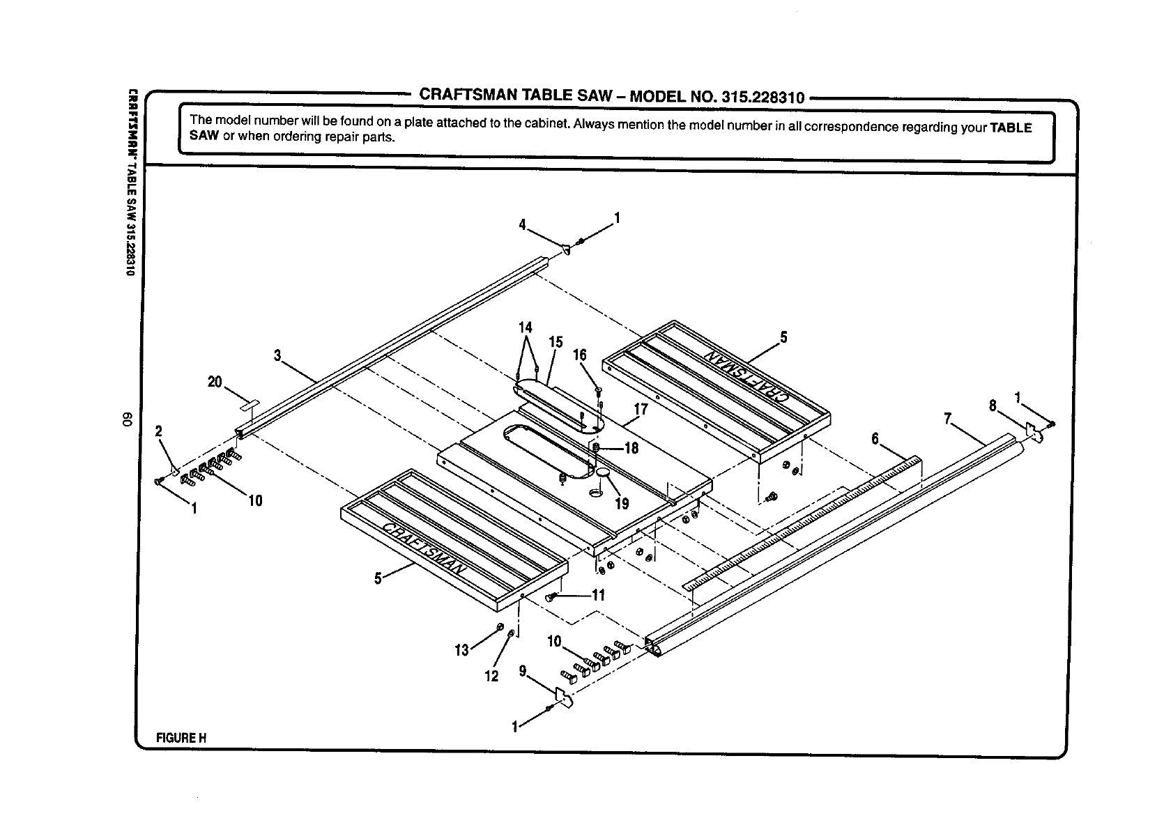
!
¢3
o_
o
CRAFTSMAN TABLE SAW- MODEL NO. 315.228310
I Them_de_numberwi'_bef_und_nap_ateattachedt_thecabinet_A_waysmenti_nthem_de_numberina__c_rresp_ndencer_gardingy_urTABLE_sAwor when orderingrepair parts.
2
FIGUREH i
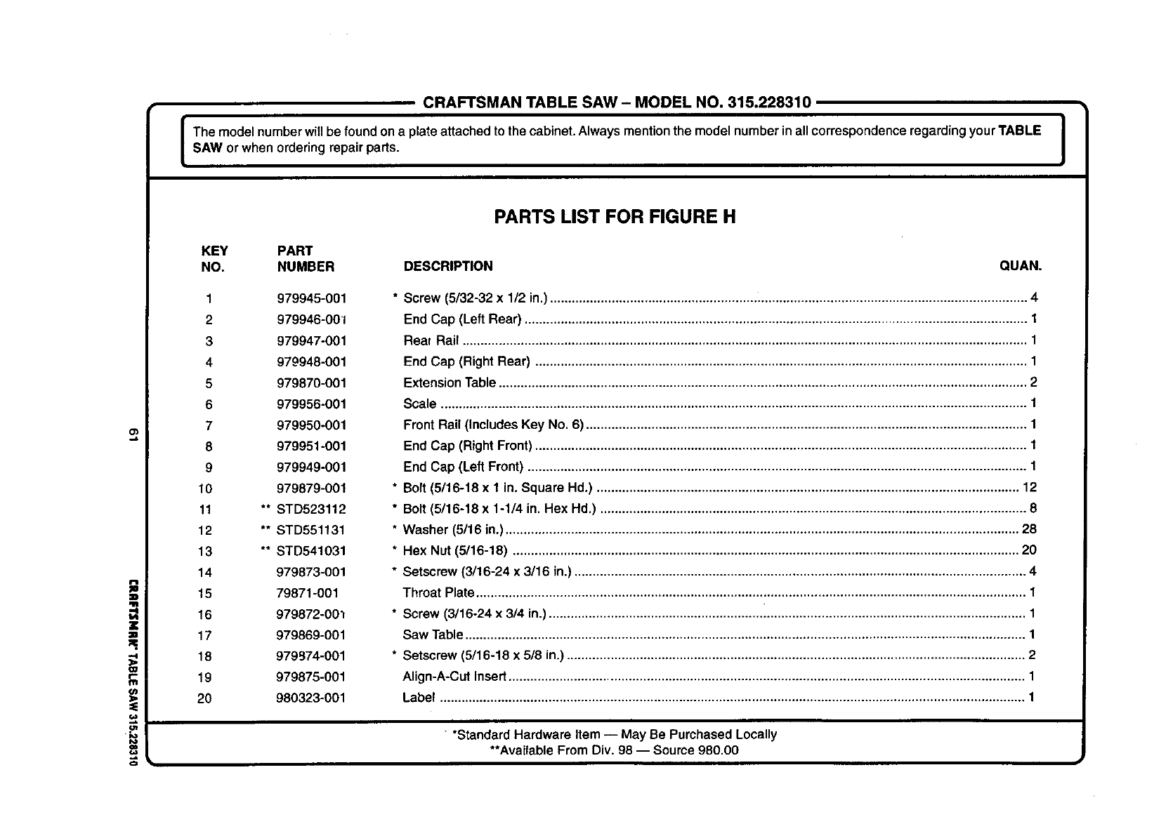
CRAFTSMAN TABLE SAW- MODEL NO. 315.228310
The model numberwillbe found on a plateattachedto the cabinet.Always mentionthe modelnumberin allcorrespondenceregardingyour TABLE i
SAW or when orderingrepair parts. I
i
"4
O_
=E
f.w
io
o
PARTS LIST FOR FIGURE H
KEY PART
NO. NUMBER DESCRIPTION QUAN.
1979945-001
2979946-001
3 979947-001
4 979948-001
5 979870-001
6 979956-001
7 979950-001
8 979951-001
9 979949-001
10 979879-001
11 ** STD523112
12 ** STD551131
13 ** STD541031
14 979873-001
15 79871-001
16 979872-00_
17 979869-001
18 979974-001
19 979875-001
20 980323-001
* Screw (5/32-32 x 1/2 in.)................................................................................................................................... 4
End Cap (Left Rear) .......................................................................................................................................... 1
Real Rail ........................................................................................................................................................... 1
End Cap (Right Rear) ....................................................................................................................................... 1
Extension Table ................................................................................................................................................. 2
Scale ................................................................................................................................................................. 1
Front Rail (Includes Key No. 6) ......................................................................................................................... 1
End Cap (Right Front) ....................................................................................................................................... 1
End Cap (Left Front) ......................................................................................................................................... 1
* Bolt (5/16-18 x 1 in. Square Hd.) .................................................................................................................... 12
* Bolt (5/16-18 x 1-1/4 in. Hex Hd.) ..................................................................................................................... 8
* Washer (5/16 in.) ............................................................................................................................................. 28
* Hex Nut (5/16-18) ........................................................................................................................................... 20
* Setscrew (3/16-24 x 3/16 in.) ............................................................................................................................ 4
Throat Plate ....................................................................................................................................................... 1
* Screw (3/16-24 x 3/4 in.) ........................................................... i....................................................................... 1
Saw Table .......................................................................................................................................................... 1
* Setscrew (5/16-18 x 5/8 in.) .............................................................................................................................. 2
Align-A-Cut Insert .............................................................................................................................................. 1
Label ................................................................................................................................................................. 1
• *Standard Hardware Item -- May Be Purchased Locally
**Available From Div. 98 -- Source 980.00
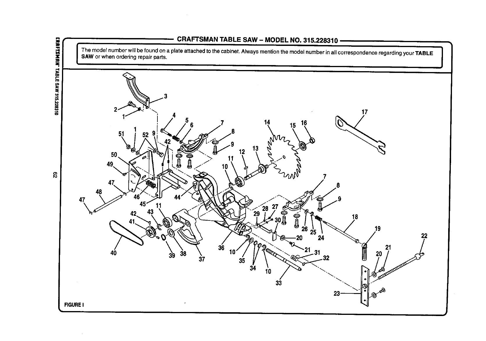
i
(J1
,e.
o
o')
Po
CRAFTSMAN TABLE SAW - MODEL NO. 315.228310
Ihe model numberwill be foundon a plate attachedto the cabinet.Alwaysmentionthe model numberinall correspondenceregardingyour TABLE I
SAW or when ordering repairparts. I
50
1
51
49,
47
48
47
12
1t15 16
7
17
40 36
38 37 35
34 10
33
IB
19 22
FIGURE I
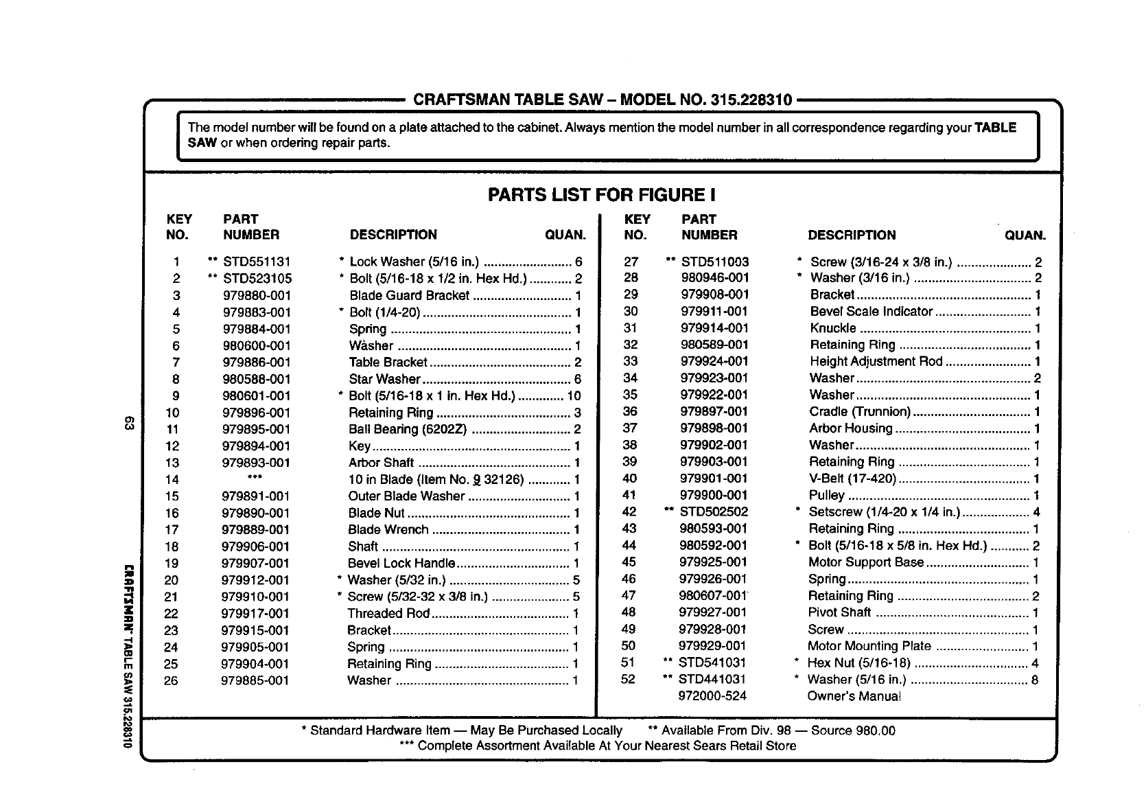
CRAFTSMAN TABLE SAW - MODEL NO. 315.228310
I The model numberwillbe foundon a plate attachedto the cabinet.Alwaysmentionthe modelnumber inall correspondenceregarding yourTABLE I
I
SAW or when ordedngrepair pads. I
o)
z
II
z
-4
OI
r-
I11
u)
Io
€o
o
KEY PART
NO. NUMBER DESCRIPTION QUAN.
1** STD551131
2 ** STD523105
3 979880-001
4 979883-001
5 979884-001
6 980600-001
7979886-001
8 980588-001
9 980601-001
10 979896-001
11 979895-001
12 979894-001
13 979893-001
14 ***
15 979891-001
16 979890-001
17 979889-001
18 979906-001
19 979907-001
20 979912-001
21 979910-001
22 979917-001
23 979915-001
24 979905-001
25 979904-001
26 979885-001
PARTS LIST FOR FIGURE I
KEY PART
* Lock Washer (5/16 in.) ......................... 6
* Bolt (5/16-18 x 1/2 in. Hex Hd.) ............ 2
Blade Guard Bracket ............................ 1
* Bolt (1/4-20) .......................................... 1
Spdng ................................................... 1
Washer ................................................. 1
Table Bracket ........................................ 2
Star Washer .......................................... 6
* Bolt (5/16-18 x 1 in. Hex Hd.) ............. 10
Retaining Ring ...................................... 3
Ball Beadng (8202Z) ............................ 2
Key ........................................................ 1
Arbor Shaft ........................................... 1
10 in Blade (Item No. 9 32126) ............ 1
Outer Blade Washer ............................. 1
Blade Nut .............................................. 1
Blade Wrench ....................................... 1
Shaft ..................................................... 1
Bevel Lock Handle ................................ 1
* Washer (5/32 in.) .................................. 5
* Screw (5/32-32 x 3/8 in.) ...................... 5
Threaded Rod ....................................... 1
Bracket .................................................. 1
Spring ................................................... 1
Retaining Ring ...................................... 1
Washer ................................................. 1
NO. NUMBER DESCRIPTION QUAN.
27 ** STD511003
28 980946-001
29 979908-001
30 979911-001
31 979914-001
32 980589-001
33 979924-001
34 979923-001
35 979922-001
36 979897-001
37 979898-001
38 979902-001
39 979903-001
40 979901-001
41 979900-001
42 ** STDS02502
43 980593-001
44 980592-001
45 979925-001
46 979926-001
47 980607-001
48 979927-001
49 979928-001
50 979929-001
51 ** STD541031
62 ** STD441031
972000-524
* Screw (3/16-24 x 3/8 in.) ..................... 2
* Washer (3/16 in.) ................................. 2
Bracket ................................................. 1
Bevel Scale Indicator ........................... 1
Knuckle ................................................ 1
Retaining Ring ..................................... 1
Height Adjustment Rod ........................ 1
Washer ................................................. 2
Washer ................................................. 1
Cradle (Trunnion)................................. 1
Arbor Housing ...................................... 1
Washer ................................................. 1
Retaining Ring ..................................... 1
V-Belt (17-420) ..................................... 1
Pulley ................................................... 1
* Setscrew (1/4-20 x 1/4 in.) ................... 4
Retaining Ring ..................................... 1
* Bolt (5/16-18 x 5/8 in. Hex Hd.) ........... 2
Motor Support Base ............................. 1
Spring ................................................... 1
Retaining Ring ..................................... 2
Pivot Shaft ........................................... 1
Screw ................................................... 1
Motor Mounting Plate .......................... 1
* Hex Nut (5/16-18) ................................ 4
* Washer (5/16 in.) ................................. 8
Owner's Manual
* Standard Hardware Item -- May Be PurchasedLocally ** Available From Div. 98 -- Source 980.00
*** Complete AssortmentAvailableAt Your Nearest Sears Retail Store

For in-home major brand repair service:
Call 24 hours a day, 7days a week
1-800-4-MY-Home s" (1-800-469-4663)
Para pedir servicio de reparaci6n a domicilio - 1-800-676-5811
In Canada for all your service and parts needs call _ 1-800-665-4455
Au Canada pour tout le service ou les pi_ces
For the repair or replacement parts you need:
Call 7 am - 7 pro, 7 days aweek
1-800-366-PART (1-800-366-7278)
Para ordenar piezas con entrega a domicilio - 1-800-659-7084
For the location of a Sears Parts and Repair Center in your area:
Call 24 hours a day, 7 days a week
1-800-488-1222
For information on purchasing a Sears Maintenance Agreement
or to inquire about an existing Agreement:
Call 9 am - 5 pro, Monday - Saturday
1-800-827-6655
I
The Service Side of Sears"
