Craftsman 486 248381 Operators Manual
486248381 ef2a07a4-254c-4391-8abe-6ed59324ad9a Craftsman Snow Blower 486.248381 User Guide |
2015-01-05
: Craftsman Craftsman-486-248381-Operators-Manual-161175 craftsman-486-248381-operators-manual-161175 craftsman pdf
Open the PDF directly: View PDF ![]() .
.
Page Count: 40
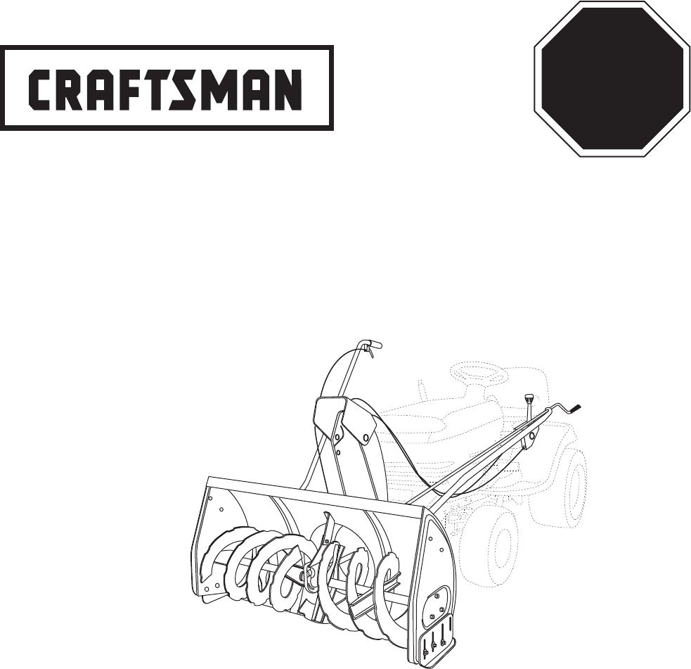
Operator's Manual
TRACTOR ATTACHMENT
Model No. 486.248381
42"- 2 STAGE SNOW THROWER
®
PRINTED IN U.S.A. FORM NO. 40242 (REV. 12/13/07)
Sears, Roebuck and Co., Hoffman Estates, IL 60179 U.S.A.
www.sears.com/craftsman
CAUTION:
Before using this product, read
this manual and follow all Safety
Rules and Operating Instructions.
• Safety
• Assembly
• Operation
• Maintenance
• Parts
STOP
DO NOT RETURN TO STORE
For Missing Parts or Assembly
Questions Call 1-866-576-8388
2
TABLE OF CONTENTS
MODEL NUMBER: 486.248381
SERIAL NUMBER: __________________
DATE OF PURCHASE: __________________
The model number and serial numbers will be found on a
decal attached to the snow thrower.
You should record both the serial number and the date of
purchase and keep in a safe place for future reference.
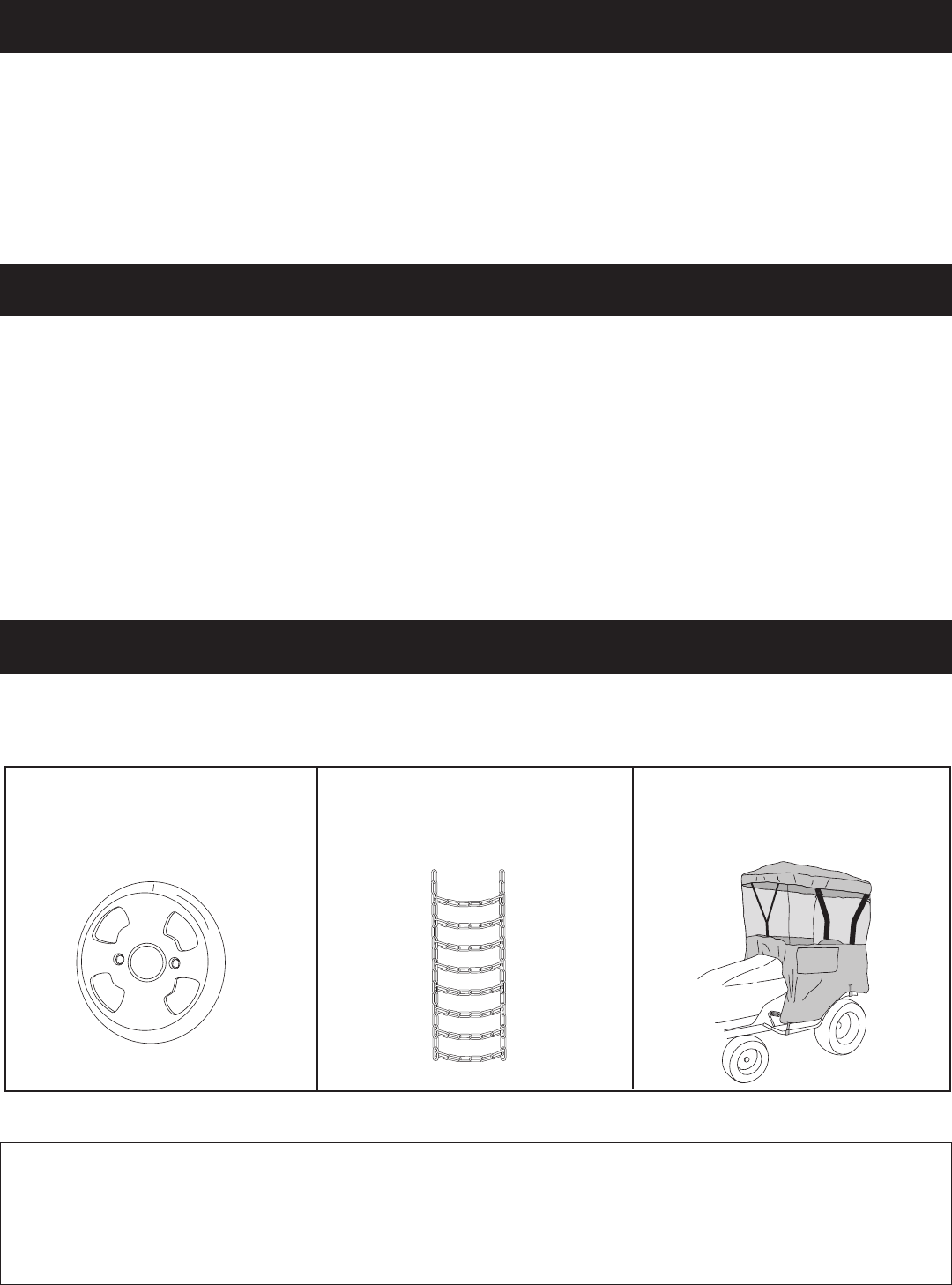
ACCESSORIES AND ATTACHMENTS
WHEEL WEIGHT
Theseandotheraccessoriesarerecommendedforusewithyourunit.Call1-800-4-MY-HOME®tondoutiftheyareavailable.
Ifavailable,theymaybepurchasedatmostCraftsmanoutletsorbycalling1-800-4-MY-HOME®.
WARRANTY
ONE YEAR FULL WARRANTY
When operated and maintained according to the instructions supplied with it, if this Snowthrower fails due to a defect in
material or workmanship within one year from the date of purchase, call 1-800-4-MY-HOME® to arrange for free repair (or
replacementifrepairprovesimpossible).
If this product is used for commercial or rental purposes, this warranty applies for only 90 days from the date of purchase.
Thiswarrantygivesyouspeciclegalrights,andyoumayalsohaveotherrightswhichvaryfromstatetostate.
Sears, Roebuck and Co., D817WA, Hoffman Estates, IL 60179
TIRE CHAINS
SERVICE AND ADJUSTMENTS ...................................29
STORAGE .....................................................................30
TROUBLESHOOTING ...................................................30
REPAIR PARTS ILLUSTRATION ........................34,36,38
REPAIR PARTS LIST...........................................35,37,38
SLOPE GUIDE ..............................................................39
PARTS ORDERING/SERVICE ...................BACK COVER
ACCESSORIES ...............................................................2
SAFETY RULES ..............................................................3
FULL SIZE HARDWARE CHART ....................................4
CARTON CONTENTS .....................................................6
ASSEMBLY ......................................................................7
OPERATION ..................................................................27
MAINTENANCE ............................................................28
SNOW CAB
71-24276

3
SAFETY
Any power equipment can cause injury if operated improperly or if the user does not understand how to operate the equipment.
Exercise caution at all times, when using power equipment.
• Readthisowner'smanualcarefullyandknowhowto
operate your snow thrower and how to stop the unit
and disengage the controls quickly.
• Neverallowchildrentooperatetheequipment.
• Neverallowadultstooperatetheequipmentwithout
proper instruction.
• Keeptheareaofoperationclearofallpersons,
especially small children, and pets.
• Thoroughlyinspecttheareawheretheequipmentis
tobeusedandremovealldoormats,sleds,boards,
wires and other foreign objects.
• Disengageallclutchesandshiftintoneutralbefore
starting engine.
• Donotoperateequipmentwithoutwearingadequate
winter outer garments.
• Wearsubstantialfootwearwhichwillprotectfeetand
improvefootingonslipperysurfaces.
• Checkfuelbeforestartingtheengine.Donotremove
thefuelcaporllthefueltankwhiletheengine
isrunningorhot.Donotllthefueltankindoors.
Gasolineisanextremelyammablefuel.
• Makesurethesnowthrowerheightisadjustedto
clear the type surface it will be used on.
• Donotusethesnowthrowerwithouttherearweight
attached to the tractor.
• Nevermakeanyadjustmentswhiletheengineis
running.
• Alwayswearsafetyglassesoreyeshieldduring
operation or while performing adjustment or repair.
• Donotplacehandsorfeetnearrotatingparts.Keep
clear of the discharge opening at all times.
• Useextremecautionwhenoperatingonorcrossing
gravelsurfaces.
• Donotcarrypassengers.
• Afterstrikingaforeignobject,stoptheengine,remove
the wire from the spark plug and then thoroughly
inspect the snow thrower for damage. Repair any
damage before restarting and operating the snow
thrower.
• Ifthesnowthrowerstartstovibrateabnormally,stop
the engine immediately and check for the cause.
Vibration is generally a warning of trouble.
• Stoptheenginewheneveryouleavetheoperating
position, before unclogging the snow thrower or
making any adjustments or inspections.
• Takeallpossibleprecautionswhenleavingtheunit
unattended.Disengagetheattachmentclutchleveror
switch, lower the snow thrower, shift into neutral, set
theparkingbrake,stoptheengineandremovethe
key.
• Whencleaning,repairingorinspecting,makecertain
allmovingpartshavestopped.Disconnectthespark
plugwireandkeepitawayfromtheplugtoprevent
accidental starting.
• Donotrunengineindoorsexceptwhentransporting
the snow thrower in or out of the building. Open the
outside doors. Exhaust fumes are dangerous.
• Donotclearsnowacrossthefaceofslopes.Exercise
extreme caution when changing direction on slopes.
Do not attempt to clear steep slopes. Refer to the
slope guide on page 39 of this manual.
• Neveroperatethesnowthrowerwithoutguards,
platesorothersafetyprotectiondevicesinplace.
• Neveroperatethesnowthrowernearglass
enclosures, automobiles, window wells, drop offs
etc. without proper adjustment of the snow thrower
discharge angle.
• Neverdirectdischargeatbystandersorallowanyone
in front of the snow thrower.
• Neverrunthesnowthrowerintomaterialathigh
speeds.
• Donotoverloadthemachinecapacitybyattempting
to clear snow at too fast a rate.
• Neveroperatethemachineathightransportspeed
on slippery surfaces. Look behind and use care when
backing up.
• Watchfortrafcandstayalertwhencrossingor
operating near roadways.
• Disengagepowertothesnowthrowerwhen
transporting or when not in use.
• Useonlyattachmentsandaccessoriesapprovedby
the manufacturer of the snow thrower (such as wheel
weights, counter weights, cabs etc.)
• Neveroperatethesnowthrowerwithoutgoodvisibility
or light.
Look for this symbol to point out important safety precautions. It means — Attention!! Become
alert!! Your safety is involved.
4
G
ADF
KLMNO
S
HI
BB
Y
C
CC
E
AA
PU
W,X
V
DD
QQ
KK
R
EE
FF II
HH
GG
NOT SHOWN ACTUAL SIZE
SHOWN ACTUAL SIZE
JJ
J
Q
PP
LL MM
OO
Z
T
NN
B
RR
TT
SS
HARDWARE PACKAGE CONTENTS

5
REF. QTY. DESCRIPTION REF. QTY. DESCRIPTION
X 3 Washer, 3/8"
Y 2 Bowed Washer
Z 6 Flanged Nut, 1/4"
AA 1 Flanged Nut, 5/16"
BB 12 Flanged Nut, 3/8"
CC 21 Nylock Nut, 5/16" (2 spare parts)
DD 2 Hex Lock Nut, 3/8"
EE 1 Nylock Nut, 1/2"
FF 1 Tarp Strap
GG 1 Spring
HH 3 Chute Keeper
II 1 Trunnion
JJ 2 Hairpin Cotter, 5/64"
KK 4 Hairpin Cotter, 1/8"
LL 1 Hairpin Cotter, 3/32"
MM 2 Lock Pin
NN 1 Plastic Cap
OO 2 Nylon Tie
PP 2 Chain, Tensioning
QQ 2 TailReector
RR 1 Small Spacer
SS 1 Large Spacer
TT 1 Pulley
A 1 Hex Bolt, 1/2" x 1-1/4"
B 1 Hex Bolt, 3/8" x 3-1/4"
C 2 Hex Bolt, 3/8" x 1"
D 2 Hex Bolt, 5/16" x 1-3/4"
E 4 Hex Bolt, 5/16" x 3/4"
F 6 Hex Bolt, 1/4" x 1"
G 6 Hex Bolt, 3/8" x 1" (Thread Forming)
H 2 Hex Bolt, 3/8" x 3/4" (Thread Forming)
I 2 Hex Bolt, 5/16" x 3/4" (Thread Forming)
J 2 Slotted Truss Head Bolt, 3/8" x 1"
K 6 Carriage Bolt, 3/8" x 1"
L 2 Carriage Bolt, 5/16" x 1-3/4"
M 2 Carriage Bolt , 5/16" x 1-1/4"
N 8 Carriage Bolt, 5/16" x 1"
O 2 Carriage Bolt, 5/16" x 3/4"
P 4 Shoulder Bolt
Q 2 Shoulder Bolt
R 2 Shear Bolt (spare parts)
S 7 Lock Washer, 3/8"
T 7 Washer, 1/4"
U 6 Washer, 5/16"
V 8 Washer, 1/2"
W 1 Washer, 3/8" (Thin)
6
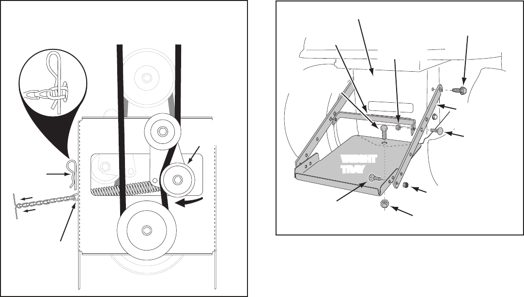
1. Cross Brace (Weight Tray)
2. Side Braces (2) (Weight Tray)
3. Left Hand Side Plate
4. Right Hand Side Plate
5. Anti-rotation Bracket
6. Engagement Rod (Not used on some models)
7. Suspension Arms (2)
8. Engine Pulley Keeper (Not used on some models)
9. Chute Crank Rod Assembly
10. Support Tube, Crank Rod
11. Lift Handle and Cable
12. Cable Bracket
13. Plastic Keg
14. L.H. Hanger Bracket (Outside Mounting)
15. R.H. Hanger Bracket (Outside Mounting)
16. Clutch Idler Assembly
17. V-Belt,Drive(Short)#46989
18 V-Belt,Drive(Long)#48138
19. V-Belt, Auger (Attached to Housing Assembly)
20. Chute and Control Cable Assembly
21. Housing Assembly
22. Weight Tray
23. L.H. Hanger Bracket (Inside Mounting)
24. R.H. Hanger Bracket (Inside Mounting)
Hardware Package (Stored inside Plastic Keg)
1
17
7
2356
8
15
11
10
12
22
24
23
14
20
19
18
21
13
16
9
4
CARTON CONTENTS

7
• Removeallpartsandhardwarepackagesfromthe
carton. Lay out parts and hardware and identify using
the illustrations on pages 4 and 6.
NOTE: Not all of the supplied parts and hardware will be
needed for your particular tractor. Unneeded items may
bediscardedafteryouhavecompletedassemblyand
checked operation of unit. DO NOT DISCARD the two
spare shear bolts (R) and 5/16" nylock nuts (CC). Refer
totheServiceandAdjustmentssectiononpage29.
REMOVAL OF PARTS FROM CARTON
TOOLS REQUIRED FOR ASSEMBLY
(2) 7/16" Wrenches
(2) 1/2" Wrenches
(2) 9/16" Wrenches
(2) 3/4" Wrenches
(1)ScrewDriver
(1) Knife
ADDITIONAL ITEMS REQUIRED
General Purpose Grease
TRACTOR PREPARATION
Beforeperformingtheseinstructions,refertotheService
andAdjustmentssectionofyourtractorowner'smanual
forspecicsafetyinstructions.
• Allowengine,muferandexhaustdeectortocool
before beginning.
• Removeanyfrontorrearattachmentwhichis
mounted to your tractor.
• Removethemowerdeck.Refertoyourtractorowner's
manualforremovalinstructions.Markalllooseparts
andsaveforreassembly.
• Removethetractorhood.Refertoyourtractorowner's
manualforremovalinstructions.
CAUTION: Before starting to assemble the
snowthrower,removethesparkplugwire(s),
setthe parkingbrakeand removethe key
from the tractor ignition.
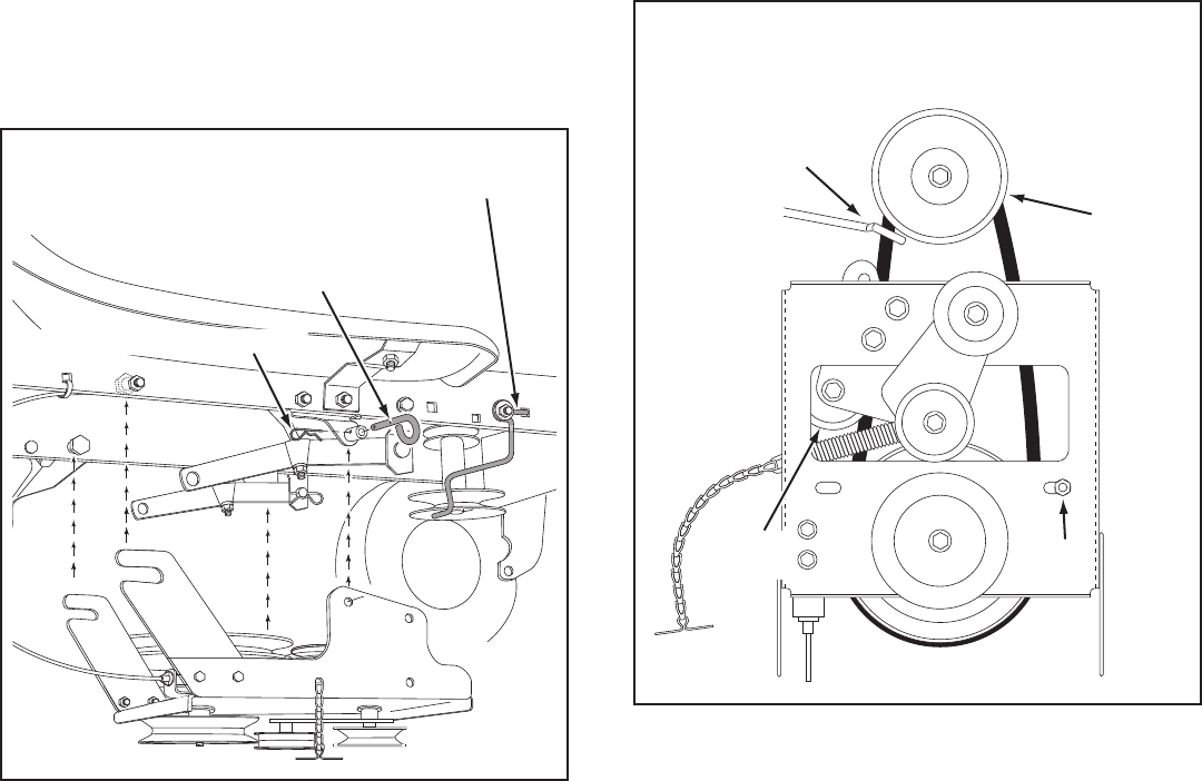
FIGURE 2 RIGHT SIDE VIEW
IMPORTANT: Right hand (R.H.) and left hand (L.H.) side
of the tractor are determined from the operators position
while seated on the tractor.
REMOVE
FRONT SCREWS
REMOVE
BROWNING SHIELD
MOWER DECK
SUSPENSION
BRACKET
FIGURE 1
INSTRUCTIONS FOR TRACTORS WITH
SINGLE FRONT DECK SUSPENSION
BRACKET
STEP 2: (SEE FIGURE 2)
• Removethebrowningshieldfromthefrontofthe
tractorasshown.Holdontotheshieldasyouremove
thesecondscrewtopreventitfromfalling.
• Besuretoreinstallthebrowningshieldwhenso
instructed in step 3.
IDENTIFY YOU TRACTOR
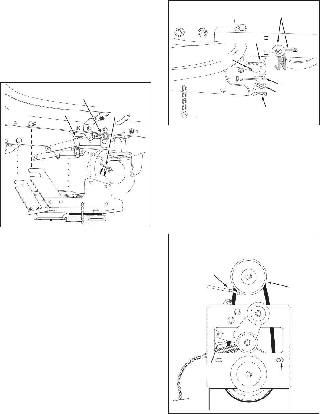
STEP 1: (SEE FIGURE 1)
• Lookunderthefrontofyourtractor.Ifthereisasingle
mower deck suspension bracket located underneath
the middle of the front axle, continue on to step
2. If your tractor does not have a mower deck
suspension bracket underneath the middle of the
front axle, skip to step 21 on page 13 for tractors
with dual suspension brackets.
ASSEMBLY
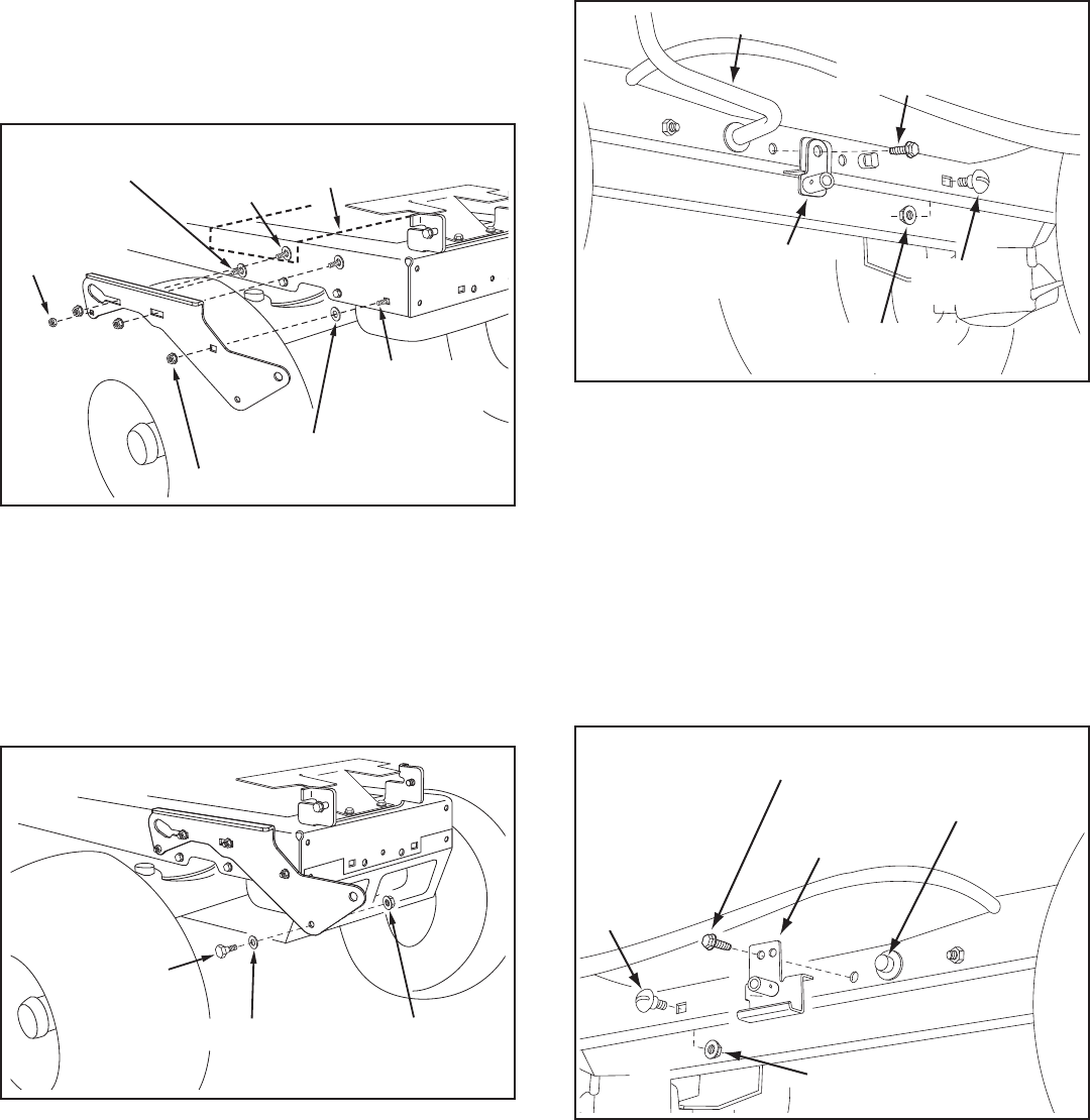
8
STEP 4: (SEE FIGURE 4)
• Assemble a shoulder bolt (P) and a 3/8" washer (X)
to the outside of R.H. side plate, securing it with a
3/8"angednut(BB).RepeatforL.H.sideplate.
FIGURE 4 RIGHT SIDE VIEW
FIGURE 3 RIGHT SIDE VIEW
5/16"
NYLOCK
NUT (CC)
5/16" x 1"
CARRIAGE BOLT (N) ENGINE MOUNTING
PLATE
(4) 1/2" WASHERS (V)
(3) 3/8" FLANGE NUTS (BB)
(3) 3/8" x 1"
CARRIAGE
BOLTS (K)
SEE NOTE
3/8" WASHER (X)
SHOULDER
BOLT (P)
3/8" FLANGED
NUT (BB)
INSTALL SIDE PLATES
STEP 3: (SEE FIGURE 3)
• FastentheR.H.SidePlate(bendfacingout)tothe
front three holes in the tractor frame using three
3/8" x 1" carriage bolts (K), three 1/2" washers (V)
(seenote)andthree3/8"angenuts(BB). For the
rear hole, use a 5/16" x 1" carriage bolt (N), a 1/2"
washer (V) and a 5/16" nylock nut (CC). Place the 1/2"
washers (V) between the tractor frame and the side
plate. Repeat for L.H. side plate.
• Reinstallthebrowningshieldontothetractorframe
using the original screws.
NOTE: If there is an engine mounting plate (shown with
dottedlines)leavethe1/2washerofftheboltthatgoes
through the plate.
INSTALL HANGER BRACKETS AND SHOULDER
BOLTS TO OUTSIDE OF FRAME
STEP 5: (SEE FIGURE 5)
• Removethebolt,ifpresent,intheholedirectlybehind
the brake rod on the left side of the tractor frame.
• AttachtheL.H.HangerBracket(tubefacingout)tothe
hole using a 5/16" x 3/4" self threading bolt (I).
• Installaroundheadshoulderbolt(Q)intothehole
that is 9-1/2" to the rear of the bolt you just installed.
Secureitwitha3/8"angenut(BB)ontheinsideof
the frame.
FIGURE 5 LEFT SIDE VIEW
5/16" x 3/4" SELF
THREADING BOLT (I)
L.H. HANGER
BRACKET
BRAKE ROD
3/8" FLANGED
NUT (BB)
SHOULDER
BOLT (Q)
5/16" x 3/4" SELF
THREADING BOLT (I)
R.H. HANGER
BRACKET
RIGHT END OF
BRAKE ROD
3/8" FLANGED
NUT (BB)
SHOULDER
BOLT (Q)
STEP 6: (SEE FIGURE 6)
• Removethebracket,ifpresent,fromtheholedirectly
behind the end of the brake rod on the right side of
the tractor frame. Store the bracket and bolt.
• AttachtheR.H.HangerBrackettotheholeusinga
5/16" x 3/4" self threading bolt (I).
• Installaroundheadshoulderbolt(Q)intothehole
that is 9-1/2" to the rear of the bolt you just installed.
Secureitwitha3/8"angenut(BB)ontheinsideof
the frame.
FIGURE 6 RIGHT SIDE VIEW
9
3/8" X 3-1/4"
HEX BOLT
(B)
LARGE SPACER (SS)
PULLEY (TT)
3/8" LOCKWASHER (S)
3/8" HEX LOCK NUT (DD) 3/8"
WASHER (X)
LONG END
OF HUB
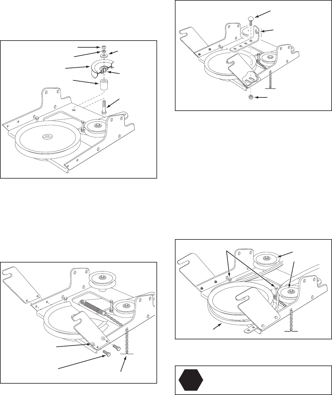
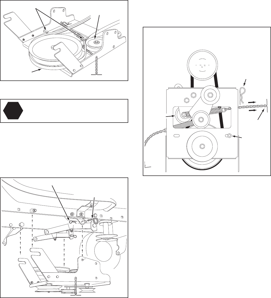
STEP 7: (SEE FIGURE 7)
• Attachthepulley(longendofhubfacingdown)and
the large spacer (SS) to the hole shown in the clutch/
idler assembly. Use a 3/8" x 3-1/4" hex bolt (B), a 3/8"
washer (X), a 3/8" lock washer (S) and a 3/8" hex lock
nut (DD).
FIGURE 7
FIGURE 9
STEP 9: (SEE FIGURE 9)
• Attachthecablebrackettotheslotshowninthe
clutch/idler assembly using a 5/16" x 3/4" carriage
bolt (O) and a 5/16" nylock nut (CC). Place the bolt in
the front hole of the bracket and in the end of the slot
closest to the pulley. Do not tighten yet.
CABLE
BRACKET
5/16" x 3/4"
CARRIAGE BOLT (O)
5/16" NYLOCK
NUT (CC)
THIS SECTION IS FOR TRACTORS WITH A
MANUAL ATTACHMENT CLUTCH
If your tractor has an electric attachment clutch go to
step 14 on page 11.
FIGURE 10
HEX BOLTS
(#48138)
DRIVE BELT
FLAT IDLER
PULLEYS
STOP
Didyouselectthecorrectdrivebeltforyour
tractor? Using the wrong length belt may
cause premature bearing or belt failure.
STEP 10: (SEE FIGURE 10)
• Twodifferentlengthdrivebeltsareincludedwith
your snow thrower. Tractors with manual attachment
clutches and single front deck suspension brackets use
the56"drivebeltwith#48138 printed on the outside of
the belt. DO NOT USE the other belt.
• Slightlyloosenthehexboltnexttotheatidlerpulley.
Installthedrivebeltdownbetweenthehexboltandthe
atidlerpulleywiththeatsideofthebeltagainstthe
pulley. Retighten the hex bolt.
• Loopthebeltaroundthelargev-pulley,placingit
betweenthev-pulleyandthehexboltnexttothepulley.
Placethebelttotheinsideoftheotheratidlerpulley.
5/16" NYLOCK
NUT (CC)
5/16" x 3/4"
HEX BOLT (E) TENSIONING CHAIN (PP)
FIGURE 8
STEP 8: (SEE FIGURE 8)
• Attachthetwosuspensionarmstotherearofthe
clutch/idler assembly using two 5/16" x 3/4" hex bolts
(E) and 5/16" nylock nuts (CC) for each arm. Place the
arms on the outside of the frame with the notches to
the rear.
• Insertatensioningchainthroughtheholeshownand
attach the end link to the spring on the lower idler arm.
10
ATTACH CLUTCH IDLER ASSEMBLY TO TRACTOR
STEP 12: (SEE FIGURE 12)
• Attachtheclutch/idlerassemblytothetractorframe.
Hook the notched suspension arms onto the two
shoulder bolts (Q) assembled to the outside of the
tractor frame. Lift the front of the assembly and attach
ittotheR.H.andL.H.hangerbracketsusingtwopivot
lock pins (MM) and 1/8" hairpin cotters (KK).
• Looselyattachthemowerclutchcabletotheleftside
of the tractor frame with a nylon tie (OO). Do not pull
the nylon tie completely tight. The cable may need to
beremovedfromthenylontiewhenusingthemower
deck.
PIVOT LOCK PIN (MM)
(use this hole)
SHOULDER
BOLT (Q)
L.H. HANGER
BRACKET
1/8" HAIRPIN
COTTER (KK)
NYLON TIE (OO)
MOWER
CLUTCH
CABLE
FIGURE 12 VIEWED FROM LEFT SIDE
STEP 13: (SEE FIGURE 13)
• Assemblethedrivebeltontotheenginepulleyrst
and then onto the large pulley on top of the clutch/
idler assembly. The belt must be placed inside the
engine pulley belt keeper(s) and between the large
pulley and the keeper bolt next to it.
IMPORTANT: Do Not assemble the "V" belt outside of
the engine pulley keepers or outside of the keeper bolt
next to the large pulley.
• Go to step 48 on page 21.
FIGURE 13 VIEWED FROM UNDERNEATH
ENGINE
PULLEY
ENGINE
PULLEY
Left Side
of Tractor
ENGINE
PULLEY
KEEPER
ENGINE
PULLEY
KEEPER
KEEPER BOLT
IDLER
PULLEY
FIGURE 11
5/64" HAIR
COTTER PIN
SPACER
1/4" WASHER
TRACTOR'S
CLUTCH CABLE
CABLE
BRACKET GROOVE
5/64" HAIR
COTTER PIN (JJ)
1/4" WASHER (T)
SPACER (RR)
TRACTOR'S
CLUTCH CABLE
CABLE
BRACKET
5/64" HAIR
COTTER PIN (JJ)
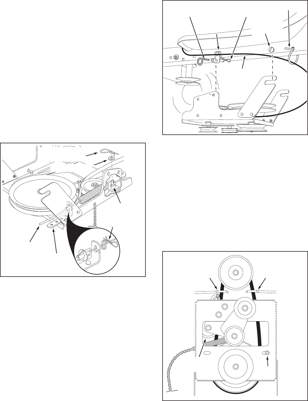
STEP 11: (SEE FIGURE 11)
• Findthecableclipthatisattachedtotheleftside
of the tractor frame underneath the footrest. Open
theclipandremovethemowerclutchcable.Do not
remove the clip from the tractor frame. The cable
reattaches to the clip when using the mower deck.
• Movetheattachmentclutchleveronthedashpanelto
the disengaged position.
• Placetheclutch/idlerassemblyontheoorontheleft
side of the tractor.
• Attachthetractor'smowerclutchcabletothecable
bracket on the clutch/idler assembly. Secure the cable
housingguide(groovedown)tothecablebracket
using the original collar and a 5/64" hair cotter pin ( JJ).
• Placeaspacer(RR)ontheweldedpinontheidler
arm.Hooktheendoftheclutchcablespringoverthe
pin and secure it with a 1/4" washer (T) and a 5/64"
hair cotter pin (JJ).
• Aligncablebracketwithweldedpinandtightenthe
nut assembled in step 9.
11
THIS SECTION IS FOR TRACTORS WITH AN
ELECTRIC ATTACHMENT CLUTCH
STEP 14: (SEE FIGURE 14)
• Attachthetwosuspensionarmstotherearofthe
clutch/idler assembly using two 5/16" x 3/4" hex bolts
(E) and 5/16" nylock nuts (CC) for each arm. Place the
arms on the outside of the frame with the notches to
the rear.
• Insertatensioningchainthroughtheholeshownand
attach the end link to the spring on the lower idler arm.
FIGURE 14 FIGURE 16 VIEW OF BOTTOM
STEP 16: (SEE FIGURE 16)
• Hookoneendofthespringsuppliedinthepartsbag
through the end link of the tensioning chain.
• Withtheclutch/idlerassemblyturnedupsidedown,
hook the other end of the spring onto the end of the
bolt and nut which secure the idler pulley to the upper
idler arm. Assemble a 3/8" hex lock nut (DD) onto the
boltandnut,leavingenoughgapbetweenthenutsfor
thespringtopivotfreely.
• Attacha3/32"hairpincotter(LL)tothechain,placing
itinthefthlinkfromthespring.
CHAIN
(L.H. SIDE)
3/32" HAIR
COTTER PIN (LL)
5TH LINK
LEFT
SIDE
3/8" HEX
LOCK NUT (DD)
SPRING
RIGHT
SIDE
ATTACH
SPRING
HERE
STEP 15: (SEE FIGURE 15)
• Turntheclutch/idlerassemblyupsidedownandplace
the extra tensioning chain (PP) through the left front
hole.
FIGURE 15
TENSIONING CHAIN (PP)
LEFT FRONT HOLE
STEP 17: (SEE TABLE 1)
• Twodifferentlengthdrivebeltsareincludedwith
your snow thrower. Use the table below to select
thecorrectdrivebeltforyourtypetractor.Thepart
number is printed on the outside of the belt .
• Setasidethebeltthatisnotforyourtractortoavoid
accidentally using it.
SELECT THE CORRECT DRIVE BELT
(Electric clutch tractors with a single front deck
suspension bracket)
55" BELT (PART #46989)
TRACTOR TYPE DECK SIZE CLUTCH TYPE
(LT) Lawn Tractor 38", 42" Electric
56" BELT (PART #48138)
TRACTOR TYPE DECK SIZE CLUTCH TYPE
(LT) Lawn Tractor 48" Electric
(GT) Garden Tractor 48", 54" Electric
TABLE 1
5/16" NYLOCK
NUT (CC)
5/16" x 3/4"
HEX BOLT (E) TENSIONING CHAIN (PP)
12
STEP 19: (SEE FIGURE 18)
• Attachtheclutch/idlerassemblytothetractorframe.
Hook the notched suspension arms onto the two
shoulder bolts (Q) assembled to the outside of the
tractor frame. Lift the front of the assembly and attach
ittotheR.H.andL.H.hangerbracketsusingtwopivot
lock pins (MM) and 1/8" hairpin cotters (KK).
PIVOT LOCK PIN (MM)
(use second hole) SHOULDER
BOLT (Q)
1/8" HAIRPIN
COTTER (KK)
L.H. HANGER
BRACKET
FIGURE 18 VIEWED FROM LEFT SIDE
STEP 20: (SEE FIGURE 19)
• Assemblethedrivebeltontotheenginepulleyrst
and then onto the large pulley on top of the clutch/
idler assembly. Place the belt to the inside of the idler
pulley and the belt keeper bolt located beside the
large pulley.
• Placetensiononthebeltbypullingtheleftside
tensioning chain (PP) out as far as the 3/32" hairpin
cotter in the chain will allow. Secure the chain in this
position by inserting a 1/8" hairpin cotter (KK) through
the chain.
IMPORTANT: Do Notassemblethedrivebeltaroundthe
outside of the keeper bolt beside the large pulley.
• Go to step 48 on page 21.
FIGURE 19 VIEWED FROM UNDERNEATH
1/8" HAIRPIN
COTTER (KK)
ENGINE
PULLEY
ENGINE
PULLEY
KEEPER
BOLT
IDLER
PULLEY
CHAIN (PP)
(L.H. SIDE)
FIGURE 17
STEP 18: (SEE FIGURE 17)
• Turntheclutch/idlerassemblyrightsideup.
• Slightlyloosenthehexboltnexttotheatidlerpulley.
Installthedrivebeltdownbetweenthehexboltandthe
atidlerpulleywiththeatsideofthebeltagainstthe
pulley. Retighten the hex bolt.
• Loopthebeltaroundthelargev-pulley,placingit
betweenthev-pulleyandthehexboltnexttothepulley.
STOP
Didyouchoosethecorrectdrivebeltfor
your tractor? Using the wrong length belt
may cause premature bearing or belt failure.
CLUTCH/IDLER ASSEMBLY
HEX BOLTS
DRIVE BELT
FLAT IDLER
PULLEY
13
STEP 22: (SEE FIGURE 21)
• FastentheR.H.SidePlate(bendfacingout)tothe
front three holes shown in the tractor frame using
three 3/8" x 1" thread forming bolts (G), three 3/8"
lock washers (S) and one 1/2" washer (V) placed on
the third bolt as a shim between the side plate and
the frame. Tighten all bolts. Repeat for the L.H. side.
NOTE: If you installed a bolt in the fourth hole in step 21,
assemblea5/16"angenut(AA)ontotheboltafterthe
side plate is installed.
• Go to step 25 on this page.
(3) 3/8" x 1"
THREAD FORMING
BOLTS (G)
5/16" FLANGED
NUT (AA)
(SEE NOTE) (3) 3/8" LOCK
WASHERS (S)
1/2" WASHER (V)
5/16" x 1"
CARRIAGE BOLT (N)
(SEE NOTE)
FIGURE 21 RIGHT SIDE VIEW
SUSPENSION
BRACKET
REMOVE BOLTS
IF PRESENT
FIGURE 22 RIGHT SIDE VIEW
STEP 23: (SEE FIGURE 22)
• Removeanyboltsfoundintheholesshown.
STEP 24: (SEE FIGURE 23)
• Fasten the R.H. Side Plate (bend facing out) to the
three holes shown in the tractor frame. Use three 3/8" x
1" thread forming bolts (G), 1/2" washers (V) and 3/8"
lock washers (S). Tighten all bolts and repeat for the
L.H. side.
NOTE: If the bolt inserts freely into the front hole, assemble
a3/8"angednut(BB)ontothebolt.
(3) 3/8" x 1"
THREAD FORMING
BOLTS (G)
(3) 3/8" LOCK
WASHERS (S)
3/8" FLANGED NUT (BB)
(SEE NOTE)
(3) 1/2" WASHERS (V)
FIGURE 23 RIGHT SIDE VIEW
STEP 21: (SEE FIGURE 20)
• Removeboltsfromfrontthreeholesshown.
• Ifaboltispresentinthefourthhole,replaceitwitha
5/16" x 1" carriage bolt (N) without a nut. The bracket
fastened to inside of frame must remain in place.
FRONT
SUSPENSION
BRACKET
REPLACE BOLT
(IF PRESENT)
REMOVE BOLTS
(IF PRESENT)
FIGURE 20 RIGHT SIDE VIEW
INSTRUCTIONS FOR TRACTORS WITH DUAL
FRONT DECK SUSPENSION BRACKETS
FASTEN SIDE PLATES TO TRACTOR
Ifyourtractorresemblesgure20,gotostep21.
Ifyourtractorresemblesgure22,gotostep23.
STEP 25: (SEE FIGURE 24)
• Assemble a shoulder bolt (P) and a 3/8" washer (X)
to the outside of each side plate, securing them with
a3/8"angednut(BB).
FIGURE 24 RIGHT SIDE VIEW
3/8" WASHER (X)
SHOULDER
BOLT (P)
3/8" FLANGED
NUT (BB)
14
FIGURE 28 RIGHT SIDE VIEW
INSTALLING HANGER BRACKETS
Forbetterclearance,lowerthetractor'ssuspensionarms
usingtheattachmentliftlever.
STEP 26: (SEE FIGURE 25 or 26)
On Tractors With Foot Rest Brackets
• RemovetheboltandnutthatfastentheL.H.andR.H.
foot rest brackets to the frame.
• AttachtheL.H.HangerBracket(marked"L")tothe
inside of the tractor frame using two 3/8" x 1" carriage
bolts(K)and3/8"angednuts(BB).Boltheadsgoon
inside of tractor frame. Repeat for the R.H. side.
FIGURE 26 LEFT SIDE VIEW
FIGURE 25 LEFT SIDE VIEW
On Tractors Without Foot Rest Brackets
• Findtheemptyholebeneaththefootrest.Attachthe
L.H. Hanger Bracket (marked "L") to the inside of the
frame using a 3/8" x 1" carriage bolt (K) and a 3/8"
angednut(BB).Boltheadgoesoninsideoftractor
frame. Repeat for the R.H. side.
STEP 28: (SEE FIGURE 28)
• Assembleashoulderbolt(P)and3/8"angednut
(BB) to the R.H. side of the tractor frame, using the
rstemptyholetotherearoftheR.H.hangerbracket.
Bolt goes on inside of frame.
FIGURE 27 LEFT SIDE VIEW
INSTALLING SHOULDER BOLTS
STEP 27: (SEE FIGURE 27)
• Removethebolt,washerandnutwhichfastenthe
sway bar bracket to the L.H. side of the tractor frame.
Replacewithashoulderbolt(P)anda3/8"anged
nut (BB). Bolt goes on inside of frame.
BOLT REMOVED
FROM THIS HOLE
SWAY BAR
BRACKET
SHOULDER BOLT (P)
3/8"
FLANGED
NUT (BB)
3/8" x 1"
CARRIAGE
BOLT (K)
3/8" FLANGED
NUT (BB)
L.H. HANGER
BRACKET
SUSPENSION ARM
SHOULDER BOLT (P)
3/8"
FLANGED
NUT (BB)
R.H. HANGER BRACKET
BOLT REMOVED
FROM THIS HOLE
3/8" x 1"
CARRIAGE
BOLT (K)
3/8" FLANGED
NUT (BB)
L.H. HANGER
BRACKET
SUSPENSION ARM
15
INSTALLING CLUTCH/IDLER ASSEMBLY
ThissectioncoverstheinstallationoftheClutch/Idler
assembly to tractors with attachment clutches that are
either rod operated (p. 15), cable operated (p. 17) or
electric (p. 19). Use the appropriate instructions for your
tractor.
ROD OPERATED MANUAL ATTACHMENT CLUTCH
STEP 29: (SEE FIGURE 29)
• Movetheattachmentclutchleveronthedashpanelto
the disengaged (down) position.
• Screwthetrunnion(II)ontotheendofthesnow
thrower engagement rod.
• Locatetheclutcharm(wherethemowerclutchrod
was connected) underneath the right hand side the
tractor, just to the inside of the suspension arm. If
there is an extensionattachedtotheclutchlever,the
extension,boltandnutmustberemovedandstored
with the mower deck.
IMPORTANT: Re-attach the extension to the clutch
leverbeforereinstallingthemowerdeck.
• Positiontheengagementrodtotheinsideofthe
clutch arm and insert the drilled end of the rod
through the arm. Secure with a 5/64" hairpin cotter
(JJ).
FIGURE 29 RIGHT SIDE VIEW
ENGAGEMENT ROD
5/64" HAIRPIN
COTTER (JJ)
TRACTOR'S CLUTCH ARM
SUSPENSION ARM
TRUNNION (II)
REMOVE EXTENSION,
BOLT AND NUT
(IF PRESENT)
STEP 30: (SEE FIGURE 30)
• Attachthetwosuspensionarmstotheinsideofthe
clutch/idler assembly using two 5/16" x 3/4" hex bolts
(E), 5/16" washers (U) and 5/16" nylock nuts (CC) for
each arm. Place the washers between the arms and
the assembly frame.
• Insertatensioningchainthroughtheholeshownand
attach the end link to the spring on the lower idler arm.
FIGURE 30
5/16" x 3/4"
HEX BOLT (E)
5/16" NYLOCK
NUT (CC)
TENSIONING CHAIN (PP)
5/16" WASHER (U)
FIGURE 31
STOP
Didyouchoosethecorrectdrivebeltfor
your tractor? Using the wrong length belt
may cause premature bearing or belt failure.
HEX BOLTS
DRIVE BELT
FLAT IDLER
PULLEY
(#46989)
STEP 31: (SEE FIGURE 31)
• Twodifferentlengthdrivebeltsareincludedwith
your snow thrower. Tractors with manual attachment
clutches and dual front deck suspension brackets use
the55"drivebeltwith#46989 printed on the outside
of the belt. DO NOT USE the other belt.
• Slightlyloosenthehexboltnexttotheatidlerpulley.
Installthedrivebeltdownbetweenthehexboltandthe
atidlerpulleywiththeatsideofthebeltagainstthe
pulley. Retighten the hex bolt.
• Loopthebeltaroundthelargev-pulley,placingit
betweenthev-pulleyandthehexboltnexttothepulley.
16
FIGURE 33 RIGHT SIDE VIEW
FIGURE 32 RIGHT SIDE VIEW
PIVOT LOCK PIN (MM)
(use second hole)
1/8" HAIRPIN COTTER (KK)
ENGAGEMENT
ROD
STEP 33: (SEE FIGURE 33)
• Makesuretheattachmentclutchleveronthedash
panel is in the disengaged (down) position.
• Pivottheupperidlerarmsothatitrestsagainstthe
stop bolt and is pointing toward the front as shown.
Screw the trunnion (II) along the threads of the
engagement rod until it is aligned at the front end of
the idler arm slot. Attach the trunnion (II) to the slot
using the 3/8" thin washer (W) and a 5/64" hairpin
cotter (JJ).
• Removetheenginepulleykeeperfromthesideof
thetractorframebyremovingthewasherandnut
that secure the keeper. Attach the new pulley keeper
supplied with the snow thrower, reusing the original
bolt, washer and nut.
NOTE: Some tractors may already be equipped with a
pulley keeper that is identical to the new one supplied.
IDLER ARM
5/64" HAIRPIN
COTTER (JJ)
TRUNNION (II)
STOP BOLT
3/8" THIN
WASHER (W)
NEW ENGINE PULLEY KEEPER WITH
ORIGINAL BOLT, NUT AND WASHER
STEP 34: (SEE FIGURE 34)
• Assembletheshort"V"beltontotheenginepulley
and then onto the large pulley on top of the clutch/idler
assembly. The belt must be placed to the inside of the
engine pulley keeper, the idler pulley and the keeper
bolt located beside the large pulley.
IMPORTANT: Do Not assemble the "V" belt around the
outside of the engine pulley keeper or the keeper bolt.
• Go to step 48 on page 21.
FIGURE 34 VIEWED FROM UNDERNEATH
ENGINE
PULLEY
KEEPER BOLT
IDLER
PULLEY
ENGINE
PULLEY
KEEPER
Left Side
of Tractor
CLUTCH/IDLER ASSEMBLY
STEP 32: (SEE FIGURE 32)
• Besuretoliftupthefrontendoftheengagementrod
as shown when performing the next operation. You
can temporarily support the rod using a rubber band
tied to the engine pulley keeper.
• Attachtheclutch/idlerassemblytothetractorframe
asfollows.Hooktheassembly'snotchedarmsonto
the two shoulder bolts you assembled to the inside
of the tractor frame. Lift the front of the assembly and
attach it to the R.H. and L.H. hanger brackets using
twopivotlockpins(MM)and1/8"hairpincotters(KK).
17
FIGURE 36
FIGURE 38
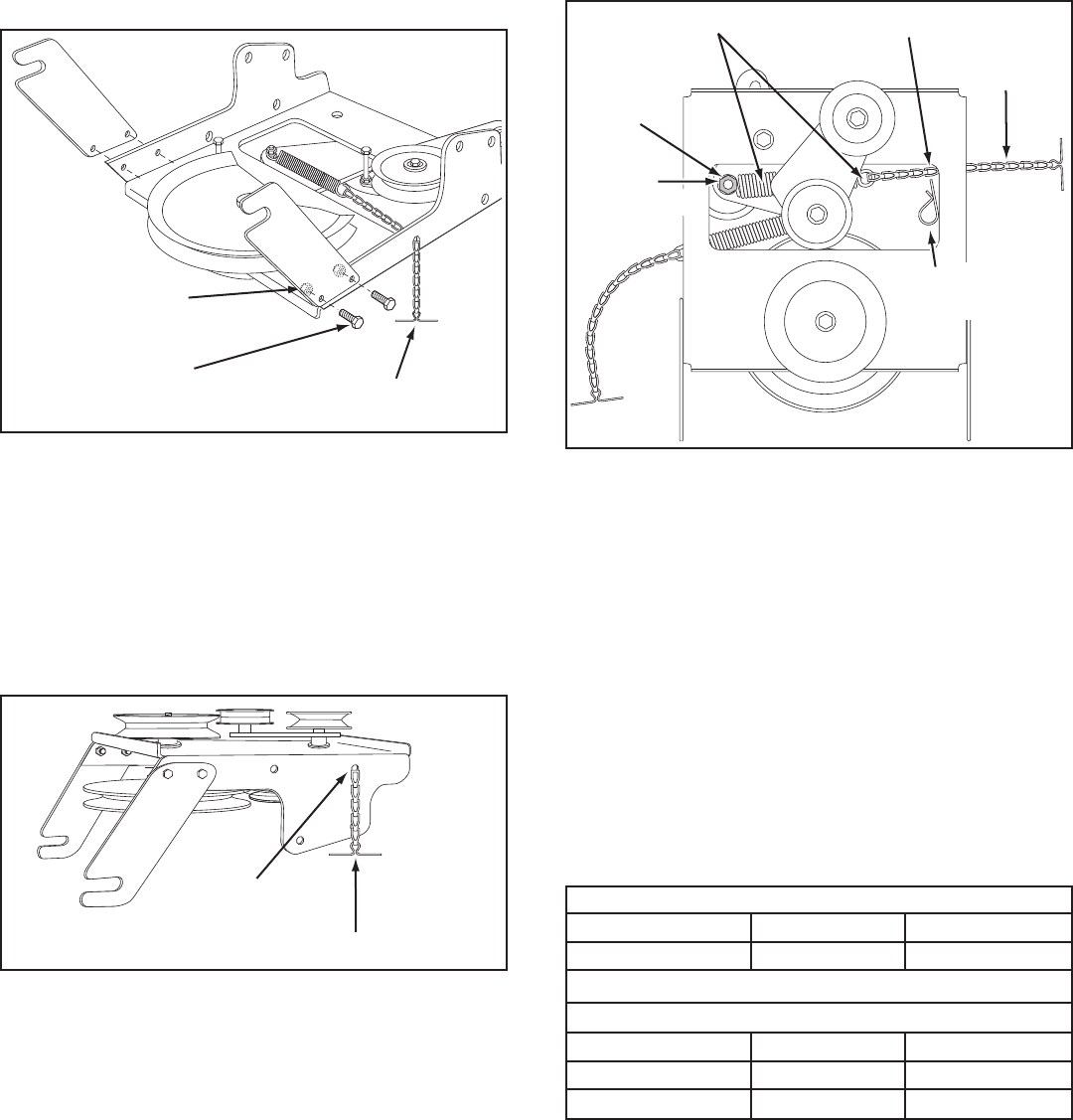
STEP 36: (SEE FIGURE 36)
• Assemblethecablebrackettotheinnerhalfofthe
double holes in the bottom of the clutch/idler assembly
using two 5/16" x 3/4" carriage bolts (O) and 5/16"
nylock nuts (CC). Use the front holes in the cable
bracket if your tractor has a 42" mower deck. Use the
rear holes if your tractor has a 46" mower deck.
STEP 38: (SEE FIGURE 38)
• Movetheattachmentclutchleveronthedashpanelto
the disengaged (down) position.
• Placetheclutch/idlerassemblyontheoorontheright
side of the tractor.
• Attachthetractor'sclutchcabletothecablebracket.
Securethecablehousingguide(groovedown)tothe
cable bracket using the original collar and a 5/64" hair
cotter pin (JJ ).
• Placeaspacer(RR)ontheweldedpinontheidler
arm.Hooktheendoftheclutchspringoverthepinand
secure it with a 1/4" washer (T) and a 5/64" hair cotter
pin (JJ).
CABLE
BRACKET
5/16" x 3/4"
CARRIAGE BOLT (O)
5/16" NYLOCK
NUT (CC)
42"
DECKS
46"
DECKS
GROOVE
TRACTOR'S
CLUTCH CABLE
5/64" HAIR
COTTER PIN (NN)
1/4" WASHER (X)
SPACER (HH)
TRACTOR'S
CLUTCH CABLE
5/64" HAIR
COTTER PIN (JJ)
1/4" WASHER (T)
SPACER (RR)
5/64" HAIR
COTTER PIN (JJ)
STEP 35: (SEE FIGURE 35)
• Attachthetwosuspensionarmstotheinsideofthe
clutch/idler assembly using two 5/16" x 3/4" hex bolts
(E), 5/16" washers (U) and 5/16" nylock nuts (CC) for
each arm. Place the washers between the arms and
the assembly frame.
• Insertatensioningchainthroughtheholeshownand
attach the end link to the spring on the lower idler arm.
FIGURE 35
5/16" x 3/4"
HEX BOLT (E)
5/16" NYLOCK
NUT (CC)
TENSIONING CHAIN (PP)
5/16" WASHER (U)
CABLE OPERATED MANUAL ATTACHMENT CLUTCH
FIGURE 37
HEX BOLTS
DRIVE BELT
FLAT IDLER
PULLEY
(#46989)
STEP 37: (SEE FIGURE 37)
• Twodifferentlengthdrivebeltsareincludedwith
your snow thrower. Tractors with manual attachment
clutches and dual front deck suspension brackets use
the55"drivebeltwith#46989 printed on the outside
of the belt. DO NOT USE the other belt.
STOP
Didyouchoosethecorrectdrivebeltfor
your tractor? Using the wrong length belt
may cause premature bearing or belt failure.
• Slightlyloosenthehexboltnexttotheatidlerpulley.
Installthedrivebeltdownbetweenthehexboltandthe
atidlerpulleywiththeatsideofthebeltagainstthe
pulley. Retighten the hex bolt.
• Loopthebeltaroundthelargev-pulley,placingit
betweenthev-pulleyandthehexboltnexttothepulley.
18
FIGURE 40 VIEWED FROM UNDERNEATH
FIGURE 39
STEP 40: (SEE FIGURE 40)
• Assembletheshort"V"beltontotheenginepulley
and then onto the large pulley on top of the clutch/idler
assembly. The belt must be placed to the inside of the
engine pulley keeper, the idler pulley and the keeper
bolt located beside the large pulley.
IMPORTANT: Do Not assemble the "V" belt around the
outside of the engine pulley keeper or the keeper bolt.
• Go to step 48 on page 21.
STEP 39: (SEE FIGURE 39)
• Removetheenginepulleykeeperfromthesideof
thetractorframebyremovingthewasherandnut
that secure the keeper. Attach the new pulley keeper
supplied with the snow thrower, reusing the original
bolt, washer and nut.
NOTE: Some tractors may already be equipped with a
pulley keeper that is identical to the new one supplied.
• Attachtheclutch/idlerassemblytothetractorframe
asfollows.Hooktheassembly'snotchedarmsonto
the two shoulder bolts you assembled to the inside
of the tractor frame. Lift the front of the assembly and
attach it to the R.H. and L.H. hanger brackets using
twopivotlockpins(MM)and1/8"hairpincotters(KK).
NEW ENGINE PULLEY KEEPER WITH
ORIGINAL BOLT, NUT AND WASHER
PIVOT LOCK PIN (MM)
(use second hole)
1/8" HAIRPIN COTTER (KK)
ENGINE
PULLEY
KEEPER BOLT
IDLER
PULLEY
ENGINE
PULLEY
KEEPER
Left Side
of Tractor
CLUTCH/IDLER ASSEMBLY
19
ELECTRIC ATTACHMENT CLUTCHES
FIGURE 42
TENSIONING CHAIN (PP)
LEFT FRONT HOLE
FIGURE 43 VIEW OF BOTTOM
STEP 43: (SEE FIGURE 43)
• Hookthespringfromthepartsbagthroughtheendof
the tensioning chain.
• Hooktheotherendofthespringontothebottomof
the bolt and nut which secure the idler pulley to the
upper idler arm. Hold the bolt head and assemble a
3/8"hexlocknut(DD)ontothebolt,leavingenough
spaceforthespringtopivotfreelybetweenthetwo
nuts.
• Attacha3/32"hairpincotter(LL)tothechain,placing
itinthefthlinkfromthespring.
CHAIN
(L.H. SIDE)
3/32" HAIR
COTTER PIN (LL)
5TH LINK
LEFT
SIDE
3/8" HEX
LOCK NUT (DD)
SPRING
RIGHT
SIDE
ATTACH
SPRING
HERE
STEP 44: (SEE TABLE 2)
• Twodifferentlengthdrivebeltsareincludedwith
your snow thrower. Use the table below to select
thecorrectdrivebeltforyourtypetractor.Thepart
number is printed on the outside of the belt .
• Setasidethebeltthatisnotforyourtractortoavoid
accidentally using it.
55" BELT (PART #46989)
TRACTOR TYPE DECK SIZE CLUTCH TYPE
56" BELT (PART #48138)
TRACTOR TYPE DECK SIZE CLUTCH TYPE
(LT) Lawn Tractor 48" Electric
(LT) Lawn Tractor 38", 42", 46" Electric
TABLE 2
STEP 41: (SEE FIGURE 41)
• Attachthetwosuspensionarmstotheinsideofthe
clutch/idler assembly using two 5/16" x 3/4" hex bolts
(E), 5/16" washers (U) and 5/16" nylock nuts (CC) for
each arm. Place the washers between the arms and
the assembly frame.
• Insertatensioningchainthroughtheholeshownand
attach the end link to the spring on the lower idler arm.
FIGURE 41
STEP 42: (SEE FIGURE 42)
• Pacetheextratensioningchain(PP)throughtheleft
front hole in the clutch/idler assembly and then turn
the assembly upside down.
5/16" x 3/4"
HEX BOLT (E)
5/16" NYLOCK
NUT (CC)
TENSIONING CHAIN (PP)
5/16" WASHER (U)
20
FIGURE 46 VIEWED FROM UNDERNEATH
1/8" HAIRPIN
COTTER (KK)
ENGINE
PULLEY
ENGINE
PULLEY
KEEPER
BOLT
IDLER
PULLEY
CHAIN (PP)
(L.H. SIDE)
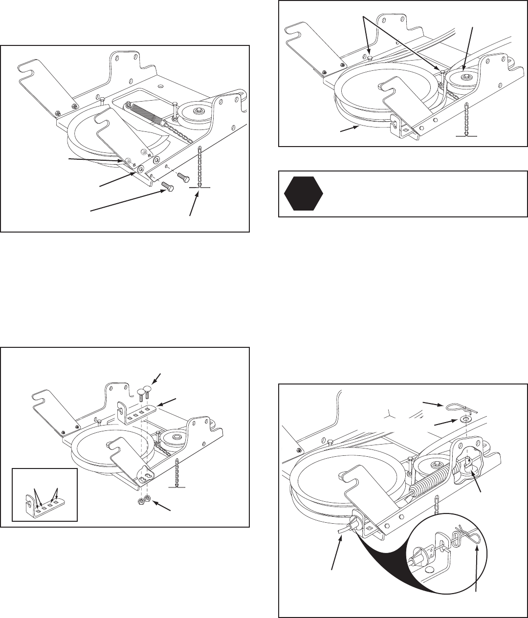
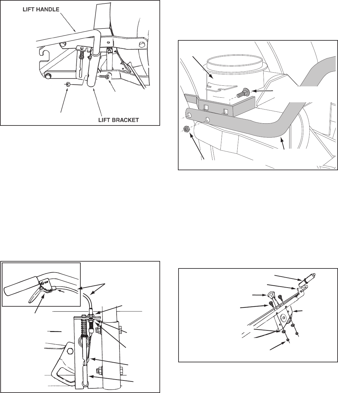
STEP 47: (SEE FIGURE 46)
• Assemblethedrivebeltontotheenginepulleyand
then onto the large pulley on top of the clutch/idler
assembly. The belt must be placed to the inside of
the idler pulley and the keeper bolt located beside the
large pulley.
• Placetensiononthebeltbypullingtheleftside
tensioning chain out as far as the 3/32" hairpin cotter
(LL) will allow. Secure the chain in this position by
inserting a 1/8" hairpin cotter (KK) through the chain.
IMPORTANT: Do Not assemble the "V" belt around the
outside of the engine pulley keeper or the keeper bolt.
STEP 46: (SEE FIGURE 45)
• Attachtheclutch/idlerassemblytothetractorframe
asfollows.Hooktheassembly'snotchedarmsonto
the two shoulder bolts you assembled to the inside
of the tractor frame. Lift the front of the assembly and
attach it to the R.H. and L.H. hanger brackets using
twopivotlockpins(MM)and1/8"hairpincotters(KK).
FIGURE 45 RIGHT SIDE VIEW
PIVOT LOCK PIN (MM)
(use second hole)
1/8" HAIRPIN COTTER (KK)
CLUTCH/IDLER ASSEMBLY
HEX BOLTS
DRIVE BELT
FLAT IDLER
PULLEY
FIGURE 44
STOP
Didyouchoosethecorrectdrivebeltfor
your tractor? Using the wrong length belt
may cause premature bearing or belt failure.
STEP 45: (SEE FIGURE 44)
• Turntheclutch/idlerassemblyrightsideup.
• Slightlyloosenthehexboltnexttotheatidlerpulley.
Installthedrivebeltdownbetweenthehexboltandthe
atidlerpulleywiththeatsideofthebeltagainstthe
pulley. Retighten the hex bolt.
• Loopthebeltaroundthelargev-pulley,placingit
betweenthev-pulleyandthehexboltnexttothepulley.
Placethebelttotheinsideoftheotheratidlerpulley.
21
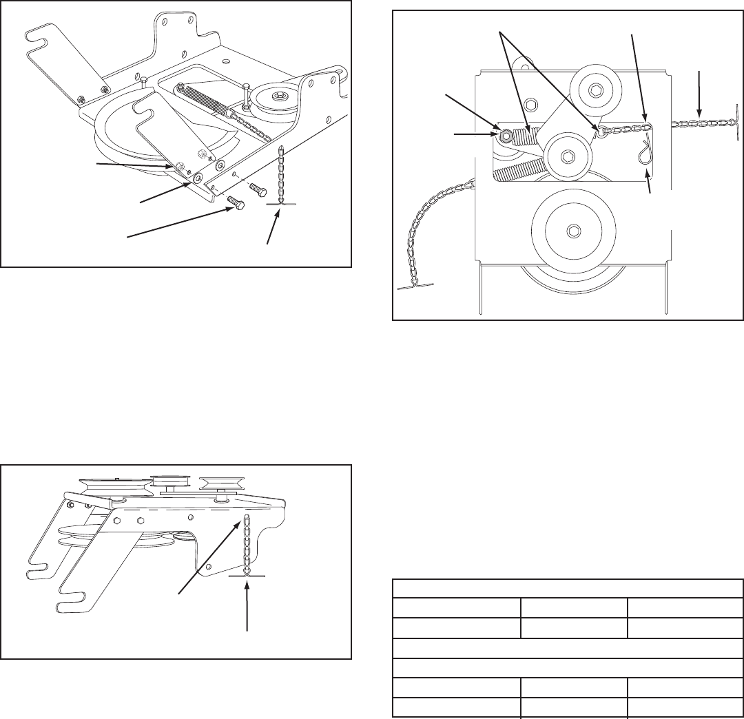
STEP 48: (SEE FIGURE 47)
• Placethelifthandleintotheliftbracketontherightside
of the snow thrower. Fasten the handle to the bracket
using two 5/16" x 1-3/4" hex bolts (D) and 5/16" Nylock
nuts (CC).
FIGURE 48 RIGHT SIDE VIEW
LIFT RELEASE
CABLE
HEX NUT
LOCK
WASHER
HEX NUT
CABLE
WIRE
LIFT
ROD
TRIGGER
ASSEMBLY
NOTE:Besuretheliftreleasecable'splasticcovering
stays inserted into the trigger assembly for the next step.
STEP 49: (SEE FIGURE 48)
• Pushthelifthandledownintothelockedposition.
Insert the end of the cable wire into the hole in the
liftrod.Placethethreadedttingintotheslotinthe
liftbracket,withonehexnutaboveandonehexnut
and the lock washer below the slot. Tighten the nuts,
adjusting them to eliminate slack in the cable wire.
ReferalsototheServiceandAdjustmentssectionon
page 29 in this manual.
HINT: For easier assembly of the lift release cable, tilt the
snow thrower forward onto the spiral auger.
FIGURE 47 RIGHT SIDE VIEW
5/16" NYLOCK NUT (CC)
5/16" x 1-3/4"
HEX BOLT (D)
ASSEMBLY OF THE SNOW THROWER STEP 50: (SEE FIGURE 49)
• Tiltthesnowthrowerbackdowntotheground.
• Removethenylontiewhichfastenstheauger
drivebelttothedischargehousing,leavingthebelt
assembled around the pulleys.
• Removethenylontiewhichfastensthechutecrank
rod to the crank rod support tube.
• Assemblethecrankrodsupporttubetothebracket
on the left side of the discharge housing using two
5/16" x 1-1/4" carriage bolts (M), and 5/16" Nylock
nuts (CC).
FIGURE 50 LEFT SIDE VIEW
CHUTE CRANK ROD
CRANK SUPPORT TUBE
TILT CONTROL HANDLE
5/16" x 1-3/4"
CARRIAGE BOLT (L)
BOWED WASHER (Y)
5/16" NYLOCK NUT (CC)
TILT
CONTROL
ASSEMBLY
STEP 51: (SEE FIGURE 50)
• Attachthechutetiltcontrolassemblytothetopside
of the crank support tube using two 5/16" x 1-3/4"
carriage bolts (L), bowed washers (Y) and 5/16"
Nylock nuts (CC).
5/16" NYLOCK NUT (CC)
5/16" x 1-1/4"
CARRIAGE BOLT (M)
CRANK ROD
SUPPORT TUBE
DISCHARGE
HOUSING
FIGURE 49 LEFT SIDE VIEW
22
5/16" NYLOCK NUT (CC)
CHUTE CRANK
BRACKET
5/16" WASHER (U)
CHUTE
CRANK
ROD
ROD
SUPPORT
BRACKET
5/16" x 1"
CARRIAGE BOLT (N)
SPIRAL
FIGURE 51 LEFT SIDE VIEW
FIGURE 52 RIGHT SIDE VIEW
CHUTE KEEPER (HH)
ANTI-ROTATION
BRACKET
1/4" FLANGED
LOCK NUT (Z)
1/4" FLAT
WASHER (T)
1/4" x 1"
HEX BOLT (F)
PLASTIC CAP (NN)
GREASED
SURFACE
FLANGE
STEP 53: (SEE FIGURE 52)
• Coatthetopoftheringaroundthedischargeopening
with general purpose grease.
• Placethedischargechute(facingforward)ontothe
ring. Place the anti-rotation bracket on top of the chute
ange,aligningitwiththeholesontherighthandside
oftheange.Attachthethreechutekeepers(HH)
(rightsideupasshown)tothebottomoftheange
usingsix1/4"x1"hexbolts(F),1/4"atwashers(T)
and1/4"angedlocknuts(Z).Tighten carefully so
that the nuts are snug but do not dig into the plastic
chute keepers.
• Placetheplasticcap(NN)ontotheshortendofthe
anti-rotation bracket.
• Positionthecrankrodspiral(seegure51)sothatit
does not rub against the bottoms of the notches in the
chuteange.Tighten the nuts.
• Checkifthecrankrodrotatesthechutefreely.Ifnot,
loosen by 1/4 turn each of the six hex bolts holding
thechutekeeperstothechuteange.
• Securethecontrolcablestothecrankrodsupport
tube using a nylon tie (OO).
STEP 54: (SEE FIGURE 53)
Skip this step if you have a lawn tractor.
This step is for garden tractors only.
• Ifyouhavea(GT)GardenTractor,removethestop
bolts from each side of the snow thrower frame.
STEP 52: (SEE FIGURE 51)
• Attachthechutecrankrodassemblybracketsto
the plastic bracket on the left side of the discharge
housing. Align the chute crank bracket beneath the
rod support bracket and assemble both to the plastic
bracket using two 5/16" x 1" carriage bolts (N), 5/16"
washers (U) and 5/16" Nylock nuts (CC). Do not
tighten yet.
STOP BOLT
FIGURE 53 RIGHT SIDE VIEW
23
NOTE:Anadditionalperson'shelpmayberequiredto
mount the snow thrower to the front of the tractor.
STEP 55: (SEE FIGURE 54)
• Placethetractorandsnowthroweronaat,level
surface so that the tractor can be rolled forward to
attach the snow thrower.
• RemovetheAttachmentPinfromthesnowthrower.
• Extendtheaugerbeltoutbehindthesnowthrower,
makingsurethebeltisstillloopedoverthetopof
thelargedrivepulleyandunderneaththetwoidler
pulleys. The "V" side of the belt must be seated in the
groovesofallthreepulleys.
• Rollthetractorupbehindthesnowthrower,centering
itbetweenthesnowthrower'smountingplates.
• Raisetherearofthesnowthrowerbyliftingupon
the lift handle until the notches in the mounting plates
alignwiththeshoulderboltsinthetractor'sside
plates. Guide the bolts into the notches.
• Toeasetheassemblyoftheaugerdrivebelt,delay
theinstallationoftheattachmentpinuntilyouhave
assembled the belt as instructed in steps 56 and 57.
ATTACHING SNOW THROWER TO TRACTOR BEFORE INSTALLING THE AUGER BELT
STEP 56: (SEE FIGURE 55)
• Theaugerbeltcomespreassembledtothepulleyson
the snow thrower housing. Make sure the belt passes
overthetopoftheaugerpulleyandthentwists1/4
turn to pass underneath each side idler pulley. The
"V"sideofthebeltmustmatewiththegroovesofthe
pulleys.
FIGURE 56 VIEWED FROM UNDERNEATH
CLUTCH/IDLER ASSEMBLY
INSTALLING THE AUGER BELT
STEP 57: (SEE FIGURE 56)
• Pushthelifthandledowntoincreaseslackinthebelt
(attachmentpinmustrstberemoved).
• Swingtheidlerarmovertotheleftside.
• Placetheaugerbeltaroundtherearpulleyand
between the two pulleys on the idler arm. The "V"
sideofthebeltmustbeseatedinthegroovesofthe
V-pulleys.
IDLER
PULLEY
AUGER PULLEY TWIST
1/4 TURN
TWIST
1/4 TURN
IDLER
PULLEY
FIGURE 55
ATTACHMENT PIN
(After installing auger belt)
1/8" HAIRPIN
COTTER (KK)
SHOULDER
BOLT
MOUNTING
PLATE
SIDE PLATE
FIGURE 54 RIGHT SIDE VIEW
IDLER
ARM
REAR
PULLEY
LEFT SIDE
OF
TRACTOR
24
INSTALLING THE ATTACHMENT PIN
STEP 58: (REFER BACK TO FIGURE 54 ON PAGE 23)
• Liftthefrontofthesnowblowertoaligntheholesin
the mounting plates and the side plates. From the left
side of the tractor insert the attachment pin through
the holes. Secure it with by reinstalling the 1/8" hairpin
cotter (KK).
FIGURE 58
SETTING THE AUGER BELT TENSION
STEP 59: (SEE FIGURE 57)
• Pullthetensioningchainuntiltheendofthespringis
pulled through the hole in the side of the Clutch/Idler
assembly. Install a 1/8" hairpin cotter (KK) through
the end of the spring, securing it on the outside of the
Clutch/Idler assembly.
IMPORTANT: For correct belt tension, the 1/8" hairpin
cotter must attach to the end of the spring, not to the
chain.
NOTE;Topreventthechainfromdraggingonthe
ground,looptheendofthechainthoughthepivotlock
pin.Refertogure45onpage20.
FIGURE 57 VIEWED FROM UNDERNEATH
END OF
SPRING
1/8"
HAIRPIN
COTTER (KK)
LEFT SIDE
OF
TRACTOR
FLAT
PULLEY
1/2" x 1-1/4"
HEX BOLT (A)
5/16" x 1"
CARRIAGE
BOLT (N)
SIDE BRACE
CROSS
BRACE
3/8" x 3/4" SELF
THREADING BOLT (H)
5/16"
NYLOCK
NUT (CC)
1/2" NYLOCK NUT (EE)
WEIGHT
TRAY
WEIGHT
TRAY
5/16" NYLOCK
NUT (CC)
DRAWBAR
5/16" x 1"
CARRIAGE BOLT (N)
CLUTCH/IDLER ASSEMBLY
ATTACHING WEIGHT TRAY TO TRACTOR
ATTACHING TO (LT) LAWN TRACTORS WITH A SINGLE
FRONT DECK SUSPENSION BRACKET
STEP 60: (SEE FIGURE 58)
NOTE: Go to step 63 on page 26 if you plan to use tire
chains and there is only 1-1/2" or less clearance between
the side of the tractor and the tires.
• Screwa3/8"x3/4"selfthreadingbolt(H)afewturns
into the unthreaded upper hole in each side of the
tractor'sdrawbar.Assembletheslottedendofaside
brace down onto each bolt. Do not tighten yet.
• Placetheweighttrayontopofthetractorhitchand
fasten the side braces to the rear hole in the tray
using two 5/16" x 1" carriage bolts (N) and 5/16"
nylock nuts (CC). Do not tighten yet.
• Fastentheweighttraytothetractorhitchusinga1/2"
x 1-1/4" hex bolt (A) and a 1/2" nylock nut (EE). Do
not tighten yet.
• Fastenthecrossbracetothesidebracesusingtwo
5/16" x 1" carriage bolts (N) and 5/16" nylock nuts
(CC). Tighten all loose bolts at this time.
25
ATTACHING TO (GT) GARDEN TRACTORS WITH A
SINGLE FRONT DECK SUSPENSION BRACKET
STEP 61: (SEE FIGURE 59)
• Locatetheupper empty hole in the right side of the
tractor'sdrawbar.Inserta3/8"x1"hexbolt(C)from
inside the tractor frame through the hole. Hook the
slotted end of a side brace down onto the bolt, then
assemblea3/8"angednut(BB)ontotheboltmaking
only nger tight. Repeat on left side.
• Placetheweighttrayontopofthetractorhitchand
fasten the side braces to the front hole in the side of
the tray using two 5/16" x 1" carriage bolts (N) and
5/16" nylock nuts (CC). Do not tighten yet.
• Fastentheweighttraytothetractorhitchusinga1/2"
x 1-1/4" hex bolt (A) and a 1/2" nylock nut (EE). Do
not tighten yet.
• Fastenthecrossbracetothesidebracesusingtwo
5/16" x 1" carriage bolts (N) and 5/16" nylock nuts
(CC). Tighten all loose bolts at this time.
FIGURE 59
1/2" x 1-1/4"
HEX BOLT (A)
1/2" NYLOCK NUT (EE)
5/16" x 1"
CARRIAGE
BOLT (N)
SIDE BRACE
CROSS
BRACE
5/16" NYLOCK
NUT (CC)
3/8" FLANGED
NUT (BB)
3/8" x 1"
HEX BOLT (C)
DRAWBAR
WEIGHT
TRAY
WEIGHT
TRAY
5/16" x 1"
CARRIAGE BOLT (N)
FIGURE 60
1/2" x 1-1/4"
HEX BOLT (A)
5/16" x 1"
CARRIAGE
BOLT (N)
SIDE BRACE
CROSS
BRACE
5/16" NYLOCK
NUT (CC)
ORIGINAL
HEX BOLT or
(SEE NOTE)
1/2" NYLOCK NUT (EE)
WEIGHT
TRAY
WEIGHT
TRAY
5/16" x 1"
CARRIAGE BOLT (N)
ATTACHING TO LAWN (LT) TRACTORS WITH
DUAL FRONT DECK SUSPENSION BRACKETS
STEP 62: (SEE FIGURE 60)
NOTE: Go to step 63 on page 26 if you plan to use tire
chains and there is only 1-1/2" or less clearance between
the side of the tractor and the tires.
• Loosenthetophexboltoneachsideofthetractor
draw bar. Assemble the slotted end of the side braces
down onto the loosened bolts. Do not tighten yet.
• Placetheweighttrayontopofthetractorhitchand
fasten the side braces to it using two 5/16" x 1"
carriage bolts (N) and 5/16" nylock nuts (CC). Do not
tighten yet.
• Fastentheweighttraytothetractorhitchusinga1/2"
x 1-1/4" hex bolt (A) and a 1/2" nylock nut (EE). Do
not tighten yet.
• Fastenthecrossbracetothesidebracesusingtwo
5/16" x 1" carriage bolts (N) and 5/16" nylock nuts
(CC). Tighten all loose bolts at this time.
26
CHECKLIST
Before you operate your snow thrower, please review
the following checklist to help ensure that you will
obtain the best performance from your snow thrower.
• Makesureallassemblyinstructionshavebeen
completed with all bolts and nuts properly tightened.
• Makesurethecorrectdrivebeltwasinstalled.
• Makesurethedrivebeltandaugerbeltarerouted
properly around pulleys and inside all belt keepers.
• Checkdischargechuteforproperrotation.
• Checkoperationoftiltcontrolforupperchute.
• Verifythatthelifthandlewilllockintoandrelease
from the raised transport position. (Refer to the
ServiceandAdjustmentssection.)
• Checkskidshoeadjustment.(RefertotheService
and Adjustments section.)
The following additional items are available from
Sears to help enhance the performance of your snow
thrower. See Accessories and Attachments on page 2.
• Tirechainswhichcanbeinstalledtoimprovetraction.
• Rearwheelweightswhichcanbeinstalledinaddition
totherearweighttraytoimprovetraction.
• Driftcutterbarswhichcanbeinstalledtohelpsliceoff
the edges of tall drifts.
• SnowCabwhichcanbeinstalledtohelpprotect
against wind and blowing snow.
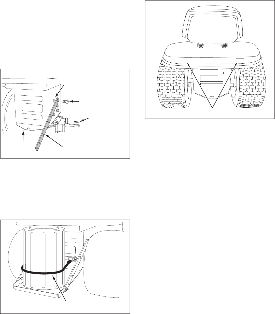
REAR REFLECTORS (QQ)
ATTACH REFLECTORS TO REAR FENDER
STEP 65: (SEE FIGURE 63)
• Ifyourtractorisnotequippedwithrearreectors,
assemblethesuppliedrearreectors(QQ)totherear
fender.Placethereectorsasclosetothebottomof
the fender and as far apart as the shape of the fender
will allow.
FIGURE 63
ATTACHING KEG TO WEIGHT TRAY
STEP 64: (SEE FIGURE 62)
• Place the plastic keg on the weight tray and ll with
approximately 75 lbs. of dry sand.
• Securethekegwiththerubbertarpstrap(FF)hooked
into the holes in the cross brace.
FIGURE 62
TARP STRAP (FF)
FIGURE 61
3/8" x 1" SLOTTED
TRUSS HEAD BOLT (J)
SQUARE KEY
SIDE BRACE
HOLE WITH HEX
BOLT REMOVED
TRACTOR
HITCH
ALTERNATE INSTRUCTIONS FOR WEIGHT TRAY
STEP 63: (SEE FIGURE 61)
• Blockuptherearofthetractortoallowremovalof
rear wheels.
• Removetherearwheelsfromtheaxle,retainingthe
square key and all other parts for reassembly.
• Removethehexboltfromthetopholeinthesideof
the tractor frame. If no bolt is present and the hole is
unthreaded, screw a 3/8" x 3/4" self threading bolt (H)
into and out of the hole to create threads.
• Assemblethenotchedendofeachsidebracetothe
top hole in the each side of the tractor frame, using a
3/8-16 x 1" slotted truss head bolt (J) for each brace.
• Assembletheweighttraytothesidebracesas
instructed in step 60 or 62 on pages 24 and 25.
• Reassemblethewheelsontotheaxle,makingsureto
reassemble the square keys and all other parts which
wereremoved.
27
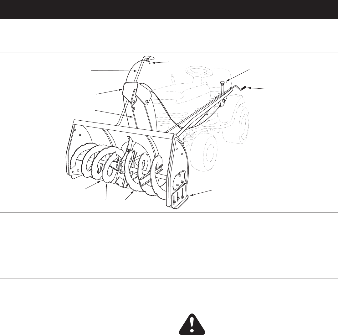
OPERATION
KNOW YOUR SNOW THROWER
Read this owner's manual and safety rules before operating your snow thrower.
Comparetheillustrationbelowwithyoursnowthrowertofamiliarizeyourselfwiththevariouscontrolsandtheirlocations.
CHUTE TILT HANDLEPivotstheUpperChuteupor
down to control the angle and distance of discharge.
CRANK ROD Rotates the Lower and Upper Chutes to
control the direction of discharge.
LIFT HANDLE Used to lift or lower the snow thrower
to transport or operating position.
LIFT RELEASE TRIGGER Releases the lock which
holds the snow thrower in the transport position
UPPER AND LOWER DISCHARGE CHUTE Controls
direction and height of snow discharge.
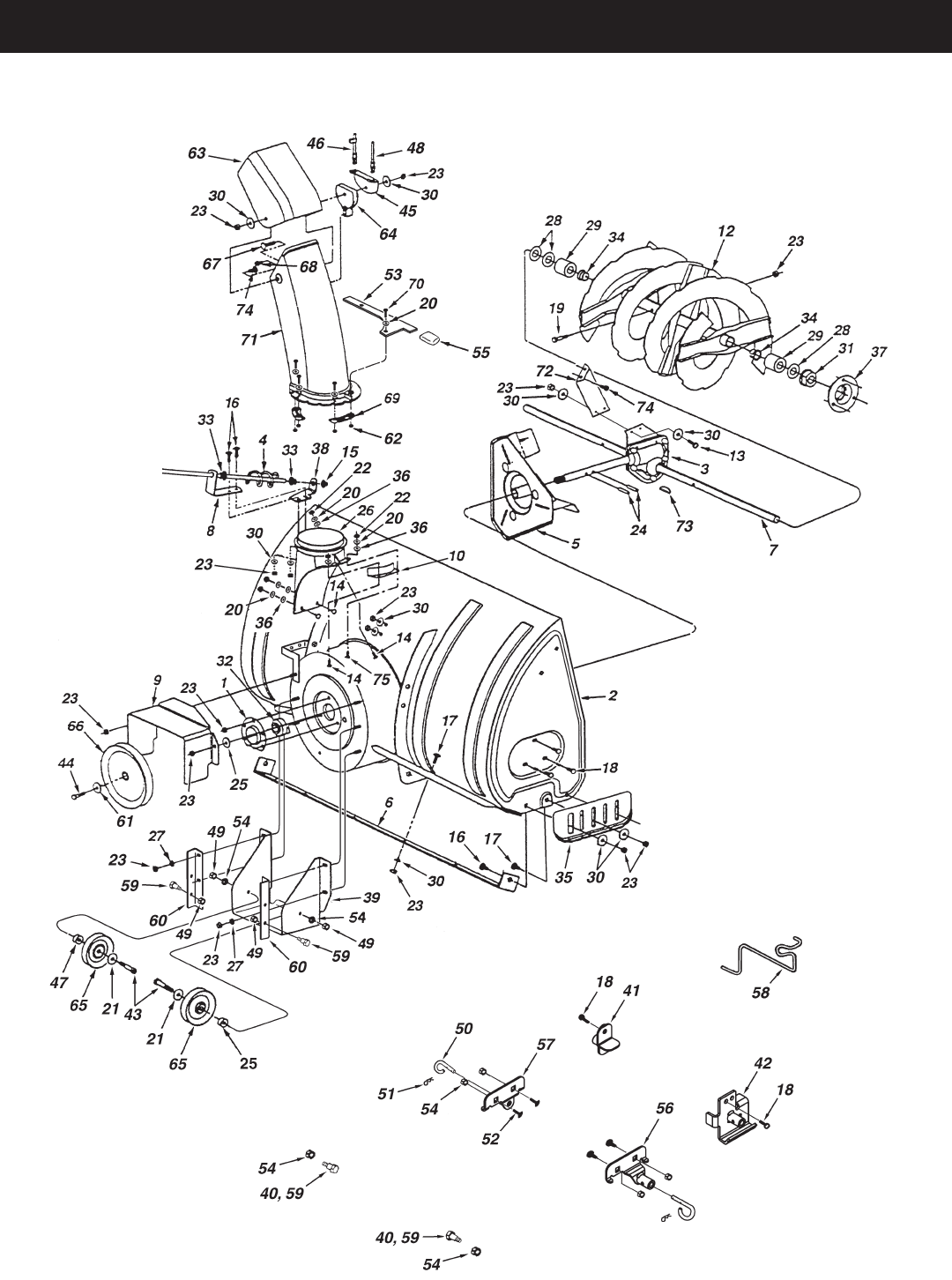
SCRAPER PLATE Replaceable plate that absorbs
wear and impact from contact with ground.
SKID SHOE Controls amount of clearance between
the scraper plate and the ground.
SPIRAL AUGER, R.H. & L.H. Feed snow to the
impeller fan at the center of the housing.
BEFORE STARTING
• Usetheendofassemblychecklisttoverifythatall
instructionshavebeenproperlycompleted.
• Makesuretheskidshoesareadjustedtomaintain
adequate ground clearance between the snow
thrower and the type of surface to be cleared. (Refer
totheServiceandAdjustmentssection.)
• Makesurethetractorenginehasthecorrectoil
for winter operation (SAE 5W-30). Refer to tractor
owner'smanual.
HOW TO START YOUR SNOW THROWER
• The tractor should be sitting with the engine running
atfullthrottle.Movetheattachmentclutchtothe
engaged position, starting the snow thrower before
the tractor clutch is engaged.
HOW TO STOP YOUR SNOW THROWER
• Tostopthesnowthrower,disengagethetractor's
attachmentclutchleverformanualclutchesorthe
clutch switch for electric clutches. Refer to your tractor
owner'smanual.
CAUTION: Never direct discharge
towards bystanders or windows. Do not
allow anyone in front of unit.
CONTROLLING SNOW DISCHARGE
• Tocontrolthedirectionsnowisthrown,thedischarge
chute has 180 degrees of rotation. Turn the crank rod
clockwise to rotate the chute to the right. Turn the
crank rod counterclockwise to rotate the chute to the
left.
• Tocontrolthedistancesnowisthrown,theupper
sectionofthedischargechutepivotsupanddown.
Pushforwardonthechutetilthandletopivotthe
chute down, decreasing the distance snow is thrown.
Pullbackonthehandletopivotthechuteup,
increasing the distance snow is thrown.
HOW TO USE YOUR SNOW THROWER
LIFT HANDLE
LIFT RELEASE TRIGGER
CRANK ROD
CHUTE TILT HANDLE
UPPER CHUTE
LOWER CHUTE
SPIRAL AUGERS, R.H. & L.H.
SKID SHOE
SCRAPER PLATE
28
RAISING AND LOWERING
• Toraise,pushdownonthelifthandleuntilthesnow
thrower locks in the raised transport position.
• Tolower,pushdownslightlyonthelifthandleandpull
the trigger. With the trigger pulled, slowly lower the
snow thrower until it reaches the ground.
CUSTOMER RESPONSIBILITIES
• Readandfollowthemaintenancescheduleandthemaintenanceprocedureslistedinthissection.
ServiceDates
Check for loose fasteners X
Check scraper and shoes for wear X X
Cleaning X
Lubrication Section X
MAINTENANCE SCHEDULE
Fill in dates as you
completeregularservice.
Before each use
After each use
Everyseason
Before storage
LUBRICATION
• Oilallpivotpointsonthesnowthrower.
• Oilthepivotpointsofthetwoidlerarmsontheclutch/
idler assembly.
• Applypenetratingoiltothecontrolcablesofthe
discharge chute.
• Applyagoodgradeofspraylubricanttothetrigger
assembly and the chute tilt control assembly.
CAUTION: Do not operate the snow
thrower without the rear weight attached
tothetractortoprovideextratractionand
stability.
MAINTENANCE
CHECK SCRAPER AND SHOES FOR WEAR
(Refer to gures 64 and 65 on page 29.)
• Thescraperplateandskidshoesonthebottomofthe
snowthroweraresubjecttowear.Topreventdamage
to the spiral auger housing, replace plate and shoes
beforewearisexcessive.
REMOVING SNOW
Snowremovalconditionsvarygreatlyfromlightuffy
snowfalltowetheavysnow.Operatinginstructionsmust
beexibletottheconditionsencountered.Theoperator
must adapt the lawn tractor and snow thrower to depth of
snow, wind direction, temperature and surface conditions.
• Beforebeginningoperation,thoroughlyinspectthe
areaofoperationandremovealldoormats,sleds,
boards, wires and other foreign objects.
• Thespiralaugerspeedisdirectlyrelatedtoengine
speed.Formaximumsnowremovalanddischarge,
maintainhighenginer.p.m.(fullthrottle).Itisadvisable
to operate the lawn tractor at a slow ground speed
(1stgear)forsafeandefcientsnowremoval.
• Indeep,driftedorbankedsnowitwillbenecessaryto
use full throttle and a slow ground speed (1st gear).
Driveforwardintothesnow,depressthetractor's
clutch-brake pedal and allow the spiral auger to clear
the snow. Repeat this method until a path is cleared.
Onthesecondpass,overlaptherstenoughtoallow
the snow thrower to handle the snow without repeated
stopping and starting of forward motion.
• Inextremelydeepsnow,raisethesnowthrowerfrom
thegroundtoremovethetoplayeranddriveforward
only until the tractors front tires reach the uncleared
bottomlayerofsnow.Depressthetractor'sclutch-
brake pedal and allow the spiral auger to clear the
snow.Reversethetractorandlowerthesnowthrower
totheground.Drivethetractorforwarduntilthesnow
again becomes too deep. Repeating this process into
andoutofdriftswilleventuallycleareventhedeepest
of snow piles.
• Ifthesnowthrowerbecomescloggedwithsnowor
jammed with a foreign object, disengage the snow
thrower immediately and shut off the tractor engine.
Unclog the snow thrower before resuming operation.
OPERATING TIPS
• Dischargesnowdownwindwheneverpossible.
• Tohelppreventsnowfromstickingtothesnowthrower,
allow the snow thrower to reach outdoor temperature
before using it. A light coat of wax may also be applied
to the inside surface of the snow thrower housing and
discharge chute.
• Usetirechainstoimprovetraction.
• Userearwheelweightstoimprovetraction.
• Beforetherstsnowfall,removeallstones,sticksand
other objects which could become hidden by the snow.
Permanentobstaclesshouldbemarkedforvisibility.
• Overlap each pass slightly to assure complete snow
removal.
DANGER: Shut off engine and
disengage snow thrower before
unclogging discharge chute. Unclog using
a wooden stick, not your hands.
29
SERVICE AND ADJUSTMENTS
CAUTION: Beforeservicingoradjusting
thesnowthrower,shutofftheengine,remove
the spark plug wire(s), set the parking brake
andremovethekeyfromthetractorignition.
FIGURE 65
FIGURE 64
REPLACING AUGER BELT
• Disengagethetractor'sattachmentclutch.
• Lowerthesnowthrowertotheground.
• Removetheattachmentpin.
• Lockthesnowthrower'slifthandleinthedown
position to decrease belt tension.
• Releasethespringtensionfromtheaugerbeltidler
arm on the bottom of the clutch/idler assembly.
• Removetheaugerdrivebeltfromtheclutch/idler
assembly and from the spiral auger housing.
• Installnewbeltovertopoflargeaugerdrivepulley
and under the two side idler pulleys. Twist the belt 1/4
turntoseatthe"V"ofthebeltinthegrooveofeach
idler pulley. Refer to gure55onpage23.
• Assemblethebeltontotheclutch/idlerassembly.
SKID SHOE ADJUSTMENT
• Theskidshoesaremountedoneachsideofthespiral
auger housing. They regulate the distance the scraper
plateisraisedabovetheplowingsurface.When
removingsnowfromagraveldrivewayoranduneven
surface,itisadvisabletokeepthescraperplateas
highabovethesurfaceaspossibletopreventpossible
damage to the spiral auger. On blacktop or concrete
surface, keep the scraper plate as close to the surface
as possible.
• Raisethesnowthroweroffthegroundandplacea
block under each end of the scraper plate. Loosen the
six hex nuts securing the skid shoes to the housing.
Adjust the skid shoes up or down and retighten the
nuts securely. Adjust both skid shoes to the same
heighttokeepthehousingandthescraperplatelevel.
Seegure64.
LIFT RELEASE CABLE ADJUSTMENT
• Iftheliftroddoesnotlockthesnowthrowersecurely
in the transport position, loosen the upper hex nut on
the lift bracket a few turns and tighten the lower hex
nut.Refertogure48onpage21.
• Iftheliftrodfailstounlockcompletelytolowerthe
snow thrower, loosen the lower hex nut on the lift
bracket a few turns and tighten the upper hex nut.
Refertogure48onpage21.
CLUTCH DISENGAGEMENT ADJUSTMENT
(For tractors with engagement rod clutches only.
Not for electric clutches or cable clutches)
If the spiral auger on the snow thrower does not stop
whentheattachmentclutchleveronthetractoris
disengaged, then adjustment is necessary. Proceed as
follows.Referbacktogure33onpage16.
• Placetheattachmentclutchleverinthedisengaged
position.
• Removethehairpincotterfromtheengagementrod
trunnion and lift the trunnion out of the hole in the idler
arm.
• Screwthetrunnionafewturnstowardsthefrontend
of the rod.
• Replacethetrunnionintotheholeintheidlerarmand
secure it with the hairpin cotter.
Check the operation of the snow thrower. If the spiral
augersstilldonotstop,repeattheabovestepsuntil
theaugersstopwhentheattachmentclutchleveris
placed in the disengaged position.
SPIRAL AUGERS
• Thespiralaugersaresecuredtotheaugershaftwith
two shear bolts and nylock nuts. If you hit a foreign
object or if ice jams the augers, the snow thrower is
designed so that the bolts will shear.
• Iftheaugerswillnotturn,checktoseeiftheshear
boltshavesheared.Seegure65.Tworeplacement
shearboltsandnylocknutshavebeenprovidedwith
the snow thrower. For future use order part number
710-0890A shear bolt and number 47810 nylock nut.

30
PARTS TO REMOVE AT END OF SEASON
• Removetheclutch/idlerassembly.(Thetwohanger
brackets and the two shoulder bolts may be left
attached to the tractor frame.)
• Removethedrivebeltfromtheenginepulley.
• Ifyoureplacedtheenginepulleykeeperonamanual
attachmentclutchtractor,reinstallthetractor'soriginal
enginepulleykeeper.Seegure33onpage16or
gure39onpage18.
• Ifyouhavearodoperatedattachmentclutch,remove
theengagementrodfromthetractor'sclutcharm.See
gure29onpage15.
• Ifarearmountedattachmentistobeused,remove
therearweighttray,leavingtheboltsthatyouinstalled
in the sides of the tractor draw bar. Retighten the
bolts.
• Ifafrontmountedattachmentistobeused,remove
the side plates from the tractor. Be sure to assemble
bolts back into the empty holes in the tractor frame.
STORAGE RECOMMENDATIONS
• Lowerthesnowthrowertotheground.
• Removethesnowthrowerfromthetractor.
• Cleanthesnowthrowerthoroughly.Washoffanysalt
depositwhichmayhavedriedonthethrowerand
housing.
• Anybaremetalthathasbecomeexposedshouldbe
paintedorcoatedwithalightoiltopreventrust.
• Storeinadryplace.
REMOVING THE SPIRAL AUGER HOUSING
• Lowerthesnowthrowertotheground.
• Removetheattachmentpin.Seegure54onpage
23.
• Lockthesnowthrower'slifthandleinthedown
position to decrease belt tension.
• Releasethespringtensionfromtheaugerbeltidler
arm on the bottom of the clutch/idler assembly.
• Removetheaugerdrivebeltfromtheclutch/idler
assembly.Seegure56onpage23.
• Pullthespiralaugerhousingassemblyoffofthe
tractor.
CAUSEPROBLEM CORRECTION
Clogged discharge chute
Spiralaugersdon'tturn
Snow thrower stalls tractor engine
TROUBLESHOOTING
STORAGE
1. Upper or lower V belt too loose 1. Increase tension on V belt
2. Upper or lower V belt broken 2. Replace V belt
3. Shear bolts are sheared. 3. Replace shear bolts
1. Tractor ground speed too fast 1. Use lower tractor gear
2. Tractor throttle set too low 2. Increase to full throttle
3. Snow too deep 3. Raise the snow thrower
4. Snow melts during contact with 4. Allow snow thrower to cool to
the snow thrower outdoor temperature before using
Front wheels slide instead of steering
Snowthrowerridesupoversnow
1. Object jammed in spiral auger 1. Stop engine, disengage the snow
thrower clutch and clear the auger
2.Hardorheavysnow 2.Increasetofullthrottleand
decrease ground speed
Not enough traction at front wheels 1. Increase scraper plate clearance
by lowering skid shoes
2. Pull down on lift handle to
increase weight on front wheels
1. Tractor ground speed too fast 1. Reduce ground speed
2. Bottom snow is icy or hard packed 2. Lower the skid shoes so that front
of skid shoe is lower than the rear

31
NOTES

32
NOTES

33
NOTES
34
PARTS
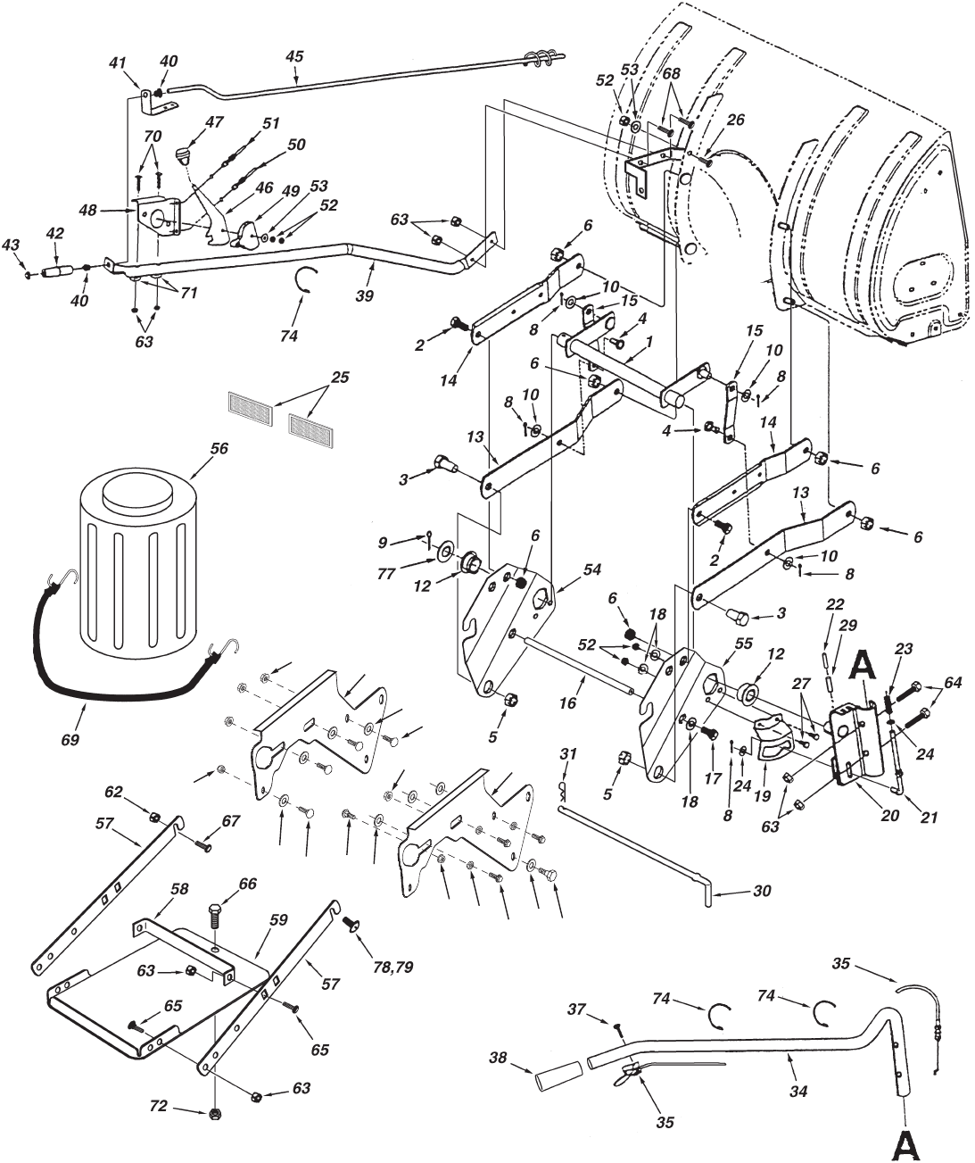
REPAIR PARTS FOR MODEL 486.248381 42" SNOW THROWER

35
REPAIR PARTS FOR MODEL 486.248381 42" SNOW THROWER
REF. PART QTY. DESCRIPTION
NO. NO.
1 05931 1 Housing, Bearing
2 65701 1 Housing Assembly
3 71464 1 Gear Assembly
4 63579 1 Chute Crank Rod Assembly
5 63768 1 Impeller Assembly
6 24773 1 Scraper Plate
7 25982 1 Shaft, Auger Gearbox
8 703-2735A 1 Bracket, Chute Crank
9 24816 1 Cover,Belt
10 705-5226 1 Chute Reinforcement
11 705-5269 1 Spiral Assembly, L.H. (not shown)
12 705-5270 1 Spiral Assembly, R.H.
13 43840 2 Hex Bolt, 5/16-18 x 1-1/4" Lg.
14 44950 4 Carriage Bolt, 1/4-20 x 3/4"
15 44917 1 Palnut, 3/8"
16 44326 4 Carriage Bolt, 5/16-18 x 1" Lg.
17 43080 10 Carriage Bolt, 5/16-18 x 3/4" Lg.
18 46703 8 Bolt, Self-Tap 5/16" x 3/4"
19 710-0890A 2 Bolt, Shear 5/16-18 x 1-1/2"
20 43088 11 Washer, 1/4"
21 43070 2 Washer, 3/8"
22 47189 5 Hex Nut, 1/4-20 Nylock
23 47810 29 Hex Nut, 5/16-18 Nylock
24 715-0114 2 Spiral Pin, 1/4" x 1-1/2" Lg.
25 750-0437 2 Bushing
26 731-1379A 1 Chute Adapter
27 43086 4 Lock Washer, 5/16"
28 736-0188 6 Washer, .76" x 1.49" x .06"
29 711-0469 4 Spacer, .75 ID x 1.25 OD x .5 L
30 43081 24 Washer, 5/16" Std. Wrt.
31 47615 2 Bearing, Flange
32 741-0309 1 Bearing, Ball
33 741-0475 2 Bushing, Plastic 3/8"
34 741-0493A 4 Bearing, Split, 3/4"
35 24279 2 Skid Shoe
36 48015 5 Washer, Nylon
37 784-5618 2 Housing, Bearing
38 24393 1 Bracket, Chute Crank
REF. PART QTY. DESCRIPTION
NO. NO.
39 24281 1 Bracket, Idler
40 49933 2 Shoulder Bolt, Round Head
41 65367 1 Hanger Bracket Assembly, L.H.
42 65450 1 Hanger Bracket Assembly, R.H.
43 41576 2 Hex Bolt, 3/8-16 x 1-3/4"
44 44377 1 Hex Bolt, 3/8-24 x 1"
45 784-5594 1 Bracket, Cable
46 746-0929 1 Cable, Chute Control With Clip
47 711-0242 1 Spacer
48 746-0928 1 Cable, Chute Control
49 HA21362 4 Hex Nut, 3/8-16 Nylock
50 43038 2 Pin,PivotLock
51 43343 2 Pin,HairCotter#4(1/8")
52 43350 4 Carriage Bolt, 3/8-16 x 1"
53 24394 1 Bracket, Chute Anti-rotation
54 47572 6 Hex Lock Nut, 3/8-16 Flanged
55 1643-60 1 Plastic Cap
56 64452 1 Hanger Bracket Assembly, R.H.
57 64451 1 Hanger Bracket Assembly, L.H.
58 47043 1 Keeper, Engine Pulley
59 48106 4 Bolt, Shoulder
60 24466 2 Bracket, Down Stop
61 736-0247 1 Washer,
62 47598 6 Hex Lock Nut, 1/4" Flanged
63 731-0921 1 Chute, Upper
64 731-1313C 1 Guide, Cable
65 47044 2 Pulley, V Type 4"
66 47026 1 Pulley, V Type
67 43085 1 Hex Bolt, 5/16-18 x 1-1/2"
68 710-0896 1 Screw, 1/4-14 x 5/8"
69 731-0851A 3 Chute Keeper
70 43661 6 Hex Bolt, 1/4-20 x 1"
71 731-1300C 1 Chute, Lower
72 25937 1 Center Brace, Gearbox
73 HA20185 1 #61WoodruffKey
74 43182 3 Hex Bolt, 5/16-18 x 3/4"
75 40504 1 ElevatorBolt,1/4-20x1"
40242 1 Owner'sManual
36
REPAIR PARTS FOR MODEL 486.248381 42" SNOW THROWER
73
36
60
76 61
65 75
62
11
65
75
75
62
63
32
33

37
REF. PART QTY. DESCRIPTION
NO. NO.
1 64637 1 Lift Shaft Assembly
2 710-0865 2 Hex Bolt, 1/2-13 x 1"
3 710-0367 2 Hex Bolt, 5/8-11 x 1-1/2"
4 711-0332 2 Pin, Bracket Lift
5 712-0261 2 Nut, Hex Lock 5/8-11 Thread
6 43262 6 Nut, Hex Lock 1/2-13
8 142 5 Pin, Cotter 1/8" x 3/4"
9 43093 1 Pin, Cotter 1/8" x 1-1/2"
10 R19171616 4 Washer, 17/32" x 1"
11 43350 6 Carriage Bolt, 3/8-16 x 1"
12 741-0192 2 Bearing, Flange With Flats
13 783-0380 2 Link, 15.80" Long
14 783-0381 2 Link, 11.75" Long
15 24476 2 Link, 4.88" Long
16 24311 1 Rod, Spacer
17 47599 2 Hex Bolt, 5/16-18 x 1" (Locking)
18 43086 4 Lock Washer, 5/16"
19 24820 1 Bracket, Lift
20 63773 1 Assembly, Handle Lift Bracket
21 48049 1 Rod, Index Lift
22 47369 1 Pin, Spring 3/16" x 1-3/4"
23 732-0306 1 Spring, Compression
24 R19131316 2 Washer, 13/32" x 13/16"
25 47788 2 Reector,Rear
26 43080 1 Carriage Bolt, 5/16-18 x 3/4"
27 43182 2 Hex Bolt, 5/16-18 x 3/4"
29 47368 1 Pin, Spring 5/16" x 1-3/4"
30 46954 1 Pin, Attachment
31 43343 1 Pin,Haircotter#4(1/8")
32 25678 1 Plate, Side (R.H.)
33 25679 1 Plate, Side (L.H.)
34 49916 1 Tube, Lift Handle
35 49912 1 Trigger and Lift Cable Assembly
36 43070 2 Washer, 3/8"
37 710-1233 1 Screw,Oval#10-24x1"
38 46446 1 Grip, Handle
39 47027 1 Tube, Crank Rod Support
40 741-0475 2 Bushing, 3/8" Plastic
REF. PART QTY. DESCRIPTION
NO. NO.
41 703-2735A 1 Bracket, Chute Crank
42 720-0201A 1 Knob, Crank
43 44917 1 Palnut, 3/8"
45 63579 1 Assembly, Chute Crank Rod
46 784-5604A 1 Handle, Chute Tilt
47 720-04039 1 Knob
48 603-0302 1 Assembly, Chute Tilt Bracket
49 731-1313C 1 Guide, Cable
50 746-0928 1 Cable, Chute Control
51 746-0929 1 Cable, Chute Control with Clip
52 43064 5 Nut, Hex Lock 5/16-18
53 43081 2 Washer, 5/16"
54 24285 1 Plate, Mounting (L.H.)
55 24284 1 Plate, Mounting (R.H.)
56 47093 1 Keg, Plastic
57 23812 2 Brace, Side (Weight Tray)
58 24288 1 Brace, Cross (Weight Tray)
59 25723 1 Tray, Weight
60 47631 6 Hex Bolt, 3/8-16 x 1" Self Tap
61 43003 6 Lock Washer, 3/8"
62 47572 8 Nut, Flanged Lock 3/8-16
63 47810 12 Nut, Nylock Hex 5/16-18
64 43084 2 Hex Bolt, 5/16-18 x 1-3/4"
65 44326 6 Carriage Bolt, 5/16-18 x 1"
66 43351 1 Hex Bolt, 1/2-13 x 1-1/4"
67 43001 2 Bolt, Hex 3/8-16 x 1"
68 43682 2 Carriage Bolt, 5/16-18 x 1-1/4"
69 43790 1 Strap, Tarp 25" Long
70 44215 2 Carriage Bolt, 5/16-18 x 1-3/4"
71 44695 2 Washer, Bowed
72 712-3083 1 Nut, Nylock Hex 1/2-13
73 48106 2 Bolt, Shoulder
74 726-0178 3 Tie, Nylon
75 R19172410 8 Washer, 1/2"
76 46584 1 Nut, Whizlock, 5/16-18
77 43601 1 Washer, 1.59" x 1.032" x .060"
78 49948 2 Bolt, Hex 3/8-16 x 3/4" Self Thd.
79 47361 2 Slotted Truss Hd. Bolt, 3/8-16 x 1"
REPAIR PARTS FOR MODEL 486.248381 42" SNOW THROWER
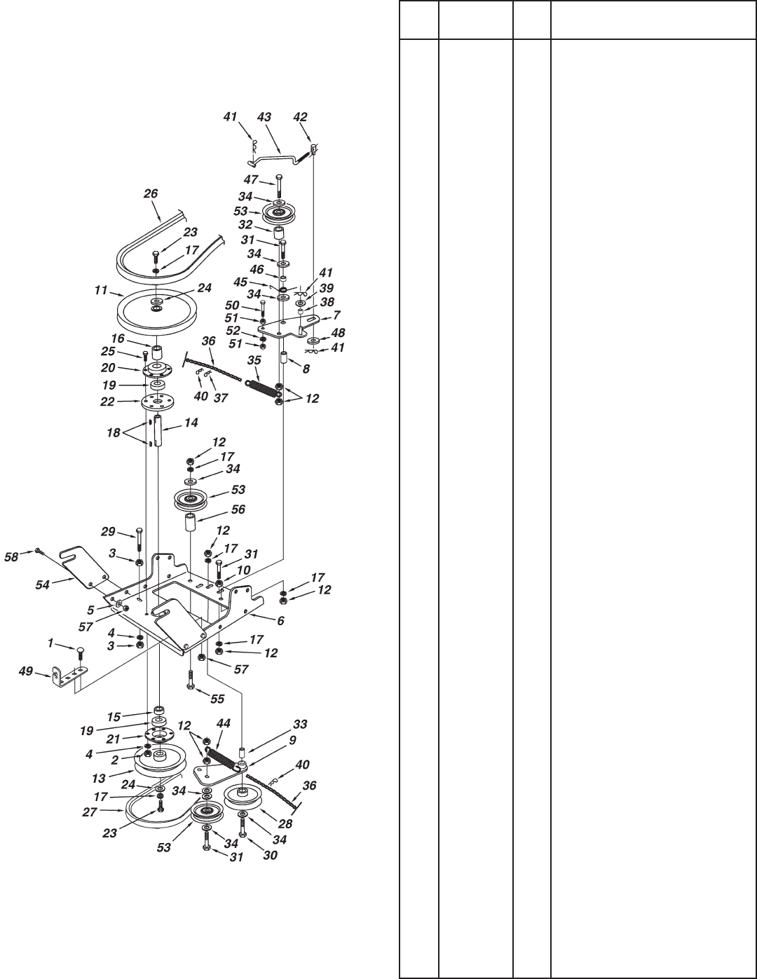
38
REPAIR PARTS FOR MODEL 486.248381 42" SNOW THROWER
REF. PART QTY. DESCRIPTION
NO. NO.
1 43080 2 Carriage Bolt, 5/16-18 x 3/4"
2 43064 3 Hex Lock Nut, 5/16-18
3 43083 2 Hex Nut, 5/16-18
4 43086 4 Lock Washer, 5/16"
5 43081 4 Washer, 5/16" Std. Wrt.
6 25727 1 Frame, Clutch and Pulley
7 63904 1 Idler Arm Assembly
8 24286 1 Spacer,Pivot
9 63762 1 Idler Bracket Assembly
10 43015 1 Hex Nut, 3/8-16
11 46981 1 Pulley, V Type 9"
12 43082 8 Nut, Hex Lock, 3/8-16
13 46982 1 Pulley, V Type 5-1/2"
14 738-0680 1 Shaft
15 750-0456 1 Spacer
16 750-0660 1 Spacer
17 43003 6 Lock Washer, 3/8"
18 714-0161 2 Key
19 741-0919 2 Bearing, Ball
20 08253B 1 Housing, Bearing
21 15296A 1 Housing, Open Bearing
22 14088B 1 Spacer, Spindle
23 44377 2 Hex Bolt, 3/8-24 x 1"
24 736-0247 2 Washer
25 43063 3 Hex Bolt, 5/16-18 x 1"
26 46989 1 Belt,VTypeDrive(55")
48138 1 Belt,VTypeDrive(56")
27 47846 1 Belt, V Type Auger
28 47044 1 Pulley, V Type 4"
29 47025 1 Hex Bolt, 5/16-18 x 3-1/2"
30 43432 1 Hex Bolt, 3/8-16 x 2-1/2"
31 43054 3 Hex Bolt, 3/8-16 x 2"
32 24571 1 Spacer
33 24472 1 Spacer,Pivot
34 43070 8 Washer, 3/8"
35 46959 1 Spring
36 46963 2 Chain
37 43055 1 Pin, Hair Cotter, 3/32"
38 23727 1 Spacer
39 43088 1 Washer, 1/4"
40 43343 2 Pin,HairCotter#4(1/8")
41 47134 2 Pin, Hair Cotter 5/64"
42 711-0198 1 Trunnion
43 46948 1 Rod, Engagement
44 47620 1 Spring
45 47607 1 Spring, Torsion
46 23625 1 Spacer
47 43509 1 Hex Bolt, 3/8-16 x 2-3/4" Lg.
48 47605 1 Washer, Flat 3/8"
49 24558 1 Cable Bracket
50 49870 1 Hex Bolt, 1/4-20 x 2-1/2"
51 43178 2 Hex Nut, 1/4-20
52 43177 1 Lock Washer, 1/4"
53 48883 3 Pulley, Flat 3-5/8"
54 25728 2 Rear Pulley Frame Bracket
55 46938 1 Hex Bolt, 3/8-16 x 3-1/4"
56 25780 1 Spacer
57 47810 6 Hex Nut, 5/16-18 Nylock
58 43182 4 Hex Bolt, 5/16-18 x 3/4"
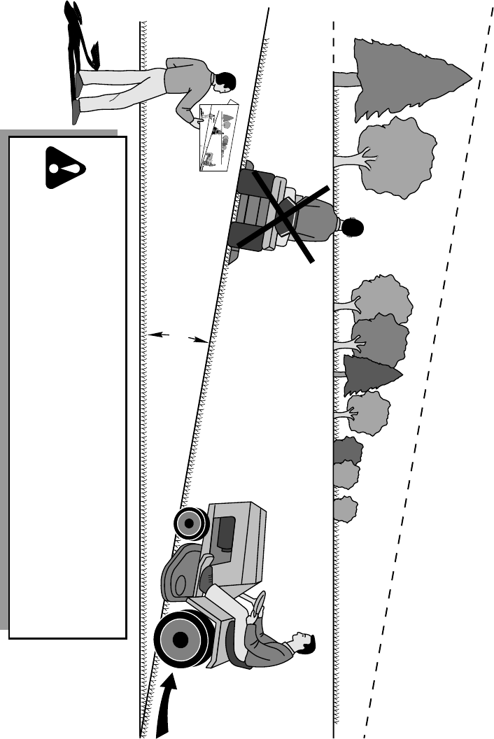
39
WARNING: To avoid serious injury, operate your tractor up and
down the face of slopes, never across the face. Do not operate
on slopes greater than 10 degrees. Make turns gradually to
prevent tipping or loss of control. Exercise extreme caution
when changing direction on slopes. Braking may be affected by
tractor attachment. Reduce speed on slopes.
1. Fold this page along dotted line indicated above.
2. Hold page before you so that its left edge is vertically parallel to a tree
trunk or other upright structure.
3. Sight across the fold in the direction of hill slope you want to measure.
4. Compare the angle of the fold with the slope of the hill.
ONLY RIDE UP AND DOWN HILL,
NOT ACROSS HILL
FO
LD
A
LON
G
D
O
T
TED LI
N
E
T
H
IS
I
S
A
1
0
DEG
R
E
E
SL
O
P
E
10 DEGREES MAX.
SUGGESTED GUIDE FOR SIGHTING SLOPES FOR SAFE OPERATION
OF TRACTOR WITH ATTACHMENT

® Registered Trademark / TM Trademark / SM Service Mark of Sears Brands, LLC
® Marca Registrada / TM Marca de Fábrica / SM Marca de Servicio de Sears Brands, LLC
MC Marque de commerce / MD Marque déposée de Sears Brands, LLC © Sears Brands, LLC
Get it fixed, at your home or ours!
Your Home
For repair – in your home – of all major brand appliances,
lawn and garden equipment, or heating and cooling systems,
no matter who made it, no matter who sold it!
For the replacement parts, accessories and
owner’s manuals that you need to do-it-yourself.
For Sears professional installation of home appliances
and items like garage door openers and water heaters.
1-800-4-MY-HOME®(1-800-469-4663)
Call anytime, day or night (U.S.A. and Canada)
www.sears.com www.sears.ca
For expert home solutions advice: www.managemyhome.com
Our Home
For repair of carry-in items like vacuums, lawn equipment,
and electronics, call or go on-line for the location of your nearest
Sears Parts & Repair Service Center
1-800-488-1222 (U.S.A.) 1-800-469-4663 (Canada)
Call anytime, day or night
www.sears.com www.sears.ca
To purchase a protection agreement on a product serviced by Sears:
1-800-827-6655 (U.S.A.) 1-800-361-6665 (Canada)
Para pedir servicio de reparación
a domicilio, y para ordenar piezas:
1-888-SU-HOGAR®
(1-888-784-6427)
Au Canada pour service en français:
1-800-LE-FOYERMC
(1-800-533-6937)
www.sears.ca
