Craftsman 572 61096 Users Manual
572610830 572610830 CRAFTSMAN ROTARY TOOL - Manuals and Guides L1005394 View the owners manual for your CRAFTSMAN ROTARY TOOL #572610830. Home:Tool Parts:Craftsman Parts:Craftsman ROTARY TOOL Manual
de5eff69-cdac-4c55-9617-653e6c720bd4 Craftsman Power Hammer 572.61095 User Guide |
2015-01-05
: Craftsman Craftsman-572-61096-Users-Manual-160984 craftsman-572-61096-users-manual-160984 craftsman pdf
Open the PDF directly: View PDF ![]() .
.
Page Count: 58
2610913327
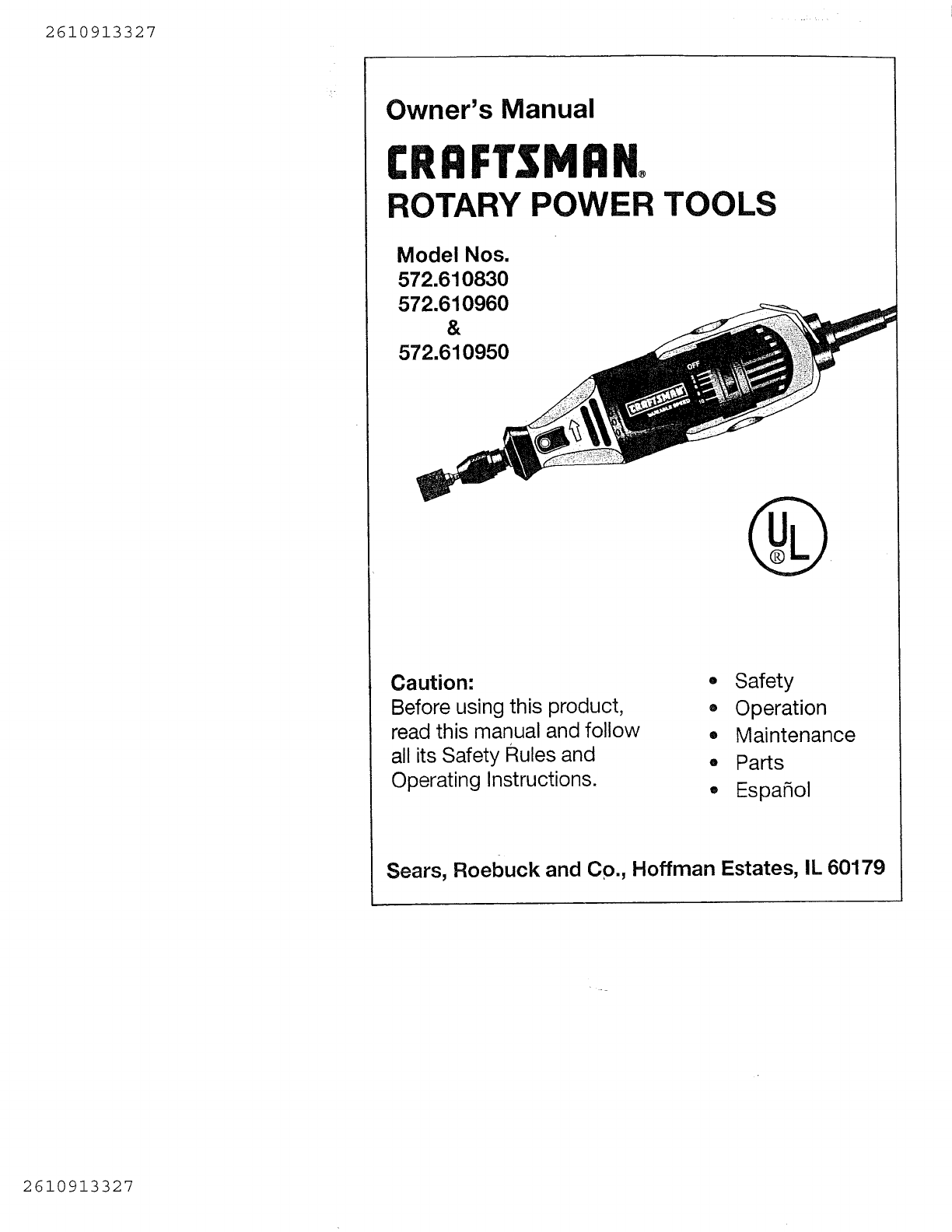
Owner's Manual
CRRFTSMRN
ROTARY POWER TOOLS
Model Nos.
572.610830
572.610960
&
572.610950
Caution:
Before using this product,
read this manual and follow
all its Safety Rules and
Operating Instructions.
•Safety
• Operation
° Maintenance
°Parts
°Espa_ol
Sears, Roebuck and Co., Hoffman Estates, IL 60179
2610913327

Table of Contents Page
Warranty ........................................................ 2
Power Tool Safety Rules .......................................... 3-6
Symbols ........................................................ 7
Functional Description and Specifications ............................ 8-9
Assembly .................................................... 10-11
Operating Instructions .......................................... 12-15
Assembly & Operation of Attachments ............................. 16-20
Maintenance ................................................. 21-22
Accessories .................................................. 23-25
Operating Speeds for Accessories ................................ 26-27
Service Parts ................................................. 28-31
Espa5ol ..................................................... 32-56
Sears Warranty
FullOne Year Warranty on Craftsman Rotary Power Tool
If this Craftsman Rotary Power Tool fails to give complete satisfaction within one
year from the date of purchase, Sears will replace it free of charge.
If this Rotary Power Tool is used for commercial or rental purposes, this warranty
applies for only one year from the date of purchase.
Warranty Service
Warranty service is available by returning this Craftsman Rotary Power Tool to your
nearest Sears Store in the United States.
This warranty applie_ only while this Rotary Power Tool is used in the United
States.
This warranty gives you specific legal rights, and you may also have other rights
which vary from state to state.
Sears, Roebuck and Co., Dept. 817WA, Hoffman Estates, IL 60179
Read and understand all instructions. Failure to follow all instructions
listed below, may result in electric shock, fire and/or serious personal injury.
SAVE THESE INSTRUCTIONS
Work Area
Keep your work area clean and well lit.
Cluttered benches and dark areas invite
accidents.
Do not operate power tools in explosive
atmospheres, such as in the presence of
flammable liquids, gases, or dust. Power
tools create sparks which may ignite the
dust or fumes.
Keep by-standers, children, and visitors
away while operating a power tool.
Distractions can cause you to lose control.
Electrical Safety
Double Insulated tools are equipped with
a polarized plug (one blade is wider than
the other.) This plug will fit in a polarized
outlet only one way. If the plug does not
fit fully in the outlet, reverse the plug. If it
still does not fit, contact a qualified
electrician to install a polarized outlet.
Do not change the plug in any way.
Double Insulation [] eliminates the need
for the three wire grounded power cord and
grounded power supply system. Before
plugging in the tool, be certain the outlet
voltage supplied is within the voltage
marked on the nameplate. Do not use "AC
only" rated tools with a DC power supply.
Avoid body contact with grounded
surfaces such as pipes, radiators, ranges
and refrigerators. There is an increased
risk of electric shock if your body is
grounded. If operating the power tool in
damp locations is unavoidable, a Ground
Fault Circuit Interrupter must be used to
supply the power to your tool. Electrician's
rubber gloves and footwear will further
enhance your personal safety.
Don't expose power tools to rain or wet
conditions. Water entering a power tool
will increase the risk of electric shock.
Do not abuse the cord. Never use the
cord to carry the tools or pull the plug
from an outlet. Keep cord away from
heat, oil, sharp edges or moving parts.
Replace damaged cords immediately.
Damaged cords increase the risk of electric
shock.
When operating a power tool outside,
use an outdoor extension cord marked
"W-A" or "W." These cords are rated for
outdoor use and reduce the risk of electric
shock. Refer to "Recommended sizes of
Extension Cords" in the Accessory section
of this manual.
Personal Safety
Stay alert, watch what you are doing and
use common sense when operating a
power tool. Do not use tool while tired or
under the influence of drugs, alcohol, or
medication. A moment of inattention while
operating power tools may result in serious
personal injury.
Dress properly. Do not wear loose
clothing or jewelry. Contain long hair.
Keep your hair, clothing, and gloves
away from moving parts. Loose clothes,
jewelry, or tong hair can be caught in
moving parts. Keep handles dry, clean and
free from oil and grease.
Avoid accidental starting. Be sure switch
is "OFF" before plugging in. Carrying
tools with your finger on the switch or
plugging in tools that have the switch "ON"
invites accidents.
Remove adjusting keys or wrenches
before turning the tool "ON". A wrench or
a key that is left attached to a rotating part
of the tool may result in personal injury.
Do not overreach. Keep proper footing
and balance at all times. Proper footing
and balance enables better control of the
tool in unexpected situations.
Use safety equipment. Always wear eye
protection. Dust mask, non-skid safety
shoes, hard hat, or hearing protection must
be used for appropriate conditions.
Tool Use and Care
Use clamps or other practical way to
secure and support the workpiece to a
stable platform. Holding the work by hand
or against your body is unstable and may
lead to loss of control.
Do not force tool. Use the correct tool for
your application. The correct tool will do
the job better and safer at the rate for which
it is designed.
Do not use tool if switch does not turn it
"ON" or "OFF". Any tool that cannot be
controlled with the switch is dangerous and
must be repaired.
Disconnect the plug from the power
source before making any adjustments,
changing accessories, or storing the
tool. Such preventive safety measures
reduce the risk of starting the tool
accidentally. Store idle tools out of reach
of children and other untrained persons.
Tools are dangerous in the hands of
untrained users.
Maintain tools with care. Keep cutting
tools sharp and clean. Properly
maintained tools, with sharp cutting edges
are less likely to bind and are easier to
control. Any alteration or modification is a
misuse and may result in a dangerous
condition.
Check for misaUgnment or binding of
moving parts, breakage of parts, and any
other condition that may affect the tools
operation. If damaged, have the tool
serviced before using. Many accidents are
caused by poorly maintained tools. Develop
a periodic maintenance schedule for your
tool.
Use only accessories that are
recommended by the manufacturer for
your model. Accessories that may be
suitable for one tool, may become
hazardous when used on another tool.
Service
Tool service must be performed only by
qualified repair personnel. Service or
maintenance performed by unqualified
personnel could result in a risk of injury. For
example: internal wires may be misplaced
or pinched, safety guard return springs may
be improperly mounted.
When servicing atool, use only identical
replacement parts. Follow instructions in
the Maintenance section of this manual.
Use of unauthorized parts or failure to
follow Maintenance Instructions may create
a risk of electric shock or injury. Certain
cleaning agents such as gasoline, carbon
tetrachloride, ammonia, etc. may damage
plastic parts.
Accessories must be rated for at least
the speed recommended on the tool
warning label. Wheels and other
accessories running over rated speed can
fly apart and cause injury.
Hold tool by insulated gripping surfaces
when performing an operation where the
cutting tool may contact hidden wiring or
its own cord. Contact with a "live" wire will
make exposed metal parts of the tool "live"
and shock the operator. If cutting into
existing walls or other blind areas where
electrical wiring may exist is unavoidable,
disconnect all fuses or circuit breakers
feeding this worksite.
The following warning is intended for flex
shaft tools and accessories: Do not
operate the flexible shaft with a sharp
bend. Over bending the shaft can generate
excessive heat on the jacket or hand piece.
The recommended minimum is 6" radius.
Always disconnect the power cord from
the power source before making any
adjustments or attaching any
accessories. You may unexpectedly cause
the tool to start leading to serious persohal
injury.
Be aware of the switch location, when
placing the tool down or when picking
the tool up. You may accidentally activate
the switch.
The following warning is intended for flex
shaft tools and accessories: Always hold
the hand piece firmly in your hands
during the start-up. The reaction torque of
the motor, as it accelerates to full speed,
can cause the shaft to twist.
Always hold the tool with two hands
during start-up. The reaction torque of the
motor can cause the tool to twist.
Always wear safety goggles and dust
mask. Use only in well ventilated area.
Using personal safety devices and working
in safe environment reduces risk of injury.
After changing the bits or making any
adjustments, make sure the collet nut
and any other adjustment devices are
securely tightened. Loose adjustment
device can unexpectedly shift, causing loss
of control, loose rotating components will
be violently thrown.
Do not reach in the area of the spinning
bit. The proximity of the spinning bit to your
hand may not always be obvious.
Allow brushes to run at operating speed
for at least one minute before using
wheel. During this time no one is to stand
in front or in line with the brush. Loose
bristles or wires will be discharged during
the run-in time.
Wire and bristle brushes must never be
operated at speeds greater than
15,000/min. Direct the discharge of the
spinning wire brush away from you.
Small particles and tiny wire fragments may
be discharged at high velocity during the
"cleaning" action with these brushes and
may become imbedded in your skin.
Bristles or wires will be discharged from the
brush at high speeds.
Wear protective gloves and face shield
with wire or bristle brushes. Apply wire
or bristle brushes lightly to the work as
only the tips of the wire/bristles do the
work. "Heavy" pressure on bristles will
cause the wire or bristle to become
overstressed, resulting in a wiping action
and will cause the bristles/wire to be
discharged.
Carefully handle both the tool and
individual grinding wheels to avoid
chipping or cracking. Install a new wheel
if tool is dropped while grinding. Do not
use a wheel that may be damaged.
Fragments from a wheel that bursts during
operation will fly away at great velocity
possibly striking you or bystanders.
Never use dull or damaged bits. Sharp
bits must be handled with care.
Damaged bits -can snap during use. Dull bits
require more force to push the tool,
possibly causing the bit to break.
Use clamps to support workpiece
whenever practical. Never hold a small
workpiece in one hand and the tool in the
other hand while in use. Allow for
sufficient space, at least 6", between
your hand and the spinning bit. Round
material such as dowel rods, pipes Or
tubing have a tendency to rol! while being
cut, and may cause the bit to "bite" or jump
toward you. Clamping a small workpiece
allows you to use both hands to control the
tool.
Inspect your workpiece before cutting.
When cutting irregularly shaped
workpieces, plan your work so it will not
slip and pinch the bit and be torn from
your hand. For example, if carving wood,
make sure there are no nails or foreign
objects in the workpiece. Nails or foreign
objects can cause the bit to jump.
Never start the tool when the bit is
engaged in the material. The bit cutting
edge may grab the material causing loss of
control of the cutter.
Avoid bouncing and snagging the wheel,
especially when working corners, sharp
edges etc. This can cause loss of control
and kick-back.
The direction of feed with the bit into the
material when carving, routing or cutting
is very important. Always feed the bit
into the material in the same direction as
the cutting edge is exiting from the
material (which is the same direction as
the chips are thrown). Feeding the tool in
the wrong direction, causes the cutting
edge of the bit to climb out of the work and
pull the tool in the direction of this feed.
If the workpiece or bit becomes jammed
or bogged down, turn the tool "OFF" by
the switch. Wait for all moving parts to
stop and unplug the tool, then work to
free the jammed material. If the switch to
the tool is left "ON" the tool could restart
unexpectedly causing serious perspnal
injury.
Do not leave a running tool unattended,
turn power off. Only when tool comes to a
complete stop it is safe to put it down.
Do not grind or sand near flammable
materials. Sparks from the wheel could
ignite these materials.
Do not touch the bit or collet after use.
After use the bit and collet are too hot to be
touched by bare hands.
Regularly clean the tool's air vents by
compressed air. Excessive accumulation
of powdered metal inside the motor housing
may cause electrical failures.
Do not allow familiarity gained from
frequent use of your rotary tool to
become commonplace. Always remember
that a careless fraction of a second is
sufficient to inflict severe injury.
Do not alter or misuse tool. Any alteration
or modification is a misuse and may result
in serious personal injury.
This product is not intended for use as a
dental drill, in human or veterinary
medical applications. Serious personal
injury may result.
When using the steel saws, cutoff
wheels, high speed cutters or tungsten
carbide cutters, always have the work
securely clamped. Never attempt to hold
the work with one hand while using any
of these accessories. The reason is that
these wheels will grab if they become
slightly canted in the groove, and can kick-
back causing loss of control resulting in
serious injury. Your second hand should be
used to steady and guide the hand holding
the tool. When a cutoff wheel grabs, the
wheel itself usually breaks. When the steel
saw, high speed cutters or tungsten carbide
cutter grab, it may jump from the groove
and you could lose control of the tool.
Some dust created by
power sanding, sawing,
grinding, drilling, and other construction
activities contains chemicals known to
cause cancer, birth defects or other
reproductive harm. Some examples of
these chemicals are:
•Lead from lead-based paints,
• Crystalline silica from bricks and cement
and other masonry products, and
• Arsenic and chromium from chemicaUy-
treated lumber.
Your risk from these exposures varies,
depending on how often you do this type of
work. To reduce your exposure to these
chemicals: work in awell ventitated area,
and work with approved safety equipment,
such as those dust masks that are specially
designed to filter out microscopic particles.

, II I
"T :O
IMPORTANT: Some of the following symbols may be used on your tool. Please study them
and learn their meaning. Proper interpretation of these symbols will allow you to operate the
tool better and safer.
Symbol Name Designation/Explanation
V Volts Voltage (potential)
A Amperes Current
Hz Hertz Frequency (cycles per second)
W Watt Power
kg Kilograms Weight
min Minutes Time
s Seconds Time
O Diameter Size of drill bits, grinding wheels, etc.
... nO No load speed Rotational speed, at no load
.../min Revolutions or reciprocation per minute Revolutions, strokes, surface speed,
orbits etc. per minute
0 Off position Zero speed, zero torque...
m
1,2, 3 .... Selector settings Speed, torque or position settings.
I, II, Ill, Higher number means greater speed
0_d Infinitely variable selector with off Speed is increasing from 0 setting
Arrow Action in the direction of arrow
Alternating current Type or a characteristic of current
===- Direct current Type or a characteristic of current
Alternating or direct current Type or a characteristic of current
[] Class II construction Designates Double Insulated
Construction tools.
(_) Earthing terminal Grounding terminal
/_ Warning symbol Alerts user to warning messages
Ni-Cad RBRC TM seal Designates Ni-Cad battery recycling
program
@
This symbol designates
that this tool is listed by
Underwriters Laboratories.
This symbol designates
that this tool is listed by
the Canadian Standards
Association.
0®
This symbol designates
that this tool is listed to
Canadian Standards by
Underwriters Laboratories.
Disconnect the plug from the power source before making any
assembly, adjustments or changing accessories, Such preventive
safety measures reducethe riskof starting the tool accidentally,
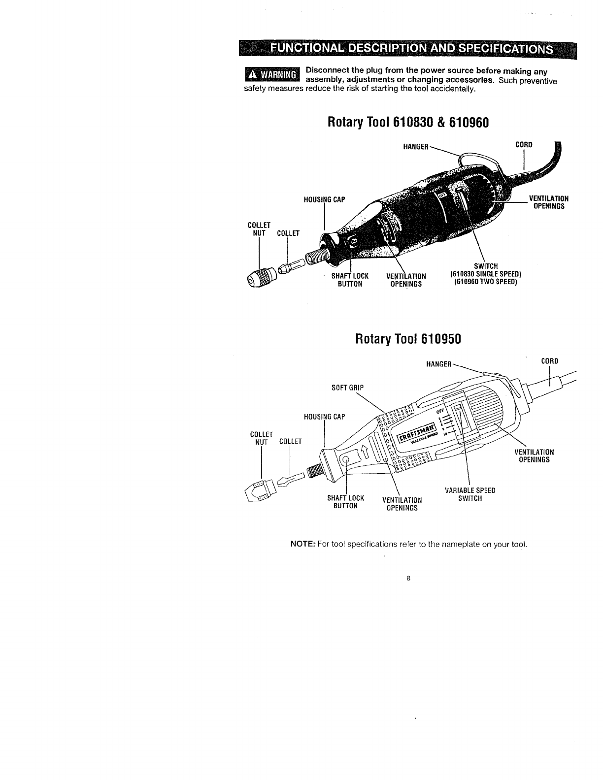
RotaryTool610830 & 610960
VENTILATION
HOUSING C_
OPENINGS
COLLET
NUT
_q SHAFT LOCK VENTILATION (610830 SINGLE SPEED)
BUTTON OPENINGS (610960 TWO SPEED)
RotaryTool610950
CORD
SOFT GRIP
COLLET
NUT
HOUSINGCAP
COLLET
VENTILATION
OPENINGS
SHAFTLOCK VENTILATION
BUII'ON OPENINGS
VARIABLESPEED
SWITCH
NOTE: For tool specifications refer to the nameplate on your tool.
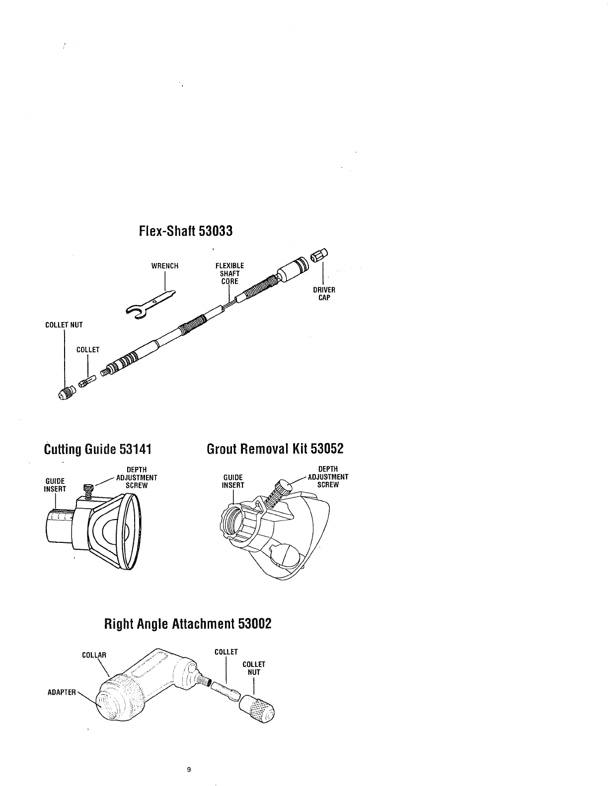
Flex-Shaft 53033
CuttingGuide53141 GroutRemovalKit53052
DEPTH DEPTH
GUIDE _ADJUSTMENT GUIDE _ _ ADJUSTMENT
INSiRT___ SCREW SCiEW
RightAngleAttachment53002
COLLAR _COLLET
\ __ ICO'LET
\ _"_ _ ,'_.',._ I NUT
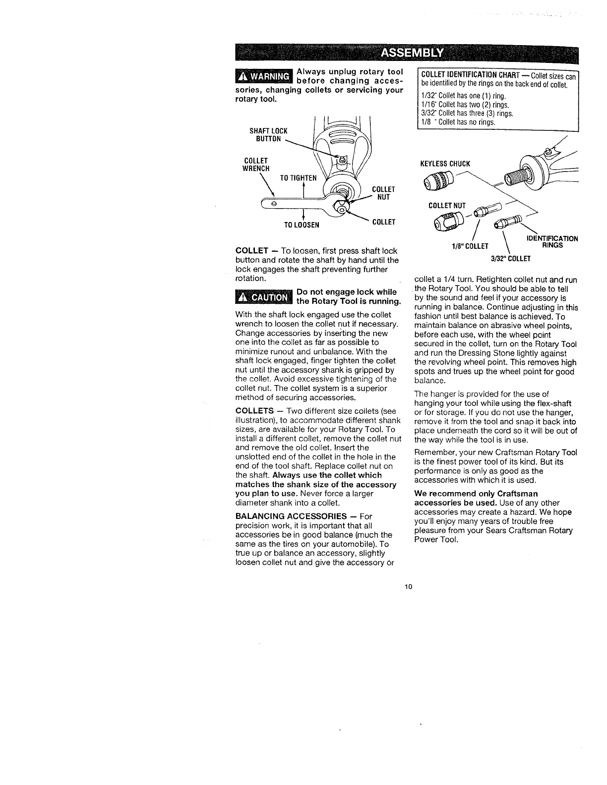
_Always unplug rotary tool
before changing acces-
sories, changing collets or servicing your
rotary tool.
I
SHAFTLOCK
BUTTON_
COLLET
WRENCH T COLLET
TOLOOSEN COLLET
COLLET -- To loosen, first press shaft lock
button and rotate the shaft by hand until the
lock engages the shaft preventing further
rotation.
Do not engage lock while
the Rotary Tool is running.
With the shaft lock engaged use the collet
wrench to loosen the collet nut if necessary.
Change accessories by inserting the new
one into the collet as far as possible to
minimize runout and unbalance. With the
shaft lock engaged, finger tighten the collet
nut until the accessory shank is gripped by
the collet. Avoid excessive tightening of the
collet nut. The collet system is a superior
method of securing accessories.
COLLETS -- Two different size collets (see
illustration), to accommodate different shank
sizes, are available for your Rotary Tool. To
install a different collet, remove the collet nut
and remove the old collet. Insert the
unslotted end of the collet in the hole in the
end of the tool shaft. Replace collet nut on
the shaft. Always use the collet which
matches the shank size of the accessory
you plan to use. Never force a larger
diameter shank into a collet.
BALANCING ACCESSORIES -- For
precision work, it is important that all
accessories be in good balance (much the
same as the tires on your automobile). To
true up or balance an accessory, slightly
loosen collet nut and give the accessory Or
COLLETIDENTIFICATIONCHART-- Colletsizes ca_
beidentified by the rings on thebackend of collet./
1/32" C0llet hasone (1) ring. |
1/16"C011ethastwo (2) rings. |
3/32" C011ethas three (3) rings. |
1/8 "Collet hasno rings. J
KEYLESSCHUCK
collet a 1/4 turn. Retighten collet nut and run
the Rotary Tool. You should be able to tell
by the sound and feel if your accessory is
running in balance. Continue adjusting in this
fashion until best balance is achieved. To
maintain balance on abrasive wheel points,
before each use, with the wheel point
secured in the collet, turn on the Rotary Tool
and run the Dressing Stone lightly against
the revolving wheel point. This removes high
spots and trues up the wheel point for good
balance.
The hanger is provided for the use of
hanging your tool while using the flex-shaft
or for storage. If you do not use the hanger,
remove it from the tool and snap it back into
place underneath the cord so it will be out of
the way while the tool is in use.
Remember, your new Craftsman Rotary Tool
is the finest power tool of its kind. But its
performance is only as good as the
accessories with which it is used.
We recommend only Craftsman
accessories be used. Use of any other
accessories may create a hazard. We hope
you'll enjoy many years of trouble free
pleasure from your Sears Craftsman Rotary
Power Toot.
lO
KEYLESS CHUCK -- The keyless chuck
holds various accessories with shank sizes
1/32" to !/8" and is intended for light duty
accessories such as drill bits, sanding
drums, polishing accessories, wire and
bristle brushes and cut-off wheels. The
keyless chuck allows you to change
accessories frequently, quickly and easily.
There are some applications which can
generate high forces on the bit or if you are
unable to generate finger tightening pressure
sufficient to secure the bit you must use the
supplied wrench to assist in securing the bit.
Attaching the Keyless Chuck and
Accessory Bit
Read and understand the
manual for use of the
keyless chuck with the tool. Insert and
securely tighten the shank of the
accessory well within the jaws of the
chuck. If an accessory is not properly
gripped within the jaws of a chuck it may
loosen and fly out during use possibly
striking you or bystanders.
To replace or attach the keyless chuck
accessory to your MultiPro rotary tool,
unplug the tool and engage the shaft lock
button then remove the collet and collet nut.
Thread the keyless chuck on the end of the
shaft. Engage the shaft lock button again,
insert the accessory shank into the chuck
and finger tighten until the shank is secure.
For small size drill bits, close the chuck to
the point where the bit will just fit in; then
tighten securely. This helps center the bit in
the keyless chuck correctly. In some high
force applications such as removing metal,
tile cutting or routing, the bit (tungsten
carbide cutters, high speed cutters, router
bits or tile cutters) and chuck will become
hot if overloaded for extended periods of
time. Overloading the chuck may cause the
bit to loosen and slip. It is recommended
that in these types of applications that the
bit be secured in the chuck with the supplied
wrench and work in intervals to allow cooling
of the bit and chuck. If the bit slips the tool
will begin to vibrate excessively, this is an
indication that you should shut the tool off,
re-position and tighten the bit then allow the
tool to run no-load for a few minutes to cool.
The chuck should be cleaned occasionally to
keep it functioning properly. Simply remove
the chuck from the tool and gently tap the
tip of the chuck on a fat surface to remove
any loose debris. In some applications the
keyless chuck may tighten up during use. If
this occurs, gently loosen using the wrench
included in your rotary tool kit.
11
The Rotary Tool is a handful of high-speed
power. It serves as a carver, grinder,
polisher, sander, cutter, power brush, drill
and more.
The Rotary Tool has a small, powerful
electric motor, is comfortable in the hand,
and is made to accept a large variety of
accessories including abrasive wheels, drill
bits, wire brushes, polishers, engraving
cutters, router bits, and cutting wheels.
Accessories come in a variety of shapes and
permit you to do a number of different jobs.
As you become familiar with the range of
accessories and their uses, you will learn just
how versatile the Rotary Tool is. You'll see
dozens of uses you hadn't thought of before.
The real secret of the Rotary Tool is its
speed. To understand the advantages of its
high speed, you have to know that the
standard portable electric drill runs at
speeds up to 2,800 revolutions per minute.
The Rotary Tool operates at speeds up to
35,000 revolutions per minute. The typical
electric drill is a low-speed, high torque tool;
the Rotary Tool is just the opposite - a high-
speed, low torque tool. The chief difference
to the user is that in the high speed tools,
the speed combined with the accessory
mounted in the collet does the work. You
don't apply pressure to the tool, but simply
hold and guide it. In the low speed tools, you
not only guide the tool, but also apply
pressure to it, as you do, for example, when
drilling a hole.
It is this high speed, along with its compact
size and wide variety of special accessories,
that makes the Rotary Tool different from
other power tools. The speed enables it to
do jobs low speed tools cannot do, such as
cutting hardened steel, engraving glad, etc.
Getting the most out of your Rotary Tool is a
matter of learning how to let this speed work
for you.
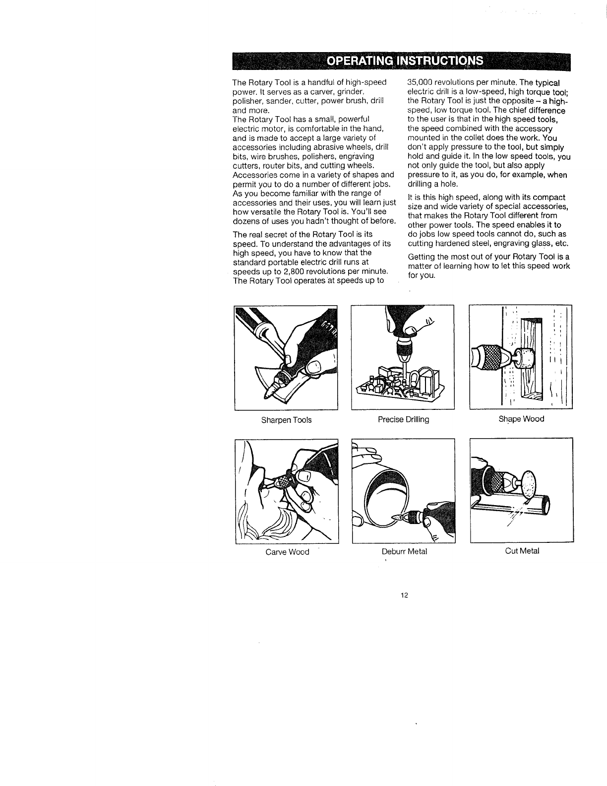
Sharpen Tools
Carve Wood
Precise Drilling Shape Wood
/
Deburr Metal Cut Metal
12
USING THE ROTARY POWER TOOL
The first step in learning to use the Rotary
Tool is to get the "feel" of it. Hold it in your
hand and feel its weight and balance. Feel
the taper of the housing. This taper permits
the Rotary Tool to be grasped much like a
pen or pencil. The Variable Speed tool has a
unique comfort grip on the nose and back
seating, which allows the user added
comfort and control during use. You can feel
the difference!
When you turn on the tool for the first time,
hold it away from your face. Accessories can
be damaged during handling, and can fly
apart as they come up to speed. This is not
common, but it may happen.
Practice on scrap materials first to see how
the Rotary Tool cuts. Keep in mind that the
work is done by the speed of the tool and by
the accessory in the collet. You should not
! lean on or push the tool into the work.
Instead, lower the spinning accessory lightly
to the work and allow it to touch the point at
which you want cutting (or sanding or
etching, etc.) to begin. Concentrate on
guiding the tool over the work using very
little pressure from your hand. Allow the
accessory to do the work.
Usually, it is best to make a series of passes
with the tool rather than attempt to do all the
work in one pass. To make a cut, for
example, pass the tool back and forth over
the work, much as you would a small paint
brush. Cut a little material on each pass until
you reach the desired depth. For most work,
the gentle touch is best. With it, you have
the best control, are tess likely to make
errors, and will get the most efficient work
out of the accessory.
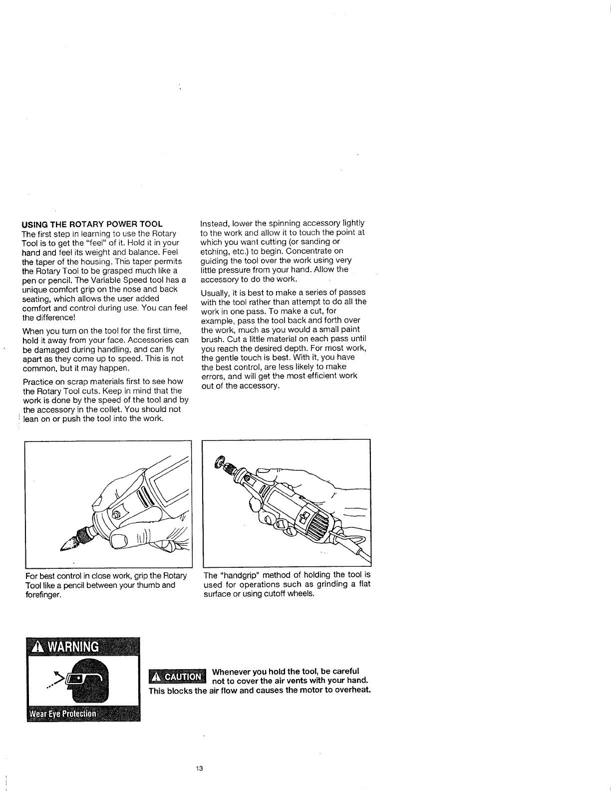
For best control in close work, grip the Rotary
Tool like a pencil between your thumb and
forefinger.
The "handgrip" method of holding the tool is
used for operations such as grinding a flat
surface or using cutoff wheels.
_henever you hold the tool, be careful
not to cover the air vents with your hand.
This blocks the air flow and causes the motor to overheat.
13
OPERATJN G SPEEDS
Set the speed indicator to fit the job; to achieve
the best job results when working with different
materials, the speed of the Rotary Tool shoukt
be regulated.
Models 610960 & 610950
Rotary Tools have an
integral speed control and an external
speed control should never be used with
these tools.
To select the right speed for each job, use a
practice piece of material. Vary' speed to find
the best speed for the accessory you are using
and the job to be done.
NOTE: Speed is affected by voltage
changes. A reduced incoming voltage will
slow the RPM of the tool, especially at the
lowest setting. If your tool appears to be
running slowly increase the speed setting
accordingly.
There are three basic types of Rotary Tools:
single speed, two-speed and variable speed
models.
•Single speed has one ON-OFF switch,
When the switch is on, the toot runs at
35,000 RPM.
• On the two-speed-model, there is a LO and
HI switch. When the switch indicator is on
the low setting, the tool runs at about 15,000
RPM. When the switch indicator is on the
high setting, the tool runs at about 35,000
RPM.
• On the variable speed model, there are
switch setting indicators marked with a
line. Slide to the number on the housing to
select the operating speed needed from
5,000 - 35,000 RPM.
You can refer to the charts on pages ?6 & 27'
to determine the proper speea, based on the
material being worked and the t_!_e o; t': _tb_ro:_
other accessory being used. These charts
enable you to select both the correct acces-
sory and the optimum speed at a glance.
If you have a single-speed or two-sF-ee'd
model, you will be able to use many
accessories to do a wide assortment of jobs.
For the majority of applications, all models of
the Rotary Tool should be used at top speed.
NEEDS FOR SLOWER SPEEDS
Certain materials, however, (some plastics, for
example) require a relatively slow speed
because at high speed the friction of the
accessory generates heat and causes the '
plastic to melt.
S_ow speeds (15,000 RPM or less) usually are
best for polishing operations employing the felt
polishing accessories. They may also be best
for working on delicate projects as "eggery"
work. delicate wood carving and fragile model
parts. All brushing applications require lower
speeds to avoid wire discharge from the
holder.
Higher speeds are better for carving, cutting,
routing, shaping, cutting dadoes or rabbets in
wood.
Hardwoods, metals and glass require high
speed operation, and drilling should also be
done at high speeds.
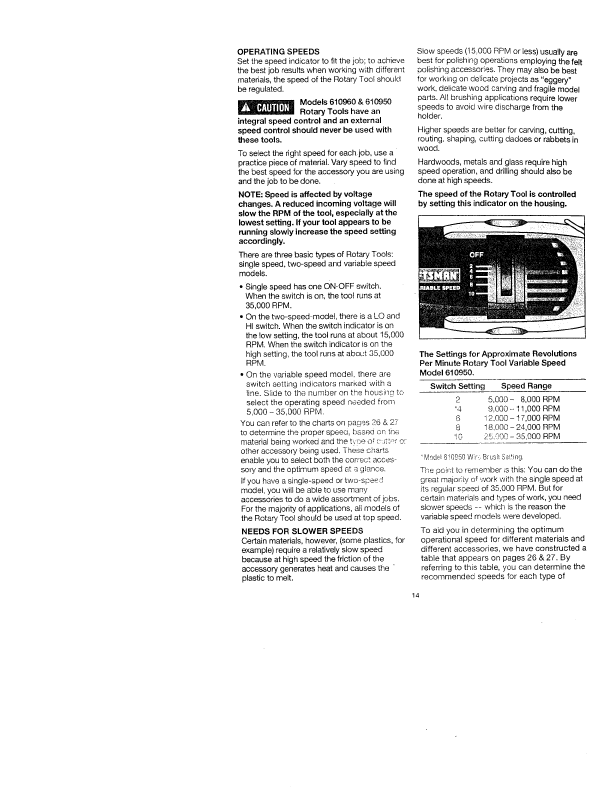
The speed of the Rotary Tool is controlled
by setting this indicator on the housing.
The Settings for Approximate Revolutions
Per Minute Rotary Tool Variable Speed
Model 610950.
Switch Setting Speed Range
2 5,000- 8,000 RPM
*4 9,000- 11,000 RPM
6 ! 2.000 - ! 7,000 RPM
8 18.000 - 24,000 RPM
I 0 25.000 - 35,900 RPM
"Model 610950Wir::Brusil Seiting.
The point to remem.ber is this: You can do the
great majority of work with the single speed at
its regular speed of 35.000 RPM. But for
certain materials and types of work, you need
slower speeds -- which is the reason the
variable speed models were developed.
To aid you in determining the optimum
operational speed for different materials and
different accessories, we have constructed
table that appears on pages 26 & 27. By
referring to this table, you can determine the
recommended speeds for each type of
14
accessory. Look this table over and become
familiar with it.
Ultimately, the best way to determine the
correct speed for work on any material is to
practice for a few minutes on a piece of
scrap, even after referring to the chart. You
can quickly learn that a slower or faster
speed is more effective just by observing
what happens as you make a pass or two at
different speeds. When working with plastic,
for example, start at a slow rate of speed
and increase the speed until you observe
that the plastic is melting at the point of
contact. Then reduce the speed slightly to
get the optimum working speed.
Some rules of thumb in regard to speed:
1. Plastic and materials that melt at low
i temperatures should be cut at low
;speeds.
2. Polishing, buffing and cleaning with a wire
brush must be done at speeds not greater
than 15,000 RPM to prevent damage to
the brush.
3. Wood should be cut at high speed.
4. Iron or steel should be cut at high speed if
using tungsten carbide accessory, but at
slower speeds if using high speed steel
cutters. If a high speed steel cutter starts
to chatter -- this normally means it is
running too slow.
5. Aluminum, copper alloys, lead alloys, zinc
alloys and tin may be cut at various
speeds, depending on the type of cutting
being done. Use paraffin or other suitable
lubricant on the cutter to prevent the cut
material from adhering to the cutter teeth.
Increasing the pressure on the tool is not the
answer when it is not cutting as you think it
should. Perhaps you should be using a
different cutter, and perhaps an adjustment
in speed would solve the problem. Leaning
on the tool does not help. The correct speed
will make using the rotary tool effortless.
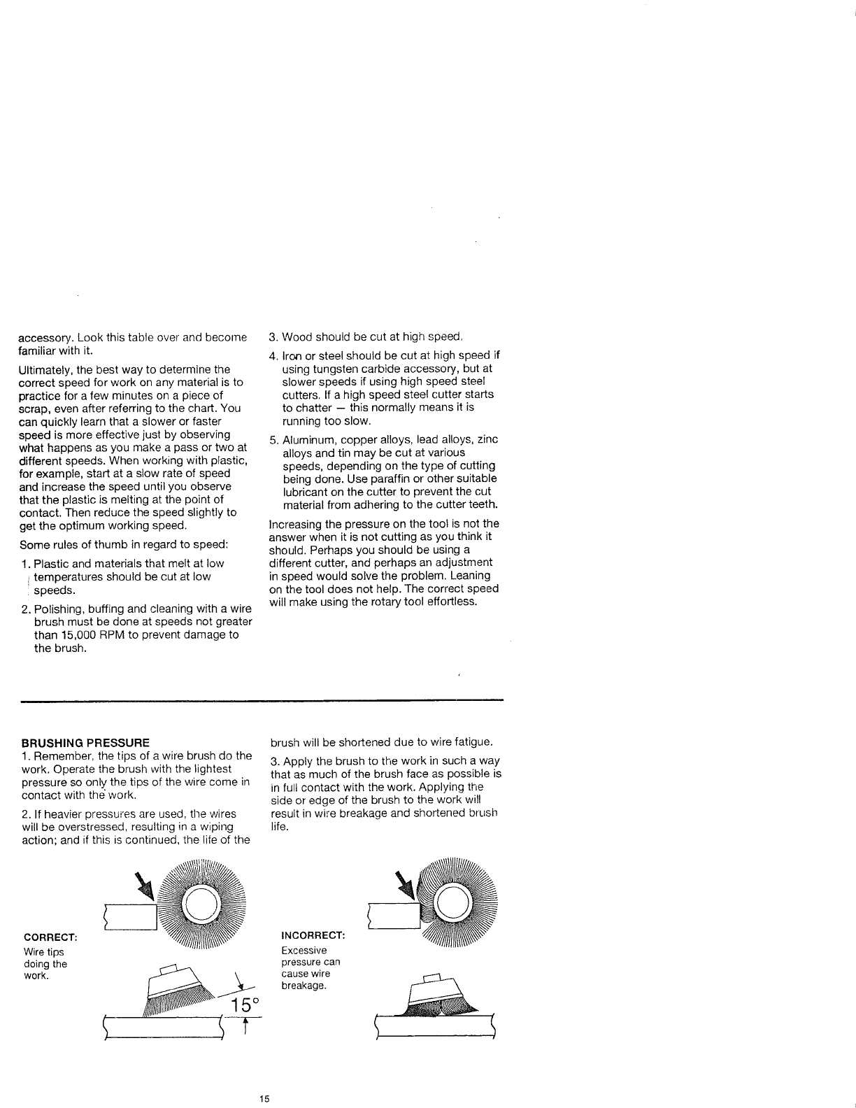
BRUSHING PRESSURE
1. Remember, the tips of a wire brush do the
work. Operate the brush with the lightest
pressure so only the tips of the wire come in
contact with the work.
2. If heavier pressures are used, the wires
will be overstressed, resulting in a wiping
action; and if this is continued, the life of the
brush will be shortened due to wire fatigue.
3. Apply the brush to the work in such a way
that as much of the brush face as possible is
in full contact with the work. Applying the
side or edge of the brush to the work wil!
result in wire breakage and shortened brush
life.
CORRECT:
Wire tips
doing the
work.
S
INCORRECT:
Excessive
pressure can
cause wire
breakage.
S
15
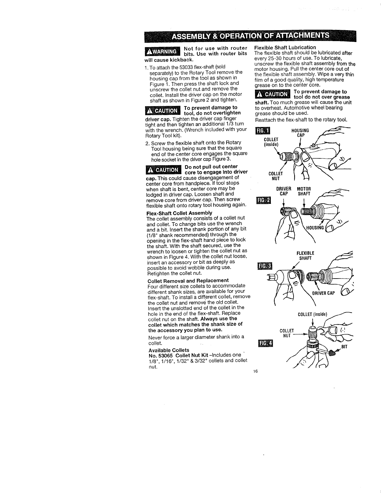
Not for use with router
bits. Use with router bits
will cause kickback.
1. To attach the 53033 flex-shaft (sold
separately) to the Rotary Tool remove the
housing cap from the tool as shown in
Figure 1. Then press the shaft lock and
unscrew the collet nut and remove the
collet. Install the driver cap on the motor
shaft as shown in Figure 2 and tighten.
To prevent damage to
tool, do not overtighten
driver cap. Tighten the driver cap finger
tight and then tighten an additional 1/3 turn
with the wrench. (Wrench included with your
Rotary Tool kit).
2. Screw the flexible shaft onto the Rotary
Tool housing being sure that the square
end of the center core engages the square
hole socket in the driver cap Figure 3.
Do not pull out center
core to engage into driver
cap. This could cause disengagement of
center core from handpiece. If tool stops
when shaft is bent, center core may be
lodged in driver cap. Loosen shaft and
remove core from driver cap. Then screw
flexible shaft onto rotary tool housing again.
Flex-Shaft Collet Assembly
The collet assembly consists of a co!let nut
and collet. To change bits use the wrench
and a bit. Insert the shank portion of any bit
(1/8" shank recommended) through the
opening in the flex-shaft hand piece to lock
the shaft. With the shaft secured, use the
wrench to loosen or tighten the collet nut as
shown in Figure 4. With the collet nut loose,
insert an accessory or bit as deeply as
possible to avoid wobble during use.
Retighten the collet nut.
Collet Removal and Replacement
Four different size collets to accommodate
different shank sizes, are available for your
flex-shaft. To install a different collet, remove
the collet nut and remove the old collet.
Insert the unslotted end of the collet in the
hole in the end of the flex-shaft. Replace
collet nut on the shaft. Always use the
collet which matches the shank size of
the accessory you plan to use,
Never force a larger diameter shank into a
collet.
Available Collets
No. 53065 Collet Nut Kit -Includes one
1/8", 1/16", 1/32" & 3/32" collets and collet
nut.
Flexible Shaft Lubrication
The flexible shaft should be lubricated after
every 25-30 hours of use. To lubricate,
unscrew the flexible shaft assembly from the
motor housing. Pull the center core out of
the flexible shaft assembly. Wipe a very thin
film of a good quality, high temperature
grease on to the center core.
To prevent damage to
tool do not over grease
shaft. Too much grease will cause the unit
to overheat. Automotive wheel bearing
grease should be used.
Reattach the flex-shaft to the rotary tool.
IHOUSING
CAP
COLLET / /
(insid__
DRIVER MOTOR
CAP SHAFT
FLEXIBLE
SHAFT
/
COLLET(inside)
COLLET (,I
NUT
_] 8IT
16
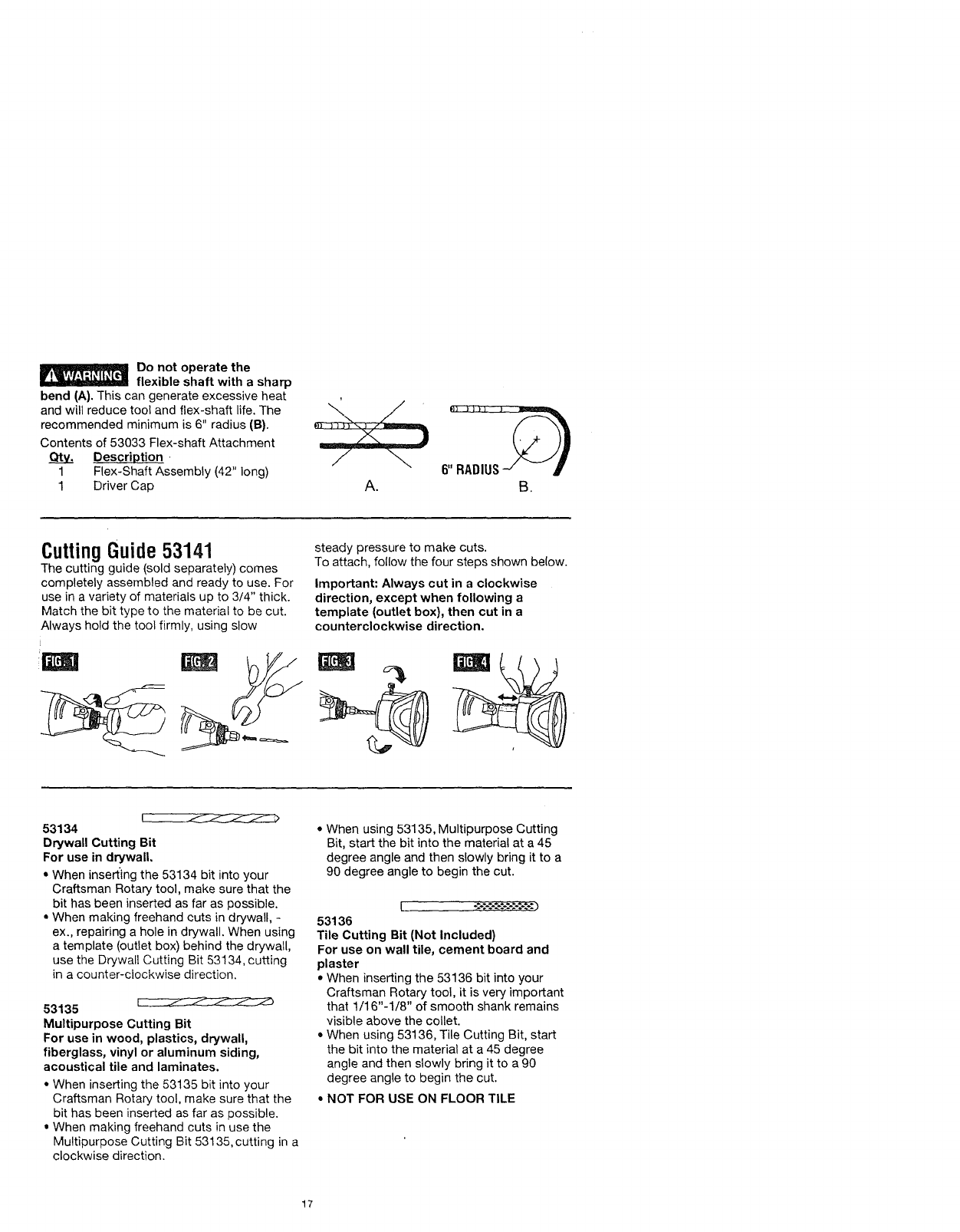
Do not operate the
flexible shaft with asharp
bend (A). This can generate excessive heat
and will reduce tool and flex-shaft life. The
recommended minimum is 6" radius (El).
Contents of 53033 Flex-shaft Attachment
Description
1 Flex-Shaft Assembly (42" long)
1 Driver Cap A. B.
CuttingGuide53141
The cutting guide (sold separately) comes
completely assembled and ready to use. For
use in a variety of materials up to 3/4" thick.
Match the bit type to the material to be cut.
Always hold the tool firmly, using slow
steady pressure to make cuts.
To attach, follow the four steps shown below.
Important: Always cut in a clockwise
direction, except when following a
template (outlet box), then cut in a
counterclockwise direction,
53134
Drywall Cutting Bit
For use in drywall.
• When inserting the 53134 bit into your
Craftsman Rotary tool, make sure that the
bit has been inserted as far as possible.
= When making freehand cuts in drywall, -
ex., repairing a hole in drywall. When using
a template (outlet box) behind the drywall,
use the Drywall Cutting Bit 53134, cutting
in a counter-clockwise direction.
53135
Multipurpose Cutting Bit
For use in wood, plastics, drywall,
fiberglass, vinyl or aluminum siding,
acoustical tile and laminates.
•When inserting the 53135 bit into your
Craftsman Rotary tool, make sure that the
bit has been inserted as far as possible.
• When making freehand cuts in use the
Multipurpose Cutting Bit 53135, cutting in a
clockwise direction.
•When using 53135, Multipurpose Cutting
Bit, start the bit into the material at a 45
degree angle and then slowly bring it to a
90 degree angle to begin the cut.
53136
Tile Cutting Bit (Not Included)
For use on wall tile, cement board and
plaster
•When inserting the 53136 bit into your
Craftsman Rotary tool, it is very important
that 1/16"-1/8" of smooth shank remains
visible above the cotlet.
• When using 53136, Tile Cutting Bit, start
the bit into the material at a 45 degree
angle and then slowly bring it to a 90
degree angle to begin the cut.
•NOT FOR USE ON FLOOR TILE
17
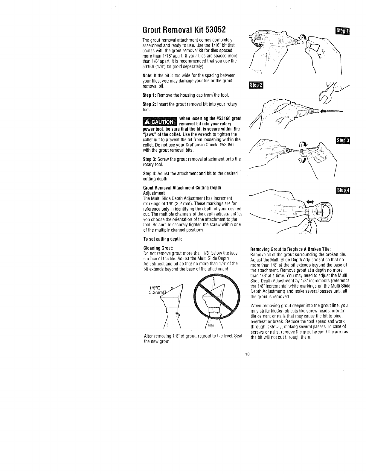
GroutRemoval Kit 53052
The grout removal attachment comes completely
assembled and ready to use. Use the 1/16" bit that
comes with the grout removal kit for tiles spaced
more than 1/16"apart. If yourtiles arespaced more
than 1/8"apart, it is recommended that you use the
53166 (1/8") bit (sold separately).
Note:If the bit is toowide for the spacing between
your tiles, you may damageyour tile or the grout
removal bit,
Step1: Removethe housing cap fromthe tool.
Step2: Insert the grout removal bit into your rotary
tool.
When insertingthe #53166 grout
removal bit into yourrotary
powertool, be sure thai the bit is securewithinthe
"jaws" of the collet. Usethewrench to tighten the
collet nut to preventthe bit from loosening within the
collet. Do not useyour Craftsman Chuck,#53050,
with the grout removal bits.
Step3: Screw thegrout removal attachment onto the
rotary tool.
Step 4: Adjust theattachment and bit to the desired
cutting depth.
GroutRemovalAttachmentCuttingDepth
Adjustment
TheMulti Slide Depth Adjustment has increment
markings of 1/8" (3,2 mm). These markings are for
referenceonly in identifying the depth of your desired
cut. The multiple channelsof the depth adjustment let
you choose the orientation of the attachment to the
tool. Be sure to securely tighten the screw within one
of the multiple channel positions.
To set cuttingdepth:
Cleaning Grout:
Do not removegrout more than 1/8" below the face
surface of the tile. Adjust the Multi Slide Depth
Adjustrnent and bit so that no more than 1/8" of the
bit extends beyond the base of the attachment.
1/8"[_
3,2ram
Alter removing 1'8" of grout, regrout to tile level.Seal
the new grout.
_=====-
_,_-_,_ i( _\
Removing Groutto Replace A Broken Tile:
Remove all of tile grout surrounding the broken tile.
Adjust the Multi Slide DepthAdjustment so that no
more than t/8" of the bit extends beyondthe base of
the attachment. Remove grout at a depth no more
than 1/8"at a time. You may needto adjust the Multi
Slide Depth Adjustment by 1/8" increments (reference
the 1/8"incremental white markings on the Multi Slide
Depth Adjustment) and makeseveral passes until all
the grout is removed.
When removing grout deeper into the grout line, you
may strike hidden objects like screw heads, mortar,
tile cement or nails that maycause tile bit to bind.
overheat or break. Reducethe tool speedand work
tllrough it slowly, making severalpasses. In case of
screws or nails, remove the grout around the areaas
the bit will not cut through them.
18
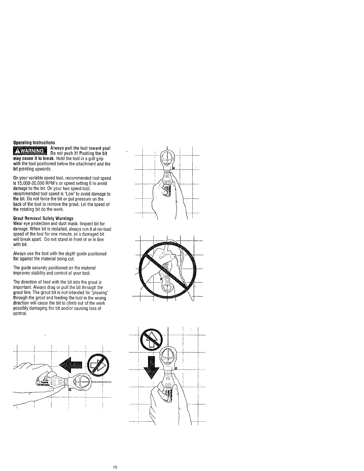
OperatingInstructions
_lways pull the tool towardyou!
Do netpushit] Pushingthe bit
may cause it to break. Holdthe toolin a golf grip
with the tool positioned below the attachment and the
bit pointing upwards.
Onyour variable speedtool, recommendedtool speed
is 15.000-20,000 RPM's or speed setting 6 to avoid
damageto the bit. Onyour two speedtool,
recommended tool speed is "Low"to avoid damageto
thebit. Do not force the bit or put pressure on the
back of the tool to remove the grout. Let the speed of
the rotating bit do the work.
GroutRemovalSafetyWarnings
Wear eyeprotection and dust mask. Inspect bit for
damage.When bit is installed, alwaysrun it at no-load
speed of the tool for one minute, asa damagedbit
witl break apart. Do not stand in front of or inline
with bit.
!
:Alwaysuse the tool with the depth guide positioned
flat against the material being cut.
Theguide securely positioned on the material
improves stability and control of your tool.
Thedirection of feedwith the bit into the grout is
important. Always drag or pull the bit through the
grout line. The grout bit is not intended for "plowing"
through the grout andfeeding the tool in the wrong
direction will causethe bit to climb out of the work
possibly damaging the bit and!or causing loss of
control.
iiI J
i
i
t'
19
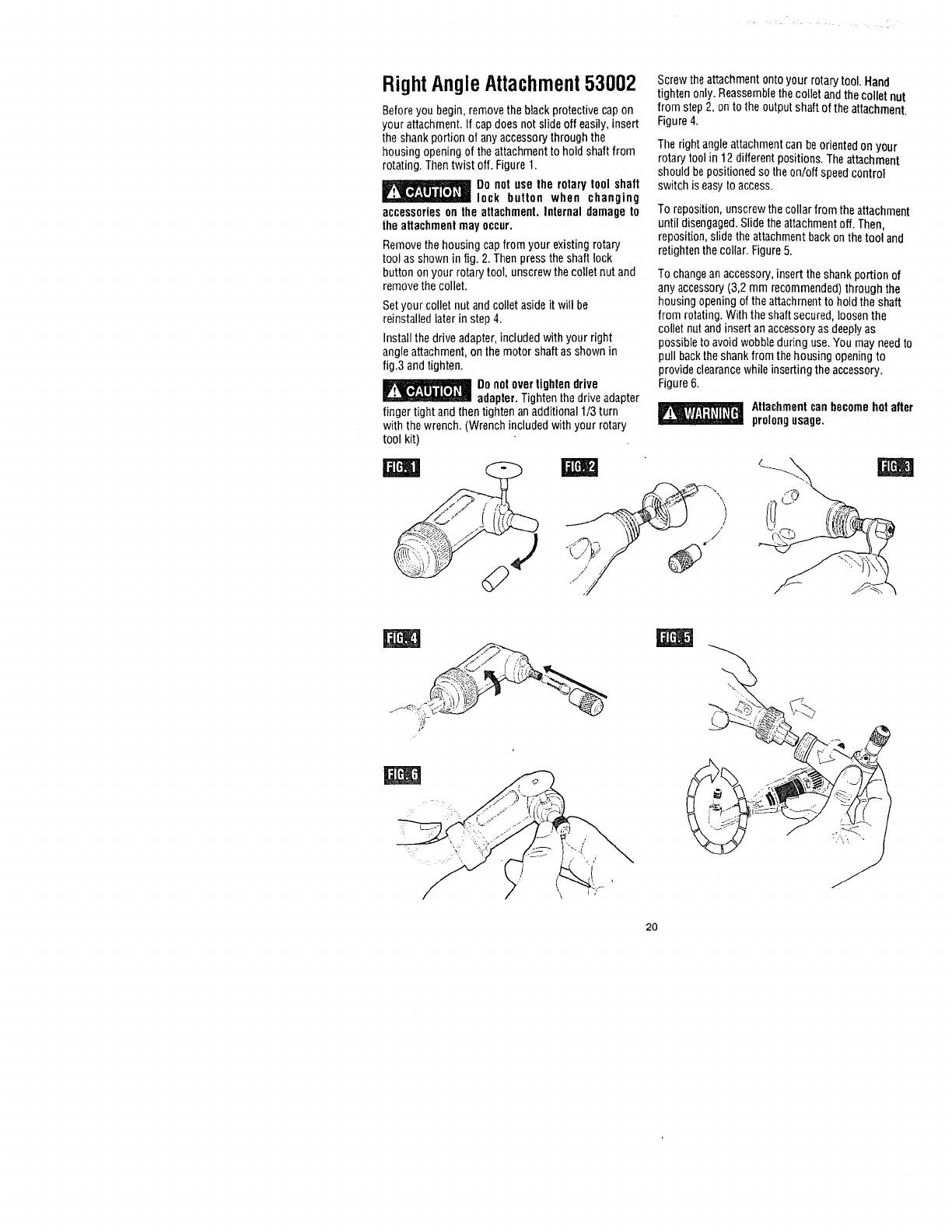
RightAngleAttachment53002
Before you begin, removethe black protective capon
your attachment. If cap doesnot slide off easily, insert
the shank portion of anyaccessory through the
housing opening of the attachmentto hold shaft from
rotating. Then twist off. Figure 1.
Do not use the rotary !ool shaft
lock button when changing
accessorieson the attachment. Internal damage to
the attachmentmayoccur.
Removethe housing capfrom your existing rotary
tool as shown in Jig. 2. Thenpressthe shaft _ock
button on your rotary tool, unscrew the collet nut and
removethe collet.
Setyour collet nut and collet asideit will be
reinstalled later in step 4.
Install the drive adapter,included with your right
angle attachment,on the motor shaft asshown in
fig.3 and tighten.
Donot over tightendrive
adapter. Tighten the driveadapter
finger tight and then tighten an additional 1/3 turn
with the wrench. (Wrench included with your rotary
tool kit)
/
Screw the attachment onto your rotary tool. Hand
tighten only. Reassemblethe collet and the collet nut
from step2, on to the output shaft of the attachment.
Figure4.
Theright angle attachmentcan be orientedon your
rotary tool in 12 different positions. Theattachment
should be positioned so the on/off speed control
switch is easy to access.
To reposition, unscrewthe collar from the attachment
until disengaged.Slidethe attachmentoff. Then,
reposition,slide the attachment back on the tool and
retightenthe collar. Figure5.
To changean accessory,insert the shank portion of
anyaccessory(3,2 mm recommended) through the
housing openingof the attachmentto hold the shaft
from rotating. With the shaft secured, loosen the
collet nut andinsert an accessoryas deeplyas
possibleto avoid wobbleduring use.You may needt(
pull backthe shank from the housing opening to
provide clearancewhile inserting the accessory.
Figure 6.
_Attachmentcanbecomehot afte
prolongusage.
2O
r-- _ , 3 3,
_Drvice
Preventive maintenance pe-
rformed by unauthorized
personnel may result in misplacing of
Internal wires and components which could
cause serious hazard, We recommend that all
tool service be performed by a Sears Service
Center.
CARBON BRUSHES
The brushes and commutator in your tool have
been engineered for many hours of dependable
service. To maintain peak efficiency of the
motor, we recommend every 50-60 hours the
brushes be examined. Only genuine Craftsman
replacement brushes specially designed for
your tool should be used.
iMAINTENANCE OF
iREPLACEABLE BRUSHES
Models 610830, 610960 & 610950,
The brushes should be inspected frequently
when tools are used continuously. If your tool
runs sporadically, loses power, makes unusual
noises or runs at a reduced speed, check the
brushes. TO continue using the tool in this
condition will permanently damage your tool.
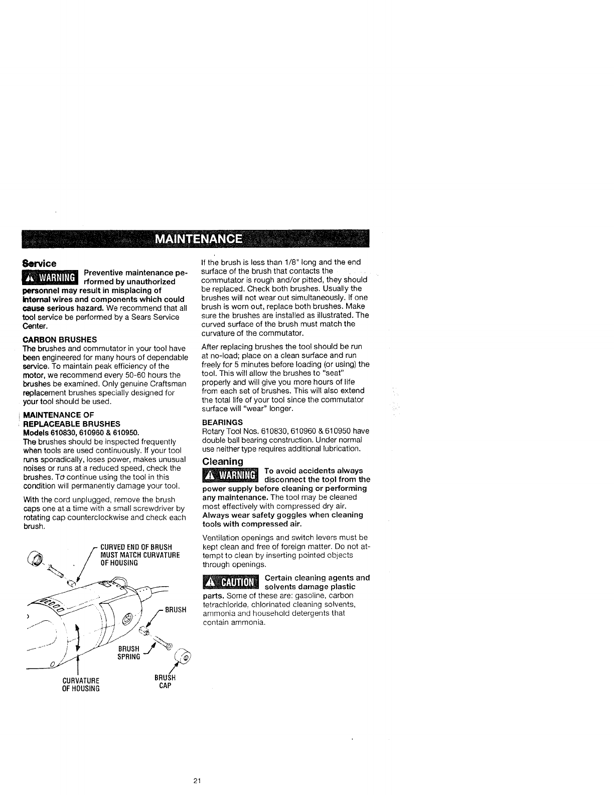
With the cord unplugged, remove the brush
caps one at a time with a small screwdriver by
rotating cap counterclockwise and check each
brush.
CURVEDENDOFBRUSH
q_ MUSTMATCHCURVATURE
OFHOUStNG
%,%--#
/
CURVATURE
OFHOUSING
BRUSH
SPRING
BRUSH
j%
BRUSH
CAP
If the brush is less than 1/8" long and the end
surface of the brush that contacts the
commutator is rough and/or pitted, they should
be replaced. Check both brushes. Usually the
brushes will not wear out simultaneously. If one
brush is worn out, replace both brushes. Make
sure the brushes are installed as illustrated. The
curved surface of the brush must match the
curvature of the commutator.
After replacing brushes the tool should be run
at no-load; place on a clean surface and run
freely for 5 minutes before loading (or using) the
tool. This witl allow the brushes to "seat"
properly and will give you more hours of life
from each set of brushes. This will also extend
the total life of your tool since the commutator
surface will "wear" longer.
BEARINGS
Rotary Tool Nos. 610830, 610960 & 610950 have
double ball bearing construction. Under normal
use neither type requires additional lubrication.
Cleaning
To avoid accidents always
disconnect the tool from the
power supply before cleaning or performing
any maintenance. The tool may be cleaned
most effectively with compressed dry air.
Always wear safety goggles when cleaning
tools with compressed air.
Ventilation openings and switch levers must be
kept clean and free of foreign matter. Do not at-
tempt to clean by inserting pointed objects
through openings.
Certain cleaning agents and
solvents damage plastic
parts. Some of these are: gasoline, carbon
tetrachloride, chlorinated cleaning solvents,
ammonia and household detergents that
contain ammonia.
21

Extension Cords
lf an extension cord is necessary, a cord with adequate size
conductors that is capable of carrying the current necessary for your
tool must be used. This will prevent excessive voltage drop, loss of power or overheating.
Grounded tools must use 3-wire extension cords that have 3-prong plugs and receptacles.
RECOMMENDED SIZES OF EXTENSION CORDS
120 VOLT ALTERNATING CURRENT TOOLS
Tool's
Ampere
Rating
3-6
6-8
8-10
10-12
12-16
Cord Size inA.W.G.
Cord Lengthin Feet
25 50 100 150
18 16 16 14
18 16 14 12
18 16 14 12
16 16 14 12
14 12
Wire Sizesin mm2
Cord Lengthin Meters
15 30 60 120
.75 .75 1.5 2.5
.75 1.0 2.5 4.0
.75 1.0 2.5 4.0
1.0 2.5 4.0 --
NOTE: The smaller the gauge number, the heavier the cord.
22
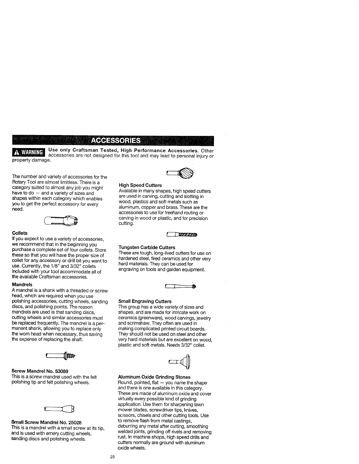
Use only Craftsman Tested, High Performance Accessories, Other
accessories are not designed for this tool and may lead to personal injury or
property damage.
The number and variety of accessories for the
Rotary Tool are almost limitless. There is a
category suited to almost any job you might
have to do -- and a variety of sizes and
shapes within each category which enables
you to get the perfect accessory for every
need.
toilets
If you expect to use a variety of accessories,
we recommend that in the beginning you
purchase a complete set of four collets. Store
these so that you will have the proper size of
collet for any accessory or drill bit you want to
use. Currently, the 1/8" and 3/32" collets
included with your tool accommodate all of
the available Craftsman accessories.
Mandrels
A mandrel is a shank with a threaded or screw
head, which are required when you use
polishing accessories, cutting wheels, sanding
discs, and polishing points. The reason
mandrels are used is that sanding discs,
cutting wheels and similar accessories must
be replaced frequently. The mandrel is a per-
manent shank, allowing you to replace only
the worn head when necessary, thus saving
the expense of replacing the shaft.
Screw Mandrel No. 53089
This is a screw mandrel used with the felt
polishing tip and felt polishing wheels.
Small Screw Mandrel No. 25028
This is a mandrel with a small screw at its tip,
and is used with emery cutting wheels,
sanding discs and polishing wheels.
High Speed Cutters
Available in many shapes, high speed cutters
are used in carving, cutting and slotting in
wood, plastics and soft metals such as
aluminum, copper and brass. These are the
accessories to use for freehand routing or
carving in wood or plastic, and for precision
cutting.
Tungsten Carbide Cutters
These are tough, long-lived cutters for use on
hardened steel, fired ceramics and other very
hard materials. They can be used for
engraving on tools and garden equipment.
Small Engraving Cutters
This group has a wide variety of sizes and
shapes, and are made for intricate work on
ceramics (greenware), wood carvings, jewelry
and scrimshaw. They often are used in
making complicated printed circuit boards.
They should not be used on steel and other
very hard materials but are excellent on wood,
plastic and soft metals. Needs 3/32" collet.
Aluminum Oxide Grinding Stones
Round, pointed, flat -- you name the shape
and there is one available in this category.
These are made of aluminum oxide and cover
virtually every possible kind of grinding
application. Use them for sharpening lawn
mower blades, screwdriver tips, knives,
scissors, chisels and other cutting tools. Use
to remove flash from metal castings,
deburring any metal after cutting, smoothing
welded joints, grinding off rivets and removing
rust. In machine shops, high speed drills and
cutters normally are ground with aluminum
oxide wheels.
23
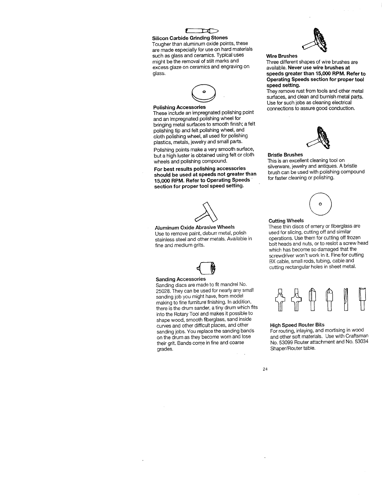
Silicon Carbide Grinding Stones
Tougher than aluminum oxide points, these
are made especially for use on hard materials
such as glass and ceramics. Typical uses
might be the removal of stilt marks and
excess glaze on ceramics and engraving on
glass.
O
Polishing Accessories
These include an impregnated polishing point
and an impregnated polishing wheel for
bringing metal surfaces to smooth finish; a felt
polishing tip and felt polishing wheel, and
cloth polishing wheel, all used for polishing
plastics, metals, jewelry and small parts.
Polishing points make a very smooth surface,
but a high luster is obtained using felt or cloth
wheels and polishing compound.
For best results polishing accessories
should be used at speeds not greater than
15,000 RPM. Refer to Operating Speeds
section for proper tool speed setting.
Aluminum Oxide Abrasive Wheels
Use to remove paint, deburr metal, polish
stainless steel and other metals. Available in
fine and medium grits.
43
Sanding Accessories
Sanding discs are made to fit mandrel No.
25028. They can be used for nearly any small
sanding job you might have, from model
making to fine furnitur_ finishing. In addition,
there is the drum sander, a tiny drum which fits
into the Rotary Tool and makes it possible to
shape wood, smooth fiberglass, sand inside
curves and other difficult places, and other
sanding jobs. You replace the sanding bands
on the drum as they become worn and lose
their grit. Bands come in fine and coarse
grades.
Wire Brushes
Three different shapes of wire brushes are
available. Never use wire brushes at
speeds greater than 15,000 RPM. Refer to
Operating Speeds section for proper tool
speed setting.
They remove rust from tools and other metal
surfaces, and clean and burnish metal parts.
Use for such jobs as cleaning electrical
connections to assure good conduction.
Bristle Brushes
This is an excellent cleaning tool on
silverware, jewelry and antiques. A bristle
brush can be used with polishing compound
for faster cleaning or polishing.
O
Cutting Wheels
These thin discs of emery or fiberglass are
used for slicing, cutting off and similar
operations. Use them for cutting off frozen
bolt heads and nuts, or to reslot a screw head
which has become so damaged that the
screwdriver won't work in it. Fine for cutting
BX cable, small rods, tubing, cable and
cutting rectangular holes in sheet metal.
High Speed Router Bits
For routing, inlaying, and mortising in wood
and other soft materials. Use with Craftsman
No. 53099 Router attachment and No. 53034
Shaper/Router table.
24
1
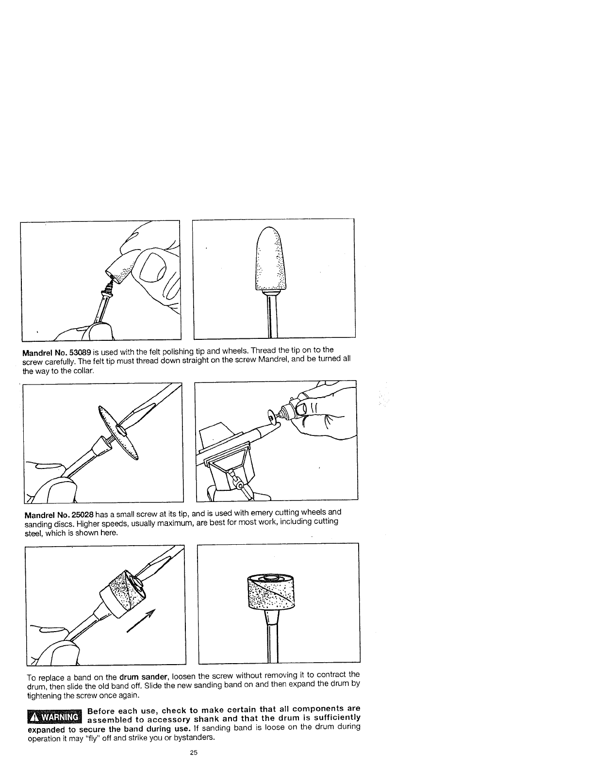
Mandrel No. 53089 is used with the felt polishing tip and wheels. Thread the tip on to the
screw carefully. The felt tip must thread down straight on the screw Mandrel, and be turned all
the way to the collar.
If
Mandrel No. 25028 has a small screw at its tip, and is used with emery cutting wheels and
sanding discs. Higher speeds, usually maximum, are best for most work, including cutting
steel, which is shown here.
To replace a band on the drum sander, loosen the screw without removing it to contract the
drum, then slide the old band off. Slide the new sanding band on and then expand the drum by
tightening the screw once again.
Before each use, check to make certain that all components are
assembled to accessory shank and that the drum is sufficiently
expanded to secure the band during use. If sanding band is loose on the drum during
operation it may "fly" off and strike you or bystanders.
25
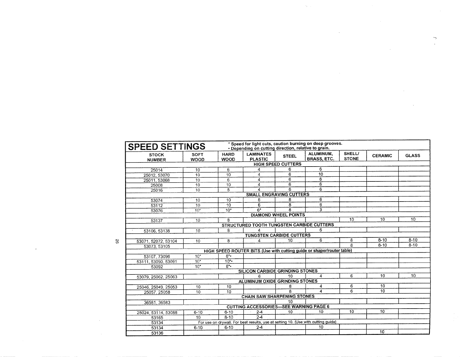
SPEED SETTINGS
STOCK I SOFT
NUMBER WOOD
25014 _ 10
25012,53070 10
25011,53068 10
25008 10
25016 10
53074
53112
53076
53137 [
53106, 53138
53071,52072,53104 [
53073,53105
I
53107,73096
53111, 53090,53091
53092
53079,25062,25063 1
25046,25049,25053
25057,25058
36581,36583 l
25024,53114,53088
53165
53134
53134
53136
10
10
10*
10
10
10
10'
10"
10"
10
10
6-10
10
For use on drywall For best results, use at settincj 10. (Use with cuttin 9 guide)
* Speed for light cuts, caution burning on deep grooves.
•Depending on cuttin 9direction relative to grain. ISHELL/
WOOD PLASTIC STEEL [BRASS_ ETC. [
IHARD LAMINATES , [ALUMINUM, STONE
HIGH SPEED CUTTERS
6 4 6 I6
10 4 6 I 10
6 4 6 6
10 4 6 6
8 4 6 6
SMALL ENGRAVING CUTTERS
10 6 8 6
10" 6* 8 3
DIAMOND WHEEL POINTS
1 8 I I I I lO
STRUCTURED TOOTH TUNGSTEN CARBIDE CUTTERS
I 8 I 4 I I 6 I
TUNGSTEN CARBIDE CUTTERS
SILICON CARBIDE GRINDING STONES
I I 6 I 10 I 4 I 6
ALUMINUM OXIDE GRINDING STONES
I I I4 °
10 8 4 6
CHAINSAWSHARPENINGSTONES
I I I 10 I I
CUTTING ACCESSORIES--SEE WARNING PAGE 6
ICERAMIC t GLASS
I 10 I10
I I
18-10 I 8-10
8-10 8-10
I
I lO I lO
I lO1o I
I I
I ,o I
I,o I I

SPEED SETTINGS
STOCK ISOFT
NUMBER WOOD
53082
25033
53110
53120
25038_25039,53087
53131
53116,53117,53118 I
25042,53083,25043
53084
53136,53162 I
53164
53166 ]
I
4 4
4
6 6 6
4 4 4
2-10 2-10 I 10
2-10 2-10 I 10
8 8 2-4
10 I 8 I 8-10
6I6 l 6
For Use on Wal and Floor Grout {Use w th grout removal cuttin# €luide)
* Speed for light cuts, caution burning on deep grooves.
• Depending on cutting direction relative to grain.
HARD LAMINATES I ..... I ALUMINUM,
WOOD PLASTIC b/I-I=L {BRASS_ ET €. ]
POLISHING ACCESSORIES
6 6
6-8 6-8
2-4 6 6
4
2 6
4
SANDING BANDS AND DISCS
.p,op
2-6 10
2-4
FLAPWHEELS
2 I lO I I
FINISHING ABRASIVE BUFFS
4 l 6 I I
GROUT REMOVAL BITS I
SHELL/
STONE
6
6-8
4
2-10
2-10
ICERAMIC IGLASS
6 6
6-8 6-8
2-10
2-10
I
[
I
!
1
,, [, ,6-8
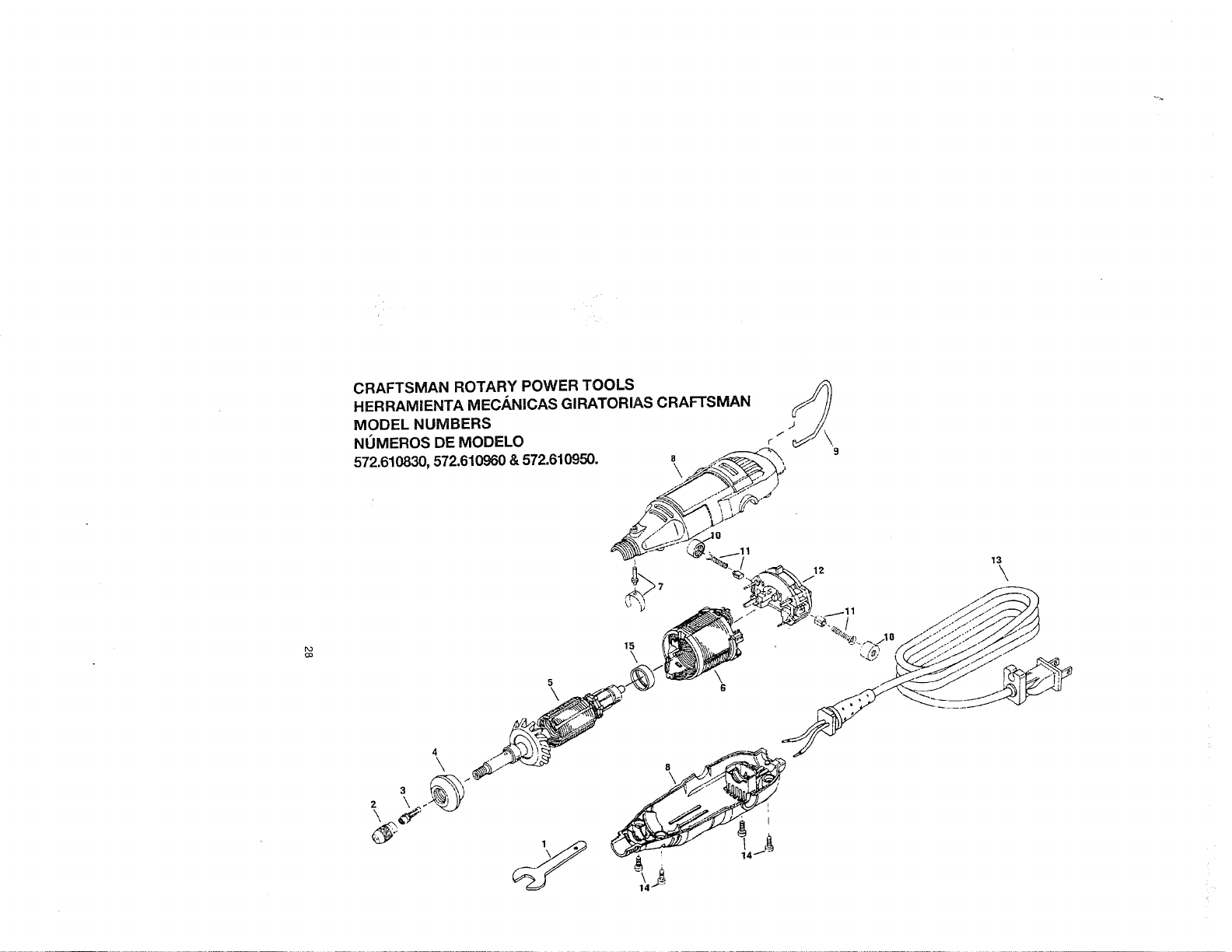
CRAFTSMANROTARY POWER TOOLS
HERRAMIENTA MEC.,_NICAS GIRATORIAS CRAFTSMAN
MODEL NUMBERS
NOMEROS DE MODELO
572.610830,572.610960 & 572.610950.
7
5\
15
\
\G
3
4\
I
12
13\

CODE NO.
NUMERO DE CODIGO
1
2
3
4
5
6
7
8
9
10
11
12
13
14
15
CODE NO.
NUMERO DE CODIGO
3
8
12
PART NO.
NUMERO DE PIEZA
2615990962
2615297355
"481
2615294028
2610912779
2610907324
2615297356
o
2615294043
2615302217
2615302695
2615294041
2615294O35
2615297373
MODEL
MODELO,
572.61083_
480
2615297374
2610912839
2610912840
2610912838
MODEL ,
MODELO
572.610960
48O
2615297374
2610912844
2610912845
2610912843
DESCRIPTION
Wrench
Collet Nut
1/8" Collet (In Tool)
3/32" Collet
Housing Cap
Armature & Bearing Assembly
Field Assembly
Collet Lock & Spring
Housing Set
Hanger
Brush Cap (Pair)
Brush Spring (Pair)
Switch Assembly
Cord
Screws (Individual)
Isolator
DESCRIPCION
Llave de tuerca
Tuerca del portaherramienta
Portaherramienta de 3,2 mm (en la herramienta)
Portaherramienta de 2,4 mm
Tapa de la caja protectora
Ensamblaje de inducido y rodamientos
Ensamblaje de campo
Cierre y resorte de portaherramienta
Juego de caja protectora
Gancho
Tapa para escobillas (par)
Muelle para escobillas (par)
Ensamblaje det interruptor
Cord6n
Tornilto
Aislante
MODEL
MODEL0
572.610950'
480
2610912816
2610912832
2610912833
2610912831
DESCRIPTION
1/8" Collet (In Tool)
Housing Set
Switch Assembly
DESCRIPCION
Portaherramienta de 3,2 mm
(en la herramienta)
Juego de caja protectora
Ensamblaje del interruptor
1
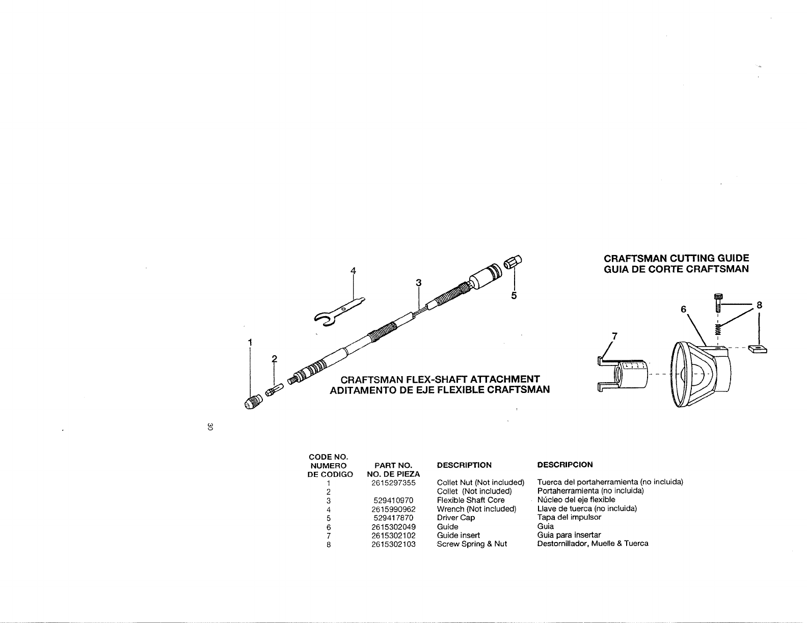
CRAFTSMAN FLEX-SHAFT A'I-rACHMENT
ADITAMENTO DE EJE FLEXIBLE CRAFTSMAN
CRAFTSMAN CUTTING GUIDE
GUIA DE CORTE CRAFTSMAN
7I
CODE NO.
NUMERO PART NO, DESCRIPTION
DE CODIGO NO. DE PIEZA
1 2615297355 Collet Nut (Not included)
2 Collet (Not included)
3 529410970 Flexible Shaft Core
4 2615990962 Wrench (Not included)
5 529417870 Driver Cap
6 2615302049 Guide
7 2615302102 Guide insert
8 2615302103 Screw Spring & Nut
DESCRIPCION
Tuerca del portaherramienta (no incluida)
Portaherramienta (no incluida)
NL_cleodel eje flexible
Llave de tuerca (no incluida)
Tapa del impulsor
Guia
Guia para insertar
DestornUlador, Muelle & Tuerca
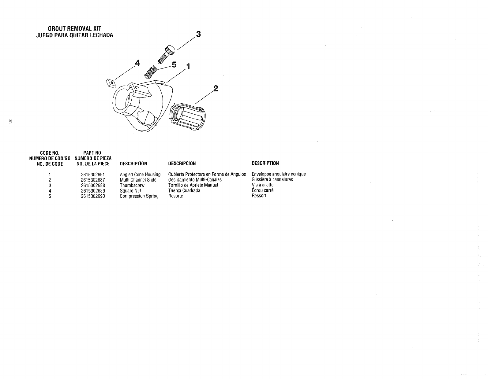
GROUTREMOVALKIT
JUEGOPARAQUITARLECHAOA
CODENO. PARTNO.
NUMERODECODIGO NUMERODEPIEZA
NO. DECODE NO. DE LAPIECE DESCRIPTION DESCRIPCION
1 2615302691 Angled Cone Housing
2 2615302687 Multi ChannelSlide
3 2615302688 Thumbscrew
4 2615302689 Square Nut
5 2615302690 CompressionSpring
Oubierta Protectoraen Formade Angulos
DeslizamientoMulti-Canales
Torni!lo de AprieteManual
Tuerca Cuadrada
Resorte
DESCRIPTION
Enveloppeangulaire conique
Glissi_re_ cannelures
Vis _ ailette
I_croucarr6
Ressort
Indice Pdgina
Garantfa.................................................................... 32
Normas de seguridad para herramientas rne_nicas ............................... 33-36
Sfmbolos ................................................................... 37
Descripci6n funcional y especificaciones........................................ 38-39
Ensamblaje............................................................... 40-41
Instrucciones de funcionamiento .............................................. 42-45
Velocidadesde funcionamientopara los accesorios ............................... 46-50
Mantenimiento ............................................................ 51-52
Accesorios ............................................................... 53-57
Piezasde repuesto......................................................... 28-31
GarantiadeSears
Garantfacompletade unafiopara la herramientamec_nicasgiratoriasCraftsman
Si no est,. completamente satisfecho con esta herramientamec_nicasgiratorias Craftsman
dentro del plazo de un afio a partir de la fecha de compra, Searsla reemplazar_,gratuitamente.
Siesta herramientamec_nicasgiratorias se utiliza con fines comerciales o de alquiler, esta
garantia solamentetiene una afio de aplicaci6n a partir de la fecha de compra.
Serviciode garantfa
El servicio de garantla se encuentradisponible devolviendo esta herramientamec_nicasgiratorias
Craftsman a la tiendaSears m_s pr6xima en los EstadosUnidos.
Esta garantfatiene aplicaci6n solamente mientras estaherramientamec__nicasgiratoriasse utilice
en los EstadosUnidos.
Esta garant[a le confiere a usted derechos legales espec[ficos yes posible que tambien tenga
otros derechos que varian de un estado a otro.
Sears, Roebuckand Co., Dept.817WA, HoffmanEstates, IL 60179
32
Leay entiendatodaslas instrucciones.Elincumplimientode todaslasinstrucciones
indicadasa continuaci6npuededar lugar a sacudidasel_ctricas,incendlosy/o lesiones
personalesgraves. CONSERVEESTASINSTRUCCIONES
Area de trabajo
Mantengael _rea de trabajo limpia y bien
Iluminada. Las mesasdesordenadasy las_reas
oscurasinvitanaquese produzcan accidentes.
Noutilice herramientasmec_nicas enatm6sferas
explosivas,tales cometasexistentesenpresencia
deliquidos, gases o polvosinliamables.Las
herrarnientasmec_nicasgeneran chispas y 6stas
puedendar lugar a la ignici6n del polvo o los vapores.
Mantengaa las personasque se encuenlren
presentes, a los nifiosy a losvisitantesalejadosal
utilizar una herramientamec_nica. Las
distracciones pueden hacer que ustedpierda el
control.
33
Seguridadel_ctrica
Las herramientasconaislamiento dobleesl=in
equipadasconun enchufepolarizado (unterminal
es m_s anchoque el otro). Esteenchufeentrar_ en
untomacorrientepolarizadosolamentede una
manera. Si el enchuleno entra porcompleloen el
tomacorriente, d_le la vuelta. Si siguesin entrar,
p6ngaseencontactoconun electricistacompetente
para instalarun tomacorrientepolarizado. Nohaga
ning_int,q.fipode cambioen e] enchufe.Elaislamiento
doble IDI elimina la necesidad delsistema de cord6n
de energiade tres hilos conectadoa tierra y lafuente
de energfaconectadaa tierra. Antesde enchufarla
herramienta, aseg0resede que la tensi6n del
tomacorriente suministrada se encuentre dentro del
margen de la tensi6n especificadaen la placadel
fabricante. No utilice herramientas con capacidad
nominal "ACsolamente° ("AConly") con unafuente de
energia DC.
Evite el contactodel cuerpoconlas superficies
conectadasa tierra tales comotuberfas,
radiadores, estufasde cocinay refrigeradores.Hay
mayor riesgo de que se produzcan sacudidas
el_ctricassi su cuerpo est_conectadoa tierra. Si la
utilizaci6n de la herramientamec_nicaen lugares
h_medos es inevitable, sedebe usar un interruptor de
oircuitopara fallos a tierra para suministrar la energfa
a la herramienta. Los guantes de goma para
electrieista y el calzadoantideslizante aumentar_n
m_s la seguridad personal.
No expongalas herramientasmec_nicas a la Iluvia
ni asituacionesb0medas.La entrada de aguaen una
herramienta mecanica aumentar_el riesgo de que se
produzcan sacudidas electricas.
No abuse del cord6n. Nuncauseel cordon para Ilevar
las herramientas ni para sacarel enchufe de un
tomacorriente.Mantenga el cord6n alejadodel calor,
el aceite, los bordes afilados o las piezasm6viles.
Gamblelos cordones da5adosinmediatamente. Los
cordones dafiadosaumentan el riesgo de que se
produzcan sacudidasel6ctricas.
AI utilizar unaherramienla mec_nicaa la
intemperie, utilice un cord6ndeextensi6npara
intemperiemarcado"W-A"o "W". Estos cordones
tienen capacidadnominal para uso a la intemperiey
reducen el riesgode que se produzcansacudidas
el6ctricas. Consulte'3ama5os recomendadosde los
cordones de extensi6n_en la secci6n Accesoriosde
este manual.
Seguridadpersonal
Mant_ngasealerta, fijese en Io que est:_haciendo y
useel sentidocomzincuandoutilice una
herramienta mec_nica. Nouse la herramienta
cuandoest6 cansadoo se encuentrebajola
influencia dedrogas,alcoholomedicamentos.Un
momento de distracci6n al utilizar herramientas
mec_nicaspuede darlugar a lesiones personales
graves.
Vistaseadecuadamente.Nose pongaropaholgada
ni joyas. Suj_tese el pelo. Mantengael pelo, la
ropay los guantesalejados de las piezasm6viles.
La ropa holgada, lasjoyas o el pelo largo pueden
quedar atrapadosen las piezasm6viles. Mantenga los
mangos secos, limpios y libresde aceitey grasa.
Eviteel arranqueaccidental.Asegdresede que el
interruptorest6 enla posici6n"OFF"(apaoado)
antesde enchularla herramienta.El Ilevar las
herramientascon el dedo en el interruptoro el
enchufarherramientasque tenganel interruptoren la
posici6n "ON"(encendido) invita a que seproduzcan
aceidentes.
Quite las Ilaves deajuste o detuerca antesde
encenderla herramienta.Una Ilave deajuste o de
tuerca que sedeje puesta en una piezagiratoria de la
herramientapuede ocasionarlesiones personales.
No intente alcanzardemasiadolejos. Mantenga un
apoyodelos piesyun equilibrioadecuadosen todo
momento.El apoyo de los pies y el equilibrio
adecuadospermiten un mejor control de la
herramientaen situaciones inesperadas.
Utiliee eqoipode seguridad, Use siempre
prolecci6n de los ojos. Se debe utilizar una m_,scara
antipolvo, zapatos de seguridad antideslizantes,casco
o proteccion de los oidos seg0n Io requieran las
condiciones.
Utilizaci6n y cuidado de las herramientas
Utiliceabrazaderasuotro modo pr_ctico de fijar y
soportarla piezade trabajoa unaplataforma
estable. La sujeci6n de la piezade trabajo con la
manoo contra et cuerpo resulta inestable y puede
ocasionarp6rdida de control.
No fuerce la herramienta. Use la herramienta
correctapara la aplicaci6n que d_sea. La
herramienta correcta har_ el trabajomejory con rnas
seguridad a la capacidadnominal parala que est_
dise_ada.
No utilice la herramientasi el interrupterno la
enciende oapaga, Toda herramientaque no se
pueda controlar con el interrupter espeligrosay debe
ser reparada.
Desconecteel enchufede la fuente deenergia
antes de hater cualquierajuste,cambiar
accesorioso guardarla herramienta.Estasmedidas
de seguridad preventivas reducene! riesgo de
arrancar la herramienta accidentalmente.
Guarde las herramientasque no est6usandofuera
del alcance de los niflosy otraspersonasno
capacitadas. Las herramientasson peligrosas en las
manes de los usuarios no capacitados.
Mantenga las herramientasconcuidado.Conserve
las herramientasde cortealiladasy limpias. Las
herramientas mantenidasadecuadamente,con hordes
de corte afilados, tienen menosprobabilidadesde
atascarse y son m&s f_.cilesde controlar.Toda
alteraci6n o modificaci6n constituye un use
incorrecto y puedetenor come resultadouna
situaci6n peligrosa.
Compruebela desalineaci6no el atascodelas
piezasm6viles, la rupturade piezasy cualquier
otrasituaci6nque puedaalectar el funcionamiento"
de las herramientas. Si la herramientaest_
dafiada, hagaque realicen unserviciode ajustesy
reparacionesa la herramientaantes deusarla.
Muchos accidentesson causadosper herramientas
mantenidasdeficientemente.Establezcaun programa
de mantenimientoperi6dico para la herramienta.
Utilice _nicamente accesoriosque est_n
recomendadosper el fabricantede su modelo. Los
accesorios quepueden ser adecuadospara una
herrarnientapueden volverse peligrosos cuando se
utilizanen otra herramienta.
Servicio
Elserviciodeajustesy reparacionesde una
herramientadebeser reaiizado_nicamente por
personaldereparacionescompetente.Elservicio o
mantenimiento realizadoper personal no competente
podria ocasionarun peligro de que se produzcan
tesiones. Per ejemplo: Los cablesinternes pueden
colocarsemalopellizcarse,los resortes de retorno de
los protectores de seguridad puedenmontarse
inadecuadamente.
AIrealizar serviciode ajustesyreparacionesde
unaherramienta, utilice dnicamente piezasde
repuestoid_nticas.Siga las instruccionesque
aparecenenla secci6nMantenimientode este
manual. Eluse de piezasno autorizadaso el
incumplimientode lasinstruccionesde
Mantenimientopuedeocasionarun peligro deque se
produzcansacudidas el_ctricaso lesiones.Ciertos
agentesdelimpieza,talescomegasolina,tetracloruro
de carbono,amonfaco,etc.,puedendafiarlas piezas
de pl_stico.
Los accesorios debentenorcapacidadnominal para
al menos la velocidadrecomendadaen la etiqueta
de advertenciade la herramienta.Lasmuelasy
otros accesoriosque funcionen a velocidades
superiores a la velocidad nominal pueden saltaren
pedazosy causar lesiones.
Sujele siempre la herramientaper las superficies
do agarre aistadas at realizaruna operaci6n en la
que la berramienta de cortepuedaentrar en
coniactocon cables ocultos o consu propic cord6n.
Elcon[acto con un cablecon corriente transmitir&
corriente a l_s piezasmet_!ioasal descubiertoy hara
que el operador recibasacudidaseldctricas.Si el
corte en paredesexistentdsu otras areasciegas
donde puedanexistir cablesel6ctricoses inevitable.
desconecte todos los fusibles o cortacircuitosque
alimentan el lugar de trabajo.
La siguiente advertencia est_ destinada alas
herramientasy los accesorios de eje flexible. No
utilice el eje flexible en unaposici6n en la que el
eje est6 muy doblado. Doblar el ejeexcesivm_nente
puede generarcalor excesivoen la envolturao en la
piezade mane. Elmfnimo recomendadoes un radio
de 6 pulgadas,
Desconectesiempre el cord6nde energia de la
fuentede energiaantesde hacercualquier ajusteo
de celocarcualquieraccesorio.Esposibleque
inesperadamenteustedhaga que laherramienta
arranque,dando lugar a graveslesiones personales.
Sepa la ubicaciondel interrupter.AI dejar la
herramientao al recogerla,usted podria activar el
interruptor accidentaimente.
Laadvertencia siguienteestd destinadaalas
berramientasy los accesorios de eje flexible.
Sostenga siemprelirmemente la pieza demane en
las manes durante el arranque. Elpar de torsi6n de
reacci6n delmotor, a medida que6ste acelerahasta
alcanzartoda SUvelocidad,puedehacer que el ejese
tuerza.
Sujete siemprela herramientacon las dos manes
duranteel arranque. El parde reacci6n del motor
puedehacer que la herramientase tuerza.
Use siempre galas de seguridady m_scara
antipolvo. Use la herramientatinicamenteenun
area bienventilada. La uti!izaci6nde dispositivos de
seguridad personal y el trabajaren un entorno seguro
reducen el riesgo de que seproduzcan lesiones.
34
Dezpu6sde cambiar las brocaso de hacerajustes,
asegOresede que la tuerca del portaherramientay
olrosdispositivosde ajuste est_napretados
firmemente. Un dispositivo de ajuste flojo puede
desplazarseinesperadamente,causandop6rdida de
control, y los componentes giratorios flojos saldr_.n
despedidos violentamente.
No pongalas manesen el _rea dela brocaque
gira. Esposibleque la proximidad de ta maneala
broca que gira no siempre sea obvia.
Deje que loscepillos est_nen marcha a la
velocidadde luncionamientoduranteal menesun
minute antesde utilizar la rueda. Duranteeste
tlempo nadie debesituarse delantedel cepillo o en
Ilnea con6ste. Las cerdaso los atambressueltos se
desprender_ndurante el tiempo de rodaje.
Loscepillos de cerda nuncadebenutilizarsea
velocidadessuperioresa 15,000 revoluciones/min.
Dirija la descargadela escobilla dealambre que
gira demanera quese aleje deusted. Durante la
acci6n de "limpieza"con estas escobillas pueden
descargarsepequefias particulas y diminutos
fragmentos de alambrea alta velocidad que pueden
incrustarseen la piel. Lascerdas o los alambres se
desprender_ndel cepillo a altas velocidades.
Use guantesprotectoresy careta protectoracon los
cepillosde alambreo de cerdas. Aplique
suavementelos cepillosde alambre o decerdas a
la piezade trabajo, ya que solamente las puntas
de losalambreso de las cerdasrealizan el
trabajo. Una presion "grande" sobre los alambres o
las cerdas har;_que estas partes resulten sometidas
a uoatensi6n excesiva,Io cual dar_come resultado
una acci6n de barrido y har_que las cerdaso los
alambres se desprendan.
Maneje cuidadosamentela herramienla y las
ruedasdeamolar individualespara evitar que se
mellen o seagfieten. Instale una muela nuevasi
la herramientase cae al amolar. No useuna
muela que puedaester dafiada. Los fragmentos de
una muela que salta en pedazos durante e!
funcionamientosaldr_n despedidos a gran velocidad
y posiblemente le golpear,_na ustedo golpearan a
las personas que esten presentes.
Nuncause brocas desafiladaso daf,adas. Las
brocasafiladas se deben manejar con cuidado.Las
brocas da_adas puedenromperse bruscamente
durante el use. Las brocas desef!ladas requier_,n
mas fuerzaparaempujar la herramienta,con le que
es posible que la broca se rompa.
Use abrazaderasparasoportarla pieza de trabajo
ziempreque resulte practice. Hunca tenga una
pieza detrabajopequefia en unamano y la
herramientaen la otra mano mientas est_
utilizandola herramienta. Deje que haya
suticienteespacio,al menos 150 mm pnlgadas,
entre la mane yla brocaque gira. Elmaterial
redondo, tal come las vari]las con espiga, las
tuberias ylos tubes, tiene tendenoiaa rodar cuando
se corta y puedehacer que la broca "muerda"o salte
hacia usted. Elfijar con abrazaderasuna pieza de 35
trabajo pequefia le permite user ambas manes para
controlar la herramienta.
Inspeccione la pieza de trabajo antes de cortar. AI
cortarpiezas de trabajo que tengan lorma
irregular, planilique el trabajo para que la piezade
trabajo nopatine ni pellizque la brocayle sea
arrancadade las manes. Per ejemplo, si talla
madera, asegOresede que no hayaclavos ni objetos
extrafios en la pieza de trabajo. Los clavos o los
objetos extra_os pueden hacer que la broca salte.
Nunca arranque la herramientacuandola broca
est_ acopladaen el material. Elborde de corte de
ta broca puedeengancharse en el material, causando
p_rdida de control de la cortadora.
Evile que la muela rebate yse atasque,
especialmenteal trabajar en esquinas,bordes
afilados, etc. Esto puede causar p_rdida de control y
retroceso.
El sentidode avance de la brocaen el material es
muy importantey est_ relacionadoconel sentido
degiro de la broca. A! mirar a la herramienta
desde arriba, la broca gira en el sentidode las
agujasdel reloj. El sentido de avance decorte
debeser en centre de las agujasdel reloj. NOTA:
Los cortes interiores y exteriores requerir_.nun
sentido de avaricedistinto; consultela secci6n sobre
avancede lafresadora. El haceravanzar la
herramienta en sentido incorrecto hace,que el borde
de corte de la broca se satgade la piezade trabajo y
tire de la herramienta en et sentido de esteavance.
Si la pieza detrabajo ola brocase atasca ose
engancha, apague la herramienta utilizando el
interrupter(posici6n "OFP'). Esperea quetodas
las piezasm6viles se rletengan,desenchufela
herramienta y luego lihere el material atascado.Si
el interrupter de la herramienta sedeja encendido
(posici6n "ON"),la herramienta podria volver a
arrancar inesperadamente,causando graveslesiones
personales.
Nodeje desatendida una herramientaen marcha.
Ap_iguela.Soiamente cuando la herramienta se
detengaper complete es seguro dejarla.
Noamuele nilije cercade materiales inllamahles.
Las ehispasprovenientes de ia muela podrian
inflamar estos materiales.
Notoque la brocani el portaherramienta despu_s
de la utilizaci6n. Despu6sde la utiliza¢i6n.!a broca
y el portaherramiei_,taestandemasiado ealientespare
tocaflos con las manes desnudas.
Limpie regularmente conaire comprimidolas
aherturas de ventilaci6n de la herramienta. La
acumulaci6n excesivade metal en polvo dentro de la
eaiadel motor puede causar averiasel6ctricas.
No deje que el trabajar de manera confiadadebido
ala familiarizaci6n adquirida cone! uselrecuente
de la herramienta giratoria se conviertaen a!go
habitual. Recuerdesiempre que un descuido de una
fracci6n de segundo es suficiente para causar
lesiones graves.
Noaltereniutiliceincorrectamentela
herramienta.Cualquieralteraci6no modificaci6n
constituyeusoincorrectoy puedetenercomo
resultadograveslesionespersonales.
Esteproductonoest_disenadoparautilizarse
comotaladrodentalenaplicacionesm_dicasen
sereshumanosnienveterinaria.Pueden
producirselesionespersonatesgraves,
AIutilizarsierrasdeacero,ruedasderecortar,
cortadoresdealtavelocidadocnrtadoresde
carburodetungsteno,tengasiemprela piezade
trabajoilia conabrazaderas.Nuncaintentesujetar
la piezadetrabajoconunamanecuandoest6
utilizandoeualquieradeeslesaccesorios.Laraz6n
esqueestasruedasseatascar;tnsi seladean
ligeramenteenla ranuray puedenexperimentar
retroceso,causandounap_rdidade controlque
tendr&comoresultadolesionesgraves.Laotramano
sedebeutilizarparaafianzaryguiarla manoque
sujetalaherramienta.Cuandounaruedaderecortar
seatasca,normalmentelapropiarueclase rompe.
Cuandolasierradeacero,loscortadoresdealta
velocidado elcortadordeearburodetungstenose
atascan,esposiblequesaltenysesalgandela
ranura,con1oqueustedpodriaperderelcontro!de
laherramienta.
_ierto polvogeneradoper el
lijado, aserrado, amolado y
taladrado mec_nicos,y por otras actividadesde
construcci6n,contieneagentesqu|micos quese
sabe quecausanc_ncer, defectosde nacimientou
otros dafiossobrela reproducci6n.Algunos
ejemplos de estosagentesquimicosson:
•Plomo de pinturas a base de plomo,
• SiNcecristalina de ladrillos y cemento yotros
productosde mamposteria, y
•Ars6nico y cromo de maderatratada qufmicamente.
Su riesgo por causade estas exposiciones var[a,
dependiendo de con cu_nta frecuencia realice este
tipo de trabajo. Para reducir suexposici6n a estos
agentes qufmicos: trabaje en un ;_reabien ventiladay
trabaje con equipo de seguridad aprobado, como por
ejempto m_scarasantipolvo que est6n dise_adas
especialmentepara impedir mediantefiltraci6n el
paso de partfculas microsc6picas.
36

Importante: Es posible que algunos de los simbolos siguientes se usen en su herramienta. Por favor,
est0dielos y aprenda su significado. La interpretaci6n adecuada de estos simbolos le permitir_ utilizar la
herramienla mejor y con m;_sseguridad.
Simbolo Nombre
V Voltio
A Amperio
Hz Hertzio
W Vatio
kg Kilogramo
rain Minuto
s Segundo
Di_metro
no
..dmin
0
1,2,3 ....
I, II, III,
Velocidad sin carga
Revolucioneso alternaci6npor minuto
®
Este sfmbolo indica que esla
herramienta estAcatalogadapor
Underwriters Laboratories.
Posici6n "off" (apagado)
Graduacionesdel setector
Selector infinitamente variablecon
apagado
Ffecha
Corriente alterna
---==- Corriente continua
Corriente alterna o continua
[] ConstrucciOnde clase II
Terminal de toma de tierra
Simbolo deadvertencia
Sello RBRCTMde Ni-Cd
Designaci6n/explicaci6n
Tensidn (potencia/)
Corriente
Frecuencia(ciclos por segundo)
Potencia
Peso
Tiempo
Tiempo
Tama_ode lasbrocastaladradoras,
muelas,etc.,
Velocidad rotacionalsin carga
Revoluciones,golpes, velocidadde
superficie, 6rbitas, etc., pot minuto
Velocidad cero, par motor cero...
Graduacionesde velocidad,par motor o
i
posici6n. Un n0mero rodsalto significa
mayorvelocidadselectorsettings
La velocidadaumentadesdela
graduacionde 0
Accidn en la direccfdnde fa ffecha
Tipo o unacaracteristicade cordente
Tipo o una caracterfsticade corriente
Tipo o una caraeterfsticade corriente
Designalasherramientasde construcci6n
con aislamientodoble.
Terminalde conexi6n a tierra
Alertaal usuario sobre mensajesde"
advertencia
Designael programa de reciclaje de baterias
de Ni-Cd
Este sfmbolo indica que esta
herramienta est,,catalogadapot ]a
CanadianStandards Association.
37
°®
Este sfmbolo seSala que
Underwriters Laboratories ha
catalogado esta herramienta
indicandoque cumplelas normas
canadienses.
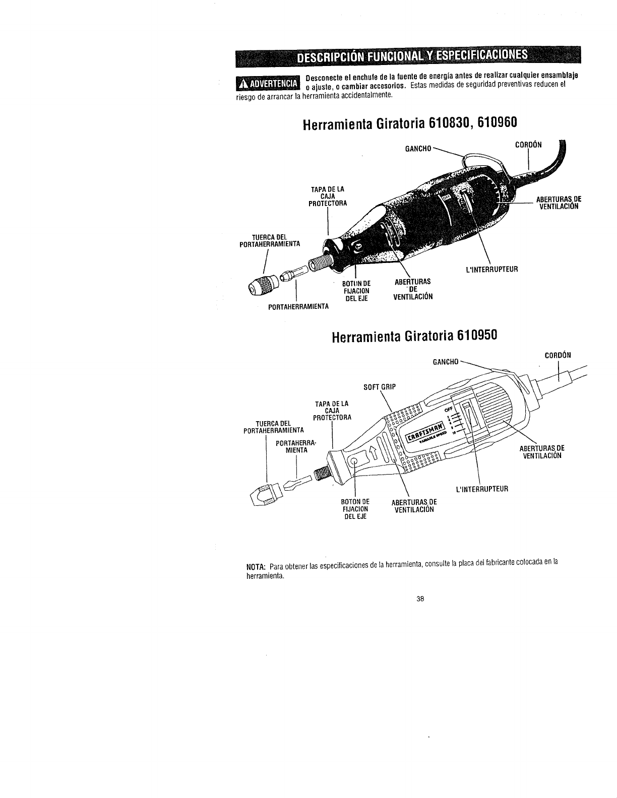
Desconecteel enchuletie la tuentede energia antesderealizar cualquierensamblaje
oajuste, o cambiar accesorios. Estasmedidasde seguridad preventivasreducefl el
riesgode arrancar la herramientaaccidentalmente.
Herramienta Giratoria 610830, 610960
COROON
TAPADE LA
CAJA
PROTECTORA ABERTURASDE
VENTILACI_)N
TUERCAOEL
PORTAHERRAMIENTA
J SOT(INDE ABERTURAS
FIJACIOH -DE
DELEJE VENTILACI(}N
PORTAHERRAMIENTA
L'INTERRUPTEUR
Herramienta Giratoria 610950
SOFTGRIP
TAPADELA
CAJA \_
TUERCADEL PROTEICTORA /'_&=%_
PORTAHERRAMIENTA ///_
PORTAHERRA-I
FIJACION
DELEJE
CORDON
GANCHO
\
ABERTURAS.DE
VENTILACION
L'INTERRUPTEUR
NOTA: Paraobtener lasespecilicacionesde la herramienta,consultela placadelfabricantecolocadaen la
herramienta.
38
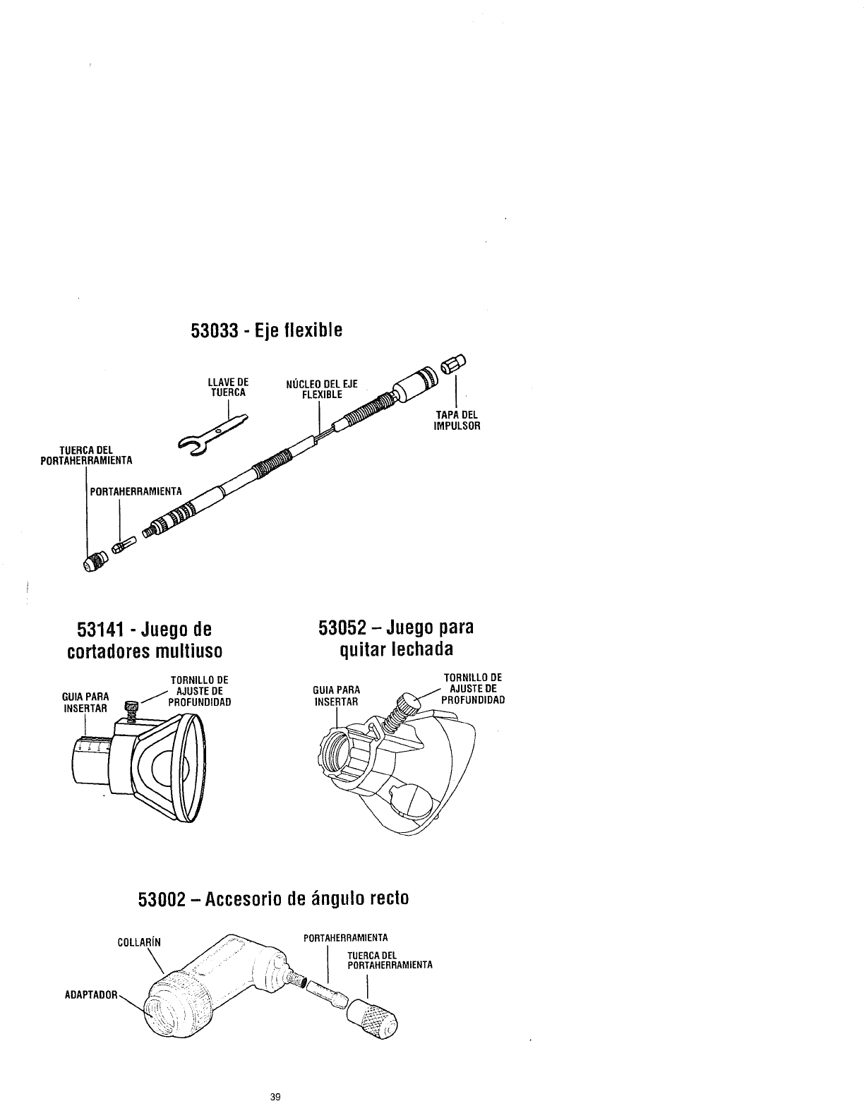
53033 - Eje flexible
LLAVE DE NUCLEO DEL EJE _ _1
TUERCA FLEXIBLE _'_/'_ I "
J_TAPA OEL
j/,,"
PORTAHE_R__
53141 - Juego de
cortadoresmultiuso 53052- Juegopara
quitar lechada
TORNILLO DE TORNILLO DE
IDADED GUIA PARA .--.. /AJUSTEoFLDE
GUIAINsERTARPARA INSERTAR I_DIDAD
53002-Accesoriode_ngulo recto
COLLA.f._ PO.TA.E...M,E..A
ADAPTADOR
39
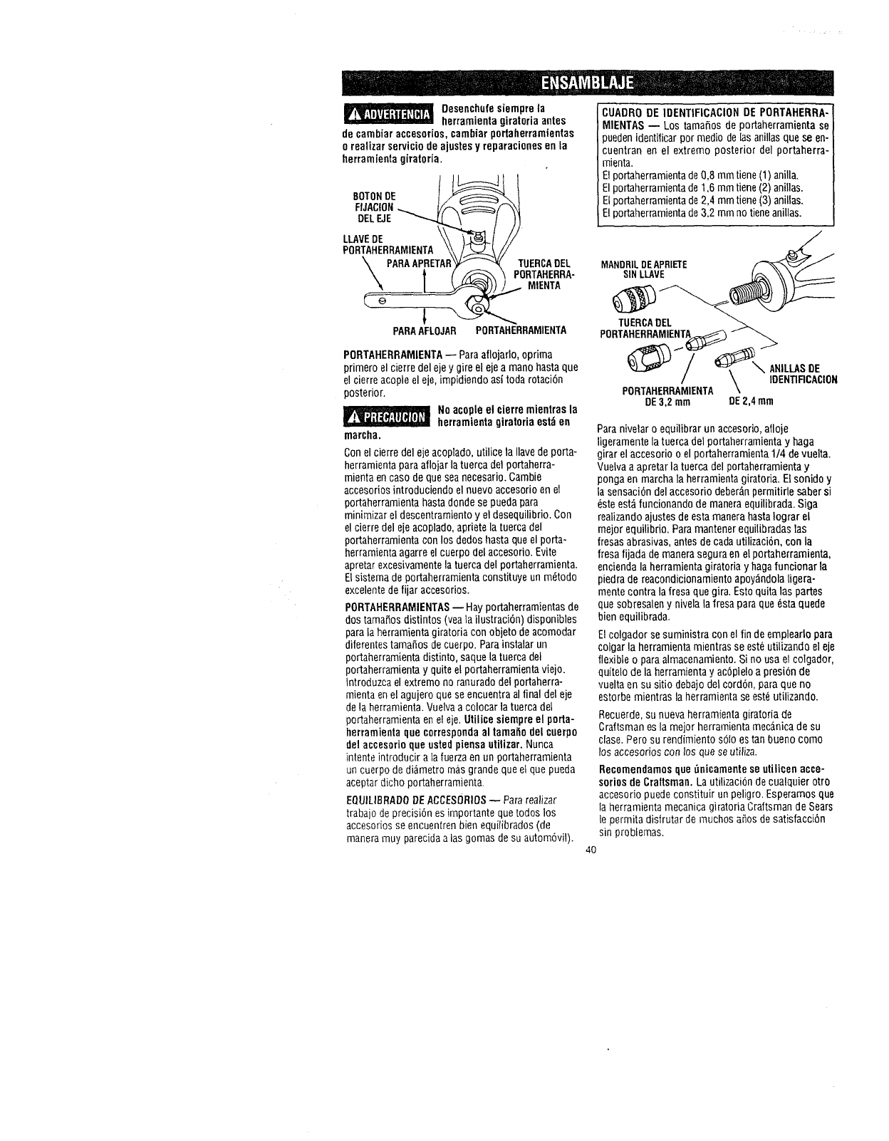
Desenchufesiempre la
herramientagiratoria antes
de cambiaraccesorios,cambiar portaherramientas
o realizar serviciode ajustesy reparacionesen la
herramientagiratoria.
FUACION_Vr_7 _
DELEJE _ \ /J)
PORTAHERRAMIENTA'_\ /°.----_.t, /
\PARAAPRETAR_ TUERCADEL
\ _ (_PORTAHERRA-
_ _- -I -_ MIENTA
PARAAFLOJAR PORTAHERRAMIENTA
PORTAHERRAMIENTA--Paraaflojarlo,optima
primero el cierre del eje ygire el ejea mano hastaque
el cierre acople el eje, impidiendo asi toda rotaci6n
posterior.
No acopleel cierremientrasla
herramientagiratoria est_en
marcha.
Con el cierre del ejeacoplado,utilice la Ilavede porta-
herramientaparaaflojar la tuerca del portaherra-
mienta en caso de que seanecesario.Gamble
accesorios introduciendo el nuevo accesorio en el
portaherramientahastadonde se pueda para
minimizarel descentramientoy el desequilibrio. Con
el cierre del ejeacoplado,apriete la tuercadel
portaherramientacon los dedos Ilasta que el porta-
herramientaagarre el cuerpodel accesorio. Evite
apretarexcesivamentela tuerca del portaherramienta.
Elsistema de portaherramientaconstituye un mdtodo
excelentede fijar accesorios.
PORTAHERRAMIENTAS-- Hay portaherramientasde
dos tamafios distintos (yeala ilustraciOn) disponibles
parala herramienta giratoria con objeto de acomodar
diferentes tamafios de cuerpo. Parainstalar un
portaherramienta distinto, saque la tuerca del
portaherramienta y quite el portaherramientaviejo.
Introduzcael extremo no ranurado del portaherra-
mienta en el agujero que se encuentraalfinal del eje
de la herramienta.Vuelvaa colocar la tuerca del
portaherramientaen el eie. Utilice siempre el porta-
herramientaque correspondaal tamafiodelcuerpo
delaccesorioqueustedpiensautilizar. Nunca
intenteintroducirala fuerzaen un portaherramienta
un cuerpo de diametro masgrande que el que pueda
aceptardicho portaherramienta.
EQUILIBRADODE ACCESORIOS_ Para realizar
trabajo de precision es importante que todos los
accesoriosse encuentren bien equilibrados (de
manera muy parecida a ias gomas de su automOvil).
CUADRODE IDENTIFICACIONDE PORTAHERRA-
MIENTAS-- Los tamafios de portaherramienta se
puedenidentificar por medio de lasanillas que se en-
cuentran en el extremo posterior del portaherra-
mienta.
Elportaherramientade 0,8 mmtiene (1) anilla.
Elportaherramientade 1,6 mmtiene (2) anillas.
Elportaherramientade 2,4 mm tiene (3) anillas.
Elportaherramientade 3.2 mm no tiene anillas.
MANDRILDEAPRIETE
SIN LLAVE
TUERCADEL
PORTAHERRAMIENTA_
_,_-._'_ ....C_ y- _._ ...-->
PORTAHERRAMIEN'rA\
DE3,2 mm DE2,4 mm
Para nivelar o equilibrar un accesorio,afloje
ligeramente la tuerca del portaherramientay haga
girar el accesorio o el portaherramienta1/4 de vuelta.
Vuelvaa apretarla tuercadel portaberramientay
ponga en marchala herramientagiratoria. Elsonido y
la sensaciOndel accesorio deberD,n permitirle saber si
este est_funcionando de maneraequilibrada. Siga
realizando ajustesde esta manera hastaIograr el
mejor equilibrio. Paramantener equilibradas las
fresas abrasivas, antes de cadautilizaciOn,con la
fresa fijada de manerasegura en el portaherrarnienta,
enciendala herramienta giratoria y hagafuncionar la
piedrade reacondicionamiento apoy_ndolaligera-
mentecontra la fresa que gira. Esto quita las partes
que sobresaleny nivelala fresa para que 6staquede
bien equilibrada.
Elcolgador se suministra conel fin de emplearlo para
colgar la herramienta mientras se esWutilizando el eje
flexible o para almacenamiento.Si no usa el colgador,
quitelo de la herramienta y acOpleloa presiOnde
vuelta en su sitio debajodel cordon, para que no
estorbe mientras la herramienta seesW utilizando.
Recuerde,su nueva herramientagiratoria de
Craftsman es la mejor herramientamecanica de su
clase. Pero su rendimiento solo estan bueno como
los accesorios con los que seutiliza.
Recomendamos que_nicamente se utilicen acce-
soriosde Craftsman.La utilizaciOnde cualquier otro
accesorio puede constituir un peligro. Esperamosque
la herramienta mecanica giratoria Craftsmande Sears
le permita disfrutar de muchos aOosde satisfacciOn
sin problemas.
4O
MANDRILDE APRIETESIN LLAVE:El mandril de
aprietesin Ilave sujeta diversos accesorios con
tamafios de cuerpo de 1/32 a 1/8 de pulgada y estd
disefiado para accesorios de servicio ligero, come
brocastaladradoras, tambores de lijar, acceserios de
pulir, cepillosde alambre y de cerdas, y ruedasde
corte.Elmandril de aprietesin Ilavele permite
cambiarlos accesorios con lrecuencia, rapidezy
facilidad.En el case de aplicaciones que pueden
generargrandes fuerzas en la broca, o si usted no
puedegenerar una presi6n de aprietecon los dedos
suficiente come parasujetar firmemente la broca,
debeutilizar la Ilave de tuerca suministrada para
ayudar a sujetar firmemente la broca.
ColocacJ6ndel mandril de aprietesin Ilave y una
brocaaccesorio
_ea yentienda el manual para
el use del mandrilde apriete
sin]lave con la herramienta. Introduzcay apriele
lirmementeel cuerpodel accesoriobien a londoen
las mordazasdel mandril. Si un accesorio no est;_
isujeto correctamente en el interiorde las mordazas de
un mandril, dicho accesoriopuede aflojarse y salir
despedidodurante el use. y podria golpearlesa usted
o alas personas que se encuentrenpresentes.
Accione nuevamenteel bot6n de fijaci6n del eje,
introduzcael cuerpo del accesorio en el mandril y
apriete el mandril con los dedoshasta que el cuerpo
delaccesorio est_sujeto firmemente.
Enel case de brocas taladradorasde tamafio
peque_o,cierre el mandril basra el punte en que ia
broca justo quepaen 61;luego, apriete firmemente el
mandril. Esto ayuda a centrar la broca correctamente
en el mandril de apriete sin Ilave.En algunas
aplicacionesde gran fuerza,come la remeci6n de
metal,el corte de Iosetaso el fresade de Iosetas,ta
broca (cortadores de carburo de tungsteno,
cortadores de alta velecidad, brocasde fresadora o
cortadoresde leseta) y el mandril secalentar_nsi se
sobrecarganduranie perfodos de tiempo
prolongados. La sobrecargadel mandril puedehacer
que labroca se afloje y patine. Se recomiendaqueen
estos tipos de aplicaciones la broca se sujete
firmementeen el mandril con la Ilave de tuerca
suministrada y que se trabajeaintervalos para
permitir que la broca y el mandril se enffien.Si la
broca patina, la herramientacomenzar_a vibrar
excesivamente.Estoes una indicaci6n de que usted
debe apagarla herramienta, reposicionary apretar la
broca, y luego dejar que la herramientafuncione sin
carga durante unos minutesparaenfriarse.
Elmandril debelimpiarse de vez en cuando para
rnantenerlofuncionando correctamente, Simplemente
quite el mandril de la herramientay golpee
suavementela punta del mandril sobre una superficie
planapara quitar todos los residuessueltos que
tenga.Enalgunasaplicaciones,es posible queel
mandril de aprietesin Ilavese aprietedurante el use.
Si estosucede,afl6jelo suavementeutilizandela Ilave
de tuerca incluida en eljuego de herramienta
giratoria.
41
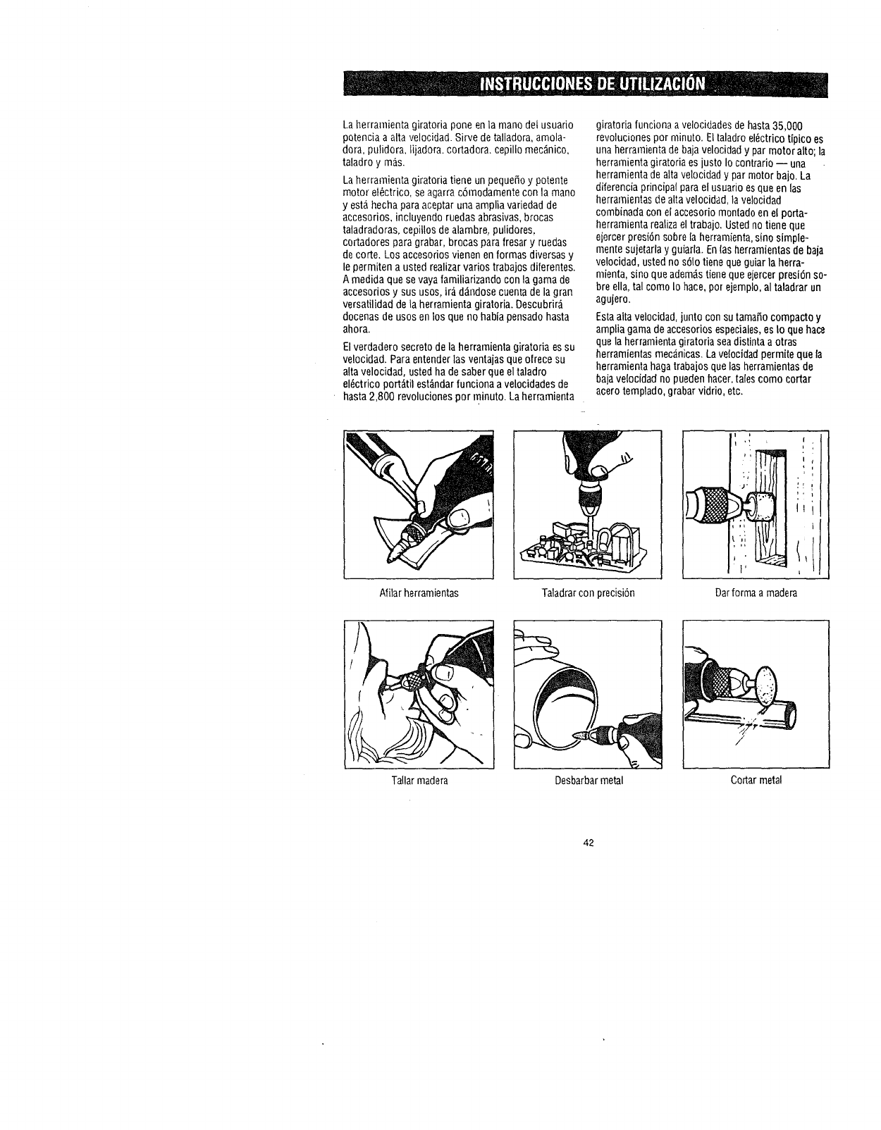
La herramienta giratoria gone en la mano dot usuario
potencia a alta velocidad. Sirve de talladora, areola-
dora, pulidora, lijadora, cortadora, cepillo mec_nico,
taladro y mas.
La herramienta giratoria tiene un pequefio y potente
motor el_ctrico, se agarrac6rnodamente con la mano
y esta hecha para aceptar una amplia variedad de
accesorios, incluyendo ruedas abrasivas,brooas
taladradoras, cepillos de alambre, pulideres,
cortadores para grabar, brocas parafresar y ruedas
de corte. Los accesorios vienen en formas diversas y
le permiten a usted realizarvarios trabajos diferentes.
A medida que se vaya familiarizando con la gama de
accesorios y sus usos, ir_ d_ndose cuenta de la gran
versatilidad de la herramienta giratoria. Descubrir_
docenas de usos en los que no habia pensado hasta
ahora.
Elverdadero secretode la herramienta giratoria es su
velocidad. Para entenderlas ventajasque ofrece su
alta velocidad, usted ha de saber clueel taladro
el6ctrico port_til est_ndarfunoiona a velocidades de
hasta 2,800 revoluciones por minuto. La herramienta
giratoria funciona a velocidades de hasta35,000
revoluciones pot rninuto. Eltaladro el6ctricotipico es
una herramienta de bajavelocidad y par motor alto la
herramienta giratoria es justo Io contrario -- una
herramienta de altavelocidad y par motor bajo. La
diferencia principal para el usuarioes queen las
herramientas de altavelocidad,la vdocidad
cmnbinada con el accesorio montadoen el porta-
herramienta realizael trabajo. Ustedno tiene que
eiercer presi6n sobreia herramienta,sino simple-
monte sujetarla y guiarla. Enlas herramientas de baja
velocidad, usted no s61otiene queguiar la herra-
mienta, sino queadem&stieneque ejercer presi6n so-
bre ella, tal como Io hace,por ejemplo,al taladrar un
agujero.
Estaalta velocidad,junto con sutamafio compacto y
amplia gama de accesoriosespeciales,es Io que hace
que la herramientagiratoria seadistinta a otras
herramientas mecdnicas.La velocidadpermite que la
herramienta hagatrabajos que las herramientas de
baja velocidad no puedenhacer,tales como cortar
acero templado, grabar vidrio, etc.
Afilarherramientas
Tallarmadera
I
I
TaIadrarcon precisi6n Darforma a madera
Desbarbarmetal Cortarmetal
42
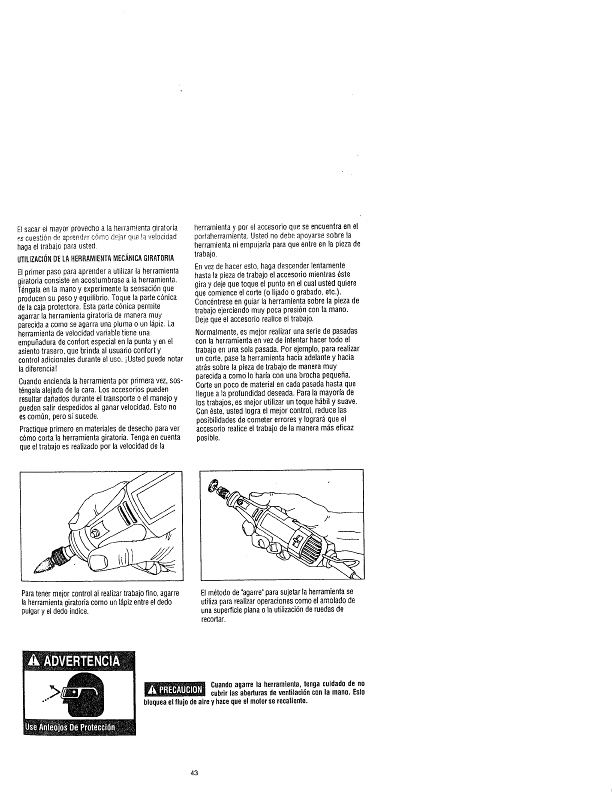
Elsacar elmayor provecho a la herr3mientagiratoria
_scuestiOnde aprendt_rc6mo d_iar que !a ve!ocidad
hagael trabaio para usted.
UTILIZACI6NDELAHERRAMIENTAMEC,4NICAGIRATORIA
Elprimer paso para aprendera utitizar la herramienta
giratoria consiste en acostumbrase a la herramienta.
T6ngalaen ta manoy experimente la sensaci6nque
producensu peso y equilibrio. Toque la parle c6nica
de la caja protectora. Estaparte c6nica permite
agarrar la herrarnientagiratoria de manera muy
parecidaa como se agarrauna plurna o un I_piz.La
herramientade velocidad variable tiene una
empu_adurade confort especial en la punta yen el
asientotrasero, que brinda al usuario confort y
control adicionalesdurante et uso. iUsted puedenotar
la diferencia!
Cuandoenciendaia herramienta por primera vez,sos-
t6ngala alejadade la cara. Los accesorios pueden
resultardafiados durante el transporte o el manejo y
puedensalir despedidos al ganar velocidad. Esto no
escornish,perosf sucede.
Practiqueprimero en materialesde desechoparaver
c6mocorta la herramientagiratoria. Tenga en cuenta
queel trabajo es realizadopor la velocidad de ta
herrarnientay por el accesorio que se encuentraen el
portaherramienta. Usted no debe apoyarsesobre la
herramienta ni empujarla para que enlre en ta pieza de
trabajo.
En vez de hacer esto, hagadescender ]entamente
hastala pieza detrabajo el accesorio mientras _ste
gira y dejeque toque el punto en el cual usted quiere
que eomienceel corte (o lijado o grabado, etc.).
Conc_ntreseen guiar la herramienta sobre la pieza de
trabaio ejerciendo muy poca presi6n con la mano.
Deje queel accesorio realice el trabajo.
Normalmente, es mejor realizar una serie de pasadas
con laberramienta en vez de intentar hacertodo el
trabajo en una sola pasada. Por ejemplo,para realizar
un corte, pasela herramientahacia adelante y hacia
atr_.,ssobre la pieza de trabajo de manera muy
parecida a como Io haria con una brocha pequefia.
Corte un poco de material en cada pasada hastaque
Ilegue a la profundidad deseada. Para la mayoria de
los trabajos, es mejor utilizar un toque h_bil y suave.
Con 6ste. ustedtogra el mejor control, reduce las
posibilidades de cometer errores y Iograr_ que el
accesoriorealice el trabajo de la manera m_s eficaz
posible.
Paratener mejor controlal realizartrabajofino, agarre
laherramientagiratoriacomo un I_pizentre el dedo
pulgary eldedo indice.
El m_todode"agarre"parasujetarla herramientase
utiliza para realizaroperacionescomo el amoladode
unasuperficieplanao la utilizaci6nde ruedasde
recortar.
lCuandoagan'ela herramienla,tengacuidadodeno
cubrirlasaberturasdeventilaci6nconla mano.Esto
bloqueaelflujodeairey hacequeel motorserecaliente.
43
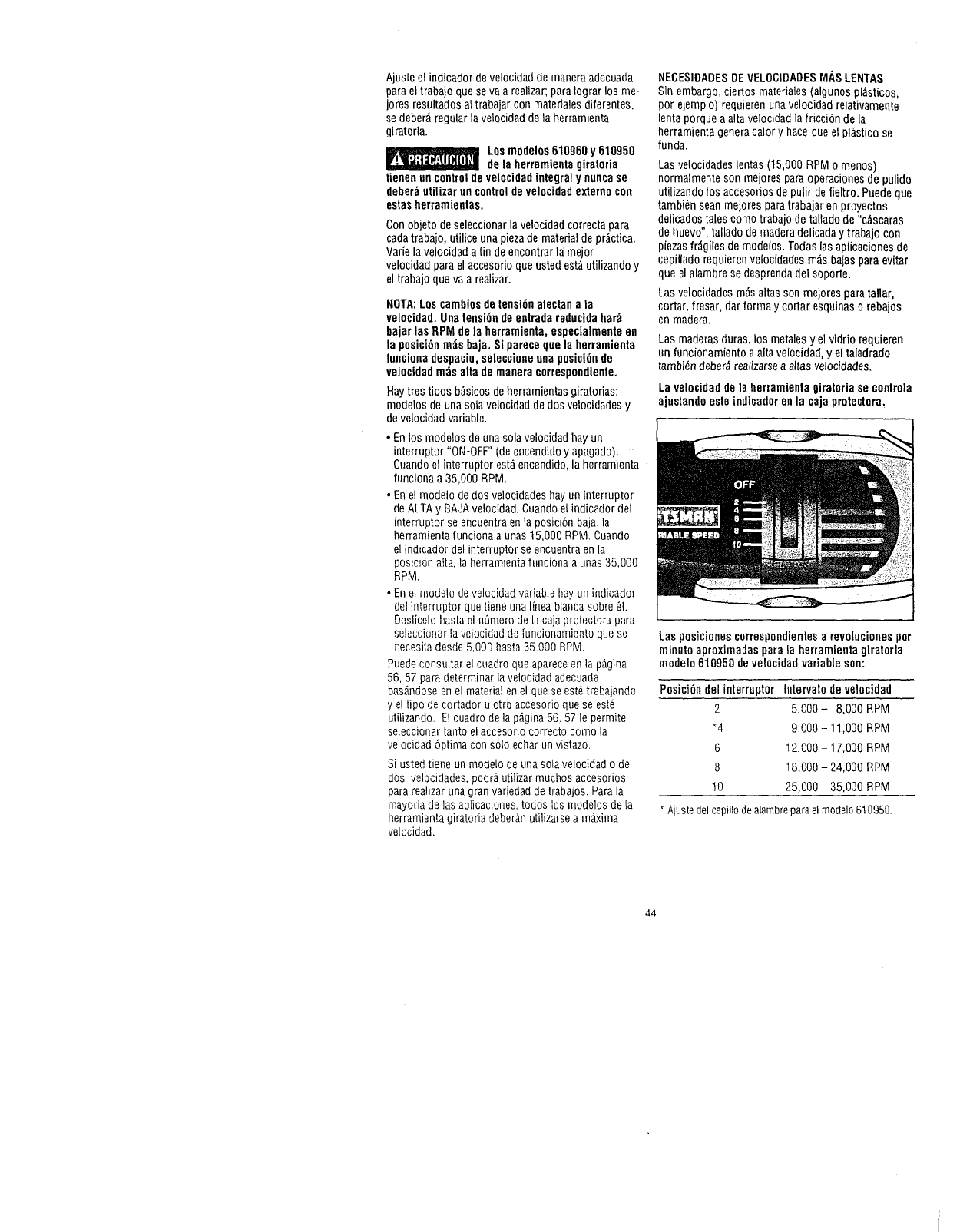
Ajuste el indicador de velocidadde maneraadecuada
parael trabajo que seva a realizar;para lograr los me-
jores resultadosal trabajar con materialesdiferentes.
se deber_ regular la velocidad de ta herramienta
giratoria.
Los mndelos610960 y 610950
de la herramieotagiratoria
tienen un controldevelocidadintegraly nuncase
deber_utilizar un controldevelocidadexternocon
estasherramientas.
Con objeto de seleccionar la velocidadcorrecta para
cadatrabajo, utilice una piezade materialde prgctica.
Varie la velocidad a fin de encontrar la meier
velocidad para elaccesorio que ustedest_ utilizandoy
eltrabajo que va a realizar.
NOTA:Loscambiosdetensidnafectan ala
velocidad. Unatensi6nde entradareducidahar_
bajar las RPM de la herramienta, especialmenteen
la posici6nrods baja. Si pareceque la herramienta
funcionadespacio,seleccioneuna posicidnde
velocidadmilsalta de manera correspondiente.
Haytres tipos b_sicos de herramientas giratorias:
modetos de una sola velocidad de des velocidades y
develocidad variable.
• En los modelos de una sola velocidad hay un
interrupter "ON-OFF' (deencendidoy apagado).
Cuandoel interrupter est_iencendido,la herramienta
funciona a 35,000 RPM.
• En el modelo de dos velocidadeehayun interrupter
de ALTAy BAJAvelocidad. Cuandoel indicador del
interrupter se encuentraen ]a posici6n baja, la
herramienla funciona a unas 15,000 RPM. Cuando
el indicador del interrupter se encuentraen la
posici6n a!ta, la herramientafunciona a unas35,000
RPM.
• En el modelo de velocidadvariable hay un indicador
delinterrupter que tiene una Ifneablancasobre 61.
Deslicelohastael nOmerede la caja 9rotectora para
seleccionar la velocidadde funcionamiento que se
neeesitadesde 5,000 hasta 35000 RPM.
Puedeconsu[tar e! euadro que apareceen la p,.'_gina
56, 57 para determinar laveloeidadadecuada
bas_,ndoseen el material enel que seest_ trabaiando
y elripe de eortadoru ot[o accesorio que se est6
utilizando. E!euadro dela p_gina 56, 57 le perrnite
se[eccienar tanto el accesorio eorreetocome la
velocidad 6ptima con s61oechar un vistazo.
Si usted tiene un mode[o de una sola velocidad o de
dos wlocidades, podr;i utilizarmuchos accesories
para rea!izarunagran variedad de trabaios. Para la
mayoria de iasaplicaciones,lodes los rnodelosde la
herramient.agiratoria deber_n utilizarsea maxima
velocidad.
NECESIDADESDEVELOCIDADESMASLENTAS
Sin embargo, ciertos materiales (algunos pl_sticos,
per eiemplo) requieren unavelocidad relativamente
lentaporque a alta velocidadla fricci6n de la
herramienta genera calory hace que el plD,stico se
funda.
Lasvelocidadeslentas (15,000 RPM o menes)
normalmente son mejores para operacionesde pulido
utilizando los accesoriosde pulir de fieltro. Puede que
tambi6n sean mejores para trabajar en proyectos
delicados tales come trabajo de tallado de "c_.scaras
de huevo", tallado de maderadelicaday trabajo con
piezasfrdgiles de modelos. Todas las aplicaciones de
eepillado requierenvelocidades rods bajas para evitar
que el alambrese desprenda del soporte.
Lasvelocidades mds altas son meiores para tallar,
cortar, fresar, dar forma y cortar esquinas o rebajos
en madera.
Las maderasduras, los metalesy el vidrio requieren
un funcionamiento a altavelocidad, y el taladrado
tambi_ndeber_ rea/izarsea altas velocidades.
Lavelocidadde la herramientagiratoriase controla
ajustandoesteindicadorenla caja protectora.
Lasposicienescorrespondientesa revolueionesper
minute aproximadas para la herramientagiratoria
modelo 610950 deve!ocidadvariable son:
Posici6n del interrupter Intervalo de velocidad
2 5.000- 8,000 RPM
+4 9,000 - 11,000 RPM
6 12,000- 17,000 RPM
8 18,000- 24,000 RPM
10 25,000 - 35,000 RPM
* A!uste del cepille de alambre para el modelo 610950.
44
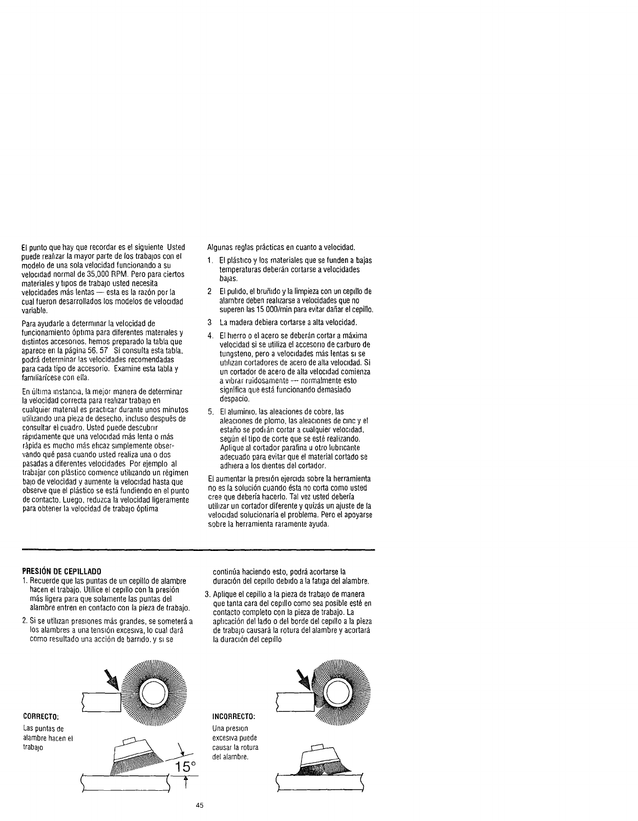
Elpunto que hay que recordar es el siguiente Usted
puedereahzarla mayor parte de los trabalos con el
modelode una sola velocidad funcionando a su
veloc_dadnormal de 35,000 RPM Pero para ciedos
materialesy tipos de trabajo usted necesita
velocidadesm;_slentas-- esta esla raz6n por la
cual fueron desarrollados los modelos de veloctdad
variable.
Paraayudade a determinar la velocidad de
funcionamiento 6ptima para diferentes materialesy
dlstintos accesorios, hemos preparado la tabtaque
apareceen la pdgina 56. 57 Si consulta esta tabla,
podr#,determinar las velocidades recomendadas
para cadatipo de accesorio. Examineesta tabla y
famdiarfcesecon ella.
En Oltima mstanma,la mejor manera de determinar
la velocidad correcta para reahzartraba]o en
cualquier material es pract_cardurante unos minutos
utihzandouna pieza de desecho,incluso despu_s de
consultar el cuadro. Usted puede descubnr
rapldamenteque unavelomdad rags lenta o m_s
r;pida es mucho m_.sehcazs_mplementeobser-
vando qu_ pasacuando usted realiza una o dos
pasadasa diferentes velocidades Por eiemplo al
trabajar con p!_.sticocomtenceutihzando un r6gimen
balode velocidad y aumente la velocldad hasta que
observeque el pl_,sticose est_fundiendo en el punto
de contacto. Luego, reduzcala velocidad ligeramente
paraobtener la velocidad de trabalO6ptima
Algunas reglas pr_cticas en cuanto a velocidad.
1. El pl_st_coy los materiales que sefunden a bajas
temperaturas deberan cortarsea velocidades
balas.
2 Elpuhdo,el brufiido y la limpiezacon un cepillode
alambredebenrealizarseavelocidadesque no
superenlas 15 000/rain paraevitardafiar el cepillo.
3 La madera debieracortarse aalta velocidad.
4. E1h_erroo el acero se deberancortar a m_xima
velocidad si se utiliza elaccesorio de carburo de
tungsteno, pero a velomdadesm_.slentass_se
utthzancortadores de acerode alta veloctdad.Si
un cortador de acero de altaveloc_dadcomienza
a vlbrar ruidosamente-- normalmenteesto
significa que est,, funcionando demasiado
despacio.
5. Elaluminio, las aleacionesde cobre, las
aleactonesde plomo, lasaleactonesde cinc y el
estafio se podt_n cortar a cualquier veloc_dad.
seg0nel tipo de code que se est_ realizando.
Aplique al cortador parafina u otro lubncante
adecuadopara evitar que el material cortado se
adhteraa los dtentesdel cortador.
El aumentar la presi6n ejercida sobrela herramienta
no es la soluci6n cuando esta no coda como usted
cree que deberia hacerlo. Tal vezusted deberia
utihzar un cortador diferente y quizdsun ajuste de la
velomdadsolucionaria el problema.Pero el apoyarse
sobre la herramienta raramenteayuda.
PRESIONDECEPILLADO
1. Recuerdeque las puntas de un cepilto de alambre
hacenel trabajo. Utiliceel cepdlo con la presi6n
m_s Iigera para que solamente las puntasdel
alamhreentren en contacto con la pieza de trabajo.
2. $i se utihzanpreslones mAsgrandes, se someter_ a
los alambres a unatens_6n exceslva,Io cual dar#,
como resultado una acci6n de barrido, y s_se
contin0a haciendo esto, podra acortarse la
duram6n delcepillo debtdo a la fat_gadel alambre.
3. Aplique el cepillo a ta piezade traba]ode manera
que tanta cara del cep_llocomoseaposible este en
contacto completo con la piezadetrabajo. La
aphcaci6ndel lado o del bordedel cepillo a la pieza
de trabajo causarala rotura del alambrey acortara
la duraci6n del ceplllo
CORRECTO:
Laspuntasde
atambrehacenel
traba]o
45
INCOFIRECTO:
Unapreskon
excestvapuede
causarla rotura
del alambre.
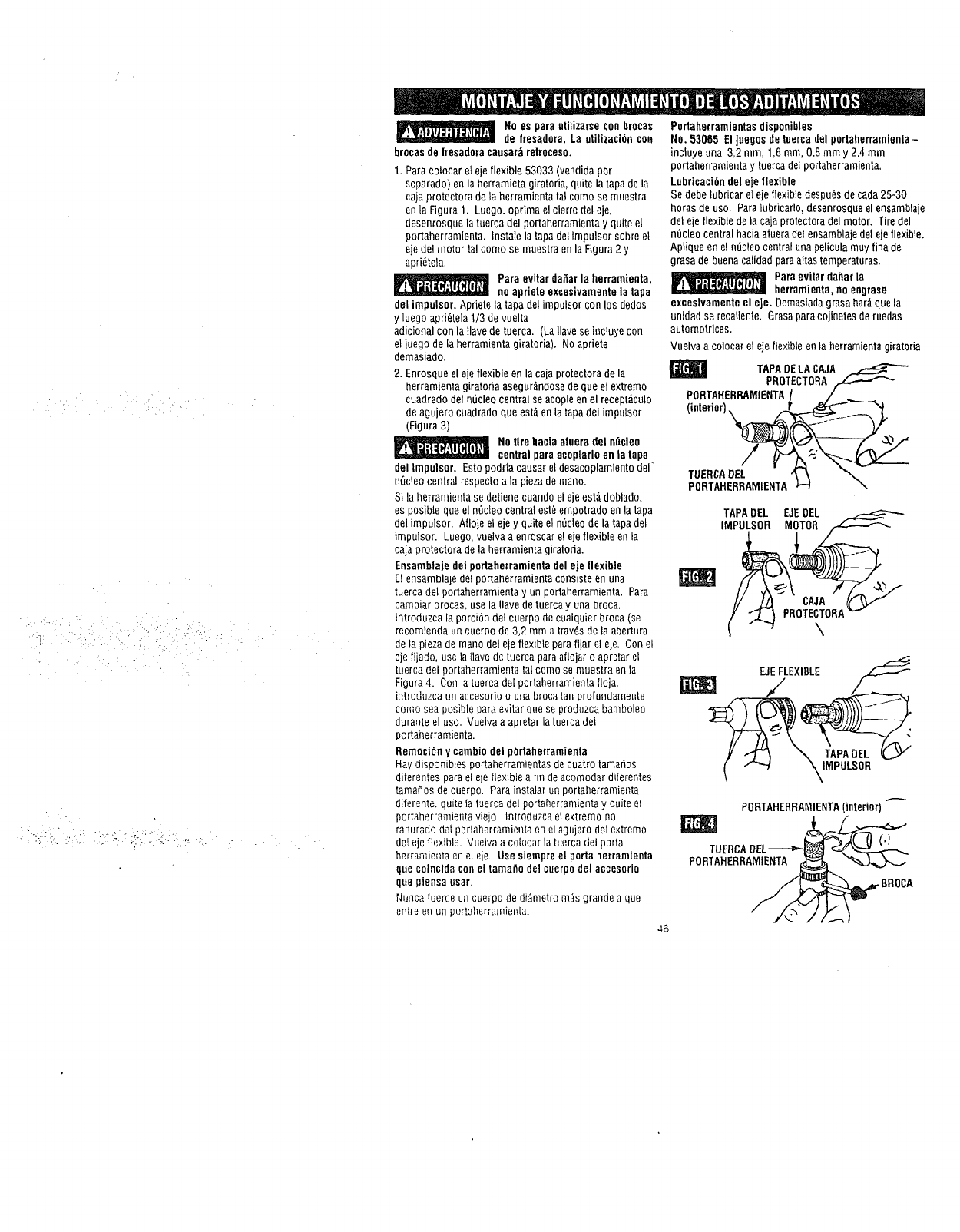
/
No es parautilizarseconbrocas
de fresadora.La utilizaci6ncon
brocasdefresadoracausar_retroceso.
1. Paracolocarel ejeflexible53033(vendidaper
separado)en la herramietagiratoria, quitelatapade la
cajaprotectorade la berramientatal comesemuestra
en la Figura1. Luego.optimael cierredeleje.
desenrosquela tuercadel portaherramientayquite e[
portaherramienta,lnstale latapadelimpulsor sobreet
ejedel motor tal comese rnuestraen la Figura2 y
apri_tela.
Para evitar dai_arla herramienta,
noapriete excesivamentela tapa
delimpulsor. Apfiete latapa delimpulsor conIns dedos
y luegoapri_telat/3 devuelta
adicionalcon la tlavede tuerca. (LaIlaveseincluye con
eljoego de laherramientagiratoria). No apriete
demasiado.
2. Enrosqueelejeflexible en lacaja protectorade la
herramientagiratoriaasegur_ndosede que elextreme
coadradodel nOcleocentral seacopleen el recept_cuto
de agujerocuadradoqueest_en la tapadel impulsor
(Figura3).
Notirehacia afueradel n,_cleo
centralparaacoplarloen la tapa
deltmpulsor. Estopodriacausarel desacoplamientodel
nQcleocentral respectoa la piezade mann.
Sila herramientase detienecuandoelejeest,,doblado,
esposibleque el n_cleocentralest_empotradoen la tapa
delimpulsor. Nloje el ejey quiteel nOcleode latapa del
impulsor. Luego,vuelvaa enroscarelejeflexible en la
cajaprotectorade la herramientagiratoria.
Ensamblajedel portaherramientadeleje flexible
Elensamblajede] portaherramientaconsisteen una
tuercadel portaherramientay un portaherrarnienta.Para
cambiarbrocas, usela Ilavedetuercay una broca,
Introduzcala porci6ndel cuerpode cualquierbroca(se
recomiendaun cuerpode 3,2 mm a tray,s de la abertura
de la piezade manndelejeflexible parafijar el eje. Conel
ejeIijado, usela ]lavede tuercaparaaflojar o apretaret
tuercadel portaherramientatalcomese muestraenla
Figura4. Conlatuercade[ portaherramientafloja,
introduzcaun accesorioo unabrocatan protundamente
come seaposibleparaevitarquese produzcabamboleo
durante eluse. Vuelvaa apretarla tuercadet
portanerramienta.
Remnci6n ycambiodel pOrtaherramienla
Haydisponibles po_aherramientasdecuatro tamales
diferentespara el eje flexiblea finde acomodardiferentes
tamales de cuerpo. Parainsta]arun portaherramienta
diferente,quitela tuercadelportaherramientay qufteel
portaherramientavieio, tntroduzcael extremeno
ranuradodelportaherramientaen elagujerode[ extreme
delejeflexible. Vuelvaa colocarlatuercadel porta
herramientaenel eie. Usesiempre el perta herramienla
que coincidaconel tamanodel cuerpodelaccesorio
que piensausar.
Nuncafuerceun cuerpode di_metro m_sgrandea que
entre en un portaherramienta.
Portaherramientasdisponibles
No.53065 El jueges detuerca[tel portaherramienta-
incluyeuna 3,2 mm, 1,6ram, 0.8 mm y 2,4 mm
portaberramientay tuercadelportaherramienta.
Lubricaci6n deleje flexible
Sedebetubricarelejeflexibledespu_sdecada25-30
horasde use. Paralubriearlo,desenrosqueelensamblaje
delejeflexible dela cajaprotectoradelmotor. Tiredel
n_cleocentralhaciaafueradelensamblajedelejeflexible.
Apliqueen el n_cleocentralunapeliculamuyfinade
grasade buenacalidadparaattastemperaturas.
Paraevitardaflarla
herramienta,noengrase
excesivamenteel eje. Demasiadagrasahar_ quela
unidadse recaliente.Grasaparacojinetesde ruedas
automotrices.
Vuelvaa colocarel ejeflexibleenla herramientagiratoria.
T.PADELAC,UA
PROTECTORA,,_
PORTAHERRAMIENTAJ /
(interior)_._j_
TUERCADEL "_ \
PORTAHERRAMIENTA_ \
TAPADEL EJEDEL
IMPULSOR MiTOR ,_
F-JEFLEXIBLE
PORTAHERRAMIENTA(interior)
(,!
TUERCA
PORTAHERRAMIENTA
46
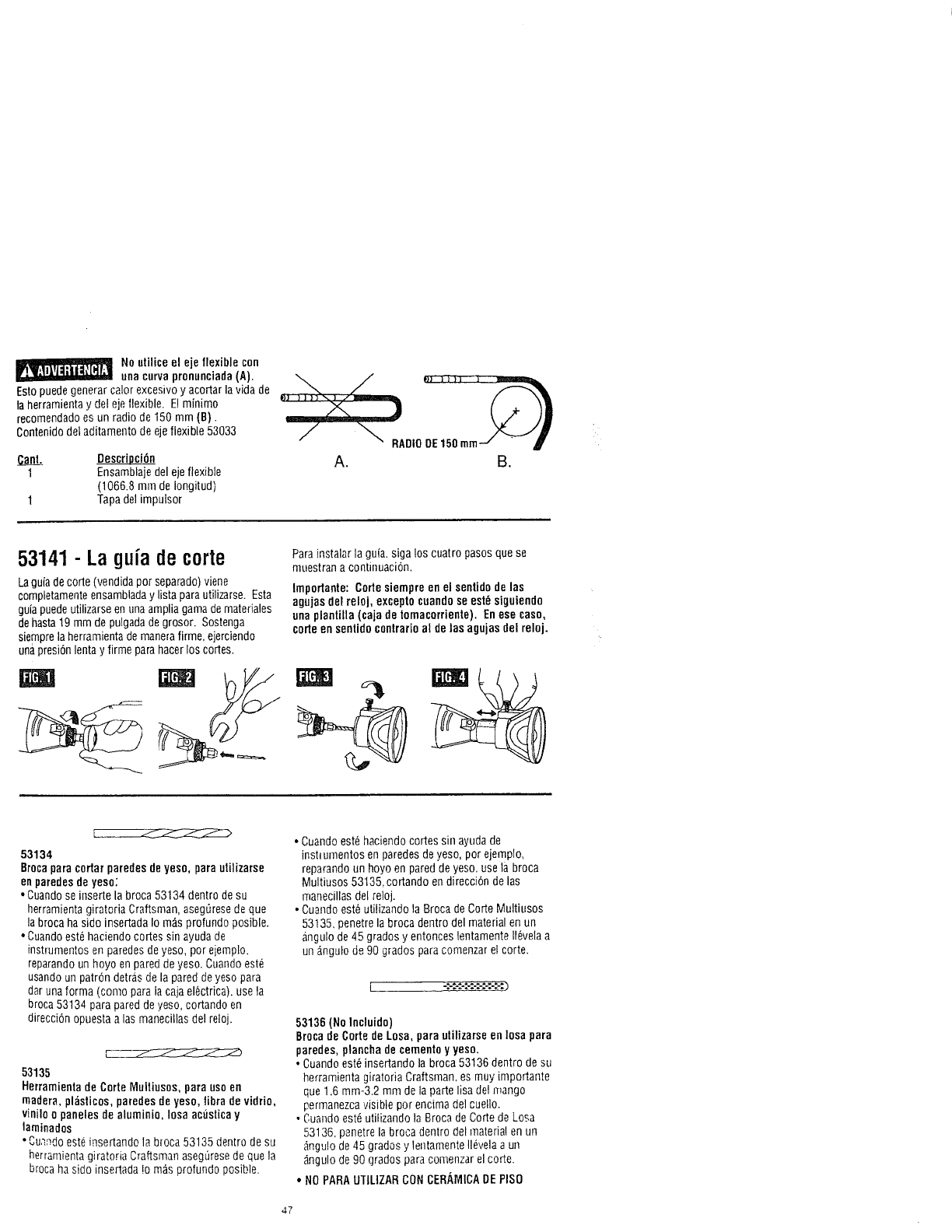
Noutilice el eje flexiblecon
ueacurvapronunciada(A).
Estopuedegenerar calorexcesivoy acoRarla vida de
la berramientay det ejeflexible. El minimo
recomendadoes un radio de 150 mm (B).
Contenidodel aditamento de ejeflexible 53033
a.O_.&BL Descripci6n
1 Ensamblajedel ejeflexible
(1066.8 mill de Iongitud)
1 Tapadel impulsor
53141 - La guia de corte
La guiade corte (vendidaper separado)viene
completamenteensambladay lista parautilizarse. Esta
guiapuedeutilizarseen una amplia gamade materiales
de hasta19 mm de pulgadade grosor. Sostenga
siemprelaherramientade manerafirme, ejerciendo
unapresi6nlentay firme parahacerlos codes.
Parainstalar la guia.siga los cuatro pasos que se
muestrana continuaci6n.
Impoflante: Cortesiempre enel sentido delas
agujas delrelej, exceptocuandose est_ siguiendo
unaplantilla (cajade tomacorriente). Enese case,
corteensentidocontrarioal de las agujasdel reloj.
53134
Brocapara cortar paredesde yeso, para utilizarse
enparedesde yese;
• Cuandoseinserte la broca 53134 dentro de su
herramientagiratoria Craftsman, asegt]resede que
labroca ha side inseRadaIo m_s profundo posible.
• Cuandoest6haciendo cores sinayuda de
instrumentosen paredesde yeso, per ejemplo.
reparandoun boyo en pared de yeso. Cuandoest_
usandoun patron detrasde la pared de yeso para
daruna forma (come para la caja el_ctrica), usela
broca53134 para pared de yeso, cortando en
direcci6n opuesta a las manecillas del reloj.
53135
Herramieetade CorteMultiusos,para useen
madera, plasticos,paredes de yeso, libra de vidrio,
viniloopanelesde aluminio, Iosa ac_sticay
laminados
•Cum_doest6insedando la broca 53135 dentro de su
herramientagiratoria Craftsmanaseg_resede que la
brocaha side insedada !o m;_sprofundo posible.
• Cuandoest_haciendo cores sin ayudade
instlumentos en paredesde yeso, per ejemplo,
reparando un hoyo en pared de yeso, use la broca
Multiusos 53135,cortando en direcci6n de las
manecillasde[ reloj.
• Cuandoest6 utilizando la Brocade CorteMultiusos
53135, penetre la broca dentro del material en un
angulo de 45 grades y entonces lentamente116velaa
un &ngulode 90 grades paracomenzar el corte.
53136 (No Incluido)
Brocade Corte deLosa, para utilizarseen ]osapara
paredes, plancha de cementoy yeso,
•Cuandoest_ insedando la broca 53136 dentro de su
berramientagiratoria Craftsman, es muy importante
que 1.6 mm-3,2 mm de la pare lisa del mango
perrnanezcavisible por encima de] cuello.
• Cuandoest_ utilizando la Brocade Code de Losa
53136. penetre la broca dentro del material en un
_ngu!ode 45 grados y lentamenteIlevela a un
_ngulo de 90 grados para comenzarel core.
•NOPARA UTILIZARCONCERAMICADE PISO
47
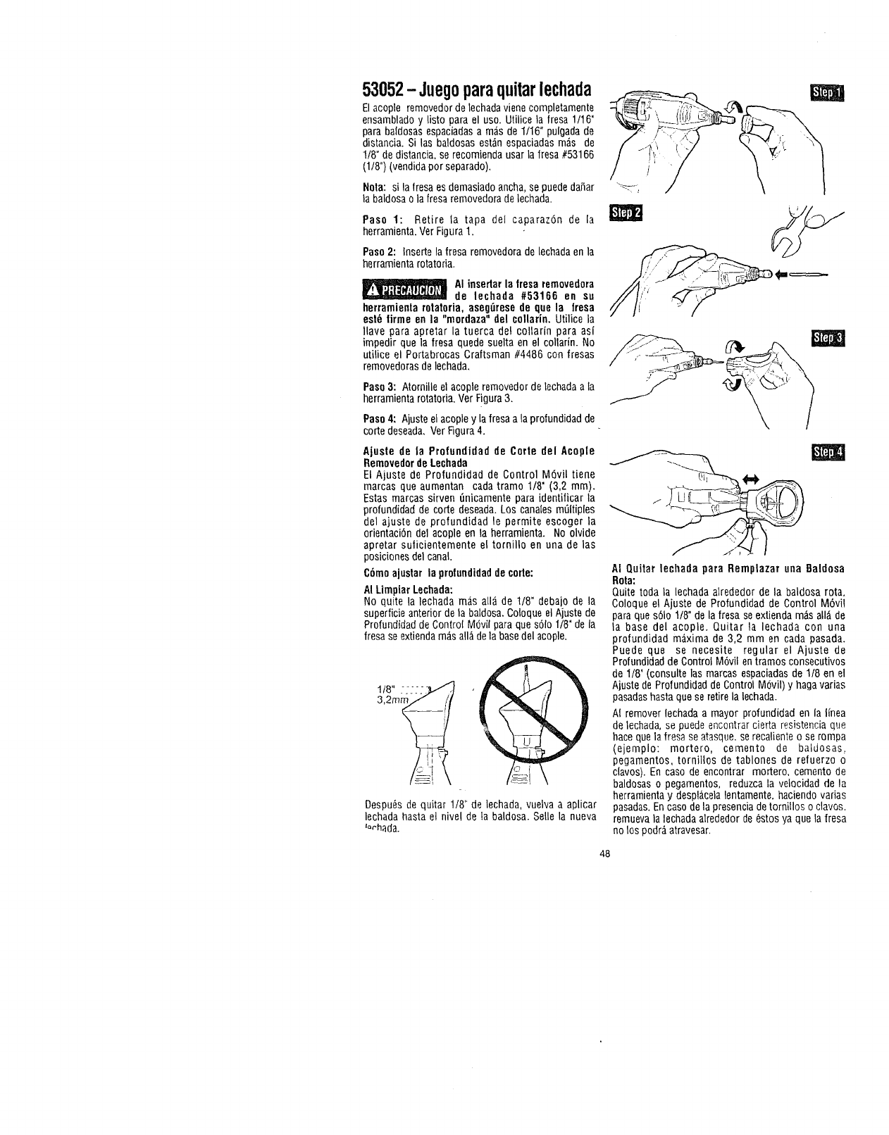
53052-Juegoparaquitarlechada
Elacople removedor de lechadav/eriecompletamente
ensambladoy listo para el uso. Utilice la fresa 1/16"
para baldosas espaciadasa m_isde 1/16" pulgada de
distancia. Si las baldosas est_n espaciadas m_s de
1/8" de distancia, se recomienda usar la fresa #53166
(1/8") (vendida por separado).
Nora: si la fresaes demasiadoancha,se puededafiar _-°,
la baldosa ola fresa removedorade lechada.
Paso 1: Retire la tapa del caparaz6n de la
herramienta.Ver Figura 1.
Paso 2: Inserte la fresa removedorade lechadaen la
herramientarotatoria.
AI insedar la fresa removedora
de lechada #53166 en su
herramienta rotatoria, aseg_iresede que la fresa
est6 lirme en ]a "mordaza" del collarin. Utilicela
Ilave para apretar la tuerca de! coltarin para asi
impedir que la fresa quede suelta en el collarin. No
utilice el Portabrocas Craftsman #4486 con fresas
removedorasde lechada.
Paso3: Atornille el acople removedorde lechadaa la
herramienta rotatoda. Ver Figura 3.
Paso4: Ajusteel acople y lafresa a la profundidadde
code deseada, Ver Rgura 4.
Ajuste de la Profundidad de Carte del Acople
Removedorde Lechada
El Ajuste de Profundidad de Control M6vil tiene
marcas que aumentan cada tramo 1/8" (3,2 mm).
Estas marcas sirven _nicamente para identificar la
profundidad de code deseada. Los canales m_ltiples
del ajuste de profundidad le permite escoger la
orientaci6n del acople en la herramienta. No olvide
apretar sulicientemente el tornillo en una de las
posicionesdel canal.
C6moajustar la profundidaddecorte:
AILimpiar Lechada:
No quite la lechada m_s all_ de 1/8" debajo de la
superficie anterior de la baldosa. Coloqueel Ajuste de
Profundidad de Control Mdvil para que s61o118"de la
fresa se extiendam&sall& de la basedel acople.
Despu6s de quitar 1/8" de lechada, vuelva a aplicar
lechada hasta ei nivel de la baldosa. Selle la nueva
_orhada.
AI Quitar lecharla para Remplazar una Baldosa
Rota:
Quite toda la lechada atrededor de la baldosa rota.
Coloque el Ajuste de Profundidad de Control M6vi!
para que s61o1/8"de la fresa se extienda m:_sall_ de
la base del acople. Quitar la lechada con una
profundidad m_xima de 3,2 mm en carla pasada.
Puede que se necesite regular el Ajuste de
Profundidad de Control M6vil en tramos consecutivos
de 1/8" (consulte las marcas espaciadasde 1/8 en el
Ajuste de Profundidad de Control M6vil) y haga varias
pasadashasta quese retire la lechada.
AI remover lechada a mayor profundidad en la linea
de lechada, se puede encontrar cierta resistencia que
hace que lafresa se atasque, serecaliente o se rompa
(ejemplo: mortero, cemento de batdosas,
pegamentos, tornillos de tablones de refuerzo o
clavos). En caso de encontrar mortero, cemento de
baldosas o pegamentos, reduzca la velocidad de la
herramientay despl_celalentamente, haciendo varias
pasadas.En caso de la presenciade tornillos o clavos.
remuevala lechada alrededor de6stos ya que la fresa
no Ins podr_iatravesar.
48

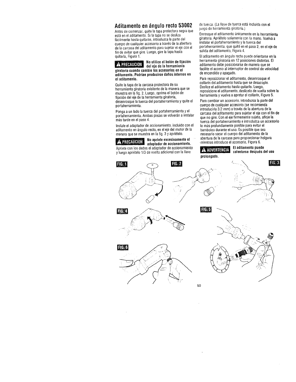
Aditamentoen ngulo recto53002
Antes de cornenzar,quite la tapa protectora negra que
est_ en el aditamento. Si la tapa no se desliza
f_cilmente hasta quitarse, introduzca la parte del
cuerpo de cualquieraccesorio a tray,s de la abertura
de la carcasadot aditamento para sujetarel eje con el
fin de evitarque gire. Luego, gire la tapa hasta
quitarla, Figura 1.
No utiliceel bot6nde fijacion
del eje dela herramienta
giratoriacuandocambielosaccesoriosenel
aditamento.Podrianproducirsedafiosinternesen
el aditamento,
Quitela tapa de la carcasaprotectora de su
herramienta giratoria existente de la maneraque se
muestra en lafig. 2. Luego, optima el bot6n de
fijaci6n del ejede la herramientagiratoria,
desenrosque latuerca del portaherramientay quiteel
portaherramienta.
Pongaa un lado la tuerca del portaherramientay el
portaherramienta.Ambas piezassevolver__na instalar
m_,stardeen el paso4.
Instale el adaptador de accionamiento,incluido con el
aditamento en _ngulo recto, en el ejedel motor de la
maneraque se muestra en la !ig. 3 y apri_telo.
Noaprieteexcesivamenteel
adaptadorde accionamienta.
Aprietecon los dedos eladaptadorde accionamiento
y luego apri_telo 1/3 de vuelta adicional con la Ilave
/
de tue_ca. (LaHavede tuerca est_incluida con el
luego de herramientagiratoria.)
Enrosqueel aditarnento 0nicamenteen la herramienta
giratoria. Apridtelo solamentecon la mano. Vuelvaa
instalar el portaherramientay latuerca del
portaherramienta,que quit6 enel paso2, en el eje de
salida deladitamento, Figura4.
Eladitamento en angulo rectopuede orientarseen la
herramientagiratoria en 12 posiciones distintas. El
aditamento debeposicionarse de manera que se
facilite el accesoal interruptor de control de velocidad
de encendidoy apagado.
Para reposicionar el aditamento,desenrosque el
collarin del aditamento hastaqua se desacople.
Desliceel aditamento hasta quitarlo. Luego,
reposicione eladitamento, deslicelo de vuelta sabre la
herramientay vuetva a apretarel collarin, Figura 5.
Para cambiar un accesorio, introduzca la parte del
cuerpo de cualquier accesorio (se recomienda
introducirla 3.2 mm) a tray,s de la abertura de la
carcasadel aditamento para sujetar el ejecon elfin de
que no gire. Con el ejefirmemente sujeto, afloje la
tuerca del portaherramientae introduzca un accesorio
Io m_s profundamenteposiblepara evitar el
bamboleo durante el usa. Esposible que sea
necesariosacarel cuerpo del aditamento de la
abertura de la carcasapara proporcionar holgura
mientras introduce el accesorio, Figura 6.
prolongado.
50
Eladitamentopuede
calentarsedespu_sdelusa
=) !ii ,_7:-
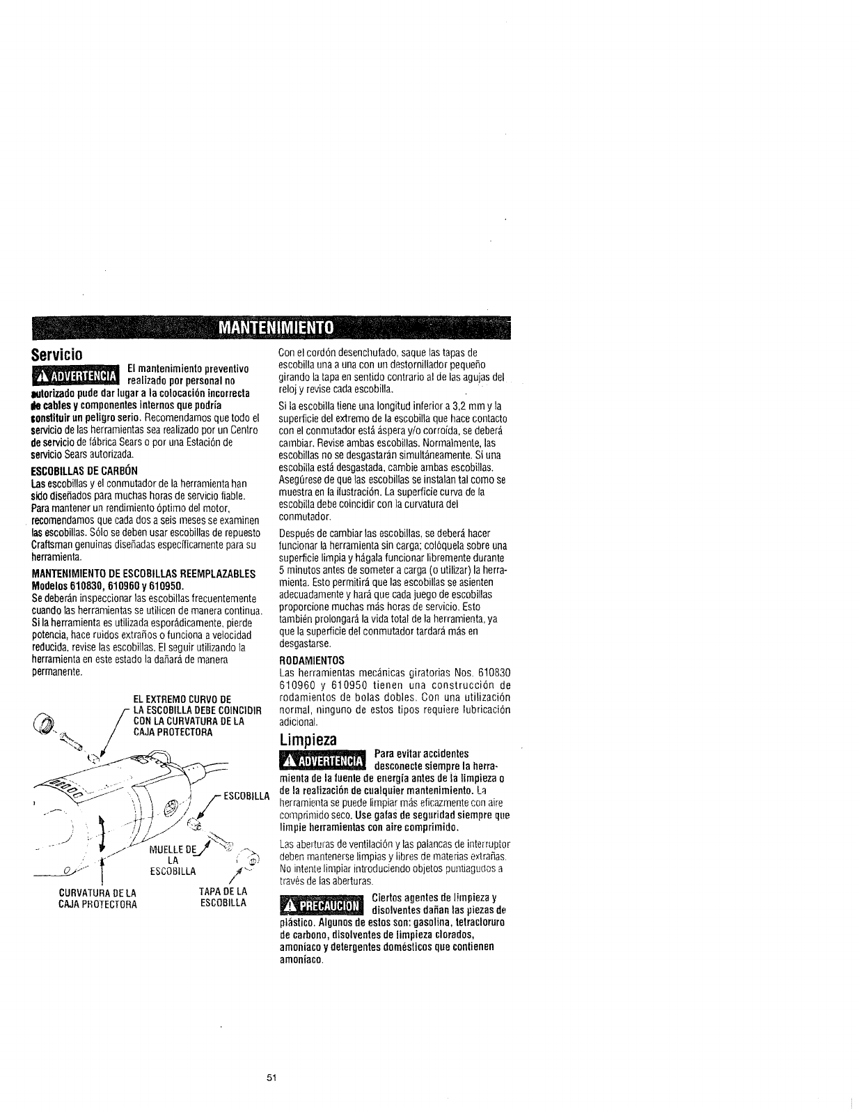
Servicio
El mantenimientopreventivo
realizadoporpersonalno
zwtorizadopude[tar lugara la cotocaci6nincorrecta
lie cablesy componentesinternosquepodria
tonstituir unpeligroserio. Recomendamosque todo el
serviciode las herramientassearealizadopor un Centro
deservicio de f_bricaSearso por una Estaci6nde
sen,ioio Searsautorizada.
ESCOBILLASDECARBON
I.asescobillasyelconmutador de laherramientahan
sidodisefiadospara muchashorasde servicioliable.
Paramantenerun rendimientooptimo delmotor,
recomendamosquecadados a seis mesesseexaminen
lasescobillas.$61osedebenusar escobillasde repuesto
CraftsmangenuinasdiseSadasespecificamenteparasu
herramienta.
MANTENIMIENTODEESCOBILLASREEMPLAZABLES
Modelos610830, 610960 y 610950.
Sedeber_ninspeccionarlas escobillasfrecuentemente
cuandolas herramientasse utilicen de maneracontinua.
Silaherramientaesutilizadaespor_,dicamente,pierde
potencia,haceruidos extraSoso funcionaa velocidad
reducida,revise las escobilias.Elseguir utilizandola
herramientaen esteestado lada_arade manem
permanente.
ELEXTREMOCURVODE
(F_ FLAESCOBILLADEBEC01NCIDIR
/CONLACURVATURADELA
_--J-- ,;_ / CAJAPROTECTORA
LA _ ",,,'
_____._.__._QJ¢" ESCOBILLA /
CURVATURA DELA TAPADE LA
CAJAPROTECTORA ESCOBILLA
Conel cord6n desencllufado,saquelas tapasde
escobillaunaa una con un destornillador pequefio
girandola tapaen sentido contrarioal de lasagujas del
reloj y revisecadaescobilla.
Si laescobillatieneuna Iongitud inferiora 3,2 mm y la
supediciedel extremode la escobillaque hacecontacto
con el conmutadorest_;_speray/o corroida,se deber_
carnbiar.Reviseambasescobillas. Normalmente,las
escobillasno se desgastaransimult_neamente.Si una
escobillaest_desgastada,cambie ambasescobiilas.
Aseg6resede quetas escobillasseinstalantal como se
muestraen la ilustraci6n.La superficie curvade la
escobilladebecoincidir con lacurvaturadel
conmutador.
Despudsde cambiar tasescobiilas,se deber;_hacer
funcionar la herramientasin carga; col6quelasobre una
superficie limpiay h_galafuncionar libremente durante
5 minutos antesde someter a carga(o utilizar) la herra-
rnienta.Estopermitir;_que lasescobillasse asienten
adecuadamentey har;_que cadajuegode escobillas
proporcionemuchasm;_shorasde servicio.Esto
tambi6n prolongar_lavida totalde la herramienta,ya
que la superficiedel conmutadortardaramasen
desgastarse.
RODAMIENTOS
Las herramientas mec_nicas giratorias Nos. 610830
610960 y 610950 tienen una construcci6n de
rodamientos de bolas dobles. Con una utilizaci6n
normal, ninguno de estos tipos requiere lubricaci6n
adicional.
Limpieza
Paraevitar accidentes
desconectesiempre la herra-
mieotade la luenlede energiaantes deia limpiezao
de la realizaci6ndecualquiermantenimiento. La
herramientase puedelimpiar m_s eficazmentecon aire
comprimidoseco.Use galas de segt_ridadsiempre que
limpie herramientasconaire compfimido.
Lasabetturasdeventilaci6ny las palancasde interruptor
debenmantenerselimpias y libres de materiase×tra_as.
Nointentelimpiar introduciendoobjetos puntiagudosa
trav_sde las aberturas.
Ciertosagentes de limpieza y
disolventesdafianlas piezasde
ptastico.Algunosde estos son:gasolina, tetracloruro
de carbono,disolventesde limpieza clorados,
amoniacoydetergentesdom_sticos quecontienen
amoniaco.
51
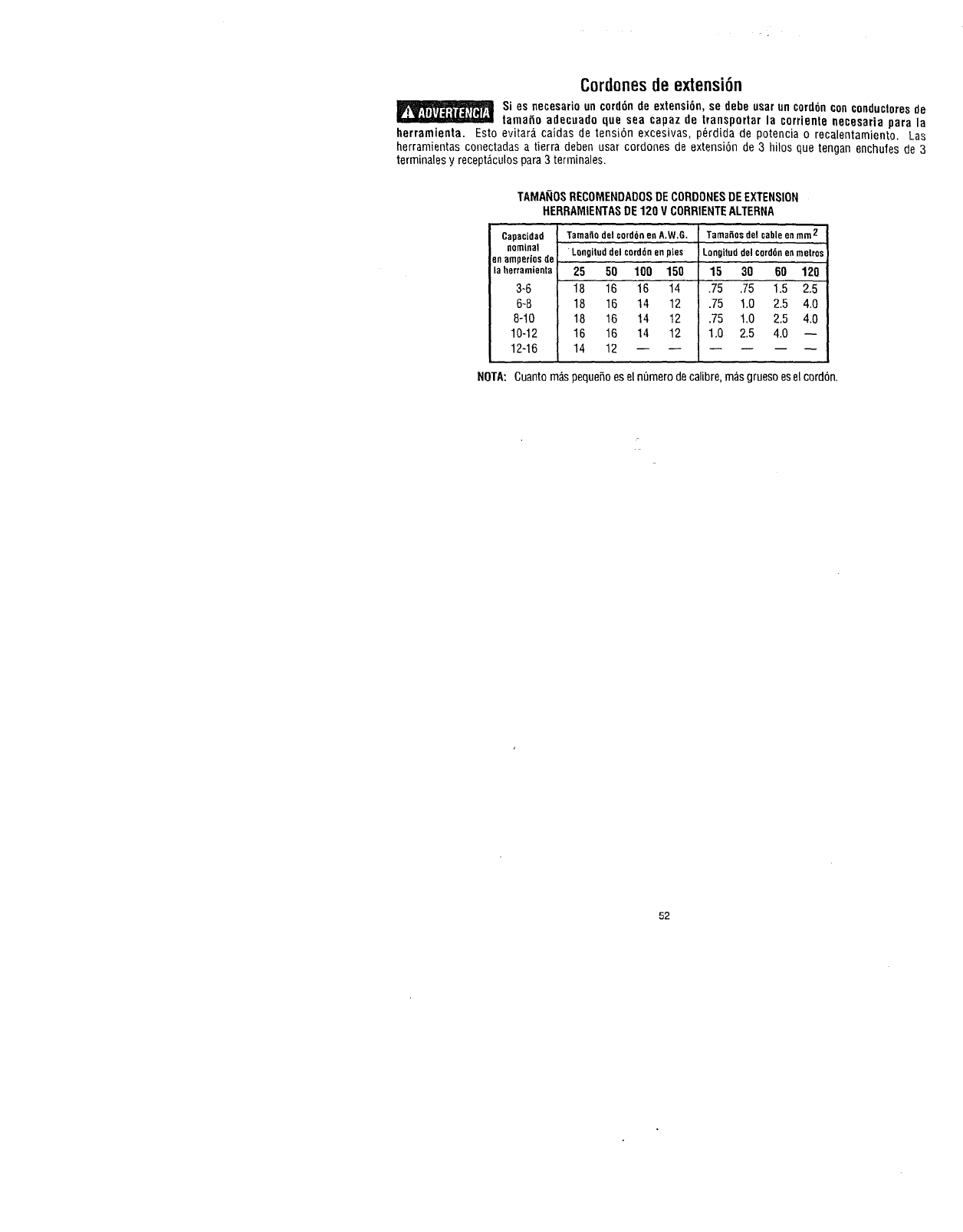
Cordonesde extensi6n
Si es necesario un cord6n de extensi6n, se debe usar un ¢ord6ncon conducloresde
lamafio adecuado que sea capaz de transportar la corriente necesaria para la
herramienta. Esto evitar_, caidas de tensi6n excesivas, p_rdida de potencia o recalentamiento. Las
herramientas conectadas a tierra deben usar cordones de extensi6n de 3 hilos que tengan enchufes de 3
terminales y recept_culos para 3 terrninales.
TAMANOSRECOMENDADOSDE CORDONESDEEXTENSION
HERRAMIENTASDE120 V CORRIENTEALTERNA
Capacidad
nominal
enamperiosde
laherramienta
3-6
6-8
8-10
10-12
12-16
Tamaflodelcord6nenA.W.G,
Longiluddelcord6nenpies
25 50 10D 150
18 16 16 14
18 16 14 12
18 16 14 12
16 16 14 12
14 12
Tamaflosdelcableenmm2
Longituddelcord6nenmetros
15 30 60 120
.75 .75 1.5 2.5
.75 1.0 2.5 4.0
.75 1.0 2.5 4.0
1.0 2.5 4.0 --
NOTA: Cuanto m_spequefioesel n_mero de calibre,m_sgruesoesel cord6n.
52
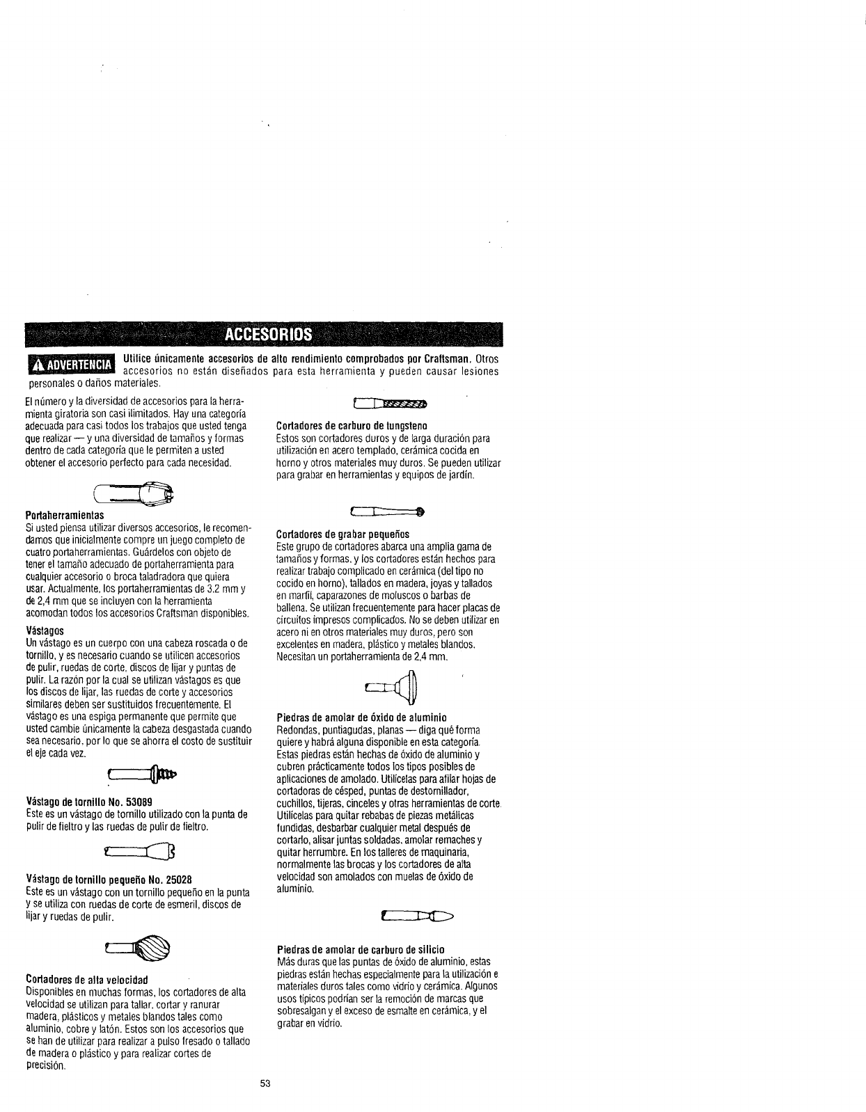
Utilice [inicamente accesoriosde alto rendimientocomprobadosporCraltsman. Otros
accesorios no estan dise_ados para esta herramienta y pueden causar lesiones
personaleso da_os materiales.
Eln0meroy la diversidadde accesoriosparala herra-
mientagiratoriason casi ilimitados.Hayuna categoria
adecuadapara casitodos los trabajos que ustedtenga
querealizar-- y unadiversidad detamafios y formas
dentrode cadacategoriaque le permitena usted
obtenerelaccesorio perfectoparacadanecesidad.
Porlaherramieotas
Siustedpiensauti]izardiversos accesorios,lerecomen-
damosqueinicialmentecompre un juego completode
cuatroportaherramientas.Gu_rdeloscon objetode
tenerel tamai_oadecuadode portaherramientapara
cualquieraccesorioo brocataladradoraque quiera
usar.Actualmente,los portaherramientasde3.2 mmy
de 2,4 mm que seincluyencon laherramienta
acomodantodoslos accesoriosCraftsmandisponibles.
V_slagos
Un v;Mago es un cuerpo con unacabezaroscadao de
tornillo, yes necesadocuandose utilicen accesorios
de pulir,ruedasde corte, discos de lijar y puntasde
pulir. La raz6nporla cual se utilizanv_.stagoses que
los discosde lijar, las ruedasde cortey accesorios
similaresdebenser sustituidosfrecuentemente.El
v&stagoesuna espigapermanenteque permiteque
ustedcambieL]nicamentela cabezadesgastadacuando
seanecesario,por Io quese ahorra el costo desustituir
elejecadavez.
V_stagodelornillo No. 53089
Estees un v;istagode tornillo utilizadoconta puntade
pulirde fieltro y lasruedasde pulir de fieltro.
V;_stagodetornillopequeiloNo. 25028
Estees un v_stagocon un tornillopequeSoen lapunta
y seutilizacon ruedasde corte de esmeril,discos de
lijar y ruedasdepulir.
Corladoresde carburodetungsteno
Estossoncortadores duros y de largaduraci6n para
utilizaci6nen acerotemplado,cer;_micacocida en
homo y otros materialesmuy duros.Sepuedenutilizar
para grabaren herrarnientasy equiposde jardin.
Cortadoresdegrabar pequefios
Estegrupo de cortadoresabarcaunaamplia gamade
tama5osyformas, y loscortadoresest_.nhechospara
realizartrabajocomplicadoencer;_mica(deltipo no
cocidoen homo), talladosen madera,joyasy tallados
en marfil,caparazonesde moluscoso barbasde
ballena.Seutilizanfrecuentementeparahacerplacasde
circuitos impresoscomplicados.Nosedebenutilizaren
aceroni enotros materialesmuyduros,peroson
excelentesen madera,pl_sticoy metalesblandos.
Necesitanun portaherramientade 2,4 ram.
Piedras deamolar de6xido de aluminio
Redondas,puntiagudas,planas-- digaqu6 forma
quierey habr;_alguna disponibleen estacategorfa.
Estaspiedrasest_nhechasde6xido dealuminio y
cubren pr;_cticamentetodos los tipos posiblesde
aplicacionesdeamolado.Utilicelasparaafilarhojasde
cortadorasde c6sped,puntas dedestornillador,
cuchillos,tijeras,cincelesy otrasherramientasde corte
Utilicelaspara quitarrebabasde piezasmet_licas
fundidas,desbarbarcualquiermetaldespu6sde
cortaflo, alisarjuntas soldadas,amolarremachesy
quitar herrumbre.En lostalleresdemaquinada,
normalmentelas brocasy los cor_dores de alia
velocidadsonamoladosconmuelasde6xido de
aluminio.
Cortadoresde alia velocidad
[3isponiblesen muchasformas, los cortadoresde alia
velocidadseutilizan para tallar,cortar y ranurar
madera,pl_sticosy metalesblandostales como
aluminio,cobre y lat6n. Estosson los accesoriosque
sehande utilizar pararealizara pulsofresadoo tallado
de maderao pl_sticoy para realizarcortesde
precisi6n.
Piedras de amolar decarburode silicio
M_sdurasquelas puntasde6xidode aluminio,estas
piedrasest_.nhechasespecialmenteparalautilizacione
rnatedalesdurostalescomo vidfioy cer_mica.Ngunos
usostipicos podrianser laremoci6nde marcasque
sobresalgany el excesode esmaiteen cer_mica,y el
grabaren vidrio.
53

Accesorios para pulir
Entreestos accesoriosse encuentranunapunta depulir
impregnaday una ruedade pulir impregnadapara dar
un acabadoliso alas superficiesmet_iicas;unapunta
de pulir de fieltro y una ruedade pulirdefieltro, y una
ruedade pulirde tela.Todosestosaccesoriosse utilizan
pardpulirpl_sticos,metales,joyeriay pequefiaspiezas.
Laspuntasde pulir dejanunasuperficiemuy lisa,pero
seobtieneun bdtlomayor utilizandoruedasdefieltro o
de telay compuestopara pulir.
Paraobtenerlos mejores resultados,losaccesorios
de pulirdebenutilizarsea velocidadesque no
superenlas 15 O00/min.Consultela secci6n
Velocidadesdeluncionamientoparainlormarse
sobreel ajusleadecuadodela velocidadde la
herramienta.
Ruedasabrasivasde6xido dealuminio
Se utilizan paraquitar pintura,desbarbarmetal y pulir
acero inoxidabley otros metales.Disponibtescongrano
finoy mediano.
Cepillosdealambre
HayIres formas diferentesdecepillosde alambredis-
ponibles.Paraoblenerresulladcs6primes, las
escobillasde alambredebenutilizar_ea velocidades
que noseansuperioresa 15 O00/min.Consu]tela
secci6nVelocidadesdefuncionamientopara
informarsesobreel ajusteadecuadodela velocidad
de la herramienta.Estoscepillosquitanherrumbrede
lasherramientasy otrassuperficiesmet_licas,y limpian
y brufienpiezasmet_licas.Utilfcelosparatrabajostales
comola limpiezade conexionesel_ctricaspara
asegurarsede quelaconducci6nesbuena.
Cepillosdecerda
Estoscepillosconstituyenexcelentesherramientaspara
limpiar objetosde plata,joyasy antigi_edades.Los
cepillosde cerdapuedenutilizarsecon un compuesto
para pulir conel fin de Iograrunalimpiezao un pulido
m_,sr_pido.
Accesoriospara lijar
Los discos de lijar est_n hechosparaacoplarseenet
v&stagoNo. 25028.Se puedenutilizarpara casitodos
los trabajospequefiosde lijadoqueusted tengaque
realizar,desdela fabdcaci6nde modeloshastael
acabadode muebtesfinos. Adem&s,est_el lijador de
tambor, un diminuto tambor queencajaenla
herramientagiratoriay que haceposibledar forma a
madera,alisarlibra devidrio, lijaren elinterior de curvas
y otros lugaresdiffcilesy realizarotrostrabajos de lijado.
Cambie lasbandasde lijar det tambora medidaque se
vayan desgastandoy pierdanel grano.Las bandas
vienenen gradosfinos y gruesos.
Ruedasde corte
Estosdelgadosdiscosde esmerilo delibra de vidrio se
utilizanpara rebanar,cortar y operacionessimilares.
Utilicelospara cortar cabezasde pemoy tuercas
agarrotadaso paravolvera ranurarunacabezade
tornillo que est_tan da5adaqueno permitausar un
destornillador.Buenasparacortar cable BX,varillas
peque_as,tuber[a,cable,y para cortaragujeros
rectangularesen chapamet;_lica.
Brocasde fresadoradealia velocidad
Parafresar, incrustary modajarenmaderay otros materialesblandos. UtilicelasconelaccesoriodefresadoraNo.
53099de Craftsmany la mesadeperfiladora/fresadoraNo. 53034 deSears.
54
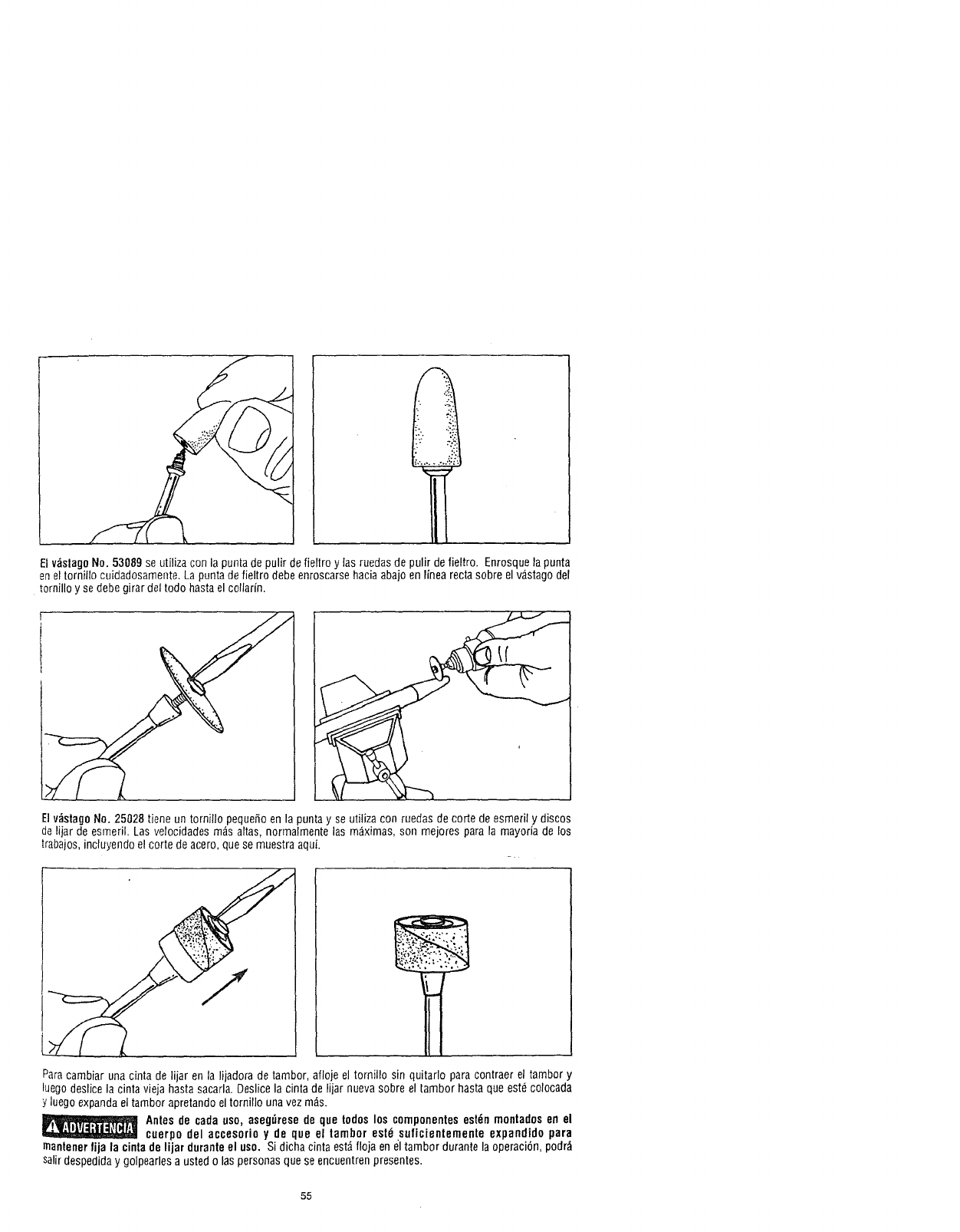
Elv_slagoNo. 53089 se utiliza con la punta de pulir de fieltro y las ruedas de pulir de fieltro. Enrosque la punta
enel tornillo cuidadosamente. La punta de fieltro debe enroscarse hacia abajo en linea recta sobre elv,_stagodel
tornillo y se debe girar del todo hastael collarfn.
ElvdstagoNo. 25028 tiene un tornillo pequeSo en la punta y se utiliza con ruedas de corte de esmeril y discos
de lijar de esmeril. Las velocidades m_s altas, norrnalmente las m&ximas, son mejores para la mayorJade los
trabajos,incluyendo el corte de acero, que se muestra aqui.
J
Paracambiar una cinta de lijar en la lijadora de tambor, afloje el tornillo sin quitarlo para contraer el tambor y
luego deslice la cinta vieja hastasacarla. Deslice la cinta de lijar nuevasobre el tambor hastaque est_ colocada
y luego expandael tambor apretando eltorniNo una vez m_s.
_ ntes de cada uso, aseg_rese de que todoslos componentesest_n monladosen el
cuerpo del accesorio y de que el lambor estO suficientemente expandido para
mantenerfija la cinta de lijar durante el uso, Si dicha cintaest_ floja en eltambor durantela operaci6n, podr&
salir despediday golpearles a ustedo las personasque se encuentrenpresentes.
55
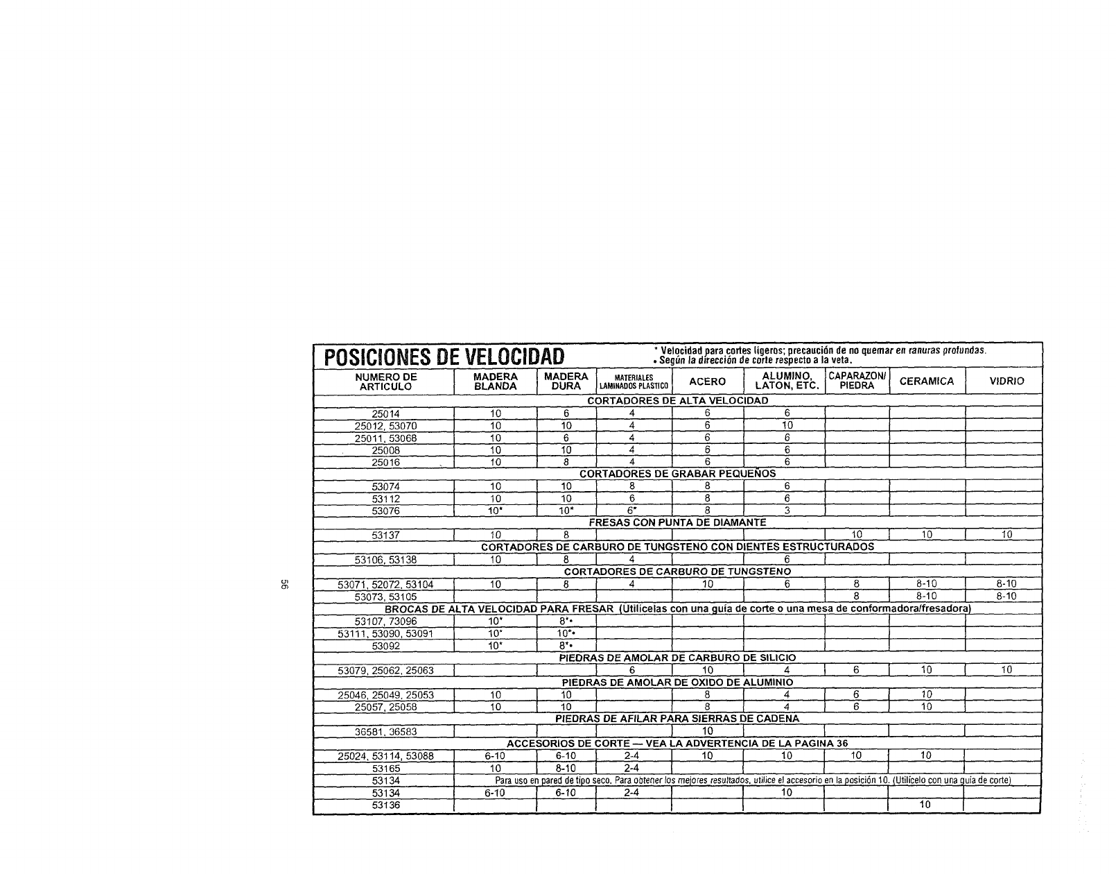
POSIC!0NESDEVELOCIDAD .'Vel°cidadparac°rtesiigeros;precaucidnden°quemarenranuraspr°fundaSsegdnla dlreccibn de code respec,o a ,a veta.
ARTICULO BLANDA DURA LAMINAD0SPLASTCO ACERO LATON, ETC, PEDRA CERAMICA VIDRIO
CORTADORES DE ALTA VELOCIDAD
25014 10 6 4 6 I 6
25012, 53070 10 i . 10 4 6 I 10
25011 53068 10 6 4 6 6
25006 10 10 4 6 6
25016 10 84 6 6
CORTADORES DE GRABAR PEQUEIT.IOS
53112 10 10 6 86
53076 10" 10" 6" 8 3
FRESAS CON PUNTA DE DIAMANTE
53137 I 10 ,I 8 I I I I 10 t 10 ! 10
CORTADORES DE CARBURO DE TUNGSTENO CON DIENTES ESTRUCTURADOS
5310653138 I 10 I 8 I 4 I I 6 I I I
CORTADORES DE CARBURO DE TUNGSTENO
53071,52072,53104 I 10 I8 I 4 I 10 I 61818-1018-10
53073, 53105 8 8-10 8-10
BROCAS DE ALTA VELOOIDAD PAP,J_ FRESAR (Utilicelas con una 9uia de corte ouna mesa de conformadora/fresadora)
53111, 53090, 53091 10" 10".
53092 10" 8*,
PIEO_sDEAMO'ARDECARBURODES_UC,O
53079, 25062,25063 I I ,I 6 I 10 I 4 I 6 I 10 I t0
PIEDRAS DE AMOLAR DE OXlDO DE ALUMINIO
25057, 25058 10 10 846 10
PIEDRAS DE AFILAR PARA SIERRAS DE CADENA
36581,36583 I I I I lo lI I I
ACCESORIOS DE CORTE -- VEA LA ADVERTENCIA DE LA PAGINA 36
6-10 I 1010 I6"10 J 108-10 I_ 2-4
25024,53114,53088
53165
53134
53134
53136
Para uso en pared de tipo seco. Paraobtener los mejores resultados, utiliceel accesorio en la posiciOn 10. {Utilicelo con una gufa de torte)
6"1°I °-1°f 2"4I I'° I I ,0 I
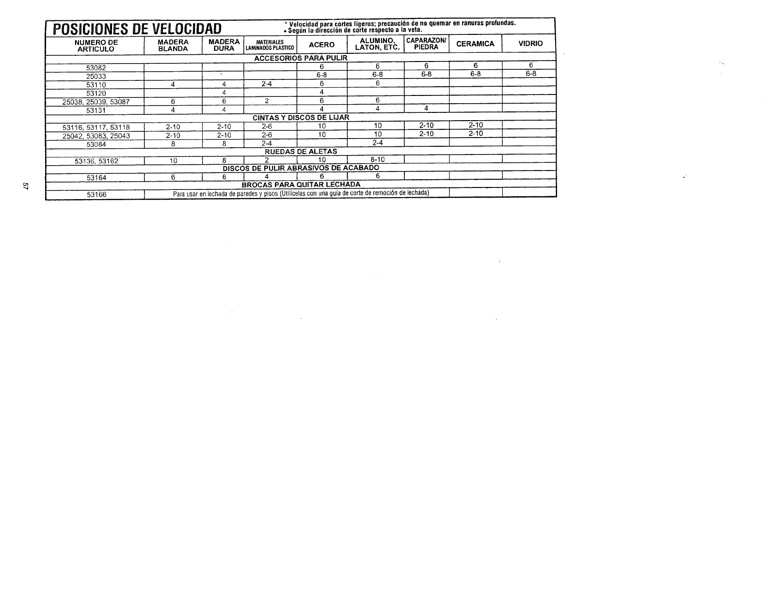
* Velocidad para codes ligeros; precauc!Gn de no quemar en ranuras profundas.
POSJCIONESDEVELOCIDAD ._eg_n|aolrecci6noecorterespect0alavela.
I MA°E"AI_A°_"A I A'u_'"°'c'PA_°" !°LA.OA°O_ .ATO..ETC._,E°_C_.A.,CA
6-8 6-8
4 4
4
6 6 6
4 4 4 4
2-10 2-10 10 [2-10
2-10 2-10 10 I 2-10
8 8 2-4
1o I 8 I
6 I I
Para usar en lechada de paredes y pisos (Utilicelas con una guia de corte de remociOn de lechada)
NUMERO DE
ARTICULO
53082
25033
53110
53120
25038,25039,53087
53131
53116, 53117, 53118 ] 2-10
25042, 53083,25043 I 2-10
53084
53136,53162 I I I
53164 I I I
53166 I I I
MATERIALES IACERO
LAMINADOSPLASTIC01
I
ACCESORIOS PARA PULIR
I ° °
6-8 6-8
2-4 6 6
4
2 6
4
ClNTAS Y DISCOS DE LIJAR
2-6 10
2-4
RUEDAS DE ALETAS
I 2 t lO I 8-1o
DISCOSDEPUURAB_SlVOSDEACABADO
6 I 4 t 6 ! 6
BROCAS PARA QUITAR LECHADA
VIDRIO
6
6-8

For in-home major brand repair service:
Call 24 hours a day, 7 days a week
1-800-4-1MIY-HOiMIES"(1-800-469-4663)
Parapedirserviciodereparaci6na domicilio- 1-800-676-5811
In Canadafor all your service and parts needs call -1-800-665-4455
Au Canadapour tout le service ou les pi_ces
For the repair or replacement parts you need:
Call 7 am - 7 pm, 7 days a week
1-800-366-PART(1-800-366-7278)
Para ordenarpiezasconentregaa domicilio- 1-800-659-7084
For the location of a Sears Parts and Repair Center in your area:
Call 24 hours a day, 7 days a week
1-800-488-1222
For information on purchasing a Sears Maintenance Agreement
or to inquire about an existing agreement:
Call 9 am - 5 pm, Monday- Saturday
1-800-827-6655
TheServiceSideof Sears."
2610913327 7/01 PRINTED IN U.S.A.
