Craftsman 917 256544 Owners Manual
917256544 917256544 CRAFTSMAN TRACTOR - Manuals and Guides L0709251 View the owners manual for your CRAFTSMAN TRACTOR #917256544. Home:Lawn & Garden Parts:Craftsman Parts:Craftsman TRACTOR Manual
CRAFTSMAN Lawn, Tractor Manual L0709251 CRAFTSMAN Lawn, Tractor Owner's Manual, CRAFTSMAN Lawn, Tractor installation guides
917.256544 L0709251
2015-01-05
: Craftsman Craftsman-917-256544-Owners-Manual-160822 craftsman-917-256544-owners-manual-160822 craftsman pdf
Open the PDF directly: View PDF ![]() .
.
Page Count: 56

SWARSnFTZMON
MODEL NUMBER 917.256544 OWNER'SMANUAL
Assembly
Operation
Customer Responsibilities
Service and Adjustments
Repair Parts
;AUTION: Read and follow all safety rules and instructions before operating this equipment.
FOR CONSUMER ASSISTANCE HOT LINE, CALL THIS TOLL FREE NUMBER: 1-800-659-5917
SAFETY RULES
Safe Operation Practices for Ride-On Mowers
IMPORTANT: THIS CUTTING MACHINE IS CAPABLE OFAMPUTATING HANDS AND FEET AND THROWING OBJECTS.
FAILURE TO OBSERVE THE FOLLOWING SAFETY INSTRUCTIONS COULD RESULT IN SERIOUS INJURY OR DEATH.
I. GENERAL OPERATION
•Read, understand, and follow all instructions in the manual
and on the machine before starting.
• Only allow responsible adults, who are familiar with the
instructions, to operate the machine.
•Clear the area of objects such as rocks, toys, wire, etc.,
which could be picked up and thrown by the blade.
•Be sure the area isclearof ether people before mowing. Stop
machine if anyone enters the area.
• Never carry passengers.
• Do not mow in reverse unless absolutely necessary. Always
look down and behind before and while backing.
• Be aware of the mower discharge direction and do not point
it at anyone. Do not operate the mower without either the
entire grass catcher or the guard in place.
• Slow down before turning.
• Never leave a running machine unattended. Always turn off
blades, set parking brake, stop engine, and remove keys
before dismounting.
• Turn off blades when not mowing.
• Stop engine before removing grass catcher or unclogging
chute.
• Mow only in daylight or good artificial light.
• Do not operate the machine while under the influence of
alcohol or drugs.
• Watch for traffic when operating near or crossing roadways.
• Use extra care when loading er unloading the machine into
a trailer or truck.
I1. SLOPE OPERATION
Slopes are a major factor related to loss-of-control and
tipover accidents, which can result in severe injury or
death. All slopes require extra caution. If you cannot back
up the slope or if you feel uneasy on it, do not mow it.
DO:
• Mow up and down slopes, not across.
• Remove obstacles such as rocks, tree limbs, etc.
• Watch for holes, ruts, or bumps. Uneven terrain could
overturn the machine. Taft grass can hide obstacles.
• Use slow speed. Choose a low gear so that you will not have
to stop or shift while on the slope.
• Follow the manufacturer's recommendations for wheel
weights or counterweights to improve stability.
• Use extra care with grass catchers or other attachments.
These can change the stability of the machine.
• Keep all movement on the slopes slow and gradual. Do not
make sudden changes in speed or direction.
• Avoid starting or stopping on a slope. If tires lose traction,
disengage the blades and proceed slowly straight dawn the
slope.
DO NOT:
•Do not turn on slopes unless necessary, and then, turn slowly
and gradually downhill, if possible.
•Do not mow near drop-offs, ditches, or embankments. The
mower could suddenly turn over if a wheel is over the edge
el a cliff or ditch, or if an edge caves in.
•Do not mow on wet grass. Reduced traction could cause
III. CHILDREN
Tragic accidents can occur if the operator is net alert to the
presence of children. Children are often attracted to the
machine and the mowing activity. Never assume that
children will remain where you last saw them.
• Keepchildren out ofthe mowing area andunderthe watchful
care of another responsible adult.
• Be alert and turn machine off if children enter the area.
• Before and when backing, look behind and clown for small
children.
• Never carry children. They may fall off and be seriously
injured or interfere with safe machine operation.
• Never allow children to operate the machine.
• Use extra care when approaching blind corners, shrubs,
trees, or other objects that may obscure vision.
IV. SERVICE
• Use extra care in handling gasoline and other luels. They are
flammable and vapors are explosive.
Use only an approved container.
Never remove gas cap or add fuel with the engine
running. Allow engine to cool before refueling. Do not
smoke.
Never refuel the machine indoors.
Never store the machine or fuel container inside where
there is an open flame, such as a water heater.
• Never run a machine inside a closed area.
• Keep nuts and bolts, especially blade attachment bolts, light
and keep equipment in good condition.
• Never tamper with safety devices. Check their proper
operation regularly.
• Keep machine free of grass, leaves, or other debris build-up.
Clean oil or fuel spillage. Allow machine to cool before
stodng.
• Stop and inspect the equipment if you strike an object.
Repair, if necessary, before restarting.
• Never make adjustments or repairs with the engine running.
• Grasscatchercomponents are subjectto wear, damage, and
deterioration, which could expose moving parts or allow
objects to be thrown. Frequently check components and
replace with manufacturer's recommended parts, when nec-
essary.
• Mower blades are sharp and can cut. Wrap the blade(s) or
wear gloves, and use extra caution when servicing them.
• Check brake operation frequently. Adjust and service as
required.
Look for this symbol to point out importanJ
safety precautions. It means
CAUTIONHI BECOME ALERT!I! YOUR
SAFETY IS INVOLVED.
sliding.
Do not try to stabilize the machine by putting your foot on the
ground.
Do notuse grass catcher on steep slopes.
CAUTION: Always disconnect spark plug
wire and place wire where it cannot contact
spark plug in order to prevent accidental
starting when setting up, transporting,
adjusting or making repairs.
&WARNING &
The engine exhaust from this product contains
chemicals known to the State of California to
cause cancer, birth defects, or other reproduc-
tive harm.
CONGRATULATIONS on your purchase of a Sears
Tractor. it has been desigr_ed, engineered and manufac-
tured to give you the best possible dependability and
performance.
Should you experience any problem you cannot easily
remedy, please contact your nearest Sears Authorized
Service Center!Department. We have competent, weJl-
trained technicians and the proper tools to service or repair
this tractor.
Please read and retain this manual. The instructions will
enable you to assemble and maintain your tractor properly.
_ y
Always observe the SAEET RULES ..
MODEL
NUMBER 917256544
SERIAL
NUMBER .........................................................................
DATE OF PURCHASE ..................................................................................................
THE MODELAND SERIAL NUMBERSWILL BE FOUND
ON A PLATE UNDER THE SEAT,
YOU SHOULD RECORD BOTH SERIAL NUMBER AND
DATE OF PURCHASE AND KEEP !N A SAFE PLACE
FOR FUTURE REFERENCE.
MAINTENANCE AGREEMENT
A Sears Maintenance Agreement is available on this prod-
uct. Contact your nearest Sears store for details.
CUSTOMER RESPONSIBmLmES
-Read and observe the safety rules.
o Follow a regular schedule in maintaining, caring tor and
using your tractor.
,Follow the instructions under "Customer Responsibili-
lies" and "Storage" sections of this owneKs manual.
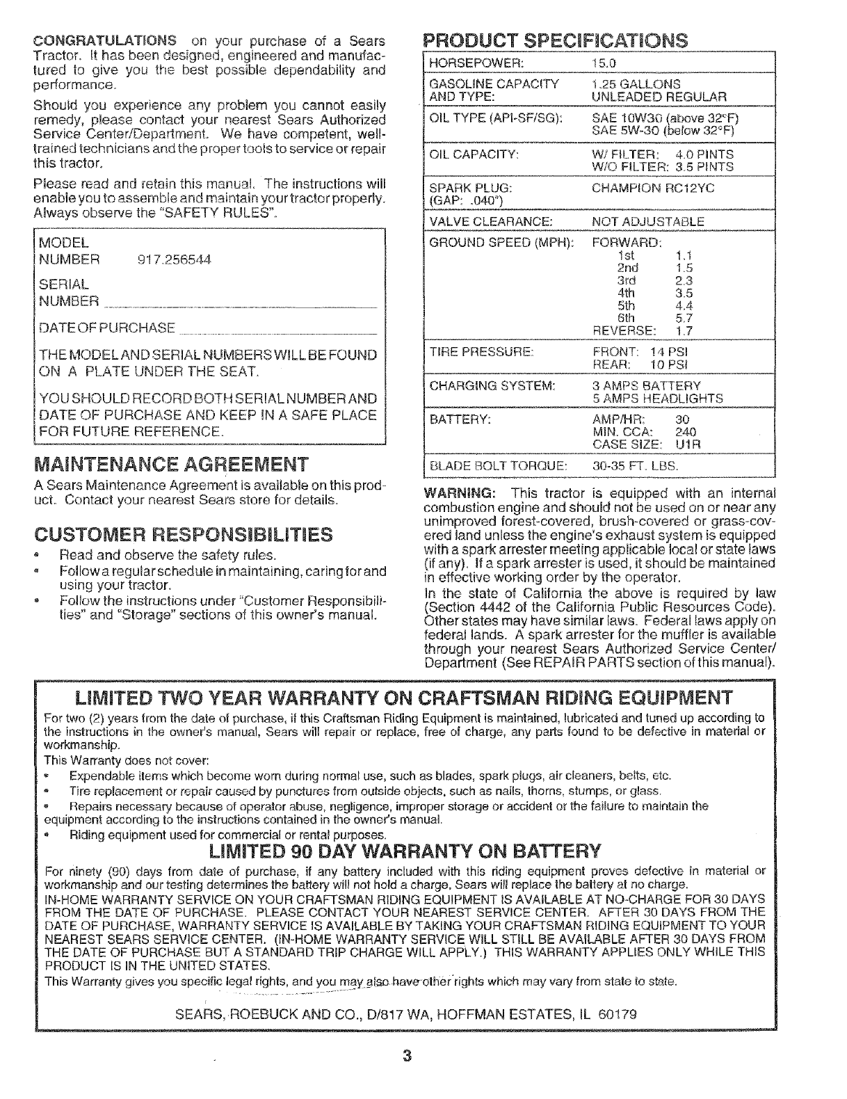
PRODUCT SPECIFmCATIONS
HORSEPOWER: 15.0
GASOLINE CAPACITY 1,25 GALLONS
AND TYPE: UNLEADED REGULAR
OIL TYPE (APFSF!SG): SAE 10W30 (above 32°E)
SAE 5W-30 (below 32°F)
OIL CAPACITY: W/FILTER: 4.0 HNTS
W!O FILTER: 3.5 P_NTS
SPARK PLUG: CHAMPION RC12YC
(GAP: ,040")
VALVE CLEARANCE: NO] ADJUSTABLE
GROUND SPEED (MPH): FORWARD:
1st 11
2nd 15
3rd 2_3
4th &5
5th 4_4
6th 5.7
REVERSE: 17
TIRE PRESSURE: FRONT: !4 PS!
REAR: t0 PSi
CHARGING SYSTEM: 3 AMPS BATTERY
5 AMPS HEADUGHTS
BATTERY: AMP/HR: 30
MIN. CCA: 240
CASE SIZE: U1R
BLADE BOLT TORQUE: 30-35 FT LBS.
WARNING: This tractor is equipped with an internal
combustion engine and should not be used on or near any
unimproved forest-covered, brush-covered or grass-cow
ered land unless the engine's exhaust system is equipped
with a spark arrester meeting applicable !ocal or state laws
(if any). If a spark arrester is used, it should be maintained
in effective working order by the operator.
In the state of California the above is required by law
(Section 4442 of the California Public Resources Code).
Other states may have similar laws. Federal laws apply on
federal lands. A spark arrester for the muffler is available
through your nearest Sears Authorized Service Center/
Department (See REPAIR PARTS section of this manual).
LIMITED TWO YEAR WARRANTY ON CRAFTSMAN RIDING EQUJPIVlENT
For two (2) years from the date ot purchase, it this Craftsman Riding Equipment is maintained, lubricated and tuned up according to
the instructions in the owneCs manual, Sears will repair or repmace,free of charge, any parts found to be defective in material or
workmanship.
This Warranty does not cover:
ExpendaMe items which become worn during normal use, such as blades, spark plugs, air cleaners, belts, etc.
Tire replacement or repair caused by punctures from outside objects, such as nails, thorns, stumps, or glass.
o Repairs necessary because of operator abuse, negligence, improper storage or accident or the faiBureto maintain lhe
equipment according to the instructions contained in the owner's manual
• Riding equipment used for commercial or rental purposes.
L MITED 90 DAY WARRANTY ON BATTERY
For ninety (90) days from date of purchase, if any battery included with this dding equipment proves defective in material or
workmanship and our testing determines the battery will not hold a charge, Sears will replace the battery at no charge.
IN-HOME WARRANTY SERVICE ON YOUR CRAFTSMAN RIDING EQUIPMENT iS AVAILABLE AT NO-CHARGE FOR 30 DAYS
FROM THE DATE OF PURCHASE. PLEASE CONTACT YOUR NEAREST SERVICE CENTER. AFTER 30 DAYS FROM THE
DATE OF PURCHASE, WARRANTY SERVICE IS AVAILABLE BY TAKING YOUR CRAFTSMAN RIDING EQUIPMENT TO YOUR
NEAREST SEARS SERVICE CENTER. (iN-HOME WARRANTY SERVICE WILL STILL BE AVAILABLE AFTER 30 DAYS FROM
THE DATE OF PURCHASE BUT A STANDARD TRIP CHARGE WILL APPLY.) THiS WARRANTY APPLIES ONLY WHILE THIS
PRODUCT IS IN THE UNITED STATES.
This Warranty gives you specific lega! rights, and you may_#Is_ hav_ otherrights which may vary from state to state.
SEARS ROEBUCK AND CO., D/817 WA, HOFFMAN ESTATES, IL 60179
3
TABLE OF CONTENTS
SAFETY RULES ............................................................ 2
PRODUCT SPEOSFICATIONS ...................................... 3
CUSTOMER RESPONSIBILITIES ..................... 3, 15-19
WARRANTY .................................................................. 3
TABLE OF CONTENTS ................................................. 4
ASSEMBLY ............................................................... 7-9
OPERATION .......................................................... 10-14
MAINTENANCE SCHEDULE ..................................... 15
SERVICE AND ADJUSTMENTS ........................... 20-25
STORAG E ................................................................... 26
TROUBLESHOOTING ........................................... 2"7-28
REPAIR PARTS ° TRACTOR ................................ 30=47
REPAIR PARTS -ENG|NE .................................... 48-53
PARTS ORDERING/SERVICE .................. BACK PAGE
INDEX
A
Accessories ...................... ..................... 5
Adjustments:
Brake .......................................... 22
Carburetor .................................. 25
Mower:
Front-To-Back ........................ 21
Side-To-Side .......................... 21
Throttle Controi Cable ................. 24
Air Filter. Engine ................................. 18
Air Screen, Engine ............................. 18
Assembly ........................................... 7-9
B
Battery:
Charging ....................................... 8
Cleaning ...................................... 17
Starting wilh Weak Battery .......... 23
Slorage ....................................... 26
Terminals .................................... 17
Belts:
Motion Drive
Removal/Replacement ........... 22
Mower B_ade Drive
Removal/Replacement ........... 22
Blade:
Sharpening .................................. 16
Replacement ............................... 16
Brake Adjustment ............................... 22
C
Carburetor Adjustment ...................... 25
Controls, Tractor ................................ 11
Customer Responsibilities ............ 15-19
Engine:
Air Filter ................................... 18
Air Screen, Engine .................. 18
Battery ..................................... 17
Cooling Fins, Engine ............... 18
Engine Oil ............................... 17
Fuel Filter ................................. 19
Spark Plugs ............................. 19
Tractor:
Blades ..................................... 16
Lubrication Chart ..................... 15
Maintenance Schedule ........... 15
Tire Care ......................... 9,16,23
Cutting Height, Mower ........................ 12
E
•Electrical:
'interlocks and Relays ................. 24
Schematic ................................... 29
Wiring Diagram ........................... 30
Engine:
Air Filter ...................................... 18
Air Screen .................................... 18
Cooling Fins, Engine ................... 18
Oi] Change ................................ 17
Oil Level ................................. 13,17
Oil Type ...................................... 17
Preparation ................................. 13
Repair Parts ........................... 48-53
Starting ....................................... 14
Storage ....................................... 28
F
Filters:
Air ................................................ 18
Fuel ............................................. 19
Fuel:
Type .......................................... 13
Storage ....................................... 26
Fuse ................................................... 24
G
Gauge Wheels ..................................... 9
N
Hood Removal!Installation ................. 24
L
Leveling Mower Deck ......................... 21
Lubrication Chart ................................ 15
M
Maintenance Schedule ...................... 15
Mower:
Adjustment, Front-to-Back .......... 21
Adjustment, Side-to-Side ............ 21
Blade Sharpening ....................... 16
Blade Replacement ..................... 16
Cutting Height ............................. 12
Installation ................................... 20
Operation .................................... 13
Removal ............... :...................... 20
Mowing Tips ....................................... 14
Muffler .:.............................................. 19
Spark Arrester .......................... 3,40
Mulcher Plate ....................................... 9
O
Oil:
Cold Weather Conditions ....... 13,17
Engine ......................................... 17
Storage ....................................... 26
Operation ...................................... 10-14
Operating Mower .............................. 13
Options:
Accessories ................................... 5
Spark Arrester .......................... 3,40
P
Parking Brake ............................... 11-12
Parts Bag ............................................. 6
Parts, Replacement/Repair ........... 30-47
Product Specilicatiens ........................... 3
R
Repair Parts .................................. 30-47
S
Safety Rules ........................................ 2
Seat ...................................................... 8
Service and Adjustments .............. 20-25
Brake .......................... ;............... 22
Carburetor .................................... 25
Fuse ............................................ 24
Hood Removal/Installation .......... 24
Motion Drive Belt
Removal/Replacement ........... 22
Mower Blade Drive Belt
Removal/Replacement ........... 22
Mower Adjustment:
Fronl-to-Back ......................... 21
Side-to-Side ........................... 21
Mower Installation ....................... 20
Mower Removal .......................... 20
Tire Care ............................. 9,16,23
Slope Guide Sheet ............................ 55
Spark Plugs ......................................... 19
Specifications ...................................... 3
Starting the Engine ....................... 13-14
Steering Wheel ............................... :7,23
Stopping the Tractor ........................... 12
Storage ............................................... 26
T
Throttle Control Cable Adjustment ..... 24
Tires .......................................... 9,16,23
Trouble Shooting Chart .................. 27-28
Transaxle Repair Parts ................. 46-47
W
Warranty ............................................... 3
Wiring Diagram ................................. 30
Wiring Schematic ............................... 29
4
ACCE D ATTACHMENTS
These accessories and atlachmer_to were available through most Sears retail outlets and service centers when the tractor was purchased_
Most Soars stores can order these items for you when you provide the modai number of your tractor.
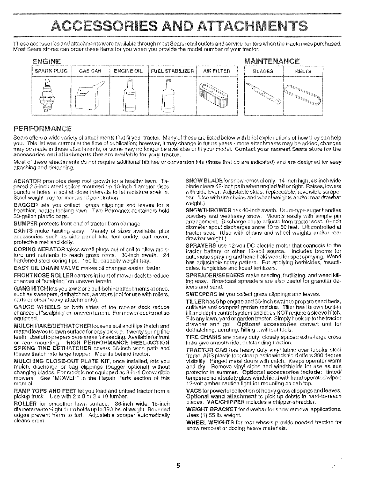
ENGINE
SPARK PLUG
MAINTENANCE
F
GAS CAN AiR FILTER BLA_3ES BELTS
PERFOR_ANCE
Sears offers a wde v:_,fiety of attac# monte that fit your tractor. Many of these are listed below with brief explanations of bow 1hay can hefp
you This list was cura::nt at the time of publication; however, it may change in future years- more attachments may be added, changes
may be made in these >_tachme.nts, or some may no longer be available or ti_your model Contact yot_r nearest Sears store for the
accessories and attachments that a_e ava_table for your tractor.
Most at these attachments de not require additiona! hitches or conversion kits (those that do are indicated} and are designed for easy
attaching arid detaching.
AERATOR promotes deep root growth for a healthy lawn Ta-
pered 2.5-inch steel spikes meur_fed on 10-inch diameter discs
puncture hales in soil at close intervals to !at moisture soak [n
Steel weight tray for incleased penetration
BAGGER _ets you collect grass cfippings and ieaves for a
hen!thief, nearer looking lawn. Two Permanex containers hold
30-gallon plastic bags
BUMPER protects front end of tractor from damage_
CARTS make hauling easy. Variety of sizes available, plus
accessories such as side panel kits, toot caddy, cad cover,
protective mat and dotty.
CORING AERATOR takes smatt plugs out of soil to allow mois-
ture and nutrients to reach grass roots. 36-inch swath. 24
hardened stee_ coring tips. 150 lb, capacity weight tray_
EASY OIL DRAIN VALVE makes oil changes easier, faster.
FRONT NOSE _OLLER canters in front of mower deck to reduce
chances o! "scalping' on uneven terrain.
GANG HmTCHlets you tow 2 or 3 pull-behind attachments at once,
such as sweepers, dethatchers, aerators (not for use with rollers,
cads or other heavy attachments)
GAUGE WHEELS on both sides of the mower deck reduce
chances of "scalping" on uneven terrain. For mower decks not so
equipped.
MULCH RAKF_JDETHATCHER loosens soil and flips thatch and
matted leaves to lawn surface for easy pickup. Twenty spring tine
teeth. Usefu! to prepare bare areas forseeding. Available for front
or rear mounting. H_GH PERFORMANCE REELoACT_ON
SPRING TINE DETHATCHER covers 36-inch wide path and
tosses thatch into large hopper Mounts behind tractor.
MULCH|NG CLOSE-OUT PLATE KiT, once installed, lets you
mulch, discharge or bag clippings (bagger optional) without
changing biades. For models not equipped as 3-in-1 Convertible
mowers See 'MOWER" in the Repair Pads section of this
manual
RAMP TOPS AND FEET let you load and unload tractor from a
pickup truck. Use with 2 x 8 or 2 x 10 _umber.
ROLLER for smoother lawn surface. 36-inch wide, 18-inch
diameter water-tight drum holds up to 390 Ibs, of weight. Rounded
edges prevent harm to tuff. Adiustable scraper automatically
cleans drum.
SNOW BLADE for snow _emo_ I only. t,4,-inch high, 48qnch wide
btade clears 42-inch path when angled ted or right Raises, bwers
with side ]ever, Adjustable skids; replaceable, reversible scraper
bar. (Use with tire chains and wheel weights and/or rear drawbar
weight,)
SNOWTNROWER has 40-inch swath Drum-type auger handles
powdery and weL_heavy snow. Mounts easily with simple pin
arrangement. Discharge chute adjusts from tractor seal 6qnch
diameter spout discharges snow 10 to 50 feet. Lift controlled at
tractor seat. (Use with chains and wheel weights and!or rear
drawbar weighL)
SPRAYERS use t 2-volt DO electric motor that connects to the
tractor battery or other 12-volt source. Includes booms for
automatic spraying and hand held wand for spot spraying. Wand
has adjustab e sp'ray pattern. For applying,, berbicides,_ insecti-
cides, fungicides and liquid fedilizers.
SPREADER/SEEDERS make seeding, fe_imizing, and weed kilF
ing easy. Broadcast spreaders are a!eo usefuJ for granular de-
icers and sand.
SWEEPERS let you collect grass clippings and leaves.
TBLLER has 5 hp engine and 36-inch swath to prepare seed beds,
cultivate and compost garden residue. Tiller has its own bui_tqn
tilt and depth control system and does NOT require a sleeve hitch.
Fits any lawn, yard or garden tractor. Simply hook up to the tractor
drawbar and go! Optiona_ scceeeor_ea convert unit for
dethatching, aerating, hilling..owithout tools,
TiRE CHAINS are heavy duty; ciosdy spaced extraqarge cross
links give smooth ride, outstanding traction.
TRACTOR CAB has heavy duty vinyl fabric over tubular steel
frame, ABS plastic top; clear plastic windshield offers 360 degree
visibility. Hinged motet doors with catch, Keeps operator warm
and dry. Remove viny_ sides and windshields for use as sun
protector in summer. Optiona_ accessories include: tinted/
tempered solid safety glass windshield with hand operated wiper;
12-volt amber caution light for mounting on cab top
VACS for powedu_ collection of heavy grass clippings and leaves.
Opt_ona! wand attachment to pick up debris in hard4o-reach
places. VAO/OH_PPER includes a chipper-shredder_
WEIGHT BRACKET for drawbar for snow removal applications
Uses (t) 55 _b_weight
WHEEL WEIGHTS for rear wheels provide needed traction for
snow removal or dozing heavy materials.
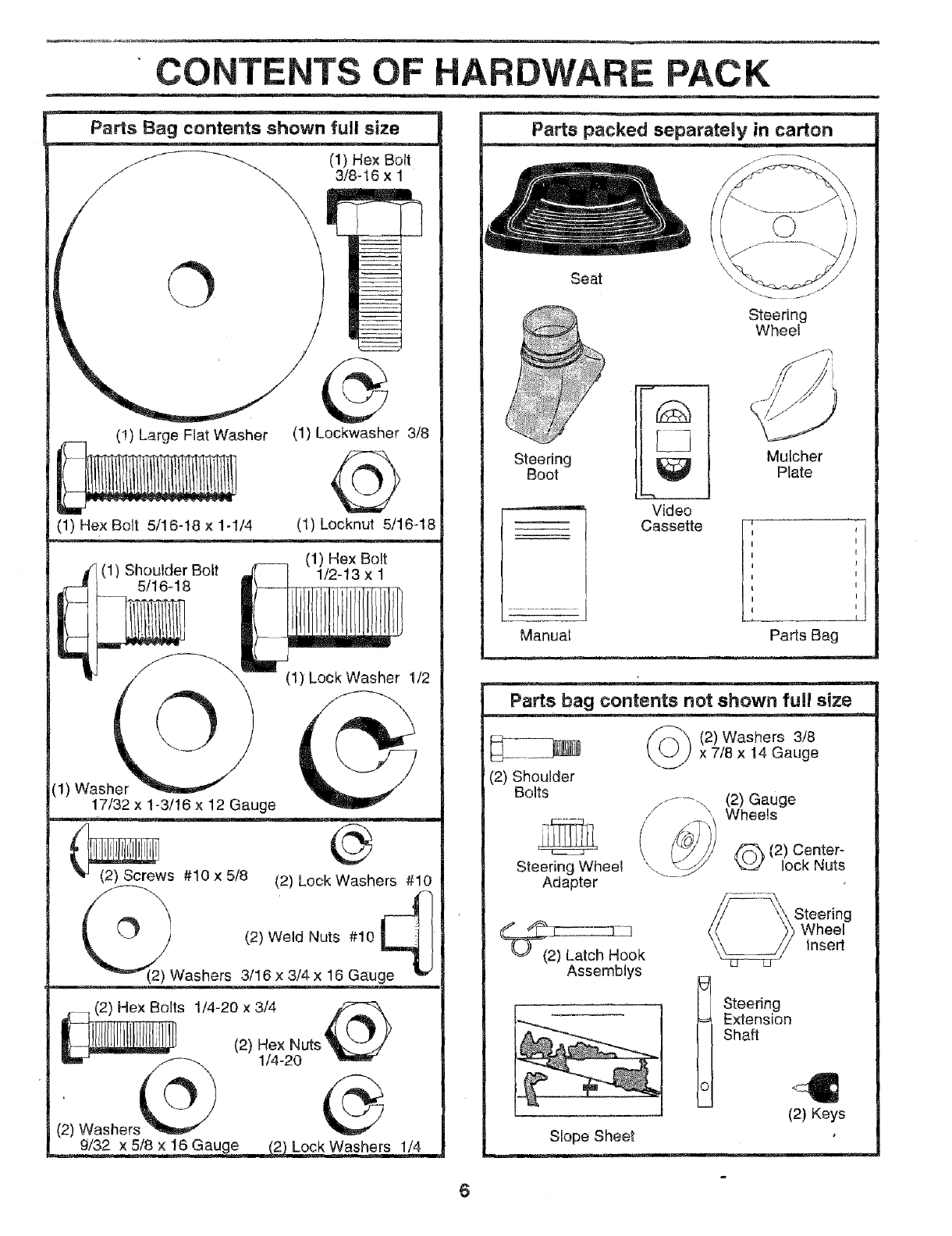
CONTENTS OF HARDWARE. PACK
Parts Bag contents shown full size
(1) Hex Bolt
3/8-16 x 1
\
O
(!) Large Flat Washer (1) Leckwasher 3/8
(1) Hex Bolt 5/16-18 x 1-1/4 (1) Locknut 5/18-18
(1) Hex Bolt
__ (1) Shoulder Bolt 1/2-13 x 1
5/16-18
"! ©(1) Lock Washer 112
(!) Washer
17/32 x 1-3/16 x 12 Gauge
(2) Screws #10 x 5/8 (2) Lock Washers #10
q
O (2) Weld Nuts #10
Washers 3/16 x 3/4 x 16 Gnu
(2) Washer.,
__ockWashe rs !/4
Seat
Steering
Wheel
Steering
Boot
Manuai
Video
Cassette
Mulcher
Plate
II
I I
I I
II
tI
II
I I
Parts Bag
Parts bag contents not shown full size
(2) Washers 3/8
x 7/8 x 14 Gauge
.........- (2) Gauge
/Wheels
_ (2) Center-
lock Nuts
Steering Wheel
Adapter
(2) Shoulder
Bolts
Assemblys
(2) Keys
Slope Sheet
6
LY
Your new tractor has been assembled at the factory with exception of those parts left unassembied for _-'..-,h_ppmg°," . #urp _...__" ,o_ ......
To ensure safe and proper operation of your tractor a]t parts and hardware you assernbte must be tightened securely. Use
the correct tools as necessary to insure proper tightness
TOOLS REQUIRED FOR ASSEMBLY
A socket wrench set will make assembly easier Standard
wrench sizes are listed.
(1) 5/16" wrench
(2) 7/16" wrenches
(f) 1/2" wrench
(1) 9/!6" wrench
(1) 3/4" Socket w/drive rachet
Philiips Screwdriver
Tire pressure gauge
Utility knife
When right or left hand is mentioned in this manual, it
moans when you are in the operating position (seated
behind the steering wheel)
TO REMOVE TRACTOR FROM CARTON
UNPACK CARTON
, Remove all accessible loose paris and parts cartons
from carton (See page 6).
oCut, from top to bottom, _'donglines on all four corners
of carton, and lay panels fiat.
o Check for any additional loose parts or cartons and
remove.
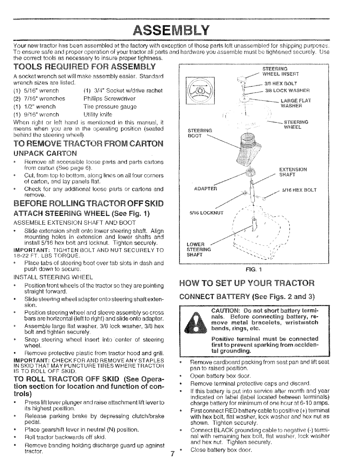
BEFORE ROLLING TRACTOR OFF SKID
ATTACH STEERING WHEEL (See Fig, 1)
ASSEMBLE EXTENSION SHAFT AND BOOT
, Slide extension shaft onto lower steering shaft. Align
mounting holes in extension and lower shafts and
install 5/16 hex bolt and Iocknut. Tighten securely.
IMPORTANT: TIGHTEN BOLT AND NUT SECURELY TO
18-22 FT. LBS TORQUE_
Place tabs of steering boot ever tab slots in dash and
push down to secure.
INSTALL STEERING WHEEL
o Position front wheels of the tractor so they are pointing
straight fonNard_
• Slide steering wheel adapter onto steering shaft exten-
sion.
Position steering wheel and sleeve assembly so cross
bars are horizontal (left to right) and slide onto adapter.
Assemble large fiat washer, 3/8 lock washer, 3/8 hex
bolt and tighten securely,
Snap steering wheel insert into center of steering
wheel
• Remove protective plastic from tractor hood and grill.
IMPORTANT: CHECK FOR AND REMOVE ANY STAPLES
11'4SKID THAT MAY PUNCTURE TmRESWHERE TRACTOR
Is TO ROLL OFF SKID.
TO ROLL TRACTOR OFF SKID (See Opera-
tion section for moeation and function of con-
trols)
• Press lift iever plunger and raise attachment lift lever to
its highest position.
o Release parking brake by depressing clutch/brake
pedal.
= Place gearshift lever in neutral (N) position.
• Roll tractor backwards off skid.
• Remove banding holding discharge guard up against
tractor.
STEERING
/WHEEL INSERT
t_'3'_,-)/I ' __3r_LockWAS.ER
-----,:.=: ........... ,. ,r ........... LARGE FLA]
i WASHER
j,( /
WHEEL
STEERING
BOOT
EXTENSION
SHAFT
ADAPTER 5f16 HEX BOLl
5/16 LOCKNUT
LOWER
STEERmNG
SHAFT
FIG. 1
HOW TO SET UP YOUR TRACTOR
CONNECT BATTERY (See Figs. 2 and 3}
CAUTION: Do not short battery termi-
nals_ Before connecting battery, re-
move meta_ bracelets, wristwa[ch
bands, rings, etco
Positive terrBir_al must b_ connected
first to prevent sparkiag from acciden-
tal grounding.
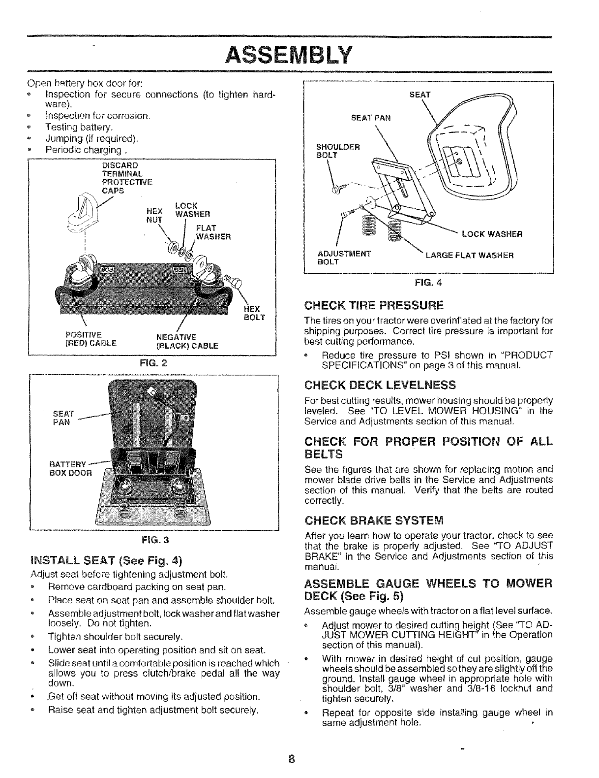
o Remove cardboard packing from seat pan and lift seat
pan to raised position.
• Open battery box door
, Remove terminal protective caps and discard.
- If this battery is put into service after month and year
indicated on label (label !ocated beh,_een terminals)
charge batten/for minimum of one hour at 6-10 amps.
oFirst connect RED battery cable to positive (+) terminal
with hex bolt, flat washer, lock washer and hex nut as
shown. Tighten securely.
, Connect BLACK grounding cable to negative (-) termi-
nal with remaining hex bolt, fiat washer, !ock washer
and hex nut. Tighten securelyo
o Close battery box door.
ASSE LY
Open battery box door for:
o Inspection for secure connections (to tighten hard-
ware).
mnspection for corrosion.
,, Testing battery.
Jumping (if required).
Periodic charging
DISCARD
TERMmNAL
PROTECTIVE
CAPS
POSITIVE
(REDt CABLE
LOCK
HEX WASHER
NUT FLAT
WASHER
NEGATIVE
(BLACK) CABLE
HEX
BOLT
SEAT
PAN
FiG. 2
FIG. 3
INSTALL SEAT (See Fig° 4)
Adjust seat before tightening adjustment bolt
, Remove cardboard packing on seat pan.
• Place seat on seat pan and assemble shoulder bolt.
,AssemMe adjustment bolt, Iockwasher and flat washer
loosely° Do not tighten.
Tighten shoulder bolt securely.
Lower seat into operating position and sit on seat.
o Slide seat until a comfortable position is reached which
allows you to press clutch/brake pedal all the way
down.
, ,Get off seat without moving its adjusted position.
Raise seat and tighten adjustment bolt securely.
SEAT
\ tt!
\
_LOCK WASHER
ADJUBTMENT " LARGE FLAT WASHER
BOLT
FIG, 4
CHECK TIRE PRESSURE
The tires on your tractor were overinflated at the factory for
shipping purposes. Correct tire pressure is important for
best cutting performance.
o Reduce tire pressure to PSI shown in "PRODUCT
SPECIFICATIONS" on page 3 of this manual.
CHECK DECK LEVELNESS
For best cutting results, mower housing should be properly
leveled. See "TO LEVEL MOWER HOUSING" in the
Service and Adjustments section of this manual.
CHECK FOR PROPER POSITION OF ALL
BELTS
See the figures that are shown for replacing motion and
mower blade drive belts in the Service and Adjustments
section of this manual. Verify that the belts are routed
correctly.
CHECK BRAKE SYSTEM
After you learn how to operate your tractor, check to see
that the brake is properly adjusted. See "TO ADJUST
BRAKE" in the Service and Adjustments section of this
manuai.
ASSEMBLE GAUGE WHEELS TO MOWER
DECK (See Fig. 5)
Assemble gauge wheels with tractor on a flat level sudace.
Adjust mower to desired cutting height (See "TO AD-
JUST MOWER CUTTING HEIGHT" in the Operation
section of this manual).
. With mower in desired height of cut position, gauge
wheels should be assembled so they are slightly off the
ground. Install gauge wheel in appropriate hole with
shoulder bolt, 3/8" washer and 3/8-16 Iocknut and
tighten securely°
Repeat for opposite side installing gauge wheel in
same adjustment hole. ,
E LY
FiG. 5
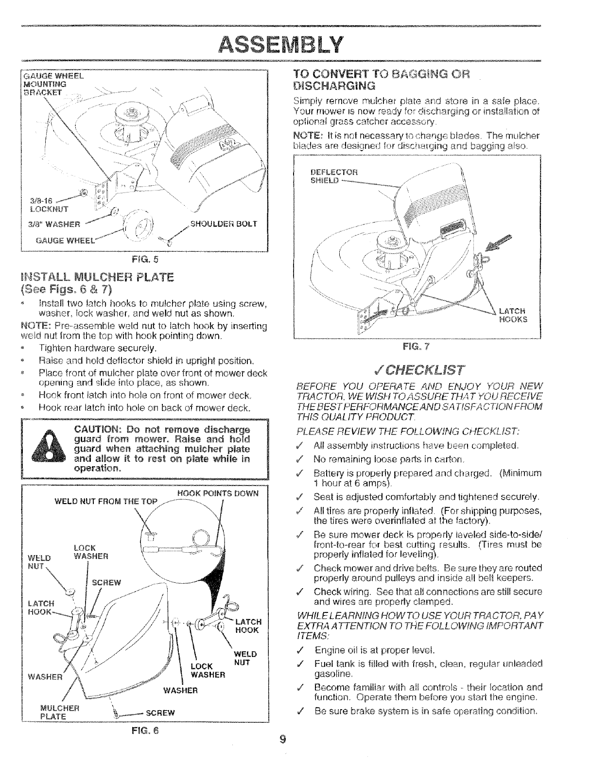
_NSTALL MULCHER PLf4TE
(See Figs. 6 & 7}
install two !arch hooks to mulcher plate using screw,
washer, bck washer_ and weld nut as shown.
NOTE: Pre-assembte weld nut to latch hook by inserting
weld nut from the top with hook pointing down.
o Tighten hardware securely.
o Raise and hold deflector shield in upright position
Place front of mulcher plate over front of mower deck
opening and slide in!o place, as shown.
o Hook front latch into hole on front of mower deck.
o Hook rear latch into hole on back of mower deck.
CAUTION: Do not remove discharge q
guard from mower. Raise and ham
guard when attaching muncher plate
,and alUow it to rest ca plate whiJe in |
ape
WELD
WASHER
MULCHER
PLATE
LOCK
WASHER
WELD
NUT
TO CONVERT TO B_,_G_NG OR
O_SCNARGiNG
Simpiy remove mulcher ptate ard store in a saie p_ace.
Your mower is now ready fo; discharging or insta!tation ,of
opfionaJ grass catcher accessory.
NOTE: It is not necessary to change blades The mulcher
btades are designed for discharging and bagging a_so.
DEFLECTOR ....
/s
(
x\
LATCN
H©OKS
F_G,7
BEFORE YOU OPERATE AND ENJOY Y@UR NEW
TRACTOR, WE WISH TOA.SSURE TH4 T YOU RECEIVE
THE BESTPERFOF4MANCEAND SA TfSFA CTION FROM
THIS OUALITY PRODUCT_
PLEASE REVIEW THE FOLL OWffVG CHECKLIST}
d' AI_assembly instructions have be÷n completed.
v" No remaining loose parts in ca4on
/Battery is properly prepared and charged (Minimum
1 hour at 6 amps).
v' Seat is adjusted comfortably and tightened securely.
v' Alltires are properly inflated (For shipping purposes,
the tires were overinflaled at 1he factory)
¢" Be sure mower deck is properly leveled side-to-side/
ffont4o-rear for best cutting rssuffs. (Tires must be
propedy inflated for beveling}
/Check mower and drive belts. Be sure they are routed
properly around pulleys and inside a!Jbe_t keepers.
,/ Check wiring. See that alJconnections are still secure
and wires are properly clamped.
WHILE LEARNING HOWTO USE YOUR TRACTOR, PAY
EXTRA ATTENTION TO THE FOLLOWING IMPORTANT
ITEMS:
¢' Engine oil is at proper _eveL
/Fuel tank is filled with fresh, c_ean, regular unleaded
gasoline.
v" Become familiar with all controls - their location and
function. Operate them before you star the engine_
/Be sure brake system is in safe operating condition.
FIG 6 9
OPERATION
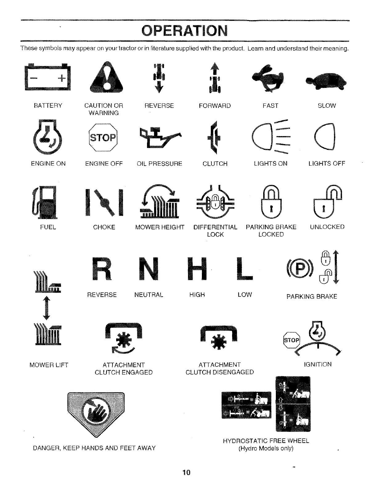
These symboJs may appear on your tractor or in literature supplied with the product. Learn and understand their meaning.
4_ t
BATTERY CAUTION OR REVERSE FORWARD FAST SLOW
WARNING
ENGINE ON ENGINE OFF OIL PRESSURE CLUTCH LIGHTS ON LIGHTS OFF
FUEL CHOKE
m-@
MOWER HEIGHT DIFFERENTIAL PARKING BRAKE UNLOCKED
LOCK LOCKED
!
MOWER LIFT
REVERSE NEUTRAL
ATTACHMENT
CLUTCH ENGAGED
L
HIGH LOW
ATTACHMENT
CLUTCH DISENGAGED
PARKING BRAKE
iGNITION
DANGER, KEEP HANDS AND FEET AWAY
HYDROSTATIC FREE WHEEL
(Hydro Models only)
10
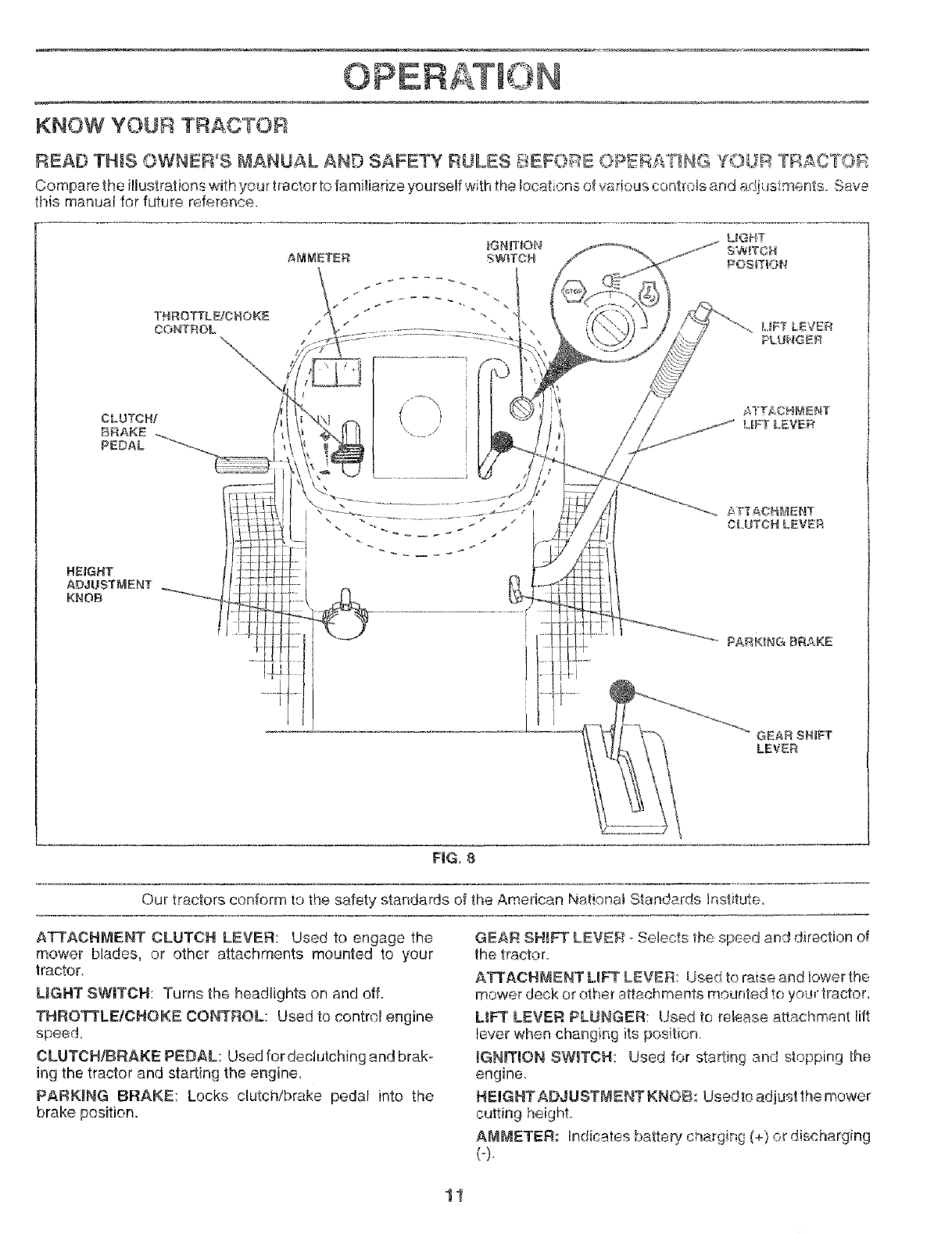
KNOW YOUR TRACTOR
READ THIS OWNER'S bIANUAL AND SAFETY RULES _:J_EFOR:BOPERATING YOUR TRACT'©_R
Compa re the illustrations with your tractor to famfRiarizeyourself with the !ocat ons of wMous conbels and adj .ts_ments. Save
this manual for future reference.
THROTTLEICHOKE
OONTBOL
\/
i
FiG, 8
r_tu )r18[
Our tractors conform to the safety standards of the American ,,_.ic °' Standerds hstitute_
ATTACHMENT CLUTCH LEVER: Used to engage the
mower blades, or other attachments mounted to your
Iractor
LIGHT SWITCH: Turns the headlights on and off.
THROTTLE/CNOKE CONTROL: Used to control engine
speed,
CLUTCH/BRAKE PEDAL: Used fordeclutching and brak-
ing the tractor and starting the engine.
PARKING BRAKE: Locks clutch/brake pedal into the
brake position.
GEAR SHIFT LEVER - Selects the speed and direction of
the tractor.
ATI'ACRB_ENT LIF _LEVER: Used to raise and bwer the
mower deck or other attachments mounted to your tractor.
L!_ LEVER PLUNGER: Used to release attachment lift
lever when changing its position
UGN_TION SW_TCH: Used for starting and stopping the
engine_
HEIGHT ADJUSTMENT KNOB: Used_o adjust the mower
cutting height.
AMMETER: Indicates batteq/charging (+) or discharging
(-).
11
..... i, OPERATIC
_can r
js_,_G__n severe ey edamage. Always wear safety __hile operating your J
I tractor or performing any adjustments o_sion safety mask
[ over the spectacles or standard safety glass.. ..............
HOW TO USE YOUR TRACTOR
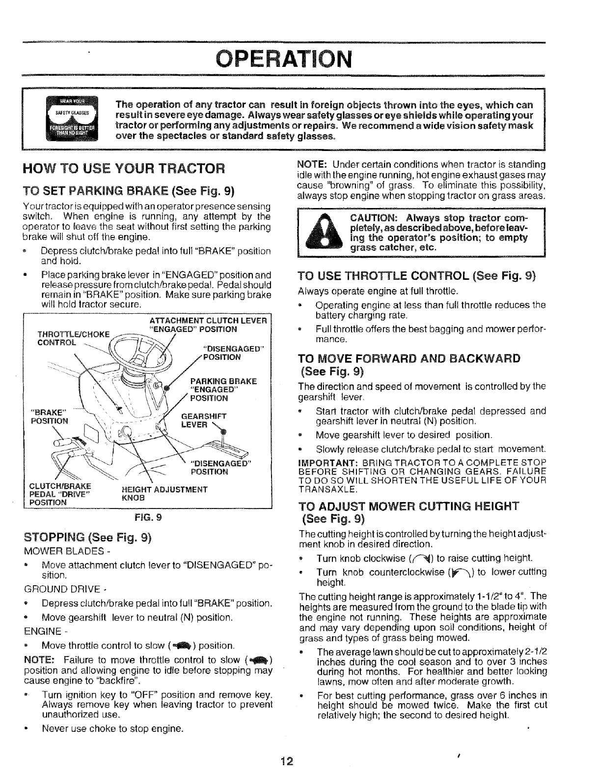
TO SET PARKING BRAKE (See Fig. 9)
Your tractor isequipped with an operator presence sensing
switch. When engine is running, any attempt by the
operator to leave the seat without first setting the parking
brake wil! shut off the engine.
oDepress dutch/brake pedal into full "BRAKE" position
and hold.
Place parking brake lever in "ENGAGED" position and
release pressure from clutch/brake pedal. Pedal should
remain in"BRAKE" position. Make sure parking brake
will hold tractor secure.
THROTTL_CHOKE
CONTROL
ATTACHMENT CLUTCH LEVER
"ENGAGED"POSITION
"BRAKE" GEARSHIFT
POSITION
"DISENGAGED"
POSITION
CLUTCH/BRAKE HEIGHT ADJUSTMENT
PEDAL "DRIVE" KNOB
POSmON
FIG. 9
STOPPING (See Fig. 9)
MOWER BLADES -
"Move attachment clutch lever to "DISENGAGED" po-
sition.
GROUND DRIVE -
Depress clutch/brake pedal intofull "BRAKE" position.
o Move gearshift lever to neutral (N) position.
ENGINE -
,Move throttle control to slow (,II,) position.
NOTE: Failure to move throttle control to slow (_)
position and allowing engine to idle before stopping may
cause engine to "backfire",
,, Turn ignition key to "OFF" position and remove key,
Always remove key when leaving tractor to prevent
unauthorized use,
-Never use choke to stop engine,
NOTE: Under certain conditions when tractor is standing
idle with the engine running, hot engine exhaust gases may
cause "browning" of grass. To eliminate this possibility,
always stop engine when stopping tractor on grass areas.
TO USE THROTTLE CONTROL (See Fig. 9)
Always operate engine at full throttle,
•Operating engine at less than full throttle reduces the
battery charging rate.
Full throttle offers the best bagging and mower perfor-
mance.
TO MOVE FORWARD AND BACKWARD
(See Fig. 9)
The direction and speed of movement is controlled by the
gearshift lever.
-Start tractor with clutcb,/brake pedal depressed and
gearshift lever in neutral (N) position.
-Move gearshift lever to desired posilion.
Slowly release clutch/brake pedal to start movement.
IMPORTANT: BRING TRACTOR TO A COMPLETE STOP
BEFORE SHIFTING OR CHANGING GEARS. FAILURE
TO DO SO WILL SHORTEN THE USEFUL LIFE OF YOUR
TRANSAXLE.
TO ADJUST MOWER CUTTING HEIGHT
(See Fig. 9)
The cutting height is controlled byturning the height adjust-
ment knob in desired direction.
Turn knob clockwise (f_) to raise cutting height.
•Turn knob counterclockwise (_#-_) to lower cutting
height.
The cutting height range is approximately 1-1/2" to 4". The
heights are measured from the ground to the blade tip with
the engine not running. These heights are approximate
and may vary, depending upon soil conditions, height of
grass and types of grass being mowed.
.The average lawn should be cut to approximately 2-1/2
inches during the cool season and to over 3 inches
during hot months. For healthier and better looking
lawns, mow often and after moderate growth.
.For best cu_ing performance, grass over 6 inches in
height should be mowed twice. Make the first cut
relatively high; the second to desired height.
12
0ON
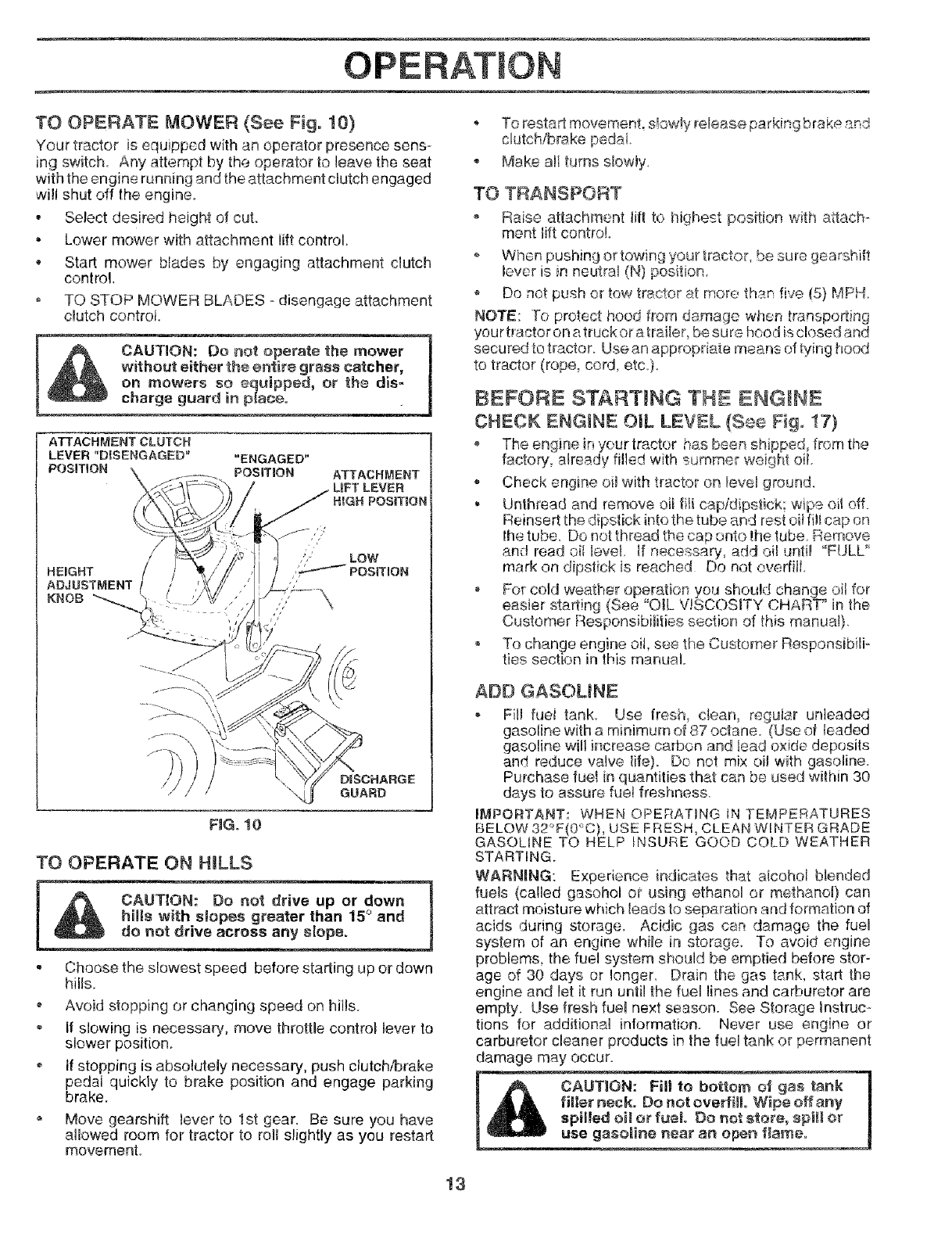
TO OPERATE MOWER (See Fig. 10)
Your tractor is equipped with an operator presence sens-
ing switch, Any attempt by the operator to leave the seat
with the engine running and the attachment clutch engaged
will shut off the engine.
• Select desired height of cut,
• Lower mower with attachment lift control.
* Start mower blades by engaging attachment clutch
control,
o TO STOP MOWER BLADES - disengage attachment
clutch control.
charge- guard m piece, j
ATTACHMENT
LIFT LEVER
HIGH POSmON
HEIGHT
ADJUSTMENT
}(NOB
DISCHARGE
GUARD
FiG. 10
TO OPERATE ON HmLLS
hil_ wi_rea_han 15° and [
• Choose the slowest speed before starting up or down
His.
, Avoid stopping or changing speed on hills.
If slowing is necessary, move throttle control lever to
slower position.
° tf stopping is abso!utely necessary, push clutch/brake
pedal quickly to brake position and engage parking
brake.
Move gearshift lever to 1st gear. Be sure you have
allowed room for tractor to felt slightly as you restart
movemenL
• To restart movemenL s_ow!yreleas#_ parkir_gbrake _nd
clutch/brake pedai.
, Make eli turns slowty,
TO TRANSPORT
o Raise attachment flit to l]ighest position with attach-
ment lift controi.
- When pushing or towing your tractor, be sure gearshift
lever is in neutral (N) position
Do not push or tow tractor at more than five (5) MPH,
NOTE: -To protect hoed from damage when transporting
your hector on atruckor atraiier, be sure hood is closed and
secured to tractor,. Use an appropriate means of tying hood
to tractor (rope, cord, etc,).
BEFORE STARTING THE ENGINE
CHECK ENGINE OIL LEVEL (See Fig. !7)
, The engine in your tractor has been shipped, frem the
factory already filled with summer weight oil,
- Check engine oil with tractor on Ievet ground.
• Unthread and remove oil flit cap/dipstick; wipe oi_off.
Reinsert the dipstick into the tube and rest oil fill cap on
the tube. Do not thread the cap onto the tube. Remove
and read oil level, if necessary, add oi! until "FULL"
mark on dipstick is reached Do not eveditl,
- For cold weather operation you should chanqe oil for
easier starting (See "OIL V!SCOSITY CHAR_F* in the
Customer Responsibilities section of this manual},
, To change engine oil, see the Custon-_er Responsibilio
ties sec(Lon in this manual,
ADD GASOUNE
- Fill fuei tank Use fresh_ dean, reguiar unleaded
gasoline with a minimum of 87 octane, (Use of leaded
gasoline will increase carbon and lead oxide deposits
and reduce valve life) Do not mix oi! with gasoline
Purchase fuel in quantities that can be used wilhin 30
days to assure fuel freshness.
IMPORTANT: WHEN OPERATING IN TEMPERATURES
BELOW 32°F(0'--C), USE FRESH, CLEAN WINTER GRADE
GASOUNE TO HELP INSURE GOOD COLD WEATHER
STARTING.
WARNING: Experience indicates that alcohol blended
fuels (called gasohol or using ethanol or methanol) can
attract moisture which leads to separation and formation of
acids during storage. Acidic gas can damage the fuel
system of an engine while in storage. To avoid engine
problems, the fuel system should be emptied before stor-
age of 30 days or longer. Drain the gas tank, start the
engine and let it run until the fuel lines and carburetor are
empty. Use fresh fuel next season. See Storage Instruc-
tions for additional information. Never use engine or
carburetor cleaner products in the fue! tank or permanent
damage may occur.
13
OP
TO START ENGINE (See Fig. 9}
When starting the engine for the first time or if the engine
has run out of fuel, it wil_ take extra cranking time to move
fuel from the tank to the engine.
*Depress clutch/brake pedal and set parking brake.
Place gear shift lever in neutral (N) position.
*Move attachment clutch to "DBENGAGED" position.
, Move throttle control to choke (IXI) position.
Note: Before starting, read the warm and cold starting
procedures below.
° Insert key into ignition and turn key clockwise to "START"
position and release key as soon as engine starts. Do
not run starter continuously for more than fifteen sec-
onds per minute. If the engine does not start after
several attempts, move throttle control to fast (,f_)
position, wait a few minutes and try again. Ifengine still
does not start, move the throttle control back to the
choke (N) position and retry.
WARM WEATHER STARTING (50° F and above)
When engine starts, move the throttle control to the fast
(,f_) position.
,, The attachments and ground ddve can now be used. If
the engine does not accept the load, restart the engine
and allow it to warm up for one minute using the choke
as described above.
COLD WEATHER STARTING ( 50 ° F and below)
When engine starts, allow engineto run with thethrottle
conlrol in the choke (NI) position until the engine runs
roughly, then move thrott econtro to fast (,_) post on.
This may require an engine warm-up period from
several seconds to several minutes, depending on the
temperature,
The attachments can also be used during the engine
warm-up period.
NOTE: If at a high altitude (above 3000 feet) or in cold
temperatures (below 32 F) the carburetor fuel mixture may
need to be adjusted for best engine performance. See "TO
ADJUST CARBURETOR" in the Service and Adjustments
section of this manual.
MOWING TIPS
Tire chains cannot be used when the mower housing is
attached to tractor.
- Mower should be properly leveled for best mowing
peformance. See"TO LEVEL MOWER HOUSING" in
the Service and Adjustments section of this manual.
,, The left hand side of mower should be used for trim-
ming_
• Drive so that clippings are discharged onto the area
that has been cut. Have the cut area to the right of the
machine. This will result in a more even distribution of
clippings and more uniform cutting.
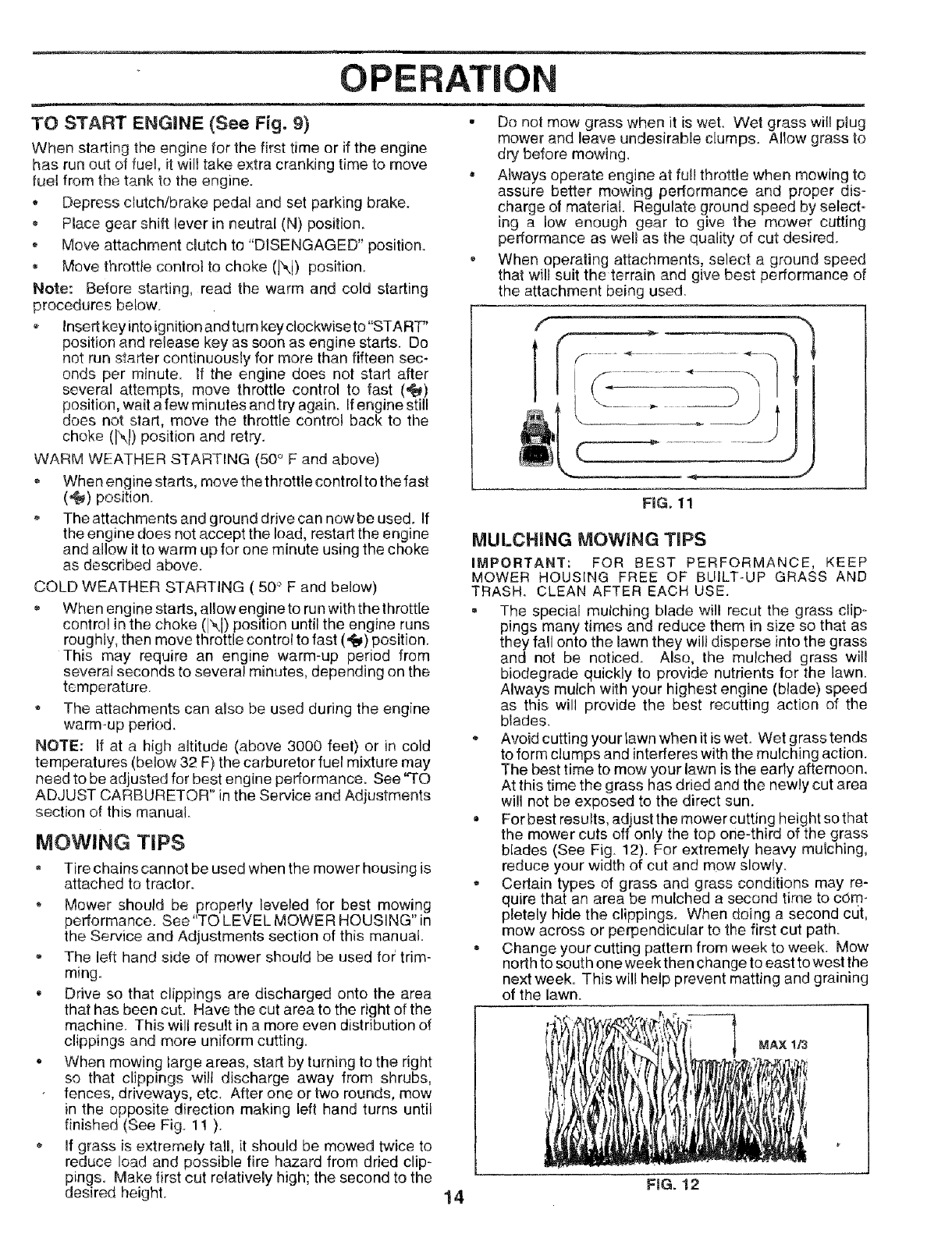
o When mowing large areas, start by turning to the right
so that clippings will discharge away from shrubs,
fences, driveways, etc. After one or two rounds, mow
in the opposite direction making left hand turns until
finished (See Fig. 11 ).
If grass is extremely tall, it should be mowed twice to
reduce load and possible fire hazard from dried clip-
pings. Make first cut relatively high; the second to the
desired height.
• Do not mow grass when it is wet. Wet grass will plug
mower and leave undesirable clumps. Allow grass to
dry before mowing,
• Always operate engine at full throttle when mowing to
assure better mowing performance and proper dis-
charge of material. Regulate ground speed by select-
ing a low enough gear to give the mower cutting
performance as well as the quality of cut desired,
o When operating attachments, select a ground speed
that will suit the terrain and give best performance of
the attachment being used.
FnG. 11
MULCHING tVIOWiNG TiPS
IMPORTANT: FOR BEST PERFORMANCE, KEEP
MOWER HOUSING FREE OF BUILT-UP GRASS AND
TRASH. CLEAN AFTER EACH USE.
, The special mulching blade will recur the grass clip-
pings many times and reduce them in size so that as
they fall onto the lawn they will disperse into the grass
and not be noticed. Also, the mulched grass will
biodegrade quickly to provide nutrients for the lawn.
Always mulch with your highest engine (blade) speed
as this will provide the best recutting action of the
blades.
* Avoid cutting your lawn when it is weL Wet grasstends
to form clumps and interferes with the mulching action.
The best time to mow your lawn is the early afternoon.
At this time the grass has dried and the newly cut area
will not be exposed to the direct sun.
For best results, adjust the mower cutting height so that
the mower cuts off only the top one-third of the grass
blades (See Fig. 12). For extremely heavy mulching,
reduce your width of cut and mow slowly.
- Certain types of grass and grass conditions may re-
quire that an area be mulched a second time to cdm-
pletely hide the clippings. When doing a second cut,
mow across or perpendicular to the first cut path
, Change your cutting pattern from week to week. Mow
north to south one week then change to east to west the
next week. This will help prevent matting and graining
of the lawn.
FIG. 12
14
ER FIESPON ES
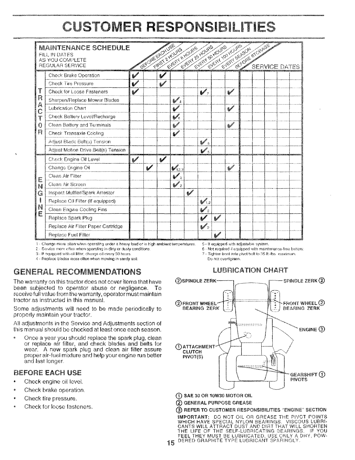
MAIHTENANCE SCHEDULE
FIL.I. IN D#7_ES
AS YOU COlvlPLEI"E
REGULAR SERVICE
Check Brake Operation
Check Tire Pressure
Check for Loose Fasteners
Sharpen/Replace Mower Blades
Lubrication Chart
Check Battery LeveVRecharge
Clean Battery and Terminals
Check Transa_le Cocling
Adjust Blads Be!t/s) Tension
Adjust Motion Drive Belt(s) Tension
C,_eck Engine Oil Level
Change Engine OIl
Clean Air Filter
Olearl Air Scnsen
Inspect MuffledSpark Arresler
R_place Oil Filter (If equipped)
Clean Engine Cooling Fins
Replace Spark PkJg
RepDace Air Fil_er Paper Cartridge
Replace Fuel Filter
- Change roor_ o[ter_ v_hen operating under a hea,_ (road or in high ambient temperatures.
[: Service rr_)re r ftei-_ when oper,_ting in dirty or dus_y conditions
3 - Ir equ pped ',_,ith ell [ir,_r, ch;_.rYje oil every 50 he_rs
4 - Replace b!ades more otten when mowing in sandy soil.
SERVICE DATES
5 - It equipped with adjustabie system+
6-Hot required f equipped witir maintel_anct_ffee barrel1,'
7. Tighten lront axle Fi,,mt bolt to :_5 fidbs nle__rimu_
Do not overtighten
GENERAL RECOMMENDATIONS
The warranty on this tractor does not cover items that have
been subjeded to operator abuse or negligence, To
receive full value from the warranty, operator must maintain
tractor as instructed in this manual
Some adjustments will need to be made periodically to
properly maintain your tractor.
All adjustments in the Service and Adjustments section of
this manual should be checked at least once each season.
Once a year you should reptace the spark plug, clean
or replace air filter, and check blades and belts for
wear, A new spark plug and clean air filter assure
proper air-fuel mixture and help your engine run better
and last longer,
LUBR+CATION CHART
;PJNDLE ZERK
@CLUTCH
PiVOT(S)
®
BEFORE EACH USE
• Check engine oJ(level
o Check brake operation
• Check tire pressure.
, Check for loose fasteners.
15
(_) SAE 30 OR 10W30 MOTOR OiL
{_) GENERAL PURPOSE GREASE
(_ REFER TO CUSTOMER FtESPONSIB_LmES "ENGINE" SECTION
IMPORTANT: DO NOT OIL OR GREASE THE P_VO'f POINTS
WHICH HAVE SPECIAL NYLON BEARINGS, VISCOUS LUBFH-
CANTS WILL ATTRACT DUST AND DtRT THAT WILL SHORTEN
_HE LIFE OF THE SELF-LUBRICAT!NG BEARINGS+ IF YOU
FEEL THEY MUST BE LUBRICATED, USE ©NLY A E)_4Y+POW-
DERED GRAPHITE TYPE LUBRIOAN't 3P#RINGLY.
m
CUSTO
TRACTOR
Always observe safety rules when performing any mainte-
nance.
BRAKE OPERATION
If tractor requires more than six (6) feet stopping distance
at high speed in highest gear, then brake must be adjusted.
(See "TO ADJUST BRAKE" in the Service and Adjust-
ments section of this manual).
TIRES
ILITIES
o Maintain proper air pressure in all tires (See "PROD-
UCT SPECIFICATIONS" on page 3 of this manual).
Keep tires free of gasoline, oil, or insect control chemi-
cals which can harm rubber.
Avoid stumps, stones, deep ruts, sharp objects and
other hazards that may cause tire damage.
BLADE CARE
For best results mower blades must be kept sharp. Re-
place bent or damaged blades.
BLADE REMOVAL (See Fig. 13)
•Raise mower to highest position to allow access to
blades.
o Remove hex bolt, lock washer and flat washer securing
blade.
• Install new or resharpened blade with trailing edge up
towards deck as shown.
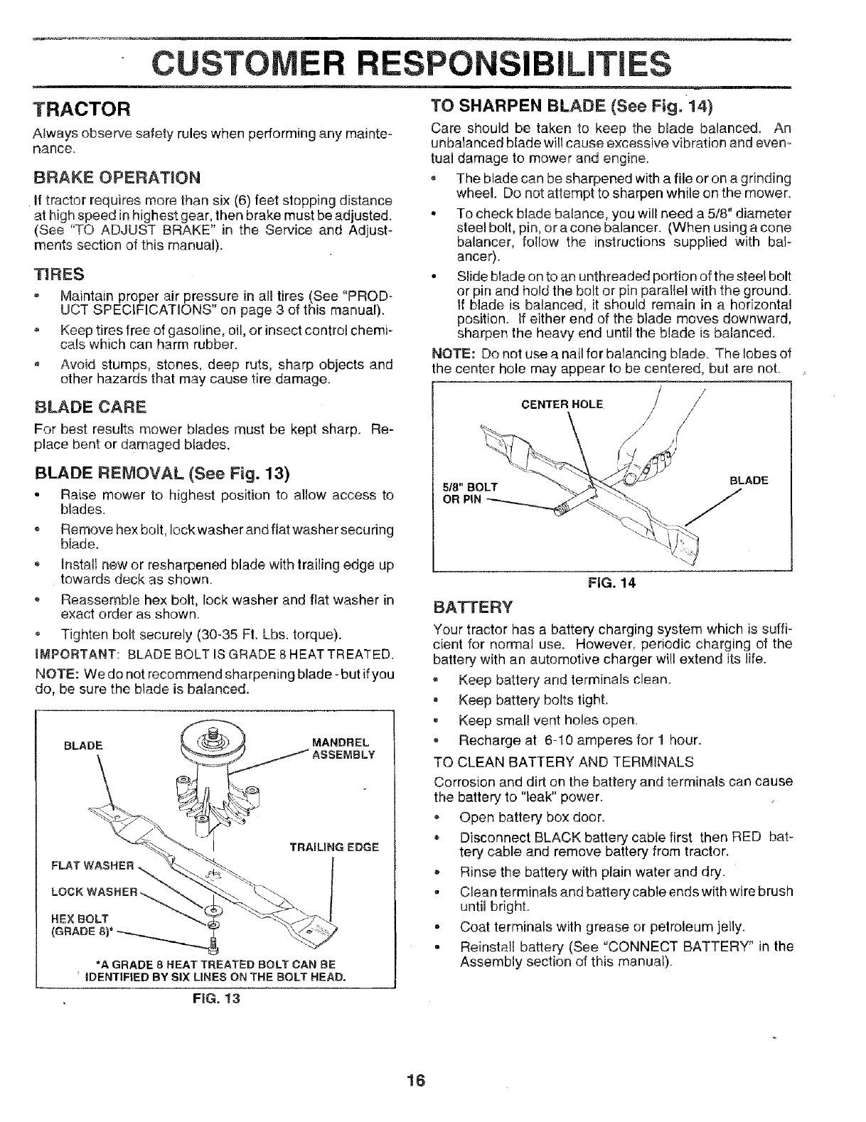
TO SHARPEN BLADE (See Fig. 14}
Care should be taken to keep the blade balanced. An
unbalanced blade wilt cause excessive vibration and even=
tual damage to mower and engine.
The blade can be sharpened with a file or on a grinding
wheel. Do not attempt to sharpen while on the mower.
• To check blade balance, you will need a 5/8" diameter
steel bolt, pin, or a cone balancer. (When using a cone
balancer, fo!low the instructions supplied with bal-
ance0.
. Slide blade on to an unthreaded portion of the steel bolt
or pin and hold the bolt or pin parallel wilh the ground.
If blade is balanced, it should remain in a horizontal
position. If either end of the blade moves downward,
sharpen the heavy end until the blade is balanced.
NOTE: Do not use a nail for balandng blade. The lobes of
the center hole may appear to be centered, but are not.
Reassemble hex bolt, lock washer and flat washer in
exact order as shown.
Tighten bolt securely (30-35 Ft. Lbs. torque).
IMPORTANT: BLADE BOLT IS GRADE 8 HEAT TREATED.
NOTE: We do not recommend sharpening blade -but if you
do, be sure the blade is balanced.
BLADE MANDREL
TRAILING EDGE
CENTER HOLE / //
z
/
ji
BATTERY
FIG. 14
HEXBOLT
*AGRADE8HEATTREATED BOLTCAN BE
_IDENTIFIED BYSIXLINES ONTHE BOLT HEAD,
FiG. !3
Your tractor has a battery charging system which is suffi-
cient for normal use. However, periodic charging of the
battery with an automotive charger will extend its life.
,, Keep battery and terminals clean.
Keep battery bolts light.
• Keep smal} vent holes open.
Recharge at 6-10 amperes for 1 hour.
TQ CLEAN BATTERY AND TERMINALS
Corrosion and dirt on the battery and terminals can cause
the battery to "leak" power.
Open battery box door.
Disconnect BLACK battery cable first then RED bat-
tery cable and remove battery from tractor.
Rinse the battery with plain water and dry.
- Clean terminals and battery cable ends with wire brush
until bright.
. Coat terminals with grease or pelroleum jelly.
• Reinstal! battery (See "CONNECT BATTERY" in the
Assembly section of this manual).
16
RESPO
V-BELTS
Check V,belts for deterioration and wear after 100 hours of
operation and replace if necessary The belts are not
adjustable. Replace belts if they begin to slip from wear.
TRANSAXLE COOUNG
Keep tmnsax[e free from build-up of dirt and chaff which
can restrict cooling.
ENGINE
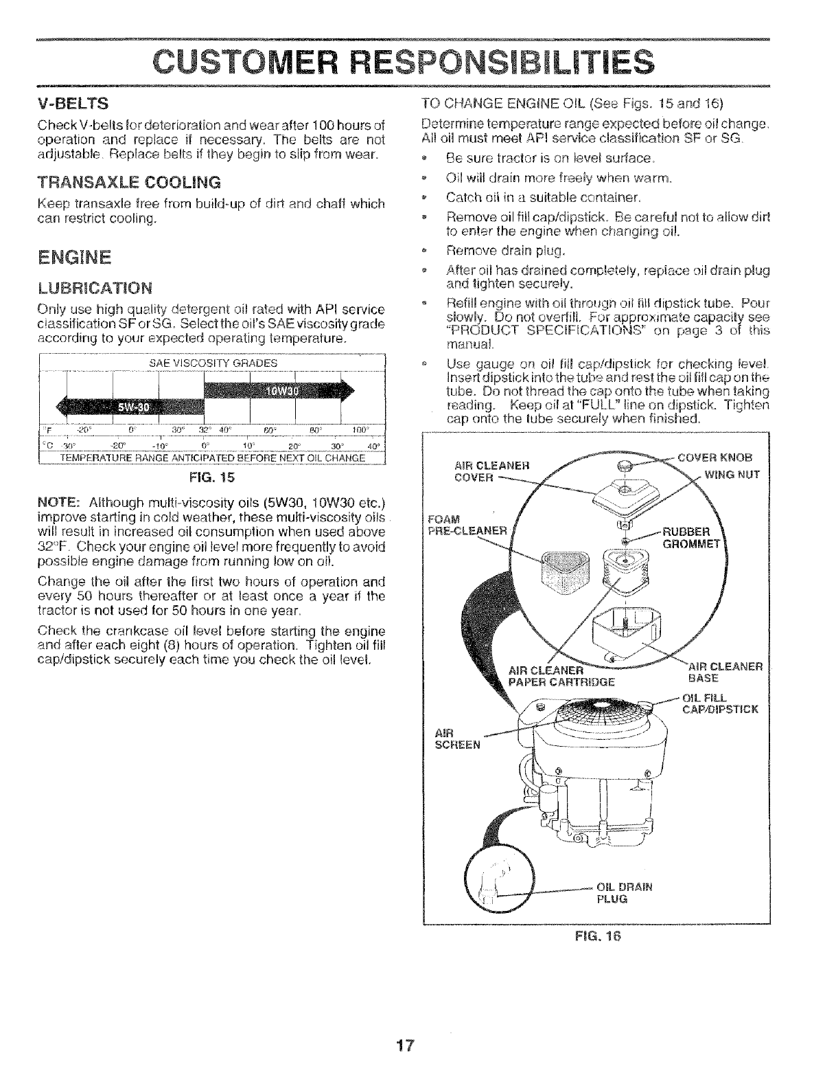
LUBRICATION
Only use high quality' detergent oil rated with API service
ciassification SF or SG Select the oil's SAE viscosity grade
according to your expected operating temperature.
SAE ViSCOSiTY GRADES
F -20" 0 30 _ 32" 40 ° f2-9_ 80 f00 _
c: _oZ............"_29"__..-_o'..........J!°...............!.°'_............__0+_ ..........._9_.............4oE_
TEMPERA'IURE RANGE ANTICIPATED BEFORE NEXT OIL CHANGE
FIG, !5
NOTE: Although multi-viscosity oils (5W30, 10W30 etc.)
improve starting in cold weather, these multi-viscosity oils
will result in increased oil consumption when used above
32°F. Check your engine oil level more frequently to avoid
possible engine damage from running low on oi!.
Change the oil after the Iirst two hours of operation and
every 50 hours thereafter or at least once a year if the
tractor is not used for 50 hours in one year.
Check the crankcase oil I÷ve[ before starting the engine
and after each eight (8) hours of operation Tighten oil fill
cap/dipstick securely each time you check the oil level.
[LITIES
TO CHANGE ENGINE OIL (See Figs. 15 and 16)
Determine temperature range expected before oil change,
All oil must meet AFq servlce cg,,ss#tcahon SF or SG,
Be sure tractor is on level surface
o Oil wll drain more freely when warm.
Catch oi {n a suitable container,
Remove oil fill cap/dipstick. Be careful not to allow dirt
to enter the engine when changing oi!.
o Reh-novedrain plug.
o After oil has drained cornpleteiy, repiace oil drain plug
and tighten securely.
Refill engine with oil through oii fill dipstick tube. Pour
slowly. Do not overfil. For approximate capacity see
"PRODUCT SPEC[FtCATIOHS' on page 3 of this
manual.
Use gauge on eli fi! cap/dipstick _or checking !eve[
Insert dipstick into the tube and rest the oil fi/cap on the
tube. Do not thread the cap onto the tube when taking
reading. Keep oil at"FULL" line on dipstick. Tighten
cap onto the tube securely when finished,
AiR CLEANER
COVER oWiNG NUT
AIR
SCREEN
PAPER CARTRBDGE
PLUG
FIG. 18
17
CUSTOM LITI
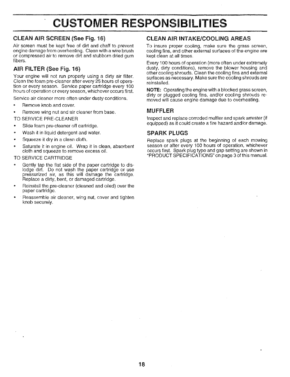
CLEAN AiR SCREEN (See Fig. 16}
Air screen must be kept free of dirt and chaff to prevent
engine damage from overheating. Clean with a wire brush
or compressed air to remove dirt and stubborn dried gum
fibers.
AIR FILTER (See Fig. 16}
Your engine will not run properly using a dirty air filter.
Clean the foam pre-deaner after every 25 hours of opera-
tion or every season. Service paper cartridge every 100
hours of operation or every season, whichever occurs first.
Service air cleaner more often under dusty conditions,
_, Remove knob and cover.
- Remove wing nut and air cleaner from base.
TO SERVICE PRE-CLEANER
*Slide foam pre-cleaner off cartridge.
-Wash it in liquid detergent and water.
-Squeeze i_:dry in a clean cloth.
Saturate it in engine oil Wrap it in clean, absorbent
cloth and squeeze to remove excess oil.
TO SERVICE CARTRIDGE
•Gently tap the flat side of the paper cartridge to dis-
lodge dirt= Do not wash the paper cartridge or use
pressurized air, as this will damage the cartridge.
Replace a dirty, bent, or damaged cartridge.
•Reinstall the pre-cleaner (cleaned and oiled) over the
paper cartridge.
- Reassemble air cleaner, wing nut, cover and tighten
knob securely.
CLEAN AiR INTAKE/COOLING AREAS
To insure proper cooling, make sure the grass screen,
cooling fins, and other external surfaces of the engine are
kept clean at all times.
Every 100 hours of operation (more often under extremely
dusty, dirty conditions), remove the blower housing and
other cooling shrouds. Clean the cooling fins and external
surfaces as necessary. Make sure the cooling shrouds are
reinstaile&
NOTE: Operating the engine with a blocked grass screen,
dirty or plugged cooling fins, and/or cooling shrouds re-
moved will cause engine damage due to overheating.
MUFFLER
Inspect and replace corroded muffler and spark arrester (if
equipped) as it could create a fire hazard and!or damage.
SPARK PLUGS
Replace spark plugs at the beginning of each mowing
season or after every 100 hours of operation, whichever
occurs first. Spark plug type and gap setting are shown in
"PRODUCT SPECIFICATIONS" on page 3 of this manual.
18
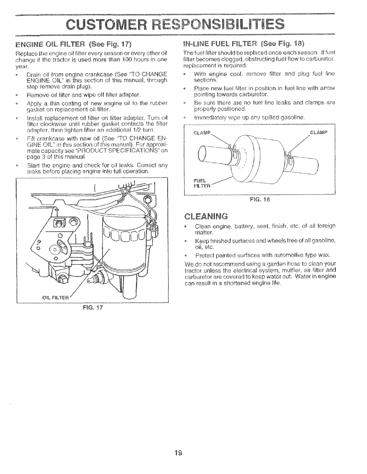
ENGINE O_L FILTER (See Fig. 17}
R__placefile er:gine oi! fitter every season or every other oi!
change if the tractor is used more than 100 hours in one
year_
Drain oil from engine crankcase (See "TO CHANGE
ENGINE OIL' in this section of this manual thTeugh
step remove drain plug).
Remove oil filter and wipe off fitter adapter.
Apply a thin coating of new engine oil to the rubber
_asket on replacement oii filter
o Install _ep_acement oil filter on tilter adapter. Turn nil
fitter clockwise until rubber gasket contacts the filter
adapter, then tighten filter an additional 1/2 turn.
o Fill crankcase with new oil (See "TO CHANGE EN-
GiNE O&/in this section of this manual) For approxi-
mate capacily see "PRODUCT SPECIFICATIONS" on
page 3 of this manual
o Sta_ the engine and check for oi! Jeaks_ Correct any
ieaks before piecing engine into fuji operation.
O_L NLTER
_NoL_NE FUEL RLTER (See F_g. 18}
The fu(q filter should be replaced once each season, tf fu_;i
filter &ecomes dogged, obstructing fuel flow to carburetor
replacement is required.
o With engine cool remove fitter and plug fuel Iine
sections
o Place new fuel fitter n position in fuel fine with arrow
pointing towards carburetor.
o Be sure there are no fuel line leaks arrd clamps are
properly positioned.
_mmediately wipe up any spi_ed gasoline
l OLAM_:_ CLANP
i
/
I
FbEL
F_LT£:R
F_Go18
CLEANING
, C!ean engine, battery, seat, finish _tc of all foreign
matter.
o Keep finished surfaces and wheels tree of all gasoline,
oil, etc.
o Protect painted surfaces with automotive type wax.
We do not recommend using a garden hose to clean your
_ractor unless the electrical system, muffler air filter and
carb_sretor are covered to keep ,_ater out. Water in engine
can result in a shortened engine life.
F_Go17
19
SERVICE ADJUSTME
...... , , ,i ,, i ,
CAUTION: BEFORE PERFORMING ANY SERVICE OR ADJUSTMENTS:
• Depress clutch/brake pedal fuUy and set parking brake.
=Place gearshift lever in neutral (N) position.
,Place attachment clutch in "DISENGAGED" position.
•Turn ignition key "OFF" and remove key.
•Make sure the blades and all moving parts have completely stopped.
,Disconnect spark plug wire from spark plug and place wire where it cannot come in contact with
plug.
TRACTOR
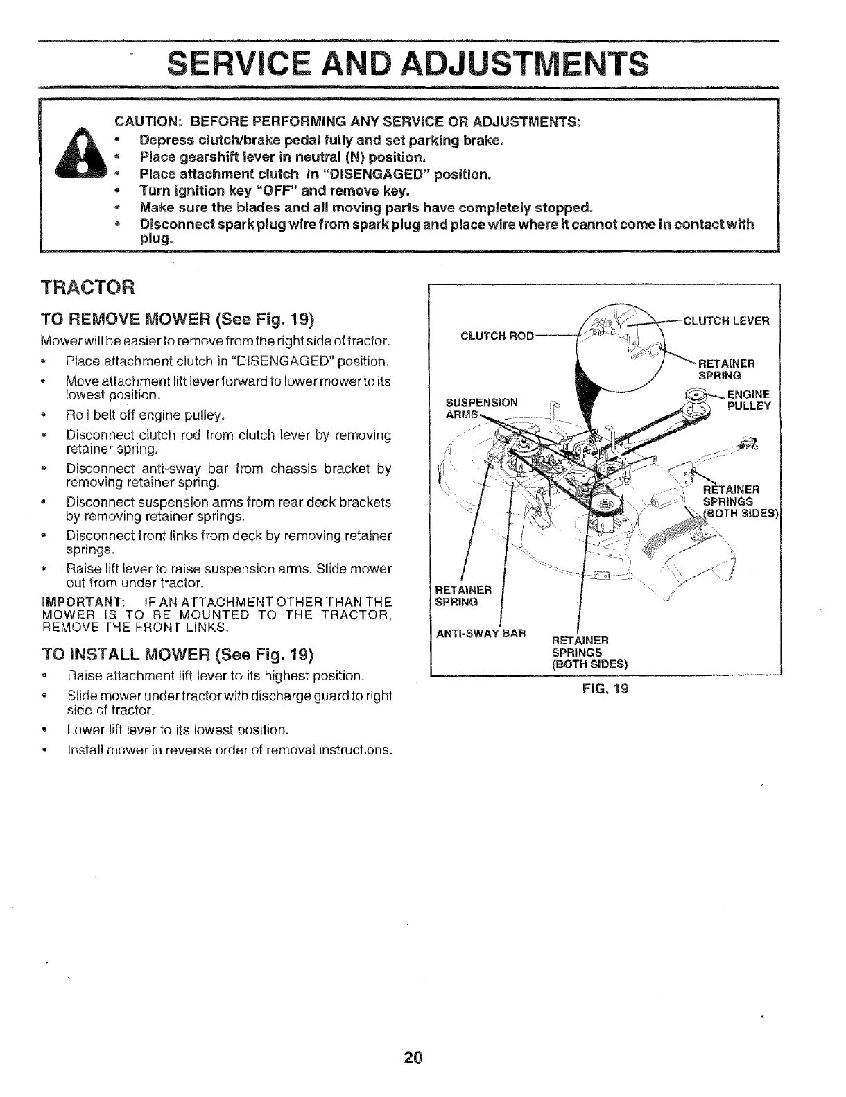
TO REMOVE MOWER (See Fig. 19)
Mower will be easier to remove from the right side of tractor.
Place attachment clutch in "DISENGAGED" position.
-Move attachment lift lever forward to lower mower to its
lowest position.
• Roll belt off engine pulley.
e Disconnect ctutch rod from clutch lever by removing
retainer spring.
Disconnect anti-sway bar from chassis bracket by
removing retainer spring.
°Disconnect suspension arms from rear deck brackets
by removing retainer springs.
= Disconnect front links from deck by removing retainer
springs
Raise lift fever to raise suspension arms. Slide mower
out from under tractor.
EMPORTANT: iF AN ATTACHMENT OTHER THAN THE
MOWER IS TO BE MOUNTED TO THE TRACTOR,
REMOVE THE FRONT LINKS.
TO iNSTALL MOWER (See Fig. 19)
• Raise attachment lift lever to its highest position.
Slide mower under tracto.r with discharge guard to right
side of tractor.
, Lower lift lever to its lowest position.
• install mower in reverse order of removal instructions.
CLUTCH ROD--
SUSPENSION
RETAINER
SPRING
ANTI-SWAY BAR
LEVER
SPRING
ENGINE
PU LL EY
RETAINER
SPRINGS
30TH SIDES
RETAINER
SPRINGS
(BOTH SIDES)
FIG. 19
2O
SERVICE AI ADJUSTMENTS
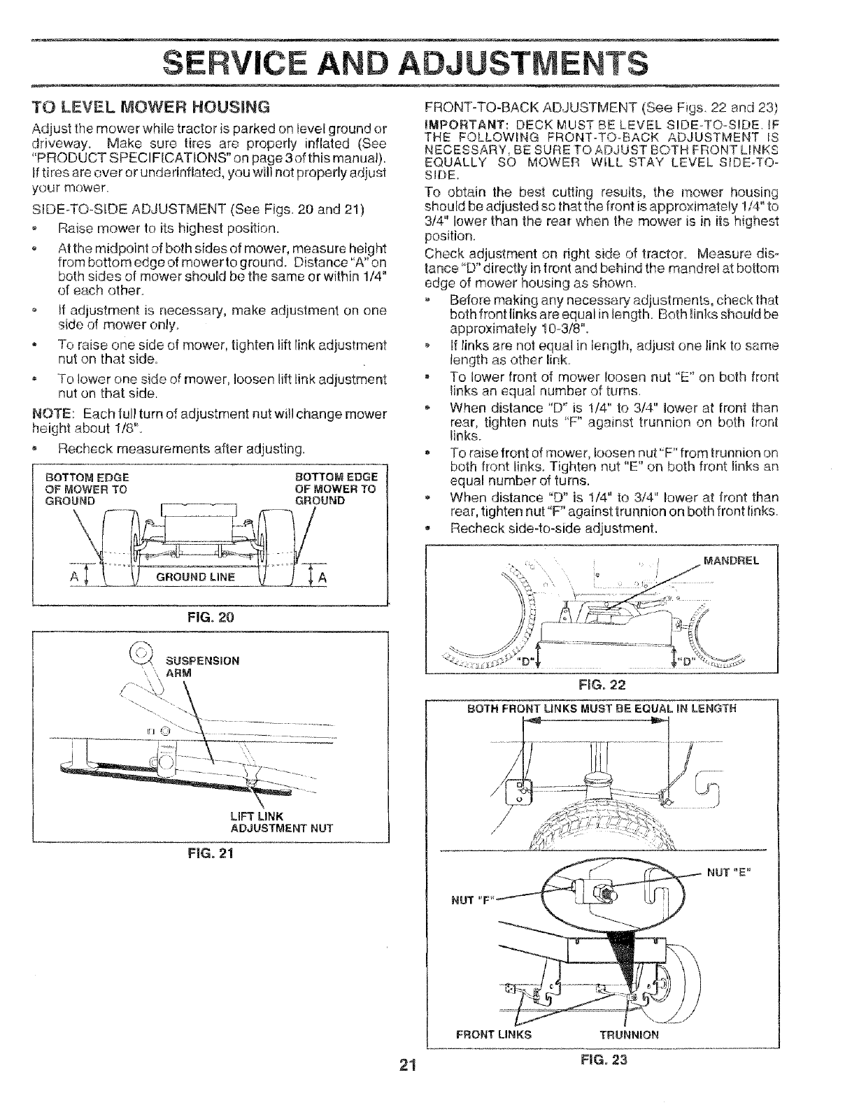
TO LEVEL MOWER HOUSING
Adjust the mower while tractor is parked on level ground or
driveway. Make sure tires are properly inflated (See
"PRODUCT SPECl FICATIONS" on page 3 of this manual).
Iftires are over or underinflated, you will not properly adjust
your mower.
SIDE-TO-SIDE ADJUSTMENT (See Figs_ 20 and 21)
Raise mower to its highest position.
At the midpoint of both sides of mower, measure height
from bottom edge of mower to ground. Distance "A" on
both sides of mower should be the same or within 1/4"
of each other_
o If adjustment is necessary, make adjustment on one
side of mower only.
* To raise one side of mower, tighten lift link adjustment
nut on that side.
= To lower one side of mower, loosen lift link adjustment
nut on that side.
NOTE: Each tull turn of adjustment nut wi!l change mower
height about 1/8".
Recheck measurements after adjusting.
BOTTOM EDGE BOTTOM EDGE
OF MOWER TO OF MOWER TO
GROUND GROUND
FIG. 20
LiFT LINK
ADJUSTMENT NUT
FiG. 21
FRONT-TO-BACK ADJUSTMENT (See Figs 22 and 23}
iMPORTANT: DECK MUST BE LEVEL SIDE-TO-SIDE _F
THE FOLLOWING FRQNT-TOoBACK ADJUSTMENT _S
NECESSARY, BE SURE TO ADJUST BOTH FRONT LINKS
EQUALLY SO MOWER WILL STAY LEVEL SIDE-TO-
SIDE.
To obtain the best cutting results, the mower housing
should be adjusted so that the front is approximately !/4" to
3/4" lower than the rear when the mower is in its highest
position.
Check adjustment on right side of tractor Measure dis°
tance"D" directly in front and behind the mandrel at bottom
edge of mower housing as shown
Before making any necessa_ adjustments, check that
beth front links are equal in length. Both !inks should be
approximately 10-3/8".
If links are not equal in lenglh, adjust ene link to same
length as other link_
= To lower front of mower loosen nut "E' on both front
links an equal number of turns,
, When distance "D_ is 1t4" to 314" lower at front than
rear, tighten nuts 'F" against trunnion on both front
links.
To raise front of mower, loosen nut"F" from trunnion on
both front links. Tighten nut "E" on both front links an
equal number of turns.
When distance "D" is 1/4" to 3/4" lower at front than
rear, tighten nut "F" against trunnion on both front links
-Recheck side-to-side adjustment.
MANDREL
FBG.22
BOTH FRONT LINKS MUST BE EQUAL IN LENGTH
NUT "_
FFIONT LINKS TRUNNION
NUT "E"
21 FIG. 23
SERVICE
............. i:m, ,,
ADJU ENTS
r,Fi _ =
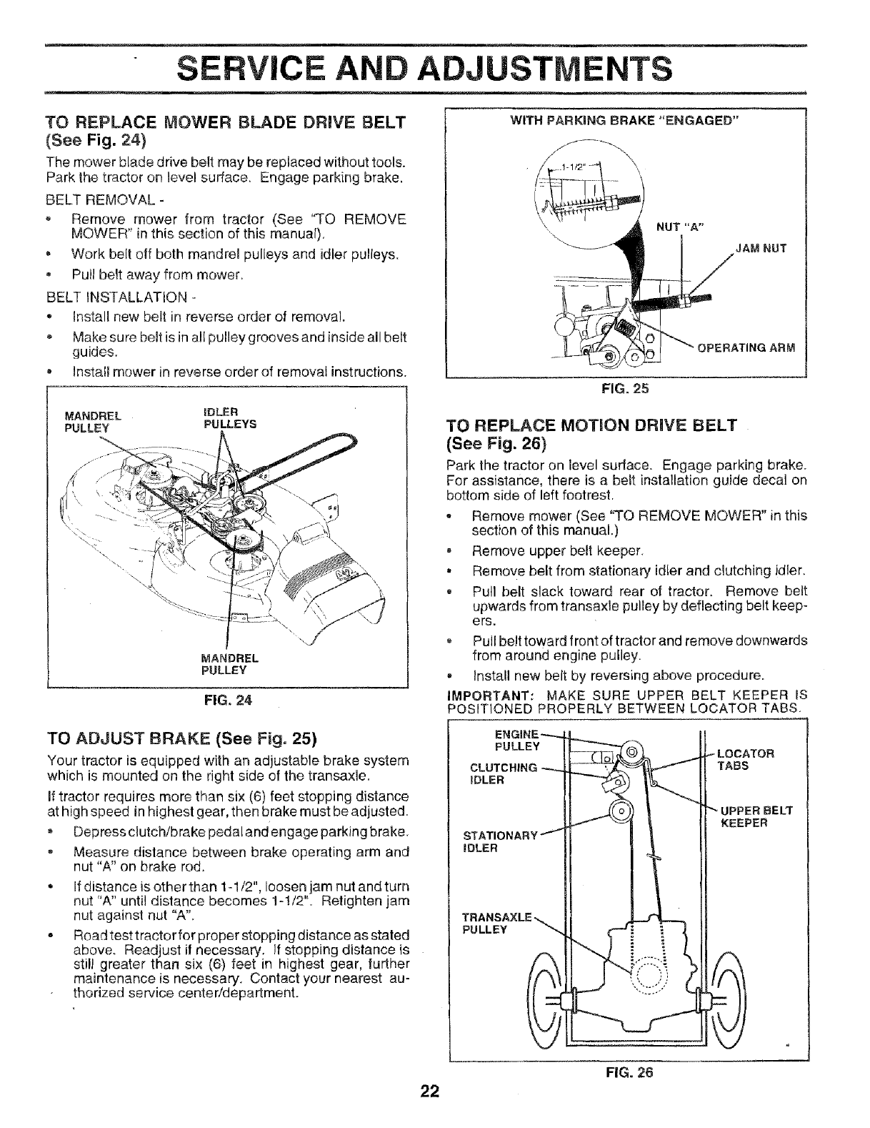
TO REPLACE MOWER BLADE DRIVE BELT
(See Fig. 24)
The mower blade drive be_t may be replaced without tools.
Park the tractor on level surface. Engage parking brake.
BELT REMOVAL -
Remove mower from tractor (See '%0 REMOVE
MOWER'* in this section of this manual).
• Work belt off both mandrel pulleys and idler pulleys.
Pull belt away from mower.
BELT iNSTALLATiON -
• Install new belt in reverse order of removal.
Make sure belt is in aglpulley grooves and inside all belt
guides.
• Install mower in reverse order of removal instructions.
MANDREL iDLER
PULLEY PULLEYS
\ \
_,IANDREL
PULLEY
FIG. 24
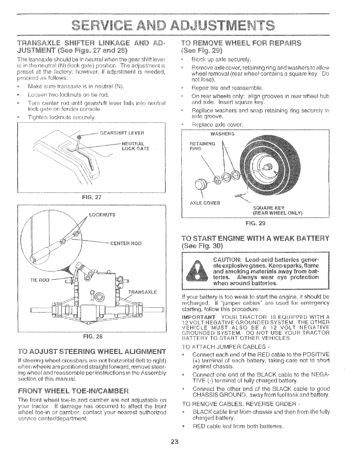
WITH PARKING BRAKE "ENGAGED"
JAM NUT
FIG. 25
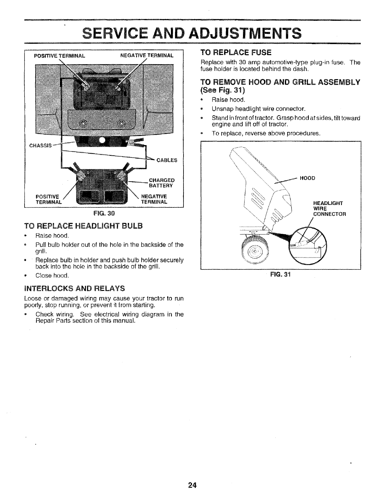
TO REPLACE MOTION DRIVE BELT
(See Fig. 26)
Park the tractor on level surface. Engage parking brake.
For assistance, there is a belt installation guide decal on
bottom side of left footrest.
* Remove mower (See 'q'O REMOVE MOWER" in this
section of this manual.)
, Remove upper belt keeper.
, Remove belt from stationary idler and dutcMng idler.
= Pull belt slack toward rear of tractor. Remove bett
upwards from transaxle pulley by deflecting belt keep-
ers.
Pul! belt toward front of tractor and remove downwards
from around engine pulley.
Install new belt by reversing above procedure.
IMPORTANT: MAKE SURE UPPER BELT KEEPER IS
POSITIONED PROPERLY BETWEEN LOCATOR TABS
TO ADJUST BRAKE (See Fig. 25)
Your tractor is equipped with an adjustable brake system
which is mounted on the right side of the transaxle.
if tractor requires more than six (6) feet stopping distance
at high speed in highest gear, then brake must be adjusted
, Depress clutch/brake pedal and engage parking brake
, Measure distance between brake operating arm and
nut "A" on brake rod
• If distance is other than 1-1/2", loosen jam nut and turn
nut "A" until distance becomes 1-!/2" Retighten jam
nut against nut "A".
o Road test tractor for proper stopping distance as stated
above. Readjust if necessary. If stopping distance is
still greater than six (6) feet in highest gear, further
maintenance is necessary Contact your nearest au-
thorized service center/department
PULLEY LOCATOR
CLUTCHING tABS
IDLER
PULLEY
UPPER BELT
KEEPER
22
FIG. 26
TI'4ANSAXLE SHIF_EI*I LINKAGE ANE) ADo
JUS°[bIENT (See [qgs. 27 and 28)
.....,r_-_n._,o_b; 5_hou!dt}_ ia neu_'ralwhen the qes.r_fl ft #vet
is in the neutra! (N) (lock gate} positior_ The adjust _ent s
preset at the _acto:!_ however, if adiustment is neede ::
_. Make s_tre transaxie is in neutral (N}
o [ oasep, _wo locknuts on !ie rod..
Turn center rod ur:_ti_gearsMft lever _ails in_o net_h_d
k,_ckgate on fender console_
Tigi_te:_ locknu_s secl;reiy.
F G, z7
TRANgAXLE
F_Go28
TO ADJUST _TEER_NG WHEEL AL_GN_ENT
if steering wheel crossbars are not horizontal (left to right}
when wheels are positioned straight forward, remove steer--
ing whee! and reassemble per instructions in the Assembly
section of this manual.
FBONT WHEEL TOE4NICA_IBER
The front wheel toeoin and camber are not adjustable on
your tractor. If damage has occurred to affect the front
wheel toe-in or camber coniact your nearest authorized
service nenteddepartment
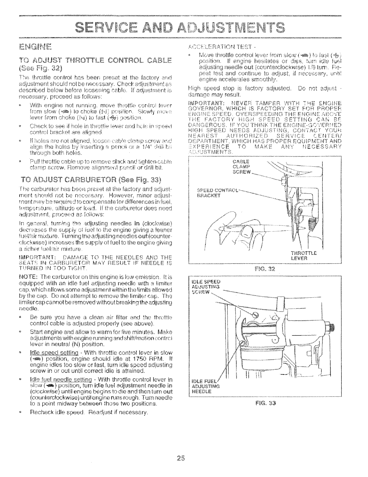
TO RE_'_OVE WHEEL FOR _EPAIRS
(See Fig. 29}
Biock up axle securely_
o, Reroove axle cover, retaining ring and washers to ailow
v_,,heelremoval (rear whee_ comtains a square key, Do
b_epa_rtire an,,_reassemble,
," On rear whe % onty sign grooves in rear wheet hub
8nd ax!e. h'_sertsquare key.
_,. Rap!ace washers and snap retaining ring sec_ _,::l_.... [
÷
AXLE COVER
SQUARE KEY
(REAR WHEEL ONLY}
_'!Go29
TO START ENGINE W_TN A WEAK BAKERY
_ee Fig_ 30}
If your batte_ is too weak to start the engine it should be
tf "iumper cabbs' are used for emergency
starting_ follow this procedure:
!#._PORTANT: YOUR TRACTOR IS EQUIPPED WITH A
i2 VOLT NEGATWE GROUNDED SYSTEM, THE OTHER
VEHICLE MUST ALSO BE A 12 VOLT NEGATIVE
GROUNDED SYSTEM DO NOT USE YOUR TRACTOR
BATTERY TO START OTHER VEHICLES,
10 ATTACH JUMPER CABLES
o Connect each _:mdof the RED cable to the POSITIVE
(+} terminal of each batlery, taking care not to short
against chassis_
o Connect one end of the BLACK cabte to the NEGA o
T!VE (-) ten_inai of fu!ly charged batte%
Connect the other end of the BLACK cable to good
CHASSIS GROUND, away from fue! tank and battery.
TO REMOVE CABLES, REVERSE ORDER -
BLACK cabte first from chassis and then from the fully
charged batter_'..
RED cable tast from both batteries.
23
SERVICE ADJUSTMENTS
POSITWETERMINAL NEGATDVETERMINAL TO REPLACE FUSE
Replace with 30 amp automotive-type plug-in fuse_
fuse holder is located behind the dash.
CABLES
CHARGED
BATTERY
POSITIVE NEGATIVE
TERMINAL TERMINAL
FIG. 30
TO REPLACE HEADLIGHT BULB
.Raise hood.
* PuZlbulb holder out of the hole in the backside of the
grill
*Replace bulb in hoJder and push bulb holder securely
back into the hole in the backside of the grill.
, Close hood.
The
TO REMOVE HOOD AND GRILL ASSEMBLY
(See Fig. 31)
Raise hood.
,Unsnap headlight wire connector.
Stand infront of tractor. Grasp hood at sides, tiJttoward
engine and liftoff of tractor.
To replace, reverse above procedures.
HOOD
HEADLIGHT
WIRE
CONNECTOR
FIG. 31
INTERLOCKS AND RELAYS
Loose or damaged wiring may cause your tractor to run
poorly, stop running, or prevent it from starting.
,Check wiring. See electrical wiring diagram in the
Repair Parts section of this manual
24
Am =
TO ADdUST TH!IO_LE OONTIIOL O£BLE
(8,.-s@Fig S2}
rh,., twetie control hr-s beer, pH<,,setat the Moiety and
adjusPaent should p,ot be necessa% Chad' adjustment as
described below before Ioose_ ihg cable If adjustment is
necessary, proceed as fe/ows:
With engine not mnnirrg, me'_e th_ottle centre! Sever
from slow (_) to choke (Id p_sition SIow!y
lever fn)m ekoke (!\i) to fast (@) p :sitio_
o Check to see if hob in l-_rotti_ !ever and hci_ h',speed
co@re4 bracl _:,tare aligned
If '._oles_re not a!if},nec! kose csb!e ck_r'Hpscrew and
attain the hoi_.s by r s_:i:ting a p_nr:il ,;t e !/4'" @il h
throuf]l_ botP holes.
Pull throttle cable _p to remove slack,and tighten c_¢,te
cbmp screw,. _:_emevea!ignme_t N.mci! or driit bit
TO A[_JUST CARBURE£TO_ (See Fig, 33}
rke carbdreto_ has be,:_l pleset at the factoR7and adjust.
mer}t shotHd r'_ot be necessaw. How(_ver_ minor adjust-
merit may ba required to compensate for differences infree!
temper?,tur6 @titude or load. If the carb_ rotor does rleed
ad),'._stment _i:roeeed as foiiows:
!n go:sere!, turning the:.Ktiusting needles ir_ (clockwise}
decreases the supply ot fue! !e tle er gine giving a !eerier
fuel/air mixture Turning the a@usting needles out (counte_
c!,ockwise) increases the sdppiv of fuel to the engine giv}ng
a richer fuel/a r mJ×tLire
IMiPOFITAHY: DAMAC,E 1O THE HEEDLES AND THE
J, X __:_E*_,: 1I',_CARBURETOR M_W RESULT IF NEEDLE _
N.!Rf_ED !N TOO TIGHT.
NOFE: Tke carbur_tor on this engine is k)w emission, it is
equipped with an idle fuel adiusting needle with a £miter
cap which alows some adjustment within the timits allowed
by tt_ecap. Do not attempt to remove the Iimiter cap. The
timiter cap cannot be removed without breaking the adjusting
_eedie.
Be su_ you have a clean air filter and the throttle
contrcl came is adjusted properly (see above).
o Start engine and ailew to warm for five minutes° Make
adiustments wit hengine running and shtt!motion centre i
lever in neutral (N) position.
-With throttte control lever Jnslow
(_) position, engine shoed idle at 1750 RPM !f
engine idles too slow or fast, turn id e speed adjusting
screw in or out untl correct idle is attained.
I@iI._fI@L - With throttle control lever in
slow (_} position, turn idle fuel adjustment needle i_
(ck.;ckwise) until engine begins to die and then turn out
(counierc!ockwise) untt engine runs rough. 'Turn needle
to a point midway between those two positions.
Recheck idle speed. Readjust if necessa%
LEVER
_LE Sl ...ED
IIQ. 33
STO
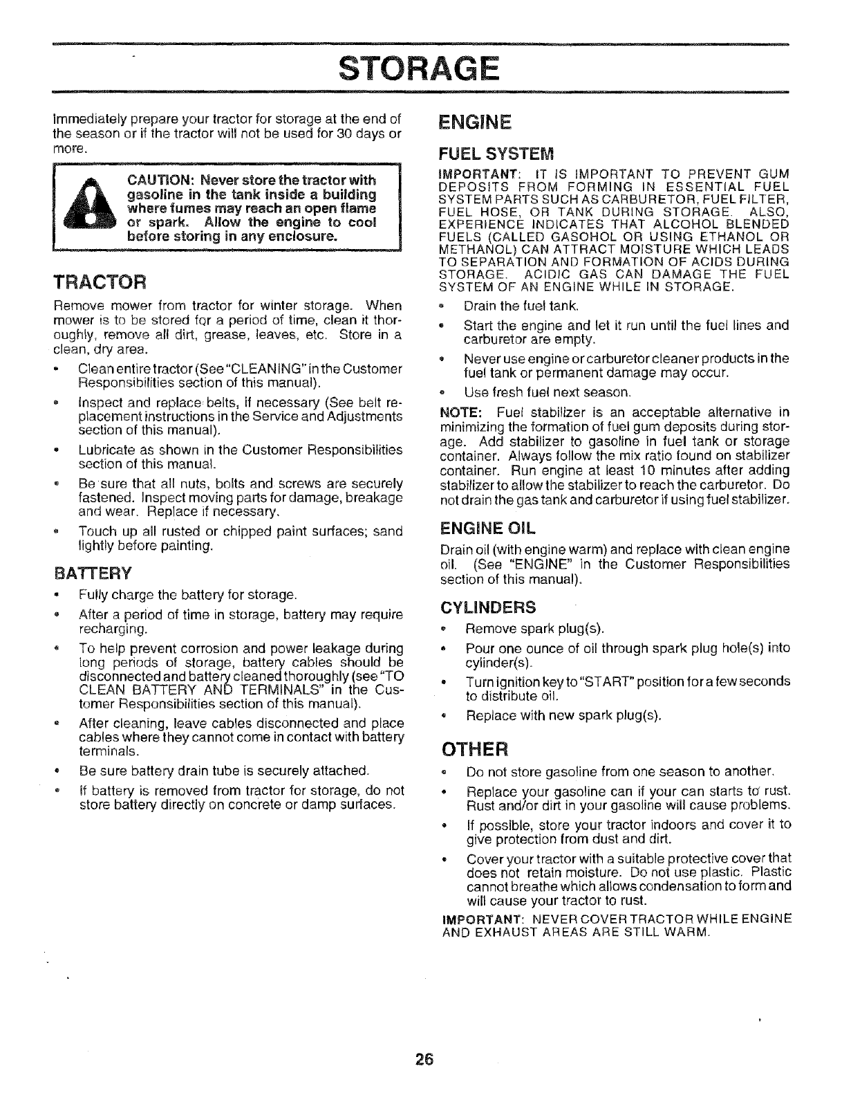
Immediately prepare your tractor for storage at the end of
the season or if the tractor will not be used for 30 days or
more.
_ or spark. AIIowthe engine to coeR
TRACTOR
Remove mower from tractor for winter storage. When
mower is to be stored fera period of time, clean it thor-
oughly, remove all dirt, grease, leaves, etc. Store in a
clean, dry area.
. Clean entire tractor (See"CLEAN iNG" in the Customer
Responsibilities section of this manuai).
Inspect and replace, belts, if necessary (See belt re-
placement instructions in the Service and Adjustments
section of this manual).
• Lubricate as shown in the Customer Responsibilities
section of this manual.
• Be sure that all nuts, bolts and screws are securely
fastened. Inspect moving parts for damage, breakage
and wear. Replace if necessary.
, Touch up all rusted or chipped paint surfaces; sand
lightly before painting.
BATTERY
• Fully charge the battery for storage.
After a period of time in storage, battery may require
recharging.
= To help prevent corrosion and power leakage during
long periods of storage, battery cables should be
disconnected and battery cleaned thoroughly (see "TO
CLEAN BATTERY AND TERMINALS" in the Cus-
tomer Responsibilities section of this manual).
•After cleaning, leave cables disconnected and place
cables where they cannot come in contact with battery
terminals.
* Be sure battery drain tube is securely attached.
If battery is removed from tractor for storage, do not
store battery directly on concrete or damp surfaces.
ENG|NE
FUEL SYSTEM
iMPORTANT: IT iS iMPORTANT TO PREVENT GUM
DEPOSITS FROM FORMING IN ESSENTIAL FUEL
SYSTEM PARTS SUCH AS CARBURETOR, FUEL FILTER,
FUEL HOSE, OR TANK DURING STORAGE. ALSO,
EXPERIENCE INDICATES THAT ALCOHOL BLENDED
FUELS (CALLED GASOHOL OR USING ETHANOL OR
METHANOL) CAN ATTRACT MOISTURE WHICH LEADS
TO SEPARATION AND FORMATION OF ACIDS DURING
STORAGE. ACIDIC GAS CAN DAMAGE THE FUEL
SYSTEM OF AN ENGINE WHILE IN STORAGE.
= Drain the fuel tank.
° Start the engine and let it run until the fuel lines and
carburetor are empty.
• Never use engine or carburetor cleaner products in the
fuel tank or permanent damage may occur.
Use fresh fuel next season.
NOTE: Fuel stabilizer is an acceptable alternative in
minimizing the formation of fuel gum deposits during stor-
age. Add stabilizer to gasoline in fuel tank or storage
container. Always follow the mix ratio lound on stabilizer
container. Run engine at least 10 minutes after adding
stabilizer to allowthe stabilizer to reach the carburetor. Do
not drain the gas tank and carburetor if using fuel stabilizer.
ENGINE OIL
Drain oil (with engine warm) and replace with clean engine
oil. (See "ENGINE" in the Customer Responsibilities
section of this manual).
CYLINDERS
,, Remove spark plug(s).
•Pour one ounce of oil through spark plug hole(s) into
cylinder(s).
• Turn ignition key to "START" position for a few seconds
to distribute oil.
,Replace with new spark plug(s).
OTHER
° Do not store gasoline from one season to another.
•Replace your gasoline can if your can starts to' rust.
Rust and/or dirt in your gasoline will cause problems.
,Ofpossible, store your tractor indoors and cover it to
give protection from dust and dirt.
•Cover your tractor with a suitable protective cover that
does not retain moisture. Do not use plastic. Plastic
cannot breathe which allows condensation to form and
will cause your tractor to rust.
IMPORTANT: NEVER COVER TRACTOR WHILE ENGINE
AND EXHAUST AREAS ARE STILL WARM.
26

Wi_ _totstert
_r_tine wil_ not tuHI r_ver
OAUSE
;: Er gina riot "CHOKED' prier#,f
Lr gin8 flooded.
,I E<_dspark plug
5 bid? ?_rfilter
6. Didyke qlte_
7. W!,_._iu fwk
CORRect]aM
8. [ c;_4a Or da_[iage;i Wi,dr@1
9 (: rt,uret.._ ,'>it o_ ;_di.isii_ e L
in ne valve,.: on! of aditsstteeu_
I Fill fun! tank
2. Sea "TO S'IART ENOiH£' in Operation s#_ction
?. Wet severs! rnirut o ._eff>m ait÷mpflno io s_ri
4. Rep_ar;e ?_art ptug
5 CIc.ant_'eplec_ MI filer
6 _-_apiacaiue! t_@r.
7. ©pan lu÷d !:.vrk arrd ::,.rburet L raft!} L-mRwith hash
9asotine and rap!; :e fi_el fiito
'.'3Check a!t wking
i} S;;:. %re Adk!st (,arbt r,:%_ i_ _;.'svi:e Adiuetm;_rfle
_ec tier
i0 Cn_tact } s_ tho_ized se_vca center/_epartrnent
Engine clicks b_1: wii_ not
sts_rt
Loss of power
I. Di£yair f!te.
2. Bad slsart pKg
S Wrak ar dead batt,x y
4. Didy fuel tilt
5. S::rI_:o d_y ftel.
6. Loose(r dare_gerlwMng
7 Calb!lretor otJt o! _,djH__lr!s_i!
2 Ergi;_e VRlve :;_!! Of ad!n;.t':x n!
4
6.
7.
8
9.
Clutch!l_rake pedalnot depress_s_d
_i_r_.chrnent clulch is engaged.
Werrk or dead battery.
tJJlown tt_sa.
Curroded batte_, tem_ina!s
Lo)se or da_ aged wiring.
Fa_fit/ gnitien switch.
Fanlty solenoid or ctar_er
f:aulty operator _rasance switr:h(esi
! CI_-, rnlr_:,pi_:e _tr fiiisf
;P,ep!ace sp_k plu9.
: I:'_ect 8rt_e or r_ [n!ao_ bakery
4Ri _:I__e f_e! riper
5 Dram fuel t'r_n,_ a_d refil with [resl gaso_ no
6 (beck ai] v_ttin-_
7 See "re Adia_ t i{}..nb!!letof n Set ii(( i_djus iienis
eectiol .
8 Cantss,c_ :¢_ aHt!',}rized :;eu4c_ centeri-]ei: artment
t Depress ck_tcWhrat_a pedal
2 D sengage atiachrn_:nt clutch
3. Roche*lee rr re_la_te L.:_._r'ry.
a Replace fuse.
'_ Clean Batter tte Irrina!s
Check a!! wirng
7 Che'xW_epk.,ce iglqtion sf4tch.
; Checkh apiece solenoid or _:tader
9 Contad an authorized service ner-te_!departr.lent.
E_c-essi_ vibralion
i, Weak or dead bailer?
2 Corroded batteJ7 terrnirlaJS.
3_ l..'.'-os_or damaged wiring
4 Faulty salt;haiti or ,.tarter.
I C ttlmg ice much grass!leo fa_t
2 Throttle in "CHOKE: posit on.
3 Build_up o! grass leaves and tra_'h under mowe£
,!. Dirty air filter
5 Low oil tewJidirt:/oi!.
6. Faulh," spark plug.
7. Dirty frJeJfilter.
8. St{4e or didy _ue!.
9 Water m fuel
I0 Spark ptug wire loose
1t Dirty engine air screen/tiffs
12 Dirty/clogged mu!fter.
!3 !_rose or damaged wiring.
14. Carburetor out o[ adjuslroent.
t 5 Engine valves out o_ adjuqment.
!. Warn bent or loose blade.
2 Bent blade mandre!
3 Loose/damaged pad(s}
1_ Recharge.'_r repb(e battery.
2 Clean battery terminals.
3 Check al_ wiring
4 Chectdraplac_s se!ehoidor static r
t Set in "Highr,i Cut' posiiion/roduce sped
2 Adjust throttle car trek
3. Clean underside of mower housing
.i Claantraplace air fitch
5Cheek ql level/change oil
6 Clean arid regap or change spark plug
7Rnplase fuei titter.
8_ Drain fuel tank and refill with fresh ga<aline
9 D_ain fuel tank and caff_uretor, rnfill tank.a[ih fresh
gasoline and raplace luel filter_
10. Connect and tightaq spark plug wire
11 Ctean engine air screen!fine
12. C_ear_/rep_ace mufltt_f
13 Check all winng
14. See"To Adjust Cerhure/or' m Sorvk'a AdiuMmente
seclien
iF,. Conia:t an authorized service centeridepa_tmenL
_. Replace blade. Irigh_'en blade boll
2 Replace blade mandrel.
3 lighten loose part(si Replace damaged fads.
£7
_S

TROUBLESHOOT! POINTS
PROBLEM
Engine continues to run
when operator leaves seat
with attachment clutch
engaged
POOF out - uneven
CAUSE
1. Faulty operator-safety presence contro(system.
1. Worn, bent or loose blade,
Mower blades wiJl not
rotate
2 Mower deck not level.
3. Buildup of grass, leaves, and trash under mower.
4, Bent blade mandrel.
5. Clogged mower deck vent holes from buildup of
grass, leaves, and trash around mandrels.
m
1 Obstruction in clutch mechanism
2. Worn/damaged mower drive belt.
3, Frozen idler pulley.
4. Frozen blade mandrel.
Poor grass discharge
Headlight(s) not working
(if so equipped)
Battery will not charge
Engine "backfires"
when turning engine
"OFF"
1. Engine speedtoo slow.
2. Travel speed too fast.
3, Wet grass.
4. Mower deck not Ievel.
5 Low/uneven tire air pressure.
6. Worn, bent or loose blade,
7. Buildup of grass, leaves and trash under mower.
8. Mower drive belt worn.
9 Blades improperly installed
10. Improper blades used
f 1. Clogged mower deck vent holes from buildup of
grass, leaves, and trash around mandrels.
t. Switch is "OFF"
2. Bulb(s ) burned out,
3. Faulty[ight switch.
4. Loose or damaged widng
5, Blown fuse,
1. Bad battery cell(s).
2. Poor cable connections.
3. Faulty regulator (if so equipped).
4. Fault_ alternator
1 Engine throttle contro! not set at "SLOW"
position for 30 seconds before stopping engine.
CORRECTION
1, Check wiring switches and connections, If net
corrected, contact an authorized service center/
department.
Replace blade. Tighten blade bolt.
2. Level mower deck.
3, Clean underside of mower housing_
4. Replace blade mandrel
5, Clean around mandrels to open vent holes.
1 Remove obstruction.
2. Replace mower drive bell
3, Replace idler pulley,
4. Replace blade mandrel
1 Place throttle control in "FAST" position,
2. Shift to slower speed.
3, Allow grass to dry before mowing.
4, Level mower deck.
5. Check tires for proper air pressure.
6. Replace/sharpen blade. Tighten blade bolt.
7. Clean underside of mower housing.
8, Replace mower drive belt,
9. Reinstall blades sharp edge down.
10. Replace with blades listed in this manual.
11. Clean around mandrels to open vent holes
f. Turn switch "ON".
2 Replace bulb(c).
3. Check/replace light switch_
4. Check wiring and conrlections.
5, Replace luse,
1. Replace battery
2. Check/clean all connections.
3. Replace regulator.
4, Replace alternator.
1. Move throttle control to "SLOW" position and allow
to idle for 30 seconds before stopping engine.
28
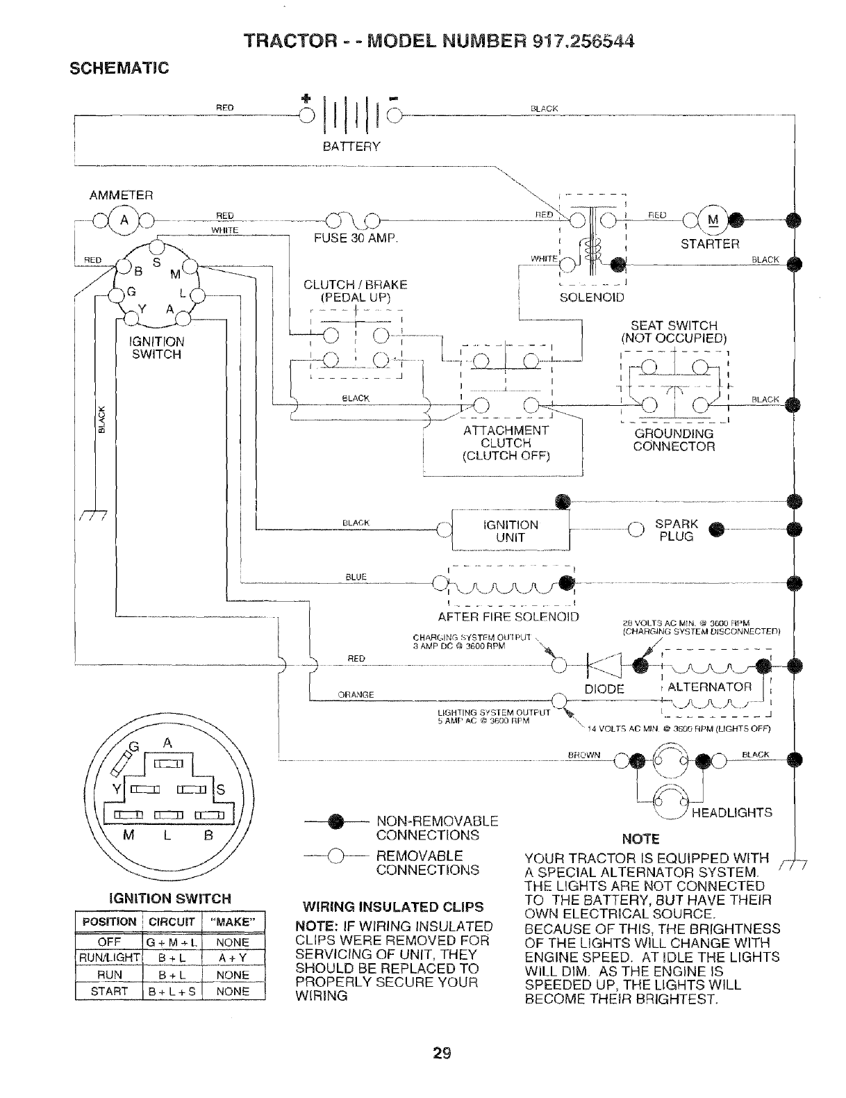
SCHEMATIC
TRACTOR = - MODEL NUMBER 9!7.256544
[RED
BA'I-FERY
BLACK
G L
IGNITION
SWITCH
IGNITION SWITCH
POSITION CIRCUIT "MAKE"
, ]
OFF G + M ÷ L NONE
RUN!LIGHT B + L A + Y
RUN B + L NONE
START B + L + S NONE
BLACK
BLACK
BLACK
BLUE
)
!
gl
...............................Q ...............................................
(_"I IGNITION [_..... (-) SPARK _l_ ................ -ll_
....I......................._!_ ......I -- PLUG
I I
C,_\.>.>.>._Aj-Q........................_I
I ......... I
AFTER FIRE SOLENOID 28 VOLTS AO MIN, @ 3600 FIPM
(CHARGING SYSTEM DISCONNECTED)
CHARGING SYSTI'M C)U'[ PU] ,
3 AMP DC @ 3600 RPM "_ /
I
DIODE
LIGHTING S_S/EM OUTPUT _ I _1
5 AMP AC @ 3600 RPM '.\ ...........
" 14 VOLTS AC MIN @3_dO RPM (LIGHTS OFF)
...................................................C o %eo
NON-REMOVABLE ',,. /HEADLIGHTS
NOTE
YOUR TRACTOR IS EQUIPPED WITH
A SPECIAL ALTERNATOR SYSTEM.
THE LIGHTS ARE NOT CONNECTED
TO THE BATTERY, BUT HAVE THEIR
OWN ELECTRICAL SOURCE.
BECAUSE OF THIS, THE BRIGHTNESS
OF THE LIGHTS WILL CHANGE WITH
ENGINE SPEED. AT IDLE THE LIGHTS
WILL DIM. AS THE ENGINE IS
SPEEDED UP, THE LIGHTS WILL
BECOME THEIR BRIGHTEST.
/Z
CONNECTIONS
--_')--- REMOVABLE
CONNECTIONS
WIRING INSULATED CLIPS
NOTE: IF WIRING INSULATED
CLIPS WERE REMOVED FOR
SERVICING OF UNIT, THEY
SHOULD BE REPLACED TO
PROPERLY SECURE YOUR
WIRING
29

21
!_I',!liii:
......."-.,......".g:O'i
_2
°\
.J
f
I.
_ Zg
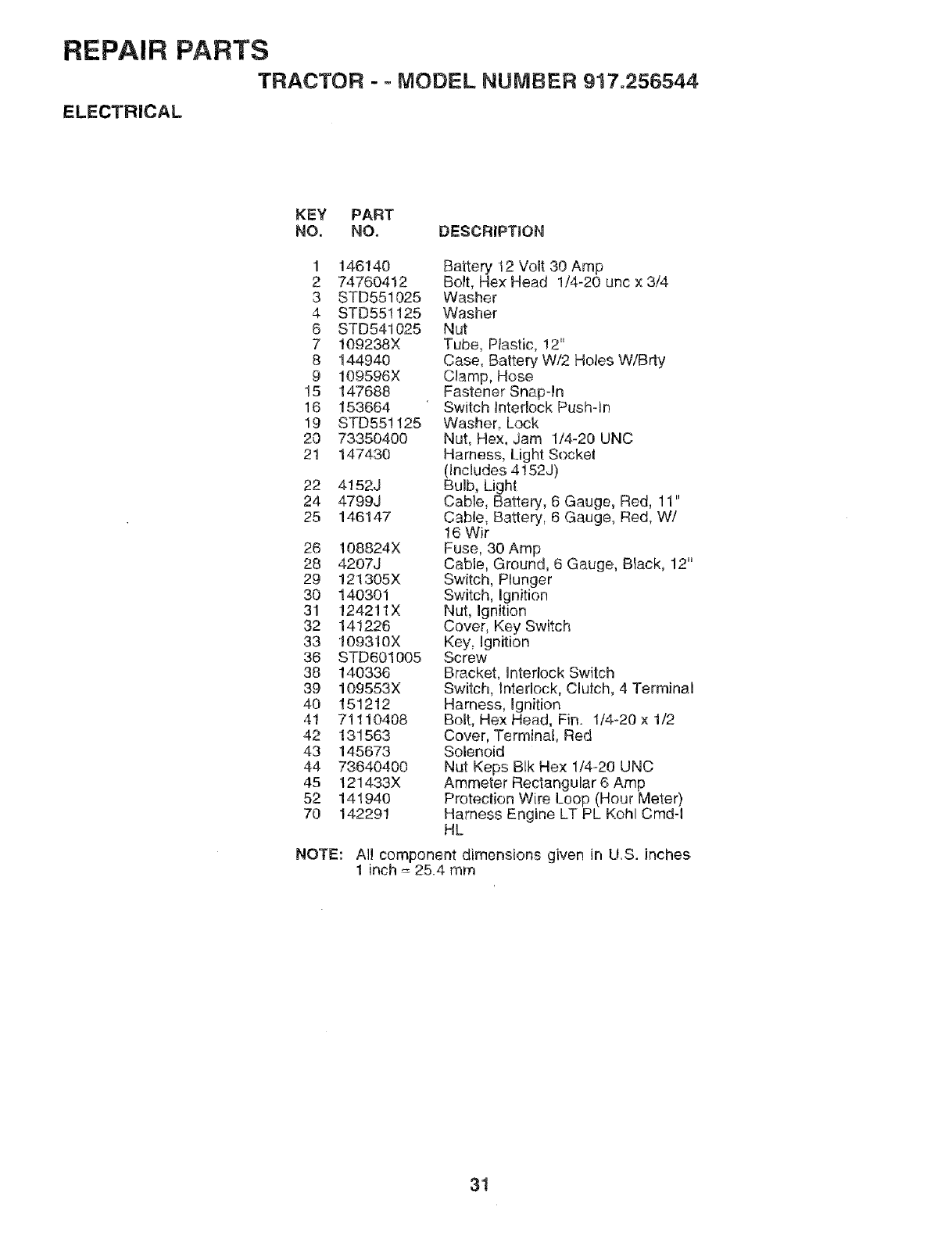
REPAIR PARTS
TRACTOR - ° MODEL NUMBER 917.256544
ELECTRICAL
KEY PART
NO, NO. DESCRIPTION
1 146140
2 74760412
3 STD551025
4 STD55!125
6 STD541025
7 109238X
8 144940
9 109596X
15 147688
16 153664
19 STD551125
20 73350400
21 147430
22 4152J
24 4799J
25 146147
26 108824X
28 4207J
29 121305X
30 140301
31 124211X
32 141226
33 !09310X
36 STD601005
38 140336
39 109553X
40 151212
41 71110408
42 131563
43 145673
44 73640400
45 121433X
52 141940
70 142291
Battery 12 Volt 30 Amp
Bolt, Hex Head 1/4-20 unc x 3/4
Washer
Washer
Nut
Tube, Plastic, 12"
Case, Battery W/2 Holes W/Brty
Clamp, Hose
Fastener Snap-In
Switch Interlock Pushqn
Washer, Lock
Nut, Hex, Jam 1/4-20 UNC
Harness, Light Socke!
(Includes 4152J)
Bulb, Light
Cable, Battery, 6 Gauge, Red, 11"
Cable, Battery, 6 Gauge, Red, W/
16 Wir
Fuse, 30 Amp
Cable, Ground, 6 Gauge, Black, 12"
Switch, Plunger
Switch, Ignition
Nut, Ignition
Cover, Key Switch
Key, Ignition
Screw
Bracket, Interlock Switch
Switch, Interlock, Clutch, 4 Terminal
Harness, Ignition
Bolt, Hex Head, Fin. 1/4-20 x 1/2
Cover, Terminal, Red
Solenoid
Nut Keps Blk Hex 1/4-20 UNC
Ammeter Rectangular 6 Amp
Protection Wire Loop (Hour Meter)
Harness Engine LT PL Kohl Cmd-I
HL
NOTE: All component dimensions given in U.S. inches
1 inch = 25.4 mm
3!
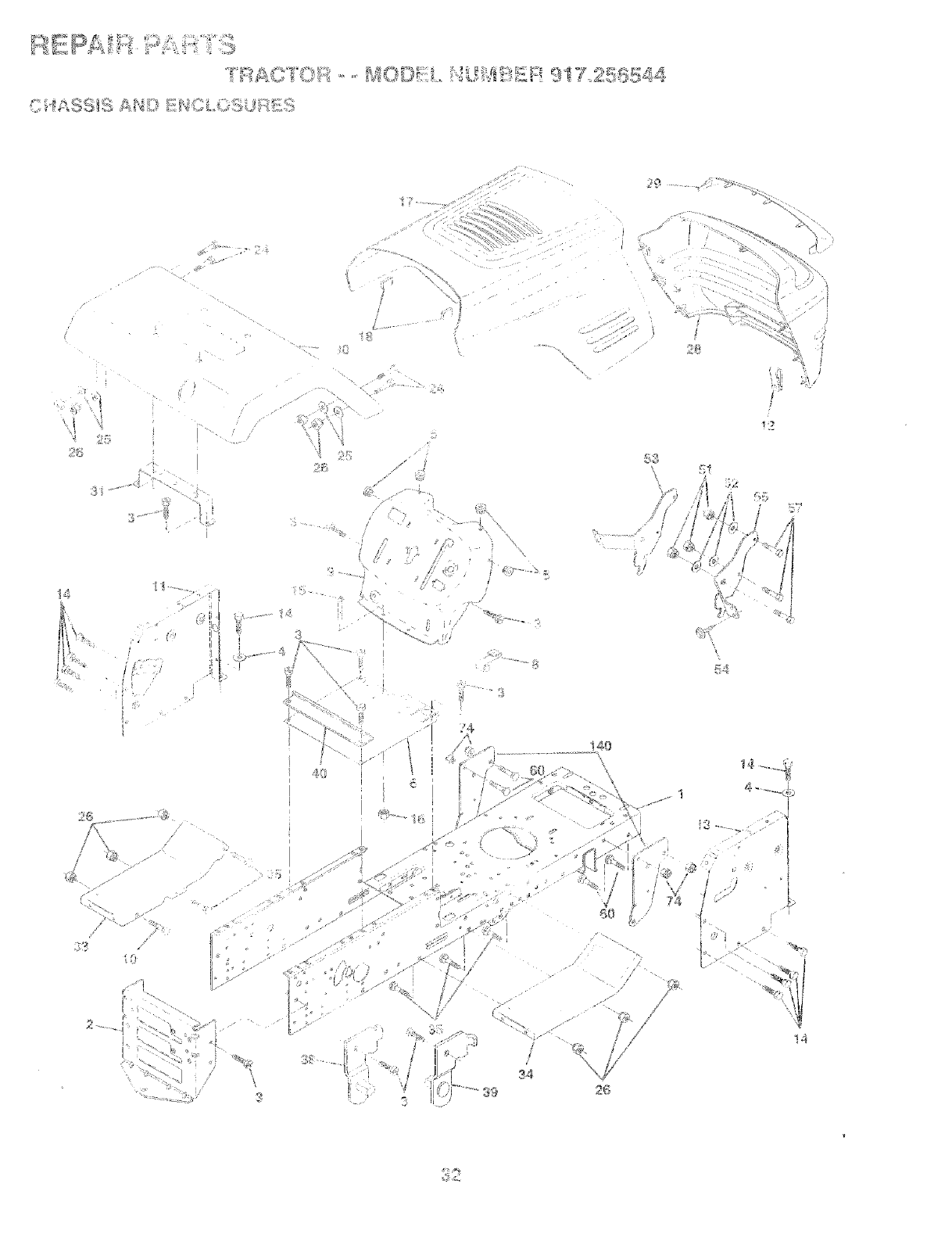
39 2G
!4
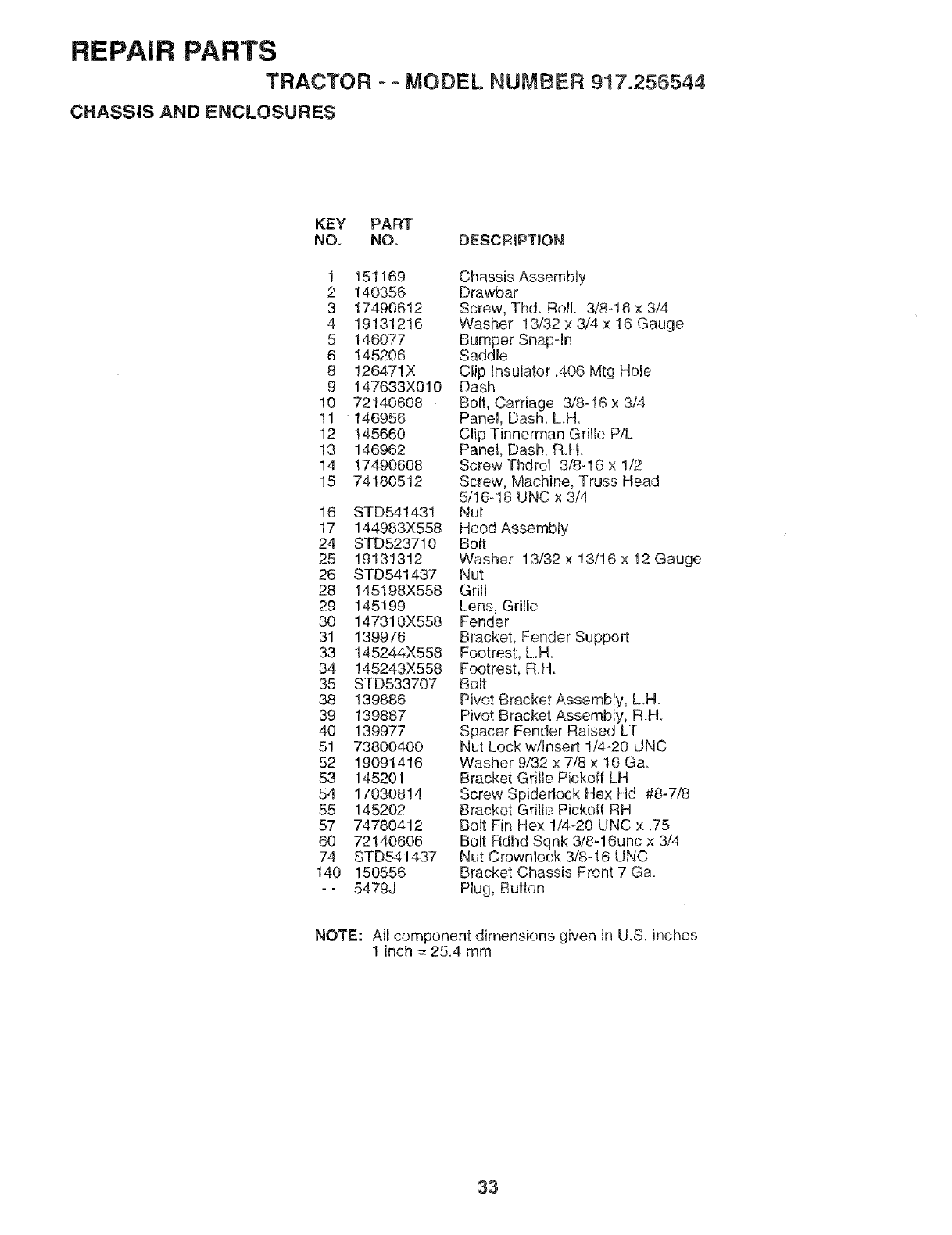
REPAIR PARTS
TRACTOR --MODEL NUMBER 917.256544
CHASSIS AND ENCLOSURES
KEY PART
NO. NO. DESCRIPTION
1 151169
2 140356
3 17490612
4 19131216
5 146O77
6 145206
8 126471X
9 147633X0!0
10 72140608 .
tl 146956
12 145660
13 146962
14 174906O8
15 7418O512
16 STD541431
17 144983X558
24 STD523710
25 19131312
26 STD541437
28 145198X558
29 145199
30 147310X558
31 139976
33 145244X558
34 145243X558
35 STD533707
38 139886
39 139887
40 139977
51 7380O400
52 19091416
53 145201
54 17030814
55 145202
57 74780412
60 721406O6
74 STD541437
140 15O556
-- 5479J
Chassis Assembly
Drawbar
Screw, Thd. Roll 3/8o!6 x 3/4
Washer 13/32 x 3/4 x 16 Gauge
Bumper Snapqn
Saddle
Clip Insulator .406 Mtg Hole
Dash
Bolt, Carriage 3/8-16 x 3/4
Panel, Dash, L.H.
Clip Tinnerman Grille P/L
Panet, Dash, R.H.
Screw Thdrol 3/._}-16x 1/2
Screw, Machine, Truss Head
5/16-18 UNC x 3/4
Nut
Hood Assembly
Bolt
Washer 13/32 x 13/16 x 12 Gauge
Nut
Grill
Lens, Grille
Fender
Bracket, Fender Support
Footrest, L.H.
Footrest, R.H.
Bolt
Pivot Bracket Assembly, L.H.
Pivot Bracket Assembly, R.H.
Spacer Fender Raised LT
Nut Lock w/Insert 1/4-20 UNC
Washer 9/32 x 7/8 x t6 Ga.
Bracket Grille Pickoff LH
Screw Spiderlock Hex Hd #8-7/8
Bracket Grille Pickoff RH
Bolt Fin Hex 1/4-20 UNC x .75
Bolt Rdhd Sqnk 3/8-16unc x 3/4
Nut Crownlock 3/8-!6 UNC
Bracket Chassis Front 7 Ga.
Plug, Button
NOTE: Atl component dimensions given in U.S. inches
1 inch = 25.4 mm
33
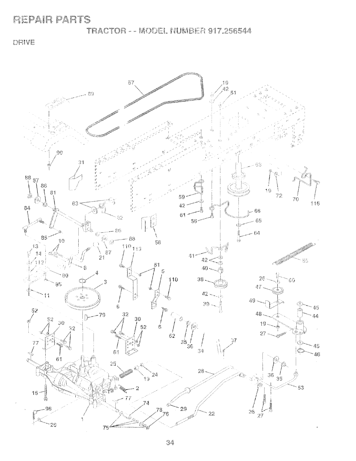
_4
J
_b _S
.7
__ _ _ _'s_
_8
\
t !0
/
7_
ti t
,i!_ I,
3_
• l
7_
4_ .....
;7
?_
-¢_!_
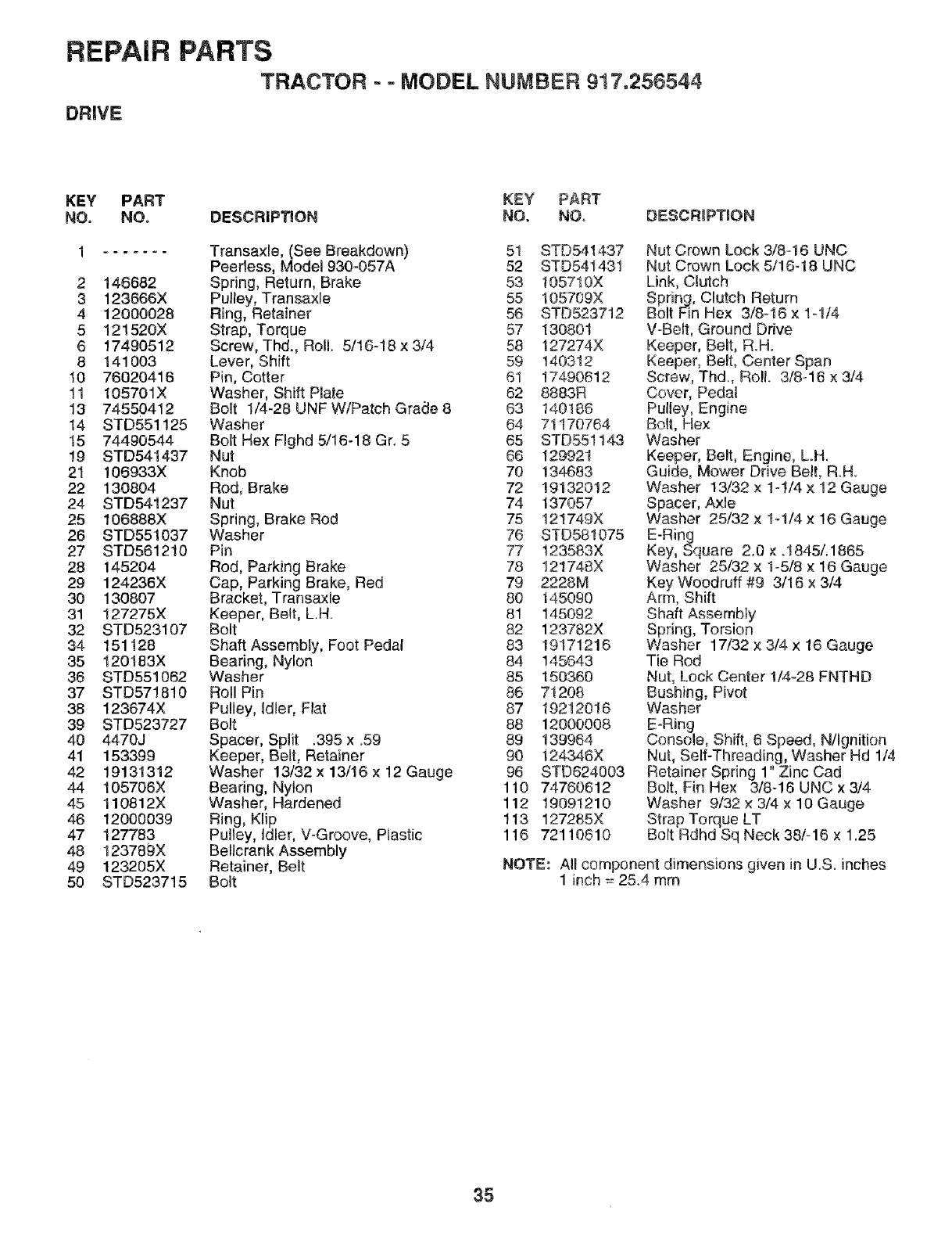
REPAIR
DRIVE
PARTS
TRACTOR - o MODEL NUMBER 917,256544
KEY
NO.
2
3
4
5
6
8
10
11
13
14
15
19
21
22
24
25
26
27
28
29
30
31
32
34
35
38
37
38
39
4O
41
42
44
45
46
47
48
49
5O
PART
NO.
146682
123666X
12000028
121520X
17490512
141003
76020416
105701X
74550412
STD551125
7449O544
STD541437
106933X
130804
STD541237
106888X
STD551037
STD561210
145204
124236X
130807
127275X
STD523107
151128
120183X
STD55! 062
STD571810
123674X
STD523727
4470J
153399
19131312
105706X
110812X
12000039
127783
123789X
123205X
STD523715
KEY PART
DESCRIP_ON NO. NO, DESCRiPTiON
Transaxle, (See Breakdown) 51 STD541437
Peerless, Model 930-057A 52 STD541431
Spring, Return, Brake 53 105710X
Pulley, Transaxle 55 105709X
Ring, Retainer 56 BTD523712
Strap, Torque 57 130801
Screw, Thd., Roll. 5/16-18x314 58 127274X
Lever, Shift 59 140312
Pin, Cotter 61 17490612
Washer, Shift Plate 02 8883R
Bolt 1/4-28 UNF W/Patch Graae 8 63 140186
Washer 64 71170764
Bolt Hex Flghd 5/16-18 Gr. 5 65 STD551143
Nut 68 129921
Knob 70 134683
Rod, Brake 72 19132012
Nut 74 137057
Spring, Brake Rod 75 121749X
Washer 76 STD581075
Pin 77 123583X
Rod, Parking Brake 78 121748X
Cap, Parking Brake, Red 79 2228M
Bracket, Transaxfe 80 145090
Keeper, Belt, LH 81 145092
Bolt 82 123782X
Shaft Assembly, Foot Pedal 83 19171216
Bearing, Nylon 84 145643
Washer 85 150360
Roll Pin 86 71208
Pulley, idler, Flat 87 19212018
Bolt 88 12000008
Spacer, Split .395 x .59 89 139984
Keeper, Belt, Retainer 90 124346X
Washer 13/32 x 13/16 x 12 Gauge 96 STD824003
Bearing, Nylon 110 74780612
Washer, Hardened 112 19091210
Ring, KIip 113 127285X
Pulley, Idler, V-Groove, Plastic 116 72110610
Be!lcrank Assembly
Retainer, Belt
Bolt
Nut Crown Lock 3,18-16 UNC
Nut Crown Lock 5/!6-18 UNC
Link, Clutch
Spring, Clutch Return
Bolt Fin Hex 3/8-16x 1-1/4
V-Belt, Ground Drive
Keeper, Belt, RH_
Keeper, Belt, Center Span
Screw, Thd, Roll. 3/8-16 x 3/4
Cover, Pedal
Pulley, Engine
Bolt, Hex
Washer
Keeper, Belt, Engine, LH.
Guide, Mower Drive Belt, R.H.
Washer 13/32 x 1-!/4 x 12 Gauge
Spacer, Axle
Washer 25/32 x 1-1/4 x 16 Gauge
E-Ring
Key, Square 2.0 × ot845/o1865
Washer 25/32 x 1-5/8 x 16 Gauge
Key Woodruff #9 3/16 x 3/4
Arm, Shift
Shaft Assembly
Spring, Torsion
Washer 17/32 x 3/4 x 16 Gauge
Tie Rod
Nut, Lock Center !/4-28 FNTHD
Bushing, Pivot
Washer
EaRing
Console, Shift, 6 Speed, N/Ignition
Nut, Self-Threading, Washer Hd 1/4
Retainer Spring 1" Zinc Cad
Bolt, Fin He× 3/8-16 UNC x 3/4
Washer 9/32 x 3/4 x 10 Gauge
Strap Torque LT
Bolt Rdhd Sq Neck 38/-16 x 1.25
NOTE: All component dimensions given in U.S. inches
1 inch = 25.4 mm
35
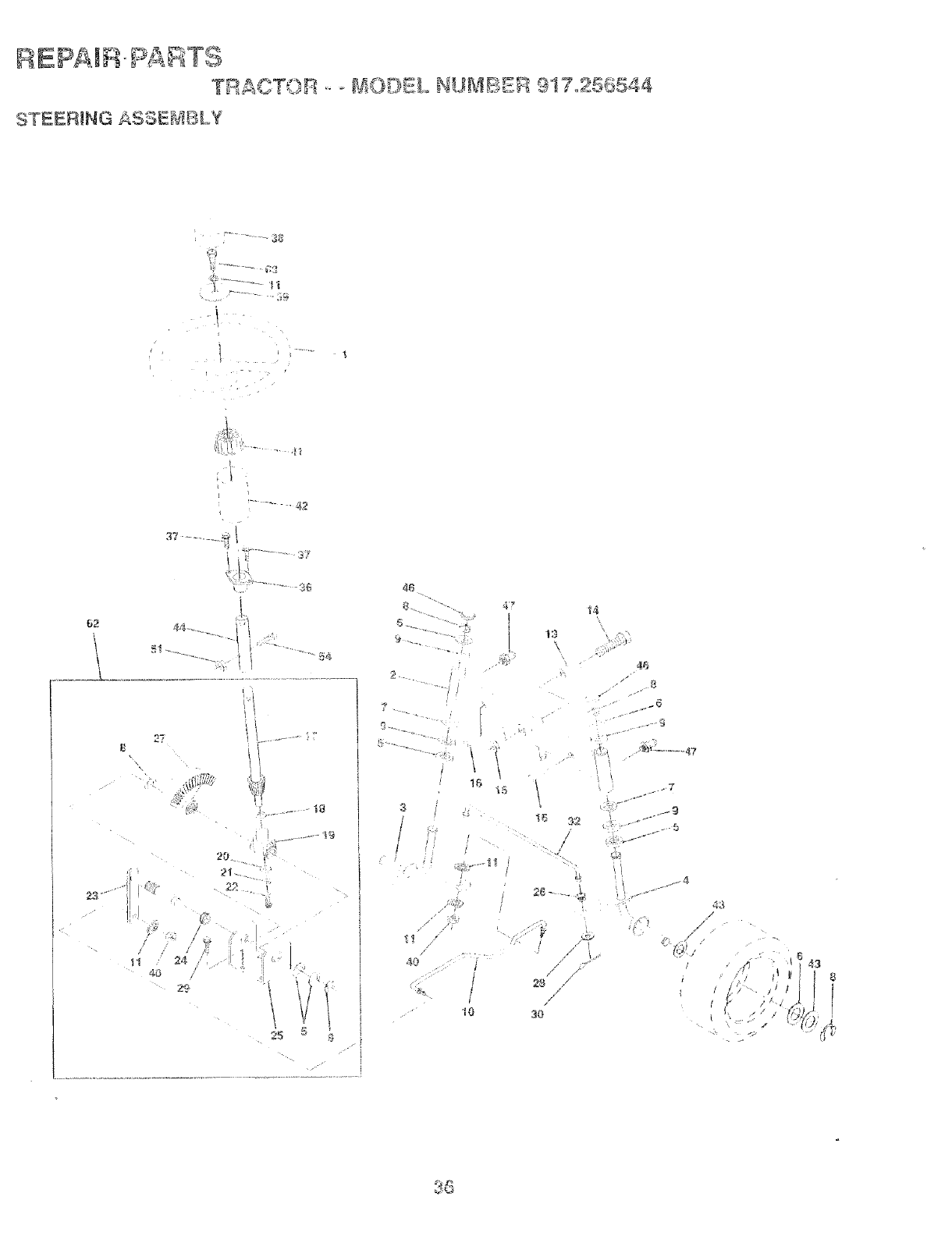
_EpAIR PAinTS
G ASSertiVeLY
SI"ESR_N
62 4_1,.....
23"
20.
21
18
24
4_
\
2_ 5
3 :_; t6 3A
/
/
4e_ t
z'" I
• _!!i
3O
43
/
//
36
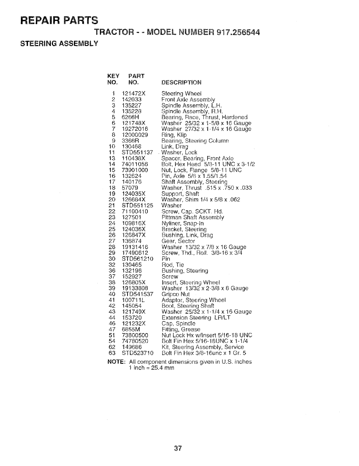
REPAIR PARTS
TRACTOR - -MODEL NUMBER 917.256544
STEERING ASSEMBLY
KEY PAF_T
NO. NO, DESCRIPTION
1 121472X
2 142033
3 135227
4 135228
5 6266H
6 !21748X
7 19272016
8 12000029
9 3366R
10 130468
11 STD551137
13 110438X
14 74011O56
15 73901000
16 132624
17 140176
18 57079
19 !24035X
20 126684X
21 STD551125
22 71100410
23 127501
24 109816X
25 124036X
26 126847X
27 136874
28 19131416
29 17490612
3O STD561210
32 13O465
36 132196
37 152927
38 126805X
39 19133808
40 STD541537
41 100711L
42 !45054
43 121749X
44 153720
46 121232X
47 6855M
51 73800500
54 74780520
62 149686
63 STD523710
Steering Wheel
Front Axle Assembly
Spindle Assembly, LH
Spindle Assembly, RH.
Bearing, Race, Thrust, Hardened
Washer 25/32 x 1-5/8 x 16 Gauge
Washer 27/32 x 1-1/4 x 16 Gauge
Ring, Klip
Bearing, Steering Column
Link, Drag
Washer, Lock
Spacer, Bearing, Front Axle
Bolt, He× Head 5/8-11 UNC x 3-1/2
Nut, Lock, Flange 5!8-1t UNC
Pin, Axle 5/8 × 1.55/1 °54
Shaft Assembly, Steering
Washer, Thrust .515 x.750 x.033
Support, Shaft
Washer, Shim 1/4 x 5/8 x .062
Washer
Screw, Cap. SCKT. Hd.
Pittman Shaft Assembly
Nyliner, Snap-In
Bracket, Steering
Bushing, Link, Drag
Gear, Sector
Washer 13/32 x 7/8 x 16 Gauge
Screw, Thd, Roll. 3/8-16 x 3/4
Pin
Rod, Tie
Bushing, Steering
Screw
Insert, Steering Wheel
Washer 13/32 x 23/8 x 8 Gauge
Gdpco Nut
Adaptor, Steering Wheel
Boot, Steering Shaft
Washer 25/32 x 1-1/4 x 16 Gauge
Extension Steering LR/LT
Cap, Spindle
Fitting, Grease
Nut Lock Hx w/Insert 5/16-18 UNC
Bolt Fin Hex 5/16dSUNC x 1-1/4
Kit, Steering Assembly, Service
Bolt Fin Hex 3/8°16unc x 1 Gr. 5
NOTE: All component dimensions given in U_S. inches
! inch = 25.4 mm
37
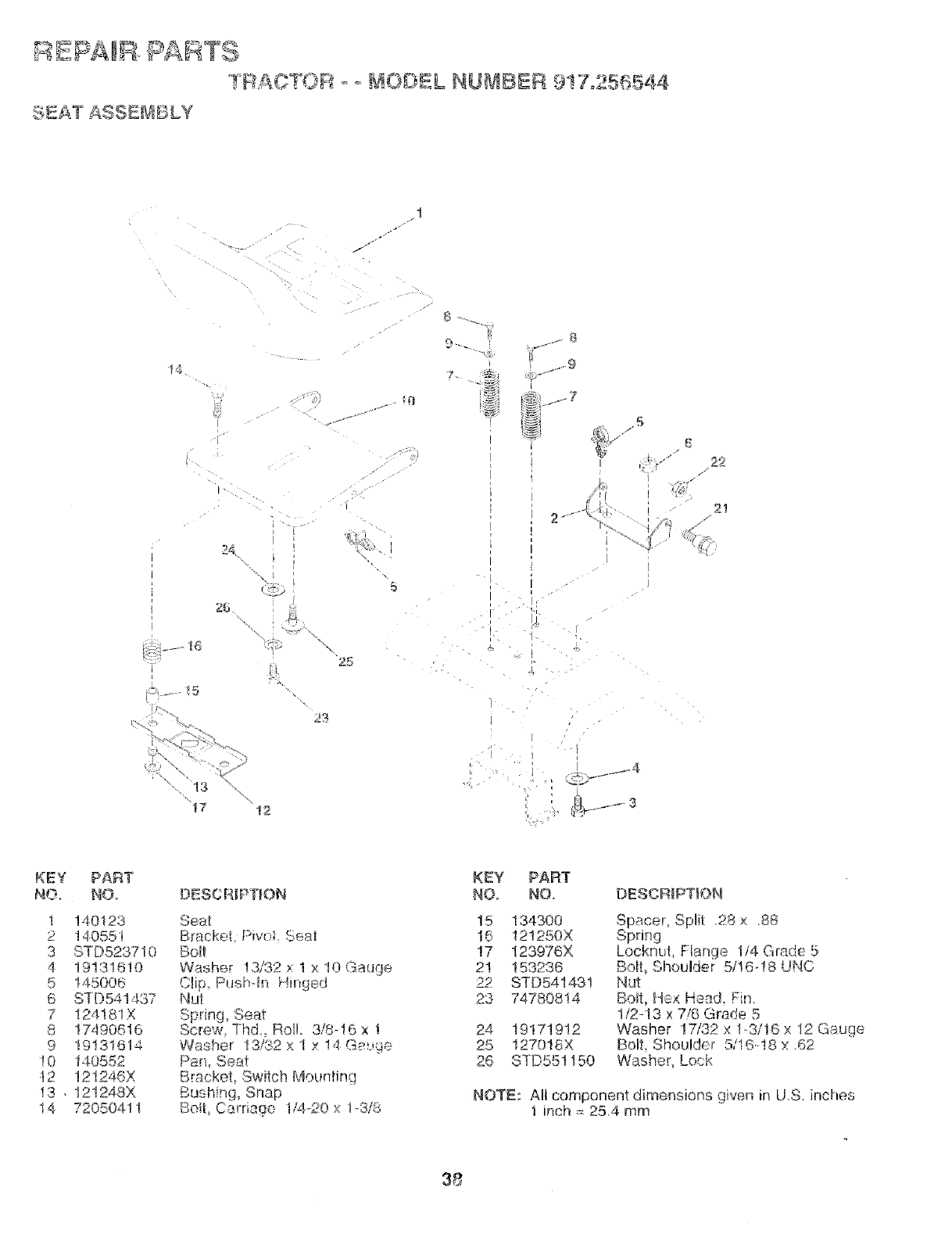
] FL&O :'@R [ !OE}EL NU , BBR 9!7o25 s544
:SEAT ASSE_SBLY
.t
/-
24
f!,
23
5
25
7
.5
r r
2_
2!
KEY PART
NO. NO
1 140123
2 140551
3 STD523710
4 19131610
5 145006
6 STD541437
7 !24181X
8 17490616
9 19131614
!0 140552
_2 12!246X
13, 12!248X
14 72050411
DESCRiPTiON
Seat
Bracket Pwoi Sea_
Bo!t
Washer !3/32 × 1 x 10 Gauge
Clip Pusbqn Hinged
Iqut
Spring, Seat
Screw Thd, Roll 3/8-16 x 1
Washer t3/32 x 1 x !4 G_'-mge
Pan, Seat
Bracket, Switch Mounting
Bushing, Snap
Bolt, Carriage I/4_20 x 1-3/8
KEY PART
NO,_ NOo
!5 13430O
16 !21250X
!7 123976X
21 153236
22 STD541431
23 74780814
24 19171912
25 !270t8X
26 STD551150
DESGR[PTIO_',_
Spacer, Split .28 × 88
Spring
Locknut, Flange 1i4 Grade 5
Boil, Shoulder 5/!6-18 UNC
Nut
Bolt, Hex Head. Fin
1/2-13 x 7/8 Grade 5
Washer 17/52 x 13/!6 x 12 Gauge
Bolt, Shoulder 5/I618 x 62
Washer, Lock
NOTE: All component dimensions given in U.S. inches
t inch = 25.4 mm
38
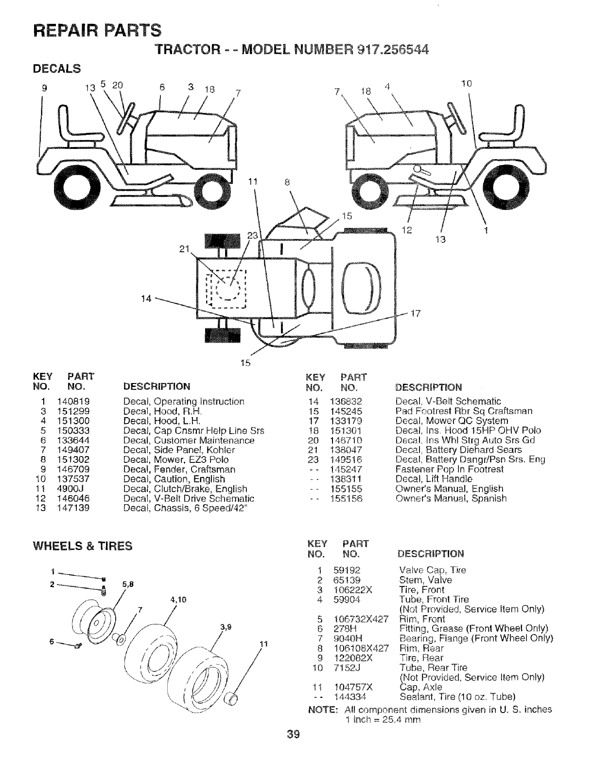
REPAIR PARTS
TRACTOR -oMODEL NUMBER 917.256544
DECALS
9 13 5 20 6 3 !8
\ 7 7, 18 4
10
1t 8
!4
21
12 13
!7
15
KEY PART KEY PART
NO. NO. DESCRIPTION NO. NO,
1 140819 Decal, Operating Instruction 14 136832
3 151299 Decal, Hood, R.H. 15 145245
4 151300 Decal, Hood, L.H° 17 133179
5 150333 Decal, Cap Cnsmr Help Line Srs 18 151301
6 133644 Decal, Customer Maintenance 20 146710
7 149407 Decal, Side Panel, Kohler 21 138047
8 151302 Decal, Mower, EZ3 Polo 23 149516
9 146709 Decal, Fender, Craftsman - - 145247
10 137537 Decal, Caution, English -- 138311
11 4900J Decal, Clutch/Brake, English _o 155155
12 146046 Decal, V-Belt Drive Schematic - - 155156
13 147139 Decal, Chassis, 6 Speed/42"
DESCRIPTmON
Decal, V-Belt Schematic
Pad Footrest Rbr Sq Craftsman
Decal, Mower QC System
Decal, ins. Hood 15HP OHV Polo
Decal. ins Whl Strg Auto Srs Gd
Decal, Battery Diehard Sears
Decal Battery DangdPsn Srs. Eng
Fastener Pop ]n Footrest
Decal, Lift Handle
Ownees Manual, English
Owner's Manual, Spanish
WHEELS &TIRES KSY PART
NO, NO.
1 59192
I _._....__.___ 2 65139
2----_._.._ 5,8 3t 06222X
4,10 4 59904
11
39
DESCRIPTION
5 106732X427
6 278H
7 9040H
8 106108X427
9 122082X
10 7152J
11 104757X
o- 144334
Valve Cap, Tire
Stem, Valve
Tire, Front
Tube, Front Tire
(Not Provided, Service Item Only)
Rim, Front
Fitting, Grease (Front Wheel Only)
Bearing, Flange (Front Wheel Only)
Rim Rear
Tire_ Rear
Tube, Rear Tire
(Not Provided, Service Item Only)
Cap, Axle
Sealanl, Tire (10 oz. Tube)
NOTE: A!l component dimensions given in U. S. inches
1 inch = 25.4 mm
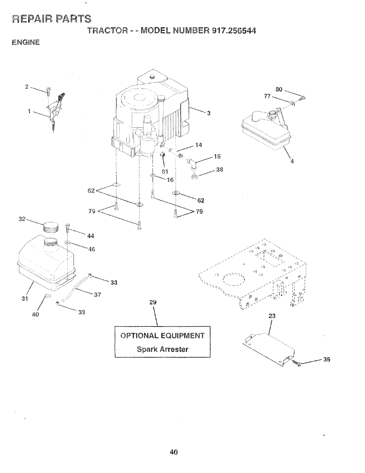
REPAIR PARTS
TRACTOR o o MODEL NUMBER 917.256544
ENGmNE
I
l
44
33
OPTIONAL EQUIPMENT
Spark Arrester
4
23
35
4O
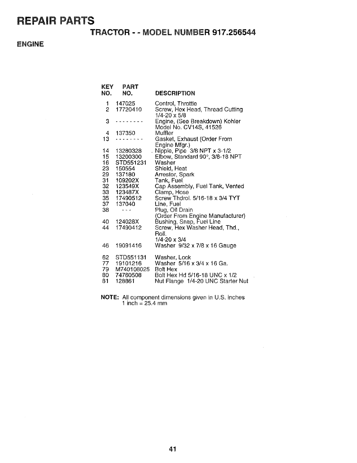
REPAIR PARTS
TRACTOR -° MODEL NUMBER 917.256544
ENGINE
KEY PART
NO, NO. DESCRIPTION
147025
17720410
4 137350
13 ........
14 13280328
15 13200300
16 STD551231
23 150554
29 137180
31 109202X
32 123549X
33 123487X
35 17490512
37 137040
38 --_
40 124028X
44 17490412
46 19091416
82 STD551131
77 191O1216
79 M740!08025
80 74760508
81 128861
Control, Throttle
Screw, Hex Head, Thread Cutting
1/4-20 x 5/8
Engine, (See Breakdown) KoNer
Model No. CV14S, 41526
Muffler
Gasket, Exhaust (Order From
Engine Mfgr.)
.Nipple, Pipe 3/8 NPT x 3-1/2
Elbow, Standard 90°, 3/8-18 NPT
Washer
Shield, Heat
Arrestor, Spark
Tank, Fuel
Cap Assembly, Fuel Tank, Vented
Clamp, Hose
Screw ThdroL 5/16-18 x 3/4 TYT
Line, Fuel
Plug, Oil Drain
(Order From Engine Manufacturer)
Bushing, Snap, Fue! Line
Screw, Hex Washer Head, Thd.,
Roll.
1/4-20 x 3/4
Washer 9/32 x 7/8 × 18 Gauge
Washer, Lock
Washer 5/16 x 3/4 x 16 Ga.
Bolt Hex
Bolt Hex Hd 5/16-18 UNC x 1/2
Nut Flange 1/4-20 UNC Starter Nut
NOTE: All component dimensions given in U.S. inches
1 inch = 25.4 mm
41
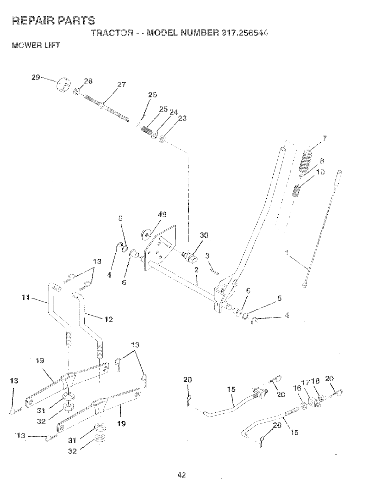
REPAIR. PARTS
TRACTOR - ° MODEL NU_IBER 917o256544
_aOWER LIFT
26
25 24
/
13
46
13
t9
19
13
49
30
3
\
2
i
J
/ /
/
/<
i
/ ,
i
/
1/
/
/ /
1i
J/
/i
20 .,_,'h
,J_:>)[ r20
-, C.V1;S;.%. ........
42
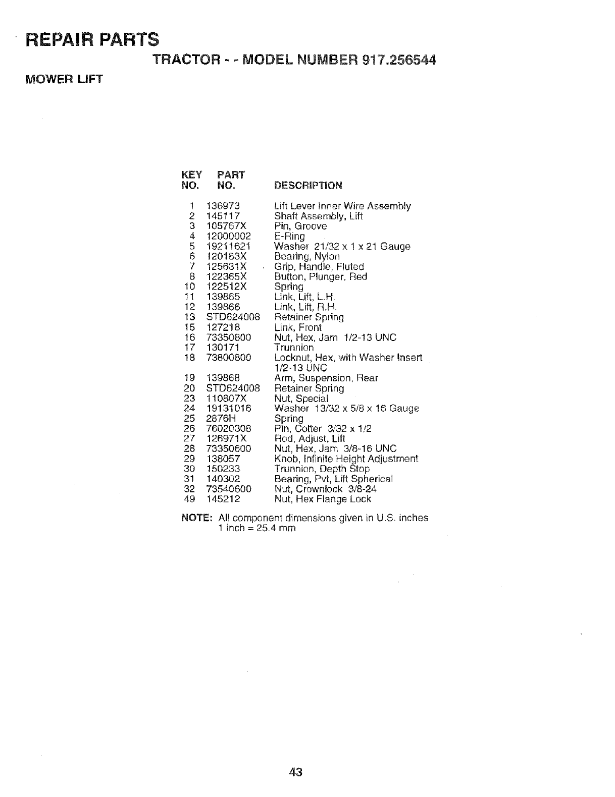
REPAIR PARTS
TRACTOR - - MODEL NUMBER 917.256544
MOWER LIFT
KEY PART
NO, NO, DESCRIPTION
1 136973
2 145117
3105767X
4 120ooo02
5 19211621
6 120183X
7 125631X
8 122365X
10 122512X
11 139865
12 139866
13 STD624008
15 127218
16 73350800
17 130171
18 73800800
19 139868
2O STD624008
23 110807X
24 19131016
25 2876H
26 76020308
27 126971X
28 73350600
29 138057
30 150233
31 140302
32 73540600
49 145212
Lift Lever Inner Wire Assembly
Shaft Assembly, Lift
Pin, Groove
E-Ring
Washer 21/32 x 1 x 21 Gauge
Bearing, Nylon
Grip, Handle, Fluted
Button, Plunger Red
Spring
Link, Lift, L.H.
Link, Lift, R.H.
Retainer Spring
Link, Front
Nut, Hex, Jam !/2-13 UNC
Trunnion
Locknut, Hex, with Washer Insert
1/2o13 UNC
Arm, Suspension, Rear
Retainer Spring
Nut, Special
Washer 13/32 x 5i8 × 16 Gauge
Spring
Pin, Cotter 3/32 x 1/2
Rod, Adjust, Lift
Nut, Hex, Jam 3/8-16 UNC
Knob, infinite Height Adjustment
Trunnion, Depth Stop
Bearing, Pvt, Lift Spherical
Nut, Crownlock 3/8-24
Nut, Hex Flange Lock
NOTE: Al! component dimensions given in U.S. inches
1 inch = 25.4 mm
43
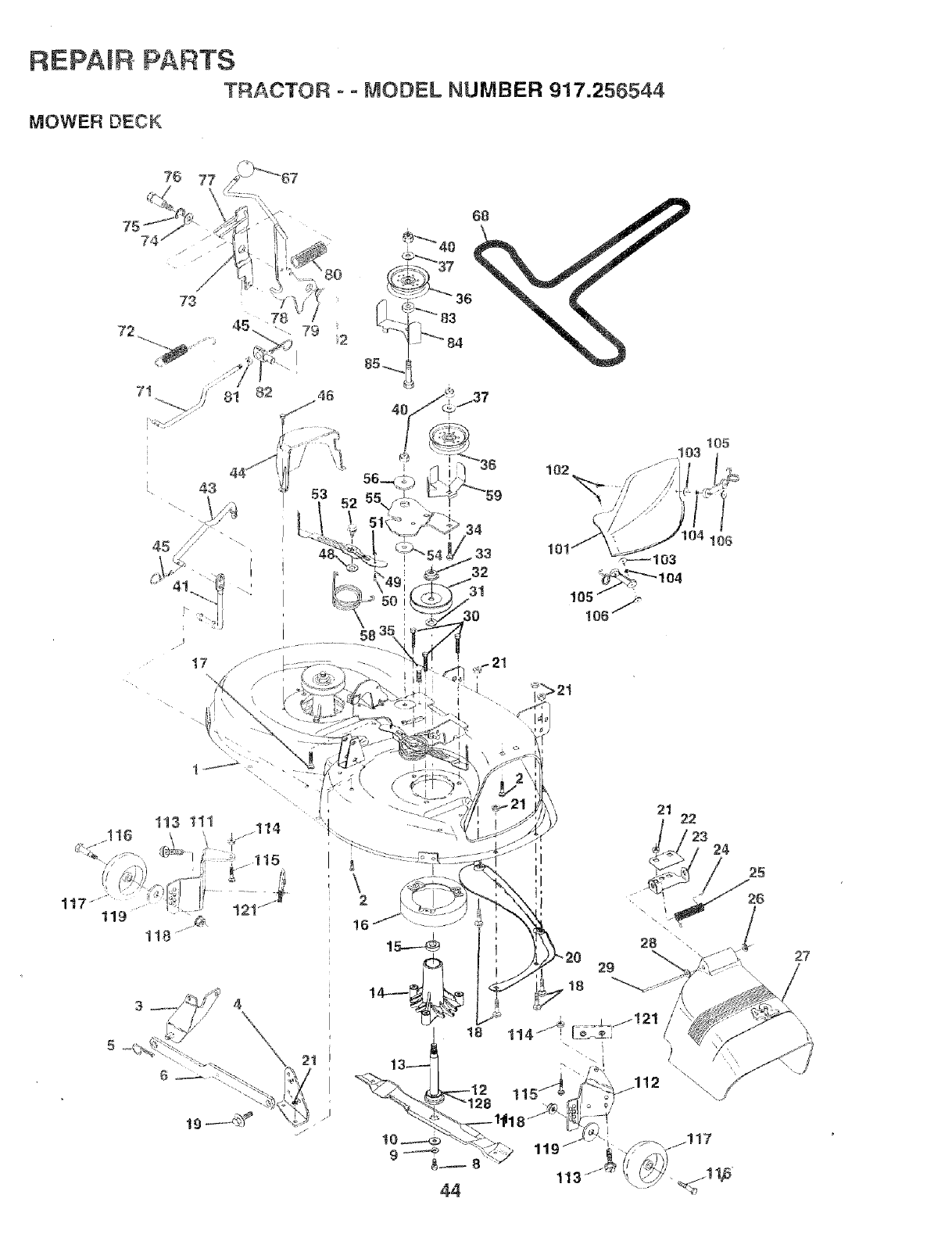
REPAIR PARTS
TRACTOR o - MODEL NUMBER 917.256544
MOWER DECK
74
81 82
34
33
32
3O
102
105
17
113 tll
16
1t7" t19 118
3 ....... /_-_.7// 4
// °X
\ 2t
......-_, !,7
j-
21 22
23 24
25
119
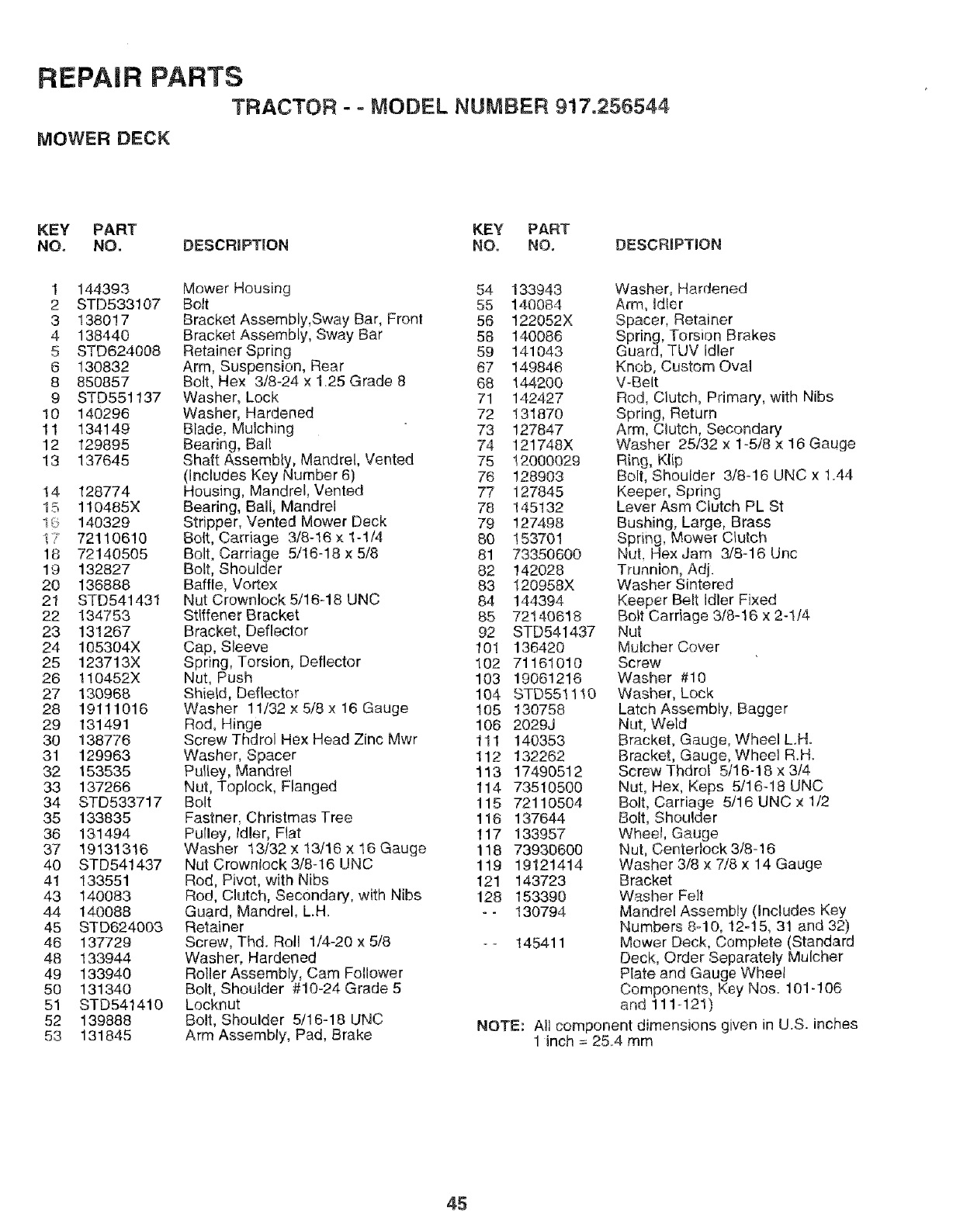
REPAIR PARTS
TRACTOR --MODEL NUMBER 917.256544
MOWER DECK
KEY PART KEY PART
NO. NO. DESCR_PTION NO. NO. DESCRBPTION
1 144393
2 STD533107
3 138017
4 138440
5 STD624008
6 130832
8 850857
9 STD551137
10 140296
11 134149
12 129895
13 137645
14 128774
15 110485X
1G 140329
1T 72110610
18 72140505
19 132827
20 136888
21 STD541431
22 134753
23 131267
24 105304X
25 123713X
26 1!0452X
27 130968
28 19111016
29 131491
30 138776
31 129963
32 153535
33 137266
34 STD533717
35 133835
36 131494
37 19131316
40 STD541437
41 133551
43 140083
44 140088
45 STD624003
46 137729
48 133944
49 133940
50 131340
51 STD541410
52 139888
53 131845
Mower Housing 54 133943
Bolt 55 140084
Bracket Assembly,Sway Bar, Front 56 122052X
Bracket Assembly, Sway Bar 58 140086
Retainer Spring 59 141043
Arm, Suspension, Rear 67 149846
Bolt, Hex 3/8-24 x 125 Grade 8 68 144200
Washer, Lock 71 142427
Washer, Hardened 72 131870
Blade, Mulching 73 127847
Bearing, Ball 74 121748X
Shaft Assembly, Mandrel, Vented 75 12000029
(includes Key Number 6) 76 128903
Housing, Mandrel, Vented 77 127845
Bearing, Ball, Mandrel 78 145132
Stripper, Vented Mower Deck 79 127498
Bolt, Carriage 3/8-16 x 1-1/4 60 153701
Bolt, Carriage 5/16-18 x 5/8 81 73350600
Bolt, Shoulder 82 142028
Baffle, Vortex 83 120958X
Nut Crownlock 5/16d8 UNC 84 144394
Stiffener Bracket 85 72t40618
Bracket, Deflector 92 STD541437
Cap, Sleeve 101 136420
Spring, Torsion, Deflector 102 71161010
Nut, Push 103 19061216
Shield, Deflector 104 STD551110
Washer 11/32 x 5/8 x 16 Gauge 105 130758
Rod, Hinge 108 2029J
Screw Thdrol Hex Head Zinc Mwr 1I 1 140353
Washer, Spacer 112 132262
Pulley, Mandrel 113 17490512
Nut, Toplock, Flanged 114 73510500
Bolt 115 72110504
Fastner, Christmas Tree 116 137644
Pulley, Idler, Fiat 117 133957
Washer 13/32 x 13/16 x 16 Gauge 118 73930600
Nut Crowniock3/8-16 UNC 119 19121414
Rod, Pivot, with Nibs 121 143723
Rod, Clutch, Secondary, with Nibs 128 153390
Guard, Mandrel, L.H. - -130794
Retainer
Screw, Thd. Roll 1/4-20 x 5/8 -- 145411
Washer, Hardened
Roller Assembly, Cam Follower
Bolt, Shouider #10-24 Grade 5
Locknut
Bolt, Shoulder 5/16-18 UNC
Arm Assembly, Pad, Brake
Washer, Hardened
Arm, idler
Spacer, Retainer
Spring, Torsion Brakes
Guard, TUV idler
Knob, Custom Oval
V-Belt
Rod, Clutch, Pdmary, with Nibs
Spring, Return
Arm, Clutch, Secondary
Washer 25/32 x 1-5/8 x 16 Gauge
Ring, Klip
Bolt, Shoulder 3/8q 6 UNC x 1.44
Keeper, Spring
Lever Asm Clutch PL St
Bushing, Large, Brass
Spring, Mower Clutch
Nut, Hex Jam 3/8-16 Uric
Trunnion, Adj.
Washer Sintered
Keeper Belt idler Fixed
Bolt Carriage 3/8-16 x 2-1/4
Nut
Mulcher Cover
Screw
Washer #10
Washer, Lock
Latch Assembly, Bagger
Nut, Weld
Bracket, Gauge, Wheel L.H.
Bracket, Gauge, Wheel R.H.
Screw Thdrol 5/16-18 x 3/4
Nut, Hex, Keps 5/16-18 UNC
Bolt, Carriage 5/16 UNC x 1/2
Bolt, Shoulder
Wheel, Gauge
Nut, Centertock 3/8-16
Washer 3/8 x 7/8 x 14 Gauge
Bracket
Washer Felt
Mandrel Assembly (Includes Key
Numbers 8-10, 12-15, 31 and 32)
Mower Deck, Complete (Standard
Deck, Order Separately Mulcher
Plate and Gauge Wheel
Components, Key Nos. 101-106
and 111-121)
NOTE: All component dimensions given in U.S. inches
1inch = 2&4 mm
45
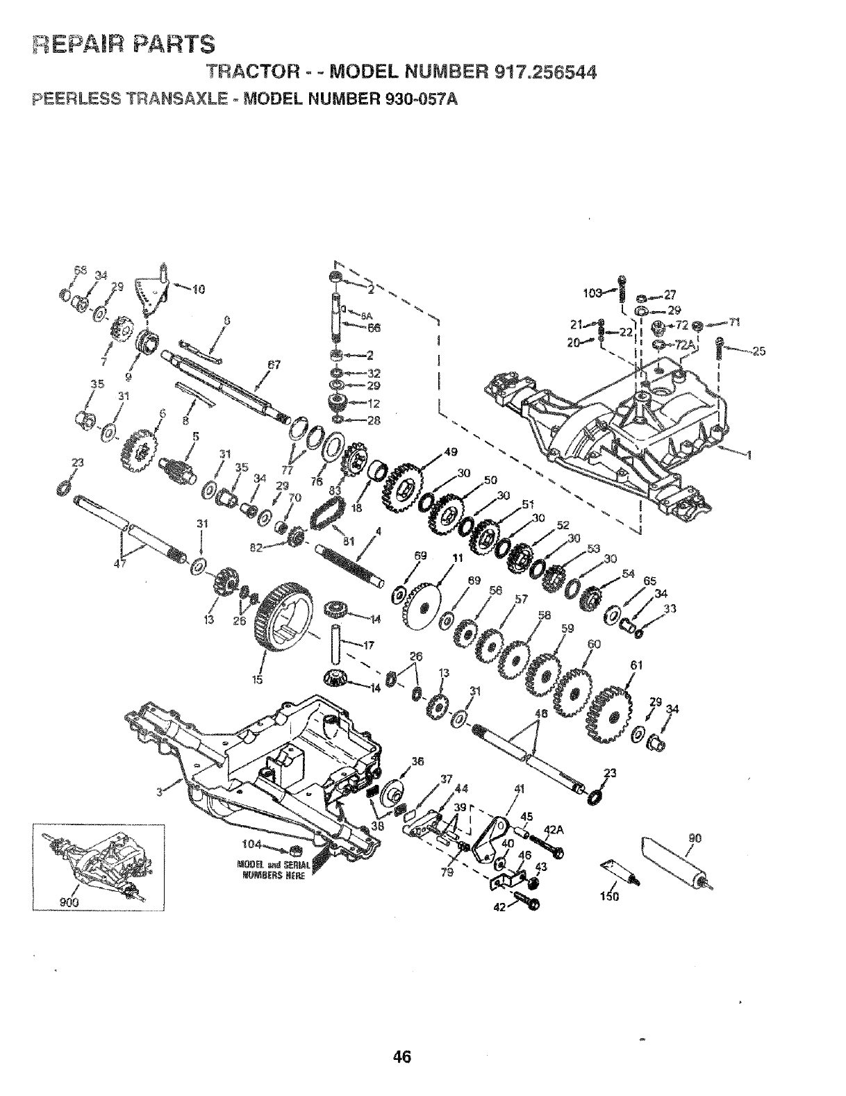
F_EPA)R PARTS
TRACTOR °- MODEL NUMBER 917.256544
PEERLESS TRANSAXLE = MODEL NUMBER 930-057A
t5
900
45
42A
23
90
/
46
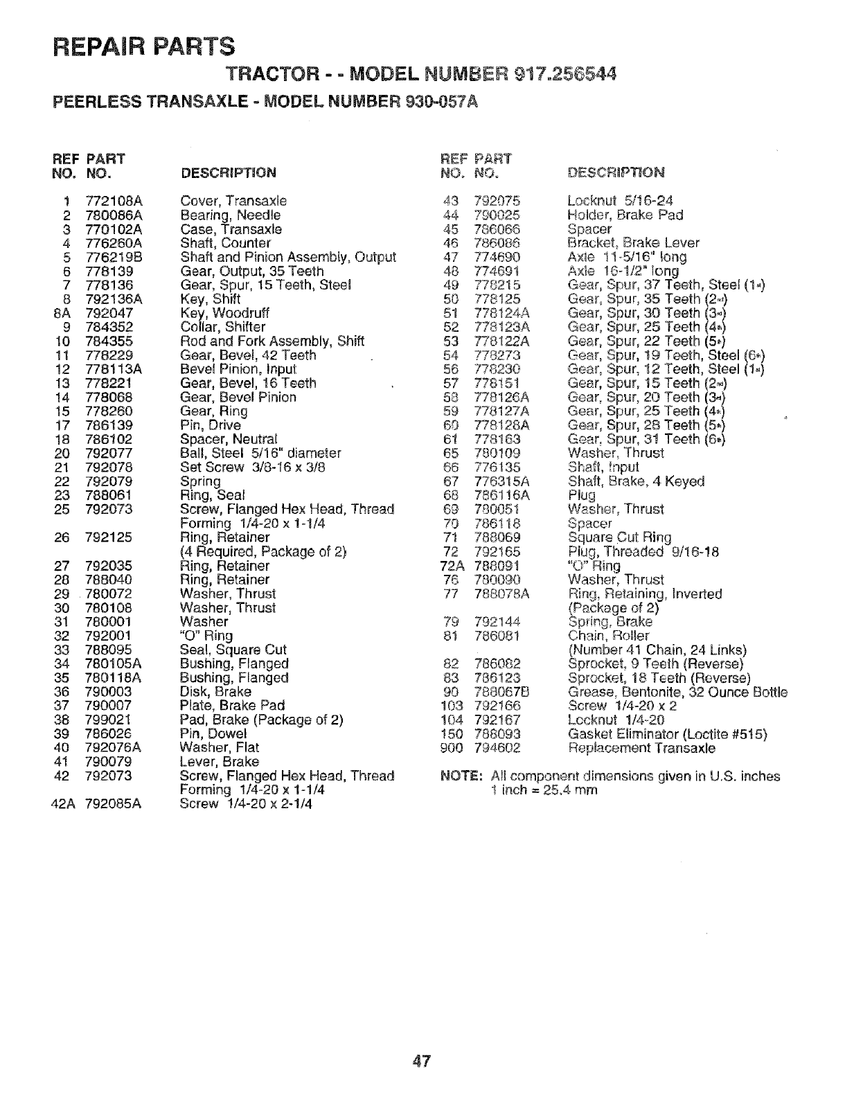
REPAIR PARTS
TRACTOR - = MODEL NUMBER 917o256544
PEERLESS TRANSAXLE = MODEL NUMBER 930-057A
REF PART REF PART
NO. NO. DESCRIPTION N©o NO. DESCRIPTION
1 772108A Cover, Transa×le 43 792075
2 780088A Bearing, Needle 44 790025
3 770102A Case, Transaxle 45 786066
4 776260A Shaft, Counter 46 786086
5 776219B Shaft and Pinion Assembly, Output 47 774690
6 778139 Gear, Output, 35Teeth 48 774691
7 778!36 Gear, Spur, 15 Teeth, Steet 49 778215
8 792136A Key, Shift 50 778125
77812_A
8A 792047 Key, Woodruff 5! _.
9 784352 Collar, Shifter 52 778123A
10 784355 Rod and Fork Assembly, Shift 53 778122A
11 778229 Gear, Bevel, 42 Teeth 54 778273
12 778113A Bevel Pinion, input 56 778230
13 778221 Gear, Bevel. 16 Teeth 57 778"151
14 778068 Gear, Bevel Pinion 58 778126A
15 778260 Gear, Ring 59 778127A
17 786t39 Pin, Drive 60 778128A
18 786102 Spacer, Neutral 6! 778163
20 792077 Ball, Steel 5/16" diameter 65 780109
21 792078 Set Screw 3/8-16 x 3/8 66 776135
22 792079 Spring 67 776315A
23 788061 Ring, Seal 68 786116A
25 792073 Screw, Flanged Hex Head, Thread 69 780051
Forming 1/4-20 x 1-1/4 70 786118
28 792125 Ring, Retainer 71 788069
(4 Required, Package of 2) 72 792165
27 792035 Ring, Retainer 72A 788091
28 788040 Ring, Retainer 76 780090
29 780072 Washer, Thrust 77 788078A
30 780108 Washer, Thrust
31 780001 Washer 79 792144
32 792001 "O" Ring 81 786081
33 788095 Seal, Square Cut
34 780105A Bushing, Flanged 82 786082
35 780118A Bushing, Flanged 83 786123
36 790003 Disk, Brake 90 788067B
37 790007 Plate, Brake Pad 103 792166
38 799021 Pad, Brake (Package of 2) t04 792167
39 786026 Pin, Dowel 150 788093
40 792076A Washer, Flat 900 794602
41 790079 Lever, Brake
42 792073 Screw, Flanged Hex Head, Thread
Forming 1/4o20 x 1-1/4
42A 792085A Screw 1/4-20 x 2-1/4
Locknut 5/16-24
Holder, Brake Pad
Spacer
Bracket Brake Lever
A×ie !1-5/16" long
Axle 10-1/2" long
Gear Spur, 37 Teeth, Steel (1°,)
Gear Spur, 35
Gear Spur, 30
Gear Spur, 25
Gear Spur, 22
Gear t9
Spur,
Gear Spur, 12
Gear Spur, 15
Gear Spur, 20
Gear Spur, 25
Gear, Spur, 28
Teeth (2,-)
Teeth (3_)
Teeth (44)
Teeth (5.)
Teeth, Steel (6.)
Teeth, Steel (1.)
Teeth (2.,)
Teeth (3-)
Teeth (4_)
Teeth (5,)
Gear, Spur, 3! Teeth (6.)
Washer, Thrust
Shaft, !nput
Shaft, Brake, 4 Keyed
Plug
Washer, Thrust
Spacer
Square Cut Ring
Plug, Threaded 9/16-!8
"O" Ring
Washer, Thrust
Ring, Retaining, Inverted
(Package of 2)
Spring, Brake
Chain, Roller
(Number 41 Chain, 24 Links)
Sprocket, 9 Teeth (Reverse)
Sprocket, 18 Teeth (Reverse)
Grease, Bentonite, 32 Ounce Bottle
Screw 1/4-20 x 2
Locknut 1/4_20
Gasket Eliminator (Loctite #5t5)
Replacement Transaxle
NOTE: All component dimensions given in U.S. inches
1 inch = 25A mm
47
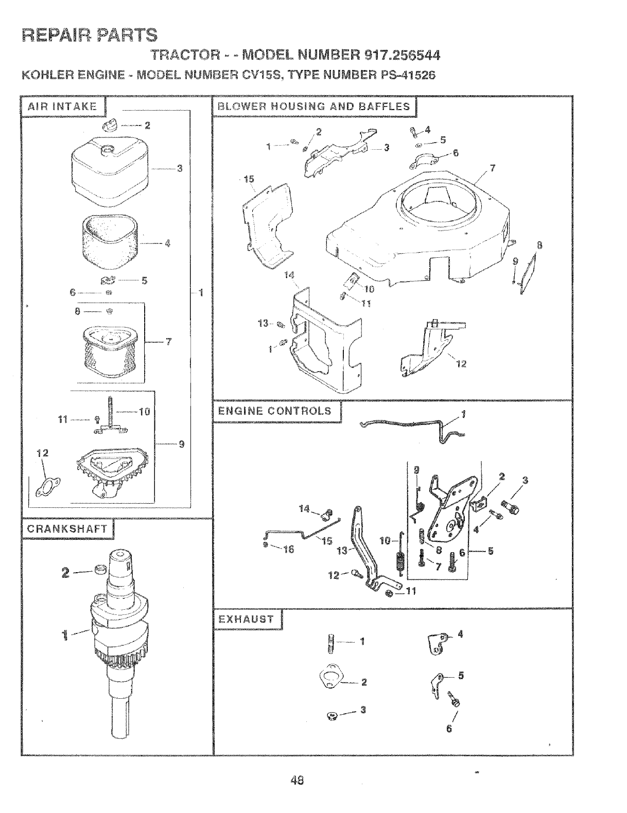
REPA B PA£TS
TRACTOR - ° MODEL NUMBER 917o256544
KOHLER ENGINE o MODEL NUMBER CV15S_ TYPE NUB_IBER PS-41526
12
__7 ¸
_ANKSNAFT [
' Q .... N_
BL..WER HOUS_
_4
15 /7
14
/
6
48
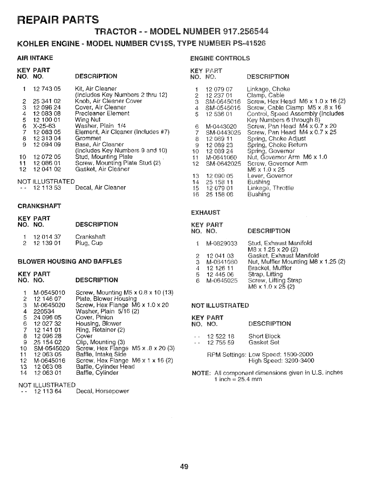
REPAIR PARTS
TRACTOR -- MODEL NUMBER 917.256544
KOHLER ENGINE - MODEL NUMBER CV15S, TYPE NUMBER PS-41526
AIR iNTAKE ENGINE CONTROLS
KEY PART KEY PART
NO. NO. DESCRiPTiON NOD NO DESCRIPTION
12 743 05
2 25 341 02
3 12 096 24
4 12 083 08
5 1210001
6 X-25-63
7 12 083 05
8 12 313 04
9 12 094 09
10 12 072 05
11 1208601
12 12 041 02
Kit, Air Cleaner 1
(includes Key Numbers 2 thru !2) 2
Knob, Air Cleaner Cover 3
Cover, Air Cleaner 4
Precleaner Element 5
Wing Nut
Washer, Plain 1/4 6 M-0443020
Element, Air Cleaner (includes #7} 7 SM=0443025
Grommet 8 12 089 11
Base, Air Cleaner 9 12 089 23
(Includes Key Numbers 9 and 10) 10 12 089 24
Stud, Mounting Plate . 11 M-0641060
Screw, Mounting Plate Stud (2) 12 SM_0642025
Gasket, Air Cleaner
NOT ILLUSTRATED
- - 12 113 53 Decal, Air Cleaner
CRANKSHAFT
KEY PART
NO. NO. DESCRIPTION
1 12 014 37 Crankshaft
2 12 139 01 Plug, Cup
BLOWER HOUSING AND BAFFLES
KEY PART
NO. NO. DESCRIPTION
1 M-0545010
2 12 146 O7
3 M-0645020
4 220534
5 24 096 05
6 12 027 32
7 12 14! 01
8 12 096 28
925 154 02
10 SM-0545020
11 12 063 05
12 M-0645016
13 12 063 08
14 12 063 01
Screw, Mounting M5 x 0.8 x 10 (13)
Plate, Blower Housing
Screw, Hex Flange M6 x 1.0 x 20
Washer, Plain 5/16 (2)
Cover, Pinion
Housing, Blower
Ring, Retainer (2)
Cover
Clip, Mounting (3)
Screw, Hex Flange M5 x .8 x 20 (3)
Baffle, intake Side
Screw, Hex Flange M6 x I x 16 (2)
Baffle, Cylinder Head
Baffle, Cylinder
NOT ILLUSTRATED
- - 12 113 64 Decal, Horsepower
!2 079 07
12 237 01
SMO645016
SM-0545016
12 536 01
13 12 090 05
14 25 t58 11
15 t2 079 0!
16 25 158 08
Linkage, Choke
Clamp, Cable
Screw, Rex Head M6 x 1.0 x 16 (2)
Screw, Cable Clamp M5 x .8 x 16
Control, Speed Assembly (includes
Key Numbers 6 through 8)
Screw, Pan Head M4 x 0.7 x 20
Screw, Pan Head M4 x 0.7 x 25
Spring, Choke Adjust
Spring, Choke Return
Spring, Governor
Nut, Governor Arm M6 x 1.0
Sere'w, Governor Arm
M6 x 1.0 x 25
[ever, Governor
Bushing
[inkage, Throttle
Bushing
EXHAUST
KEY PART
NO. NOD
1 M-0829033
2 12 041 03
3 M-0841080
4 12 126 11
5 12 445 06
6 M-0645025
DESCRIPTION
Stud, Exhaust Manifold
M8 x 1.25 x 20 (2)
Gasket, Exhaust Manifold
Nut, Muffler Mounting M8 x 1.25 (2)
Bracket, Muffler
Strap, Lifting
Screw, Lifting Strap
M6 x 1.0 x 25 (2)
NOTILLUSTRATED
KEY PART
NO. NO,
-- 12 522 18
-- 12 755 59
DESCRIPTION
Short Block
Gasket Set
RPM Settings: Low Speed: 1500-2000
High Speed: 3200-3400
NOTE: AIJcomponent dimensions given in U.S. inches
1 inch = 25.4 mm
49
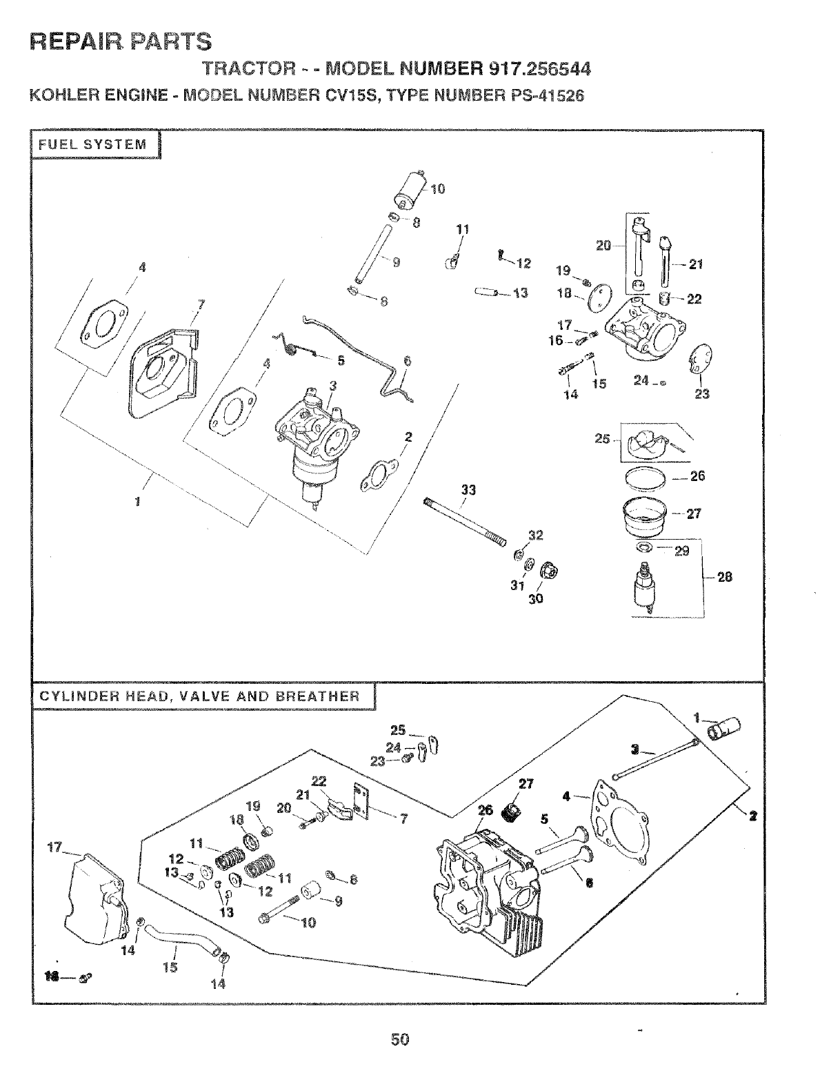
REPAmR PARTS
TRACTOR - = MODEL NUMBER 917.256544
KOHLER ENGINE oMODEL NUMBER CV15S, TYPE NUMBER PS-4!526
FUEL SYSTEM
/
/
/
/
11
/
/
/
/
0 ....
19
18-._
24 __ I
23
--26
-27
'_5-_-- 29 I
......................
t7
19 20
/8 \
/.____.__//
5O
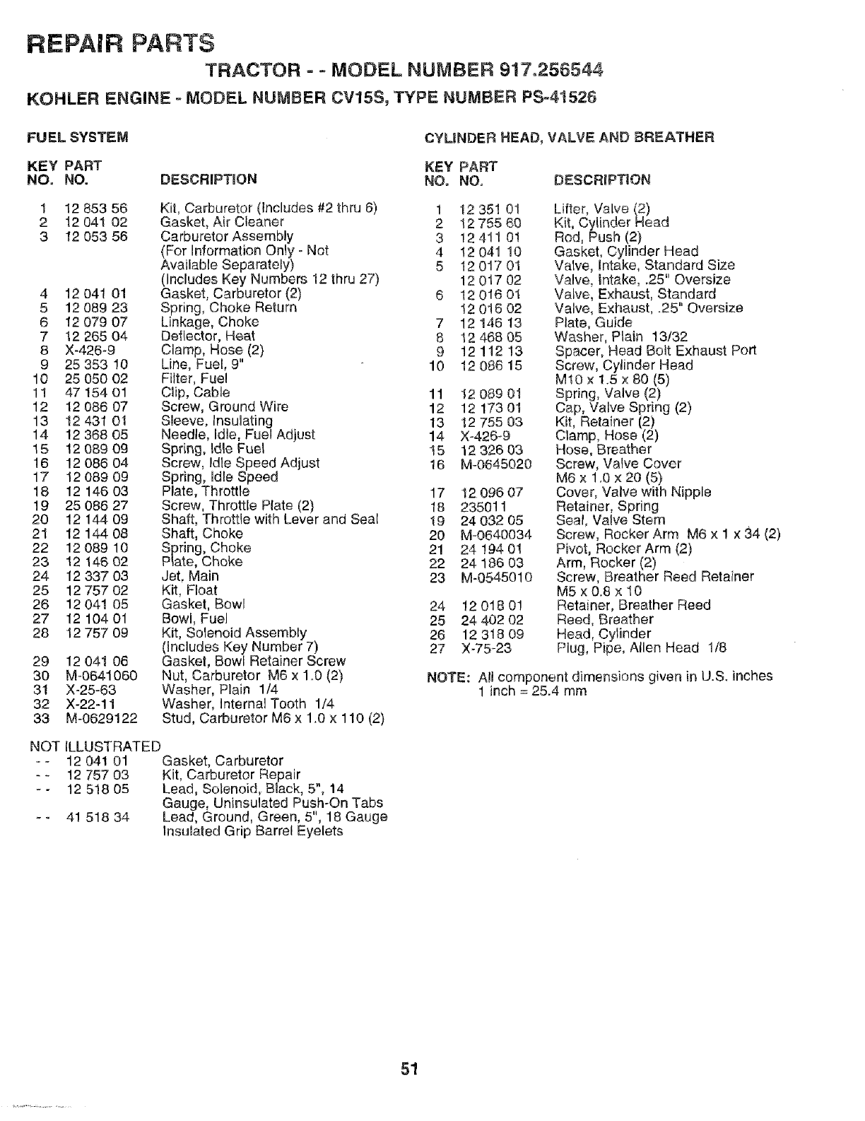
REPAIR PARTS
TRACTOR - = MODEL NUMBER 917.256544
KOHLER ENGINE =MODEL NUMBER CV15S, TYPE NUMBER PS-41526
FU EL SYSTEM CYMNDER HEAD, VALVE AND BREATHER
KEY PART KEY PART
NO, NO. DESCRIPTION NO, NO, DESCRWPTION
1 12 853 56
2 12 041 02
3 12 053 56
4 12 041 01
5 12 089 23
612 079 07
7 12 265 O4
8 X-426°9
9 25 353 10
10 25 O5OO2
1! 47 154 01
12 12 086 07
13 12 431 01
14 12 368 O5
15 12 089 09
16 12 086 04
17 12 089 09
18 12 146 03
19 25 086 27
20 12 144 09
21 12 144 08
22 12 089 10
23 12 146 02
24 12 337 03
25 12 757 O2
26 12 041 05
27 12 104 01
28 12 757 09
Kit, Carburetor (Includes #2 thru 6) 1 12 35! 0t
Gasket, Air Cleaner 2 12 755 60
Carburetor Assembly 3 12 411 01
(For Information Only- Not 4 12 041 10
Available Separately) 5 12 017 01
(includes Key Numbers 12 thru 27) 12 0t7 02
Gasket, Carburetor (2) 6 12 016 01
Spring, Choke Return 12 016 02
Linkage, Choke 7 12 146 13
Deflector, Heat 8 12 468 05
Clamp, Hose (2) 9 1211213
Line, Fuel, 9" 10 12 086 15
Filter, Fuel
Clip, Cable 11
Screw, Ground Wire 12
Sleeve, Insulating 13
Needle, idle, Fuel Adjust 14
Spring, Idle Fuel 15
Screw, Idle Speed Adjust 16
Spring, Idle Speed
Plate, Throttle 17
Screw, Throttle Plate (2) 18
Shaft, Throttle with Lever and Seal 19
Shaft, Choke 20
Spring, Choke 21
P_ate, Choke 22
Jet, Main 23
Kit, Float
Gasket, Bowl 24
Bowl, Fuel 25
Kit, Solenoid Assembly 26
(Includes Key Number 7) 27
Gasket, Bowl Retainer Screw
Nut, Carburetor M6 x 1.0 (2)
Washer, Plain 1/4
Washer, Internal Tooth 1/4
Stud, Carburetor M6 x 1.0 x 110 (2)
29 12 041 06
30 M-0641060
31 X-25-63
32 X-22-11
33 M-0629122
NO-[ ILLUSTRATED
-- 12 041 01 Gasket, Carburetor
-- 12 757 03 Kit, Carburetor Repair
= - 12 518 05 Lead, Solenoid, B_ack, 5", 14
Gauge, Uninsulated Push-On Tabs
- - 41 518 34 Lead, Ground, Green, 5", 18 Gauge
Insulated Grip Barrel Eyelets
12 089 01
12 173 01
12 755 03
X-426_9
12 326 03
M-0645020
12 096 07
235011
24 032 05
M-0640034
24 194 01
24 186 03
M-0545010
12 018 01
24 402 02
12 318 09
X-75-23
Lifter, Valve (2)
Kit, Cylinder Head
Rod, Push (2)
Gasket, Cylinder Head
Valve, Intake, Standard Size
Valve, _ntake, .25" Oversize
Valve, Exhaust, Standard
Valve, Exhaust, _25" Oversize
Plate, Guide
Washer, Plain 13/32
Spacer, Head Bolt Exhaust Port
Screw, Cylinder Head
Mr0 x 1.5 x 80 (5)
Spring, Valve (2)
Cap, Valve Spring (2)
Kit, Retainer (2)
Clamp, Hose (2)
Hose, Breather
Screw, Valve Cover
M6 x 1.0 x 20 (5)
Cover, Valve with Nipple
Retainer, Spring
Seal, Valve Stem
Screw, Rocker Arm M6 x 1 x 34 (2)
Pivot, Rocker Arm (2)
Arm, Rocker (2)
Screw, Breather Reed Retainer
MSx0.8 x 10
Retainer, Breather Reed
Reed, Breather
Head, Cylinder
Plug, Pipe, Allen Head 1/8
NOTE: All component dimensions given in U.S. inches
1 inch = 25.4 mm
51
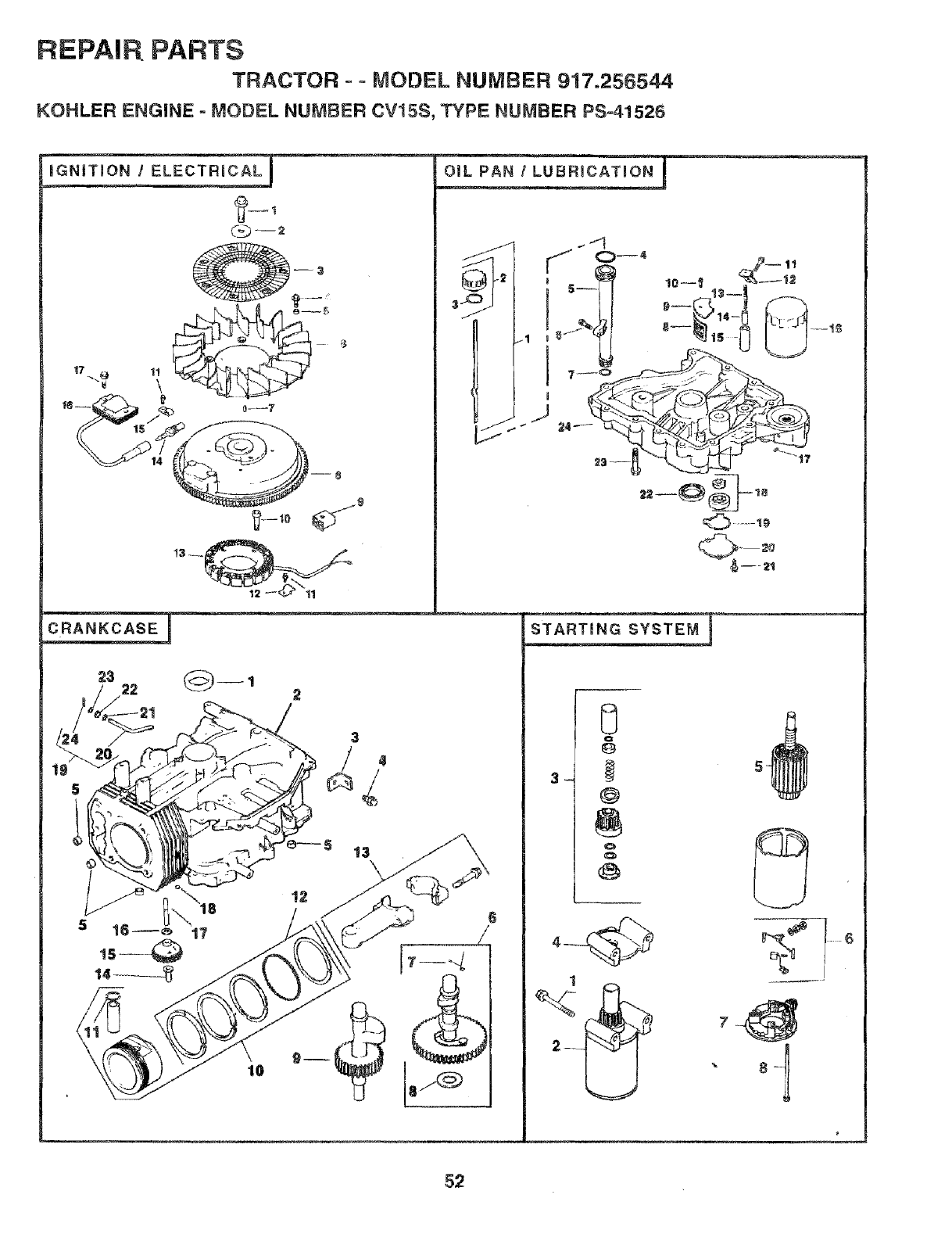
REPAI P!PARTS
TRACTOR o- MODEL NUMBER 917.256544
KOHLER ENGINE - MODEL NUMBER CV15$, TYPE NUMBER PS°41525
23
°-9 lI_
J
--- 21
3
1
5_
i
_ 8- !
52
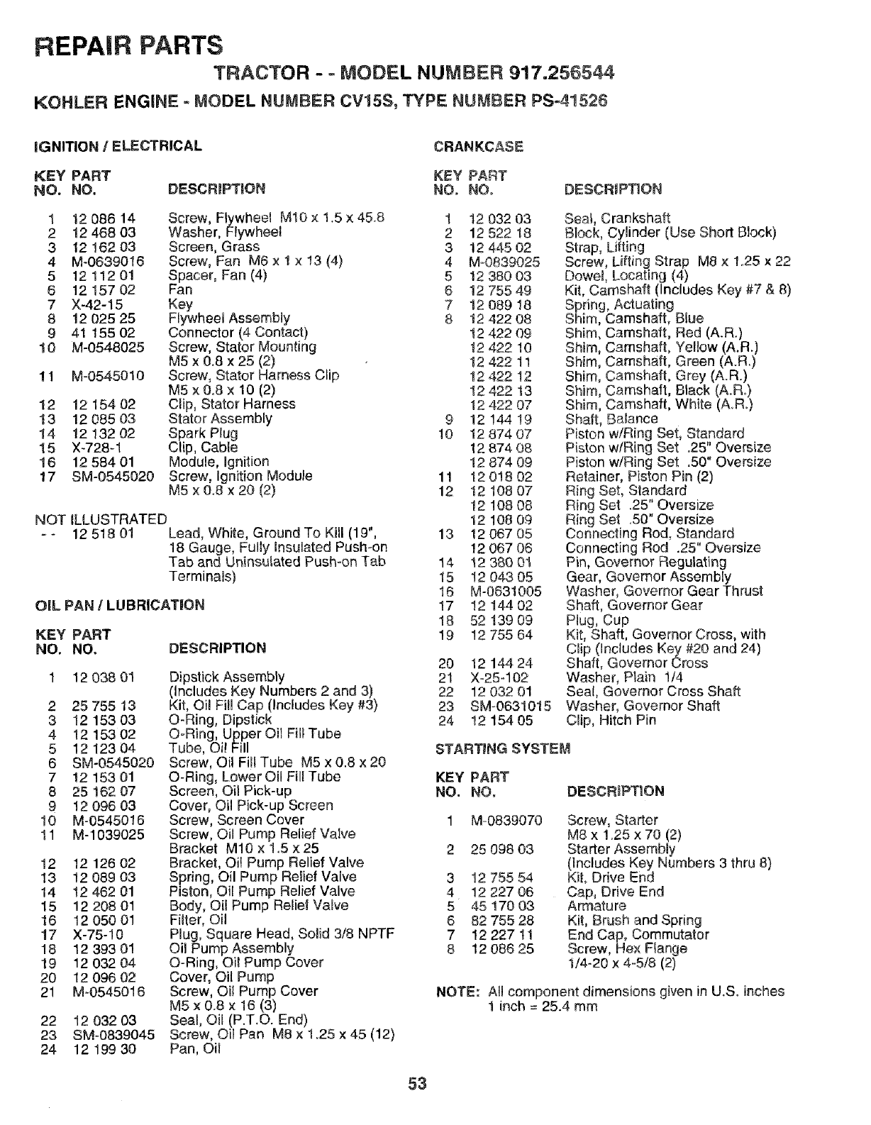
REPAIR PARTS
TRACTOR - ° MODEL NUMBER 917.256544
KOHLER ENGINE - MODEL NUMBER CV15S, TYPE NUMBER PS-41526
iGNITION /ELECTRICAL CRANKCASE
KEY PART KEY PART
NO. NO, DESCRIPT!ON NO. NO, DESCRIP_ON
DESCRIPTION
1 12 086 14 Screw, Flywheel M10 x 1.5 × 45.8 1 12 032 03
2!2 468 03 Washer, Flywheel 2 12 522 18
3 12 !62 03 Screen, Grass 3 12 445 02
4 M-0639016 Screw, Fan M6 x 1 x 13 (4) 4 M-0839025
5 1211201 Spacer, Fan (4) 5 1238003
6 12 157 02 Fan 6 12 755 49
7 X-42-15 Key 7 !2 089 18
8 12 025 25 Flywheel Assembly 8 t2 422 08
9 4! 155 02 Connector (4 Contact) !2 422 09
10 M-0548025 Screw, Stator Mounting t2 422 10
M5 x 0.8 x 25 (2) 12 422 11
11 M-0545010 Screw, Stator Harness Clip 12 422 !2
M5 x 0.8 x 10 (2) 12 422 t3
12 12 154 02 Clip, Stator Harness 12 422 07
13 12 085 03 StatorAssembly 9 12 !44 !9
14 12 132 02 Spark Plug 10 12 874 07
15 X-728-1 Clip, Cable 12 874 08
16 12 584 01 Module, Ignition 12 874 09
17 SM-0545020 Screw, Ignition Module 11 12 018 02
M5x0.8x20(2) 12 12 108 07
12 108 08
NOT _LLUSTRATED 12 108 09
- - 12 518 01 Lead, White, Ground To Kill (19", 13 12 067 05
18 Gauge, Fully Insulated Push-on 12 067 06
Tab and Uninsu_ated Push-on Tab 14 12 380 01
Terminals) 15 12 043 05
16 M-0631005
OIL PAN /LUBRICATION 17 12 144 02
18 52 !39 09
KEY PART 19 1275564
NO. NO.
12 038 01
2 25 755 13
3 12 153 03
4 12 153 02
5 12 123 04
6 SM-0545020
7 12 153 01
8 25 162 07
9 12 096 03
10 M-0545016
11 M-1039025
12 12 126 02
13 12 089 03
14 12 462 01
15 12 2O8 01
16 12 050 01
17 X-75-10
18 12 393 01
19 12 032 04
20 12 096 02
21 M-0545018
Dipstick Assembly
(Includes Key Numbers 2 and 3)
Kit, Oil Fill Cap (Includes Key #3)
O-Ring, Dipstick
O-Ring, Upper Oil Fil{ Tube
Tube, Oi! Fill
Screw, Oil Fill Tube M5 x 0.8 x 20
O-Ring, Lower Oil Fill Tube
Screen, Oil Pick-up
Cover, Oil Pick-up Screen
Screw, Screen Cover
Screw, Oil Pump Relief Valve
Bracket M10 x 1.5 ×25
Bracket, Oil Pump Relief Valve
Spring, Oil Pump Relief Valve
Piston, Oil Pump Relief Valve
Body, Oil Pump Relief Valve
Filter, Oil
Plug, Square Head, Solid 3/8 NPTF
Oil Pump Assembly
O-Ring, Oi_ Pump Cover
Cover, OilPump
Screw, Oil Pump Cover
M5 x 0.8 x 16 (3)
Sea!, Oil (P.T.O. End)
Screw, Oil Pan M8 x 1.25 x 45 (12)
Pan, Oil
22 12 032 03
23 SM-0839045
24 12 199 3O
20 12 144 24
21 X-25-102
22 12 032 01
23 BM-0631015
24 12 154 05
Seal, Crankshaft
Block, Cylinder (Use Short Block)
Strap, Lifting
Screw, Lifting Strap M8 x 1.25 x 22
Dowel, Locating (4)
Kit, Camshaft (Includes Key #7 & 8)
Spring, Actuating
Shim, Camshaft, Blue
Shim, Camshaft, Red (A.R.)
Shim, Camshaft, Yellow (A.R.)
Shim, Camshaft, Green (A.R.)
Shim, Camshaft, Grey (A.R.)
Shim, Camshaft, Black (A.R.)
Shim, Camshaft, White (A.R.)
Shaft, Balance
Piston w/Ring Set, Standard
Piston wiRing Set .25" Oversize
Piston w/Ring Set .50" Oversize
Retainer, Piston Pin (2)
Ring Set, Standard
Ring Set .25" Oversize
Ring Set .50" Oversize
Connecting Rod, Standard
Connecting Rod .25" Oversize
Pin, Governor Regulating
Gear, Governor Assembly
Washer, Governor Gear Thrust
Shaft, Governor Gear
Hug, Cup
Kit, Shaft, Governor Cross, with
Clip (Includes Key #20 and 24)
Shaft, Governor Cross
Washer, Plain 1t4
Seal, Governor Cross Shaft
Washer, Governor Shaft
Clip, Hitch Pin
STARTING SYSTEM
KEY PART
NO. NO. DESCRiPTiON
3
4
5
6
7
8
M-0839070
25 098 03
12 755 54
!2 227 06
45 170 03
82 755 28
12 227 tl
12 086 25
Screw, Starter
M8 x 1.25 x 70 (2)
Starter Assembly
(Includes Key Numbers 3 thru 8)
KiL Drive End
Cap, Drive End
Armature
Kit, Brush and Spring
End Cap, Commutator
Screw, Hex Flange
1/4-20 x 4-5/8 (2)
NOTE: All component dimensions given in U.So inches
1inch = 25.4 mm
53

CE NOTES
54

SUGGESTED GUIDE FOR SiGHTiNG SLOPES FOR SAFE OPERATION
T
SIGHTING "" _.
ONLY RiDE UP AND DOWN HILL,
NOT ACROSS HiLL
SIGHT AND HOLD THIS LEVEL WITH
SKY LINE OR TREE.
15° MAX.
t _ Operate your Tractor up and down the face of slopes (not
I
greater than 15°), never across the face. Make turns gradu- I
ally to prevent tipping or loss of control. Exercise extreme
caution when changing direction on slopes.

'S
MANUAL
MODEL NO.
917.256544
IF YOU NEED
REPAIR SERVICE
OR PARTS:
FOR REPAIR SERVICE, CALL
THIS TOLL FREE NUMBER:
1-800-4-REPAIR
(1-800-473-7247)
FOR REPLACEMENT PARTS
INFORMATION AND
ORDERING, CALL THIS
TOLL FREE NUMBER:
1-800-FON-PART
(1-800-366-7278)
FOR CONSUMER ASSISTANCE
HOT LINE, CALL THIS
TOLL FREE NUMBER:
1-800-659-5917
®
15.0 HP
ELECTRIC START
42" MOWER
6SPEED TRANSAXLE
LAWN TRACTOR
Each tractor has its own model number. Each engine has
its own model number.
The model number for your tractor wilI be found on the
model plate located under the seat.
The model number for your engine will be found on the
blower housing of the engine.
All parts Iisted herein may be ordered from any Sears,
Roebuck and Co. Service Center/Department and most Re-
tail Stores.
WHEN ORDERING REPAIR PARTS, ALWAYS GIVE THE
FOLLOWING INFORMATION:
•PRODUCT- TRACTOR
•MODEL NUMBER - 917.256544
•ENGINE MODEL NO. -0V15S-41526
•PART NUMBER
PART DESCRIPTION
Your Sears merchandise has added value when you
consider Sears has service units nationwide staffed with
Sears trained technicians.., professional technicians
specifically trained to insure that we meet our pledge to
you, we service what we sell.
155155 Rev. 3 10.3.96 JH/KFSW/JH Printed in U.S.A.
