Craftsman 917 258911 Users Manual
917258911 917258911 CRAFTSMAN TRACTOR - Manuals and Guides L0909447 View the owners manual for your CRAFTSMAN TRACTOR #917258911. Home:Lawn & Garden Parts:Craftsman Parts:Craftsman TRACTOR Manual
CRAFTSMAN Lawn, Tractor Manual L0909447 CRAFTSMAN Lawn, Tractor Owner's Manual, CRAFTSMAN Lawn, Tractor installation guides
917.258911 L0909447
2015-01-05
: Craftsman Craftsman-917-258911-Users-Manual-160818 craftsman-917-258911-users-manual-160818 craftsman pdf
Open the PDF directly: View PDF ![]() .
.
Page Count: 60

MODEL NUMBER 917.258911
®
OWNER'S MANUAL
oAssembly
° Operation
° Customer Responsibilities
° Service and Adjustments
° Repair Parts
CAUTION: Read and follow all safety rules and instructions before operating this equipment.
FOR CONSUMER ASSISTANCE HOT LINE, CALL THIS TOLL FREE NUMBEI_. 1-800-659-5917
.................................... , ,H, , ,,,H,,,,, iltltlllll tt tttttttttttt Illilllllilliililiilllllli
SAFETY RULES
Safe Operation Practices for Ride-On Mowers
IMPORTANT: THIS CUTTING MACHINE IS CAPABLE OF AMPUTATING HANDS AND FEET AND THROWING OBJECTS,_
FAILURE TO OBSERVE THE FOLLOWING SAFETY INSTRUCTIONS COULD RESULT IN SERIOUS INJURY OR DEATH.
i. GENERAL OPERATION
.Read, understand, and follow all instructionsin the manual
and on the machine before starting
•Only allow responsible adults, who are familiar with the
instructions,to operate the machine,.
•Clear the area of objects such as rocks, toys, wire, etc.
which could be picked up and thrown by the blade.
III. CHILDREN
Tragic accidents can occur ifthe operator is not alert to the
presence of children. Children are often attracted to the
machine and the mowing activity_ Never" assume that
children will remain where you last saw them,
. Besure the area isclear of otherpeople before mowing_ Stop
machtne ifanyone enters the area.
•Never carry passengers..
° Do not mow inreverse unless absolutely necessary. Always
look down and behind before and while backing
°Be aware of the mower discharge direction and do not point
it at anyone. Do not operate the mower witt_out either the
entire grass catcher or the guard in place..
• Slow down before turning._
• Never leave a running machine unattended, Always turn off
blades, set parking brake, stop engine, and remove keys
before dismounting
•Turn off blades when not mowing..
•Stop engine before removing grass catcher or unclogging
chute.
• Mow only in daylight or good artificial lighL
° Do not operate the machine while under the influence of
alcohol or drugs.
•Watch for traffic when operating near or crossing roadways.
•Use extra care when loading or unloading the machine into
a trailer or truck.
IL SLOPE OPERATION
Slopes are a major factor related to toss-of-control and
tipover accidents, which can result in severe injury ordeath,
All slopes require extra caution. If you cannot back up the
slope or if you feel uneasy on it, do not mow it..
DO:
•Mow up and down slopes, not across.
•Remove obstacles such as recks, tree limbs, etc.,
•Watch for holes, ruts, or bumps. Uneven terrain could
overturn the machine_ Taftgrass can hide obstacles.
• Use slow speed. Choose a lowgear so that you willnot have
to stop or shift while on the slope.
•Follow the manufacturer's recommendations for' wheel
weights or counterweights to improve stability,
°Use extra care with grass catchers or other attachments..
These can change the stability of the machine
• Keep all movement on the slopes sfowand gradual,. Do not
make sudden changes in speed or direction.
• Avoid starting or stopping on a siope_ if tires lose traction,
disengage the blades and proceed slowly straight down the
slope.
•Keep children out of the mowing area and under the watchful
care of another- responsible adulL
° Be alert and turn machine off if children enter the area°
•Before and when backing, look behind and down for small
children.
,, Never carry children. They may fall off and be seriously
injuredor interferewith safe machine operation.
•Never allow children to operate the machine
• Use extra care when approaching blind corners, shrubs,
trees, or other objects that may obscure vision.
IVk
°
o
°
e
o
o
SERVICE
Useextra care inhandling gasoline andother fuels. They are
flammable and vapors are explosive,
Use only an approved container,
Never remove gas cap or add fuel with the engine
running. Allow engine to coo! before refueling Do not
smoke,.
Never' refuel the machine indoors.
Never store the machine or fuel container inside where
there is an open fEame,such as a water heater,
Never run a machine inside a closed area_
Keep nuts and bolts, especialiy blade attachment bolts, tight
and keep equipment in good condition
Never tamper with safety devices.. Check their proper
operation regularly,.
Keep machine free of grass, leaves, or other debris build-up,
Clean oil or fuel spillage, Allow machine to cool before
storing_
Stop and inspect the equipment if you strike an object
Repair, if necessary, before restarting.
Never make adjustments or repairs with the engine running.
Grass catcher components are subject to wear, damage, and
deterioration, which could expose moving pads or allow
objects to be thrown, Frequently check components and
replace with manufacturer's recommended parts, when nec-
essary_
Mower' blades are sharp and can cut. Wrap the blade(s) or
wear gloves, and use extra caution when servicing them.
Check brake operation frequently Adjust and service as
required.
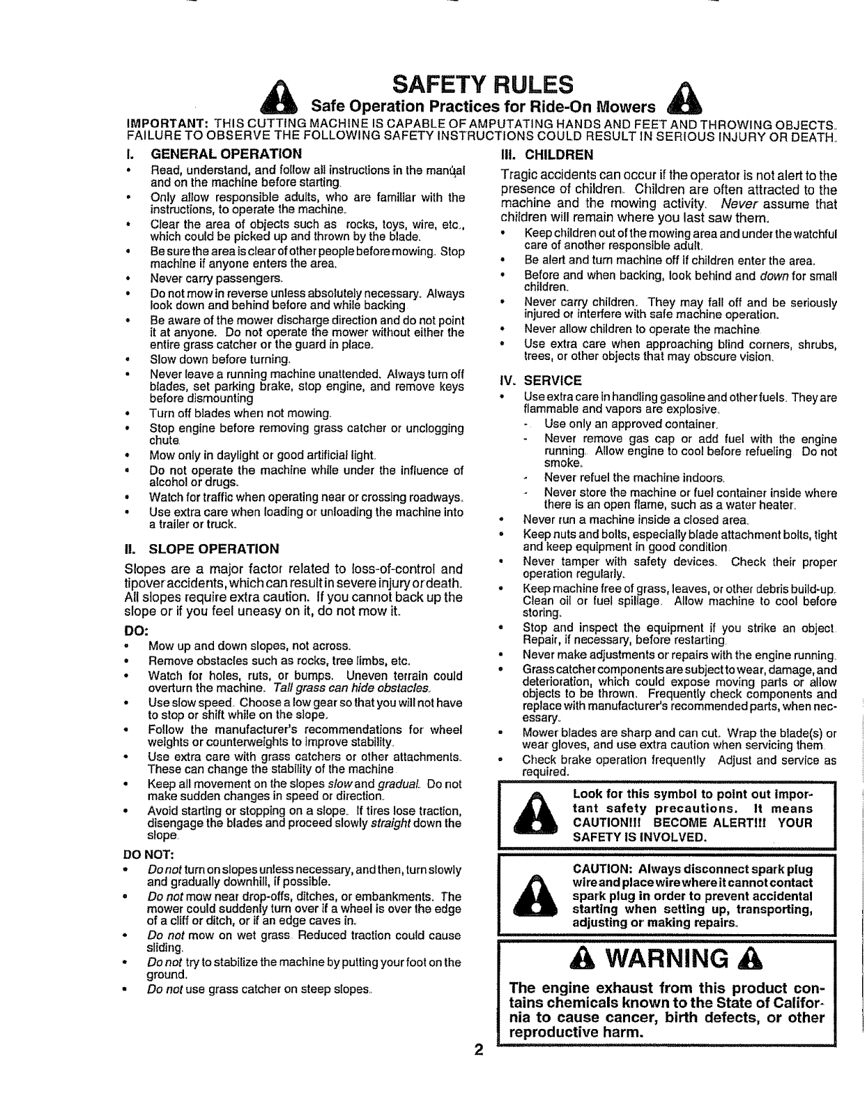
Look for' this symbol to point out impor- .........i
tant safety precautions. It means I
CAUTIONII! BECOME ALERTIII YOUR
SAFETY IS iNVOLVED.
DO NOT:
•Do not turn on slopes unIessnecessary, and then, turnslowly
and gradually downhill, if possible.
.Do not mow near drop-offs, ditches, or embankments. The
mower could suddenly turn over if a wheel is over the edge
of a cliff or ditch, or if an edge caves in,,
•Do not mow on wet grass Reduced traction could cause
sliding
•Do not tryto stabilize the machine by puttingyour foot on the
ground.
•Do not use grass catcher on steep slopes..
2
I -- CAUTION: Always disconnect spark plug I
I_=_ wire and placewire whereit cannot contact I
I_spark plug in order to prevent accidental I
i_starting when setting up, transporting, I
I adjusting or makin.g,,.,repatrso . .,. !
,A WARNING
The engine exhaust from this product con-
tains chemicals known to the State of Califor-
nia to cause cancer, birth defects, or other
reproductive harm.

CONGRATULATIONS on your purchase of a Sears
Tractor° It has been designed, engineered and manufac-
tured to give you the best possible dependability and
performance.
Should you experience any problem you cannot easily
remedy, please contact your nearest Sears Authorized
Service Center/Department Department. We have com-
petent, well-trained technicians and the proper tools to
service or repair this tractor.
Please read and retain this manual.. The instructionswill
enable you to assemble and maintain your tractorpropefly.
Always observe the "SAFETY RULES".
MODEL
NUMBER 917.258911
SERIAL
qUMBER
DATE OF PURCHASE
THE MODEL AND SERIAL N UMBERS WILL BE FOUND
ON A PLATE UNDER THE SEAT_
YOU SHOULD RECORD BOTH SERIAL NUMBER AND
DATE OF PURCHASE AND KEEP IN A SAFE PLACE
FOR FUTURE REFERENCE.
MAINTENANCE AGREEMENT
A Sears Maintenance Agreement is available on this prod-
uct. Contact your nearest Sears store for details.
CUSTOMER RESPONSIBILITIES
o Read and observe the safety rules.
° Follow a regular schedule inmaintaining, caring for and
using your tractor.
° Follow the instructions under "Customer Responsibili-
ties" and "Storage" sections of this owner's manual,.
PRODUCT SPECIFICATIONS
HORSEPOWER: 22.5
GASOLINE CAPACITY 3.5 GALLONS
AND TYPE: UNLEADED REGULAR
OIL TYPE (API-SF/SG/SH): SAE 10W30 (above 32°F)
SAE 5W-30 (below 32°F)
OIL CAPACITY: W/FILTER: 42 PINTS
WTO FILTER: 37 PINTS
SPARK PLUG: CHAMPION RC12YC
(GAP: _030")
VALVE CLEARANCE: NOT ADJUSTABLE
GROUND SPEED (MPH): FORWARD: 0 - 58
REVERSE: 0-2.t
TIRE PRESSURE: FRONT: 14 PSI
REAR: 10 PSI
CHARGING SYSTEM: 15 AMPS @ 3600 RPM
BATTERY: AMP/HR: 35
M1N CCA: 280
CASE SIZE: U1R
BLADE BOLT TORQUE: 30-35 FT. LBS
WARNING: This tractor is equipped with an internal
combustion engine and should not be used on or near any
unimproved forest-covered, brush-coverer] or grass-cov-
ered land unlessthe engine's exhaust system is equipped
with a spark arrestor meeting applicable local or state laws
(if any)_ ifa spark arrester is used, it should be maintained
in effective working order by the operator.
In the state of California the above is required by law
(Section 4442 of the California Public Resources Code)..
Other states may have similar lawso Federal laws apply on
federal lands. A spark arrester for the muffler is available
through your nearest Sears Authorized Service Center/
Department (See REPAIR PARTS section of this manual).
,, ,, ,,,,,,,,,,,,,,,,,,,,,,,,, ...................................................................
LIMITED "iNVOYEAR WARRANTY ON CRAFTSMAN RIDING EQUIPMENT
For two (2) years from the date of purchase, if this Craftsman Riding Equipment is maintained, lubricated and tuned up according
to the instructions in the owner's manual, Sears will repair or replace, free of charge, any parts found to be defective in material
or workmanship.
This Warranty does not cover:
• Expendable items which become wom during normal use, such as blades, spark plugs, air cleaners, belts, etc.
•Tire replacement or repair caused by punctures from outside objects, such as nails, thorns, stumps, or glass_
• Repairs necessary because of operator abuse, negligence, improper storage or accident or the failure to maintain the
equipment according to the instructions contained in the owner's manual
• Hidingequipment used for commercial or rental purposes.
LIMITED 90 DAY WARRANTY ON BATTERY
For ninety (90) days from date of purchase, if any battery included with this riding equipment proves defective in material or
workmanship and our testing determines the battery wifenot hold a charge, Sears will replace the battery at no charge.
IN-HOME WARRANTY SERVICE ON YOUR CRAFTSMAN HIDING EQUIPMENT IS AVAILABLE AT NO-CHARGE FOR 30
DAYS FROM THE DATE OF PURCHASE. PLEASE CONTACT YOUR NEAREST SERVICE CENTER.. AFTER 30 DAYS
FROM THE DATE OF PURCHASE, WARRANT'( SERVICE IS AVAILABLE BY TAKING YOUR CRAFTSMAN RIDING EQUIP-
MENT TO YOUR NEAREST SEARS SERVICE CENTER. (IN-HOME WARRANTY SERVICE WILL STILL BE AVAILABLE
AFTER 30 DAYS FROM THE DATE OF PURCHASE BUT A STANDARD TRIP CHARGE WILL APPLY..) THIS WARRANTY
APPLIES ONLY WHILE THIS PRODUCT IS IN THE UNITED STATES_
This Warranty gives you specific legal rights, and you may also have other rightswhich may vary from state to state.
SEARS, ROEBUCK AND CO., [:)/817 WA, HOFFMAN ESTATES, IL 60179
.............................................................. ,, ,,,, ,,,,,,i
3
SAFE'P/' RULES ............................................................ 2
PRODUCT SPECIFICATIONS ...................................... 3
CUSTOMER RESPONSIBILITIES ..................... 3, 16-19
WARRANTY ..................................................................3
TRACTOR ACCESSORIES ..................................... 5,15
ASSEMBLY .............................................................. 7-10
OPERATION ........................................................... 12-16
MAINTENANCE SCHEDULE ......................................17
SERVICE AND ADJUSTMENTS ............................ 21-27
STORAGE ................................................................... 28
TROUBLESHOOTING ............................................ 29-30
REPAIR PARTS _TRACTOR ................................. 32-50
REPAIR PARTS - ENGINE .................................... 51-58
PARTS ORDERING/SERVICE ................ BACK COVER
iNDEX A
Accessories ............................................................5
Adjustments;
Brake ...............................................................23
Carburetor'. .................................................27
Clutch Pulley .......................................23
Gauge Wheels .................................14
Mower'
Front-To-Back ....................................22
Side-To-Side ................................2!
Throttle Control Cable ............................27
Air Filter, Engine ............................................20
Air Screen, Engine ...........................................19
Assembly ....................................................7-10
B
Battery:
Charging .............'o.................................8
Cleaning ..............................................20
Stading with Weak Battery .................25
Storage ............................................28
Terminals .........................................................19
Belt:
Motion Drive
Removal/Replacement ............ 24
Mower Ddve
RemovaVReplacement .................22
Mower Blade Drive
RemovaVReplacement ..............23
Blade:
Sharpening ...........................................18
Replacement ....................................................18
Brake Adjustment .............................................23
C
Carburetor Adjustment .......................... 27
Clutch Pulley ...........................................23
Controls, Tractor .................................................12
Customer Responsibilities ......................17-20
Engine:
Air Filter ..............................................20
Air Screen .....................................19
Cooling Fins .............................................20
Engine OtI ....................................15,19
Fuel Filter ..........................................20
Spark Plug(s) .................................20
Tractor:
Battery ...................................................18
Blade ................................................18
Lubrication Chart ..............................17
Maintenance Schedule ................17
Tire Care .....................................8,18,25
Transaxle .........................................19
Cutting Height, Mower ........................... t3
E
Electrical:
Interlocksand Relays ...............................26
Schematic ....................................................31
Winng Diagram .......................................32
Engine:
Air Filter...............................................20
Air Screen ..........................................19
Cooling Fins ...........................................20
Oil Change .....................................................19
Oil Level ............................................15
Oil Type ...........................................15,19
Preparation .......................................................15
Repair Pads ............................. 51-58
Starling .................................................15-16
Storage ....................................................28
F
Filter:
Air Filter .............................................20
Fuel ........................................................20
Oil......................................................................20
Fuel:
Storage .......................................... 28
Type ...................................................................15
Fuse ....................................................................26
H
Headtfghts .............................................................26
Hood Removalltnstaflation ......................26
L
LeveIfng Mower Deck ..............................22
Lubrication:
Chart ...........................................................17
Engine .............................................................t9
M
Maintenance Schedule .....................................17
Mower:
Adjustment, Front4mBack .............22
Adjustment, Side4o-Side .....................21
Blade Replacement ...........................18
Blade Sharpening ............................18
Cutting Height ............................................13
installation .............................................21
Operation ............................................14
Removal ...................................................21
Mowing Tips ....................................................16
Muffler ................................................................20
Spark ArresteL .................................3,40
Oil:
O
Cold Weather Conditions ......... 15,t9
Engine ......................................................................t9
Storage .................................................28
4
Operation ...........................................................t2-16
Operating Mower. .............................................14
Options:
Accessories .............................................5
Spark Arrester ........................................3,40
P
Parking Brake ............................................................13
Parts Bag ........................................................6
Parts, Replacement/Repair ....................32-50
Product Specifications ...................................3
R
Repair Parts ....................................................32-50
S
Safety Rules .......................................................2
Seat .........................................................................8
Service and Adjustments ....................21-27
Carburetor'. .........................................................27
Clutch Pulley ..........................................23
Fuse .....................................................26
Hood RemovaVlnstallation ........... 26
Motion Drive Belt
Removal/Replacement ..............22
Mower' Drive Belt
RemovaVReplacement .....................22
Mower Blade Drive Belt
RemovaVReplacement ............ 23
Mower' Adjustment
Front4o-Back ...........................................22
Side-to-Side ................................21
Mower RemovaVlnstallation ............21
Tire Care .......................................8,16,25
Slope Guide Sheet ..........................................59
Spark Plug(s) ............................................20
Specifications ...........................................................3
Starling the Engine ..............................15-16
Steering Wheel .................................................7,24
Stopping the Tractor ..............................................13
Storage .........................................................................28
T
Throttle Control Cable Adjustment ........27
Tires ................................................ 8,18,25
Troubleshooting Chart ...........................29-30
Transaxle ................................................................19
W
Warranty ...............................................................3
Wiring Diagram ..........................................32
Wiring Schematic .......................................31
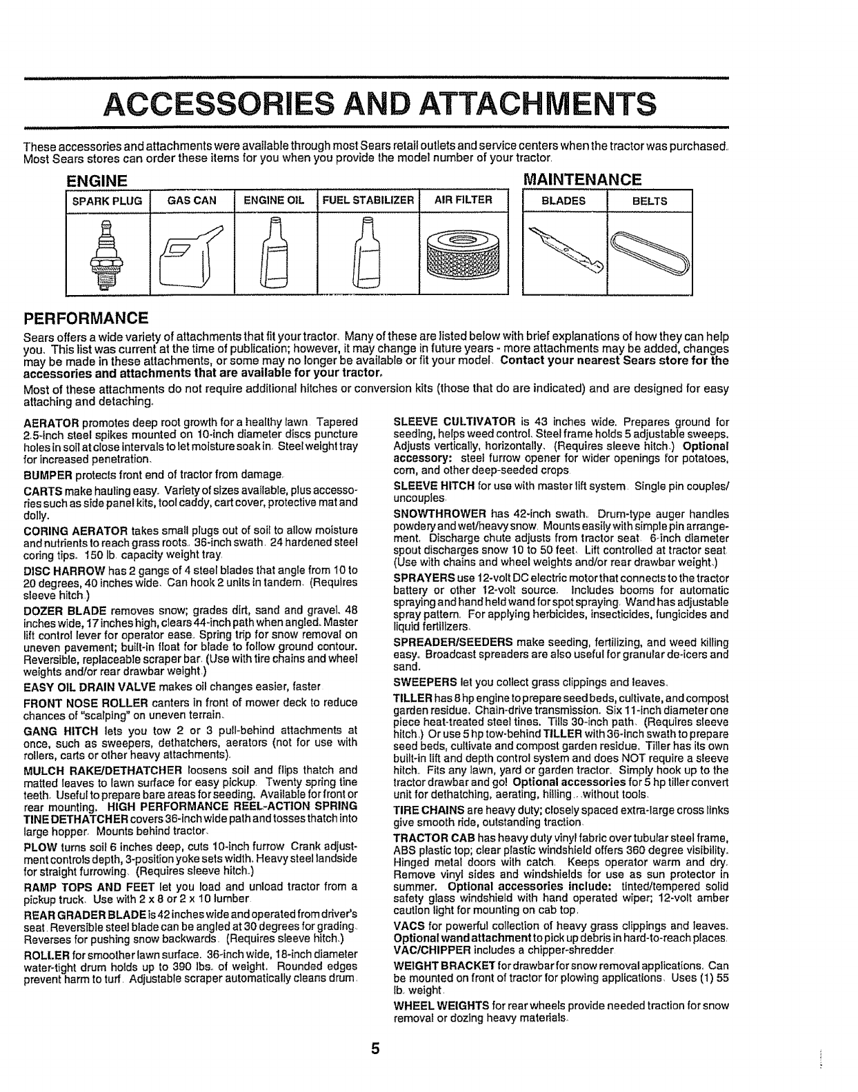
ACC iES AND ATTACHMENTS
These accessories and attachments were available through most Sears retail outlets and service centers when the tractor was purchased,,
Most Sears stores can order these items for you when you provide the model number of your tractor,
ENGINE MAINTENANCE
BLADES BELTSSPARK PLUG GAS CAN ENGINE OIL : FUEL STABILIZER AIR FILTER
PERFORMANCE
Sears offersa widevarietyofattachmentsthatfit yourtractor.Manyofthesearelistedbelowwithbriefexplanationsof howtheycanhelp
you, This list was current at the time of publication; however, it may change in 1uture years - more attachments may be added, changes
may be made in these attachments, or some may no longer be available or fit your model. Contact your nearest Sears store for the
accessories and attachments that are available for your tractor,
Most of these attachments do not require additional hitches or conversion kits (those that do are indicated) and are designed for easy
attaching and detaching°
AERATOR promotes deep root growth for a healthy lawn Tapered
2,5qnch steel spikes mounted on lO-inch diameter discs puncture
holes in soil at close Intervals to let moisture soak in, Steel weight tray
for increased penetration,
BUMPER protects front end of tractor from damage,
CARTS make hauling easy° Variety of sizes available, plus accesso-
ries such as side panel kits, tool caddy, cart cover, protective mat and
dolly.
GORING AERATOR takes small plugs out of soil to allow moisture
and nutrients to reach grass roots_,36-inch swath. 24 hardened steel
coring tips, 150 lb. capacity weight tray
DISC HARROW has 2 gangs of 4 steel blades that angle from 10 to
20 degrees, 40 inches wide, Can hook 2 units in tandem, (Requires
sleeve hitch)
DOZER BLADE removes snow; grades dirt, sand and gravel 48
inches wide, 17 inches high, clears 44-inch path when angled, Master
lift control lever for operator ease_, Spring trip for snow removal on
uneven pavement; built-in float for blade to follow ground contour.
Reversible, replaceable scraper bar, (Use with tire chains and wheel
weights andlor rear drawbar weight,)
EASY OIL DRAIN VALVE makes oil changes easier, faster
FRONT NOSE ROLLER canters in front of mower deck to reduce
chances of "scalping" on uneven terrain_
GANG HITCH lets you tow 2 or 3 pull-behind attachments at
once, such as sweepers, dethatchers, aerators (not for use with
rollers, carts or other heavy attachments).
MULCH RAKE/DETHATCHER loosens soil and flips thatch and
matted leaves to lawn surface for easy pickup. Twenty spring tine
teeth, Useful to prepare bare areas for seeding, Available for front or
rear mounting. HIGH PERFORMANCE REEL-ACTION SPRING
TINE DETHATCHER covers 36-inch wide path and tosses thatch into
large hopper, Mounts behind tractor,
PLOW turns soil 6inches deep, cuts 10-inch furrow Crank adjust-
ment controls depth, 3-position yoke sets width, Heavy steel landside
for straight furrowing.. (Requires sleeve hitch.,)
RAMP TOPS AND FEET let you load and unload tractor from a
pickup truck, Use with 2 x 8 or 2 x 10 lumber
REAR GRADER BLADE is 42 inches wide and operated from driver's
seat, Reversible steel blade can be angled at 30 degrees for grading,
Reverses for pushing snow backwards, (Requires sleeve hitch,)
ROLLER for smoolhertawnsurface. 36-inchwide, 18-inch diameter
water-tight drum holds up to 390 ]bs,, of weight. Rounded edges
prevent harm to turf. Adjustable scraper automatically cleans drum,
SLEEVE CULTIVATOR is 43 inches wide. Prepares ground for
seeding, helps weed control, Steel frame holds 5 adiustable sweeps.
Adjusts vertically, horizontally, (Requires sleeve hitch,) Optional
accessory: steel furrow opener for wider openings for potatoes.
corn, and other deep-seeded crops
SLEEVE HITCH for use with master lift system Single pin couples/
uncouples_
SNOWTHROWER has 42-inch swath,, Drum-type auger handles
powdery and wet/heavy snow. Mounts easily with simple pin arrange-
ment, Discharge chute adjusts from tractor seat, 6-inch diameter
spout discharges snow 10 to 50 feet Lift controlled at tractor seat
(Use with chains and wheel weights and/or rear drawbar weight,)
SPRAYERS use 12-volt DC electric motor that connects to the tractor
battery or other 12-volt source, lnciudes booms for automatic
spraying and hand held wand for spot spraying, Wand has adjustable
spray pattern. For applying herbicides, insecticides, fungicides and
liquid fertltlzers,
SPREADERISEEDERS make seeding, fertilizing, and weed killing
easy° Broadcast spreaders are also useful for granular de-icers and
sand,
SWEEPERS let you collect grass clippings and leaves,
TILLER has 8 hp engine to prepare seed beds. cultivate, and compost
garden residue, Chain-drive transmission. Six 11-inch diameter one
piece heat-treated steel tines, Tills 30-inch path, (Requires sleeve
hitch,) Or use 5 hp tow-behind TILLER with 30-inch swath to prepare
seed beds, cultivate and compost garden residue. Tiller has its own
built-in lift and depth control system and does NOT require a sleeve
hitch., Fits any lawn, yard or garden tractor, Simply hook up to the
tractor drawbar and go! Optional accessories for 5 hp tiller convert
unit for dethatching, aerating, hilling., ,without tools,
TIRE CHAINS are heavy duty; closely spaced extra-large cross links
give smooth ride, outstanding traction,
TRACTOR CAB has heavy duty vinyl fabric over tubular steel frame.
ABS plastic top; clear plastic windshield offers 360 degree visibility.
Hinged metal doors with catch, Keeps operator warm and dry,
Remove vinyl sides and windshields for use as sun protector in
summer, Optional accessories include: tinted/tempered solid
safety glass windshield with hand operated wiper; 12-volt amber
caution light for mounting on cab top,
VACS for powerful collection of heavy grass clippings and leaves,
Optional wand attachment to pick up debris in hard-to-reach places,
VAC/CHIPPER includes a chipper-shredder
WEIGHT BRAGKE'f for drawbar forsnow removal applications. Can
be mounted on front of tractor for plowing applications, Uses (1) 55
tb, weight.
WHEEL WEIGHTS for rear wheels provide needed traction for snow
removal or dozing heavy materials_
5
.............................. i i lll ii iillllll
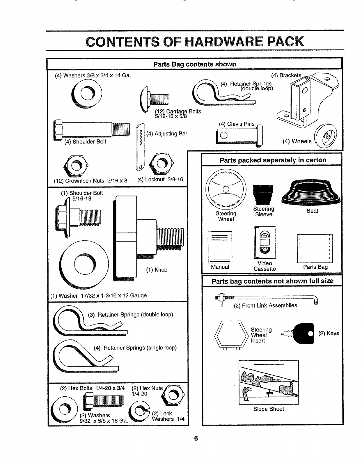
CONTENTS OF HARDWARE PACK
.................................................. iiii iillllllllllllllllllllli,iiiii
(4) Washers 3/8 x 3/4 x 14 Gao
Parts Bag contents shown
............................... i II I IIIllU II
(4) Brackets_-_
(4) Retainer.Spr!ngs _ "<
Iie loop_
(12) Carriaqe Bolts
5/16-18 x 578
IC--_- I1(4)Clevis Pins_ (4) Wheels @
(4) Adjusting Bar(4) Shoulder Bolt t_
(12) Crownlock Nuts 3/16 x 8 (4) Locknut 3/8-16
(1) Shoulder Bolt
5/16-18
(1) Knob
'1) Washer 17/32 x 1-3/16 x 12 Gauge
L i ill illll ill IIHll
(2) Hex Bolts 1/4-20 x 3/4 (2) Hex Nuts
1/4-20
(2) Washers (2) Lock
9/32 x 5/8 x 16 Ga,
................ ii ii i. ,lllllllll
1/4
Steering
Wheel
Steering Seat
Sleeve
Video ...................'
Manual Cassette Parts Bag
Parts bag contents not shown full siz e...............
(2) FrontLink Assemblies
Steering
Wheel
Insert (2) Keys
Slope Sheet
6
LY
Your new tractor has been assembled at the factorywith the exception of those parts left unassembled fo rshipping purposes..
To ensure safe and proper operation of your tractor al! parts and hardware you assemble must be tightened securely. Use
the correct tools as necessary to insure proper tightness.,
TOOLS REQUIRED FOR ASSEMBLY
A socket wrench set will make assembly easier,. Standard
wrench sizes are listed..
(2) 7/16" wrenches Tire pressure gauge
(1) 1/2" wrench Utility knife
(1) 9/16" wrench
(1) 3/4" socket with drive ratchet
When right or left hand is mentioned in this manual, it
means when you are in the operating position (seated
behind the steering wheel)°
TO REMOVE TRACTOR FROM CARTON
UNPACK CARTON
•Remove all accessible loose parts and parts cartons
from carton (See page 6),,
•Cut, from top to bottom, along lines on alt four corners
of carton, and lay panels flat.
,o Check for any additional loose parts or cartons and
remove°
BEFORE ROLLING TRACTOR OFFSKID
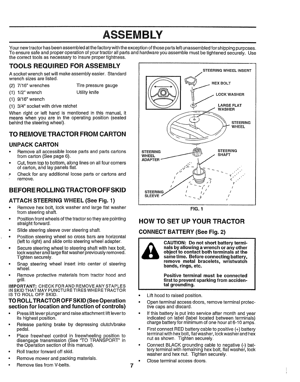
ATTACH STEERING WHEEL (See Fig. 1)
•Remove hex bolt, lock washer and large fiat washer
from steering shaft..
•Position front wheels of the tractor so they are pointing
straight forward.
°Slide steering sleeve over steering shaft,.
°Position steering wheel so cross bars are horizontal
(left to right) and slide onto steering wheel adapter.
.Secure steering wheel to steering shaft with hex bolt,
lock washer and large flat washer previously removed.,
Tighten securely.
•Snap steering wheel insert into center of steering
wheel.
o Remove protective materials from tractor hood and
grill.
IMPORTANT: CHECK FOR AND REMOVE ANY STAPLES
IN SKIDTHAT MAY PUNCTURETIRES WHERE TRACTOR
IS TO ROLL OFF SKID.
TO ROLLTRACTOR OFF SKID (See Operation
section for location and function of controls)
° Press lift lever plunger and raise attachment lift lever to
its highest positiono
° Release parking brake by depressing clutch/brake
pedal.
• Place freewheel control in freewheeling position to
disengage transmission (See 'TO TRANSPORT" in
the Operation section of this manual)..
•Roll tractor forward off skid.
° Remove mower and packing materials..
° Remove ties from V-belts,
STEERING WHEEL INSERT
STEERING _,_,_ STEERING
WHEEL _ _LLIL)_ /SHAFT
ADAPTER
I/.# I_ _ t_" / i i" "
STEERING/ I t / / /
SLEEVE /" _ _ !/- l/
FIG. 1
HOW TO SET UP YOUR TRACTOR
CONNECT BATTERY (See Fig. 2)
7
•Lift hood to raised position°
• Open terminal access doors, remove terminal protec-
tive caps and discard.
° If this battery is put into service after month and year
indicated on label (label located between terminals)
charge battery for minimum of one hour at 6-10 amps.
• First connect RED battery cable to positive (+) battery
terminal with hex bolt, flat washer, lock washer and hex
nut as shown, Tighten securely,
•Connect BLACK grounding cable to negative (-) bat-
tery terminal with remaining hex bolt, fiat washer, lock
washer and hex nut. Tighten securely.
• Close terminal access doors.
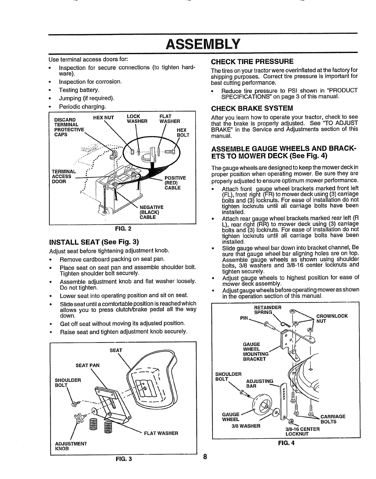
BLY
Use terminal access doors for:
- Inspection for secure connections (to tighten hard-
ware).
• Inspection for corrosion°
•Testing battery,,
• Jumping (if required)_
Periodic charging,,
DISCARD HEX NUT LOCK FLAT
WASHER WASHER
TERMINAL "_'_ \\\
PROTECTIVE /HEX
CAPS _BOLT
(RED)
CABLE
TERMINAL ;*"°
ACCESS ' .
ooo. '/ I
NEGATIVE
(BLACK)
CABLE
FIG. 2
INSTALL SEAT (See Fig. 3)
Adjust seat before tighteningadjustment knob.
, Remove cardboard packingon seat pan.
• Place seat on seat pan and assemble shoulder bolt.
Tighten shouIder bolt securely_
° Assemble adjustment knob and fiat washer loosely.
Do not tighten,
° Lower seat into operating position and sit on seat°
• Slide seat until acomfortable position is reached which
allows you to press clutch/brake pedal all the way
down,,
. Get off seat without moving its adjusted position.
• Raise seat and tighten adjustment knob securely.
SEAT
.LO LDER")-\. \\\
ADJUSTMENT
KNOB
CHECK TIRE PRESSURE
The tireson yourtractorwere overinflated at the factory for
shipping purposes. Correct tire pressure is importantfor
best cutting performance.
°Reduce tire pressure to PSI shown in "PRODUCT
SPECIFICATIONS" on page 3 of this manual
CHECK BRAKE SYSTEM
After you learn how to operate your tractor, check to see
that the brake is properly adjusted. See "TO ADJUST
BRAKE" in the Service and Adjustments section of this
rnanuai.
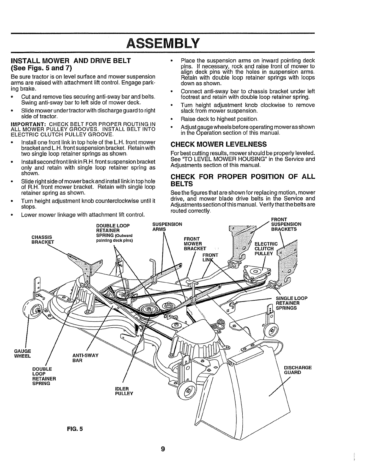
ASSEMBLE GAUGE WHEELS AND BRACK-
ETS TO MOWER DECK (See Fig. 4)
The gauge wheelsare designed to keep the mower deck in
proper position when operating mower, Be sure they are
properly adjusted to ensure optimum mower performance°
- Attach front gauge wheel brackets marked front left
(FL), front right (FR) to mower deck using (3) carriage
bolts and (3) Iocknuts. For ease of installation do not
tighten Iocknuts until all carriage bolts have been
installed.
• Attach rear gauge wheel brackets marked rear left (R
L), rear right (RR) to mower deck using (3) carriage
bolts and (3) iocknuts. For' ease of installation do net
tighten Iocknuts until all carriage bolts have been
installed.
= Slide gauge wheel bar down into bracket channel, Be
sure that gauge wheel bar aligning holes are on top.
Assemble gauge wheels as shown using shoulder'
bolts, 3/8 washers and 3/8-16 center locknuts and
tighten securely.
• Adjust gauge wheels to highest position for' ease of
mower deck assembly_
° Adjust gaugewheels before operating mower as shown
in the operation section of this manual°
RETAINDER
SPRING
PIN_ \I_CROWNLOCK
WHEEL/'_ I
MOUNTING _
BRACKET _
SHOULDER I!(_{[
BOLT,= ADJUSTING "_ f!__,'_ /
GAUGE I"- _/_J'_! _J. _--,,,,,_ CARRIAGE
WHEEL _ _ __ BOLTS
3/8 WASHER -
3/8_16 CENTER
LOCKNUT
FIG. 4
FIG. 3 8
i
MBLY
,, ,,,,,,,,,,,,,,,,,,,,,,,,,,,,, ,,,,,, ,,,,,,,,,,,,,,,,',,,,,,,,,,,,,,,,lll./lllJ.lll II,..ll.l.lll
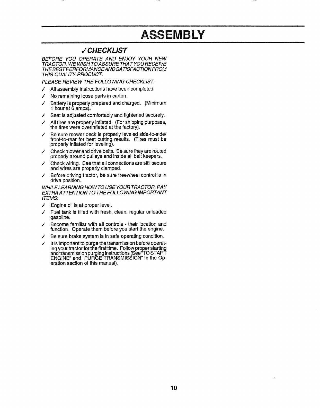
INSTALL MOWER AND DRIVE BELT
(See Figs. 5 and 7)
Be sure tractor is on leve! surface and mower suspension
arms are raised with attachment lift control Engage park_
ing brake°
° Cut and remove ties securing anti-sway bar and belts.,
Swing anti-sway bar to left side of mower deck. o
= Slide mower under tractorwith discharge guard to right
side of tractor. =
e
IMPORTANT: CHECK BELT FOR PROPER ROUTING IN
ALL MOWER PULLEY GROOVES. INSTALL BELT INTO
ELECTRIC CLUTCH PULLEY GROOVE,,
° Instal! one front link intop hole of the LH. front mower
bracket and L,.Hofront suspension bracket, Retain with
two single loop retainer springs as shown.
= Install second front link inRoHofront suspension bracket
only and retain with single loop retainer spring as
shown.
° Slide right side of mower back and install link in top hole
of RoH. front mower bracket., Retain with single loop
retainer spring as shown°
° Turn height adjustment knob counterclockwise until it
stops.,
= Lower mower linkage with attachment iift control.
DOUBLE LOOP
RETAINER
CHASSIS SPRING (Outward
BRACKET pointing deckpins)
Place the suspension arms on inward pointing deck
pins. If necessary, rock and raise front of mower to
align deck pins with the ho!es in suspension arms.,
Retain with double loop retainer springs with loops
down as shown.
Connect anti-sway bar to chassis bracket under left
footrest and retain with double loop retainer spring.,
Turn height adjustment knob clockwise to remove
slack from mower suspension,,
Raise deck to highest position.,
Adjust gauge wheels before operating mower as shown
inthe Operation section of this manual.
CHECK MOWER LEVELNESS
For best cutting results, mower should be propedy leveled.
See "TO LEVEL MOWER HOUSING" in the Service and
Adjustments section of this manual
CHECK FOR PROPER POSITION OF ALL
BELTS
See the figures that are shown for replacing motion, mower
drive, and mower blade drive belts in the Service and
Adjustments section of this manual., Verify that the belts are
routed correctly,
SUSPENSION
ARMS
FRONT
SUSPENSION
BRACKETS
FRONT
MOWER
BRACKET _'
FRONT
ELECTRIC
CLUTCH
PULLEY
SINGLE LOOP
RETAINER
SPRINGS
GAUGE
WHEEL /
DOUBLE
LOOP
RETAINER
SPRING
ANTI-SWAY
BAR
/
IDLER
PULLEY
DISCHARGE
GUARD
FIG. 5
9
BLY
,/CHECKLIST
BEFORE YOU OPERATE AND ENJOY YOUR NEW
TRACTOR, WE WISH TO ASSURE THAT YOU RECEIVE
THEBESTPERFORMANCEAND SATISFACTION FROM
THIS QUALITY PRODUCT°
PLEASE REVIEW THE FOLLOWING CHECKLIST:
,/ All assembly instructions have been completed°
V' No remaining loose parts in carton.
¢" Battery is properly prepared and charged. (Minimum
! hour at 6 amps)o
,/ Seat is adjusted comfortably and tightened securely°
¢ All tires are properly inflated. (For shipping purposes,
the tires were ovennflated at the factory).
¢ Be sure mower' deck is properly leveled side-to-side/
front-to-rear for best cutting results, (Tires must be
properly inflated for' leveling).
¢' Check mower and drive belts. Be sure they are routed
properly around pulleys and inside all belt keepers°
¢' Check wiring. See that all connections are still secure
and wires are properly clamped.
¢" Before driving tractor, be sure freewheel control is in
drive position,
WHILE LEARNING HOW TO USE YOUR TRACTOR, PAY
EXTRA A TTENTION TO THE FOLLOWING IMPORTANT
ITEMS:
¢" Engine oil is at proper level.
,/ Fuel tank is filled with fresh, clean, regular unleaded
gasoline,
¢ Become familiar with all controls - their location and
function. Operate them before you start the engine.
v" Be sure brake system is in safe operating condition..
¢" It is important to purge the transmission before operat-
ing your tractor for the first time. Follow proper starting
and transmission purging instructions (See 'TO START
ENGINE" and "PURGE TRANSMISSION" in the Op-
eration section of this manual).
10
OPERA
/,U,ll I,nn
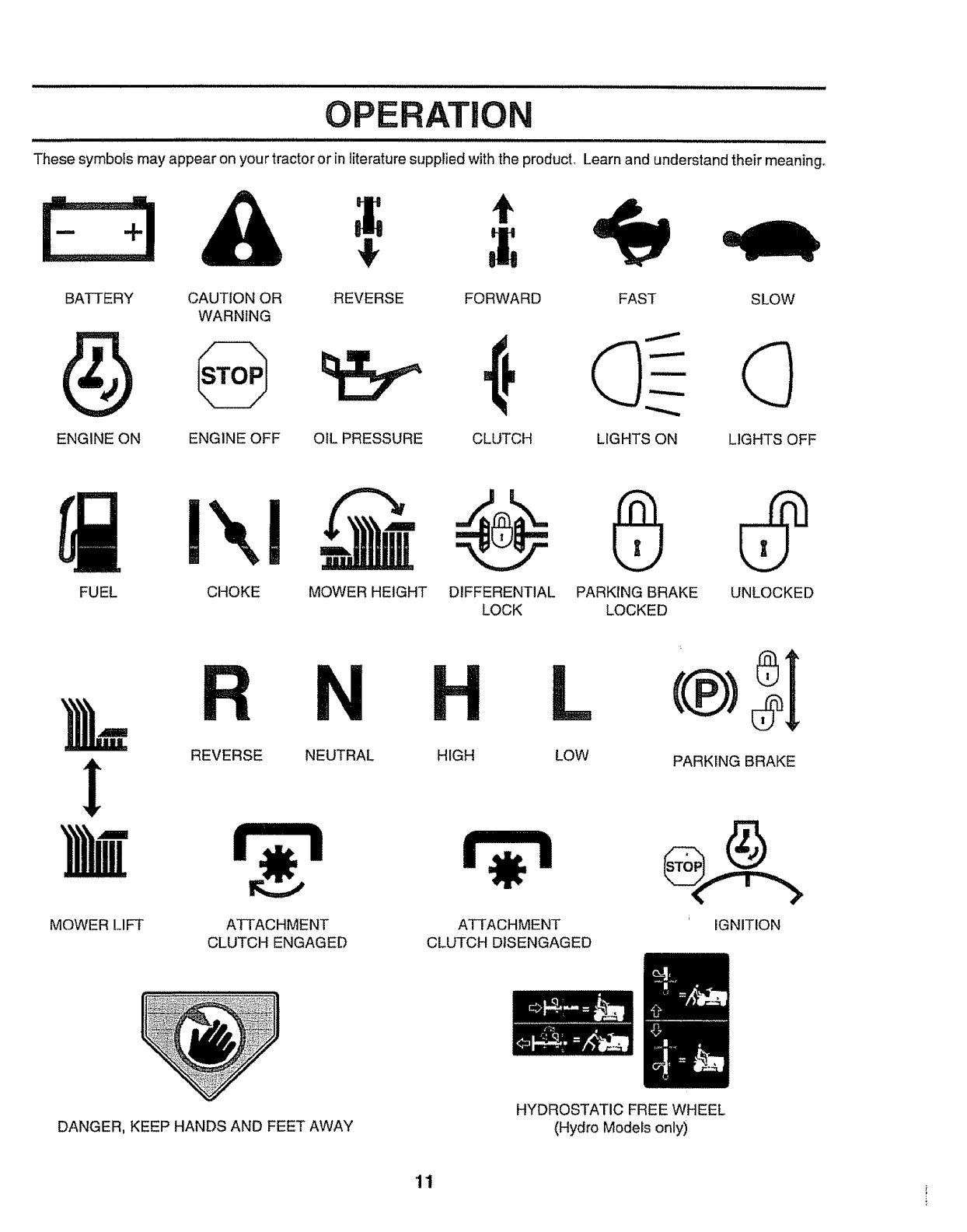
These symbols may appear on your tractor or in literature supplied with the producL Learn and understand their meaning_
4, t
BATTERY CAUTION OR REVERSE
WARNING
ENGINE ON ENGINE OFF OIL PRESSURE
FORWARD FAST SLOW
CLUTCH LIGHTS ON LIGHTS OFF
FUEL CHOKE MOWER HEIGHT DIFFERENTIAL
LOCK PARKING BRAKE UNLOCKED
LOCKED
!
MOWER LIFT
RN
REVERSE NEUTRAL HIGH
ATTACHMENT
CLUTCH ENGAGED
L
LOW
ATTACHMENT
CLUTCH DISENGAGED
PARKING BRAKE
IGNITION
DANGER, KEEP HANDS AND FEET AWAY
HYDROSTATIC FREE WHEEL
(Hydro Models only)
'11
.............. iilll illl ii ii ill iii ill
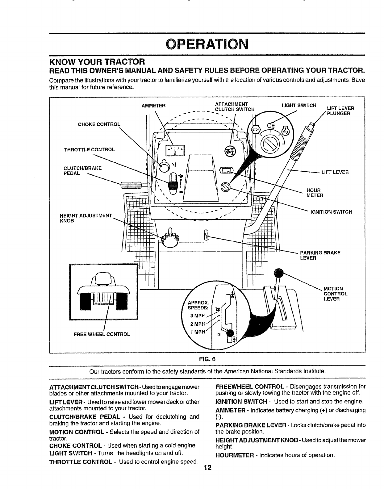
OPERATI
............... ,,, ,,,,, ,,,,,, ,,,, i.
KNOW YOUR TRACTOR
READ THIS OWNER'S MANUAL AND SAFETY RULES BEFORE OPERATING YOUR TRACTOR.
Compare the illustrations with your tractor to familiarize yourself with the location of various controls and adjustments_ Save
this manual for future reference.
CHOKECONTROL
THROTTLECONTROL
CLUTCH_RAKE
PEDAL
HEIGHT ADJUSTMENT
KNOB
AMMETER ATTACHMENT LIGHT SWITCH
CLUTCH SWITCH LIFT LEVER
3LUNGER
LIFT LEVER
HOUR
METER
IGNITION SWITCH
PARKING BRAKE
LEVER
FREE WHEEL CONTROL
SPEEDS:
3
2
MOTION
CONTROL
LEVER
FIG. 6
Our tractors conform to the safety standards of the American National Standards Institute.
ATTACHMENTCLUTCH SWITCH- Used to engage mower'
blades or other attachments mounted to your tractor.
LIFT LEVER- Used to raiseand lower mower deck orother
attachments mounted to your tractor°
CLUTCH/BRAKE PEDAL - Used for declutching and
braking the tractor and starting the engine,
MOTION CONTROL - Selects the speed and direction of
tractor.
CHOKE CONTROL - Used when starting a cold engine.
LIGHT SWITCH * Turns the headlights on and off
THROTTLE CONTROL - Used to control engine speed, 12
FREEWHEEL CONTROL - Disengages transmission for
pushing or slowly towing the tractor with the engine off°
IGNITION SWITCH - Used to start and stop the engine_
AMMETER - Indicates battery charging (+) or discharging
(-).
PARKING BRAKE LEVER - Locks dutch/brake pedal into
the brake position.
HEIGHT ADJUSTMENT KNOB- Used to adjust the mower
height,
HOURMETER ° Indicates hours of operation_
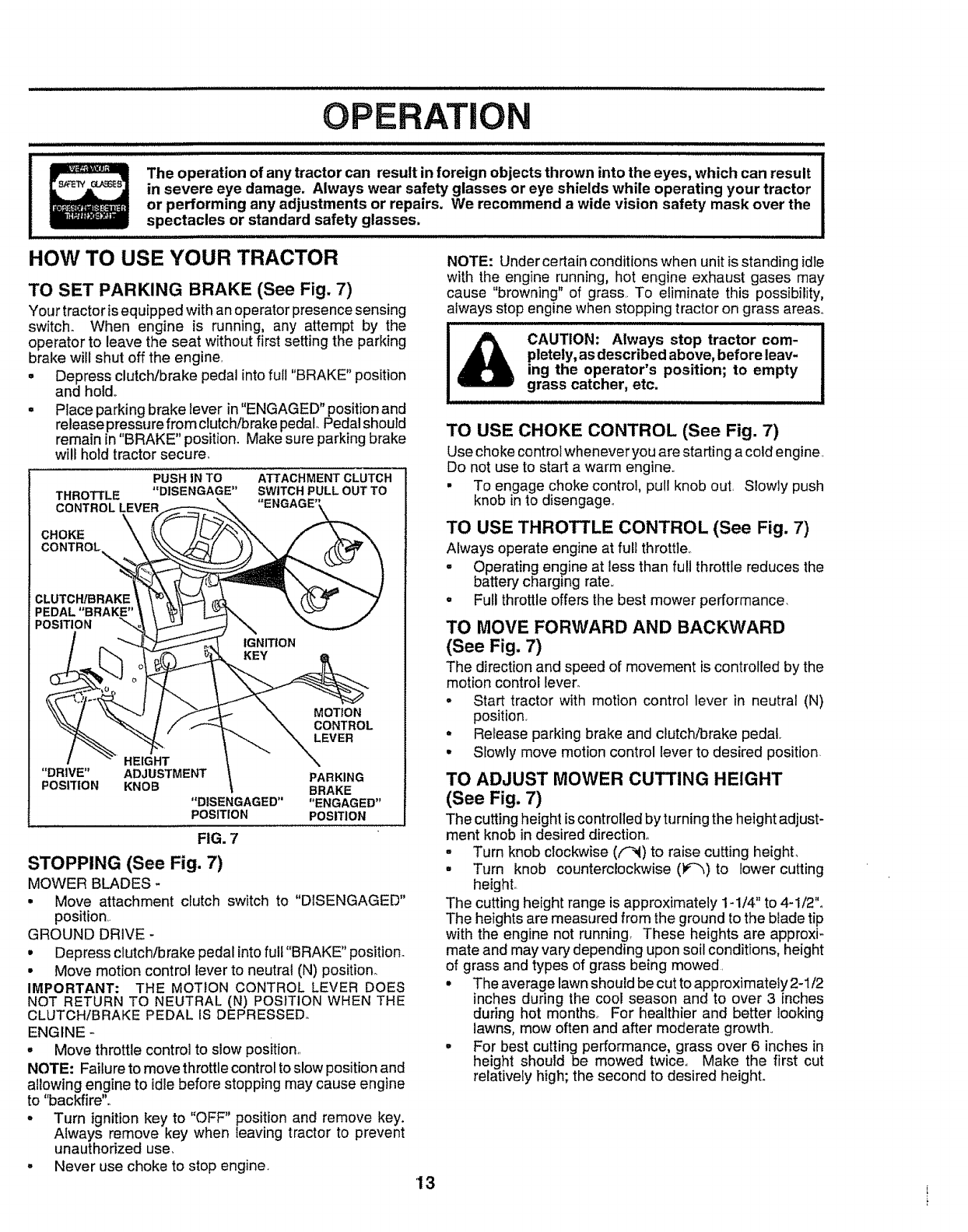
OPERATION
i i illll i] ill illlllllll,i
The operation of any tractor can result in foreign objects thrown into the eyes, which can result
in severe eye damage. Always wear safety glasses or eye shields while operating your tractor
or performing any adjustments or repairs. We recommend a wide vision safety mask over the
spectacles or standard safety glasses.
HOW TO USE YOUR TRACTOR
TO SET PARKING BRAKE (See Fig. 7)
Your tractor isequipped with an operator presence sensing
switch. When engine is running, any attempt by the
operator to leave the seat without first setting the parking
brake will shut off the engine,
° Depress clutch/brake pedal intofull "BRAKE" position
and hold,,
.Place parking brake lever in "ENGAGED" position and
release pressure from clutch/brake pedal. Pedal should
remain in "BRAKE" position. Make sure parking brake
will hold tractor secure.
PUSH IN TO ATTACHMENT CLUTCH
THROTTLE "DISENGAGE" SWITCH PULL OUT TO
CONTROL LEVER
CHOKE
CONTROL_
CLUTCH/BRAKE
IPEDAL"BRAKE"
POSITION
IGNITION
HEIGHT
"DRIVE" ADJUSTMENT
POSITION KNOB
"DISENGAGED"
POSITION
MOTION
CONTROL
LEVER
\.
PARKING
BRAKE
"ENGAGED"
POSITION
FIG. 7
STOPPING (See Fig. 7)
MOWER BLADES -
•Move attachment clutch switch to "DISENGAGED"
position
GROUND DRIVE-
•Depress clutch/brake pedal intofull "BRAKE" position.
• Move motion control lever to neutral (N) position.
IMPORTANT: THE MOTION CONTROL LEVER DOES
NOT RETURN TO NEUTRAL (N) POSITION WHEN THE
CLUTCH!BRAKE PEDAL IS DEPRESSED.
ENGINE -
o Move throttle control to slow position,,
NOTE: Failure to move throttle control to slow position and
allowing engine to idle before stopping may cause engine
to "backfire".
-Turn ignition key to "OFF" position and remove key.
Always remove key when leaving tractor to prevent
unauthorized use,
o Never use choke to stop engine,
NOTE: Under certain conditions when unit is standing idle
with the engine running, hot engine exhaust gases may
cause "browning" of grass,. To eliminate this possibility,
always stop engine when stopping tractor on grass areas°
i, ,i
CAUTION: Always stop tractor com-
pletely, as described above, before leav-
ing the operator's position; to empty
grass catcher, etc.
TO USE CHOKE CONTROL (See Fig. 7)
Use choke control whenever you are starting a cold engine,
Do not use to start a warm engine.,
• To engage choke control, pull knob out, Slowly push
knob in to disengage,,
TO USE THROTTLE CONTROL (See Fig. 7)
Always operate engine at full throttle,.
.Operating engine at less than full throttle reduces the
battery charging rate,,
•Full throttle offers the best mower performance,
TO MOVE FORWARD AND BACKWARD
(See Fig. 7)
The direction and speed of movement is controlled by the
motion control lever_
• Start tractor with motion control lever in neutral (N)
position.
° Release parking brake and clutch/brake pedal.
•Slowly move motion control lever to desired position.
TO ADJUST MOWER CUTTING HEIGHT
(See Fig. 7)
The cutting height is controlled by turning the height adjust-
ment knob in desired direction°
- Turn knob clockwise ((-_) to raise cutting height,
• Turn knob counterclockwise ()r--_) to lower cutting
height_
The cutting height range is approximately 1-1/4" to 4-1/2"o
The heights are measured from the ground to the blade tip
with the engine not running, These heights are approxi-
mate and may vary depending upon soil conditions, height
of grass and types of grass being mowed.
• The average lawn should becut to approximately 2-1/2
inches during the cool season and to over 3 inches
during hot months° For healthier and better looking
lawns, mow often and after moderate growth,.
= For best cutting performance, grass over 6 inches in
height should be mowed twice., Make the first cut
relatively high; the second to desired height.
'13
N
UlL II Illl
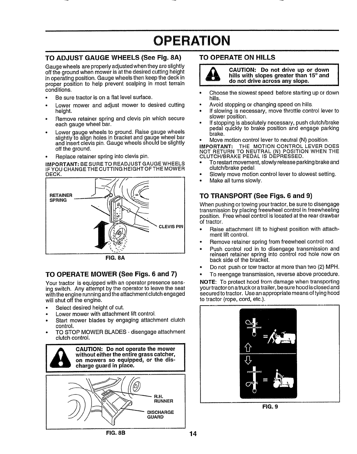
TO ADJUST GAUGE WHEELS (See Fig, 8A)
Gauge wheels are properly adjusted when theyare stightly !
off the ground when mower is at the desired cutting height I
inoperating position. Gauge wheels then keep the deck in
proper position to help prevent scalping in most terrain
conditions°
•Be sure tractor is on a flat level surface..
• Lower mower and adjust mower to desired cutting
height.
° Remove retainer spring and clevis pin which secure
each gauge wheel bar°
• Lower gauge wheels to ground. Raise gauge wheels
slightly to align holes in bracket and gauge wheel bar
and insert clevis pin. Gauge wheels should be slightly
off the ground..
°Replace retainer spring into clevis pin.
IMPORTANT: BE SURE TO READJUST GAUGE WHEELS
IF YOU CHANGE TH ECUTTING HEIGHT OFTHE MOWER
DECK.
ii i i i i lllll illlllllljlliJll
TO OPERATE ON HILLS
RETAINER
SPRING
CLEVIS PIN
TO OPERATE MOWER (See Figs. 6 and 7)
Your tractor is equipped with an operator presence sens-
ing switch.. Any attempt by the operator to leave the seat
with the engine runningand the attachment clutch engaged
wilt shut off the engine.
• Select desired height of cut.
° Lower' mower with attachment lift control
• Start mower blades by engaging attachment clutch
control.
° TO STOP MOWER BLADES- disengage attachment
clutch control.
............... iiiil, l,i ill
CAUTION: Do not operate the mower
without either the entire grass catcher,
on mowers so equipped, or the dis-
charge guard in place.
..................... i ± ii JlL"
CAUTION: Do not drive up or down I
!
hills with slopes greater than 15° and I
do not drive across any slope.
• Choose the slowest speed before starting up or down
hills.
,Avoid stopping or changing speed on hills.
° If slowing is necessary, move throttle control lever to
slower position.
,If stopping is absolutely necessary, push clutch/brake
pedal quickly to brake position and engage parking
brake.
,Move motion contro_ lever to neutral (N) position.
IMPORTANT: THE MOTION CONTROL LEVER DOES
NOT RETURN TO NEUTRAL (N) POSITION WHEN THE
CLUTCH/BRAKE PEDAL IS DEPRESSED.
° To restart movement, slowly release parking brake and
clutch/brake pedal.
= Slowfy move motion control lever to slowest setting.
• Make all turns slowly.
TO TRANSPORT (See Figs. 6 and 9)
When pushing or towingyour tractor, be sure to disengage
transmissionby placing freewheel control in freewheeling
position. Free wheel controlis located at the rear drawbar
of tracton
•Raise attachment lift to highest position with attach-
ment lift control.
° Remove retainer spring from freewheel control rod.
° Push control rod in to disengage transmission and
reinsert retainer spring into control rod hole now on
back side of the bracket.
o Do not push or'tow tractor at more than two (2) MPH.
• To reengagetransmission, reverse above procedure.
NOTE: To protect hood from damage when transporting
your tractor on atruckor atrailer, be sure hood is closed and
secured to tracton Use an appropriate means of tying hood
to tractor (rope, cord, etc.)o
R,R.
RUNNER
DISCHARGE
GUARD
FIG. 9
FIG. 8B 14
O ERATION
BEFORE STARTING THE ENGINE
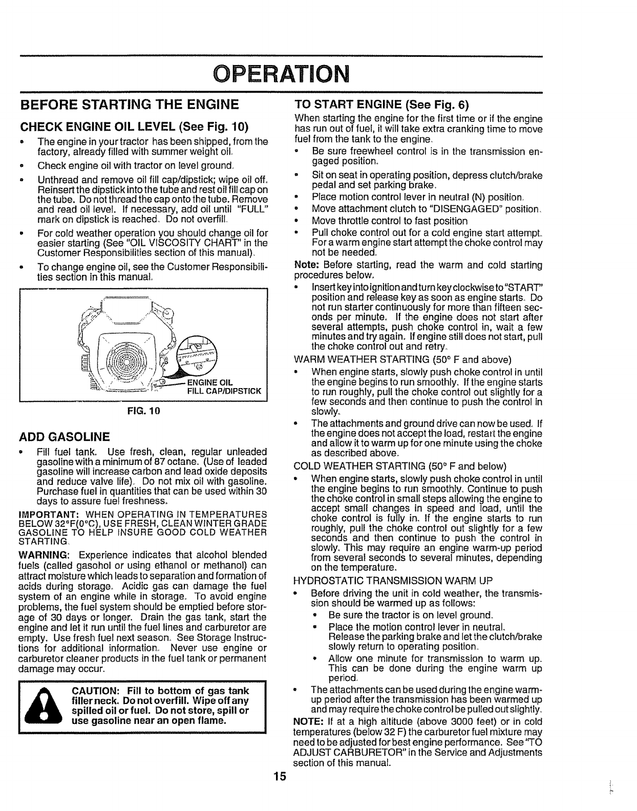
CHECK ENGINE OIL LEVEL (See Fig. 10)
= The engine in yourtractor has been shipped, from the
factory, already filled with summer weight oil
.Check engine oil with tractor on level ground,
°Unthread and remove oil fill cap/dipstick; wipe oil off,.
Reinsert the dipstick into the tube and rest oil fill cap on
the tube. Do not thread the cap onto the tube. Remove
and read oil level. If necessary, add oil until "FULL"
mark on dipstick is reached. Do not overfill..
•For cold weather operation you should change oil for
easier starting (See "OIL VISCOSITY CHART" inthe
Customer Responsibilities section of this manual).
= To change engine oil, see the Customer Responsibi{i-
ties section in this manual,,
.....%'=-_=--=-_=_" _'_" FILL CAP/DIPSTICK
FIG. 10
ADD GASOLINE
• Fill fuel tank. Use fresh, clean, regular unleaded
gasoline with a minimum of 87 octane,, (Use of leaded
gasoline will increase carbon and lead oxide deposits
and reduce valve life).. Do not mix oi! with gasoline.
Purchase fuel in quantities that can be used within 30
days to assure fuel freshness.
IMPORTANT: WHEN OPERATING IN TEMPERATURES
BELOW 32°F(0°C), USE FRESH, CLEAN WINTER GRADE
GASOLINE TO HELP INSURE GOOD COLD WEATHER
STARTING..
WARNING: Experience indicates that alcohol blended
fuels (called gasohol or using ethanol or methanol) can
attract moisture which leads to separation and formation of
acids during storage° Acidic gas can damage the fuel
system of an engine while in storage° To avoid engine
problems, the fuel system should be emptied before stor-
age of 30 days or longer. Drain the gas tank, start the
engine and let it run until the fuel lines and carburetor are
empty. Use fresh fuel next season,. See Storage Instruc-
tions for additional information,. Never use engine or
carburetor cleaner products in the fuel tank or permanent
damage may occur.
CAUTION: Fill to bottom of gas tank
fillerneck° Do not overfill. Wipe offany
spilled oil or fuel. Do not store, spill or
use gasoline near an open flame.
15
TO START ENGINE (See Fig. 6)
When starting the engine for the first time or if the engine
has run out of fuel, it will take extra cranking time to move
fuel from the tank to the engine_
•Be sure freewheel control is in the transmission en-
gaged position°
° Sit on seat inoperating position,depress clutch/brake
pedal and set parking brake.
• Place motion control lever in neutral (N) position.
•Move attachment clutch to "DISENGAGED" position.
°Move throttle control to fast position
• Pull choke control out for a cold engine start attempt,.
For a warm enginestart attempt the choke control may
not be needed_
Note: Before starting, read the warm and cold starting
procedures below.
• Insert keyinto ignition and turn key clockwise to"START"
position and release key as soon as engine starts_ Do
not run starter continuously for more than fifteen sec-
onds per minute,. If the engine does not start after
several attempts, push choke control in, wait a few
minutes and try again, if engine still does not start, pull
the choke control out and retry°
WARM WEATHER STARTING (50° F and above)
•When engine starts, slowly push choke control in until
the engine begins to run smoothly, If the engine starts
to run roughly, pullthe choke control out slightly for a
few seconds and then continue to push the control in
slowly..
= The attachments and ground drive can now be used., If
the engine does not accept the load, restart the engine
and atlow itto warm up for one minute using the choke
as described above.
COLD WEATHER STARTING (50° F and below)
°When engine starts, slowly push choke control in until
the engine begins to run smoothly,. Continue to push
the choke control insmall steps allowing the engine to
accept small changes in speed and load, until the
choke control is fully in. if the engine starts to run
roughly, pull the choke control out slightly for a few
seconds and then continue to push the control in
slowly. This may require an engine warm-up period
from several seconds to several minutes, depending
on the temperature°
HYDROSTATIC TRANSMISSION WARM UP
° Before ddving the unit in cold weather, the transmis-
sion should be warmed lip as follows:
°Be sure the tractor is on level ground.
. Place the motion control lever in neutral
Release the parking brake and let the clutch/brake
slowly return to operating positlono
°Allow one minute for transmission to warm up,.
This can be done during the engine warm up
period_
• The attachments can be used during the engine warm-
up period after the transmission has been warmed up
and may require the choke control be pulled out sfightiy.
NOTE: If at a high altitude (above 3000 feet) or in cold
temperatures (below 32 F) the carburetor fuel mixture may
need to be adjusted for best engine performance, See 'qO
ADJUST CARBURETOR" in the Service and Adjustments
section of this manual.
i i illllllul ii ii i1,,, OPERATION
PURGE TRANSMISSION
ill i_u,i .............................................
CAUTION: Never engage or disengage
freewheel lever while the engine is run-
ning.
........................... iiiii
To ensure proper operation and performance, it is recom-
mended that the transmission be purged before operating
tractor-for the first time. This procedure will remove any
trapped air inside the transmission which may have devel-
oped during shipping of your tractor.
IMPORTANT: SHOULD YOUR TRANSMISSION REQUIRE
REMOVAL FOR SERVICE OR REPLACEMENT, IT
SHOULD BE PURGED AFTER REtNSTALLATION
BEFORE OPERATING THE TRACTOR
• Place tractor safely on level surface with engine off and
parking brake set.
oDisengage transmission by placing freewheel control
in freewheeling position (See "TO TRANSPORT" in
this section of manual)_
•Sittingin the tractor seat, start engine_ After'the engine
is running, move throttle control to slow position. With
motion control lever in neutral (N) position, slowly
disengage clutch/brake pedal.
•Move motion control lever to full forward position and
hold for five (5) seconds Move lever to full reverse
position and hold for five (5) seconds_ Repeat this
procedure three (3) times.
NOTE: During this procedure there will be no movement of
drive wheets. The air is being removed from hydraulic drive
system...
, Move motion controlleverto neutral (N) position. Shut-
off engine and set parking brake.
o Engage transmission by placing freewheel control in
driving position (See "TO TRANSPORT" inthis section
of manual).
° Sitting inthe tractor seat, start engine, Afterthe engine
is running, move throttle control to half (1/2) speed.
With motion control lever in neutral (N) position, slowly
disengage clutch/brake pedal.
° Slowly move motion control lever forward, after the
tractor moves approximately five (5) feet, slowly move
motion control lever to reverse position.. After the
tractor moves approximately five (5) feet return the
motion control lever to the neutral (N) position, Repeat
this procedure with the motion control lever three (3)
times°
°Your tractor is now purged and now ready for normal
operation,
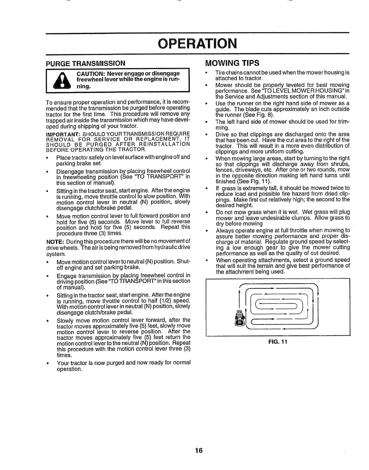
MOWING TIPS
°Tire chainscannot be used when the mower housing is
attached to tractor_
°Mower should be propedy leveled for best mowing
performance.. See "TO LEVEL MOWER HOUSING" in
the Set€ice and Adjustments section of this manual.
oUse the runner on the right hand side of mower' as a
guide. The blade cuts approximately an inch outside
the runner (See Fig_8)_
° The left hand side of mower should be used for trim-
ming_
° Drive so that clippings are discharged onto the area
that has been cuL Have the cut area to the rightof the
tractor_ This will result in a more even distribution of
clippings and more uniform cutting.
° When mowing large areas, start by turning to the right
so that clippings will discharge away from shrubs,
fences, driveways, etc_ After one or two rounds, mow
in the opposite direction making left hand turns until
finished (See Fig° 11)_
°If grass is extremely tall, it should be mowed twice to
reduce load and possible fire hazard from dried clip-
pings. Make first cut relatively high; the second to the
desired height.
° Do not mow grass when it is wet. Wet grass wilt plug
mower and leave undesirable clurnps. Allow grass to
dry before mowing.
°Always operate engine at futl throttle when mowing to
assure better mowing performance and proper dis-
charge of material. Regulate ground speed by select-
ing a low enough gear to give the mower cutting
performance as welt as the quality of cut desired.
° When operating attachments, select a ground speed
that wilt suit the terrain and give best performance of
the attachment being used.
FIG. 11
16

i i iiiilu ,11
CUSTOMER
u i iii
ESPONSmBILITIES
MAINTENANCE SCHEDULE ____o__
AS YOU COMPLETE /_.O_',_" ........
REGULAR SERVICE ___",_" SERVICE DATES
Check Brake Operation _
Check T_re Pressure if
Tcheck for Lo0se"Fasie'ners V#
R Sharper,JReplaee"Mower Blades ............ 6#44 "
AEubricati0n Chart
C .......... ............................... =
Check Battery Leve]lRecharge
...................................... u
Clean Battery and Terminals
Cl_eck Transaxle Cooling
Adjust BIade Belt(s) Tension
Aa]ustMOiio."Dr_eaeit(s)Tens_O".....
Check Engine Oil Level _
Change Engine Oil _,2,3
Clean Air Filter
E...........................
Clean Air Screen
G Inspect MufflerlSpark Arrestor
I Replace Oil FiIter (If equipped)
N cIe_nE"gi.ocoo,_;gFins............
F.
I I
Replace Spark Plug
Replace Air Filter Paper Cartridge
Replace Fuel Filter
1-Change morn ellen when operating undera heavy loadorInhigh ambEenttemperatures
2- Service more ellen when operating In dirty or dusty conditions.
3 - If equipped with oil tilter, change oil eve_ 50 hours,
4-Replace blades more often when mewing in sandy soil
v"
v'
v%
v"o
v'
v'2 v'
v'2
.........! v' ......
!v'2
5-if equippedwithadjusfablesystem,
6- Not requiredtt equippedwithmaintenance4reebatteq/
7- Tighten frontaxle pivot boltto 35 fl,-lbs maximum
Do not overtighten
GENERAL RECOMMENDATIONS
The warranty on this tractor does not cover items that have
been subjected to operator abuse or negligence.. To
receive full value from the warranty, operator must maintain
tractor as instructed in this manual.
Some adjustments will need to be made periodically to
properly maintain your tractor.
All adjustments inthe Service and Adjustments section of
this manual should be checked at least once each season..
•Once a year you should replace the spark plug, clean
or replace air filter, and check blades and belts for
wear. A new spark plug and clean air filter assure
proper air-fuel mixture and help your engine run better
and last Iongero
®
LUBRICATION CHART
_TIE ROD BALL JOINTS
SPINDLE ZERK ®
® WHEEL ®
BEARING ZERK BEARING ZERK
®SECTOR GEAR ENGINE (_
TEETH
BEFORE EACH USE
•Check engine oil bevel,
• Check brake operation,,
• Checktire pressure.
•Check for loose fasteners.
IMPORTANT: DO NOT OIL OR GREASE THE PIVOT POINTS
WHICH HAVE SPECIAL NYLON BEARINGS, VISCOUS LUBRI-
CANTS WILL ATTRACT DUST AND DIRT THAT WILL SHORTEN
THE LIFE OF THE SELF-LUBRICATING BEARINGS. IF YOU
FEEL THEY MUST BE LUBRICATED, USE ONLY A DRY, POW-
DERED GRAPHITE TYPE LUBRICANT SPARINGLY,,
(D SPRAY SILICONE LUBRICANT (MOVE BOOTS TO LUBRICATE)
®GENERAL PURPOSE GREASE
(_) REFER TO CUSTOMER RESPONSIBILITIES "ENGINE" SECTION
17
CU
i i illlllllll Jl
TRACTOR
Always observe safety rules when performing any mainte-
nanoe_
BRAKE OPERATION
tf tractor requires more than six (6) feet stopping distance
at high speed in highest gear, then brake must be adjusted.
(See 'TO ADJUST BRAKE" in the Service and Adjust-
ments section of this manual).
TIRES
oMaintain proper air pressure inalf tires (See "PROD-
UCT SPECIFICATIONS" on page 3 of this manual).
• Keep tires free of gasoline, oil, or insectcontrol chemi-
cals which can harm rubber_
oAvoid stumps, stones, deep ruts, sharp objects and
other hazards that may cause tire damage,.
NOTE; To seal tire punctures and prevent fiat tires due to
slow leaks, tire sealant may be purchased from your local
parts dealer., Tire sealant also prevents tire dry rot and
corrosion_
BLADE CARE
For best results mower blades must be kept sharp° Re-
place bent or damaged blades.
BLADE REMOVAL (See Fig. 12)
• Raise mower to highest position to allow access to
blades_
° Remove hex bolt, lock washer and flat washer'securing
blade..
° Install new or resharpened blade withtrailing edge up
towards deck as shown.
•Reassemble hex bolt, lock washer and flat washer' in
exact order as shown.
•Tighten bolt securely (30-35 Ft. Lbsotorque).
IMPORTANT: BLADE BOLT tS GRADE 8 HEATTREATEDo
NOTE: We do not recommend sharpening blade- but if you
do, be sure the blade is balanced_
_, MANDREL
BLADE [_,_ .ASSEMBLY
FLAT WASHER._.,,_;;_ _L /
LO CKWASHER ,,_ _'__._._../
FlEX BOLT (GRADE B)* _,,,_ ""_
*A GRADE 8 BEAT TREATED BOLT CAN BE
IDENTIFIED BY SIX LINES ON THE BOLt' HEAD.
FIG. 12
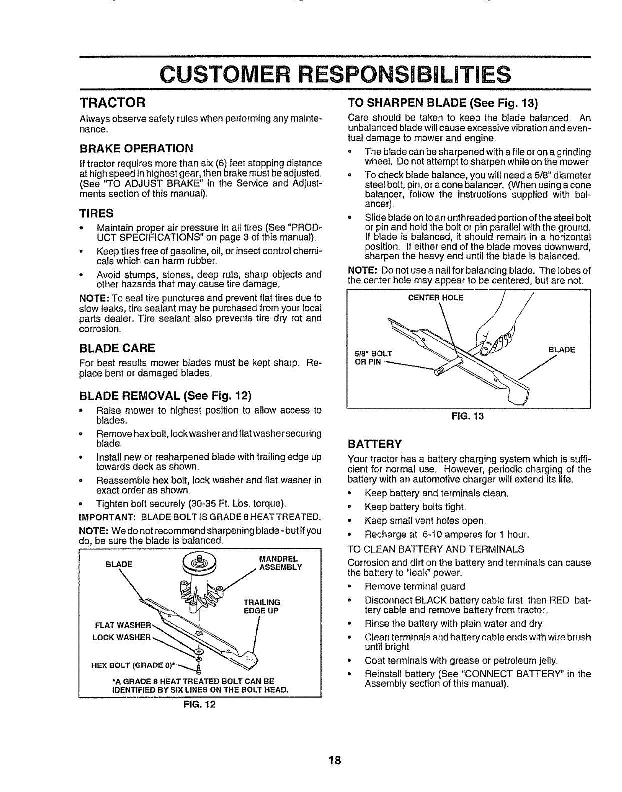
TO SHARPEN BLADE (See Fig. 13)
Care should be taken to keep the blade balanced. An
unbalanced blade will cause excessive vibration and even-
tual damage to mower and engine.
• The blade can be sharpened with a file or on a grinding
wheel. Do not attempt to sharpen while on the mower°
° To check blade balance, you will need a 5/8" diameter
steel bolt, pin, or a cone balancer_ (When using a cone
balancer, fellow the instructions supplied with bal-
ancer).
° Slide blade on to an unthreaded portion of the steel bolt
or pin and hold the bolt or pin parallel with the ground.
If blade is balanced, it should remain in a horizonta!
position° If either end of the blade moves downward,
sharpen the heavy end until the blade is balanced.
NOTE: Do not use a nail for balancing blade. The lobes of
the center' hole may appear to be centered, but are noL
5f8" BOLT
OR PIN
CENTER HOLE
BLADE
FIG. 13
BATTERY
Your tractor has abattery charging system which is suffi-
cient for normal use° However, periodic charging of the
battery with an automotive charger will extend its life,,
°Keep battery andterminaIs clean,
•Keep battery bolts tight.
•Keep small vent holes open_
•Recharge at 6-10 amperes for 1 hour:
TO CLEAN BATTERY AND TERMINALS
Corrosion and dirt on the battery and terminals can cause
the battery to "leak" power..
° Remove terminal guard.
•Disconnect BLACK battery' cable first then RED bat-
tery cable and remove battery from tractor_
°Rinse the battery with plain water and dry
• Clear] terminals and battery cable ends with wire brush
until bright_
• Coat terminals with grease or petroleum jelly.
° Reinstall battery (See "CONNECT BATTERY" in the
Assembly section of this manual)_
18
CUSTOMER
TRANSAXLE COOLING
RESPONSIBILHTIES
The fan and cooling fins of transmissionshould be kept
clean to assure proper cooling,
Do not attempt to clean fan or transmission while engine is
running or while the transmission is hot, To prevent
possible damage to seals, no not use high pressure water
or steam to dean transaxle,
• Inspect co.oling fan to be sure fan blades are intactand
clean.,
• Inspect cooling fins for dirt, grass clippings and other
materials., To prevent damage to seals, do notuse
compressed air or high pressure sprayer
TRANSAXLE PUMP FLUID
The transaxle was sealed at the factory and fluid mainte-
nance is not required for the life of the transaxle. Should
the transaxle ever leak or require servicing, contact your
nearest authorized service center/department,
V-BELTS
Check V-belts for deterioration and wear after 100 hours of
operation and replace if necessary',. The belts are not
adjustable, Replace belts if they begin to slip from wear
ENGINE
LUBRICATION
Only use high quality detergent oil rated with AP! service
classification SF, SG or SH,_Select the oil's SAE viscosity
grade according to your expected operating temperature
.... s,kEVlSCOS GRADES
°F "2£1................°t..........3o" 32'_6; 6o_ a00 !£0t
°C .30o .......... -20_ -10_ o" 10' 20_ 30° 40_
TEMPERATURE RANGE ANTICIPATED BEFORE NEXT O_L CHANGE
FIG. 14
Change the oil after every 50 hours of operation or at least
once ayear if the tractor is not used for 50 hours in one year.
Check the crankcase oil level before starting the engine
and after each eight (8) hours of operation. Tighten oil fill
cap/dipstick securely each time you check the oil level..
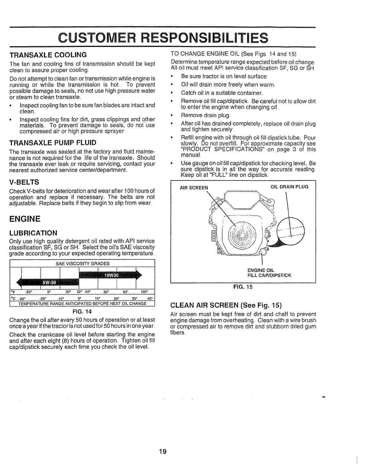
TO CHANGE ENGINE OIL (See Figs 14 and 15)
Determine temperature range expected before oil change.
All oif must meet API service classification SF, SG or SH
• Be sure tractor is on level surface.
• Oil will drain more freely when warm,,
•Catch oil in a suitable container,,
, Remove oil fill cap/dipstick Be careful not to allow dirt
to enter the engine when changing oil,
° Remove drain plug,
°After oit has drained completely, replace oi! drain plug
and tighten securely,
• RefitI engine with oil through oif fill dipstick tube. Pour
slowIy. Do not overfiIL For approximate capacity see
"PRODUCT SPECIFICATIONS" on page 3 of this
manual
.Use gauge on oil fill cap/dipstick for checking level. Be
sure dipstick is in all the way for accurate reading
Keep oil at "FULL" line on dipstick,
AIR SCREEN \÷. OIL DRAIN PLUG
ENGINE OIL
FtLL CAPtDIPSTfCK
FIG. 15
CLEAN AIR SCREEN (See Fig. 15)
Air screen must be kept free of dirt and chaff to prevent
engine damage from overheating,, Clean with a wire brush
or compressed air to remove dirt and stubborn dried gum
fibers
19
CUSTOMER RES
CLEAN AIR INTAKE/COOLING AREAS
To insure proper cooling, make sure the grass screen,
cooling fins, and other external surfaces of the engine are
kept clean at all times.
Every 100 hours of operation (more often under extremely
dusty, di_/conditions), remove the blower housing and
other cooling shrouds. Clean the cooling fins and external
surfaces as necessary. Make sure the cooling shrouds are
reinstalled,
NOTE; Operating the engine with a blocked grass screen,
dirty or plugged cooling fins, and/or cooling shrouds re-
moved will cause engine damage due to overheating.
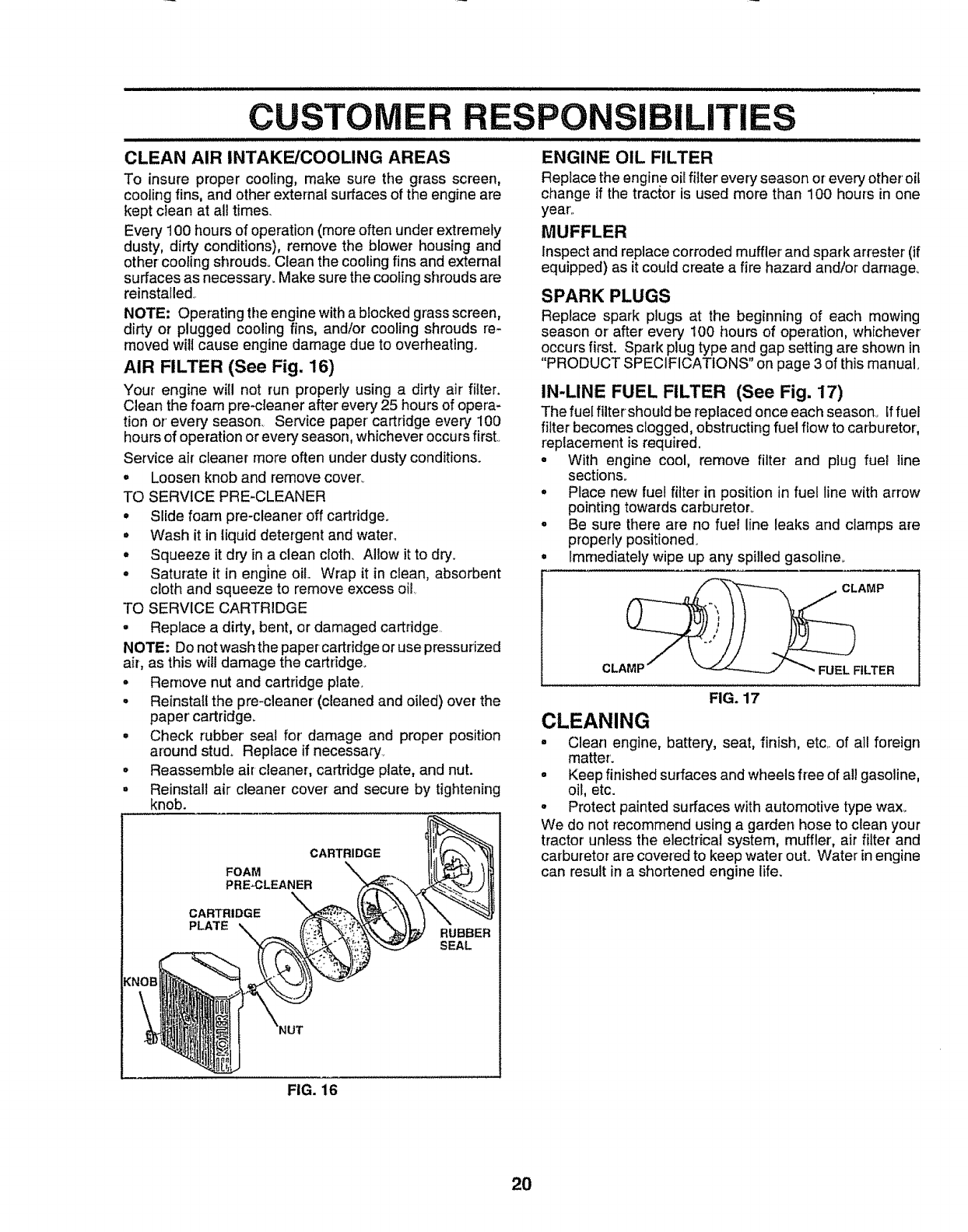
AIR FILTER (See Fig. 16)
Your engine will not run properly using a dirty air fitter.
Clean the foam pro-cleaner after every 25 hours of opera-
tion or every' season_ Service paper cartridge every 100
hours of operation or every season, whichever occurs first.
Service air cleaner more often under dusty conditions.
o Loosen knob and remove cover..
TO SERVICE PRE-CLEANER
° Slide foam pre-cleaner off cartddge.
° Wash it in liquid detergent and water°
o Squeeze it dry in a clean cloth, Allow it to dry.
° Saturate it in engine oil. Wrap it in clean, absorbent
cloth and squeeze to remove excess oil
TO SERVICE CARTRIDGE
•Replace a dirty, bent, or damaged cartridge
NOTE: Do not wash the paper cartridge or use pressurized
air, as this will damage the cartridge..
• Remove nut and cartridge plate.
• Reinstall the pre-cleaner (cleaned and oiled) over the
paper' cartridge.
• Check rubber seal for' damage and proper position
around stud° Replace if necessary.
• Reassemble air cleaner, cartridge plate, and nut.
• Reinstall air cleaner cover and secure by tightening
knob.
CARTRIDGE
FOAM
PRE_CLEANER
CARTRIDGE
PLATE RUBBER
SEAL
................ . II/IIJlLLJIIIJI:Ul/II.
PONSIBILITIES
:/
ENGINE OIL FILTER
Replace the engineoil fitter every season or every other'oif
change if the tractor is used more than 100 hours in one
year'.
MUFFLER
Inspect and replace corroded muffler and spark arrestor (if
equipped) as it could create a fire hazard and/or darnageo
SPARK PLUGS
Replace spark plugs at the beginning of each mowing
season or after every 100 hours of operation, whichever
occurs first. Spark plug type and gap setting are shown in
"PRODUCT SPECIFICATIONS" on page 3 of this manual_
IN-LINE FUEL FILTER (See Fig. 17)
The fuel filter should be replaced once each season_ Iffuel
filter becomes clogged, obstructingfuel flow to carburetor,
replacement is required,
• With engine cool, remove filter and plug fuel line
sections.
• Place new fuel filter in position in fuel line with arrow
pointing towards carburetor.
•Be sure there are no fuel line leaks and clamps are
properly positioned.
Immediately wipe up any spilled gasoline.
CLA_FILTER
FIG. 17
CLEANING
•Clean engine, battery, seat, finish, etc. of all foreign
matter.
= Keep finished surfaces and wheels free of all gasoline,
oil, etc.
•Protect painted surfaces with automotive type wax_
We do not recommend using a garden hose to clean your
tractor unless the electrical system, muffler', air filter and
carburetor are covered to keep water out. Water in engine
can result in a shortened engine life.
FIG. 16
20
ERViCE A ADJUSTMENTS
CAUTION: BEFORE PERFORMING ANY SERVICE OR ADJUSTMENTS:
•Depress clutch!brake pedal fully and set parking brake.
o
o
o
D
Place motion control lever in neutral (N) position,
Place attachment clutch in "DISENGAGED" position.
Turn ignition key "OFF" and remove key,
Make sure the blades and all moving parts have completely stopped.
Disconnect spark plug wire from spark plug and place wire where it cannot come in contact with
plug. ..............
ii_lllllt i
TRACTOR
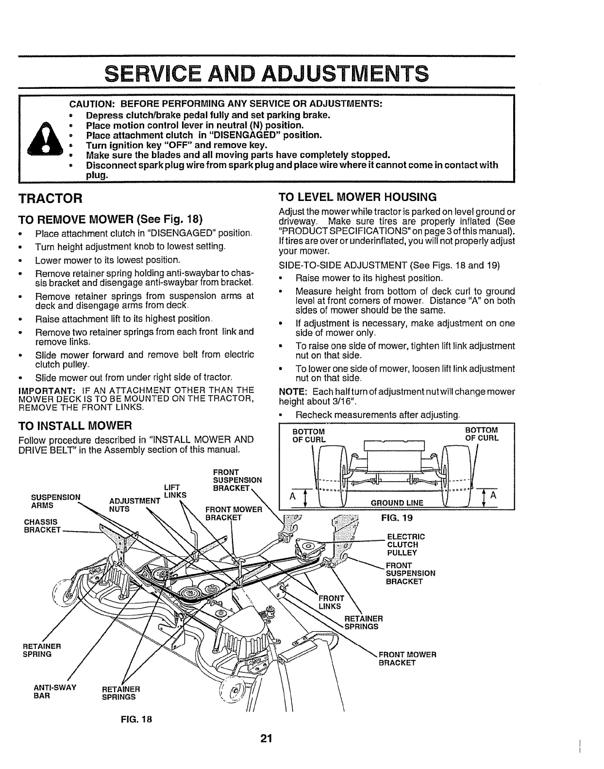
TO REMOVE MOWER (See Fig. 18)
oPlace attachment clutch in"DISENGAGED" position.
= Turn height adjustment knob to lowest setting.
,Lower mower to its lowest position°
-Remove retainer spring holding anti-swaybar to chas-
sis bracket and disengage antt-swaybar from bracket.
,Remove retainer springs from suspension arms at
deck and disengage arms from deck.
°Raise attachment lift to its highest position.
•Remove two retainer springs from each front link and
remove links.
• Slide mower forward and remove belt from electric
clutch pulleyo
o Slide mower out from under right side of tractor°
IMPORTANT; IF AN ATTACHMENT OTHER THAN THE
MOWER DECK IS TO BE MOUNTED ON THE TRACTOR,
REMOVE THE FRONT LINKS..
TO INSTALL MOWER
Follow procedure described in "INSTALL MOWER AND
DRIVE BELT" in the Assembly section of this manual
FRONT
SUSPENSION
LIFT BRACKET
SUSPENSION
ARMS ADJUSTMENT LINKS
NUTS FRONT MOWER "_
BRACKET "_
CHASSIS
TO LEVEL MOWER HOUSING
Adjust the mower while tractor is parked on _evelground or
driveway. Make sure tires are properly inflated (See
"PRODUCT SPECIFICATIONS" on page 3 of this manual).
iftires are over or underinflated, you will not properIy adjust
your mower°
SIDE-TO-SIDE ADJUSTMENT (See Figs. 18 and 19)
• Raise mower to its highest position.
• Measure height from bottom of deck curl to ground
level at front corners of mower. Distance "A" on both
sides of mower should be the same.
° if adjustment is necessary, make adjustment on one
side of mower only,
. To raise one side of mower, tighten lift link adjustment
nut on that side_
° To lower one side of mower, loosen leftlink adjustment
nut on that side.
NOTE: Each half turn of adjustment nutwill change mower
height about 3/16".
, Recheck measurements after adjusting,
BOTTOM BOTTOM
OF CURL OF CURL
A A
FIG. 19
ELECTRIC
CLUTCH
PULLEY
FRONT
SUSPENSION
BRACKET
RETAINER
SPRING ,FRONT MOWER
BRACKET
ANT|-SWAY RETAINER
BAR SPRINGS _=,
FIG. 18
21
iii i iii ill ijl,
SERVICE AND ADJUST ENTS
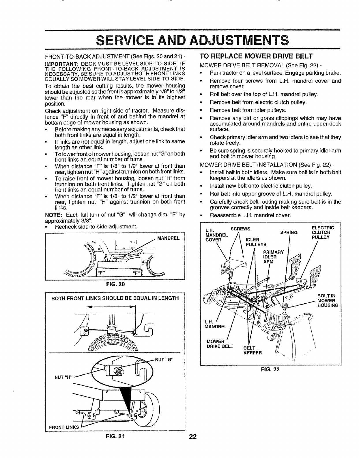
FRONT-TO-BACK ADJUSTMENT (See Figs, 20 and 21) -
IMPORTANT: DECK MUST BE LEVEL SIDE-TO-StDE.. IF
THE FOLLOWING FRONT-TO-BACK ADJUSTMENT IS
NECESSARY, BE SURE TO ADJUST BOTHFRONT LINKS
EQUALLY SO MOWER W_LLSTAY LEVEL SIDE-TO-StDEo
To obtain the best cutting results, the mower housing
should be adjusted so the front is approximately 1/8" to 1/2"
lower than the rear when the mower is in its highest
position..
Check adjustment on right side of tractor,. Measure dis-
tance "F" directly in front of and behind the mandrel at
bottom edge of mower housing as shown°
•Before making any necessary adjustments, check that
both front links are equal in length.,
• If links are not equal in length, adjust one link to same
length as other link.
• To Iowerfront of mower housing, loosen nut"G"on both
front links an equal number of turns,
° When distance "F" is 1/8" to 1/2" lower at front than
rear, tighten nut"H" against trunnion on both front links.
.To raise front of mower housing, loosen nut "H" from
trunnion on both front links. Tighten nut "G" on both
front links an equal number of turns.
°When distance "F" is !/8" to 1/2" lower at front than
rear', tighten nut "H" against trunnion on both front
links°
NOTE: Each full turn of nut "G" will change dim_ "F"by
approximately 3/8".
° Recheck side-to-side adjustment°
FIG, 20
BOTHFRONT LINKSSHOULDBE EQUALIN LENGTH
FRONTLtNKS
TO REPLACE MOWER DRIVE BELT
MOWER DRIVE BELT REMOVAL (See Fig. 22) -
•Park tractor on a level surface, Engage parking brake_
° Remove four screws from L.H_ rnandret cover and
remove cover,,
= Roll belt over the top of L.H, mandrel pulley.
•Remove belt from electdc clutch pulley.,
•Remove bert from idler pulieys_
• Remove any dirt or grass clippings which may have
accumulated around mandrels and entire upper deck
surface.
•Check primary idler' arm and two idlersto see that they
rotate freely,,
= Be sure spring is securely hooked to primary idler arm
and bolt in mower housing.,
MOWER DRIVE BELT INSTALLATION (See Fig 22) -
° Install belt in both idlers. Make sure belt is in both belt
keepers at the idler's as shown°
• Install new belt onto electric clutch pulley_
° Roll belt into upper' groove of L.H. mandrel pulley.
•Carefully check belt routing making sure belt is in the
grooves correctly and inside belt keepers.
• Reassemble L.H.,mandrel cover'..
ELECTRIC
L,Ho SCREWS SPRING CLUTCH
MANDREL PULLEY
COVER IDLER
PULLEYS
PRIMARY
IDLER
ARM
BOLT IN
MOWER
HOUSING
MANDREL
MOWER
DRIVE BELT BELT
KEEPER
FIG. 22
FIG. 21 22
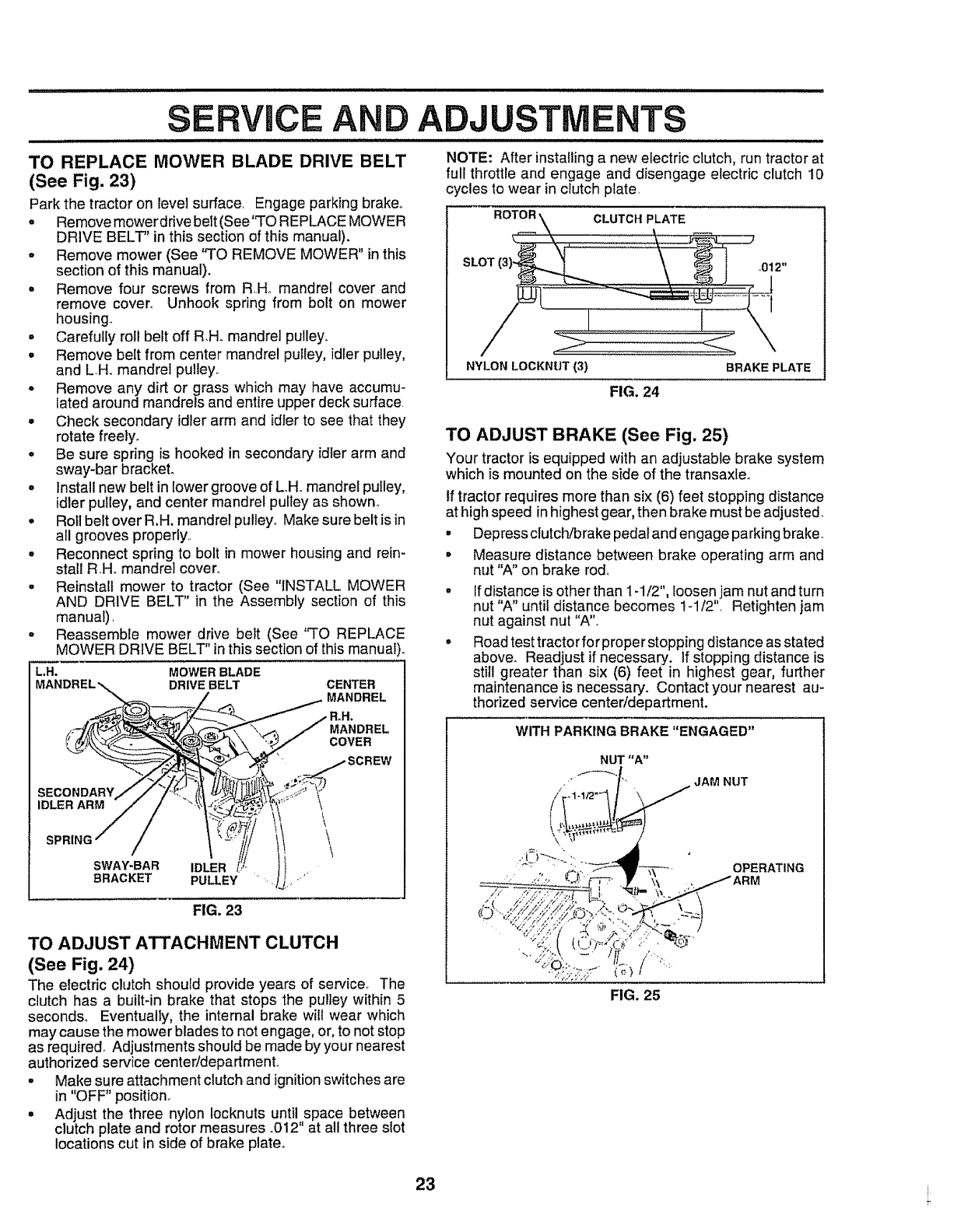
;ERVmCEAND A
mini = u m re=l= i iH i= i = =ll=l= i i =l i=ll,==, =lHi, ,= =,ll i = i= H
o
L.H.
TO REPLACE MOWER BLADE DRIVE BELT
(See Fig. 23)
Park the tractor on level surface. Engage parking brake.
oRemovemower drive belt(See'q'O REPLACE MOWER
DRIVE BELT" in this section of this manual),
= Remove mower (See "TO REMOVE MOWER" inthis
section of this manual).
= Remove four screws from RHo mandrel cover and
remove cover,, Unhook spring from bolt on mower
housing_
•Carefully roll belt off R,H. mandrel pulley.
=Remove belt from center mandrel pulley, idler pulley,
and LH. mandrel puleyo
=Remove any dirt or grass which may have accumu-
lated around mandrels and entire upper deck surface,
•Check secondary idler arm and idrer to see that they
rotate freely°
=Be sure spring is hooked in secondary idler arm and
sway-bar bracket.
o install new belt in lower groove of LH. mandrel pulley,
idler pulley, and center mandrel pulley as shown.,
=Roll belt over R,H, mandrel pulley° Make sure belt is in
all grooves properly.
°Reconnect spring to bolt in mower housing and rein-
stall R.H,, mandrel cover.
° Reinstall mower to tractor (See "INSTALL MOWER
AND DRIVE BELT" in the Assembly section of this
manual),
Reassemble mower drive belt (See "TO REPLACE
MOWER DRIVE BELT" inthis section of this manual).
CENTER
MANDREL
MOWER BLADE
DRIVE BELT
USTMENTS
llmHi iml mllll i ii ii iH llllll ii i i ii
NOTE: After installinga new electric clutch, run tractor at
full throttle and engage and disengage electric clutch 10
cycles to wear in clutch plate,
CLUTCH PLATE
NYLON LOCKNUT (3)
FIG. 24
BRAKE PLATE
TO ADJUST BRAKE (See Fig. 25)
Your tractor is equipped with an adjustable brake system
which is mounted on the side of the transaxte.
tf tractor requires more than six (6) feet stopping distance
at high speed inhighest gear, then brake must be adjusted.
°Depress clutch/brake pedal and engage parking brake..
°Measure distance between brake operating arm and
nut "A" on brake rod.
If distance is other than 1-1/2", loosen jam nut and turn
nut "A" untit distance becomes 1-1/2", Retighten jam
nut against nut "A'L
Road test tractorfor proper stopping distance as stated
above. Readjust if necessary. If stopping distance is
still greater than six (6) feet in highest gear, further
maintenance is necessary. Contact your nearest au-
thorized service center/department.
MANDREL
COVER
IDLER ARM
SWAY-BAR IDLER
BRACKET PULLEY ",.
\\\
FIG. 23
TO ADJUST ATTACHMENT CLUTCH
(See Fig. 24)
The electric clutch should provide years of service. The
clutch has a buit-in brake that stops the puley within 5
seconds° EventualIy, the internal brake wil wear which
may cause the mower blades to not engage, or,to not stop
as required_ Adjustments should be made by your nearest
authorized service center/department.
° Make sure attachment clutch and ignition switches are
in "OFF" position.
° Adjust the three nylon Iocknuts until space between
clutch plate and rotor measures .012" at all three slot
locations cut in side of brake plate.,
WITHPARKING BRAKE "ENGAGED"
NUT "A"
Jf
/"/-----_._, JAM NUT
/.1-1/2 "_ \
OPERATING
FIG. 25
23 i
SERVICE AND ADJU
i =l= i=l=l=Hl=l .......................................
TO REPLACE MOTION DRIVE BELT
(See Fig. 26)
Park the tractor on level surface,. Engage parking brake_
For ease of service there is a belt installationguide decal on
bottom of left footrest.
o Remove mower (See 'q'O REMOVE MOWER" in this
section of this manual.)
BELT REMOVAL
= Engage parking brake (creates slack in belt)_
• Remove bert from clutching and fan idler pulleys..
°Loosen belt keeper above transaxle pulley.
° Remove belt from transaxie pulley_
° Remove belt from engine pulley and front V-idler pul-
ley.,
° Pull belt out of all belt keepers and remove from tractor°
BELT INSTALLATION -
• Place V part of belt into grooves on engine pulley and
front V-idler, making sure to route belt inside of all belt
keepers.,
•Route belt on right side, coming from V-idler, towards
back of tractor, above midspan belt keeper' and to top
of transaxle pulley.
° Route belt on left side, coming from engine pulley,
towards back of tractor and through loop in mldspan
belt keeper.
=Place V part of belt into grooves on transaxle and fan
idterpulleys, making sure to route belt insideof all belt
keepers°
° Retighten belt keeper above transaxle pulley.
•Place belt around clutching idlers as shown, making
sure to route belt inside of all belt keepers.,
-Check to be sure belt is positioned correctly and is on
proper side of art belt keepers.
o Reinstall mower,.
IMPORTANT; CHECK BRAKE ADJUSTMENT.
TRACTOR V-BELTDRIVE SCHEMATIC
VIEWED FROM L.H. SIDE OF TRACTOR
CLUTCHING TRANSAXLE
BELT PULLEY
KEEPER
ENGINE
PULLEY
V-IDLER KEEPER
KEEPER BELT
TWISTS BELT FAN
KEEPER IDLER
AS VIEWED FROM BOTTOM
TO ADJUST MOTION CONTROL LEVER
(See Fig. 27)
The motion control leverhas been presetat the factory and
adjustment should not be necessary_
If for any reason the motion control lever will not hold its
positionwhile at aselected speed, itmay be adjusted at the
friction pack located on the right side of chassis,
• Park tractor on level surfacer Stop tractor by turning
ignition key to "OFF" position and engage parking
brake_
=Place motion control lever in neutral (N) position_
o While holding locknut, toosen jam nut
°Tighten tocknut 1/4 turn,
•White holding Iocknut, tighten jam nut securely_
NOTE: if for any reason the effort to move the motion
control lever becomes too excessive, reverse the above
adjustment procedure by loosening iocknut 1/4 turn_
Road test tractor after adjustment and repeat procedure if
necessary_
LOCKNUT
,JAM NUT
FIG. 27
TRANSMISSION REMOVAL/REPLACEMENT
Should your transmission require removal for service or
replacement, itshould be purged after reinstallation before
operating the tractor. See "PURGE TRANSMiSSiON" in
Operation section of this manual,
TO ADJUST STEERING WHEEL ALIGNMENT
if steering wheel crossbars are not horizontal (left to right)
when wheels are positioned straight forward, remove steer-
ir_,gwheel and reassemble per instructions in the Assembly
section of this manual
FIG. 26 24
o
o
RVICE AND ADJUSTMENTS
ill ill ii i i i ..................
FRONT WHEEL TOE-IN ADJUSTMENT
Front wheel toe-in is required for proper steering operation,,
Toe-in was set at the factory and adjustment should not be
necessary,, If parts in the front axfe or steering mechanism
have been replaced or damaged, check toe-in and adjust
if necessary.
TO CHECK TOE-IN (See Fig,,28) -
= Position front wheels straight ahead.
• Measure distance between wheels at front and rear of
tires (dimensions "A" and "B").
=Front dimension "A" should be 1/8" to 1/4" less than
rear dimension "B",,
TO ADJUST TOE-IN (See Figs, 28 and 29) -
- Loosen jam nuts at adjustment sleeves on tie rod°
Adjust tie rod until dimension"A" is 1/8" to 1/4" less than
dimension "B".
WAS1
RETAINING
RING
AXLE
COVER
FIG. 30
NOTE: To seal tire punctures and prevent flat tires due to
slow leaks, tire sealant may be purchased from your local
parts dealer.. Tire sealant also prevents tire dry rot and
corrosion°
TO START ENGINE WITH A WEAK BATTERY
(See Fig. 31)
Tighten jam nuts securely.
_A _
FIG. 28
JAM NUTS _'_ _
TIE ROD
ADJUSTMENT
SLEEVES
FIG. 29
FRONT WHEEL CAMBER
CAUTION: Lead-aci"d"'b'atteriesgen'er':.....
ateexpiosivegases. Keepsparks, flame
and smoking materials away from bat-
teries. Always wear eye protection
when around batteries,
LL/lll.l,,J.l.Jl/llJllll Illll I I I HI
If your battery is too weak to start the engine, it should be
recharged° If "jumper cables" are used for emergency
starting, folrow this procedure:
IMPORTANT: YOUR TRACTOR IS EQUIPPED WiTH A I2
VOLT NEGATIVE GROUNDED SYSTEM., THE OTHER
VEHICLE MUST ALSO BE A 12 VOLT NEGATIVE
GROUNDED SYSTEM. DO NOT USE YOUR TRACTOR
BATTERY TO START OTHER VEHICLES°
TO ATTACH JUMPER CABLES -
• Connect each end of the RED cable to the POSITIVE
(+) terminal of each battery, taking care not to short
against chassis.
• Connect one end of the BLACK cable to the NEGA-
TIVE (-) terminal of fully charged battery°
° Connect the other end of the BLACK cable to good
CHASSIS GROUND, away from fuel tankand battery,,
TO REMOVE CABLES, REVERSE ORDER -
•BLACK cable first from chassis and then from the fully
charged battery.
•RED cable last from both batteries_
The front wheel camber is not adjustable on your tractoro if
damage has occurred to affect the front wheel camber,
contact your nearest authorized service center/depart-
ment,,
TO REMOVE WHEEL FOR REPAIRS
FRONT WHEEL (See Fig,,30) -
° Block up axle securely.
. Remove axle cover, retaining ring and washersto allow
wheel removal.
° Repair tire and reassemble°
• Replace washers and snap reta{ning ring securely in
axle groove.
°Replace axle cover_
REAR WHEEL -
- Block rear axle securely,
°Remove five (5) hub bolts to allow wheel removal
• Repair tire and reassemble, Replace and tighten hub
bolts securely. 25
"POSITIVE" {+) "NEGATIVE" (-)
LH. PANEL
LT
.................//
FIG. 31
SERVICE AND ADJ
TO REPLACE HEADLIGHT BULB
•Raise hood,
• Puff bulb holder out of the hole inthe backside of the
gritL
° Replace bulb in holder' and push bulb holder securely
back into the hole in the backside of the griH_
° Close hood.
° Raise hood°
•Unsnap headlight wire connector.
° Stand in front of tractor° Grasp hood at sides, tiff toward
engine and lift off of tractor.
° To replace, reverse above procedures.
INTERLOCKS AND RELAYS
Loose or damaged wiring may cause your tractor to run
poorly, stop running, or prevent it from starting.
• Check wiring° See electrical wiring diagram in the
Repair Parts section of this manual.
TO REPLACE FUSE
Replace with 30 amp automotive-type plug-in fuse. The
fuse holder is located behind the dash,
TO ADJUST ATTACHMENT LIFT SPRING
(See Fig, 32)
• While holding spring bushing with wrench, loosen jam
nut..
• Turn adjustment bolt clockwise to extend spring and
reduce lift effort for heavier attachments°
.Turn adjustment bolt counterclockwise for' lighter' at-
tachments.
°Retighten jam nut against spring bushing.
IMPORTANT, DO NOT ADJUST FOR MAXIMUM SPR{NG
TENSION WHEN USING LIGHT ATTACHMENTS SUCH
AS A MOWER, ADJUST LIFT LEVER SPRING TO AID IN
LIFTING ATTACHMENT. DO NOT OVERPOWER SPRING.
WHEN REMOVING ATTACHMENT, ALWAYS ADJUST
SPRING TENSION TO ITS LOWEST POSITION_
TO REMOVE HOOD AND GRILL ASSEMBLY
See Fig, 33)
ADJUSTMENT SPRING BUSHING
oATTACHMENT
JAM NUT LIFT SPRING
o_
/_ i;%,,
•: s
HOOD
HEADLIGHT
WIRE
CONNECTOR
FIG. 33
ENGINE
TO ADJUST THROTTLE CONTROL CABLE
(See Fig, 34)
The throttle control has been preset at the factory and
adjustment should not be necessar¥_ Check adiustment as
described below before loosening cable° If adjustment is
necessary', proceed as follows:
°With engine not running, move throttle control lever to
fast position.
°Check that speed contro! lever is against stop screw. If
it is not, loosen casing clamp screw and pull throttle
cable until lever is against screw_ Tighten clamp screw
securely_
FIG. 32
26
IDLE FUEL
ADJUSTING
NEEDLE
IDLE SPEED
SCREW
THROTTLE
CONTROL
CABLE
CHOKE
CONTROL
CABLE
STOP CLAI
SCREW SCREW
FIG. 34
TO ADJUST CHOKE CONTROL
(See Figs. 34 and 35)
The choke control has been preset at the factory and
adjustment should not be necessary, check adjustment as
described below before loosening cabie_ If adjustment is
necessary, proceed as follows:
•With engine not running, move choke control (located
on dash panel) to full choke position.
- Remove air cleaner cover, filter and cartridge plate to
expose carburetor choke (See "AIR FILTER" in the
Customer Responsibilities section of thfs manual)_
o Choke should be closed. If it is not, loosen casing
clamp screw and move choke cable until choke is
coml_letely closed. Tighten casing clamp screw se-
curely,.
°Reassemble air cleaner.
CLOSED FOR
TO ADJUST CARBURETOR (See Fig. 34)
The carburetor has been present at the factory and adjust_
ment should not be necessary_ However, minor adjustment
may be required to compensate for differences in [uel,
temperature, altitude or Ioado If the carburetor does need
adjustment, proceed as follows:
in general, turning the adjusting needles in (clockwise)
decreases the supply of fuel to the enginegiving a leaner
fuel/air mixture° Turning the adjusting needles out (coun-
terclockwise) increases the supply of fuel to the engine
giving a richer fuel/air mixture.
IMPORTANT: DAMAGE TO THE NEEDLES AND THE
SEATS IN CARBURETOR MAY RESULT IF SCREW IS
TURNED IN TOO TIGHT
PRELIMINARY SETTING -
• Be sure you have a clean air filter, and the throttle
control cable is adjusted properly (see 'q'O ADJUST
THROTTLE CONTROL CABLE" in the Service and
Adjustments section of this manual)..
- With engine off turn idle fuel adjusting needle in (clock-
wise) closing itfinger tight and then turn out (counter-
clockwise) 1 turn°
FINAL SETTING -
.Start engine and allow to warm for five minutes. Make
final adjustments with engine running and shift/motion
control lever in neutral (N) position.
°The high idle is set at the factory and cannot be
adjusted°
= Idle speed setting - With throttle control lever in slow
position, engine should idle at 1200 RPM. If engine
idles tooslow or fast, turn idle speed adjusting screw in
or out until correct idle is attained.
-idle fuel nee,die setting - With throttle control lever in
slow position,turn idle fuel adjusting needle in (clock-
wise) until engine speed decreases and then turn out
(counterclockwise) approximately 3/4 turn to obtain the
best low speed performance_
•Recheck idle speed. Readjust if necessary.
ACCELERATION TEST -
°Move throttle control lever from slow to fast position. If
engine hesitates or dies, turn idlefuel adiusting needle
out (counterclockwise) 1/8 turn,. Repeat test and con-
tinue to adjust, if necessary, until engine accelerates
smoothly.
High speed stop isfactory adjusted. Do not adjust-damage
may result°
IMPORTANT: NEVER TAMPER WITH THE ENGINE
GOVERNOR, WHICH IS FACTORY SET FOR PROPER
ENGINE SPEED.. OVERSPEED1NG THE ENGINE ABOVE
THE FACTORY HIGH SPEED SETTING CAN BE
DANGEROUS. tF YOU THINK THE ENGINE-GOVERNED
HIGH SPEED NEEDS ADJUSTING, CONTACT YOUR
NEAREST AUTHORIZED SERVICE CENTER/
DEPARTMENT, WHICH HAS PROPER EQUIPMENT AND
EXPERIENCE TO MAKE ANY NECESSARY
ADJUSTMENTS°
FIG, 35
27 J
STORAGE
Immediately prepare your tractor for storage at the end of
the season or if the tractor will not be used for 30 days or
more.
...................... IIIIII III IIIII
i_ CAUTION: Never storethe tractor with
gasoline in the tank inside a building
where fumes may reach an open flame
or spark. Allow the engine to cool
before storing in any enclosure.
..................................... UnU/I
TRACTOR
Remove mower from tractor for winter storage,, When
mower is to be stored for a period of time, clean it thor-
oughly, remove all dirt, grease, leaves, etc. Store in a
clean, dry area.
• Clean entire tractor (See "CLEANING" inthe Customer
Responsibilities section of this manual),
• Inspect and replace belts, if necessary (See belt re-
placement instructions in the Service and Adjustments
section of this manual)_
•Lubricate as shown in the Customer Responsibilities
section of this manual.
° Be sure that all nuts, bolts and screws are securely
fastened. Inspect moving partsfor damage, breakage
and wear. Replace if necessary.
• Touch up all rusted or chipped paint surfaces; sand
lightly before painting.
BATTERY
•Fully charge the batteryfor storage,
•After a period of time in storage, battery may require
recharging_
. To help prevent corrosion and power leakage during
long periods of storage, battery cables should be
" _ O
d_sconnected and battery cleaned thoroughly (see q"
CLEAN BATTERY AND TERMINALS" in the Cus-
tomer Responsibilities section of this manual).
° After cleaning, leave cables disconnected and place
cables where they cannot come in contact with battery
terminals.
• Be sure battery drain tube is securely attached,
°If battery is removed from tractor for storage, do not
store battery directly on concrete or damp surfaces°
ENGINE
FUEL SYSTEM
IMPORTANT: IT IS iMPORTANT TO PREVENT GUM
DEPOSITS FROM FORMING 1N ESSENTIAL FUEL
SYSTEM PARTS SUCH AS CARBURETOR, FUEL FILTER,
FUEL HOSE, OR TANK DURING STORAGE. ALSO,
EXPERIENCE INDICATES THAT ALCOHOL BLENDED
FUELS (CALLED GASOHOL OR USING ETHANOL OR
METHANOL) CAN ATTRACT MOISTURE WHICH LEADS
TO SEPARATION AND FORMATION OF ACIDS DURING
STORAGE. ACIDIC GAS CAN DAMAGE THE FUEL
SYSTEM OF AN ENGINE WHILE IN STORAGE
°Drain the fuel tank.
• Start the engine and let it run until the fuel lines and
carburetor are empty,
= Never use engine or carburetor cleaner products in the
fuel tank or permanent damage may occur_
° Use fresh fuel next season.
NOTE: Fuel stabilizer is an acceptable alternative in
minimizing the formation of fuel gum deposits during stor-
age. Add stabilizer to gasoline in fuel tank or storage
container° Always follow the mix ratio found on stabilizer
container. Run engine at least 10 minutes after adding
stabilizer to aIlow the stabilizer to reach the carburetor. Do
not drain the gas tank and carburetor if using fuel stabilizer.
ENGINE OIL
Drain oil (with engine warm) and replace with clean engine
oil_ (See "ENGINE" in the Customer Responsibilities
section of this manual),
CYLINDERS
°Remove spark plug(s),,
°Pour one ounce of oil through spark plug hole(s) into
cylinder(s),
=Turn ignition key to"START" positionfor a few seconds
to distribute clio
°Replace with new spark plug(s)_
OTHER
•Do not store gasotine from one season to another,
•Replace your gasoline car] if your can starts to rusL
Rust andtor dirt in your gasoline will cause problem&
= If possible, store your tractor indoors and cover it to
give protection from dust and dirt,
•Cover your tractor with a suitable protective cover that
does not retain moisture Do not use plastic. Plastic
cannot breathe which allows condensation to form and
will cause your tractor to rusL
IMPORTANT: NEVER COVER TRACTOR WHILE ENGINE
AND EXHAUST AREAS ARE STILL WARM.
28

i iiIIJJLJLJlLIIjLIIIl_lU
TROUBLESHOOTI POINTS
PROBLEM
Wilt not start
Hard to start
Engine will not turn over
Engine clicks but will not
start
Loss of power
CAUSE
1. Out of fuel.
2. Engine net"CHOKED" properly=,
3, Engtne flooded,
4 Bad spark plug,
5Dirty air filter,,
6. Dirty fuel filter.,
7, Water in fuel
8. Loose or damaged wiring
9. Carburetor out of adjustment,
10. Engine valves out of adjustment,
1 Dirty air _ter.
2 Bad spark plug_
3Weak or dead battery.
4 Dirty fuel filler_,
5 Stale or dirty fuel.
6, Loose or damaged wiring.
7, Carburetor out of adjustment_
B, Engine valves out of adjustment
1, Clutch/brake pedal not depressed..
2. Attachment clutch is engaged
3 Weak or dead battery.
4, BIown fuse
5 Corroded battery terminals
6 Loose or damaged wldng.
7 Faulty ignition switch
8Faulty solenoid or starter.
9 Faulty operator presence switch(as).
t. Weak or dead battery,,
2Corroded battery terminals.
3, Loose or damaged wiring,
4 Faulty solenoid or starter
1
2,
3
4
5
Culling too much grass'too fast, 1..
Throttle in "CHOKE" position. 2,
Build-up of grass, leaves and trash under mower 3
Dirty air |i]ter. 4,
Low oil levelld_rty oil 5.
CORRECTION
1, Fill fuel tank
2 See "TO START ENGINE" in Operation section.
3, Wait several minutes before altempting to start
4, Replace spark plug,,
5 Clean/replace air filter..
6. Replace fuel filter,
7, Drain fuel tank and carburetor, refill tank with fresh
gasoline and replace fuel filter.
8., Check alt wiring.
9,, See "To Adjust Carburetor" in Service Adjustments
section..
t0, Contact an authorized ser_tca center/department
1 Clean!replace air filter
2. Replace spark plug
3. Recharge or replace battery,
4 Replace fuel filter
5, Drain fiJel tank and refifl with fresh gasoline
6, Check all wiring.
7 See "To Adjust Carburetor" in Service Adjustments
section
8. Contact an authorized service center/department.
1,, Depressclutch/brake pedal,
2.. Disengage attachment clutch,
3Recharge or replace batlery.
4, Replace fuse,,
5 CIean battery terminals
6. Check a!l wiring
7. Chectdreplace ignition swilch
8, Chectdreplaca solenoid or starter,
9. Contact an authorized service centerldepartmenL
I. Recharge or replace battery,
2., Clean battery terminals.
3 Check alt wiring,
4, Check/replace solenoid or starter
Set in "Higher Cut" position/reduce speed,
Adjust throttle control
Clean underside of mower housing,
Clean/replace air filter
Check oil leveltchange oil,
Excessive vibration
6, Faulty spark plug.
7, Dirty fuel filter.
8. Stale or dirty fuel,
9 Water in fuel,
10, Spark plug wire loose.
11_ Dirty engine air screen/tins
12, Dirtylclogged muffler_,
13 Loose or damaged wiring.
t4 Carburetor out of adjustment
t5 Engine valves out of adjustment
Worn, bent or loose blade
2 Bent blade mandrel
3 Looseldamaged part(s),
6, Clean and regap or change spark plug
7o Replace fuel filter.
8r Drain fuel tank and refill with fresh gasoline,
9 Drain fuel tank and carburetor, refill tank with fresh
gasoline and replace fuel filter,
10, Connect and tighten spark plug wire,
11. Clean engine atr screerdfins
12 Cleantreplace muffler,
13 Check alt wiring.
14. See "To Adjust Carburetor" in Service Adjustments
section.
t5, Contact an authorized service center/department
1, Replace blade. Tighten blade bolt.
2, Replace blade mandrel.
3 Tightenloose part(s), Replace damaged parts,
29

LIJll,Jl
PROBLEM
TROUBLESHOOTI POINTS
................... , ,,,,,,,,,,,,,,,,,,,,,,,,,,,,,,,,,,,,
CORRECTION
Engine continues to run
when operator leaves seat
with attachment clutch
engaged
Poorcut-uneven
ill,i,
Mower blades will not
rotate
Poor grass discharge
Headlight(s) not working
(if so equipped)
Battery will not charge
ill i,ii, i ii ii,lllllll
Engine "backfires"
when turning engine
"OFF"
CAUSE
1 Faulty operator-safety presence control system,
1, Worn, bent or loose bEade
2. Mowerdeck not level.
3. Buildup of grass, leaves, and trash under mower
4 Sent blade mandrel,
5Clogged mower deck vent holes from buildup of
grass, leaves, and trash around mandrels.
"L Check wiring, switches and connections. If not
corrected, contact an authorized service center/
depadment
1
2
3. Frozen idler puliey
4 Frozen blade mandrel.
Obstruction in clutch mechanism.
WomJdamaged mower drive belt.
t, Replace blade Tighten btade bolt
2.. Level mower deck,
3 Clean underside of mower housing,.
4 Replace blade mandrel
5 Clean around mandrels to open vent holes.
1Remove obstruction.
2, Replace mower drive belt
1. Engine speed too slow
2. Travel speed too fast
3. Wet grass
4_ Mower deck not level.
5. Lowluneven tire air pressure,
3Replace idler pulley
4, Replace blade mandrel
1 Place throttlecontro_ in "FAST" position
2Shift to slower speed.
3Altow grass to dry before mowing
4, Levelmower deck
5. Check tires for proper air pressure,
6, Worn, bent or loose blade
7, Buildup of grass, leaves and trash under mower.
8. Mowerddve beftworn.
9. Btadesimpropedytnstalled.
10. lmproperblades used,
11, Clogged mower deck vent holes from buildup of
grass, leaves, and trash around mandrels
1. Switch is "OFF"
2 Bulb(s) burned out
3Faulty light switch
4. Loose or damaged wiring_
5, Blown fuse
i, ,i
1,. Bad ba/tery celt(s).
2. Poor cable connections
3,, Faulty regulator (if so equipped)
4.. Faulty alternator..
6. Replace/sharpen blade Tighten biade bolt
7. Clean underside of mower housing.
8. Replace mower drive belt..
9. Reinstafl blades sharp edge down
10. Replace with blades listed in this manuaI
11 Clean around mandrels to open vent holes
1, Tum switch "ON".
2Replace bulb(s}_
& Check/replace light switch
4 Checkwiring and connections
5 Replace fuse
I. Replace battery
2 Check/clean all connections..
3, Replace regulator_
4. Replace alternator
1., Freewheel control in "disengaged" position
2. Motion drive belt worn, damaged, or broken
3. A{r trapped in transmission during shipment
or servicing.
HI
1. Place freewheel control in "engaged" positior_
2 Replace motion drive boil
3. Purge transmission
t,. Engine throttle control not set at "SLOW"
position for 30 seconds before stopping engine
1,. Move throttle control to "SLOW" position and altow
to idle for-30 seconds before stopping engine,
30
TRACTOR -- MODEL NUMBER 917.258911
IGNITION SWITCH
POSITION CIRCUIT "MAKE"
OFF :G+M+L NI3NE
RUt_UGHT ,,,B+L,,, A,,+Y
RUN ........ B+L ,,, NONE
START B + L + S NONE
OWN ELECTRICAL SOURCE,
WILL CHANGE WITH ENGINE
!
l
I
!
!
t
)
t
WIRING INSULATED CLIPS
NOTE: IF WIRING INSULATED
CLIPS WERE REMOVED FOR
SERVICING OF UNIT, THEY
SHOULD BE REPLACED TO
PROPERLY SECURE YOUR
WIRING.
BECAUSE OF THIS, THE
BRIGHTNESS OF THE LIGHTS
SPEED. AT IDLE THE LIGHTS
WILL DIM. AS THE ENGINE IS
SPEEDED UP, THE LIGHTS
WILL BECOME THEIR BRIGHTEST.
ENGINE CONNECTOR
HEADLIGHTS G FC
PTO SWITCH_-- [_ _'_--I
PosmoN CiRCU_
.... OFF C--G,":H H
..............ON g+ F_ B+ E,A,+ D
DA
O ti
REMOVABLE NON-REMOVABLE
CONNECTIONS CONNECTIONS
TRACTOR CONNECTOR
IGNmON SWITCH
REGULATOR ENGINE
(PUFIPLE WIRE, \ISHORTING
REDWIRE) _ (£'VHITEWIRE) SHORTING _ _ (REDWIRE")
(_CKW,RE)II_ _ II
CARBURETOR 11_._---1_11
SOLENOID Itr-"_=tl N¢ OILSENTRY lt_ I_--Itl SWITCHED
(REDWIRE __I_T-ff||_-_J_L-O1LSE RY OPTION _ _ +12V
BLUE WIRE) -- _ (GREEN WIRE) (YELLOW WIRE _ (BLLIE WIRE)
TO LIGHT PKG )
31
REPAIR PARTS
ELECTRICAL
TRACTOR - - MODEL NUMBER 917.258911
22
/
I I
I I
I I
I I t
l
l
t
I
I
I
16
2o
/
/
I
1 3
19
20
I
I
jP
33
I
/
/
\
32
31
3
I
l
t
t
I
1
/
I
I
I
I
32
REPAIR PARTS
TRACTOR --MODEL NUMBER 917.258911
KEY PART
NO. NO. DESCRIPTION
1 144927 Battery
2 74760412 Bolt Hex Head 1/4-20 x 3/4
3 STD551125 Washer, Lock 1/4
4 STD551025 Washer 9/32 x 5/8 x 16 Ga
6 STD541025 Nut Fin Hex 1/4-20
7 7697J Tube Plastic
8 7603J Tray, Battery
9109596X Clamp, Hose
10 145211 Bolt Wet BTR 1/4-20 x 7°5 Zinc
11 150109 Hold down Battery Front Mount
12 145769 Nut Push Nylon 1/4" Wet Battery
16 153664 Switch IntedockPush-ln
19 STD551125 Washer, Lock 1/4
20 73350400 Nut, Jam Hex 1/4-20
21 136850 Harness Socket LightW/4152J
22 4152J Bulb Light
24 4014J Cable Battery 4 Gao22" Red
25 146686 Cable Battery Red 4 Ga. w/16 Wire
26 t08824X Fuse
28 157899 Cable Battery 4 Gauge 3/8 Term
29 160784 Switch, Plunger
30 140301 Switch, Ign
31 124211X Nut, ignition Switch
32 141226 Cover Switch Key
33 109310X Key .
40 160732 Harness Ign.
41 17720408 Screw t/4-20 x 1/2
42 131563 Cover, Terminal Red
43 145673 Solenoid
45 122822X Ammeter
46 110940X Meter, Hour
47 17011008 Screw
50 154963 Switch, PTO
51 140405 Ring Retainer PTO
81 109748X Reiay Asm.
NOTE: All component dimensions given in U.So inches
1 inch = 25°4 mm
33
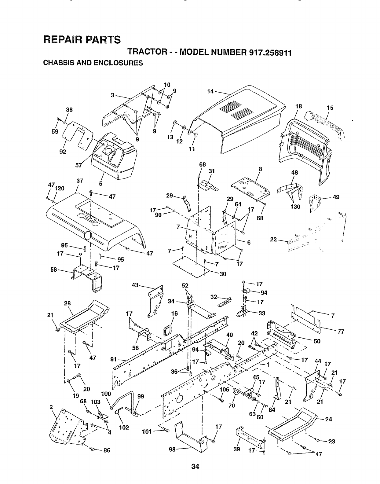
REPAIR PARTS
TRACTOR- - MODEL NUMBER 917.258911
CHASSIS AND ENCLOSURES
38
59
92
47120
57
37
11
14
I
17 16
52
56
64
7O
8
17/
68
17
4
42
_o
45
18 15
48
130
34
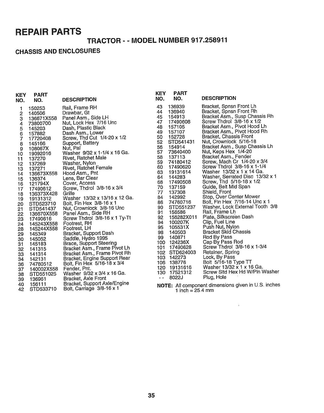
REPAIR PARTS
TRACTOR - - MODEL NUMBER 917.258911
CHASSIS AND ENCLOSURES
KEY PART KEY PART
NO. NO. DESCRIPTION NO. NO. DESCRIPTION
1 150253 Rail, Frame RH 43 136939
2 140506 Drawbar, Gt 44 136940
3 136671X558 PanelAsm, Side LH 45 '154913
4 73800700 Nut, Lock Hex 7/16 Unc 47 17490608
5 145203 Dash, Plastic Black 48 157105
6 '157882 Dash Asm,., Lower 49 157107
7 17720408 Screw, Thd Cut 1/4-20 x 1/2 50 152728
8 145166 Support, Battery 52 STD54143t
9 108067X Nut, Pal 56 154914
10 t9092016 Washer 9/32 x 1-1/4 x 16 Gao 57 73640400
11 137270 Rivet, Ratchet Male 58 137113
12 137269 Washer, Nylon 59 74180412
13 137271 Rivet, Ratchet Female 60 17490620
t4 136673X558 HoodAsm., Pnt 63 19131614
15 136374 Lens, Bar Clear 64 144283
16 121794X Cover, Access 68 17490508
17 17490612 Screw, Thdrol 3/8-t6 x 3/4 70 137159
18 136373X428 Grille 77 137308
19 19131312 Washer 13/32 x 13/16 x 12 Gao 84 142992
20 STD523710 Bolt, Fin Hex 3/8-16 x I 86 74760716
21 STD541437 Nut, Crownlock 3/8-I6 Unc 90 STD551237
22 136670X558 PanefAsm_, Side RH 91 156586
23 17490616 Screw Thdrol 3/8-16 x 1 Ty-Tt 92 156282X011
24 t45243X558 Footrest, RH 94 100207K
28 145244X558 Footrest, LH 95 105531X
29 145349 Bracket, Support Dash 98 140503
30 145052 Saddle, Hydro 1995 99 14087'1
3t 145183 Brace, Support Steering 100 124236X
32 141315 Bracket Asm., Frame Pivot Lh 101 17490628
33 141314 Bracket Asm., Frame Pivot Rh 102 STD624003
34 142131 Bracket, Engine Support Rear '!03 142273
36 74780512 Bolt, Fin Hex 5/16-18 x 3/4 106 138776
37 140002X558 Fender, Pnto 120 19131616
38 STD551025 Washer 9i32x3!4x16Ga., 130 17521312
39 136961 Bracket, Axle Front _-8022J
40 156111 Bracket, Support Axle/Engine
42 STD533710 Bolt, Carriage 3/8-16 x 1 NOTE;
Bracket, Spnsn Front Lh
Bracket, Spnsn Front Rh
Bracket Asm., Susp Chassis Rh
Screw Thdrol 3/8-16 x 1/2
Bracket Asm. Pivot Hood Lh
Bracket Asm., Pivot Hood Rh
Bracket, Chassis Front
Nut, Crowntock 5/16-18
Bracket Asm., Susp Chassis Lh
Nut, Keps Hex 1/4-20
Bracket Asm., Fender
Screw, Mach Cr 1/4-20 x 3/4
Screw Thdrol 3/8-16 x 1-1/4
Washer 13/32 x 1 x 14 Ga..
Washer, Serrated Disc 13/32 x I
Screw, Thd 5/16-18 x t/2
Guide, Belt Mid Span
Shield, Front
Stop, Over Center Mower
Bolt, Fin Hex 7/16-14 Unc x I
Washer, Lock External Tooth 3/8
Rail, Frame Lh
Plate, Silkscrden Dash
Clip, Fuel Line
Push Nut, Nylon
Bracket Skid Chassis
Rod By Pass
Cap By Pass Rod
Screw Thdrol 3/8-16 x 1-3/4
Retainer, Spring
Lock, By Pass
Bolt 5116-18 Type TT
Washer 13/32 x t x 16 Ga,
Screw Sltd Hex Hd WIPIn Washer
Plug, Hole
Ait component dimensions given in U,S., inches
I inch = 25,4 mm
35
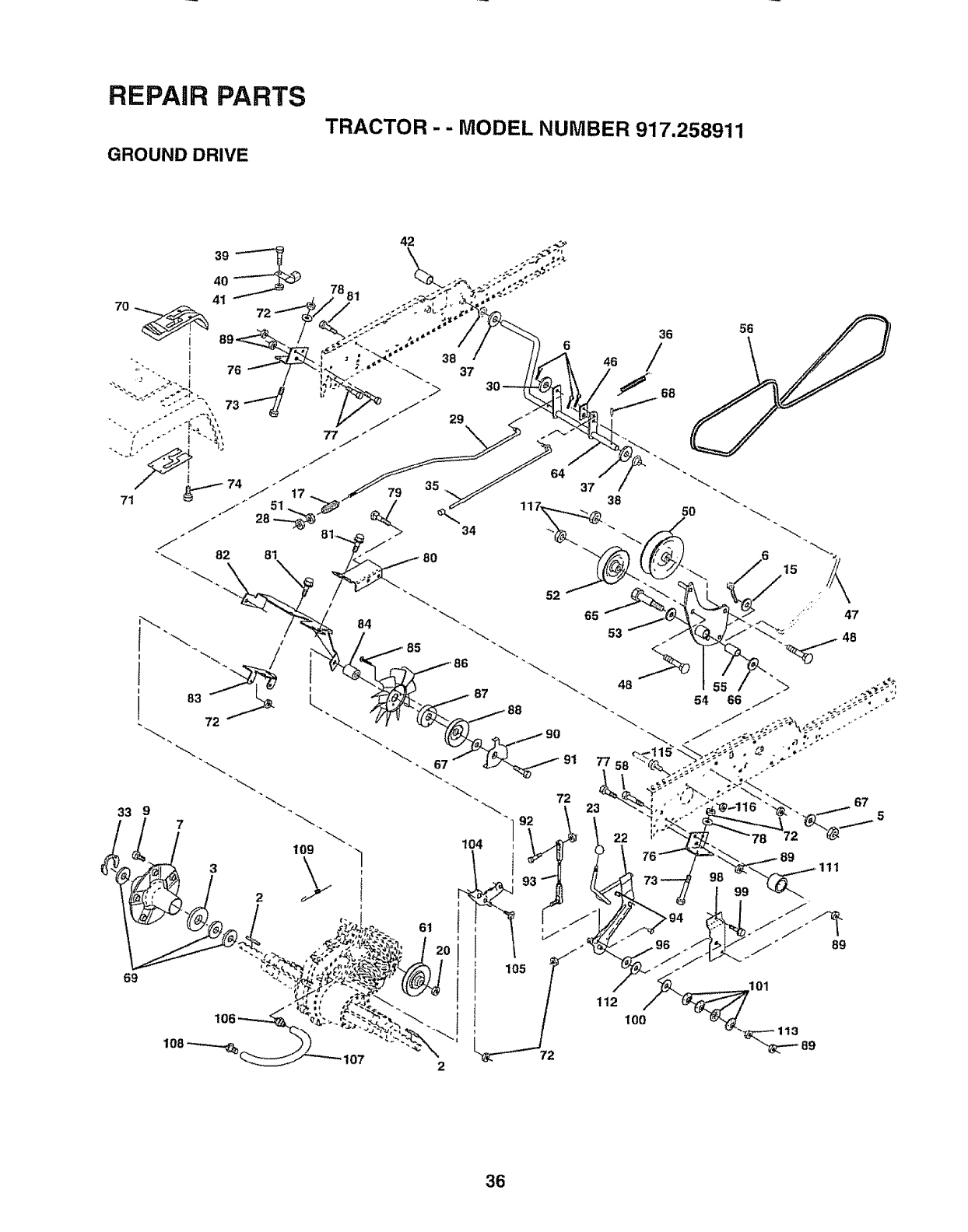
"_O0_L NUMe_ 977"2S89!1
\
\
/
2
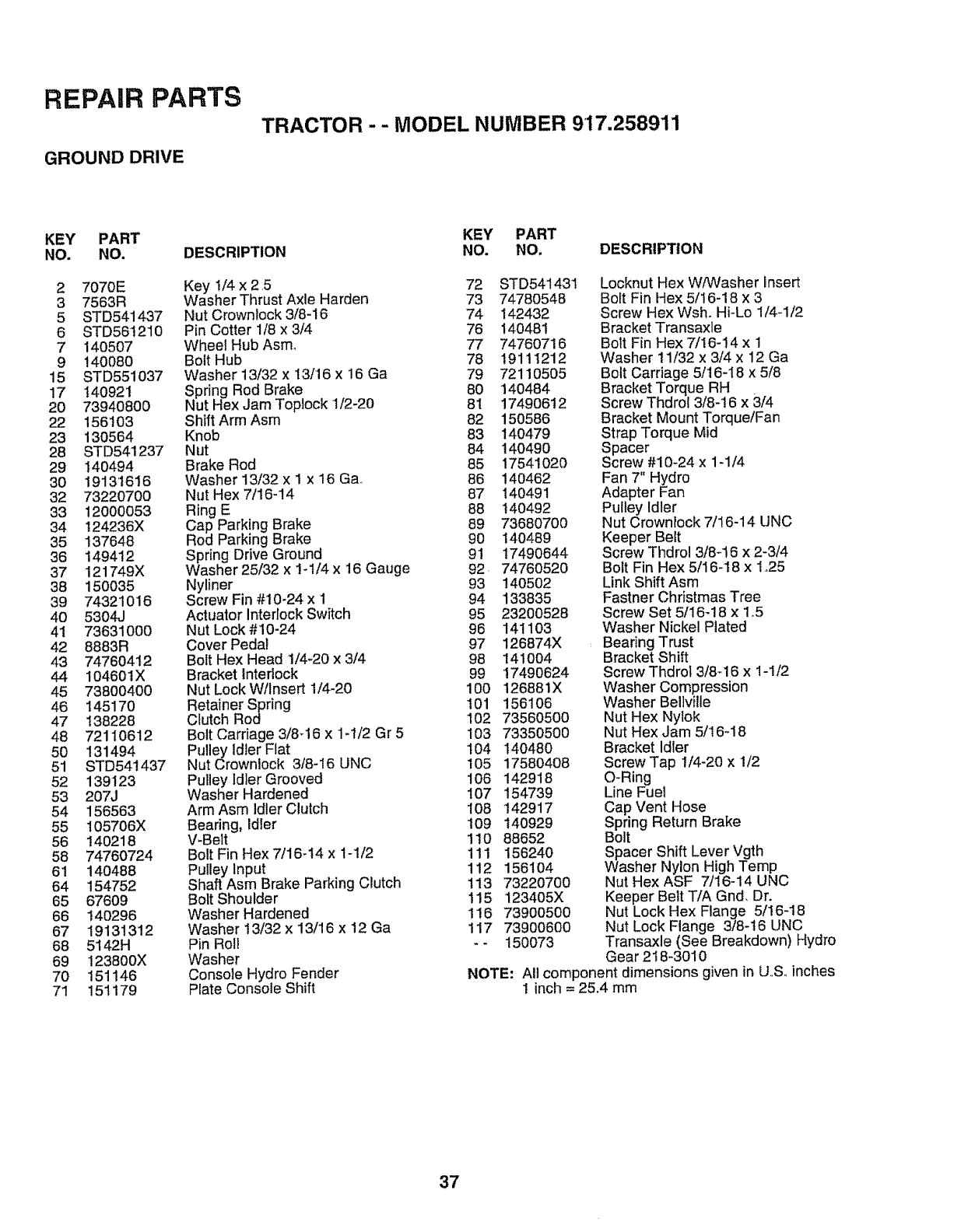
REPAIR PARTS
GROUND DRIVE
TRACTOR - - MODEL NUMBER 9'17.258911
KEY PART
NO. NO.
2 7070E
3 7563R
5 STD541_37
6 STD56t210
7 140507
9 140080
15 STD551037
17 140921
20 73940800
22 156103
23 130564
28 STD541237
29 140494
30 19131616
32 73220700
33 12000053
34 124236X
35 137648
36 149412
37 121749X
38 150035
39 74321016
40 5304J
41 73631000
42 8883R
43 7476O412
44 104601X
45 73800400
46 145170
47 138228
48 72110612
50 131494
51 STD541437
52 139123
53 207J
54 156563
55 105706X
56 140218
58 7476O724
61 140488
64 154752
65 67609
66 140296
67 19131312
68 5142H
69 123800X
70 151146
71 151179
DESCRIPTION
Key 1/4 x 2,5
Washer Thrust Axle Harden
Nut Crownlock 3/8-16
Pin Cotter 1/8 x 3/4
Wheel Hub Asmo
Bolt Hub
Washer 13/32 x 13/16 x 16 Ga
Spring Rod Brake
Nut Hex Jam Toplock 1/2-20
Shift Arm Asm
Knob
Nut
Brake Rod
Washer 13/32 x I x 16 Gao
Nut Hex 7/16-14
Ring E
Cap Parking Brake
Rod Parking Brake
Spring Drive Ground
Washer 25/32 x 1-!/4 x 16 Gauge
Nyliner
Screw Fin #10-24 x 1
Actuator interlock Switch
Nut Lock #10-24
Cover Pedal
Bolt Hex Head 1/4-20 x 3/4
Bracket Interlock
Nut Lock W/Insert i/4-20
Retainer Spring
Clutch Rod
Bolt Carriage 3/8_16 x 1-1/2 Gr 5
Pulley Idler Flat
Nut Crownlock 3/8-I6 UNC
Pulley Idler Grooved
Washer Hardened
Arm Asm Idler Clutch
Bearing, Idler
V-Belt
Bolt Fin Hex 7/16-14 x 1-1/2
Pulley Input
Shaft Asm Brake Parking Clutch
Bolt Shoulder
Washer Hardened
Washer ! 3/32 x 13/16 x 12 Ga
Pin Roll
Washer
Console Hydro Fender
Plate Console Shift
KEY PART
NO. NO. DESCRIPTION
72 STD541431
73 74780548
74 142432
76 140481
77 74760716
78 19111212
79 72110505
80 140484
81 17490612
82 150586
83 140479
84 140490
85 17541020
86 140462
87 140491
88 140492
89 73680700
90 140489
9! 17490644
92 74760520
93 140502
94 133835
95 23200528
96 141103
97 126874X
98 141004
99 '17490624
100 126881X
101 1561O6
102 73560500
103 73350500
104 140480
105 17580408
106 142918
107 154739
I08 142917
t09 140929
110 88652
111 156240
112 156104
113 7322O700
115 123405X
116 7390O500
117 73900600
-- 150073
Locknut Hex W/Washer insert
Boft Fin Hex 5/16-18 x 3
Screw Hex Wsho Hi-Lo 1/4-1/2
Bracket Transaxle
Bolt Fin Hex 7/16-14 x 1
Washer 11/32 x 3/4 x 12 Ga
Bolt Carriage 5/16-18 x 5/8
Bracket Torque RH
Screw Thdrol 3/8-16 x 3/4
Bracket Mount Torque/Fan
Strap Torque Mid
Spacer
Screw #10-24 x 1-1/4
Fan 7" Hydro
Adapter Fan
Pulley Idler
Nut Crowniock 7/16-14 UNC
Keeper Belt
Screw Thdrol 3/8-16 x 2-3/4
Bolt Fin Hex 5/16-18 x 1,,25
Link Shift Asm
Fastner Christmas Tree
Screw Set 5/I6-18 x 1o5
Washer Nickel Plated
Bearing Trust
Bracket Shift
Screw Thdrol 3/8-16 x I-1/2
Washer Compression
Washer Bellvitle
Nut Hex Nylok
Nut Hex Jam 5/! 6-18
Bracket Idler
Screw Tap i/4-20 x 1/2
O-Ring
Line Fuel
Cap Vent Hose
Spdng Return Brake
Bolt
Spacer Shift Lever Vgth
Washer Nylon High Temp
Nut Hex ASF 7/16-14 UNC
Keeper Belt T/A Gnd, Dr.
Nut Lock Hex Flange 5/16-18
Nut Lock Flange 3/8-16 UNC
Transaxle (See Breakdown) Hydro
Gear 218-3010
NOTE: All component dimensions given in U.,Soinches
1 inch = 25.4 mm
37
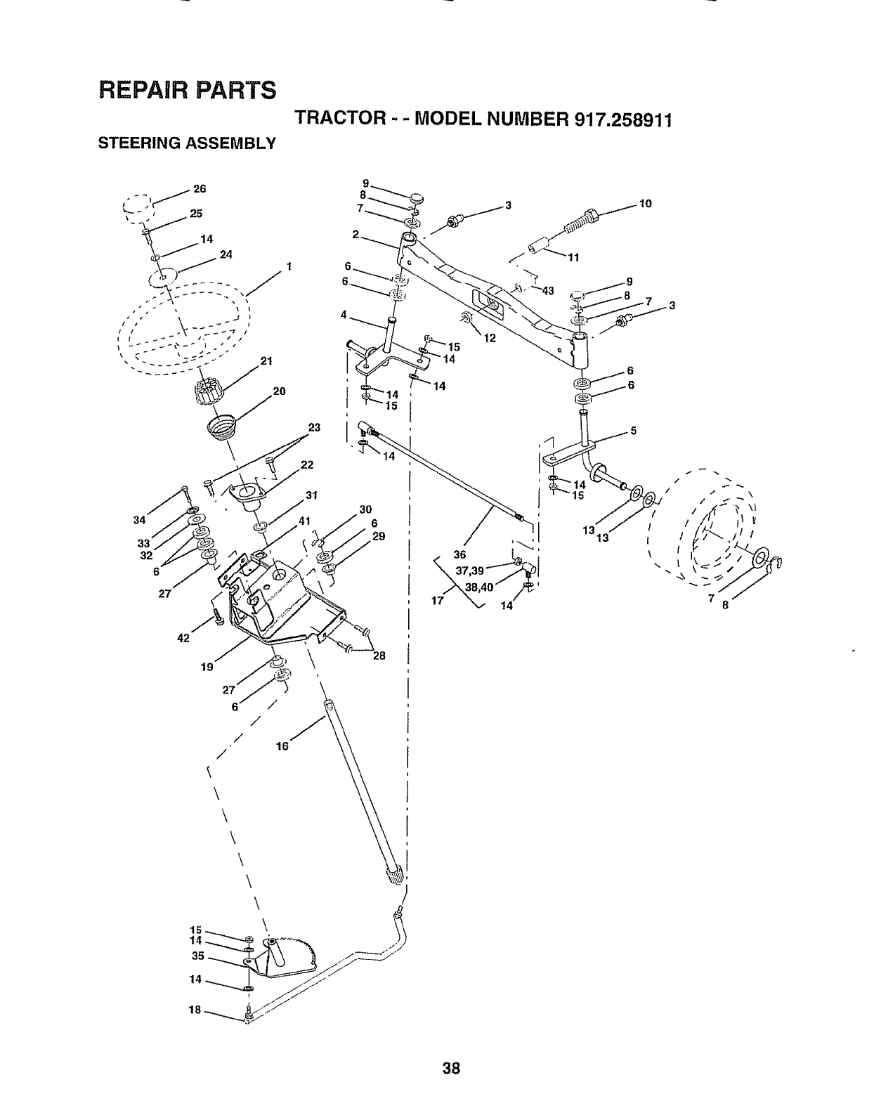
REPAIR PARTS
STEERING ASSEMBLY
TRACTOR - - MODEL NUMBER 917.258911
\
34
33"
19
6/
/
/"
\
\
\
\
,\
\
21
20
/
16
23
38
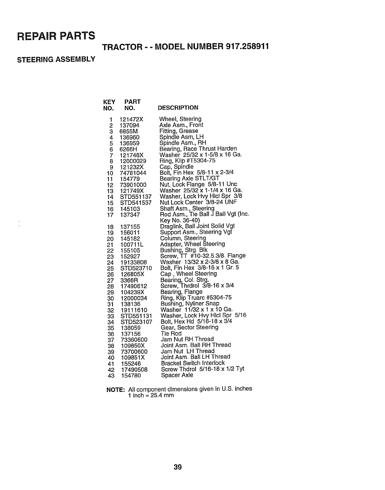
REPAIR PARTS
STEERING ASSEMBLY
TRACTOR --MODEL NUMBER 917.258911
KEY PART
NO. NO. DESCRIPTION
1 121472X
2 137094
3 6855M
4 136960
5 136959
6 6266H
7 121748X
8 12000029
9 121232X
10 74781044
11 154779
12 73901000
13 !21749X
14 STD551t37
I5 STD541537
16 145103
17 137347
18 137155
19 156011
20 145182
21 100711L
22 155105
23 152927
24 19133808
25 STD523710
26 126805X
27 3366R
28 17490612
29 104239X
30 12000034
3! 138136
32 19111610
33 STD551131
34 STD523107
35 138059
36 137156
37 73360600
38 109850X
39 73700600
40 109851X
4'1 155246
42 17490508
43 154780
Wheel, Steering
Axle Asm,, Front
Fitting, Grease
Spindle Asm, LH
Spindle Asm.., RH
Bearing, Race Thrust Harden
Washer 25/32 x 1-5/8 x 16 Ga..
Ring, Ktip #T5304-75
Cap, Spindie
Bolt, Fin Hex 5/8-11 x 2-3/4
Bearing Axle STLT/GT
Nut, Lock Flange 5/8-11 Unc
Washer 25/32 x 14/4 x 16 Ga.
Washer, Lock Hvy Hlcl Spr 3/8
Nut Lock Center 3/8-24 UNF
Shaft Asm., Steering
Rod Asm., Tie Bail J Bail Vgt (Inco
Key No. 36-40)
Drag_ink, Ball Joint Solid Vgt
Support Asmo, Steering Vgt
Column, Steering
Adapter, Wheel Steering
Bushing, Strg. BIk
Screw, TT #10-32.5.3/& Flange
Washer 13/32 x 2-3/8 x 8 Gao
Bolt, Fin Hex 3/8-16 x I Gr..5
Cap, Wheel Steering
Bearing, CoL Strg.
Screw, Thrdrol 3/8-16 x 3/4
Bearing, Flange
Ring, Klip Truarc #5304-75
Bushing, Nyliner Snap
Washer 11/32 x I x 10 Ga.
Washer, Lock Hvy HIc_Spr 5/16
Bolt, Hex Hd 5/16-! 8 x 3/4
Gear, Sector Steering
Tie Rod
,Jam Nut RH Thread
Joint Asm. Ball RH Thread
Jam Nut LH Thread
Joint Asm. Ball LH Thread
Bracket Switch Interlock
Screw Thdrol 5/16-18 x !/2 Tyt
Spacer Axle
NOTE: All component dimensions given in UoS.inches
1inch = 25°4 mm
39
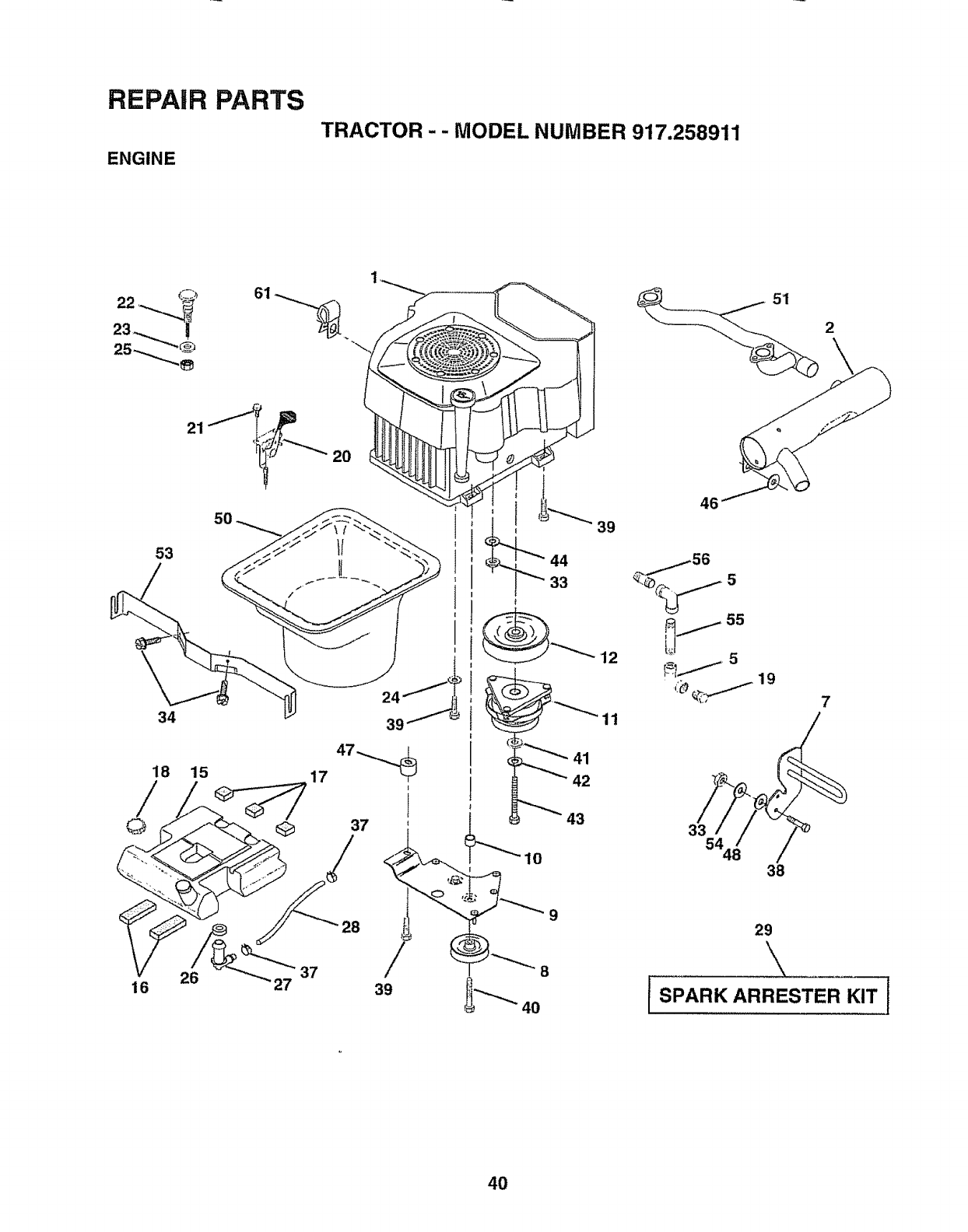
REPAIR PARTS
ENGINE
TRACTOR -- MODEL NUMBER 917.258911
53
34
18 15 17
16 26 27 37
2O
44
39
I
1
37
28
t
"8
39 10
41
42
43
39
12
11
46
/55
,:_%_._ 19 7
3354
38
29
\
4O
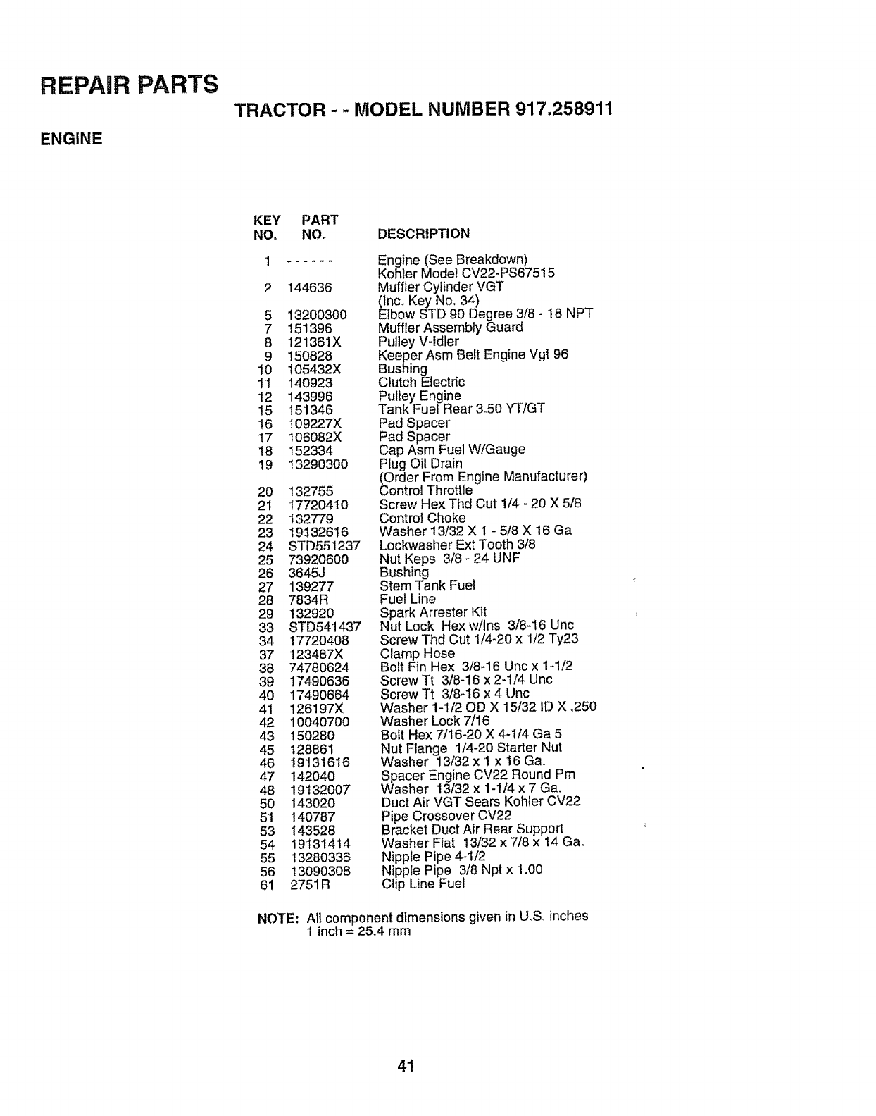
REPAIR PARTS
ENGINE
TRACTOR - - MODEL NUMBER 917.258911
KEY PART
NO. NO_ DESCRIPTION
144636
5 13200300
7151396
8 121361X
9150828
10 105432X
11 140923
12 143996
15 151346
16 109227X
17 106082X
18 152334
19 13290300
2O 132755
21 17720410
22 132779
23 19532616
24 STD551237
25 73920600
26 3645J
27 139277
28 7834R
29 132920
33 STD54i437
34 1772O408
37 123487)(
38 74780624
39 17490636
4O 17490664
4i i26197X
42 10040700
43 150280
45 128861
46 19131616
47 142040
48 19132007
50 143020
51 140787
53 143528
54 19131414
55 13280336
56 13090308
61 2751R
Engine (See Breakdown)
Kohler Model CV22-PS67515
Muffler Cylinder VGT
(Inc,, Key No. 34)
Elbow STD 90 Degree 3/8 - 18 NPT
Muffler Assembly Guard
Pulley V-Idler
Keeper Asm Belt Engine Vgt 96
Bushing
Clutch Electric
Pulley Engine
Tank FueJ Rear 350 YT/GT
Pad Spacer
Pad Spacer
Cap Asm Fuel W/Gauge
Plug Oil Drain
(Order From Engine Manufacturer)
Control Throttle
Screw Hex Thd Cut 1/4 - 20 X 5/8
Control Choke
Washer 13/32 X 1 - 5/8 X 16 Ga
Lockwasher Ext Tooth 3/8
Nut Keps 3/8 - 24 UNF
Bushing
Stem Tank Fuel
Fuel Line
Spark Arrester Kit
Nut Lock Hexw/Ins 3/8-16 Unc
Screw Thd Cut 1/4-20 x 1/2 Ty23
Clamp Hose
Bolt Fin Hex 3/8-16 Unc x 1-1/2
Screw Tt 3/8-16 x 2-1/4 Unc
Screw Tt 3/8-16 x 4 Unc
Washer 1-1/20D X 15/32 ID X ,250
Washer Lock 7/t6
Bolt Hex 7/16-20 X 4-1/4 Ga 5
Nut Flange 1/4-20 Starter Nut
Washer 13/32 x t x 16 Ga.
Spacer Engine CV22 Round Pm
Washer 13/32 x 1-1/4 x 7 Ga.
Duct Air VGT Sears Kohler CV22
Pipe Crossover CV22
Bracket Duct Air Rear Support
Washer Flat 13/32 x 7/8 x 14 Ga.
Nipple Pipe 4-1/2
Nipple Pipe 3/8 Npt x 1.00
Chp Line Fuel
NOTE: At1component dimensions given in U_S, inches
1 inch =25,4 mm
41
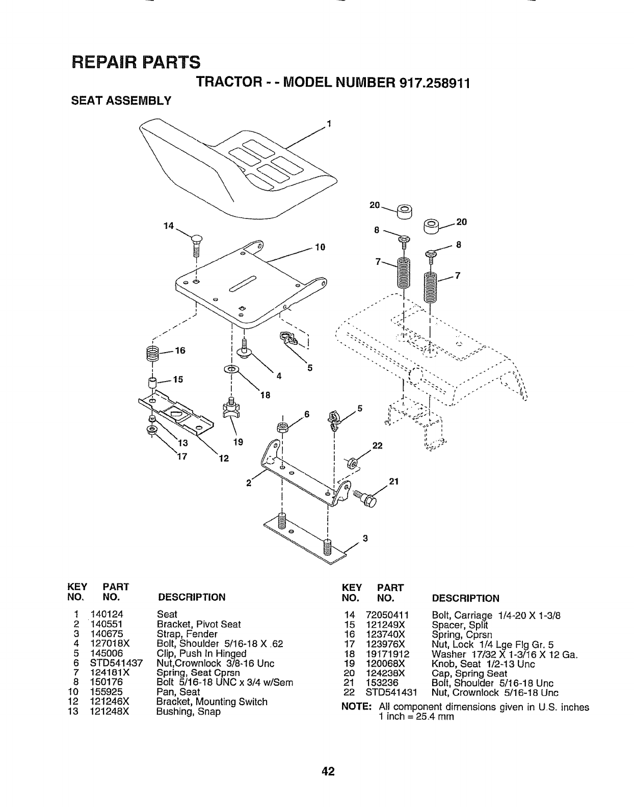
REPAIR PARTS
TRACTOR - - MODEL NUMBER 917.258911
SEAT ASSEMBLY
14
5
4
KEY PART
NO. NO.
1140124
2 140551
3 140675
4 127018X
5145006
6 STD541437
7 t24181X
8 150176
!0 155925
12 121246X
13 121248X
DESCRIPTION
Seat
Bracket, Pivot Seat
Strap, Fender
Bolt, Shoulder 5/16-18 X .62
Clip, Push In Hinged
Nut,Crowniock 3/8-16 Unc
Spring, Seat Cprsn
Bolt 5/16-18 UNC x 3/4 w/Sem
Pan, Seat
Bracket, Mounting Switch
Bushing, Snap
KEY PART
NO. NO, DESCRIPTION
14 72050411
15 121249X
16 123740X
17 123976X
18 19171912
19 120068X
20 124238X
21 153236
22 STD541431
Bolt, Carriage 1/4-20 X 1-3/8
Spacer', Split
Spring, Cprsn
Nut, Lock 1/4 Lge Fig Gr. 5
Washer t7/32 X 1-3/16 X 12 Ga.
Knob, Seat 1/2-13 Unc
Cap, Spring Seat
Bolt, Shoulder 5/16-18 Unc
Nut, C[ownlock 5/16-18 Unc
NOTE: All component dimensions given in U.S. inches
1 inch = 25.4 mm
42
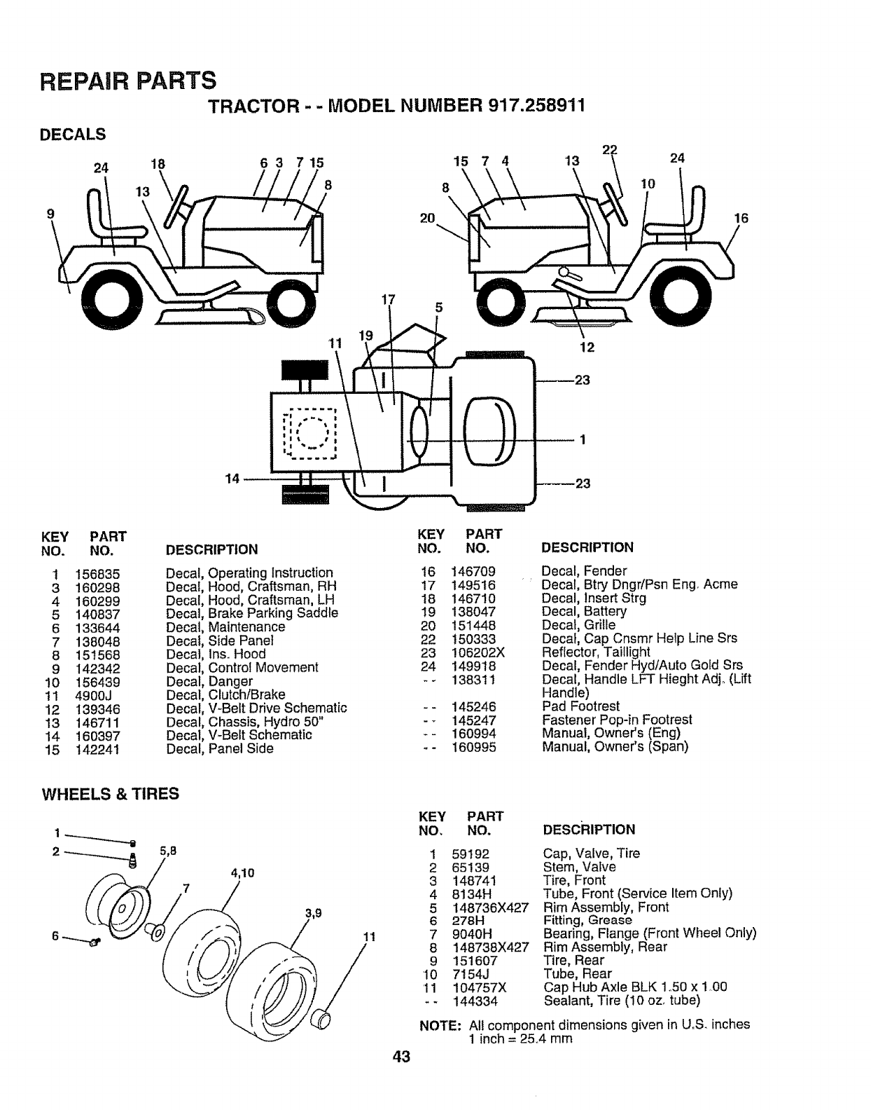
REPAIR
DECALS
24
9
PARTS
TRACTOR - - MODEL NUMBER 917.258911
18 6 3 715 15 7 4 "13
13 8 8
20
24
't0
16
15
!2
14
KEY PART
NO. NO.
1 156835
3 160298
4 160299
5 140837
6 133644
7 138048
8 151568
9 142342
!0 156439
tl 4900J
12 139346
!3 146711
14 160397
15 142241
DESCRIPTION
Decal,
Decal.
Decal.
Decal.
Decal
Decal
Decal
Decal
Decal
Decal
Decal
Decal
Decal
Decal
Operating Instruction
Hood, Craftsman, RH
Hood, Craftsman, LH
Brake Parking Saddle
Maintenance
Side Panel
Ins. Hood
Control Movement
Danger
Clutch/Brake
V-Belt Drive Schematic
Chassis, Hydro 50"
V_Belt Schematic
Panel Side
KEY
NO.
16
17
18
19
2O
22
23
24
PART
NO,
146709
149516
146710
138047
151448
150333
!06202X
149918
1383t1
145246
145247
160994
16O995
DESCRIPTION
Decal, Fender
Decal, Btry Dngr/Psn Eng. Acme
Decal, Insert Strg
Decal, Battery
Decal Grille
Decal Cap Cnsmr Help Line Srs
Reflector, Taillight
Decal Fender Hyd/Auto Gold Srs
Decal Handle LFT Hieght Adj. (Lift
Handle)
Pad Footrest
Fastener Pop-in Footrest
Manual, Owner's (Eng)
Manual, Owner's (Span)
WHEELS & TIRES
2_5,8 4,10
43
KEY PART
NO, NO. DEscRIPTION
1 59192
2 65139
3 148741
4 8134H
5 148736X427
6 278H
7 9040H
8 148738X427
9 151607
10 7154J
11 104757X
.- 144334
Cap, Valve, Tire
Stem, VaLve
Tire, Front
Tube, Front (Service Item Only)
Rim Assembly, Front
Fitting, Grease
Bearing, Flange (Front Wheel Only)
Rim Assembly, Rear
Tire, Rear
Tube, Rear
Cap Hub Axle BLK 1°50 x 1,00
Sealant, Tire (10 oz, tube)
NOTE: All component dimensions given in UoS. inches
1 inch = 25°4 mm
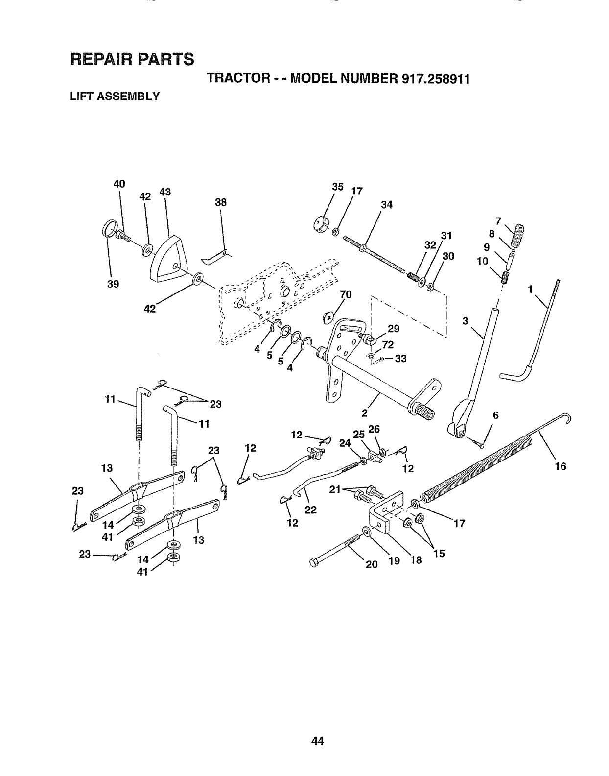
REPAIR PARTS
LIFT ASSEMBLY
TRACTOR - - MODEL NUMBER 917.258911
40
39
42 43
42
35 17
38
//
4
7O
4
2
34
29
72
33
12
15
2O 19 18
44
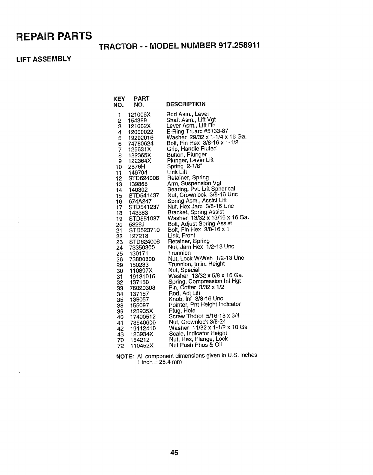
REPAIR PARTS
LIFT ASSEMBLY
TRACTOR - - MODEL NUMBER 917.2589'11
KEY PART
NO. NO. DESCRIPTION
1 121006X
2 154389
3 121002X
4 120O0022
5 19292016
6 74780624
7 125631X
8 122365X
9 122364X
10 2876H
11 146704
I2 STD624008
13 139868
14 140302
15 8TD54!437
16 674A247
17 8TD541237
18 143363
19 STD551037
20 5328J
21 STD523710
22 127218
23 8TD624008
24 73350800
25 130171
26 73800800
29 150233
30 1!0807X
31 19131016
32 137150
33 76020308
34 137167
35 138057
38 155097
39 123935X
40 17490512
41 73540600
42 19112410
43 123934X
70 154212
72 110452X
Rod Asm., Lever
Shaft Asm.., Lift Vgt
Lever Asm., Lift Rh
E-Ring Truarc #5133-87
Washer 29/32 x 1-1/4 x '16 Ga,
Bolt, Fin Hex 3/8-16 x 1-1/2
Grip, Handle Fluted
Button, Plunger
Plunger, Lever Lift
Spring 2-1/8"
Link Lift
Retainer, Spring
Arm, Suspension Vgt
Bearing, Pvt. Lift Spherical
Nut, Crownlock 3/8-16 Unc
Spring Asm., Assist Lift
Nut, Hex Jam 3/8-t6 Unc
Bracket, Spring Assist
Washer 13/32 x I3/t6 x 16 Gao
Bolt, Adjust Spring Assist
Bolt, Fin Hex 3/8-16 x 1
Link, Front
Retainer, Spring
Nut, Jam Hex 1/2-13 Unc
Trunnion
Nut, Lock WiWsh 1/2-13 Unc
Trunnion, lnfin. Height
Nut, Special
Washer 13/32 x 5/8 x 16 Ga.
Spring, Compression Inf Hgt
Pin, Cotter 3/32 x 1/2
Rod, Adj Lift
Knob, tnf 3/8-16 Unc
Pointer, Pnt Height indicator
Plug, Hole
Screw Thdrot 5/16-18 x 3/4
Nut, Crownlock 3/8-24
Washer t1132 x 1-1/2 x 10 Ga.
Scale, Indicator Height
Nut, Hex, Flange, Lock
Nut Push Phos & Oi!
NOTE: Al! component dimensions given in U.S. inches
1 inch = 25.4 mm
45
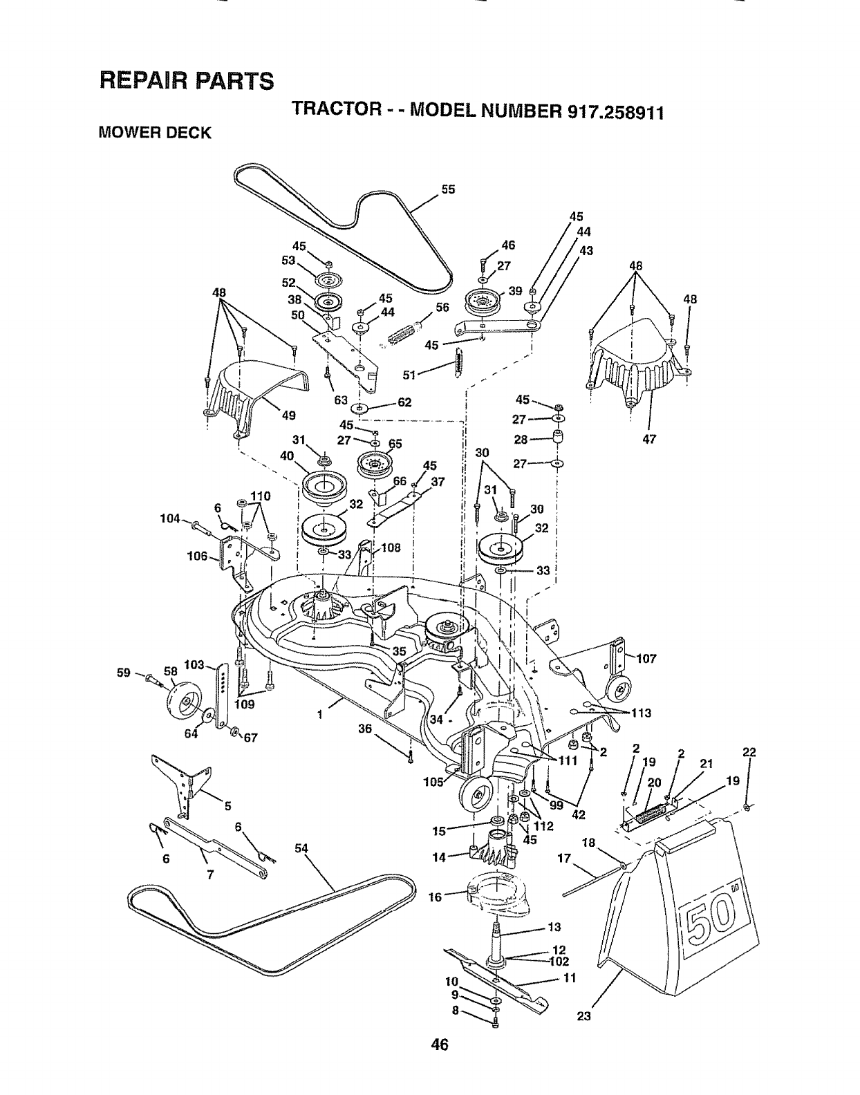
REPAIR PARTS
MOWER DECK
TRACTOR - - MODEL NUMBER 917.258911
48
55
45
48
48
221 22
11
46
23
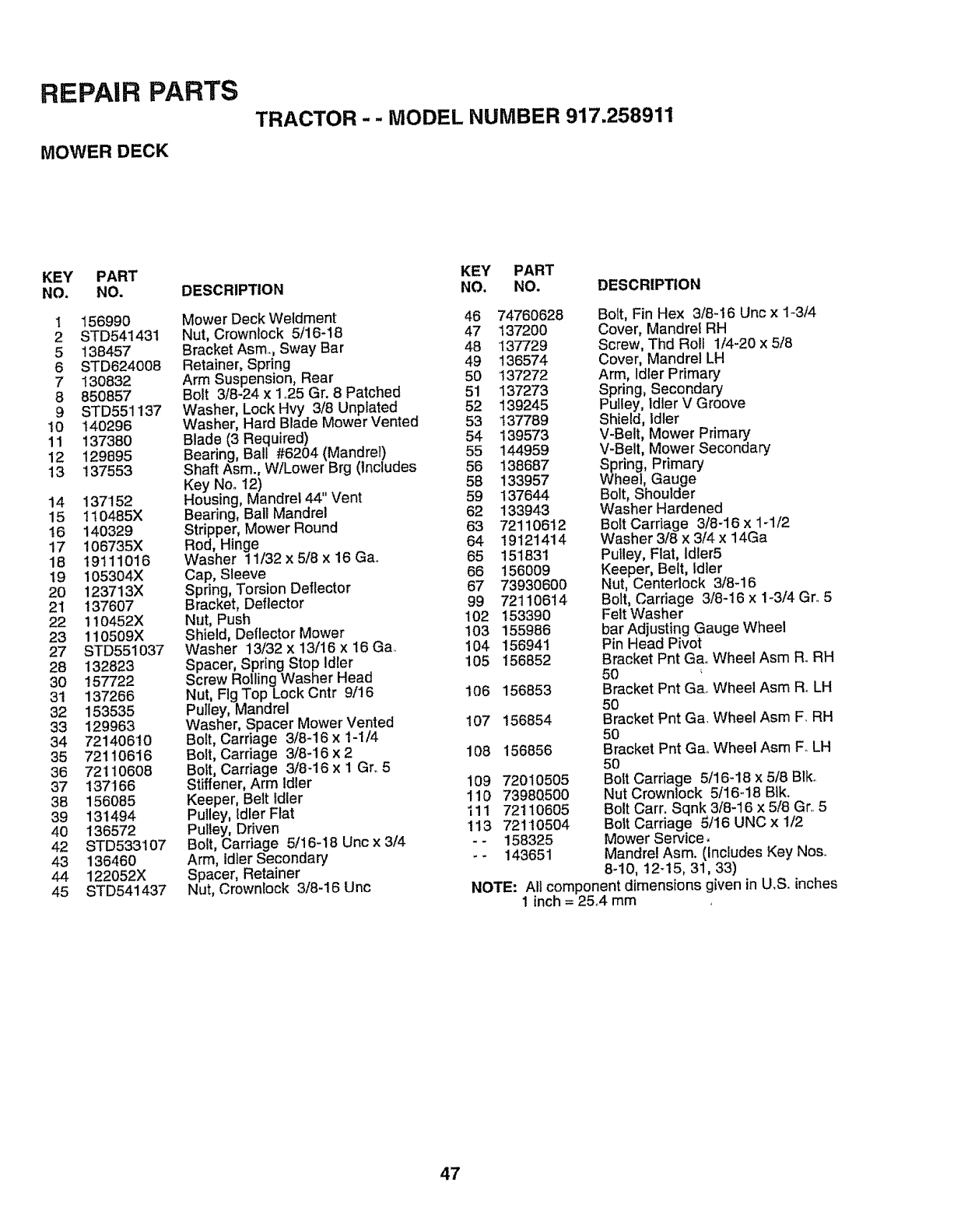
REPAIR PARTS
MOWER DECK
TRACTOR - - MODEL NUMBER 917.258911
KEY PART
NO. NO.
1 156990
2 STD541431
5 138457
6 STD624008
7 130832
8 850857
9 STD551137
10 140296
11 137380
12 129895
13 137553
14 137152
15 110485X
16 14O329
17 106735X
18 19111016
19 105304X
20 123713X
21 137607
22 1!0452X
23 110509X
27 STD551037
28 132823
30 157722
31 137266
32 153535
33 129963
34 721406t0
35 72110616
36 72110608
37 137166
38 156085
39 131494
40 136572
42 STD533107
43 136460
44 122052X
45 STD541437
DESCRIPTION
Mower Deck Weldment
Nut, Crownlock 5/16-18
Bracket Asm., Sway Bar
Retainer, Spring
Arm Suspension, Rear
Bolt 3/8-24 x 1°25 Gr. 8 Patched
Washer, Lock Hvy 3/8 Unpfated
Washer, Hard Blade Mower Vented
Blade (3 Required)
Bearing, Ball #6204 (Mandrel)
Shaft Asm., W/Lower Brg (Includes
Key Noo t2)
Housing, Mandrel 44" Vent
Bearing, Ball Mandrel
Stripper, Mower Round
Rod, Hinge
Washer 11/32 x 5/8 x 16 Gao
Cap, Sleeve
Spring, Torsion Deflector
Bracket, Deflector
Nut, Push
Shield, Deflector Mower
Washer 13/32 x 13/16 x 16 Ga.
Spacer, Spring Stop idler
Screw RotlingWasher Head
Nut, Fig TopLock Cntr 9/16
Pulley, Mandrel
Washer, Spacer Mower Vented
Bolt, Carriage 3/8-16 x t-1/4
Bolt, Carriage 3/8-16 x 2
Bolt, Carriage 3/8-16 x 1 Gr,.5
Stiffener, Arm Idler
Keeper, Belt Idler
Pulley, Idler Flat
Pulley, Driven
Bolt, Carriage 5/16-18 Uric x 3/4
Arm, Idler Secondary
Spacer, Retainer
Nut, Crownlock 3/8-16 Unc
KEY PART
NO. NO. DESCRIPTION
46 74760628
47 137200
48 137729
49 136574
50 137272
51 137273
52 139245
53 137789
54 139573
55 144959
56 138687
58 133957
59 137644
62 133943
63 72110612
64 19121414
65 151831
66 156009
67 73930600
99 7211O614
102 153390
103 155986
104 156941
105 156852
106 156853
I07 156854
108 156856
109 72010505
110 7398Q500
111 72110605
!13 721t0504
-- 158325
-- 143651
Bolt, Fin Hex 3t8-16 Unc x 1-3/4
Cover, Mandrel RH
Screw, Thd Roll 1/4-20 x 5/8
Cover, Mandrel LH
Arm, Idler Primary
Spring, Secondary
Pulley, Idler V Groove
Shield, Idler
V-Belt, Mower Primary
V-Belt, Mower Secondary
Spring, Primary
Wheel, Gauge
Bolt, Shoulder
Washer Hardened
Bolt Carriage 3/8-16 x 1-1/2
Washer 3/8 x 3/4 x 14Ga
Pulley, Flat, Idler5
Keeper, Belt, Idler
Nut, Centerlock 3/8-16
Bolt, Carriage 3/8-16 x 1-3/4 Gr..5
Felt Washer
bar Adjusting Gauge Wheel
Pin Head Pivot
Bracket Pnt Gao Wheel Asm RoRH
50
Bracket Pnt GaoWheel Asm RoLH
5O
Bracket Pnt Ga. Wheel Asm F, RH
50
Bracket Pnt GaoWheel Asm F. LH
5O
Bolt Carriage 5/16-18 x 5/8 Blko
Nut Crown!ock 5/16_18 BIk.
Bolt Carr. Sqnk 3/8-16 x 5/8 Gr,.5
Bolt Carriage 5/16 UNC x 1/2
Mower Service,
Mandrel Asm. (Includes Key No&
8-10, 12-15, 31, 33)
NOTE: All component dimensions given in U,& inches
I inch = 25..4 mm
47
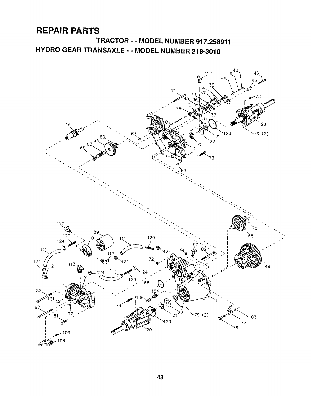
REPAIR PARTS
TRACTOR - -MODEL NUMBER 917,258911
HYDRO GEAR TRANSAXLE . . MODEL NUMBER 218.3010
7t
48
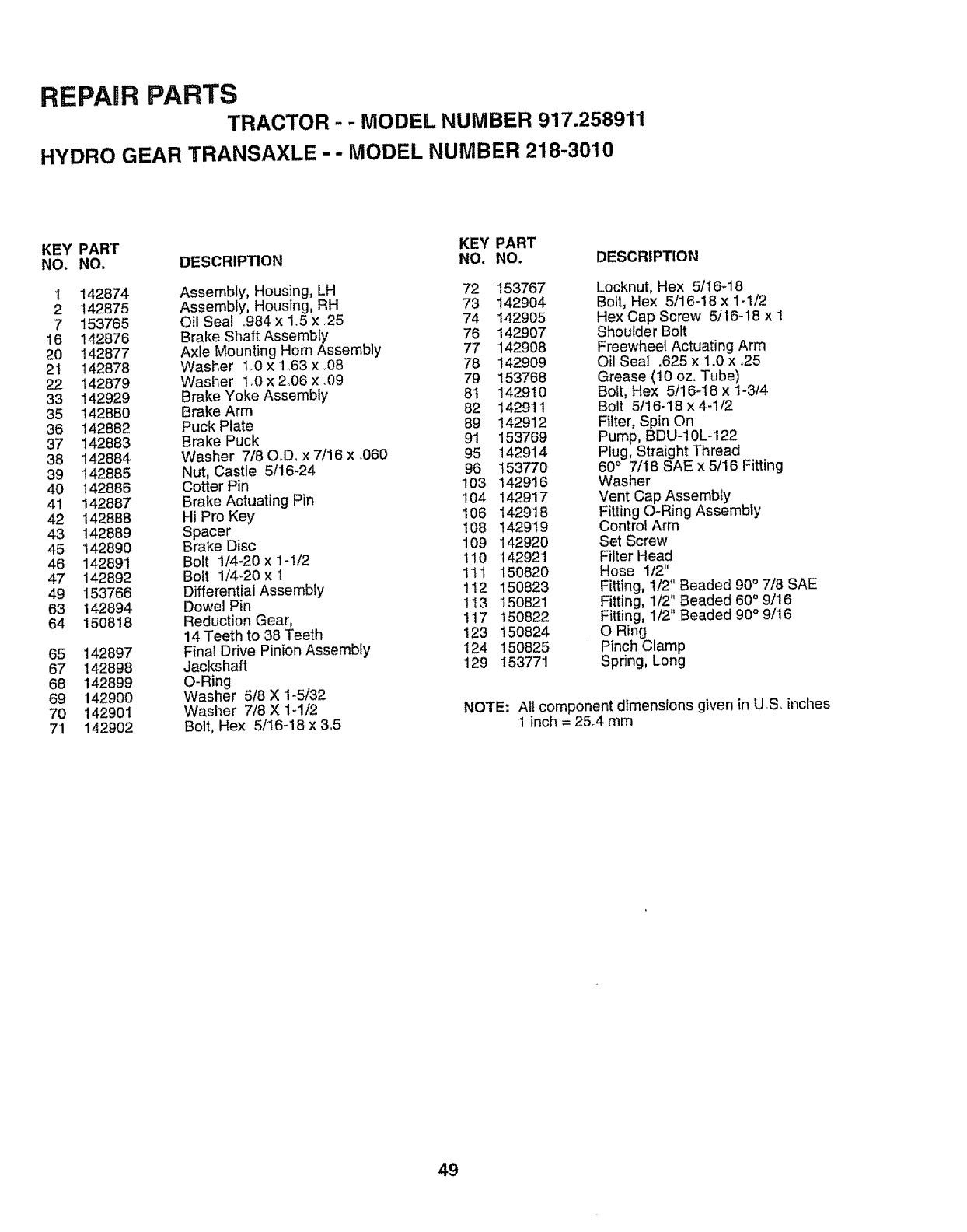
REPAIR PARTS
TRACTOR - - MODEL NUMBER 917.258911
HYDRO GEAR TRANSAXLE -- MODEL NUMBER 218-3010
KEY PART KEY PART
NO. NO. DESCRIP_ON NO. NO.
1 142874 Assembly, Housing, LH 72 153767
2 142875 Assembly, Housing, RH 73 142904
7 153765 Oi! Seal .984 x 1..5x.25 74 142905
16 142876 Brake Shaft Assembly 76 142907
20 142877 Axle Mounting Horn Assembly 77 t42908
21 142878 Washer 1o0x 1_63x.08 78 142909
22 t42879 Washer 1o0x 2°06 x .09 79 153768
33 142929 Brake Yoke Assembly 81 142910
35 142880 Brake Arm 82 t42911
36 142882 Puck Plate 89 142912
37 142883 Brake Puck 91 153769
38 142884 Washer 7/80.Do x 7/16 x ..060 95 142914
39 142885 Nut, Castle 5/16-24 96 153770
40 142886 Cotter Pin 103 142916
41 142887 Brake Actuating Pin 104 142917
42 142888 Hi Pro Key 106 142918
4.3 142889 Spacer 108 142919
45 142890 Brake Disc 109 142920
46 142891 Bolt 1/4-20x 1-1/2 110 142921
47 142892 Bolt 1/4_20x 1 111 150820
49 153766 Differential Assembly 112 150823
63 142894 Dowel Pin 113 150821
64 150818 Reduction Gear, 117 150822
14 Teeth to 38 Teeth 123 150824
65 142897 Final Drive Pinion Assembly 124 150825
67 142898 Jackshaft 129 153771
68 142899 O-Ring
69 142900 Washer 5/8 X 1-5/32
70 142901 Washer 7/8 X 1-1/2
71 142902 Bolt, Hex 5/16-16 x 3.5
DESCRIPTION
Locknut, Hex 5/16-18
Bolt, Hex 5/16-18 x 1-1/2
Hex Cap Screw 5/16-18 x 1
Shoulder Bolt
Freewheel Actuating Arm
Oil Seal .625 x 1.0 x .25
Grease (10 oz. Tube)
Bolt, Hex 5/16-18 x 1-3/4
Bolt 5/16_18 x 4-1/2
Filter, Spin On
Pump, BDU-10L-122
Plug, Straight Thread
60°7/18 SAE x 5/16 Fitting
Washer
Vent Cap Assembly
Fitting O-Ring Assembly
Control Arm
Set Screw
Filter Head
Hose 1/2"
Fitting, 1/2" Beaded 90°7/8 SAE
Fitting, 1/2" Beaded 60°9/16
Fitting, 1/2" Beaded 90" 9/16
O Ring
Pinch Clamp
Spring, Long
NOTE: All component dimensions given in U.Soinches
1 inch = 25.4 mm
49
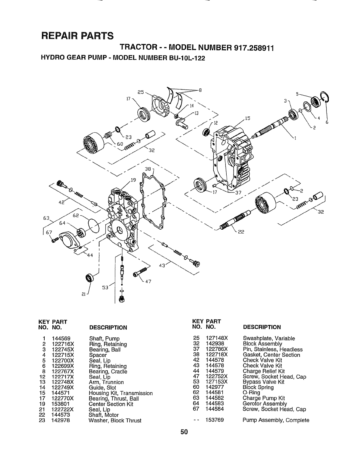
REPAIR PARTS
TRACTOR - -MODEL NUMBER 917.258911
HYDRO GEAR PUMP - MODEL NUMBER BU-10L-122
17
KEY
NO.
1
2
3
4
5
6
8
12
13
14
t5
17
19
21
22
23
PART
NO.
144569
122716X
122745X
122715X
122700X
122699X
122767X
122717X
122748X
122749X
144571
122770X
153801
122722X
144573
142978
DESCRIPTION
Shaft, Pump
Ring, Retaining
Bearing, Bait
Spacer
Seal, Lip
Ring, Retaining
Bearing, Cradle
Seal, Lip
Arm, Trunnion
Guide, Slot
Housing Kit, Transmission
Bearing, Thrust, Ball
Center Section Kit
Seal, Lip
Shaft, Motor
Washer, Block Thrust
50
KEY PART
NO, NO.
25 127148X
32 142938
37 122786X
38 122718X
42 144578
43 144578
44 144579
47 122752X
53 127153X
60 142977
62 144581
63 144582
64 144583
67 144584
153769
DESCRIPTION
Swashplate, Variable
Block Assembly
Pin, Stainless, Headless
Gasket, Center Section
Check Valve Kit
Check Valve Kit
Charge Relief Kit
Screw, Socket Head, Cap
Bypass Valve Kit
Block Spring
O-Ring
Charge Pump Kit
Gerotor Assembly
Screw, Socket Head, Cap
Pump Assembly, Complete
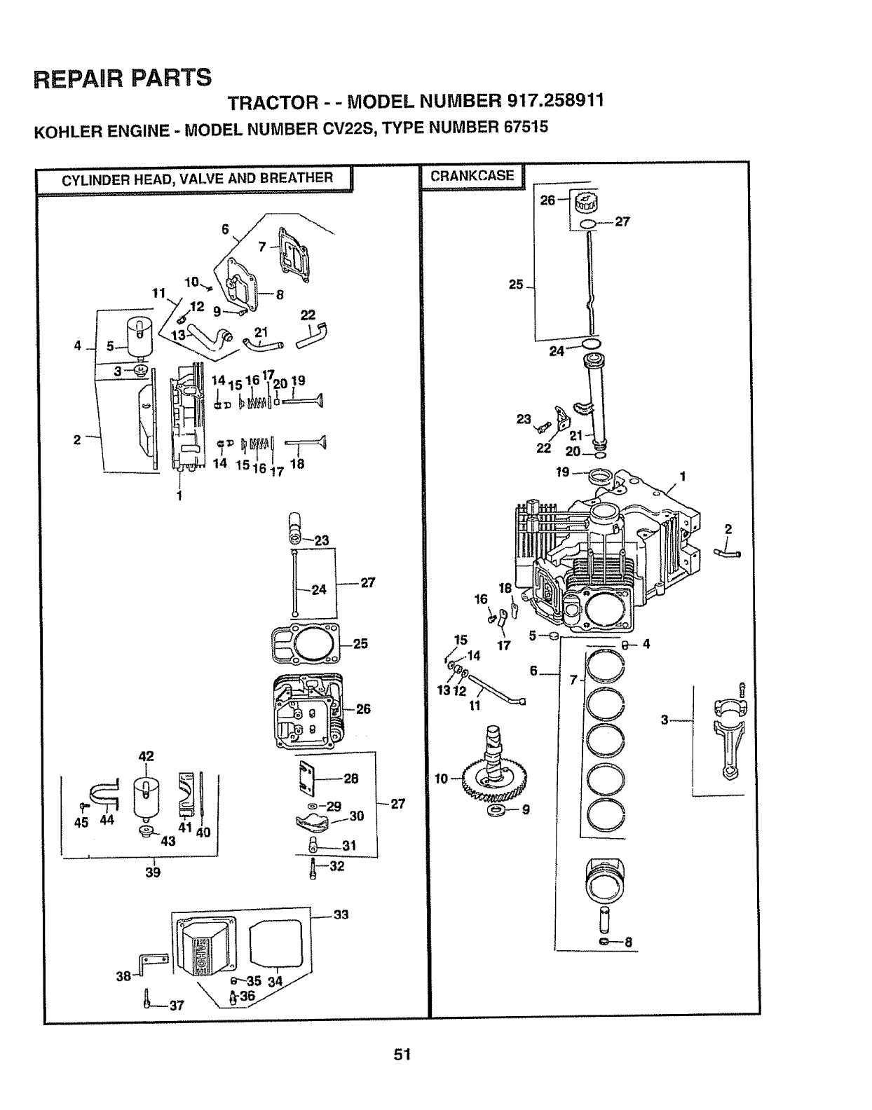
REPAIR PARTS
TRACTOR - - MODEL NUMBER 917.258911
KOHLER ENGINE -MODEL NUMBER CV22S, TYPE NUMBER 67515
42
39
_23
_27 ©
3_
2
t1!lj
51
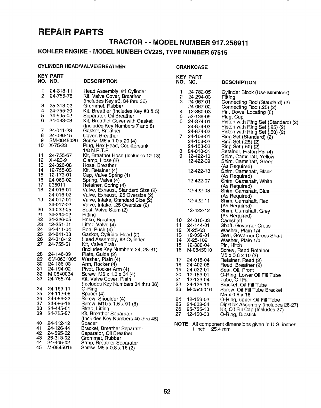
REPAIR PARTS
TRACTOR --MODEL NUMBER 917.258911
KOHLER ENGINE- MODEL NUMBER CV22S, TYPE NUMBER 67515
CYLINDER HEAD/V'ALVE/BREATHER CRANKCASE
KEY PART KEY PART
NO. NO. DESCRIPTION NO. NO. DESCRIPTION
1 24-318-11
2 24-755-76
3 25-313-02
4 24-755-20
5 24-595-02
6 24-033-03
7 24-04t-23
8 24-096-15
9 SM-0645020
10 X-75-23
11 24-755_67
12 X-426-9
13 24-326-O8
14 t2-755-03
15 !2-!73-01
16 24-089-02
t7 235011
18 24-016-01
24-0 t6-02
!9 24-017-01
24-017-02
2O 24-032-05
21 24-294-02
22 24-326-05
23 t2-351-0t
24 24-411-04
25 24-041-08
26 24-318-12
27 24-755-61
28 24-146-09
29 SM-0631005
30 24-186-03
31 24-194-02
32 M-0640034
33 24-755-74
34 24-153-11
35 24-112-08
36 24-086-32
37 24-086-16
38 24-445-01
39 24-755-57
Head Assembly, #1 Cylinder
Kit, Valve Cover, Breather
(Includes Key #3, 34 thru 36)
Grommet, Rubber
Kit, Breather (includes Key #3 & 5)
Separator, Oil Breather
Kit, Breather Cover' with Gasket
(Includes Key Numbers 7 and 8)
Gasket, Breather
Cover, Breather
Screw M6 x 1..0x 20 (4)
Plug, Hex Head, Countersunk
1/8 N.P_T..F.
Kit, Breather Hose (Includes 12-13)
Clamp, Hose (2)
Hose, Breather
Kit, Retainer (4)
Cap, Valve Spring (4)
Spring, Valve (4)
Retainer', Spring (4)
Valve, Exhaust, Standard Size (2)
Valve, Exhaust, °25 Oversize (2)
Valve, Intake, Standard Size (2)
Valve, Intake, _25Oversize (2)
Seat, Valve Stem (2)
Fitting
Hose, Breather
Lifter, Valve (4)
Rod, Push (4)
Gasket, Cylinder Head (2)
Head Assembly, #2 Cylinder
Kit, Valve Train
(Includes Key Numbers 24, 28-31)
Plate, Guide (2)
Washer, Plain (4)
Arm, Rocker (4)
Pivot, Rocker Arm (4)
Screw M6 x 1o0x 34 (4)
Kit, Valve Cover, Plain
(Includes Key Numbers 34 thru 36)
O-Ring
Spacer (4)
Screw, Shoulder (4)
Screw M10 x 1_5x 91 (8)
Strap, Lifting
Kit, Breather Separator
(Includes Key Numbers 40 thru 45)
Spacer
Bracket, Breather Separator
Separator, Oil Breather
Grommet, Rubber
Strap, Breather Separator
Screw M5 x 0..8x 16 (2)
4O 24-112-i2
41 24-126-44
42 24_595-02
43 25-313-02
44 24-445-02
45 M-0545016
1 24-782-05
2 24-294-03
3 24-067-01
24-067-02
4 !2-380-03
5 52-139-09
6 24-874-01
24-874-02
24-874-03
7 24-108-01
24-108-02
24-108-03
8 24-018-01
9 12-422-10
t2-422-09
12-422-13
12-422-07
12-422-08
12-422-11
12-422-12
10 24-010-03
11 24-144-01
12 X@5-63
13 12-032-01
14 X-25-102
15 12-380-04
16 M-0545010
17 24-018-04
18 24-402-05
19 24-032-01
20 12-153-01
21 12-123-04
22 24-126-19
23 M-0545016
24 12-153_02
25 24-038-04
26 25-755-13
27 12-153-03
NOTE:
Cylinder Block (Use Miniblock)
Fitting
Connecting Rod (Standard) (2)
Connecting Rod (_25) (2)
Pin, Dowel Locating (6)
Plug, Cup
Piston with Ring Set (Standard) (2)
Piston with Ring Set (.25) (2)
Piston with Ring Set (.50) (2)
Ring Set (Standard) (2)
Ring Set/:25/t2 /
Ring Set
Retainer, Piston Pin (4)
Shim, Camshaft, Yellow
Shim, Camshaft, Green
(As Required)
Shim, Camshaft, Black
(As Required)
Shim, Camshaft, White
(As Required)
Shim, Camshaft, Blue
(As Required)
Shim, Camshaft, Red
(As Required)
Shim, Camshaft, Grey
(As Required)
Camshaft
Shaft, Governor Cross
Washer, Plain 1/4
Seal, Governor Cross Shaft
Washer, Plain 1/4
Pin, Hitch
Screw, Reed Retainer
M5 x 0.8 x 10 (2)
Retainer', Reed }2)
Reed, Breather 2)
Seal, Oil, Front
O-Ring, Lower Oil Fill Tube
Tube, Oil Fill
Bracket, Oil Fill Tube
Screw, Oil Fill Tube Bracket
M5x0.8x 16
O-Ring, upper' Oil Fill Tube
Dipstick Assembly (includes 26-27)
Kit, Oil Fill Cap (Includes 27)
O-Ring, Dipstick
All component dimensions given in U..S.inches
t inch = 25..4 rnm
52
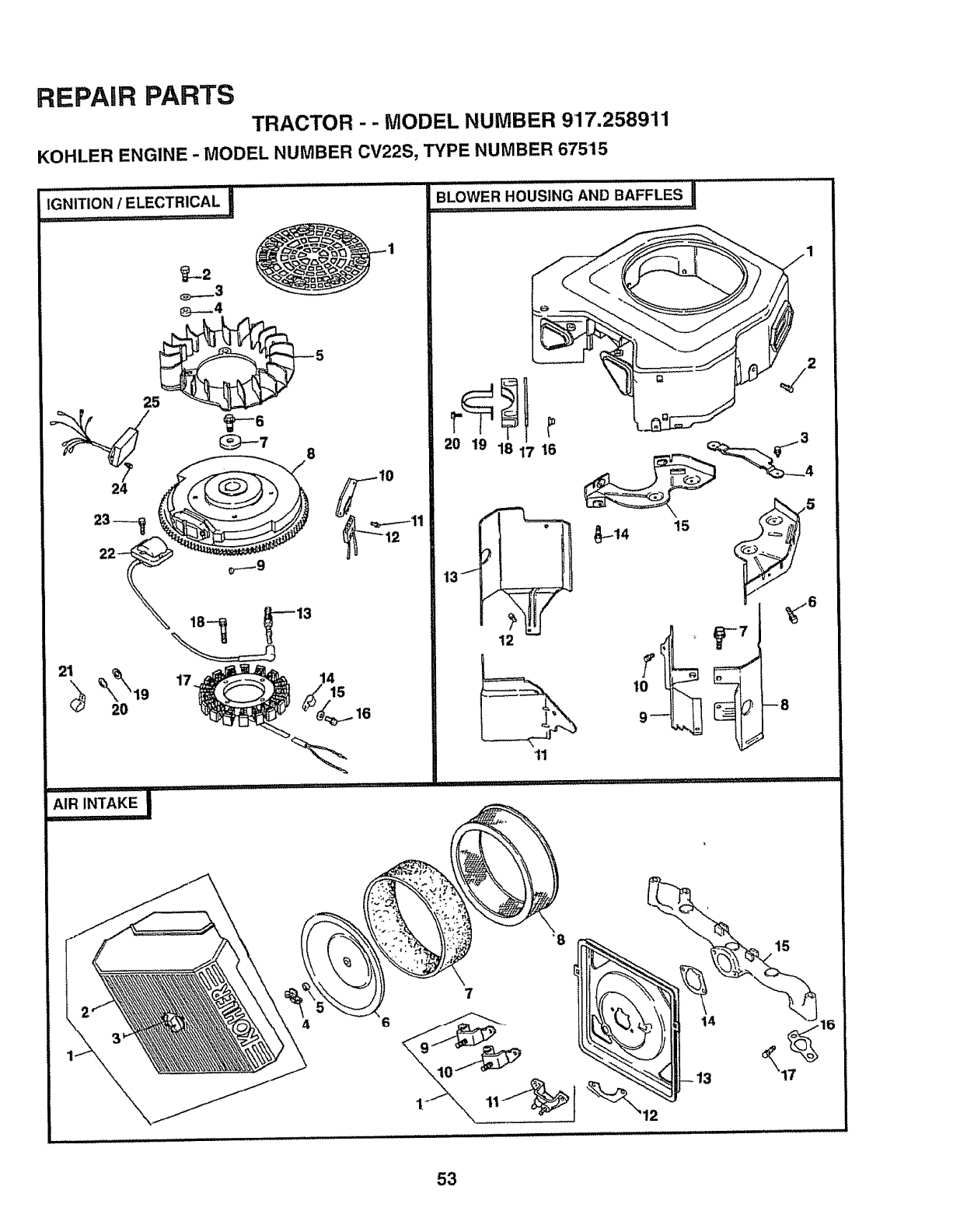
REPAIR PARTS
TRACTOR - - MODEL NUMBER 917.258911
KOHLER ENGINE - MODEL NUMBER CV22S, TYPE NUMBER 67515
10
17
_,.owE,,Ous,._,,oB_F_,._si.....................
20 19 18 17 16
12
'tl
1"
2
--8
4
7
15
53
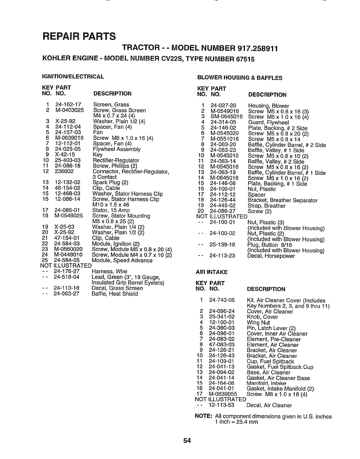
REPAIR PARTS
TRACTOR- - MODEL NUMBER 917.258911
KOHLER ENGINE -MODEL NUMBER CV22S, TYPE NUMBER 67515
IGNITION/ELECTRICAL BLOWER HOUSING & BAFFLES
KEY PART KEY PART
NO. NO. DESCRIPTION NO. NO. DESCRIPTION
1 24-t62-17
2 M-0403025
3 X-25-92
4 24-1t2-04
5 24-157-03
6 M-06390t6
7 12-t!2-01
8 24-025-05
9 X-42-15
10 25-403-03
11 24-086-18
12 236602
13 12-132-02
14 48-154-02
15 12-468-03
16 12-086-14
17 24-085-01
t8 M-0548025
Screen, Grass
Screw, Grass Screen
M4 x &7 x 24 (4)
Washer, Plain 1/2 (4)
Spacer, Fan (4)
Fan
Screw M6 x 1.0 x 16 (4)
Spacer, Fan (4)
Flywheel Assembly
Key
Rectifier-Regulator
Screw, Phillips (2)
Connector, Rectifier-Regulator,
3 Contact
Spark Plug (2)
Clip, Cable
Washer, Stator Harness Clip
Screw, Stator Harness Clip
MlOx 1.5 x 46
Stator, 15 Amp
Screw, Stator Mounting
M5 x 0_8x 25 (2)
Washer-, Plain 1/4 (2)
Washer, Plain 1/2 (2)
Clip, Cable
Module, Ignition (2)
Screw, Module M5 x 0.8 x 20 (4)
Screw, Module M4 x 0°7 x 10 (2)
Module, Speed Advance
ILLUSTRATED
24-176-27 Harness, Wire
-- 24-518-04 Lead, Green (3", 18 Gauge,
Insulated Grip Barrel Eyelets)
- - 24-113-18 Decal, Grass Screen
- 24-063-27 Baffle, Heat Shield
19 X-25-63
20 X-25-92
21 47-154-01
22 24-584-03
23 M-0560020
24 M-0448010
25 24-584-05
NOT
1 24-027-20 Housing, Blower
2 M-0549016 Screw M5 x 0.8 x 16 (37
3 SM-0645016 Screw M6xt..0x16(4 )
4 24-314-05 Guard, Flywheel
5 24-146=02 Plate, Backing, # 2 Side
6 M-0545020 Screw M5 x 0.8 x 20 (2)
7 M-0551016 Screw M5 x 0.8 x 14
8 24-063-20 Baffle, Cytinder Barrel, # 2 Side
9 24-063-23 Baffle, Valley, # 1 Side
10 M-0545010 Screw M5 x 0.8 x 10 (2)
11 24-063-14 Baffle, Valley, # 2 Side
12 M-0545016 Screw M5 x 0.8 x I6 (2)
13 24-063-19 Baffle, Cylinder Barrel, # 1 Side
14 M-0645016 Screw M6 x t.0 x 16 (2)
15 24-146-08 Plate, Backing, # 1 Side
16 24-100-01 Nut, Plastic
17 24-112-12 Spacer
18 24_126-44 Bracket, Breather Separator
19 24-445-02 Strap, Breather
20 24-086-27 Screw (2)
NOT ILLUSTRATED
-- 24-100-01 Nut, Ptastic (3)
(fncluded with Blower' Housing)
- - 24-100-02 Nut, Plastic (2)
(Included with Blower Housing)
-- 25-139-16 Plug, Button 9/16
(included with Blower Housing)
-- 24-113-23 Decal, Horsepower
AIR INTAKE
KEY PART
NO. NO. DESCRIPTION
24-743-05
2 24-096-24
3 25-341-02
4 12-t00-01
5 24-380-03
6 24-096-01
7 24-083-02
8 47-083-03
9 24_126-21
10 24-t26-43
11 24-109-01
12 24-041-13
13 24-094-02
14 24-041-14
15 24-164-06
t6 24-041-01
17 M-0639055
NOT
Kit, Air Cleaner Cover (Includes
Key Numbers 2, 3, and 9 thru 11)
Cover, Air Cleaner
Knob, Cover
Wing Nut
Pin, Latch Lever (2)
Cover, Inner Air Cleaner
Element, Pre-Cleaner
Element, Air Cleaner
Bracket, Air Cleaner
Bracket, Air Cleaner'
Cup, Fuel Spitback -.
Gasket, Fuel Spitback Cup
Base, Air' Cleaner
Gasket, Air Cleaner Base
Manffnfd, intake
Gasket, Intake Manifold (2)
Screw M6 x 1_0x t8 (4)
ILLUSTRATED
t2-113-53 Decal, Air' Cleaner
NOTE: All component dimensions given in U..S..inches
1 inch = 25.4 rnm
54
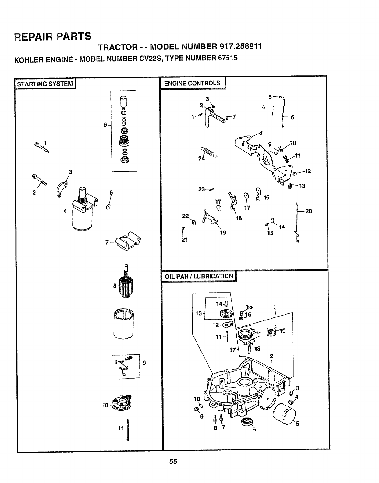
REPAIR PARTS
TRACTOR - - MODEL NUMBER 917.2589'11
KOHLER ENGINE -MODEL NUMBER CV22S, TYPE NUMBER 67515
S_A"RTING's",'_'_'EM!...........
iUlUl ul,ul.i
-
3
/
40
o
@
o
8.
22
T
21
3
23--,,"
19
5 -......_
o,j_o
),o
18
17
15
55
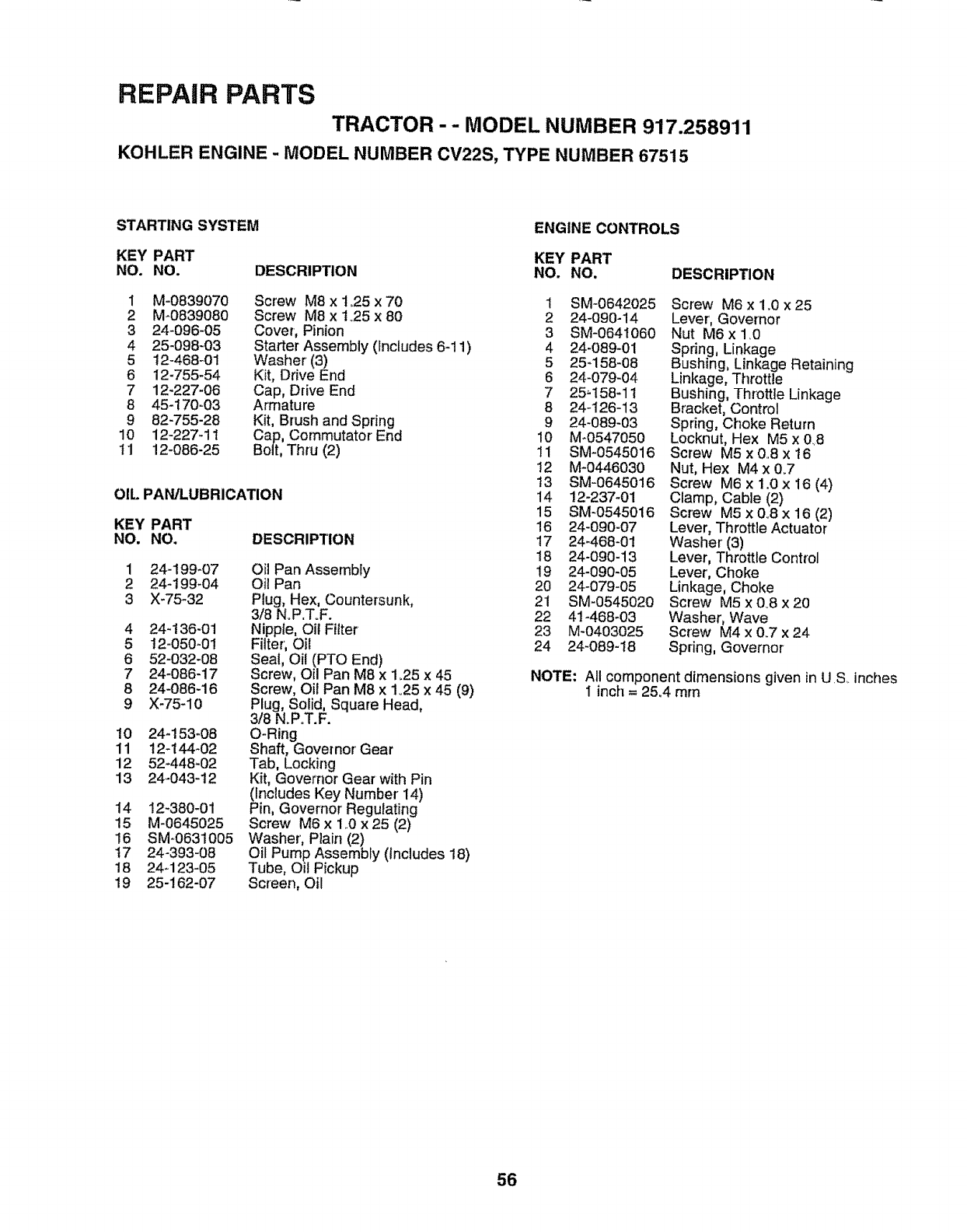
REPAIR PARTS
TRACTOR - - MODEL NUMBER 917.258911
KOHLER ENGINE -MODEL NUMBER CV22S, TYPE NUMBER 67515
STARTING SYSTEM ENGINE CONTROLS
KEY PART KEY PART
NO. NO. DESCRIP_ON NO. NO,
I M-0839070 Screw M8 x 1.25 x 70
2 M_0839080 Screw M8 x I_25 x 80
3 24-096-05 Cover, Pinion
4 25-098-03 Starter Assembly (Includes 6-11)
5 t2-468-01 Washer (3)
6 12-755-54 Kit, Drive End
7 12-227-06 Cap, Drive End
8 45-170-03 Armature
9 82-755-28 Kit, Brush and Spring
10 12-227-11 Cap, Commutator End
11 !2-086-25 Bolt, Thru (2)
OIL PAN/LUBRICATION
DESCRIPTION
KEY PART
NO. NO,
1 24-199-07
2 24-199-04
3 X-75-32
4 24-136-01
5 12-050-01
6 52-032-08
724-086-17
8 24-086-16
9 X-75-10
!0 24-153-08
11 12-144_02
12 52-448-02
13 24-043-12
Oil Pan Assembly
Oil Pan
Plug, Hex, Countersunk,
3/8 N.P.T.F.
Nipple, Oil Filter
Filter',Oil
Seal, Oil (PTO End)
Screw, Oil Pan M8 x 1.25 x 45
Screw, Oil Pan M8 x 1.25 x 45 (9)
Plug, Solid, Square Head,
3/8 N.PoT.F.
O-Ring
Shaft, Governor' Gear
Tab, Locking
Kit, Governor Gear with Pin
(Includes Key Number 14)
Pin, Governor Regulating
Screw M6 x 1..0x 25 (2)
Washer', Plain (2)
Oil Pump Assembly (Includes 18)
Tube, Oil Pickup
Screen, Oil
14 12-380-01
15 M-0645025
!6 SM-0631005
t7 24-393-08
18 24-123-05
19 25-162-07
DESCRIPTION
1 SM-0642025 Screw M6 x 1.0x25
2 24-090-14 Lever', Governor
3 SM-064t060 Nut M6x 1.0
4 24-089-01 Spring, Linkage
5 25-158-08 Bushing, Linkage Retaining
6 24-079-04 Linkage, Throttle
7 25_158-11 Bushing, Throttle Linkage
8 24-126-13 Bracket, Control
9 24-089-03 Spring, Choke Return
10 M*0547050 Locknut, Hex M5 x 0_8
11 SM-0545016 Screw M5 x 0..8 x 16
t2 M-0446030 Nut, Hex M4 x 0.7
t3 SM-0645016 Screw M6 x 1.0 x i6 (4)
14 !2-237-01 Clamp, Cable (2)
15 SM-0545016 Screw M5x0.8x16(2)
16 24-090-07 Lever, Throttle Actuator
17 24-468-01 Washer(3)
18 24-090-13 Lever, Throttle Control
19 24-090-05 Lever, Choke
20 24-079-05 Linkage, Choke
21 SM-0545020 Screw M5x0o8x20
22 41-468-03 Washer, Wave
23 M-0403025 Screw M4 x 0.7 x 24
24 24-089-18 Spring, Governor
NOTE; All component dimensions given in U.S. inches
I inch = 25.4 mrn
56
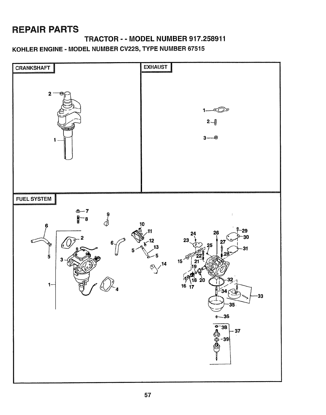
REPAIR PARTS
TRACTOR -- MODEL NUMBER 917.258911
KOHLER ENGINE- MODEL NUMBER CV22S, TYPE NUMBER 675"15
CFIANKSHAFT _
2
............ _ ,,.,,,,,,. ..... LiJJ,uu±,_.................,........
6
_-7 9
p8
26
10
_..E_XHAUST I
,,,, .............. " ' ,i ,iI ,,,'
24
23
13
16 17
26
e_.-36
o- 38 _37
-39
57
REPAIR PARTS
TRACTOR - -MODEL NUMBER 917.258911
KOHLER ENGINE -MODEL NUMBER CV22S, TYPE NUMBER 67515
FUEL SYSTEM
KEY PART
NO. NO. DESCRIPTION
1 24-853-25
2 24-04!-15
3 24-053-25
4 24-041_14
5 X-426-9
6 24-353-03
7 SM-0641060
8 M-0629095
9 47-154-01
10 24-t00-01
11 24-393-04
12 24-086-12
13 25-353-03
14 25-050-02
15 24-144-15
!6 24-468-05
17 24-241-01
!8 24-089-22
19 24-141-04
20 24-090-I0
21 24-089=24
22 24-086-19
23 24-462-02
24 24-086-20
25 24-337-27
26 24-337-11
27 24-086-22
28 24-089-23
29 24-086-21
30 24-096-13
3t 24-041-18
32 24-04t-19
33 24-757-05
34 24-369-01
35 24-234-01
36 24-337-28
37 24-755-15
38 24-041-21
39
NOT
Kit, Carburetor with Gasket
(Includes Key Numbers 2 thru 4)
Gasket, Carburetor
Carburetor Assembly (For
InformationOnly, Not Available
Separately) (includes 15-39)
Gasket, Air Cleaner Base
Clamp, Hose (6)
Line, Fuel, 10-5/8" (2)
Nut M8 x 1.0 (2)
Stud M6 x 1.O x 95 (2)
Clip, Cable
Nut, Plastic (2)
Pump, Fuel, Pulse
Screw, Hex Cap Head (2)
Line, Fuel, 13-1/2"
Filter, Fuel
Shaft, Choke
Washer
Collar, Choke
Spring, Choke Return
Ring, Choke Lever'
Lever, Choke
Spring, Throttle Adjust Screw
Screw, Throttle Adjust
Valve, Choke
Screw, Throttle and Choke Shaft (4)
Jet, Air Bleed
Jet, Slow
Screw, Idle Adjust
Spdng, Idle Adjust Screw
Screw (3)
Cover; Passage
Gasket, Passage Cover
Gasket, Float Chamber
Kit, Float Repair
Nozzle, Main
Chamber, Float
Jet, Main
Kit, Solenoid Valve (Includes 38-39)
Gasket, Chamber Screw
Gasket, Solenoid
ILLUSTRATED
24-041-15 Gasket, Carburetor
24-757-06 Kit, Carburetor Repair
24-755_72 Kit, High Altitude
(1500-3000 Meters)
24-755-73 Kit, High Altitude
(Over 3000 Meters)
CRANKSHAFT
KEY PART
NO. NO.
1 24-014-72
2 52-t39-09
DESCRIPTION
Crankshaft
Plug, Cup
EXHAUST
KEY PART
NO. NO. DESCRIPTION
1 24-041-02 Gasket, Exhaust (2)
2 M-0829033 Stud, Exhaust Manifold
M8 x 1.25 x 20 (4)
3 M-084t080 Nut, Muffler' Mounting
M8 x 1..25(4)
NOTILLUSTRATED
KEY PART
NO. NO. DESCRIPTION
-- 24-755_03 GasketSet
RPM Settings: Low Speed: 1150-1650
High Speed: 3200-3400
NOTE: AII component dimensions given in U.S. inches
1inch = 25A mm
58
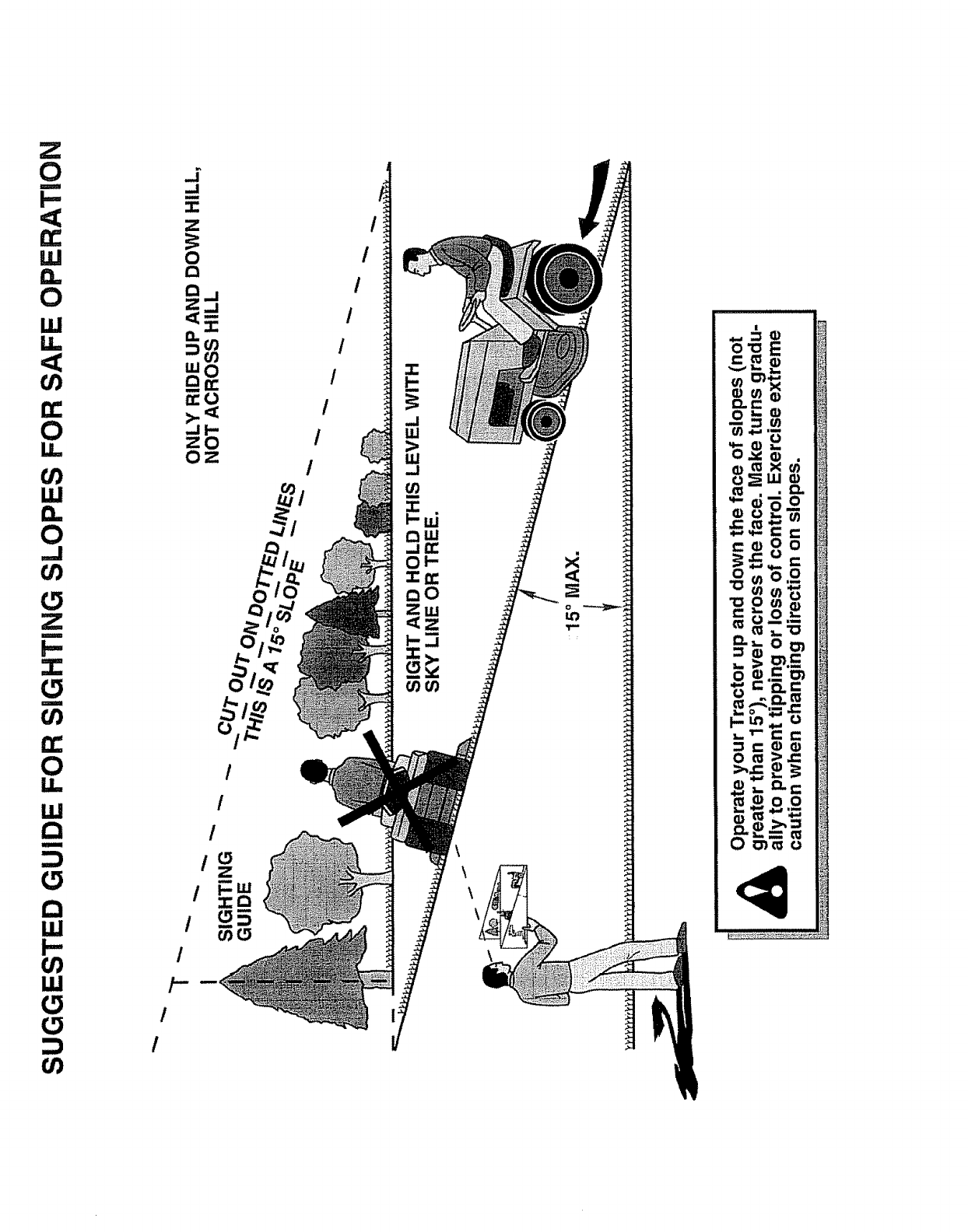
0
J
i--
D_
W
0
LI.I
flO
0
U)
W
n_
0
U)
Z
m
U)
0
u..
w
a
M
::1
W
I-
0')
O0
J
=J
n
-r-
Z
0
Z_j
0..
mO
OZ
/
/
/-
/
/
/
Z
0
oO
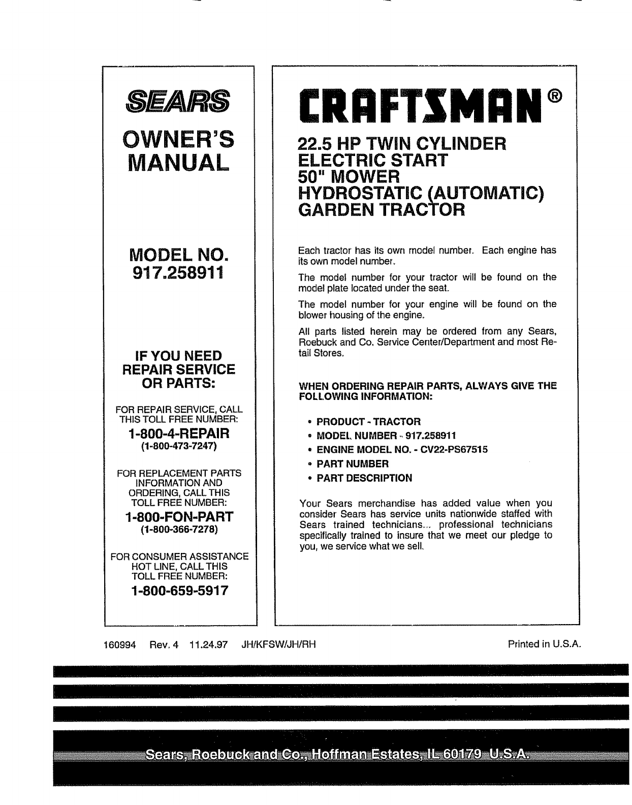
OWNER'S
AL
MODEL NO.
917.258911
IF YOU NEED
REPAIR SERVICE
OR PARTS:
FOR REPAIR SERVICE, CALL
THIS TOLL FREE NUMBER:
1-800-4-REPAIR
(1-800-473-7247)
FOR REPLACEMENT PARTS
INFORMATION AND
ORDERING, CALL THIS
TOLL FREE NUMBER:
1-800-FON-PART
(1-800-366-7278)
FOR CONSUMER ASSISTANCE
HOT LINE, CALL THIS
TOLL FREE NUMBER:
1-800-659-5917
£RRFTIMRN®
22.5 HP TWiN CYLINDER
ELECTRIC START
50" MOWER
HYDROSTATIC (AUTOMATIC)
GARDEN TRACTOR
Each tractor has its own model number,. Each engine has
its own model number.
The modei number for your tractor will be found on the
model plate located under the seat.
The model number' for your engine will be found on the
blower housing of the engine.
All parts listed herein may be ordered from any Sears,
Roebuck and Co, Service CenterJDepartment and most Re-
tail Stores°
WHEN ORDERING REPAIR PARTS, ALWAYS GIVE THE
FOLLOWING INFORMATION:
=PRODUCT -TRACTOR
• MODEl, NUMBER ,,917,258911
•ENGINE MODEL NO, -CV22-PS67515
°PART NUMBER
•PART DESCRIPTION
Your Sears merchandise has added value when you
consider +Sears has service units nationwide staffed with
Sears trained technicians ..... professional technicians
specifically trained to insure that we meet our+pledge to
you, we service what we sell.
160994 Rev. 4 11+24,97 JH/KFSW/JH!RH Printed in U,S.A.
,,,,,,, ,,, ,,,,,.,,,,,,,,,,,,,,,,,
