Craftsman 917 27077 Users Manual
917270770 917270770 CRAFTSMAN LAWN TRACTOR - Manuals and Guides 98120013 View the owners manual for your CRAFTSMAN LAWN TRACTOR #917270770. Home:Lawn & Garden Parts:Craftsman Parts:Craftsman LAWN TRACTOR Manual
CRAFTSMAN Lawn, Tractor Manual 98120013 CRAFTSMAN Lawn, Tractor Owner's Manual, CRAFTSMAN Lawn, Tractor installation guides
2015-01-05
: Craftsman Craftsman-917-27077-Users-Manual-160809 craftsman-917-27077-users-manual-160809 craftsman pdf
Open the PDF directly: View PDF ![]() .
.
Page Count: 60

Owner's Manual
rRI:IFTSMI:IN
19.0 HP
ELECTRIC START
42" MOWER
6 SPEED TRANSAXLE
LAWN TRACTOR
Model No.
917.270770
•Safety
•Assembly
•Operation
•Maintenance
•Repair Parts
CAUTION:
Read and follow all
Safety Rules and Instructions
before operating this equip-
ment.
For answers to your questions
about this product, Call:
1-800-659-5917
Sears Craftsman Help Line
5 am -5 pm, Mon- Sat
Sears, Roebuck and Co., Hoffman Estates, IL 60179
Warra_y..,.;.....;_ ...... _....;........ .................. 2
Safety Rules ..::;;..;...; ...:..... :...... ............. 2
Produ_ S_if_ahons _.,...:..,.,_.:. .......... 5
Assembly ................ J..:.,;._..._ ................. 8
Operation..'...... !,_ ...... _..... _.....1 ..... 11
Mainte_ianr_'I-_" Sch_ule .........' _,......_........ 17
Maintenance ......................................... 17
Service and Adjustments ...................... 21
Storage ................................................. 27
Troubleshooting .................................... 28
Repair Parts ......................................... 32
Parts Ordering ....................... Back Cover
LIMI" WARRAN'I_Y ON CRAFTSMAN RIDING EQUIPMENT
For two_(2) ; fro_rnt_e d_te--_ofpurchase, if this Craftsman Riding Equipment is main-
tained, iubr_cate_d ar_l tupedbp according to the instructions in the owner's manual
Sears _ill rePa,!"'or repla_ce, free of charge, any parts found to be defective in matenal or
workmanship. ! _ !
This Wb,rra_ty does not _over:.
•Expendable items which become worn during normal use, such as blades, spark
plugs, air cleaners, belts, etc.
•Tire replacement or repair caused by punctures from outside objects, such as nails,
thoms, stumps, or glass.
•Repairs necessary because of operator abuse, negligence, improper storage or acci-
dent or the failure to maintain the equipment according to the instructions contained in
the owner's manual.
•Riding equipment used for commercial or rental purposes.
LIMITED 90 DAY WARRANTY ON BA'r-rERY
For ninety (90) days from date of purchase, if any battery included with this riding equip-
ment proves defective in material or workmanship and our testing determines the bat-
tery will not hold a charge, Sears will replace the battery at no charge. In-home warranty
service on your Craftsman riding equipment is available at no charge for 30 days from
the date of purchase. Please contact your nearest service center. After 30 days from the
date of purchase, warranty service is available by taking your Craftsman dding equip-
ment to your nearest Sears Service Center. (In-home warranty service will still be avail-
able after 30 days from the date of purchase but a standard trip charge will apply). This
warranty applies only while this product is in the United States. This Warranty gives you
specific legal rights, and you may also have other rights which may vary from state to
state.
Sears, Roebuck and Co., D/817 WA, Hoffman Estates, IL 60179
GENERAL OPERATION _
•Read, understand, and follow all instruc-
tions in the manual and on the machine
before starting.
•Only allow responsible adults, _Nho are
familiar with the instructions, to operate
the machine.
•Clear the area of objects such as rocks,
toys, wire, etc., which could be picked
up and thrown by the blade.
•Be sure the area is clear of other people
before mowing. Stop machine if anyone -
enters the area.
2
•Never carry passengers.
•Do not mow in reverse unless absolute-
ly necessary. Always look down and
behind before and while backing.
•Be aware of the mower discharge direc-
tion and do not point it at anyone• Do
not operate the mower without either
the entire grass catcher or the guard in
place.
•Slow down before turning.
•Never leave a running machine unat-
tended. Always turn off blades, set park-
ing brake, stop engine, and remove
keys before dismounting.
•Turn off blades when not mowing.
•Stop engine before removing grass
catcher or unclogging chute.
•Mow only in daylight or good artificial
light.
•Do not operate the machine while under
the influence of alcohol or drugs.
•Watch for traffic when operating near or
crossing roadways.
•Use extra care when loading or unload-
ing the machine into a trailer or truck.
SLOPE OPERATION
Slopes are amajor factor related to loss-
of-control and tipover accidents, which
can result in severe injury or death. All
slepes require extra caution. If you cannot
back up the slope or if you feel uneasy on
it, do not mow it.
DO:
•Mow up and down slopes, not across.
•Remove obstacles such as rocks, tree
limbs, etc.
•Watch for holes, ruts, or humps. Uneven
terrain could overturn the machine. Tall
grass can hide obstacles.
•Use slow speed. Choose a low gear so
that you will not have to stop or shift
while on the slope.
•Follow the manufacturer's recommen-
dations for wheel weights or counter-
weights to improve stability.
•Use extra care with grass catchers or
other attachments. These can change
the stability of the machine.
•Keep all movement on the slopes slow
and gradual. Do not make sudden
changes in speed or direction.
•Avoid starting or stopping on a slope. If
tires lose traction, disengage the blades
and proceed slowly straight down the
slope.
DO NOT:
•Do notturn on slopes unless necessary,
and then, turn slowly and gradually
downhill, if possible.
•Do notmow near drop-offs, ditches, or
embankments. The mower could sud-
denly turn over if a wheel is over the
edge of a cliff or ditch, or if an edge
caves in.
•Do not mow on wet grass. Reduced
traction could cause sliding.
• Do nottry to stabilize the machine by
putting your foot on the ground.
•Do not use grass catcher on steep
slopes.
CHILDREN
Tragic accidents can occur if the operator
is not alert to the presence ofchildren.
Children are often attracted to the
machine and the mowing activity. Never
assume that children will remain where
you last saw them.
•Keep children out of the mowing area
and under the watchful care of another
responsible adult.
•Be alert and turn machine off if children
enter the area.
•Before and when backing, look behind
and down for small children.
• Never carry children. They may fall off
and be seriously injured or interfere with
safe machine operation.
•Never allow children to operate the
machine.
•Use extra care when approaching blind
comers, shrubs, trees, or other objects
that may obscure vision.
SERVICE
•Use extra care in handling gasoline and
other fuels. They are flammable and
vapors are explosive.
Use only an approved container.
Never remove gas cap or add fuel
with the engine running.Allow en-
gine to cool before refueling. Do not
smoke.
Never refuel the machine indoors.
- Never stere the machine or fuel
container inside where there is an
open flame, such as a water heater.
•Never run a machine inside a closed
area.
•Keep nuts and bolts, especially blade
attachment bolts, tight and keep equip-
ment in good condition.
•Never tamper with safety devices.
Check their proper operation regularly.
•Keep machine free of grass, leaves, or
other debris build-up. Clean oil or fuel
spillage. Allow machine to cool before
storing.
•Stop and inspect the equipment if you
strike an object. Repair, if necessary,
before restarting.
3
• Nevermakeadjustmentsor repairswith
the enginerunning.
•Grass catcher components are subject
to wear, damage, and deterioration,
which could expose moving parts or
allow objects to be thrown. Frequently
check components and replace with
manufacturer's recommended parts,
when necessary.
• Mower blades are sharp and can cut.
Wrap the blade(s) or wear gloves, and
use extra caution when servicing them.
•Check brake operation frequently.
Adjust and service as required.
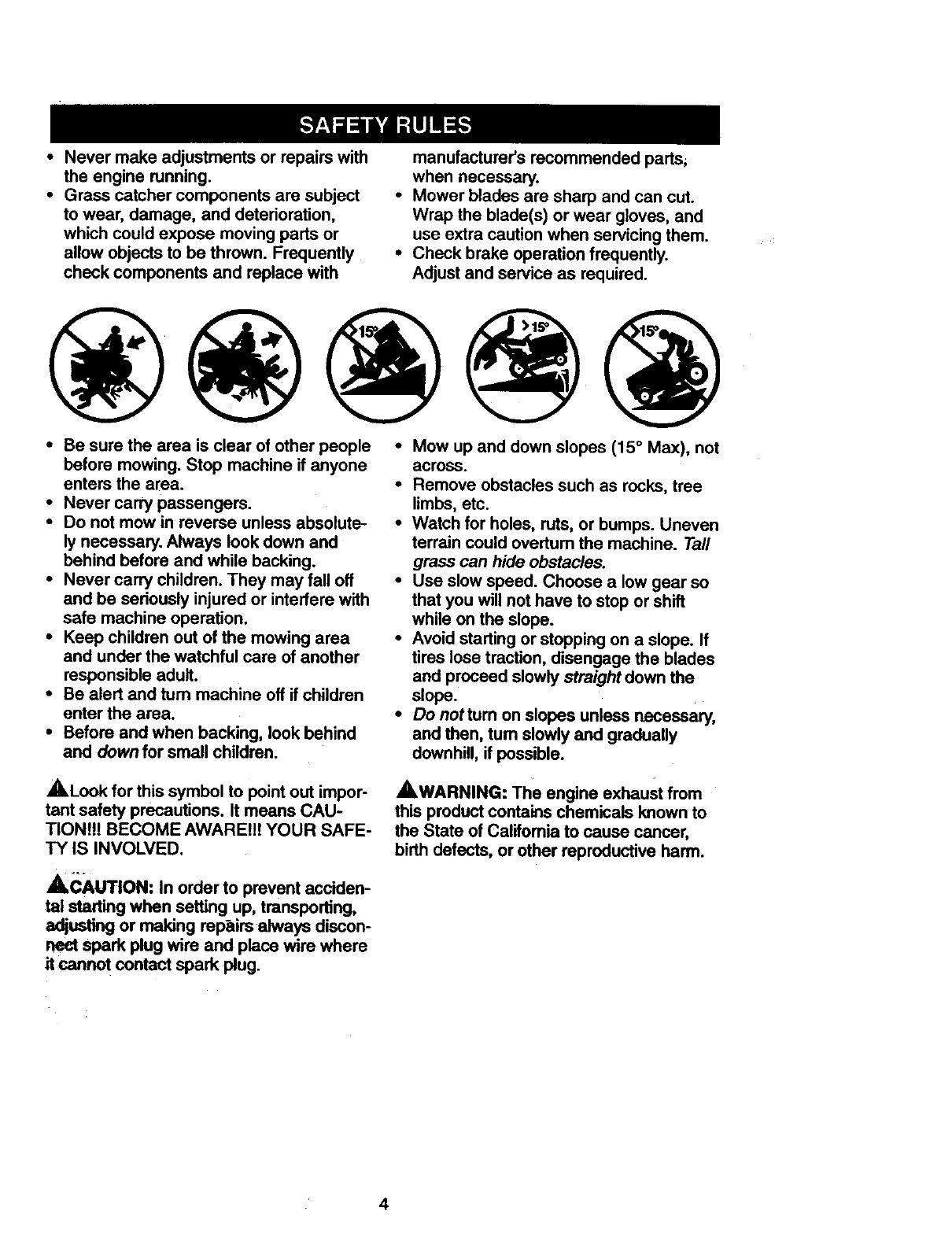
•Be sure the area is clear of other people •Mow up and down slopes (15 ° Max), not
before mowing. Stop machine if anyone
enters the area.
•Never carry passengers.
•Do not mow in reverse unless absolute-
ly necessary. Always look down and
behind before and while backing.
•Never carry children. They may fall off
and be seriously injured or interfere with
safe machine operation.
•Keep children out of the mowing area
and under the watchful care of another
responsible adult.
•Be alert and tum machine off if children
enter the area.
• Before and when backing, lock behind
and down for small children.
across.
•Remove obstacles such as rocks,tree
limbs, etc.
•Watch for holes, ruts, or bumps. Uneven
terrain could overturn the machine. Tall
grass can hide obstacles.
•Use slow speed. Choose a low gear so
that you will not have to stop or shift
while on the slope.
•Avoid starting or stopping on a slope. If
tires lose traction, disengage the blades
and proceed slowly straight down the
slope.
• Do nottum on slopes unless necessary,
and then, tum slowly and gradually
downhill, if possible.
_.Look for this symbol to point out impor-
tant safety precautions. It means CAU-
TIONI!! BECOME AWARE!!!l YOUR SAFE-
TY IS INVOLVED.
ACAUTION: In order to prevent acciden-
tal starting when setting up, transporting,
adjusting or making repairs always discon-
nect spark plug wire and place wire where
it cannot contact spark plug.
AWARNING: The engine exhaust from
this productcontains chemicals known to
the State of Califomia to cause cancer,
birth defects, or other reproductive harm.
4
PRODUCT SPECIFICATIONS
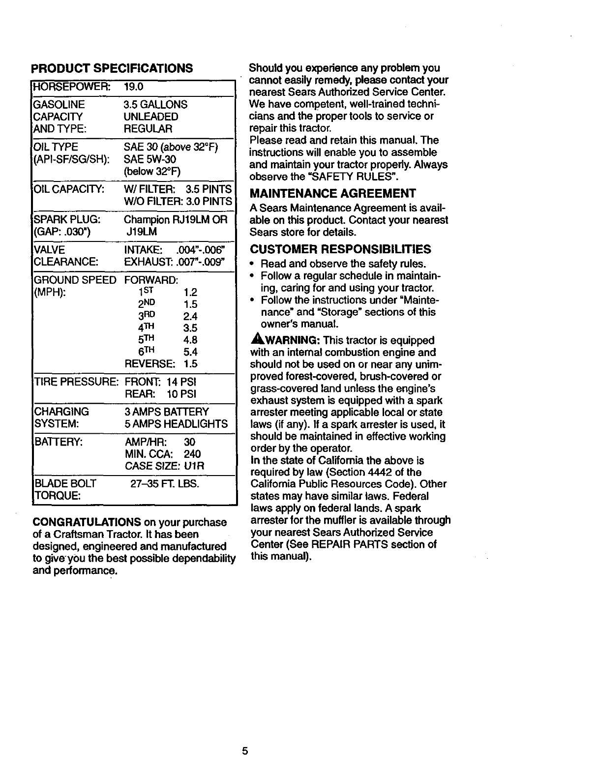
HORSEPOWER: 19.0
GASOLINE 3.5 GALLONS
CAPACITY UNLEADED
AND TYPE: REGULAR
OIL TYPE SAE 30 (above 32°F)
API-SF/SG/SH): SAE 5W-30
(below 32°F)
OIL CAPACITY: W/FILTER: 3.5 PINTS
W/O FILTER: 3.0 PINTS
SPARK PLUG: Champion RJt9LM OR
GAP: .030") J19LM
VALVE INTAKE: .004"-.006"
CLEARANCE: EXHAUST." .0(0-.009"
GROUND SPEED
(MPR):
FORWARD:
1sT 1.2
2 ND 1.5
3 RD 2.4
4TM 3.5
5TM 4.8
6TM 5.4
REVERSE: 1.5
TIRE PRESSURE: FRONT: 14 PSI
REAR: 10 PSI
CHARGING 3AMPS BATTERY
SYSTEM: 5 AMPS HEADLIGHTS
BATFERY: AMP/HR: 30
MIN. CCA: 240
CASE SIZE: U1R
BLADE BOLT 27-35 FT. LBS.
TORQUE:
CONGRATULATIONS on your purchase
of a Craftsman Tractor. It has been
designed, engineered and manufactured
to giveyou the best possibledependability
and performance.
Should you experience any problem you
cannot easily remedy, please contact your
nearest Sears Authorized Service Center.
We have competent, well-trained techni-
cians and the proper tools to service or
repair this tractor.
Please read and retain this manual. The
instructions will enable you to assemble
and maintain your tractor properly. Always
observe the =SAFETY RULES".
MAINTENANCE AGREEMENT
A Sears Maintenance Agreement is avail-
able on this product. Contact your nearest
Sears store for details.
CUSTOMER RESPONSIBILITIES
• Read and observe the safety rules.
• Follow a regular schedule in maintain-
ing, caring for and using your tractor.
•Follow the instructions under "Mainte-
nance" and "Storage" sections of this
owner's manual.
_,WARNING: This tractor is equipped
with an internal combustion engine and
should not be used on or near any unim-
proved forest-covered, brush-covered or
grass-covered land unless the engine's
exhaust system is equipped with a spark
arrester meeting applicable local or state
laws (if any). If aspark arrester is used, it
should be maintained in effective working
order by the operator.
In the state of Califomia the above is
required by law (Section 4442 of the
Califomia Public Resources Code). Other
states may have similar laws. Federal
laws apply on federal lands. Aspark
arrester for the muffler is available through
your nearest Sears Authorized Service
Center (See REPAIR PARTS section of
this manual).
5
II II I I
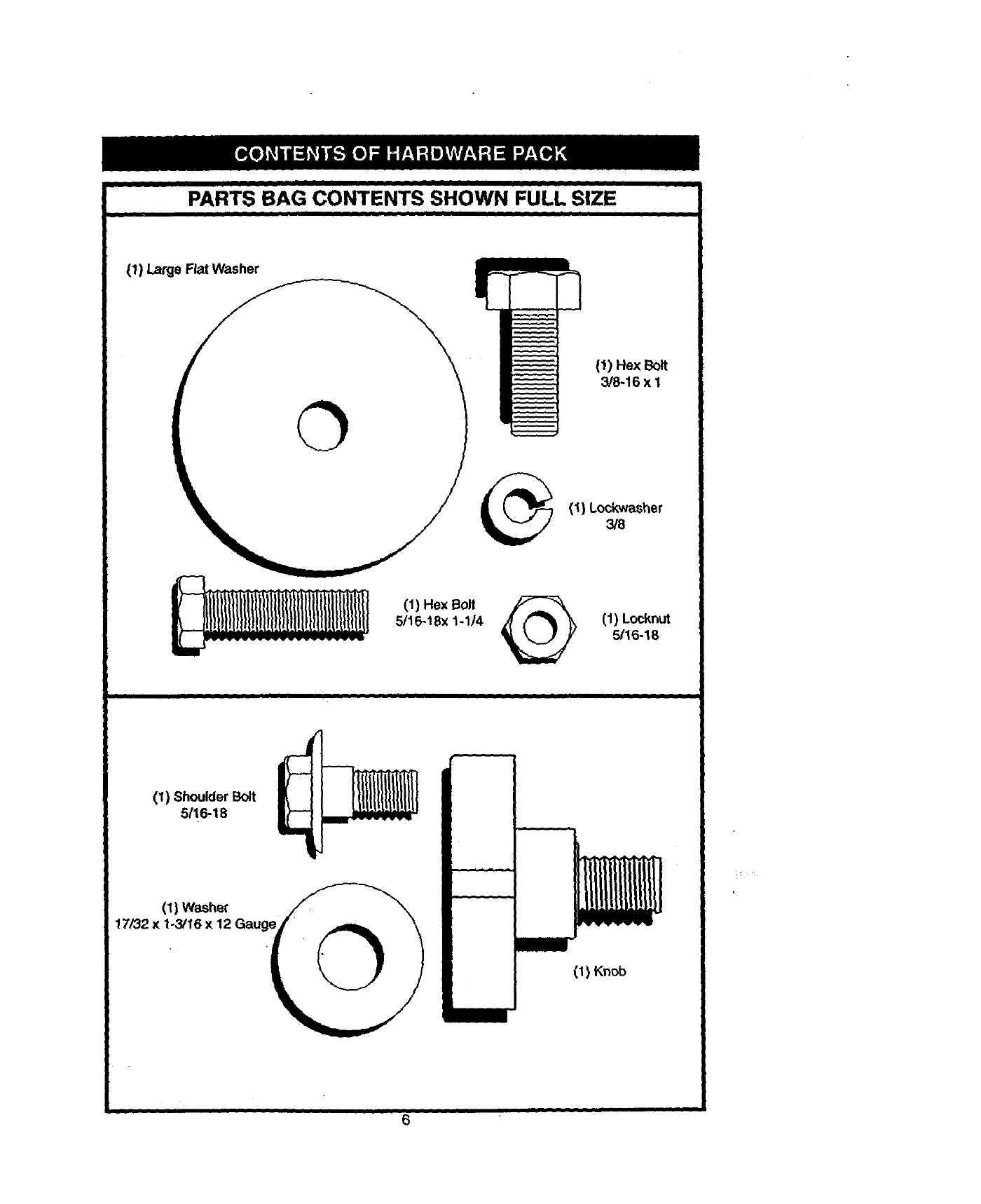
PARTS BAG CONTENTS SHOWN FULL SIZE
iIi I
(1) Large Flat Washer
(1) Hex 13olt
3/8-16 x I
(1) Lockwasher
318
(1) Hex Bolt
5116-18x 1-1/'4 @(1) Locknut
5/16-18
(1) Shoulder Bolt
5/16-18
(1) Washer
17/32 x 1o3/16 x 12 Gauge
(I) Knob
I6
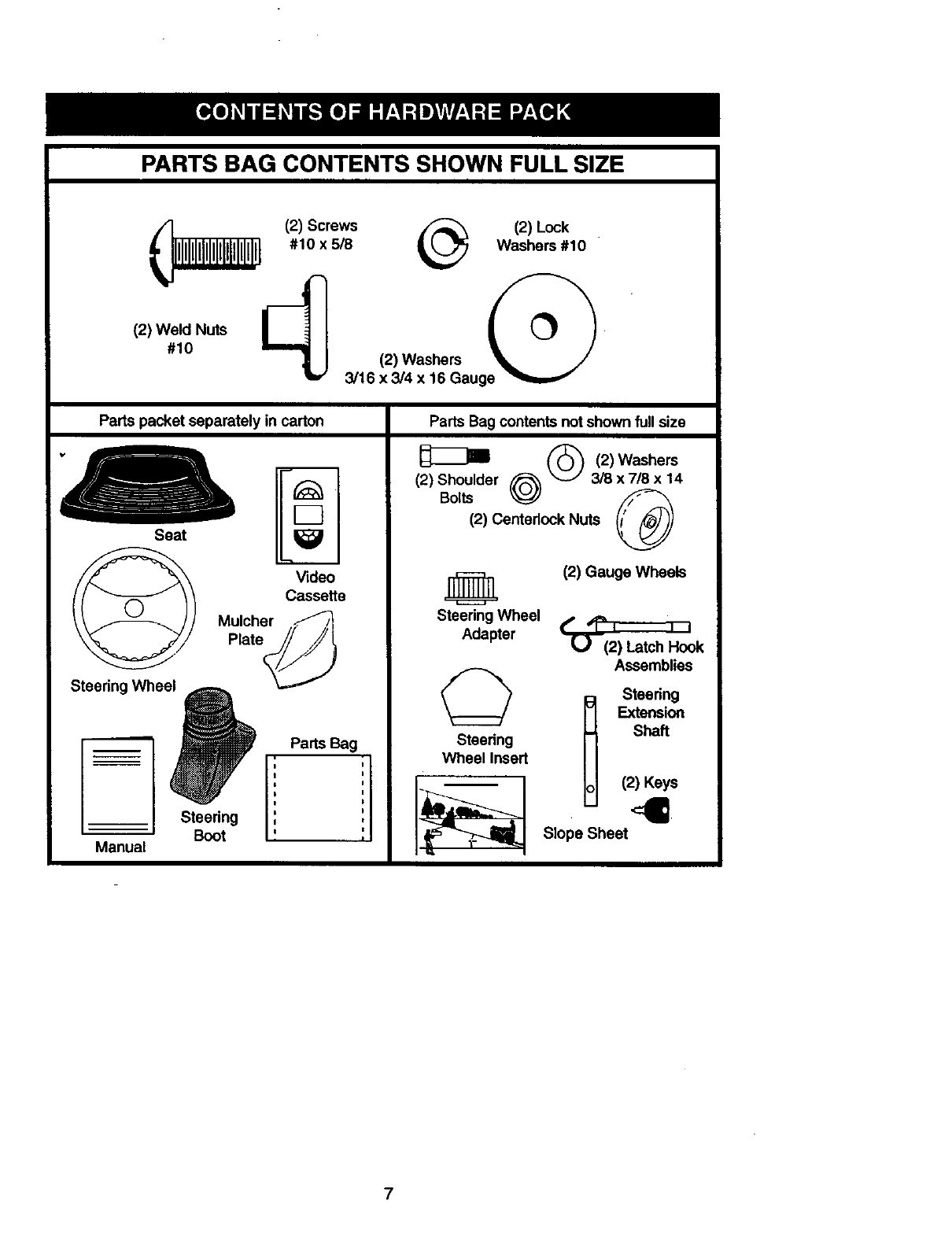
PARTS BAG CONTENTS SHOWN FULL SIZE
(2) Weld Nuts
#10
f(2) Screws /_ (2) Lock
i, _ #10x5/8 _Washers#10
(2) Washers
v3/16 x 3/4 x 16 Gauge
Parts packet separately in carton
_m
Seat
Video
Cassette
I Mulcher _/
Plate// /,
Steedng Whee_j_ ,"
Steedng ,
t
' Boot
Manual
Parts Bag
i
I
I
Parts Bag contents not shown full size
@@ , )Washers
(2) Shoulder 3/8 x 7/8 x14
Bolts
(2) Centedock Nuts ®
(2) Gauge Wheels
Steedng Wheel _Hook
Adapter
Assemblies
Steedng
Extension
Shaft
Steedng
Wheel Insert
(2) Keys
4
Slope Sheet
7
Yournewtractorhas beenassembledatthefactorywith exceptionof thosepartsleft
unassembledfor shipping purposes. To ensure safe and proper operation of your tractor
all parts and hardware you assemble must be tightened securely. Use the correct tools
as necessary to insure proper tightness. Review the video cassette before you begin.
TOOLS REQUIRED FOR •Position steering wheel so cross bars
ASSEMBLY are hodzontal (left to dght) and slide
inside boot and onto adapter.
A socket wrench set will make assembly •Assemble large flat washer, 3/8 lock
easier. Standard wrench sizes you need
are listed below.
(1) 9/16" wrench (2) 112" wrench
(1) Phillips Screw- (t) Pliers
ddver (1) "13repressure
(1) Utility knife gauge
(1) 3/4" Socket with ddve ratchet
When right or left hand is mentioned in
this manual, it means, from your point of
view, when you are in the operating posi-
tion (seated behind the steering wheel).
TO REMOVE TRACTOR FROM
CARTON
UNPACK CARTON
•Remove all accessible loose parts and
parts boxes from shipping carton (See
page 6).
•Cut, from togto bottom, along lines on
all four comers of shipping carton, and
lay panels flat.
•Check for any additional loose parts or
boxes and remove.
BEFORE ROLLING TRACTOR OFF
SKID
ATTACH STEERING WHEEL
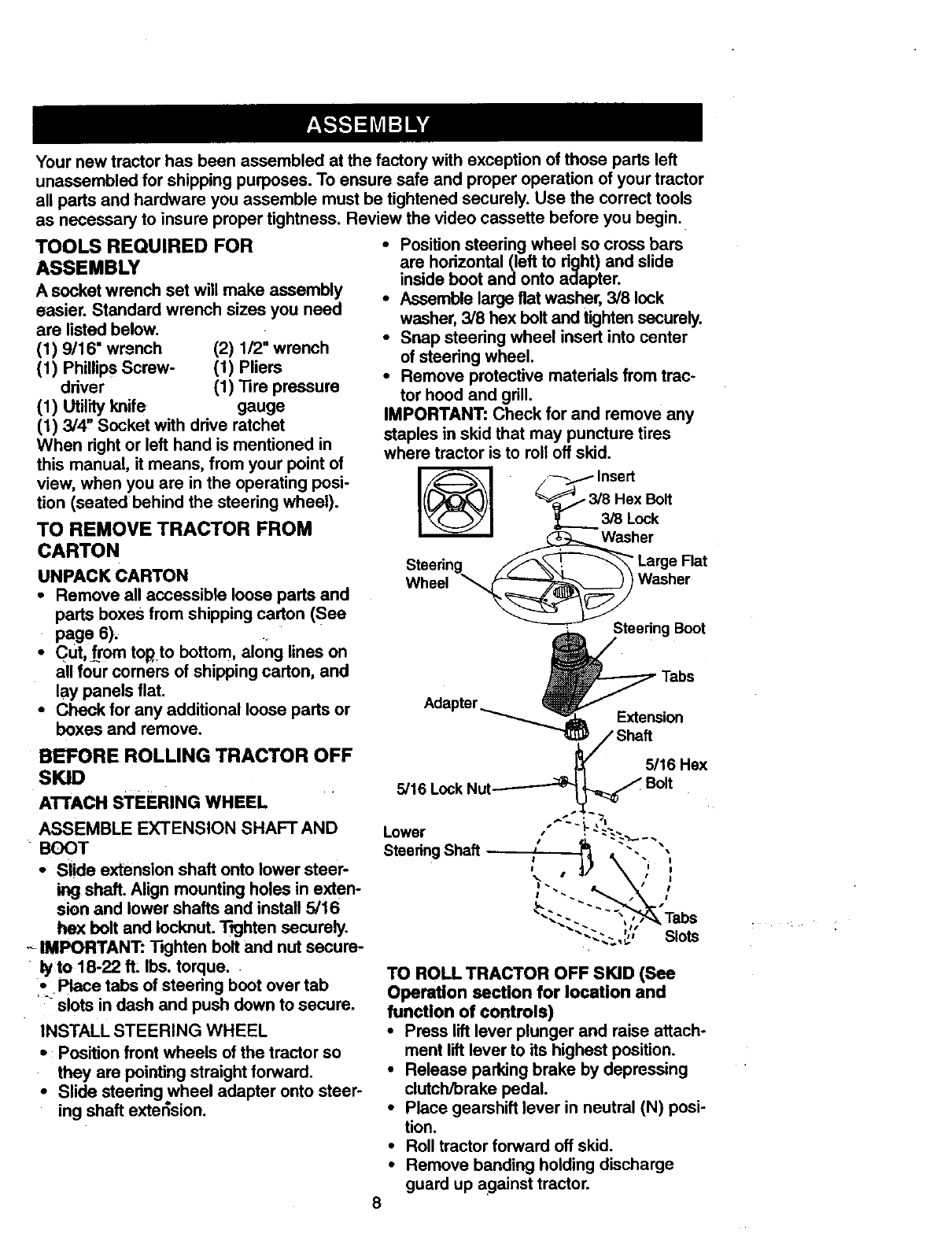
ASSEMBLE EXTENSION SHAFT AND
BOOT
°Slide extension shaft onto lower steer-
ing shaft,Align mounting holes in exten-
sion and lower shafts and install 5/16
hex bolt and Iocknut. Tighten securely.
,- IMPORTANT: 13ghten bolt and nut secure-
lyto 18-22 ft: Ibs. torque.
•Place tabs of steering boot over tab
slots in dash and push down to secure.
INSTALL STEERING WHEEL
•: Position front wheels of the tractor so
they are pointingstraight forward.
•Slide steedng wheel adapter onto steer-
ing shaft extension.
washer, 3/8 hex bolt and tighten securely.
•Snap steering wheel insert into center
of steering wheel.
•Remove protective materials from trac-
tor hood and grill.
IMPORTANT: Check for and remove any
staples in skid that may puncture tires
where tractor is to roll off skid.
@
Steering f/_._.=; _"_ Large Flat
Wheel _Washer
Steering Boot
Extension
_/Shaft
__5/16 Hex
5/16 Lock Nut_ Bolt
Lower ,.-----
SteeringShaft ;".. ;
\• ' :
",." - Tabs
"--_Slots
TO ROLL TRACTOR OFF SKID (See
Operation section for location and
function of controls)
•Press lift lever plunger and raise attach-
ment lift lever to its highest position.
•Release parking brake by depressing
clutch/brake pedal.
•Place gearshift lever in neutral (N) posi-
tion.
•Roll tractor forward off skid.
•Remove banding holding discharge
guard up against tractor.
HOW TO SET UP YOUR TRACTOR
CONNECT BATTERY
•Lift hood to raised position.
•If this battery is put into service after
month and year indicated on label (label
located between terminals) charge bat-
tery for minimum of one hour at 6-10
amps. (See "BAI-I-ERY" in
MAINTENANCE section of this manual
for charging instructions).
"
.- ... .. Label
•. .) _
_.:.
INSTALL SEAT
Adjust seat before tightening adjustment
knob.
•Remove cardboard packing on seat pan.
•Place seat on seat pan and assemble
shoulder bolt. Tighten shoulder bolt
securely.
•Assemble adjustment knob and flat
washer loosely. Do not tighten.
•Lower seat into operating position and
sit on seat.
•Slide seat until a comfortable position is
reached which allows you to press
clutch/brake pedal all the way down.
•Get off seat without moving its adjusted
position.
•Raise seat and tighten adjustment knob
securely.
Seat Pan S_
Sh0ulder /:_,_ _/
Bolt
Knob
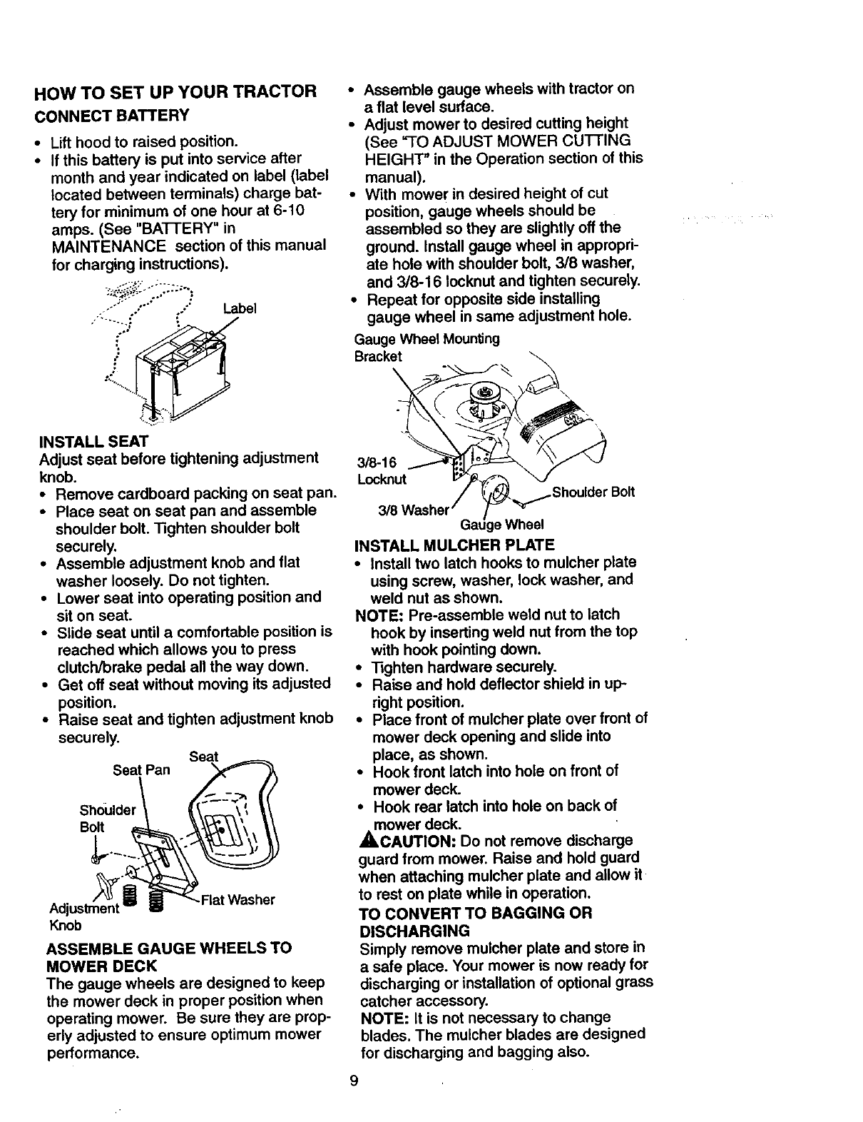
ASSEMBLE GAUGE WHEELS TO
MOWER DECK
The gauge wheels are designed to keep
the mower deck in proper position when
operating mower. Be sure they are prop-
erly adjusted to ensure optimum mower
performance.
•Assemble gauge wheels with tractor on
aflat level surface.
•Adjust mower to desired cutting height
(See "TO ADJUST MOWER CUTTING
HEIGHT" in the Operation section of this
manual).
•With mower in desired height of cut
position, gauge wheels should be
assembled so they are slightly off the
ground. Install gauge wheel in appropri-
ate hole with shoulder bolt, 3/8 washer,
and 3/8-16 Iocknut and tighten securely.
•Repeat for opposite side installing
gauge wheel in same adjustment hole.
Gauge Wheel Mounl_ng
Bracket
°
3/8-16
Locknut rBolt
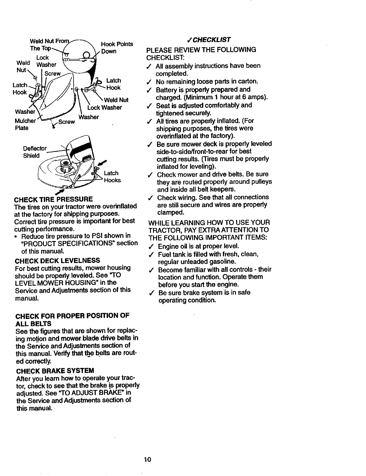
INSTALL MULCHER PLATE
•Install two latch hooks to mulcher plate
using screw, washer, lock washer, and
weld nut as shown.
NOTE: Pre-assemble weld nut to latch
hook by inserting weld nut from the top
with hook pointing down.
•Tighten hardware securely.
•Raise and hold deflector shield in up-
right position.
•Place front of mulcher plate over front of
mower deck opening and slide into
place, as shown.
•Hook front latch into hole on front of
mower deck.
•Hook rear latch into hole on back of
mower deck.
_,CAUTION: Do not remove discharge
guard from mower. Raise and hold guard
when attaching mulcher plate and allow it
to rest on plate while in operation.
TO CONVERT TO BAGGING OR
DISCHARGING
Simply remove mulcher plate and store in
a safe place. Your mower is now ready for
discharging or installation of optional grass
catcher accessory.
NOTE: it is not necessary to change
blades. The muicher blades are designed
for discharging and bagging also.
WeldNutFmrn._---_.
_. - "-7 "_ Hook Points
me Iop_/ _ Down
Lock ¥
Weld Washer _'_'|
Nut . !
• . h _,_ // /I ,_Latch
LaTc ._ _,.U/ //I J _H k
Was o, 7J Loc.W ,her
Mulcher .====_,_Screw Washer
Plate _
Deflector.__
Shleld_,_,,,
_" --_._/,_/_ Latch
\'*_=__ Hooks
j,,
CHECK TIRE PRESSURE
The tires on your tractor were overinflated
at the factory for shipping purposes.
Correct fire pressure is important for best
cutting performance.
•Reduce tire pressure to PSI shown in
"PRODUCT SPECIFICATIONS" section
of this manual.
CHECK DECK LEVELNESS
For best cutting results, mower housing
should be propedy leveled. See "TO
LEVEL MOWER HOUSING" in the
Service and Adjustments section of this
manual.
CHECK FOR PROPER POSITION OF
ALL BELTS
See the figures that are shown for replac-
ing moron and mower blade drive belts in
the Service and Adjustments section of
this manual. Verify that th_ebelts are rout-
ed correctly.
CHECK BRAKE SYSTEM
After you learn how to operate your trac-
tor, check to see that the brake (s properly
adjusted. See =TO ADJUST BRAKE" in
the Service and Adjustments section of
this manual.
#CHECKLIST
PLEASE REVIEW THE FOLLOWING
CHECKLIST:
,/ All assembly instructions have been
completed.
#No remaining loose parts in carton.
#Battery is properly prepared and
charged. (Minimum 1 hour at 6 amps).
•/ Seat is adjusted comfortably and
tightened securely.
#All tires are propedy inflated. (For
shipping purposes, the tires were
ovednflated at the factory).
,/ Be sure mower deck is properly leveled
side-to-side/front-to-rear for best
cutting results. (]ires must be prepedy
inflated for leveling).
,/ Check mower and drive belts. Be sure
they are routed properly around pulleys
and inside all belt keepers.
,/ Check wiring. See that all connections
are still secure and wires are properly
clamped.
WHILE LEARNING HOW TO USE YOUR
TRACTOR, PAY EXTRAATTENTION TO
THE FOLLOWING IMPORTANT ITEMS:
,/ Engine oil is at proper level.
•/Fuel tank is filled with fresh, clean,
regular unleaded gasoline.
#Become familiar with all controls - their
location and function. Operate them
before you start the engine.
#' Be sure brake system is in safe
operating condition.
10
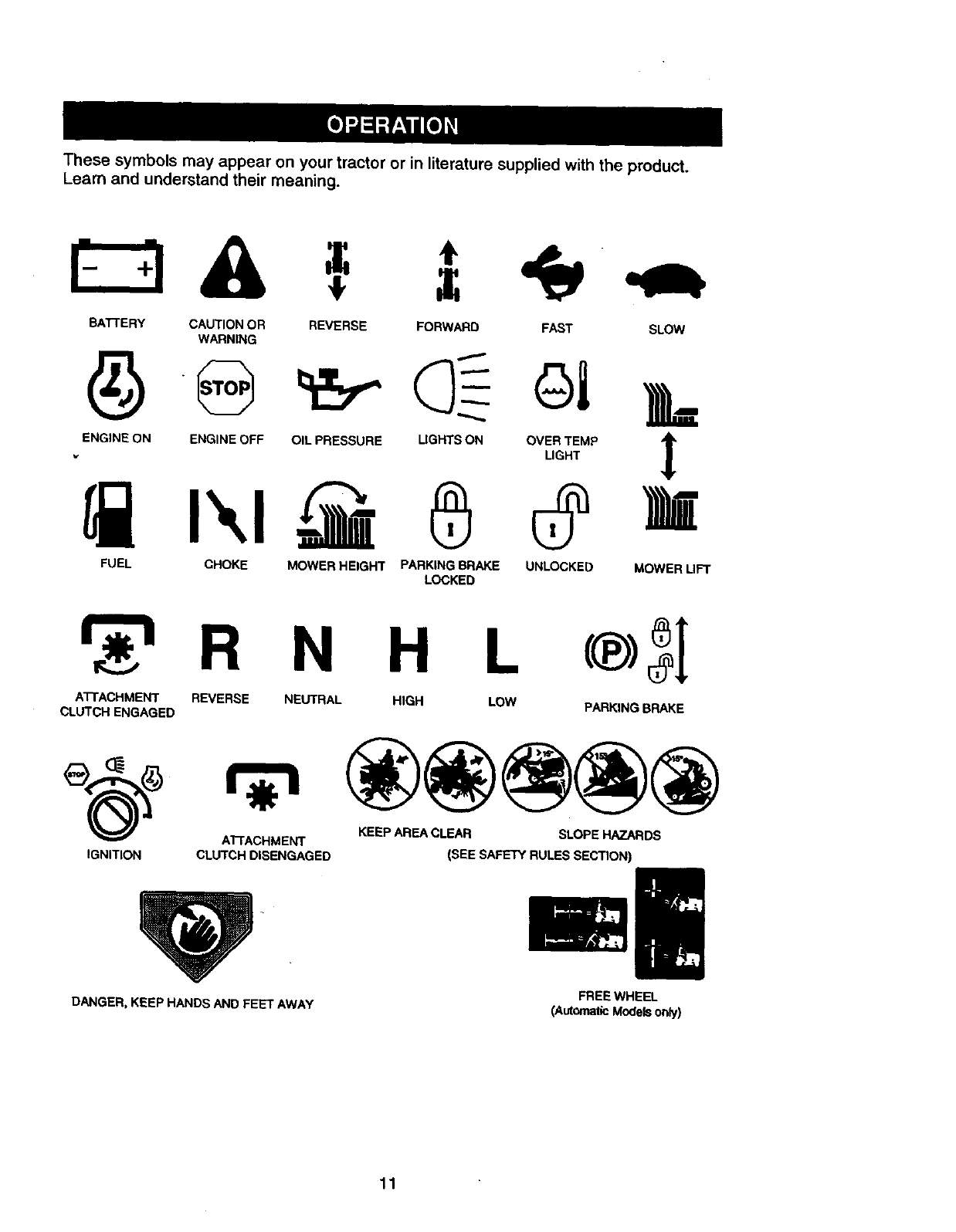
These symbols may appear on your tractor or in literature supplied with the product.
Learn and understand their meaning.
BA'T-rERY CAUTION OR REVERSE FORWARD FAST SLOW
WARNING
FUEL CHOKE MOWER HEIGHT PARKING BRAKE UNLOCKED MOWER UFT
LOCKED
R N H L
A'I-rACHMENT REVERSE NEUTRAL HIGH LOW
CLUTCH ENGAGED PARKING BRAKE
A'T-rACHMENT KEEP AREA CLEAR SLOPE HAZARDS
IGNITION CLUTCH DISENGAGED (SEE SAFETY RULES SECTION)
DANGER, KEEP HANDS AND FEET AWAY FREE WHEEL
(Automatic Modelsonly)
11
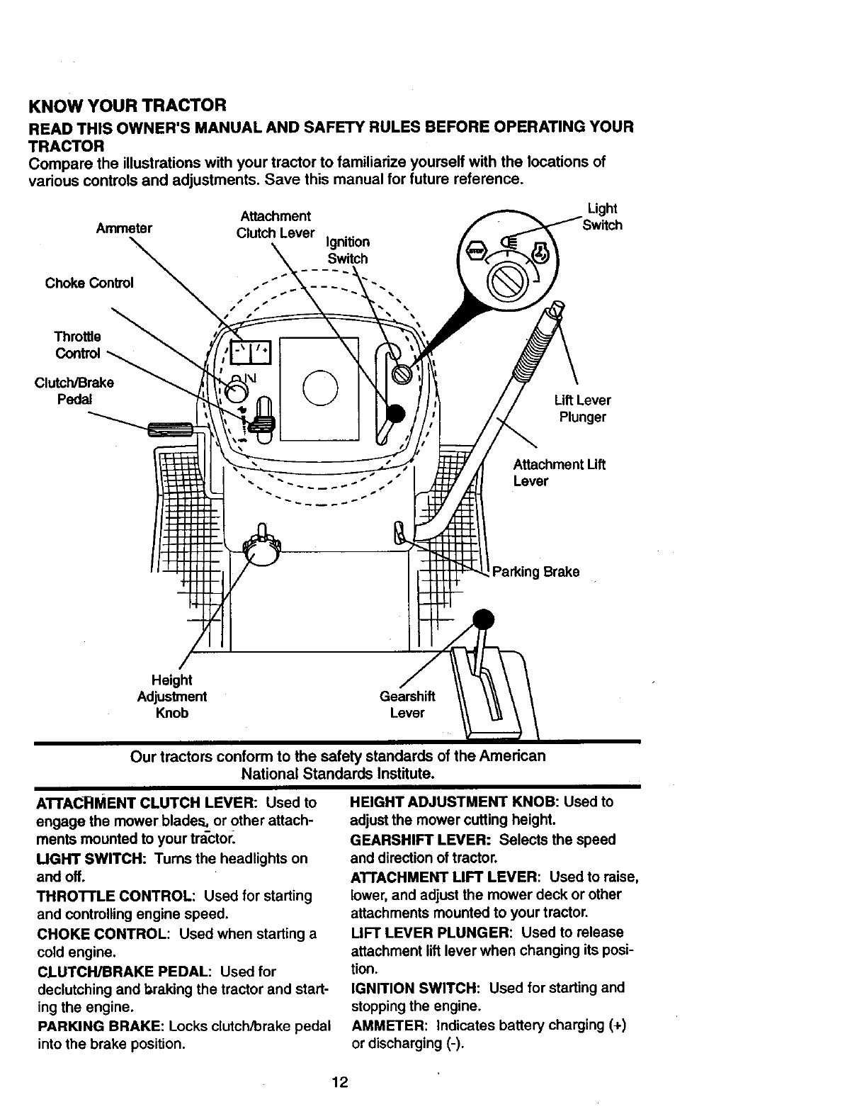
KNOW YOUR TRACTOR
READTHISOWNER'SMANUALANDSAFETYRULESBEFOREOPERATINGYOUR
TRACTOR
Comparethe illustrationswithyourtractorto familiarizeyourselfwiththe locationsof
variouscontrolsandadjustments.Savethis manualfor future reference.
Attachment
Ammeter Clutch Lever Ignition
Switch
Light
Choke Control
Throttle
Control
Clutch/Brake
Pedal Lift Lever
Plunger
Attachment Uft
Lever
Brake
Height
Adjustment Gearshift
Our tractors conform to the safety standards of the American
National Standards Institute.
AI"rAcFIMENT CLUTCH LEVER: Used to
engage the mower blades, or other attach-
ments mounted to your tr_ctor_
UGHT SWITCH: Turns the headlights on
and off.
THRO'rrLE CONTROL: Used for starting
and controlling engine speed.
CHOKE CONTROL: Used when starting a
cold engine.
CLUTCH/BRAKE PEDAL: Used for
declutching and braking the tractor and start-
ing the engine.
PARKING BRAKE: Locks clutch/brake pedal
into the brake position.
HEIGHT ADJUSTMENT KNOB: Used to
adjust the mower cutting height.
GEARSHIFT LEVER: Selects the speed
and direction of tractor.
AI"rACHMENT LIFT LEVER: Used to raise,
lower, and adjust the mower deck or other
attachments mounted to your tractor.
LIFT LEVER PLUNGER: Used to release
attachment lift lever when changing its posi-
tion.
IGNITION SWITCH: Used for starting and
stopping the engine.
AMMETER: Indicates battery charging (+)
or discharging (-).
12
The operationof anytractor can result in foreign objects thrown into the
eyes, which can result in severe eye damage. Always wear safety glass-
es or eye shields while operating your tractor or performing any adjust-
ments or repairs. We recommend a wide vision safety mask over specta-
cles, or standard safety glasses.
HOW TO USE YOUR TRACTOR
Your tractor is equipped with an operator
presence sensing switch. When engine
is running, any attempt by the operator to
leave the seat without first setting the
parking brake will shut off the engine.
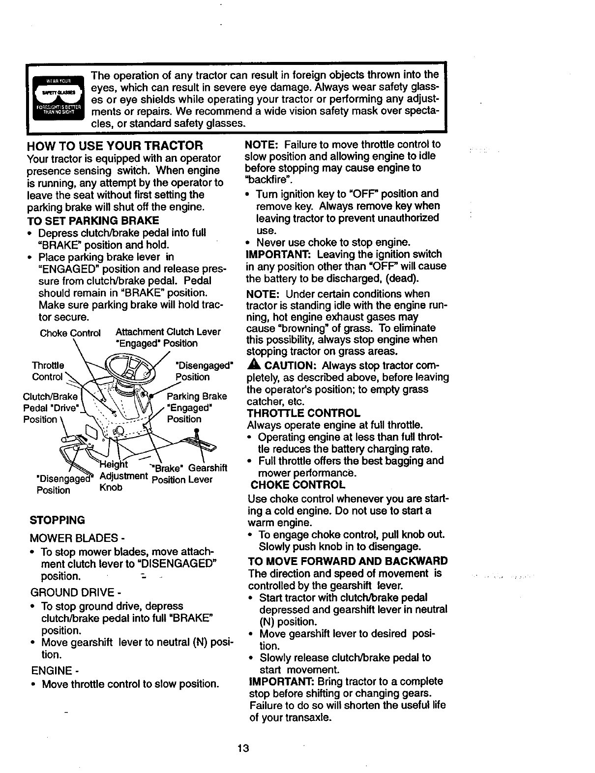
TO SET PARKING BRAKE
•Depress clutch/brake pedal into full
=BRAKE" position and hold.
•Place parking brake lever in
"ENGAGED" position and release pres-
sure from clutch/brake pedal. Pedal
should remain in "BRAKE" position.
Make sure parking brake will hold trac-
tor secure.
Choke Control Attachment Clutch Lever
"Engaged" Position
Throttle "Disengaged"
Position
Parking Brake
Pedal "Drive" "Engaged"
Position Position
Position
"Brake" Gearshift
Adjustment Position Lever
Knob
STOPPING
MOWER BLADES -
•To stop mower blades, move attach-
ment clutch lever to "DISENGAGED"
position.
GROUND DRIVE-
•To stop ground drive, depress
clutch/brake pedal into full "BRAKE"
position.
•Move gearshift lever to neutral (N) posi-
tion.
ENGINE -
•Move throttle control to slow position.
NOTE: Failure to move throttle controlto
slow position and allowing engine to idle
before stopping may cause engine to
"backfire"
•Tum ignition key to =OFF" position and
remove key. Always remove key when
leaving tractor to prevent unauthorized
use.
•Never use choke to stop engine.
IMPORTANT: Leaving the ignition switch
in any position other than =OFF" will cause
the battery to be discharged, (dead).
NOTE: Under certain conditions when
tractor is standing idle with the engine run-
ning, hot engine exhaust gases may
cause "browning" of grass. To eliminate
this possibility, always stop engine when
stopping tractor on grass areas.
,A CAUTION: Always stop tractor com-
pletely, as described above, before leaving
the operator's position; to empty grass
catcher, etc.
THRO'R'LE CONTROL
Always operate engine at full throttle.
•Operating engine at less than full throt-
tle reduces the battery charging rate.
•Full throttle offers the best bagging and
mower performance.
CHOKE CONTROL
Use choke control whenever you are start-
ing acold engine. Do not use to start a
warm engine.
•To engage choke control, pull knob out.
Slowly push knob in to disengage.
TO MOVE FORWARD AND BACKWARD
The direction and speed of movement is
controlled by the gearshift lever.
•Start tractor with clutch/brake pedal
depressed and gearshift lever in neutral
(N) position.
•Move gearshift lever to desired posi-
tion.
•Slowly release clutch/brake pedal to
start movement.
IMPORTANT: Bring tractor to a complete
stop before shifting or changing gears.
Failure to do so will shorten the useful life
of your transaxle.
13
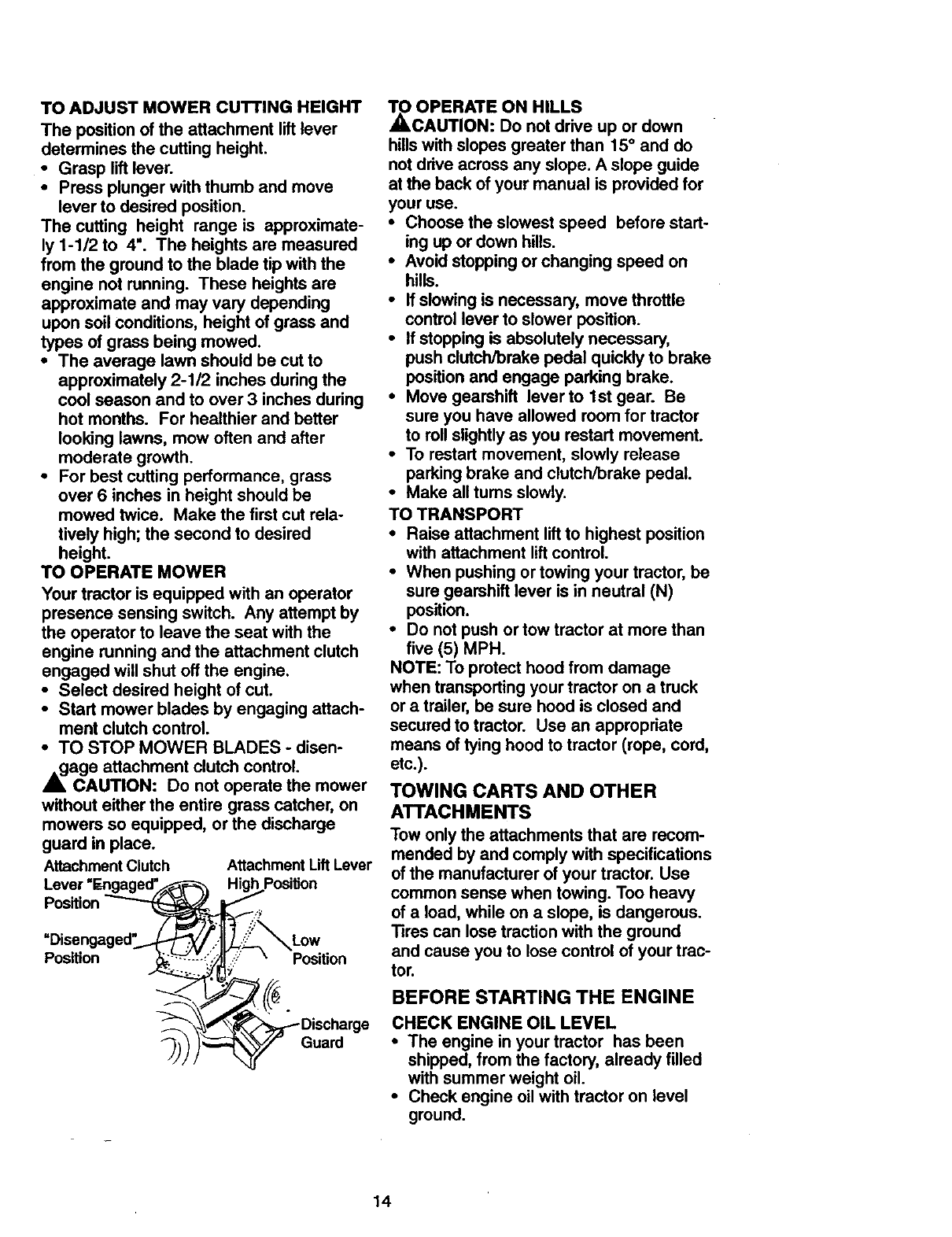
TOADJUSTMOWERCUTTINGHEIGHT
The positionof the attachmentliftlever
determinesthecuttingheight.
•Grasp lift lever.
•Press plunger with thumb and move
lever to desired position.
The cutting height range is approximate-
ly 1-1/2 to 4". The heights are measured
from the ground to the blade tip with the
engine not running. These heights are
approximate and may vary depending
upon soil conditions, height of grass and
types of grass being mowed.
•The average lawn should be cut to
approximately 2-1/2 inches during the
cool season and to over 3 inches during
hot months. For healthier and better
looking lawns, mow often and after
moderate growth.
• For best cutting performance, grass
over 6 inches in height should be
mowed twice. Make the first cut rela-
tively high; the second to desired
height.
TO OPERATE MOWER
Your tractor is equipped with an operator
presence sensing switch. Any attempt by
the operator to leave the seat with the
engine running and the attachment clutch
engaged will shut off the engine.
•Select desired height of cut.
•Start mower blades by engaging attach-
ment clutch control.
•TO STOP MOWER BLADES - disen-
,_age attachment clutch control.
CAUTION: Do not operate the mower
without either the entire grass catcher, on
mowers so equipped, or the discharge
guard in place.
Attachment Clutch Attachment Lift Lever
Lever "Engaged'F_-_--_ High Position
Position _ _
=Disengaged_..!---F'_ _'..._._j_Low
Position v f_L_-'i_ _ i_/-'_ Position
_j)) )_Guard
TO OPERATE ON HILLS
_,CAUTION: DO not drive up or down
hills with slopes greater than 15 ° and do
not drive across any slope. A slope guide
at the back of your manual is provided for
your use.
•Choose the slowest speed before start-
ing up or down hills.
•Avoid stopping or changing speed on
hills.
•If slowing is necessary, move throttle
control lever to slower position.
•If stopping is absolutely necessary,
push clutch/brake pedal quickly to brake
position and engage parking brake.
•Move gearshift lever to 1st gear. Be
sure you have allowed room for tractor
to roll slightly as you restart movement.
•To restart movement, slowly release
parking brake and clutch/brake pedal.
•Make all tums slowly.
TO TRANSPORT
•Raise attachment lift to highest position
with attachment lift control.
•When pushing or towing your tractor, be
sure gearshift lever is in neutral (N)
position.
•Do not push or tow tractor at more than
five (5) MPH.
NOTE: To protect hood from damage
when transporting your tractor on a truck
or a trailer, be sure hood is closed and
secured to tractor. Use an appropriate
means of tying hood to tractor (rope, cord,
etc.).
TOWING CARTS AND OTHER
ATTACHMENTS
Tow onlythe attachments that are recom-
mended by and comply with specifications
ofthe manufacturer of your tractor. Use
common sense when towing. Too heavy
of aload, while on a slope, is dangerous.
Tires can lose tractionwith the ground
and cause you to lose control of your trac-
tot.
BEFORE STARTING THE ENGINE
CHECK ENGINE OIL LEVEL
•The engine in your tractor has been
shipped, from the factory, already filled
with summer weight oil.
•Check engine oil with tractor on level
ground.
14
•Remove oil till cap/dipstick and wipe
clean, minsert the dipstick and screw
cap tight, wait for a few seconds,
remove and read oil level. If necessary,
add oil until "FULL" mark on dipstick is
reached. Do not overfill.
• For cold weather operation you should
change oil for easier starting (See "OIL
VISCOSITY CHAR-r" in the Mainten-
ance section of this manual).
•To change engine oil, see the Mainten-
ance section in this manual.
ADD GASOLINE f
•Fill fuel tank. Use fresh, clean, regular
unleaded gasoline with a minimum of 87
octane. (Use of leaded gasoline will
increase carbon and lead oxide
deposits and reduce valve life). Do not
mix oil with gasoline. Purchase fuel in
'quantities that can be used within 30
days to assure fuel freshness.
IMPORTANT: When operating in tempera-
tures below 32°F(0°C), use fresh, clean
winter grade gasoline to help insure good
_dweather starting.
ARNING: Experience indicates that
alcohol blended fuels (called gasohol or
using ethanol or methanol) can attract
moisture which leads to separation and
formation of acids during storage. Acidic
gas can damage the fuel system of an
engine while in storage. To avoid engine
problems, the fuel system should be emp-
tied before storage of 30 days or longer.
Drain the gas tank, start the engine and let
it run until the fuel lines and carburetor are
empty. Use fresh fuel next season. See
Storage Instructions for additional informa-
tion. Never use engine or carburetor
cleaner products in the fuel tank or perma-
_nct damage may occur.
AUTI_ON: Fill to bottom of gas tank
filler neck. Do not overfill. Wipe off any
spilled oil or fuel. Do not.store, spill or use
gasoline near an open fl_me.
TO START ENGINE
When starting the engine for the first time
or if the engine has run out of fuel, it will
take extra cranking time to move fuel from
the tank to the engine.
•Sit on seat in operating position,
depress clutch/brake pedal and set
parking brake.
•Place gear shift lever in neutral (N)
position.
•Move attachment clutch to "DISEN-
GAGED" position.
• Move throttle control to fast position
•Pull choke control out for a cold engine
start attempt. For a warm engine start
attempt the choke control may not be
needed.
NOTE: Before starting, read the warm and
cold starting procedures below.
•Insert key into ignitionand turn key
clockwise to "START" position and
release key as soon as engine starts.
Do not run starter continuously for more
than fifteen seconds per minute. If the
engine does not start after several
attempts, push choke control in, wait a
few minutes and try again. If engine still
does not start, pullthe choke control out
and retry.
WARM WEATHER STARTING (50 ° F
AND ABOVE)
• When engine starts, slowly push choke
control in until the engine begins to run
smoothly. If the engine starts to run
roughly, pull the choke control out slight-
ly for a few seconds and then continue
to push the control in slowly.
•The attachments and ground drive can
now be used. If the engine does not
accept the load, restart the engine and
allow it to warm up for one minute using
the choke as described above.
COLD WEATHER STARTING (50 °FAND
BELOW)
•When engine starts, slowly push choke
control in until the engine begins to run
smoothly. Continue to push the choke
control in small steps allowing the
engine to accept small changes in
speed and load, until the choke control
is fully in. If the engine starts to run
roughly, pull the choke control out slight-
ly for afew seconds and then continue
to push the control in slowly. This may
require an engine warm-up period from
several seconds to several minutes,
depending on the temperature.
•The attachments can be used during
the engine warm-up period and may
require the choke control be pulled out
slightly.
NOTE: Ahigh altitude (above 3000 feet)
or in cold temperatures (below 32 F) the
carburetor fuel mixture may need to be
adjusted for best engine performance.
See "-IO ADJUST CARBURETOR" in the
Service and Adjustments section of this
manual.
15
MOWING TIPS
• Mowershouldbeproperlyleveledfor
bestmowingperformance.See=TO
LEVEL MOWER HOUSING" in the
Service and Adjustments section of this
manual.
•The left hand side of mower should be
used for trimming.
•Drive so that clippings are discharged
onto the area that has been cut. Have
the cut area to the fight of the machine.
This will result in amore even distribu-
tion of clippings and more uniform cut-
ting.
•When mowing large areas, start by tum-
ing to the fight so that clippings will dis-
charge away from shrubs, fences, drive-
ways, etc. After one or two rounds,
mow in the opposite direction making
left hand turns until finished
•If grass is extremely tall, it should be
mowed twice to reduce load and possi-
ble fire hazard from dried clippings.
Make first cut relatively high; the second
to the desired height.
•Do not mow grass when it is wet. Wet
grass will plug mower and leave unde-
sirable clumps. Allow grass to dry
before mowing.
•Always operate engine at full throttle
when mowing to assure better mowing
performance and proper discharge of
material. Regulate ground speed by se-
lecting a low enough gear to give the
mower the best cutting performance as
well as the quality of cut desired.
•When operating attachments, select a
ground speed that will suit the terrain
and give best performance of the at-
tachment being used.
]D
¢--
MULCHING MOWING TIPS
IMPORTANT: For best performance,
keep mower housing free of built-up grass
and trash. Clean after each use.
•The special mulching blade will recut
the grass clippings many times and
reduce them in size so that as they fall
onto the lawn they will disperse into the
grass and not be noticed. Also, the
mulched grass will biodegrade quickly
to provide nutrients for the lawn.
Always mulch with your highest engine
(blade) speed as this will provide the
best recutting action of the blades.
•Avoid cutting your lawn when it is wet.
Wet grass tends to form clumps and
interferes with the mulching action. The
best time to mow your lawn is the early
afternoon. At this time the grass has
dried and the newly cut area will not be
exposed to the direct sun.
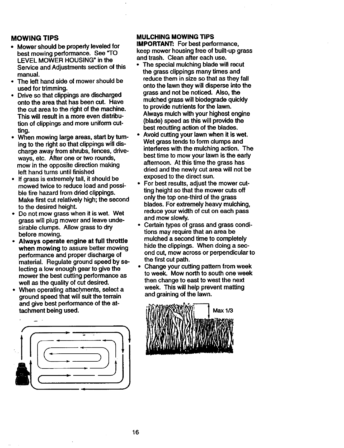
•For best results, adjust the mower cut-
ting height so that the mower cuts off
only the top one-third of the grass
blades. For extremely heavy mulching,
reduce your width of cut on each pass
and mow slowly.
• Certain types of grass and grass condi-
tions may require that an area be
mulched a second time to completely
hide the clippings. When doing a sec-
ond cut, mow across or perpendicular to
the first cut path.
•Change your cutting pattern from week
to week. Mow north to south one week
then change to east to west the next
week. This will help prevent matting
and graining of the lawn.
_i__i_l'__--__.. IVMax1/3
16
CUSTOMER RESPONSIBILITIES
FILL,. OATES
REGULAR SERVICE DAT E$
Check Operator Presence and
TInterlock Systems t# #
RCheck for Loose Fasteners II_ 1_7
: A Sharpen/Replace Mower Blades _4
iC Lubrication Chart )
O Check Battenj Level
RClean Battery and Terminals I1_
Check Transaxle Cooling If
Adjust Blade Belt(s) Tension I_s
Adjust Motion Drive BeN(s) TenSion (Ks
Check Engine Oil Level Vw
Change Engine Oil _.2.3 V°
EClean Air Filter
NClean Air Screen
IG Inspect Muffler/Spark Arrester V'
Replace Oil Filter (If equipped) =1_:
N Clean Engine Cooling Fins
Replace Spark Plug _I1_
Replace Air Filter Paper Cartridge ql_2
Replace Fuel Filter
1 - Change more often when operating under a heavy load or In hlg_ ambient tlmlpe_atures. 5 -if equipped _adorable system.
2 - Sen_tce more often when operating In dirty or dusty condlOons. 6 - Not re_Jked If equipped with malntenance-fr=e batlePj.
3°If equipped with ¢41filter, change (:41evePj 50 h_r=. 7 - Tighten front axkD pivot bolt to 35 ft.-II_, maximum.
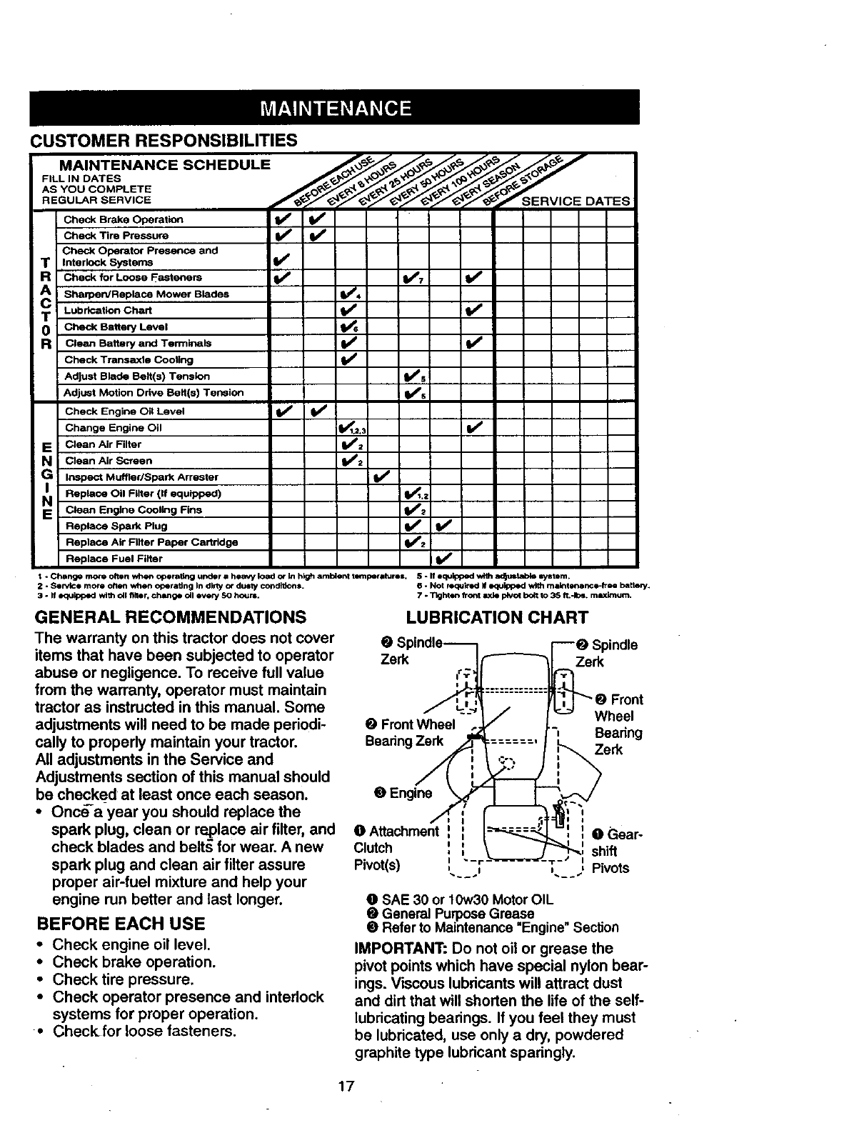
GENERAL RECOMMENDATIONS LUBRICATION CHART
The warranty on this tractor does not cover
items that have been subjected to operator
abuse or negligence. To receive full value
from the warranty, operator must maintain
tractor as instructed in this manual. Some
adjustments will need to be made periodi-
cally to properly maintain your tractor.
All adjustments in the Service and
Adjustments section of this manual should
be checked at least once each season.
•Once-a-year you should replace the
spark plug, clean or rePlace air filter, and
check blades and belt._ for wear. A new
spark plug and clean air filter assure
proper air-fuel mixture and help your
engine run better and last longer.
BEFORE EACH USE
• Check engine oil level.
• Check brake operation.
• Check tire pressure.
•Check operator presence and interlock
systems for proper operation.
• Checkfor loose fasteners.
Spindle
Zerk Zerk
Wheel
0FrontWheel
Bearing Zerk -_ Bearing
Zerk
@Engine
I
O Attachment : ( ) 0 Gear-
Clutch ' '
, _ shift
Pivot(s) ,._, ,_ , Pivots
O SAE 30 or 10w30 Motor OIL
•General Purpose Grease
•Refer to Maintenance "Engine" Section
IMPORTANT: Do not oil or grease the
pivot points which have special nylon bear-
ings. Viscous lubricants will attract dust
and dirt that will shorten the life of the self-
lubricating bearings. If you feel they must
be lubricated, use only a dry, powdered
graphite type lubricant spadngly.
17
TRACTOR
Alwaysobservesafetyruleswhenper-
forminganymaintenance.
BRAKEOPERATION
If tractorrequiresmorethansix(6)feet
stoppingdistanceat highspeedinhighest
gear,thenbrakemustbeadjusted.(See
"TO ADJUST BRAKE" in the Service and
Adjustments section of this manual).
TIRES
•Maintain proper air pressure in all tires
(See "PRODUCT SPECIFICATIONS _
section of this manual).
•Keep tires free of gasoline, oil, or insect
control chemicals which can harm rub-
ber.
•Avoid stumps, stones, deep ruts, sharp
objects and other hazards that may
cause tire damage.
NOTE: To seal tire punctures and prevent
flat tires due to slow leaks, tire sealant
may be purchased from your local parts
dealer. Tire sealant also prevents tire dry
rot and corrosion.
OPERATOR PRESENCE SYSTEM
Be sure that operator presence and inter-
lock systems are working properly. If your
tractor does not function as described
below, repair the problem immediately.
• The engine should not start unless the
clutch/brake pedal is fully depressed
and attachment clutch control is in the
disengaged position.
•When the engine is running, any
attempt by the operator to leave the
seat without first setting the parking
brake should shut off the engine.
•When the engine is running and the
attachment clutch is engaged, any
attempt by the operator to leave the
seat _h0uld shut off the engine.
•The attachment clutch_should never
operate unless the operator is in the
seat.
BLADE CARE
For best results mower blades must be
kept sharp. Replace bent or damaged
blades.
BLADE REMOVAL
•Raise mower to highest positio_ to allow
access to blades.
•Remove hex bolt, lock washer and flat
washer securing blade.
•Install new or resharpened blade with o
trailing edge up towards deck as shown.
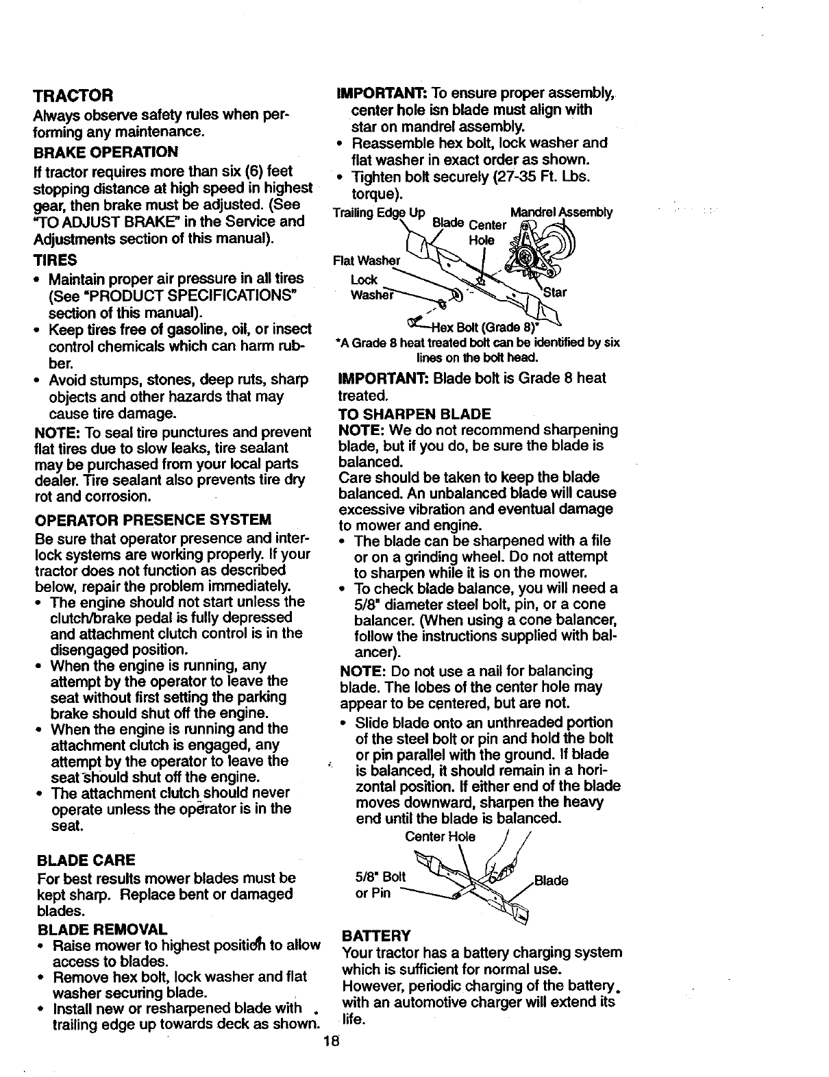
IMPORTANT: To ensure proper assembly,
center hole isn blade must align with
star on mandrel assembly.
•Reassemble hex bolt, lock washer and
flat washer in exact order as shown.
•Tighten bolt securely (27-35 Ft. Lbs.
torque).
TrailingEdgeUp Blade MandrelAssembly
BI/ Center _'_ F'_
F,atWasher I
"J'---Hex Bolt (Grade 8)* "_
*A Grade 8 heat treatedbeltcan be identifiedby six
linesonthe bolt heed.
IMPORTANT: Blade bolt is Grade 8 heat
treated.
TO SHARPEN BLADE
NOTE: We do not recommend sharpening
blade, but if you do, be sure the blade is
balanced.
Care should be taken to keep the blade
balanced. An unbalanced blade will cause
excessive vibration and eventual damage
to mower and engine.
•The blade can be sharpened with a file
or on a grinding wheel. Do not attempt
to sharpen while it is on the mower.
•To check blade balance, you will need a
5/8" diameter steel bolt, pin, or a cone
balancer. (When using a cone balancer,
follow the instructions supplied with bal-
ancer).
NOTE: Do not use a nail for balancing
blade. The lobes of the center hole may
appear to be centered, but are not.
•Slide blade onto an unthreaded portion
of the steel belt or pin and hold the bolt
or pin parallel with the ground. If blade
'is balanced, it should remain in a hori-
zontal position. If either end of the blade
moves downward, sharpen the heavy
end until the blade is balanced.
5/8 .Bolt _.,Blade
or Pin _._ ,_
BATTERY
Your tractor has a battery charging system
which is sufficient for normal use.
However, pedodic charging of the battery.
with an automotive charger will extend its
life.
18
•Keep battery and terminals clean.
•Keep battery bolts tight.
•Keep small vent holes open.
•Recharge at 6-10 amperes for 1 hour.
NOTE: The original equipment battery on
your tractor is maintenance free. Do not
attempt to open or remove caps or covers.
Adding or checking level of electrolyte is
not necessary.
TO CLEAN BATTERY AND TERMINALS
Corrosion and dirt on the battery and ter-
minals can cause the battery to "leak"
power.
•Remove terminal guard.
•Disconnect BLACK battery cable first
then RED battery cable and remove
battery from tractor.
•Rinse the battery with plain water and
vdry.
• Clean terminals and battery cable ends
with wire brush until bright.
•Coat terminals with grease or petroleum
jelly.
• Reinstall battery (See "REPLACING
BA-I-I-ERY" in the SERVICE AND
ADJUSTMENTS section of this manu-
al).
V-BELTS
Check V-belts for deterioration and wear
after 100 hours of operation and replace if
necessary. The belts are not adjustable.
Replace belts if they begin to slip from
wear.
TRANSAXLE COOLING
Keep transaxle free from build-up of dirt
and chaff which can restdct cooling.
ENGINE ..
LUBRICATION
Only use high quality detergent oil rated
with API service classification SF, SG or
SH. S_lect the oil's SAE viscosity grade
according to your expected operating tem-
perature.
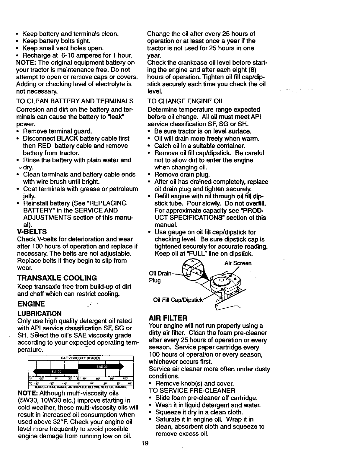
SAE VISCOSmf GRADES
NOTE: Although multi-viscosity oils
(5W30, 10W30 etc.) improve starting in
cold weather, these multi-viscosity oils will
result in increased oil consumption when
used above 32°F. Check your engine oil
level more frequently to avoid possible
engine damage from running low on oil.
Change the oil after every 25 hours of
operation or at least once a year if the
tractor is not used for 25 hours in one
year.
Check the crankcase oil level before start-
ing the engine and after each eight (8)
hours of operation. Tighten oil fill cap/dip-
stick securely each time you check the oil
level.
TO CHANGE ENGINE OIL
Determine temperature range expected
before oil change. All oil must meet API
service classification SF, SG or SH.
•Be sure tractor is on level surface.
•Oil will drain more freely when warm.
•Catch oil in a suitable container.
• Remove oil fill cap/dipstick. Be careful
not to allow dirt to enter the engine
when changing oil.
•Remove drain plug.
•After oil has drained completely, replace
oil drain plug and tighten securely.
•Refill engine with oil through oil fill dip-
stick tube. Pour slowly. Do not overfill.
For approximate capacity see "PROD-
UCT SPECIFICATIONS" section of this
manual.
•Use gauge on oil fill cap/dipstick for
checking level. Be sure dipstick cap is
tightened securely for accurate reading.
Keep oil at "FULL" line on dipstick.
Air Screen
Plug
Oil F
AIR FILTER
Your engine will not run propedy using a
dirty air filter. Clean the foam pre-cleaner
after every 25 hours of operation or every
season. Service paper cartridge every
100 hours of operation or every season,
whichever occurs first.
Service air cleaner more often under dusty
conditions.
•Remove knob(s) and cover.
TO SERVICE PRE-CLEANER
• Slide foam pre-cleaner off cartridge.
•Wash it in liquid detergent and water.
•Squeeze it dry in a clean cloth.
•Saturate it in engine oil. Wrap it in
clean, absorbent cloth and squeeze to
remove excess oil.
19
•If very dirty or damaged, replace pre-
cleaner.
•Reinstall pre-cleaner over cartridge.
•Reinstall cover and secure with knob(s).
TO SERVICE CARTRIDGE
•Remove wing nuts and cartridge plate.
•Carefully remove cartridge to prevent
debris from entering carburetor.
•Clean cartridge by tapping gently on flat _
surface. If very dirty or damaged,
replace cartridge.
•Reinstall cartridge plate, wing nuts, pre-
cleaner, Cover and secure with knob(s).
IMPOIRTAN'I': Petroleum solvents, such
as kerosene, are not to be used to clean
the cartridge. They may cause deteriora-
tion of the cartridge. Do not oil cartridge.
Do not use pressurized air to clean or dry
cartridge.
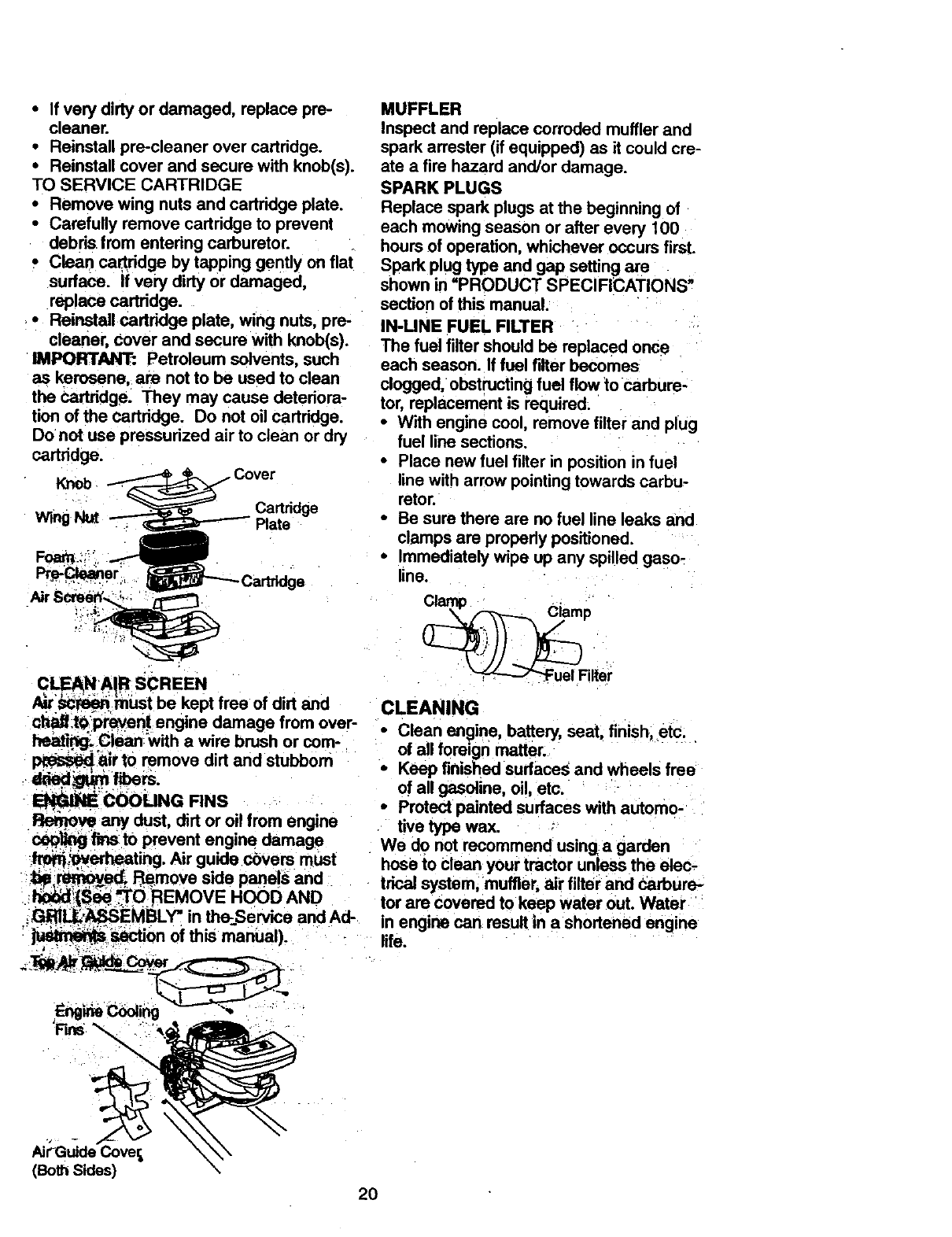
Knob
Cartridge
Wing Plate
CLEAN AIR SCREEN
/__:_ _niJst be kept free of dirt and
cbaff.t_preyen.t engine damage from over-
_. Clean;_with a wire brush or com-
-'air to remove dirt and stubborn
-_" COOLING RNS
Ret_ve any dust, dirt or oil from engine
_)i_fi_ t0 prevent engine damage
_erheating. Air guide covers must
t_ R_move side panels and
_(S_ _O REMOVE HOOD AND
._G_,LI_EMBLY =in th_service and Ad-
: __on of this manUal).
MUFFLER
Inspect and replace corroded muffler and
spark arrester (if equipped) as it could cre-
ate a fire hazard and/or damage.
SPARK PLUGS
Replace spark plugs at the beginning of
each mowing season or after every 100
hours of operation, whichever occurs first.
Spark plug type and gap setting are
shown in =PRODUCT SPECIFICATIONS"
section of this manual.
IN-UNE FUEL FILTER
The fuel filter should be replaced once
each season. If fuel filter becomes
clogged, obstructing fuel flow to carbure-
tor, replacement is required:
•With engine cool, remove filter and plug
fuel line sections•
•Place new fuel filter in position in fuel
line with arrow pointing towards carbu-
retor.
•Be sure there are no fuel line leaks and
clamps are propedy positioned.
•Immediately wipe up any spille d gaso-
line.
P
_iel Filter
CLEANING
iClean engine battery, seat, finish etc.
of all foreign matter. ....
Keep finished surfaces and wheels free
of all gasoline, oil, etc.
•Protectpainted surfaces with automo-
tive type wax.
We do not recommend usinga garden
hose to clean your tractor unless the elec,
trical system,muffler, air filter and Carbure-
tor are covered to keep water Out. Water
In engine can result in a shortened engine
life.
AirGuide Cover,
(Both Sides)
20
_CAUTION: Before performing any service or adjustments:
•Depress clutch/brake pedal fully and set parking brake,
•Place gearshift lever in neutral (N) position,
•Place attachment clutch in "DISENGAGED" position.
•Turn ignition key =OFP and remove key.
•Make sure the blades and all moving parts have completely stopped.
•Disconnect spark plug wire from spark plug and place wire where it cannot come
in contact with plug.
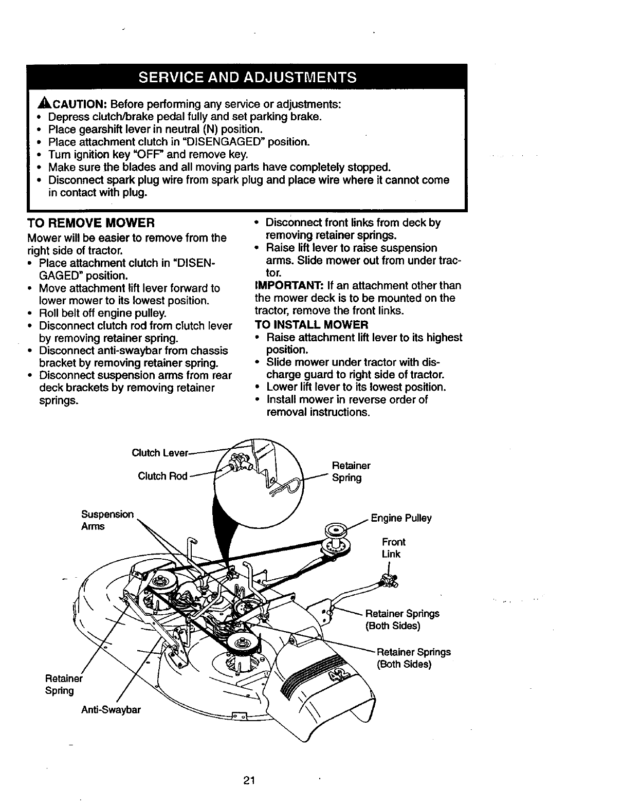
TO REMOVE MOWER
Mower will be easier to remove from the
right side of tractor.
•Place attachment clutch in =DISEN-
GAGED" position.
•Move attachment lift lever forward to
lower mower to its lowest position.
• Roll belt off engine pulley.
•Disconnect clutch rod from clutch lever
by removing retainer spdng.
•Disconnect anti-swaybar from chassis
bracket by removing retainer spring.
•Disconnect suspension arms from rear
deck brackets by removing retainer
springs.
•Disconnect front links from deck by
removing retainer spdngs.
•Raise lift lever to raise suspension
arms. Slide mower out from under trac-
tor.
IMPORTANT: If an attachment other than
the mower deck is to be mounted on the
tractor, remove the front links.
TO INSTALL MOWER
•Raise attachment lift lever to its highest
position.
•Slide mower under tractor with dis-
charge guard to dght side of tractor.
•Lower lift lever to its lowest position.
•Install mower in reverse order of
removal instructions.
Clutch
Clutch Retainer
Spring
Suspension
Arms
Front
Link
(Both Sides)
Retainer
Spring
Anti-Swaybar
(Both Sides)
21
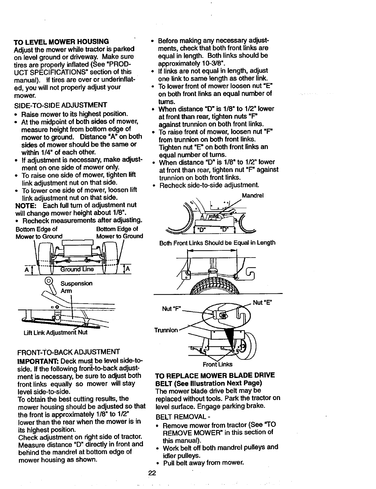
TOLEVELMOWERHOUSING
Adjust the mower while tractor is parked
on level ground or driveway. Make sure
tires are properly inflated (See =PROD-
UCT SPECIFICATIONS" section of this
manual). If tires are over or underinflat-
ed, you will not properly adjust your
mower.
SIDE-TO-SIDE ADJUSTMENT
•Raise mower to its highest position.
•At the midpoint of both sides of mower,
measure height from bottom edge of
mower to ground. Distance =A" on both
sides of mower should be the same or
within 1/4" of each other.
•If adjustment is necessary, make adjust-
ment on one side of mower only.
•To raise one side of mower, tighten lift
link adjustment nut on that side.
•To lower one side of mower, loosen lift
link adjustment nut on that side.
NOTE: Each full turn of adjustment nut
will change mower height about 1/8".
•Recheck measurements after adjusting.
Bottom Edge of Bottom Edge of
Mower to Ground Mower to Ground
_o_ Suspensi°n
FRONT-TO-BACK ADJUSTMENT
IMPORTANT: Deck must be level side-to-
side. If the following front-to-back adjust-
ment is necessary, be sure to adjust both
front links equally so mower will stay
level side-to-side.
To obtain the best cutting results, the
mower housing should be adjusted so that
the front is approximately 1/8" to 1/2"
lower than the rear when the mower is in
its highest position.
Check adjustment on right side of tractor.
Measure distance "D" directly in front and
behind the mandrel at bottom edge of
mower housing as shown.
•Before making any necessary adjust-
ments, check that both front links are
equal in length. Both links should be
approximately 10-3/8".
•If links are not equal in length, adjust
one link to same length as other link.
•To lower front of mower loosen nut "E"
on both front links an equal number of
turns.
• When distance "D" is 1/8" to 1/2" lower
at front than rear, tighten nuts =P
against trunnion on both front links.
•To raise front of mower, loosen nut =P
from trunnion on both front links.
Tighten nut =E" on both front links an
equal number of turns.
•When distance "D" is 1/8" to 1/2" lower
at front than rear, tighten nut =P against
trunnion on both front links.
•Recheck side-to-side adjustment.
Mandrel
qo oo
Both FrontLinks Should be Equal in Length
TmnnionNUt"P..____ _ut "E"
Front Links
TO REPLACE MOWER BLADE DRIVE
BELT (See Illustration Next Page)
The mower blade drive belt may be
replaced without tools. Park the tractor on
level surlace. Engage parking brake.
BELT REMOVAL -
•Remove mower from tractor (See =TO
REMOVE MOWER" in this section of
this manual).
•Work belt off both mandrel pulleys and
idler pulleys.
•Pull belt away from mower.
22
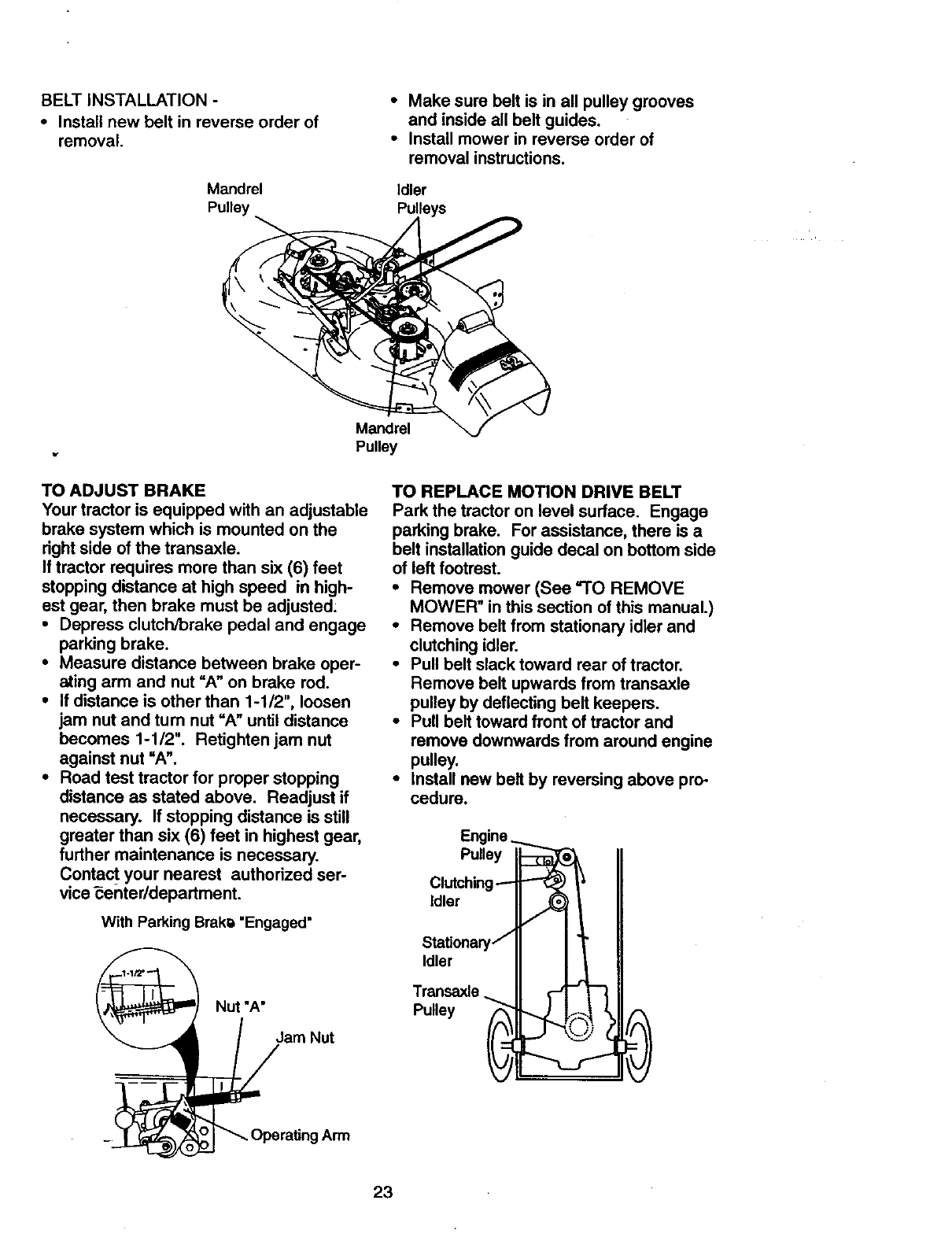
BELT INSTALLATION -
• Install new belt in reverse order of
removal
Mandrel
Pulley
•Make sure belt is in all pulley grooves
and inside all bolt guides.
• Install mower in reverse order of
removal instructions.
Idler
Pulleys
Mandrel
Pulley
TO ADJUST BRAKE
Your tractor is equipped with an adjustable
brake system which is mounted on the
right side of the transaxle.
If tractor requires more than six (6) feet
stopping distance at high speed in high-
est gear, then brake must be adjusted:
•Depress clutch/brake pedal and engage
parking brake.
• Measure distance between brake oper-
ating arm and nut "A" on brake rod.
•If distance is other than 1-1/2", loosen
jam nut and tum nut "A" until distance
becomes 1-1/2". Retightenjam nut
against nut "A".
• Road test tractor for proper stopping
distance as stated above. Readjust if
necessary. If stopping distance is still
greater than six (6) feet in highest gear,
further maintenance is necessary.
Conta_ your nearest authorized ser-
vice _enter/department.
With Parking Brak_ "Engaged"
Nut "A"
/am Nut
oO_Operating Arm
TO REPLACE MOTION DRIVE BELT
Park the tractor on level surface. Engage
parking brake. For assistance, there is a
belt installation guide decal on bottom side
of left footrest.
•Remove mower (See "TO REMOVE
MOWER" in this section of this manual.)
•Remove belt from stationary idler and
clutching idler.
•Pull belt slack toward rear of tractor.
Remove belt upwards from transaxle
pulley by deflecting belt keepers.
•Putt belt toward front of tractor and
remove downwards from around engine
pulley,
•Install new belt by reversing above pro-
cedure.
Engine
Pulley ._
Clutching-_
Idler _=
St.ationsry7
Idler
Transaxle.
Pulley i
23
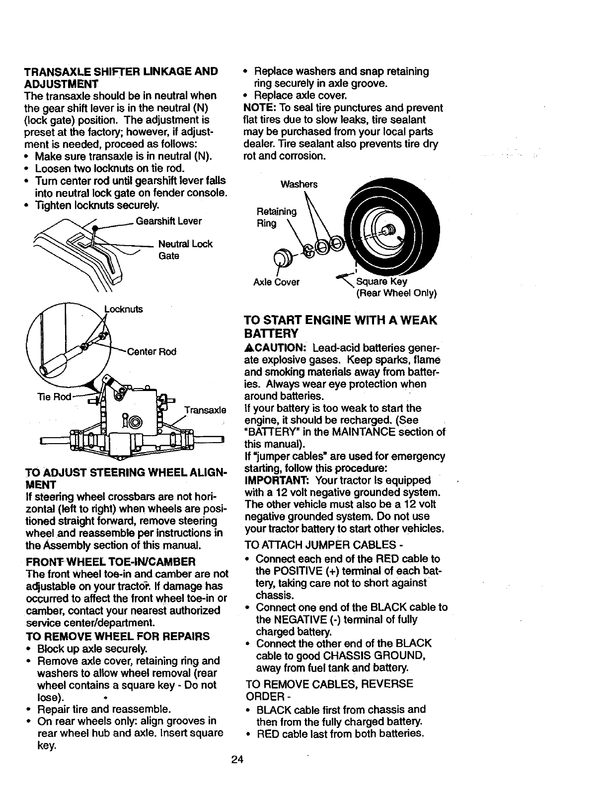
TRANSAXLE SHIFTER LINKAGE AND
ADJUSTMENT
The transaxle should be in neutral when
the gear shift lever is in the neutral (N)
(lock gate) position. The adjustment is
preset at the factory; however, if adjust-
ment is needed, proceed as follows:
•Make sure transaxle is in neutral (N).
•Loosen two Iocknuts on tie red.
•Tum center rod until gearshift lever falls
into neutral lock gate on fender console.
•Tighten Iocknuts securely.
Gearshift Lever
Neutral Lock
__ Gate
Locknuts
Transaxle
TO ADJUST STEERING WHEEL ALIGN-
MENT
If steering wheel crossbars are not hori-
zontal (left to right) when wheels are posi-
tioned straight forward, remove steering
wheel and reassemble per instructions in
the Assembly section of this manual.
FRONTWHEEL TOE-IN/CAMBER
The front wheel toe-in and camber are not
adjustable on your tractor. If damage has
occurred to affect the front wheel toe-in or
camber, contact your nearest authorized
service center/department.
TO REMOVE WHEEL FOR REPAIRS
•Block up axle securely.
•Remove axle cover, retaining ring and
washers to allow wheel removal (rear
wheel contains a square key - Do not
lose).
•Repair tire and reassemble.
•On rear wheels only: align grooves in
rear wheel hub and axle. Insert square
key.
•Replace washers and snap retaining
ring securely in axle groove.
•Replace axle cover.
NOTE: To seal tire punctures and prevent
flat tires due to slow leaks, tire sealant
may be purchased from your local parts
dealer. Tire sealant also prevents tire dry
rot and corrosion.
Washers
Retaining
Ring
Axle Cover '_
(Rear Wheel Only)
TO START ENGINE WITH A WEAK
BATTERY
_CAUTION: Lead-acid batteries gener-
ate explosive gases. Keep sparks, flame
and smoking materials away from batter-
ies. Always wear eye protection when
around batteries.
If your battery is too weak to start the
engine, it should be recharged. (See
"BATTERY" in the MAINTANCE section of
this manual).
If "jumper cables" are used for emergency
starting, follow this procedure:
IMPORTANT: Your tractor Is equipped
with a 12 volt negative grounded system.
The other vehicle must also be a 12 volt
negative grounded system. Do not use
your tractor battery to start other vehicles.
TO ATTACH JUMPER CABLES -
•Connect each end of the RED cable to
the POSITIVE (+) terminal of each bat-
tery, taking care not to short against
chassis.
•Connect one end of the BLACK cable to
the NEGATIVE (-) terminal of fully
charged battery
• Connect the other end of the BLACK
cable to good CHASSIS GROUND,
away from fuel tank and battery
TO REMOVE CABLES, REVERSE
ORDER
• BLACK cable first from chassis and
then from the fully charged battery
• RED cable last from both batteries
24

"Pos=t=ve"(+) Negative ()
REPLACING BATTERY
_CAUTION: Do not short battery termi-
nals by allowing a wrench or any other
object to contact both terminals at the
same time. Before connecting battery,
remove metal bracelets, wristwatch
bands,rings,etc.
Positive terminal must be connected first
to prevent sparking from accidental
grounding.
• Lift hood to raised position.
• Remove terminal guard.
•Disconnect BLACK battery cable then
RED battery cable and carefully remove
battery from tractor.
•Install new battery with terminals in
same position as old battery.
• Reinstall terminal guard.
•First connect RED battery cable to posi-
tive (+) battery terminal with hex bolt
and keps nut as shown. Tighten
securely.
•Connect BLACK grounding cable to
negative (-) battery terminal with
remaining hex bolt and keps nut.
Tighten securely.
•Close terminal access doom.
• Close hood.
Terminal
Access ._';_.;::{"
Hex
Red)
Cable
Negative
Cable
TO REPLACE HEADLIGHT BULB
•Raise hood.
•Pull bulb holder out of the hole in the
backside of the grill.
•Replace bulb in holder and push bulb
holder securely back into the hole in the
backside of the grill.
•Close hood.
INTERLOCKS AND RELAYS
Loose or damaged wiring may cause your
tractor t6 run poorly, stop running, or pre-
vent it from starting.
•Check wiring. See electrical widng dia-
gram in the Repair Parts section.
TO REPLACE FUSE
Replace with 30 amp automotive-type
plug-in fuse. The fuse holder is located
behind the dash.
TO REMOVE HOOD AND GRILL
ASSEMBLY
•Raise hood.
•Unsnap headlight wire connector.
•Stand in front of tractor. Grasp hood at
sides, tilt toward engine and lift off of
tractor.
•To replace, reverse above procedures.
Headlight
Wire Connector
ENGINE
Maintenance, repair, or replacement of the
emission control devices and systems,
which are being done at the customers
expense, may be performed by any non-
road engine repair establishment or indi-
vidual. Warranty repairs must be per-
formed by an authorized engine manufac-
turer's service outlet.
TO ADJUST THROTTLE CONTROL
CABLE
The throttle control has been preset at the
factory and adjustment should not be nec-
essary. Check adjustment as described
below before loosening cable. If adjust-
ment is necessary, proceed as follows:
•With engine not running, move throttle
control lever to fast position;
•Check that swivel is against side of
quarter circle. If it is not, loosen cable
clamp screw and pull cable back until
swivel is against quarter circle. Tighten
cable clamp screw securely.
TO ADJUST CHOKE CONTROL
The choke control has been preset at the
factory and adjustment should not be nec-
essary. Check adjustment as described
below before loosening cable. If adjust-
ment is necessary, proceed as follows:
•With engine not running, move choke
control (located on dash panel) to full
choke position.
25
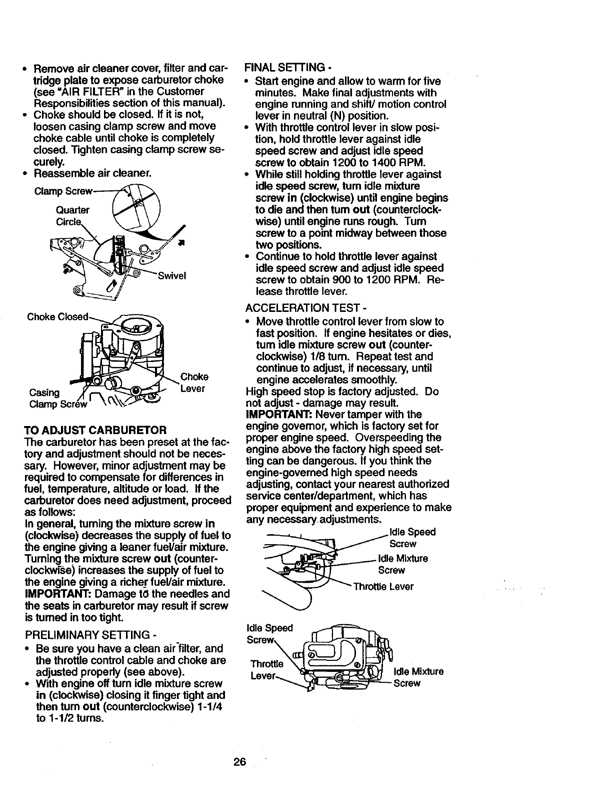
• Remove air cleaner cover, filter and car-
tridge plate to expose carburetor choke
(see =AIR FILTER" in the Customer
Responsibilities section of this manual).
•Choke should be closed. If it is not,
loosen casing clamp screw and move
choke cable until choke is completely
closed. Tighten casing clamp screw se-
curely.
•Reassemble air cleaner.
Clamp Screw-_F_ _
Quarter _F,_ \ )
Choke
Casing
Claml:
Choke
TO ADJUST CARBURETOR
The carburetor has been preset at the fac-
tory and adjustment should not be neces-
sary. However, minor adjustment may be
required to compensate for differences in
fuel, temperature, altitude or load. If the
carburetor does need adjustment, proceed
as follows:
In general, turning the mixture screw in
(clockwise) decreases the supply of fuel to
the engine giving a leaner fuel/air mixture.
Tuming the mixture screw out (counter-
clockwiSe) increases the supply of fuel to
the engine giving a richer fuel/air mixture.
IMPORTANT: Damage to the needles and
the seats in carburetor may result if screw
is tumed in too tight.
PRELIMINARY SETTING -
•Be sure you have a clean airfilter, and
the throttle control cable and choke are
adjusted properly (see above).
•With engine off turn idle mixture screw
in (clockwise) closing it finger tight and
then turn out (counterclockwise) 1-1/4
to 1-1/2 turns.
FINAL SE'I-I'ING -
•Stad engine and allow to warm for five
minutes. Make final adjustments with
engine running and shift/motion control
lever in neutral (N) position.
• With throttle control lever in slow posi-
tion, hold throttle lever against idle
speed screw and adjust idle speed
screw to obtain 1200 to 1400 RPM.
•While still holding throttle lever against
idle speed screw, tum idle mixture
screw in (clockwise) until engine begins
to die and then tum out (counterclock-
wise) until engine runs rough. Turn
screw to a point midway between those
two positions.
•Continue to hold throttle lever against
idle speed screw and adjust idle speed
screw to obtain 900 to 1200 RPM. Re-
lease throttle lever.
ACCELERATION TEST -
•Move throttle control lever from slow to
fast position. If engine hesitates or dies,
tum idle mixture screw out (counter°
clockwise) 118 tum. Repeat test and
continue to adjust, if necessary, until
engine accelerates smoothly.
High speed stop is factory adjusted. Do
not adjust - damage may result.
IMPORTANT: Never tamper with the
engine govemor, which is factory set for
proper engine speed. Overspeeding the
engine above the factory high speed set-
ting can be dangerous. If you think the
engine-governed high speed needs
adjusting, contact your nearest authorized
service centerldepadment, which has
proper equipment and experience to make
any necessaryadjustments.
ldle Speed
Screw
eMixture
rew
Lever
Idle Speed
Screw
Lever_ Idle Mixture
26
Immediately prepare your tractor for stor-
age at the end of the season or if the trac-
tor will not be used for 30 days or more.
_CAUTION: Never store the tractor with
gasoline in the tank inside a building
where fumes may reach an open flame or
spark. Allow the engine to cool before stor-
ing in any enclosure.
TRACTOR
Remove mower from tractor for winter
storage. This will allow you to clean it thor-
oughly. Remove all dirt, grease, leaves,
etc. Store in a clean, dry area.
•Clean entire tractor (See "CLEANING" in
the Maintenance section of this manual).
•,Inspect and replace belts, if necessary
(See belt replacement instructions in the
Service and Adjustments section of this
manual).
•Lubricate as shown in the Maintenance
section of this manual.
•Be sure that all nuts, bolts and screws
are securely fastened. Inspect moving
parts for damage, breakage and wear.
Replace if necessary.
• Touch up all rusted or chipped paint sur-
faces; sand lightly before painting.
BATTERY
• Fully charge the battery for storage.
• After a period of time in storage, battery
may require recharging.
• To help prevent corrosion and power
leakage during long periods of storage,
battery cables should be disconnected
and battery cleaned thoroughly (see "TO
CLEAN BATTERY AND TERMINALS" in
the Maintenance section of this manual).
•After-cleaning, leave cables disconnect-
ed and place cables where they cannot
come in contact with 15attery terminals.
•If battery is removed from tractor for
storage, do not store battery directly on
concrete or damp surfaces.
ENGINE
FUEL SYSTEM
IMPORTANT: it is important to prevent
gum deposits from forming in essential fuel
system parts such as carburetor, fuel filter,
fuel hose, or tank during storage. Also,
experience indicates that alcohol blended
fuels (called gasohol or using ethanol or
methanol) can attract moisture which
leads to separation and formation of acids
during storage. Acidic gas can damage the
fuel system of an engine while in storage.
•Drain the fuel tank.
•Start the engine and let it run until the
fuel lines and carburetor are empty.
•Never use engine or carburetor cleaner
products in the fuel tank or permanent
damage may occur.
•Use fresh fuel next season.
NOTE: Fuel stabilizer is an acceptable
altemative in minimizing the formation of
fuel gum deposits during storage. Add sta-
bilizer to gasoline in fuel tank or storage
container. Always follow the mix ratio
found on stabilizer container. Run engine
at least 10 minutes after adding stabilizer
to allow the stabilizer to reach the carbure-
tor. Do not drain the gas tank and carbure-
tor if using fuel stabilizer.
ENGINE OIL
Drain oil (with engine warm) and replace
with clean engine oil. (See "ENGINE" in
the Maintenance section of this manual).
CYLINDER(S)
•Remove spark plug(s).
•Pour one ounce of oil through spark
plug hole(s) into cylinder(s).
•Tum ignition key to "START" position for
afew seconds to distribute oil.
•Replace with new spark plug(s).
OTHER
•Do not store gasoline from one season
to another,
•Replace your gasoline can if it starts to
rust. Rust and/or dirt in your gasoline
will cause problems.
•If possible, store your tractor indoors
and cover it to give protection from dust
and dirt.
•Cover your tractor with a suitable pro-
tective cover that does not retain mois-
ture. Do not use plastic. Plastic cannot
breathe, which allows condensation to
form and cause your tractor to rust.
IMPORTANT: Never cover tractor while
engine and exhaust areas are still warm.
27
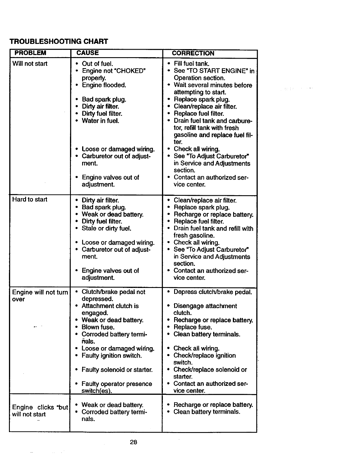
TROUBLESHOOTING CHART
PROBLEM
Will not start
Hard to start
Engine will not turn
over
Engine clicks "but
will not start
CAUSE CORRECTION
• Out of fuel.
•Engine not =CHOKED"
properly.
• Engine flooded.
• Bad spark plug.
•Dirty air filter. •
• Dirty fuel filter.
•Water in fuel. •
•Loose or damaged wiring. •
•Carburetor out of adjust- •
ment.
•Engine valves out of
adjustment.
• Dirty air filter. •
• Bad spark plug.
• Weak or dead battery. •
•Dirty fuel filter. •
•Stale or dirty fuel,
•Loose or damaged wiring. •
•Carburetor out of adjust- •
ment,
•Engine valves out of •
adjustment.
•Clutch/brake pedal not
depressed.
•Attachment clutch is •
engaged.
•Weak or dead battery. •
•Blown fuse. •
•Corroded battery termi- •
rrals.
•Loose or damaged wiring. •
•Faulty ignition switch. •
• Faulty solenoid or starter. •
•Faulty operator presence •
switch(es).
• Weak or dead battery. •
•Corroded battery termi- •
nals.
Fill fuel tank.
See =TO START ENGINE" in
Operation section.
Wait several minutes before
attempting to start.
Replace spark plug.
Clean/replace air filter.
Replace fuel filter.
Drain fuel tank and carbure-
tor, refill tank with fresh
gasoline and replace fuel fil-
ter.
Check all wiring.
See =ToAdjust Carburetor"
in Service and Adjustments
section.
Contact an authorized ser-
vice center.
Clean/replace air filter.
Replace spark plug.
Recharge or replace battery.
Replace fuel filter.
Drain fuel tank and refill with
fresh gasoline.
Check all wiring.
See "To Adjust Carburetor"
in Service and Adjustments
section.
Contact an authorized ser-
vice center.
Depress clutch/brake pedal.
Disengage attachment
clutch.
Recharge or replace battery,
Replace fuse.
Clean battery terminals.
Check all wiring.
Check/replace ignition
switch.
Check/replace solenoid or
starter.
Contact an authorized ser-
vice center.
Recharge or replace battery.
Clean battery terminals.
28
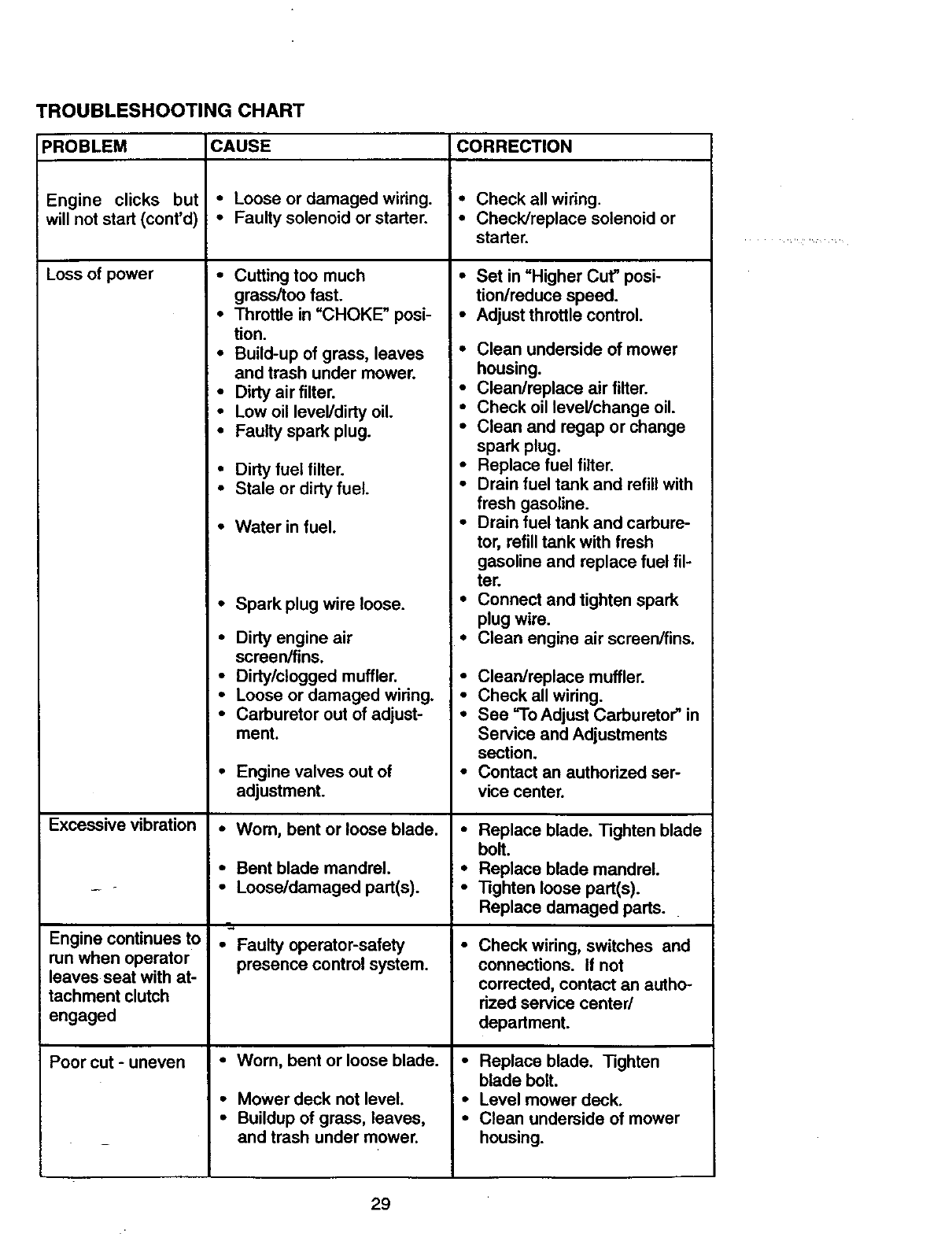
TROUBLESHOOTING CHART
CAUSE
•Loose or damaged wiring.
• Faulty solenoid or starter.
• Dirty fuel filter.
• Stale or dirty fuel.
PROBLEM
Engine clicks but
will not start (cont'd)
Loss of power
Excessive vibration
Engine continues to
run when operator
leaves seat with at-
tachment clutch
engaged
Poor cut - uneven
•Water in fuel.
• Spark plug wire loose.
• Faulty operator-safety
presence control system.
•Worn, bent or loose blade.
•Mower deck not level.
•Buildup of grass, leaves,
and trash under mower.
CORRECTION
• Check all wiring.
• Check/replace solenoid or
starter.
Cutting too much •
grass/too fast.
Throttle in "CHOKE" posi- •
tion.
Build-up of grass, leaves •
and trash under mower.
Dirty air filter. •
Low oil leveVdirty oil. "
Faulty spark plug. •
Dirty engine air •
screen/fins.
Dirty/clogged muffler. •
Loose or damaged wiring. •
Carburetor out of adjust- •
ment.
Engine valves out of
adjustment.
Worn, bent or loose blade. •
Bent blade mandrel. •
Loose/damaged part(s). •
Set in "Higher Cut" posi-
tion/reduce speed.
Adjust throttle control.
Clean underside of mower
housing.
Clean/replace air filter.
Check oil level/change oil.
Clean and regap or change
spark plug.
Replace fuel filter.
Drain fuel tank and refill with
fresh gasoline.
Drain fuel tank and carbure-
tor, refill tank with fresh
gasoline and replace fuel fil-
ter.
Connect and tighten spark
plug wire.
Clean engine air screen/fins.
Clean/replace muffler.
Check all wiring.
See "To Adjust Carburetor" in
Service and Adjustments
section.
•Contact an authorized ser-
vice center.
Replace blade. Tighten blade
bolt.
Replace blade mandrel.
Tighten loose part(s).
Replace damaged parts.
Check wiring, switches and
connections. If not
corrected, contact an autho-
rized service center/
department.
Replace blade. Tighten
blade bolt.
Level mower deck.
Clean underside of mower
housing.
29
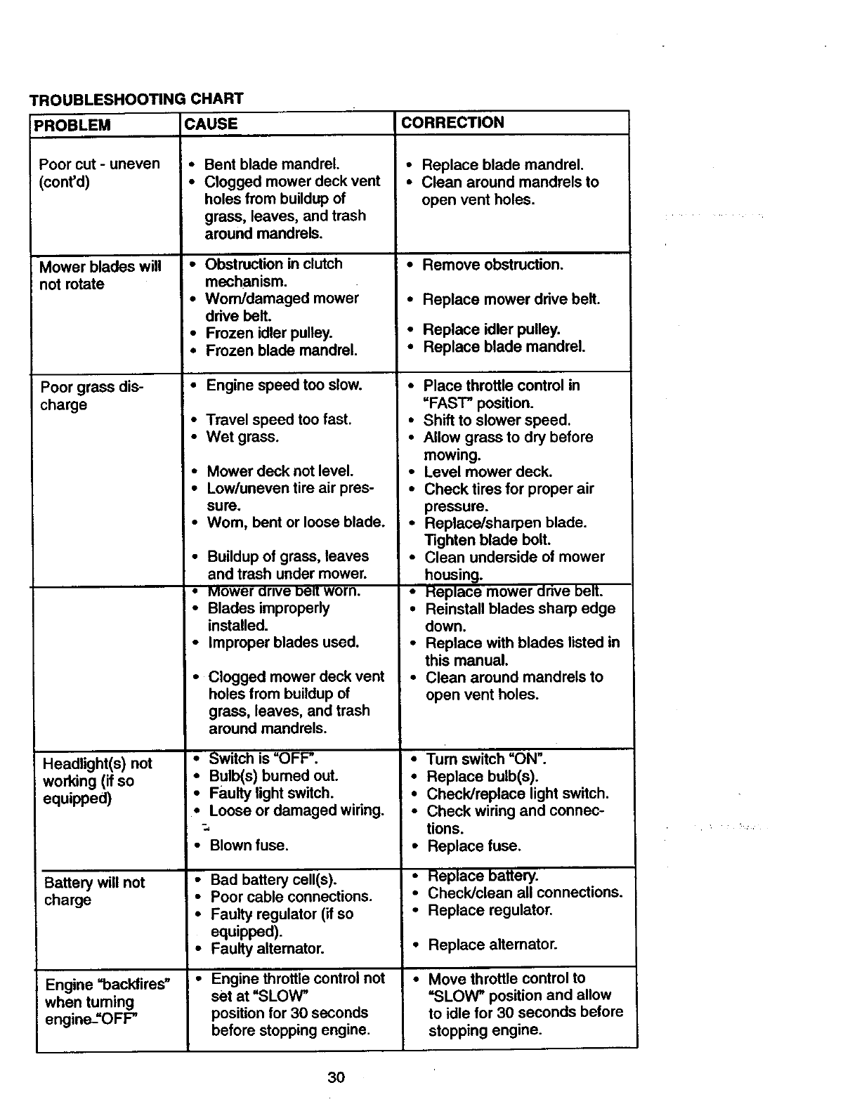
TROUBLESHOOTING:HART
PROBLEM CAUSE CORRECTION
Poorcut - uneven
(cant'd)
Mower blades will
not rotate
Poor grass dis-
charge
Headlight(s) not
working (if so
equipped)
Battery will not
charge
Engine =backfires"
when tuming
engine#OFP
•Bent blade mandrel.
•Clogged mower deck vent
holes from buildup of
grass, leaves, and trash
around mandrels.
•Obstruction in clutch
mechanism.
•Worn/damaged mower
drive belt.
•Frozen idler pulley.
•Frozen blade mandrel.
•Engine speed too slow.
•Travel speed too fast.
• Wet grass.
•Mower deck not level.
•Low/uneven tire air pres-
sure.
•Wom, bent or loose blade.
•Buildup of grass, leaves
and trash under mower.
•Mower arlve Del! worn.
•Blades improperly
installed.
•Improper blades used.
•Clogged mower deck vent
holes from buildup of
grass, leaves, and trash
around mandrels.
•Switch is =OFP.
=• Bulb(s) burned out.
•Faulty light switch.
•Loose or damaged wiring.
•Blown fuss.
•Bad battery cell(s).
•Poor cable connections.
•Faulty regulator (if so
equipped).
•Faulty alternator.
•Engine throttle control not
Set at "SLOW"
position for 30 seconds
before stopping engine.
•Replace blade mandrel.
•Clean around mandrels to
open vent holes.
•Remove obstruction.
•Replace mower drive belt.
•Replace idler pulley.
•Replace blade mandrel.
•Place throttle control in
=FAST" position.
•Shift to slower speed.
•Allow grass to dry before
mowing.
•Level mower deck.
•Check tires for proper air
pressure.
•Replace/sharpen blade.
Tighten blade bolt.
•Clean underside of mower
housing.
•Heplace mower dnve belt.
•Reinstall blades sharp edge
down.
•Replace with blades listed in
this manual.
•Clean around mandrels to
open vent holes.
•Tum switch =ON".
•Replace bulb(s).
•Check/replace light switch.
•Check wiring and connec-
tions.
•Replace fuse.
•Replace battery.
•Check/clean all connections.
•Replace regulator.
•Replace alternator.
•Move throttle control to
=SLOW" position and allow
to idle for 30 seconds before
stopping engine.
30
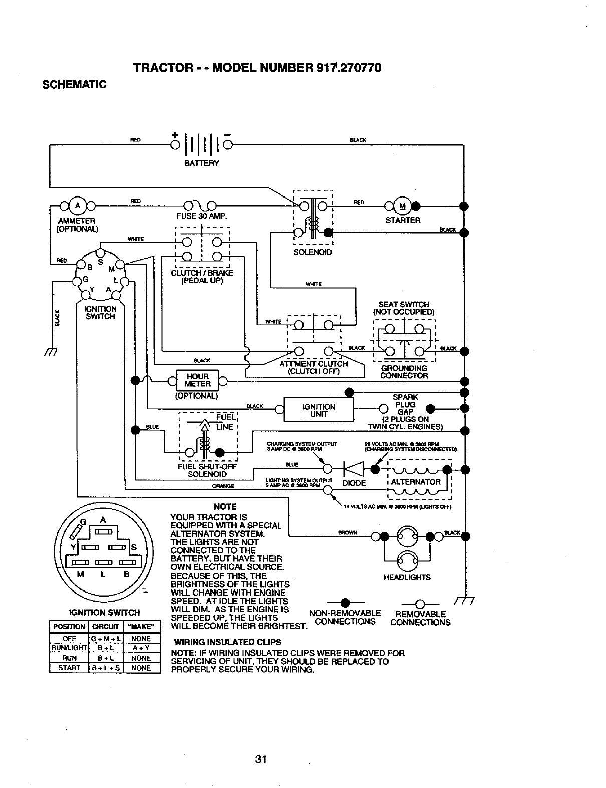
SCHEMATIC
TRACTOR - - MODEL NUMBER 917.270770
BA'R'ERY
RED
AMMETER
(OPTIONAL)
WHITE
IGNITION
SWITCH
IGNITION SWITCH
FUSE 30 AMP.
',© : O_,'--
• ........ J
CLUTCH /BRAKE
(PEDAL UP)
BLACK
(OPTIONAL)
mACK
I I
I RED
I WHITE
I SEAT SWITCH
-- -_-- --, '1 (_T_^^---__c____,_=__),
I_ I-I I-
( _ ....... _......... ,
ATPMENTCLUTCH _ _-_-_.-_._,_.._-'
(CLUTC.OF_ i g_g_
A
vSPARK
IGNITION GAP _-
•=UNIT
tFUELi J (2 PLUGS ON
m_uE :LINE :"nN]N CYL ENGINES) ,
I_ CHAI_N(S SYSTEM_L_ VOLT8 ACMK e_100 RPM
FUELSN.T_; =,- __ -,,
SOLENOID _J _ 1It : "_.J_J_J_,-IIW-_
=UGHTING SYSTEMOUtPt/'r I
SAUp^CO_00_IT_ DIOOI= ;.ALTERNATOR I'I
THE LIGHTS ARE NOT _(_P_ J_P_-_
CONNECTED TO THE
BA3TERY, BUT HAVE THEIR
OWN ELECTRICAL SOURCE.
BECAUSE OF THIS, THE HEADLIGHTS
BRIGHTNESS OF THE LIGHTS
WILL CHANGE WITH ENGINE
SPEED. AT IDLE THE LIGHTS
WILL DIM. ASTHE ENGINE IS
POSITION CIRCUIT "MAKE"
SPEEDED UP, THE LIGHTS NON-REMOVABLE REMOVABLE
WILL BECOME THEIR BRIGHTEST. CONNECTIONS CONNECTIONS
OFF G+M+L
RUN/LIGHT B + L
RUN B+L
START B+L+S
NONE WIRING INSULATED CLIPS
A÷Y NOTE: IF WIRING INSULATED CLIPS WERE REMOVED FOR
NONE SERVICING OF UNIT, THEY SHOULD BE REPLACED TO
NONE PROPERLY SECURE YOUR WIRING.
31
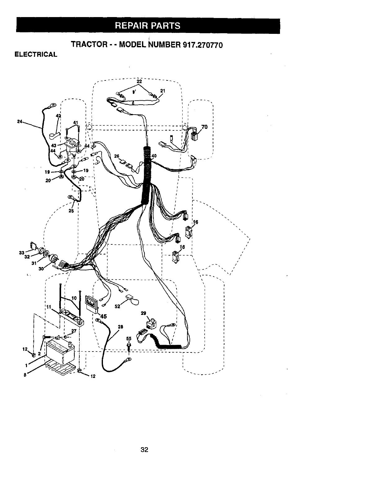
TRACTOR - - MODEL NUMBER 917.270770
ELECTRICAL
I
I
24 41
26
?
I
I
i
J
/I
/
/
/'
32
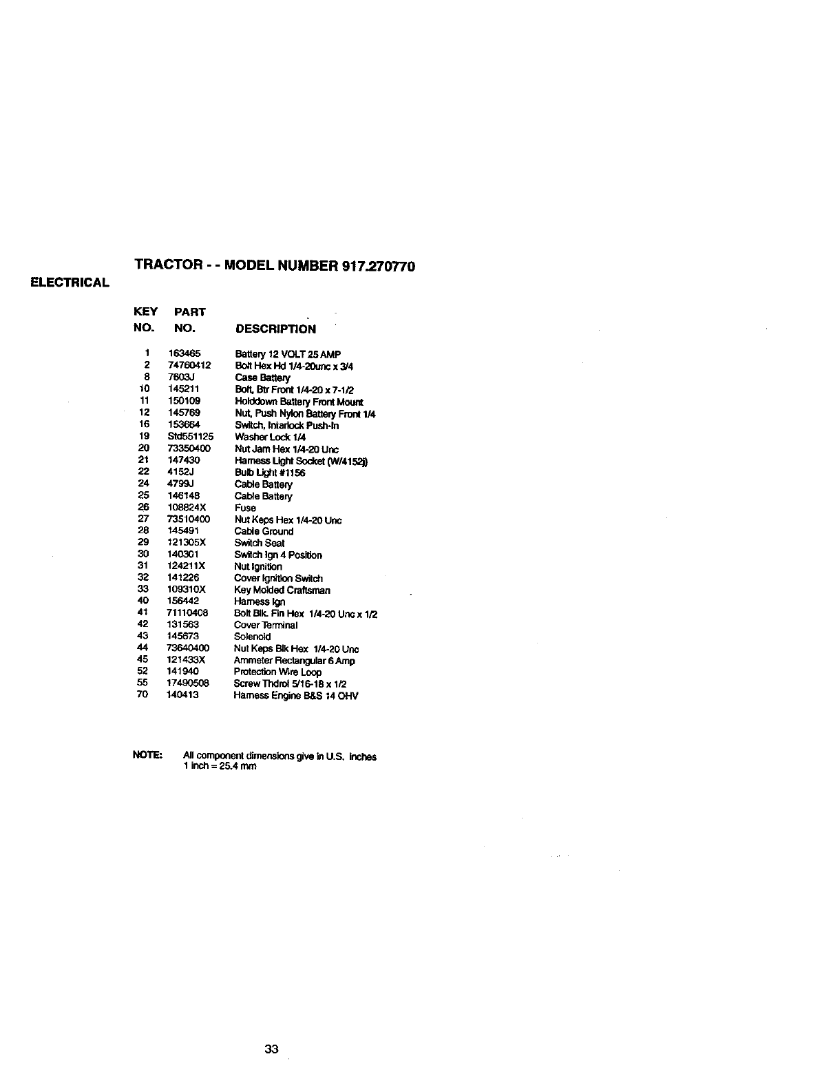
ELECTRICAL
TRACTOR - - MODEL NUMBER 917.270770
KEY PART
NO. NO. DESCRIPTION
1 163465 Batter/12 VOLT 25 AMP
2 74760412 B_t Hex Hd 1/4-20unc x 3/4
8 7603J Case Batter/
10 145211 Bott, Btr Front 1/4-20 x 7-1/2
11 150109 Holddown Battery Front Mou_
12 145769 Nut, Push Nyk_ Batter/Fro_ 1/4
16 1_664 Sw;tch, Intarinck Pus_ln
19 Sid551125 Washer Lode 1/4
20 73350400 Nut Jam Hex 1/4-20 Uric
21 147430 Harness Ught Sod_et 0N/4152_
22 4152J Bub Light #1156
24 4799J Cable Batten/
25 146148 Cable Batter/
26 108824X Fuse
27 73510400 Nut Keps He)( 1/4-20 Unc
28 145491 Cable Ground
29 121305X Switch Seat
30 140301 Switch Ign 4 Posi_on
31 124211X Nut Ignition
32 141226 Cover Igni0on Switch
33 109310X Key Molded Craltsman
40 156442 Harness Ign
41 71110408 Bolt BIk. Fin Hex 1/4-20 Unc x 1/2
42 131563 Cover Terminal
43 145673 Solenoid
44 73640400 Nut Keps B_ Hex 1/4-20 Unc
45 121433X Ammeter Rectangular 6 Amp
52 141940 Protection Wire Loop
55 17490508 Screw Thdrol 5/16-18 x 1/2
70 140413 Harness Engine B&S 14 OHV
NOTE: All component dirnerksk_ give in U.S. inches
1 inch = 25.4 mm
33
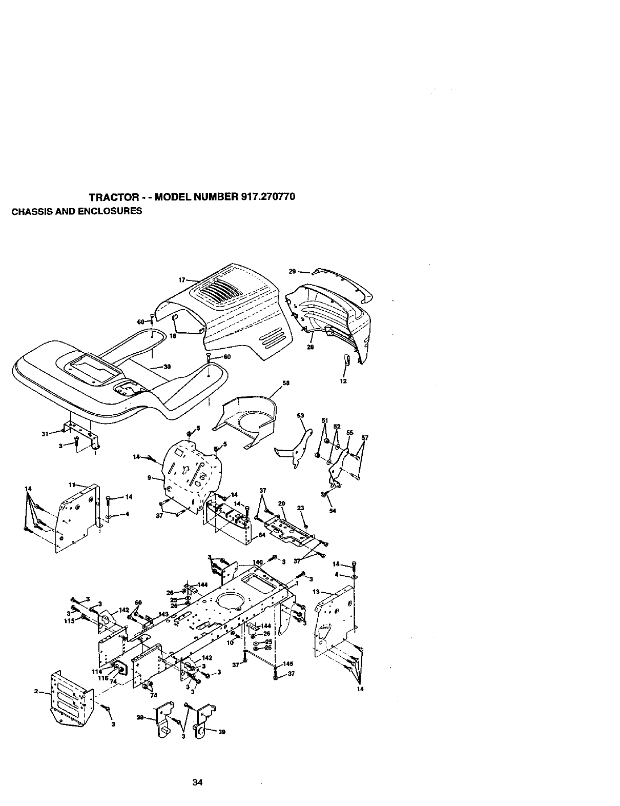
TRACTOR - - MODEL NUMBER 917.270770
CHASSIS AND ENCLOSURES
28 P
58 12
14 11
4
37
23 54
14
34
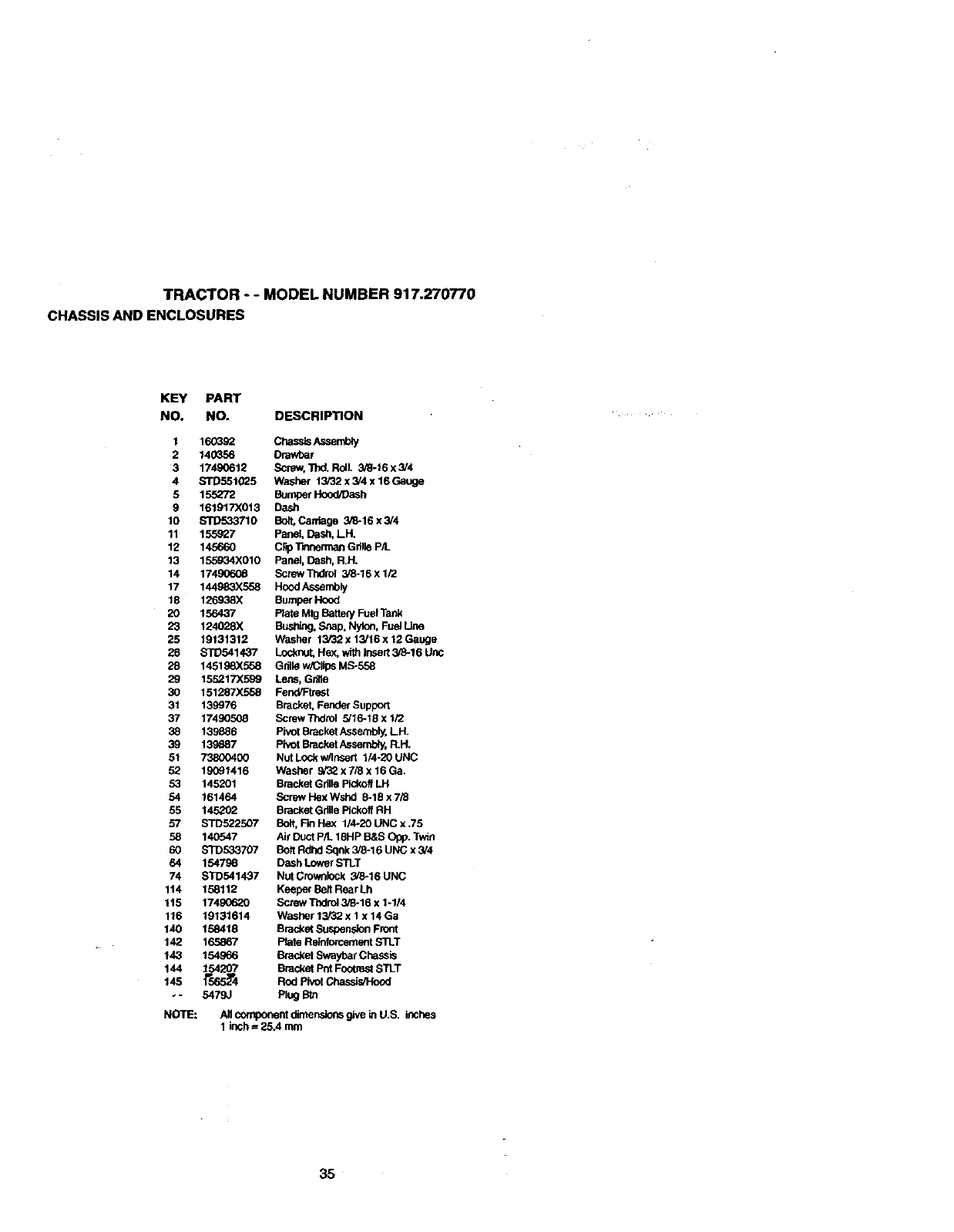
TRACTOR - -MODEL NUMBER 917.270770
CHASSIS AND ENCLOSURES
KEY PART
NO. NO. DESCRIPTION
1 160392 Chessis Assembly
2 140356 Drawbar
3 17490612 Screw, TI_ Rolt. 3/8-16 x 3/4
4 STD551025 Washer 13/32 x 3/4 x 16 Gauge
5 155272 Bomper Hood, Oash
9 161917X013 Dash
10 STD533710 Bolt, Carriage 3_-16 x 3/4
11 155927 Panel, Dash, LPL
12 145660 C,p T_nnerman Grille P/L
13 155934X010 Panel, Dash, R.H.
14 17490608 Screw "l]_lrol 3/6-16 x 1/2
17 144983X558 Hood Assernbly
18 126938X Bumper Hood
20 156437 Plate Mtg Batte_ Fuel Tank
23 124028X Busl_ng, S,"mp,Nylon, Fuel Une
25 19131312 Washer 13/32 x 13/16 x 12 Gauge
26 STD541437 Loc_ Hex, with insert 3/6-16 Uric
28 145198X558 Grille w/Clips MS-558
29 155217X599 Lens, Gdlle
30 151287X558 Fend/Ftrest
31 139976 Bracket, Fender Support
37 174_K)508 ScrewTndrol 5/16-18 x 1i2
38 139e86 P;vot Bracket Assembly, LH.
39 139687 Pivot Bracket Assembly, R.H.
51 73800400 Nut LOC_w/Insert 1/4-20 UNC
52 1_91416 Washer 9/32 x 7/8 x 16 Ga.
53 145201 Bracket Gdlle Pickoff LH
54 161464 Screw Hex Wshd 8-18 x 7/8
55 145202 Bracket Grille Pickoff RH
57 STD522507 Bolt, Fin Hex 1/4-20 UNC x .75
58 140547 Air Duct P/L 18HP B&S OR). Twin
60 STD533707 Bolt Rdhd Sqnk 3/8-16 UNC x 3/4
64 154798 Dash Lower STLT
74 STD541437 Nut Crownlock 3/8-16 UNC
114 158112 Keeper Belt Rear Lh
115 17490620 Screw "rhdrol3/8-16 x 1-1/4
116 19131614 Washer 13/32 x 1 x 14 Ga
140 158418 Bracket Suspension Front
142 165867 Plate Retnfomemeflt STLT
143 154966 Bracket Swaybar Chessle
144 _54565_4 Bracket Pnt Footrest STLT
145 Rod Pivot Cha_
o- 5479J Plug Bm
NOTE_ AI_componentdimensionsg_veinU.S. itches
Iinch = 25.4 mm
35
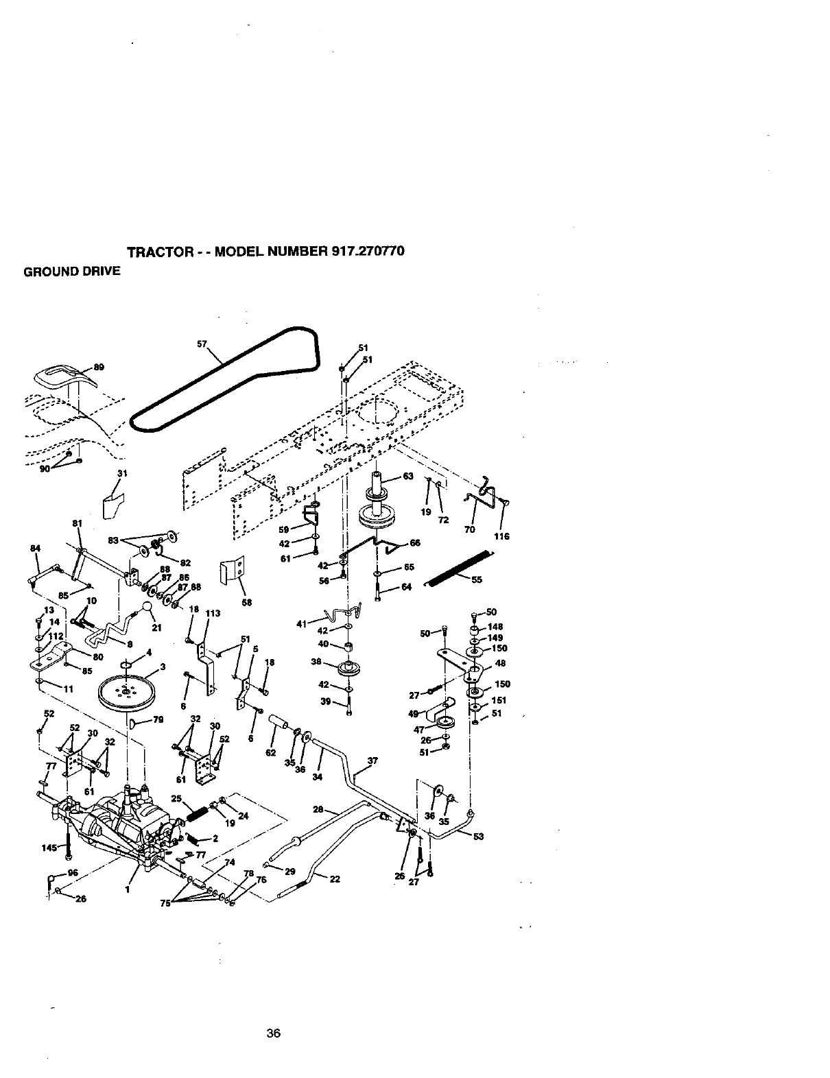
TRACTOR -- MODEL NUMBER 917.270770
GROUND DRIVE
57
84
!
58
113
51 5
18
116
50 -149
r,-150
p_48
_1 _ i _ 150
+. 151
•51
37
26 27
36
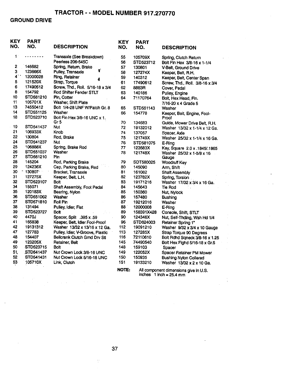
TRACTOR - - MODEL NUMBER 917.270770
GROUND DRIVE
KEY PART KEY PART
NO. NO. DESCRIPTION NO. NO. DESCRIPTION
1........
2146682
3 123666X
4" 12000028
5 121520X
6 17490512
8 154792
10 STD561210
11 105701X
13 74550412
14 BTD551125
18 STD523710
19 STD541437
21 106933X
22 130804
24 STD541237
25 106888X
26 STD551037
27 STD561210
28 145204
29 124236X
30 _ 130807'
31 127275X
32 STD523107
34 155071
35 120183}{
36 STD551062
37 STD571810
38 131494
39 STD523727
40 4470,.I
41 165838
42 19131312
47 127783
48 154407
49 123205X
50 STD523715
51, ,S]'D541437
52 STD541431
53 105710X
Transaxle (See Breakdown) 55 105709X
Peerless206-545C 56 STD523712
Spdng, Return,Brake 57 130801
Pulley,Trensaxle I' 58 127274X
Ring,Retainer _59 140312
Strap, Torque 81 17490612
Screw,Thd., Roll. 5/16-18 x 3/4 62 8883R
Rod ShiftarFender STLT 63 140186
Pin, Cotter 64 71170764
Washer, ShiftPlate
Bolt 1/4-28 UNF W/Patch Gr. 8 65 STD551143
Washer 66 154778
BoltFin Hex 3/8-16 UNC x 1.
Gr 5 70 134683
Nut 72 19132012
Knob 74 137057
Rod,Brake 75 121749X
Nut 76 STD581075
Spdng, Brake Rod 77 123583X
Washer 78 121748X
Pin
Rod,Parking Brake 79 SDT580025
Cap, Parking Brake, Red 80 145090
Bracket,Transaxle 81 161082
Keeper, Belt,L.H. 82 123782X
Bolt 83 19171216
Shaft Assembly,Foot Pedal 84 145643
Beadng, Nylon 85 150360
Washer 86 157480
RollPin 87 19212016
Pulley,Idler,Flat 88 12000008
Bolt 89 158391X428
Spacer,Split .395 x .59 90 124346X
Keeper, Belt,IdlerFool-Proof 96 STD624003
Washer 13/32 x 13/16 x 12 Ga. 112 19091210
Pulley,Idler,V-Groove, Plastic 113 127285X
BeUcrankClutch Grad Dr,/Stl 116 72110610
Retainer,Belt 145 74490540
Bolt 148 159103
NutCrown Lock 3/8-16 UNC 149 122052X
NutCrown Lock 5/16-18 UNC 150 150935
Link,Clutch 151 19133210
NOTE:
Spring, ClutchReturn
Bolt Fin Hex 3/6-16 x 1-1/4
V-Belt, Ground Ddve
Keeper, Belt,R.H.
Keeper, Belt,Center Span
Screw,Thd., Roll. 3/8-16 x 3/4
Cover, Pedal
Pulley,Engine
Bolt,Hex Head, Fin.
7/16-20 x 4 Grade 5
Washer
Keeper, Belt, Engine,Fool-
Proof
Guide,Mower Drive Belt,R.H.
Washer 13/32 x 1-1/4 x 12 Ga.
Spacer, Axle
Washer 25/32 x 1-1/4 x 16 Ga.
E-Ring
Key, Square 2.0 x .1845/.1865
Washer 25/32 x 1-5/8 x 16
Gauge
Woodruff Key
Arm, Shift
Shaft Assembly
Spdng, Torsion
Washer 17/32 x 3/4 x 16 Ga.
"ReROd
Nut, Nylook
Bushing
Washer
E-Ring
Console, Shift,STLT
Nut, Self-Thding,Wsh Hd 1/4
RetainerSpdng 1"
Washer 9/32 x 3/4 x 10 Gauge
Strap Torque90 Degrees
Bolt Rdhd Sqneck 3/6-16 x 1.25
Bolt Hex Flghd5/16-15 x Gr.5
Spacer
Spacer Retainer PM Mower
BushingNylonCollerad
Washer 13/32 x 2 x 10 Ga,
All componentdimensionsgivein U.S.
inches 1 ir_h = 25.4 mm
37
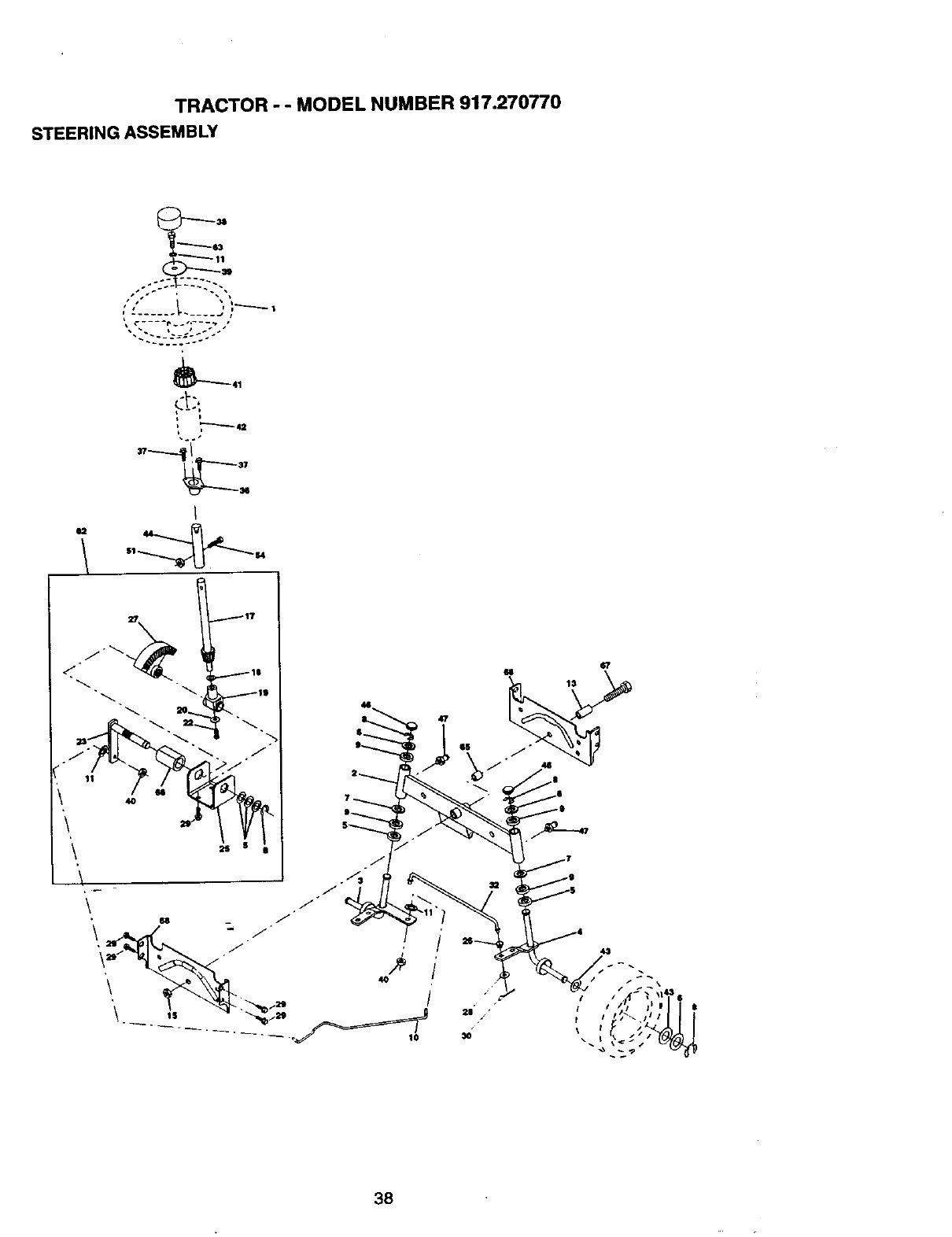
TRACTOR - - MODEL NUMBER 917.270770
STEERING ASSEMBLY
t t i_1
-- .... .o-
p'---_s;
O2 44
47
IS
38
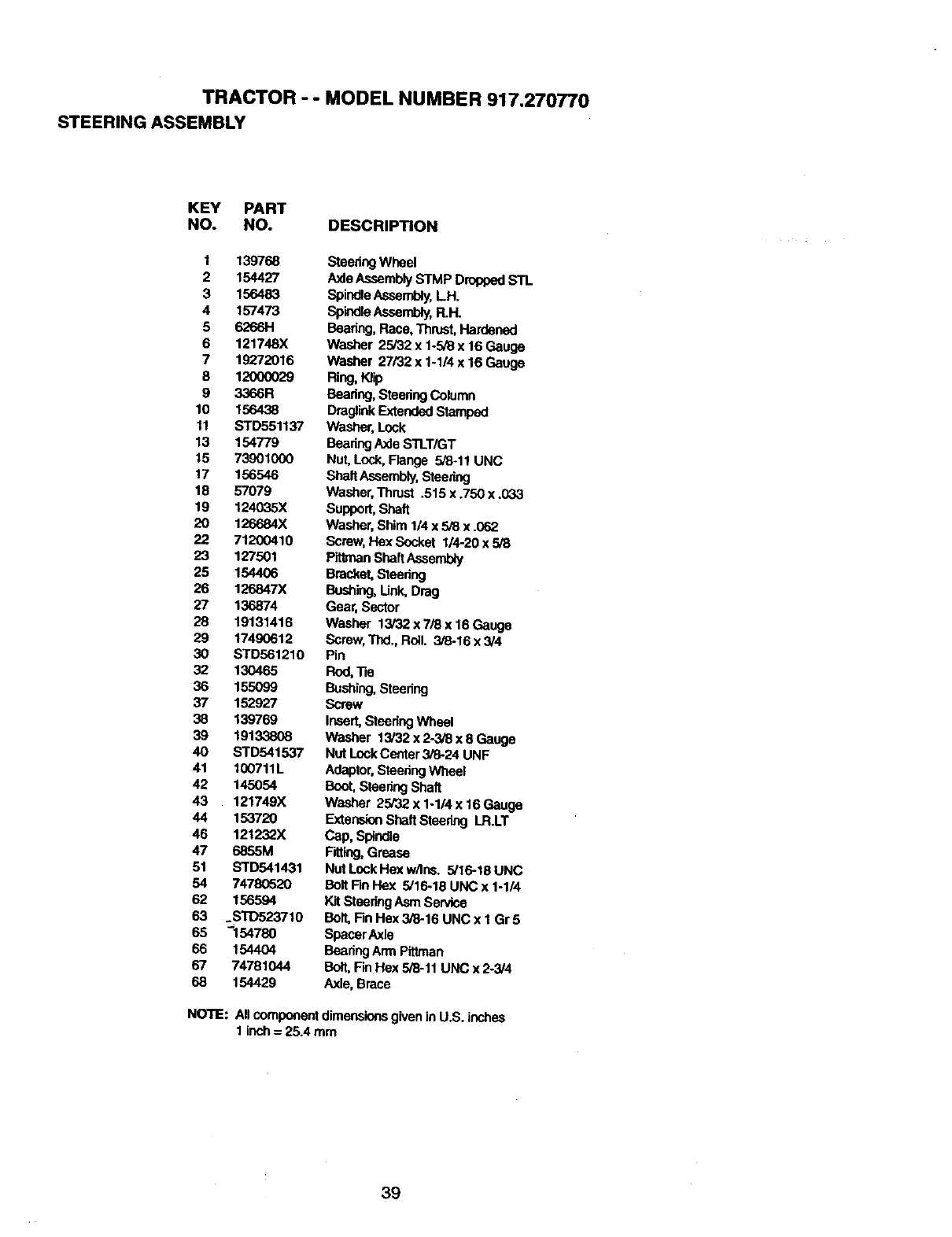
TRACTOR - - MODEL NUMBER 917,270770
STEERING ASSEMBLY
KEY PART
NO. NO. DESCRIPTION
1 139768
2 154427
3 156483
4157473
562S6H
6 121748X
7 19272016
8 12000029
9 3366R
10 156438
11 STD551137
13 154779
t5 73901000
17 156546
18 57079
19 124035X
2O 126684X
22 71200410
23 127501
25 154406
26 126847X
27 136874
28 19131416
29 17490612
30 STD561210
32 130465
36 155099
37 152927
38 139769
39 19133808
40 STD541537
41 100711L
42 145054
43 121749X
44 153720
46 121232X
47 6855M
51 STD541431
54 74780520
62 156594
63 _STD523710
65 "'154780
66 1544O4
67 74781044
68 154429
SteeringWheel
AxleAssemblySTMP DroppedSTL
Spi_le kssembly, LH.
Sp'mdleAssembly,R.H.
Beating, Race, Thn,tst,Hardened
Washer 25/32 x 1-5/8 x 16 Gauge
Washer 27/32 x 1-114x 16 Gauge
Ring,Klip
Bearing,SteeringColumn
DraglinkExtendedStamped
Washer, Lock
BearingAxle STLT/GT
Nut, Lock,Range 518-11UNC
ShaftAssembly,Steering
Washer,Thrust .515 x .750 x .033
Support, Shaft
Washer, Shim 1/4 x 5/8 x.062
Screw,Hex Socket 1/4-20 x 5/8
PitlmanShaftAssernd_
Bracket Steedng
Bushing,Link, Drag
Gear, Sector
Washer 13/32 x 7/8 x 16 Gauge
Screw,Thd., Roll. 3/6-16 x 3/4
Pin
Rod, Tie
Bushing,Steedng
Screw
Insert,Steedng Wheel
Washer 13/32 x 2-3/8 x 8 Gauge
Nut LockCenter 3/8-24 UNF
Adaptor,SteedngWheel
Boot, SteeringShaft
Washer 25/32 x 1-1/4 x 16 Gauge
ExtensionShaftSteering LR.LT
Cap, Spindle
F_ing, Grease
Nut LockHex w/Ins. 5/16-18 UNC
Bolt FinHex 5/16-18 UNC x 1-1/4
Kit Steedng Asm Service
Bolt,Rn Hex 3/8-16 UNC x 1 Gr5
Spacer Axle
BearingArm Plttman
Bolt,FinHex 5/8-11 UNC x 2-3/4
Axle, Brace
NOTE: All componentdimensionsgivenin U.S. inches
1 inch = 25.4 mm
39
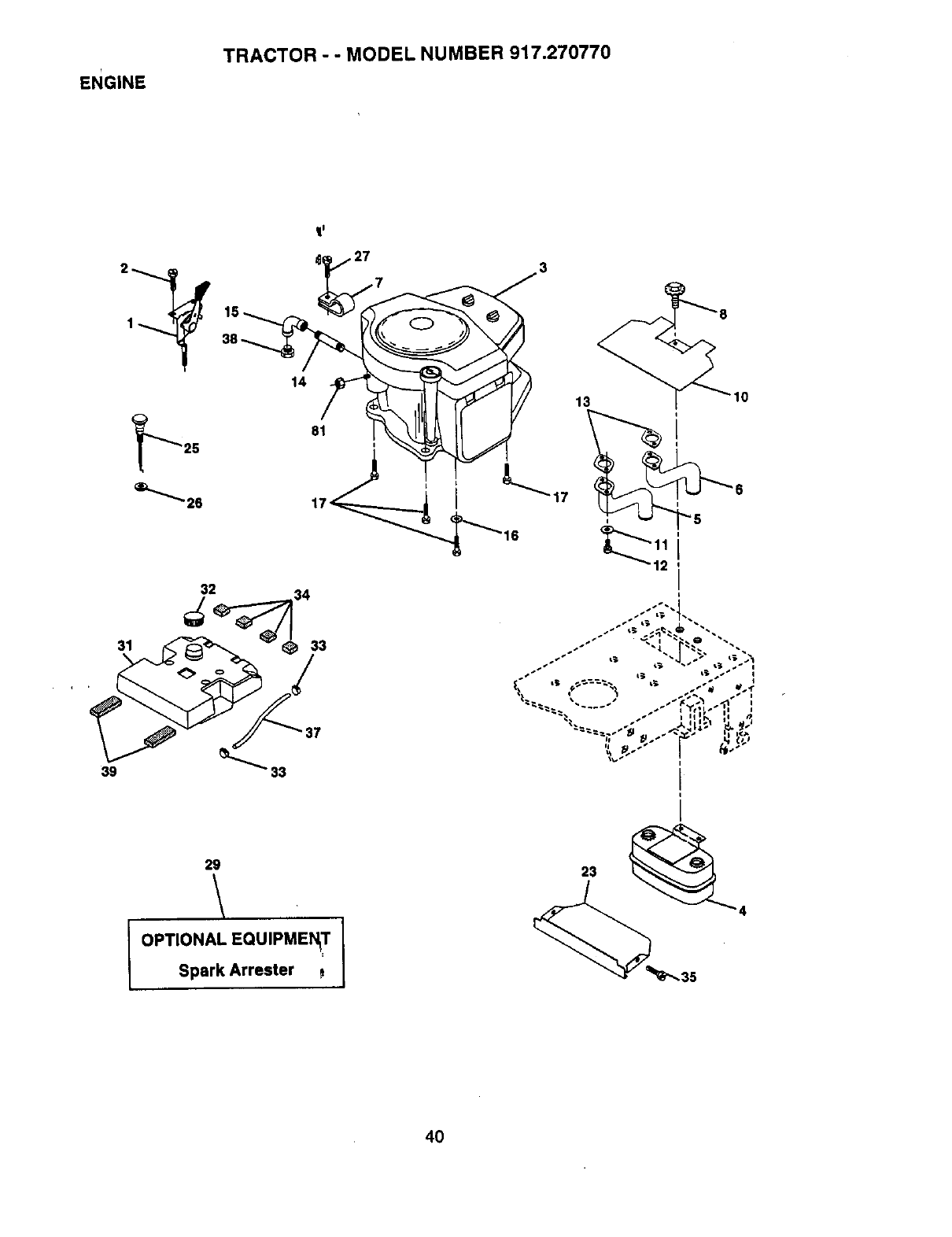
ENGINE
TRACTOR - -MODEL NUMBER 917.270770
11
39
31
32 34
29
\
OPTIONAL EQUIPMENqT
Spark Arrester
4O
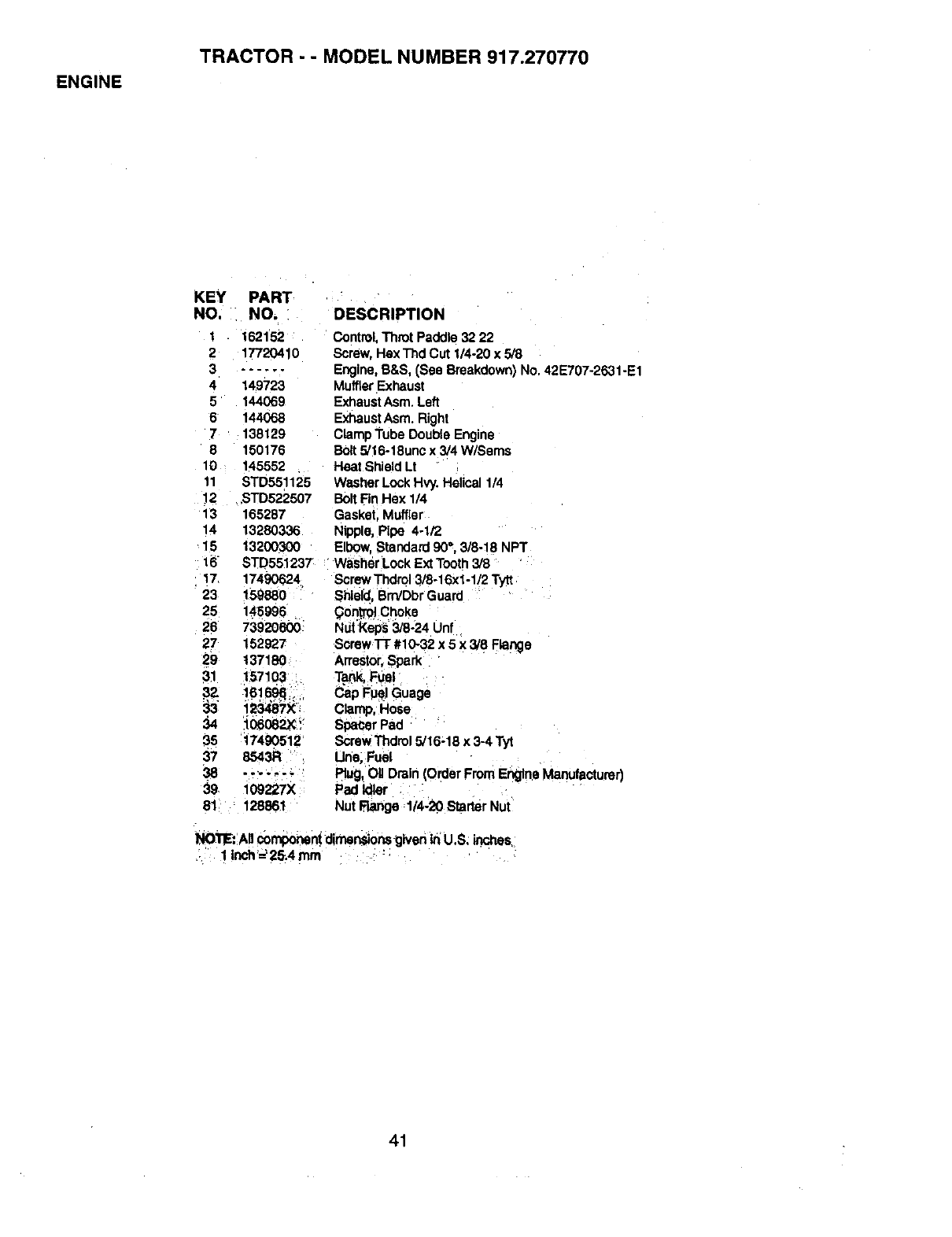
ENGINE
TRACTOR - - MODEL NUMBER 917.270770
KEY PART
NO. NO. DESCRIPTION
1
2
3
4
5
6
7
8
10
11
12
13
14
15
16
17
23
25
26
27
29
31
38
37
39
162152
17720410
149723
144069
144068
138129
150176
145552
STD551125
STD522507
165287
13280336
13200300
Control,Throt Paddle 32 22
Screw, Hex'_d Cut 1/4-20 x 5/8
Engine,B&S, (See Breakdown) No. 42E707-2631-E1
MufflerExhaust
ExhaustAsm. Left
ExhaustAsm. Right
ClampTube Double Engine
Bolt5/16-18unc x 3/4 W/Sems
Heat Shield Lt
Washer Lock Hvy. Helical 114
BoltRr_Hex 1/4
Gasket, Muffler
Nipple, Pipe 4-1/2
Elbow, Standard 90°, 3/8-18 NPT
STD551237 "WasherLock ExtTooth3/8
17490624
159880
145996
73920600
152927
137180
157103
16_ _,r
123487X;
:io oe2x
17490512
8543R
109227X
128861
Screw Thdrol3/8-16xl -1/2 Tytt
Shield, Bm/Dbr Guard
gon_:r_ Cr_oke
NtJt:Keps3/8-24 Unf
Screw Tr #10-32 x 5 x 3/8 Flange
Arrestor.Spark
Tap.k,Fuel
Cap Fuel Guage
Clamp, Hose
Spacer Pad
Screw Thdrol5/16-18 x 3-4 Tyt
Line, Fuel
Rug, Og Drain (Order From EngineManufacturer)
Pad Idler
Nut Range 1/4-20 Starter Nut
NOTE:All componentdimensionsgiveninU.S; inches
11nch'_25.4nlrn
41
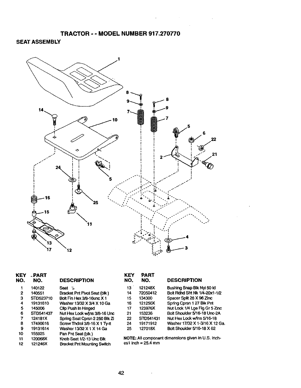
TRACTOR - - MODEL NUMBER 917.270770
SEAT ASSEMBLY
21
KEY -PART
NO. NO. DESCRIPTION
1 140122
2 140551
3 STD523710
4 19131610
5 145006
6 STD541437
7 124181X
8 17490616
9 19131614
10 155925
11 120068X
12 121246X
KEY PART
NO. NO.
Seat _, 13" 121248X
BracketPntPivotSeat (blk) 14 72050412
BoltFinHex 3/8-16uncX 1 15 134300
Washer13/32 X 3/4 X 10 Ga 16 121250X
C!ipPush In Hinged 17 123976X
Nut Hex Lockw/ins 3/8-16 Unc 21 153236
SpringSeat Cprsn2 250 BIkZi 22 STD541431
ScrewThdrol3/8-16 X 1Ty4t 24 19171912
Washer 13/32X 1 X 14 Ga 25 127018X
Pan Pnt Seat (blk)
Knob Seat lf2-13 Unc BIk
BracketPet MountingSwitch
DESCRIPTION
BushingSnap BIk Ny150 Id
BoltRdhd Sht Nk 1/4-20x1-1/2
Spacer Split28 X 96 Zinc
SpdngCprsn 127 BIk Pnt
NutLock 1/4Lge Fig Gr 5 Zinc
BoltShoulder5/16-18 Unc-2A
NutHex Lock w/lns5/16-18
Washer 17/32 X 1-3/16 X 12Ga,
BoltShoulder 5/16-18 X 62
NOTE: AIrcomponentdimensions given in U.S. inch-
esl inch=25.4 mm
42
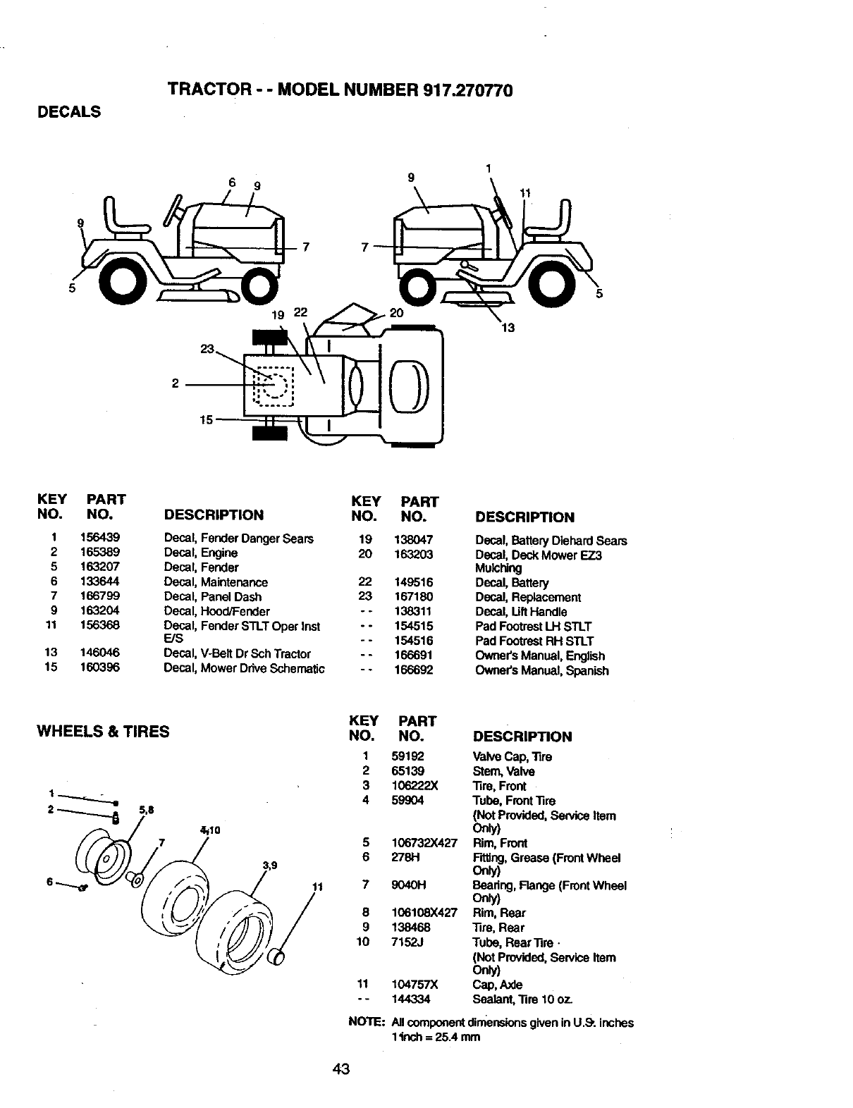
DECALS
TRACTOR - - MODEL NUMBER 917.270770
6 9
19 22
2
13
11
5
KEY
NO.
1
2
5
6
7
9
11
13
15
PART KEY PART
NO. DESCRIPTION NO. NO.
156439 Decal, Fender Danger Sears 19 138047
165389 Decal, Engine 20 163203
163207 Decal, Fender
133644 Decal, Maintenance 22 149516
166799 Decal, Panel Dash 23 167180
163204 Decal, Hood/Fender - - 138311
156368 Decal, Fender STLTOper Inst -- 154515
E/S - - 154516
146046 Decal, V-Belt Dr Sch Tractor - - 166691
160396 Decal, Mower DriveSchematic - -166692
DESCRIPTION
Decal, Battery Diehard Seam
Decal, Deck Mower EZ3
Mulching
Decal, Battery
Decal, Replacement
Decal, Uft Handle
Pad FootrestLH STLT
Pad FootrestRH STLT
OwneCsManual, English
OwneCsManual, Spanish
WHEELS & TIRES
11
KEY
NO,
1
2
3
4
8
9
10
11
°.
NOTE:
PART
NO. DESCRIP11ON
59192 ValveCap, "nre
65139 Stern,Valve
106222X "13m,Front
59904 Tube, Front"nre
(Not Provided,Service Item
One,)
106732X427 Rim, Front
2781-1 Fitting,Grease (FrontWheel
one)
9040H Beadng, Flange (FrontWheel
one/)
106108X427 Rim, Rear
138468 "nre,Rear
7152J Tube, Rear "nm -
(Not Provided.Service Item
Only)
104757X Cap, Axle
144334 Sealant, "lira 10oz.
Allcomponentdimensionsgivenin U._ inches
l_'_ch : 25.4 mm
43
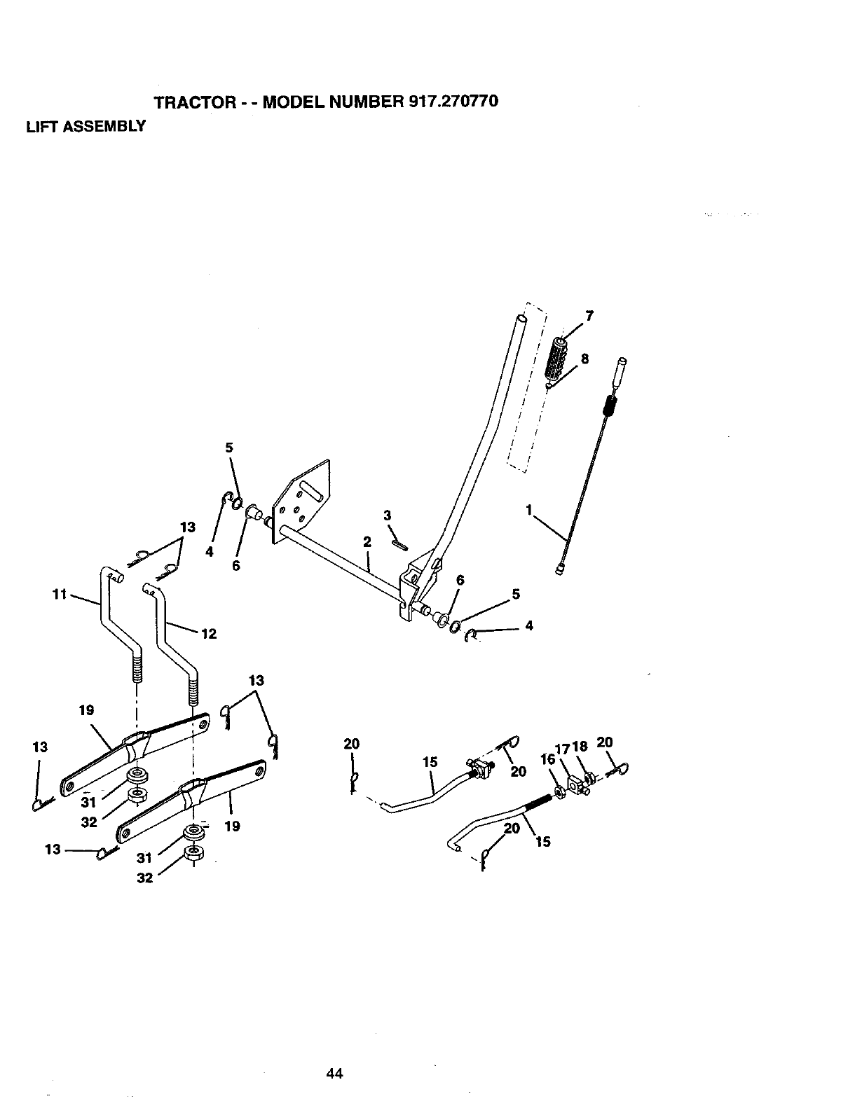
TRACTOR --MODEL NUMBER 917.270770
LIFT ASSEMBLY
7
13
5
46
19
13
31
32
13
19
2O
15
44
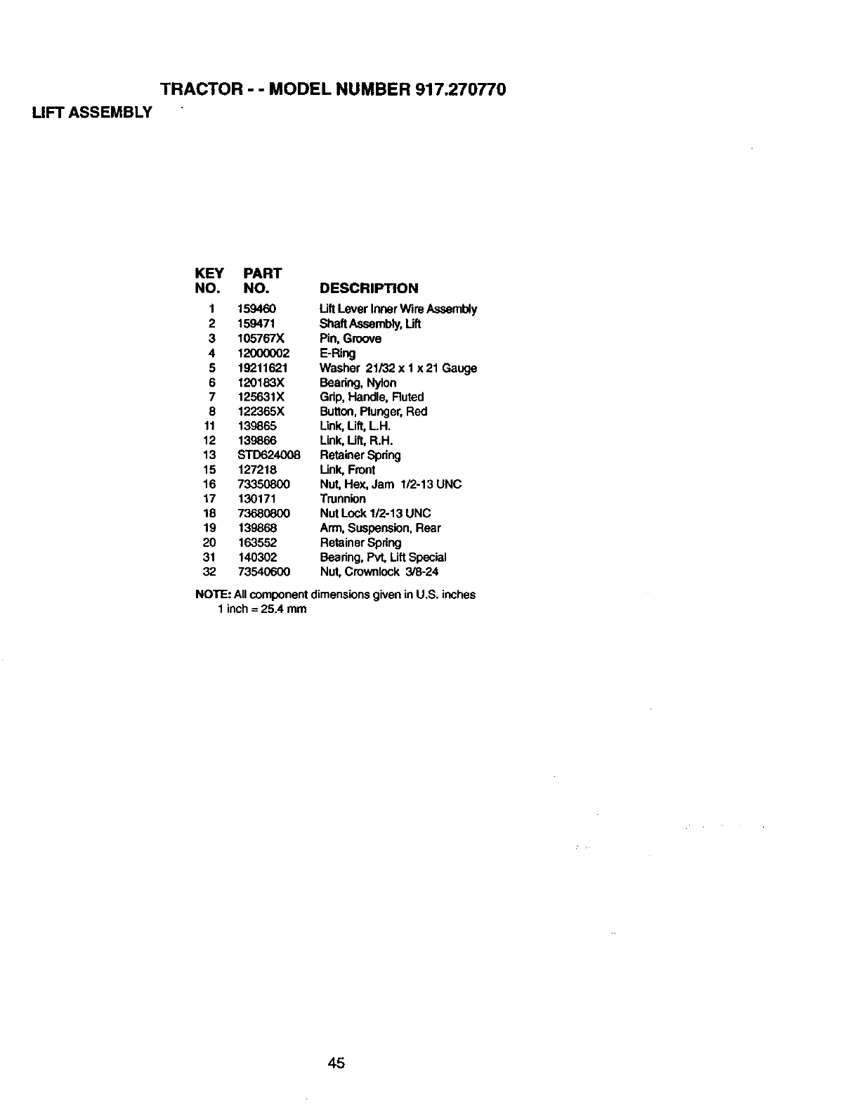
TRACTOR - - MODEL NUMBER 917.270770
LIFT ASSEMBLY
KEY PART
NO. NO. DESCRIPTION
1 159460 LiftLever Inner Wire Assembly
2 159471 ShaftAssembly,Lift
3 105767X Pin, Groove
4 12000002 E-Ring
5 19211621 Washer 21/32 x I x 21 Gauge
6 120183X Bearing, Nylon
7 125631X Grip, Handle, Ruted
8 122365X Button,Plunger,Red
11 139865 Link, Uft, LH,
12 139866 Link, Oft, R.H.
13 STD624008 Retainer Spdng
15 127218 Link, Front
16 73350800 Nut, Hex, Jam 1/2-13 UNC
17 130171 Trunnion
18 73680800 Nut Lock 1/2-13 UNC
19 139868 Arm, Suspension,Rear
20 163552 Retainer Spring
31 140302 Bearing, Pvt, LiftSpecial
32 73540600 Nut, Crownlock 3/8-24
NOTE: Allcomponentdimensionsgivenin U.S. inches
1 inch= 25.4 mm
45
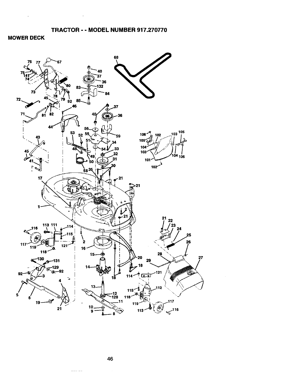
TRACTOR - - MODEL NUMBER 917.270770
MOWER DECK
_132
17 !_ 21
>21
5
4
6
21
27
46
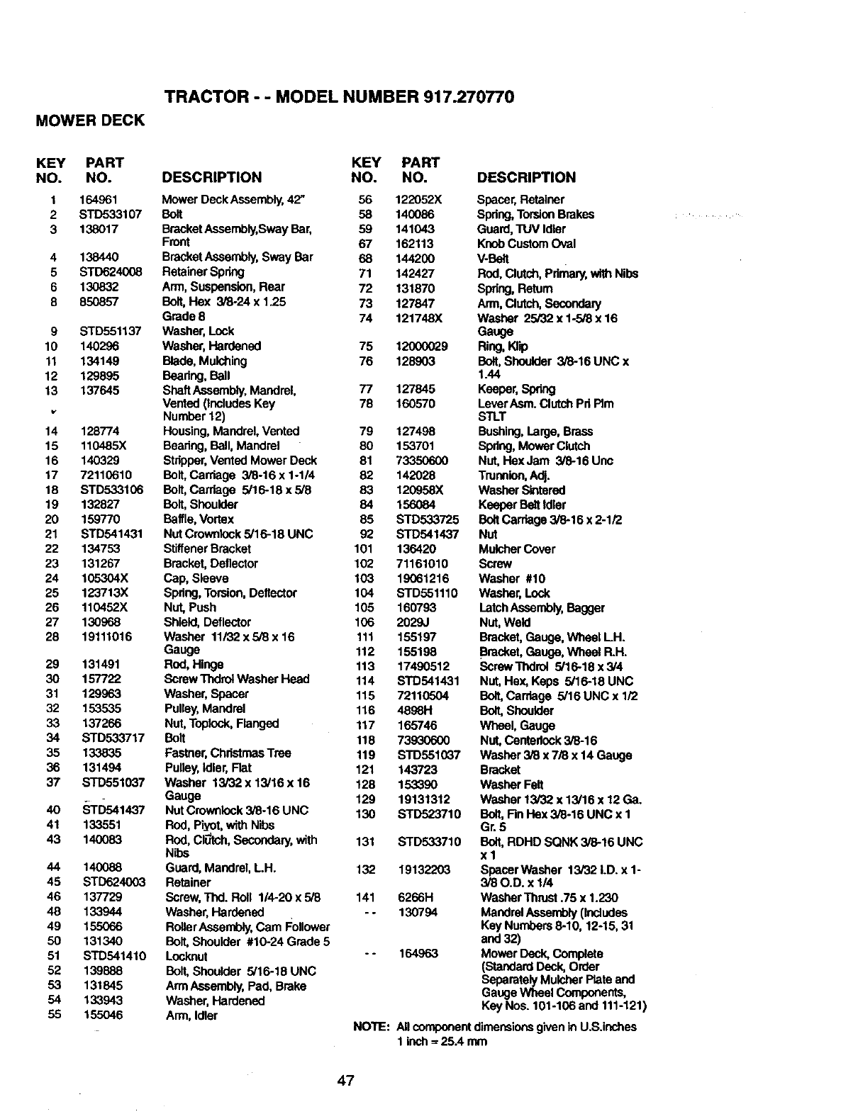
TRACTOR - -MODEL NUMBER 917.270770
MOWER DECK
KEY PART KEY PART
NO. NO. DESCRIPTION NO. NO.
1
2
3
4
5
6
8
9
10
11
12
13
14
15
16
17
18
19
20
21
22
23
24
25
26
27
28
29
3O
31
32
33
34
35
36
37
4O
41
43
44
45
46
48
49
50
51
52
53
54
55
164961 Mower Deck Assembly,42" 56 122052X
STD533107 Bolt 58 140086
138017 BracketAssembly,Sway Bar, 59 141043
Front 67 162113
138440 BracketAssembly,Sway Bar 68 144200
STD624008 RetainerSpring 71 142427
130832 Arm, Suspension,Rear 72 131870
850857 Bolt, Hex 3/8-24 x 1.25 73 127847
Grade 8 74 121748X
STD551137 Washer, Lock
140296 Washer, Hardened 75 12000029
134149 Blade, Mulching 76 128903
129895 Beadng, Ball
137645 ShaftAasernbly,Mandrel, 77 127845
Vented (includesKey 78 160570
Number 12)
128774 Housing,Mandrel,Vented 79 127498
110485X Beedng, Ball,Mandrel 80 153701
140329 Stripper,Vented Mower Deck 81 73350600
72110610 Bolt, Carriage 3/8-16 x 1-1/4 82 142028
STD533106 Bolt, Cardage 5/16-18 x 5/8 83 120958X
132827 Bolt,Shoulder 84 156084
159770 Baffle, Vortex 85 STD533725
STD541431 Nut Crowaiock5/16-18 UNC 92 STD541437
134753 StiffenerBracket 101 136420
131267 Bracket, Deflector 102 71161010
105304X Cap, Sleeve 103 19061216
123713X Spring,Torsion,Deflector 104 STD551110
110452X Nut, Push 105 160793
130968 Shield, Deflector 106 2029J
19111016 Washer 11/32 x 5/8 x 16 111 155197
Gauge 112 155198
131491 Rod, Hinge 113 17490512
157722 Screw Thdro_Washer Head 114 STD541431
129963 Washer, Spacer 115 72110504
153535 Pulley,Mandrel 116 4898H
137266 Nut, Topiock,Flanged 117 165746
STD533717 Bolt 118 73930600
133835 Fastner,ChristmasTrae 119 STD551037
131494 Pulley,Idler, Flat 121 143723
STD551037 Washer 13/32 x 13/16 x 16 128 153390
Gauge 129 19131312
_rD541437 Nut Crowaiock 3/8-16 UNC 130 STD523710
133551 Rod, Piyot, with Nibs
140083 Rod, ClUtch,Secondary,with 131 STD533710
Nibs
140088 Guard, Mandrel, LH. 132 19132203
STD624003 Retainer
137729 Screw,Thd. Roll 114-20x 5/8 141 6266H
133944 Washer, Hardened - - 130794
155066 RoUerAssembly,Cam Follower
131340 Bolt,Shoulder #10-24 Grade 5
STD541410 Locknut -- 164963
139888 Bolt,Shoulder 5/16-18 UNC
131845 ArmAssembly,Pad, Brake
133943 Washer,Hardened
155046 Arm, Idler
DESCRIPTION
Spacer,Retainer
Spdng,TorsionBrakes
Guard,"I_V Idler
KnobCustom Oval
V-Bait
Rod, Clutch,Pdmary,withNibs
Spring, Return
Arm, Clutch,Secondary
Washer 25732x 1-5/8 x 16
Gauge
Ring, Klip
Bolt,Shoulder 3/8-16 UNC x
1.44
Keeper, Spring
Lever Asm. Clutch Pd Rm
STLT
Bushing,Large, Brass
Spdng, Mower Clutch
Nut, HoX Jam 3/8-16 Unc
Trunnion,Adj.
Washer Sintared
Keeper BeltIdler
BoltCarriage 3/6-16 x 2-1/2
Nut
Mulcher Cover
Screw
Washer #10
Washer, Lock
Latch Assembly,Bagger
Nut,Weld
Bracket,Gauge, Wheel LH.
Bracket,Gauge, Wheel R.H.
ScrawThdrol 5/16-18 x 3/4
Nut, Hey.,Keps 5/16-18 UNC
Bolt,Carriage 5/16 UNC x 1/2
Bolt,Shoulder
Wheel, Gauge
Nut, Centedock3/8-16
Washer 3/8 x 7ABx 14 Gauge
Bracket
Washer Felt
Washer 13/32 x 13/16 x 12Ga.
Bolt, Rn Hex 3/6-16 UNC x 1
Gr. 5
Bolt,RDHD SQNK 3/8-16 UNC
xl
Spacer Washer 13/32 I.D. x 1-
3/80.D. x 1/4
Washer Thrust.75 x 1.230
Mandrel Assembly(Includes
Key Numbers 8-10, 12-15, 31
and32)
Mower Deck, Complete
(Standard Deck, Order
SeparatelyMulcher Plate and
Gauge Wheel Components,
Key Nos. 101-106 and 111-121)
NOTE: Allcemponent dimensionsgivenin U.S.inches
1 inch= 25.4 rnnl
47
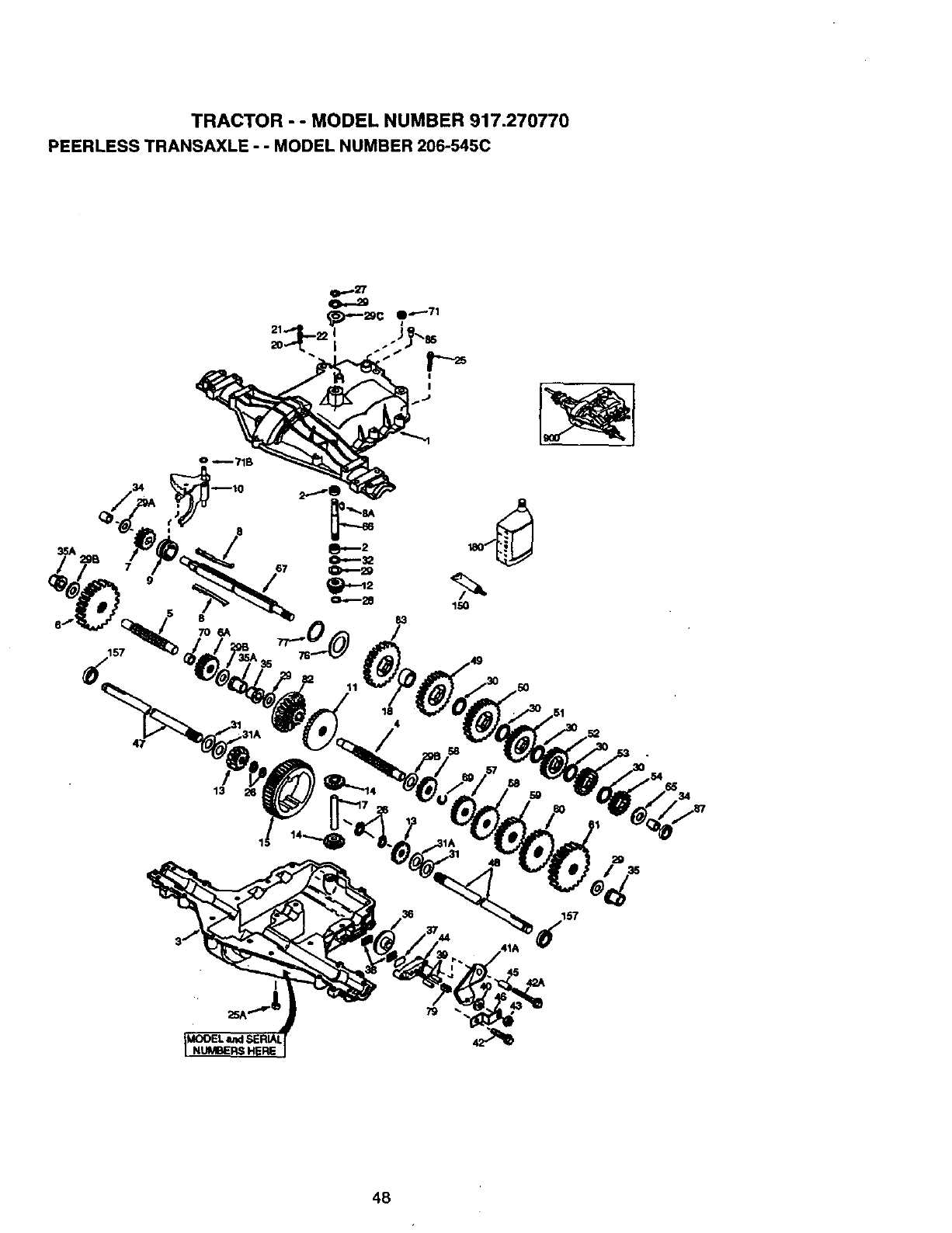
TRACTOR - - MODEL NUMBER 917.270770
PEERLESS TRANSAXLE - - MODEL NUMBER 206-545C
157
o -- 71B
11
150
13
48
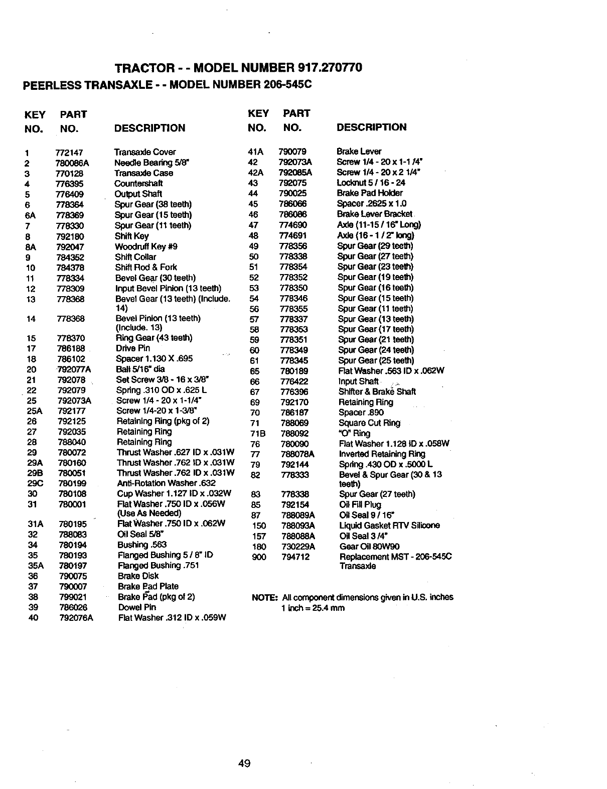
TRACTOR - - MODEL NUMBER 917.270770
PEERLESS TRANSAXLE - - MODEL NUMBER 206-545C
KEY PART KEY PART
NO. NO. DESCRIPTION NO. NO.
1772147 Transaxla Cover 41A 790079
2 780086A Needle Beadng _42 792073A
3 770128 Transaxle Case 42A 792065A
4 776395 Countershaft 43 792075
5 776409 OutputShaft 44 790025
6 778364 Spur Gear (38 teeth) 45 78606o6
6A 778369 Spur Gear (15 teeth) 46 786086
7 778330 Spur Gear (11 teeth) 47 774690
8 792180 ShiftKey 48 774691
8A 792047 WoodruffKey #9 49 778356
9 784352 ShiftCollar 50 778338
10 784378 Sh_ Rod & Fork 51 778354
11 778334 Bevel Gear (30 teeth) 52 778352
12 778309 Input Bevel Pinion (13 teeth) 53 778350
13 778368 Bevel Gear (13 teeth) (Include. 54 778346
14) 56 778355
14 778368 Bevel Pinion (13 teeth) 57 778337
(Include. 13) 58 778353
15 778370 Ring Gear (43 teeth) 59 778351
17 786188 Drive Pin 60 778.349
18 786102 Spacer 1.130 X .695 61 778345
20 ,792077A Ball 5/16" dia 65 780189
21 792078 Bet Screw 3/8 -16 x 3/8" 66 776422
22 792079 Spring .310 OD x .625 L 67 776396
25 792073A Screw 1/4 -20 x 1-1/4" 69 792170
25A 792177 Screw 1/4o20x 1-3/8_70 786187
26 792125 Retaining Ring (pkgof 2) 71 788069
27 792035 Retaining Ring 71B 788092
28 788040 Retaining Ring 76 780090
29 780072 ThrustWasher .627 ID x .031W 77 788078A
29A 780160 Thrust Washer .762 ID x .031W 79 792144
29B 780051 Thrust Washer .762 ID x .031W 82 778333
29C 780199 Anti-RotationWasher .632
30 780108 Cup Washer 1.127 ID x .032W 83 778338
31 780001 FlatWasher .750 ID x .056W 85 792154
(Use As Needed) 67 788089A
31A 780195 FlatWasher .750 ID x .062W 150 788093A
32 788083 Oil Seal 5/6, 157 788088A
34 780194 Bushing.563 180 730229A
35 780193 Flanged Bushing 5 /8"ID 900 794712
35A 780197 Ranged Bushing.751
36 790075 Brake Disk
37 790007 Brake Bad Plate
38 799021 Brake I_ad(pkgof 2) NOTE."
39 786026 Dowel Pin
40 792076A FlatWasher .312 ID x .059W
DESCRIPTION
Brake Lever
Screw 1/4 -20 x 1-114"
Screw114 - 20 x2114"
Loc_ut 5 /16- 24
Brake Pad Holder
Spacer .2625 x 1.0
Brake Levar Bracket
Axla (11-15 /16, Long)
Axla (16-1/2" long)
Spur Gear (29 teeth)
Spur Gear (27 teeth)
Spur Gear (23 teeth)
Spur Gear (19 teeth)
Spur Gear (16 teeth)
Spur Gear (15 teeth)
Spur Gear (11 teeth)
Spur Gear (13 teeth)
Spur Gear (17 teeth)
Spur Gear (21 teeth)
Spur Gear (24 teath)
Spur Gear (25 teeth)
Rat washer .563 ID x .062W
InputShaft ,
Shifter& Brake Shaft
RetainingRing
Spacer .890
Square Cut Ring
"O" Ring
Rat Washer 1.128 |D x .058W
InvertedRetainingRing
Spdng A30 OD x .5000 L
Bevel& Spur Gear (30 & 13
teeth)
Spur Gear (27 teeth)
Oil Fill Plug
OilSeal 9 /16,
LiquidGasket RTV Silk;one
Oil Seal 3/4"
Gear Oil 80W90
ReplacementMST -206-545(3
Transaxla
AllcomponentdimensionsgiveninU.S. inches
1 i_h = 25.4 mm
49
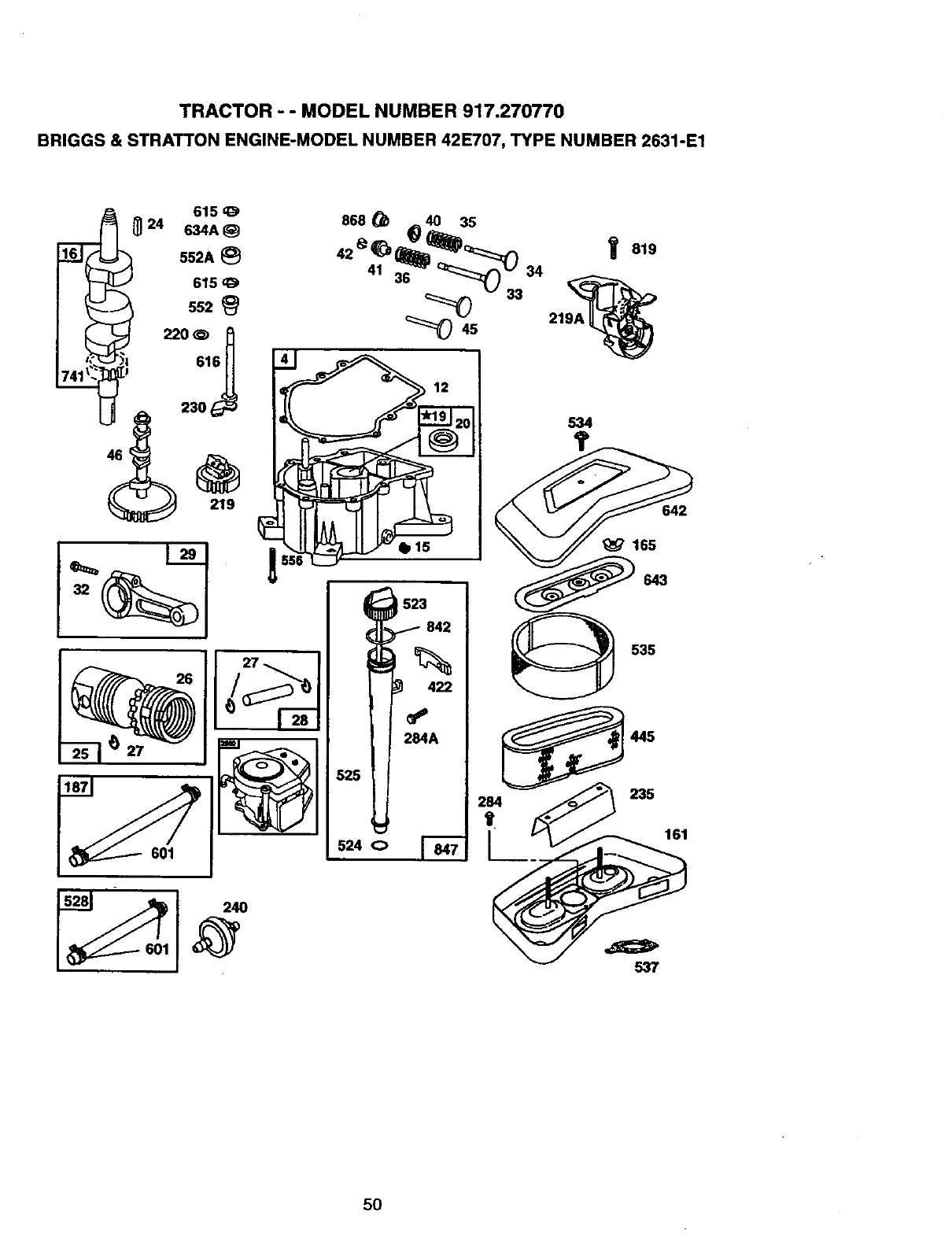
TRACTOR -- MODEL NUMBER 917.270770
BRIGGS & STRATTON ENGINE-MODEL NUMBER 42E707, TYPE NUMBER 2631-E1
601
523
842
422
2_A
528
524 0
535
445
537
5O
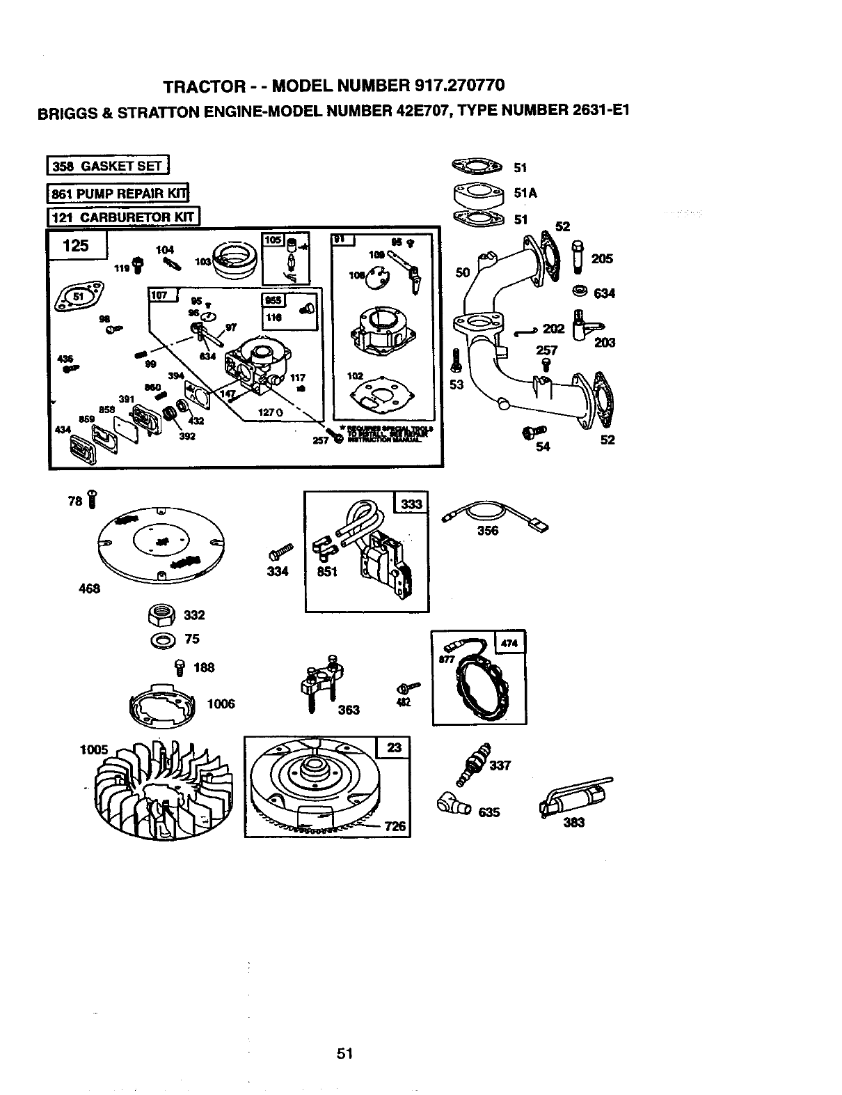
TRACTOR - - MODEL NUMBER 917.270770
BRIGGS & STRATTON ENGINE-MODEL NUMBER 42E707, TYPE NUMBER 2631-E1
1358 GASKET SET J 51
61
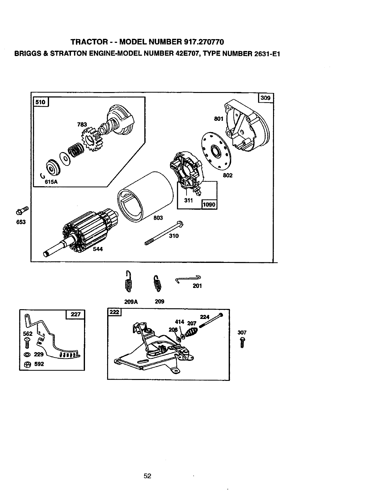
TRACTOR - o MODEL NUMBER 917.270770
BRIGGS & STRATTON ENGINE-MODEL NUMBER 42E707, TYPE NUMBER 2631-E1
653
615A
783 801
802
803
544
S92
52
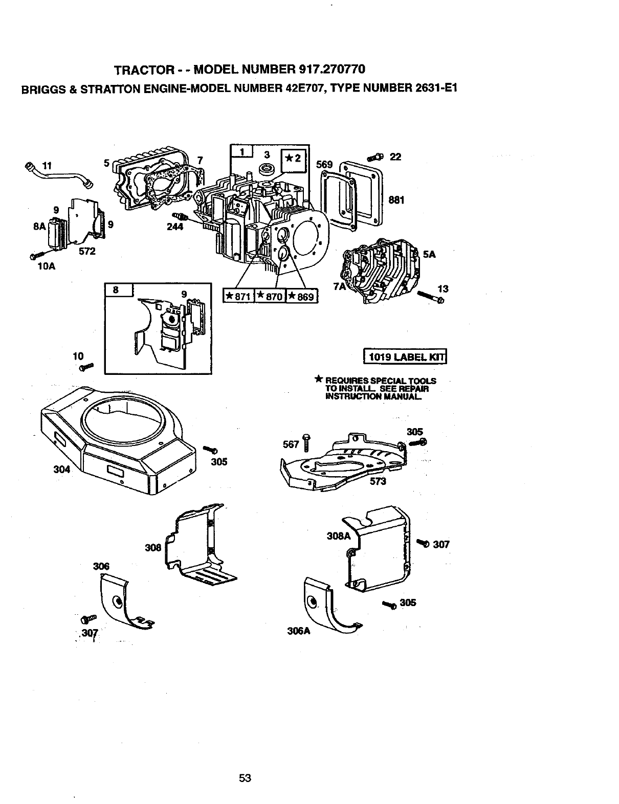
TRACTOR --MODEL NUMBER 917.270770
BRIGGS & STRA'rTON ENGINE-MODEL NUMBER 42E707, TYPE NUMBER 2631-E1
5
8A__2 9
10A
244
3
881
5A
IO
913
I1019 LABEL KITI
306A
53
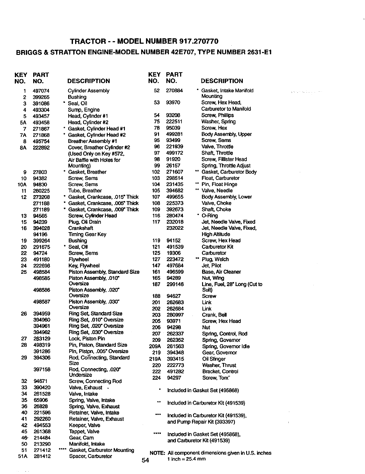
TRACTOR --MODEL NUMBER 917.270770
BRIGGS & STRATTON ENGINE-MODEL NUMBER 42E707, TYPE NUMBER 2631-E1
KEY PART KEY PART
NO. NO. DESCRIPTION NO, NO. DESCRIPTION
1 497074 CylinderAssembly 52 270884 "Gasket, IntakeManifold
2 399265 Bushing MounUng
3 391086 * Seal, Oil 53 93970 Screw, Hex Head.
4 493304 Sump, Engine Carburetorto Manifold
5 493457 Head, Cylinder#1 54 93208 Screw, Phillips
5A 493458 Head, Cylinder#2 75 222511 Washer, Spdng
7 271867 * Gasket, CylinderHead #1 78 95039 Screw,Hex
7A 271868 * Gasket, CylinderHead #2 91 499281 BodyAssembly,Upper
8 495754 BreatherAssembly #1 95 93499 Screw,Sen_
8A 222892 Cover, BreatherCylinder#2 96 221939 Valve, Throttle
(Used Onlyon Key #572, 97 499172 Shaft,Throttle
Air BafflewithHoles for 98 91920 Screw,FillisterHead
Mounting) 99 26157 Spdng, Throttle Adjust
9 27803 * Gasket, Breather 102 271607 "* Gasket, Carburetor Body
10 94382 Screw, Serns 103 298514 Float, Carburetor
10A 94830 Screw, Seres 104 231435 "* Pin, Float Hinge
11 280225 Tube, Breather 105 394682 ** Valve, Needle
12 273208 "GaskeLCrankcaea,.O15"Thick 107 499655 BodyAssembly,Lower
271188 *Gasket, Crankcaea,.005"Thisk 108 225373 Valve,Choke
271189 "Gasket, Crankcase, .009"Thisk 109 392673 Shaft, Choke
13 94565 Screw, Cylinder Head 116 280474 *O-Ring
15 94239 Plug, Oil Drain 117 232018 Jet, Needle Valve, Fixed
16 394028 Crankshaft 232022 Jet, Needle Valve, Fixed,
94196 llming Gear Key HighAltitude
19 399264 Bushing 119 94152 Screw, Hex Head
20 291675 " Seal, Oil 121 491539 CarburetorKit
22 94724 Screw, Seres 125 19306 Carburetor
23 491180 Flywheel 127 223472 ** Plug, Welch
24 222698 Key, Flywheel 147 497684 Jet. Pilot
25 498584 PistonAssembly,Standard Size 161 496599 Base, Air Cleaner
498585 PistonAssembly,.010" 165 94289 Nut, Wing
Oversize 187 299146 Une, Fuel, 28" Long (Cutto
498586 PistonAssembly,.020" Suit)
Oversize 188 94627 Screw
498587 PistonAssembly,.030" 201 262683 Unk
Oversize 202 262684 Unk
26 394959 RingSet, Standard Size 203 280997 Crank, Bell
394960 RingSet, .010" Oversize 205 93971 Screw,Hex Head
394961 RingSet, .020" Oversize 206 94298 Nut
394962 RingSet, .030" Oversize 207 262337 Spdng,Control,Rod
27 263129 Lock,Piston Pin 209 262352 Spdng,Governor
28 498319 Pin, Piston,Standard Size 209A 261563 Spdng,GovernorIdle
391286 Pin, Piston,.005" Oversize 219 394348 Gear, Govemor
29 394306 Rod, Connecting, Standard 219A 393415 Oil Slinger
Size 220 222773 Washer,Thrust
397158 Red, Connecting, .020" 222 491282 Bracket,Control
Undersize 224 94297 Screw, Torx"
32 94671 Screw,ConnectingRod
33 390420 Valve. ExJlaust . Includedin Gasket Set (495868)
34 261528 Valve, Intake
35 65906 Spdng,Valve, Intake ** Includedin CarburetorKit (491539)
36 26828 Spdng,Valve, Exhaust
40 221596 Retainer, Valve, Intake "" Included inCarburetorKit (491539),
41 292260 Retainer, Valve, Exhaust and Pump Repair Kit (393397)
42 494553 Keeper, Valve
45 261368 Tappet, Valve .... Includedin Gasket Set (495868),
46- 214484 Gear, Cam and CarburetorKit (491539)
50 213290 Manifold, Intake
51 271412 .... Gasket, CarburetorMounting NOTE: All componentdimensionsgivenin U.S. inches
51A 281412 Spacer, Carburetor 54 1 inch= 25.4 mm
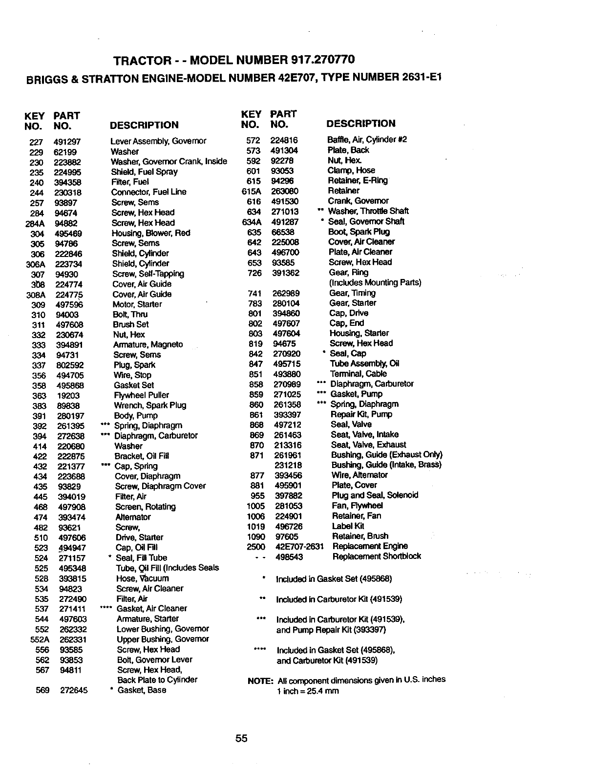
TRACTOR - - MODEL NUMBER 917.270770
BRIGGS & STRATTON ENGINE-MODEL NUMBER 42E707, TYPE NUMBER 2631-E1
KEY PART KEY PART
NO. NO. DESCRIPTION NO. NO. DESCRIPTION
227 491297 LeverAssembly, Governor 572 224816 Baffle,Air' Cylinder#2
229 62199 Washer 573 491304 Plate, Back
230 223882 Washer,Governor Crank, Inside 592 92278 Nut, Hex.
235 224995 Shield, Fuel Spray 601 93053 Clamp, Hose
240 394358 Filter,Fuel 615 94296 Retainer, E-Ring
244 230318 Connector,Fuel Line 615A 263080 Retainer
257 93897 Screw, Seres 616 491530 Crank, Govemor
284 94674 Screw, Hex Head 634 271013 ** Washer,Throttle Shaft
284A 94882 Screw, Hex Head 634A 491287 * Seal, GovernorShaft
304 495469 Housing,Blower,Red 635 66538 Boot, Spark Plug
305 94786 Screw, Seres 642 225008 Cove_,Air Cleaner
306 222846 Shield, Cylinder 643 496700 Plate, Air Cleaner
306A 223734 Shield, Cylinder 653 93585 Screw, Hex Head
307 94930 Screw, Self-Tapping 726 391362 Gear, Ring
31_8 224774 Cover,AirGuide (Includes MountingParts)
308A 22477,5 Cover,AirGuide 741 262989 Gear, Timing
309 497596 Motor,Starter 783 280104 Gear, Starter
310 94003 Bolt,Thru 801 394860 Cap, Drive
311 497608 BrushSet 802 497607 Cap, End
332 230674 Nut, Hex 803 497604 Housing, Starter
333 394891 Armature,Magneto 819 94675 Screw, Hex Head
334 94731 Screw, Seres 842 270920 * Seal, Cap
337 802592 Plug, Spark 847 495715 Tube Aseamb_f,Oil
356 494705 Wire, Stop 851 493880 Terminal,Cable
358 495868 Gasket Set 858 270989 "*" Diaphragm,Carburetor
353 19203 Rywheel Puller 859 271025 "" Gasket, Pump
383 89838 Wrench,Spark Plug 860 261358 *** Spdng, Diaphragm
391 280197 Body,Pump 861 393397 Repair Kit,Pump
392 261395 "** Spdng,Diaphragm 868 497212 Seal, Valve
394 272638 "Diaphragm,Carburetor 869 261463 Seat, Valve, Intake
414 220680 Washer 870 213316 Seat, Valve, Exhaust
422 222875 Bracket.Oil Fill 871 261961 Bushing,Guide (F.shaustOnly)
432 221377 "Cap, Spring 231218 Bushing,Guide (Intake,Brass)
434 223688 Cover.Diaphragm 877 393456 Wire, Alternator
435 93829 Screw, Diaphragm Cover 881 495901 Plate, Cover
445 394019 Filter,Air 955 397882 Plug and Seal, Solenoid
468 497908 Screen, Rotating 1005 281053 Fan, Fiywheal
474 393474 Alternator 1006 224901 Retainer, Fan
482 93621 Screw, 1019 496726 Label Kit
510 497606 Drive, Starter 1090 97605 Retainer,Brush
523 494947 Cap, Oil Fill 2500 42E707-2631 Replacement Engine
524 271157 * Seal, FdlTube - -498543 Replacement Shortbiock
525 495348 Tube, 0il Fill (includesSeals
528 393815 Hcee, '_acuum Includedin Gasket Set (495868)
534 94823 Screw, AirCleaner
535 272490 Fdter,Air *" Includedin CarburetorKit (491539)
537 271411 .... Gasket,AirCleaner
544 497603 Armature, Starter "" Includedin CarburetorKit (491539),
552 262332 Lower Bushing,Governor and Pump Repair Kit (393397)
552A 262331 Upper Bushing, Governor
556 93585 Screw, Hex Head .... Includedin Gasket Set (495868),
562 93853 Bolt,GovernorLever and CarburetorKit (491539)
567 94811 Screw, Hex Head,
Back Plateto Cylinder NOTE: AI_componentdimensior,sgivenin U.S. Inches
569 272645 * Gasket, Base 1 inch= 25.4 mm
55

56

57

58

SUGGESTED GUIDE FOR SIGHTING SLOPES FOR SAFE OPERATION
"T -.-- .,,.,.
I ""
SIGHTING
GUIDE
ONLY RIDE UP AND DOWN HILL,
NOT ACROSS HILL
ol
_D
15" MAX.
I
Operate your Tractor up and down the face of slopes (not I
greater than 15°), never across the face. Make turns gradu- f
ally to prevent tipping or loss of control, Exercise extreme
ceutlon when changing direction on elopes.

Forthe repairor replacementpartsyouneed
delivereddirectlyto your home
•Call 7 am - 7 pm, 7 days a week
1-800-366-PART
(1-800-366-7278)
Para ordenar piezas con entrega a
domlcilio - 1-800-659-7084
For in-house major brand repair service
Call 24 hours a day, 7 days a week
1-800-4-REPAIR
(1-800-473-7274)
Para pedir servicio de reparaci6n a
domicilio - 1-800-676-5811
For the location of a Sears Parts and
Repair Center in your area
Call 24 hours aday, 7 days a week
1-800-488-1222
For information on pumhasing a Sears
Maintenance Agreement or to inquire
about an existing Agreement
Call 9 am - 5 pm, Monday-Saturday
1-800-827-6655
mmmmmm
mmmmnm
When requesting service_ or ordering
parts, always provide the_following
information:
•Product Type •Part Number
• Model Number •Part Deecdption
SEARS
Amenca's Repaor Specialists
166691 11.2.98 SV Printed in U.S.A.
