Craftsman 917 272233 Users Manual
917272233 917272233 CRAFTSMAN LAWN TRACTOR - Manuals and Guides L0105087 View the owners manual for your CRAFTSMAN LAWN TRACTOR #917272233. Home:Lawn & Garden Parts:Craftsman Parts:Craftsman LAWN TRACTOR Manual
CRAFTSMAN Lawn, Tractor Manual L0105087 CRAFTSMAN Lawn, Tractor Owner's Manual, CRAFTSMAN Lawn, Tractor installation guides
917.272233 L0105087
2015-01-05
: Craftsman Craftsman-917-272233-Users-Manual-160781 craftsman-917-272233-users-manual-160781 craftsman pdf
Open the PDF directly: View PDF ![]() .
.
Page Count: 60

Owner's Manual
ICRRFTSMRN°[
20 HP
ELECTRIC START
48" MOWER
6 SPEED TRANSAXLE
LAWN TRACTOR
Model No.
917.272233
•Safety
•Assembly
•Operation
•Maintenance
•Repair Parts
CAUTION:
Read and follow all
Safety Rules and Instructions
before operating this equip-
ment.
For answers to your questions
about this product, Call:
1-800-659-5917
Sears Craftsman Help Line
5 am -5 pm, Mon -Sat
Sears, Roebuck and Co., Hoffman Estates, IL 60179
Visit our Craftsman website: www.sears.com/craftsman
Warranty ............................................... 2
Safety Rules ......................................... 3
Product Specifications .......................... 6
Assembly .............................................. 8
Operation ............................................ 12
Maintenance Schedule ...................... 18
Maintenance ....................................... 18
Service and Adjustments.................... 22
Storage ............................................... 29
Troubleshooting ................................. 30
Repair Parts ........................................ 34
Pads Ordering ..................... Back Cover
LIMITEDTWOYEAR WARRANTY ON CRAFTSMAN RIDING EQUIPMENT PARTS
For two (2) years from the date of purchase, if this Craftsman Riding Equipment is
maintained, lubricated and tuned up according to the instructionsin the owner's
manual, Sears will repair or replace, free of charge, any parts found to be defective in
matedal or workmanship. Warranty service is available free of charge by retuming your
Craftsman riding equipment to your nearest Sears Service Center. In-home warranty
service is available but atrip charge will apply. This warranty applies only while this
productis in the United States.
This Warranty does not cover:.
•Expendable items which become worn dudng normal use, such as blades, spark
plugs, air cleaners, belts and oil filters.
•Tire replacement or repair caused by punctures from outside objects, such as nails,
thorns, stumps, or glass.
•Repairs necessary because of operator abuse, including but not limited to, damage
caused by towing objects beyond the capability of the dding equipment, impacting
objectsthat bend the frame or crankshaft, or over speeding the engine.
•Repairs necessary because of operator negligence, including but not limited to,
electrical and mechanical damage caused by improper storage, failure to use the
proper grade and amount of engine oil, failure to keep the deck clear of flammable
debds, or the failure to maintain the equipment according to the instructionscon-
tained in the owner's manual.
•Engine (fuel system) cleaning or repairs caused by fuel determined to be contami-
nated or oxidized (stale). In general, fuel should be used within thirty (30) days of its
purchase date.
•Riding equipment used for commercial or rental purposes. A product is "used for
commercial purpose" if is used for any purpose other than single family household
dwellings or in usage where profit is made.
LIMITED 90 DAYWARRANTY ON BATrERY
For ninety (90) days from date of purchase, if any battery included with this riding
equipment proves defective in material or workmanship and our testing determines the
battery will not hold acharge, Sears will replace the battery at no charge. Warranty
service is available free of charge by returning your Craftsman ddingequipment to
your nearest Sears Service Center. In-home warranty service is available but a trip
charge will apply.This warranty applies only while this product is in the United States.
TO LOCATE THE NEAREST SEARS SERVICE CENTER OR TO SCHEDULE IN-HOME
WARRANTY SERVICE, SIMPLY CONTACT SEARS AT 1-8004-MY-HOME
This Warranty gives you specific legal dghts, and you may also have other nghts which
may vary from state to state.
Sears, Roebuck and Co., D/817 WA, Hoffman Estates, IL 60179
2
IMPORTANT: This curling mach ne s capabe of amputating hands and feet and
throwingobjects. Failure to observe the followingsafety instructions could result in
serious injuryor death.
I. GENERAL OPERATION
•Read, understand, and follow all
instructionsin the manual and on the
machine before starting.
•Onl_ allow responsible adults, who are
famdiar with the instructions,to operate
the machine.
• Clear the area of objects such as
rocks, toys, wire, etc. which could be
picked up and thrown by the blade.
•Be Sure the area is clear of other
i_ople before mowing. Stop machine
if anyone enters the area.
Never carry passengers.
Do not mow in reverse unless abso-
utely necessary, h3ways look down
and behind before and while back ng.
•Be aware of the mower discharge
direction and do not point it at anyone.
DO not operate the mower without
either the entire grass catcher or the
guard in place.
_•Slow down before turning.
Never leave e running machine
unattended. /dways turn off blades, set
parking brake stop engine, and
remove keys before dismounting.
Turn off btades when not mowing.
•Stop engine before removing grass
catcher or unclogging chute.
•Mow only in daylight or good artificia|
light.
•Do not operate the machine while
under the inftuance ol alcohol or dru_s.
•Watch for traffic when operating near or
crossing roadways.
•Use extra care when loading or
unloading the machine into a trailer or
truck.
•Data indicates that operators, age 60
years and above, are involved in a
large percentage of riding mower-
related inufies. These olj)erators
should evaluate the r abihty to operate
the riding mower safely enough to
protect t.hemselves and others from
senous injury.
•Keep machine free of grass, leaves or
other debris build-up which can touch
hot exhaust /engine parts and burn.
Do not allow the mower deck to plow
leaves or other debris which can cause
build-up to occur. Clean any oil or fuel
spillage before operating or storing the
machine. Allow machine to cool before
storage.
I|. SLOPE OPERATION
S opes are a major factor related to loss-of-
control and tipever accidents, wh ch can
result in severe in ury or death. At| stopes
require extra caution. Ifyou cannot back up
the slope or if you feel uneasy on it, do not
mow it.
DO*.
•Mow up and down slopes, not across.
•Remove obstacles such as rocks, tree
limbs, etc.
• Watch for ho|es, ruts, or bumps.
Uneven terrain could overturn the
machine. Tall grass can hide ob-
stacles.
•Use slow speed. Choose a low gear
so that you will not have to stop or shift
while on the slope.
•Follow the manufacturer's recommen-
dations for wheel weights or counter-
weights to improve stability.
•Usa extra care with grass catchers or
other attachments. These can change
the stability of the machine.
•Keep all movement on the slopes slow
and gradual Do not make sudden
changes in speed or direction.
•Avoid starting or stopping on aslope. If
tires lose traction, disengage the
blades and proceed slowly straight
down the slope.
DO NOT:
•Do not turn on slopes untsss neces-
sary, and then, turn slowly and gradu-
ally downhill, if possible.
• Do not mow near dmp-offs, ditches, or
embankments. The mower could
suddenly turn over if e wheel is over
the edge of acliff or ditch, or ifan edge
caves in.
•Do not mow on wet grass. Reduced
traction could cause sliding.
• Do not try to stabitize the machine by
putting your foot on the ground.
•Do not use grass catcher on steep
slopes.
IlL CHILDREN
Tragic accidents can occur if the operator
is not alert to the presence of children.
Children are often attracted to the
machine and the mowing activity. Never
assume that children will remain where
you last saw them.
•Keep children out of the mowing area
and under the watchful care of another
responsible adult.
• Be alert and turn machine olt if children
enter the area.
•Before and when backing, look behind
and down for small children.
• Never cerry children. They may fall off
and be seriously injured or interfere
with safe machine operation.
•Never allow children to operate the
machine.
•Use extra care when approaching bSnd
corners, shrubs, trees, or other objects
that may obscure vision.
IV. SERVICE
• Use extra care in handling gasoline
and other fuels. They are flammable
end vapors are explosive.
-Use only an approved container.
-Never remove gas cap or add fuel
with the engine running. Allow
engine to cool before refueling. Do
not smoke.
-Never refuel the machine indoors.
- Never store the machine or fuel
container inside where there is an
open flame, such as a water heater.
•Never run a machine inside a closed
area.
•Keep nuts and bolts, especially blade
attachment bolts, tight and keep
equipment in good condition.
•Never tamper with safety devices.
Check their proper operation regularly.
•Keep machine free of grass, leaves, or
other debris build-up. Clean oil or fuel
spillage. Allow machine to cool before
storing.
•Stop and inspect the equipment if you
strike an object. Repair, if necessary,
before restarting.
•Never make adjustments or repairs
with the engine running.
•Grass catcher components are subject
to wear, damage, and deterioration,
which could expose moving parts or
allow objects to be thrown. Frequently
check components and replace with
manufacturer's recommended parts,
when necessary.
•Mower blades are sharp and can cut.
Wrap the blade(s) or wear gloves, and
use extra caution when servicing them.
•Check brake operation frequently.
Adjust and service as required.
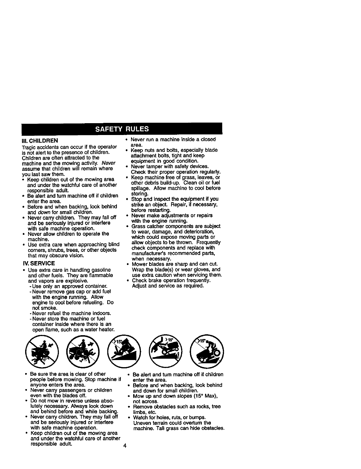
• Be sure the area is clear of other
people before mowing. Stop machine if
anyone enters the area.
•Never carry passengers or children
even with the blades off.
•Do not mow in reverse unless abso-
lutely necessary. Always look down
and behind before and while backing.
•Never carry children. They may fall off
and be seriously injured or interfere
with safe machine operation.
•Keep children out of the mowing area
and under the watchful care ol another
responsible adult.
•Be alert and turn machine off if children
enter the area.
•Before and when backing, look behind
and down for smal_ children.
•Mow up and down slopes (15° Max),
not across.
•Remove obstacles such as rocks, tree
limbs, etc.
•Watch for holes, ruts, or bumps.
Uneven terrain could overturn the
machine. Tall grass can hide obstacles.
•Use slow speed. Choose a low gear so
that you will not have to stop or shift
while on the slope.
•Avoid starting or stopping on aslope. If
tires lose traction, disengage the
blades and proceed slowly straight
down the slope.
•If machine stops while going uphill,
disengage blades, shift into reverse
and back down slowly.
• Do not turn on slopes unless neces-
sap/, and then, turn slowly and gradu-
ally downhill, if possible.
_Look for this symbol to point out
importantsafety precautions. It means
CAUTION!II BECOME ALERT!I! YOUR
SAFETY IS INVOLVED.
ACABTION: In order to prevent acciden-
tal starting when setting up, transporting,
adjusting or making repairs, always
disconnect spark plug wire and place
wire where it cannot contact spark plug.
ACAUTION: Do not coast down a hill in
neutral,you may lose control of the
tractor.
ACAUTION: Tow only the attachments
that are recommended by and comply
with specifications of the manufacturer of
your tractor. Use common sense when
towing. Operate only at the lowest
possible speed when on aslope. Too
heavy of aload, while on a slope, is
dangerous. Tires can lose traction with
the ground and cause you to lose control
of your tractor.
A, WARNING: Engine exhaust some of its
constituents, and certain vehicle compo-
nents contain or emit chemicals known to
the State of California to cause cancer
and birth defects or other reproductive
harm.
AWARNING: Battery posts terminals and
re ated accessories conta n ead and ead
compounds, chemicals known to the State
of Califomia to cause cancer and birth
defects or other reproductive harm. Wash
hands after handUng.
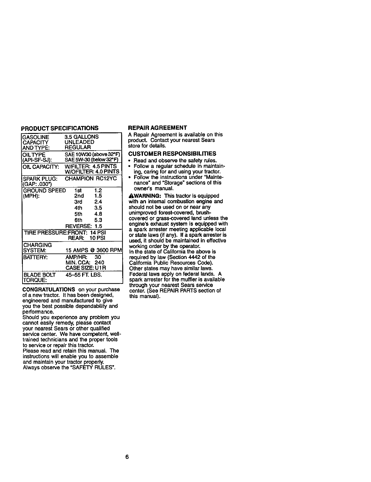
PRODUCTSPECIFICATIONS
SASOLINE 3,5 GALLONS
CAPACITY UNLEADED
ANDTYPE: REGULAR
OILTYPE SAE 10w30 (above32=F)
IAPI-SF-SJ): SAE5W-30 Ibelow 32_F)
OIL CAPACITY: W/FILTER: 4.5 PINTS
W/OFILTER: 4.0 PINTS
SPARK PLUG: CHAMPION RC12YC
SAP: .030")
GROUND SPEED 1st 1.2
(MPH): 2nd 1.5
3rd 2.4
4th 3.5
5th 4.8
6th 5,3
REVERSE: 1.5
TIRE PRESSURE:FRONT: 14 PSI
REAR: 10 PSi
CHARGING
SYSTEM: 15 AMPS @3600 RPM
BATTERY: AMP/HR: 30
MIN. CCA: 240
CASE SIZE: U 1R
BLADE BOLT 45-55 F"ELBS.
I'ORQUE:
CONGRATULATIONS on your purchase
of anew tractor. It has been designed,
engineered and manufactured to give
you the best possible dependability and
performance.
Should you experience any problem you
cannot easily remedy, please contact
your nearest Seem or other qualified
service center. We have competent, well-
trained technicians and the proper tools
to service or repair this tractor.
Please read and retain this manual. The
instructionswilt enable you to assemble
and maintain your tractor properly.
Always observe the "SAFETY RULES".
REPAIR AGREEMENT
A Repair Agreement is available on this
product. Contact your nearest Sears
store for details.
CUSTOMER RESPONSIBILITIES
•Read and observe the safety rules.
•Follow a regular schedule in maintain-
ing, caring for and using your tractor.
•Follow the instructionsunder "Mainte-
nance_and "Storage" sections of this
owner's manual.
_I_WARNING: This tractor is equipped
with an internal combustion engine and
should not be used on or near any
unimproved forest-covered, brush-
covered or grass-covered land unless the
engine's exhaust system is equipped with
aspark arrester meeting applicable local
or state laws (if any). If a spark arrester is
used, it should be maintained in effective
working order by the operator.
In the state of California the above is
required by law (Section 4442 of the
California Public Resources Code).
Other states may have similar laws.
Federal laws apply on federal lends. A
spark arrester for the muffler is available
through your nearest Sears service
center. (See REPAIR PARTS section of
this manual).
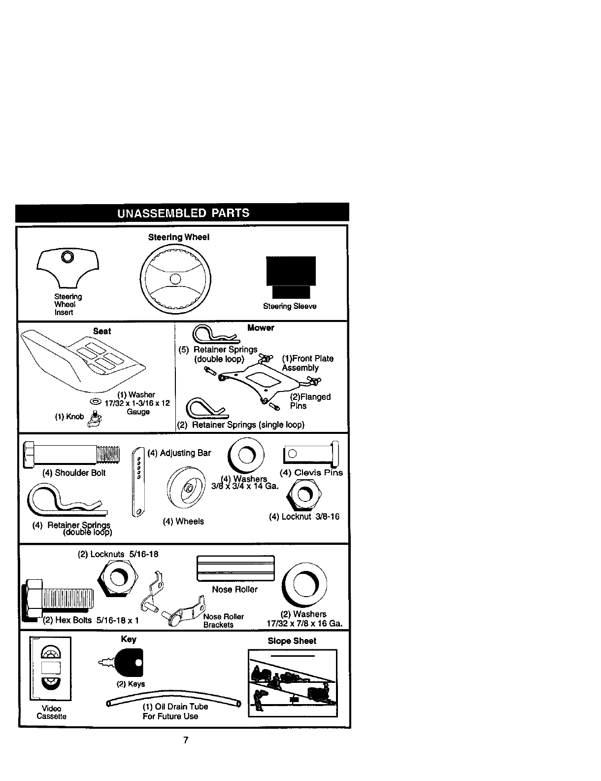
SteeringWheel
SteedrN
Steeiing Sleeve
_her
17/32x 1-3/16x 12
(1) Knob_Gauge
(4) Shoulder Bolt
(4) Retainer Sodnas
(doubl6 Io6"p)
Mower
(5) Retainer Springs
(double loop) - _(1)Front Plate
_(2)Flanged
--_ Pins
(2) Retainer Springs (single loop)
i(4) AdjustingBar _ L _
' _ 3/_4x)3_she_SG a (4_ Pins
O_ (4) Wheels (4) Locknut 3/8-16
(2) Locknuts 5/16-18
-- _ _ _Nose Relier
I/lllll]lnlbllllLIIIIbllLI1....
=r (2) Hex Bolts rD-lU X1 _ Brackets
(2)Washers
17/32x 7/8 x 16 Ga.
Key Slope Sheet '
Video
Cassette ForFuture Use
7
Your new tractor has been assembled at the factory with exception of those parts left
unassembled for shipping purposes. To ensure safe and proper operation of your
tractor all parts and hardware you assemble must be tightened securely. Use the
correct tools as necessary to insure proper tightness. Review the video cassette before
you begin.
TOOLS REQUIRED FOR ASSEMBLY
A socket wrench set will make assembly
easier. Standard wrench sizes you need
are listed below.
(1) 9/16" Wrench (1) 3/4" Socket w/
(1) 1/2" wrench ddve ratchet
(1) Utility knife (1) Pliers
(1) Tire pressure gauge
When right or left hand is mentioned in
this manual, it means, from your point of
view, when you are in the operating
position (seated behind the steering
wheel).
TO REMOVETRACTOR FROM
CARTON
UNPACK CARTON
1. Remove all accessible loose parts
and parts boxes from shipping carton.
2. Cut, from top to bottom, along lines on
all four corners of shipping carton, and
lay panels flat.
3. Remove mower and package materi-
als.
4. Check for any additional loose parts
or boxes and remove.
BEFORE REMOVINGTRACTOR
FROM SKID
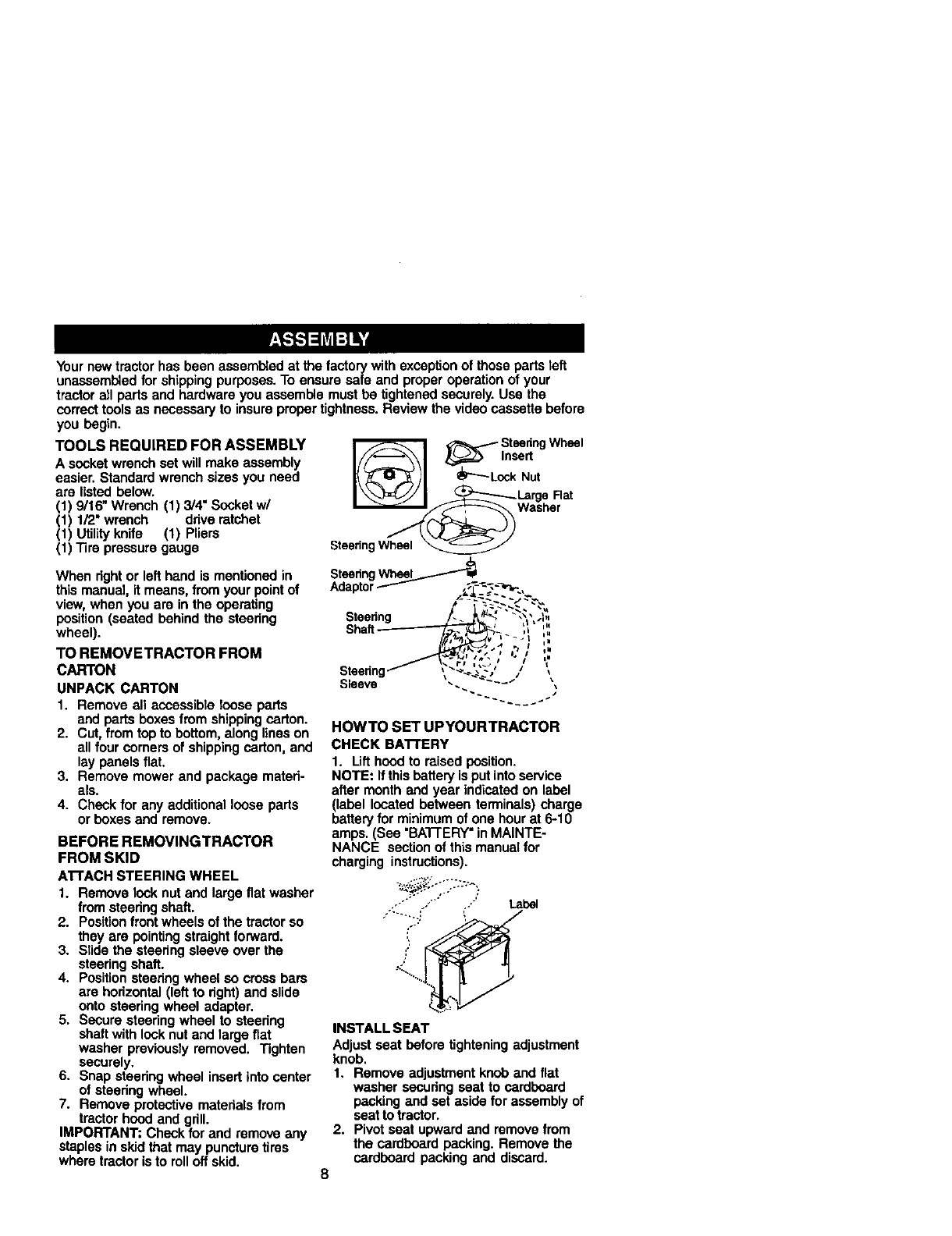
A'I-rACH STEERING WHEEL
1. Remove look nut and large flat washer
fromsteering shaft.
2. Position front wheels of the tractor so
they are pointing straight forward.
3. Slide the steering sleeve over the
steering shaft.
4. Position steering wheel so cross bars
are hodzontal (left to right) and slide
onto steering wheel adaptor.
5. Secure steering wheel to steering
shaft with lock nut and large flat
washer previously removed. Tighten
securely.
6. Snap steering wheel insert into center
of steering wheel.
7. Remove protective materials from
tractor hood and grill.
IMPORTANT: Check for and remove any
staples in skid that may puncture tires
where tractor is to roll off skid.
_SteeringWheel
IIn ert
I/ /I Nut
SteeringWheel
SteeringWh_l_
Adaptor_
Shaff--__ ,L ,,
Sleeve ... -
HOWTO SET UPYOURTRACTOR
CHECK BA'I'rERY
1. Lift hood to raised position.
NOTE: Ifthis battery is put intoservice
after month and year indicated on label
(label located between terminals) charge
battery for minimum of one hour at 6-10
amps. (See "BA'I-FERY"inMAINTE-
NANCE section of this manual for
charging instructions).
_:'_;"i.-" "-_^:"
/o.. Label
INSTALL SEAT
Adjust seat before tightening adjustment
knob.
1, Remove adjustment knob and flat
washer securing seat to cardboard
packing and set aside for assembly of
seat to tractor.
2. Pivot seat upward and remove from
the cardboard packing. Remove the
cardboard packing and discard.
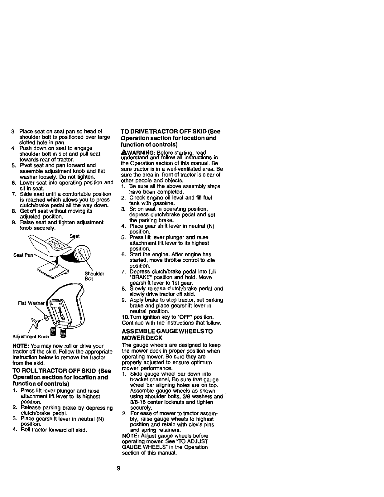
3. Placeseatonseatpansoheadof
shoulder bolt is positioned over large
slotted hole in pen.
4. Push down on seat to engage
shoulder bolt in slot and pull seat
towards rear of tractor.
5. Pivot seat end pan forward and
assemble adjustment knob and flat
washer loosely. Do not tighten.
6. Lower seat into operating position and
sitin seat.
7. Slide seat until acomfortable position
is reached which allows you to press
clutch/brake pedal all the way down.
8. Get off seat without moving its
adjusted position.
9. Raise seat and tighten adjustment
knob securely.
SeatPan-__
_. /_ Shoulder
Bo_t
Rat Washe.,__"
NOTE: You may now roll or drive your
tractor off the skid. Follow the appropdate
instructionbelow to remove the tractor
from the skid.
TO ROLLTRACTOR OFF SKID (See
Operation section for location and
function of controls)
1. Press liftlever plunger end raise
attachment lift lever to its highest
position.
2. Release parking brake by depressing
clutch/brake pedal.
3. Place gearshift lever in neutral (N)
position.
4. Roll tractor forward off skid.
TO DRIVETRACTOR OFF SKID (See
Operation section for location and
function of controls)
_I,WARNING: Before starting, read,
understand and follow all instructions in
the Operation section of this manual. Be
sure tractor is in ewell-ventilated area. Be
sure the area in front of tractor is clear of
other people and objects.
1. Be sure all the above assembly steps
have been completed.
2. Check engine oil level and fill fuel
tank with gasoline.
3. Sit on seat in operating position,
depress clutch/brake pedal and set
the parking brake.
4. Place gear shift lever in neutral (N)
position.
5. Press lift lever plunger end raise
attachment lift lever to its highest
position.
6. Start the engine. After engine has
started, move throttle control to idle
position.
7. Depress clutch/brake pedal into full
"BRAKE" pos_on and hold. Move
gearshift lever to 1st gear.
8. Slowly release clutch/brake pedal end
slowly ddve tractor off skid.
9. Apply brake to stop tractor, set parking
brake and place gearshift lever in
neutral position.
10.Turn ignition key to "OFF" position.
Continue with the instructions that follow.
ASSEMBLE GAUGEWHEELSTO
MOWER DECK
The gauge wheels are designed to keep
the mower deck in proper positionwhen
operating mower. Be sure they are
propedy adjusted to ensure optimum
mower performance.
1. Slide gauge wheel bar down into
bracket channel, Be sure that gauge
wheel bar aligning holes are on top.
Assemble gauge wheels as shown
using shoulder bolts, 3/8 washers and
3/8-16 center Iocknuts and tighten
securely.
2. For ease of mower to tractor assem-
bly, raise gauge wheels to highest
position and retain with clevis pins
and spring retainers.
NOTE: Adjust gauge wheels before
operating mower. See "1"OADJUST
GAUGE WHEELS" in the Operation
section of this manual.
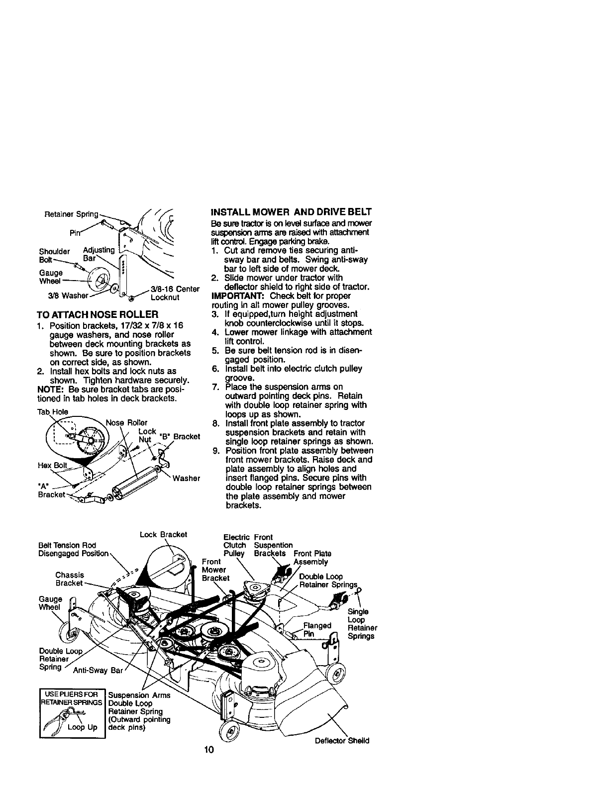
TOATTACHNOSEROLLER
1. Positionbrackets,17/32x7/8x16
gaugewashers,andnoseroller
betweendeckmountingbracketsas
shown.Besuretopositionbrackets
oncorrectside,as shown.
2. Install hex bolts and look nuts as
shown. Tighten hardware securely.
NOTE: Be sure bracket tabs are posi-
tioned in tab holes in deck brackets.
TabHole
_Nose Roller
Lock , .
(i'_ ._'_ Nut B Bracket
• Was,ar
INSTALL MOWER AND DRIVE BELT
Be suretractorison leve_surfaceand mower
su_ arms are _withattachment
liftcontrol.Engageparkingbrake.
1. Cut and remove ties securing anti-
sway bar and belts. Swing anti-sway
bar to left side of mower deck.
2. Slide mower under tractor with
deflector shield to fight side of tractor.
IMPORTANT: Check belt for proper
routing in all mower pulley grooves.
3. If equipped,turn height adjustment
knob counterclockwise until it stops.
4. Lower mower linkage with attachment
liftcontrol.
5. Be sure belt tension rod is in disen-
gaged position.
6. Install belt into electric clutch pulley
groove.
7. Place the suspension arms on
outward pointing deck pins. Retain
with double loop retainer spring with
loops up as shown.
8. Installfront plate assembly to tractor
suspension brackets and retain with
single loop retainer springs as shown.
9. Position front plate assembly between
front mower brackets. Raise deck and
plate assembly to align holes and
insert flanged pins. Secure pins with
double loop retainer springs between
the plate assembly and mower
brackets.
Belt Tension Rod
Lock Bracket
Chassis
Gauge
Wheel
Double
Sprin Anti-Sway Ba
USEPUERSFOR Suspension Arms
RETAINER SPRINGS Doub e Loop
j_ Retainer Spdng
//_F. \(Outward pointing
,_ jLoop Up deck pins)
Electric Front
Clutch Suspention
Pulley Brackets Front Plate
Front
Mower
Bracket _
10
Single
Loop
Retainer
Spdngs
Deflector Sheild
NOTE: To assist in locating hole in
flanged pin, the hole in pin is inline with
notchon head of pin. If necessary, move
mower side-to-side to give space
between plate and mower brackets.
IMPORTANT: Check belt for proper
routing in all mower pulley grooves.
10. Engage belt tension rod by pushing
rod into looking bracket.
_CAUTION: Belt tension rod is spring
loaded. Have atight grip on rod and
engage slowly.
11.Connect anti-sway bar to chassis
bracket under left footrestand retain
with double loop retainer spring.
12.If equipped, turn height adjustment
knob clockwise to remove slack from
mower suspension.
13. Raise deck to highest position.
14.Adjust gauge wheels before operating
mower as shown in the Operation
section of this manual.
CHECK TIRE PRESSURE
The tireson your tractorwere ovednflatod
at the factory for shippingpurposes.
Correct tire pressureis important for best
cutting performance.
•Reduce tire pressureto PSi shown in
=PRODUCT SPECIFICATIONS" section
of this manual.
CHECK MOWER LEVELNESS
For best cutting results,mower should be
properlyleveled. See "TO LEVEL MOWER
HOUSING" in the Serv;ce and Adjustments
section of this manual.
CHECK FOR PROPER PosmoN OF ALL
BELTS
See the figures that are shown for replac-
ing motion,mower drive, and mower blade
drive belts inthe Service and Adjustments
sectionof thismanual. Verifythat the belts
are routed correctly.
CHECK BRAKE SYSTEM
After you learn howto operate yourtractor,
check to see that the brake is propedy
adjusted. See "TO ADJUST BRAKE"inthe
Service and Adjustmentssectionof this
manual.
o/CHECKLIST
Before you operate and enjoy your new
tractor, we wish to assure that you receive
the best performance and satisfaction
from this quality product.
Please review the following checklist:
/All assembly instructions have been
completed.
v"No remaining loose parts in carton.
/Battery is properly prepared and
charged.(Minimum 1 hour at 6 amps).
,/Seat is adjusted comfortably and
tightened securely.
/All tires are properly inflated. (For
shipping purposes, the tires were
overinflated at the factory).
/Be sure mower deck is properly leveled
side-fo-side/front-to-rear for best cutting
results. (Tires must be properly inflated
for leveling).
#" Check mower and drive belts. Be sure
they are routed property around pulleys
and inside all belt keepers.
,/Check widng. See that all connections
are still secure and wires are properly
clamped.
While learning how to use your tractor,
pay extra attention to the following
important items:
/Engine oil is at proper level.
,/Fuel tank is filled w_thfresh, clean,
regular unleaded gasoline.
/Become familiar with all controls -their
location and function. Operate them
before you start the engine.
/Be sure brake system is in safe
operating condition.
11
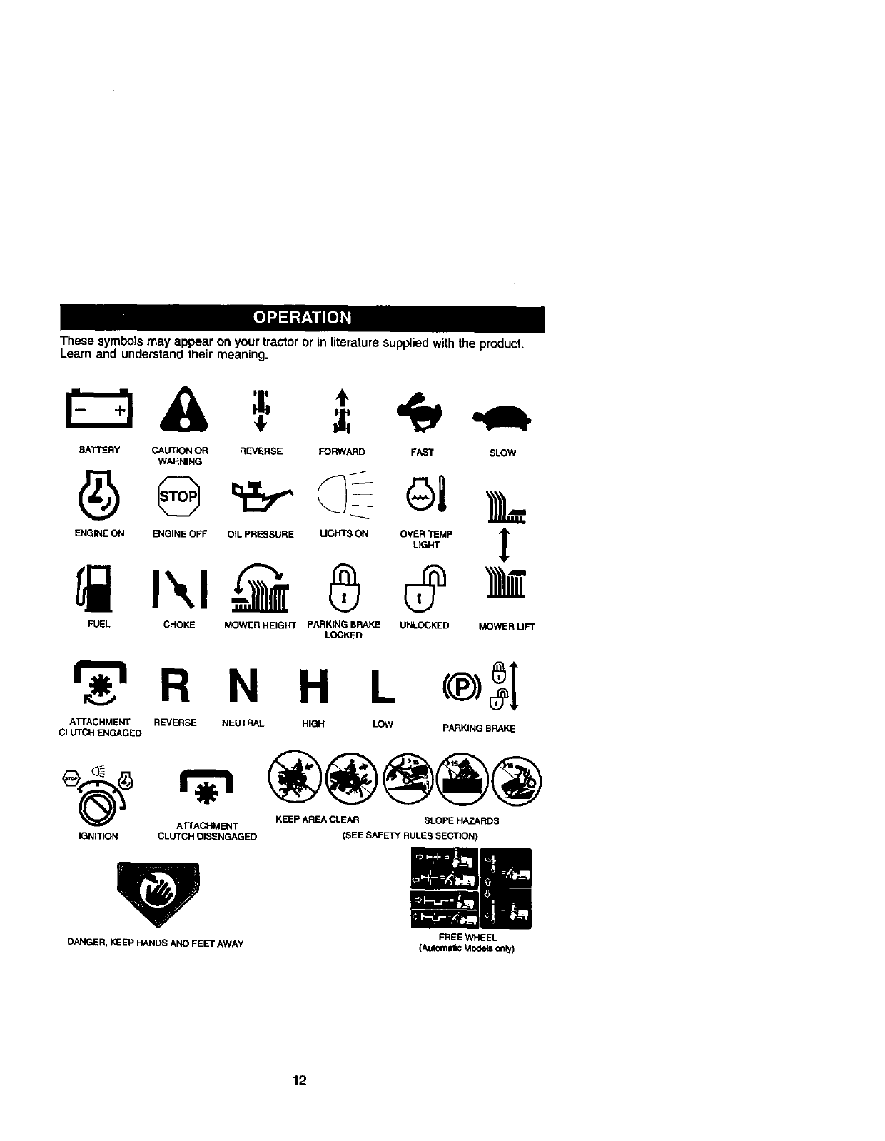
These symbols may appear on your tractor or in literature suppliedwith the product.
Learn and understand their meaning.
BATTERY CAUTION OR REVERSE FORWARD FAST SLOW
WARNING
ENGINE ON ENGINE OFF OIL PRESSURE LIGHTS ON OVER TEMP
L_HT
FUEL CHOKE MOWER HEIGHT PARKING BRAKE UNLOCKED
LOCKED MOWER LIFT
_r_'l R N H L
AT[ACHMENT REVERSE NEUTRAL HIGH LOW
CLUTCH ENGAGED
®3I
PARKING BRAKE
ATTACHMENT KEEP AREA CLEAR SLOPE HAZARDS
IGNITION CLUTCH DISENGAGED (SEE SAFEI_( RULES SECTION)
DANGER, KEEp HANDS AND FEET AWAY FREE WHEEL
(AutOmaticModelsonly)
12
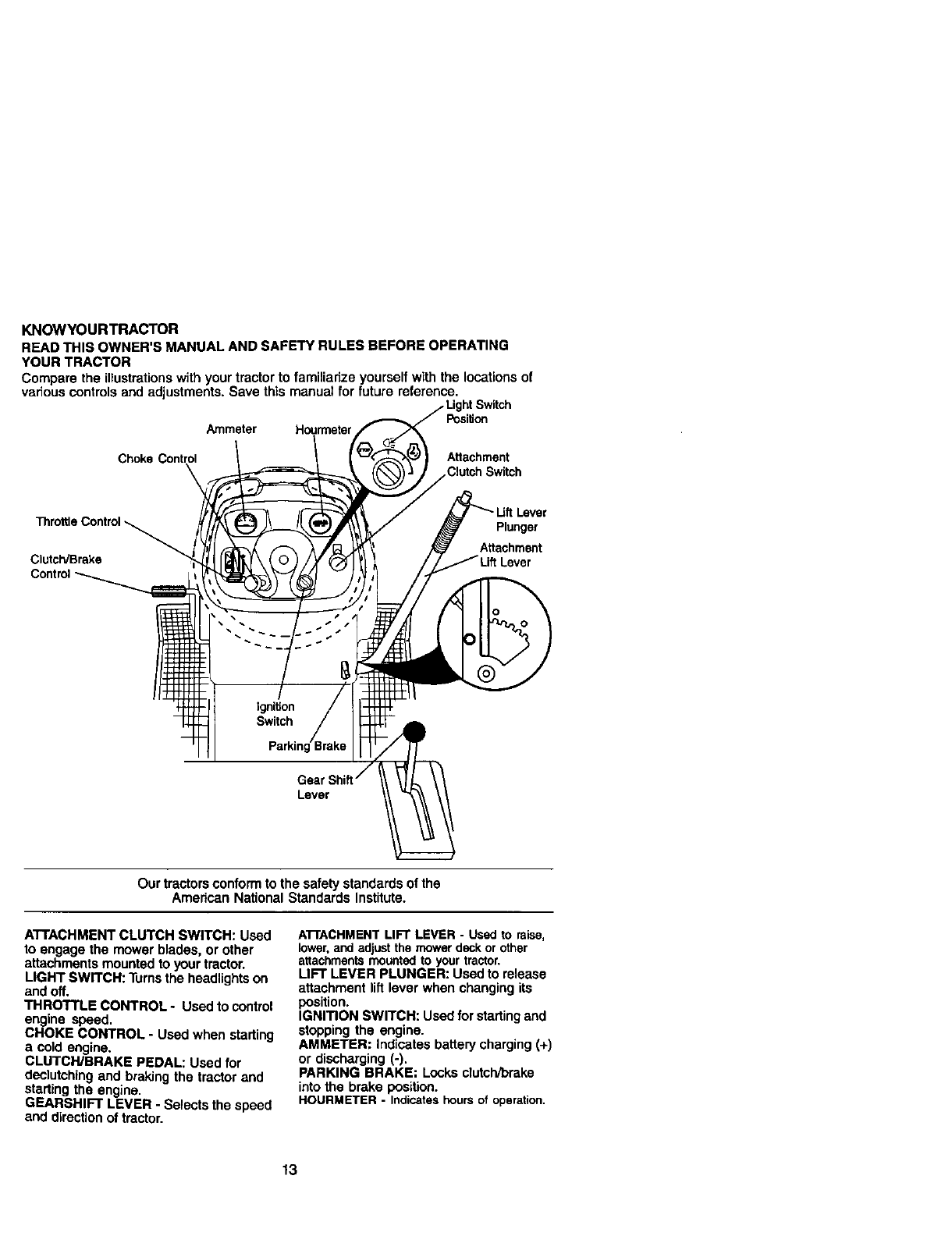
KNOWYOURTRACTOR
READ THIS OWNER'S MANUAL AND SAFETY RULES BEFORE OPERATING
YOUR TRACTOR
Compare the illustrationswith your tractor to familiarize yourself with the locations of
various controlsand adjustments. Save this manual for future reference.
Position
Ammeter Houn'neter
Choke Control Attachment
Clutch Switch
Throttle Control
Clutch/Brake
Lever
Plunger
Attachment
Lever
Our tractors conformto the safety standards of the
American National Standards Institute.
ATTACHMENT CLUTCH SWITCH: Used
to engage the mower blades, or other
attachments mounted to your tractor.
LIGHT SWITCH: Turnsthe headlights on
and off.
THROTTLE CONTROL -Used to control
engine speed.
CHOKE CONTROL -Used when starting
a cold engine.
CLUTCH/BRAKE PEDAL: Used for
declutching and braking the tractor and
starting the engine.
GEARSHIFT LEVER -Selects the speed
and direction of tractor.
A'I-rACHMENTLIFT LEVER -Used to raise,
lower,and adjustthe mowerdeckor other
attachmentsmountedto yourtractor.
LIFT LEVER PLUNGER: Used to release
attachment lift lever when changing its
position.
IGNITION SWITCH: Used for startingand
stopping the engine.
AMMETER: Indicates battery charging (+)
or discharging (-).
PARKING BRAKE: Locks clutch,'brake
into the brake position.
HOURMETER - Indicateshoursof operation.
13
IThe operation of any tractor can result in foreign objects thrown into the
eyes, which can result in severe eye damage. Always wear safety glasses
or eye shields while operating your tractor or performing any adjustments
or repairs. We recommend a wide vision safety mask over spectacles, or
standard safety glasses.
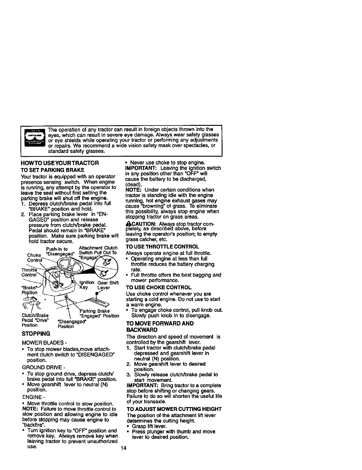
HOWTO USEYOURTRACTOR
TO SET PARKING BRAKE
Your tractor is equipped with an operator
presence sensing switch. When engine
is running,any attempt by the operator to
leave the seat without firstsetting the
parking brake will shut off the engine.
1. Depress clutch/brake pedal into full
=BRAKE" position and hold.
2. Piece parking brake lever in "EN-
GAGED" position and release
pressure from clutch/brake pedal.
Pedal should remain in =BRAKE"
position. Make sure parking brake will
hold tractor secure.
Push-Into AttachmentClutch
C-- =Disengaged" SwitchPullOutTo
noKe =En a e_
_ _ _lgnition Ge_rrShift
=B_ _,_'_:_"_ /3<ey Lever
Clutch/Brake \ =Engaged"Position
Pedal=Drive" "Disengaged"
Position Position
STOPPING
MOWER BLADES -
•To stop mower blades,move attach-
ment clutch switchto "DISENGAGED"
position.
GROUND DRIVE -
•To stop ground drive, depress clutch/
brake pedal into full "BRAKE" position.
•Move gearshift lever to neutral (N)
position.
ENGINE -
•Move throttle controlto slow position.
NOTE: Failure to move throttle control to
slow position and allowing engine to idle
before stopping may cause engine to
"backfire".
•Turn ignition key to "OFF' position and
remove key. Always remove kay when
leaving tractor to prevent unauthorized
use,
• Never use choke to stop engine.
IMPORTANT: Leaving the ignition switch
in any positionother than "OFF" will
cause the battery to be discharged,
(dead).
NOTE: Under certain conditions when
tractor is standing idle with the engine
running, hot engine exhaust gases may
cause =browning"of grass. To eliminate
this possibility,always stop engine when
stoppingtractor on grass areas.
_CAUTION: Always stoptractor com-
pletely, as described above, before
leaving the operator's position; to empty
grass catcher, etc.
TO USE TH RO'I-I'LE CONTROL
Always operate angina at full throttle.
•Operating engine at less than full
throttle reduces the battery charging
rate.
•Full throttle otters the best begging and
mower performance.
TO USE CHOKE CONTROL
Use choke controlwhenever you are
starting a cold engine. Do not use to start
a warm engine.
•To engage choke control, pug knob out.
Slowly push knob in to disengage.
TO MOVE FORWARD AND
BACKWARD
The direction and speed of movement is
controlled by the gearshift lever.
1. Start tractor with clutch/brake pedal
depressed and gearshift lever in
neutral (N) position.
2. Move gearshift lever to desired
position.
3. Slowly release clutch/brake pedal to
start movement.
IMPORTANT: Bringtractor to a complete
stop before shiftingor changing gears.
Failure to do so will shorten the useful life
of your transaxla.
TO ADJUST MOWER CUTTING HEIGHT
The positionof the attachment lift lever
determines the cutting height.
•Grasp liftlever.
•Press plunger with thumb and move
lever to desired position.
14
The cutting height range is approxi-
mately 1-1/2 to 4". The heights are
measured from the ground to the blade
tipwith the engine not running. These
heights are approximate and may vary
depending upon soil conditions, height of
grass and types of grass being mowed.
•The average lawn should be cut to
approximately 2-1/2 inches during the
cool season and to over 3 inches
dudng hot months. For healthier and
better looking lawns, mow often and
after moderate growth.
• For best cutting performance, grass
over 6 inches in height should be
mowed twice. Make the first cut
relatively high; the second to desired
height.
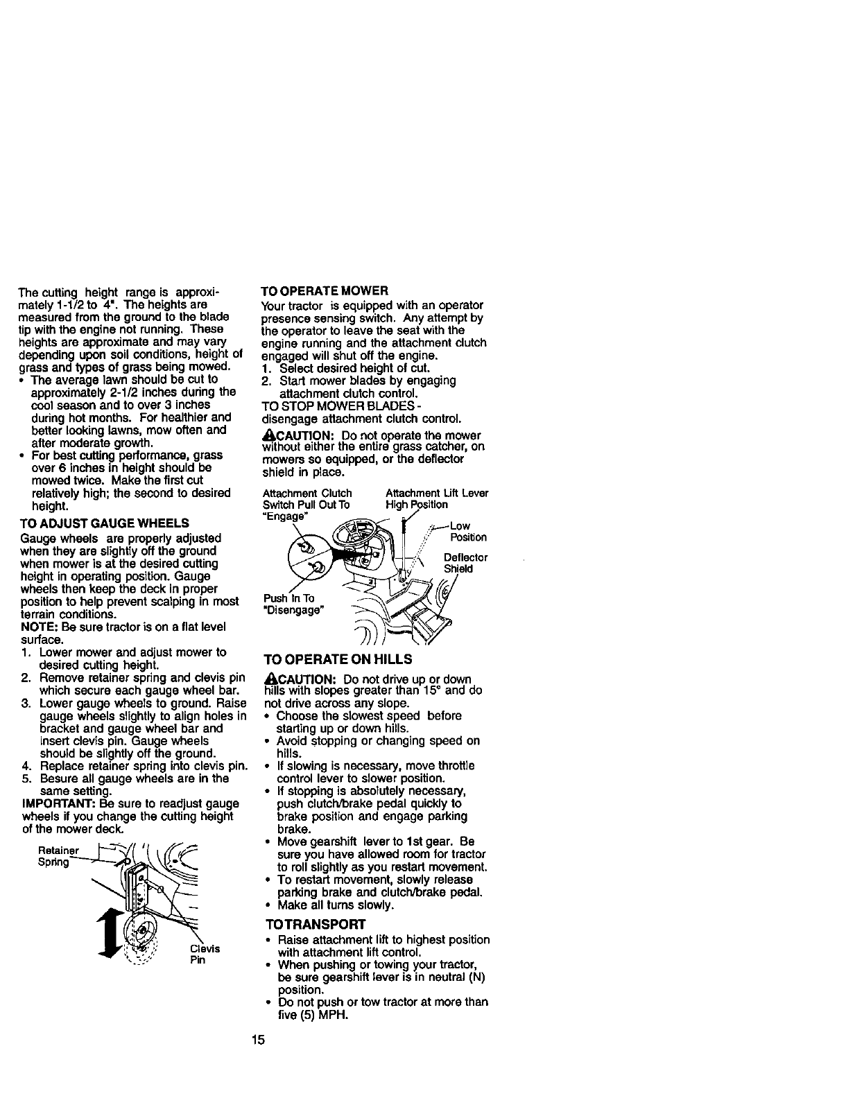
TO ADJUST GAUGE WHEELS
Gauge wheels are propedy adjusted
when they are slightlyoff the ground
when mower is at the desired cutting
height in operating position. Gauge
wheels then keep the deck in proper
positionto help prevent scalping in most
terrain conditions.
NOTE: Be sure tractor is on a flat level
surface.
1. Lower mower and adjust mower to
desired cutting height.
2. Remove retainer spring and clevis pin
which secure each gauge wheel bar.
3. Lower gauge wheels to ground. Raise
gauge wheels slightlyto align holes in
bracket and gauge wheel bar end
insert clevis pin. Gauge wheels
should be slightly off the ground.
4. Replace retainer spring into clevis pin.
5. Besure all gauge wheels ere in the
same setting.
IMPORTANT; Be sure to readjust gauge
wheels if you change the cutting height
of the mower deck.
Spdn!
Clevis
Pin
TO OPERATE MOWER
Yourtractor is equipped with an operator
presence sensing switch. Any attempt by
the operator to leave the seat with the
engine running and the attachment clutch
engaged will shut off the engine.
1. Select desired height of cut.
2. Start mower blades by engaging
attachment clutch control.
TO STOP MOWER BLADES -
disengage attachment clutch control.
_,CAUTION: Do not operate the mower
without either the entire grass catcher, on
mowers so equipped, or the deflector
shield in place.
Attachment Clutch
Switch Pull Out To
"Engage"
Attachment Lift Lever
High Position
Deflector
Shield
PushInTO
"Disengage"
TO OPERATE ON HILLS
A, CAUTION: Do not drive up or down
hills with slopes greater than 15° and do
not drive across any slope.
• Choose the slowest speed before
starting up or down hills.
•Avoid stopping or changing speed on
hills.
•If slowing is necessary, move throttle
control lever to slower position.
•If stopping is absolutely necessary,
push clutch/brake pedal quickly to
brake position and engage parking
brake.
•Move gearshift lever to 1st gear. Be
sure you have allowed room for tractor
to roll slightlyas you restart movement.
•To restart movement, slowly release
parking brake and clutch/brake pedal.
•Make all turns slowly.
TOTRANSPORT
•Raise attachment liftto highest position
with attachment liftcontrol.
•When pushing or towing your tractor,
be sure gearshift lever is in neutral (N)
position.
•Do not push or tow tractor at more than
five (5) MPH.
15
NOTE: To protecthood from damage
when transportingyour tractor on a truck
or a trailer, be sure hood is closed and
secured to tractor. Use an appropriate
means of tying hood to tractor (rope, cord,
etc.).
TOWING CARTS AND OTHER AI-FACH-
MENTS
Tow only the attachments that are
recommended by and comply with
specificationsof the manufacturer of your
tractor. Use common sense when towing.
Too heavy of a load, while on aslope, ss
dangerous. Tires can lose traction with
the ground and cause you to lose control
of your tractor.
BEFORE STARTINGTHE ENGINE
CHECK ENGINE OIL LEVEL
The engine in your tractor has been
shipped, from the factory,already filled
with summer weight oil.
1. Check engine oil with tractor on level
ground.
2. Unthread and remove oil flit cap/
dipstick;wipe oil off. Reinsert the
dipstickinto the tube and rest oil fill
cap on the tube. Do not thread the
cap onto the tube. Remove and read
oil level. If necessary, add oil until
"FULL" mark on dipstick is reached.
Do not overfill.
•For cold weather operation you should
change oilfor easier starting(See "OIL
VISCOSITY CHART" in the Mainte-
nance section of this manual).
•To change engine oil, see the Mainte-
nance sectionin this manual.
ADD GASOLINE
•Fill fuel tank. Use fresh, ctean, regular
unleaded gasoline with a minimum of
87 octane. (Use of leaded gasoline will
increase carbon and lead oxide
deposits and reduce valve life). Do not
mix oil with gasoline. Purchase fuel in
quantities that can be used within 30
days to assure fuel freshness.
IMPORTANT: When operating in tem-
peratures below 32°F(0°C), use fresh,
clean winter grade gasoline to help
insure good cold weather starting.
a,_kooWARNING:Experience indicates that
hol blended fuels (called gasohol or
using ethanol or methanol) can attract
moisture which leads to separation and
formation of acids duringstorage. Acidic
gas can damage the fuel system of an
engine while in storage. To avoid engine
problems, the fuel system should be
emptied before storage of 30 days or
longer. Drain the gas tank, start the
engine and let it run untilthe fuel lines
and carburetor are empty. Use fresh fuel
next season. See Storage Instructionsfor
additional information. Never use engine
or carburetor cleaner products in thefuel
tank or permanent damage may occur.
_CAUTION: Fill to bottom of gas tank
filler neck. Do not overfill.Wipe off any
spilled oil or fuel. Do not store, spill or use
gasoline near an open flame.
TO START ENGINE
When starting the engine for the first time
or if the engine has run out of fuel, it will
take extra cranking time to move fuel from
the tank to the engine.
1. Sit on seat in operating position,
depress clutch/brake pedal and set
parking brake.
2. Place gear shift lever in neutral (N)
position.
3. Move attachment clutch to "DISEN-
GAGED" position.
4. Move throttle control to fast position
5. Pull choke control out for a cold
engine start attempt. For a warm
engine start attempt the choke control
may not be needed.
NOTE: Before starting, read the warm and
cold starting procedures below.
6. Insert key into ignition and turn key
clockwise to =START" position and
release key as soon as engine starts.
Do not run starter continuouslyfor
more than fifteen seconds per minute.
If the engine does not start alter
several attempts, push choke control
in, wait a few minutes and try again. If
engine still does not start, pull the
choke control out and retry.
WARM WEATHER STARTING (50°F and
above)
7. When engine starts, slowly push
choke control in untilthe engine
begins to run smoothly. If the engine
starts to run roughly, pull the choke
control out slightlyfor a few seconds
and then continue to push the control
in slowly.
16
•The attachments and ground drive can
now be used. If the engine does not
accept the load, restart the engine and
allow itto warm up for one minute
using the choke as described above.
COLD WEATHER STARTING (50° F and
below)
7. When engine starts, slowly push
choke control in untilthe engine
begins to run smoothly. Continue to
push the choke control in small steps
allowing the engine to accept small
changes in speed and load, untilthe
choke control is fully in. If the engine
starts to run roughly, pull the choke
controlout sn_htlyfor a few seconds
and then continue to push the control
in slowly. This may require an engine
warm-up period from several seconds
to several minutes, depending on the
temperature.
•The attachments can be used during
the engine warm-up period and may
require the choke control be pulled out
slightly.
NOTE: Ifat a highaJtitude(above3000 feet)
orin coldtemperaturss(below32 F) the
carburetor fuel mixturemay need to be
adjustedfor best enginepedormance.See
%0 ADJUST CARBURETOR" in theService
and Adjustmentssectionof thLsmanual.
MOWlNGTIPS
•Mower should be properly leveled for
best mowing performance. See =TO
LEVEL MOWER HOUSING" inthe
Service and Adjustments section of this
manual
•The left hand side of mower should be
used for trimming.
•Drive so that clippings are discharged
onto the area that has been cut. Have
the cut area to the right of the tractor.
This will result in a more even distribu-
tion of clippingsand more uniform
cutting.
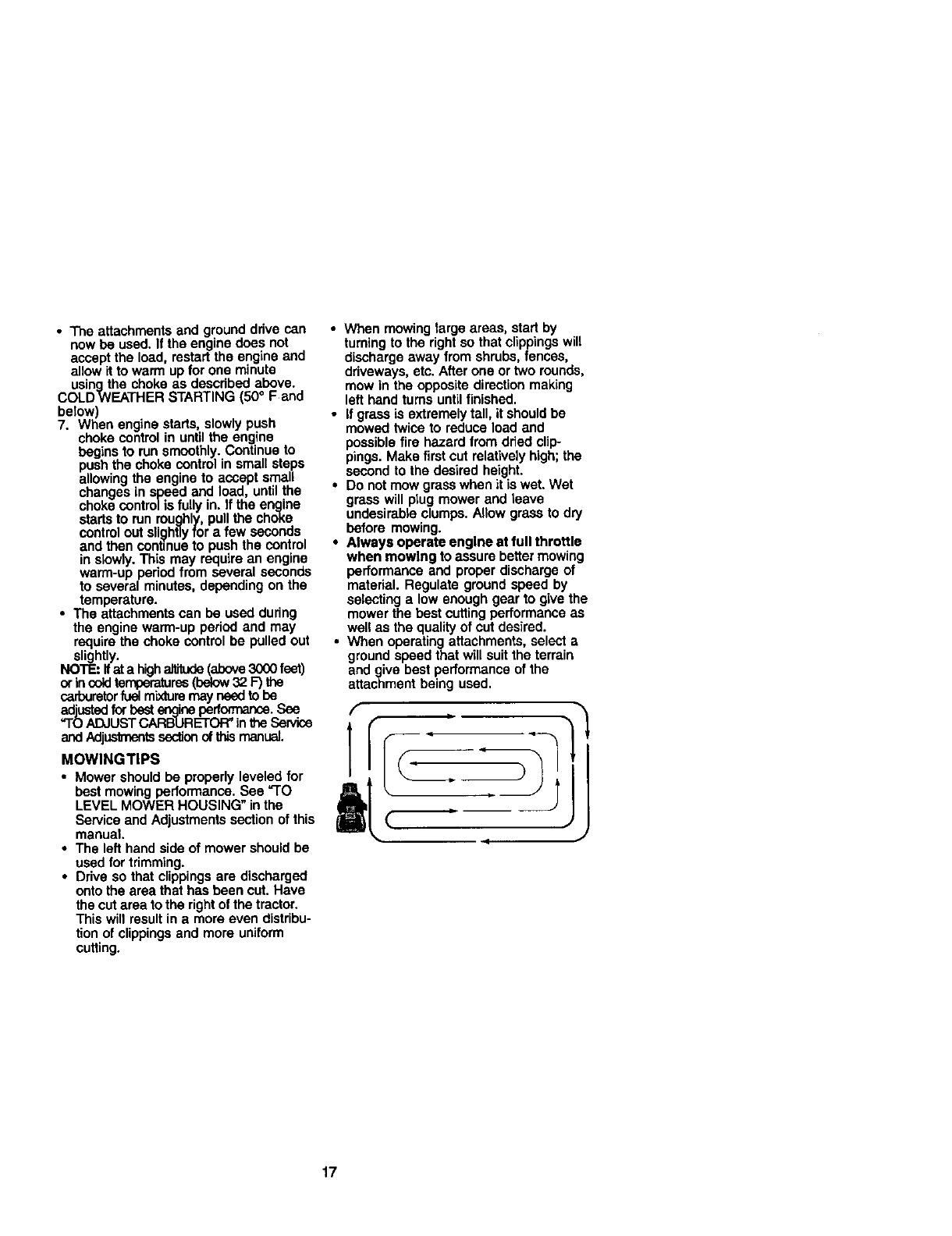
•When mowing large areas, start by
turning to the right so that clippingswill
discharge away from shrubs, fences,
driveways, etc. After one or two rounds,
mow in the opposite direction making
left hand turns until finished.
•If grass is extremely tall, it should be
mowed twice to reduce load and
possible fire hazard from dried clip-
pings. Make first cut relatively high; the
second to the desired height.
•Do not mow grass when it is wet. Wet
grass will plug mower and leave
undesirable clumps. Allow grass to dry
before mowing.
•Always operate engine at full throttle
when mowing to assure better mowing
performance and proper discharge of
material. Regulate ground speed by
selecting a low enough gear to give the
mower the best cutting performance as
well as the qualityof cut desired.
•When operating attachments, select a
ground speed that will suit the terrain
and give best performance of the
attachment being used.
17
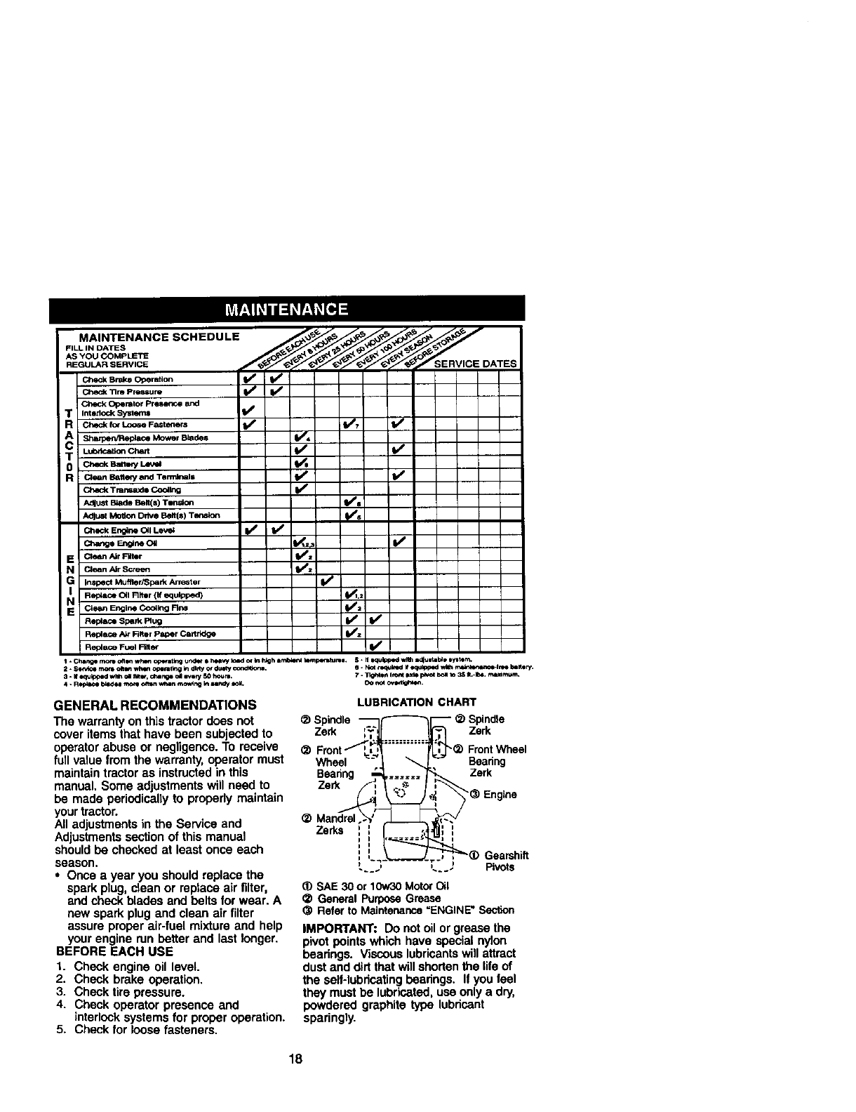
MAINTENANCE SCHEDULE _, _/_/_//_'_/_ _/_e,_/
AS YOU COMPLETE _,_ _
Checkerak=Oper=_on t/ t,/IBIBmm
Check Tlm Pre_ure IV eI_
Check Operator Presm-,ce and
TInterlock _lems I1_
R_for_o_ F_=t_em I,,/ iV" t,/
A_Mower Blades I,_'4
T Lubri_Itlo_Che_ li_ li_
0 Ch*_Bm_ kev_ I_,
RaeanBanew_d Te,',_= t/ V*
C_ckTrar=_*Co_k_O I,/
AdlUSt_BeR(s)T_O_ t/i
AdILU_MoUonDriVeBelt(s) Ten.on _,##_
c_e E_* OU V_u_ V'
E C_ean_r R_r t/=
Nclean Air Screen f/z
G Inspect Muffler/SparK Attester
NI RepCsceOqRl_r (If equipped) _.2
E Cie_In En_Jne_ Coo_lng Rn_ _=
R_pl_ceS_k Ru_ I,/ t,/
Replace A_" triter Paper CartridGe I_=
Re_ece Fuel n.er It/
GENERAL RECOMMENDATIONS
The warranty on this tractor does not
cover items that have been subjected to
operator abuse or negligence. To receive
full value from the warranty, operator must
maintain tractor as instructed in this
manual. Some adjustments will need to
be made periodically to properly maintain
your tractor.
All adjustments in the Service and
Adjustments section of this manual
should be checked at least once each
season.
• Once ayear you should replace the
spark plug, clean or replace air filter,
and check blades and belts for wear. A
new spark plug and clean air filter
assure proper air-fuel mixture and help
your engine run better and last longer.
BEFORE EACH USE
1. Check engine oil level.
2. Check brake operation.
3. Check tire pressure.
4. Check operator presence and
interlock systems for proper operation.
5. Check for loose fasteners.
LUBRICATION CHART
• ) Spindle Spindle
Zerk Zerk
Wh_l
Beadng
Ze_
"(_FmntWheai
Beadng
Ze_
Mandrel
Zerks ',:
i I
_) SAE 30 or 10w30 Moto_ Oil
_) General Purpose Grease
(_ Refer to Maintenance =ENGINE" Section
IMPORTANT: Do not oil or grease the
pivot points which have special nylon
bearings. Viscous lubricants willattract
dust and dirtthat will shorten the life of
the sell-lubdcafing beadngs. If you feel
they must be lubricated, use only a dry,
powdered graphite type lubricant
sparingly.
18
TRACTOR
Always observe safety rules when
performing any maintenance.
BRAKE OPERATION
if tractor requires more than six (6) feet
stoppingdistance at high speed in
highest gear, then brake must be ad-
justed. (See TO ADJUST BRAKE" in the
Service and Adjustments section of this
manual).
TIRES
•Maintain proper air pressure in all tires
(See "PRODUCT SPECIFICATIONS"
section of this manual).
•Keep tires free of gasoline, oil, or insect
control chemicals which can harm
rubber.
•Avoid stumps, stones, deep ruts, sharp
objects and other hazards that may
cause tire damage.
NOTE: To seal tire punctures and prevent
fiat tires due to slow leaks, tire sealant
may be purchased from your local parts
dealer. Tire sealant also prevents tire dry
rot and corrosion.
OPERATOR PRESENCE SYSTEM
Be sure that operator presence and
interlock systems are working properly. If
your tractor does not function as de-
scribed below, repair the problem
immediately.
•The engine should not start unless the
brake pedal is fully depressed and
attachment clutch control is in the
disengaged position.
•When the engine is running, any
attempt by the operator to leave the
seat without flint setting the parking
brake should shut off the engine.
• When the engine is running and the
attachment clutch is engaged, any
attempt by the operator to leave the
seat should shut off the engine.
•The attachment clutch should never
operate unless the operator is in the
seat.
BLADE CARE
For best resultsmower blades must be
kept sharp. Replace bent or damaged
blades.
BLADE REMOVAL
1. Raise mower to highest positionto
allow access to blades.
2. Remove hex bolt, lock washer and flat
washer securing blade.
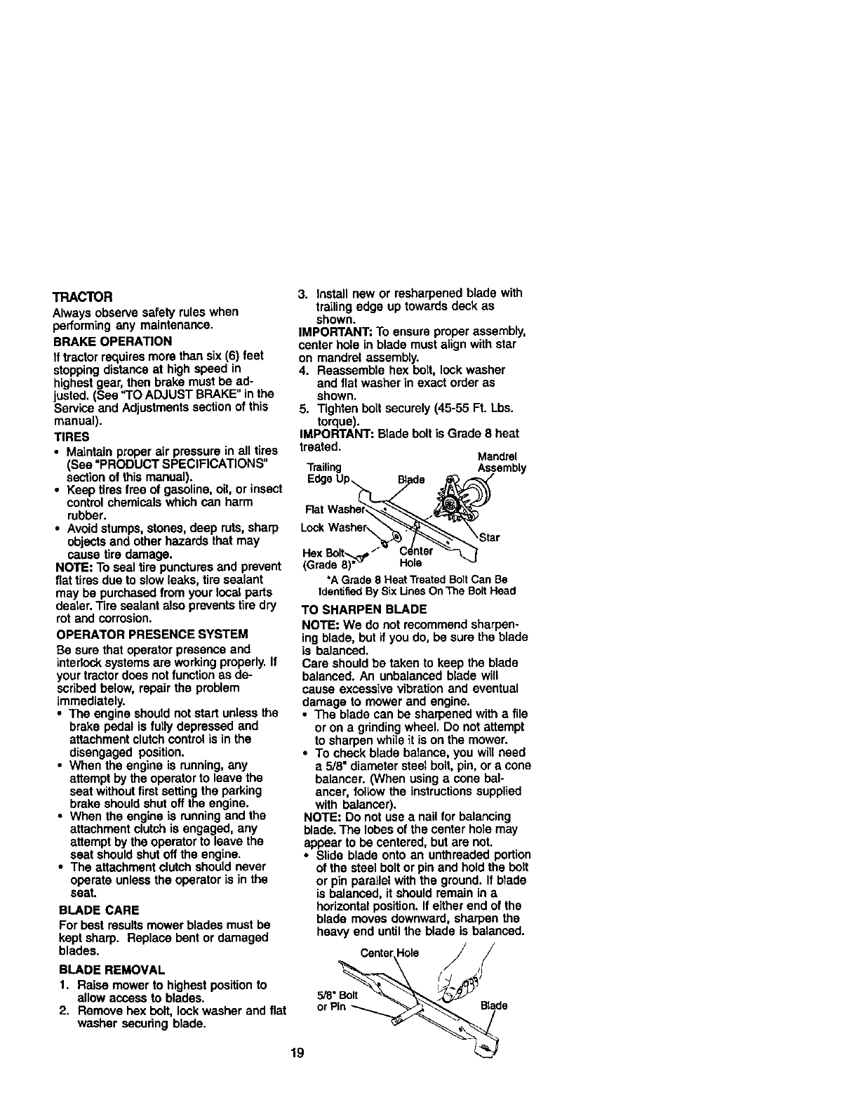
3. Install new or resharpened blade with
trailing edge up towards deck as
shown.
IMPORTANT: To ensure proper assembly,
center hole in blade must align with star
on mandrel assembly.
4. Reassemble hex bolt, lock washer
and flat washer in exact order as
shown.
5. Tighten bolt securely (45-55 Ft. Lbs.
torque).
IMPORTANT: Blade belt is Grade 8 heat
treated. Mandrel
Trailing Assembly
Rat
Lock Washsr_
Hex Bolt,,,.._D
(Grade8)*_ Hole
*A Grade8 HeatTreatedBoltCan Be
IdentifiedBySix LinesOnThe BoltHead
TO SHARPEN BLADE
NOTE: We do not recommend sharpen-
ing blade, but if you do, be sure the blade
is balanced.
Care should be taken to keep the blade
balanced. An unbalanced blade will
cause excessive vibration and eventual
damage to mower and engine.
•The blade can be sharpened with a file
or on a gdnding wheel. Do not attempt
to sharpen while it is on the mower.
•To check blade balance, you will need
a 5/8" diameter steel bolt, pin, or a cone
balancer. (When using a cone bal-
ancer, follow the instructionssupplied
with balancer).
NOTE: Do not use a nail for balancing
blade. The lobes of the center hole may
appear to be centered, but are not.
•Slide blade onto an unthreaded portion
of the steel boltor pin and holdthe bolt
or pin parallel with the ground. If blede
is balanced, it should remain in a
horizontal position. If either end of the
blade moves downward, sharpen the
heavy end until the blade is balanced.
CenterHole J
19 _d
BATrERY
Your tractor has abattery charging system
which is sufficientfor normal use. How-
ever, periodic charging of the battery with
an automotive charger will extend its life.
•Keep battery and terminals clean,
•Keep battery belts tight.
•Keep small vent holes open.
•Recharge at 6-10 amperes for 1 hour.
NOTE: The original equipment battery on
your tractor is maintenance free. Do not
attempt to open or remove caps or covers.
Adding or checking level of electrolyte is
not necessary.
TO CLEAN BA'I-FERYAND TERMINALS
Corrosion and dirt on the battery and
terminals can cause the battery to "leak _
power.
1. Remove terminal guard.
2, Disconnect BLACK battery cable first
then RED battery cable and remove
battery fromtractor,
3, Rinse the battery with plain water and
dry.
4, Clean terminals and battery cable
ends with wire brush until bright.
5, Coat terminals with grease or petro-
leum jelly.
6. Reinstall battery (See "REPLACING
BA'I-I'ERY" in the SERVICE AND
ADJUSTMENTS section of this
manual),
V-BELTS
Check V-belts for deterioration and wear
after 100 hours of operation and replace
if necessary. The belts are not adjustable.
Replace belts it they begin to slip from
wear.
TRANSAXLE COOLING
Keep transaxle free from build-up of dirt
and chaff which can restrictcooling.
ENGINE
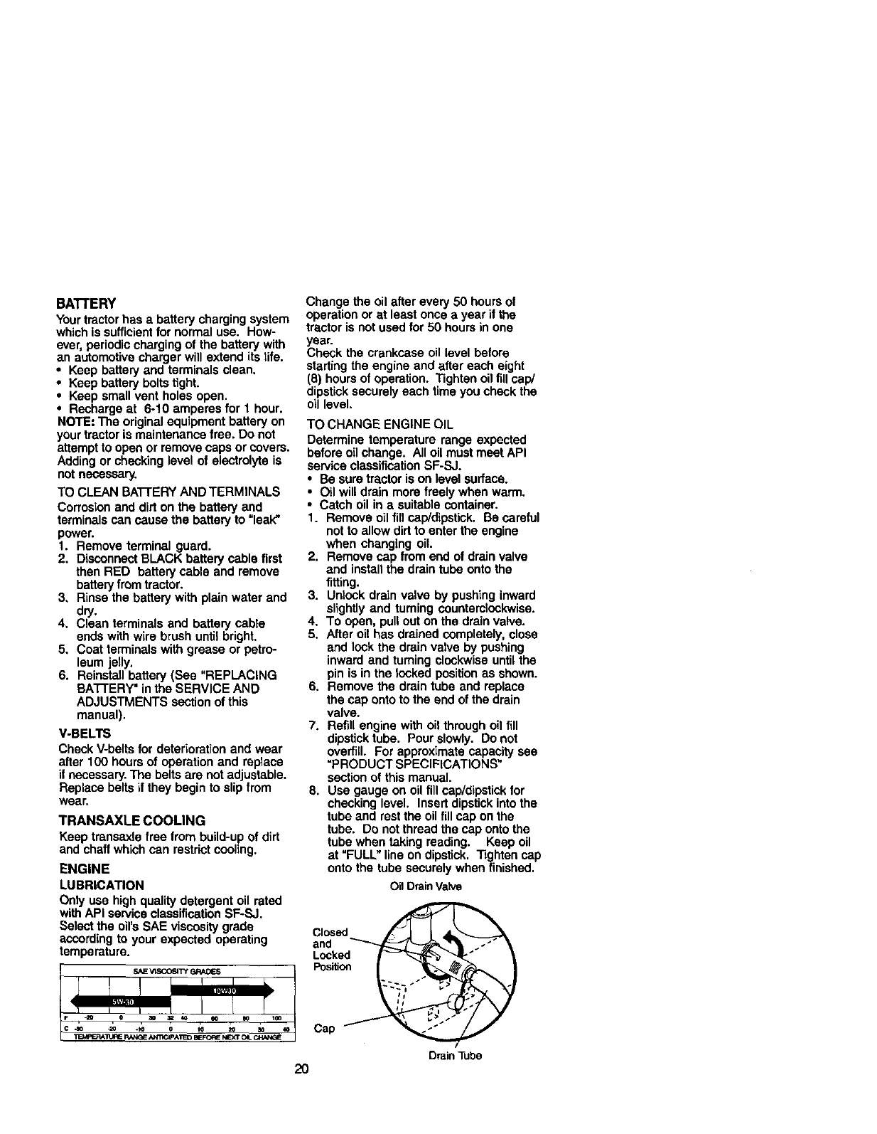
LUBRICATION
Only use high quality detergent oil rated
with API service classification SF-SJ.
Select the oil's SAE viscosity grade
according to your expected operating
temperature.
Change the oil after every 50 hours of
operation or at least once ayear if the
tractor is not used for 50 hours in one
year.
Check the crankcase oil level before
starting the engine and after each eight
(8) hours of operation. Tighten oil fill cap/
dipstick securely each time you check the
oil level.
TO CHANGE ENGINE OIL
Determine temperature range expected
before oil change. All oil must meet API
service classification SF-SJ.
•Be sure tractor is on level surface.
•Oil will drain more freely when warm.
•Catch oil in asuitable cont_ainer.
1. Remove oil fill cap/dipstick. Be careful
not to allow dirt to enter the engine
when changing oil.
2. Remove cap from end of drain valve
and install the drain tube onto the
fitting.
3. Unlock drain valve by pushing inward
slightly and tuming counterclockwise.
4. To open, pull out on the drain valve.
5. After oil has drained completely, close
and lock the drain valve by pushing
inward and turning clockwise untilthe
pin is in the locked position as shown.
6. Remove the drain tube and replace
the cap onto to the end of the drain
valve.
7. Refill engine with oil through oil fill
dipstick tube. Pour slowly. Do not
overfill. For approximate capacity see
=PRODUCT SPECIFICATIONS"
section of this manual.
8. Use gauge on oil fill cap/dipstick for
checking level. Insert dipstick into the
tube and rest the oil fill cap on the
tube. Do not thread the cap onto the
tube when taking reading. Keep oil
at "FULL" line on dipstick. Tighten cap
onto the tube securely when finished.
Oil Drain Valve
Closed
and
Locked
Position
Cap
DrainTube
2O
CLEANAIRSCREEN
Airscreenmustbekept free of dirt and
chaff to prevent engine damage from
overheating. Clean with ewire brush or
compressed air to remove dirt and
stubborn dried gum fibers.
CLEAN AIR INTAKE/COOLING AREAS
To insure proper cooling, make sure the
grass screen, cooling fins, and other
external surfaces of the engine are kept
clean at all times.
Every 100 hours of operation (more often
under extremely dusty, dirty conditions),
remove the blower housing end other
cooling shrouds. Clean the cooling fins
and external surfaces as necessary. Make
sure the cooling shrouds are reinstaned.
NOTE: Operating the engine with a
btecked grass screen, dirty or plugged
cooling fins, and/or cooling shrouds
removed will cause engine damage due
to overheating.
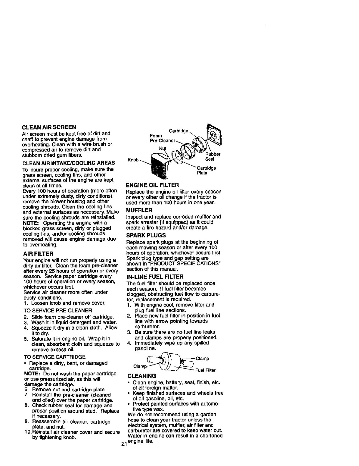
AIR FILTER
Your engine will not run properly using a
dirty airfilter. Clean the foam pre-cleaner
after every 25 hours of operation or every
season. Service paper cartridge every
100 hours of operation or every season,
whichever occurs first.
Service air cleaner more often under
dusty conditions.
1. Loosen knob and remove cover.
TO SERVICE PRE-CLEANER
2. Slide foam pre-cleaner off cartridge.
3. Wash it in liquid detergent and water.
4. Squeeze it dry in a clean cloth. Allow
itto dry.
5. Saturate it in engine oil. Wrap it in
clean, absorbent cloth and squeeze to
remove excess oil.
TO SERVICE CARTRIDGE
•Replace adirty, bent, or damaged
cartridge.
NOTE: Do not wash the paper cartridge
or use pressurized air, as this will
damage the cartridge.
6. Remove nut and cartridge plate.
7. Reinstall the pre-cleaner (cleaned
and oiled) over the paper cartridge.
8. Check rubber seal for damage and
proper position around stud. Replace
if necessary.
9. Reassemble air cleaner, cartridge
plate, and nut.
10.Reinstall air cleaner cover and secure
by tightening knob.
Foam
Knob_
Rubber
Se_
Cadddge
Plate
ENGINE OIL FILTER
Replace the engine oil filter every season
or every other oil change ifthe tractor is
used more than 100 hours in one year.
MUFFLER
Inspect and replace corroded muffler and
spark arrester (if equipped) as it could
create a fire hazard and/or damage.
SPARK PLUGS
Replace spark plugs at the beginning of
each mowing season or after every 100
hours of operation, whichever occurs first.
Spark plug type end gap setting are
shown in =PRODUCT SPECIFICATIONS"
section of this manual
IN-LINE FUEL FILTER
The fuel filter should be replaced once
each seeson. If fuel filter becomes
clogged, obstructingfuel flow to carbure-
tor, replacement is required.
1. With engine cool, remove filter and
plug fuel line sections.
2. Piece new fuel filter in position in fuel
line with arrow pointing towards
carburetor.
3. Be sure there are no fuel line leaks
and clamps are properly positioned.
4. Immediately wipe up any spilled
gasoline.
Clamp
Clamp--"f _ FuelNiter
CLEANING
•Clean engine, battery, seat, finish, etc.
of ell foreign matter.
•Keep finished surfaces and wheels free
of all gasoline, oil, etc.
•Protect painted surfaces with automo-
tive type wax.
We do not recommend using a garden
hose to clean your tractor unless the
electrical system, muffler,air filter and
carburetor are covered to keep water out.
Water in engine can resultin ashortened
21 engine life.
_CAUTION: BEFORE PERFORMING ANY SERVICE OR ADJUSTMENTS:
1. Depress clutch/brake pedal fully and set parking brake.
2. Place gearshift lever in neutral (N) position.
3. Place attachment clutch in =DISENGAGED" position.
4. Turn ignition key "OFF" and remove key.
5. Make sure the blades and all moving parts have completely stopped.
6. Disconnect spark plug wire from spark plug and place wire where it cannot
come in contactwith plug.
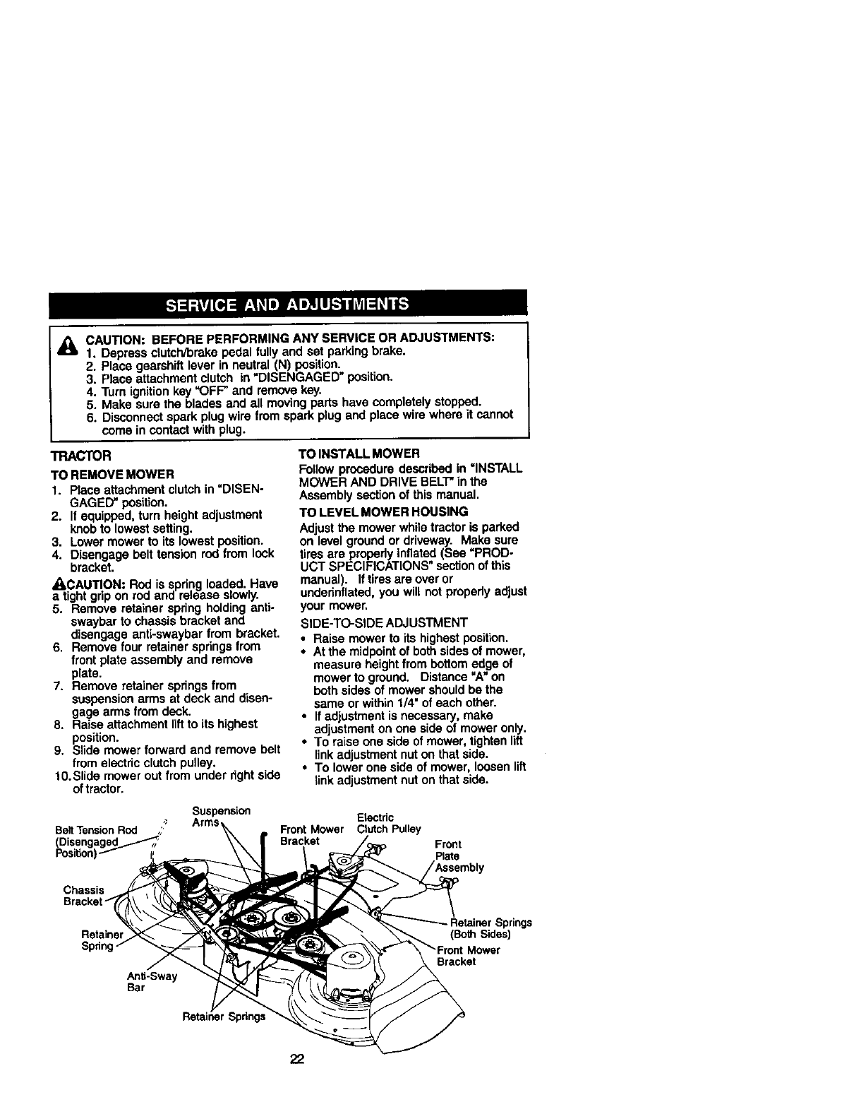
TRACTOR
TO REMOVE MOWER
1. Place attachment clutch in uDISEN-
GAGED" posit_on.
2. If equipped, turn height adjustment
knob to lowest setting.
3. Lower mower to its lowest position.
4. Disengage bolt tension red from look
bracket.
•kCAUTION: Rod is spring loaded. Have
a tight grip on red and release slowly.
5. Remove retainer spdng holding anti-
swaybar to chassis bracket and
disengage anti-swaybar from bracket.
6. Remove four retainer springs from
front plate assembly and remove
plate.
7. Remove retainer springs from
suspension arms at deck and disen-
gage arms from deck.
8. Raise attachment lift to its highest
position.
9. Slide mower forward and remove bolt
from electdc clutch pulley.
10.Slide mower out from under nght side
of tractor.
TO INSTALL MOWER
Follow procedure described in =INSTALL
MOWER AND DRIVE BELT in the
Assembly section of this manual.
TO LEVEL MOWER HOUSING
Adjust the mower while tractor is parked
on level ground or driveway. Make sure
tires are properly inflated (See =PROD-
UCT SPECIFICATIONS" sectionof this
manual). If tires are over or
undednflated, you will not properly adjust
your mower.
SIDE-TO-SIDE ADJUSTMENT
•Raise mower to its highest position.
•At the midpointof both sides of mower,
measure height from bottom edge of
mower to ground. Distance "A" on
both sides of mower should be the
same or within 1/4" of each other.
•If adjustment is necessary, make
adjustment on one side of mower only.
•To raise one side of mower, tighten lift
linkadjustment nut on that side.
•To lower one side of mower, loosen lift
link adjustment nut on that side.
Belt Tension Rod ,,?
(Disengagad_....----'_i
Position)
Suspension
Arms Etectdc
Front Mower Clutch Pulley
Bracket Front
Plate
Chassis
Retainer
Anti-Sway
Bar
Spnngs
;prings
(Both Sides)
Mower
Bracket
22
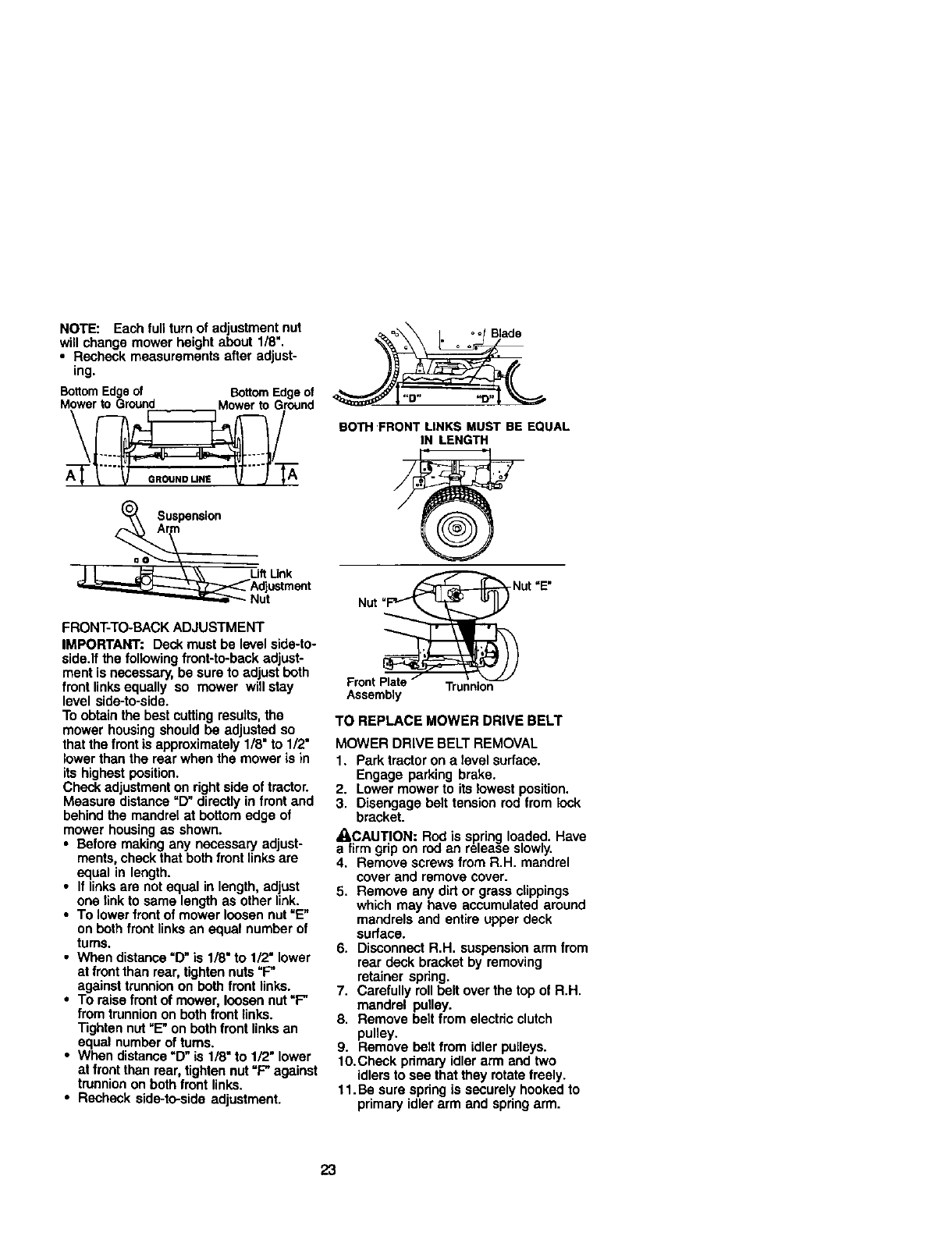
NOTE: Each full turn of adjustment nut
will change mower height about 1/8".
•Recheck measurements after adjust-
ing.
BottomEdgeof BottomEdgeof
Mowerto Ground Mowerto Ground
\/
=A__ Suspensi°n
J L _\\ Lift Unk
_Adjustment _""--- Nut
FRONT-TO-BACK ADJUSTMENT
IMPORTANT: Deck must be level side-to-
side.If the following front-to-back adjust-
ment is necessary, be sure to adjust both
front linksequally so mower will stay
level side-to-side.
To obtain the best cutting results, the
mower housing should be adjusted so
that the front is approximately 1/8" to 1/2"
lower than the rear when the mower is in
its highest position.
Check adjustment on right side of tractor.
Measure distance "D" directly in front and
behind the mandrel at bottom edge of
mower housing as shown.
• Before making any necessary adjust-
ments, check that both front links are
equal in length.
•If linksare not equal in length, adjust
one link to same length as other link.
•To lower front of mower loosen nut "E"
on both front links an equal number of
tums.
•When distance =D"is 1/8" to 1/2" lower
at frontthan rear, tighten nuts "F"
against trunnion on both front links.
•To raise front of mower, loosen nut "F"
from trunnion on both front links.
Tighten nut "E" on both front links an
equal number of turns.
•When distance "13"is 1/8" to 1/2" lower
at front than rear, tighten nut =F" against
trunnion on both front links.
•Recheck side-to-side adjustment.
=_ oo Blade
a = o =
BOTH "FRONTLINKS MUST BE EQUAL
IN LENGTH
-Nut "E"
Nut
Front Plate Trunnion
Assembly
TO REPLACE MOWER DRIVE BELT
MOWER DRIVE BELT REMOVAL
1. Park tractor on a level surface.
Engage parking brake.
2. Lower mower to its lowest position.
3. Disengage belt tension rod from lock
bracket.
A, CAUTION: Rod is spring loaded. Have
a firm grip on rod an release slowly.
4. Remove screws from R.H. mandrel
cover and remove cover.
5. Remove any dirt or grass clippings
which may have accumulated around
mandrels and entire upper deck
surface,
6. Disconnect R.H. suspension arm from
rear deck bracket by removing
retainer spring.
7. Carefully roll bolt over the top of R.H.
mandrel pulley.
8. Remove bait from electric clutch
puney.
9. Remove belt from idler pulleys.
10.Check primary idler arm and two
idlers to see that they rotate freely.
11.Be sure spring is securely hooked to
primary idler arm and spring arm.
23
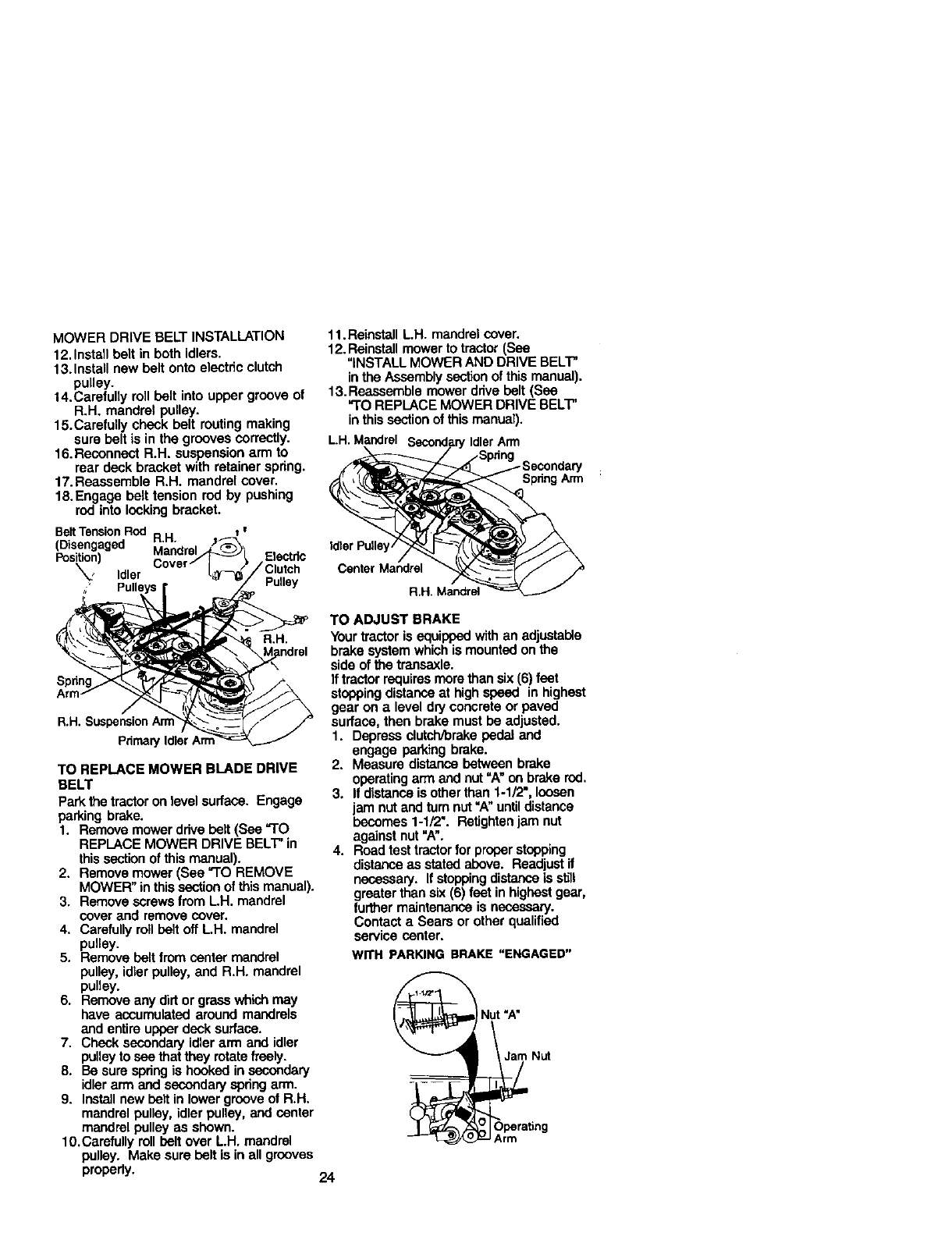
MOWER DRIVE BELT INSTALLATION
12. Install belt in both idlers.
13.Install new belt onto electric clutch
pulley.
14.Carefully roll belt into upper groove of
R.H. mandrel pulley.
15.Carefully check belt routing making
sure belt is in the grooves correctly.
16.Reconnoct R.H. suspension arm to
rear deck bracket with retainer spdng.
17. Reassemble R.H. mandrel cover.
18.Engage belt tension rod by pushing
rod into locking bracket.
Bait Tension Rod R.H. t w
(Disengaged Mandrel
Position) Electdc
_, Idler /Clutch
•Pulley
R•H,
a•H,
Prir'nar_
TO REPLACE MOWER BLADE DRIVE
BELT
Park the tractor on level surface. Engage
parking brake.
1. Remove mower ddve belt (See "TO
REPLACE MOWER DRIVE BELT" in
this sectionof this manual).
2. Remove mower (See "TO REMOVE
MOWER" in this sectionof this manual).
3. Remove screws from L.H. mandrel
cover and remove cover.
4. Carefully roll belt off L.H. mandrel
pulley.
5. Remove belt from center mandrel
pulley, idler pulley, and R.H. mandrel
pulley.
6. Remove any dirt or grass which may
have accumulated around mandrels
and entire upper deck surface•
7. Check secondary idler arm and idler
pulley to see that they rotatefreely.
8. Be sure spring is hooked in secondary
idler arm and secondary spring arm.
9. Install new belt in lower groove ol R.H.
mandrel pulley, idler pulley, and center
mandrel pulley as shown.
10.Carefully roll belt over L.H. mandrel
pulley. Make sure belt is in all grooves
propedy.
11.Reinstall L.H. mandrel cover.
12. Reinstall mower to tractor (See
"INSTALL MOWER AND DRIVE BELT"
in the Assembly section of this manual).
13. Reassemble mower drive belt (See
"TO REPLACE MOWER DRIVE BELT"
in this section of this manual).
LH. Mandrel Secondary Idler Arm
Spring Arm
Idler Pulls
Center Mandrel
R.H. Mandrel
TO ADJUST BRAKE
Your tractor is equipped with an adjustable
brake system which is mounted on the
side of the transaxle.
Iftractor requires more than six (6) feet
stoppingdistance at high speed in highest
gear on alevel dry concrete or paved
surface, then brake must be adjusted.
1. Depress clutch/brakepeda_and
engage parking brake.
2. Measure distance between brake
operating arm and nut "A"on brake rod.
3. If distance is other than 1-1/2", loosen
jam nut and turn nut "A" untildistance
becomes 1-1/2". Retightenjam nut
against nut "A".
4. Road test tractorfor properstopping
distance as stated above. Readjust if
necessary. If stoppingdistance is still
greater than six (6) feet in highest gear,
further maintenance is necessary.
Contact a Sears or other qualified
service center.
WITH PARKING BRAKE "ENGAGED"
Nut"A"
Jam Nut
_ _ _n¥-ting
24
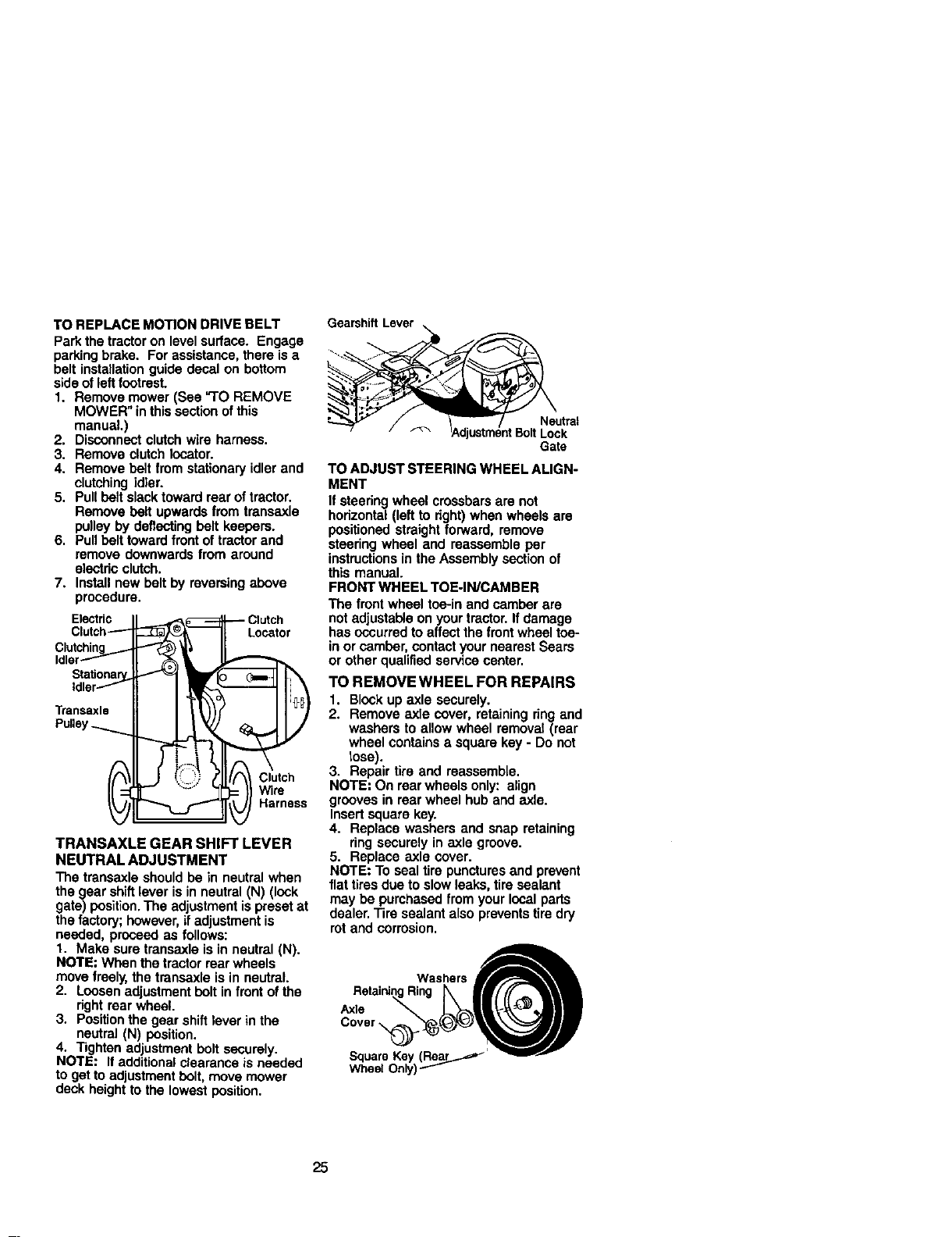
TO REPLACE MOTION DRIVE BELT
Park the tractor on level surface. Engage
parking brake. For assistance, there is a
belt installation guide decal on bottom
side of leftfootrest.
1. Remove mower (See "TO REMOVE
MOWER" in thissection of this
manual.)
2. Disconnect clutch wire hamass.
3. Remove clutch Iocator.
4. Remove belt from stationary idler and
clutching idler.
5. Pull belt slack toward rear of tractor.
Remove belt upwards from trensaxle
pulley by deflecting belt keepers.
6. Pull belt toward front of tractor and
remove downwards from around
electdc clutch.
7. Install new belt by reversing above
procedure.
Electric
Clutch_
Clutching_..-
Idler--""-
Stationa_.
tdler---"f
Transaxle
Pulley
Clutch
W1
TRANSAXLE GEAR SHIFT LEVER
NEUTRAL ADJUSTMENT
The transaxle should be in neutral when
the gear shiftlever is in neutral (N) (look
gate) position.The adjustment is preset at
the factory; however, if adjustment is
needed, proceed as follows:
1. Make sure transaxle is in neutral (N).
NOTE: When the tractor rear wheels
move freely, the transaxle is in neutral.
2. Loosen adjustment bolt in front of the
right rear wheel.
3. Position the gear shift lever in the
neutral (N) position.
4. Tighten adjustment bolt securely.
NOTE: If additional clearance is needed
to get to adjustment bolt, move mower
deck height to the lowest position.
Gearshift Lever
Neutral
BoR Lock
G_e
TO ADJUST STEERING WHEEL ALIGN-
MENT
If steering wheel crossbars are not
horizontal (left to dght)when wheels are
positioned straight forward, remove
steering wheel and reassemble per
instructionsin the Assembly section of
this manual.
FRONT WHEEL TOE-IN/CAMBER
The front wheel toe-in and camber are
not adjustable on your tractor. If damage
has occurred to affect the front wheel toe-
in or camber, contact your nearest Sears
or other qualified service center.
TO REMOVE WHEEL FOR REPAIRS
1. Block up axle securely.
2. Remove axle cover, retaining ring and
washers to allow wheel removal (rear
wheel contains asquare key - Do not
lose).
3. Repair tire and reassemble.
NOTE: On rear wheels only: align
grooves in rear wheel hub and axle.
Insert square key.
4. Replace washers and snap retaining
ring securely in axle groove.
5. Replace axle cover.
NOTE: To seal tire punctures and prevent
flat tires due to slow leaks, tire sealant
may be purchased from your local parts
dealer. Tire sealant also prevents tire dry
rot and corrosion.
ReOi,oQ
25
TO STARTENGINEWITI'I AWEAK
BA'rTERY
_,CAUTION: Leed-acid batteries
generate explosive gases. Keep sparks,
flame and smoking materials away from
batteries. Always wear eye protection
when around batteries.
If your battery is too weak to start the
engine, it should be recharged. (See
"BA'I3"ERY" in the MAINTENANCE
section of this manual).
If "jumpercables" are used for emergency
starting, follow this procedure:
IMPORTANT: Your tractor is equipped
with a12 volt negative grounded system.
The other vehisel must also be a 12 volt
negative grounded system. Do not use
your tractor battery to start other vehicles.
TO ATTACHJUMPER CABLES -
1. Connect each end of the RED cable to
the POSITIVE (+) terminal of each
battery, taking care not to short
against chassis.
2. Connect one end of the BLACK cable
to the NEGATIVE (-) terminal of fully
charged battery.
3. Connect the other end of the BLACK
cable to good CHASSIS GROUND,
away from fuel tank and battery.
TO REMOVE CABLES, REVERSE
ORDER -
1. BLACK cable first from chassis and
then from the fully charged battery.
2. RED cable last from both batteries.
=Positive"(+) =Negative"(-)
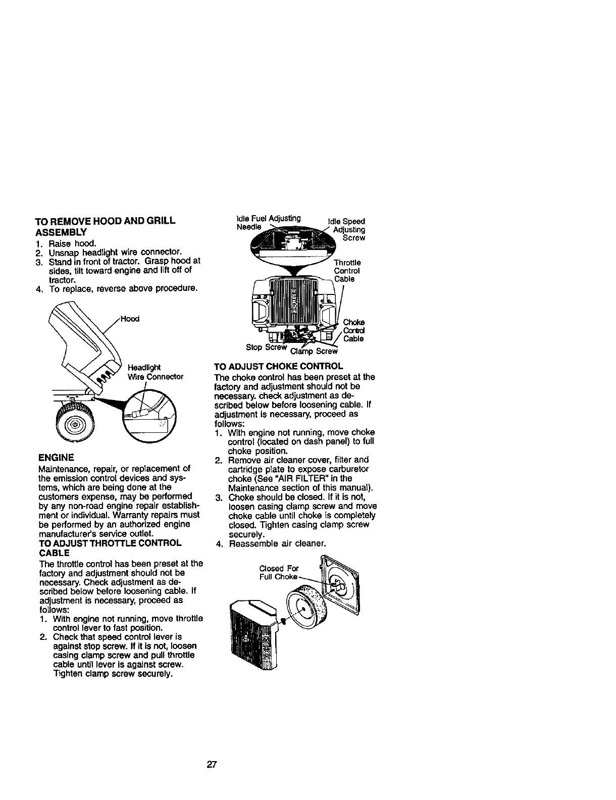
REPLACING BATrERY
ACAU.TION: Do not short batter/
terminals by allowing a wrench or any
other object to contact both terminals at
the same time. Before connecting battery,
remove metal bracelets, wristwatch
bands, dogs, etc.
Positive terminal must be connected first
to prevent sparking from accidental
grounding.
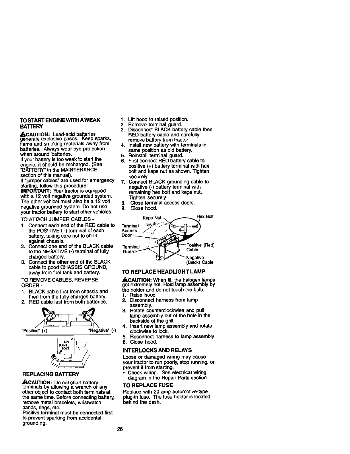
1. Lift hoed to raised position.
2. Remove terminal guard.
3. Disconnect BLACK battery cable then
RED battery cable and carefully
remove battery from tractor.
4. Install new battery with terminals in
same position as old battery.
5. Reinstall terminal guard.
6. First connect RED battery cable to
positive (+) battery terminal with hex
bolt and keps nut as shown. Tighten
securely.
7. Connect BLACK grounding cable to
negative (-) battery terminal with
remaining hex bolt and kepe nut.
Tighten securely
8. Close terminal access doors.
9. Close hood.
Keps Nut _f._ ex B°lt
Terminal "_,i_"%::_:_ --_ ,_
Access ..::_" j" _-:
Door _
Terminal _ .[_--Positive (Red)
Guar_.j_ I _Cable
_'_ _" Negative
(Black) Cable
TO REPLACE HEADLIGHT LAMP
_I,CAUTION: When lit the halogen lamps
get extremely hot. Hold lamp assembly ey
the holder and do not touch the bulb.
1. Raise hood.
2. Disconnect harness from lamp
assembly.
3. Rotate counterclockwise and pull
lamp assembly out of the hole in the
backside of the grill.
4. Insert new lamp assembly and rotate
clockwise to lock.
5. Reconnect harness to lamp assembly.
6. Close hood.
INTERLOCKS AND RELAYS
Loose or damaged wiring may cause
your tractorto run poorly, stop running, or
prevent it from starting.
•Check wiring. See electrical wiring
diagram in the Repair Parts section.
TO REPLACE FUSE
Replace with 20 amp automotive-type
plug-in fuse. The fuse holder islocated
behind the dash.
26
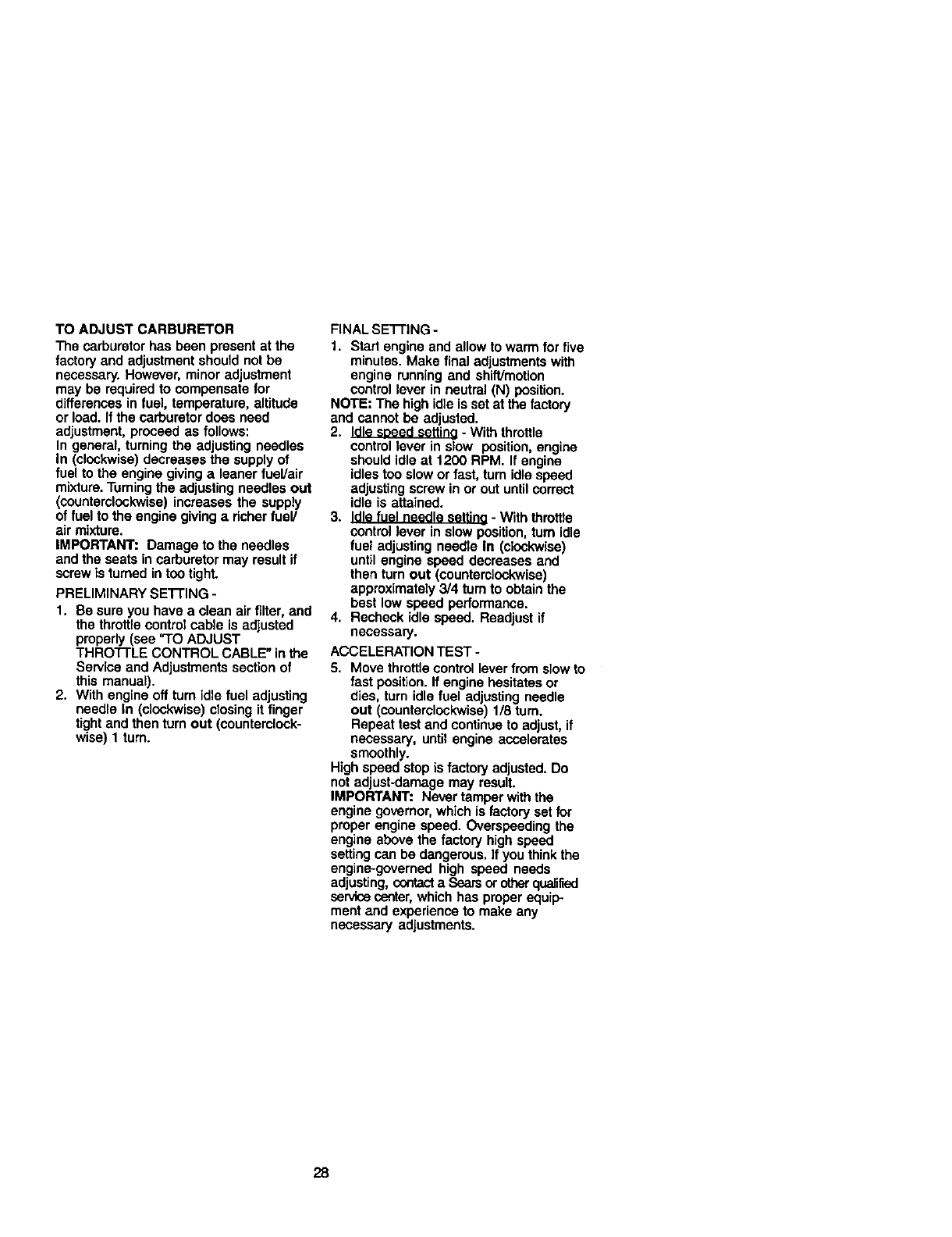
TO REMOVE HOOD AND GRILL
ASSEMBLY
1. Raise hood.
2. Unsnap headlight wire connector.
3. Stand in front of tractor. Grasp hood at
sides, tilttoward engine and liftoff of
tractor.
4. To replace,
J
<
®
reverse above procedure.
Hood
,)
ENGINE
Maintenance, repair, or replacement of
the emission control devices and sys-
tems, which are being done at the
customers expense, may be performed
by any non-road engine repair establish-
ment or individual. Warranty repairs must
be performed by an authorized engine
manufacturer's service outlet.
TO ADJUST THROTTLE CONTROL
CABLE
The throttle controlhas been preset at the
factory and adjustment should not be
necessary. Check adjustment as de-
scribed below before loosening cable. If
adjustment is necessary, proceed as
follows:
1. With engine not running, move throttle
control lever to fast position.
2. Check that speed control lever is
against stop screw. If it is not, loosen
casing clamp screw and pull throttle
cable until lever is against screw.
Tighten clamp screw securely.
Idle Fuel Adjusting Idle Speed
Needle
Screw
Control
Cable
_hoke
Cord
/Cable
Stop ) Screw
TO ADJUST CHOKE CONTROL
The choke control has been preset at the
factory and adjustment should not be
necessary, check adjustment as de-
scribed below before loosening cable. If
adjustment is necessary, proceed as
follows:
1. With engine not running, move choke
control (located on dash panel) to full
choke position.
2. Remove air cleaner cover, filter and
cartridge plate to expose carburetor
choke (See =AIR FILTER" in the
Maintenance section of this manual).
3. Choke should be closed. If it is not,
loosen casing clamp screw and move
choke cable until choke is completely
closed. Tighten casing clamp screw
securely.
4. Reassemble air cleaner.
Closed For
27
TO ADJUST CARBURETOR
The carburetor has been present at the
factory and adjustment should not be
necessary. However, minor adjustment
may be required to compensate for
differences in fuel, temperature, altitude
or load. If the carburetor does need
adjustment, proceed as follows:
In general, turning the adjusting needles
In (clockwise) decreases the supply of
fuel to the engine giving a leaner fuel/air
mixture.Turning the adjusting needles out
(countemlockwise) increases the supply
of fuel to the engine giving a richer fuel/
air mixture.
IMPORTANT: Damage to the needles
and the seats in carburetor may result if
screw is turned in too tight.
PRELIMINARY SE'I-rlNG -
1. Be sure you have a clean air filter, and
the throttle control cable is adjusted
properly (see "TO ADJUST
THRO'I-I'LE CONTROL CABLE" in the
Service and Adjustments section of
this manual).
2. With engine off turn idle fuel adjusting
needle In (clockwise) closing it finger
tight and then turn out (counterclock-
wise) 1turn.
FINAL SE'I-I'ING -
1. Start engine and allow to warm for five
minutes. Make final adjustments with
engine running and shift]motion
control lever in neutral (N) position.
NOTE: The high idle is sat at the factory
and cannot be adjusted.
2. Idle seeed settino - With throttle
control lever in slow position, engine
should idle at 1200 RPM. If engine
idles too slow or fast, turn idle speed
adjusting screw in or out until correct
idle is attained.
3. Idle fuel needle setting -With throttle
oontrol lever in slow position, turn idle
fuel adjusting needle in (clockwise)
until engine speed decreases and
then turn out (countemlookwise)
approximately 3/4 turn to obtain the
best low speed performance.
4. Recheck idle speed. Readjust if
necessary.
ACCELERATION TEST -
5. Move throttle control lever from slow to
fast position. If engine hesitates or
dies, turn idle fuel adjusting needle
out (counterclockwise) 1/8 turn.
Repeat test and continue to adjust, if
necessary, until engine accelerates
smoothly.
High speed stop is factory adjusted. Do
not adjust-damage may result.
IMPORTANT: Ne_._rtamper with the
engine governor, which is factory set for
proper engine speed. Overspeeding the
engine above the factory high speed
setting can be dangerous. Ifyou think the
engine-governed high speed needs
adjusting, contact a Sears or other quaJilied
servicecenter, which has proper equip.
ment and experience to make any
necessary adjustments.
28
Immediately prepare your tractor for
storage at the end ofthe season or ilthe
tractor will not be used for 30 days or
more.
_CAUTION: Never store the tractor with
gasoline in the tank inside abuilding
where fumes may reach an open flame or
spark. Allow the engine to cool before
storing in any enclosure.
TRACTOR
Remove mower from tractor for winter
storage. When mower is to be stored for
aperiod of time, clean itthoroughly,
remove all dirt, grease, leaves, etc. Store
in a clean, dry area.
1. Clean entire tractor (See "CLEANING"
in the Maintenance section of this
manual).
2. Inspect and replace belts, if necessary
(See belt replacement instructionsin
the Service and Adjustments section
of this manual).
3. Lubricate as shown in the Mainte-
nance section of this manual.
4. Be sure that all nuts, bolts and screws
are securely fastened. Inspect moving
parts for damage, breakage and wear.
Replace if necessary.
5. Touch up all rusted or chipped paint
surfaces; sand lightly before painting.
BATTERY
• Fully charge the battery for storage.
• After a period of time in storage, battery
may require recharging.
•To help prevent corrosion and power
leakage during long periods of storage,
battery cables should be disconnected
and battery cleaned thoroughly (see
"TO CLEAN BA'I-I'ERY AND TERMI-
NALS" in the Maintenance section of
this manual).
•Alter cleaning, leave cables discon-
nected and place cables where they
cannot come in contact with battery
terminals.
•If battery is removed from tractor for
storage, do not store battery directly on
concrete or damp surfaces.
ENGINE
FUEL SYSTEM
IMPORTANT: Itis important to prevent
gum depesites from forming in essential
fuel system parts such as carburetor, fuel
hose, or tank duringstorage.
Also, experience indicates that alcohol
blended fuels (called gasohol or using
ethanol or methanol) can attract moisture
which leads to separation and formation
of acids during storage. Acidic gas can
damage the fuel system of and engine
while in storage,
1. Drain the fuel tank.
2. Start the engine and let it run until the
fuel lines and carburetor are empty.
• Never use engine or carburetor cleaner
products in the fuel tank or permanent
damage may occur.
• Use fresh fuel next season.
NOTE= Fuel stabilizer is an acceptable
alternative in minimizing the formation of
fuel gum deposits during storage. Add
stabilizer to gasoline in fuel tank or
storage container. Always follow the mix
ratio found on stabilizer container. Run
engine at least 10 minutes after adding
stabilizer to allow the stabilizer to reach
the carburetor. Do not drain the gas tank
and carburetor if using fuel stabilizer.
ENGINE OIL
Drain oil (with engine warm) end replace
with clean engine oil. (See "ENGINE" in
the Maintenance section of this manual).
CYLINDER(S)
1. Remove spark plug(s).
2. Pour one ounce of oil through spark
plug hole(s) into cylinder(s).
3. Turn ignitionkey to =START" position
for a few seconds to distribute oil.
4. Replace with new spark plug(s).
OTHER
•Do not store gasoline from one season
to another.
•Replace your gasoline can if your can
starts to rust. Rust and/or dirt inyour
gasoline will cause problems.
•If possible, store your tractor indoors
and cover itto give protectionfrom dust
and did.
•Cover your tractor with a suitable
protective cover that does not retain
moisture. Do not use plastic. Plastic
cannot breathe which allows conden-
cation to form and will cause your
tractor to rust.
IMPORTANT: Never cover tractor while
engine and exhaust areas are still warm.
29
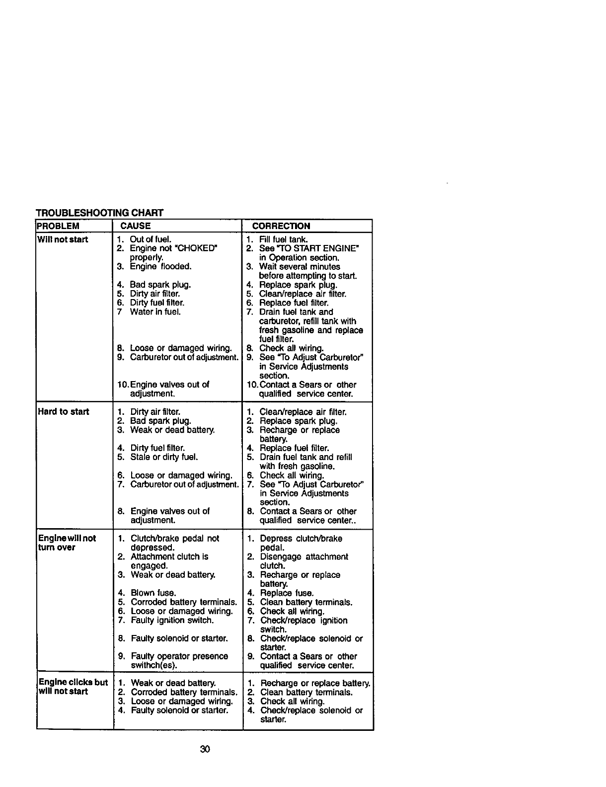
TROUBLESHOOTING CHART
PROBLEM CAUSE
WIll not start 1. Out of fuel.
Hard to start
Enginewlll not
turn over
2. Engine not "CHOKED"
properly.
3. Engine flooded.
4. Bad spark plug.
5. Dirty air filter.
6. Dirty fuel filter.
7 Water in fuel.
8. Loose or damaged wiring.
9. Carburetor out of adjustment.
10. Engine valves out of
adjustment.
1. Dirty air filter.
2. Bad spark plug.
3. Weak or dead battery.
4. Dirty fuel filter.
5. Stale or dirty fuel.
6. Loose or damaged wiring.
7. Carburetor out of adjustment.
8. Engine valves out of
adjustment.
1. Clutch/brake pedal not
depressed.
2. Attachment clutch is
engaged.
3. Weak or dead battery.
4. Blown fuse.
5. Corroded battery terminals.
6. Loose or damaged wiring.
7. Faulty ignition switch,
8. Faulty solenoid or starter.
9, Faulty operator presence
swithch(es).
t, Weak or dead battery.
2. Corroded battery terminals.
3. Loose or damaged widng.
4. Faulty solenoid or starter.
Engine clicks but
NIII not start
CORRECTION
1. Fill fuel tank.
2. See "TO START ENGINE"
in Operation section.
3. Wait several minutes
before attemptingto start.
4. Replace spark plug.
5. Clean/replace air filter.
6. Replace fuel filter.
7. Drain fuel tank and
carburetor, refilltank with
fresh gasoline and replace
fuel filter.
8. Check all widng.
9. See "To Adjust Carburetor"
in Service Adjustments
section.
10.Contact a Sears or other
qualified service center.
1. Clean/replace air filter.
2. Replace spark plug.
3. Recharge or replace
battery.
4. Replace fuel filter.
5. Drain fuel tank and refill
with fresh gasoline.
6. Check all widng.
7. See "To Adjust Carburetor"
in Service Adjustments
section.
8. Contact a Sears or other
qualified service center..
1. Depress clutch/brake
pedal.
2. Disengage attachment
clutch.
; 3. Recharge or replace
battery.
4. Replace fuse.
5. Clean battery terminals.
6. Check all widng.
7. Checldmplace ignition
switch.
8. Check/replace solenoid or
starter.
9. Contact a Sears or other
qualified service center.
1. Recharge or replace battery
2. Clean battery terminals.
3. Check all widng.
4. Check/replace solenoid or
starter.
30
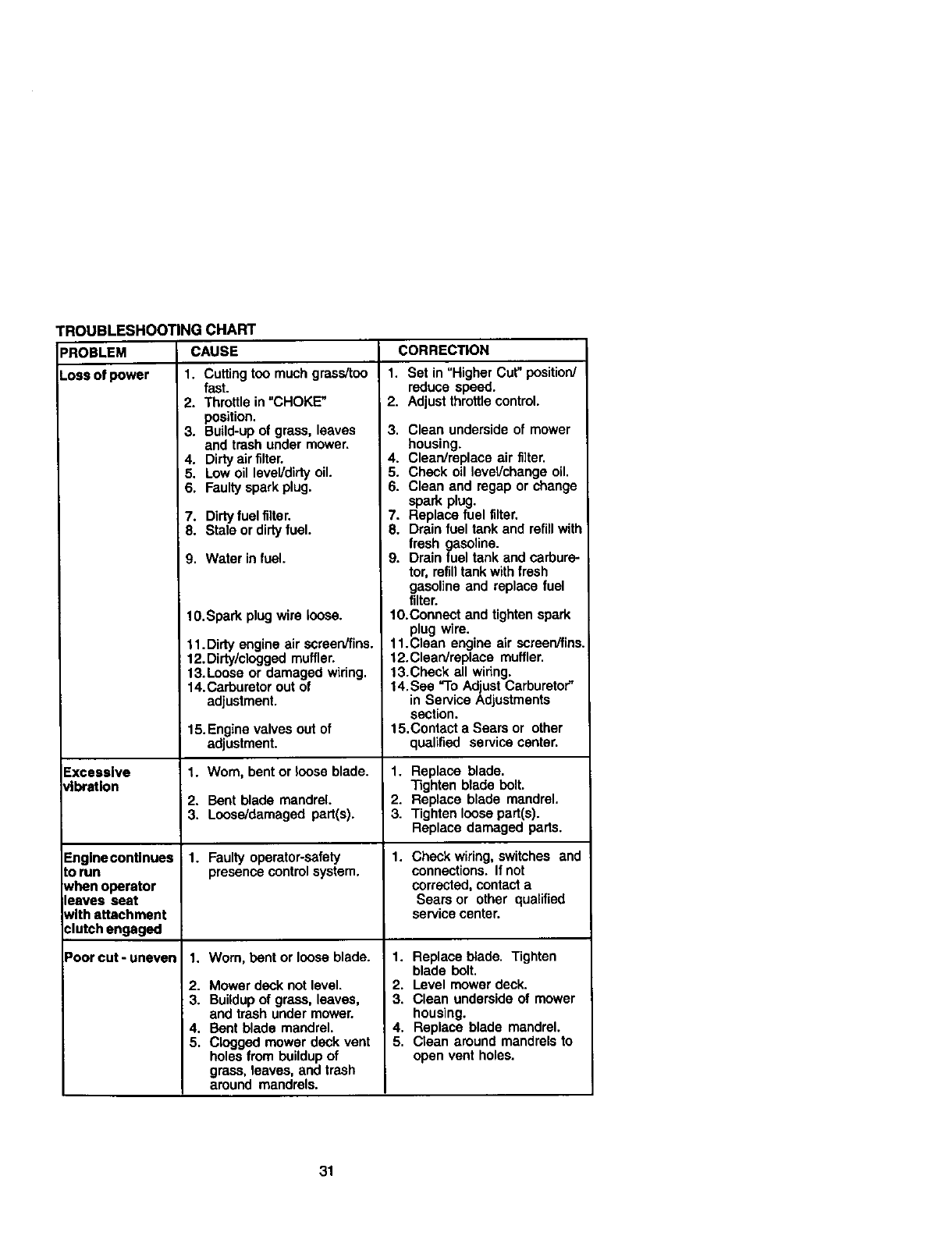
TROUBLESHOOTING CHART
PROBLEM CAUSE CORRECTION
Loss_power 1. Cuffingtoo muchgras_oo
Excessive
_bratlon
Englnecontlnues
to run
when operator
leaves seat
with attachment
clutch engaged
Poorcut-uneven
fast.
2. Throttle in =CHOKE"
position.
3. Build-up of grass, leaves
and trash under mower.
4. Dirty air filter.
5. Low oil level/dirty oil.
6. Faulty spark plug.
7. Dirtyfuel filter.
8. Stale or dirtyfuel.
9. Water in fuel.
10.Spark plug wire loose.
11. Dirty engine air screen/fins.
: 12.Dirty/clogged muffler.
13.Loose or damaged wiring.
14.Carburetor out of
adjustment.
15.Engine valves out of
adjustment.
1. Worn, bent or loose blade.
2. Bent blade mandrel.
3. Loose/damaged part(s).
1. Faulty operator-safety
presence control system.
1. Worn, bent or loose blade.
2. Mower deck not level.
3. Buildupof grass, leaves,
and trash under mower.
4. Bent blade mandrel.
5. Clogged mower deck vent
holes from buildup of
grass, leaves, and trash
around mandrels.
1. Set in "Higher Cut" position/
reduce speed.
2. Adjust throttle control.
3. Clean underside of mower
housing.
4. Clean/replace air filter.
5. Check oil level/change oil.
6. Clean and regap or change
spark plug.
7. Replace fuel filter.
8. Drain fuel tank and refill with
fresh gasoline.
9. Drain fuel tank and carbure-
tor, refilltank with fresh
gasoline and replace fuel
filter.
10.Connect and tighten spark
plug wire.
11.Clean engine air screen/fins.
12.Clean/replace muffler.
13.Check all wiring.
14. See "To Adjust Carburetor"
in Service Adjustments
section.
15.Contact a Sears or other
qualified service center.
1. Replace blade.
Tighten blade bolt.
2. Replace blade mandrel.
3. Tighten loose part(s).
Replace damaged parts.
1. Check wiring, switches and
connections. If not
corrected, contact a
Sears or other qualified
service center.
1. Replace blade. Tighten
blade bolt.
2. Level mower deck.
3. Clean underside of mower
housing.
4. Replace blade mandrel.
5. Ctean around mandrels to
open vent holes.
31
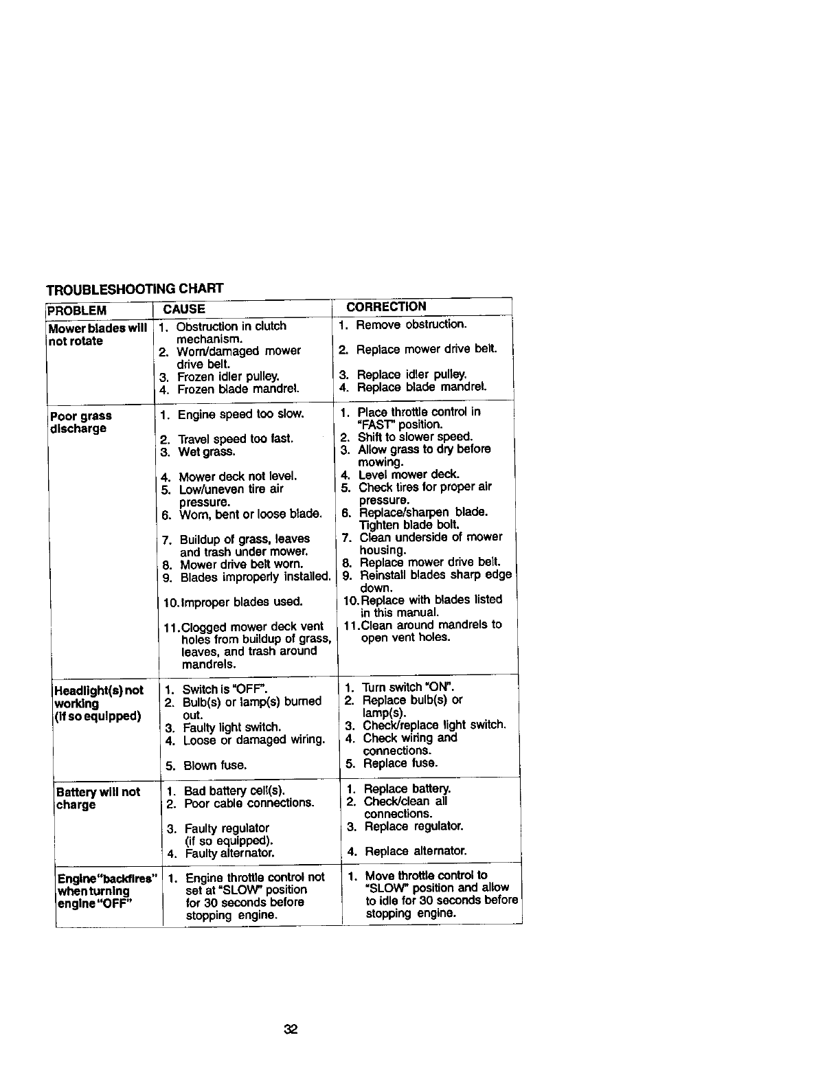
"ROUBLESHOOTING CHART
PROBLEM CAUSE CORRECTION
Mowerbladeawlll 1+ Obstruction in clutch 1, Remove obstruction.
not rotate mechanism.
2. Worn/damaged mower 2. Replace mower ddve belt.
drive belt.
3. Frozen idler pulley• 3. Replace idler pulley.
4. Frozen I_ade mandrel. 4. Replace blade mandrel.
Poor grass 1. Engine speed too slow.
discharge
Headlight(s) not
working
(If so equipped)
2. Travel speed too fast,
3. Wet grass.
. Mowerdecknotlevel
•Low/unevantire air
pressure•
6. Worn,bentor looseblade,
7. Buildup of grass, leaves
and trash under mower.
8. Mower drive belt worn.
9. Blades improperly installed.
10.Improper blades used•
11.Clogged mower deck vent
holes from buildup of grass,
leaves, and trash around
mandrels.
1. Switch is "OFF".
2. Bulb(s) or lamp(s) burned
i3. °F_tultyIJgh!switch.
4. Loose or damaged wiring•
1. Place throttle control in
"FAST" position•
2. Shift to slower speed.
3. Allow grass to dry before
mowing•
4. Level mower deck.
5. Check tires for proper air
pressure.
6. Replace/sharpen blade•
Tighten blade bolt.
7. Clean underside of mower
housing•
8. Replace mower drive belt.
9. Reinstall blades sharp edge
down.
fO.Replace with blades listed
in this manual•
11.Clean around mandrels to
open vent holes•
1. Turn switch "ON".
2. Replace bulb(s) or
lamp(s).
3. Check/replace light switch.
4. Check widng and
connections•
5. Replace fuse.
5. Blown fuse.
Battery will not 1. Bad battery cell(s). 1. Replace battery.
¢hsrge 2. Poor cable connections. 2. Check/clean all
connections.
3. Faulty regulator 3. Replace regulator.
(if so equipped).
4. Faulty alternator. 4. Replace alternator.
Englne"beckllres" 1. Engine throttle control not 1. Move throttle controlto
whenturnlng set at "SLOW" position =SLOW" positionand allow
Dnglne"OFF" for 30 seconds before to idle for 30 seconds before
stopping engine• stopping engine.
32
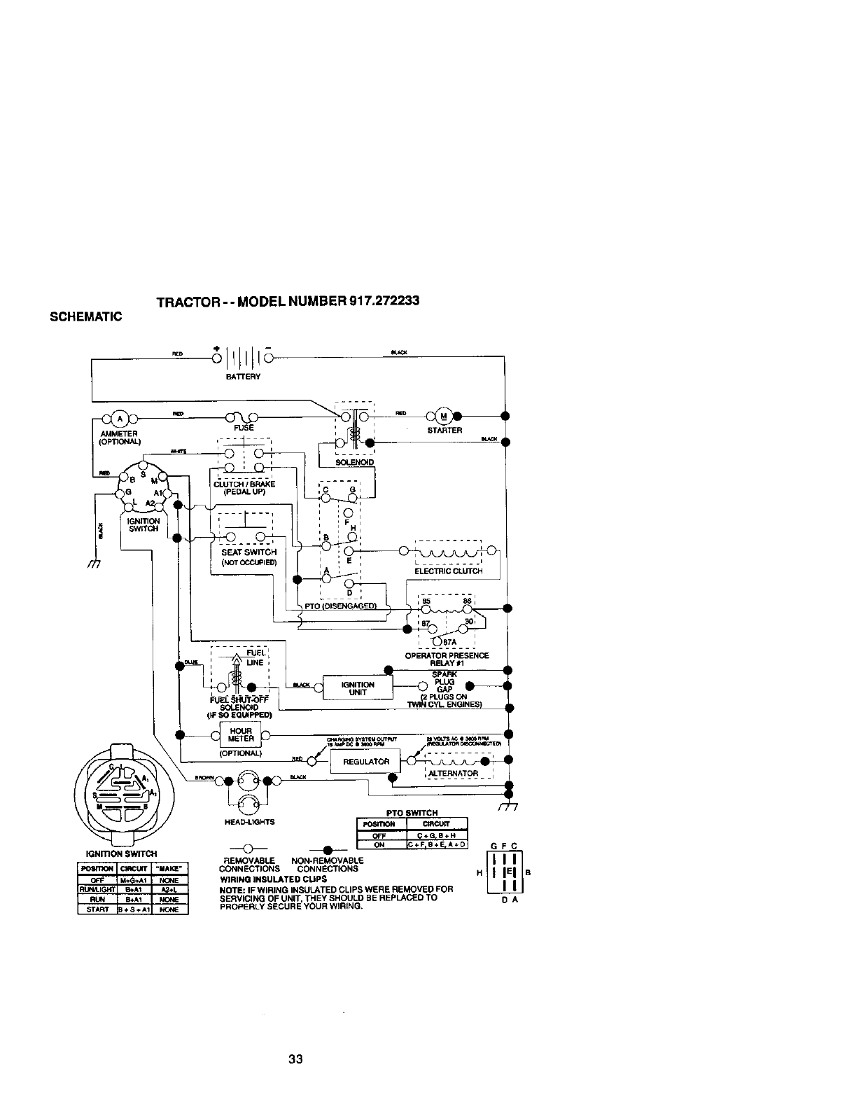
SCHEMATIC TRACTOR --MODEL NUMBER 917.272233
AMMETER
BATTERY
FUSE
IGNmON SWITCH
ii
iFUEL OPERATOR PRESENCE
UNE ARELAY #1 ,
,SPARK '
PLUG
I_IGNITION GAP I_
•....... UNIT PLUGS ON
SOLENOID I "i_llN CYL ENGINES)
(IF SO EQUIPPED)
_SyST_OLrr_w m_L_ I_O0nm
_ • -I__TERNATOR:
PTO SWITCH /_
HEAD-LIGHTS _/ C_'_CUR"
OFF _C÷GIO÷H
ON ÷FIB÷ErA÷D G F C
REMOVABLE NON-REMOVABLE
CONNECTIONS CONNECTIONS H B
WIRING INSULATED CUPS
NOTE: IF WIRING INSULATED CLIPS WERE REMOVEO FOR
SERVICING OF UNIT, THEY SHOULD BE REPLACED TO O A
PROPERLY SECURE YOUR WIRtNG,
33
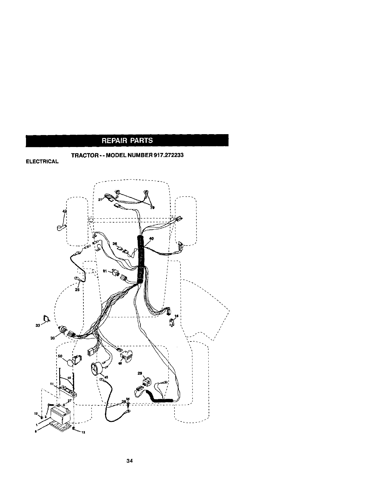
ELECTRICALTRACTOR -- MODEL NUMBER 917.272233
4O
26
34

ELECTRICAL TRACTOR -- MODEL NUMBER 917.272233
KEY PART
NO, NO. DESCRIPTION
1 163465 Battery
2 74760412 Bolt, Hex 1/4-20 x 3/4
8 7603J Tray, Battery
10 145211 Bolt, Btr Front 1/4-20 x 7-1/2
11 150109 Holddown Battery Front Mount
12 145769 Nut, Push NylOn Battery Front 1/4
16 153664 Switch IntedOCkPush-In
21 175449 Harness, Light
25 178909 Cable, Battery
26 175158 Fuse
27 73510400 Nut Kabs Hex 1/4-20 UNC
28 145491 Cable, Ground
29 160784 Switch, Seat
30 175442 Switch, Ignition
33 175447 Key, Molded, Craftsman
40 178452 Harness, Ignition
42 154336 CoverTerminal
45 177500 Ammeter
46 177501 Hourmeter Snap-In
50 178461 Switch Pto 3 Pdt Red Delta
55 17490506 ScrewThdrol 5/16-18x 1/2
67 17750_ PIOConneolor
68 177503 Connector
79 175448 Lamp Assembly
81 109748X ReleyAsm
NOTE: All component dimensions given in U.S. inches
1 inch =25.4 mm
35
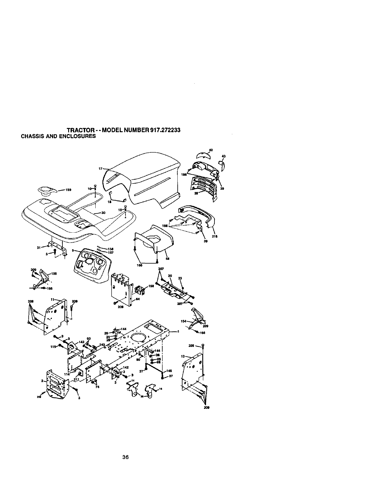
TRACTOR - - MODEL NUMBER 917.272233
CHASSISAND ENCLOSURES
42
29
2O9
36

TRACTOR --MODEL NUMBER 917.272233
CHASSIS AND ENCLOSURES
KEY PART
NO. NO. DESCRIPTION
I174619 Chassis
2 176554 Draw_zr
3 17060612 Screw, 3/8-16 x 3/4
9 17_542X418 Da_
10 $I_o3_710 Bolt, Cardage 3/8-16xi
11 174996 Panel, Dash, LH
13 179174X010 Panet, Dash, RH
14 17490608 Screw Thdrol 3/8-16 x 1/2
17 172540X615 Hood LTX
18 1L_938X Bumper Hood
20 156437 Plate Batted/STYT
23 124028X Bushing Snap
25 19131312 Washer 13/32 x 13/16 x 12 Gauge
26 STC641437 Locknut. Hex, with Insert 3/8-16 UNC
28 174945X418 Gr;lle,MS-558
28 174944X418 Light Box, Dual
30 175692X615 Fender/Footrest
31 139976 Bracket, FendedSuppOd
37 17490506 Screw, Thdrol. 5;16-18 x 1/2 TYT
28 175710 Bracket Asm Pivot Mower Rear
39 174988 Bracket Pivot Hood LTX
42 172545X599 Lens LH
43 172544X599 Lens RH
58 174993 Duct Hood
60 $1_533707 BoltRdhd Sqnk3i8-16UNCx3/4
64 174997 Dash Lower STYT
74 STD541437 Nut Crownlock 3/8-16 UNC
t14 158112 Keeper Beit Rear Lh STL
115 17060620 Scew 3/8-16 x 1-1/4
142 1757_2 Plate Reinforcement STLT
143 154966 BraCket Swaybar Chassis
144 175582 Bracket Footrest STLT
145 156524 Rod Pivot Chassis/Hood
154 174679 Bracket Dash Rh
155 174680 Bracket Dash Lh
156 163805 Stdker Plate
157 163806 Magnet YTGT
158 162G37 Parking Btllke Blur
159 155123X418 CupholderStlBIk
166 164863 HWHDH:-Lo. #13-16x 3/4
206 170165 Boit Shoulder 5/16-18
207 17670506 Screw Thdrol 5/16-18 x 1/2
209 1701X)612 Screw Hexwsh Tndr 3,'8-16 x 3/4
211 145212 Nut Hexflange Lock
215 172543X615 Bul'tlpe¢
NOTE: All component dimensions given in U.S. inches
1 inch ,- 25.4 mm
37
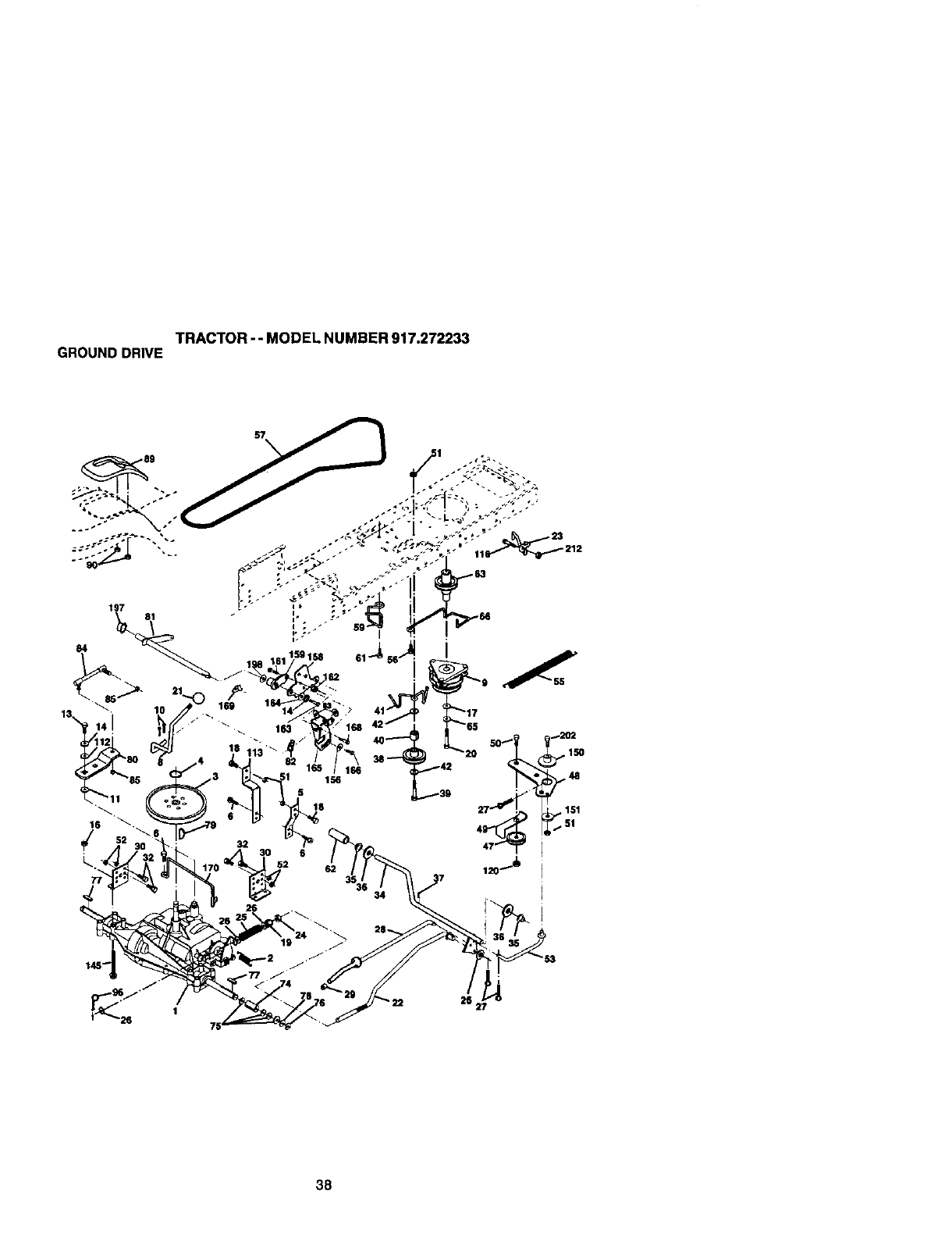
TRACTOR -- MODEL NUMBER 917.272233
GROUND DRIVE
163
156
5
18
38
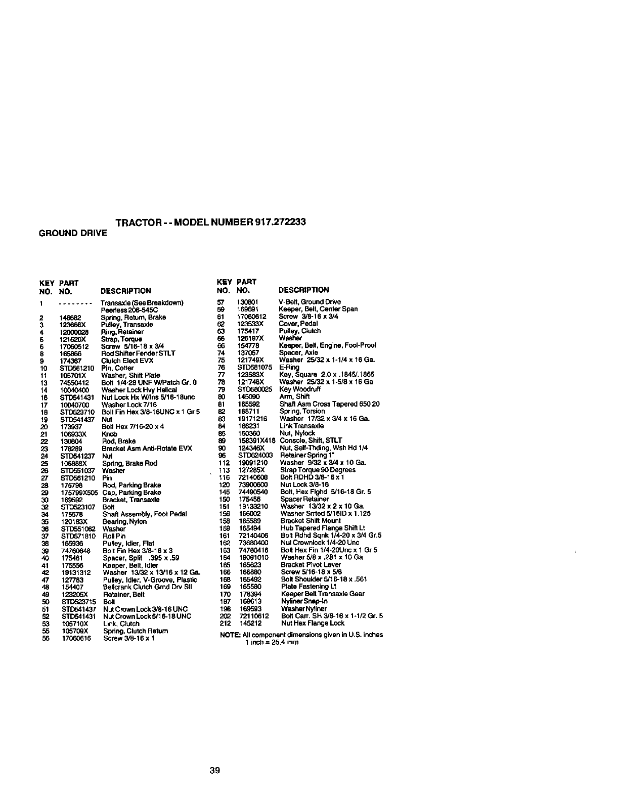
TRACTOR --MODEL NUMBER 917.272233
GROUNDDRIVE
KEY PART KEY PART
NO, NO, DESCRIPTION NO. NO. DESCRIPTION
1........ Transa)de (See Breakdown) 57
Peedess 206-545C 59
2 146682 Spring, Retum, Brake 61
3 123666X Pulley, Tmnsaxle 62
4 1_ Ring, Retainer _3
5 121520X Strap, TOn:lira 66
6 17060512 Screw 5/16-18 x 3/4 66
8 165866 Rod Shifter Fender S1].T 74
9 174367 Clutch Elect EVX 75
10 _1210 Pin, Cotter 76
11 1(_5701X Washer, Shift Plate 77
13 74550412 Bo_t 1/4-28 UNF W/Patch Gr. 8 78
14 10040400 Washer Lock Hvy Helical 79
16 STD641431 Nut Lock Hx W/Ins 5/16-18unc 80
17 10040700 W_sher Lock 7/16 81
18 STD523710 Bolt Fin Hex 3/6-16UNC x 1 Gr 5 82
19 STC541437 Nut 83
20 173937 Bolt Hex 7/16-20 x 4 84
21 106_3X Knob 85
22 130804 Rod, Brake 89
23 178289 Bracket Asm Anti-Rotate EVX 90
24 STC641237 Nut 96
25 106_88X Spdng, Brake ROd 112
26 STD5510_7 Washer 113
27 STD561210 Pin 116
28 175798 Rod, Parking Brake 120
29 175799_ Cap, Parking Brake 145
30 169592 Bracket, Transaxle 150
32 STC623107 Bolt 151
34 175578 Shaft Assembly, Foot Pedal 156
35 120183X Bearing,Nylon 158
36 STD551_ Washer
37 $10571810 Roll Pin
38 165936 Pulley, Idler, Flat
39 7476(To48 Bolt Fin Hex 3/6-16 x 3
40 175461 Spacer, Split .395 x ,59
41 175556 Keeper, Bolt, Idler
42 19131312 Washer 13/32 x 13/16 x 12 Ga.
47 127783 Pulley, taler, V-Groove, Plastic
48 154407 Bellcrenk Clutch Gmd Dry Stl
49 123_05X Retainer, Belt
50 $1_;_3715 Bolt
51 S'rD541437 Nut Crown Lock 3/8-16 UNC
52 S'RT_41431 Nut Crown Lock 5/16-18 UNC
53 105710X Link, Clutch
56 105709X Spring, Clutch Return
56 17060616 Screw 3/6-16 x 1
130801 V-Belt, Ground Drive
169691 Keeper, Belt, Center Span
17060612 Screw 3/6-16 x 3/4
123533X Cover, Pedal
175417 Pultey, Clutch
126197X Wach_
154778 Keeper, Bolt, Engine, Fool-Proof
137057 Spacer, Axle
121749X Washer 25/32 x 1-1/4 x 16 Ga.
STD581075 E-Ring
123583X Key, Square 2.0 x .1845/.1865
121748X Washer 25/32 x I-5/8 x 16 Ga
Key WoodnJff
145090 Arm, Shift
165592 Shaft Asm Cross Tapered 650 20
165711 Spring, Torsion
19171216 Washer 17/32 x 3/4 x 16 Ga.
166231 Link Transaxle
150360 Nut, NyIOCk
158391X418 Console, Shift, STLT
124346X Nut, Self-Thding, Wsh Hd 1/4
S'[D624003 Retainer Spring 1"
19091210 Washer 9i32 x 3/4 x 10 Ga.
127285X Strep Torque 90 Degrees
72140606 Belt RDHD 3/6-16 x 1
739006(_ Nut Lock 3/6-16
74490540 BOg,Hex Flghd 5/16-18 Gr. 5
175456 Spacer Retainer
19133210 Washer 13/32 x 2 x 10 Ga.
1660(;2 Wa.sher Srdod 5/161D x 1.125
165589 Bracket Shift Mount
159 165494 Hub Taperod Range Shift Lt
161 72140406 Bolt Rdhd Sqnk 1/4-20 x 3/4 Gr.5
162 73680400 Nut Crowninck 1/4-20 Unc
163 74780416 BoltHexFinl/4-20Uncxl Gr5
164 19091010 Washer 5/8 x .281 x 10 Ga
165 165623 Bracket Pivot Lever
166 166880 Screw 5/16-18 x 5/8
168 165492 BO9 Shoulder 5/16-18 x.561
16_ 165580 Plate Fastening Lt
170 178394 Keeper BOlt Transaxle Gear
197 169613 Nyliner Snep-ta
1_ 169593 Washer Nyflner
2_ 72116612 Bolt Carr. SH 3/8-16 x 1-1/2 Gr. 5
212 145212 Nut Hex Flange Lock
NOTE: All component dimensions given in U.S. inches
1 inch = 25.4 mm
39
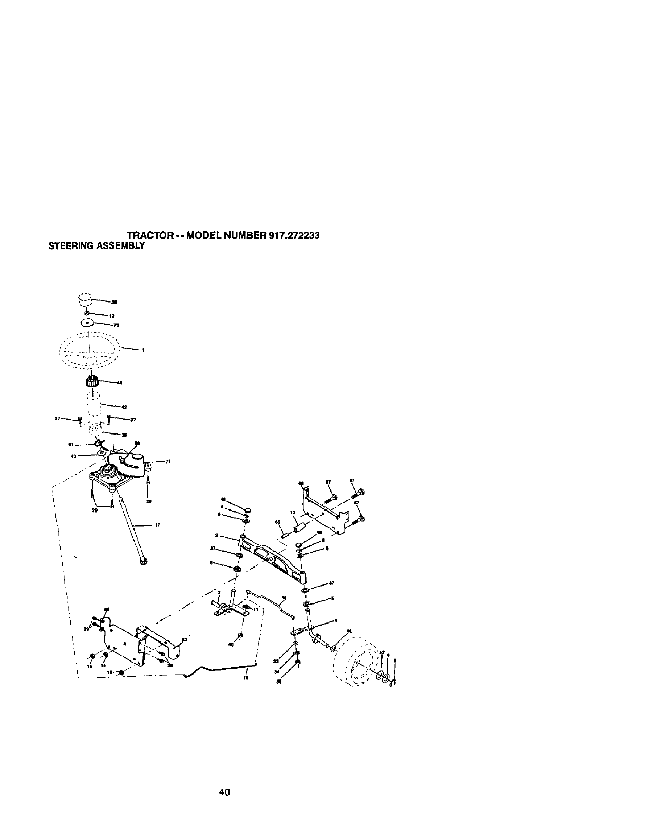
TRACTOR -- MODEL NUMBER 917.272233
STEERINGASSEMBLY
•..222J2222 -.
4O
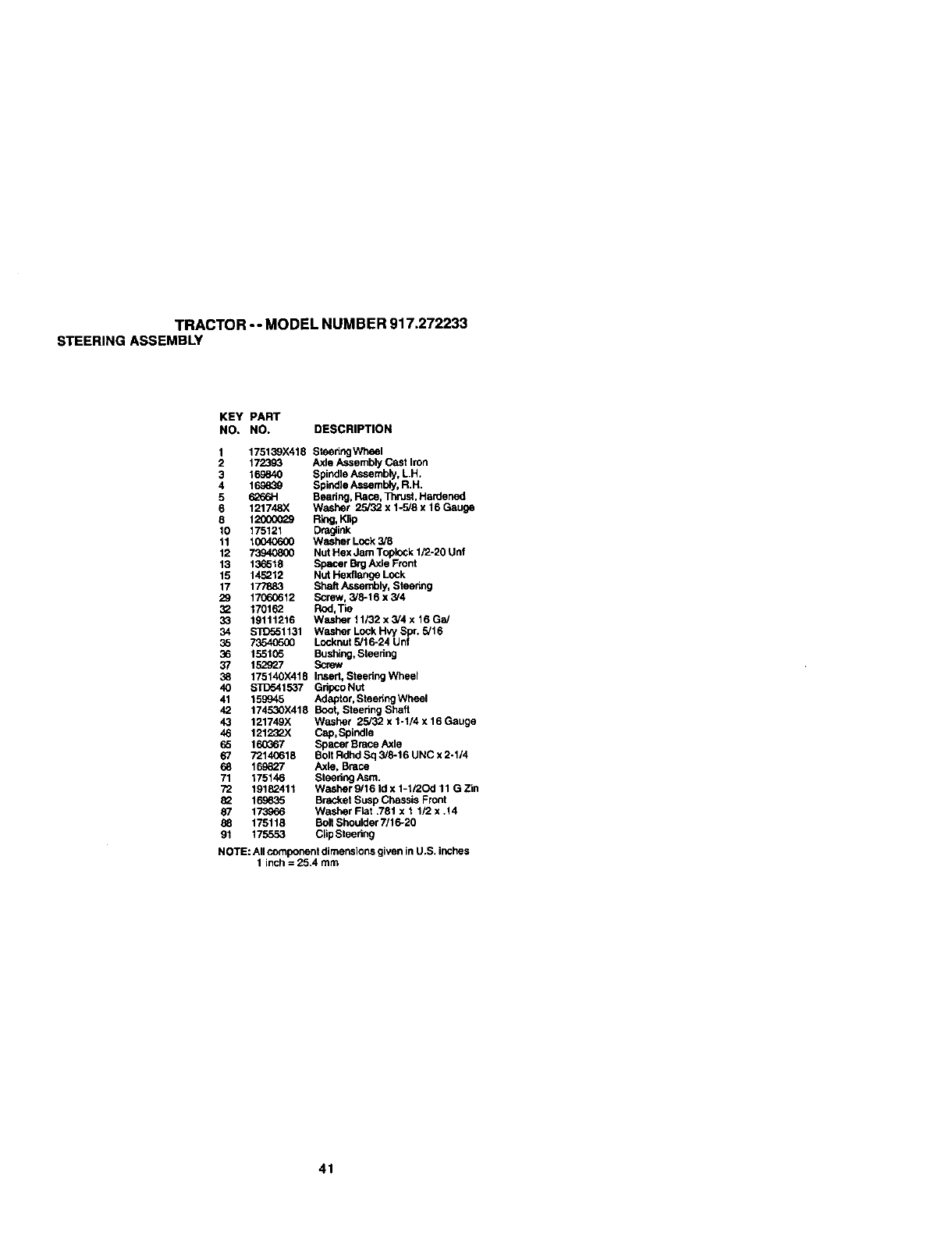
TRACTOR -- MODEL NUMBER 917.272233
STEERINGASSEMBLY
KEY PART
NO. NO. DESCRIPTION
1 175139X418 Steering Wheel
2172393 Axle Assembly Cast Iron
3 16_840 Spindle Assembly, LH.
4 16_39 Spindle Assembly, R.H.
5 62661-1 Beadng, Race, Thrust, Hardened
6 121748X Weshar 25/32 x 1-5/8 x 16 Gauge
8 1200(X_9 Ring, K5p
10 175121 Draglink
11 10040600 Washer Lock 318
12 73940800 Nut Hex Jam Toplock 1/2-20 Unf
13 13_518 Spacer Brg Axle Front
15 145212 Nut Hexflange Lock
17 177883 Shaft Assembly, Steering
29 17060612 Screw, _/8-16 x 3/4
32 170162 Rod,Tie
33 19111216 Washar 11/32 x 3/4 x 16 Ga/
34 $31_51131 Washer Lock HW Spr. 5/16
35 73540500 Locknut 5/16-24 Unf
36 155105 Bushing,Steering
37 152927 Screw
38 175140X418 Insert, Steedng Wheel
40 STD541537 Gripco Nut
41 159945 Adaptor, Steering Wheel
42 174530X418 Boot, Steering Shaft
43 121749X Washer 25/32 x 1-1/4 x 16 Gauge
46 12123_X Cap,Spindle
65 160G67 Spacer Brace Axle
67 7214G618 Bolt Rdhd Sq 3/8-16 UNC x 2-1/4
68 169827 Axle, Brace
71 175146 Steering ASm.
72 19182411 Washer 9/16 Id x 1-1/2Od 11 G Zin
82 169635 Bracket Susp Chassis Front
87 173966 Washer Fiat .781 x 11/2 x .14
88 175118 Bolt Shoulder 7/16-20
91 175553 ClipSteering
NOTE: All component dimensio_ given in U.S. inches
1inch = 25.4 mm
41
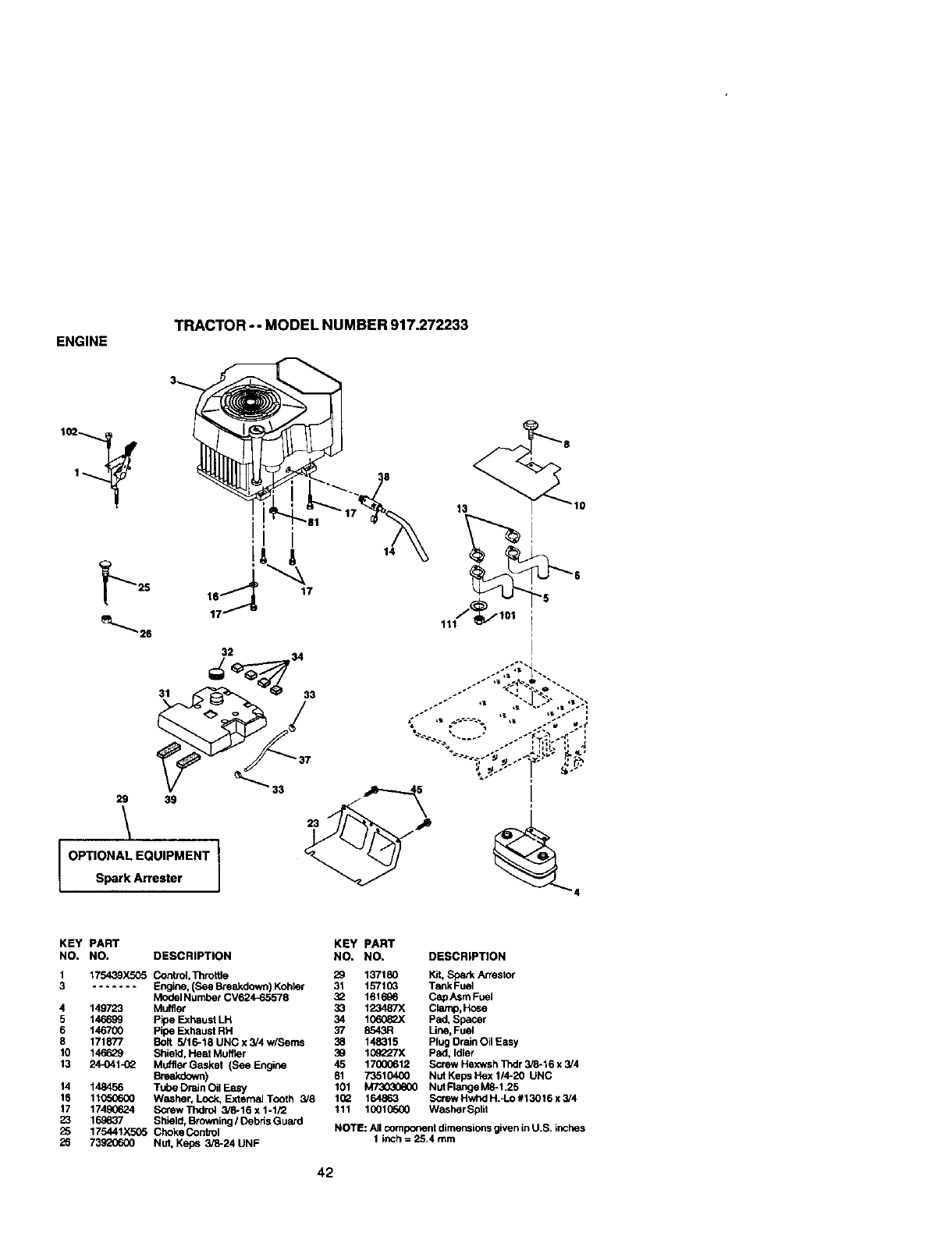
ENGINE TRACTOR -- MODEL NUMBER 917.272233
14
'i
OPTIONAL EQUIPMENT
Spark Arrester
13
...- ,, ,,-J...",,,;...
-" ,I
I
KEY PART KEY PART
NO. NO. DESCRIPTION NO. NO. DESCRIPTION
1 175439X505 Control,Throttle 29 137180 Kit, Spark Arrestor
3....... Engine, (See Breakdown) Kohler 31 1571G3 Tank Fuel
Model Number CV624_5578 32 161696 CapAsm Fuel
4 149723 Muffler 33 123487X Clamp,Hose
5 146699 Pipe Exhaust LH 34 106082)( Pad, spacer
6 146700 Pipe Exhaust RH 37 8543R Line, Fuel
8 171877 Bolt 5,'16-18 UNC x 3/4 w/Seres 38 148315 Plug Drain Oil Easy
10 146629 Shield, Heat Muffler 39 109227X Pad, Idler
13 24-041 -(_ Muflter Gasket (See Engine 45 17000612 Screw Hexwsh Thdr 3/8-16 x 3/4
Breakdown) 81 73510400 Nut Keps Flex 1/4-20 UNC
14 148456 Tube Drain Oil Easy 101 M73030600 Nut Flange M8-1.25
16 11G506_) Washer, Lock, External Tooth 3/8 102 164863 Screw Hwhd H.-Lo #13016 x 3/4
17 17490624 Screw Thdrol 3/8-16 x 1-1/2 111 1001(_o00 Washer Spilt
23 169837 Shield, Browning /Oebds Guard
25 175441X505 Choke Control NOTE: All component dimensions given inU.S. inches
26 73920600 NUt, Keps 3/8-24 UNF 1 inch =25.4 mm
42
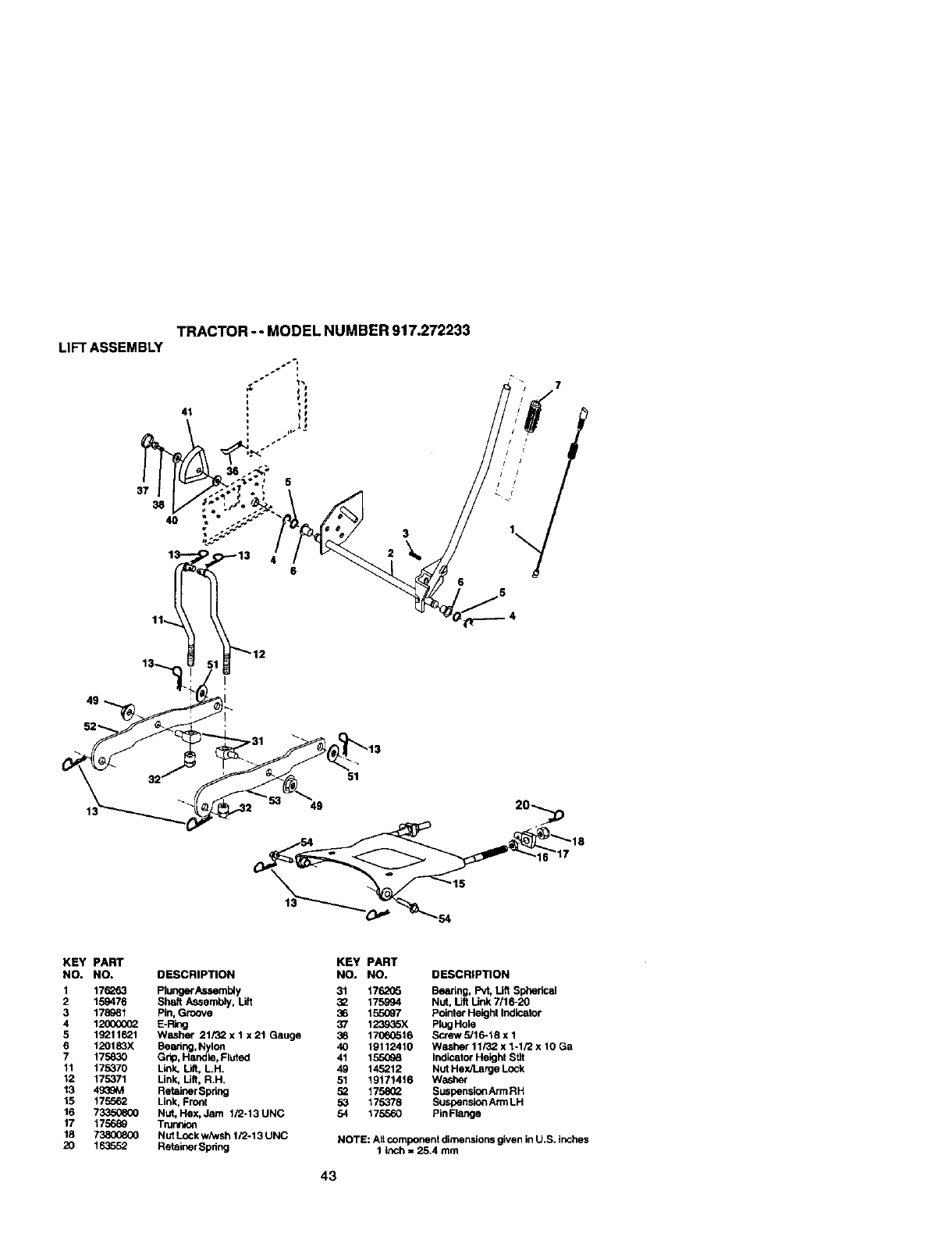
LIFTASSEMBLY
49
TRACTOR -- MODEL NUMBER 917.272233
,+ !i
41 : ;i
37
38
40
1 13 4
11
12
13
3
6
51
49
KEY PART
NO. NO.
1 176_53
2 159476
3 178981
4 120000(_
5 19211621
6 120183X
7 175830
11 175370
12 175371
13 493gM
15 175562
16 7335(_(_
17 175_89
18 73800800
2O 163552
DESCRIPTION
Plunger Assembly
Shaft Assembly, Lift
Pin, Groove
E-Ring
Washer 21/32 x 1 x 21 Gauge
Beadng, Nylon
Grip, Handle, Fluted
Link Lift, LH.
Unk, Uft. R.H.
Retainer Spring
Link, Front
Nut, Hex, Jam 1/2-13 UNC
TmrtnK_
Nut Lock wiwsh 1/2-13 UNC
Retainer Spdng
KEY PART
NO. NO. DESCRIPTION
31 176205 Beanng, Pvt, Uft Spherical
32 175994 Nut, lift Unk 7/16-20
36 155097 Poinler Height Indicator
37 123935X Plug Hole
38 17_16 Screw 5/16-18 x 1
40 19112410 Washer 11/32 x 1-1/2 x 10 Ga
41 1_ Indicator Height St]t
49 145212 Nut Hex/Large Lock
51 19171416 Washer
52 1758_Z Suspens_onArm RH
53 175378 Suspension Arm LH
54 175560 Pin Flange
NOTE: AlLcomponent dimensions given in U.S. inches
1 inch =25.4 mm
43
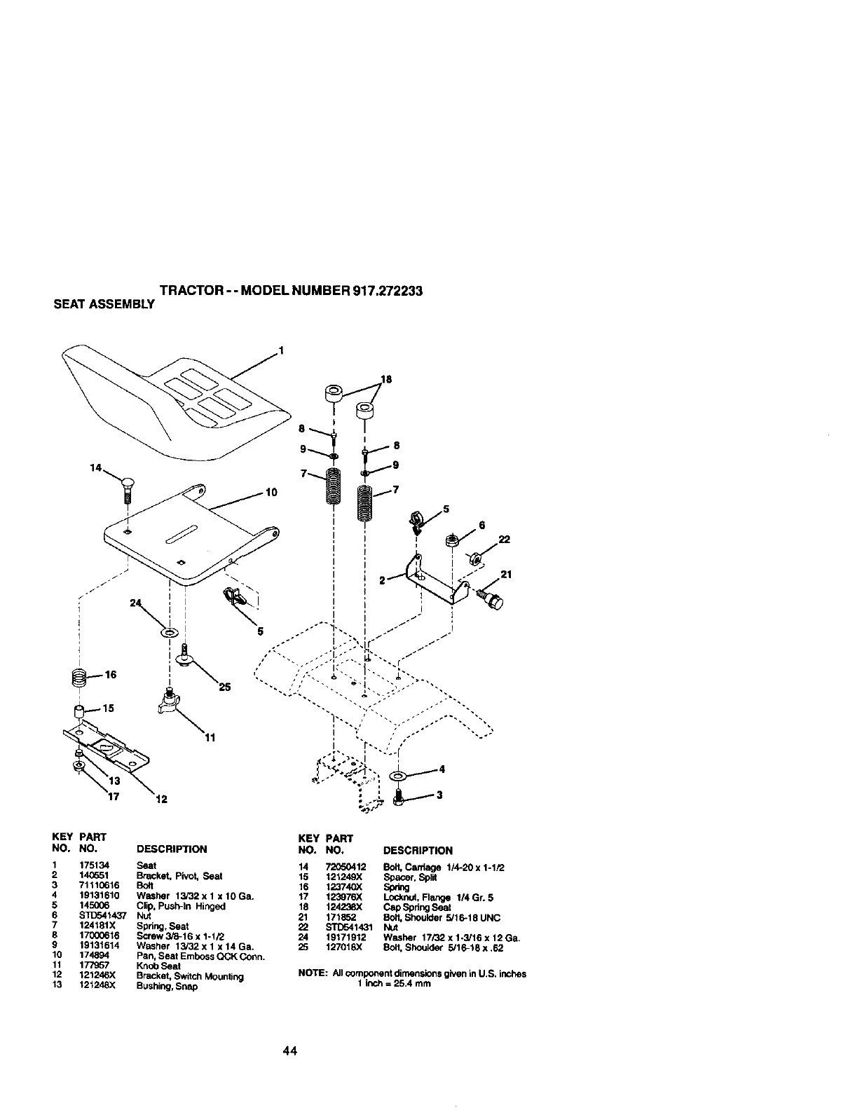
TRACTOR -- MODEL NUMBER 917.272233
SEATASSEMBLY
KEY PART
NO, NO. DESCRIPTION
1 175134 Seat
2 14_651 Bracket, Pivot, Seat
3 71110616 Bolt
4 19131610 Washer 13/32 x 1 x 10 Ga.
5 145006 Clip, Push-In Hinged
6 $11To41437 Nu_
7 124181X Spring, Seat
8 17000616 Serew 3/8-16 x 1-1/2
9 19131614 Washer 13/32 x 1 x14 Ga.
10 174894 Pan, Seat Emboss QCK Conn.
11 177957 Knob Seat
12 121246X Bracket, Switch Mounting
13 121248X Bushing, Snap
KEY PART
NO. NO. DESCRIPTION
14 _12 EOH, Can';age 1/4-20 x 1-1/2
15 121249X Space_, Split
16 123740X Spdng
17 123976X Loc_nut, Range 114Gr. 5
18 124238X Cap Spdng Seat
21 171852 Bolt, Shoulder 5/16-18 UNC
22 STD541431 Nut
24 19171912 Washer 17/32 x 1-3/16 x 12 Ga.
25 127018X Bolt, Shoulder 5/16-13x.62
NOTE: All component dimensions given in U.S. inches
1 inch = 25.4 mm
44
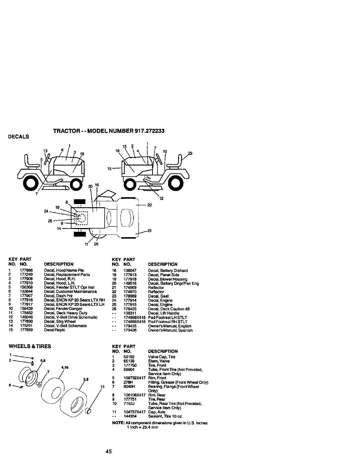
DECALS
7
TRACTOR --MODEL NUMBER 917.272233
12
KEY PART
NO. NO.
1177888
2 177249
3 177909
4 177910
5 156368
6 133644
7 177967
8 177916
9 177917
10 156439
11 178482
12 146046
13 177890
14 175291
15 177889
DESCRIPTION
Decal, Hood Name Pie.
Decal, Repl_.ernent Parts
Decal, Hood, R.H.
Deca_. Hood. LH.
Decal. Fender STLT Opr Inst
Decal, Customer Mainter_nce
Decal, Dash Pnl
Decal, ENCN KP 20 Sears LTX RH
Decal, ENCN KP 20 Sears LTX LH
Decal, Fender Danger
Decal, Deck Heavy Duty
Decal, V-Belt Ddve Schematic
Decal, Strg Wheel
Decal, V-Belt Schematic
Decal Replc
KEY PART
NO. NO. DESCRIPTION
16 138047 Decal. Battery Diehard
18 177913 Decal. Panel Side
19 177918 Decal. Blower Housing
20 149516 Decal, Battery Dngr/Psn Eng
21 174969 Reflect_
22 174970 Reflector
23 178..o69 Decal, Seat
24 177914 Decal, Engine
25 177915 Decal, Engine
26 178455 Decal, Deck Caution 48
- - 138311 Decal, LiftHandle
*- 174898X418 Pad Footrest LH STLT
-- 174999X418 Pad Footrest RH STLT
-- 179435 Owners Manual, English
-- 179436 Owner's Man ual, Spanish
WHEELS &TIRES
2_5,8 4,10
11
KEY PART
NO. NO. DESCRIPTION
1 591S2 Valve Cap, Tire
2 65139 Stem. Vak'e
3 177750 Tim, Front
459904 Tube, Front Tim (Not Provided,
Sen, ice Item Only)
5 106"F_.X417 Rim, Front
6278;-I F'_ing, Grease (Front Wheel Only)
79040H Searing, Flange (Front Wl_eel
8 106108X417 Rim, Rear
9 177751 ]3re,Rear
10 7152J Tube. Rear Tire (Not Provided,
Senlice Item Only)
11 104757X417 Cap. Axle
- - 144334 Sealent, Tire 10 oz.
NOTE: A_ component dimensions given in U.S. inches
I inch = 25.4 mm
45
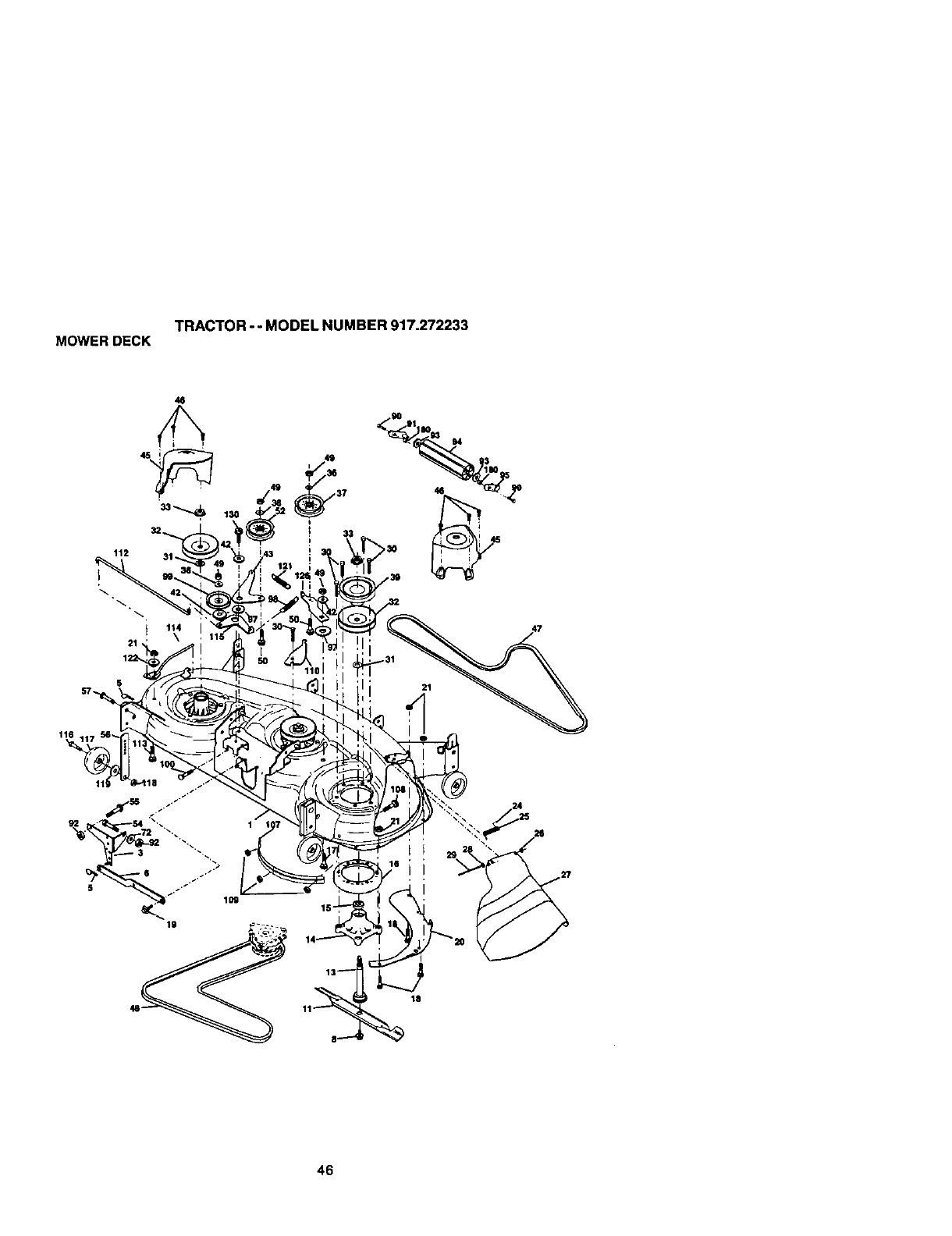
TRACTOR - - MODEL NUMBER 917.272233
MOWERDECK
46
112
S
18
46
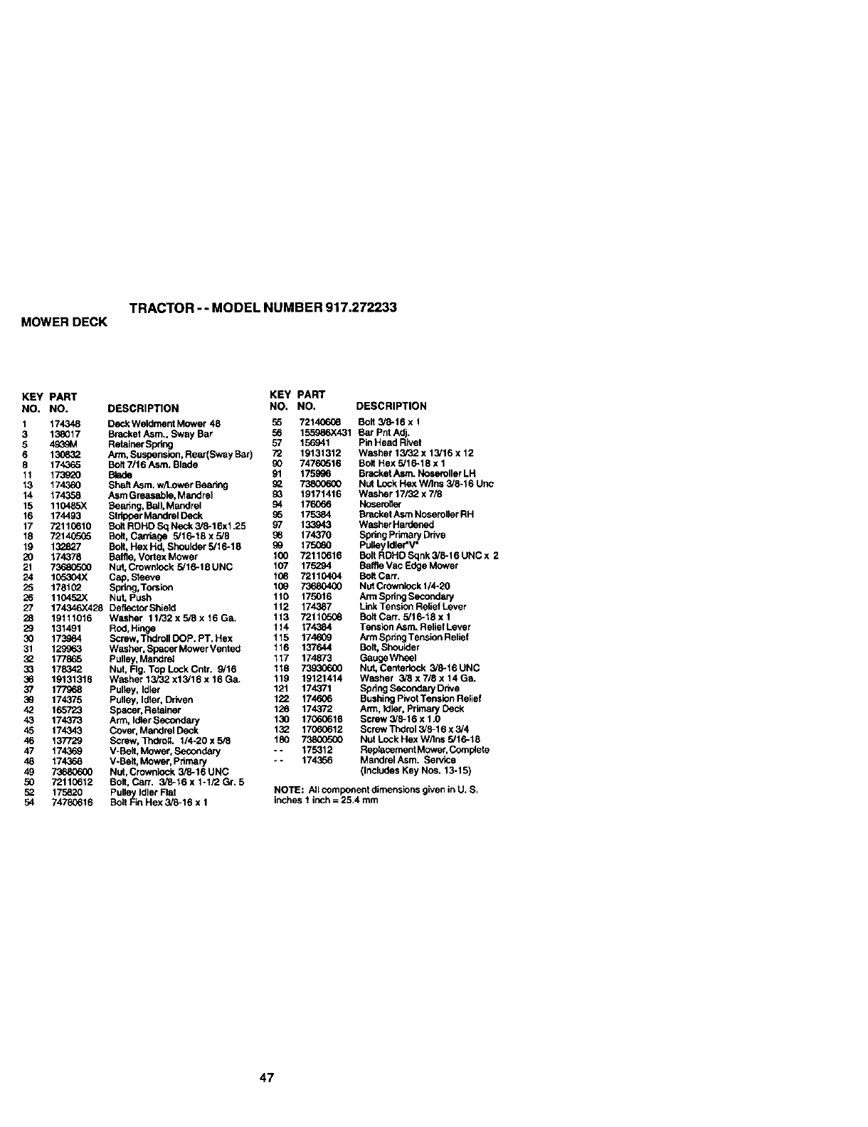
TRACTOR -- MODEL NUMBER 917.272233
MOWERDECK
KEY PART KEY PART
NO. NO. DESCRIPTION NO. NO. DESCRIPTION
1174348 DeckWeldment Mower 48 r_ 72140608 Bolt 3/8-16 x 1
3 138017 Bracket Asm., Sway BOr 56 155986X431 Bar Pnt Adj.
5 4_,,! Retainer Spdng 57 156941 Pin Head Rivet
6 130632 Arm, Suspension, Rear(Sway Bar) 72 19131312 Washer 13/32 x 13/16 x 12
8 174365 BOlt 7/16 Asm. Btade 90 74760516 Bolt Hex 5/18-18 x 1
11 173920 Blade 91 175._6 Bracket Asm. Noseroller LH
13 174360 Shaft Asm. w/1J:)werBearing 92 73800600 Nut Lock Hex W/Ins 3/8-16 Uric
14 174358 Asm Greasaple, Mandrel 93 19171416 Washer 17/32 x 7/8
15 110485X Boadng, Ball, Mandrel 94 1760_5 NoseroNef
16 174493 Stdpper Mandrel Deck _5 175384 Bracket Asm Noseroller RH
17 72110610 Bolt ROHD Sq Neck 3/8-16xl.25 97 133943 Washer Hardened
18 7214C505 Bolt, Carriage 5/16-18 x 5/8 39 174370 Spdng Primary Ddve
19 132.827 Bolt, Hex Hd, Shoulder 5/16-18 g9 17.5060 Pulley Idler'V"
20 174378 Baffie, Vortex Mower 100 72110616 BOItRDHDSqnk3/8-16UNCx 2
21 739305G0 NUt, Crownleck 9/16-18 UNC 107 175294 Baffta Vac Edge Mower
24 105304X Cap, Sleeve 139 72110404 Bolt Can'.
25 178102 Sprlng,Torsion 109 73680400 Nut Crownlock 1/4-20
26 110452;( Nut, Push 110 175016 Arm Spdng Secondary
27 174346X428 DefiectorShield 112 174,387 LinkTensionReliefLever
28 19111016 Washer 11i32x5/8x16Ga. 113 7211C5(_ BudCarr. 5/16-18x1
29 131491 Rod,Hinge 114 174384 TenSion Asm. Relief Lever
30 173984 Screw, Thdroll DOP. PT. Hex 115 174609 Arm Spdng Tension Relief
31 129963 Washer, Spacer MowerVented 116 137644 Bolt, Shoutder
:_ 177865 Pulley, Mandrel 117 174873 GaugeWheel
33 178342 Nut, FIg. Top Lock Cntr. 9/16 118 _Nut, Centerlock3/8-16UNC
36 19131316 Washer13/32x13/16x16Ga. 119 19121414 Washer 3i8x7/8x14Ga.
37 177968 Pulley, Idler 121 174371 SpdngSecondaryDdve
39 174375 Pulley, Idler, Driven 122 174606 Bushing PivotTension Relief
42 165723 Spacer, Retainer 126 174372 Arm, _er, Primary Deck
43 174373 Arm, IdlerSecondary 130 17060616 Screw 3/8-16 x 1.0
45 174343 Cover, Mandrel Deck 1_ 17060612 Screw Thdrol 3/8-16 x 3/4
46 137729 Screw, Tndro;. 1/4-20x5_ 180 738CO500 NutLockHexW/Insg/16-18
47 174369 V-Belt, Mower, Secondary - - 175312 Rap_cement Mower, Complete
48 174368 V-Belt, Mower, Primary - - 174356 Msndrel Asm. Service
49 73680600 Nut, Crownleck 3/8-16 UNC (Includes Key Nos. 13-15)
50 72110612 Bolt, Can. 3/8-16 x 1-1/2 Gr. 5
52 175820 Pulley Idler Flat
54 74793616 Bolt Fin Hex 3/8-16 x 1
NOTE: All component dimensions given in U. S,
inches 1 inch = 25.4 mm
47
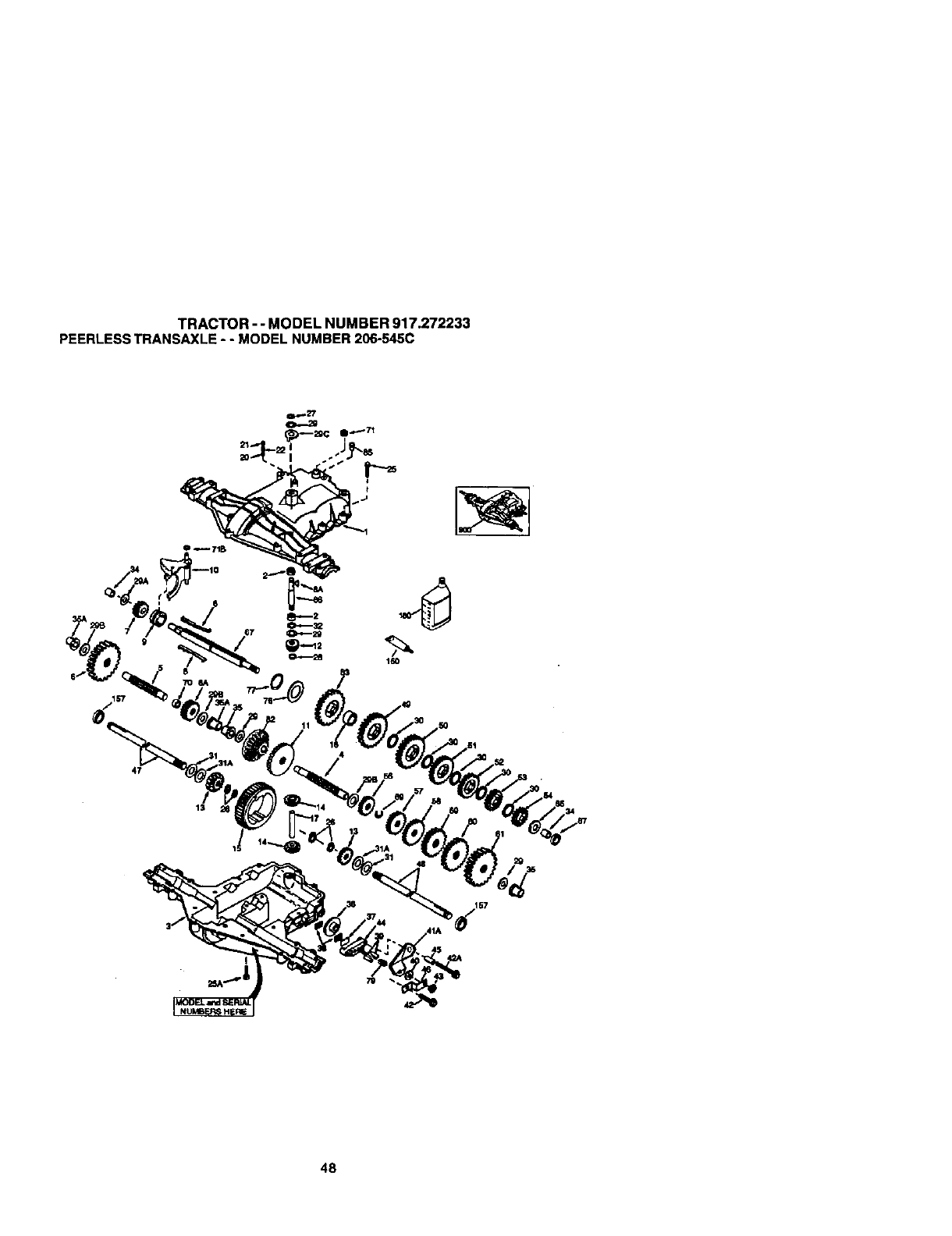
TRACTOR - - MODEL NUMBER 917.272233
PEERLESSTRANSAXLE- - MODEL NUMBER206-545C
160
13
48

TRACTOR -- MODEL NUMBER 917.272233
PEERLESSTRANSAXLE-- MODEL NUMBER 206-545C
_EY PART I_Y PART
NO, NO. DESCR_ NO. NO. DESCRIPllOH
1 772147 Transaxio Cover 41A 790079 BraiseLever
2 780(_6A Nee(lid Bearing 5/6, 42 792073A Screw 1/4 -20 x 1-1/4"
3 770128 T_leCase 42A 792085A Screw 1/4 - 20 x 21/4"
4 776395 Countershaft 43 792075 Locknut 5 /16 - 24
5 776409 Output Shaft 44 790025 Brake Pad Holder
6 778364 Spu/Gear (38 teeth) 45 786066 Spacer .2625 x 1.0
6A 778369 Spur Gear (15 teeth) 46 786066 Brake Lever Bracket
7 778330 Spur Gear (11 teeth) 47 774690 Axle (11-15 /16" Long)
8 792180 Shift Key 48 774691 Axle (t 6 -1/2" long)
8A 792047 Woodruff Key #9 49 778356 Spur Gear (29 teeth)
9 784352 Shift Collar 50 778338 Spur Gear (27 teeth)
10 784378 Shift Rod & Fork 51 778354 Spur Gear (23 teeth)
11 778334 Beval Gear (30 teeth) 52 778.352 Spur Gear (19 teeth)
12 778309 Input Bevel Pinion (13 teeth) 53 778350 Spur Gear (16 teeth)
13 778368 Bevai Gear (13 teeth) (thchide,14) 54 778346 Spur Gear (15 teeth)
14 778368 Bevel Pinion(13 teeth)(Incidde.t 3) 56 778355 Spur Gear (11 teeth)
15 778370 Ring Gear (43 teeth) 57 778337 Spur Gear ( 13 teeth)
17 786188 Drive Pin 58 778,353 Spur Gear (17 teeth)
18 786102 Spacer 1.130X .695 59 778351 Spur Gear (21 teeth)
20 792077A Ball 5/1 6" dia 60 778349 Spur Gear (24 teeth)
21 792078 Set Screw 3/8 -16 x 3/6" 61 778345 Spur Gear (25 teeth)
22 792079 Spring .310 OD x .625 L 65 780189 Rat Washer .563 ID x .062W
25 792073A Screw 1/4 - 20 x %1/4" 66 776422 Input Shaft
25A 792177 Screw 1/4-20 x t -3/8" 67 776396 Shifter & Brake Shaft
26 792125 Retaining Ring (pkg of 2) 69 792170 Retaining Ring
27 792035 Rutainidg Ring 70 786187 Spacer .890
28 788040 Retainidg Ring 71 788069 Square Cut Ring
29 780072 Thrust Washer .627 ID x ,031W 71B 788092 "O"Ring
29A 780160 Thrust Washer .762 ID x ,031W 76 780090 Flat Washer 1.128 ID x ,058W
29B 780051 Thrust Washer .762 ID x .031W "/7 788078A Inverted Retaining Ring
29C 780199 Anti-Rotation Washer .632 79 792144 Spring .430 OD x .5000 L
30 780108 Cup Washer 1,127 ID x .032W 82 778333 Bevel & Spur Gear (30 & 13 teeth)
31 780001 Rat Washer .750 ID x .056W (Use 83 778338 Spur Gear (27 teeth)
ASNeeded) 85 792154 Oil FillPlug
31A 780155 Rat Washer .750 IO x .062W 87 788089A Oil Seal 9 /16"
32 788083 Oil Seal 5/8' 150 78809_A Liquid Gasket RTV Silicone
34 780194 Bushing .563 157 788088A Oil Seal 3/4"
35 780193 Flangad Bushing 5 /8" ID 180 73(_29A Gear Oil 80W90
35A 780197 F]sngedBushing.751 !_0 794712 ReplacementMST-206-545C
36 790075 Brake I_isk Transaxle
37 790007 Broke Pad Plate
38 799a21 Brake Pad (pkg of 2)
39 786_ E_,el Pin NOTE: All component dimensions given in U.S. inches
40 792076A Rat Washer ,312 ID x .059W 1 inch =25.4 mm
49
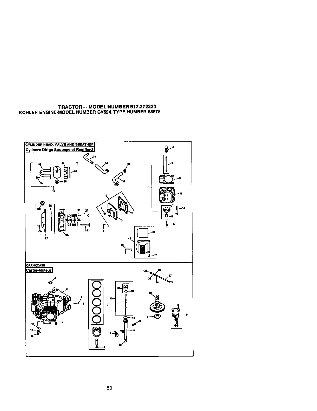
TRACTOR -- MODEL NUMBER 917.272233
KOHLERENGINE-MODELNUMBER CV624,TYPE NUMBER65578
I
7-- _111
|
5O
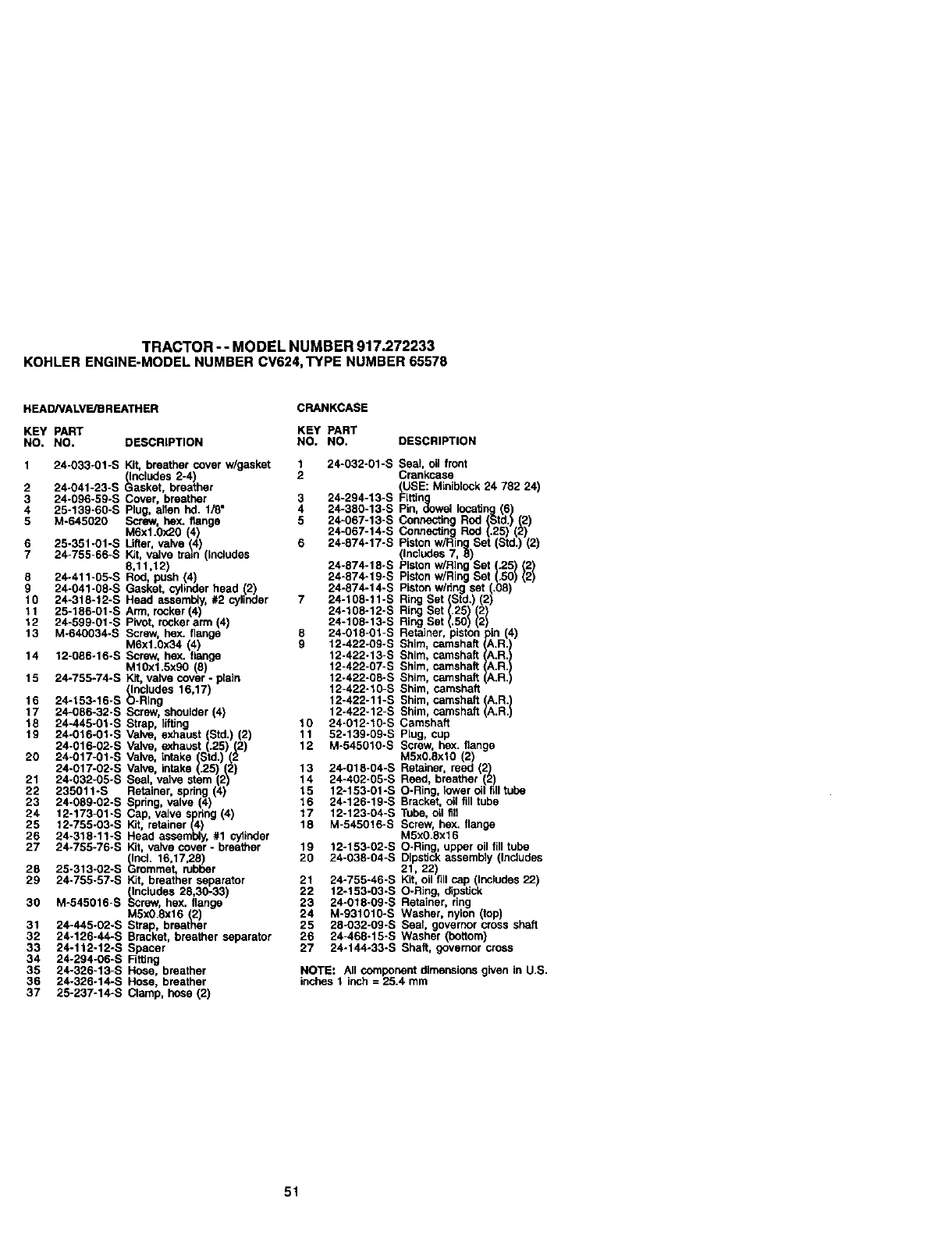
TRACTOR -- MODEL NUMBER 917.272233
KOHLERENGINE-MODELNUMBER CV624,TYPE NUMBER 65578
HEAD/VALVE/DREATHER CRANKCASE
KEY PART KEY PART
NO. NO. DESCRIPTION NO, NO. DESCRIPTION
1 24-033-01-S Kit, breather cover w/gasket
(Includes 2-4)
2 24-041-23-S Gasket, breather
3 24-096-59-S Cover, breather 3
4 25-139-60-S Plug, allen hd. 1/8" 4
5 M-645020 Screw, hex. flange 5
M6xl.0x20 (4)
6 25-351-01-S Lifter, valve (4) 6
7 24-755-66-S Kit, valve train (Includes
8,11,12)
8 24-411-05-S Rod, push (4)
9 24-041-08-S Gasket, cylinder head (2)
10 24-318-12-S Head asseml_y,#2 cylinder 7
t I 25-186-01-S Arm, rocker(4)
12 24-599-01 -S Pivot,rockerarm (4)
13 M-640034-S Screw, hex. flange 8
M6x1.0x34 (4) 9
14 12-086-16-S Screw, hex. flange
M10x1.5x90 (8)
15 24-755-74-S Kit,valve cover -plain
(Includes 16,17)
16 24-153-16-S O-Ring
17 24-086-32-S Screw, shoulder (4)
18 24-445-01-S Strap, liffing 10
19 24-016-01-S Valve, exhaust (Std.) (2) 11
24-016-02-S Valve, exhaust (.25)(2) 12
20 24-017-01-S Valve, Intake (Std.) (2
24-017-02-S Valve, intake (.25) (2) 13
21 24-032-05-S Seal, valve stern (2) 14
22 235011-S Retainer, spdng (4) 15
23 24-089-02-S Spring,valve (4) 16
24 12-173-01-S Cap, valve spdng (4) 17
25 12-755-03-S Kit, retainer (4) 18
26 24-318-11-S Head assembly, #1 cytinder
27 24-755-76-S Kit, valve cover -breather 19
(Incl. 16,17,28) 20
28 25-313-02-S Grommet, rubber
29 24-755-57-S Kit, breather separator
(Includes 28,30-33)
30 M-545016-S Screw, hex, flange
MSx0.Sx16 (2)
31 24-445-02-S Strap, breather
32 24-126-44-S Bracket, breather separator
33 24-112-12-S Spacer
34 24-294-06-S Firing
35 24-326-13-S Hose, breather
36 24-326-14-S Hose, breather
37 25-237-14-S Clamp, hose (2)
1 24-032-01-S Seal oilfront
2 Crankcase
24-380-13-S Pin,
24-067-13-S Connectin
24-874-19-S
24-874-14-S
24-108-11-S
24-108-12-S
24-108-10-S
24-018-01-S
12-422-09-S
12-422-13-S
12-422-07-S
12-422-08-S
12-422-10-S
12-422-11-S
12-422-12-S
24-012-10-S
52-139-09-S
M-545010-S
24-018-04-S
24-402-05-S
12-153-01-S
24-126-19-S
12-123-04-S
M-545016-S
12-153-02-S
24-038-04-S
21 24-755-46-S
22 12-153-03-S
23 24-018-09-S
24 M-931010-S
25 28-032-0g-s
26 24-460-15-S
27 24-144-33-S
Shim, camshaft
Shim, camshaft {
Shim, camshaft I
Shim, camshaft
Shim, camshaft A.R.
Shim, camshaft IA.R. I
Camshaft
Plug, cup
Screw, hex. flange
M5x0.Sxl0 (2)
Retainer, reed (2)
Reed, breather (2)
O-Ring, lower_1 filltube
Bracket, oil fill tube
Tube, oil fill
Screw, he)(. flange
M5xO.8xl 6
O-Ring, upper oil fill tube
Dipstickassembly (Includes
21, 22)
Kit, oilfill cap (includes 22)
O-Ring, dipstick
Retainer, ring
Washer, nylon (top)
Seal, governor cross shaft
Washer (bottom)
Shaft, governor cross
NOTE: All component dimensions given in U.S.
inches 1 inch = 25.4 mm
51
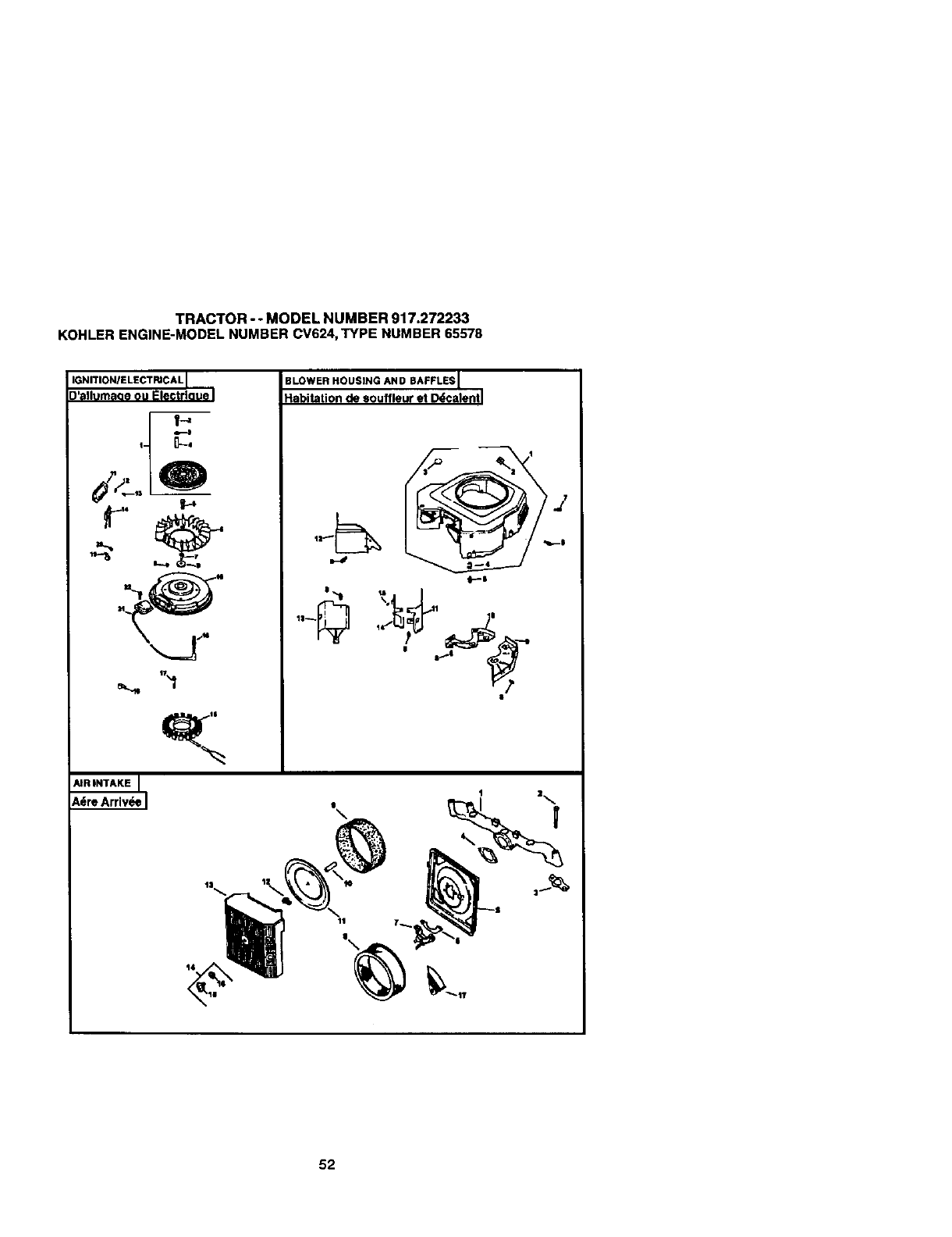
TRACTOR -- MODEL NUMBER 917.272233
KOHLERENGINE-MODELNUMBER CV624,TYPE NUMBER 65578
IGNITIONIELECTRICAL
)'allumaoe ou Electrlaue
L.
"--3
AIR INTAKE J
I
BLOWER HOUSING AND BAFFLES I
l
Habitationde souffleuret D_,calentl
_17
52
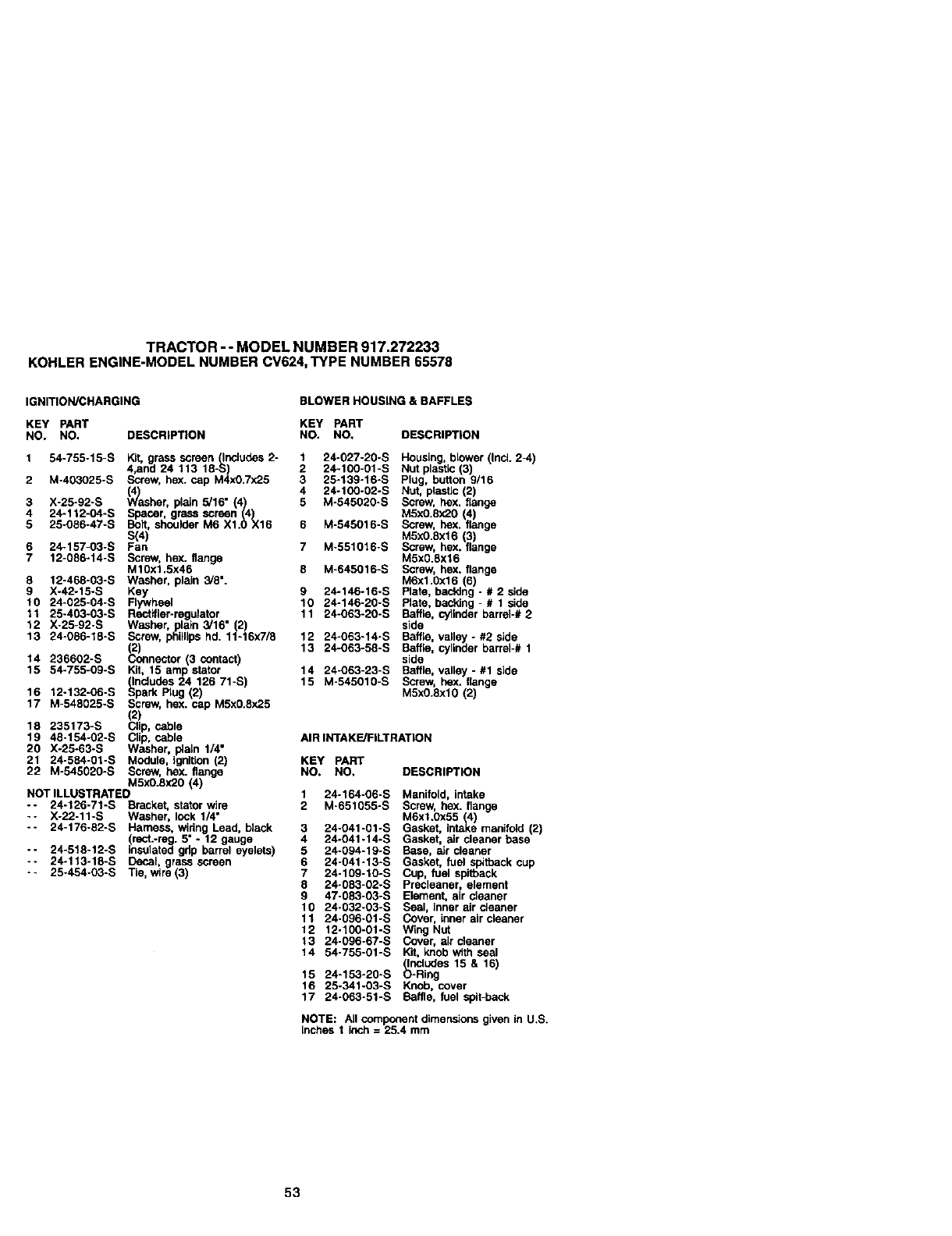
TRACTOR -- MODEL NUMBER 917.272233
KOHLERENGINE-MODELNUMBER CV624,TYPE NUMBER65578
IGNITION/CHARGING BLOWER HOUSING & BAFFLES
KEY PART KEY PART
NO. NO. DESCRIPTION NO. NO. DESCRIPTION
1 54-755-15-S Kit, grass screen (llncludes2- 1
4,and 24 113 18-S) 2
2 M-403025-S Screw, hex. cap M4xO.7x25 3
(4)(4 4
3 X-25-g2-s Washer, plain 5/16" (4) 5
4 24-112-04-S Spacer, grass screen (,4)
Bott, shoulder M6 X1.0 X15 6
5 29-056-47-S S(4)
6 24-157-03-S Fan 7
7 12-086-14-S Screw, hex. flange
M10xl.5x46 g
8 12-468-03-S Washer, plain 3/8".
9 X-42-15-S Key 9
10 24-025-04-S Flywheel 10
11 25-403-03-S Rectifier-regulator. 11
12 X-25-92-S Washer, plain 3/16 (2)
13 24-056-18-S Scrsw, phillipshd. 11-16x7/8 12
_) 13
14 236602-S onnector (3 contact)
15 54-755-09-S Kit, 15 amlpstator 14
_ndudes 24 126 71-S) 15
16 12-132-06-S _park Rug (2)
17 M-548025-S Screw, hex. cap M5x0.Sx25
(2)
18 235173-S Clip, cable
19 48-154-02-S Clip, cable
20 X-25-63-S Washer, i_aln 1/4"
21 24-584-01-S Module, Ignition (2)
22 M-545020-S Screw, hex. flange
M5xO.Sx20(4)
NOT ILLUSTRATED 1
-- 24-126-71-S Bracket, stator wire 2
-- X-22-11-S Washer, lock 1/4"
-- 24-176-82-S Harness, widng Lead, black 3
(rect.-reg. 5" -12 gauge 4
- - 24-518-12-S insulated gdp barrel eyelets) 5
-- 24-113-18-S Decal, grass screen 6
25-454-03-S Tie, wire(3) 7
8
9
10
11
12
13
14
24-027-20-S Housing,blower (Incl. 2-4)
24-100-01-B Nut plastic(3)
25-139-16-S Plug, button 9/16
24-100-02-S Nut, plastic(2)
M-545020-S Screw, hex. flange
M5x0.8x2O (4
M-545016-S Screw, hex. flange
M5xO.Sx16 (3)
M-551016-S Screw, hex. flange
M5x0.8x16
M-645016-S Screw, hex. flange
M6x1.0x16 5)
24-146-16-S Pate, backing- # 2 side
24-146-20-S Plate, bacldng- # 1side
24-063-20-S Baffle, cylinder barrel-# 2
side
24-063-14-S Baffle, valley - #2 side
24-063-58-S Baffle, cylinder barrel-# 1
side
24-063-23-S Baffle, valley - #1 side
M-545010-S Screw, hex. flange
M5x0.SxlO (2)
AIR INTAKE/FILTRATION
KEY PART
NO. NO. DESCRIPTION
24-164-06-S
M-651055-S
24-041 -Ol-S
24-041-14-S
24-094-19-S
24-041-13-S
24-109-10-S
24-083-02-S
47-083-03-S
24-032-03-S
24-096-01-S
12-100-01-S
24-096-67-S
54-755-01 -S
15 24-153-20-S
16 25-341-03-S
17 24-063-51-S
Manifold, intake
Screw, hex. flange
M6x1.0x55 (4)
Gasket, intake manifold (2)
Gasket, elr cleaner base
Base, elr cleaner
Gasket, fuel spitbackcup
Cup, fuel spig:)ack
Precleaner, element
Element, air cleaner
Seal, inner air cleaner
Cover, innerair cleaner
Wing Nut
Cover, air cieaner
Kit, knob with seal
Includes
_Ring 15 & 16)
Knob, cover
Baffle, fuel spit-back
NOTE: All component dimensions given in U.S.
inches I inch = 25.4 mm
53
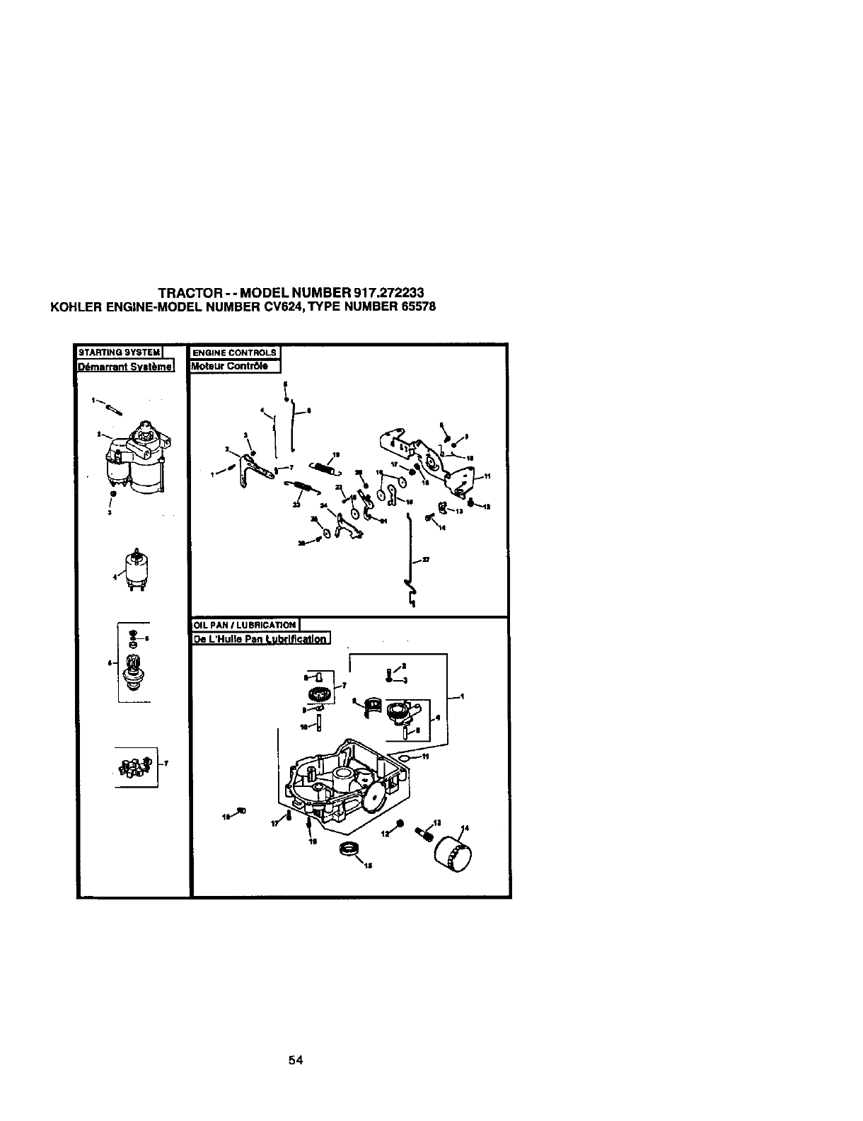
TRACTOR -- MODEL NUMBER 917.272233
KOHLERENGINE-MODELNUMBER CV624,TYPE NUMBER 65578
STARTING SYSTEM I
Ddmarrant Svstbmel
• I
/
3
ENGINE CONTROLS
Moteur Contr01e
:)ILPAN ILUBRICATION [
:)e L'Hulle Pan Lubrlficatlon I
_B
qt
t5 /11 4
54
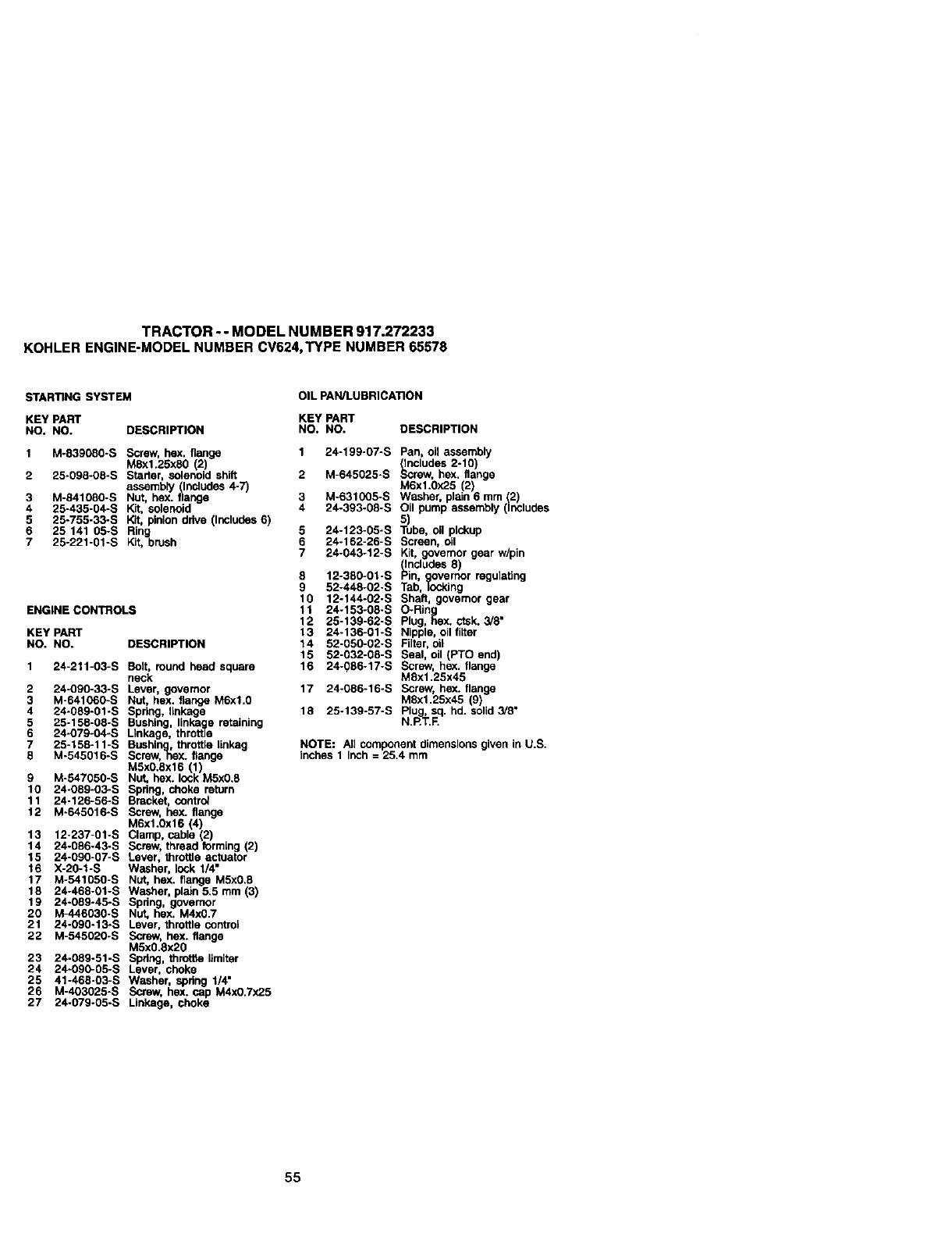
TRACTOR -- MODEL NUMBER 917.272233
KOHLERENGINE-MODELNUMBER CV624,TYPE NUMBER 65578
STARING SYSTEM OIL pAN/LUBRICATION
KEYPART KEYPART
NO. NO. DESCRIPTION NO. NO. DESCRIPTION
1 M-839080-S Screw, hex. flange
MEx1.25xE0 (2)
2 25-09B-08-S Starter, solenoid sh_ 2
assembly (Includes 4-7)
3 M-841080-S Nut hex. flange 3
4 25-435-04-S Kit. selene d 4
5 25-755-33-S Kit, pinion drive (Includes 6)
6 25 141 05-S Ring 5
7 25-221-01-S Kit, brush 6
7
ENGINE CONTROLS
KEY PART
NO. NO. DESCRIPTION
1 24-211-03-S Boit, round head square
neck
2 24-090-33-S Lever, govemor
3 M-641060-S Nut, hex. flange M6xl.0
4 24-089-01-S Spring linkage
5 25-158-08-S Bushing, linke_gee retaining
6 24-O79-04-S Linkage, throttle
7 25-158-11-S Bushing, throffie linkag
8 M-545016-S Screw, hex. flange
M5x0.Ex16 (1)
9 M-547050-S Nut, hex. lock M5x0.8
10 24-08g-03-S Spring, choke retarn
11 24-126-56-S Bracket, contr_
12 M-645016-S Screw, hex. flange
M6x1.0x16 (4)
13 12-237-01-S Clamp cable(2)
14 24-086-43-S Screw, thread form ng (2)
15 24-090-07-S Lever, throttle actuator
16 X-20-1-S Washer, lock 1/4"
17 M-541050-S Nut, hex. flange M5x0.8
18 24-468-O_-S Washer, pt_dn 5.5 mm (3)
19 24-089-45-S Spdng, governor
20 M-446030-S Nut, hex, M4x0.7
21 24-090-13-S Lever, throttle controi
22 M-545020-S Screw, hex. flange
M5x0.8x20
23 24-089-51-S Spring, throthe flmitar
24 24-090-05-S Lever, choke
25 41-46E-03-S Washer, spring 1/4"
26 M-403025*S Screw, hex. cap M4x0.7x25
27 24-079-05-S Linkage, choke
1 24-199-07-S
8
9
10
11
12
13
14
15
16
M-E45025-S
M-631005-S
24-393-08-S
24-123-05"S
24-162-25-S
24-043-12-S
12-380-01-S
52-448-02-S
12-144-02-S
24-153-08-S
25-139-62-S
24-136-01-S
52-050-02-S
52-032-08-S
24-086-17-S
17 24-086-16-S
18 25-139-57-S
Pan, oil assembly
,_CewlUdeS2-10)
•hex. flange
M6x1.0x25 (2)
Washer, plain 6 mm (2)
Oil pump assembly(Includes
)ube,0;I pickup
Screen, ell
Kit, governor gear w/pin
(includes 8)
Pin, overnor regulaflng
Tab,_lng
Shaft, govemor gear
O-Ring
Plug, hex. ctsk.3/8"
Nlppta, oil filter
Filter.oi;
Seal, oil (PTO end)
Screw. hex. flange
M8x1.25x45
Screw, hex. ,ange
M8xl.25x45 9)
N._g._..£Plu,sq. hd. solid3/8"
NOTE: All component dimensionsgiven in U.S.
inches 1 Inch =25.4 mm
55
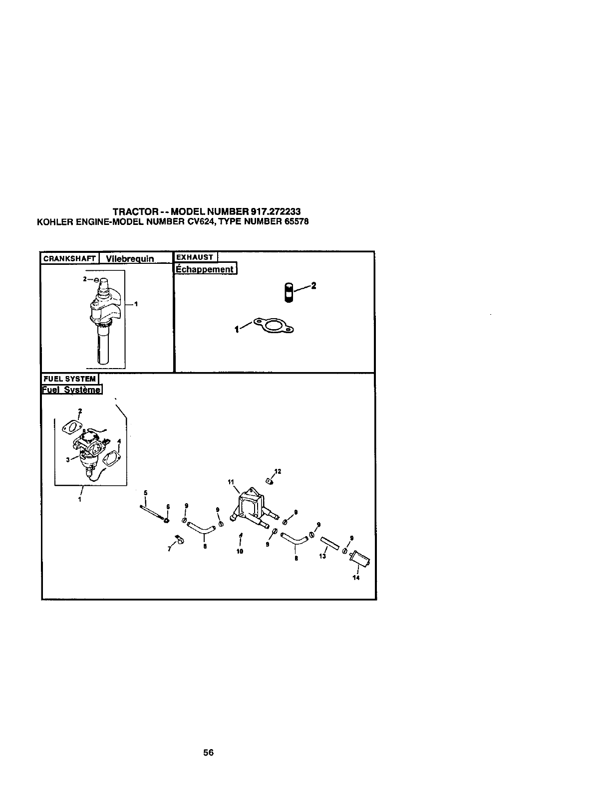
TRACTOR -- MODEL NUMBER 917.272233
KOHLERENGINE-MODELNUMBER CV624,TYPE NUMBER 65578
CRANKSHAFT I Vilebrequin
2--_ --1
EXHAUST
I_chaDDement
FUEL SYSTEM I
Fuel Svst_mel
4) ,
/
15
I o
9
t3
14
56
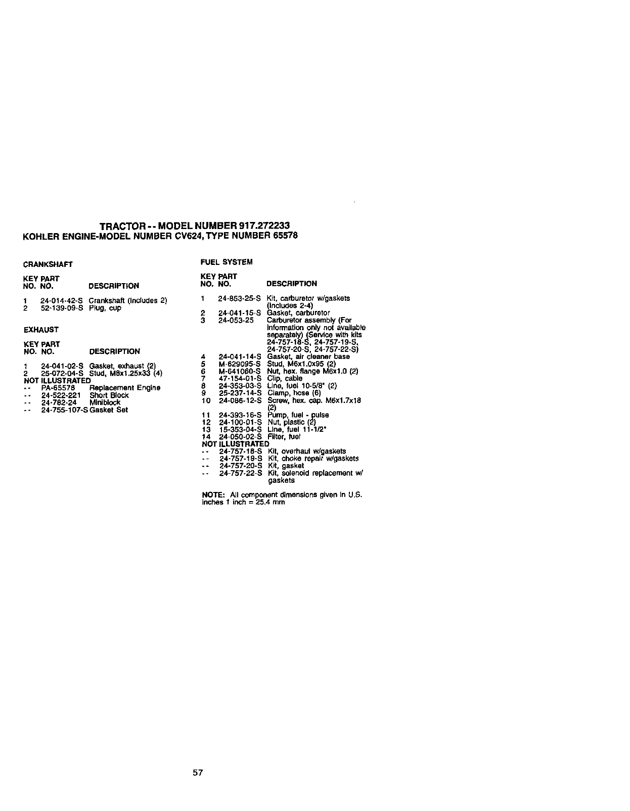
TRACTOR-- MODELNUMBER917.272233
KOHLERENGINE-MODELNUMBERCV624,TYPENUMBER65578
CRANKSHAFT
KEY PART
NO, NO. DESCRIPTION
1 24-014-42-S Crankshaft (Includes 2)
2 52-139-09-S P_ug, cup
EXHAUST
KEY PART
NO. NO. DESCRIPTION
1 24-041-02-S Gasket exhaust (2)
2 25-072-04-S Stud, M8x1.25x33 (4
NOT ILLUSTRATED
-- PA-65578 Replacement Engine
-- 24-522-221 Short Block
- - 24-782-24 MJniblock
-- 24-755-107-S Gasket Set
FUEL SYSTEM
KEY PART
NO. NO. DESCRIPTION
1 24-853-25-S Kit, carburetorw/gaskets
(Includes 2-4)
2 24-041-15-S Gasket, carburetor
3 24-053-25 Carburetorassembly (For
informationonJynot availabre
separatsly)(Service with kits
24-757-18-S 24-757-19-S,
24-757-20-S, 24-757-22-S
4 24-041-14-S Gasket, air cleaner base
5 M-629095-S Stud, M6xl.0x95 (2)
6 M-641060-S Nut, hex. flange M6xl.0 (2}
747-154-01-S Clip, cable
E 24-383-03-S Line, fuel 10-5/8" (2)
9 25-237-14-S Clamp, hose (6)
10 24-086-12-S Screw, hex, cap. M6x1.7x18
(2)
11 24-393-16-S Pump, fuel -pulse
12 24-100-01-S Nut, plastic (2)
13 15-353-04-S Line, fuel 11-1/2"
14 24-050-02-S Filter, fuel
NOT ILLUSTRATED
•- 24-757-18-S Kit, overhaul w/gaskets
-- 24-757-19-S Kit, choke repair w/gaskets
-* 24-757-20-S Kit, gasket
- - 24-757-22-S Kit, solenoid replacementw/
gaskets
NOTE: All component dimensionsgiven in U.S.
inchesI inch = 25.4 mm
57

58
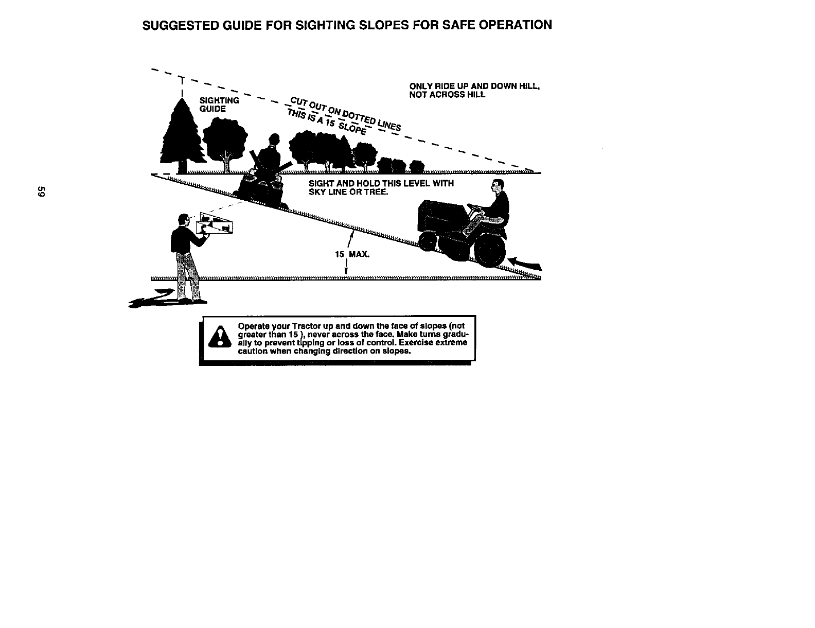
SUGGESTED GUIDE FOR SIGHTING SLOPES FOR SAFE OPERATION
O1
(D
ONLY RIDE UP AND DOWN HILL,
NOT ACROSS HILL
I_ Operate your Tractor up and down the face of slopes (not I
i
greater than 15 ), never across the face. Make turns gredu- r
ally to prevent tipping or loss of control. Exercise extreme
caution when changing direction on slopes.
For repairof Carry-_productslike vacuums,lawnequipment,and
electronics,callfor thenearestSeam Parts and RepairCenter.
1-800-488-1222 Any'_e,daycxrkjht(U.S.A.ody)
Www.,11GarlkCom
Forthe replacementparts, accessoriesandowner'smanuals
_t youneedtodo-it-yourself,calfSears PartsDIrectSM!
1-800-366-PART 6a,m,-11 p.m.. 7days awsek
(1-8_0-366-7278) (U_SA _ly)
*ww_
To purchaseor inquireabouta SearsServiceAgreement
or SearsMaintenanceAgreement:
1-600-627-6655 (u.sA) 1-600-361-6665 (C_ada)
7a.m.-5 p.m.,CST,Mon.- Sat. 9 a.n_ - 8pJ_ EST, M- F, 4 p.rn.Sal.
w.,,,,,,,,.,
Para pedrsewiciode re_ a
dom;cib,yparaordenarpiezas:
1-888_U-HOGARsu
(l-_e-_
AuCanadapourse_iceenfran_
1-800..LE.FO_ER_c
_t_VW._e4S.GEt
©_ I:_ebuckandCo.
®Registered Trademark ITMTrademark I=a Sennce Mark of Sears, Roebuc_ and Co.
®Mama RegLstrada InAMarca de F_d_ricaIs,_Mama de _de Sears, Roebuck and Co.
MCMarque de commerce IMOMan:lued_pos_e de Sears, Roebuck and Co.
179435 5.2.01 TR Printed in U.S.A.
