Craftsman 917 29331 Owners Manual ManualsLib Makes It Easy To Find Manuals Online!
2014-12-12
: Craftsman Craftsman-917-29331-Owners-Manual-119529 craftsman-917-29331-owners-manual-119529 craftsman pdf
Open the PDF directly: View PDF ![]() .
.
Page Count: 36
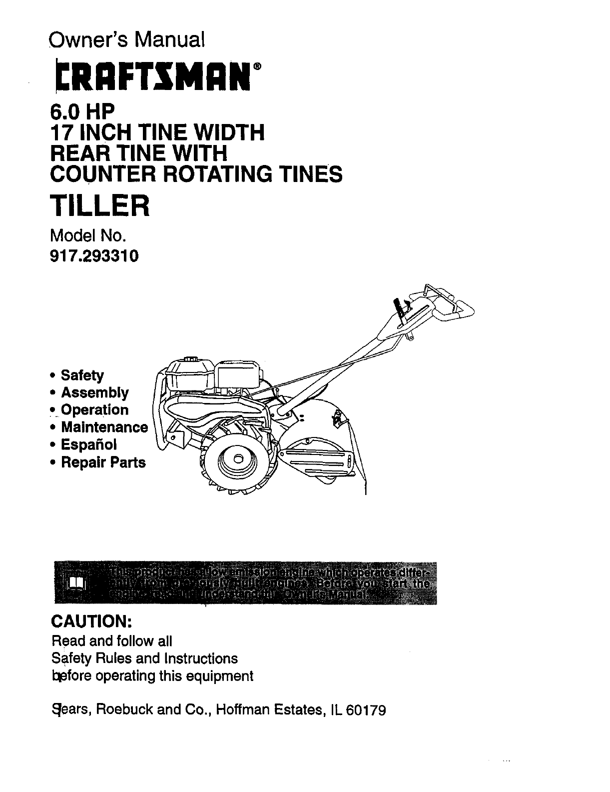
Owner's Manual
[RAFTSMAN+
6.0 HP
17 INCH TINE WIDTH
REAR TINE WITH
COUNTER ROTATING TINES
TILLER
Model No
917.293310
• Safety _
• Assembly /_
• Operation I(_._
'"°n enonce/
•Espanol _
• Repair Parts
CAUTION:
Read and followall
Safety Rulesand Instructions
101eforeoperatingthis equipment
_ears, Roebuck and Co., Hoffman Estates, IL 60179
,2
i.._: .................................... 2
.,....._...,.............,4
................................... 5
8
Service and Adjustments ...................... 1
Storage ................................................. 1
Troubleshooting .................................... 2
!llustratad Parts List .............................. 4
Parts Ordering ....................... Back Cov_
JCRAFTSMAI_ TILLER
purchase, when this Craftsman Tiller is maintained, lubr
tuned up according to the operating and maintenance instructions in the
Sears will repair free of charge any defect in material or workmanshiF
rdoes not cover:
items which become worn during normal use, such as tines, spark plug.,
belts.
because of operator abuse or negligence, including bent crank-
to maintain the equipment according to the instructions con-
tained in the owner's manual.
•If this Craftsman Tiller is used for commercial or rental purposes, this Warranty
applies for only thirty (30) days from the date of pumhase.
Warranty service is available by returning the Craftsman power mower to the nearest
Sears service center/department in the United States. This warranty applies only while
this product is in use in the United States.
This Warranty gives you specific legal rights, and you may also have other rights which
vary from state to state.
SEARS, ROEBUCKAND CO., D/817WA, HOFFMAN ESTATES, IL 60179
TRAINING
•Read the Owner's Manual carefully. Be
thoroughly familiar with the controls and
the proper use of the equipment. Know
how to stop the unit and disengage the
controls quickly.
• Never allow children to operate the
-equipment. Never allow adults to oper-
ate the equipment without proper
instruction.
•Keep the area of operation clear of all
persons, particularly small children, and
pets.
PREPARATION
•Thoroughly inspect the area where the
equipment is to be used and remove all
foreign objects.
•Disengage all clutches and shift into
neutral before starting the engine (mo-
tor).
•Do not operate the equipment without
wearing adequate outer garments. Wea,
footwear that will improve footing on
slippery surfaces.
•Handle fuel with care; it is highly flam-
mable.
•Use an approved fuel container.
• Never add fuel to a running engine or
hot engine.
•Fillfuel tank outdoorswith extreme care
Never fillfuel tank indoors.
•Replace gasoline cap securely and
clean up spilledfuel before restarting.
•Use extensioncords and receptacles as
specified by the manufacturer for all
unitswith electric drive motors or electri_
startingmotors.
•Never attempt to make any adjustments
while the engine (motor) is running
(except where specifically recommend-
ed by manufacturer).
)PERATION
Do not put hands or feet near or under
rotating parts.
Exercise extreme caution when operat-
ing on or crossing gravel drives, walks,
or roads. Stay alert for hidden hazards
or traffic. Do not carry passengers.
After striking a foreign object, stop the
engine (motor), remove the wire from
the spark plug, thoroughly inspect the
tiller for any damage, and repair the
damage before restarting and operating
the tiller.
Exercise caution to avoid slipping or
falling.
If the unit should start to vibrate abnor-
mally, stop the engine (motor) and check
immediately for the cause. Vibration is
generally a waming of trouble r
Stop the engine (motor) when leaving
the operating position.
Take all possible precautions when leav-
ing the machine unattended. D,isengage
the tines, shift into neutral, and stop the
engine.
Before cleaning, repairing, or inspecting,
shut off the engine and make certain all
moving parts have stopped. Disconnect
the spark plug wire, and keep the wire
away from the plug to prevent accidental
starting. Disconnect the cord on electric
motors.
Do not run the engine indoors; exhaust
fumes are dangerous.
Never operate the tiller without proper
guards, plates, or other safety protective
devices in place.
Keep children and pets away. :
Do not overload the machine capacity
by attempting to till too deep at too fast a
rate.
Never operate the machine at high
speeds on slippery surfaces. Look
behind and use care when backing.
Never allow bystanders near the unit.
Use only attachments and accessories
approved by the manufacturer of the
tiller.
Never operate the tiller without good vis-
ibility or light.
Be careful when tilling in hard ground.
The tines may catch in the ground and
propel the tiller forward. If this occurs,
let go of the handlebars and do not
restrain the machine.
MAINTENANCE AND STORAGE
• Keep machine, attachments, and
accessodes in safe working condition.
• Check shear pins, engine mounting
bolts, and other bolts at frequent inter-
vals for proper tightness to be sure the
equipment is in safe working condition.
•Never store the machine with fuel in the
fuel tank inside a building where ignition
sources are present, such as hot water
and space heaters, clothes dryers, and
the like. Allow the engine to cool before
storing in any enclosure.
•Always refer to the operator's guide
instructions for important details if the
tiller is to be stored for an extended
_pedod.
CAUTION: Always disconnect spark
plug wire and place wire where it cannot
contact spark plug in order to prevent acci-
dental starting when setting up, transport-
ing, adjusting or making repairs.
WARNING (
The engine exhuast from this product con-
tains chemicals known to the State of
Califomia to cause cancer, birth defectd, or
other reproductive harm.
3
PRODUCTSPECIFICATIONS
HORSEPOWER: 6.0 HP
)ISPLACEMENT: 13.53 CU. IN.
GASOLINE CAPACITY: 3Quarts
Unleaded Regular
OIL (API-SF/SG/SH): SAE 30
(Above 40°F)
CAPACITY: 19 oz.) SAE5W-30/IOW-3
(Below 40°F)
SPARK PLUG : Champion RJ19LM
GAP: .030") OR J19LM
Congratulations on your purchase of a
Craftsman Tiller. It has been designed, en-
gineered and manufactured to give you the
best possible dependability and perform-
ance.
Should you experience any problems you
cannot easily remedy, please contact your
nearest authorized Sears Service
Center/Department. We have competent,
well-trained technicians and the proper
tools to service or repair this unit.
Please read and retain this manual. The
instructions will enable you to assemble
and maintainyour tiller properly. Always
observe the SAFETY RULES".
Your new tiller has been assembled at the
factory with exception of those parts left
unassembled for shipping purposes. To
ensure safe and proper operation of your
tiller all parts and hardware you assemble
must be tightened securely. Use the cor-
reacttools as necessary to insure proper
MAINTENANCE AGREEMENT
A Sears Maintenance Agreement is avail-
able on this product. Contact your nearest
Sears storefor details.
CUSTOMER RESPONSIBILITIES
• Read and observe the safety rules.
•Follow a regular schedule in maintain-
ing, caring for and using your tiller.
•Follow the instructions under the
"Maintenance" and =Storage" sections!
this Owner's Manual.
A, WARNING: This unit is equipped wk
an internal combustion engine and shou
not be used on or near any unimproved
forest-covered, brush-covered or grass
covered land unless the engine's exhaus
system is equipped with a spark arrestet
meeting applicable local or state laws (if
any). If aspark arrester is used, it shoul
be maintained in effective working order
the operator.
In the state of California the above is
required by law (Section 4442 of the
California Public Resources Code), Oth
states may have similar laws, Federal
laws apply on federal lands. See your
Sears Authorized Service Center for spa
arrester. Refer to the Repair Parts secti_
of this manual for part number.
These accessories were available when the tiller was purchased. They are also avail-
able at most Sears Retail outlets and Service Centers, Most Sears Stores can order
[epair parts for you when you provide the model number of your tiller.
ENGINE " -
SPARK PLUG MUffLER JJR FILTER GAS CAN ' ENGINE OIL STABILIZER
TILLER PERFORMANCE
TILLER MAINTENANCE
4
Your new tiller has been assembled at the
factory with exception of those parts left
unassembled for shipping purposes. To
ensure safe and proper operation of your
tiller all pads and hardware you assemble
must be tightened securely. Use the cor-
rect tools as necessary to insure proper
tightness.
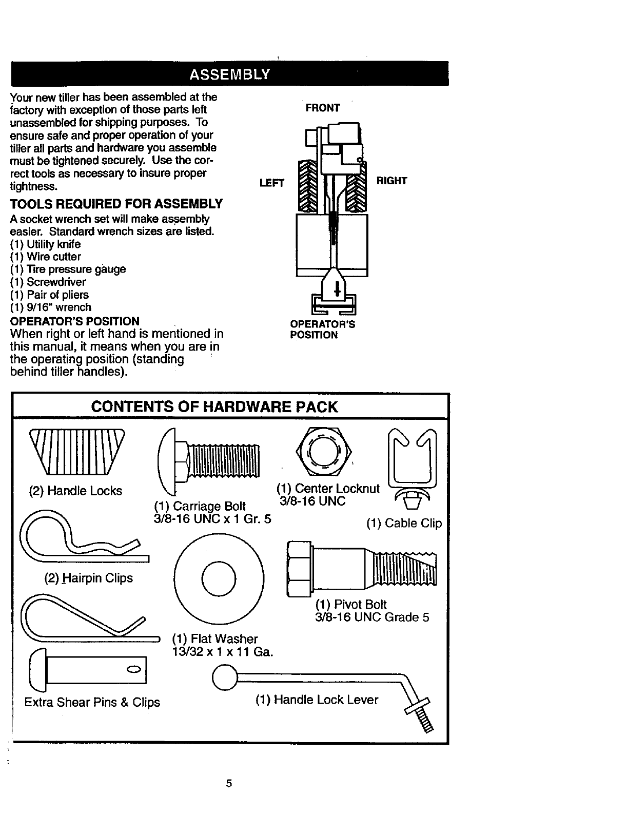
TOOLS REQUIRED FOR ASSEMBLY
A socketwrench set will make assembly
easier. Standard wrench sizes are listed.
(1) Utilityknife
(1) Wire cutter
(1) Tire pressure gauge
(1) Screwdriver
(1) Pair of pliers
(1) 9/16" wrench
OPERATOR'S POSITION
When right or left hand is mentioned in
this manual, it means when you are in
the operating position (standing '
behind tiller handles).
FRONT
LEFT
OPERATOR'S
POSITION
RIGHT
CONTENTS OF HARDWARE PACK
//IIIIII/Y
(2) Handle Locks
(1) Carriage Bolt
(1) Center Locknut
3/8-16 UNC
3/8-16 UNC x 1Gr. 5
(1) Cable Clip
(2) Hairpin Clips i _ _ ]__
(13/)8.P_NB_lt rade 5
t(1) Flat Washer
(_ . 13/32 x 1 x 11 Ga.
°I ©
Extra Shear Pins & Clips (1) Handle Lock Lever
5
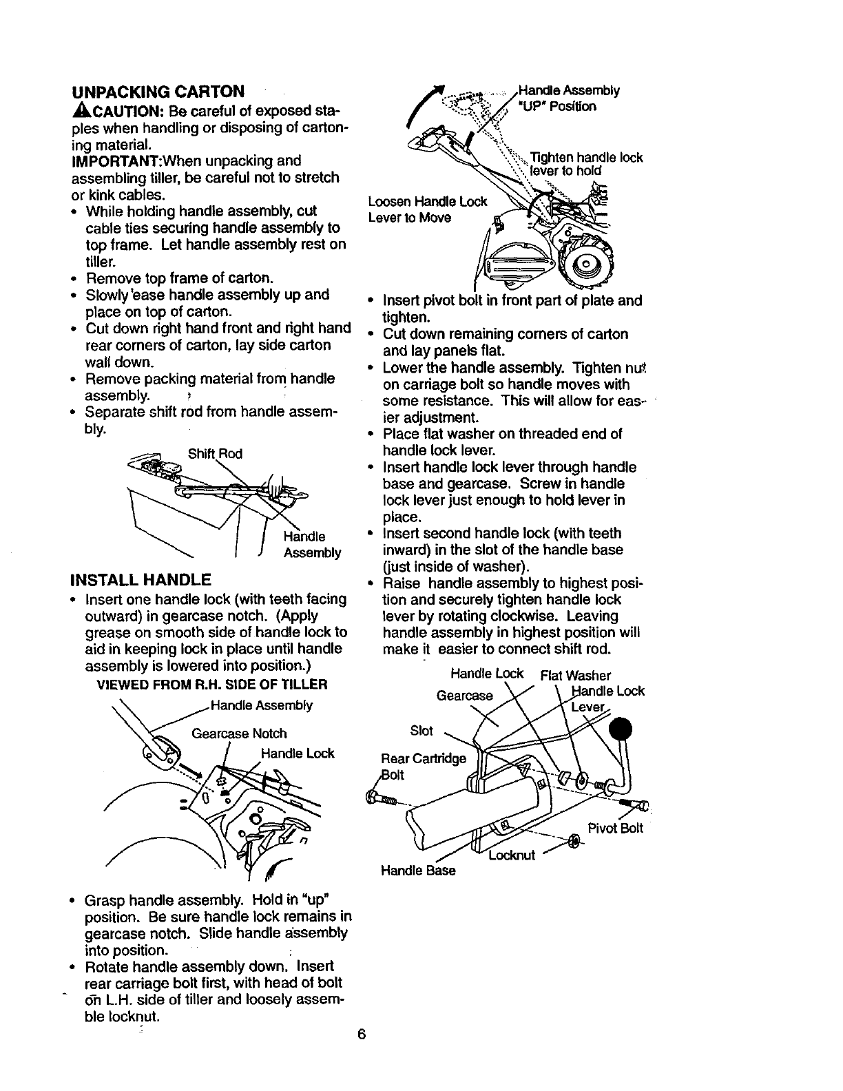
UNPACKING CARTON
_CAUTION: Be careful of exposed sta-
ples when handling or disposing of carton-
ing material.
IMPORTANT:When unpacking and
assembling tiller, be careful not to stretch
or kink cables,
•While holding handle assembly, cut
cable ties securing handle assembly to
top frame. Let handle assembly rest on
tiller.
•Remove top frame of carton.
•Slowly'ease handle assembly up and
place on top of carton.
•Cut down right hand front and right hand
rear corners of carton, lay side carton
wall down.
•Remove packing material from handle
assembly.
• Separate shift rod from handle assem-
bly.
Shift Rod
Assembly
INSTALL HANDLE
•Insert one handle lock (with teeth facing
outward) in gearcase notch. (Apply
grease on smooth side of handle lock to
aid in keeping lock in place until handle
assembly is lowered into position.)
VIEWED FROM R.H. SIDE OF TILLER
::nca_':A_:::bly
/Handle Lock
• Grasp handle assembly. Hold in "up"
position. Be sure handle lock remains in
gearcase notch. Slide handle assembly
into position.
• Rotate handle assembly down. Insert
rear carriage bolt first, with head of bolt
o-n L.H. side of tiller and loosely assem-
ble Iocknut.
6
Loosen Handle Lock
Lever to Move
•Insert pivot bolt in front part of plate and
tighten.
•Cut down remaining comers of carton
and lay panels flat.
•Lower the handle assembly. Tighten nut.
on carriage bolt so handle moves with
some resistance. This will allow for eas_
ier adjustment.
•Place flat washer on threaded end of
handle lock lever.
•Insert handle lock lever through handle
base and gearcase, Screw in handle
lock lever just enough to hold lever in
place.
• Insert second handle lock (with teeth
inward) in the slot of the handle base
(just inside of washer).
*Raise handle assembly to highest posi-
tion and securely tighten handle lock
lever by rotating clockwise. Leaving
handle assembly in highest position will
make it easier to connect shift rod.
Handle Lock Flat Washer
Gearcase
\
Slot \
Rear Cadddge
22.
Pivot Bolt
Handle Base
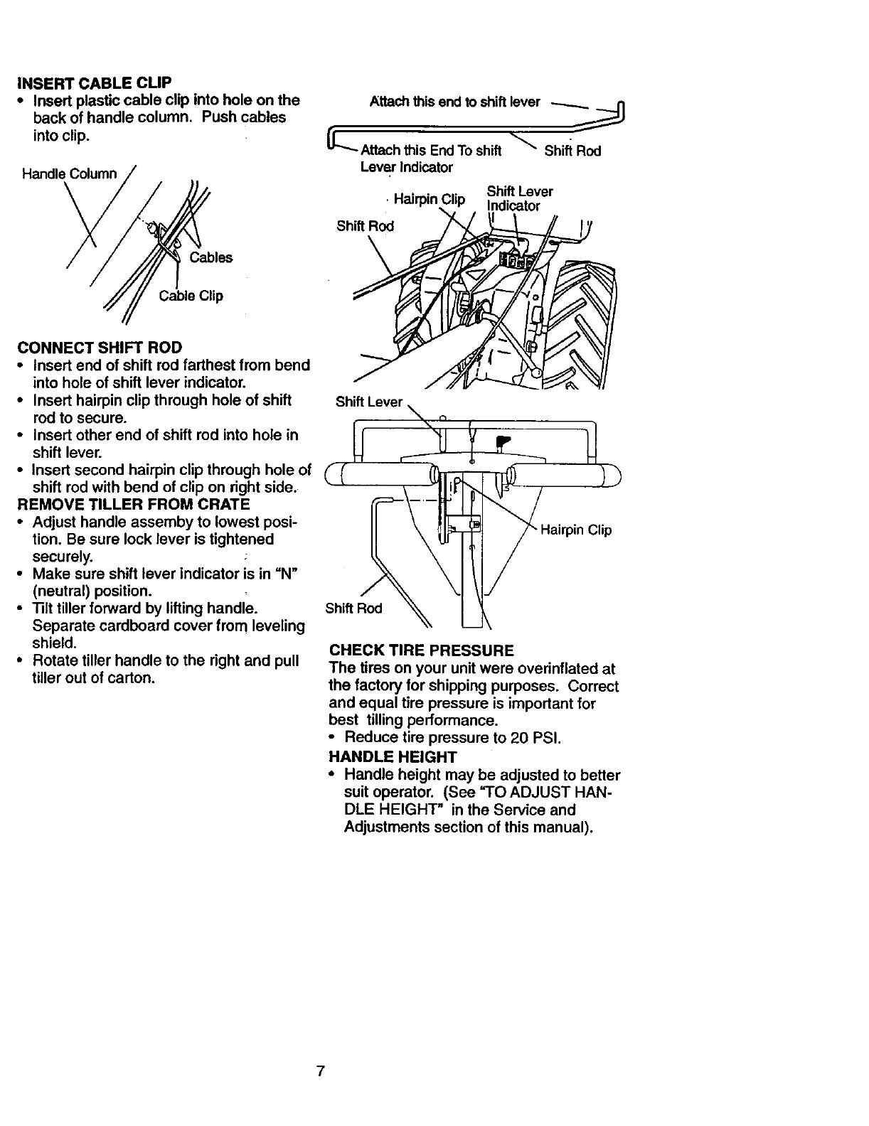
INSERT CABLE CLIP
• Insert plastic cable clip into hole on the
back of handle column. Push cables
into clip.
Handle Column
Cables
Attach this end to shiftlever -..-......_._..._
_-.-Attach this End To shift _Shift Rod
Lever Indicator
Shift Lever
• Hairpin ;lip Indicator
Shift ROd
Cable Clip
CONNECT SHIFT ROD
•Insert end of shift rod farthest from bend
into hole of shift lever indicator.
•Insert hairpin clip through hole of shift
rod to secure.
•Insert other end of shift rod into hole in
shift lever.
•Insert second hairpin clip through hole of
shift rod with bend of clip on right side.
REMOVE TILLER FROM CRATE
•Adjust handle assemby to lowest posi-
tion. Be sure lock lever is tightened
securely.
•Make sure shift lever indicator is in "N"
(neutral) position.
•Tilt tiller forward by lifting handle.
Separate cardboard cover from leveling
shield.
•Rotate tiller handle to the right and pull
tiller out of carton.
CHECK TIRE PRESSURE
The tires on your unit were overinflated at
the factory for shipping purposes. Correct
and equal tire pressure is important for
best tilling performance.
•Reduce tire pressure to 20 PSI.
HANDLE HEIGHT
•Handle height may be adjusted to better
suit operator. (See "TO ADJUST HAN-
DLE HEIGHT" in the Service and
Adjustments section of this manual).
7
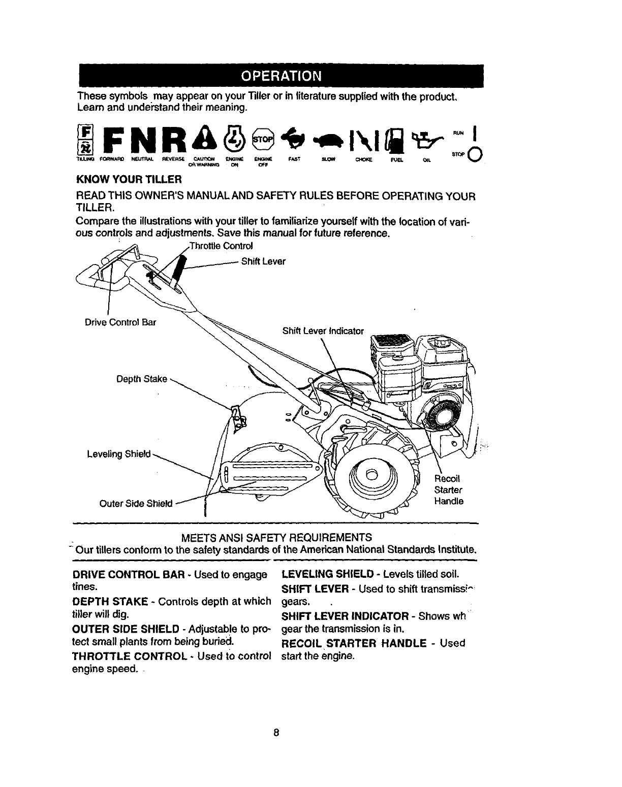
Thesesymbols mayappearonyourTillerorin literaturesuppliedwiththe product,
Learnandunder'standtheirmeaning.
FNR& o
TILI*b_ FC_NARD NE_ REVERSE P.J,t.m_l
CRWNqI_G ON OFF
KNOW YOUR TILLER
READ THIS OWNER'S MANUAL AND SAFETY RULES BEFORE OPERATING YOUR
TILLER.
Compare the illustrations with your tiller to familiarize yourself with the location of vari-
ous controls and adjustments, Save this manual for future reference.
Throttle Control
Drive Control Bar
Leveling
Outer Side Shield
Recoil
Starter
Handle
MEETS ANSI SAFETY REQUIREMENTS
_Our tillers conform to the safety standards of the Amedcan National Standards Institute,
DRIVE CONTROL BAR - Used to engage
tines.
DEPTH STAKE -Controls depth at which
tiller will dig.
OUTER SIDE SHIELD - Adjustab!e to pro-
tect small plants from being buried.
THROTTLE CONTROL - Used tO control
engine speed.
LEVEUNG SHIELD - Levels tilled soil.
SHIFT LEVER - Used to shift transmissi--
gears.
SHIFT LEVER INDICATOR - Shows wh
gear the transmission is in.
RECOIL STARTER HANDLE - Used
start the engine.
8
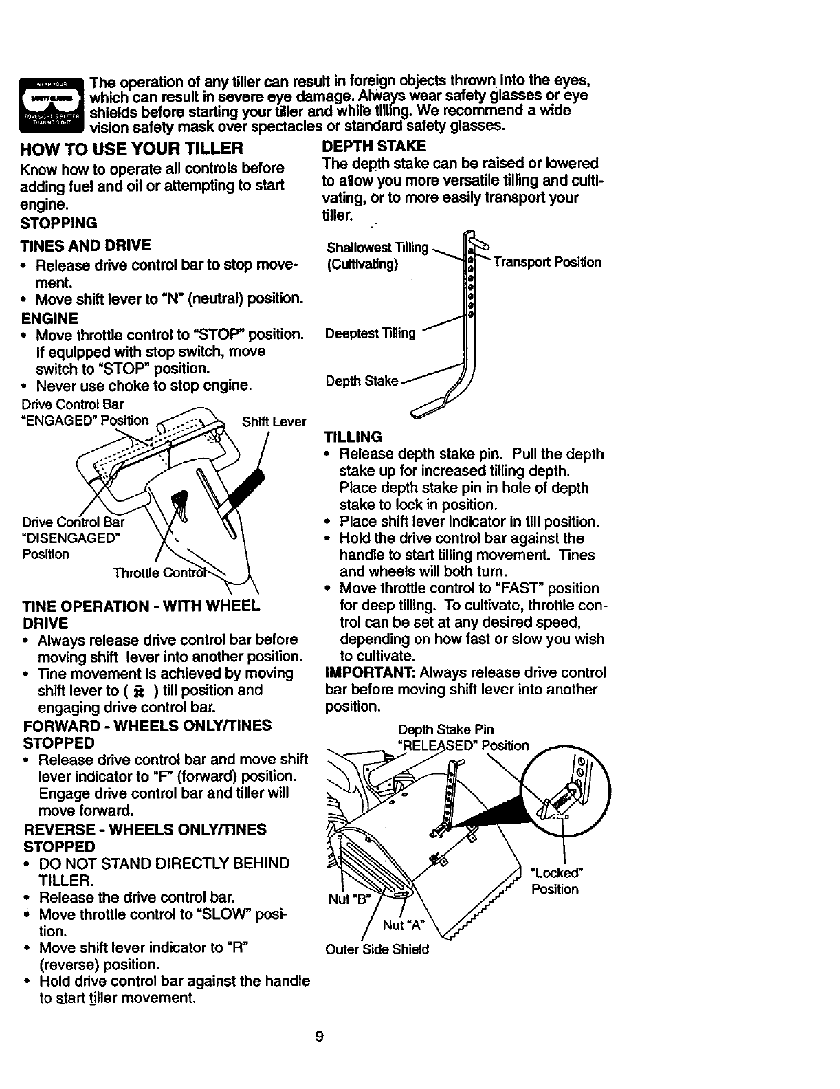
HOW TO USE YOUR TILLER
Know how to operate all controls before
adding fuel and oil or attempting to start
engine.
STOPPING
The operation of any tiller can result in foreign objects thrown into the eyes,
which can result in severe eye damage. Always wear safety glasses or eye
shields before starting your tiller and while tilling. We recommend a wide
vision safety mask over spectacles or standard safety glasses.
DEPTH STAKE
The depth stake can be raised or lowered
to allow you more versatile tilling and culti-
vating, or to more easily transport your
tiller.
TINES AND DRIVE
•Release drive control bar to stop move-
ment.
• Move shift lever to =N" (neutral) position.
ENGINE
•Move throttle control to "STOW' position.
if equipped with stop switch, move
switch to "STOP" position.
•Never use choke to stop engine.
Drive Control Bar
"ENGAGED" Position Shift Lever
Bar
=DISENGAGED"
Position
Throttle
TINE OPERATION -WITH WHEEL
DRIVE
•Always release drive control bar before
moving shift lever into another position.
•"13nemovement is achieved by moving
shift lever to ( _) till position and
engaging drive control bar.
FORWARD -WHEELS ONLY/TINES
STOPPED
•Release drive control bar and move shift
lever indicator to "F" (forward) position.
Engage drive control bar and tiller will
move forward.
REVERSE - WHEELS ONLY/TINES
STOPPED
•DO NOT STAND DIRECTLY BEHIND
TILLER.
•Release the drive control bar.
• Move throttle control to "SLOW" posi-
tion.
•Move shift lever indicator to "R"
(reverse) position.
• Hold drive control bar against the handle
to start tiller movement.
Shallowest'nlling
(Cultivating)
J
Deeptest "1311ing
Depth Stake J
"_"Transport Position
TILLING
• Release depth stake pin. Pull the depth
stake up for increased tilling depth.
Place depth stake pin in hole of depth
stake to lock in position.
•Place shift lever indicator in till position.
•Hold the drive control bar against the
handle to start tilling movement. Tines
and wheels will both turn.
•Move throttle control to "FAST" position
for deep tilling. To cultivate, throttle con-
trol can be set at any desired speed,
depending on how fast or slow you wish
to cultivate.
IMPORTANT: Always release drive control
bar before moving shift lever into another
position.
Depth Stake Pin
Nut "B"
"Locked"
Position
Outer Side Shield
9
TURNING
•Release the drive control bar.
•IViove throttle control to "SLOW" posi-
tion.
•Place shift lever indicator in =P (forward)
position. Tines will not turn.
•Lift handle to raise tines out of ground.
•Swing the handle in the opposite direc-
tion you wish to turn, being careful to
keep feet and legs away from tines.
•When you have completed your turn-
around, release the ddve control bar and
lower handle. Place shift lever in till
position and move throttle control to de-
sired speed. To begin tilling, hold ddve
control bar against the handle.
OUTER SIDE SHIELDS
The back edges of the outer side shields
are slotted so that the shields can be
raised for deep tilling and lowered for shal-
low tilling to protect small plants from
being buried. Loosen nut =A" in slot and
nut "B". Move shield to desired position
(both sides). Retighten nuts.
TO TRANSPORT
_.CAUTION: Before lifting or transport-
ing, allow tiller engine and muffler to cool.
Disconnect spark plug wire. Drain gaso-
line from fuel tank.
AROUND THE YARD
•Release the depth stake pin. Move the
depth stake down to the top hole for
transporting the tiller. Place depth stake
pin in hole of depth stake to lock in posi-
tion. This prevents tines from scuffing
the ground.
•Place shift lever indicator in "P (forward)
position for transporting.
• Hold the drive control bar against the
handle to start tiller movement. Tines
_vill not turn.
• Move throttle control to desired speed.
AROUND TOWN
•Disconnect spark plug wire.
•Drain fuel tank.
• Transport in upright position to prevent
oil leakage.
BEFORE STARTING ENGINE
IMPORTANT: Be very careful not.to allow
dirt to enter the engine when checking or
adding oil or fuel. Use clean oil and fuel
and store in approved, clean, covered con-
tainers, use clean fill funnels.
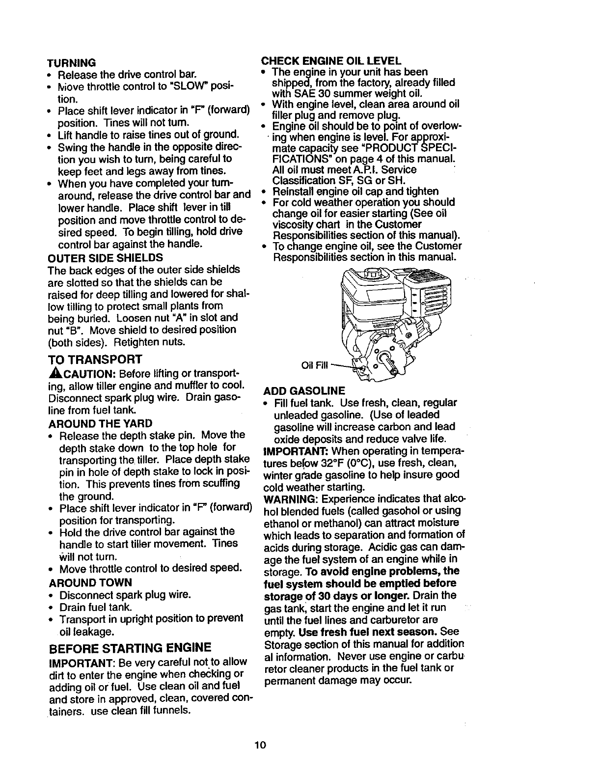
CHECK ENGINE OIL LEVEL
The engine in your unit has been
shipped, from the factory, already filled
with SAE 30 summer weight oil.
With engine level, clean area around oil
filler plug and remove plug.
•Engine oil should be to point of overlow-
• ing when engine is level. For approxi-
mate capacity see =PRODUCT SPECI-
FICATIONS" on page 4 of this manual.
All oil must meet A.RI. Service
Classification SF, SG or SH.
•Reinstall engine oil cap and tighten
•For cold weather operation you should
change oil for easier starting (See oil
viscosity chart in the Customer
Responsibilities section of this manual).
•To change engine oil, see the Customer
Responsibilities section in this manual.
ADD GASOLINE
•Fill fuel tank. Use fresh, clean, regular
unleaded gasoline. (Use of leaded
gasoline will increase carbon and lead
oxide deposits and reduce valve life.
IMPORTANT: When operating in tempera-
tures be!ow 32°F (0°C), use fresh, clean,
winter gPade gasoline to help insure good
cold weather starting.
WARNING: Experience indicates that alco-
hol blended fuels (called gasohol or using
ethanol or methanol) can attract moisture
which leads to separation and formation of
acids during storage. Acidic gas can dam-
age the fuel system of an engine while in
storage. To avoid engine problems, the
fuel system should be emptied before
storage of 30 days or longer. Drain the
gas tank, start the engine and let it run
until the fuel lines and carburetor are
empty. Use fresh fuel next season. See
Storage section of this manual for addition
al information. Never use engine or carbu
retor cleaner products in the fuel tank or
permanent damage may occur.
10
_CAUTION: Fill to within 1/2 inch of top
of fuel tank to prevent spills and to allow
for fuel expansion, if gasoline is accideno
tally spilled, move machine away from
area of spill. Avoid creating any source of
ignition until gasoline vapors have disap-
peared.
Do not overfill. Wipe off any spilled oil or
fuel. Do not store, spill or use gasoline
near an open flame.
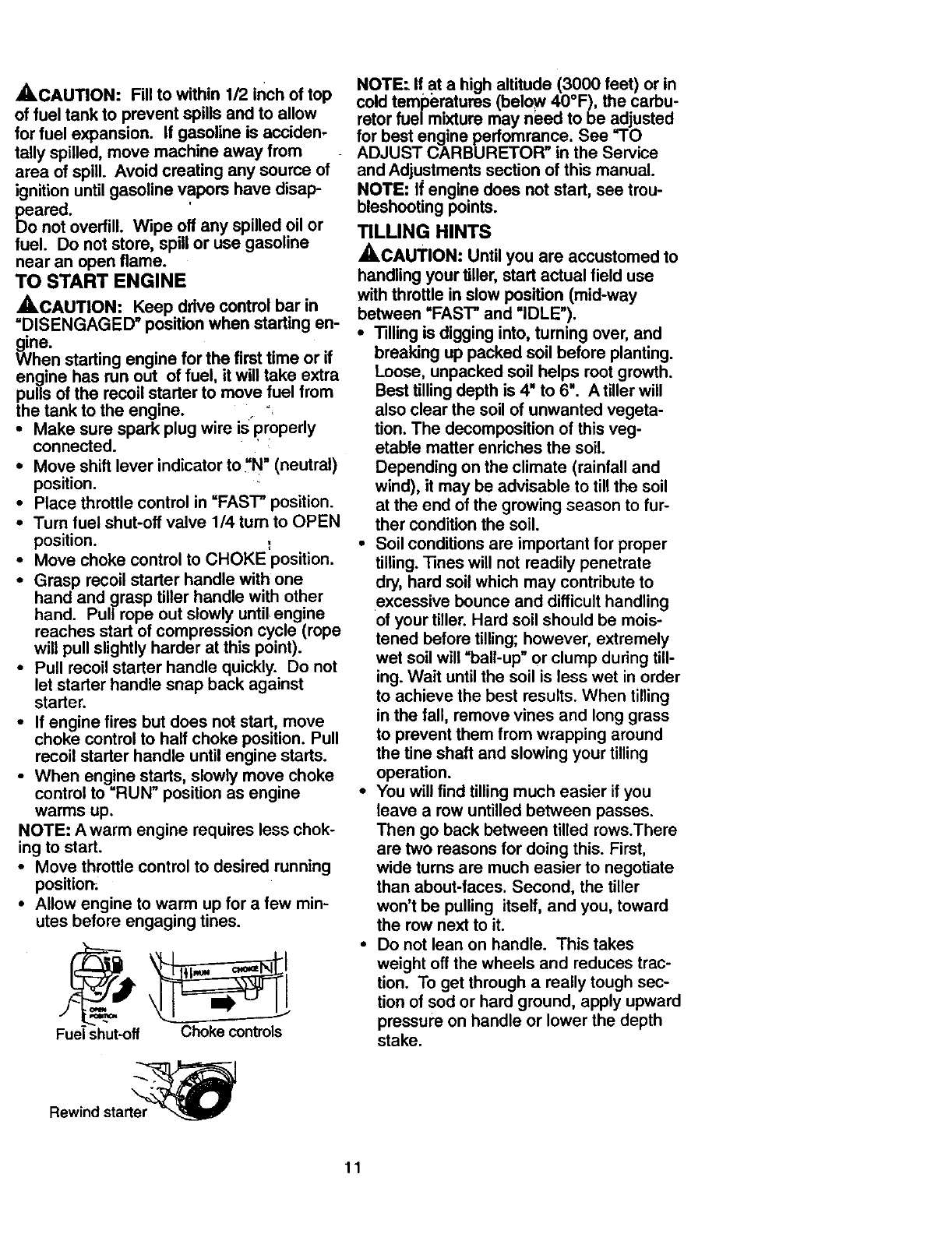
TO START ENGINE
,_.CAUTION: Keep drive control bar in
=DISENGAGED" position when starting en-
gwine.
hen starting engine for the first time or if
engine has run out of fuel, it will take extra
pulls of the recoil starter to move fuel from
the tank to the engine.
•Make sure spark plug wire is'properly
connected.
•Move shift lever indicator to_'N" (neutral)
position.
•Place throttle control in =FAST" position.
•Turn fuel shut-off valve 1/4 turn to OPEN
position. ,,
•Move choke control to CHOKE position.
•Grasp recoil starter handle with one
hand and grasp tiller handle with other
hand. Pull rope out slowly until engine
reaches start of compression cycle (rope
will pull slightly harder at this point).
•Pull recoil starter handle quickly. Do not
let starter handle snap back against
starter.
•If engine fires but does not start, move
choke control to half choke position. Pull
recoil starter handle until engine starts.
•When engine starts, slowly move choke
control to =RUN" position as engine
warms up.
NOTE: Awarm engine requires less chok-
ing to start.
•Move throttle control to desired running
positiom
•Allow engine to warm up for afew min-
utes before engaging tines.
Fuel shut-off Choke controls
Rewind start_
NOTE: If at a high altitude (3000 feet) or in
cold temperatures (below 40°F), the carbu-
retor fuel mixture may need to be adjusted
for best engine perfomrance. See "1"O
ADJUST CARBURETOR" in the Service
and Adjustments section of this manual.
NOTE: If engine does not start, see trou-
bleshooting points.
TILLING HINTS
_,CAUTION: Until you are accustomed to
handling your tiller, start actual field use
with throttle in slow position (mid-way
between =FAST" and =IDLE').
•Tilling is digging into, turning over, and
breaking up packed soil before planting.
Loose, unpacked soil helps root growth.
Best tilling depth is 4" to 6". Atiller will
also clear the soil of unwanted vegeta-
tion. The decomposition of this veg-
etable matter enriches the soil.
Depending on the climate (rainfall and
wind), it may be advisable to till the soil
at the end of the growing season to fur-
ther condition the soil.
•Soil conditions are important for proper
tilling. Tines will not readily penetrate
dry, hard soil which may contribute to
excessive bounce and difficult handling
of your tiller. Hard soil should be mois-
tened before tilling; however, extremely
wet soil will =ball-up" or clump during till-
ing. Wait until the soil is less wet in order
to achieve the best results. When tilling
in the fall, remove vines and long grass
to prevent them from wrapping around
the tine shaft and slowing your tilling
operation.
•You will find tilling much easier if you
leave a row untilled between passes.
Then go back between tilled rows.There
are two reasons for doing this. First,
wide turns are much easier to negotiate
than about-faces. Second, the tiller
won't be pulling itself, and you, toward
the row next to it.
•Do not lean on handle. This takes
weight off the wheels and reduces trac-
tion. To get through a really tough sec-
tion of sod or hard ground, apply upward
pressure on handle or lower the depth
stake.
11
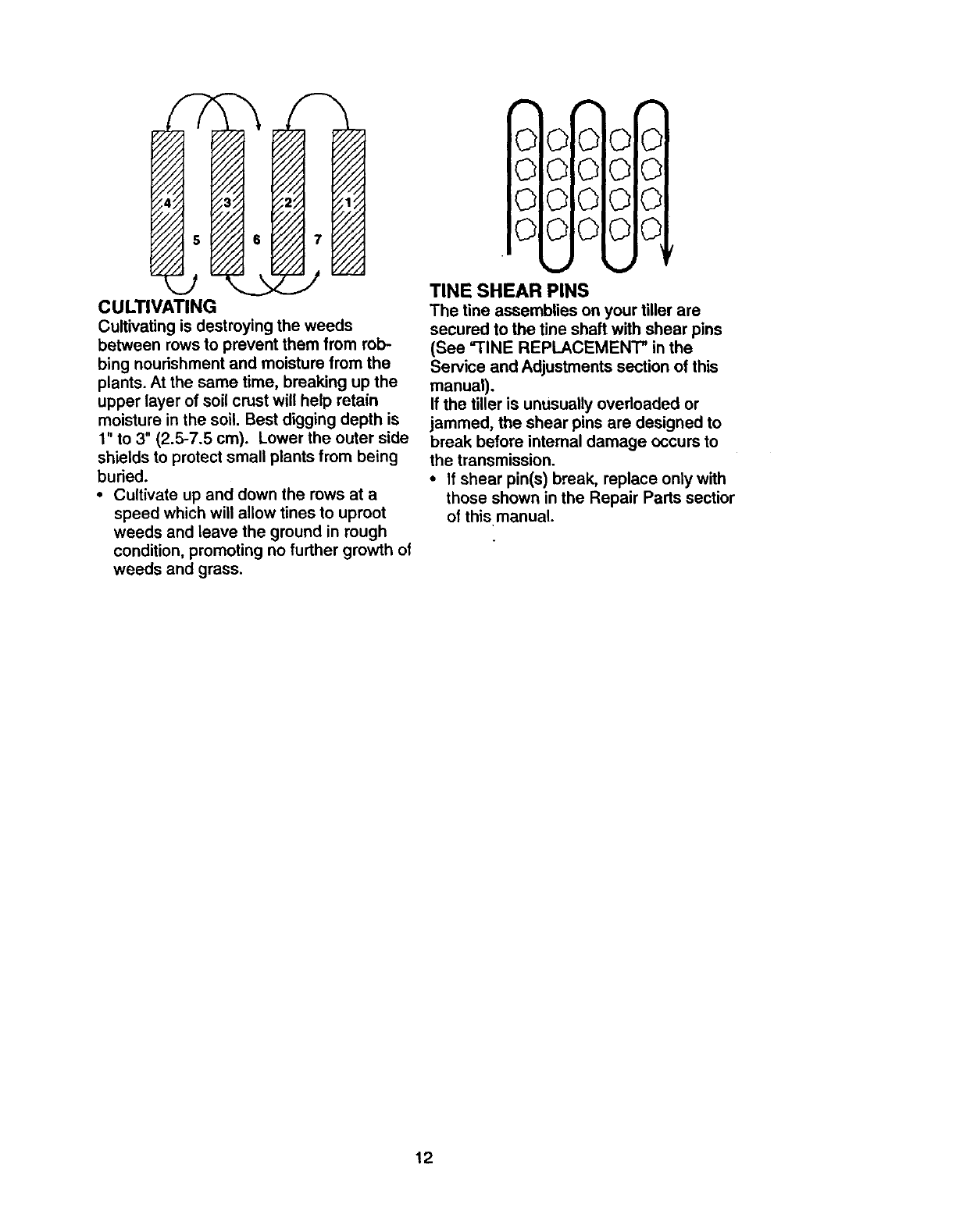
CULTIVATING
Cultivatingisdestroyingtheweeds
betweenrowsto preventthemfrom rob-
bing nourishment and moisture from the
plants. At the same time, breaking up the
upper layer of soil crust will help retain
moisture in the soil. Best digging depth is
1" to 3" (2.5-7.5 cm). Lower the outer side
shields to protect small plants from being
buried.
•Cultivate up and down the rows at a
speed which will allow tines to uproot
weeds and leave the ground in rough
condition, promoting no further growth of
weeds and grass.
I
©0,000
00!000
00[000
00lO:O 0
TINE SHEAR PINS
The tine assemblies on your tiller are
secured to the tine shaft with shear pins
(See "TINE REPLACEMENT" in the
Service and Adjustments section of this
manual).
If the tiller is unusually overloaded or
jammed, the shear pins are designed to
break before internal damage occurs to
the transmission.
•If shear pin(s) break, replace only with
those shown in the Repair Parts sectior
of this manual.
12
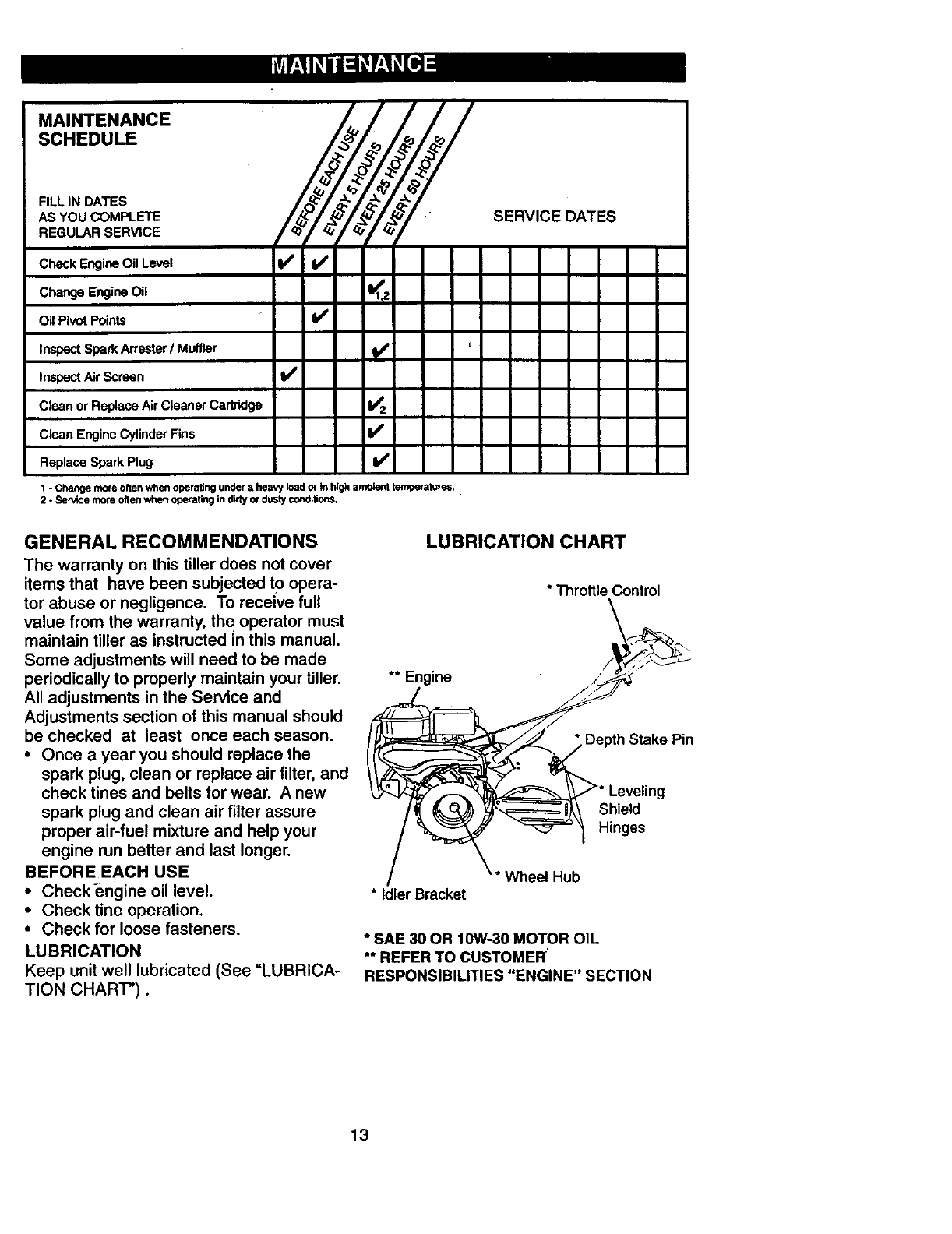
.A,.*E...CE
SCHEDULE
AS YOU COMPLETE " SERVICE DATES
REGULAR SERVICE
Check EngineOil Level Iv/
Change Engine Oil I_1,,?.
Oil pivot Points II/
Inspect Spark An'ester /Muffler I/ '
Inspect Air Screen Iv#'
Clean or Replace AirCleaner Cartridge I_ 2
Clean Engine Cylinder Fins li/
Replace Spark Plug ¥#'
1 - Change more often when operating under a heavy load or k_high ambietlt t_ture_. :
2 - Service more often when operating in dirty or dusty co_dl_s.
GENERAL RECOMMENDATIONS
The warranty on this tiller does not cover
items that have been subjected tOopera-
tor abuse or negligence. To receive full
value from the warranty, th e operator must
maintain tiller as instructed in this manual.
Some adjustments will need to be made
periodically to properly maintain your tiller.
All adjustments in the Service and
Adjustments section of this manual should
be checked at least once each season.
•Once ayear you should replace the
spark plug, clean or replace air filter, and
check tines and belts for wear. A new
spark plug and clean air filter assure
proper air-fuel mixture and help your
engine run better and last longer.
BEFORE EACH USE
• Checkengine oil level.
•Check tine operation.
•Check for loose fasteners.
LUBRICATION
Keep unit well lubricated (See "LUBRICA-
TION CHART").
LUBRICATION CHART
** Engine
* Idler Bracket
"Throttle Control
pt_h Stake Pin
_* Leveling
Shield
"_ Hinges
\ * Wheel Hub
* SAE 30 OR 10W-30 MOTOR OIL
** REFER TO CUSTOMER
RESPONSIBILITIES "ENGINE" SECTION
13
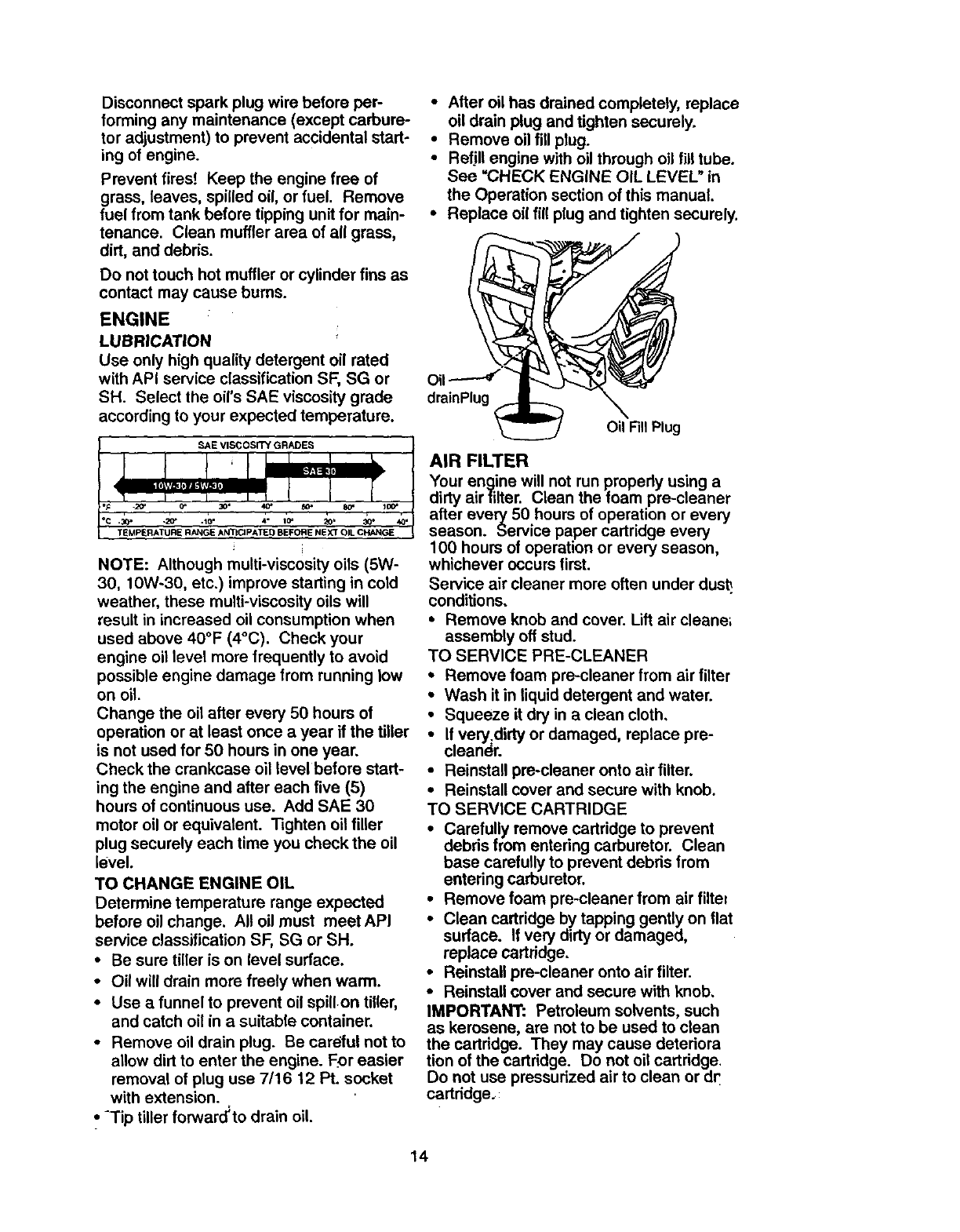
Disconnectsparkplug wire before per-
forming any maintenance (except carbure-
tor adjustment) to prevent accidental start-
ing of engine.
Prevent fires! Keep the engine free of
grass, leaves, spilled oil, or fuel. Remove
fuel from tank before tipping unit for main-
tenance. Clean muffler area of all grass,
dirt, and debris.
Do not touch hot muffler or cylinder fins as
contact may cause burns.
ENGINE
LUBRICATION
Use only high quality detergent oil rated
with API service classification SF, SG or
SH. Select the oil's SAE viscosity grade
according to your expected temperature.
SAE VISCOSITY GRADES
-L_= 0"
°C .30" .20' 20' :210"
TEMPERATURE RANGE ANTICIPATED BEFORE NEXT OIL CHANGE
NOTE: Although multi-visc0sity oils (5W-
30, 10W-30, etc.) improve starting in cold
weather, these multi-viscosity oils will
result in increased oil consumption when
used above 40°F (4°C). Check your
engine oil level more frequently to avoid
possible engine damage from running low
on oil.
Change the oil after every 50 hours of
operation or at least once a year if the tiller
is not used for 50 hours in one year.
Check the crankcase oil level before start-
ing the engine and after each five (5)
hours of continuous use. Add SAE 30
motor oil or equivalent. Tighten oil filler
plug securely each time you check the oil
level.
TO CHANGE ENGINE OIL
Determine temperature range expected
before oil change. All oil must meetAPI
service classification SF, SG or SH.
• Be sure tiller is on level surface.
• Oil will drain more freely when warm.
•Use a funnel to prevent oil spillon tiller,
and catch oil in a suitable container.
•Remove oil drain plug. Be careful not to
allow dirt to enter the engine. F_oreasier
removal of plug use 7/16 12 Pt. socket
with extension.
,, -Tip tiller forward_to drain oil.
•Alter oil has drained completely, replace
oil drain plug and tighten securely.
•Remove oil fill plug.
•Refill engine with oil through oil fill tube.
See =CHECK ENGINE OIL LEVEL" in
the Operation section of this manual.
•Replace oil fill plug and tighten securely.
Oil
drainPlug
Oil Fill Plug
AIR FILTER
Your engine will not run properly using a
dirty airfilter. Clean the foam pre-cleaner
after every 50 hours of operation or every
season. Service paper cartridge every
100 hours of operation or every season,
whichever occurs first.
Service air cleaner more often under dus_
conditions.
•Remove knob and cover. Lift air cleane;
assembly off stud.
TO SERVICE PRE-CLEANER
•Remove foam pre-cleaner from air filter
• Wash it in liquid detergent and water.
•Squeeze it dry in a clean cloth,
•If very=dirty or damaged, replace pre-
cleaner.
•Reinstall pre-cleaner onto air filter.
•Reinstall cover and secure with knob.
TO SERVICE CARTRIDGE
•Carefully remove cartridge to prevent
debris from entering carburetor. Clean
base carefully to prevent debds from
entering carburetor.
•Remove foam pre-cleaner from air filte=
•Clean cartridge by tapping gently on flat
surface. If very dirty or damaged,
replace cartridge.
•Reinstall pre-cleaner onto air filter.
•Reinstall cover and secure with knob.
IMPORTANT: Petroleum solvents, such
as kerosene, are not to be used to clean
the cartridge. They may cause deteriora
tion of the cartridge. Do not oil cartridge.
Do not use pressurized air to clean or dr
cartddge.:
14
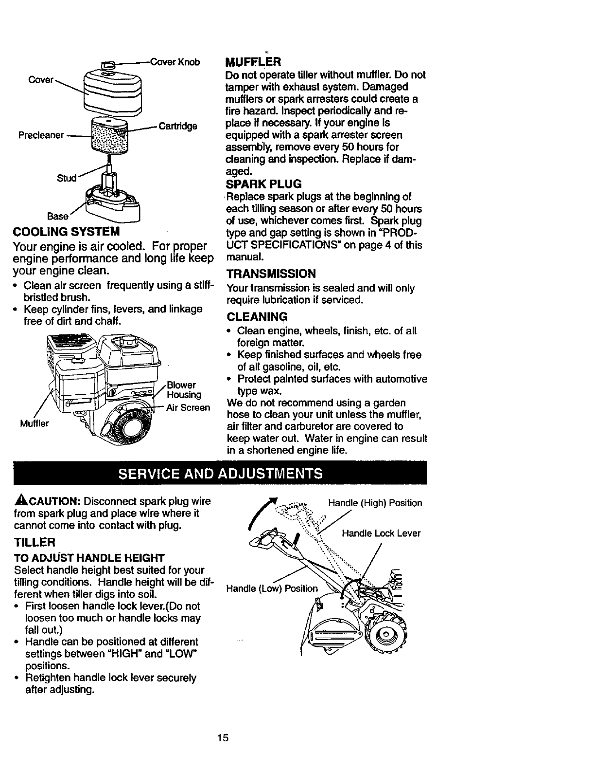
COOLING SYSTEM
Your engine is air cooled. For proper
engine performance and long life keep
your engine clean.
•Clean air screen frequently using a stiff-
bristled brush.
•Keep cylinder fins, levers, and linkage
free ofdirt and chaff.
Housing
Muffler
MUFFLE R
Do not operate tiller without muffler.Do not
tamper with exhaustsystem. Damaged
mufflersor spark an'asters could create a
fire hazard. Inspect periodicallyand re-
place if necessary. If your engine is
equipped with a spark arrester screen
assembly, remove every 50 hours for
cleaning and inspection.Replace if dam-
aged.
SPARK PLUG
Replace spark plugsat the beginningof
each tillingseason or after every 50 hours
of use, whichever comes first. Spark plug
type and gap setting is shown in =PROD-
UCT SPECIFICATIONS" on page 4 ofthis
manual.
TRANSMISSION
Your transmission is sealed and will only
require lubrication if serviced.
CLEANIN G
•Clean engine, wheels, finish, etc. of all
foreign matter.
•Keep finished surfaces and wheels free
of all gasoline, oil, etc.
•Protect painted surfaces with automotive
type wax.
We do not recommend using a garden
hose to clean your unit unless the muffler,
air filter and carburetor are covered to
keep water out. Water in engine can result
in a shortened engine life.
A, CAUTION: Disconnect spark plug wire
from spark plug and place wire where it
cannot come into contact with plug.
TILLER
TO ADJUST HANDLE HEIGHT
Select handle height best suited for your
tilling conditions. Handle height will be dif-
ferent when tiller digs into soil.
• First loosen handle lock lever.(Do not
loosen too much or handle locks may
fall out.)
•Handle can be positioned at different
settings between =HIGH" and =LOW"
positions.
•Retighten handle lock lever securely
after adjusting.
Handle (Low) Position
Handle (High) Position
Handle Lock Lever
15
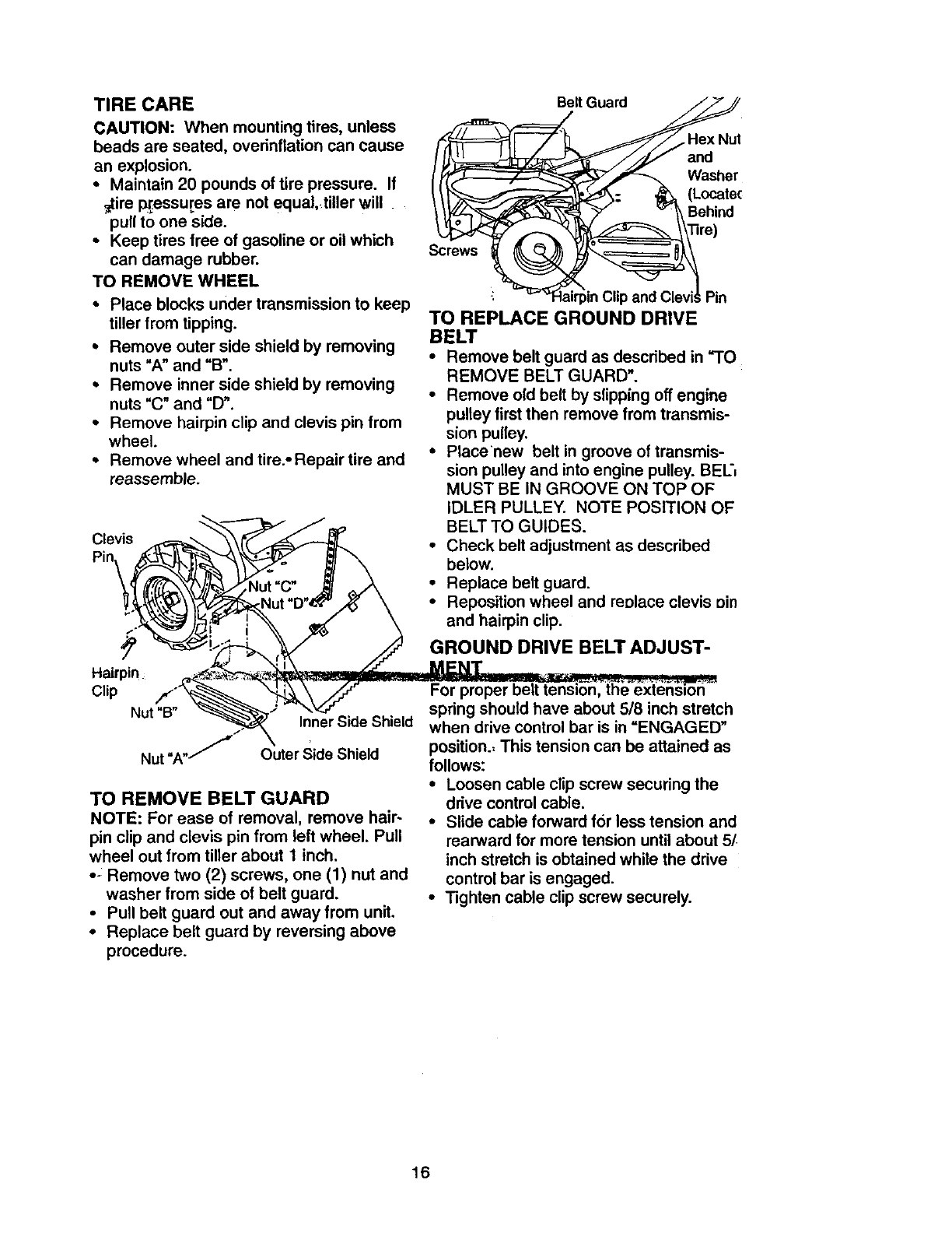
TIRE CARE
CAUTION: When mounting tires, unless
beads are seated, overinflation can cause
an explosion.
•Maintain 20 pounds of tire pressure. If
_tire w_essures are not equal, tiller will
pull to one side.
•Keep tires free of gasoline or oil which
can damage rubber.
TO REMOVE WHEEL
•Place blocks under transmission to keep
tiller from tipping.
° Remove outer side shield by removing
nuts "A" and "B".
• Remove inner side shield by removing
nuts "C" and "D".
° Remove hairpin clip and clevis pin from
wheel.
• Remove wheel and tire.-Repair tire and
reassemble.
Belt Guard
and
Washer
(Locatec
Behind
Screws
Pin
TO REPLACE GROUND DRIVE
BELT
•Remove belt guard as described in "TO
REMOVE BELT GUARD'.
•Remove old belt by slipping off engine
pulley first then remove from transmis-
sion pulley.
•Place'new belt in groove of transmis-
sion pulley and into engine pulley. BEL',
MUST BE IN GROOVE ON TOP OF
IDLER PULLEY. NOTE POSITION OF
_-_ /_,_ BELTTO GUIDES.
Clevis ----- ",\ ff _ _ •
t-m-" _._ \\[_F_ Check belt adjustment as descnbed
\ _--_._"_ _ _ below.
_[ (_%_/j/_../l_tNut "C" _/ ,_k • Replace belt guard.
_._,_'_Nut"D"_'/_' \ °Repositionwheelandreolaceclevisein
_._":_ )_j_'-Ir_ _'" " _ and hairpin clip.
f GROUNDDR,VEBE'TA U T-
. . -. M_NT ..,
CI,p _ _'_"_-// -For proper belt tensJo'_nlt_h_"_x_t_,_ ''"
Nut"B" _"_'_,= "_"_. '/_f-.. _. spring should have about 5/8 inch stretch
Inner Side Sh=eld
' " when drive control bar is in ENGAGED
_.._ ....... position- This tension can be attained as
Nut "A"/ umer _ae _nlela follows:'"
TO REMOVE BELT GUARD
NOTE: For ease of removal, remove hair-
pin clip and clevis pin from left wheel. Pull
wheel out from tiller about 1 inch.
• - Remove two (2) screws, one (1) nut and
washer from side of belt guard.
•Pull belt guard out and away from unit.
•Replace belt guard by reversing above
procedure.
•Loosen cable clip screw securing the
drive control cable.
•Slide cable forward for less tension and
rearward for more tension until about 5[
inch stretch is obtained while the drive
control bar is engaged.
•Tighten cable clip screw securely.
16
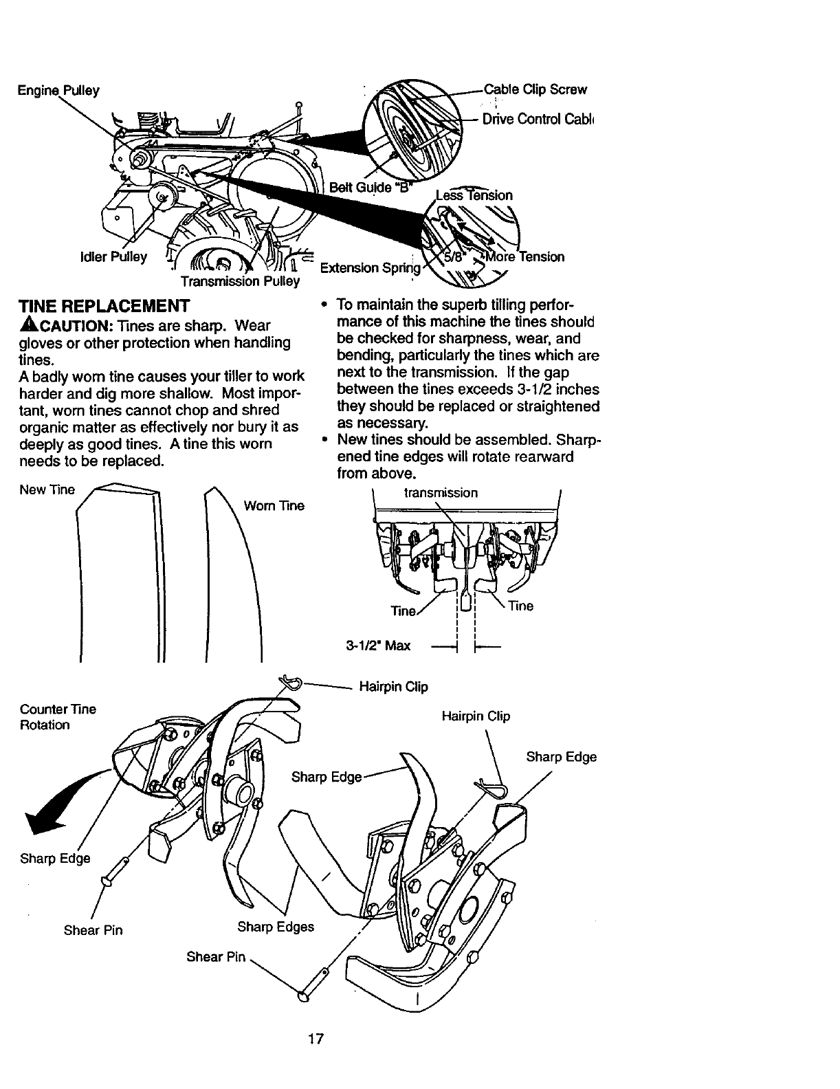
Engine_
Screw
Cabl_
Idler Pulley
Transmission Pulley
TINE REPLACEMENT
_CAUTION: Tines are sharp. Wear
gloves or other protection when handling
tines.
Abadly worn tine causes your tiller to work
harder and dig more shallow. Most impor-
tant, worn tines cannot chop and shred
organic matter as effectively nor bury it as
deeply as good tines. A tine this worn
needs to be replaced.
New "line
•To maintain the superb tilling pedor-
mance of this machine the tines should
be checked for sharpness, wear, and
bending, particularly the tines which are
next to the transmission. If the gap
between the tines exceeds 3-1/2 inches
they should be replaced or straightened
as necessary.
•New tines should be assembled. Sharp-
ened tine edges will rotate rearward
from above.
transmission
Counter "line
Rotation
Sharp Edgq
Hairpin Clip
Sharp Edge
Sharp Edge
Shear Pin Sharp Edges
17
ENGINE
Maintenance, repair, or replacement of the
emission control devices and systems,
which are being done at the customers
expense, may be performed by any non-
road engine repair establishment or indi-
vidual. Warranty repairs must be per-
formed by an authorized engine manufac-
turer's service outlet.
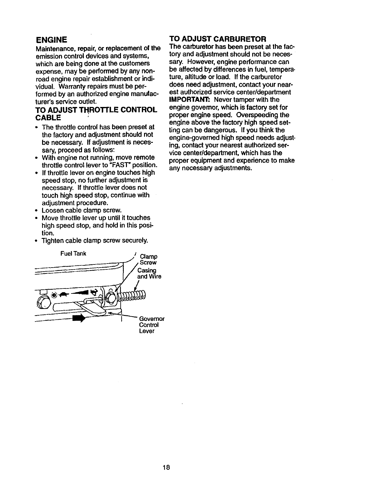
TO ADJUST THROTTLE CONTROL
CABLE
•The throttle control has been preset at
the factory and adjustment should not
be necessary. If adjustment is neces-
sary, proceed as follows:
•With engine not running, move remote
throttle control lever to "FAST" position.
•If throttle lever on engine touches high
speed stop, no further adjustment is
necessary. If throttle lever does not
touch high speed stop, continue with
adjustment procedure.
• Loosen cable clamp screw.
•Move throttle lever up until it touches
high speed stop, and hold in this posi-
tion.
•Tighten cable clamp screw securely.
Fuel Tank /Clamp
,Screw
and Wire
TO ADJUST CARBURETOR
The carburetor has been preset at the fac-
tory and adjustment should not be neces-
sary. However, engine performance can
be affected by differences in fuel, tempera.
ture, altitude or load, If the carburetor
does need adjustment, contact your near-
est authorized service center/department
IMPORTANT: Never tamper with the
engine govemor, which is factory set for
proper engine speed. Overspeeding the
engine above the factory high speed set-
ting can be dangerous. If you think the
engine-governed high speed needs adjust-
ing, contact your nearest authorized ser-
vice centerldepartment, which has the
proper equipment and experience to make
any necessary adjustments.
Control
Lever
18
Immediatelyprepareyour tillerfor storage
atthe endof theseasonor if theunitwill
notbeusedfor 30 days or morn.
_.CAUTION: Never store the tiller with
gasoline in the tank inside a building
where fumes may reach an open flame or
spark. Allow the engine to cool before
storing in any enclosure.
TILLER
• Clean entire tiller (See =CLEANING" in
the Maintenance section of this manual).
•Inspect and replace belts, if necessary
(See belt replacement instructions in the
Service and Adjustments section of this
manual). -
•Lubricate as shown in the Maintenance
section of this manual.
• Be sure that all nuts, bolts and screws
are securely fastened. Inspect moving
parts for damage, breakage and wear.
Replace if necessary.
• Touch up atl rusted or chipped paint sur-
faces; sand lightly before painting.
ENGINE
FUEL SYSTEM
IMPORTANT: It is important to prevent
gum deposits from forming in essential fuel
system parts such as the carburetor, fuel
filter, fuel hose, or tank during storage.
also, experience indicates that alcohol
blended fuels (called gasohol or using
ethanol or methanol) can attract moisture
which leads to separation and formation of
acids during storage. Acidic gas can dam-
age the fuel system of an engine while in
Storage.
•Drain the fuel tank.
•Start the engine and let it run until the
fuel lines and carburetor are empty.
•Never use engine or carburetor cleaner
products in the fuel tank or permanent
damage may occur.
• Use fresh fuel next season.
NOTE: Fuel stabilizer is an acceptable
alternative in minimizing the formation of
fuel gum depositsduring storage. Add sta-
bilizertOgasoline in fuel tank or storage
container. Always follow the mix ratio
found on stabilizer container. Run engine
at least 10 minutes after adding stabilizer
to allow the stabilizer to reach the carbure-
tor. Do notdrain the gas tank and carbu-
retor if using fuel stabilizer.
ENGINE OIL
Drain oil (with engine warm) and replace
with clean oil. (See =ENGINE" in the
Maintenance section of this manual).
CYLINDER(S)
•Remove spark plug.
•Pour 1 ounce (29 ml) of oil through
spark plug hole into cylinder,
•Pull starter handle slowly several times
to distribute oil,
•Replace with new spark plug.
OTHER
• Do not store gasoline from one season
to another.
•Replace your gasoline can if your can
starts to rust. Rust and/or dirt in your
gasoline will cause problems.
•If possible, store your unit indoors and
cover it to give protection from dust and
dirt.
•Cover your unit with a suitable protective
cover that does not retain moisture. Do
not use plastic. Plastic cannot breathe
which allows condensation to form and
will cause your unit to rust.
IMPORTANT: Never cover tiller while
engine and exhaust areas are still warm.
19
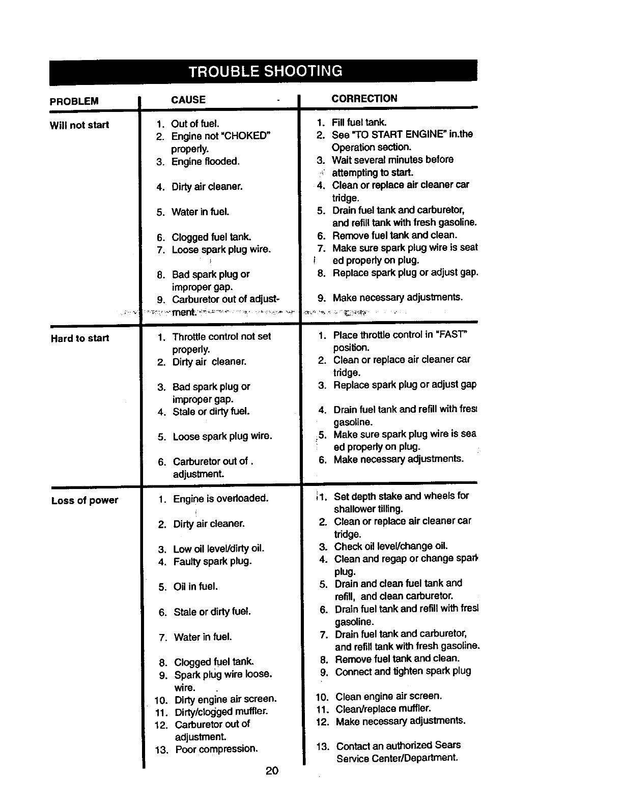
PROBLEM
Will not start
Hard to start
Loss of power
CAUSE
1. Out of fuel.
2. Engine not "CHOKED"
properly.
3. Engine flooded.
4. Dirtyair cleaner.
5. Water in fuel.
6. Clogged fuel tank.
7. Loose spark plug wire,
}
8. Bad spark plugor
impropergap.
9. Carburetor out of adjust-
1. Throttle controlnot set
properly.
2. Dirty air cleaner.
3. Bad spark plugor
impropergap.
4. Stale or dirty fuel.
5. Loose spark plugwire.
6. Carburetor out of.
adjustment.
1. Engine is overloaded.
2. Dirty air cleaner.
3. Low oil leveVdirtyoil.
4. Faulty spark plug.
5. Oi_in fuel.
6. Stale or dirtyfuel.
7. Water in fuel.
8. Clogged fuel tank.
9. Spark plug wire loose.
wire.
10. Dirty engine air screen.
11. Didy/clocjgedmuffler.
12. Carburetor out of
adjustment.
13. Poor compression.
2O
CORRECTION
1. Fill fuai tank.
2. Sea "TO START ENGINE" in.the
Operation section.
3. Wait several minutes before
:attemptingto start.
4. Clean or replace air cleaner car
tridge.
5. Drainfuel tank and carburetor,
and refilltank with fresh gasoline.
6. Remove fuel tank and clean.
7. Make sure spark plug wire is seat
ied propedyon plug.
8. Replace spark plugor adjust gap.
9. Make necessary adjustments.
1. Place throttlecontrol in "FAST"
posil_on.
2. Clean or replace air cleaner car
tridge.
3. Replace spark plug or adjust gap
4. Drain fuel tank and refillwithfrest
gasoline.
_5. Make sure spark plugwire is sea
ed properlyon plug.
6. Make necessaryadjustrnents.
;1.
2.
3.
4.
5.
6.
7.
8.
9.
10.
11.
12.
13.
Set depth stake and wheels for
shallower tilling.
Clean or replace air cleaner car
tridge.
Check oil level/change oil.
Clean and regap or change spad,
plug.
Drain and dean fuel tank and
refill, and clean carburetor.
Drain fuel tank and refillwith fresl
gasoline.
Drain fuel tank and carburetor,
and refilltank with fresh gasoline.
Remove fuel tank and clean.
Connect and tighten spark plug
Clean engine air screen.
Clean/replace muffler,
Make necessaryadjustments.
Contact an authorized Sears
Service Center/Department.
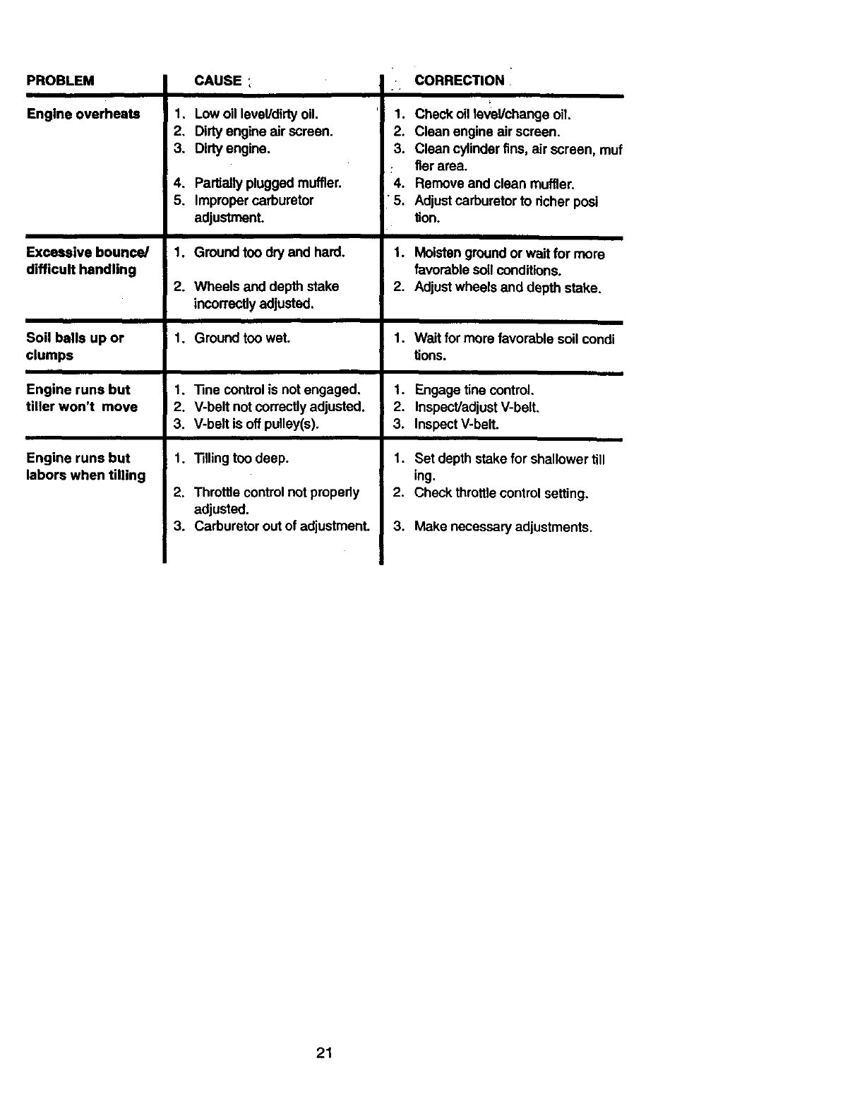
PROBLEM
Engineoverheats
Excessivebounce/
difficulthandling
Soil balls up or
clumps
Engine runs but
tiller won't move
Engine runs but
labors when tilling
CAUSE
1, Low oil level/didy oil.
2, Dirty engine air screen.
3. Dirty engine.
4. Partiallypluggedmuffler.
5. Impropercarburetor
adjustment.
1. Ground too dry and hard.
2. Wheels and depth stake
incorrectlyadjusted.
1. Ground too wet.
1.
2.
3.
1.
2.
3.
"l]necontrol is not engaged,
V-belt not correctlyadjusted.
V-belt is off pulley(s).
"13ilingtoo deep.
Throttle control notpropedy
adjusted.
Carburetor outof adjustmenL
CORREC_ON
,r
1. Check oil le_lal/changeoil.
2. Clean engine air screen.
3. Clean cylinderfins, air screen, muf
:tier area.
4. Remove and clean muffler.
•5. Adjustcarburetorto richer posi
tion.
1. Moistengroundor wait for more
favorable soil conditions.
2. Adjustwheels and depth stake.
1.
t,
2.
3.
1.
2.
3.
Wait for more favorable soil condi
tions.
Engage tine control.
Inspec_adjustV-belt.
InspectV-belt.
Set depth stake for shallower till
ing.
Check throttle controlsetting.
Make necessary adjustments.
21
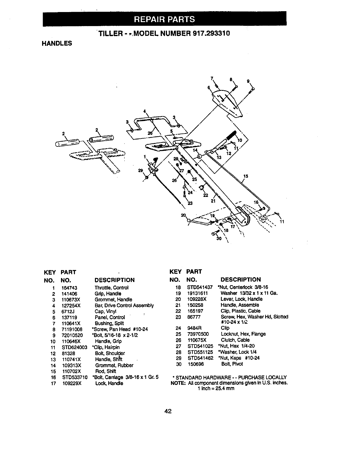
TILLER - ,,MODEL NUMBER 917.293310
HANDLES
3
2
15
\
_\\ Y\
30 \\
11
KEY PART
NO. NO. DESCRIPTION
1 164743 Throttle,Control
2 141406 Gdp, Handle
3 110673X Grommet,Handle
4 127254X Bar,DriveControl Assembly
5 6712J Cap, Vinyt
6 137119 Panel, Control
7 110641X Bushing,Split
8 71191008 *Screw, Pan Head #10-24
9 72010520 *Bolt,5/16-18 x2-1/2
10 110646X Handle, Grip
11 STD624003 •Clip, Hairpin
12 81328 Bolt, Shoulder
13 110741X Handle,SHift
14 109313x Grommet,Rubber
15 110702X Rod,Shift
16 STD533710 *Bolt,Carriage 3/8-16xl Gr. 5
17 109229X Lock,Handle
KEY
NO.
18
19
2O
21
22
23
24
25
26
27
28
29
3O
PART
NO. DESCRIPTION
STD541437 *Nut, Centedock 3/8-16
19131611 Washer 13/32 x 1 x 11Ga.
109228X Lever, Lock,Handle
150258 Handle,Assemble
165197 Clip, Plastic,Cable
86777 Screw,Hex, WasherHd, Slotted
#10-24 x 1/2
9484R Clip
73970500 Locknut,Hex, Flange
110675X Clutch, Cable
STD541025 *Nut, Hsx 1/4-20
STD551125 *Washer, Lock 1/4
STD541462 "Nut, Keps #10-24
150696 Bolt, Pivot
•STANDARD HARDWARE --PURCHASE LOCALLY
NOTE: Allcomponentdimensionsgivenin U.S. inches.
1 inch= 25.4 mm
42
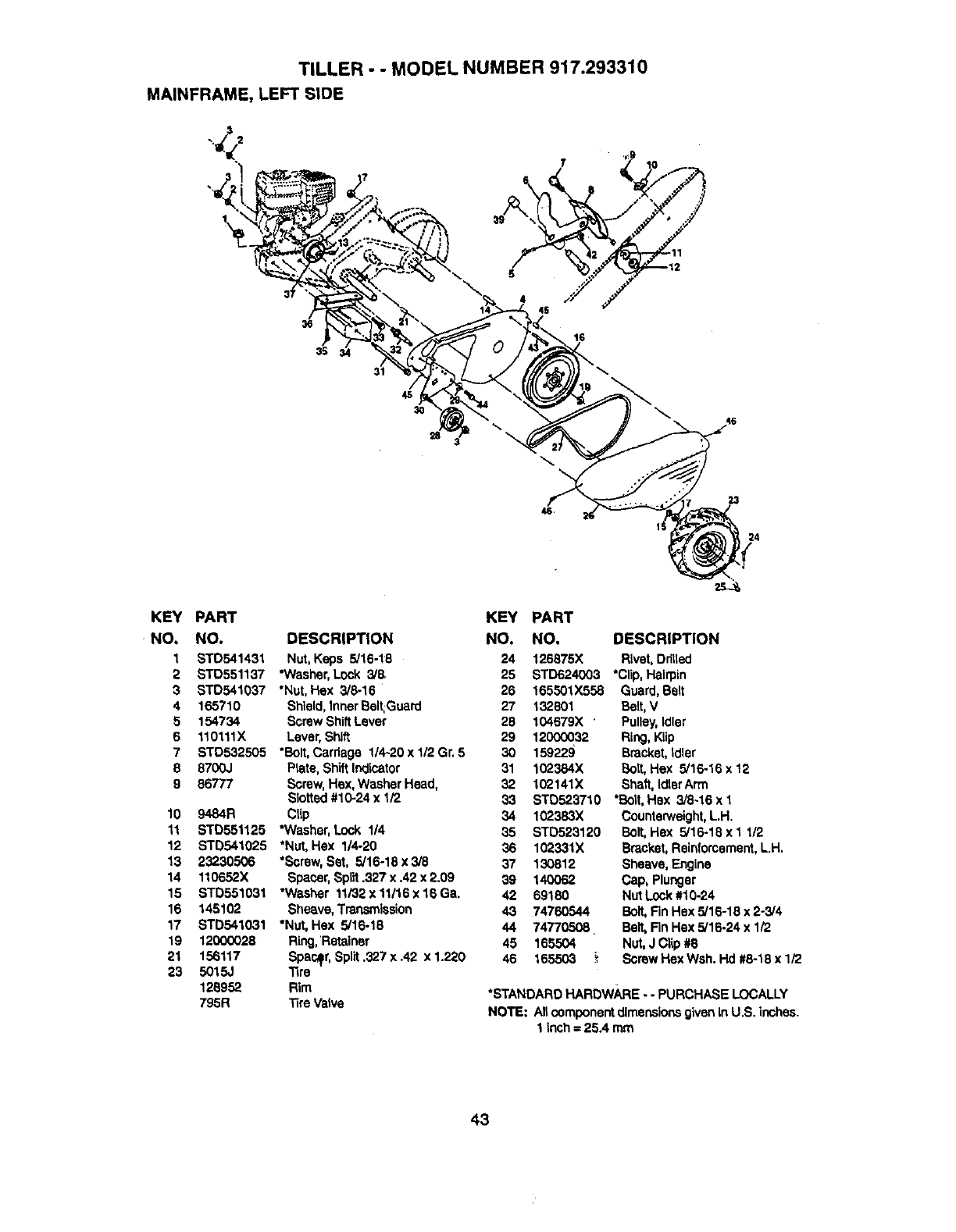
TILLER - - MODEL NUMBER 917.293310
MAINFRAME, LEFT SIDE
$
16
45
30
23
24
KEY PART
NO, NO. DESCRIPTION
1 STD541431 Nut, Keps 5/16-18
2 STD551137 "Washer,Lock 3/5
3 STD541037 "Nut, Hex 3/8-16
4 165710 Shield,Inner Belt:Guard
5 154734 Screw ShiftLaver
6 110111X Lever, Shift
7 STD532505 *Bolt,Cardage 1/4-20 x 1/2 Gr. 5
8 8700J Ptata,ShiftIndicator
9 86777 Screw,Hex, Washer Head,
Slotted #10-24 x 1/2
10 9484R Clip
11 STD551125 *Washer,Lock 1/4
12 STD541025 *Nut, Hex 1/4-20
13
14
15
16
17
19
21
23
23230506 *Screw,Set, 5/16-18 x 3/8
110652X Spacer,Split .327 x .42 x 2.09
STD551031 "Washer 11/32x11116x16Ga.
145102 Sheave, Transmission
STD541031 "Nut, Hex 5/16-18
12000028 Ring, Retainer
156117 Spacer, Spilt.327 x .42 x 1.220
5015J 1ire
128952 Rim
795R "_reValve
KEY
NO.
24
25
26
27
28
29
3O
31
32
33
34
35
36
37
39
42
43
44
45
46
PART
NO. DESCRIPTION
165501)(558
132801
104679X '
12000032
159229
102384X
102141X
126875X Rivet,Ddlled
STD624003 *Clip,Hairpin
Guard,Belt
Belt,V
Pulley,Idler
Ring, Klip
Bracket,Idler
Bolt, Hex 5/16.16 x 12
Shaft, IdtarArm
STD523710 *Bolt, Hex 3/8-16 x 1
102383X
STD523120
102331X
130812
14OO62
69180
74760544
74770508.
165504
165503
Counterweight,L.H.
Bolt,Hex 5/16-18 x1112
Bracket,Reinforcement,LH.
Sheave, Engine
Cap, Plunger
Nut Lock#10-24
Bolt,Fin Hex 5/16-18 x 2-3/4
Belt,Rn Hex 5/15-24 x 1/2
Nut, J Clip #8
Screw Hex Wsh. Hd #8-18 x 1/2
*STANDARD HARDW_:IE -- PURCHASE LOCALLY
NOTE: Allcomponentdimensions given in U.S. inches.
1inch = 25.4 mm
43
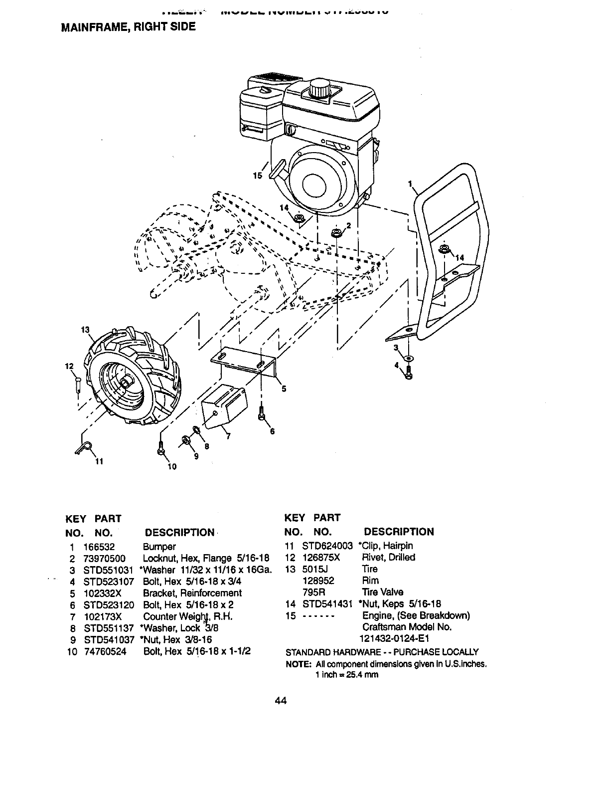
MAINFRAME, RIGHT SIDE
13
12
y
11
15
6
/,/
KEY PART
NO. NO. DESCRIPTION
1166532 Bumper
2 73970500 Locknut,Hex, Flange 5/16-18
3 STD551031 *Washer 11/32 x 11/16 x 16Ga.
4 STD523107 Bolt,Hex 5/16-18x3/4
5 102332X Bracket, Reinforcement
6 STD523120 Bolt,Hex 5/16-18x2
7 102173X CounterWeigh, R.H.
8 STD551137 *Washer, Lock 3/8
9 STD541037 *Nut, Hex 3/8-16
10 74760524 Bolt,Hex 5/'16-18 x 1-1/2
KEY PART
NO. NO. DESCRIPTION
11 STD624003 *Clip, Hairpin
12 126875X Rivet, Drilled
13 5015.1 _re
128952 Rim
795R Tire Valve
14 STD541431 *Nut, Keps 5/16-18
15 ...... Engine, (See Breakdown)
Craftsman Model No.
121432-0124-E1
STANDARDHARDWARE-- PURCHASELOCALLY
NOTE:AllcomponentdimensionsgiveninU.S.inches.
1inch=25,4 mm
44
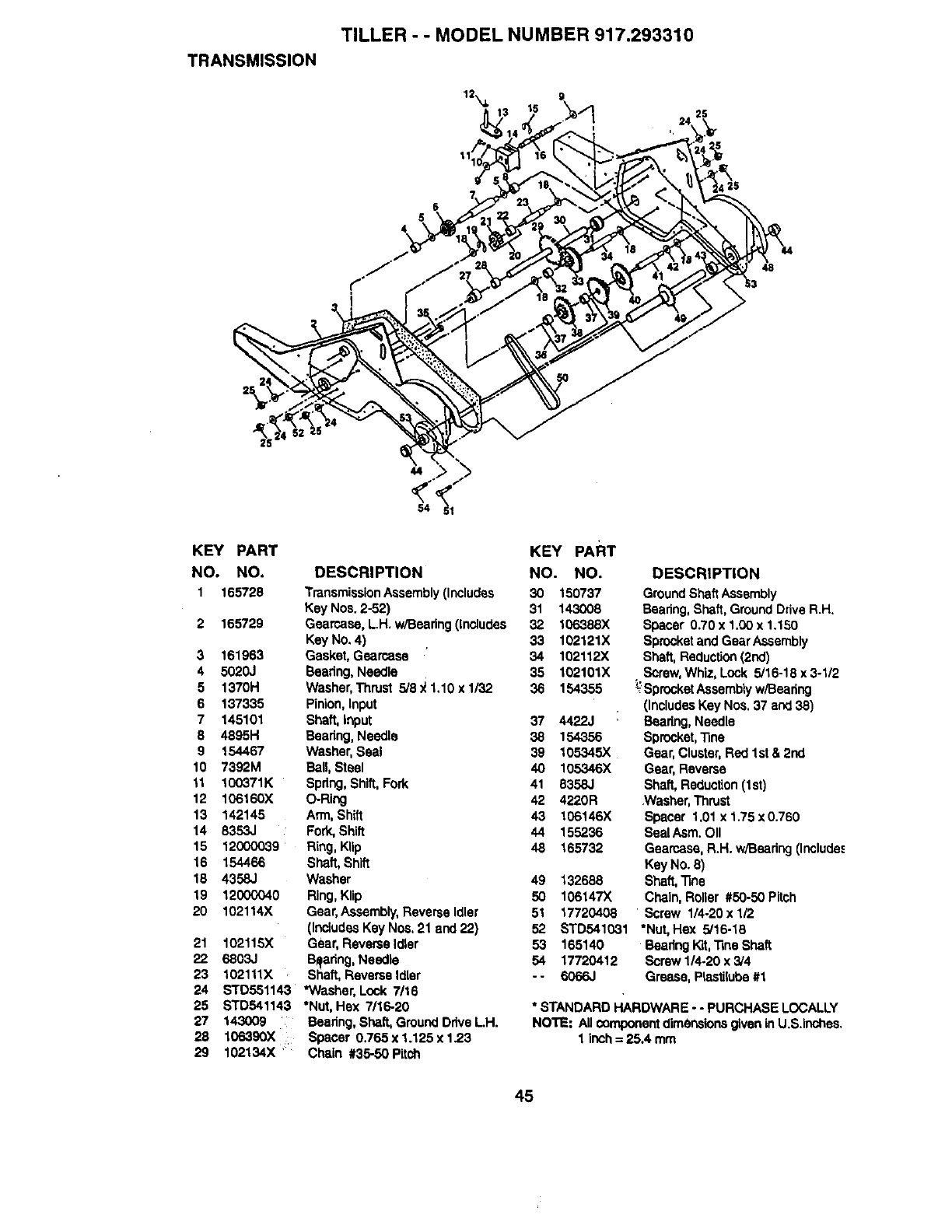
TRANSMISSION
TILLER --MODEL NUMBER 917.293310
12_, g
44
54
KEY PART
NO. NO.
1 165728
2 165729
3 161963
4 5020J
5 1370H
6 137335
7 145101
8 4895H
9 154467
10 7392M
11 100371K
12 106160X
13 142145
14 8353,.I
15 12000039
16 154466
18 4358J
19 12000040
20 102114){
21 102115X
22 6803J
23 102111X
24 STD551143
25 STD541143
27 143009
28 106390X
29 102134X
DESCRIPTION
TransmissionAssembly(Includes
Key Nos. 2-52)
Gearcase, L.H. w/Bearing(includes
Key No. 4)
Gasket, Gearcese
Beadng, Needle
Washer,Thrust 5/9 _1,10 x 1/32
Pinion, Input
Shaft, input
Bearing,Needle
Washer,Seal
Ball, Steel
Spring,Shift,Fork
O-Ring
Arm, Shift
Fork,Shift
Ring,Klip
Shaft,Shift
Washer
Ring,Klip
Gear,Assembly,Reverse Idler
(IncludesKey Nos, 21 and 22)
Gear, ReverseIdler
=B_haadng,Needle
ft, Reverse Idler
*Washer, Lock 7/16
*Nut, Hex 7/16-20
Bearing,Shaft, GroundDriveL.H.
Spacer 0,765 x 1.125 x 1.23
Chain #35-50 Pitch
KEY PART
NO. NO. DESCRIPTION
30 150737
31 143008
32 106388X
33 102121X
34 102112X
35 102101X
36 154355
37 4422J
38 154356
39 105345X
40 105346X
41 8358,.I
42 4220R
43 106146X
44 155236
48 165732
49 132688
50 106147X
51 17720408
52 STD541031
53 165140
54 17720412
"" 60_6J
GroundShaftAssembly
Bearing,Shaft,GroundDriveR.H.
Spacer 0.70 x 1,00x 1.150
Sprocketand Gear Assembly
Shaft, Reduction(2nd)
•Screw,Whiz, Lock 5/16-18 x 3-1/2
SprocketAssembly w/Beadng
(IncludesKey Nos. 37 and 38)
Baaring, Needle
Sprocket,_ne
Gear, Cluster,Red 1st & 2nd
Gear, Reverse
Sha_ Reduction(1st)
.Washer,Thrust
Spacer 1.01 x 1.75 x 0.760
Seal Asm. OII
Gearcase, R.H. w/Besring(Include._
Key No. 3)
Shaft,Tins
Chain, Roner #50-50 Pitch
Screw 1/4o20x 1/2
*Nut, Hex 5/16-16
BeadngKit,"RneShaft
Screw 1/4-20 x 3/4
Grease, P_Lstiluloe#1
* STANDARD HARDWARE --PURCHASE LOCALLY
NOTE: All componentdimensionsgiveninU.S.inchea.
1 inch= 25.4 mm
45
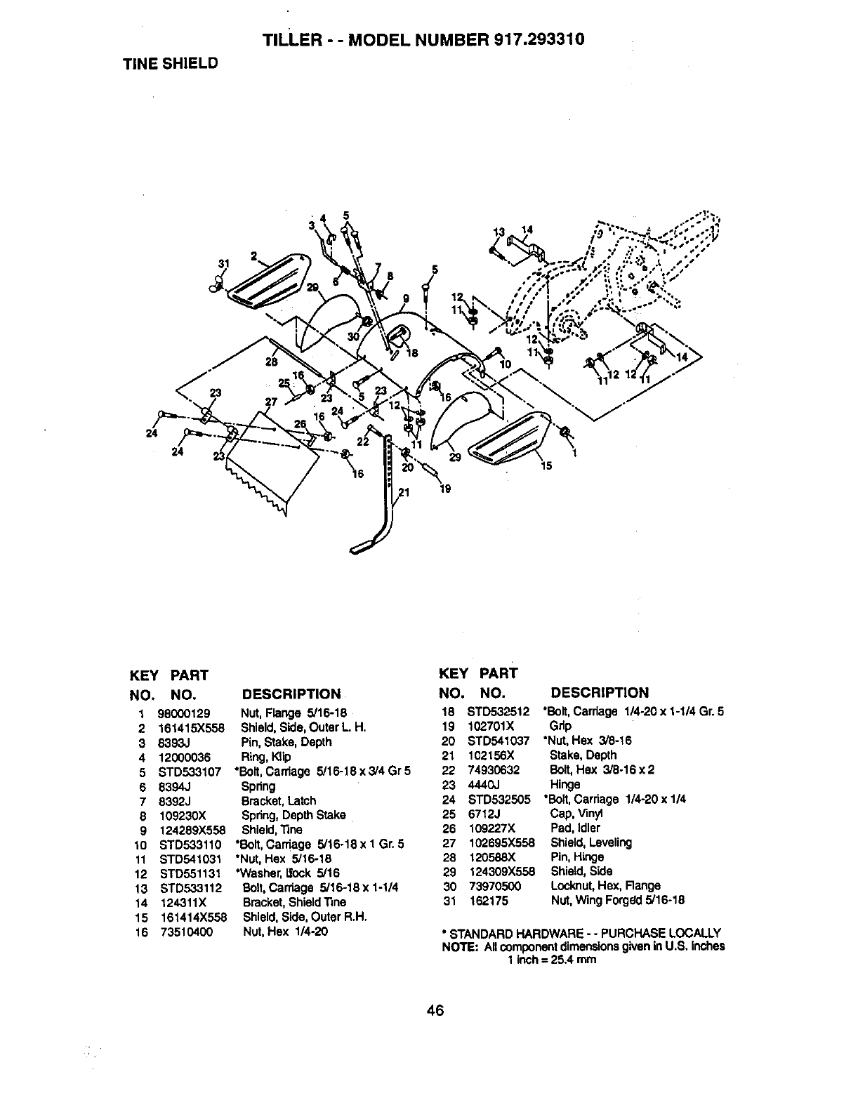
TINE SHIELD
TILLER - - MODEL NUMBER 917.293310
5
14
24 /0=_....
24 1
15
KEY PART
NO. NO.
1 98000129
2 161415X558
3 8393J
4 12000036
5STD533107
6 8394J
7 8392J
8109230X
9 124289X558
10 STD533110
11 STD541031
12 STD551131
13 STD533112
14 124311X
15 161414X558
16 73510400
DESCRIPTION
Nut, Flange 5/16-18
Shield, Side,Outer L. H,
Pin, Stake, Depth
Ring,Klip
*Bolt,Carriage 5/16-18 x 3/4 Gr 5
Spring
Bracket,Latch
Spring, Depth Stake
Shield,"nne
*Bolt,Carriage 5/16-18 x I Gr. 5
*Nut, Hex 5/16-18
*Washer,_ock 5/16
Bolt,Carriage 5/16-18 x 1-1/4
Bracket,Shieldline
Shield,Side, Outer R.H.
Nut, Hex 1/4-20
KEY PART
NO. NO. DESCRIPTION
18
19
20
21 102156X Stake, Depth
22 74930632 Bolt,Hex 3/8-16x2
23 4440J Hinge
24 STD532505 *Bolt,Carriage 1/4-20 x 1/4
25 6712J Cap, Vinyl
26 109227X Pad, Idler
27 102695X558 Shield,Leveling
28 120588X Pin, Hinge
29 124309X558 Shield,Side
30 73970500 Locknut,Hex, Range
31 162175 Nut, Wing Forgr=Jd5/16-18
STD532512 *Bolt,Carriage 1/4-20 x 1-1/4 Gr. 5
102701X Grip
STD541037 *Nut, Hex 3/8-t6
• STANDARDHARDWARE - -PURCHASE LOCALLY
NOTE: Ancomponentdimensionsgivenin U.S, inches
1 inch= 25A mm
46
TILLER --MODEL NUMBER 917.293310
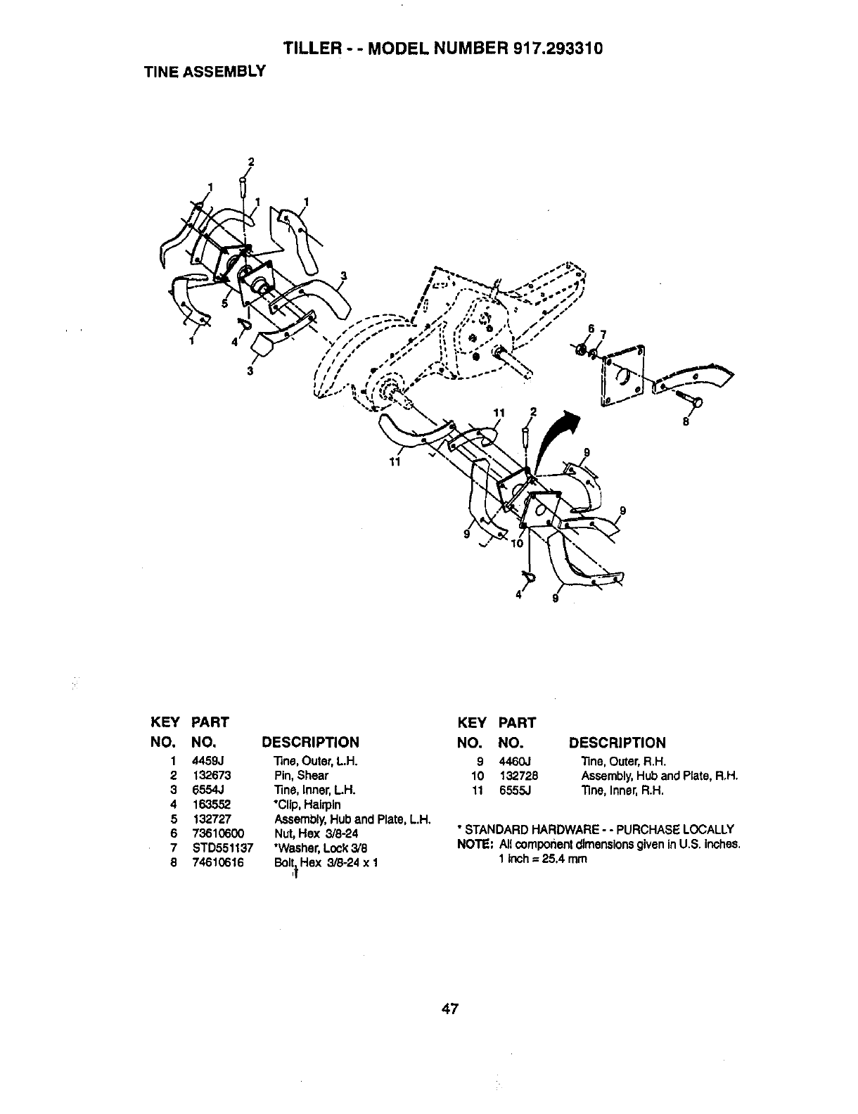
TINE ASSEMBLY
2
1
1
1 4
11
11 8
9
KEY
NO.
1
2
3
4
5
6
7
8
PART
NO.
4459J
132673
6554J
163552
132727
73610600
STD551137
74610616
DESCRIPTION
"13ne,Outer, L.H.
Pin, Shear
line, Inner,L.H.
*Clip, Hairpin
Assembly,Hub and Plate, L.H.
Nut, Hex 3/8-24
*Washer,Lock3/8
Bolt.Rex 3/8-24 x 1
,t
KEY PART
NO. NO. DESCRIPTION
9 4460J Tine, Outer, R.H.
10 132728 Assembly,Hub and Rate, R.H.
11 6555J "13ne,Inner.R.H.
• STANDARD HARDWARE - - PURCHASE LOCALLY
NOTE: Allcomponentdimensionsgiven inU.S. inches.
1 inch=25.4 mm
47
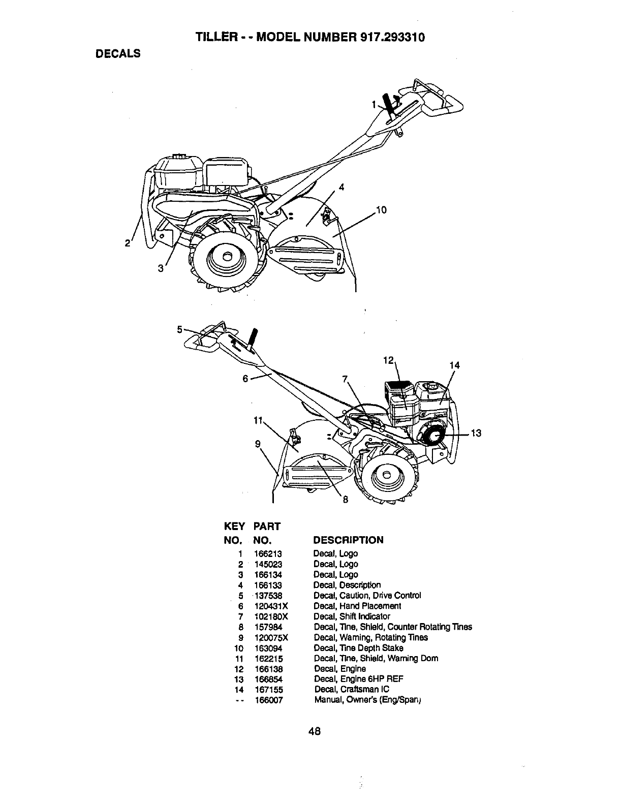
DECALS
TILLER - - MODEL NUMBER 917.293310
12 14
9\
KEY PART
NO. NO. DESCRIPTION
1 166213 Decal, Logo
2 145023 Decal, Logo
3 166134 Decal, Logo
4 166133 Decal, Description
5 137538 Decal, Caution,Drive Control
6 120431X Decal, Hand Placement
7 102180X Decal, Shift Indicator
8 157984 Decal, Tine, Shield,Counter RotatingTines
9 120075X Decal, Warning, RotatingTines
10 163094 Decal, Tine DepthStake
11 162215 Decal, Tine, Shield,Warning Dom
12 166138 Decal, Engine
13 166854 Decal, Engine6HP REF
14 167155 Decal, Cm,ftsmanIC
- - 166007 Manual,Owner's (Eng/Span}
48
TILLER - - MODEL NUMBER 917.293310
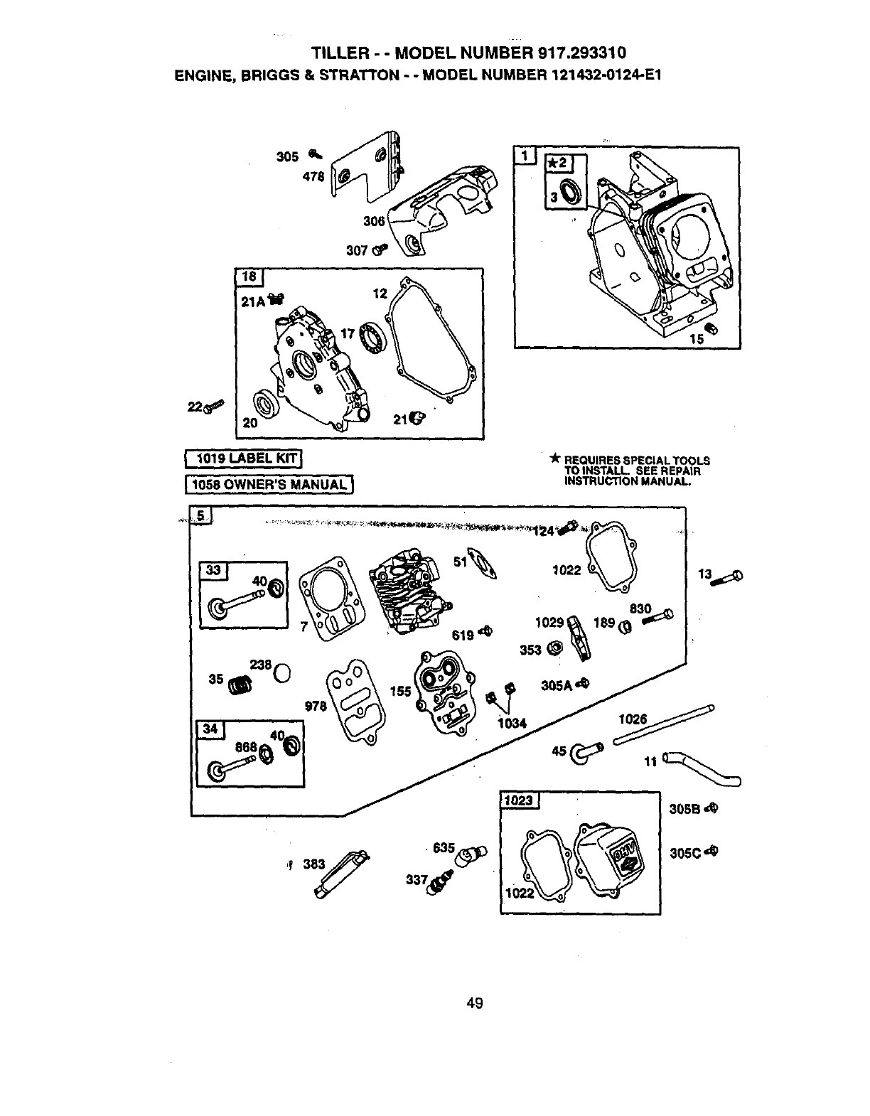
ENGINE, BRIGGS & STRATTON - -MODEL NUMBER 121432-0124-E1
I1010 LABEL KIT I
[ 1058 OWNER'S MANUAL I
"k REQUIRES SPECIAL TOOLS
TO INSTALL.. SEE REPAIR
INSTRUCTION MANUAL
33 40 ,022_j
619 ,d_
13.._
49
TILLER - -MODEL NUMBER 917.293310
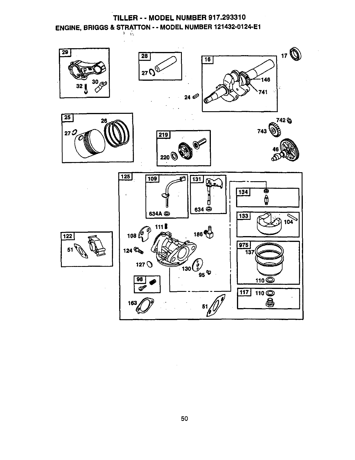
ENGINE, BRIGGS & STRATTON - - MODEL NUMBER 121432-0124-E1
27_
24
634
634A _)
111 II 186_
124 _,
127
5O
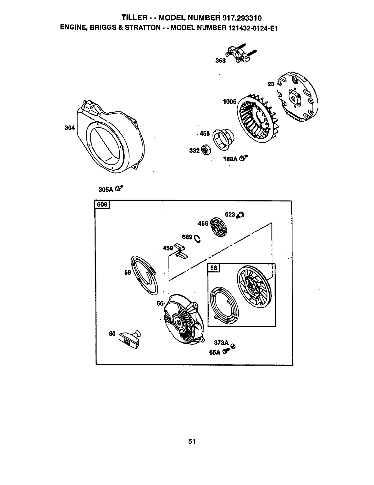
TILLER --MODEL NUMBER 917.293310
ENGINE, BRIGGS & STRATTON --MODEL NUMBER 121432-0124-E1
23
1005
3O4
305A_
55
51
TILLER - - MODEL NUMBER 917.293310
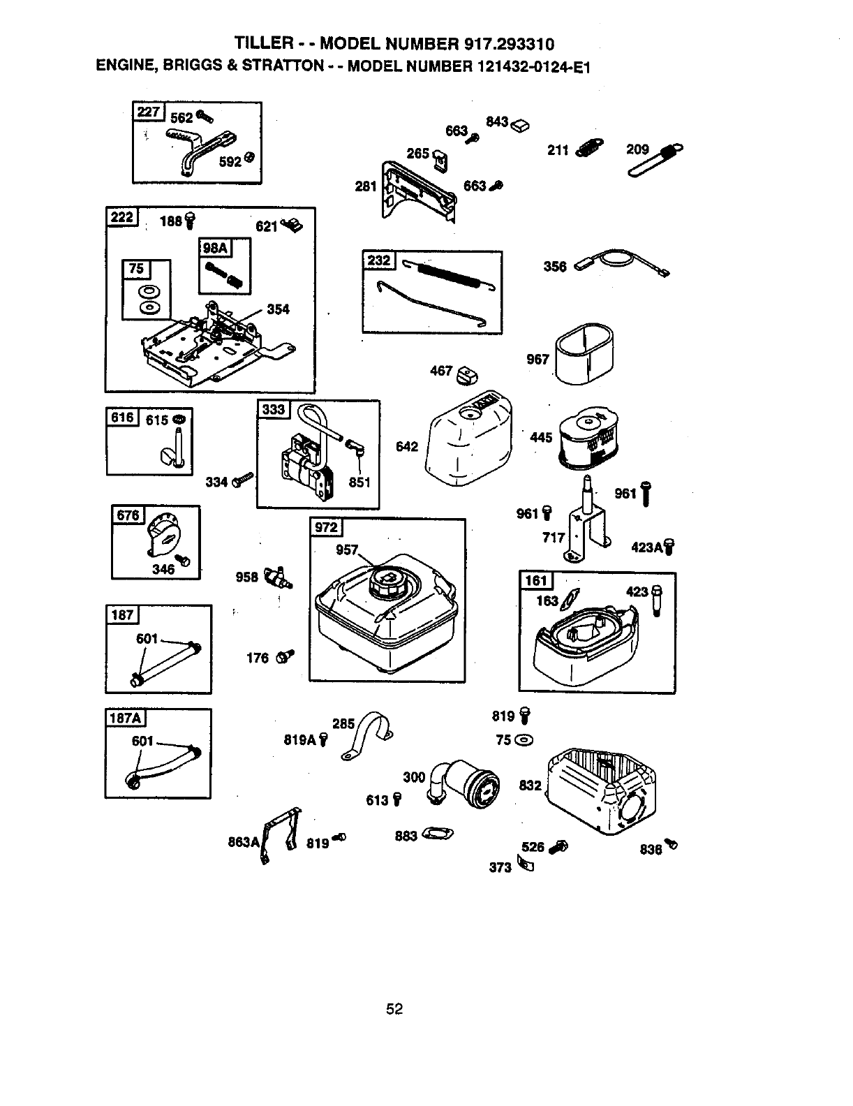
ENGINE, BRIGGS & STRATI'ON -- MODEL NUMBER 121432-O124-E1
22211 188_ 621<1q_
281 _663 J)
4e7
3ss_
967
ssa
!
176
863A_ 819 _883 _;_ 526
373 _3
838_
52
TILLER - - MODEL NUMBER 917.293310
ENGINE,BRIGGS& STRATTON..- MODEL NUMBER 121432-0124-E1
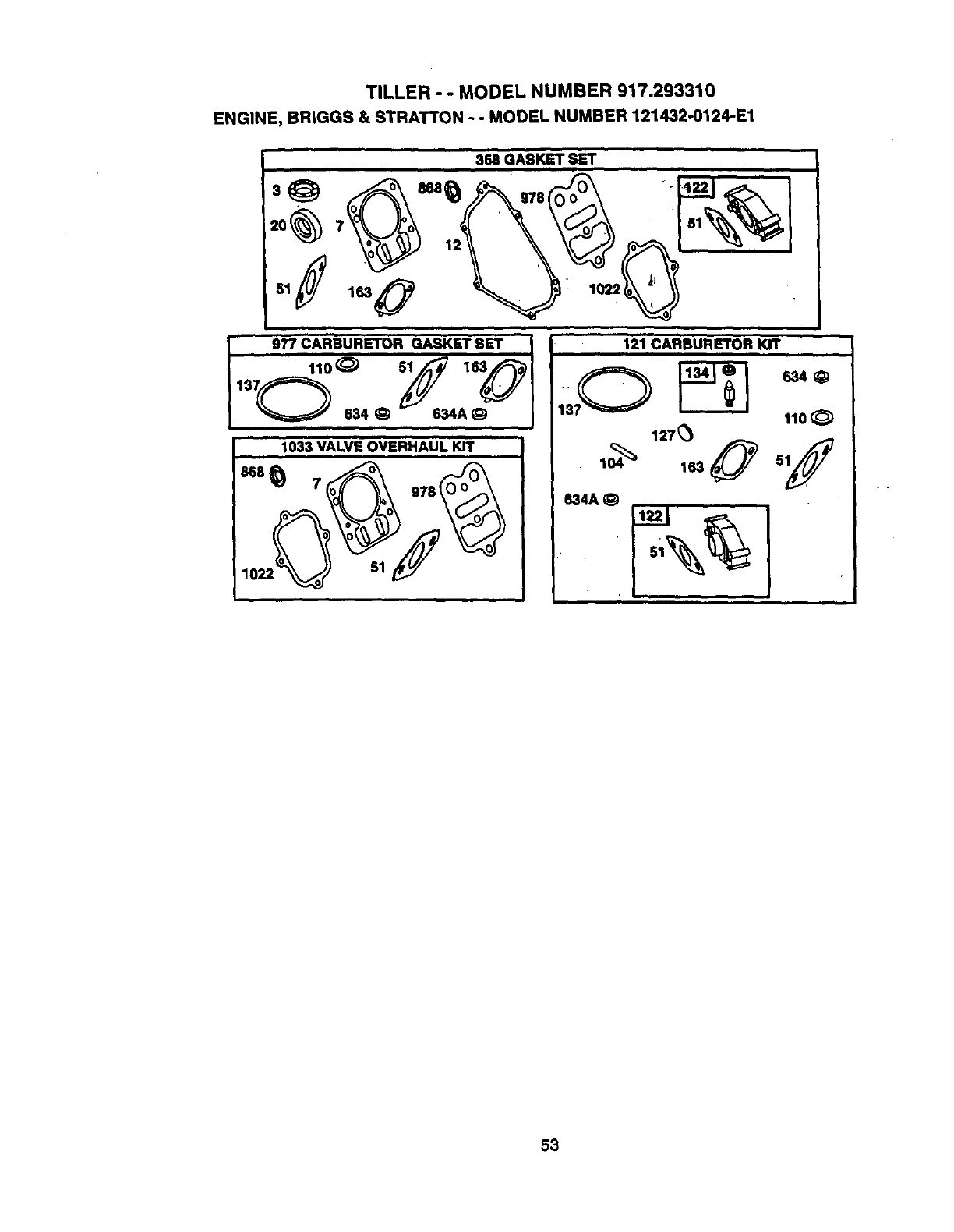
i inn i
358 GASKET SET
'°_' j"N_
51/ 1630"__!' ;,_
977 CARBURETOR GASKET SET 121 CARBURETOR KIT
nl
11°° 9
51 163
O634_ A 11o_
127_,.0 'Y
1033 VALVE OVERHAUL KIT
i,n . , , , •
B34A 0
53
TILLER -- MODEL NUMBER 917.293310
'ENGINE, BRIGGS & STRATFON - - MODEL NUMBER 121432-0124-E1
KEY PART _ " KEY PART
NO. NO, DESCRIPTION NO. NO. DESCRIPTION
1 690045 CylinderAssembly 109 693628 Choke Shaft
2 399269 Bushing,Cylinder 110 -- -- tO Washer, Seal (sold In Kit Only)
3 299819 * Seal, Oil 111 262715 SpdngFrictlon(Choks)
5 693643 Head, Cylinder 117 690048 Jet, Main (Standard)
7 273489 &'Jr Gasket, CylinderHead 121 690032 Carburetorkit
11 693647 Tube, Breaker 122 690043 -k Spacer,Carburetor
12 692549 "JrGasket, Crankcase 124 692566 Screw,Carburetor
13 95049 Screw,CylinderHead 125 693518 Carburetor
15 94916 Plug, OilDrain 127 --- • Plug, Welch (sok:linKit Only)
16 693403 Crankshaft 130 223470 Valve Throttlai
17 498185 Bearing,Ball 131 690024 ShaftThrotUe
18 693204 CovapCrankcase 133 398187 RoatCarburator
20 692550 "JrSeal, Oil 134 398188 •Valve, Needle
21 281658 Cap, Oil Fill 137 -- -- '_• Gasket FloatBawl (Sold In Kit
21A 693463 Cap,Oil FlU Only)
22 692551 Screw,Crankcase Cover 146 94388 Kay,Timing
23 692987 Flywheel 155 225430 Plate,CylinderHead
24 222698 Key, Flywheel 161 693459 Base, AirCleaner
25 499627 PistonAseembl_/(Stcl.) 163 272948 ,•'/r Gasket,AirCleaner
692788 PistonAssembly,.0_0' OiS 176 94905 Screw, Shoulder
692789 PistonAssembly,.020• O/S 186 493496 Connector,Hose
692790 PistonAssembly,.030"O/S 187 298049 Line, Fuel (Cut to Required
26 499631 Ring Set, (Std.) Length)
692785 Ring Set, .010"O/S 187A 692601 Line, Fuel (Molded)
692786 Ring Set, .020" O/S 188 94644 Screw, ControlBracket
692787 Ring Set, .030" O/S 188A 692590 Screw,Shoulder
27 263190 Lock, PistonPin 189 263109 Ball, Rocker/Vm
29 499423 Pin, Piston 209 693710 Spring,Governor
29 690124 Rod, Connecting 211 693710 Spdng,GovernorIdle
30 225279 Dipper,ConnectingRod 219 693578 Gear Governor
32 94699 Screw,ConnectingRod 220 221551 Washer-Thrust
33 499642 Valve, Exhaust _222 693405 Bracket,Control
34 499641 Valve,Intake 227 499506 Lever,Governor
35 263149 Spring,Valve 232 693408 Spring, Link,Mechanical
40 93312 Retainer,Valve Governor
45 262679 Tappet,Valva
46 693404 Camshaft RPM Settings Low 1650-1850; High: 3500-3700.
51 692555.1<_z_ Gasket, intake
55 497442 Housing,Rewind Starter -/rIncludedinGasket Set, Ref Number 358.
'56 498144 Pulley, Starter
58 280399 Rope, Starter •IncludedinCarburetorKit,Ref Number 121.
60 281101 Gdp, Starter Rope
65 692608 Screw, Hex. •IncludedinCarburetorGasket Set, Ref Number
65A 94904 Screw,Hex. 977.
75 495659 Washer,Sat
95 94098 Screw,ChokelSIotted AIncludedinValue OverhaulKit, RefNumber
98 398185 Screw,IdlaSpeed _1033.
98A 493280 Screws Idle Speed _r, NOTE: Allcomponentdimensionsare given in U.S.
104 231371 •Pin, FloatHinge Inches. 1 inch= 25.4 mm
108 223471 Valve, Choka
54
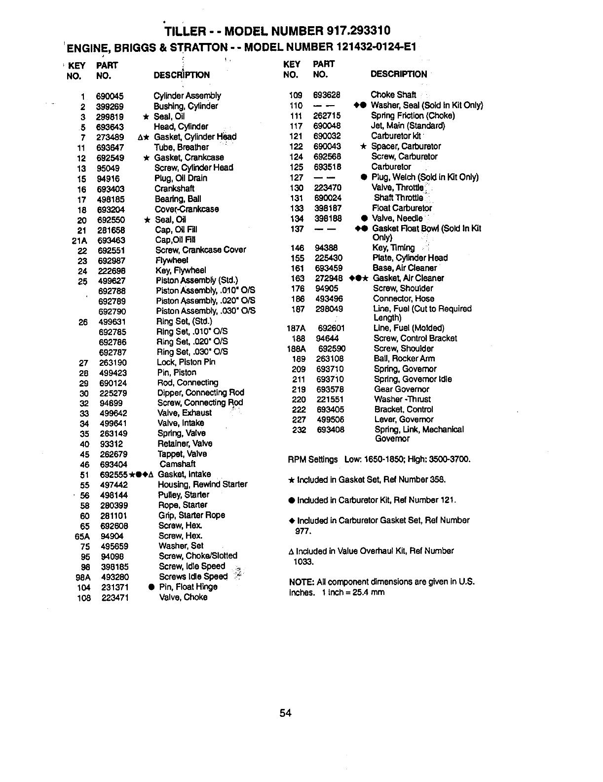
TILLER - - MODEL NUMBER 917.293310
ENGINE, BRIGGS & STRATTON --MODEL NUMBER 121432-0124-E1
KEY PART KEY PART
NO. NO. DESCRIPTION NO. NO. DESCRIPTION
238 263131 Cop,Valve
265 221535 Clamp, Casing
281 693407 Panel, Control
285 692595 Strap, Muffler
300 693593 Muffler,Exhaust
304 693621 Housing,Blower
305 692577 Screw,Panel
305A 690960 Screw,BlowerHousing
306B 692557 Screw, RockerCover 3/8" Long
305(3 94786 Screw,RockerCover 7/16" Long
306 693610 Shield,Cylinder
307 94515 Screw,CylinderShield
332 94877 Nut, Flywheel
333 692605 Armature,Magneto
334 94731 Screw, ArmatureMagneto
337 491055 Spark Plug
346 94896 Screw
353 95137 Nut-Hex
354 692575 Nut, Lock
356 398808 Wire, Stop
358 690031 Gasket Set
363 19069 FlywheelPuller
373 692582 Nut, Clip
373A 94907 Nut, Hex.
383 19374 Wrench, SparkPlug
423 94655 Screw,AirCleaner Base
423A 94929 Screw,AirCleaner Base
445 498596 FifferNC Cortddge
455 225457 Cup, Flywheel
456 281503 Retainer,Spdng
459 281505 Pawl, Ratchet
467 493903 Knob,AirCleaner
478 693709 Panel
526 94974 Screw
562 94852 Bolt,GovernorLever
592 231082 Nut, GovernorLever
601 9.30.53 Clamp, Hose
608 497830 Starter,Rewind
613 94706 Screw,MufflerMounting
615 94672 Retainer,Governor
616 692547 Crank, Governor
619 94744 Screw, Cyl. Head Plate
621 396847 Switch,Stop
623 94943 Screw, Shoulder
634 -- -- ._ WacherSold inKit Only)
634A -- -- 4,O Washer(Sold lnK]tOnly)
63s 8o5529 Boot,SparkP_
642 693460 Cover, Air Cleaner
663 692577 Screw,cos_ C_mp
676 393757 Defleet.or,Muffler
689 263073 Spdng, Frtc_an
717 693462 AirCleaner Bracket
741 263157 Gear, lbning
742 692564 Ring,Retaining
743 692566 Gear, Idler
819 6_.598 Screw,MuilierStrap
819A 94914 Screw
830 94993 Screw-Hex.
832 693583 Guard,Muffler
836 94896 Screw, MufflerGuard
836A 692596 Bracket,Muffler
851 493880 Terminal,Cobie
863A 692596 Bracket,Muffler
868 498592 A* Seal, Valve
883 272309 Gasket,Exhaust
957 493988 Cop, Fuel Tank
958 692586 Valve, Shutoff
961 963598 Screw, AirCleaner Bracket
967 273356 Fiffer,Air Pre-Cleaner
972 692587 Tank, Fuel
975 493640 Bowl,Float
977 690033 Gasket Set, Carburetor
978 273346 A* Gasket,Plate
1005 692592 Fan, Flywheel
1019 690035 LabelKit
1022 273241 A* Gasket, Rockercover
1023 499924 Cover, Rocker
1026 693517 Rod,Push
1029 225246 Arm,Rocker
1033 690034 Kit,Valve Overhaul
1034 281621 Guide, Push ROd
1058 273700 Owner'sManual
- - - Replacement Engine 121432-
0036-E2
ReplacementS/B notavailable
at thistime
RPM Settings Low: 1650-1850; High: 3500-3700.
* Included in Gasket Set, Ref Number 358.
• Included in Carburetor Kit, Ref Humber 121.
•Included in Carburetor Gasket Set, Ref Number
977.
AIncluded in Value Overhaul Kit, Ref Number
1033.
NOTE: All component dimensions ere given in U.S.
inches. 1 inch = 25.4 mm
55
Forthe repairor replacementpartsyouneed
delivereddirectlyto yourhome
Call7 am- 7 pro,7 daysaweek
1-800-366-PART
(1-800-366-7278)
Para ordenar piezas con entrega a
domicilio - 1-800-659-7084
For in-house major brand repair service
Call 24 hours aday, 7 days a week
1-800-4-REPAIR
(1-800-473-7274)
Para pedir servicio de reparaci6n a
domicilio - 1-800-676-5811
For the location of a Sears Parts and
Repair Center in your area
Call 24 hours a day, 7 days aweek
1-800-488-1222
For information on purchasing a Sears
Maintenance Agreement or to inquire
about an existing Agreement
Call 9 am - 5 pm, Monday-Saturday
1-800-827-6655
Imimm_
mmmmmm
When requesting service or ordering
parts, always provide the following
information:
•Product Type •Part Number
°Model Number •Part Description SEARS
Amenca's Repair Specialists
166007 Rev. 1 11.4.98 TR Printed in U.S.A.
