Craftsman Chipper Vac Riding Mower Attachment Owners Manual
2015-03-28
: Craftsman Craftsman-Chipper-Vac-Riding-Mower-Attachment-Owners-Manual-662054 craftsman-chipper-vac-riding-mower-attachment-owners-manual-662054 craftsman pdf
Open the PDF directly: View PDF ![]() .
.
Page Count: 28
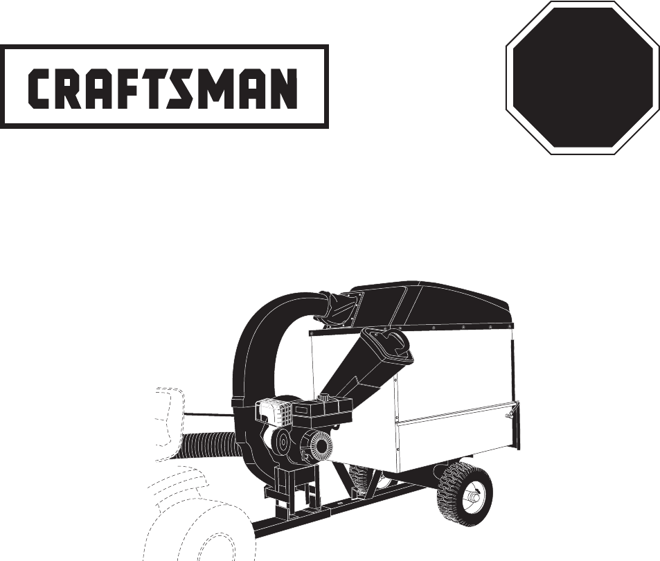
Operator's Manual
Model No's. 486.25013
CHIP-N-VAC
®
PRINTED IN U.S.A. FORM NO. 42486 (05/08/12)
Sears, Roebuck and Co., Hoffman Estates, IL 60179 U.S.A.
www.sears.com/craftsman
CAUTION:
Before using this product, read
this manual and follow all Safety
Rules and Operating Instructions.
• Safety
• Assembly
• Operation
• Maintenance
• Parts
STOP
DO NOT RETURN TO STORE
For Missing Parts or Assembly
Questions Call 1-866-576-8388
IMPORTANT: The engine is shipped without oil. Add oil before starting
the engine.
IMPORTANT: The wheel bearings are not pre-lubricated.
Fill the wheel hubs with grease after assembling the wheels to the axle.

2
TABLE OF CONTENTS
WARRANTY ................................................................2
SAFETY RULES ..........................................................3
FULL SIZE HARDWARE CHART ................................6
CARTON CONTENTS .................................................7
ASSEMBLY ..................................................................8
OPERATION ..............................................................16
MAINTENANCE ........................................................18
SERVICE AND ADJUSTMENTS ...............................19
STORAGE .................................................................19
TROUBLESHOOTING ...............................................20
REPAIR PARTS ILLUSTRATIONS .................23,24,26
REPAIR PARTS LISTS ....................................23,25,26
SLOPE GUIDE ..........................................................27
PARTS ORDERING/SERVICE ....................Rear Cover
WARRANTY
CRAFTSMAN FULL WARRANTY
FOR ONE YEAR from the date of purchase, this product is warranted against defects in material or workmanship. A
defective product will receive free in-home repair or replacement if repair is unavailable.
WARRANTY SERVICE
For warranty coverage details to obtain free repair or replacement, call 1-800-659-5917 or visit the web site: www.
craftsman.com
All of the above warranty coverage is void if this riding equipment is ever used while providing commercial services or if
rented to another person.
This warranty covers ONLY defects in material and workmanship. Warranty coverage does NOT include:
• Expendablepartsthatcanwearoutfromnormalusewithinthewarrantyperiod,includingbutnotlimitedtospark
plugs,aircleaners,belts,andoillters.
• Standardmaintenanceservicing,oilchanges,ortune-ups.
• Tirereplacementorrepaircausedbypuncturesfromoutsideobjects,suchasnails,thorns,stumps,orglass.
• Tireorwheelreplacementorrepairresultingfromnormalwear,accident,orimproperoperationormaintenance.
• Repairsnecessarybecauseofoperatorabuse,includingbutnotlimitedtodamagecausedimpactingobjectsthat
bend the frame, axle assembly or crankshaft, or over-speeding the engine.
• Repairsnecessarybecauseofoperatornegligence,includingbutnotlimitedto,electricalandmechanicaldamage
caused by improper storage, failure to use the proper grade and amount of engine oil, failure to keep the product clear of
ammabledebris,orfailuretomaintaintheequipmentaccordingtotheinstructionscontainedintheoperator'smanual.
• Engine(fuelsystem)cleaningorrepairscausedbyfueldeterminedtobecontaminatedoroxidized(stale).Ingeneral,
fuel should be used within 30 days of its purchase date.
• Normaldeteriorationandwearoftheexteriornishes,orproductlabelreplacement.
Thiswarrantygivesyouspeciclegalrights,andyoumayalsohaveotherrightswhichvaryfromstatetostate.
Sears Brands Management Corporation, Hoffman Estates, IL 60179
MODEL NUMBER: 486.25013
SERIAL NUMBER: __________________
DATE OF PURCHASE: __________________
The model and serial numbers will be found on a decal
attached to the engine base.
You should record both the serial number and the
date of purchase and keep in a safe place for future
reference.

3
SAFETY
Anypowerequipmentcancauseinjuryifoperatedimproperlyoriftheuserdoesnotunderstandhowtooperatetheequipment.Exercise
caution at all times, when using power equipment.
• Readandfollowallinstructionsinthismanualbeforeattempting
to assemble or operate this equipment. Failure to comply
withtheseinstructionsmayresultinpersonalinjury.Keepthis
manual in a safe place for future reference and for ordering
replacement parts.
• Readthisoperatingandserviceinstructionmanualcarefully.
Be thoroughly familiar with the controls and proper use of this
power vacuum.
• Readthevehicleownersmanualandvehiclesafeoperation
rules before using this equipment.
• Never allow children under 16 to operate this ChipperVac.
Children 16 years and older should only operate under close
parental supervision.
• Donotallowanyonetooperatethisequipmentwithoutproper
instructions.
• Donotallowpassengerstorideonthisequipmentoronthe
towing vehicle.
• Keeptheareaofoperationclearofallpersons,particularly
small children. Also keep area clear of pets.
• Checkfuelbeforestartingengine.Donotllfueltankindoors,
or when engine is running, or while engine is hot. Wipe off any
spilled fuel before starting engine.
• Engineandmufergethot.Donottouch!Toavoidrehazard,
keep clean of debris and other accumulations.
• NeverstoreChipperVacwithfuelintank.Allowenginetocool
before storing in any enclosure.
• Donotchangeenginegovernorsettings.
• Do not operate engine if air cleaner or cover is removed,
exceptforadjustment.Removalofthesepartscouldcreatea
rehazard.
• Beforecleaning,repairingorinspecting,makecertainallmoving
parts come to a complete stop. Disconnect spark plug wire and
keepwireawayfromplugtopreventaccidentalstarting.Keep
throttle control lever in stop position.
• IftheChipperVacshouldbecomeblockedwithdebrisatany
point, shut engine off and wait until the impeller comes to a
complete stop before attempting to remove the obstruction.
Disconnect spark plug wire to prevent accidental starting.
• If the cutting mechanism strikes a foreign object, or if your
Chipper Vac should start to vibrate abnormally, stop the engine
immediately, disconnect the spark plug wire and move the wire
away from the spark plug. Allow the machine to stop and take
the following steps.
a. Inspect for damage.
b. Repair or replace any damaged parts.
c. Check for loose parts and tighten to assure
continued safe operation.
• Checkallboltsfortightnessatfrequentintervalstohelpinsure
safe operation.
• Checkvinylhardtopbootfrequentlyforwear.Replaceifworn
or damaged.
• NeveroperateChipperVacunlessdeckadapter,hose,hose
adapter(nozzle),dischargechute(elbow),chipperchuteand
top cover are properly attached in their place.
• Donotremovetopcoverorattempttoemptycontentsofcart
while engine is running.
• Neverattempttochangehoseadapter(nozzle)ortoinstall
remote hose attachment when engine is running.
• Keep all shields and guards (e.g. chipper chute, discharge
chute(elbow)andhoseadapter(nozzle)inplaceandsecurely
attached.
• Keephands,feet,face,longhairandclothingoutofinletand
discharge area. There are ROTATING BLADES inside these
openings.
• Alwayswearsafetyglassesorothersuitableeyeprotection
when operating or maintaining this equipment.
• Wearprotectivegloveswhenfeedingmaterialintothechipper
chute.Avoidloosettingclothing.
• Keepfaceandbodyclearofthechipperchutetoavoidaccidental
bounce back of any material.
• Whenfeedingmaterialintothisequipment,beextremelycareful
thatpiecesofmetal,rocks,bottles,cansorotherforeignobjects
arenotincluded.Personalinjuryordamagetothemachine
could result.
• Do not stand behind cart in exhaust discharge area while
engine is running.
• Donotoperatethisequipmentwhileintoxicatedorwhiletaking
drugs or medication that impairs the senses and reactions.
• Whenusingthisequipment,startwiththevehicletransmission
inrst(low)gearandthengraduallyincreasespeedonlyas
conditions permit.
• Operatethisequipmentatreducedspeedonroughterrain,
along creeks and ditches and on slopes to prevent tipping or
loss of control. Do not drive too close to a creek or ditch.
• Vehicle braking and stabilityareaffectedbytheadditionof
thisequipment.DonotlltheChipperVactoitsfullcapacity
without checking the capability of the towing vehicle to safely
pull and stop with the Chipper Vac attached.
• Beforeoperatingonanygrade(hill)refertothesafetyrules
inthevehicleowner'smanualconcerningsafeoperationon
slopes. Also refer to the SLOPE GUIDE on page 27 of this
owner'smanual. Do not operateon slopes in excessof10
degrees. STAY OFF STEEP SLOPES.
• Followthemaintenanceinstructionsoutlinedinthismanual.
Look for this symbol to point out important safety precautions. It means — Attention!! Become alert!! Your safety
is involved.
DANGER: This Chipper Vac was built to be operated according to the rules for safe operation in this
manual. As with any type of power equipment, carelessness or error on the part of the operator can
resultinseriousinjury.Thisunitiscapableofamputatingngersandhandsandthrowingobjects.
Failuretoobservethefollowingsafetyinstructionscouldresultinseriousinjuryordeath.
4
WARNING
• ReadOwner'sManualandallsafetylabelsonmachinebeforestartingandusingmachine.
• DoNotremovetopcoverorattempttoemptycontentsofcartwhileengineisrunning.
• DoNotstandbehindcartinexhaustdischargeareawhileengineisrunning.
• Keephands,feet,face,longhairandclothingoutofchipperinlet,vacinlet,anddischarge
area. There are ROTATING BLADES inside these openings.
• Wearapprovedsafetyglassesandgloves.Avoidloosettingclothes.
• Keeptheareaofoperationclearofallpersons,particularlysmallchildrenandpets.
• Keepallshieldsandguards(e.g.upperchipperchuteextension,dischargechute,nozzle
assembly)inplaceandsecurelyattached.
• Checkdischargebootfrequentlyforwear.Replaceifwornordamaged.
• Ifunitbecomescloggedorjammed,shutoffenginerightaway.DoNotattempttoclear
clogorjamwithenginerunning.
• Muferandenginegethotandcancauseburns.DoNotTouch.Toavoidarehazard,
keepleaves,grassandothercombustibledebrisoffhotmuferandengine.
• DoNotattempttoremoveorattachvacnozzleoroptionalHoseKitwithenginerunning.
• DoNotoperateunitunlessnozzleoroptionalHoseKitissecuredinplace.
• DoNotllgastankwhileengineisrunning.Allowenginetocoolatleast2minutes
beforerefueling.
HAZARDOUSROTATINGBLADESINSIDE.KEEPHANDSAWAYFROMALL
OPENINGS.DONOTREMOVEORATTACHHOSE,HOSEADAPTER,ELBOWOR
OPTIONALHOSEKITWHENENGINEISRUNNING!
DANGER
WARNING
This unit is equipped with an internal combustion engine and should not be used on or near unimproved forest-covered, or
grass-coveredlandunlesstheengine'sexhaustsystemisequippedwithasparkarrestermeetingapplicablelocalorstate
laws (if any). If a spark arrester is used, it should be maintained in effective working order by the operator.
In the State of California the above is required by law (Section 4442 of the California Public Resources Code). Other
statesmayhavesimilarlaws.Federallawsapplyonfederallands.Asparkarrestermuferisavailableatyournearest
engineauthorizedservicecenter.
WARNING
MUFFLER & ADJACENT AREAS
MAY EXCEED 150 F
ROTATING CUTTING BLADES.
KEEPHANDSANDFEETOUT
OF OPENINGS WHILE MACHINE
IS RUNNING.
DANGER
TO AVOID SERIOUS INJURY
5
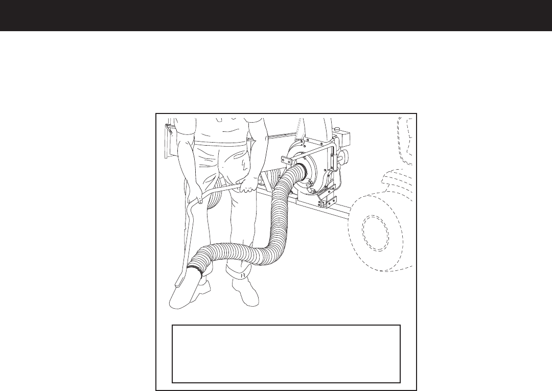
The Hand Wand Attachment, Model 486.24509
providesa12'x5"diameterhosetoclean
around shrubs, patios, window wells and other
areas not accessible to the tractor.
ACCESSORIES AND ATTACHMENTS
Theseaccessorieswereavailablewhentheunitwaspurchased.TheyarealsoavailableatmostSearsretail
outlets and service centers. Most Sears stores can order repair parts for you when you provide the model
numbersofyourtractorandChipperVacSystem.
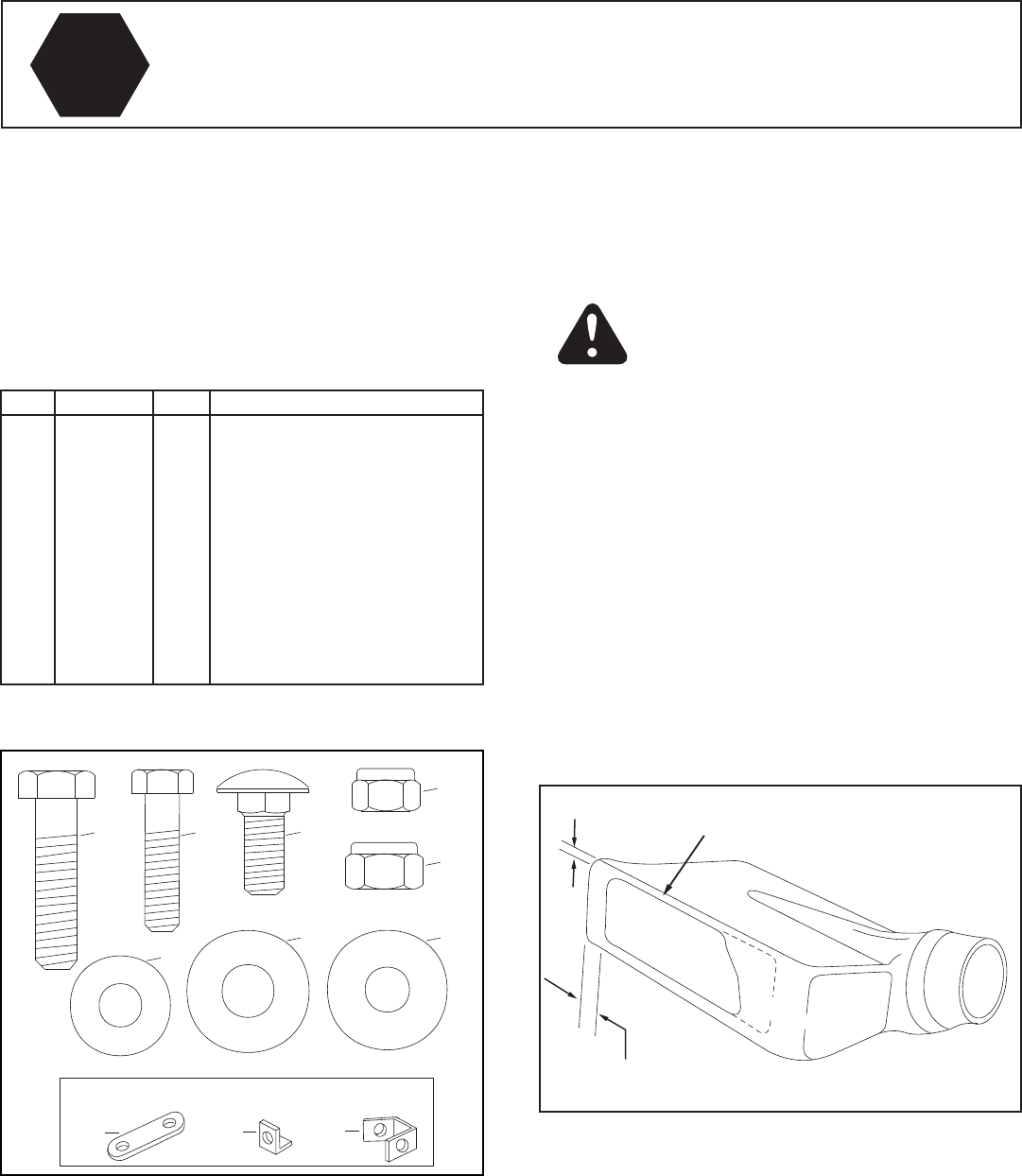
6
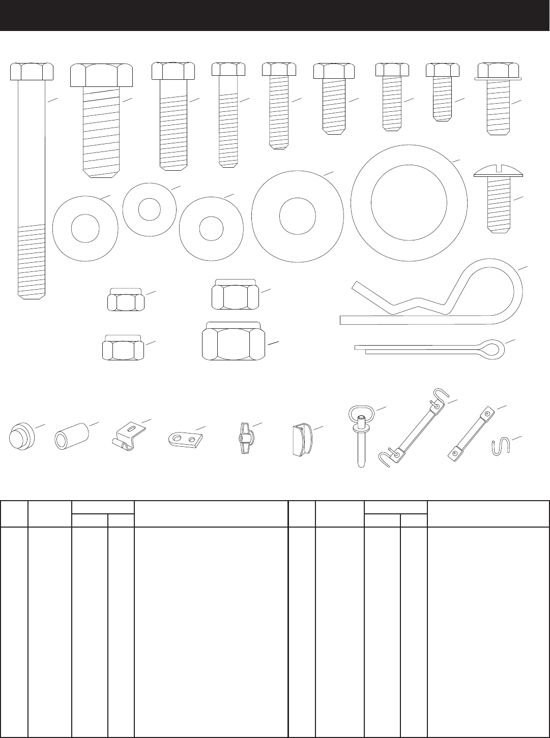
HARDWAREPACKAGECONTENTS
Seepage14fortheDeckAdapterhardwarepackage.(Contentsnotincludedhere.)
K
P
H
R
M
L
I
J
G F E D C B A
U
VWZAA
X
BB
Y
CC DD
EE
T
SHOWN FULL SIZE
Q
S
N
O
NOT SHOWN FULL SIZE
REF. PART QTY DESCRIPTION
NO. CART VAC
A 43574 3 — HexBolt,3/8"x3"
B 43351 — 1 HexBolt,1/2"x1-1/4"
C 43087 2 — HexBolt,3/8"x1-1/4"
D 1509-90 — 5 HexBolt,1/4"x1-1/4"
E 43661 — 2 HexBolt,1/4"x1"
F 43182 — 6 HexBolt,5/16"x3/4"
G 43012 — 14 HexBolt,1/4"x3/4"
H43866 9 20 HexBolt,1/4"x5/8"
I 47630 — 4 HexBolt,5/16"x3/4"Thd.Forming
J 43814 12 — TrussHeadBolt,5/16"x3/4"
K1543-69 — 6 Nylon Washer
L 43088 2 36 FlatWasher,1/4"
M 43081 — 3 FlatWasher,5/16"
N 43352 — 1 FlatWasher,7/16"
O 43601 4 — FlatWasher,1"
P 47189 9 40 NylockNut,1/4"
REF. PART QTY DESCRIPTION
NO. CART VAC
Q 47810 12 9 NylockNut,5/16"
R712-3083 — 1 NylockNut,1/2"
S HA21362 5 — NylockNut,3/8"
T 43343 1 — HairCotterPin,1/8"
U 43093 2 — CotterPin,1/8"x1-1/2"
V 43014 2 — Hub Cap
W 44678 2 — Spacer Tube
X 23838 2 — Door Support
Y 23540 — 1 Hitch Plate
Z712-0421 — 3 Knob
AA 23789 — 2 Door Latch
BB 43884 1 — Hitch Pin
CC 43790 — 1 TarpStrap,25"
DD 44850 — 4 Tarp Strap (Less Hooks)
EE 44849 — 4 "S"Hooks
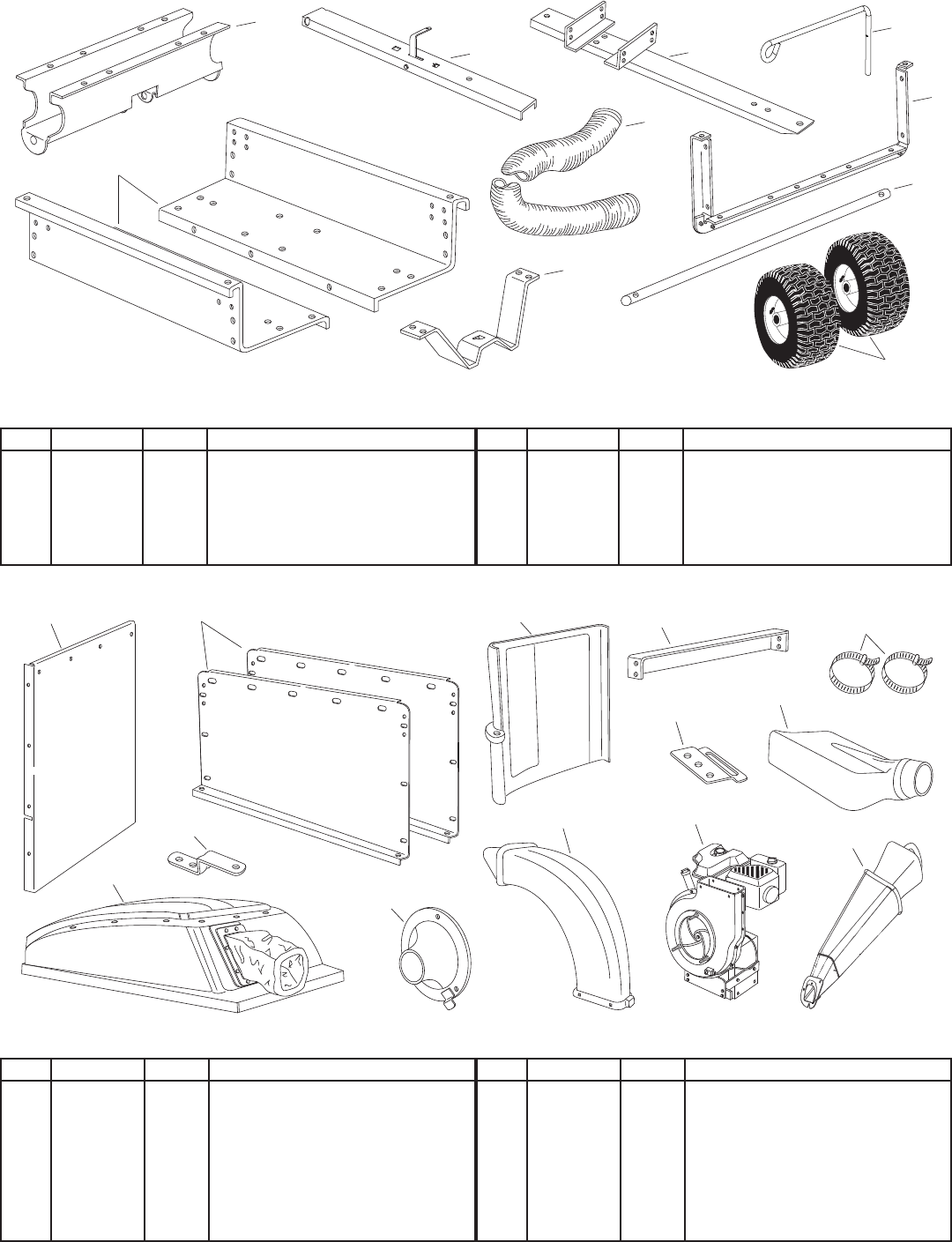
7
CARTON CONTENTS (Mow-N-Vac Carton)
CARTON CONTENTS (Cart Body Carton)
3
1 2 4
8
12
11
7
9
5
10
13
6
10
5 8
1
7
23
4
6
9
REF. PART NO. QTY DESCRIPTION
1 23507 1 Wheel Support
2 63917 1 Rear Tongue
3 63155 1 Front Tongue
4 49974 1 Hose Hanger Rod
5 23985 2 Cart Body
REF. PART NO. QTY DESCRIPTION
6 41882 1 Hose
7 62458 1 Tailgate Reinforcement Bracket
8 24897 1 Axle
9 24497 1 Latch Stand Bracket
10 42159 2 Wheels
REF. QTY DESCRIPTION
1 24679 1 Front Panel
2 24678 2 Side Panels
3 44790 1 Rear Door
4 23836 1 Cross Brace
5 43793 2 Hose Clamp
6 23560 1 Adapter Bracket
7 43830 1 Deck Adapter
REF. QTY DESCRIPTION
8 64244 1 Poly Hard Top
9 23475 1 Hitch Bracket
10 43791 1 HoseAdapter(Nozzle)
11 46420 1 Elbow
12 N/A 1 Engine w/Base Assembly
13 63376 1 Chipper Chute
14 731-1617 1 Tamper Plug
8
ASSEMBLY
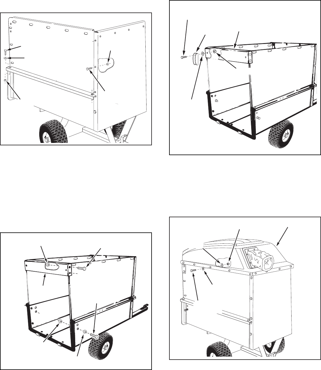
FIGURE 3
FIGURE 1
This unit is shipped WITHOUT GASOLINE or OIL. After
assembly, see separate engine manual for proper fuel
and engine oil recommendations.
CAUTION: Do not leave the cart unattended
in upright position during assembly. A falling
cartcancausepersonalinjury!Payclose
attention to the stability of the cart while it
remains in an upright position. For best stability,
assemble on a smooth level surface.
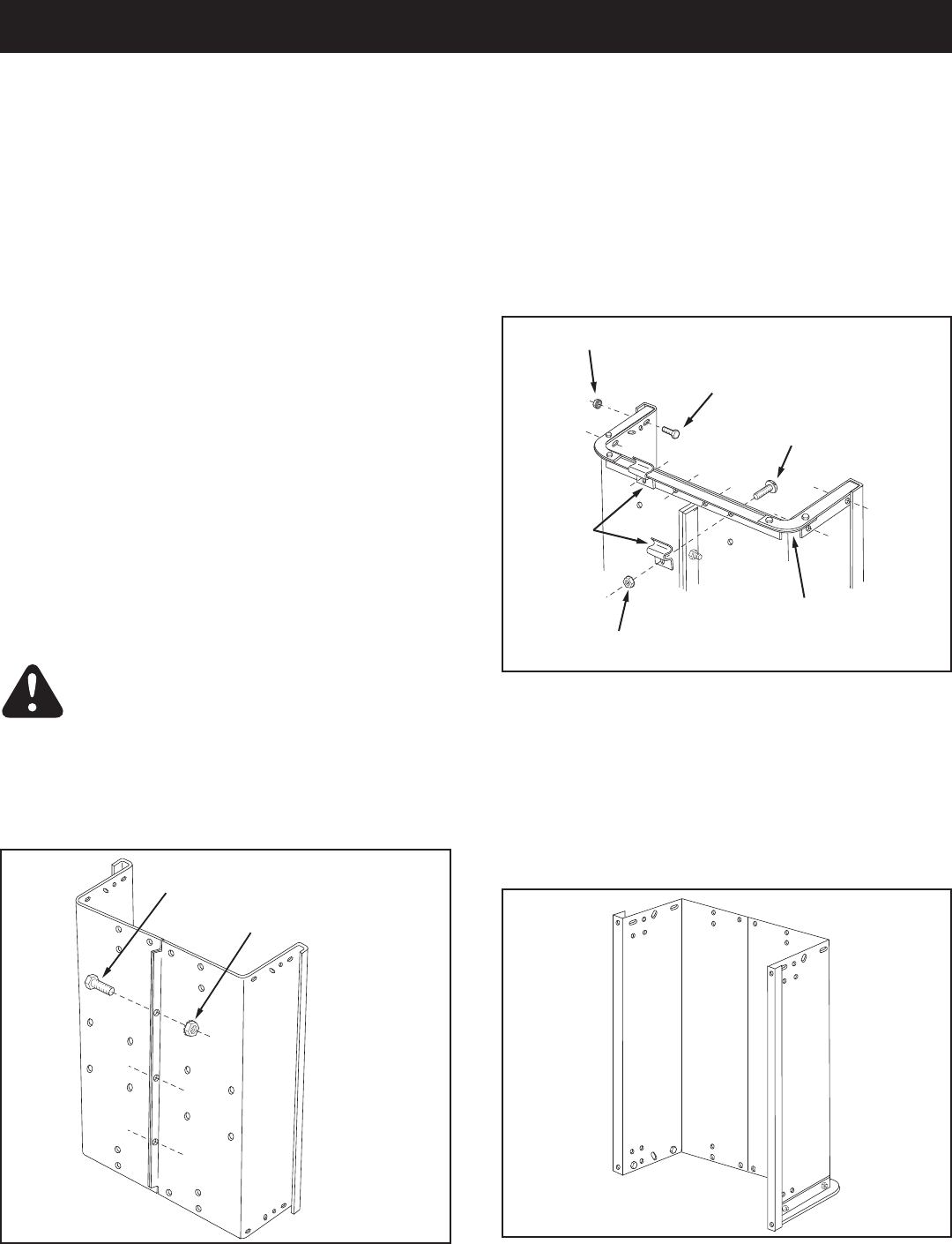
• Placecartbodyhalvesuprightonasmoothlevel
surfacesuchasagarageoororapaveddriveway.
Seegure1.
ASSEMBLING THE CART BODY
TOOLS REQUIRED FOR ASSEMBLY
(1) Screwdriver
(1) Pliers
(2)7/16"Wrenches
(2)1/2"Wrench
(2)9/16"Wrenches
(2)3/4"Wrenches(onlyifgure23onpage12isused)
FIGURE 2
REMOVAL OF PARTS FROM CARTONS
• Removethehardwarepacksandallloosepartsfrom
the cartons.
• Layoutandidentifypartsshownincartoncontents.
• Layoutandidentifypartsinthehardwarepacks.Keep
contents of each hardware package separate.
1/4" x 5/8" HEX BOLT
1/4" NYLOCK NUT
• Assemblecartbodyhalvestogetherusingthree1/4"x
5/8"hexboltsand1/4"nylocknutsasshowningure
1. Do not tighten yet.
5/16" NYLOCK NUT
1/4" NYLOCK NUT
1/4" x 5/8"
HEX BOLT
5/16" x 3/4" TRUSS
HEAD BOLT
DOOR
SUPPORT
TAILGATE
REINFORCEMENT
BRACKET
• Fitthetailgatereinforcementbracketovertheendof
the cart bed. Position the two door support brackets
on the bottom of the reinforcement bracket as shown
ingure2.Fastenthereinforcementbracketandthe
door supports to the bottom of the cart using four
5/16"x3/4"trussheadboltsand5/16"nylocknuts.
Do not tighten yet. Seegure2.
• Fastenthetailgatereinforcementbrackettothesides
ofthecartbodyusingfour1/4"x5/8"hexboltsand
1/4"nylocknutsasshowningure2.Do not tighten
yet.
• Pull the cart body halves together.
Tightenthefourtrussheadboltsingure2.
Tighten thefourhexboltsingure2.
Tightenthethreehexboltsingure1,keepingthe
bottom aligned and pulled together.
• Carefullyipthecartendforendsothatitrestson
thetailgatereinforcementbracket.Seegure3.
9
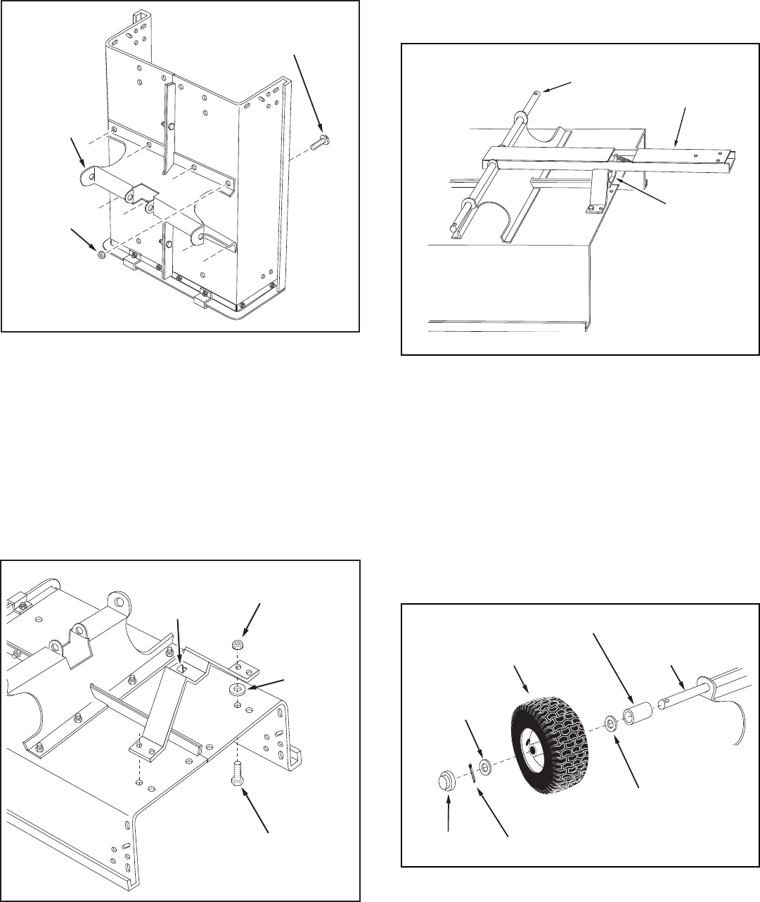
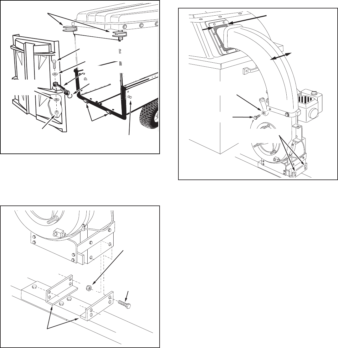
FIGURE 4
• Topreventaccidentaltippingduringthefollowing
assembly procedures, lower the cart to rest upside
down, with the wheel support facing up, as shown in
gure5.
• Alignthelatchstandbracketsothatthetabisatthe
rear. Fasten the bracket to the rear set of holes at the
frontofthecartusingtwo1/4"x5/8"hexbolts,1/4"
atwashersand1/4"nylocknuts.Usethe1/4"at
washers as shims between the bracket and the cart
bed. Makengertight.Seegure5.
FIGURE 6
FIGURE 7
• Positionthereartongueonthewheelsupportandthe
latch stand bracket. Assemble the axle through the
wheel support and the tongue. Seegure6.
IMPORTANT: Make sure the tongue is securely locked
to the latch stand bracket by the latch lock lever.
• Assemblethewheelsupporttothebottomofthecart
usingeight5/16"x3/4"trussheadboltsand5/16"
nylocknutsasshowningure4.Headsofboltsgoon
the inside of cart. Tighten.
AXLE TONGUE
(REAR)
LATCH
LOCK
LEVER
COTTER PIN
WHEEL
HUB CAP
1" FLAT
WASHER
1" FLAT
WASHER
AXLE
SPACER TUBE
FIGURE 5
5/16"
NYLOCK
NUT
WHEEL
SUPPORT
5/16" x 3/4"
TRUSS HEAD BOLT
LATCH STAND
BRACKET
(Tab at rear)
1/4" x 5/8"
HEX BOLT
1/4" NYLOCK NUT
1/4" FLAT
WASHER
• Assembleaspacertube,a1"atwasher,awheel
(valvestemfacingout),andanother1"atwasher
ontotheaxleasshowningure7.Securethewheel
with a cotter pin, spreading the ends so that a hub
capcantoverthepin.Assemblethehubcapby
pressingitontotheatwasher.Repeatonotherend
of axle.
• Pumpgreaseintogreasettingsonwheelsuntil
grease is forced out through ends of hubs.
10
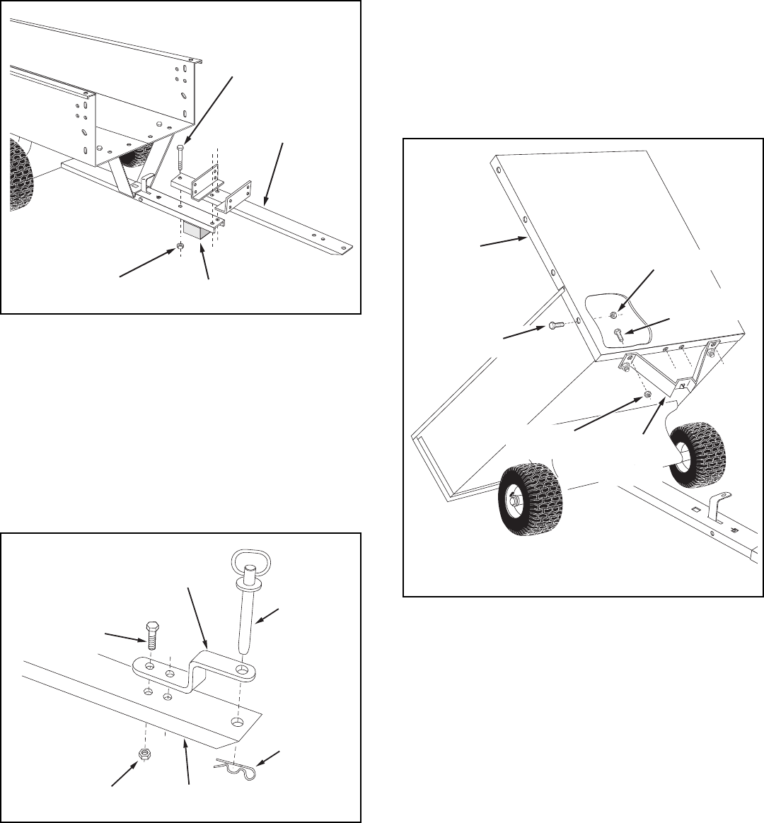
FIGURE 8
• Flipthecartoversothatitrestsonitswheels.
• Assemblethefronttongueontopofthereartongue
usingthree3/8"x3"hexboltsand3/8"nylocknuts.
Seegure8.
HINT: For easier assembly, support the rear tongue with
a block of wood.
• Assemblethehitchbrackettothefronttongueusing
two3/8"x1-1/4"hexboltsand3/8"nylocknuts.
Tighten.Seegure9.
• Securethehitchpintothehitchbracketandtongue
withthehaircotterpin.Seegure9.
FIGURE 10
FIGURE 9
• Releasethelatchlockleverandtiltthecartbedback.
Seegure10.
• Assemblethefrontpaneltothecartbed,sliding
the bottom lip of the panel in between the cart bed
and the latch stand bracket. Fasten the panel to the
bottomandsidesofthecartbedusingsix1/4"x5/8"
hexboltsand1/4"nylocknuts.Tighten.Seegure10.
• Tighten the two bolts that you assembled to the latch
standbracketingure5.
TONGUE
(FRONT)
3/8" x 3"
HEX BOLT
BLOCK
3/8" NYLOCK NUT
ASSEMBLING VAC PARTS
1/4" x 5/8"
HEX BOLT
FRONT
PANEL
1/4" NYLOCK NUT
1/4" x 5/8"
HEX BOLT
1/4" NYLOCK NUT
LATCH
STAND
BRACKET
HITCH BRACKET
3/8" x 1-1/4"
HEX BOLT
3/8" NYLOCK NUT TONGUE
HITCH
PIN
HAIR
COTTER
PIN
11
FIGURE 11
• Placeasidepanelontopofthecartbedange,
inside the lip of the front panel. Fasten the side panel
tothefrontpanelusingthree1/4"x5/8"hexbolts
and1/4"nylocknuts.Fastenthesidepaneltothecart
bedangeusingtwo1/4"x5/8"hexbolts,1/4"at
washersand1/4"nylocknuts.Tighten. Seegure11.
Repeat on other side.
FIGURE 12
• Screwa1/4"nylocknutontoa1/4"x1"hexboltuntil
itisabout1/4"fromthebolthead.Inserttheboltinto
theholeshowninthesideofthecartingure12.
Fastenthebolttothecartusinga1/4"nylocknut.
Tighten so that the nut is one or two threads past the
end of the bolt. Repeat on the other side.
• Assemblethecrossbracetothetoprearholesinthe
sidepanelsusingfour1/4"x5/8"hexboltsand1/4"
nylocknuts.Seegure12.
• Assembleadoorlatchateachendofthecrossbrace
usinga5/16"x3/4"hexbolt,anylonwasheranda
5/16"nylocknut.Placethenylonwasherbetweenthe
door latch and cross brace. Tighten so that latch is
snugbutwillstillrotate.Seegure13.
FIGURE 13
• Installthepolyhardtopusingfourteen1/4"x3/4"
hexboltsand1/4"atwashersontheoutsideand
fourteen1/4"atwashersand1/4"nylocknutsonthe
inside. Tighten.Seegure14.
FIGURE 14
1/4" x 5/8"
HEX BOLT
1/4" FLAT
WASHER
1/4" NYLOCK NUT
1/4" NYLOCK NUT
1/4" x 5/8"
HEX BOLT
5/16" x 3/4"
HEX BOLT
CROSS
BRACE
DOOR
LATCH
NYLON
WASHER
5/16" NYLOCK NUT
1/4" NYLOCK NUT
1/4" NYLOCK NUT
1/4" x 5/8"
HEX BOLT
CROSS
BRACE
1/4" NYLOCK NUT
1/4" x 1"
HEX BOLT 1/4" x 3/4"
HEX BOLT
1/4" FLAT
WASHER
1/4" NYLOCK NUT POLY HARD TOP
1/4" FLAT
WASHER
12
• Assembleashorttarpstraptoreardoorusingone
1/4"x1-1/4"hexbolt,two1/4"atwashersandone
1/4"nylocknut.Assemblean"S"hookthroughloose
endofstrap.Seegure15.Repeatonothersideof
door.
• Assembledoortorearofcartbyrestingbottomof
door on door supports and pushing top of door in
against cross brace. Secure top of door using door
latchesoneachside.Seegure15.
• Hookboththetarpstrapsontothe1/4"x1"hexbolts
inthesidesofthecart.Seegure15.
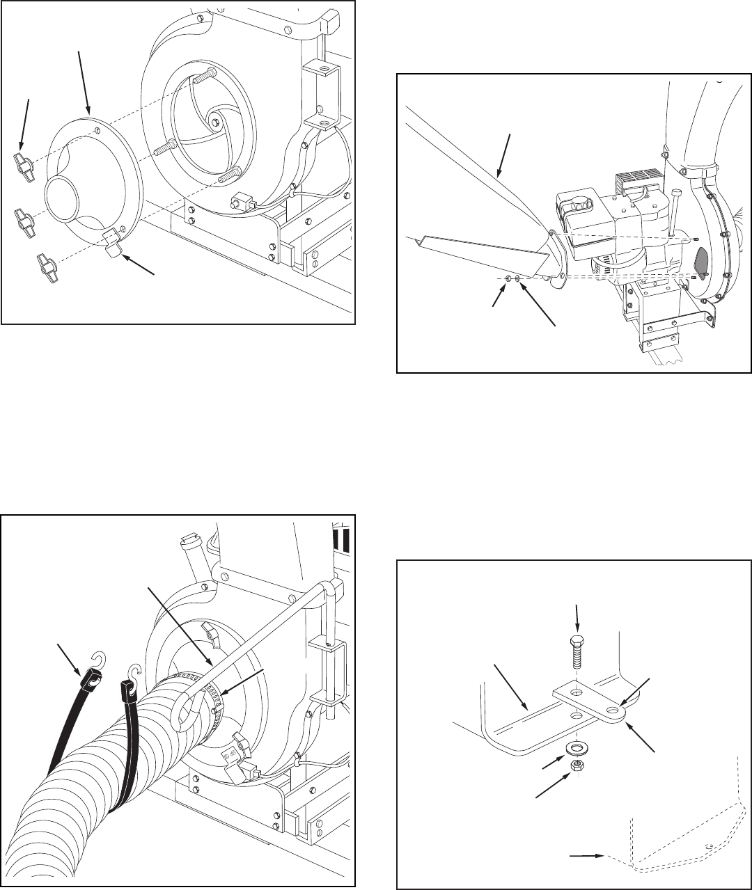
• Attachtheengine/impellerhousingassemblytothe
upper holes in the angles welded to the tongue. Use
four5/16"x3/4"hexboltsand5/16"nylocknuts.
Tighten.Seegure16.
FIGURE 16
FIGURE 15
5/16"
NYLOCK
NUT
5/16" x 3/4"
HEX BOLT
WELDED
ANGLES
FRONT
TONGUE
FIGURE 17
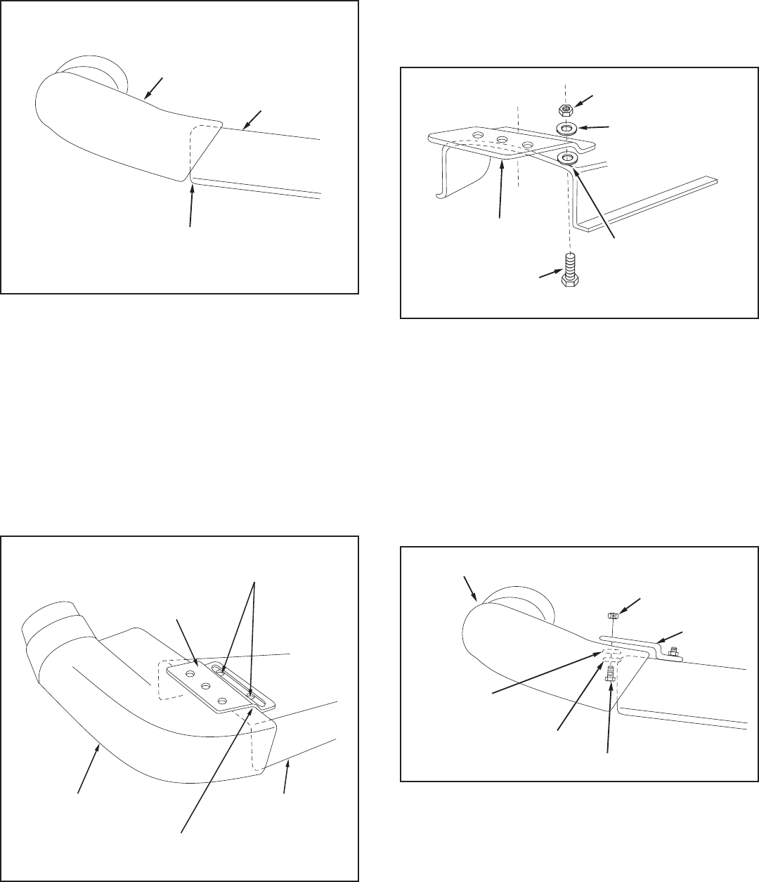
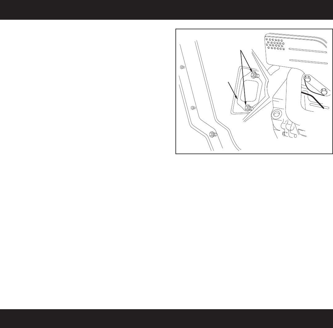
• Assembletheelbowtotheimpellerhousingusingfour
5/16"x3/4"threadforminghexboltsandfournylon
washers. Push while turning to help start the bolts into
the un-threaded holes. Tighten.Seegure17.
• Tocentertheelbowwiththeopeninginthehardtop:
a. Push the vinyl boot back inside the opening.
b. Loosen by approximately 1/4 turn each, the four
boltsthatyouassembledingure17.
c. Push against the elbow to center it with the sides
of the opening.
d. Retighten the four bolts that you loosened.
• Pullthevinylbootontotheendoftheelbow.
Center elbow between
sides of opening
Loosen (4) bolts
1/4 turn each
5/16" x 3/4"
HEX BOLT
(Thread Forming)
NYLON
WASHER
1/4" x 1-1/4" HEX BOLT
1/4" FLAT WASHER
1/4" NYLOCK NUT
TARP STRAP (SHORT)
DOOR
SUPPORTS
DOOR LATCH
1/4" FLAT
WASHER
"S" HOOK
1/4" x 1"
HEX BOLT
13
• Assemblethehoseadapter(nozzle)tothefrontof
the impeller housing and secure with the three knobs.
Make sure that the switch actuator bracket contacts
theswitchonthehousing.Seegure18.
FIGURE 21
FIGURE 19
• Placeahoseclampontooneendofhose.Pushhose
ontohoseadapter(nozzle).Tightenhoseclamponto
hose and hose adapter. Do not collapse hose adapter
whentighteningclamp.Seegure19
• Placethehosehangerrodintothehosehangerbracket
ontheimpellerhousingassembly.Seegure19.
• Loopthe25"tarpstrapunderthehose.Hooktothe
hosehangerrod.Seegure19.
FIGURE 18
HOSE ADAPTER
(NOZZLE)
KNOB
SWITCH
ACTUATOR
BRACKET
• Assemblethehitchplatetothetractorhitchif:
a. Your tractor has a square (straight) hitch frame,
to help prevent binding.
b. Your tractor has a lightweight hitch frame that
needs reinforcing for towing the Chip-N-Vac.
Usea1/2"x1-1/4"hexbolt,a7/16"atwasheranda
1/2"nylocknut.Seegure21.
TRACTOR
HITCH FRAME
(SQUARE)
HITCH
PLATE
TRACTOR
HITCH FRAME
(TAPERED)
1/2" x 1-1/4"
HEX BOLT
7/16" FLAT WASHER
1/2" NYLOCK NUT
ATTACH
MOW-N-VAC
HERE
FIGURE 20
5/16" FLAT
WASHER
CHIPPER CHUTE
ASSEMBLY
5/16"
NYLOCK
NUT
25" TARP
STRAP
HOSE HANGER ROD
HOSE
CLAMP
HINT: Tip the cart bed back for easier access in the next
paragraph.
•. Attachthechipperchuteassemblytotheweldbolts
on the back side of the impeller housing using three
5/16"atwashersand5/16"Nylocknuts.Tighten.
Seegure20.
• Insertthetamperplugintotheendofthechipper
chute assembly.
14
ASSEMBLINGTHEDECKADAPTER(#62468)
TOTHEMOWERDECK
Contents of Hardware Pack for Deck Adapter:
I J K
A B
D
C
H
F
G
NOT SHOWN FULL SIZE
E
• Identifyyourmowerdeck(seefoldouts)andcut
out the correct discharge opening template for your
mowerdecksize.Ifthereisnotemplateforyourdeck
sizeyoucanmakeyourowntemplatebymarking
around a piece of cardboard held against the edge of
the discharge opening.
• Tapethetemplatetothefaceoftheadapter,locating
templateapproximately1/2"fromfrontand1/4"down
fromtopofadapter.Keepasclosetotopaspossible.
Seegure23.Markoutlineoftemplateonfaceof
adapter using white crayon, nail or scriber. Drill a
starting hole inside the outline, then use a saber saw
orkeyholesawtocutouttheopening.Seegure23.
FIGURE 23
CAUTION: Mowerdeectormustbe
replaced when Chip-N-Vac deck adapter
is removed. Do Not operate mower
unlessadapterordeectorisinplaceand
properly mounted.
FIGURE 22- FULL SIZE
1/4" DOWN
Keep cut-off as close to
the top edge as possible.
IMPORTANT:
1/2" FROM FRONT
NOTE: Not all of the parts in the deck adapter hardware
packagewillbeneededforyourparticulartup.
BEFOREPROCEEDING,look in the fold-out sheets included with this manual
tondtemplatesforSearsmowerdecks.Ifwritteninstructionsareprintedonthe
template, follow those instructions instead of the instructions in this manual.
STOP
• Removethemowerdischargedeectorfromyour
mowerdeck.Savethedeectorandhardwarefor
remountingdeector.
REF. PART NO. QTY. DESCRIPTION
A 43840 2 HexBolt,5/16"x1-1/4"
B 43661 4 HexBolt,1/4"x1"
C 43080 2 CarriageBolt,5/16"x3/4"
D 47810 3 NylockNut,5/16"
E 47189 5 NylockNut,1/4"
F 43088 9 FlatSteelWasher,1/4"Std.
G 43081 12 FlatWasher,5/16"Std.
H 1543-69 5 Nylon Washer
I 23825 1 Mounting Strap
J 23826 1 Angle Bracket
K23827 1 Mounting Bracket
15
FIGURE 24
• Holdingtheadapterbracketandthedeckadapter
together, position the deck adapter on the mower
deck.Keepingtheedgeofdeckadapterascloseas
possible to the offset in the adapter bracket, see if the
slot in the adapter bracket can be aligned with one
ortwoofthedeectorholesinyourmowerdeck's
discharge opening. If the bracket can not be located
correctly using existing holes, it will be necessary to
drilloneortwo5/16"diameterholesinthedeck.See
gure25.
• Positiontheadapteroverthedeckopening,andcheck
fortofcutoutasshowningure24.Trimcutout,if
necessary,toallowtiltingofadapter,keepingthetas
close as possible for best vacuum suction.
• Assembletheadapterbrackettothedeckusingtwo
5/16"x1-1/4"hexbolts,5/16"atwashersand5/16"
nylocknuts.Seegure26.
NOTE:Itmaybenecessarytouseextra5/16"at
washers to shim under the bracket next to the deck
surface. Ten extra washers have been furnished as
shims.Seegure26.
FIGURE 26
FIGURE 27
• Assembleendofhoseandahoseclampoverthe
round opening of deck adapter and tighten clamp. GO
DIRECTLY TO THE OPERATION INSTRUCTIONS
ON PAGE 16.
•. Withdeckadapterpositionedcorrectlyoverthe
discharge opening, use the adapter bracket as a
templateanddrillthree9/32"diameterholesinthetop
ofthedeckadapter.Seegure27.
• Boltdeckadaptertobracketusingthree1/4"x1"
bolts,nylonwashers,1/4"atwashersand1/4"lock
nuts. Nylon washers should be against the inside of
thedeckadapter.Seegure27.
FIGURE 25
MOWER DECK
DECK ADAPTER
NOTE: Make sure adapter clears gauge
wheels on mower deck
Curl on deck may be located outside of
adapter or inside depending on deck
opening design
DECK ADAPTER MOWER DECK
ADAPTER BRACKET
Keep edge of adapter as close
as possible to offset in bracket
Use existing holes or drill 5/16"
diameter hole or holes.
ADAPTER BRACKET
5/16" flat washers
used as needed for
shims to adjust for
variations in decks.
(2) 5/16" NYLOCK NUTS
5/16" x 1-1/4"
HEX BOLT
(2) 5/16" FLAT
WASHERS
(3) 1/4" NYLOCK
NUTS
(3) NYLON
WASHERS
(3) 1/4" STEEL WASHERS
(3) 1/4" x 1" HEX BOLTS
ADAPTER
BRACKET
MOWER DECK
DECK ADAPTER
16
FIGURE 28
• Aftercartisemptied,securecarttotonguewithlatch
and reattach the rear door and the vinyl boot.
HOW TO USE YOUR CHIP-N-VAC
BEFORE STARTING
• YourChip-N-Vacengineisshippedwithoutoilor
gasoline. Service the Chip-N-Vac engine with oil and
gas as instructed in the separate engine manual.
• InspecttheChip-N-Vactomakesureallcovers(rear
door, vinyl boot, elbow, hose adapter, hose and deck
adapter are properly attached.
• Checktiresforproperination(12-14lbs).
WARNING: Neverllfueltankindoors,or
with the engine running, or while the engine
ishot.Donotsmokewhilellingtank.
HOW TO STOP YOUR CHIP-N-VAC
• Tostopengine,movethethrottlecontrollevertothe
OFF position.
• Disconnectsparkplugwirefromplugtopreventac-
cidental starting while equipment is unattended or is
being worked on.
CAUTION: Themuferandadjacent
areas are hot!
HOW TO START YOUR CHIP-N-VAC
OPERATION
• CheckoilandgasinChip-N-Vacengine.
• Attachsparkplugwiretosparkplug.
• MovechokeleveronenginetoCHOKEposition.
(A warm engine may not require choking.)
• MovethrottlecontrolleveronenginetoFASTposition.
• Graspstarterhandleandpullropeoutslowlyuntil
engine reaches start of compression cycle (rope will
pull slightly harder at this point). Let the rope rewind
slowly.
• Pullropewitharapid,continuous,fullarmstroke.
Keeparmgriponstarterhandle.Letroperewind
slowly. Do not let starter handle snap back against
starter.
• Repeatinstructionsintwoprecedingparagraphsuntil
engineres.Whenenginestarts,movechokecontrol
gradually to RUN position.
WARNING: Never start or run the engine
without all covers being properly attached to
the blower housing and cart.
CAUTION: Vehicle braking and stability
may be affected with the addition of an
accessory or an attachment. Be aware of
changing conditions on slopes.
• InspecttheChip-N-Vactomakesureallcovers(rear
door, vinyl boot, elbow, chipper chute with tamper
plug,hoseadapter(nozzle),hoseanddeckadapter
are properly attached.
• Checktiresforproperination(12-14lbs).
• CheckoilandgasinChip-N-Vacengine.
• Beginoperationatlowspeed,adjustingforwardspeed
to match grass height and/or moisture condition to
prevent clogging.
• Donotattempttovacuumupanymaterialother
than vegetation found in a normal yard, such as light
branches, leaves, twigs, etc.
• Toemptycart,shutofftractorengineandsetbrake.
• ShutoffChip-N-Vacengine.
• Removereardoorfromcart.
• Releasethelatchholdingcartdowntothetongueby
pullinguponthelatchlever.Seegure28.
• Usingarakeorsuitabletool,pullthegrassclippings
and/or leaves out of cart.
WARNING: Should your Chip-N-Vac
become clogged, shut off tractor and
Chip-N-Vac engines. Before attempting
to unclog, remove wire from spark plug to
prevent accidental starting.
CAUTION: Toavoidpossibleinjury,be
sure that no one is near the cart before
releasing the latch.
17
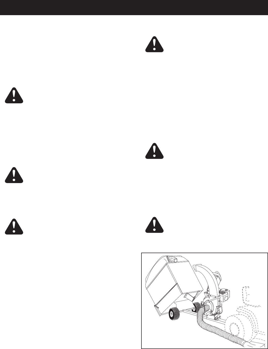
USING THE CHIPPER CHUTE
• Materialsuchasstalksorheavybranchesupto3"in
diameter may be fed into the chipper chute as shown
ingure29.
• Besuretoweareyeprotectionandgloveswhen
feeding material into the chipper chute.
• Usethetamperplug,notyourhands,toforcematerial
down through the chipper chute.
• Forbestperformance,itisimportanttokeepthe
chipper blades sharp. If the composition of the
material being discharged changes (becomes
stringy, etc.) or if the rate of discharge slows down
considerably, it is likely that the chipper blades are dull
and need to be sharpened or replaced. Refer to the
ServiceandAdjustmentssection,onpage29.
WARNING: Do not attempt to feed any
materiallargerthan3"indiameterintothe
chipperchute.Personalinjuryordamageto
the machine could result.
DANGER:Keephandsout of chipper
chute. Rotating blades in impeller housing can
causeseriousinjury.Usethetamperplugto
help push material down into the chute.
FIGURE 29
18
MAINTENANCE
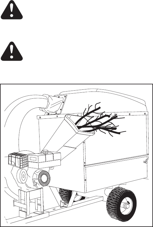
Service Dates
Check for loose fasteners X
Check soft vinyl boot X
Check tire pressure X
Check engine oil level X
Lubricate X
Clean X X
Maintain engine per instructions below and in engine manual.
Before each use
After each use
Every season
Before storage
CUSTOMER RESPONSIBILITIES
• Readandfollowthemaintenancescheduleandthemaintenanceprocedureslistedinthissection.
MAINTENANCE SCHEDULE
Fill in dates as you
complete regular service.
BEFORE EACH USE
CHECKFORLOOSEFASTENERS
• Make a thorough visual check of the Chip-N- Vac
for any bolts and nuts which may have loosened.
Retighten any loose bolts and nuts.
CHECKVINYLBOOT
• Checkthesoftvinylboot(onfrontofhardtop)for
wear. Replace if worn or damaged.
CHECKTIREPRESSURE
• Checktirepressureregularly.Recommendedtire
pressure is 12-14 Lbs.
CHECKENGINEOILLEVEL
• Checkoillevelbeforeeachuse.Maintainengineoilas
instructed in the separate engine manual.
LUBRICATION
• At the beginning of each season, lubricate the latch,
latch pivot bolt, and the axle where the hitch tongue
pivots, with a light machine oil.
• Atleastonceaseason,greaseoroilthewheel
bearings. Use automotive wheel bearing type grease
or 20 weight oil.
WARNING: Always stop engine and
disconnect spark plug wire before cleaning,
lubricating or before performing any repairs
or maintenance.
ENGINE MAINTENANCE
• Checkoil level before each use. Maintain engine oil
as instructed in the separate engine manual.
• Serviceair cleaner every 25 hours under normal
conditions. Clean every few hours under extremely
dusty conditions. Poor engine performance and
oodingusuallyindicatesthattheaircleanershould
be serviced. To service the air cleaner, refer to the
separate engine manual.
• Thespark plug should be cleaned and the gap
reset once a season. Spark plug replacement is
recommended at the start of each season. Check
the engine manual for correct plug type and gap
specications.
CLEANING
• Makesurethecart,thesideandfrontpanelsand
top are cleaned after each use. Grass clippings and
leaves left in the cart will mildew and cause damage if
not cleaned out.
• Clean the engine regularly with a cloth or brush.
Keepthecoolingnsontheenginehousingclean
to permit proper air circulation which is essential to
engine performance and life. Be sure to remove all dirt
anddebrisfrommuferarea.
19
STORAGE
• Ifstoringinanunventilatedormetalstorageshed,coat
metal parts with light oil or silicone to prevent rust.
• Storeunitinaclean,dryarea.
• Cleantheengineandtheentireunitthoroughly.
• Refertoenginemanualforcorrectenginestorage
instructions.
SERVICE AND ADJUSTMENTS
FIGURE 30
SHARPENING OR REPLACING CHIPPER
BLADES
• Disconnectthesparkplugwireandmovewireaway
from the spark plug.
• Removetheaccessplatebyremovingtwohexlock
nuts.Seegure30.
• Locateoneofthechipperbladesintheaccessplate
opening by rotating the impeller assembly by hand.
Removethebladeusinga3/16"allenwrenchon
theoutsideofthebladeanda1/2"wrenchonthe
impeller assembly, inside the housing.
• Removetheotherbladeinthesamemanner.
• Replaceorsharpenblades.Ifsharpening,make
certain to remove an equal amount from each blade.
Reassemble in reverse order.
NOTE: Make certain the blades are reassembled with
the sharp edge facing upward, as viewed from the access
plate opening.
NYLOCK NUTS
ACCESS
PLATE

20
TROUBLESHOOTING
PROBLEM POSSIBLE CAUSE(S) CORRECTIVE ACTION
Engine fails to start 1. Spark plug wire disconnected. 1. Connect wire to spark plug.
2.Safetyswitchnotcontacted. 2.Correctlyinstallhoseadapternozzle.
3. Fuel tank empty, or stale fuel. 3. Fill tank with clean, fresh fuel.
4. Fuel shut-off valve closed 4. Open fuel shut-off valve.
(if so equipped).
5.Faultysparkplug. 5.Clean,adjustgaporreplace.
Loss of power; 1. Spark plug wire loose 1. Connect and tighten spark plug wire.
operationerratic. 2.UnitrunningonCHOKE. 2.MovechokelevertoOFFposition.
3.Blockedfuellineorstalefuel. 3.Cleanfuelline;lltankwithclean
fresh gasoline.
4. Water or dirt in fuel system. 4. Disconnect fuel line at carburetor to drain
fueltank.Rellwithfreshfuel.
5.Carburetoroutofadjustment. 5.Adjustcarburetor.*
6.Dirtyaircleaner. 6.Serviceaircleaner.*
Engineoverheats 1.Carburetornotadjusted 1.Adjustcarburetor.*
properly.
2. Engine oil level low. 2. Fill crankcase with proper oil.
Too much vibration Loose parts or damaged Stop engine immediately and disconnect
impeller. spark plug wire. Tighten all bolts and nuts.
Make all necessary repairs. If vibration
continues, have unit serviced by an
authorizedservicedealer.
Unit does not 1. Discharge chute (elbow) 1. Stop engine immediately and disconnect
discharge clogged. spark plug wire. Clean inside of housing
and discharge chute (elbow).
2.Foreignobjectlodgedin 2.Stopengineimmediatelyanddisconnect
impeller. sparkplugwire.Removelodgedobject.
3. Chip-N-Vac cart is full. 3. Empty cart.
Rate of discharge Chipper blades dull. Sharpen or replace chipper blades.
when chipping
slows considerably,
or composition of
discharged material
changes.
*Refertotheenginemanualpackedwithyourunit.
NOTE:Forrepairsbeyondtheminoradjustmentslistedabove,pleasecontactyournearestauthorizedservicedealer.

21
NOTES

22
NOTES
23
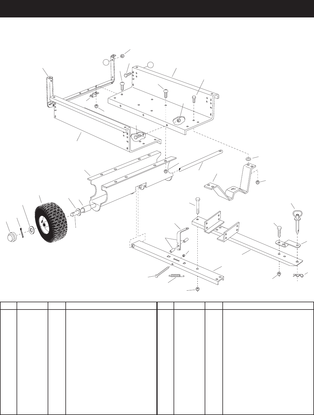
PARTS
REF. PART NO. QTY. DESCRIPTION
1 23985 2 Cart Body
2 62458 1 Tailgate Reinforcement Bracket
3 23507 1 Wheel Support
4 24497 1 Latch Stand Bracket
5 24897 1 Axle,Wheel1"Dia.
6 42159 2 Wheel w/Tire, 15 x 6.00
7 43093 2 CotterPin,1/8"Dia.x1-1/2"
8 43601 4 Washer,Flat1"
9 44678 2 SpacerTube,1-1/4"x2"Lg.
10 43014 2 Hub Cap
11 43866 9 HexBolt,1/4-20x5/8"
12 47189 9 Nylock Nut, 1/4-20
13 43814 12 TrussHd.Bolt,5/16-18x3/4"
14 41076 2 Spacer
REF. PART NO. QTY. DESCRIPTION
15 43088 2 Washer,Flat1/4"
16 63917 1 TongueWeldmentAss'y.(Rear)
17 63155 1 TongueWeldmentAss'y.(Front)
18 24614 1 Latch Lock Lever
19 23475 1 Hitch Bracket
20 43884 1 Hitch Pin
21 43343 1 Pin,HairCotter1/8"
22 43087 2 HexBolt,3/8-16x1-1/4"
23 23838 2 Door Support
24 HA21362 5 Nylock Nut, 3/8-16
25 47407 1 HexBolt,5/16-18x3-3/4"
26 47408 1 Spring, Extension
27 43574 3 HexBolt,3/8-16x3"
28 47810 13 Nylock Nut, 5/16-18
11
11
4
1
2
11
1
3
5
A
5
8
6
8
7
10
9
12
12
12
13
13
28
28
15
16
17
18
19
20
21
22
24
25
26
27
28
23
A
24
14
REPAIR PARTS FOR MODEL 486.25013 CHIP-N-VAC
IMPELLER HOUSING ASSEMBLY
24
42
43
32
41
TO
TRACTOR
26
24
25
27
23
4 39 40
8
12
35
13
21
20
28
33
13
33
35
34 13
13
13
36
35
31
35
13
1 2
2
3
4
4
6
8
8
8
9
14
16
17
19
19
18
29
30
40
10
11
50
A
A
22
20 35
B
B
4
13
5
8
13
8
13
13
8
40
40
40
40
40
35
35
35
35
44
44
44
34
34
34
47
45
4647
48
37
49
13
51
15
12
12
13
13
52,53,54,55
7
38
35
35
44
8
8
ADAPTER #62468
31 30
36
35
35
13
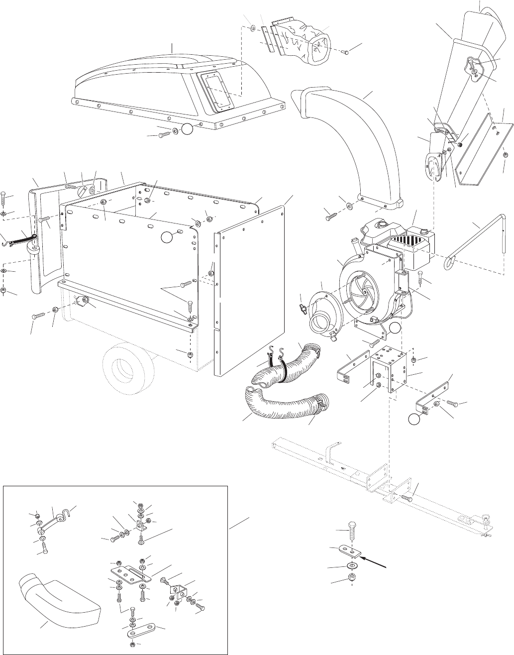
REPAIR PARTS FOR MODEL 486.25013 CHIP-N-VAC
IMPELLER HOUSING ASSEMBLY

25
REF. PART NO. QTY. DESCRIPTION
1 24080 1 Engine Base
2 24078 2 Brace, Housing
3 24958 1 Hose Hanger Bracket
4 43182 14 Bolt,Hex5/16-18x3/4"
5 43840 2 Bolt,Hex5/16-18x1-1/4"
6 43085 4 Bolt,Hex5/16-18x1-1/2"
7 731-1617 1 Tamper, Plug
8 47810 24 Nut, Nylock 5/16-18
9 43791 1 HoseAdapter(Nozzle)
10 47630 4 Screw,SelfTap5/16-18x3/4"
11 712-0421 3 Knob(SeeItem#8,Page24)
12 43012 19 Bolt,Hex1/4-20x3/4"
13 47189 48 Nut, Nylock 1/4-20 Thd.
14 42462 1 Engine
15 681-0068 1 Chute Assembly
16 49974 1 Hose Hanger Rod
17 46420 1 Elbow
18 41882 1 Hose(6"x84")
19 43793 2 HoseClamp6"
20 24678 2 Side Panel Cart Extension
21 24679 1 Front Panel Cart Extension
22 23836 1 Cross Brace
23 64244 1 Hard Top Assembly
(Includes 24,25,26,27)
24 43882 4 Rivet,3/16"
25 43910 4 Washer,Flat3/16"
26 24798 4 Boot Mounting Strap
27 48133 1 Vinyl Boot (Hardtop)
28 44790 1 Poly Rear Door
29 43790 1 Strap,Tarp25"
REF. PART NO. QTY. DESCRIPTION
30 44849 4 "S"Hook,#32
31 44850 4 Strap, Tarp (Less Hooks)
32 23540 1 Hitch Plate
33 43866 20 Bolt,Hex1/4-20x5/8"
34 43661 6 Bolt,Hex1/4-20x1"
35 43088 47 Washer,1/4"STD
36 1509-90 5 Bolt,Hex1/4-20x1-1/4"
37 23827 1 Mounting Bracket
38 24098 1 Bracket, Chute Reinforcement
39 23789 2 Door Latch
40 1543-69 9 Washer,Nylon21/64"
41 43351 1 Bolt,Hex1/2-13x1-1/4"
42 712-3083 1 Nut, Nylock 1/2-13
43 43352 1 Washer,Flat7/16"
44 43081 15 Washer,5/16"STD
45 43830 1 Adapter, Deck
46 23560 1 Bracket, Deck Adapter
47 43080 2 Bolt,Carr.5/16"x3/4"
48 23825 1 Mounting Strap
49 23826 1 Angle Bracket
50 1 Impeller Housing Assembly
(See page 26)
51 62468 1 DeckAdapterKit(Includes parts
in box on page 24)
52 63376 1 Chipper Chute Assembly (Upper)
53 735-0249 1 Flap, Chute (Included in item 52)
54 781-0633 1 Strap, Flap (Included in item 52)
55 728-3001 3 Rivet,Pop5/32"
42486 3 Owner'sManual
REPAIR PARTS FOR MODEL 486.25013 CHIP-N-VAC
IMPELLER HOUSING ASSEMBLY
26
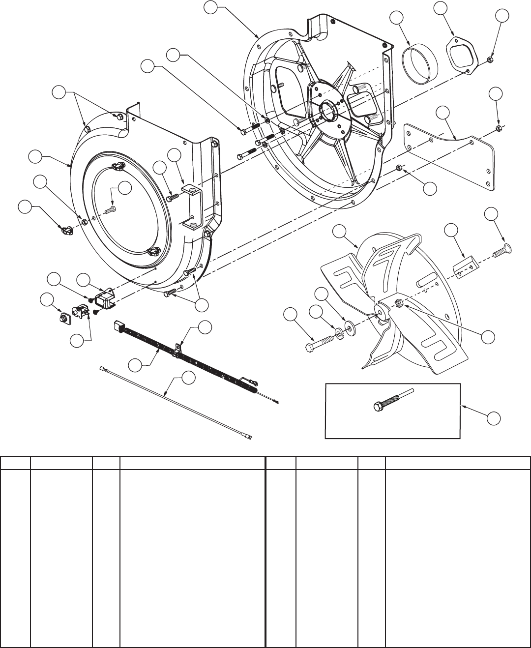
REPAIR PARTS FOR MODEL 486.25013 CHIP-N-VAC
IMPELLER HOUSING ASSEMBLY
REF. PART NO. QTY. DESCRIPTION
1 629-0241A 1 Harness, Wire
2 63993 1 HousingAss'y.Inner
3 24633 1 HousingAss'y.Outer
4 43182 12 Bolt,Hex5/16-18x3/4"
5 710-0772 4 Bolt,Hex5/16-24x2"
6 710-1268 2 Screw,SelfTap#10-16x3/8"
7 43063 3 Bolt,Hex5/16-18x1"
8 712-0421 3 Knob
9 47810 14 Nut, Hex Nylock 5/16-18
10 43086 4 Washer,Lock5/16"SpringType
11 719-0330B 1 Adapter, Mounting
12 725-1700 1 Cover, Switch
13 725-3166 1 Snap Mount Switch
14 726-0272 1 Clamp
REF. PART NO. QTY. DESCRIPTION
15 731-1613 1 Cover, Switch
16 24958 1 Hose Hanger Bracket
17 46584 3 HexNut,Whizlock5/16-18Thd.
18 24606 1 Spacer, Housing
19 736-0247 1 FlatWasher,13/32"x1-1/4"
20 66791 1 Impeller Assembly
21 710-1273 1 Bolt,Hex3/8-24x2-3/4"
22 43003 1 Lockwasher,3/8"
23 629-0923 1 Harness Adapter
24 44738 4 Nut,HexLock5/16-24"Unitork"
25 710-1054 4 Screw,FlatHd.5/16-24x1"
26 742-0544 2 Blade, Chipper
27 781-0627 1 Cover, Chipper
28 42294 1 Impeller Service Tool
2
6
18
10
5
2
3
5
10
8
24
4
3
17
8
4
7
16
23
11
9
18
22
4
9
21
16
23
15
1
16
13
14
1
15
6
12 19
27 9
26
25
For removing impeller assembly.
Must be ordered separately.
28
24
20
27
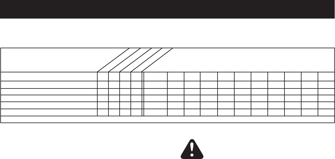
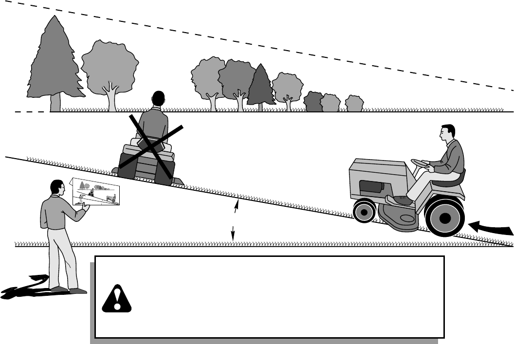
WARNING: To avoid serious injury, operate your tractor up and
down the face of slopes, never across the face. Do not operate
on slopes greater than 10 degrees. Make turns gradually to
prevent tipping or loss of control. Exercise extreme caution
when changing direction on slopes. Braking may be affected by
tractor attachment. Reduce speed on slopes.
1. Fold this page along dotted line indicated above.
2. Hold page before you so that its left edge is vertically parallel to a tree
trunk or other upright structure.
3. Sight across the fold in the direction of hill slope you want to measure.
4. Compare the angle of the fold with the slope of the hill.
ONLY RIDE UP AND DOWN HILL,
NOT ACROSS HILL
FO
L
D
A
LON
G
D
O
T
TED LI
N
E
T
H
IS
I
S
A
1
0
DEG
R
E
E
SL
O
P
E
10 DEGREES MAX.
SUGGESTED GUIDE FOR SIGHTING SLOPES FOR SAFE OPERATION
OF TRACTOR WITH ATTACHMENT

® Registered Trademark / TM Trademark of KCD IP, LLC in the United States, or Sears Brands, LLC in other countries
® Marca Registrada / TM Marca de Fábrica de KCD IP, LLC en Estados Unidos, o Sears Brands, LLC in otros países
Riding Equipment
questions or problems?
Satisfaction with your purchase
is our number one concern!
To troubleshoot problems,
get answers to questions, order parts,
or schedule repair service for your
Riding Equipment, call the number below.
Para respuestas a preguntas o problemas,
y ordenar piezas o pedir servicio para la
reparación de su equipo, llame el número abajo.
1-800-659-5917
Craftsman Help Line
www.craftsman.com
