Craftsman Dual Stage Snow Blower Tractor Attachment Owners Manual
2015-03-28
: Craftsman Craftsman-Dual-Stage-Snow-Blower-Tractor-Attachment-Owners-Manual-662064 craftsman-dual-stage-snow-blower-tractor-attachment-owners-manual-662064 craftsman pdf
Open the PDF directly: View PDF ![]() .
.
Page Count: 36
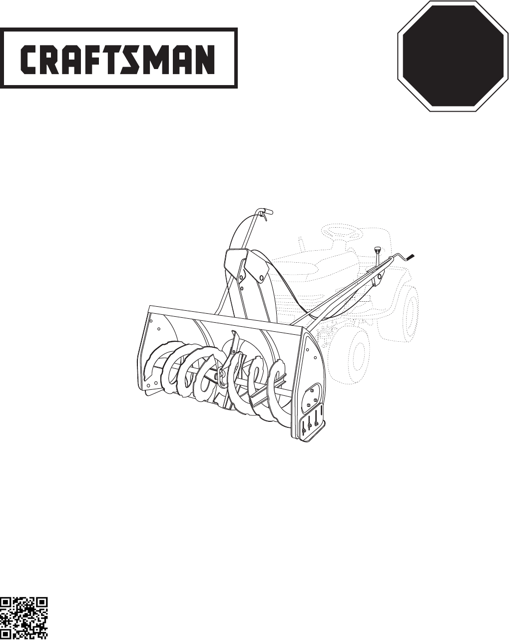
Operator's Manual
TRACTOR ATTACHMENT
Model No. 486.248373
42"- 2 STAGE SNOW THROWER
®
PRINTED IN U.S.A. FORM NO. 42975 (9/12/14)
CAUTION:
Before using this product, read
this manual and follow all Safety
Rules and Operating Instructions.
• Safety
• Assembly
• Operation
• Maintenance
• Parts
STOP
DO NOT RETURN TO STORE
For Missing Parts or Assembly
Questions Call 1-866-576-8388
FITS SERIES 917 CRAFTSMAN TRACTORS AND HUSQVARNA TRACTORS.
Want more information
or assembly tips?
Scan for Video
Instruction Guide.
Sears Brands Management Corporation, Hoffman Estates, IL 60179 U.S.A.
www.craftsman.com
2
TABLE OF CONTENTS
MODEL NUMBER: 486.248373
SERIAL NUMBER: __________________
DATE OF PURCHASE: __________________
Themodelnumberandserialnumberswillbefoundona
decal attached to the snow thrower.
Youshouldrecordboththeserialnumberandthedateof
purchase and keep in a safe place for future reference.
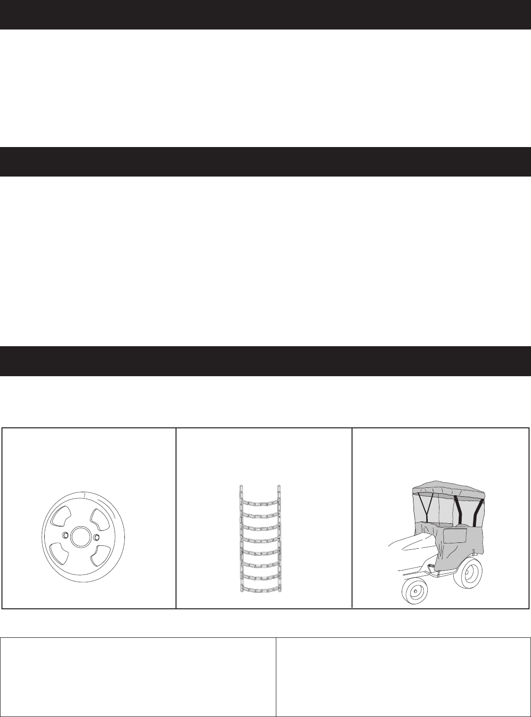
ACCESSORIES AND ATTACHMENTS
WHEEL WEIGHT
Theseandotheraccessoriesarerecommendedforusewithyourunit.Call1-888-331-4569tondoutiftheyareavailable.
Ifavailable,theymaybepurchasedatmostCraftsmanoutletsorbycalling1-888-331-4569.
WARRANTY
ONE YEAR FULL WARRANTY
When operated and maintained according to the instructions supplied with it, if this Snow Thrower fails due to a defect
in material or workmanship within one year from the date of purchase, call 1-888-331-4569 to arrange for free repair (or
replacementifrepairprovesimpossible).
If this product is used for commercial or rental purposes, this warranty applies for only 90 days from the date of purchase.
Thiswarrantygivesyouspeciclegalrights,andyoumayalsohaveotherrightswhichvaryfromstatetostate.
Sears, Roebuck and Co., D817WA, Hoffman Estates, IL 60179
TIRE CHAINS
SERVICE AND ADJUSTMENTS ...................................28
STORAGE .....................................................................29
TROUBLESHOOTING ................................................... 29
REPAIR PARTS ILLUSTRATION ........................30,32,34
REPAIR PARTS LIST...........................................31,33,34
SLOPE GUIDE ..............................................................35
PARTS ORDERING/SERVICE ...................BACK COVER
ACCESSORIES ...............................................................2
SAFETY RULES ..............................................................3
FULL SIZE HARDWARE CHART ....................................4
CARTON CONTENTS .....................................................6
ASSEMBLY ......................................................................7
OPERATION ..................................................................26
MAINTENANCE ............................................................27
SNOW CAB
3
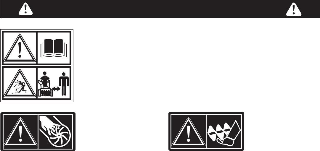
SAFETY
Readandunderstandtheoperatinginstructionsbeforeusing.
Keep the area of operation clear of all persons, especially small children and pets.
Thoroughlyinspecttheareatobeclearedandremovealldoormats,sleds,boards,
wiresandotherforeignobjects.Useextremecautionwhenoperatingonorcrossing
gravelsurfaces.Neverdirectdischargeatbystandersorallowanyoneinfrontofthe
snow thrower.
Do not place hands near rotating parts. Keep clear of the
discharge opening at all times.
Do not place feet near rotating parts.
• Neverallowchildrentooperatetheequipment.
• Neverallowadultstooperatetheequipmentwithout
proper instruction.
• Disengageallclutchesandshiftintoneutralbefore
starting engine.
• Donotoperateequipmentwithoutwearingadequate
winter outer garments.
• Wearsubstantialfootwearwhichwillprotectfeetand
improvefootingonslipperysurfaces.
• Checkfuelbeforestartingtheengine.Donotremove
thefuelcaporllthefueltankwhiletheengine
isrunningorhot.Donotllthefueltankindoors.
Gasolineisanextremelyammablefuel.
• Makesurethesnowthrowerheightisadjustedto
clearthetypesurfaceitwillbeusedon.
• Donotusethesnowthrowerwithoutwheelweights
attached to the tractor.
• Nevermakeanyadjustmentswhiletheengineis
running.
• Alwayswearsafetyglassesoreyeshieldduring
operationorwhileperformingadjustmentorrepair.
• Donotplacehandsorfeetnearrotatingparts.Keep
clear of the discharge opening at all times.
• Donotcarrypassengers.
• Afterstrikingaforeignobject,stoptheengine,remove
the wire from the spark plug and then thoroughly
inspect the snow thrower for damage. Repair any
damagebeforerestartingandoperatingthesnow
thrower.
• Ifthesnowthrowerstartstovibrateabnormally,stop
the engine immediately and check for the cause.
Vibrationisgenerallyawarningoftrouble.
• Stoptheenginewheneveryouleavetheoperating
position,beforeuncloggingthesnowthroweror
makinganyadjustmentsorinspections.
• Takeallpossibleprecautionswhenleavingtheunit
unattended.Disengagetheattachmentclutchleveror
switch, lower the snow thrower, shift into neutral, set
theparkingbrake,stoptheengineandremovethekey.
• Whencleaning,repairingorinspecting,makecertain
allmovingpartshavestopped.Disconnectthespark
plugwireandkeepitawayfromtheplugtoprevent
accidental starting.
• Donotrunengineindoorsexceptwhentransporting
thesnowthrowerinoroutofthebuilding.Openthe
outsidedoors.Exhaustfumesaredangerous.
• Donotclearsnowacrossthefaceofslopes.Exercise
extremecautionwhenchangingdirectiononslopes.
Do not attempt to clear steep slopes. Refer to the
slope guide on page 35 of this manual.
• Neveroperatethesnowthrowerwithoutguards,
platesorothersafetyprotectiondevicesinplace.
• Neveroperatethesnowthrowernearglass
enclosures,automobiles,windowwells,dropoffs
etc.withoutproperadjustmentofthesnowthrower
discharge angle.
• Neverrunthesnowthrowerintosnowathighspeeds.
• Donotoverloadthesnowthrowercapacityby
attempting to clear snow at too fast a rate.
• Neveroperatethesnowthrowerathightransport
speedonslipperysurfaces.Lookbehindandusecare
whenbackingup.
• Watchfortrafcandstayalertwhencrossingor
operating near roadways.
• Disengagepowertothesnowthrowerwhen
transporting or when not in use.
• Useonlyattachmentsandaccessoriesapprovedby
the manufacturer of the snow thrower (such as wheel
weights,counterweights,cabsetc.)
• Neveroperatethesnowthrowerwithoutgoodvisibility.
184045
199683199682

4
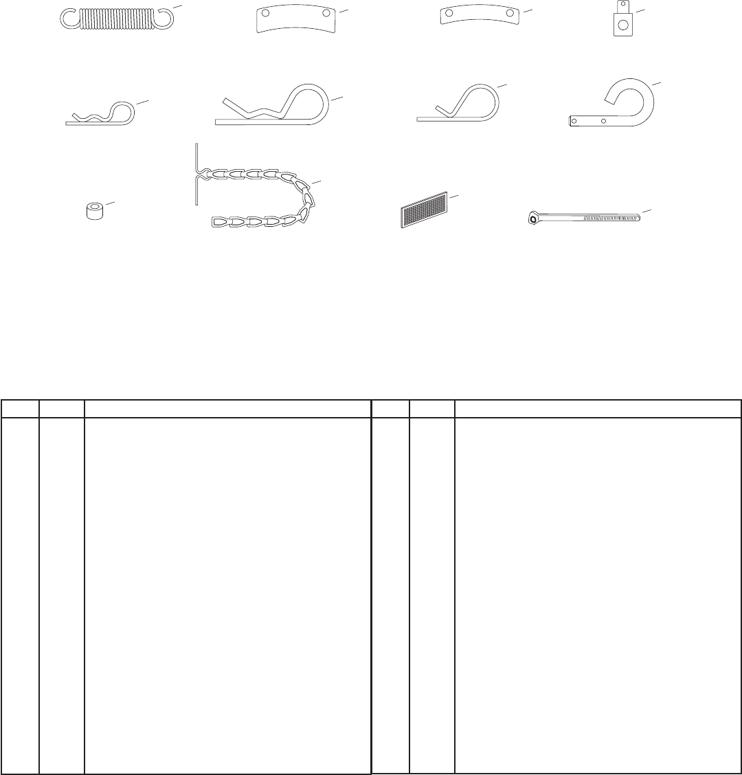
HARDWARE PACKAGE CONTENTS
SHOWN ACTUAL SIZE
43063
A B C DEF
O
H I J K L
MN
P
Q
R,S
ZAA
Y
X
V
U
T
46938
42849
43003
47605, 43070
43088 43081
47631
47630
44695
43082 47810 47572 46584
R19172410
44215
43682
44326
43080
47598
43084
43350
48106
49933
43661
G
43182
W
5
REF. QTY. DESCRIPTION
A 1 HexBolt,3/8"x3-1/4"
B 2 HexBolt,5/16"x1-3/4"
C 4 HexBolt,5/16"x1"
D 4 HexBolt,5/16"x3/4"
E 6 HexBolt,1/4"x1"
F 4 ShoulderBolt,HexHead
G 2 Shoulder Bolt, Round Head
H 2 Shear Bolt (spare parts)
I 6 CarriageBolt,3/8"x1"
J 2 CarriageBolt,5/16"x1-3/4"
K 2 CarriageBolt,5/16"x1-1/4"
L 4 CarriageBolt,5/16"x1"
M 2 CarriageBolt,5/16"x3/4"
N 6 HexBolt,3/8"x1"(ThreadForming)
O 2 HexBolt,5/16"x3/4"(ThreadForming)
P 7 Washer,1/4"
Q 22 Washer,5/16"(Extrawashersincluded)
R 1 Washer,3/8"(Thin)
S 3 Washer,3/8"Standard
T 8 Washer,1/2"x1-1/2"
REF. QTY. DESCRIPTION
U 2 Bowed Washer
V 7 LockWasher,3/8"
W 2 HexLockNut,3/8"
X 22 NylockNut,5/16"(2spareparts)
Y 10 FlangedNut,3/8"
Z 1 FlangedNut,5/16"
AA 6 FlangedNut,1/4"
BB 1 Spring
CC 3 Chute Keeper
DD 3 Chute Spacer
EE 1 Trunnion
FF 2 HairpinCotter,5/64"
GG 4 HairpinCotter,1/8"
HH 1 HairpinCotter,3/32"
II 2 Lock Pin
JJ 1 Spacer,3/8"
KK 2 Chain, Tensioning
LL 2 TailReector
MM 2 Nylon Tie
IMPORTANT: Notallitemssuppliedinthehardwarebagwillbeneededforyourparticulartractor.Unneededitemsmay
bediscardedafteryouhavecompletedassemblyandcheckedoperationofunit.DO NOT DISCARD the two spare shear
bolts(H)and5/16"nylocknuts(X).RefertotheServiceandAdjustmentssectiononpage28.
MM
GG
EEDDCCBB
NOT SHOWN ACTUAL SIZE
FF
LL
HH II
JJ
KK
46959 27809 27810 42848
HA3090 43343 43055 43038
46963 726-0178
47788
23727
6
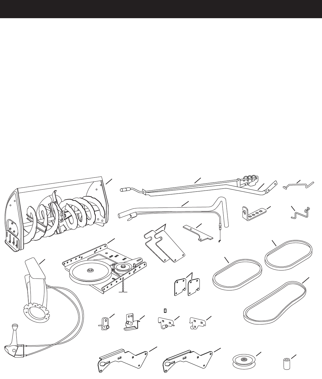
CARTON CONTENTS
1. HousingAssembly
2. LiftHandleandCable
3. ChuteCrankRodAssembly
4. SupportTube,CrankRod
5. Engagement Rod (Not used on some models)
6. CableBracket
7. Engine Pulley Keeper (Not used on some models)
8. ChuteandControlCableAssembly
9. ClutchIdlerAssembly
10. Rear Pulley Frame Bracket (2)
11. Anti-rotation Bracket.
12. Front Pulley Frame Bracket (2)
13. V-Belt,Drive56"(#48138)
14. V-Belt,Drive55"(#46989)
15. V-Belt,Auger(AttachedtoHousingAssembly)
16. L.H. Hanger Bracket (Outside Mounting)
17. R.H. Hanger Bracket (Outside Mounting)
18. L.H. Hanger Bracket (Inside Mounting)
19. R.H. Hanger Bracket (Inside Mounting)
20. Left Hand Side Plate
21. Right Hand Side Plate
22. Pulley
23. Spacer,3/8"
46989
48138
42992
20
11
5
7
17
2
4
6
19
18
16
8
15
13
1
9
3
21
14
25678
25679
27509
64452
64451
65450
65367
47043
46948
25728
24558
10
12
27016
48883 25780
22 23
7
TOOLS REQUIRED FOR ASSEMBLY
(2)7/16"Wrenches
(2)1/2"Wrenches
(2)9/16"Wrenches
(2)3/4"Wrenches
(1)ScrewDriver
(1) Knife
ADDITIONAL ITEMS REQUIRED
General Purpose Grease
ASSEMBLY
• Removealllooseparts,partsbagsandhardware
bagsfromthecarton.Layoutandidentifypartsand
hardware using the illustrations on pages 4, 5 and 6.
IMPORTANT: Not all items supplied in the hardware
bagwillbeneededforyourparticulartractor.Unneeded
itemsmaybediscardedafteryouhavecompleted
assemblyandcheckedoperationofunit.DO NOT
DISCARDthetwospareshearboltsand5/16"nylock
nuts.RefertotheServiceandAdjustmentssectionon
page 28.
REMOVAL OF PARTS FROM CARTON
TRACTOR PREPARATION
Beforeperformingtheseinstructions,refertotheService
andAdjustmentssectionofyourtractorowner'smanual
forspecicsafetyinstructions.
• Allowengine,muferandexhaustdeectortocool
beforebeginning.
• Removeanyfrontorrearattachmentwhichis
mounted to your tractor.
• Removethemowerdeck.Refertoyourtractorowner's
manualforremovalinstructions.Markalllooseparts
andsaveforreassembly.
• Removethetractorhood.Refertoyourtractorowner's
manualforremovalinstructions.
CAUTION: Before starting to assemblethe
snowthrower,removethesparkplugwire(s),
settheparking brake and removethekey
from the tractor ignition.
IMPORTANT: Right hand (R.H.) and left hand (L.H.) side
of the tractor are determined from the operators position
while seated on the tractor.
MOWER DECK
SUSPENSION
BRACKET
FIGURE 1
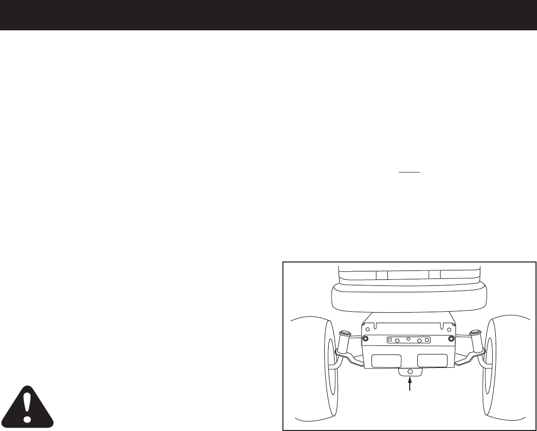
IDENTIFY YOUR TRACTOR
STEP 1: (SEE FIGURE 1)
• Locatethefrontmowerdecksuspensionbracket(s).
A. If there is a single mower deck suspension
bracketlocatedunderneaththemiddleofthefront
axle,continueontostep2onthenextpage.
OR
B. Ifyourtractordoesnothaveamowerdeck
suspensionbracketunderneaththemiddleofthe
frontaxle,skiptostep21onpage14forinstructions
for tractors with dual side mounted mower deck
suspensionbrackets.
8
FIGURE 2 RIGHT SIDE VIEW
REMOVE
FRONT SCREWS
REMOVE
BROWNING SHIELD
INSTRUCTIONS FOR TRACTORS WITH
A SINGLE FRONT DECK SUSPENSION
BRACKET
STEP 2: (SEE FIGURE 2)
• Removethebrowningshieldfromthefrontofthe
tractorasshown.Holdontotheshieldasyouremove
thesecondscrewtopreventitfromfalling.
• Besuretoreinstallthebrowningshieldwhenso
instructed in step 3.
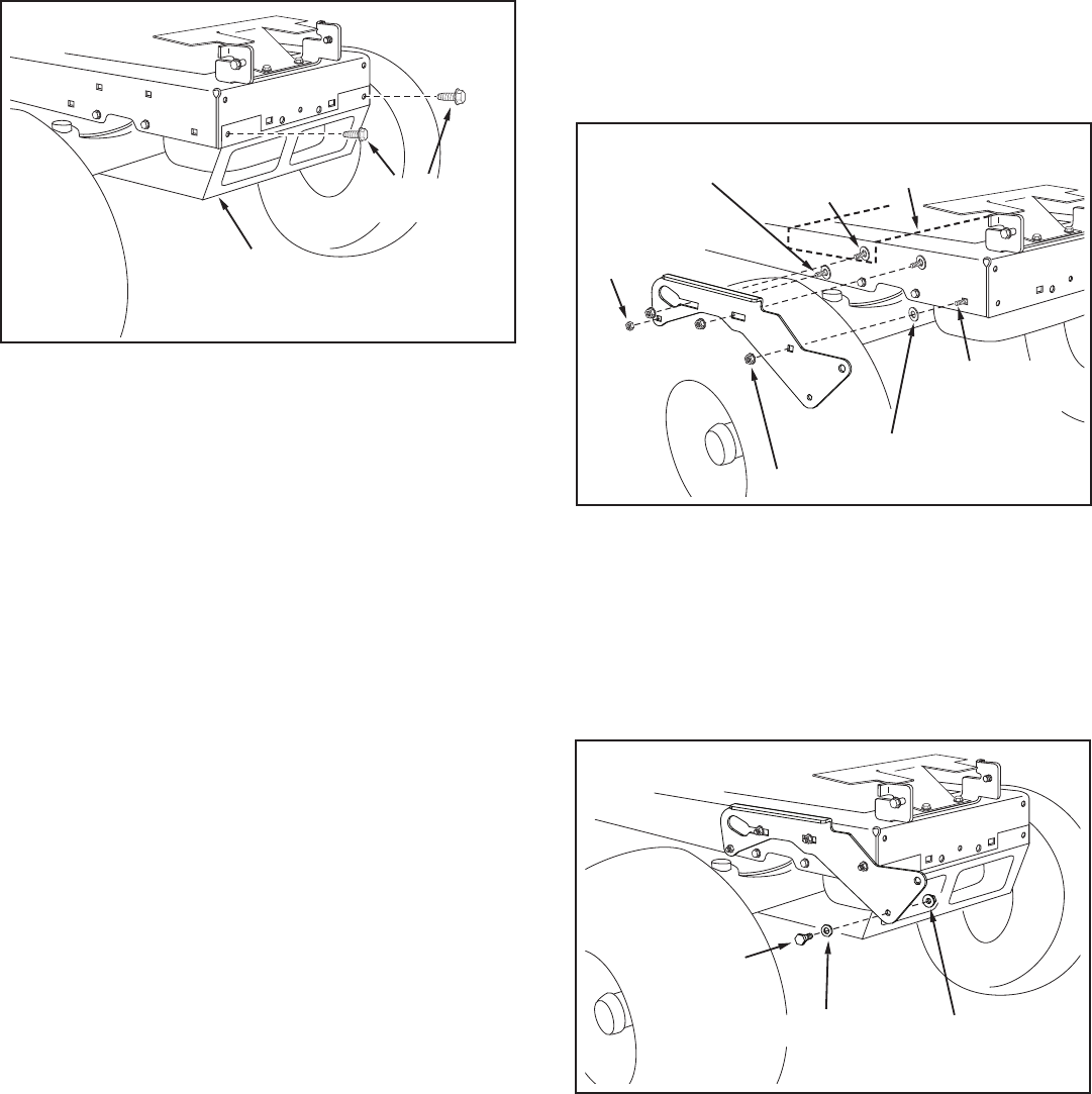
STEP 4: (SEE FIGURE 4)
• Assembleashoulderboltanda3/8"washertothe
outsideofR.H.sideplate,securingitwitha3/8"
angednut.RepeatforL.H.sideplate.
FIGURE 4 RIGHT SIDE VIEW
FIGURE 3 RIGHT SIDE VIEW
5/16"
NYLOCK
NUT
5/16" x 1"
CARRIAGE BOLT ENGINE MOUNTING
PLATE
(3) 3/8" FLANGE NUTS
(3) 3/8" x 1"
CARRIAGE
BOLTS
SEE NOTE
(4) 1/2" x 1-1/2" WASHERS
3/8" WASHER
SHOULDER
BOLT
3/8" FLANGED
NUT
INSTALL SIDE PLATES
STEP 3: (SEE FIGURE 3)
• FastentheR.H.SidePlate(bendfacingout)tothe
frontthreeholesinthetractorframeusingthree3/8"
x1"carriagebolts,three1/2"x1-1/2"washers(see
note)andthree3/8"angenuts. For the rear hole, use
a5/16"x1"carriagebolt,a1/2"x1-1/2"washerand
a5/16"nylocknut Placethewashersbetweenthe
tractor frame and the side plate. Repeat for L.H. side
plate.
• Reinstallthebrowningshieldontothetractorframe
using the original screws.
NOTE: If there is an engine mounting plate (shown with
dottedlines)leavethewasherofftheboltthatgoes
through the plate.

9
INSTALL HANGER BRACKETS AND SHOULDER
BOLTS TO OUTSIDE OF FRAME
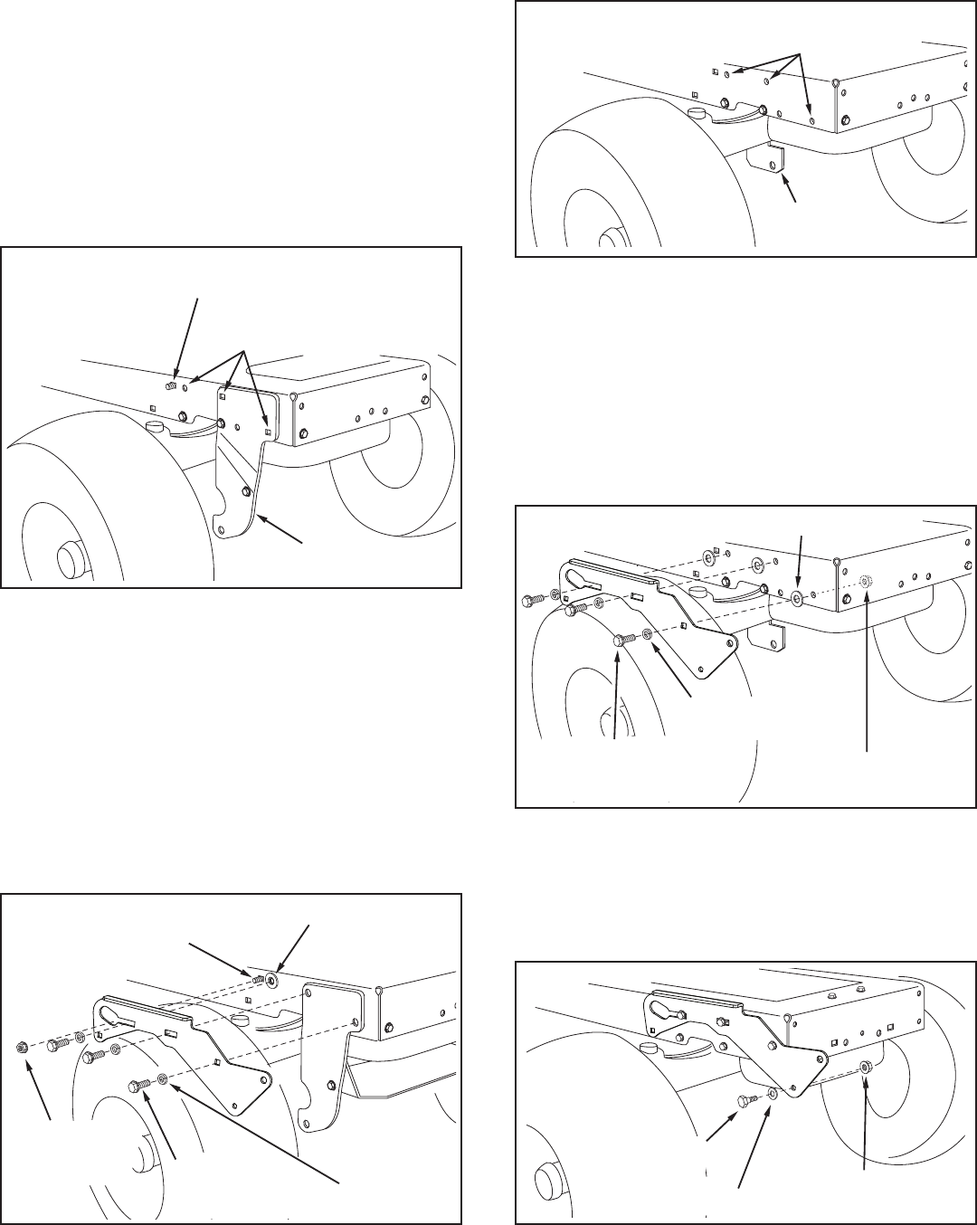
STEP 5: (SEE FIGURE 5)
• Removethebolt,ifpresent,intheholedirectlybehind
thebrakerodontheleftsideofthetractorframe.
• AttachtheL.H.HangerBracket(tubefacingout)tothe
holeusinga5/16"x3/4"selfthreadingbolt.
• Installaroundheadshoulderboltintotheholethatis
9-1/2"totherearoftheboltyoujustinstalled.Secure
itwitha3/8"angenutontheinsideoftheframe.
FIGURE 5 LEFT SIDE VIEW
5/16" x 3/4" SELF
THREADING BOLT
L.H. HANGER
BRACKET
BRAKE ROD
3/8" FLANGED
NUT
SHOULDER
BOLT
5/16" x 3/4" SELF
THREADING BOLT
R.H. HANGER
BRACKET
RIGHT END OF
BRAKE ROD
3/8" FLANGED
NUT
SHOULDER
BOLT
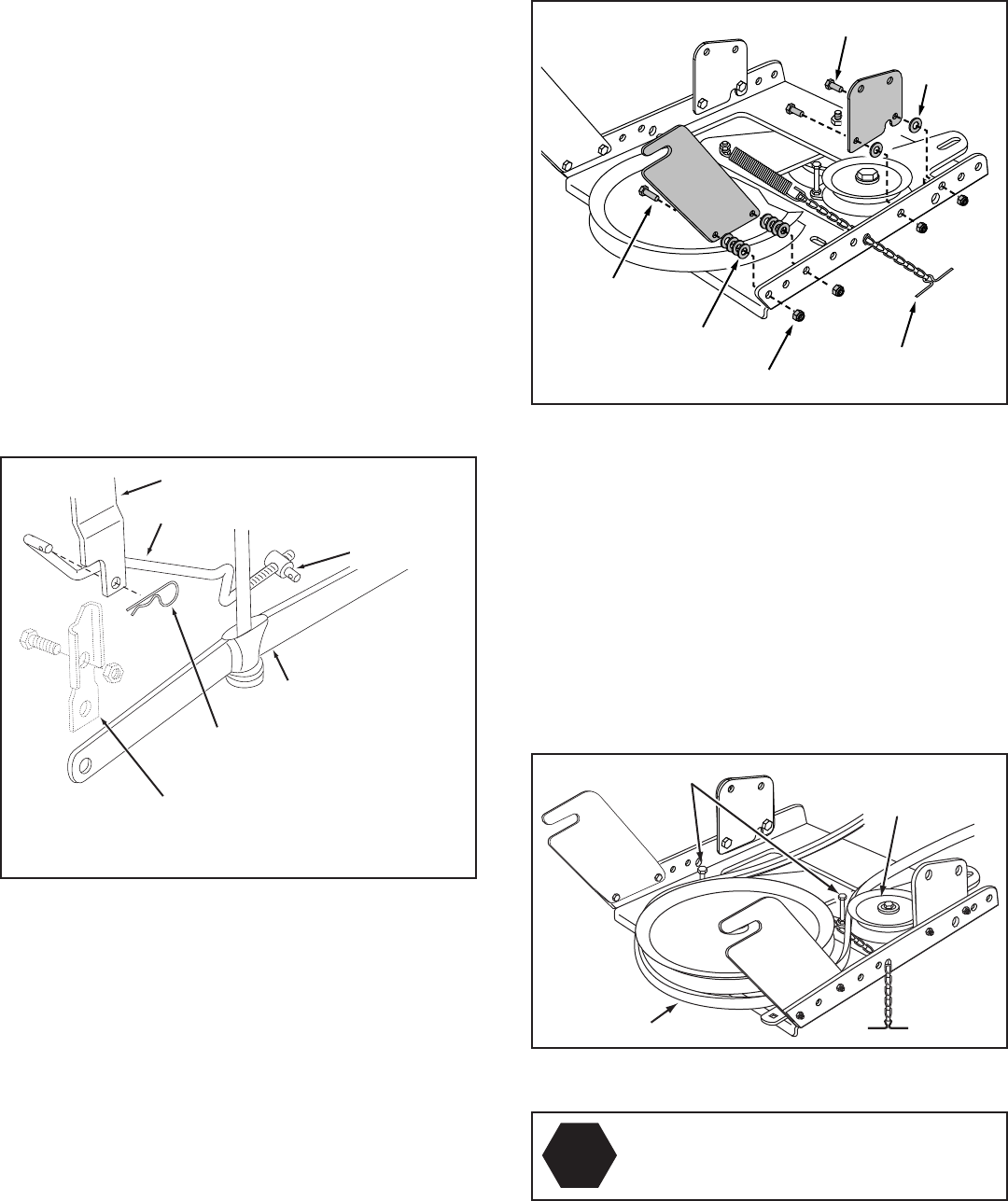
STEP 6: (SEE FIGURE 6)
• Removethebracket,ifpresent,fromtheholedirectly
behindtheendofthebrakerodontherightsideof
thetractorframe.Storethebracketandbolt.
• AttachtheR.H.HangerBrackettotheholeusinga
5/16"x3/4"selfthreadingbolt.
• Installaroundheadshoulderboltintotheholethatis
9-1/2"totherearoftheboltyoujustinstalled.Secure
itwitha3/8"angenutontheinsideoftheframe.
FIGURE 6 RIGHT SIDE VIEW
10
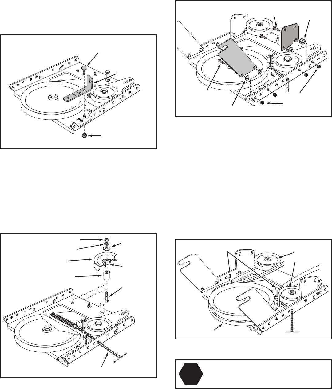
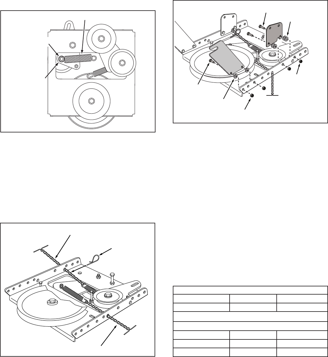
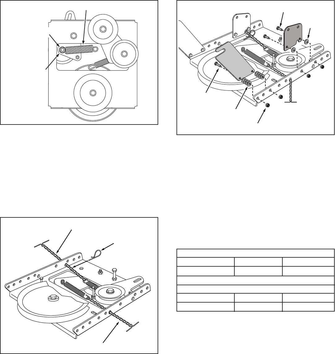
STEP 8: (SEE FIGURE 8)
• Attachthepulley(longendofhubfacingdown)and
the3/8"spacertotheclutch/idlerassembly.Use
a3/8"x3-1/4"hexbolt,a3/8"washer,a3/8"lock
washeranda3/8"hexlocknut.
• Insertatensioningchainthroughtheholeshownand
attach the end link to the spring on the lower idler arm.
FIGURE 8
FIGURE 7
STEP 7: (SEE FIGURE 7)
• Attachthecablebrackettothedoubleholeinthe
clutch/idlerassemblyasshown,usinga5/16"x3/4"
carriageboltanda5/16"nylocknut.Placetheboltin
thefrontholeofthebracketandintheendofthehole
closest to the pulley. Do not tighten yet.
THIS SECTION IS FOR TRACTORS WITH A
MANUAL ATTACHMENT CLUTCH
If your tractor has an electric attachment clutch go to
step 14 on page 12.
FIGURE 10
HEX BOLTS
(#48138)
DRIVE BELT
FLAT IDLER
PULLEYS
STOP
Didyouselectthecorrectdrivebeltforyour
tractor?Usingthewronglengthbeltmay
causeprematurebearingorbeltfailure.
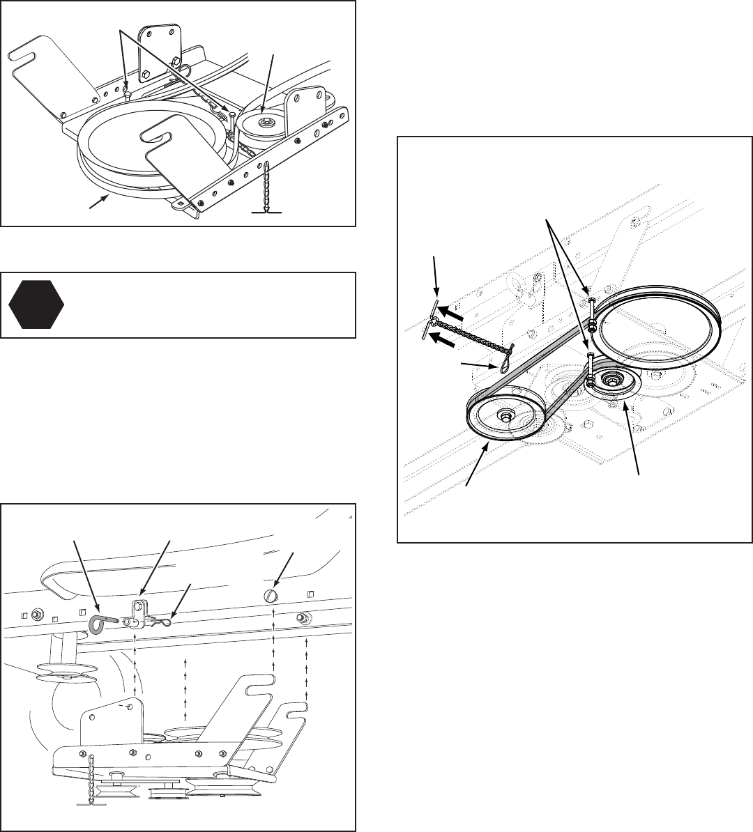
STEP 10: (SEE FIGURE 10)
• Twodifferentlengthdrivebeltsareincludedwith
your snow thrower. Tractors with manual attachment
clutchesandsinglefrontdecksuspensionbracketsuse
the56"drivebeltwith#48138 printed on the outside of
thebelt.DO NOT USEtheotherdrivebelts.
• Slightlyloosenthehexboltnexttotheatidlerpulley.
Installthedrivebeltdownbetweenthehexboltandthe
atidlerpulleywiththeatsideofthebeltagainstthe
pulley.Retightenthehexbolt.
• Loopthebeltaroundthelargev-pulley,placingit
betweenthev-pulleyandthehexboltnexttothepulley.
Placethebelttotheinsideoftheotheratidlerpulley.
5/16" x 1"
HEX BOLT
5/16" x 3/4"
HEX BOLT 5/16"
NYLOCK
NUT
5/16" WASHER
(2) 5/16"
WASHERS
FIGURE 9
STEP 9: (SEE FIGURE 9)
• Attacheachrearpulleyframebrackettotheinsideof
theclutch/idlerassemblyusingtwo5/16"x3/4"hex
bolts,5/16"washersand5/16"nylocknuts.
• Attacheachfrontpulleyframebrackettotheinside
oftheclutch/idlerassemblyusingtwo5/16"x1"hex
bolts,four5/16"washersandtwo5/16"nylocknuts.
3/8" SPACER
PULLEY
3/8" LOCKWASHER
3/8" HEX LOCK NUT 3/8"
WASHER
LONG END
OF HUB
3/8" x 3-1/4"
HEX BOLT
TENSIONING CHAIN
CABLE
BRACKET
5/16" x 3/4"
CARRIAGE BOLT
5/16" NYLOCK
NUT

11
ATTACH CLUTCH IDLER ASSEMBLY TO TRACTOR
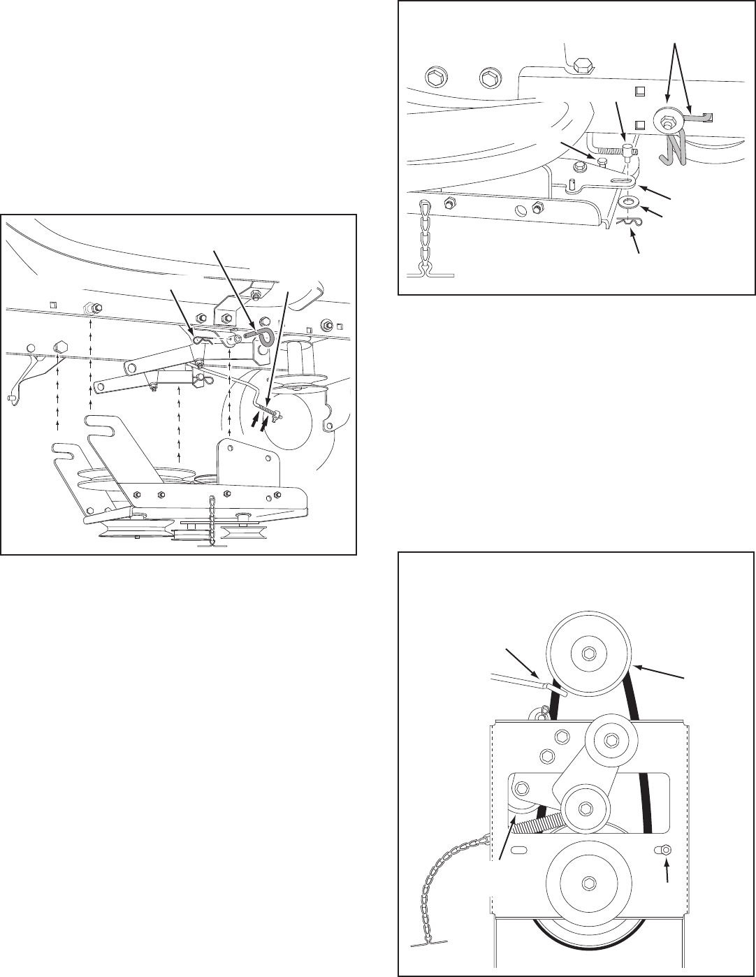
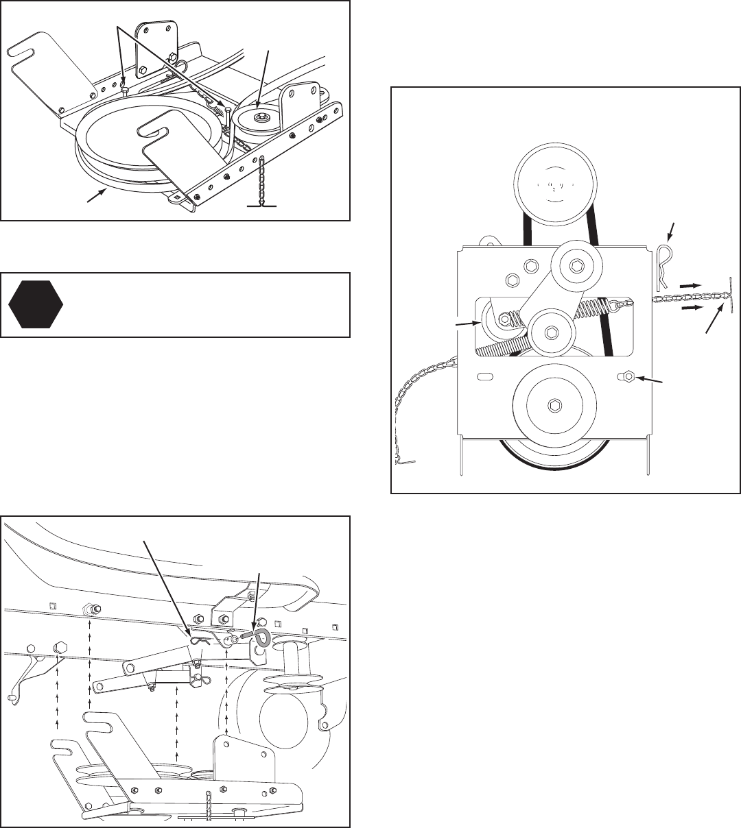
STEP 12: (SEE FIGURE 12)
• Attachtheclutch/idlerassemblytothetractorframe.
Hookthenotchedrearpulleyframebracketsontothe
twoshoulderboltsassembledtotheoutsideofthe
tractorframe.Liftthefrontoftheassemblyandattach
ittotheR.H.andL.H.hangerbracketsusingtwopivot
lockpinsand1/8"hairpincotters.
• Looselyattachthemowerclutchcabletotheleftside
of the tractor frame with a nylon tie. Do not pull the
nylontiecompletelytight.Thecablemayneedtobe
removedfromthenylontiewhenusingthemower
deck.
PIVOT LOCK PIN
(use this hole)
SHOULDER
BOLT
L.H. HANGER
BRACKET
1/8" HAIRPIN
COTTER
NYLON TIE
MOWER
CLUTCH
CABLE
FIGURE 12 VIEWED FROM LEFT SIDE
STEP 13: (SEE FIGURE 13)
• Assemblethedrivebeltontotheenginepulleyrst
and then onto the large pulley on top of the clutch/
idlerassembly.Thebeltmustbeplacedinsidethe
enginepulleybeltkeeper(s)andbetweenthelarge
pulleyandthekeeperboltnexttoit.
IMPORTANT: Do Notassemblethe"V"beltoutsideof
theenginepulleykeepersoroutsideofthekeeperbolt
nexttothelargepulley.
• Go to step 48 on page 22.
FIGURE 13 VIEWED FROM UNDERNEATH
ENGINE
PULLEY
ENGINE
PULLEY
Left Side
of Tractor
ENGINE
PULLEY
KEEPER
ENGINE
PULLEY
KEEPER
KEEPER BOLT
IDLER
PULLEY
FIGURE 11
STEP 11: (SEE FIGURE 11)
• Findthecableclipthatisattachedtotheleftside
of the tractor frame underneath the footrest. Open
theclipandremovethemowerclutchcable.Do not
removetheclipfromthetractorframe.Thecable
reattaches to the clip when using the mower deck.
• Movetheattachmentclutchleveronthedashpanelto
the disengaged position.
• Placetheclutch/idlerassemblyontheoorontheleft
side of the tractor.
• Attachthetractor'smowerclutchcabletothecable
bracketontheclutch/idlerassembly.Securethecable
housingguide(groovedown)tothecablebracket
usingtheoriginalcollaranda5/64"haircotterpin.
• Placea1/4"spacerontheweldedpinontheidler
arm.Hooktheendoftheclutchcablespringoverthe
pinandsecureitwitha1/4"washeranda5/64"hair
cotter pin.
• Aligncablebracketwithweldedpinandtightenthe
nutassembledinstep9.
5/64" HAIR
COTTER PIN
1/4" WASHER
1/4" SPACER
5/64" HAIR
COTTER PIN
TRACTOR'S
CLUTCH CABLE
CABLE
BRACKET
12
FIGURE 16
STEP 17: (SEE TABLE 1)
• Twodifferentlengthdrivebeltsareincludedwithyour
snowthrower.Selectoneofthetwobeltslistedbelow
thatiscorrectforyourtractor.Thepartnumberis
printedontheoutsideofthebelt.
• Setasidethebeltsthatarenotforyourtractor,to
avoidaccidentallyusingthem.
SELECT THE CORRECT DRIVE BELT
(Electric clutch tractors with a single front deck
suspension bracket)
55" BELT (PART #46989)
TRACTOR TYPE DECK SIZE CLUTCH TYPE
(LT)LawnTractor 38",42" Electric
56" BELT (PART #48138)
TRACTOR TYPE DECK SIZE CLUTCH TYPE
(LT)LawnTractor 48" Electric
(GT)GardenTractor 48",54" Electric
TABLE 1
5/16" x 1" HEX BOLT
5/16" x 3/4"
HEX BOLT
5/16" NYLOCK NUT
5/16" WASHER
5/16"
NYLOCK NUT
(2) 5/16" WASHERS
STEP 16: (SEE FIGURE 16)
• Attacheachrearpulleyframebrackettotheinsideof
theclutch/idlerassemblyusingtwo5/16"x3/4"hex
bolts,5/16"washersand5/16"nylocknuts.
• Attacheachfrontpulleyframebrackettotheinside
oftheclutch/idlerassemblyusingtwo5/16"x1"hex
bolts,four5/16"washersandtwo5/16"nylocknuts.
THIS SECTION IS FOR TRACTORS WITH AN
ELECTRIC ATTACHMENT CLUTCH
3/8" HEX
LOCK NUT
SPRING
ATTACH
SPRING
HERE
STEP 14: (SEE FIGURE 14)
• Turntheclutchidlerassemblyupsidedown.
• Hookthespringontotheendoftheboltthatextends
throughthenutonthebottomoftheupperidler
arm.Installa3/8"hexlocknutontothebolt,leaving
enoughspaceforthespringtopivot.
FIGURE 14
FIGURE 15
STEP15: (SEE FIGURE 15)
• Inserttensioningchainsthroughtheholesshownand
attach to the springs on the upper and lower idler arms.
• Installa3/32"hairpincotterinthechainattachedto
theupperidlerarm,placingitinthefthlinkfromthe
spring.
TENSIONING CHAIN (lower idler arm)
TENSIONING CHAIN (upper idler arm)
3/32" HAIRPIN
COTTER IN
5th LINK
13
STEP 19: (SEE FIGURE 18)
• Attachtheclutch/idlerassemblytothetractorframe.
Hookthenotchedrearpulleyframebracketsontothe
twoshoulderboltsassembledtotheoutsideofthe
tractorframe.Liftthefrontoftheassemblyandattach
ittotheR.H.andL.H.hangerbracketsusingtwopivot
lockpinsand1/8"hairpincotters.
PIVOT LOCK PIN
(use second hole)
SHOULDER
BOLT
1/8" HAIRPIN
COTTER
L.H. HANGER
BRACKET
FIGURE 18 VIEWED FROM LEFT SIDE
STEP 20: (SEE FIGURE 19)
• Assemblethedrivebeltontotheenginepulley.You
mayneedtoremovethebeltfromthelargepulleyon
theclutch/idlerassemblyinordertoassembleitonto
theenginepulley.Whenre-assemblingthebeltonto
thelargepulley,besurethebeltisbetweenthelarge
pulleyandthehexboltnexttoit.
• Placetensiononthebeltbypullingtheleftside
tensioningchainoutasfarasthe3/32"hairpincotter
in the chain will allow. Secure the chain in this position
byinsertinga1/8"hairpincotterthroughthechain.
IMPORTANT: Do Notassemblethedrivebeltaroundthe
outsideofthekeeperboltbesidethelargepulley.
• Go to step 48 on page 22.
FIGURE 19 VIEWED FROM UNDERNEATH
FIGURE 17
STEP 18: (SEE FIGURE 17)
• Turntheclutch/idlerassemblyrightsideup.
• Slightlyloosenthehexboltnexttotheatidlerpulley.
Installthedrivebeltdownbetweenthehexboltandthe
atidlerpulleywiththeatsideofthebeltagainstthe
pulley.Retightenthehexbolt.
• Loopthebeltaroundthelargev-pulley,placingit
betweenthev-pulleyandthehexboltnexttothepulley.
STOP
Didyouchoosethecorrectdrivebeltfor
yourtractor?Usingthewronglengthbelt
maycauseprematurebearingorbeltfailure.
DRIVE BELT
FLAT IDLER
PULLEY
HEX BOLTS
1/8"
HAIRPIN
COTTER
ENGINE
PULLEY
HEX BOLTS
FLAT IDLER
PULLEY
TENSIONING
CHAIN
LEFT SIDE
OF TRACTOR
14
STEP 22: (SEE FIGURE 21)
• FastentheR.H.SidePlate(bendfacingout)tothe
front three holes shown in the tractor frame using
three3/8"x1"threadformingbolts,three3/8"lock
washersandone1/2"washer.Placethewasheron
thethirdboltasashimbetweenthesideplateand
theframe.Tightenallbolts.RepeatfortheL.H.side.
NOTE:Ifyouinstalledaboltinthefourthholeinstep21,
assemblea5/16"angenutontotheboltaftertheside
plate is installed.
• Go to step 25 on this page.
(3) 3/8" x 1"
THREAD FORMING
BOLTS
5/16" FLANGED
NUT
(SEE NOTE) (3) 3/8" LOCK
WASHERS
1/2" WASHER
5/16" x 1"
CARRIAGE BOLT
(SEE NOTE)
FIGURE 21 RIGHT SIDE VIEW
SUSPENSION
BRACKET
REMOVE BOLTS
IF PRESENT
FIGURE 22 RIGHT SIDE VIEW
STEP 23: (SEE FIGURE 22)
• Removeanyboltsfoundintheholesshown.
STEP 24: (SEE FIGURE 23)
• FastentheR.H.SidePlate(bendfacingout)tothe
threeholesshowninthetractorframe.Usethree3/8"
x1"threadformingbolts,1/2"washersand3/8"lock
washers.TightenallboltsandrepeatfortheL.H.side.
NOTE:Iftheboltinsertsfreelyintothefronthole,assemble
a3/8"angednutontothebolt.
(3) 3/8" x 1"
THREAD FORMING
BOLTS
(3) 3/8" LOCK
WASHERS
3/8" FLANGED NUT
(SEE NOTE)
(3) 1/2" WASHERS
FIGURE 23 RIGHT SIDE VIEW
STEP 21: (SEE FIGURE 20)
• Removeboltsfromfrontthreeholesshown.
• Ifaboltispresentinthefourthhole,replaceitwith
a5/16"x1"carriageboltwithoutanut.Thebracket
fastened to inside of frame must remain in place.
FRONT
SUSPENSION
BRACKET
REPLACE BOLT
(IF PRESENT)
REMOVE BOLTS
(IF PRESENT)
FIGURE 20 RIGHT SIDE VIEW
INSTRUCTIONS FOR TRACTORS WITH DUAL
FRONT DECK SUSPENSION BRACKETS
FASTEN SIDE PLATES TO TRACTOR
Ifyourtractorresemblesgure20,gotostep21.
Ifyourtractorresemblesgure22,gotostep23.
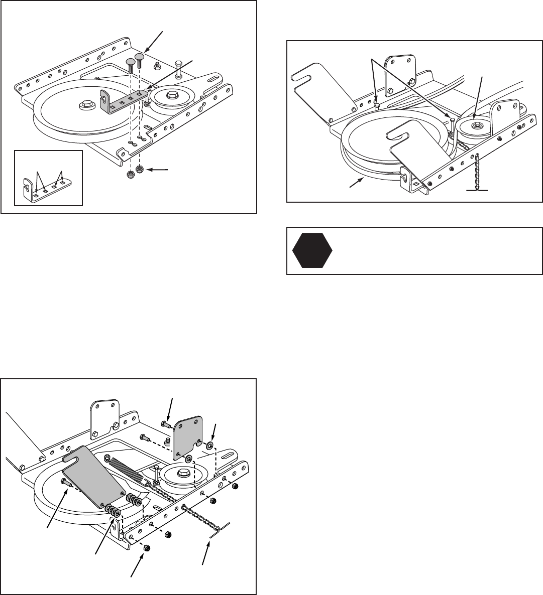
STEP 25: (SEE FIGURE 24)
• Assembleashoulderboltanda3/8"washertothe
outsideofeachsideplate,securingthemwitha3/8"
angednut.
FIGURE 24 RIGHT SIDE VIEW
3/8" WASHER
SHOULDER
BOLT 3/8" FLANGED
NUT
15
FIGURE 28 RIGHT SIDE VIEW
INSTALLING HANGER BRACKETS
Forbetterclearance,lowerthetractor'ssuspensionarms
usingtheattachmentliftlever.
STEP 26: (SEE FIGURE 25 or 26)
On Tractors With Foot Rest Brackets
• RemovetheboltandnutthatfastentheL.H.andR.H.
footrestbracketstotheframe.
• AttachtheL.H.HangerBracket(marked"L")tothe
insideofthetractorframeusingtwo3/8"x1"carriage
boltsand3/8"angednuts.Boltheadsgooninsideof
tractor frame. Repeat for the R.H. side.
FIGURE 26 LEFT SIDE VIEW
FIGURE 25 LEFT SIDE VIEW
On Tractors Without Foot Rest Brackets
• Findtheemptyholebeneaththefootrest.Attachthe
L.H.HangerBracket(marked"L")totheinsideof
theframeusinga3/8"x1"carriageboltanda3/8"
angednut.Boltheadgoesoninsideoftractorframe.
Repeat for the R.H. side.
STEP 28: (SEE FIGURE 28)
• Assembleashoulderboltand3/8"angednuttothe
R.H.sideofthetractorframe,usingtherstempty
holetotherearoftheR.H.hangerbracket.Boltgoes
on inside of frame.
FIGURE 27 LEFT SIDE VIEW
INSTALLING SHOULDER BOLTS
STEP 27: (SEE FIGURE 27)
• Removethebolt,washerandnutwhichfastenthe
swaybarbrackettotheL.H.sideofthetractorframe.
Replacewithashoulderboltanda3/8"angednut.
Bolt goes on inside of frame.
BOLT REMOVED
FROM THIS HOLE
SWAY BAR
BRACKET
SHOULDER BOLT
3/8"
FLANGED
NUT
3/8" x 1"
CARRIAGE
BOLT
3/8" FLANGED
NUT
L.H. HANGER
BRACKET
SUSPENSION ARM
SHOULDER BOLT
3/8"
FLANGED
NUT
R.H. HANGER BRACKET
BOLT REMOVED
FROM THIS HOLE
3/8" x 1"
CARRIAGE
BOLT
3/8" FLANGED
NUT
L.H. HANGER
BRACKET
SUSPENSION ARM
16
INSTALLING CLUTCH/IDLER ASSEMBLY
ThissectioncoverstheinstallationoftheClutch/Idler
assemblytotractorswithattachmentclutchesthatare
eitherrodoperated(p.16),cableoperated(p.18)or
electric (p. 20). Use the appropriate instructions for your
tractor.
ROD OPERATED MANUAL ATTACHMENT CLUTCH
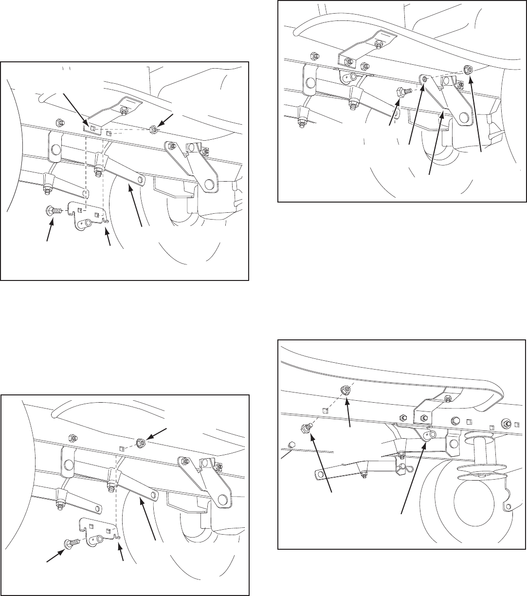
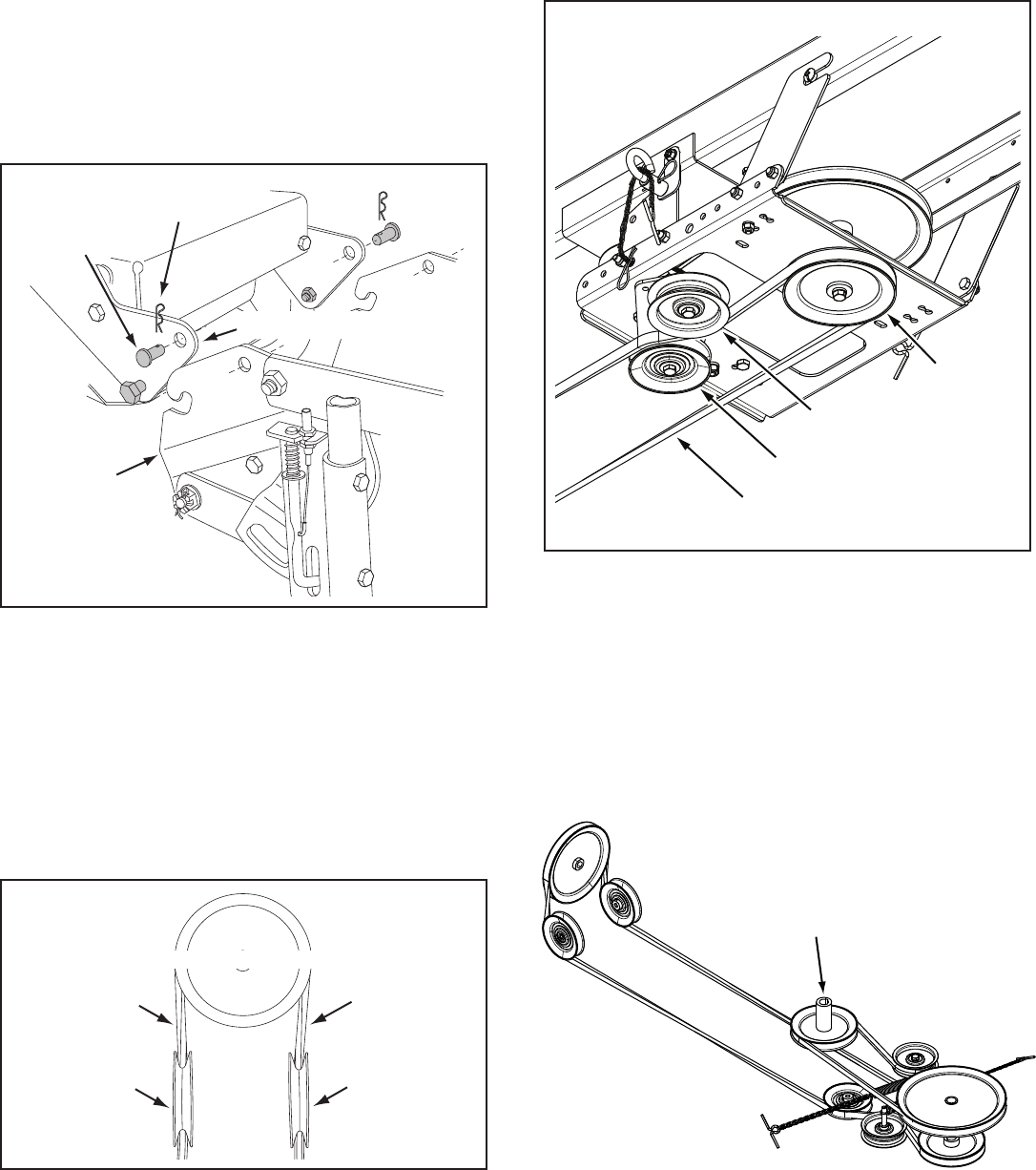
STEP 29: (SEE FIGURE 29)
• Movetheattachmentclutchleveronthedashpanelto
the disengaged (down) position.
• Screwthetrunnionontotheendofthesnowthrower
engagement rod.
• Locatetheclutcharm(wherethemowerclutchrod
was connected) underneath the right hand side the
tractor,justtotheinsideofthesuspensionarm.If
there is an extensionattachedtotheclutchlever,the
extension,boltandnutmustberemovedandstored
with the mower deck.
IMPORTANT: Re-attach the extension to the clutch
leverbeforereinstallingthemowerdeck.
• Positiontheengagementrodtotheinsideofthe
clutch arm and insert the drilled end of the rod
throughthearm.Securewitha5/64"hairpincotter.
FIGURE 29 RIGHT SIDE VIEW
STEP 30: (SEE FIGURE 30)
• Attachthetworearpulleyframebracketstotheinside
oftheclutch/idlerassemblyusingtwo5/16"x1"hex
bolts,eight5/16"washersandtwo5/16"nylocknuts
foreachbracket.
FIGURE 30
FIGURE 31
STOP
Didyouchoosethecorrectdrivebeltfor
yourtractor?Usingthewronglengthbelt
maycauseprematurebearingorbeltfailure.
STEP 31: (SEE FIGURE 31)
• Twodifferentlengthdrivebeltsareincludedwith
your snow thrower. Tractors with manual attachment
clutchesanddualfrontdecksuspensionbracketsuse
the55"drivebeltwith#46989 printed on the outside
ofthebelt.DO NOT USEtheotherbelts.
• Slightlyloosenthehexboltnexttotheatidlerpulley.
Installthedrivebeltdownbetweenthehexboltandthe
atidlerpulleywiththeatsideofthebeltagainstthe
pulley.Retightenthehexbolt.
• Loopthebeltaroundthelargev-pulley,placingit
betweenthev-pulleyandthehexboltnexttothepulley.
• Attachthetwofrontpulleyframebracketstotheinside
oftheclutch/idlerassemblyusingtwo5/16"x3/4"hex
bolts,5/16"washersand5/16"nylocknutsforeach
bracket.Addextrawashersifneeded.
• Insertatensioningchainthroughtheholeshownand
attach the end link to the spring on the lower idler arm.
#46989
DRIVE BELT
FLAT IDLER
PULLEY
HEX BOLTS
TENSIONING CHAIN
(lower idler arm)
5/16" x 3/4" HEX BOLT
5/16" x 1"
HEX BOLT
5/16" NYLOCK NUT
5/16"
WASHER
(4) 5/16" WASHERS
ENGAGEMENT ROD
5/64" HAIRPIN
COTTER
TRACTOR'S CLUTCH ARM
SUSPENSION ARM
TRUNNION
REMOVE EXTENSION,
BOLT AND NUT
(IF PRESENT)
17
FIGURE 33 RIGHT SIDE VIEW
FIGURE 32 RIGHT SIDE VIEW
STEP 33: (SEE FIGURE 33)
• Makesuretheattachmentclutchleveronthedash
panel is in the disengaged (down) position.
• Pivottheupperidlerarmsothatitrestsagainst
thestopboltandispointingtowardthefrontas
shown. Screw the trunnion along the threads of the
engagement rod until it is aligned at the front end of
the idler arm slot. Attach the trunnion to the slot using
the3/8"thinwasheranda5/64"hairpincotter.
• Removetheenginepulleykeeperfromthesideof
thetractorframebyremovingthewasherandnut
that secure the keeper. Attach the new pulley keeper
supplied with the snow thrower, reusing the original
bolt,washerandnut.
NOTE:Sometractorsmayalreadybeequippedwitha
pulley keeper that is identical to the new one supplied.
STEP 34: (SEE FIGURE 34)
• Assembletheshort"V"beltontotheenginepulley
and then onto the large pulley on top of the clutch/idler
assembly.Thebeltmustbeplacedtotheinsideofthe
engine pulley keeper, the idler pulley and the keeper
boltlocatedbesidethelargepulley.
IMPORTANT: Do Notassemblethe"V"beltaroundthe
outsideoftheenginepulleykeeperorthekeeperbolt.
• Go to step 48 on page 22.
FIGURE 34 VIEWED FROM UNDERNEATH
ENGINE
PULLEY
KEEPER BOLT
IDLER
PULLEY
ENGINE
PULLEY
KEEPER
Left Side
of Tractor
CLUTCH/IDLER ASSEMBLY
STEP 32: (SEE FIGURE 32)
• Besuretoliftupthefrontendoftheengagementrod
asshownwhenperformingthenextoperation.You
cantemporarilysupporttherodusingarubberband
tied to the engine pulley keeper.
• Attachtheclutch/idlerassemblytothetractorframe
asfollows.Hooktheassembly'snotchedrearpulley
framebracketsontothetwoshoulderboltsyou
assembledtotheinsideofthetractorframe.Liftthe
frontoftheassemblyandattachittotheR.H.andL.H.
hangerbracketsusingtwopivotlockpinsand1/8"
hairpin cotters.
PIVOT LOCK PIN (MM)
(use second hole)
1/8" HAIRPIN COTTER
ENGAGEMENT
ROD
IDLER ARM
5/64" HAIRPIN
COTTER
TRUNNION
STOP BOLT
3/8" THIN
WASHER
NEW ENGINE PULLEY KEEPER WITH
ORIGINAL BOLT, NUT AND WASHER
18
FIGURE 36
CABLE OPERATED MANUAL ATTACHMENT CLUTCH
FIGURE 37
STEP 37: (SEE FIGURE 37)
• Twodifferentlengthdrivebeltsareincludedwith
your snow thrower. Tractors with manual attachment
clutchesanddualfrontdecksuspensionbracketsuse
the55"drivebeltwith#46989 printed on the outside
ofthebelt.DO NOT USEtheotherbelts.
• Slightlyloosenthehexboltnexttotheatidlerpulley.
Installthedrivebeltdownbetweenthehexboltandthe
atidlerpulleywiththeatsideofthebeltagainstthe
pulley.Retightenthehexbolt.
• Loopthebeltaroundthelargev-pulley,placingit
betweenthev-pulleyandthehexboltnexttothepulley.
STOP
Didyouchoosethecorrectdrivebeltfor
yourtractor?Usingthewronglengthbelt
maycauseprematurebearingorbeltfailure.
STEP 36: (SEE FIGURE 36)
• Attachthetworearpulleyframebracketstotheinside
oftheclutch/idlerassemblyusingtwo5/16"x1"hex
bolts,eight5/16"washersandtwo5/16"nylocknutsfor
eachbracket.
• Attachthetwofrontpulleyframebracketstotheinside
oftheclutch/idlerassemblyusingtwo5/16"x3/4"hex
bolts,5/16"washersand5/16"nylocknutsforeach
bracket.Addextrawashersifneededinstep39.
• Insertatensioningchainthroughtheholeshownand
attach the end link to the spring on the lower idler arm.
FIGURE 35
STEP 35: (SEE FIGURE 35)
• Assemblethecablebrackettotheinnerhalfofthe
doubleholesinthebottomoftheclutch/idlerassembly
usingtwo5/16"x3/4"carriageboltsand5/16"nylock
nuts.Usethefrontholesinthecablebracketifyour
tractorhasa42"mowerdeck.Usetherearholesif
yourtractorhasa46"mowerdeck.
CABLE
BRACKET
5/16" x 3/4"
CARRIAGE BOLT
5/16" NYLOCK
NUT
42"
DECKS
46"
DECKS
#46989
DRIVE BELT
FLAT IDLER
PULLEY
HEX BOLTS
TENSIONING CHAIN
(lower idler arm)
5/16" x 3/4" HEX BOLT
5/16" x 1"
HEX BOLT
5/16" NYLOCK NUT
5/16"
WASHER
(4) 5/16" WASHERS
19
FIGURE 38
STEP 38: (SEE FIGURE 38)
• Movetheattachmentclutchleveronthedashpanelto
the disengaged (down) position.
• Placetheclutch/idlerassemblyontheoorontheright
side of the tractor.
• Attachthetractor'sclutchcabletothecablebracket.
Securethecablehousingguide(groovedown)tothe
cablebracketusingtheoriginalcollaranda5/64"hair
cotter pin.
• Placeaspacerontheweldedpinontheidlerarm.
Hooktheendoftheclutchspringoverthepinand
secureitwitha1/4"washeranda5/64"haircotterpin.
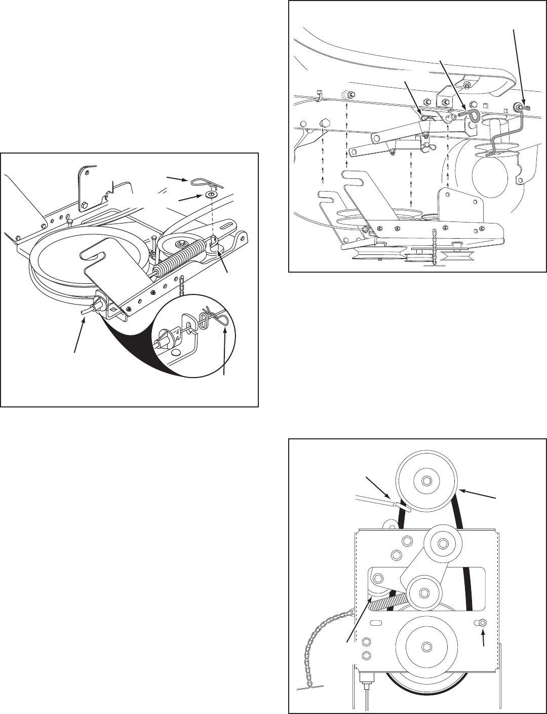
STEP 39: (SEE FIGURE 39)
• Removetheenginepulleykeeperfromthesideof
thetractorframebyremovingthewasherandnut
that secure the keeper. Attach the new pulley keeper
supplied with the snow thrower, reusing the original
bolt,washerandnut.
NOTE:Sometractorsmayalreadybeequippedwitha
pulley keeper that is identical to the new one supplied.
• Attachtheclutch/idlerassemblytothetractorframe
asfollows.Hooktheassembly'snotchedpulleyframe
bracketsontothetwoshoulderboltsyouassembled
to the inside of the tractor frame. Lift the front of the
assemblyandattachittotheR.H.andL.H.hanger
bracketsusingtwopivotlockpinsand1/8"hairpin
cotters.
FIGURE 39
NEW ENGINE PULLEY KEEPER WITH
ORIGINAL BOLT, NUT AND WASHER
PIVOT LOCK PIN
(use second hole)
1/8" HAIRPIN COTTER
FIGURE 40 VIEWED FROM UNDERNEATH
STEP 40: (SEE FIGURE 40)
• Assembletheshort"V"beltontotheenginepulley
and then onto the large pulley on top of the clutch/idler
assembly.Thebeltmustbeplacedtotheinsideofthe
engine pulley keeper, the idler pulley and the keeper
boltlocatedbesidethelargepulley.
IMPORTANT: Do Notassemblethe"V"beltaroundthe
outsideoftheenginepulleykeeperorthekeeperbolt.
• Go to step 48 on page 22.
ENGINE
PULLEY
KEEPER BOLT
IDLER
PULLEY
ENGINE
PULLEY
KEEPER
Left Side
of Tractor
5/64" HAIR
COTTER PIN
1/4" WASHER
TRACTOR'S
CLUTCH CABLE
5/64" HAIR
COTTER PIN
SPACER
20
ELECTRIC ATTACHMENT CLUTCHES
STEP 44: (SEE TABLE 2)
• Twodifferentlengthdrivebeltsareincludedwithyour
snowthrower.Selectoneofthetwobeltslistedbelow
thatiscorrectforyourtractor.Thepartnumberis
printedontheoutsideofthebelt.
• Setasidethebeltsthatarenotforyourtractor,to
avoidaccidentallyusingthem.
55" BELT (PART #46989)
TRACTOR TYPE DECK SIZE CLUTCH TYPE
56" BELT (PART #48138)
TRACTOR TYPE DECK SIZE CLUTCH TYPE
(LT)LawnTractor 48" Electric
(LT)LawnTractor 38",42",46" Electric
TABLE 2
FIGURE 43
STEP 43: (SEE FIGURE 43)
• Attachthetworearpulleyframebracketstotheinside
oftheclutch/idlerassemblyusingtwo5/16"x1"hex
bolts,eight5/16"washersandtwo5/16"nylocknuts
foreachbracket.
• Attachthetwofrontpulleyframebracketstotheinside
oftheclutch/idlerassemblyusingtwo5/16"x3/4"hex
bolts,5/16"washersand5/16"nylocknutsforeach
bracket.
3/8" HEX
LOCK NUT
SPRING
ATTACH
SPRING
HERE
STEP 41: (SEE FIGURE 41)
• Turntheclutchidlerassemblyupsidedown.
• Hookthespring(ontotheendoftheboltthatextends
throughthenutonthebottomoftheupperidler
arm.Installa3/8"hexlocknutontothebolt,leaving
enoughspaceforthespringtopivot.
FIGURE 41 BOTTOM VIEW
FIGURE 42
STEP 42: (SEE FIGURE 42)
• Inserttensioningchainsthroughtheholesshownand
attach to the springs on the upper and lower idler arms.
• Attacha3/32"hairpincottertothechainattachedto
theupperidlerarm,placingitinthefthlinkfromthe
spring.
TENSIONING CHAIN (lower idler arm)
TENSIONING CHAIN (upper idler arm)
3/32" HAIRPIN
COTTER IN
5th LINK
5/16" x 3/4" HEX BOLT
5/16" x 1"
HEX BOLT
5/16" NYLOCK NUT
5/16"
WASHER
(4) 5/16" WASHERS
21
FIGURE 46 VIEWED FROM UNDERNEATH
STEP 47: (SEE FIGURE 46)
• Assemblethedrivebeltontotheenginepulleyand
then onto the large pulley on top of the clutch/idler
assembly.Thebeltmustbeplacedtotheinsideof
theidlerpulleyandthekeeperboltlocatedbesidethe
large pulley.
• Placetensiononthebeltbypullingtheleftside
tensioningchainoutasfarasthe3/32"hairpincotter
willallow.Securethechaininthispositionbyinserting
a1/8"hairpincotterthroughthechain.
IMPORTANT: Do Notassemblethe"V"beltaroundthe
outsideoftheenginepulleykeeperorthekeeperbolt.
STEP 46: (SEE FIGURE 45)
• Attachtheclutch/idlerassemblytothetractorframe
asfollows.Hooktheassembly'snotchedrearpulley
framebracketsontothetwoshoulderboltsyou
assembledtotheinsideofthetractorframe.Liftthe
frontoftheassemblyandattachittotheR.H.andL.H.
hangerbracketsusingtwopivotlockpinsand1/8"
hairpin cotters.
FIGURE 45 RIGHT SIDE VIEW
PIVOT LOCK PIN
(use second hole)
1/8" HAIRPIN COTTER
CLUTCH/IDLER ASSEMBLY
DRIVE BELT
FLAT IDLER
PULLEY
HEX BOLTS
FIGURE 44
STOP
Didyouchoosethecorrectdrivebeltfor
yourtractor?Usingthewronglengthbelt
maycauseprematurebearingorbeltfailure.
STEP 45: (SEE FIGURE 44)
• Turntheclutch/idlerassemblyrightsideup.
• Slightlyloosenthehexboltnexttotheatidlerpulley.
Installthedrivebeltdownbetweenthehexboltandthe
atidlerpulleywiththeatsideofthebeltagainstthe
pulley.Retightenthehexbolt.
• Loopthebeltaroundthelargev-pulley,placingit
betweenthev-pulleyandthehexboltnexttothepulley.
1/8" HAIRPIN
COTTER
ENGINE
PULLEY
ENGINE
PULLEY
KEEPER
BOLT
IDLER
PULLEY
CHAIN
(L.H. SIDE)

22
STEP 48: (SEE FIGURE 47)
• Placethelifthandleintotheliftbracketontherightside
ofthesnowthrower.Fastenthehandletothebracket
usingtwo5/16"x1-3/4"hexboltsand5/16"Nylock
nuts.
FIGURE 48 RIGHT SIDE VIEW
LIFT RELEASE
CABLE
HEX NUT
LOCK
WASHER
HEX NUT
CABLE
WIRE
LIFT
ROD
TRIGGER
ASSEMBLY
NOTE:Besuretheliftreleasecable'splasticcovering
staysinsertedintothetriggerassemblyforthenextstep.
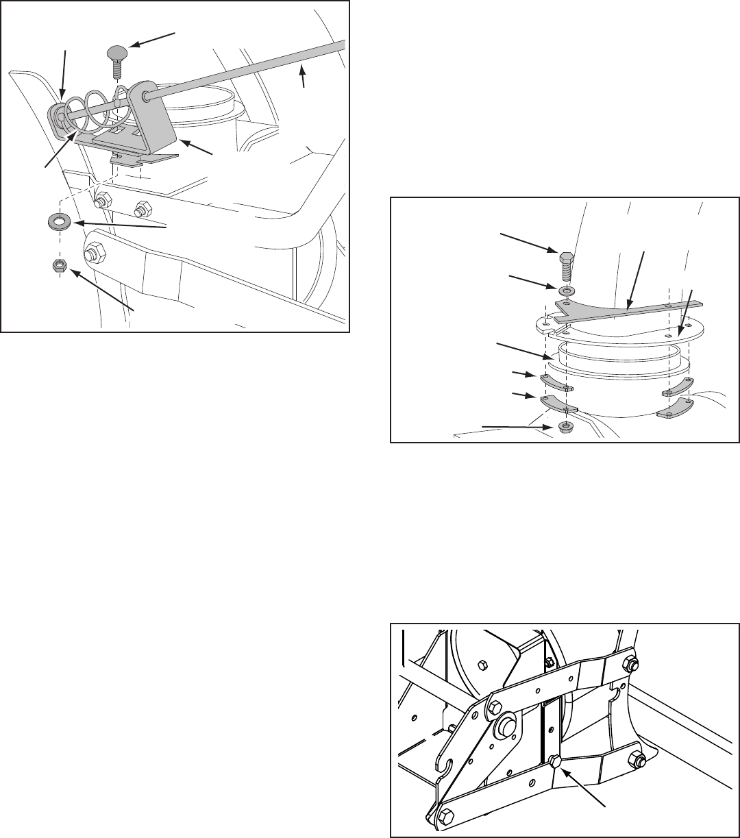
STEP 49: (SEE FIGURE 48)
• Pushthelifthandledownintothelockedposition.
Inserttheendofthecablewireintotheholeinthe
liftrod.Placethethreadedttingintotheslotinthe
liftbracket,withonehexnutaboveandonehexnut
andthelockwasherbelowtheslot.Tightenthenuts,
adjustingthemtoeliminateslackinthecablewire.
ReferalsototheServiceandAdjustmentssectionon
page 28 in this manual.
HINT: Foreasierassemblyoftheliftreleasecable,tiltthe
snow thrower forward onto the spiral auger.
FIGURE 47 RIGHT SIDE VIEW
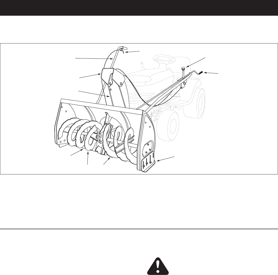
ASSEMBLY OF THE SNOW THROWER STEP 50: (SEE FIGURE 49)
• Tiltthesnowthrowerbackdowntotheground.
• Removethenylontiewhichfastenstheauger
drivebelttothedischargehousing,leavingthebelt
assembledaroundthepulleys.
• Removethenylontiewhichfastensthechutecrank
rodtothecrankrodsupporttube.
• Assemblethecrankrodsupporttubetothebracket
on the left side of the discharge housing using two
5/16"x1-1/4"carriagebolts,and5/16"Nylocknuts.
FIGURE 50 LEFT SIDE VIEW
CHUTE CRANK ROD
CRANK SUPPORT TUBE
TILT CONTROL HANDLE
5/16" x 1-3/4"
CARRIAGE BOLT
BOWED WASHER
5/16" NYLOCK NUT
TILT
CONTROL
ASSEMBLY
STEP 51: (SEE FIGURE 50)
• Attachthechutetiltcontrolassemblytothetopside
ofthecranksupporttubeusingtwo5/16"x1-3/4"
carriagebolts,bowedwashersand5/16"Nylocknuts.
5/16" NYLOCK NUT
5/16" x 1-1/4"
CARRIAGE BOLT
CRANK ROD
SUPPORT TUBE
DISCHARGE
HOUSING
FIGURE 49 LEFT SIDE VIEW
5/16" NYLOCK NUT
5/16" x 1-3/4"
HEX BOLT
23
5/16" NYLOCK NUT
CHUTE CRANK
BRACKET
5/16" WASHER
CHUTE
CRANK
ROD
ROD
SUPPORT
BRACKET
5/16" x 1"
CARRIAGE BOLT
SPIRAL
FIGURE 51 LEFT SIDE VIEW
FIGURE 52 RIGHT SIDE VIEW
STEP 53: (SEE FIGURE 52)
• Coatthetopoftheringaroundthedischargeopening
with general purpose grease.
• Placethedischargechute(facingforward)ontothe
ring.Placetheanti-rotationbracketontopofthechute
ange,aligningitwiththeholesontherighthand
sideoftheange.Attachthethreechutespacersand
chutekeeperstothebottomoftheangeusingsix
1/4"x1"hexbolts,1/4"atwashersand1/4"anged
lock nuts. Tighten the nuts.
• Positionthecrankrodspiral(seegure51)sothatit
doesnotrubagainstthebottomsofthenotchesinthe
chuteange.Tighten the nuts.
• Turnthecrankrodtocheckifthechuterotatesfreely.
Ifnot,loosenby1/4turneachofthesixhexboltsand
nuts attaching the chute spacers and chute keepers to
theange.
• Securethecontrolcablestothecrankrodsupport
tubeusinganylontie.
STEP 54: (SEE FIGURE 53)
Skip this step if you have a lawn tractor.
This step is for garden tractors only.
• Ifyouhavea(GT)GardenTractor,removethestop
boltsfromeachsideofthesnowthrowerframe.
STEP 52: (SEE FIGURE 51)
• Attachthechutecrankrodassemblybracketsto
theplasticbracketontheleftsideofthedischarge
housing.Alignthechutecrankbracketbeneaththe
rodsupportbracketandassemblebothtotheplastic
bracketusingtwo5/16"x1"carriagebolts,5/16"
washersand5/16"Nylocknuts.Do not tighten yet.
STOP BOLT
FIGURE 53 RIGHT SIDE VIEW
CHUTE KEEPER
CHUTE SPACER
ANTI-ROTATION
BRACKET
1/4" FLANGED
LOCK NUT
1/4" FLAT
WASHER
1/4" x 1"
HEX BOLT
GREASED
SURFACE
FLANGE
24
ATTACHING SNOW THROWER TO TRACTOR
STEP 56: (SEE FIGURE 55)
• Theaugerbeltcomespre-assembledtothepulleys
onthesnowthrowerhousing.Makesurethebelt
passesoverthetopoftheaugerpulleyandthen
twists 1/4 turn to pass underneath each side idler
pulley.The"V"sideofthebeltmustmatewiththe
groovesofthepulleys.
FIGURE 56 VIEWED FROM UNDERNEATH
STEP 57: (SEE FIGURE 56)
• Pushthelifthandledowntoincreaseslackinthebelt
(removeclevispinsifinstalledinstep55).
• Swingtheidlerarmovertotheside.
• Placetheaugerbeltaroundtherearpulleyand
betweenthetwoidlerarmpulleys.The"V"sideofthe
beltmustbeseatedinthegroovesoftheV-pulleys.
IDLER
PULLEY
AUGER PULLEY TWIST
1/4 TURN
TWIST
1/4 TURN
IDLER
PULLEY
FIGURE 55
1/8" HAIRPIN
COTTER
MOUNTING
PLATE
SIDE PLATE
CLEVIS PIN
1/2" x 7/8"
FIGURE 54 RIGHT SIDE VIEW
STEP 55: (SEE FIGURE 54)
• Placethesnowthroweronaat,levelsurface.
• Extendtheaugerbeltoutbehindthesnowthrower,
leavingthebeltassembledtothesnowthrowerpulleys.
• Rollthetractorupbehindthesnowthrower,centering
itbetweenthesnowthrower'smountingplates.
• Raisetherearofthesnowthrowerbyliftingupon
the lift handle until the notches in the mounting plates
alignwiththeshoulderboltsinthetractor'sside
plates.Guidetheboltsintothenotches.
• Delayinstallingtheclevispinsuntilyouhave
assembledthebeltasinstructedinsteps56and57.
BELT ROUTING DIAGRAM
ENGINE PULLEY
REAR
PULLEY
AUGER
BELT
IDLER ARM V-PULLEY
IDLER ARM
FLAT PULLEY
LEFT SIDE
OF TRACTOR
25
INSTALLING THE CLEVIS PINS
STEP 58: (REFER BACK TO FIGURE 54 ON PAGE 24)
• Liftthefrontofthesnowblowertoaligntheholesin
the mounting plates and the side plates. From the left
side of the tractor insert the attachment pin through
theholes.Secureitwithbyreinstallingthe1/8"hairpin
cotter.
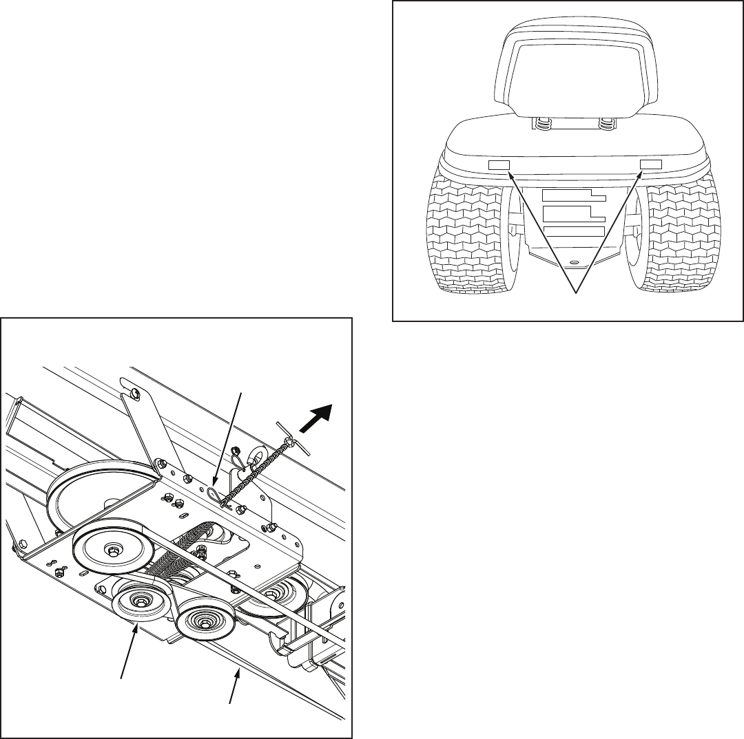
SETTING THE AUGER BELT TENSION
STEP 59: (SEE FIGURE 57)
• Pullthetensioningchainuntiltheendofthespringis
pulled through the hole in the side of the Clutch/Idler
assembly.Installa1/8"hairpincotterthroughtheend
of the spring, securing it on the outside of the Clutch/
Idlerassembly.
IMPORTANT:Forcorrectbelttension,the 1/8" hairpin
cotter should attach to the end of the spring, not to
the chain.
NOTE;Topreventthechainfromdraggingonthe
ground,looptheendofthechainthoughthepivotlock
pin.Refertogure45onpage21.
FIGURE 57 VIEWED FROM UNDERNEATH
CHECKLIST
Before you operate your snow thrower, please review
the following checklist to help ensure that you will
obtain the best performance from your snow thrower.
• Makesureallassemblyinstructionshavebeen
completedwithallboltsandnutsproperlytightened.
• Makesurethecorrectdrivebeltwasinstalled.
• Makesurethedrivebeltandaugerbeltarerouted
properlyaroundpulleysandinsideallbeltkeepers.
• Checkdischargechuteforproperrotation.
• Checkoperationoftiltcontrolforupperchute.
• Verifythatthelifthandlewilllockintoandrelease
from the raised transport position. (Refer to the
ServiceandAdjustmentssection.)
• Checkskidshoeadjustment.(RefertotheService
andAdjustmentssection.)
The following additional items are available from
Sears to help enhance the performance of your snow
thrower. See Accessories and Attachments on page 2.
• Tirechainswhichcanbeinstalledtoimprovetraction.
• Rearwheelweightswhichcanbeinstalledinaddition
totherearweighttraytoimprovetraction.
• SnowCabwhichcanbeinstalledtohelpprotect
againstwindandblowingsnow.
REAR REFLECTORS
ATTACH REFLECTORS TO REAR FENDER
STEP 60: (SEE FIGURE 58)
• Ifyourtractorisnotequippedwithrearreectors,
assemblethesuppliedrearreectorstotherear
fender.Placethereectorsasclosetothebottomof
the fender and as far apart as the shape of the fender
will allow.
FIGURE 58
RIGHT SIDE OF TRACTOR
1/8" HAIRPIN COTTER
IDLER FLAT PULLER
AUGER BELT
26
OPERATION
KNOW YOUR SNOW THROWER
Read this owner's manual and safety rules before operating your snow thrower.
Comparetheillustrationbelowwithyoursnowthrowertofamiliarizeyourselfwiththevariouscontrolsandtheirlocations.
CHUTE TILT HANDLEPivotstheUpperChuteupor
down to control the angle and distance of discharge.
CRANK ROD Rotates the Lower and Upper Chutes to
control the direction of discharge.
LIFT HANDLE Used to lift or lower the snow thrower
to transport or operating position.
LIFT RELEASE TRIGGER Releases the lock which
holds the snow thrower in the transport position
UPPER AND LOWER DISCHARGE CHUTE Controls
direction and height of snow discharge.
SCRAPER PLATEReplaceableplatethatabsorbs
wear and impact from contact with ground.
SKID SHOEControlsamountofclearancebetween
the scraper plate and the ground.
SPIRAL AUGER, R.H. & L.H. Feed snow to the
impeller fan at the center of the housing.
BEFORE STARTING
• Usetheendofassemblychecklisttoverifythatall
instructionshavebeenproperlycompleted.
• Makesuretheskidshoesareadjustedtomaintain
adequategroundclearancebetweenthesnow
throwerandthetypeofsurfacetobecleared.(Refer
totheServiceandAdjustmentssection.)
• Makesurethetractorenginehasthecorrectoil
for winter operation (SAE 5W-30). Refer to tractor
owner'smanual.
HOW TO START YOUR SNOW THROWER
• Thetractorshouldbesittingwiththeenginerunning
atfullthrottle.Movetheattachmentclutchtothe
engagedposition,startingthesnowthrowerbefore
the tractor clutch is engaged.
HOW TO STOP YOUR SNOW THROWER
• Tostopthesnowthrower,disengagethetractor's
attachmentclutchleverformanualclutchesorthe
clutch switch for electric clutches. Refer to your tractor
owner'smanual.
CAUTION: Never direct discharge
towardsbystandersorwindows.Donot
allow anyone in front of unit.
CONTROLLING SNOW DISCHARGE
• Tocontrolthedirectionsnowisthrown,thedischarge
chute has 180 degrees of rotation. Turn the crank rod
to rotate the chute to the right or the left.
• Tocontrolthedistancesnowisthrown,theupper
sectionofthedischargechutepivotsupanddown.
Pushforwardonthechutetilthandletopivotthe
chute down, decreasing the distance snow is thrown.
Pullbackonthehandletopivotthechuteup,
increasing the distance snow is thrown.
HOW TO USE YOUR SNOW THROWER
LIFT HANDLE
LIFT RELEASE TRIGGER
CRANK ROD
CHUTE TILT HANDLE
UPPER CHUTE
LOWER CHUTE
SPIRAL AUGERS, R.H. & L.H.
SKID SHOE
SCRAPER PLATE
27
RAISING AND LOWERING
• Toraise,pushdownonthelifthandleuntilthesnow
thrower locks in the raised transport position.
• Tolower,pushdownslightlyonthelifthandleandpull
the trigger. With the trigger pulled, slowly lower the
snow thrower until it reaches the ground.
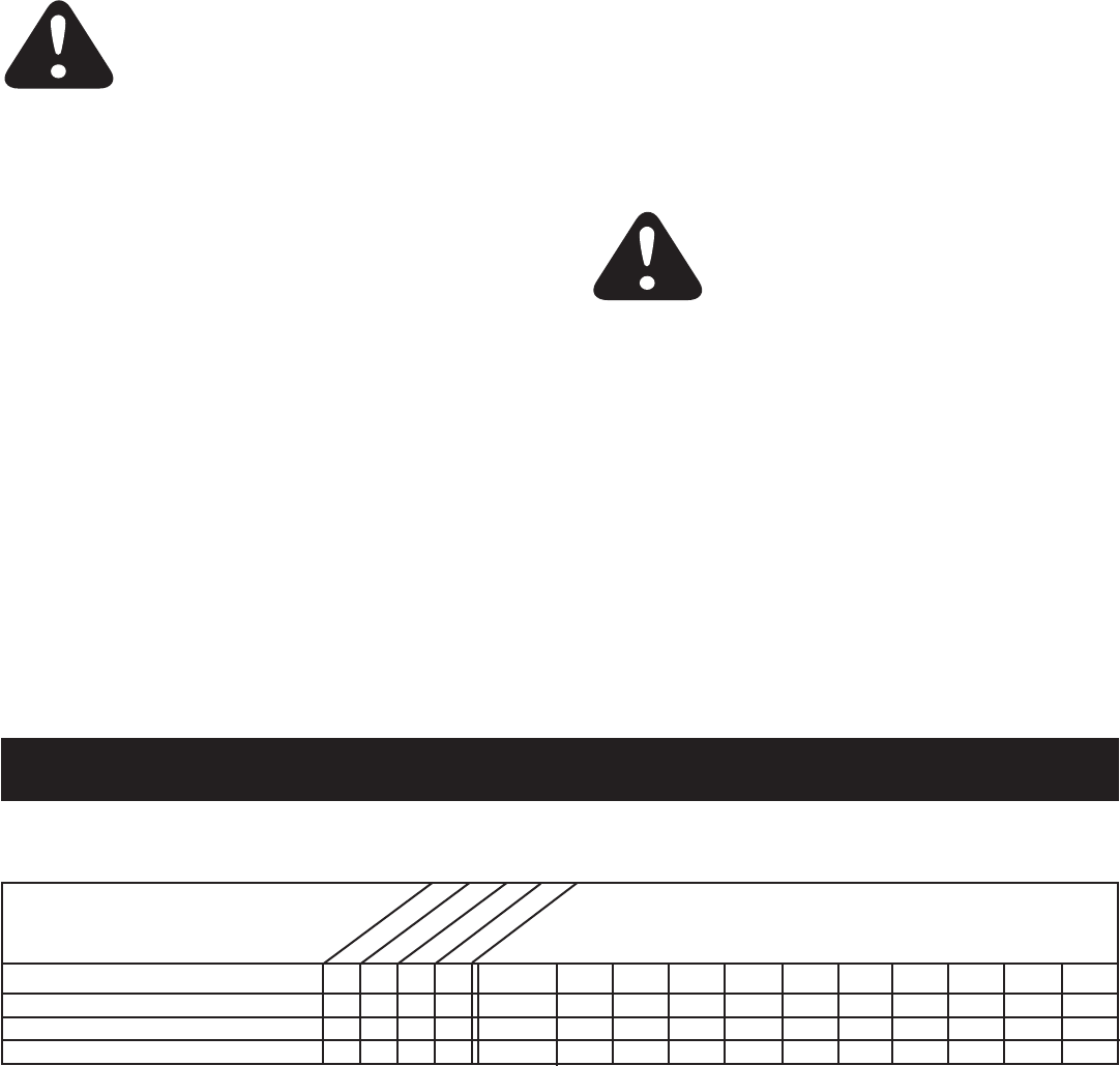
CUSTOMER RESPONSIBILITIES
• Readandfollowthemaintenancescheduleandthemaintenanceprocedureslistedinthissection.
ServiceDates
Check for loose fasteners X
Check scraper and shoes for wear X X
Cleaning X
LubricationSection X
MAINTENANCE SCHEDULE
Fill in dates as you
completeregularservice.
Before each use
After each use
Everyseason
Before storage
LUBRICATION
• Oilallpivotpointsonthesnowthrower.
• Oilthepivotpointsofthetwoidlerarmsontheclutch/
idlerassembly.
• Applypenetratingoiltothecontrolcablesofthe
discharge chute.
• Applyagoodgradeofspraylubricanttothetrigger
assemblyandthechutetiltcontrolassembly.
CAUTION: Do not operate the snow
thrower without rear wheel weights
attachedtothetractortoprovideextra
tractionandstability.
MAINTENANCE
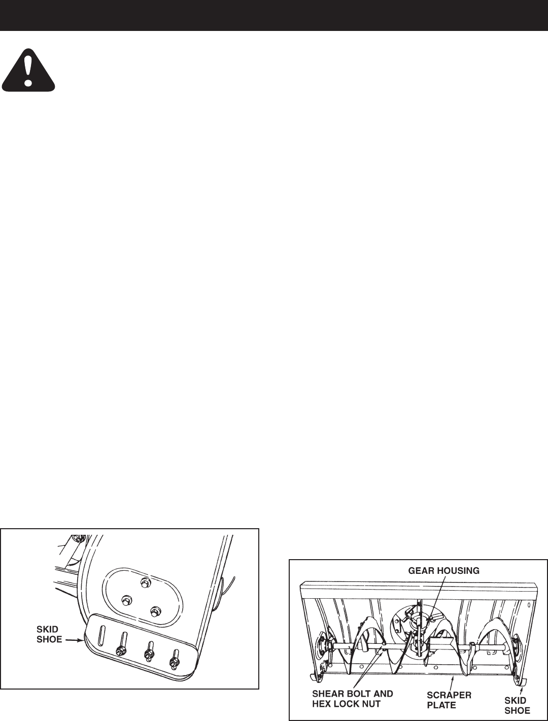
CHECK SCRAPER AND SHOES FOR WEAR
(Refer to gures 59 and 60 on page 28.)
• Thescraperplateandskidshoesonthebottomofthe
snowthroweraresubjecttowear.Topreventdamage
to the spiral auger housing, replace plate and shoes
beforewearisexcessive.
REMOVING SNOW
Snowremovalconditionsvarygreatlyfromlightuffy
snowfalltowetheavysnow.Operatinginstructionsmust
beexibletottheconditionsencountered.Theoperator
must adapt the lawn tractor and snow thrower to depth of
snow, wind direction, temperature and surface conditions.
• Beforebeginningoperation,thoroughlyinspectthe
areaofoperationandremovealldoormats,sleds,
boards,wiresandotherforeignobjects.
• Thespiralaugerspeedisdirectlyrelatedtoengine
speed.Formaximumsnowremovalanddischarge,
maintainhighenginer.p.m.(fullthrottle).Itisadvisable
to operate the lawn tractor at a slow ground speed
(1stgear)forsafeandefcientsnowremoval.
• Indeep,driftedorbankedsnowitwillbenecessaryto
use full throttle and a slow ground speed (1st gear).
Driveforwardintothesnow,depressthetractor's
clutch-brakepedalandallowthespiralaugertoclear
the snow. Repeat this method until a path is cleared.
Onthesecondpass,overlaptherstenoughtoallow
the snow thrower to handle the snow without repeated
stopping and starting of forward motion.
• Inextremelydeepsnow,raisethesnowthrowerfrom
thegroundtoremovethetoplayeranddriveforward
only until the tractors front tires reach the uncleared
bottomlayerofsnow.Depressthetractor'sclutch-
brakepedalandallowthespiralaugertoclearthe
snow.Reversethetractorandlowerthesnowthrower
totheground.Drivethetractorforwarduntilthesnow
againbecomestoodeep.Repeatingthisprocessinto
andoutofdriftswilleventuallycleareventhedeepest
of snow piles.
• Ifthesnowthrowerbecomescloggedwithsnowor
jammedwithaforeignobject,disengagethesnow
thrower immediately and shut off the tractor engine.
Unclogthesnowthrowerbeforeresumingoperation.
OPERATING TIPS
• Dischargesnowdownwindwheneverpossible.
• Tohelppreventsnowfromstickingtothesnowthrower,
allow the snow thrower to reach outdoor temperature
beforeusingit.Alightcoatofwaxmayalsobeapplied
to the inside surface of the snow thrower housing and
discharge chute.
• Usetirechainstoimprovetraction.
• Userearwheelweightstoimprovetraction.
• Beforetherstsnowfall,removeallstones,sticksand
otherobjectswhichcouldbecomehiddenbythesnow.
Permanentobstaclesshouldbemarkedforvisibility.
• Overlap each pass slightly to assure complete snow
removal.
DANGER: Shut off engine and
disengagesnowthrowerbefore
unclogging discharge chute. Unclog using
a wooden stick, not your hands.
28
SERVICE AND ADJUSTMENTS
CAUTION: Beforeservicingoradjusting
thesnowthrower,shutofftheengine,remove
thesparkplugwire(s),settheparkingbrake
andremovethekeyfromthetractorignition.
FIGURE 60
FIGURE 59
REPLACING AUGER BELT
• Disengagethetractor'sattachmentclutch.
• Lowerthesnowthrowertotheground.
• Removetheattachmentpin.
• Lockthesnowthrower'slifthandleinthedown
positiontodecreasebelttension.
• Releasethespringtensionfromtheaugerbeltidler
armonthebottomoftheclutch/idlerassembly.
• Removetheaugerdrivebeltfromtheclutch/idler
assemblyandfromthespiralaugerhousing.
• Installnewbeltovertopoflargeaugerdrivepulley
andunderthetwosideidlerpulleys.Twistthebelt1/4
turntoseatthe"V"ofthebeltinthegrooveofeach
idlerpulley.Refertogure55onpage24.
• Assemblethebeltontotheclutch/idlerassembly.
SKID SHOE ADJUSTMENT
• Theskidshoesaremountedoneachsideofthespiral
auger housing. They regulate the distance the scraper
plateisraisedabovetheplowingsurface.When
removingsnowfromagraveldrivewayoranduneven
surface,itisadvisabletokeepthescraperplateas
highabovethesurfaceaspossibletopreventpossible
damagetothespiralauger.Onblacktoporconcrete
surface, keep the scraper plate as close to the surface
aspossible.
• Raisethesnowthroweroffthegroundandplacea
blockundereachendofthescraperplate.Loosenthe
sixhexnutssecuringtheskidshoestothehousing.
Adjusttheskidshoesupordownandretightenthe
nutssecurely.Adjustbothskidshoestothesame
heighttokeepthehousingandthescraperplatelevel.
Seegure59.
LIFT RELEASE CABLE ADJUSTMENT
• Iftheliftroddoesnotlockthesnowthrowersecurely
inthetransportposition,loosentheupperhexnuton
theliftbracketafewturnsandtightenthelowerhex
nut.Refertogure48onpage22.
• Iftheliftrodfailstounlockcompletelytolowerthe
snowthrower,loosenthelowerhexnutonthelift
bracketafewturnsandtightentheupperhexnut.
Refertogure48onpage22.
CLUTCH DISENGAGEMENT ADJUSTMENT
(For tractors with engagement rod clutches only.
Not for electric clutches or cable clutches)
If the spiral auger on the snow thrower does not stop
whentheattachmentclutchleveronthetractoris
disengaged,thenadjustmentisnecessary.Proceedas
follows.Referbacktogure33onpage17.
• Placetheattachmentclutchleverinthedisengaged
position.
• Removethehairpincotterfromtheengagementrod
trunnion and lift the trunnion out of the hole in the idler
arm.
• Screwthetrunnionafewturnstowardsthefrontend
of the rod.
• Replacethetrunnionintotheholeintheidlerarmand
secure it with the hairpin cotter.
Check the operation of the snow thrower. If the spiral
augersstilldonotstop,repeattheabovestepsuntil
theaugersstopwhentheattachmentclutchleveris
placed in the disengaged position.
SPIRAL AUGERS
• Thespiralaugersaresecuredtotheaugershaftwith
twoshearboltsandnylocknuts.Ifyouhitaforeign
objectorificejamstheaugers,thesnowthroweris
designedsothattheboltswillshear.
• Iftheaugerswillnotturn,checktoseeiftheshear
boltshavesheared.Seegure60.Tworeplacement
shearboltsandnylocknutshavebeenprovidedwith
thesnowthrower.Forfutureuseorderpartnumber
42849shearboltandnumber47810nylocknut.

29
PARTS TO REMOVE AT END OF SEASON
• Removetheclutch/idlerassembly.(Thetwohanger
bracketsandthetwoshoulderboltsmaybeleft
attached to the tractor frame.)
• Removethedrivebeltfromtheenginepulley.
• Ifyoureplacedtheenginepulleykeeperonamanual
attachmentclutchtractor,reinstallthetractor'soriginal
enginepulleykeeper.Seegure33onpage17or
gure39onpage19.
• Ifyouhavearodoperatedattachmentclutch,remove
theengagementrodfromthetractor'sclutcharm.See
gure29onpage16.
• Ifafrontmountedattachmentistobeused,remove
thesideplatesfromthetractor.Besuretoassemble
boltsbackintotheemptyholesinthetractorframe.
STORAGE RECOMMENDATIONS
• Lowerthesnowthrowertotheground.
• Removethesnowthrowerfromthetractor.
• Cleanthesnowthrowerthoroughly.Washoffanysalt
depositwhichmayhavedriedonthethrowerand
housing.
• Anybaremetalthathasbecomeexposedshouldbe
paintedorcoatedwithalightoiltopreventrust.
• Storeinadryplace.
REMOVING THE SPIRAL AUGER HOUSING
• Lowerthesnowthrowertotheground.
• Removetheclevispins.Seegure54onpage24.
• Lockthesnowthrower'slifthandleinthedown
positiontodecreasebelttension.
• Releasethespringtensionfromtheaugerbeltidler
armonthebottomoftheclutch/idlerassembly.
• Removetheaugerdrivebeltfromtheclutch/idler
assembly.Seegure56onpage24.
• Pullthespiralaugerhousingassemblyoffofthe
tractor.
CAUSEPROBLEM CORRECTION
Clogged discharge chute
Spiralaugersdon'tturn
Snow thrower stalls tractor engine
TROUBLESHOOTING
STORAGE
1.UpperorlowerVbelttooloose 1.IncreasetensiononVbelt
2.UpperorlowerVbeltbroken 2.ReplaceVbelt
3.Shearboltsaresheared. 3.Replaceshearbolts
1. Tractor ground speed too fast 1. Use lower tractor gear
2. Tractor throttle set too low 2. Increase to full throttle
3. Snow too deep 3. Raise the snow thrower
4. Snow melts during contact with 4. Allow snow thrower to cool to
thesnowthrower outdoortemperaturebeforeusing
Front wheels slide instead of steering
Snowthrowerridesupoversnow
1.Objectjammedinspiralauger 1.Stopengine,disengagethesnow
thrower clutch and clear the auger
2.Hardorheavysnow 2.Increasetofullthrottleand
decrease ground speed
Not enough traction at front wheels 1. Increase scraper plate clearance
byloweringskidshoes
2. Pull down on lift handle to
increase weight on front wheels
1. Tractor ground speed too fast 1. Reduce ground speed
2. Bottom snow is icy or hard packed 2. Lower the skid shoes so that front
of skid shoe is lower than the rear
30
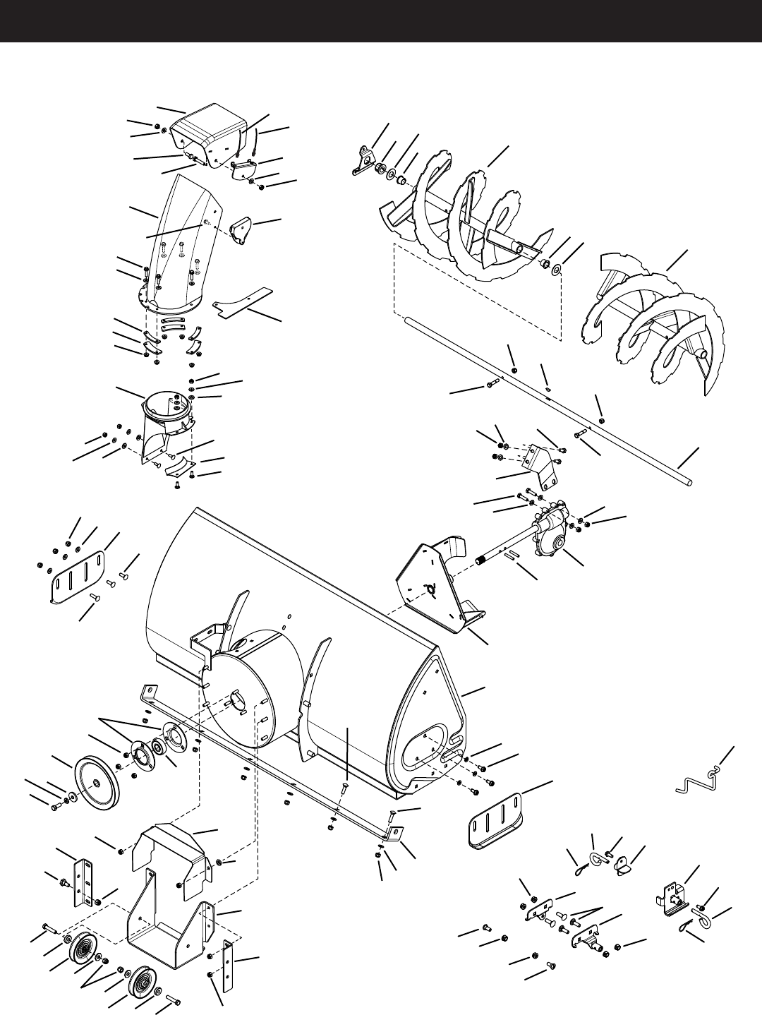
PARTS
REPAIR PARTS FOR MODEL 486.248373 42" SNOW THROWER
11
12
7
3
29
5
2
6
35
23 30 35
9
49
39
8
53
23
65
65
4
1
32
26
10
69
66
45
64
28
28
34
37
19
23
30
24
30 38
47
47
43
43
21
49
17
70
62
60
63
19
23 30 33
823
15
23
23
13 30
2330
17
23
61
55
44
36
20
22
14
27 18
36
20
68
67
30
38
22
33
21
59
31
34
14
20
25
46
48
54
41
42
18
54
40,59
40,59
18
50
51
54
54
56
52
57
50
51
58
16
16

31
REPAIR PARTS FOR MODEL 486.248373 42" SNOW THROWER
REF PART NO QTY DESCRIPTION
1 42716 2 Flange, Bearing
2 67629 1 HousingAssembly
3 71464 1 GearAssembly
4 47026 1 Pulley, V Type
5 67632 1 ImpellerAssembly
6 24773 1 Scraper Plate
7 25982 1 Shaft,AugerGearbox
8 27508 2 Bracket, Down Stop
9 24816 1 Cover,Belt
10 27510 1 Chute Reinforcement
11 67689 1 AugerAssembly,L.H.
12 67688 1 AugerAssembly,R.H.
13 43840 2 HexBolt,5/16-18x1-1/4"Lg.
14 44950 4 CarriageBolt,1/4-20x3/4"
15 HA20185 1 #61WoodruffKey
16 44326 4 CarriageBolt,5/16-18x1"Lg.
17 43080 8 CarriageBolt,5/16-18x3/4"Lg.
18 47630 8 Bolt,Self-Tap5/16"x3/4"
19 42849 2 Bolt,Shear5/16-18x1-1/2"
20 43088 10 Washer,1/4"
21 43070 2 Washer,3/8"
22 47189 4 HexNut,1/4-20Nylock
23 47810 27 HexNut,5/16-18Nylock
24 41625 2 SpiralPin,1/4"x1-1/2"Lg.
25 42846 1 Bushing
26 27505 1 Chute Adapter
27 43086 6 LockWasher,5/16"
28 43009 10 Washer,.785"x1.57"x.057"
29 27454 1 CenterBrace,Gearbox
30 43081 20 Washer,5/16"Std.Wrt.
31 47615 2 Bearing, Flange
32 42844 1 Bearing, Ball
33 43182 3 HexBolt,5/16-18x3/4"
34 42953 4 Bearing,Split,3/4"
35 24279 2 Skid Shoe
36 48015 4 Washer, Nylon
REF PART NO QTY DESCRIPTION
37 27458 2 Flange, Bearing
38 43064 2 HexLockNut,1/4-20x20
39 27502 1 Bracket, Idler
40 49933 2 Shoulder Bolt, Round Head
41 65367 1 HangerBracketAssembly,L.H.
42 65450 1 HangerBracketAssembly,R.H.
43 41576 2 HexBolt,3/8-16x1-3/4"
44 44377 1 HexBolt,3/8-24x1"
45 27584 1 Bracket,Cable
46 42836 1 Cable,ChuteControlWithClip
47 42850 2 Spacer
48 42835 1 Cable,ChuteControl
49 HA21362 4 HexNut,3/8-16Nylock
50 43038 2 Pin,PivotLock
51 43343 2 Pin,HairCotter#4(1/8")
52 43350 4 CarriageBolt,3/8-16x1"
53 27509 1 Bracket, Chute Anti-rotation
54 47572 6 HexLockNut,3/8-16Flanged
55 43003 1 LockWasher,3/8"
56 64452 1 HangerBracketAssembly,R.H.
57 64451 1 HangerBracketAssembly,L.H.
58 47043 1 Keeper, Engine Pulley
59 48106 4 Bolt, Shoulder
60 43661 6 HexBolt,1/4-20x1"
61 42828 1 Washer,
62 47598 6 HexLockNut,1/4"Flanged
63 41620 1 Chute, Upper
64 42834 1 Guide,Cable
65 47044 2 Pulley,VType4"
66 41621 1 Chute, Lower
67 43085 1 HexBolt,5/16-18x1-1/2"
68 41622 1 Screw,1/4-14x5/8"
69 27809 3 Chute Keeper
70 27810 3 Chute Spacer
42975 1 Owner'sManual
32
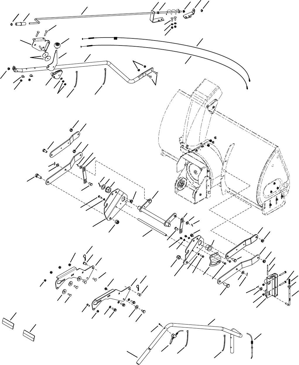
REPAIR PARTS FOR MODEL 486.248373 42" SNOW THROWER
1
6
6
3
3
4
4
4
5
6
6
2
6
6
2
8
8
8
8
9
10
10
11
12
12
13
13
10
8
14
14
16
17
17
18
18
27
25
25
31
31
32
33
36
44
63 49 53
52
44 44
41
45
39
46
47
30
43
43
48 51
50
54
55
7
58
18
63
63
63
56
66 64
62
62
40
52
19
53
65
65
59
59
5
37
34
35 59
38
59
35
15
15
10
23
24
21
26
29
22
63
20
4
28
24
6160
65
57
42

33
REPAIR PARTS FOR MODEL 486.248373 42" SNOW THROWER
REF PART NO QTY DESCRIPTION
1 64637 1 LiftShaftAssembly
2 41616 2 HexBolt,1/2-13x1"
3 41614 2 HexBolt,5/8-11x1-1/2"
4 42842 4 Pin,Clevis1/2"x78"
5 41615 2 Nut,HexLock5/8-11Thread
6 43262 6 Nut,HexLock1/2-13
7 43601 1 Washer,1.59"x1.032"x.060"
8 142 5 Pin,Cotter1/8"x3/4"
9 43093 1 Pin,Cotter1/8"x1-1/2"
10 R19171616 4 Washer,17/32"x1"
11 43350 6 CarriageBolt,3/8-16x1"
12 42939 2 Bearing, Flange With Flats
13 27753 2 Link,15.80"Long
14 27752 2 Link,11.75"Long
15 24476 2 Link,4.88"Long
16 24311 1 Rod, Spacer
17 47599 2 HexBolt,5/16-18x1"(Locking)
18 43086 4 LockWasher,5/16"
19 24820 1 Bracket, Lift
20 67784 1 Assembly,HandleLiftBracket
21 48049 1 Rod,IndexLift
22 47369 1 Pin,Spring3/16"x1-3/4"
23 42955 1 Spring, Compression
24 R19131316 2 Washer,13/32"x13/16"
25 47788 2 Reector,Rear
26 43084 2 HexBolt,5/16-18x1-3/4"
27 43182 2HexBolt,5/16-18x3/4"
28 43572 2 Washer,.343"x1.5"x.059"
29 47368 1 Pin,Spring5/16"x1-3/4"
30 44215 2 CarriageBolt,5/16-18x1-3/4"
31 43343 2 Pin,Haircotter#4(1/8")
32 25678 1 Plate, Side (R.H.)
33 25679 1 Plate, Side (L.H.)
REF PART NO QTY DESCRIPTION
34 49916 1 Tube,LiftHandle
35 49912 1 TriggerandLiftCableAssembly
36 43070 2 Washer,3/8"
37 49266 1 Screw,Oval#10-24x1-1/2"
38 44482 1 Grip, Handle
39 47027 1 Tube,CrankRodSupport
40 24393 1 Bracket, Chute Crank
41 27708 1 Bracket, Chute Crank
42 42838 1 Knob,Crank
43 44917 2 Palnut,3/8"
44 42839 3 Bushing,3/8"Plastic
45 68225 1 Assembly,ChuteCrankRod
46 27585 1 Handle, Chute Tilt
47 42833 1 Knob
48 67999 1 Assembly,ChuteTiltBracket
49 42834 1 Guide,Cable
50 42835 1 Cable,ChuteControl
51 42836 1 Cable,ChuteControlwithClip
52 43064 4 Nut,HexLock5/16-18
53 43081 3 Washer,5/16"
54 24285 1 Plate, Mounting (L.H.)
55 24284 1 Plate, Mounting (R.H.)
56 48106 2 Bolt, Shoulder
57 46584 1 Nut,Whizlock,5/16-18
58 R19172410 8 Washer,1/2"
59 726-0178 4 Tie, Nylon
60 47631 6 HexBolt,3/8-16x1"SelfTap
61 43003 6 LockWasher,3/8"
62 47572 8 Nut, Flanged Lock 3/8-16
63 47810 10 Nut,NylockHex5/16-18
64 43682 2 CarriageBolt,5/16-18x1-1/4"
65 44326 4 CarriageBolt,5/16-18x1"
66 44695 2 Washer, Bowed
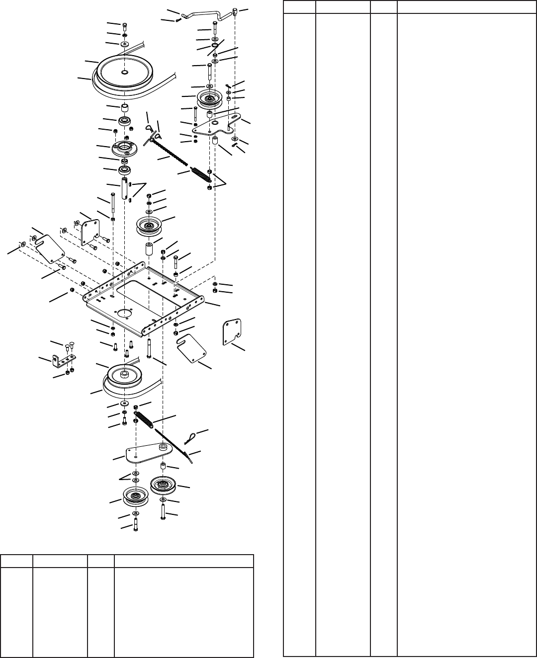
34
REPAIR PARTS FOR MODEL 486.248373 42" SNOW THROWER
REF PART NO QTY DESCRIPTION
1 43080 2 CarriageBolt,5/16-18x3/4"
2 43063 7 HexBolt,5/16-18x1"
3 43083 2 HexNut,5/16-18
4 43086 1 LockWasher,5/16"
5 43081 20 Washer,5/16"Std.Wrt.
6 26943 1 Frame, Clutch and Pulley
7 63904 1 IdlerArmAssembly
REF PART NO QTY DESCRIPTION
8 24286 1 Spacer,Pivot
9 63762 1 IdlerBracketAssembly
10 43015 1 HexNut,3/8-16
11 46981 1 Pulley,VType9"
12 43082 8 Nut,HexLock,3/8-16
13 46982 1 Pulley,VType5-1/2"
14 27582 1 Shaft
15 42830 1 Spacer
16 42831 1 Spacer
17 43003 6 LockWasher,3/8"
18 42827 2 Key
19 42829 2 Bearing, Ball
20 27781 1 Housing, Bearing
21 47810 13 HexNut,5/16-18Nylock
22 43182 4 HexBolt,5/16-18x3/4"
23 44377 2 HexBolt,3/8-24x1"
24 42828 2 Washer
25 27016 2 Front Pulley Frame Bracket
26 46989 1 Belt,VTypeDrive(55")
48138 1 Belt,VTypeDrive(56")
27 42992 1 Belt, V Type Auger
28 47044 1 Pulley,VType4"
29 47025 1 HexBolt,5/16-18x3-1/2"
30 43432 1 HexBolt,3/8-16x2-1/2"
31 43054 3 HexBolt,3/8-16x2"
32 24571 1 Spacer
33 24472 1 Spacer,Pivot
34 43070 8 Washer,3/8"
35 46959 1 Spring
36 46963 2 Chain
37 43055 1 Pin,HairCotter,3/32"
38 23727 1 Spacer
39 43088 1 Washer,1/4"
40 43343 2 Pin,HairCotter#4(1/8")
41 HA3090 2 Pin,HairCotter5/64"
42 42848 1 Trunnion
43 46948 1 Rod, Engagement
44 47620 1 Spring
45 47607 1 Spring, Torsion
46 23625 1 Spacer
47 43509 1 HexBolt,3/8-16x2-3/4"Lg.
48 47605 1 Washer,Flat3/8"
49 24558 1 CableBracket
50 49870 1 HexBolt,1/4-20x2-1/2"
51 43178 2 HexNut,1/4-20
52 43177 1 LockWasher,1/4"
53 48883 3 Pulley,Flat3-5/8"
54 25728 2 Rear Pulley Frame Bracket
55 46938 1 HexBolt,3/8-16x3-1/4"
56 25780 1 Spacer
12
3
4
2, 22
49
43
41
23
17
24
11
16
21
19
19
14
29
3
25
54
20
15
31
47
34
53
50
51
52
51
40
37
34
45
13
24
17
23
12
44
9
34
53
34
31
33
28
36
40
34
30
55
21
21
54
25
12
6
10
31
17
12
56
53
34
17
12
18
36
35
12
8
17
12
17
41
48
7
38
39
41
46
34
42
32
5
26
27
35
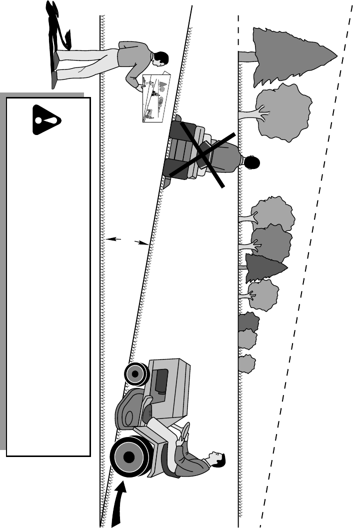
WARNING: To avoid serious injury, operate your tractor up and
down the face of slopes, never across the face. Do not operate
on slopes greater than 10 degrees. Make turns gradually to
prevent tipping or loss of control. Exercise extreme caution
when changing direction on slopes. Braking may be affected by
tractor attachment. Reduce speed on slopes.
1. Fold this page along dotted line indicated above.
2. Hold page before you so that its left edge is vertically parallel to a tree
trunk or other upright structure.
3. Sight across the fold in the direction of hill slope you want to measure.
4. Compare the angle of the fold with the slope of the hill.
ONLY RIDE UP AND DOWN HILL,
NOT ACROSS HILL
FO
LD
A
LON
G
D
O
T
TED LI
N
E
T
H
IS
I
S
A
1
0
DEG
R
E
E
SL
O
P
E
10 DEGREES MAX.
SUGGESTED GUIDE FOR SIGHTING SLOPES FOR SAFE OPERATION
OF TRACTOR WITH ATTACHMENT

® Registered Trademark /
TM
Trademark of KCD IP, LLC in the United States, or Sears Brands, LLC in other countries
® Marca Registrada /
TM
MarcadeFábricadeKCDIP,LLCenEstadosUnidos, o Sears Brands, LLC in otros países
Product questions or problems?
1-888-331-4569
Customer Care Hot Line
Get answers to questions, troubleshoot problems,
order parts, or schedule repair service.
Pararespuestasapreguntasoproblemas,yordenar
piezasopedirservicioparalareparacióndesuequipo.
To help us help you, register your product at www.craftsman.com/registration
Parapoderteayudarmejor,registratuproductoenwww.craftsman.com/registration
Join the Craftsman Club today!
Receive exclusive member benefits including special pricing and offers,
project sharing, expert advice, and SHOP YOUR WAY REWARDS!
Comomiembroexclusivo,recibediversosbeneficioscomo ofertas, precios especiales, proyectos
nuevos,consejosdeexpertosynuestroprogramadepuntos SHOP YOUR WAY REWARDS!
