Craftsman Lawn Mower Gcv160 Owners Manual
917376544 917376544 CRAFTSMAN MOWER - Manuals and Guides 1107148L View the owners manual for your CRAFTSMAN MOWER #917376544. Home:Lawn & Garden Parts:Craftsman Parts:Craftsman MOWER Manual
2015-01-05
: Craftsman Craftsman-Lawn-Mower-Gcv160-Owners-Manual-160493 craftsman-lawn-mower-gcv160-owners-manual-160493 craftsman pdf
Open the PDF directly: View PDF ![]() .
.
Page Count: 48

Owner's Manual
CRRFTSMRH°
ROTA YLAWN
160cc Honda Engine
Power-Propelled
22" Multi-Cut
MOWER
Model No.
917.376544
•EspaSol, p. 20
CAUTION:
Read and follow all
Safety Rules and Instructions
before operating this equipment
Sears Brands Management Corp., Hoffman Estates, IL 60179
Visit our Craftsman website: www.sears.com/craftsman
U.S.A.

Warranty ................................................... 2
Safety Rules .......................................... 2-4
Product Specifications .............................. 4
Assembly /Pre-Operation ........................ 6
Operation ............................................. 7-11
Maintenance Schedule ........................... 12
Maintenance ...................................... 12-15
Service and Adjustments ................... 16-17
Storage .............................................. 17-18
Troubleshooting ................................. 18-19
Repair Parts ....................................... 38-47
Sears Service .......................... Back Cover
CRAFTSMAN 2-YEAR FULL WARRANTY
For TWO YEARS from the date of purchase, this product is warranted against any
defects in material or workmanship. Defective product will receive free repair or
replacement if repair is unavailable.
For warranty coverage details to obtain free repair or replacement, visit the web site:
www.craftsman.com
This warranty covers ONLY defects in material and workmanship.
Warranty coverage does NOT include:
o Expendable parts that can wear out from normal use within the warranty
period, such as blades, blade adapters, belts, filters or spark plugs.
. Product damage resulting from user attempts at product modification or repair
or caused by product accessories.
o Repairs necessary because of accident or failure to operate or maintain this
product according to all supplied instructions.
o Preventative maintenance, or repairs necessary due to improper fuel mixture,
contaminated or stale fuel.
This warranty is void if this product is ever used while providing commercial services or
if rented to another person.
This warranty gives you specific legal rights, and you may also have other rights which
vary from state to state.
Sears Brands Management Corporation, Hoffman Estates, IL 60179
IMPORTANT: This cutting machine is capable of amputating hands and feet and throw-
ing objects. Failure to observe the following safety instructions could result in serious
injury or death.
_,Look for this symbol to point out impor-
tant safety precautions. It means
CAUTION!!! BECOME ALERT!!!
YOUR SAFETY IS INVOLVED.
_, WARNING: In order to prevent ac-
cidental starting when setting up, trans-
porting, adjusting or making repairs,
always disconnect spark plug wire and
place wire where it cannot come in contact
with plug.
_kWARNING" Engine exhaust, some of its
constituents, and certain vehicle components
contain or emit chemicals known to the State
of California to cause cancer and birth defects
or other reproductive harm.
_,WARNING" Battery posts, terminals and
related accessories contain lead and lead
compounds, chemicals known to the State
of California to cause cancer and birth
defects or other reproductive harm. Wash
hands after handling.
_i, CAUTION" Muffler and other engine
parts become extremely hot during
operation and remain hot after engine has
stopped. To avoid severe burns on contact,
stay away from these areas.
2

I. GENERAL OPERATION
, Read, understand, and follow all
instructions on the machine and in the
manual(s) before starting. Be thoroughly
familiar with the controls and the proper
use of the machine before starting.
, Do not put hands or feet near or under
rotating parts. Keep clear of the dis-
charge opening at all times.
, Only allow responsible individuals, who
are familiar with the instructions, to oper-
ate the machine.
, Clear the area of objects such as rocks,
toys, wire, bones, sticks, etc., which
could be picked up and thrown by blade.
, Be sure the area is clear of other people
before mowing. Stop machine if anyone
enters the area.
, Do not operate the mower when bare-
foot or wearing open sandals. Always
wear substantial foot wear.
, Do not pull mower backwards unless
absolutely necessary. Always look down
and behind before and while moving
backwards.
, Never direct discharged material toward
anyone. Avoid discharging material
against a wall or obstruction. Material
may richochet back toward the opera-
tor. Stop the blade when crossing gravel
surfaces.
, Do not operate the mower without
proper guards, plates, grass catcher or
other safety protective devices in place.
, See manufacturer's instructions for
proper operation and installation of
accessories. Only use accessories ap-
proved by the manufacturer.
, Stop the blade(s) when crossing gravel
drives, walks, or roads.
, Stop the engine (motor) whenever you
leave the equipment, before cleaning the
mower or unclogging the chute.
, Shut the engine (motor) off and wait until
the blade comes to complete stop before
removing grass catcher.
, Mow only in daylight or good artificial
light.
, Do not operate the machine while under
the influence of alcohol or drugs.
, Never operate machine in wet grass.
Always be sure of your footing: keep a
firm hold on the handle; walk, never run.
, Disengage the self-propelled mech-
anism or drive clutch on mowers so
equipped before starting the engine.
, If the equipment should start to vibrate
abnormally, stop the engine (motor) and
check immediately for the cause. Vibra-
tion is generally a warning of trouble.
, Always wear safety goggles or safety
glasses with side shields when operating
mower.
II. SLOPE OPERATION
Slopes are a major factor related to slip &
fall accidents which can result in severe in-
jury. All slopes require extra caution. If you
feel uneasy on a slope, do not mow it.
DO:
, Mow across the face of slopes: never
up and down. Exercise extreme caution
when changing direction on slopes.
, Remove obstacles such as rocks, tree
limbs, etc.
, Watch for holes, ruts, or bumps. Tall
grass can hide obstacles.
DO NOT:
, Do not trim near drop-offs, ditches or
embankments. The operator could lose
footing or balance.
, Do not trim excessively steep slopes.
, Do not mow on wet grass. Reduced foot-
ing could cause slipping.
III. CHILDREN
Tragic accidents can occur if the operator
is not alert to the presence of children.
Children are often attracted to the machine
and the mowing activity. Never assume
that children will remain where you last
saw them.
, Keep children out of the trimming area
and under the watchful care of another
responsible adult.
, Be alert and turn machine off if children
enter the area.
, Before and while walking backwards,
look behind and down for small children.
, Never allow children to operate the ma-
chine.
, Use extra care when approaching blind
corners, shrubs, trees, or other objects
that may obscure vision.
IV. SAFE HANDLING OF GASOLINE
Use extreme care in handling gasoline.
Gasoline is extremely flammable and the
vapors are explosive.
, Extinguish all cigarettes, cigars, pipes
and other sources of ignition.
, Use only an approved container.
, Never remove gas cap or add fuel with
the engine running. Allow engine to cool
before refueling.
, Never refuel the machine indoors.
, Never store the machine or fuel contain-
er where there is an open flame, spark
or pilot light such as a water heater or on
other appliances.
3

o Never fill containers inside a vehicle, on
a truck or trailer bed with a plastic liner.
Always place containers on the ground
away from your vehicle before filling.
o Remove gas-powered equipment from
the truck or trailer and refuel it on the
ground. If this is not possible, then
refuel such equipment with a portable
container, rather than from a gasoline
dispenser nozzle.
o Keep the nozzle in contact with the rim
of the fuel tank or container opening at
all times until fueling is complete. Do
not use a nozzle lock-open device.
o If fuel is spilled on clothing, change
clothing immediately.
o Never overfill fuel tank. Replace gas
cap and tighten securely.
V. GENERAL SERVICE
o Never run a machine inside a closed
area.
Never make adjustments or repairs with
the engine (motor) running. Disconnect
the spark plug wire, and keep the wire
away from the plug to prevent accidental
starting.
o Keep nuts and bolts, especially blade
attachment bolts, tight and keep equip-
ment in good condition.
o Never tamper with safety devices. Check
their proper operation regularly.
o Keep machine free of grass, leaves, or
other debris build-up. Clean oil or fuel
spillage. Allow machine to cool before
storing.
o Stop and inspect the equipment if you
strike an object. Repair, if necessary,
before restarting.
o Never attempt to make wheel height
adjustments while the engine is running.
o Grass catcher components are subject
to wear, damage, and deterioration,
which could expose moving parts or
allow objects to be thrown. Frequently
check components and replace with
manufacturer's recommended parts,
when necessary.
o Mower blades are sharp and can cut.
Wrap the blade(s) or wear gloves, and
use extra caution when servicing them.
o Do not change the engine governor set-
ting or overspeed the engine.
o Maintain or replace safety and instruc-
tion labels, as necessary.
&WARNING: This lawn mower is equipped with an internal combustion engine and
should not be used on or near any unimproved forest-covered, brush-covered or
grass-covered land unless the engine's exhaust system is equipped with a spark
arrester meeting applicable local or state laws (if any). If a spark arrester is used, it
should be maintained in effective working order by the operator.
In the state of California the above is required by law (Section 4442 of the California
Public Resources Code). Other states may have similar laws. Federal laws apply on
federal lands. A spark arrester for the muffler is available through your nearest Sears
Parts & Repair Center (See the REPAIR PARTS section of this manual).
Serial Number:
Date of Purchase:
Gasoline Capacity /Type: 1.0 Quarts (Unleaded Regular)
Oil Capacity: 18.5 Ounces
Oil Type (API SG-SL): SAE 30 (above 32°F) or SAE 10W-30
Spark Plug (Gap: .030") NGK BPR6ES
Valve Clearance (+ 0.04 mm): Intake: 0.015 mm; Exhaust: 0.020 mm
Blade Bolt Torque: 35-40 ft. Ibs.
o The model and serial numbers will be found on a decal on the rear of the lawn mower
housing. Record both serial number and date of purchase in space provided above.
4

Repair Protection Agreements
Congratulations on making a smart pur-
chase. Your new Craftsman® product is
designed and manufactured for years of
dependable operation. But like all prod-
ucts, it may require repair from time to
time. That's when having a Repair Protec-
tion Agreement can save you money and
aggravation.
Purchase a Repair Protection Agreement
now and protect yourself from unexpected
hassle and expense.
Here's what's included in the Agreement:
, Expert service by our 12,000 profe-
sional repair specialists.
,Unlimited service and no charge for
parts and labor on all covered repairs.
,Product replacement if your covered
product can't be fixed.
, Discount of 10% from regular price of
service and service-related parts not
covered by the agreement; also, 10%
off regular price of preventive mainte-
nance check.
, Fast help by phone- phone sup-
port from a Sears representative on
products requiring in-home repair, plus
convenient repair scheduling.
Once you purchase the Agreement, a
simple phone call is all that it takes for you
to schedule service. You can call anytime
day or night, or schedule a service ap-
pointment online.
Sears has over 12,000 professional repair
specialists, who have access to over 4.5
million quality parts and accessories.
That's the kind of professionalism you can
count on to help prolong the life of your
new purchase for years to come. Purchase
your Repair Protection Agreement today!
Some limitations and exclusions apply.
For prices and additional information
call 1-800-827-6655.
Sears installation Service
For Sears professional installation of home
appliances, garage door openers, water
heaters, and other major home items, in
the U.S.A. call 1-800-4-MY=HOME®.
These accessories were available when this lawn mower was produced. They are not
shipped with your mower. They are also available at most Sears retail outlets and
service centers. Some of these accessories may not apply to your lawn mower.
LAWN MOWER PERFORMANCE
CLIPPING
DEFLECTORS
FOR
REAR DISCHARGE
LAWN MOWERS
GRASS CATCHERS
FOR
REAR DISCHARGE
LAWN MOWERS
STABILIZER
GAS
CANS
GRASS CATCHERS
FOR
SIDE DISCHARGE
LAWN MOWERS
LAWN MOWER MAINTENANCE
MUFFLERS
BELTS BLADES BLADE ADAPTERS
AIR FILTERS
WHEELS
SPARK PLUGS
ENGINE OIL
5

Read these instructions and this manual in its entirety before you attempt to assemble
or operate your new lawn mower.
IMPORTANT: This lawn mower is shipped WITHOUT OIL OR GASOLINE in the engine.
Your new lawn mower has been assembled at the factory with the exception of those parts
left unassembled for shipping purposes. To ensure safe and proper operation of your lawn
mower, all parts and hardware you assemble must be tightened securely. Use the correct
tools as necessary to ensure proper tightness. All parts such as nuts, washers, bolts, etc.,
necessary to complete the assembly have been placed in the parts bag.
TO REMOVE MOWER FROM CARTON
1. Remove loose parts included with mower.
2. Cut down two end corners of carton
and lay end panel down flat.
3. Remove aNpacking materials except
padding between upper and lower
handle and padding holding operator
presence control bar to upper handle.
4. Roll lawn mower out of carton and
check carton thoroughly for additional
loose parts.
HOW TO SET UP YOUR MOWER
TO UNFOLD HANDLE
IMPORTANT: Unfold handle carefully so
as not to pinch or damage control cables.
1. Raise handles until lower handle sec-
tion locks into place in mowing position.
2. Remove protective padding, raise up-
per handle section into place on lower
handle and tighten both handle knobs.
3. Remove handle padding holding operator
presence control bar to upper handle.
Your lawn mower handle can be adjusted
for your mowing comfort. Refer to "AD-
JUST HANDLE" in the Service and Adjust-
ments section of this manual.
Operator MOWING
POSITION
control bar
Handle
bracket
Knob
Bolt
TO ASSEMBLE GRASS CATCHER
1. Put grass catcher frame into grass bag
with rigid part of bag on the bottom.
Make sure the frame handle is outside
of the bag top.
2. Slip vinyl bindings over frame.
NOTE: If vinyl bindings are too stiff, hold
them in warm water for a few minutes. If
bag gets wet, let it dry before using.
UP
Handle
knob
Lower handle
Vinyl Frame
bindings opening
6
TO INSTALL ATTACHMENTS
Your lawn mower was shipped ready to be
used as a mulcher. To convert mower to
bagging or discharging, see "TO CON-
VERT MOWER" in the Operation section
of this manual.

KNOW YOUR LAWN MOWER
READ THIS OWNER'S MANUAL AND ALL SAFETY RULES BEFORE OPERATING
YOUR LAWN MOWER. Compare the illustrations with your lawn mower to familiarize
yourself with the location of various controls and adjustments. Save this manual for
future reference.
These symbols may appear on your lawn mower or in literature supplied with the
product. Learn and understand their meaning.
CAUTION ENGINE ENGINE FAST SLOW CHOKE FUEL OIL DANGER, KEEP HANDS
OR WARNING ON OFF AND FEET AWAY
Operator presence control bar
Drive control levers
Handle knobs
Gasoline filler cap
Starter
handle
Fuel valve lever
plug
Grass
catcher Air filter
Engine oil cap
with dipstick
Wheel adjuster
(on each wheel)
Muffler _ .............
Mulcher door Drive cover
Housing
IMPORTANT: This lawn mower is shipped
WITHOUT OIL OR GASOLINE in the engine.
NOTE" Gasoline containing up to 10% ethanol (El0) is acceptable for use in this machine.
The use of any gasoline exceeding 10% ethanol (El0) will void the product warranty.
MEETS CPSC SAFETY REQUIREMENTS
Sears rotary walk-behind power lawn mowers conform to the safety standards of the
American National Standards Institute and the U.S. Consumer Product Safety Commis-
sion. ,&WARNING" The blade turns when the engine is running.
Operator presence control bar - must Mulcher door - allows conversion to
be held down to the handle to start the discharging or bagging operation.
engine. Release to stop the engine. Drive control levers - used to engage
Starter handle - used for starting engine. 7 power-propelled forward motion of mower.

The operation of any lawn
SAFETVG'ASSESmower can result in foreign
objectsthrown intothe eyes,
whichcanresultinsevereeye
damage.Alwayswear safety
glasses or eyeshieldswhile operatingyour
lawnmower or performingany adjustments
or repairs.We recommendastandardsafety
glasses or wide vision safety mask worn
over spectacles.
HOW TO USE YOUR LAWN MOWER
ENGINE SPEED
Engine speed was set at the factory for
optimum performance. It is not adjustable.
ENGINE ZONE CONTROL
_k.CAUTION" Federal regulations require
an engine control to be installed on this
lawn mower in order to minimize the risk
of blade contact injury. Do not under
any circumstances attempt to defeat the
function of the operator control. The blade
turns when the engine is running.
o Your lawn mower is equipped with an
operator presence control bar which
requires the operator to be positioned
behind the lawn mower handle to start
and operate the lawn mower.
DRIVE CONTROL
o Self-propelling is controlled by holding
the operator presence control bar down
to the handle and pulling either drive
control lever rearward to the handle.
The further toward the handle a lever is
pulled, the faster the unit will travel.
o Forward motion will stop when either
the operator presence control bar or a
drive control lever are released. To stop
forward motion without stopping engine,
release a drive control lever only. Hold
operator presence control bar down
against handle to continue mowing
without self-propelling.
NOTE: If after releasing the drive control
the mower will not roll backwards, push
the mower forward slightly to disengage
drive wheels.
Operator presence control bar
rive
control levers
handle to lift the front wheels off the
ground while turning lawn mower.
DRIVE CONTROL ADJUSTMENT
Over time, the drive control system may
become "loose", resulting in decreased
speed. There is a turnbuckle on the drive
control housing to increase tension on the
drive cable. Proceed as follows:
1. Turn unit off and disconnect spark plug
wire from spark plug.
2. Rotate turnbuckle on drive control to
increase drive speed.
3. Operate mower to test drive speed.
Readjust as required.
4. If condition fails to improve after the
above steps (forward speed remains
the same), your drive belt is worn and
should be replaced.
Adjustment
turnbuckle
TO ADJUST CUTTING HEIGHT
Raise wheels for low cut and lower wheels
for high cut, adjust cutting height to suit
your requirements. Medium position is
best for most lawns.
o To change cutting height, pull up on
adjuster lever, move wheel up or down
to suit your requirements and release
adjuster lever. Be sure all wheels are in
the same setting.
NOTE: Adjuster is properly positioned
when lever inserts into hole in plate.
LEVER BACKWARD
TO LOWER MOWER
Lever
LEVER
FORWARD
TO RAISE MOWER
TO ENGAGE
DRIVE CONTROL DRIVE CONTROL
DISENGAGED
o To keep drive control engaged when
turning corners, push down on the 8

TO CONVERT MOWER
Your lawn mower was shipped ready to be
used as a mulcher. To convert to bagging
or discharging:
REAR BAGGING
,Lift rear door of the lawn mower and
place the grass catcher frame hooks
onto the grass bag brackets.
,To convert to mulching or discharging
operation, remove grass catcher and
close rear door.
door
Grass bag
bracket Grass
catcher
"'-.. handle
Grass
frame hook
NOTE: Rear door will remain open until
operator presence control bar is held
down to the handle.
ACAUTION: Do NOT force rear door to
close. Serious damage to your mower
could result.
SIDE DISCHARGING
,Rear door must be closed.
,Open mulcher door and install dis-
charge deflector under door as shown.
,Mower is now ready for discharging
operation.
,To convert to mulching or bagging
operation, discharge deflector must be
removed and mulcher door must be
closed and locked.
\
\
Open I
mulcher door I
Discharge
deflector
\
SIMPLE STEPS TO REMEMBER WHEN
CONVERTING YOUR LAWN MOWER
FOR MULCHING -
1. Rear door closed.
2. Mulcher door closed and locked.
FOR REAR BAGGING -
1. Grass catcher installed.
2. Mulcher door closed and locked.
FOR SIDE DISCHARGING -
1. Rear door closed.
2. Discharge deflector installed.
ACAUTION: Do not run your lawn mow-
er without rear door closed or approved
grass catcher in place. Never attempt to
operate the lawn mower with the rear door
removed or propped open.
9
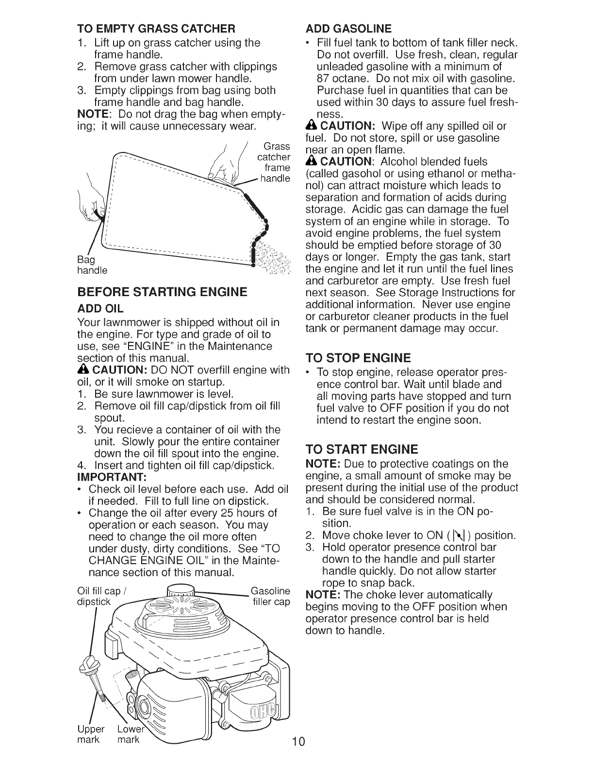
TO EMPTY GRASS CATCHER
1. Lift up on grass catcher using the
frame handle.
2. Remove grass catcher with clippings
from under lawn mower handle.
3. Empty clippings from bag using both
frame handle and bag handle.
NOTE: Do not drag the bag when empty-
ing; it will cause unnecessary wear.
G rass
catcher
frame
Bag
handle
BEFORE STARTING ENGINE
ADD OIL
Your lawnmower is shipped without oil in
the engine. For type and grade of oil to
use, see "ENGINE" in the Maintenance
section of this manual.
& CAUTION: DO NOT overfill engine with
oil, or it will smoke on startup.
1. Be sure lawnmower is level.
2. Remove oil fill cap/dipstick from oil fill
spout.
3. You recieve a container of oil with the
unit. Slowly pour the entire container
down the oil fill spout into the engine.
4. Insert and tighten oil fill cap/dipstick.
IMPORTANT:
*Check oil level before each use. Add oil
if needed. Fill to full line on dipstick.
,Change the oil after every 25 hours of
operation or each season. You may
need to change the oil more often
under dusty, dirty conditions. See "TO
CHANGE ENGINE OIL" in the Mainte-
nance section of this manual.
Oil fill cap /Gasoline
dips filler cap
ADD GASOLINE
*Fill fuel tank to bottom of tank filler neck.
Do not overfill. Use fresh, clean, regular
unleaded gasoline with a minimum of
87 octane. Do not mix oil with gasoline.
Purchase fuel in quantities that can be
used within 30 days to assure fuel fresh-
ness.
CAUTION: Wipe off any spilled oil or
fuel. Do not store, spill or use gasoline
near an open flame.
,A CAUTION: Alcohol blended fuels
(called gasohol or using ethanol or metha-
nol) can attract moisture which leads to
separation and formation of acids during
storage. Acidic gas can damage the fuel
system of an engine while in storage. To
avoid engine problems, the fuel system
should be emptied before storage of 30
days or longer. Empty the gas tank, start
the engine and let it run until the fuel lines
and carburetor are empty. Use fresh fuel
next season. See Storage Instructions for
additional information. Never use engine
or carburetor cleaner products in the fuel
tank or permanent damage may occur.
TO STOP ENGINE
*To stop engine, release operator pres-
ence control bar. Wait until blade and
all moving parts have stopped and turn
fuel valve to OFF position if you do not
intend to restart the engine soon.
TO START ENGINE
NOTE: Due to protective coatings on the
engine, a small amount of smoke may be
present during the initial use of the product
and should be considered normal.
1. Be sure fuel valve is in the ON po-
sition.
2. Move choke lever to ON (N) position.
3. Hold operator presence control bar
down to the handle and pull starter
handle quickly. Do not allow starter
rope to snap back.
NOTE: The choke lever automatically
begins moving to the OFF position when
operator presence control bar is held
down to handle.
Upper Lowe
mark mark 10

OFF lever
Fuel valve lever
MOWING TiPS
,_ CAUTION: Do not use de-thatcher
blade attachments on your mower. Such
attachments are hazardous, will damage
your mower and could void your warranty.
o Under certain conditions, such as very
tall grass, it may be necessary to raise
the height of cut to reduce pushing effort
and to keep from overloading the engine
and leaving clumps of grass clippings.
It may also be necessary to reduce
ground speed and/or run the lawn
mower over the area a second time.
o For extremely heavy cutting, reduce the
width of cut by overlapping previously
cut path and mow slowly.
. For better grass bagging and most cut-
ting conditions, the engine speed should
be set in the FAST position.
. Pores in cloth grass catchers can
become filled with dirt and dust with use
and catchers will collect less grass. To
prevent this, regularly hose catcher off
with water and let dry before using.
o Keep top of engine around starter clear
and clean of grass clippings and chaff.
This will help engine air flow and extend
engine life.
MULCHING MOWING TiPS
IMPORTANT: For best performance,
keep mower housing free of built-up
grass and trash. See "CLEANING" in the
Maintenance section of this manual.
. The special mulching blade will recut
the grass clippings many times and
reduce them in size so that as they fall
onto the lawn they will disperse into
the grass and not be noticed. Also, the
mulched grass will biodegrade quickly
to provide nutrients for the lawn. Always
mulch with your highest engine (blade)
speed as this will provide the best recut-
ting action of the blades.
. Avoid cutting your lawn when it is wet.
Wet grass tends to form clumps and
interferes with the mulching action. The
best time to mow your lawn is the early
afternoon. At this time the grass has
dried, yet the newly cut area will not be
exposed to direct sunlight.
o For best results, adjust the lawn mower
cutting height so that the lawn mower
cuts off only the top one-third of the
grass blades. If the lawn is overgrown it
will be necessary to raise the height of
cut to reduce pushing effort and to keep
from overloading the engine and leaving
clumps of mulched grass. For extremely
heavy grass, reduce your width of cut
by overlapping previously cut path and
mow slowly.
MAX 1/3
o Certain types of grass and grass
conditions may require that an area be
mulched a second time to completely
hide the clippings. When doing a sec-
ond cut, mow across (perpendicular) to
the first cut path.
o Change your cutting pattern from week
to week. Mow north to south one week
then change to east to west the next
week. This will help prevent matting and
graining of the lawn.
11
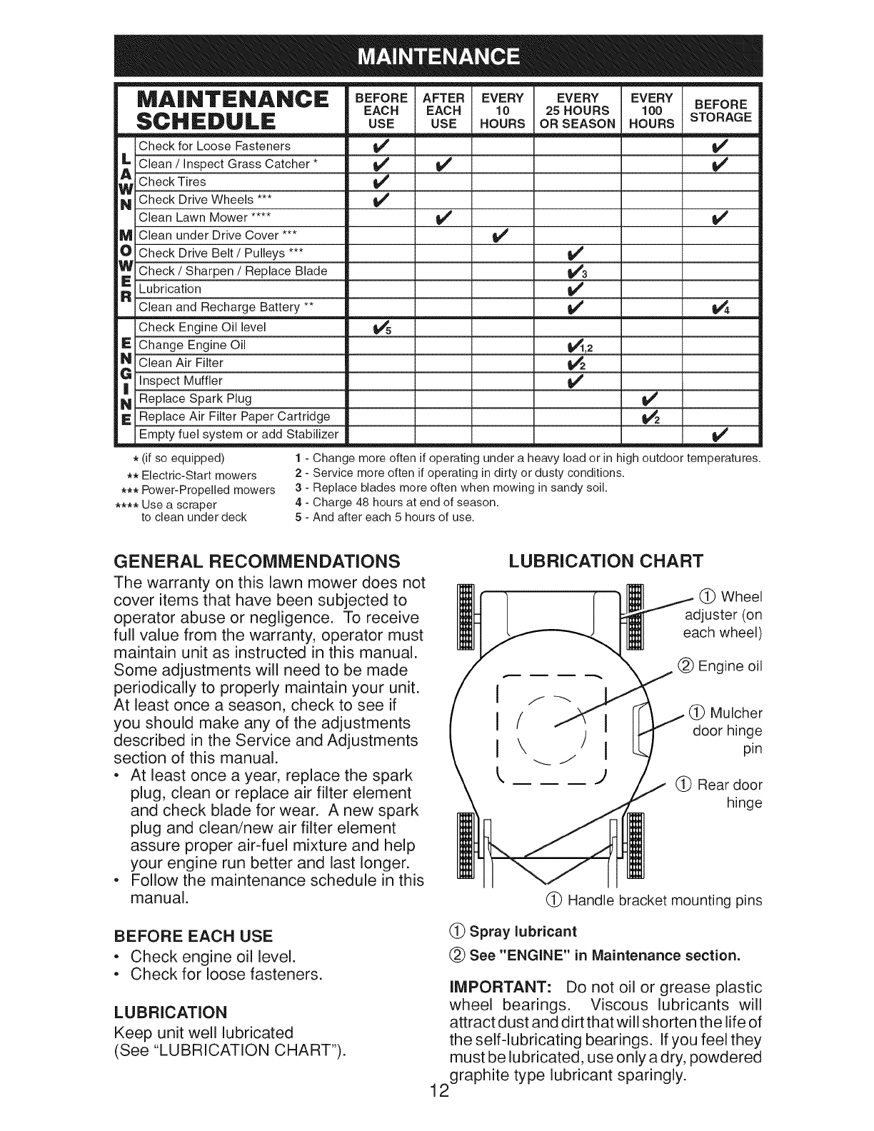
MAINTENANCE BEFOREAFTEREVERY
EACH EACH 10
SCHEDULE USE USE HOURS
Check for Loose Fasteners 1_#
_ lean /Inspect Grass Catcher *
Check Tires
_ Check Drive Wheels 1_
EVERY EVERY BEFORE
25HOURS 100 STORAGE
OR SEASON HOURS
Clean Lawn Mower ....
M Clean under Drive Cover ***
OCheck Drive Belt /Pulleys ***
W Check /Sharpen /Replace Blade
_ Lubrication
Clean and Recharge Battery **
-- Check Engine Oil level
I_ Change Engine Oil
N Clean Air Filter
_ Inspect Muffler
N Replace Spark Plug
IE Replace Air Filter Paper Cartridge
Empty fuel system or add Stabilizer
i,/
t/3
v'
_,2
_4
_4
v"
_4
* (if so equipped)
** Electric-Start mowers
*** Power-Propelled mowers
**** Use a scraper
to clean under deck
1-Change more often if operating under a heavy load or in high outdoor temperatures.
2 - Service more often if operating in dirty or dusty conditions.
3 - Replace blades more often when mowing in sandy soil.
4 - Charge 48 hours at end of season.
5 - And after each 5 hours of use.
GENERAL RECOMMENDATIONS
The warranty on this lawn mower does not
cover items that have been subjected to
operator abuse or negligence. To receive
full value from the warranty, operator must
maintain unit as instructed in this manual.
Some adjustments will need to be made
periodically to properly maintain your unit.
At least once a season, check to see if
you should make any of the adjustments
described in the Service and Adjustments
section of this manual.
oAt least once a year, replace the spark
plug, clean or replace air filter element
and check blade for wear. A new spark
plug and clean/new air filter element
assure proper air-fuel mixture and help
your engine run better and last longer.
oFollow the maintenance schedule in this
manual.
BEFORE EACH USE
oCheck engine oil level.
oCheck for loose fasteners.
LUBRICATION
Keep unit well lubricated
(See "LUBRICATION CHART").
LUBRICATION CHART
(_ Wheel
adjuster (on
each wheel)
(_) Engine oil
(_ Mulcher
door hinge
pin
(_ Rear door
hinge
(_ Handle bracket mounting pins
(_ Spray lubricant
(_) See "ENGINE" in Maintenance section.
IMPORTANT: Do not oil or grease plastic
wheel bearings. Viscous lubricants will
attract dust and dirt that will shorten the life of
the self-lubricating bearings. If you feel they
must be lubricated, use only a dry, powdered
2graphite type lubricant sparingly.
1
LAWN MOWER
Always observe safety rules when per-
forming any maintenance.
TIRES
,Keep tires free of gasoline, oil, or insect
control chemicals which can harm rubber.
,Avoid stumps, stones, deep ruts, sharp
objects and other hazards that may
cause tire damage.
DRIVE WHEELS
Check front drive wheels each time before
you mow to be sure they move freely.
The wheels not turning freely means trash,
grass cuttings, etc. are in the drive wheel area
and must be cleaned to free drive wheels.
If necessary to clean the drive wheels, be
sure to clean both front wheels.
1. Remove hubcaps, Iocknuts & washers.
2. Remove wheels from wheel adjusters.
3. Remove any trash or grass cuttings
from inside the dust cover, pinion and/
or drive wheel gear teeth.
4. Put wheels back in place.
NOTE: If after cleaning, the drive wheels
do not turn freely, contact a Sears or other
qualified service center.
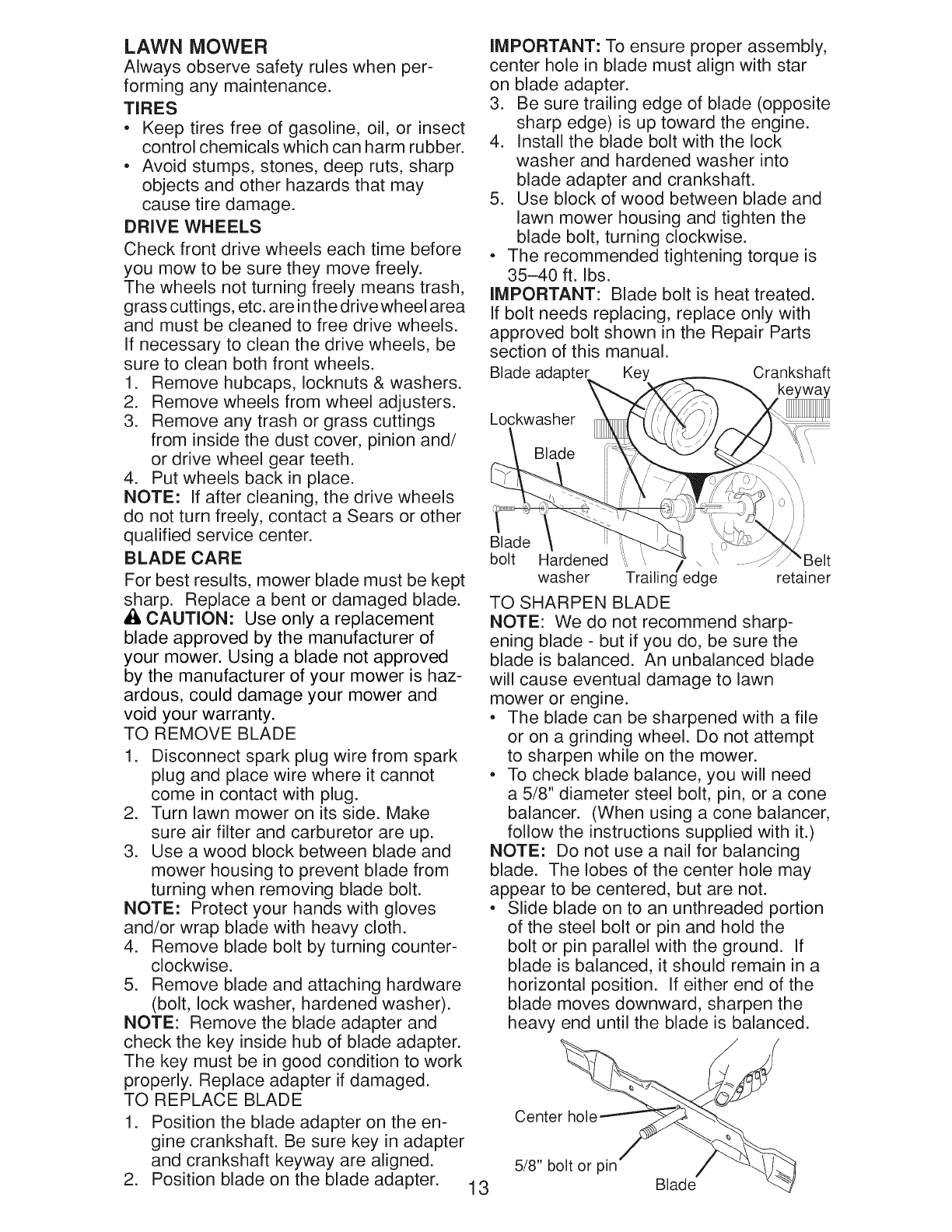
BLADE CARE
For best results, mower blade must be kept
sharp. Replace a bent or damaged blade.
A CAUTION" Use only a replacement
blade approved by the manufacturer of
your mower. Using a blade not approved
by the manufacturer of your mower is haz-
ardous, could damage your mower and
void your warranty.
TO REMOVE BLADE
1. Disconnect spark plug wire from spark
plug and place wire where it cannot
come in contact with plug.
2. Turn lawn mower on its side. Make
sure air filter and carburetor are up.
3. Use a wood block between blade and
mower housing to prevent blade from
turning when removing blade bolt.
NOTE: Protect your hands with gloves
and/or wrap blade with heavy cloth.
4. Remove blade bolt by turning counter-
clockwise.
5. Remove blade and attaching hardware
(bolt, lock washer, hardened washer).
NOTE: Remove the blade adapter and
check the key inside hub of blade adapter.
The key must be in good condition to work
properly. Replace adapter if damaged.
TO REPLACE BLADE
1. Position the blade adapter on the en-
gine crankshaft. Be sure key in adapter
and crankshaft keyway are aligned.
2. Position blade on the blade adapter. 13
IMPORTANT: To ensure proper assembly,
center hole in blade must align with star
on blade adapter.
3. Be sure trailing edge of blade (opposite
sharp edge) is up toward the engine.
4. Install the blade bolt with the lock
washer and hardened washer into
blade adapter and crankshaft.
5. Use block of wood between blade and
lawn mower housing and tighten the
blade bolt, turning clockwise.
,The recommended tightening torque is
35-40 ft. Ibs.
IMPORTANT: Blade bolt is heat treated.
If bolt needs replacing, replace only with
approved bolt shown in the Repair Parts
section of this manual.
Blade adapter Key Crankshaft
Lockwasher
Blade \
Blade
bolt Hardened
washer Trailin/edge retainer
TO SHARPEN BLADE
NOTE: We do not recommend sharp-
ening blade - but if you do, be sure the
blade is balanced. An unbalanced blade
will cause eventual damage to lawn
mower or engine.
,The blade can be sharpened with a file
or on a grinding wheel. Do not attempt
to sharpen while on the mower.
,To check blade balance, you will need
a 5/8" diameter steel bolt, pin, or a cone
balancer. (When using a cone balancer,
follow the instructions supplied with it.)
NOTE: Do not use a nail for balancing
blade. The lobes of the center hole may
appear to be centered, but are not.
,Slide blade on to an unthreaded portion
of the steel bolt or pin and hold the
bolt or pin parallel with the ground. If
blade is balanced, it should remain in a
horizontal position. If either end of the
blade moves downward, sharpen the
heavy end until the blade is balanced.
Center hole
5/8" bolt or pin Blade

GRASS CATCHER
o The grass catcher may be hosed with
water, but must be dry when used.
o Check your grass catcher often for dam-
age or deterioration. Through normal
use it will wear. If catcher needs replac-
ing, replace only with approved replace-
ment catcher shown in the Repair Parts
section of this manual. Give the lawn
mower model number when ordering.
GEAR CASE
o To keep your drive system working
properly, the gear case and area around
the drive should be kept clean and free
of trash build-up. Clean under the drive
cover twice a season.
o The gear case is filled with lubricant to the
proper level at the factory. The only time
the lubricant needs attention is if service
has been performed on the gear case.
1. Disconnect spark plug wire from spark
plug and place wire where it cannot
come in contact with plug.
2. Remove oil fill cap/dipstick; lay aside
on a clean surface.
3. Tip lawn mower on its side as shown
and drain oil into a suitable container.
Rock lawn mower back and forth to re-
move any oil trapped inside of engine.
ENGINE
Maintenance, repair, or replacement of the 4.
emission control devices and systems, which
are being done at the customers expense, 5.
may be performed by any non-road engine
repair establishment or individual. Warranty 6.
repairs must be performed by an authorized
engine manufacturer's service outlet.
LUBRICATION
Use only high quality detergent oil rated
with API service classification SG-SL.
Select the oil's SAE viscosity grade
according to your expected operating
temperature.
SAE VISCOSITY GRADES
4O
°F -20 0 30 32 40 60 80 100
°c -_o -2; -_; ; 1; _o _o
TEMPERATURE RANGE ANTICIPATED BEFORE NEXT OIL CHANGE
NOTE: Multi-viscosity oils (5W30, 10W30
etc.) improve starting in cold weather, and
you should check your engine oil level fre-
quently to avoid possible engine damage
from running low on oil.
Change the oil after every 25 hours of
operation or at least once a year if the
lawn mower is not used for 25 hours in
one year.
Check the crankcase oil level before
starting the engine and after each five (5)
hours of continuous use. Tighten oil plug
securely each time you check the oil level.
TO CHANGE ENGINE OIL
NOTE: Before tipping lawn mower to drain
oil, empty fuel tank by running engine until
Wipe off any spilled oil from lawn
mower or side of engine.
Fill engine with oil. Slowly pour oil
down the oil fill spout into the engine.
Wait one minute to allow oil to settle.
Use guage on oil fill cap/dipstick for
checking level. Insert dipstick into
the tube and rest the oil fill cap on the
tube. DO NOT thread the cap into the
tube when taking reading.
Oil fill cap /
dipstick
Upper _
mark
7. Continue adding small amounts of
oil and rechecking the dipstick until it
reads full. DO NOT overfill, or engine
will smoke on startup.
8. Always be sure to retighten oil fill cap/
dipstick before starting engine.
9. Reconnect spark plug wire to spark
plug.
AIR FILTER
Your engine will not run properly and may
be damaged by using a dirty air filter.
Replace the air filter every 100 hours of
operation or every season, whichever oc-
curs first. Service air cleaner more often
under dusty conditions.
fuel tank is empty. 14
TO CLEAN AIR FILTER
1. Remove cover.
2. Carefully remove cartridge.
3. Clean by gently tapping on a flat sur-
face. If very dirty, replace cartridge.
_;I,CAUTION: Petroleum solvents, such
as kerosene, are not to be used to clean
cartridge. They may cause deterioration
of the cartridge. Do not oil cartridge. Do
not use pressurized air to clean or dry
cartridge.
4. Install cartridge, then replace cover.
Tab
Cartridge
Filter cove
MUFFLER
Inspect and replace corroded muffler as it
could create a fire hazard and/or damage.
SPARK PLUG
Replace spark plug at the beginning of
each mowing season or after every 100
hours of operation, whichever occurs
first. Spark plug type and gap setting
are shown in the "PRODUCT SPECIFIC-
ATIONS" section of this manual.
CLEANING
IMPORTANT: For best performance,
keep mower housing free of built-grass
and trash. Clean the underside of your
mower after each use.
,ACAUTION" Disconnect spark plug wire
from spark plug and place wire where it
cannot come in contact with plug.
, Clean the underside of your lawn mower
by scraping to remove build-up of grass
and trash.
, Clean engine often to keep trash from
accumulating. A clogged engine runs
hotter and shortens engine life.
, Keep finished surfaces and wheels free
of all gasoline, oil, etc.
, We do not recommend using a garden
hose to clean lawn mower unless the
electrical system, muffler, air filter and
carburetor are covered to keep water
out. Water in engine can result in short-
ened engine life.
WATER WASHOUT FEATURE
Your lawn mower is equipped with a fitting
that allows quick and easy cleaning of
the underside of the housing. To use this
feature, proceed as follows:
1. Move lawn mower to an area of cut
grass or another hard surface.
NOTE: Water, grass and other debris will
drain from beneath the mower housing
during the washout process.
2. Remove grass catcher and discharge
chute assembly from lawn mower.
3. Close mulcher door (if equipped).
4. Connect a garden hose to the fitting
where shown.
IMPORTANT: Be sure the garden hose is
not routed under the lawn mower housing
or entangled in the wheels.
5. Turn on water supply and check for
leaks at the fitting.
If no leaks are present, start engine (as
described in the Operation section of this
manual) and let engine run until the under-
side of the lawn mower is clean.
Al_WARNING: Do not engage the drive
system during the washout process.
6. Shut off the engine.
7. Shut off water supply and remove hose
from fitting.
CAUTION: Do not remove hose from
fitting while engine is running. Water in
engine can result in shortened engine life.
8. Start engine (as described in the Op-
eration section of this manual) and let
engine run for a full minute to remove
excess water from mower.
Hose
Fitting
15
CLEAN UNDER DRIVE COVER
Clean under drive cover at least twice a
season. Scrape underside of cover with
putty knife or similar tool to remove any
build-up of trash or grass on underside
of drive cover.

• ILWARNING: To avoid serious injury, before performing any service and adjustments:
1. Release control bar and stop engine.
2. Make sure the blade and all moving parts have completely stopped.
3. Disconnect spark plug wire from spark plug and place wire where it cannot come in
contact with plug.
LAWN MOWER
TO ADJUST CUTTING HEIGHT
See "TO ADJUST CUTTING HEIGHT" in
the Operation section of this manual.
NOTE: Always use factory approved belt
to assure proper fit and long life.
Blade adapter Key Crankshaft
REAR DEFLECTOR
The rear deflector, attached between the
rear wheels of your mower, is provided to
minimize the possibility that objects will
be thrown out of the rear of the mower
into the operator mowing position. If the
deflector becomes damaged, it should be
replaced.
TO REMOVE DRIVE BELT
1. Remove drive cover and belt keeper.
2. Remove belt from gearcase pulley.
3. Turn lawn mower on its side with air
filter and carburetor up.
4. Remove blade and blade adapter.
5. Remove belt from engine pulley.
Drive
cover
\
Gearcase
pulley
Belt
)er
Lockwasher
Blade
Blade
,,,, _,
bolt Hardened \ '\
washer Trailing/edge retainer
TO ADJUST HANDLE
The handle on your lawn mower has three
(3) height positions - adjust to height that
suits you.
1. Remove knob and carriage bolt on one
side of the lower handle.
2. While holding handle assembly,
remove knob and carriage bolt from
opposite side, align hole in handle with
desired hole in handle bracket and
reassemble bolt and knob and tighten
securely.
3. Align opposite side of handle with
same positioning hole and secure with
bolt and knob.
Handle
bracket
Knob
/Belt Bolt
TO REPLACE DRIVE BELT
1. Place new drive belt on engine pulley,
inside tabs of belt retainer.
2. Route the other end of the new drive
belt through hole in housing.
3. Reinstall blade adapter and blade.
4. Return mower to upright position.
5. Install new belt on gearcase pulley.
6. Reinstall belt keeper and drive cover. 16

ENGINE
Maintenance, repair, or replacement of the
emission control devices and systems, which
are being done at the customers expense,
may be performed by any non-road engine
repair establishment or individual. Warranty
repairs must be performed by an authorized
engine manufacturer's service outlet.
ENGINE SPEED
Your engine speed has been factory set.
Do not attempt to increase engine speed
or it may result in personal injury. If you
believe that the engine is running too fast
or too slow, take your lawn mower to a
Sears or other qualified service center for
repair and adjustment.
CARBURETOR
Your carburetor is not adjustable. If your
engine does not operate properly due
to suspected carburetor problems, take
your lawn mower to a Sears or other
qualified service center for repair and/or
adjustment.
IMPORTANT: Never tamper with the
engine governor, which is factory set for
proper engine speed. Overspeeding
the engine above the factory high speed
setting can be dangerous. If you think
the engine-governed high speed needs
adjusting, contact a Sears or other
qualified service center, which has proper
equipment and experience to make any
necessary adjustments.
Immediately prepare your lawn mower for storage at the end of the season or if the unit
will not be used for 30 days or more.
LAWN MOWER
When lawn mower is to be stored for a
period of time, clean it thoroughly, remove
all dirt, grease, leaves, etc. Store in a
clean, dry area.
1. Clean entire lawn mower (See
"CLEANING" in the Maintenance sec-
tion of this manual).
2. Lubricate as shown in the Maintenance
section of this manual.
3. Be sure that all nuts, bolts, screws, and
pins are securely fastened. Inspect
moving parts for damage, breakage
and wear. Replace if necessary.
4. Touch up all rusted or chipped paint
surfaces; sand lightly before painting.
HANDLE
You can fold your lawn mower handle for
storage.
1. Loosen the two (2) handle knobs on
sides of the upper handle and allow
handle to fold down to the rear.
2. Remove the two (2) handle knobs and
carriage bolts on sides of the lower
handle and pivot entire handle as-
sembly forward and allow it to rest on
mower.
3. Reinstall knobs and carriage bolts to
lower handle or handle brackets for
safe keeping. your handle from the
the lower handle will
locking into the mow-
. When setting up
storage position,
require manually
ing position.
IMPORTANT: When folding the handle
for storage or transportation, be sure to
fold the handle as shown or you may dam-
age the control cables.
O MOWING
f POSITION
control bar
///
FOLD
FORWARD Upper
FOR handle
STORAGE
Handle
knob
Handle
bracket
Lower handle
Bolt
17

ENGINE
FUEL SYSTEM
IMPORTANT: It is important to prevent
gum deposits from forming in essential fuel
system parts such as carburetor, fuel filter,
fuel hose, or tank during storage. Alcohol
blended fuels (called gasohol or using
ethanol or methanol) can attract moisture
which leads to separation and formation
of acids during storage. Acidic gas can
damage the fuel system of an engine while
in storage.
,Empty the fuel tank by starting the en-
gine and letting it run until the fuel lines
and carburetor are empty.
,Never use engine or carburetor cleaner
products in the fuel tank or permanent
damage may occur.
,Use fresh fuel next season.
NOTE: Fuel stabilizer is an acceptable
alternative in minimizing the formation of
fuel gum deposits during storage. Add
stabilizer to gasoline in fuel tank or stor-
age container. Always follow the mix ratio
found on stabilizer container. Run engine
at least 10 minutes after adding stabilizer
to allow the stabilizer to reach the car-
buretor. Do not empty the gas tank and
carburetor if using fuel stabilizer.
ENGINE OIL
Drain oil (with engine warm) and replace
with clean engine oil. (See "ENGINE" in
the Maintenance section of this manual).
CYLINDER
1. Remove spark plug.
2. Pour one ounce (29 ml) of oil through
spark plug hole into cylinder.
3. Pull starter handle slowly a few times
to distribute oil.
4. Replace with new spark plug.
OTHER
,Do not store gasoline from one season
to another.
,Replace your gasoline can if your can
starts to rust. Rust and/or dirt in your
gasoline will cause problems.
,If possible, store your unit indoors and
cover it to protect it from dust and dirt.
,Cover your unit with a suitable protec-
tive cover that does not retain moisture.
Do not use plastic. Plastic cannot
breathe, which allows condensation to
form and will cause your unit to rust.
IMPORTANT: Never cover mower while
engine and exhaust areas are still warm.
&CAUTION: Never store the lawn
mower with gasoline in the tank inside a
building where fumes may reach an open
flame or spark. Allow the engine to cool
before storing in any enclosure.
TROUBLESHOOTING = See appropriate section in manual unless directed
to a Sears Parts & Repair Center.
PROBLEM CAUSE CORRECTION
Does not start Dirty air filter.
Out of fuel.
Stale fuel.
Water in fuel.
.
2.
3.
4.
5. Spark plug wire is
disconnected.
6. Bad spark plug.
7. Loose blade or broken
blade adapter.
8. Control bar in released
position.
9. Control bar defective.
10. Fuel valve lever (if so
equipped) in OFF position.
11. Weak battery (if equipped).
12. Disconnected battery
connector (if equipped).
13. Blown fuse (if equipped).
Clean/replace air filter.
Fill fuel tank.
Empty fuel tank and refill tank
with fresh, clean gasoline.
Empty fuel tank and refill tank
with fresh, clean gasoline.
Connect wire to plug.
.
2.
3.
4.
5.
6. Replace spark plug.
7. Tighten blade bolt or
replace blade adapter.
8. Depress control bar to
handle.
9. Replace control bar.
10. Turn fuel valve lever
to the ON position.
11. Charge battery.
12. Connect battery to engine.
13. Replace fuse.
18

PROBLEM
Loss of power
Poor cut -
uneven
Excessive
vibration
Starter rope
hard to pull
Grass catcher
not filling
(if so equipped)
Hard to push
Loss of drive
or slowing of
drive speed
.
.
3.
4.
5.
6.
1.
2.
3.
.
2.
.
.
3.
4.
CAUSE
Rear of lawn mower
housing or cutting blade
dragging in heavy grass.
Cutting too much grass.
Dirty air filter.
Buildup of grass, leaves,
and trash under mower.
Too much oil in engine.
Walking speed too fast.
Worn, bent or loose blade.
Wheel heights uneven.
Buildup of grass, leaves
and trash under mower.
Worn, bent or loose blade.
Bent engine crankshaft.
Engine flywheel brake is on
when control bar is released.
Bent engine crankshaft.
Blade adapter broken.
Blade dragging in grass.
1. Cutting height too low.
2. Lift on blade worn off.
3. Catcher not venting air.
1. Grass is too high or wheel
height is too low.
2. Rear of lawn mower
housing or cutting blade
dragging in grass.
3. Grass catcher too full.
4. Handle height position not
right for you.
1. Belt wear.
2. Belt off of pulley.
3. Drive cable worn or broken.
4. "Loose" drive control system.
CORRECTION
1. Raise cutting height.
2. Raise cutting height.
3. Clean/replace air filter.
4. Clean underside of mower
housing.
5. Check oil level.
6. Cut at slower walking speed.
1. Replace blade. Tighten
blade bolt.
2. Set all wheels at same
height.
3. Clean underside of
mower housing.
1. Replace blade. Tighten
blade bolt.
2. Contact a Sears or other
qualified service center.
1. Depress control bar to
upper handle before
pulling starter rope.
2. Contact a Sears or other
qualified service center.
3. Replace blade adapter.
4. Move lawn mower to cut
grass or to hard surface.
1. Raise cutting height.
2. Replace blade.
3. Clean grass catcher.
1. Raise cutting height.
2. Raise rear of lawn mower
housing one (1) setting
higher.
3. Empty grass catcher.
4. Adjust handle height to suit.
1. Check/replace drive belt.
2. Check/reinstall drive belt.
3. Replace drive cable.
4. Adjust drive control.
NEED MORE HELP?
You'll find the answer and more on managemyhome.com = for free!
.Find this and all your other product manuals online.
*Get answers from our team of home experts.
*Get a personalized maintenance plan for your home.
*Find information and tools to help with home projects.
19
brought to you by Sears

Garanfia ......................................................... 20
Reglas de Seguridad ................................ 20-22
Especificaciones del Producto ....................... 22
Montaje /Pre-Operaci6n ............................... 23
Operaci6n ................................................. 24-28
Programa de Mantenimiento ......................... 30
Mantenimiento .......................................... 30-33
Servicio y Adjustes ................................... 33-34
AImacenamiento ....................................... 35-36
Identificaci6n de problemas ...................... 36-37
Partes de repuesto .................................. 38-47
Servicio Sears .................................. Contratapa
GARANTiA DE MANO DE OBRA COMPLETA CRAFTSMAN DE 2 ANOS
Durante DOS ANOS a partir de la fecha de compra, este producto est,. garantizado
contra cualquier defecto de material o mano de obra. El producto defectuoso recibir_.
una reparaci6n o un reemplazo en forma gratuita si la reparaci6n no es posible.
Para conocer los detalles de la cobertura de la garantia con el fin de obtener una
reparaci6n o un reemplazo en forma gratuita, visite el sitio web: www.craftsman.com
Esta garantia SOLO cubre defectos de material y mano de obra.
La cobertura de la garantia NO incluye:
• Partes que se pueden gastar por el uso normal dentro del periodo de garantia,
como cuchillas, adaptadores de cuchillas, correas, filtros o bujias.
• Dafio del producto que sea resultado de los intentos del usuario por modificar
o reparar el producto o a causa de los accesorios del producto.
• Reparaciones necesarias por accidente o falla al operar o dar mantenimiento a
este producto, de acuerdo con todas las instrucciones provistas.
• Mantenimiento preventivo o reparaciones necesarias debido a una mezcla de
combustible inapropiada, contaminada o inservible.
Esta garantia serb. nula si el producto se usa alguna vez mientras se proveen servicios
comerciales o si se renta a otra persona.
Esta garantia le otorga derechos legales especificos, adem_.s que de puede tener otros
derechos que varian de un estado a otro.
Sears Brands Management Corporation, Hoffman Estates, IL 60179
IMPORTANTE: Esta maquina cortadaora es capaz de amputar las manos y los manos y los pies y
de lanzar objetos. Si no se observan las instrucciones de seguridad siguientes se pueden producir
lesiones graves o la muerte.
_3k,Busque este s[mbolo que seflala las precau-
clones de seguridad de importancia. Quiere
decir - iiiATENCION!!! ii iESTE ALERTO!!!
SU SEGURIDAD ESTA COMPROMETIDA.
_I_ADVERTENCIA: Siempre desconecte el
alambre de la buj[a y p6ngalo donde no pueda
entrar en contacto con la buj[a, para evitar el
arranque pot accidente, durante la preparaci6n,
el transporte, el ajuste o cuando se hacen
reparaciones.
Ai_ADVERTENCIA: Los bornes, terminales y
accesorios relativos de la bater[a contienen
plomo o compuestos de plomo, productos
qu[micos conocidos en el Estado de California
como causa de cancer y defectos al nacimiento
u otros daflos reproductivos. Lavar las manos
despues de manipularlos.
_PRECAUCI0N: El tubo de escape del motor,
algunos de sus constituyentes y algunos com-
ponentes del veh[culo contienen o desprenden
productos qu[micos conocidos en el Estado de
California como causa de c_.ncer y defectos al
nacimiento u otros daflos reproductivos.
_I:_PRECAUCi0N: El silenciador y otras piezas
del motor Ilegan a sre extremadamente calien-
tes durante la operaci6n y siguen siendo cali-
entes despues de que el motor haya parado.
Para evitar quemaduras severas, permanezca
lejos de estas Areas.
20

I. OPERACION
•Antes de empezar, debe familiarizarse
completamente con los controles y el uso
correcto de la maquina. Para esto, debe leer
y comprender todas las instrucciones que
aparecen en la maquina yen los manuales
de operaci6n.
• No ponga las manos o los pies cerca o
debajo de las partes rotatorias. Mantengase
siempre lejos de la abertura de la descarga.
• Permita que solamente las personas re-
sponsables que esten familiarizadas con las
instrucciones operen la mAquina.
• Despeje el Area de objetos tales como pie-
dras, juguetes, alambres, huesos, palos, etc.
que pueden set recogidos y lanzados pot las
cuchillas.
• AsegOrese que el Area no se hallen per-
sonas, antes de segar. Pare la mAquina si
alguien entra en el Area.
• No opere la maquina sin zapatos o con
sandalias abiertas. P6ngase siempre zapatos
s61idos.
• No tire de la segadora hacia atrAs a menos
que sea absolutamente necesario. Mire
siempre hacia abajo y hacia detras antes y
mientras que se mueve hacia atras.
• Nunca dirigir el material descargado hacia
las personas. Evitar descargar material
contra paredes o barreras. El material puede
retornar al operador. Para la cuchilla cuando
se pasa por superficies de grava.
• No opere la segadora sin los respectivos
resguardos, las placas, el recogedor de
cesped u otros aditamentos dise ados para
su protecci6n y seguridad.
• Refierase a las instrucciones del fabricante
para el funcionamiento e instalaci6n de
accesorios. Use Onicamente accesorios
aprobados pot el fabricante.
• Detenga la cuchilla o las cuchillas cuando
cruce pot calzadas, calles o caminos de
grava.
• Parar el motor cada vez que se abandona el
aparato, antes de limpiar la segadora o de
remover residuos del tubo.
• Apagar el motor y esperar hasta que las
cuchillas esten completamente paradas
antes de remover el receptor de hierba.
• Segar solamente con luz del dia o con una
buena luz artificial.
• No opere la mAquina bajo la influencia del
alcohol o de las drogas.
• Nunca opere la maquina cuando la hierba
este mojada. AsegOrese siempre de tener
buena tracci6n en sus piesl mantenga el
mango firmemente y caminel nunca corra.
• Desconectar el mecanismo de propulsi6n
aut6noma o el embrague de transmisi6n en
las segadoras que Io tienen antes de poner
en marcha el motor.
• Si el equipo empezara a vibrar de una
manera anormal, pare el motor y revise de
inmediato para averiguar la causa. General-
mente la vibraci6n suele indicar que existe
alguna averia.
• Siempre use gafas de seguridad o anteojos
con protecci6n lateral cuando opere la sega-
dora.
II. OPERACION SOBRE LAS CUESTAS
Los accidentes ocurren con mas frecuencia en
las cuestas. Estos accidentes ocurren debido a
resbaladas o caidas, las cuales pueden resultar
en graves lesiones. Operar la recortadora en
cuestas requiere mayor concentraci6n. Si se
siente inseguro en una cuesta, no la recorte.
HACER:
•Puede recortar a traves de la superficie de
la cuesta, nunca hacia arriba y hacia abajo.
Proceda con extrema precauci6n cuando
cambie de direcci6n en las cuestas.
• Renueva todos los objetos extraflos, tales
como guijarros, ramas, etc.
• Debe prestar atenci6n a hoyos, baches o
protuberancias. Recuerde que la hierba alta
puede esconder obstaculos.
NO HAOER:
•No recorte cerca de pendientes, zanjas o
terraplenes. El operador puede perder la
tracci6n en los pies o el equilibrio.
• No recorte cuestas demasiado inclinadas.
• No recorte en hierba mojada. La reducci6n
en la tracci6n de la pisada puede causar
resbalones.
III. NINOS
Se pueden producir accidentes trb,gicos si el
operador no presta atenci6n a la presencia
de los niflos. A menudo, los niflos se sienten
atra[dos pot la mAquina y pot la actividad de
la siega. Nunca suponga que los niflos van a
permanecer en el mismo lugar donde los vio
pot Oltima vez.
• Mantenga a los niflos alejados del Area de
la siega y bajo el cuidado estricto de otra
persona adulta responsable.
• Este alerta y apague la mAquina si hay niflos
que entran al Area.
• Antes y cuando este retrocediendo, mire
hacia atras y hacia abajo para verificar si hay
niflos pequeflos.
• Nunca permitaque los niflos operen la ma-
quina.
• Tenga un cuidado extra cuando se acerque
a esquinas donde no hay visibilidad, a los
arbustos, arboles u otros objetos que pueden
interferir con su I[nea de visi6n.
IV. MANEJO SEGURO DE GASOLINA
Usar mucha atenci6n cuando se maneja gaso-
lina. La gasolina es extremamente infiamable y
los vapores son explosivos.
• Apagar todos los cigarrillos, cigarros, pipas y
otras fuentes de ignici6n.
• Usar solo un contenedor apropiado.
• Nunca quitar el tap6n de la gasolina o afladir
carburante con el motor en marcha. Esperar
que el motor se enfrie antes de repostar la
gasolina.
21

• Nunca repostar la m_.quina al interior de un
local.
• Nunca guardar la m_.quina o el contenedor
de gasolina donde hay una llama abierta,
chispa o luz piloto como una caldera u otros
dispositivos.
• Nunca Ilenar contenedores en un vehiculo,
en un cami6n o caravana con un forro de
plb.stico. Colocar siempre los contenedores
en el suelo lejos de su vehiculo antes de
Ilenar.
• Quitar equipos que funcionan con gasolina
del cami6n o caravana y repostar en el suelo.
Si esto no es posible, repostar dicho equipo
con un contenedor portb.til, m_.s bien que con
una tobera de gasolina.
• Mantener la tobera en contacto con el bordo
del dep6sito de carburante o de la apertura
del contenedor siempre hasta terminar el
abastecimiento. No usar un dispositivo de
cierre-apertura de la tobera.
• Si el carburante cae en la ropa que se Ileva,
cambib.rsela inmediatamente.
• Nunca Ilenar en exceso el dep6sito de
carburante. Colocar el tap6n de la gasolina y
apretar de modo seguro.
V. SERVIClO
• Nunca haga funcionar una mb.quina dentro
de un _.rea cerrada.
• Nunca haga ajustes o reparaciones mientras
el motor este en marcha. Desconecte el
cable de la bujia, y mantengalo a cierta
distancia de esta para prevenir un arranque
accidental.
• Mantenga las tuercas y los pernos, espe-
cialmente los pernos del accesorio de la
cuchilla, apretados y mantenga el equipo en
buenas condiciones.
• Nunca manipule de forma indebida los
dispositivos de seguridad. Controle regular-
mente su funcionamiento correcto.
• Mantenga la m_.quina libre de hierba, hojas
u otras acumulaciones de desperdicio.
Limpie los derrames de aceite o combustible.
Permita que la mb.quina se enfrie antes de
almacenarla.
• Pare e inspeccione el equipo si le pega a un
objeto. Repb.relo, si es necesario, antes de
hacerlo arrancar.
• En ningOn caso hay que regular la altura de
las ruedas mientras el motor estb. en marcha.
• Los componentes del receptor de la hierba
van sujetos a desgaste, daflos y deterioro,
que pueden exponer las partes en mov-
imiento o permitir que objetos sean dispara-
dos. Controlar frecuentemente y cuando sea
necesario sustituir con partes aconsejadas
pot el fabricante.
•Las cuchillas de la segadora estb.n afiladas
y pueden cortar. Cubrir las hojas o Ilevar
guantes, y utilizar precauciones especiales
cuando se efectOa mantenimiento sobre las
mismas.
• No cambie el ajuste del regulador del motor
ni exceda su velocidad.
• Mantener o sustituir las etiquetas de
seguridad e instrucciones, cuando sea
necesario.
,_ADVERTENCIA: Este segadora viene equipado con un motor de combusti6n interna y no se
debe usar sobre, o cerca, de un terreno no desarrollado cubierto de bosques, de arbustos o de
cesped, o menos que el sistema de escape del motor venga equipado con un amortiguador de
chispas que cumpla con las leyes locales o estatales (si existen). Si se usa un amortiguador de
chispas, el operador debe mantenerlo en condiciones de trabajo eficientes.
En el estado de California, la ley exige Io anterior (Secci6n 4442 del "California Public Re-
sources Code"). Otros estados pueden contar con otras leyes parecidas. Las leyes federales
se aplican en la tierras federales. Su centro de Servicio mb.s cercano tiene disponible amor-
tiguadores de chispas para el silenciador (Vea la secci6n de PARTES DE REPUESTO en el
manual Ingl6s del dueflo).
NQmero de Serie:
Fecha de Compra:
Capacidad y Tipo de Gasolina: 1.0 Cuartos (Regular sin PIomo)
Capacidad de Aceite: 18.50nzas
Tipo de Aceite (API SG-SL): SAE 30 (Debajo 0°C/32°F) o SAE 10W30
Bujia (Abertura: .030") NGK BPR6ES
Tolerancia de V_.lvula (+ 0.004 mm) Admisi6n: 0.015 mm; Descarga: 0.020 mm
Torsi6n del Perno de la Cuchilla: 35-40 ft. Ibs.
• El nOmero del nodelo y el de serie se encuentran en la calcomania adjunta a la parte trasera
de la caja de la segadora. Debe registrar tanto el nOmero de serie come la fecha de compra y
mantengalos en un lugar seguro para refencia en el futuro.
22

Acuerdos de Proteccion para ia Reparacion
Congratulaciones por su buena compra. Su
nuevo producto Craftsman® estb. diseflado
y fabricado para funcionar de modo fiable pot
muchos aflos. Pero como todos los productos,
puede necesitar alguna reparaci6n de tanto
en tanto. En este caso tenet un Acuerdo de
Protecci6n para la Reparaci6n puede hacerles
ahorrar dinero y fastidios.
Compre ahora un Acuerdo de Proteccidn para
la Reparacidn y protegese de molestias y gas-
tos inesperados.
Un Acuerdo incluye los puntos siguientes:
• Servicio experto de nuestros 12.000 espe-
cialistas profesionales en la reparaci6n.
•Servicio ilimitado sin cargo alguno para
las partes y la mano de obra sobre todas las
reparaciones garantizadas.
•Sustitucion del producto si su producto
garantizado no puede set arreglado.
•Descuento de110% sobre el precio cor-
riente del servicio y de las partes relativas al
servicio no cubiertas por el acuerdo; tambien
el 10% menos sobre el precio corriente de
un control de mantenimiento preventivo.
• Ayuda rapida pot telefono - soporte tele-
f6nico por parte de un representante Sears
sobre productos que requieren un arreglo en
casa, y ademb.s una programaci6n sobre los
a reglos mb.s convenientes.
Cuando se ha comprado el Acuerdo, basta con
una Ilamada telef6nica para programar el servi-
cio. Puede Ilamar cuando quiera, d[a y noche o
fijar en I[nea una cita para obtener el servicio.
Sears tiene mb.s de 12.000 especialistas
profesionales en la reparaci6n, que tienen
acceso a mb.s de 4.5 millones de partes y
accesorios de calidad. Este es el tipo de
profesionalidad con que puede contar para
ayudar a alargar la vida del producto que acaba
de comprar, pot muchos aflos, iCompre hoy su
Acuerdo de Protecci6n para la Reparaci6n!
Se aplican algunas limitaciones y exclu-
siones. Para conocer los precios y tenet
mas informacion, Ilame al 1-800-827-6655.
Servicio de Instalacion Sears
Para /a instalacidn profesional Sears de
aparatos de casa, puertas de garaje,
calentadores de agua y otros importantes
arficulos para la casa, en U.S.A. Ilamar a
1=800=4-MY-HOME®.
Estos accesorios estaban disponibles cuando se produjo la segadora. No son facilitados junto al
cortacesped. Tambi6n estan disponibles en la mayor[a de las tiendas de Sears y en los centros
de servicio. AIgunos de estos accesorios tal vez no se apliquen a su segadora.
RENDIMIENTO DE LA SEGADORA
DESVIADOR
DE RECORTES
PARA SEGADORAS
CON DESCARGA
TRASERA
RECOREDOR
PARA
SEGADORAS
CON DESCARGA
TRASERA
ESTABILI-
ZADORES
RECOREDOR
PARA
SEGADORAS
CON DESCARGA
LATERAL
MANTENIMIENTO DE LA SEGADORA
SILENCIADORES
CORREAS CUCHILLAS
ADAPTADORES
DE CUCHILLA
FILTROS DE AIRE
RUEDAS
(
BUJiAS
ACEITE
DEL MOTOR
23

Lea estas instrucciones y este manual completamente antes de tratar de montar u operar su sega-
dora nueva.
IMPORTANTE: Este cortacesped viene SIN ACEITE O GASOLINA en el motor.
Su segadora nueva ha sido montada en la f_.brica con la excepci6n de aquellas partes que se de-
jaron sin montar por razones de env[o. Todas las partes como las tuercas, las arandelas, los pernos,
etc., que son necesarias para completar el montaje han sido colocadas en la bolsa de partes. Para
asegurarse que su segadora funcione en forma segura y adecuada, todas las partes y los arficulos
de ferreteria que se monten tienen que set apretados seguramente. Use las herramientas correctas,
como sea necesario, para asegurar que se aprieten adecuadamente.
PARA REMOVER LA SEGADORA DE Soporte
LA CAJA DE CARTON de mango
1. Remueva las partes sueltas que se incluyen
con la segadora.
2. Corte las dos esquinas de los extremos de lacaja
de cart6n y tienda el panel del extremo piano.
3. Remueva todo el material de empaque, ex-
cepto la curia entre el mango superior y el
inferior, y la curia que sujeta la barra de los
control que exige la presencia del operador
junto con el mango superior.
4. Haga rodar la segadora hacia afuera de la
caja de cart6n y revisela cuidadosamente
para verificar si todavia quedan partes
sueltas adicionales.
Mantlta_ /
Perno
COMO PREPARAR SU SEGADORA
PARA DESDOBLAR EL MANGO
IMPORTANTE: Despliegue el mango con
mucho cuidado para no pellizcar o daflar los
cables de control.
1. Levante los mangos hasta que la secci6n
del mango inferior se asegure en su lugar,
en la posici6n para segar.
2. Remueva la cu fla protectora, levante la secci6n
del mango superior hasta su lugar en el mango
inferior, y apriete ambas manillas del mango.
3. Remueva la curia del mango que sujeta la
barra de los control que exige la presencia
del operador junto con el mango superior.
El mango de la segadora puede ajustarse
seg0n le acomode para segar. Refierase a
"AJUSTE DEL MANGO" en la secci6n de
Servicio y Ajustes de este manual.
Barra de POSICION
que exige la PARA
presencia det SEGAR
operador }
LEVANTAR
///
Mango
superior
Manilla det
mango
Mango Inferior
PARA MONTAR EL RECOGEDOR DE
C¢:SPED
1. Ponga el bastidor del recogedor de cesped
en la bolsa del cesped con la parte rfgida
de la bolsa en la parte inferior. Aseg0rese
que el mango del bastidor este en el exte-
rior de la parte superior de la bolsa.
2. Deslice los sujetadores de vinilo sobre el
bastidor.
AViSO: Si los sujetadores de vinilo estb.n muy
duros, metalos en agua caliente por algunos
minutos. Si se moja la bolsa, dejela que se
seque antes de usarla.
/,{-_, } _ Mango del
./)..._/\ del
/_/_ reco-
• ---. gedor
><"
L
Sujetadore._ Abertura
de vinilo det bastidor
24
PARA INSTALAR LOS ACCESORIOS
Su segadora fue enviada lista para usarse
como una acolchadora de capa vegetal. Para
convertirla de modo que pueda ensacar o
descargar, refierase a "PARA CONVERTIR
LA SEGADORA" en la secci6n de Operaci6n
de este manual.

FAMILIARICESE CON SU SEGADORA
LEA ESTE MANUAL DEL DUENO Y LAS REGLAS DE SEGURIDADANTES DE OPARAR SU
SEGADORA. Compare las ilustraciones con su segadora para familiarizarse con la ubicaci6n de
los diversos controles y ajustes. Guarde este manual para referencia en el futuro.
Estos simbolos pueden apareser sobre su segadora o en la literatura proporcionada con el
producto. Aprenda y comprenda sus significados.
ATTENCION O MOTOR MOTOR R.&PIDO LENTO ESTRANGU COM- ACEITE PELIGRO, GUARDE LAS
ADVERTENCIA ENCENDIDO APAGADO LACION BUSTIBLE MANOS Y LOS PIES LEJOS
Barra de control que exige la
presencia del operador
\Palancas de control de la impulsi6n
Manilla del mango
Tapa del deposito de la gasolina
Cord6n V_.lvula del combustible
arrancador
Buj[a
Recogedor
de cesped Filtro de aire
Tapa del del:
de aciete del mo-
tor con varilla
indicadora de
nivel
Ajustador de
la rueda (en
cada rueda)
Silenciador .........
Cubierta de
Puerta de la acolchadora la impulsi6n
Caja
IMPORTANTE: Este cortacesped viene
SIN ACEITE O GASOLINA en motor.
NOTA: Esta mb.quina puede utilizar gasolina con un contenido de hasta el 10% de etanol (El0).
El uso de una gasolina que supere el 10% de etanol (El0) anular_, la garanfia del producto.
CUMPLE CON LOS REQUiSITOS DE SEGURIDAD DE LA CPSC
Las segadoras a motor, que se conducen desde la parte de atrb.s, rotatorias, Sears, cumplen con
los estb.ndares de seguridad de/,IAmerican National Standards Institute y de la U.S. Consumer
Product Safety Commission. A_,PREOAUOION: La cuchilla gira cuando el motor esta funcionando.
Barra de control que exige la presencia del Palancas de control de la impulsion - se usa
operador - tiene que sujetarse abajo, junto para enganchar la segadora para movimiento
con el mango, para hacer arrancar el motor, hacia adelante impulsada a motor.
Sueltela para parar el motor. Cordon arrancador - se usa para hacer ar-
Puerta de la acolchadora - permite la conver- rancar el motor.
si6n para la operaci6n de descarga o ensacado. 25
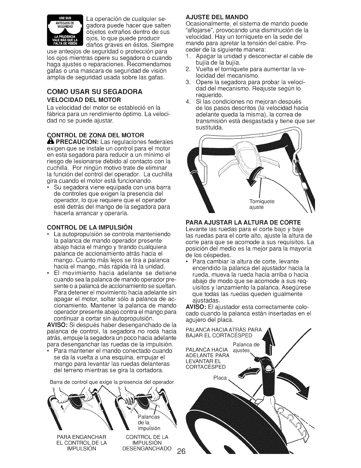
Laoperaci6ndecualquierse-
gadorapuedehacerquesalten
objetosextraflosdentrodesus
ojos,Ioquepuedeproducir
daflosgravesenestos.Siempre
useanteojosdeseguridado protecci6npara
losojosmientrasoperesusegadorao cuando
hagaajusteso reparaciones.Recomendamos
gafasounamascaradeseguridaddevisi6n
ampliadeseguridadusadasobrelasgafas.
SEGURIDAD
COiVIO USAR SU SEGADORA
VELOCIDAD DEL MOTOR
La velocidad del motor se estableci6 en la
fb.brica para un rendimiento 6ptimo. La veloci-
dad no se puede ajustar.
NTROL DE ZONA DEL MOTOR
PRECAUCION: Las regulaciones federales
exigen que se instale un control para el motor
en esta segadora para reducir a un minimo el
riesgo de lesionarse debido al contacto con la
cuchilla. Pot ningOn motivo trate de eliminar
la funci6n del control del operador. La cuchilla
gira cuando el motor estb. funcionando.
• Su segadora viene equipada con una barra
de controles que exigen la presencia del
operador, Io que requiere que el operador
este detrb.s del mango de la segadora para
hacerla arrancar y operarla.
CONTROL DE LA IMPULSION
• La autopropulsi6n se controla manteniendo
la palanca de mando operador presente
abajo hacia el mango y tirando cualquiera
palanca de accionamiento atr_.s hacia el
mango. Cuanto mb.s lejos se tira a palanca
hacia el mango, mb.s rb.pida fib. la unidad.
• El movimiento hacia adelante se detiene
cuando sea la palanca de mando operador pre-
sente o a palanca de accionamiento se sueltan.
Para detener el movimiento hacia adelante sin
apagar el motor, soltar s61o a palanca de ac-
cionamiento. Mantener la palanca de mando
operador presente abajo contra el mango para
continuar a cortar sin autopropulsi6n.
AVlSO: Si despues haber desenganchado de la
palanca de control, la segadora no roda hacia
atrb.s, empuje la segadora un poco hacia adelante
para desenganchar las ruedas de la impulsi6n.
• Para mantener el mando conectado cuando
se da la vuelta a una esquina, empujar el
mango para levantar las ruedas delanteras
del terreno mientras se gira la cortadora.
Barra de control que e <ige la presencia del operador
PARA ENGANCHAR
EL CONTROL DE LA
IMPULSION
Palan(
de la
imputsi6n
CONTROL DE LA
IMPULSION
DESENGANCHADO
AJUSTE DEL MANDO
Ocasionalmente, el sistema de mando puede
"aflojarse', provocando una disminuci6n de la
velocidad. Hay un torniquete en la sede del
mando para apretar la tensi6n del cable. Pro-
ceder de la siguiente manera:
1. Apagar la unidad y desconectar el cable de
bujia de la bujia.
2. Vuelta el torniquete para aumentar la ve-
Iocidad del mecanismo.
3. Opere la segadora para probar la veloci-
dad del mecanismo. Reajuste seg0n Io
requerido.
4. Si las condiciones no mejoran despues
de los pasos descritos (la velocidad hacia
adelante queda la misma), la correa de
transmisi6n est,. desgastada y tiene que set
sustituida.
Torniquete
ajuste
PARA AJUSTAR LA ALTURA DE CORTE
Levante las ruedas para el corte bajo y baje
las ruedas para el corte alto, ajuste la altura de
corte para que se acomode a sus requisitos. La
posici6n del medio es la mejor para la mayor[a
de los cespedes.
• Para cambiar la altura de corte, levante
encendido la palanca del ajustador hacia la
rueda, mueva la rueda hacia arriba o hacia
abajo de modo que se acomode a sus req-
uisitos y lanzamiento la palanca. Aseg0rese
que todas las ruedas queden igualmente
ajustadas.
AViSO: El ajustador esta correctamente colo-
cado cuando la palanca estan insertadas en el
agujero del placa.
PALANCA HACIA ATRAS PARA
BAJAR EL CORTACI_SPED
PALANCA HACIA
ADELANTE PARA
LEVANTAR EL
CORTAC[_SPED
Palanca de
ajustes
Placa
26
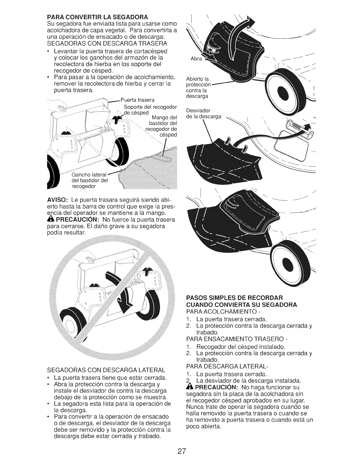
PARA CONVERTIR LA SEGADORA
Su segadora fue enviada lista para usarse como
acolchadora de capa vegetal. Para convertida a
una operaci6n de ensacado o de descarga:
SEGADORAS CON DESCARGA TRASERA
• Levantar la puerta trasera de cortacesped
y colocar los ganchos del armaz6n de la
recolectora de hierba en los soporte del
recogedor de cesped.
• Para pasar a la operaci6n de acolchamiento,
remover la recolectora de hierba y cerrar la
puerta trasera.
trasera
Soporte det recogedor
Je c6sped Mango del
bastidor del
"_recogedor de
' c6sped
"\.
Gancho
delbastidordel
recogedor
AVISO: Le puerta trasara seguirb, siendo abi-
erto hasta la barra de control que exige la pres-
encia del operador se mantiene a la mango.
,_ PREOAUCION: No fuerce la puerta trasera
para cerrarse. El da_o grave a su segadora
podia resultar.
I \ \
Abierto ta
proteccid
contra ta
descarga
Desviador
de la descarga
\
I
I
SEGADORAS CON DESCARGA LATERAL
• La puerta trasera tiene que estar cerrada.
• Abra la protecci6n contra la descarga y
instale el desviador de contra la descarga
debajo de la protecci6n como se muestra.
• La segadora esta lista para la operaci6n de
la descarga.
• Para convertir a la operaci6n de ensacado
o de descarga, el desviador de la descarga
debe set removido y la protecci6n contra la
descarga debe estar cerrada y trabado.
PASOS SIMPLES DE RECORDAR
CUANDO CONVIERTA SU SEGADORA
PARA ACOLCHAMIENTO -
1. La puerta trasera cerrada.
2. La protecci6n contra la descarga cerrada y
trabado.
PARA ENSACAMIENTO TRASERO -
1. Recogedor del cesped instalado.
2. La protecci6n contra la descarga cerrada y
trabado.
PARA DESCARGA LATERAL-
1. La puerta trasera cerrada.
2. La desviador de la descarga instalada.
PREOAUOION: No haga funcionar su
segadora sin la placa de la acolchadora sin
el recogedor cesped aprobados en su lugar.
Nunca trate de operar la segadora cuando se
halla removido la puerta trasera o cuando se
ha removido a puerta trasera o cuando esta un
poco abierta.
27
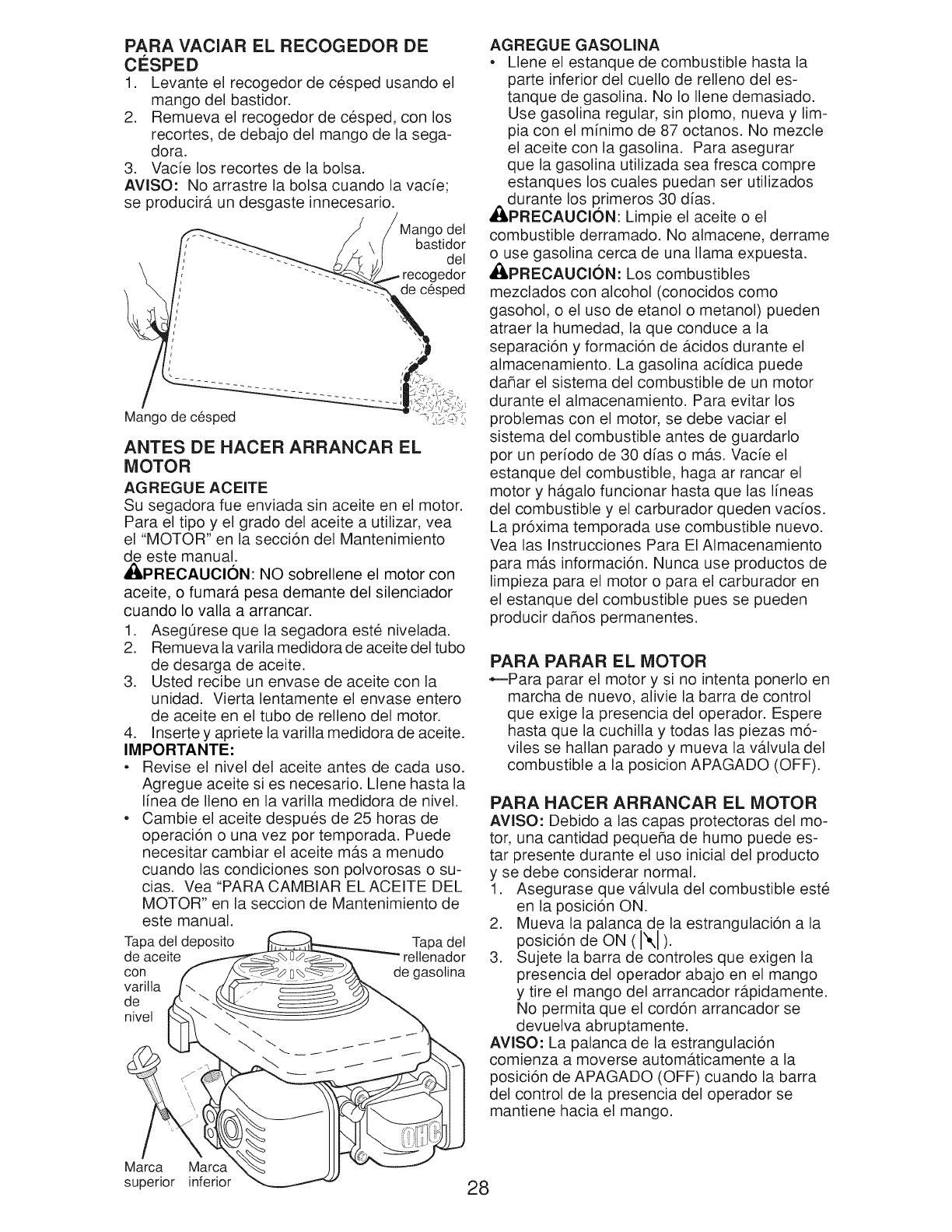
PARA VAClAR EL RECOGEDOR DE
CESPED
1. Levante el recogedor de cesped usando el
mango del bastidor.
2. Remueva el recogedor de cesped, con los
recortes, de debajo del mango de la sega-
dora.
3. Vacie los recortes de la bolsa.
AVlSO: No arrastre la bolsa cuando la vacie;
se producir_, un desgaste innecesario.
Mango del
bastidor
del
........ edor
.... de c6sped
Mango de c6sped
ANTES DE HACER ARRANCAR EL
MOTOR
AGREGUE ACEITE
Su segadora fue enviada sin aceite en el motor.
Para el tipo y el grado del aceite a utilizar, vea
el "MOTOR" en la secci6n del Mantenimiento
de este manual.
,_PRECAUCl0N: NO sobrellene el motor con
aceite, o fumar_, pesa demante del silenciador
cuando Io valla a arrancar.
1. AsegOrese que la segadora este nivelada.
2. Remueva la varila medidora de aceite del tubo
de desarga de aceite.
3. Usted recibe un envase de aceite con la
unidad. Vierta lentamente el envase entero
de aceite en el tubo de relleno del motor.
4. Inserte y apriete la varilla medidora de aceite.
IMPORTANTE:
• Revise el nivel del aceite antes de cada uso.
Agregue aceite si es necesario. Llene hasta la
I[nea de Ileno en la varilla medidora de nivel.
• Cambie el aceite despues de 25 horas de
operaci6n o una vez pot temporada. Puede
necesitar cambiar el aceite mb.s a menudo
cuando las condiciones son polvorosas o su-
cias. Vea "PARA CAMBIAR EL ACEITE DEL
MOTOR" en la seccion de Mantenimiento de
este manual.
Tapa del deposito _ Tapa del
de aceite _%E]o_ --""- rellenador
con,, f_o 0%_ de gasotina
AGREGUE GASOLINA
• Llene el estanque de combustible hasta la
parte inferior del cuello de relleno del es-
tanque de gasolina. No Io Ilene demasiado.
Use gasolina regular, sin plomo, nueva y lim-
pia con el minimo de 87 octanos. No mezcle
el aceite con la gasolina. Para asegurar
que la gasolina utilizada sea fresca compre
estanques los cuales puedan ser utilizados
durante los p.rimeros 30 dias.
,APRECAUClON: Limpie el aceite o el
combustible derramado. No almacene, derrame
o use gasolina cerca de una llama expuesta.
,APRECAUClON: Los combustibles
mezclados con alcohol (conocidos como
gasohol, o el uso de etanol o metanol) pueden
atraer la humedad, la que conduce a la
separaci6n y formaci6n de b.cidos durante el
almacenamiento. La gasolina acfdica puede
dahar el sistema del combustible de un motor
durante el almacenamiento. Para evitar los
problemas con el motor, se debe vaciar el
sistema del combustible antes de guardarlo
por un per[odo de 30 dias o mb.s. Vacie el
estanque del combustible, haga ar rancar el
motor y hb.galo funcionar hasta que las I[neas
del combustible y el carburador queden vacios.
La pr6xima temporada use combustible nuevo.
Vea las Instrucciones Para El Almacenamiento
para m_.s informaci6n. Nunca use productos de
limpieza para el motor o para el carburador en
el estanque del combustible pues se pueden
producir dahos permanentes.
PARA PARAR EL MOTOR
,_--Para parar el motor y si no intenta ponerlo en
marcha de nuevo, alivie la barra de control
que exige la presencia del operador. Espere
hasta que la cuchilla y todas las piezas m6-
viles se hallan parado y mueva la vb.lvula del
combustible a la posicion APAGADO (OFF).
PARA HACER ARRANCAR EL MOTOR
AVlSO: Debido a las capas protectoras del mo-
tor, una cantidad pequeSa de humo puede es-
tar presente durante el uso inicial del producto
y se debe considerar normal.
1. Asegurase que v_tlvula del combustible este
en la posici6n ON.
2. Mueva la palanca de la estrangulaci6n a la
posici6n de ON (I",1).
3. Sujete la barra de controles que exigen la
presencia del operador abajo en el mango
y tire el mango del arrancador rb.pidamente.
No permita que el cord6n arrancador se
devuelva abruptamente.
AVlSO: La palanca de la estrangulaci6n
comienza a moverse autom_.ticamente a la
posici6n de APAGADO (OFF) cuando la barra
del control de la presencia del operador se
mantiene hacia el mango.
28
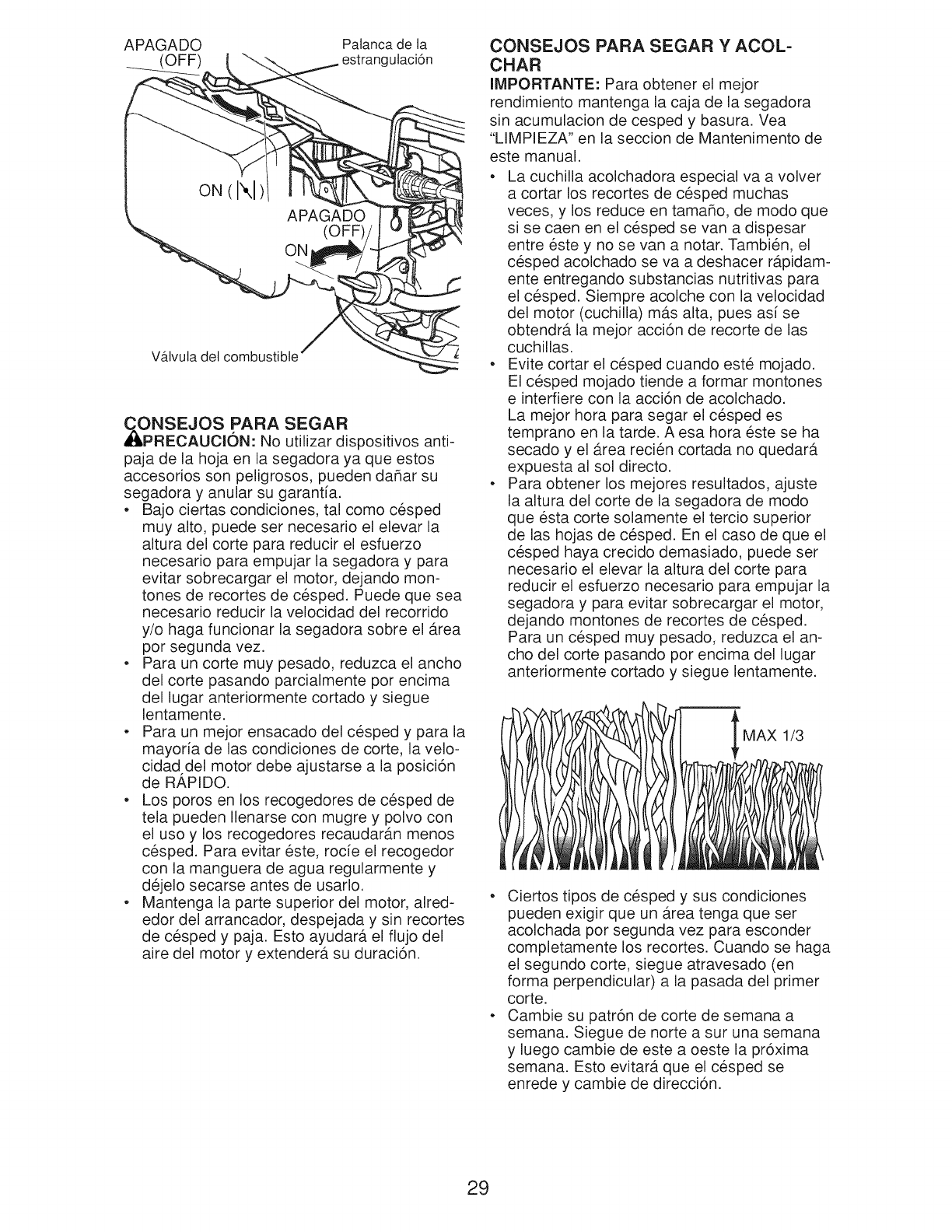
APAGADO Palanca de ta
ulaci6n
V_tvuta det combustible
CONSEJOS PARA SEGAR
AI_PRECAUClON: No utilizar dispositivos anti-
paja de la hoja en la segadora ya que estos
accesorios son peligrosos, pueden daflar su
segadora y anular su garanfia.
• Bajo ciertas condiciones, tal como cesped
muy alto, puede set necesario el elevar la
altura del corte para reducir el esfuerzo
necesario para empujar la segadora y para
evitar sobrecargar el motor, dejando mon-
tones de recortes de cesped. Puede que sea
necesario reducir la velocidad del recorrido
y/o haga funcionar la segadora sobre el _.rea
pot segunda vez.
• Para un corte muy pesado, reduzca el ancho
del corte pasando parcialmente pot encima
del lugar anteriormente cortado y siegue
lentamente.
• Para un mejor ensacado del cesped y para la
mayoria de las condiciones de corte, la velo-
cidad del motor debe ajustarse a la posici6n
de R,&PIDO.
• Los poros en los recogedores de cesped de
tela pueden Ilenarse con mugre y polvo con
el uso y los recogedores recaudarb.n menos
cesped. Para evitar este, rode el recogedor
con la manguera de agua regularmente y
dejelo secarse antes de usarlo.
• Mantenga la parte superior del motor, alred-
edor del arrancador, despejada y sin recortes
de cesped y paja. Esto ayudarb, el fiujo del
aire del motor y extender,, su duraci6n.
CONSEJOS PARA SEGAR Y ACOL-
CHAR
IMPORTANTE: Para obtener el mejor
rendimiento mantenga la caja de la segadora
sin acumulacion de cesped y basura. Vea
"LIMPIEZA" en la seccion de Mantenimento de
este manual.
• La cuchilla acolchadora especial va a volver
a cortar los recortes de cesped muchas
veces, y los reduce en tamaflo, de modo que
si se caen en el cesped se van a dispesar
entre este y no se van a notar. Tambien, el
cesped acolchado se va a deshacer rb.pidam-
ente entregando substancias nutritivas para
el cesped. Siempre acolche con la velocidad
del motor (cuchilla) mb.s alta, pues asi se
obtendr_, la mejor acci6n de recorte de las
cuchillas.
• Evite cortar el cesped cuando este mojado.
El cesped mojado tiende a formar montones
e interfiere con la acci6n de acolchado.
La mejor hora para segar el cesped es
temprano en la tarde. A esa hora este se ha
secado y el Area recien cortada no quedar_.
expuesta al sol directo.
• Para obtener los mejores resultados, ajuste
la altura del corte de la segadora de modo
que esta corte solamente el tercio superior
de las hojas de cesped. En el caso de que el
cesped haya crecido demasiado, puede set
necesario el elevar la altura del corte para
reducir el esfuerzo necesario para empujar la
segadora y para evitar sobrecargar el motor,
dejando montones de recortes de cesped.
Para un cesped muy pesado, reduzca el an-
cho del corte pasando pot encima del lugar
anteriormente cortado y siegue lentamente.
MAX 1/3
• Ciertos tipos de cesped y sus condiciones
pueden exigir que un Area tenga que ser
acolchada pot segunda vez para esconder
completamente los recortes. Cuando se haga
el segundo corte, siegue atravesado (en
forma perpendicular) a la pasada del primer
corte.
• Cambie su patr6n de corte de semana a
semana. Siegue de norte a sur una semana
y luego cambie de este a oeste la pr6xima
semana. Esto evitar_t que el cesped se
enrede y cambie de direcci6n.
29
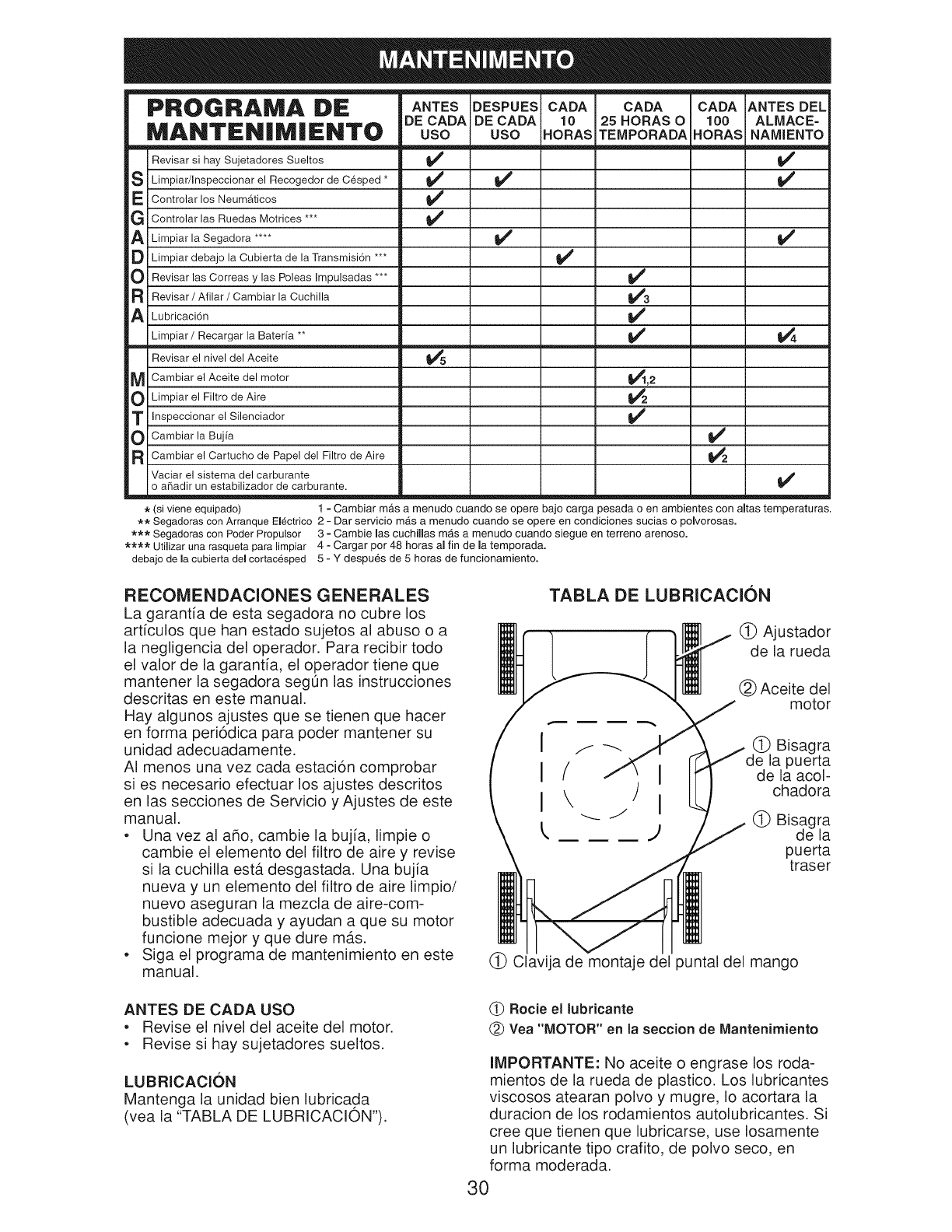
PROGRAMA DE
MANTEN|M|ENTO
Revisar si hay Sujetadores Sueltos _#
S Limpiar/Inspeccionar el Recogedor de Cesped *
E Controlar los Neumaticos
G Controlar las Ruedas Motrices *** _#_
_1_ Limpiar la Segadora ....
[_ Limpiar debajo la Cubierta de la Transmisi6n ***
O Revisar las Correas y las Poleas Impulsadas ***
F{ Revisar /Afilar /Cambiar la Cuchilla
ALubricaci6n
Limpiar/Recargar la Baterfa **
Revisar el nivel del Aceite
M Cambiar el Aceite del motor
O Limpiar el Filtro de Aire
T Inspeccionar el Silenciador
O Cambiar la Bujfa
R Cambiar el Cartucho de Papel del Filtro de Aire
Vaciar el sistema del carburante
o aifiadir un estabilizador de carburante.
ANTES DESPUES
DE CADA DE CADA
USO USO
CADA CADA CADA ANTES DEL
10 25 HORAS O 100 ALMACE=
HORAS TEMPORADA HORAS NAMIENTO
v"
v' v'
v' v'
v'
v'
v'
v'
v'
_,2
v'
v'
*(si viene equipado) 1 - Cambiar mas a menudo cuando se opere bajo carga pesada o en ambientes con altas temperaturas,
** Segadoras con Arranque Electrico 2 - Dar servicio mas a menudo cuando se opere en condiciones sucias o polvorosas.
*** Segadoras con Poder Propulsor 3 - Gamble las cuohillas m_s a menudo cuando siegue en terreno arenoso.
**** Utilizar una rasqueta para limpiar 4 - Cargar por 48 horas al fin de la temporada.
debajo de macubierta del cortacesped 5 - Y despu_s de 5 horas de funcionamiento.
RECOMENDAClONES GENERALES
La garantia de esta segadora no cubre los
arficulos que han estado sujetos al abuso o a
la negligencia del operador. Para recibir todo
el valor de la garantia, el operador tiene que
mantener la segadora seg0n las instrucciones
descritas en este manual.
Hay algunos ajustes que se tienen que hacer
en forma peri6dica para poder mantener su
unidad adecuadamente.
AI menos una vez cada estaci6n comprobar
si es necesario efectuar los ajustes descritos
en las secciones de Servicio y Ajustes de este
manual.
•Una vez al aho, cambie la buj[a, limpie o
cambie el elemento del filtro de aire y revise
si la cuchilla estb. desgastada. Una buj[a
nueva y un elemento del filtro de aire limpio/
nuevo aseguran la mezcla de aire-com-
bustible adecuada y ayudan a que su motor
funcione mejor y que dure mb.s.
• Siga el programa de mantenimiento en este
manual.
TABLA DE LUBRICACION
(_ Ajustador
de la rueda
(_) Aceite del
motor
(_ Bisagra
la puerta
de la acol-
chadora
(_ Bisagra
de la
puerta
traser
(_) Clavija de montaje del puntal del mango
ANTES DE CADA USO
•Revise el nivel del aceite del motor.
• Revise si hay sujetadores sueltos.
LUBRICACl0N
Mantenga la unidad bien lubricada
(vea la "TABLA DE LUBRICACION").
(_ Rocie el Jubricante
(_) Vea "MOTOR" en la seccion de Mantenimiento
IMPORTANTE: No aceite o engrase los roda-
mientos de la rueda de plastico. Los lubricantes
viscosos atearan polvo y mugre, Io acortara la
duracion de los rodamientos autolubricantes. Si
cree que tienen que lubricarse, use Iosamente
un lubricante tipo crafito, de polvo seco, en
forma moderada.
30
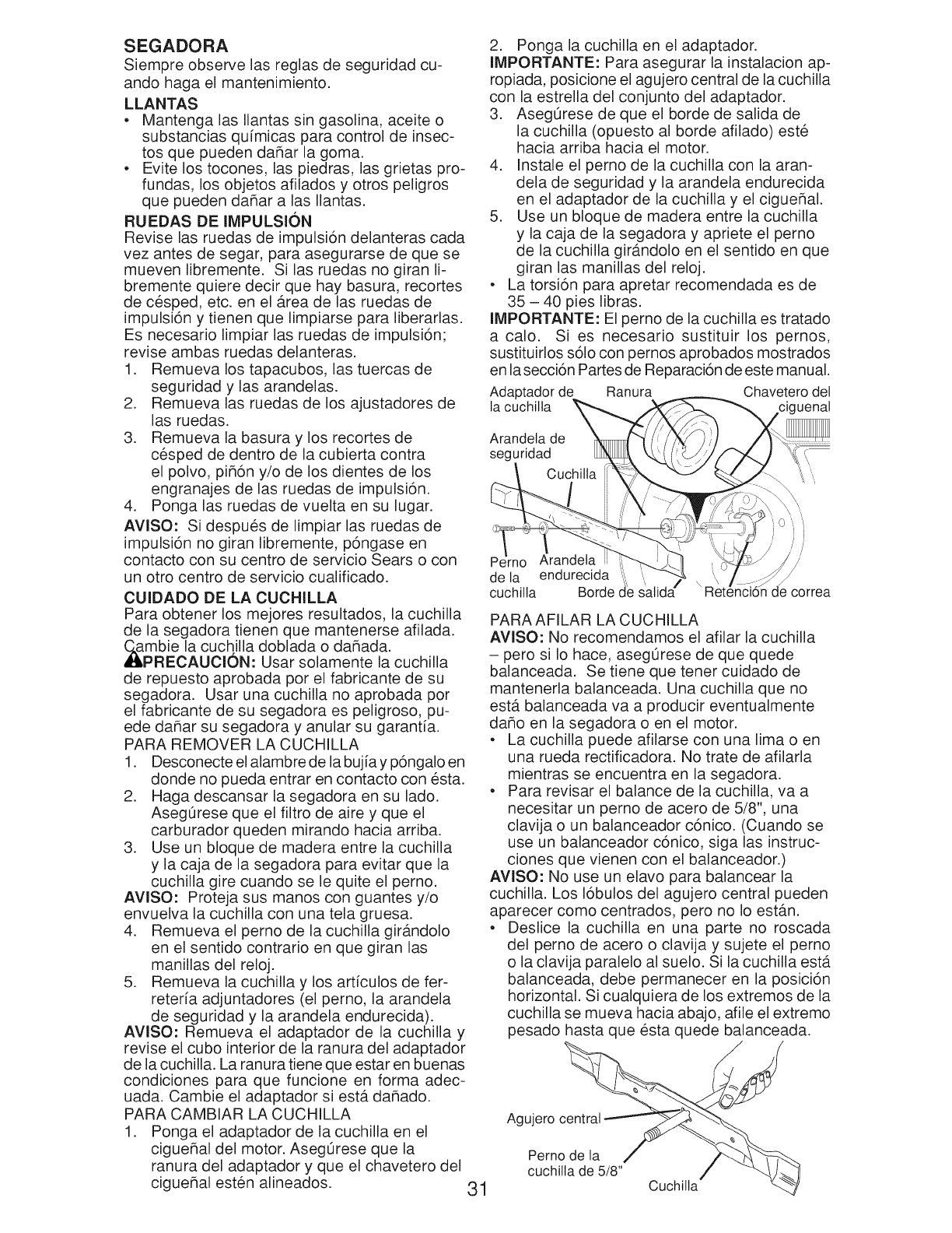
SEGADORA
Siempre observe las reglas de seguridad cu-
ando haga el mantenimiento.
LLANTAS
• Mantenga las Ilantas sin gasolina, aceite o
substancias qu[micas para control de insec-
tos que pueden daflar la goma.
• Evite los tocones, las piedras, las grietas pro-
fundas, los objetos afilados y otros peligros
que pueden daflar alas Ilantas.
RUEDAS DE IMPULSION
Revise las ruedas de impulsi6n delanteras cada
vez antes de segar, para asegurarse de que se
mueven libremente. Si las ruedas no giran li-
bremente quiere decir que hay basura, recortes
de cesped, etc. en el Area de las ruedas de
impulsi6n y tienen que limpiarse para liberarlas.
Es necesario limpiar las ruedas de impulsi6n;
revise ambas ruedas delanteras.
1. Remueva los tapacubos, las tuercas de
seguridad y las arandelas.
2. Remueva las ruedas de los ajustadores de
las ruedas.
3. Remueva la basura y los recortes de
cesped de dentro de la cubierta contra
el polvo, pifl6n y/o de los dientes de los
engranajes de las ruedas de impulsi6n.
4. Ponga las ruedas de vuelta en su lugar.
AVISO: Si despues de limpiar las ruedas de
impulsi6n no giran libremente, p6ngase en
contacto con su centro de servicio Sears o con
un otto centro de servicio cualificado.
CUIDADO DE LA CUCHILLA
Para obtener los mejores resultados, la cuchilla
de la segadora tienen que mantenerse afilada.
,l_pmbie la cuchilla doblada o daflada.
RECAUCiON: Usar solamente la cuchilla
de repuesto aprobada por el fabricante de su
segadora. Usar una cuchilla no aprobada por
el fabricante de su segadora es peligroso, pu-
ede daflar su segadora y anular su garantia.
PARA REMOVER LA CUCHILLA
1. Desconecte el alambre de la bujia y p6ngalo en
donde no pueda entrar en contacto con esta.
2. Haga descansar la segadora en su lado.
Aseg0rese que el filtro de aire y que el
carburador queden mirando hacia arriba.
3. Use un bloque de madera entre la cuchilla
y la caja de la segadora para evitar que la
cuchilla gire cuando se le quite el perno.
AVlSO: Proteja sus manos con guantes y/o
envuelva la cuchilla con una tela gruesa.
4. Remueva el perno de la cuchilla gir_.ndolo
en el sentido contrario en que giran las
manillas del reloj.
5. Remueva la cuchilla y los arficulos de fer-
reteria adjuntadores (el perno, la arandela
de seguridad y la arandela endurecida).
AViSO: Remueva el adaptador de la cuchilla y
revise el cubo interior de la ranura del adaptador
de la cuchilla. La ranura tiene que estar en buenas
condiciones para que funcione en forma adec-
uada. Cambie el adaptador si estb. daflado.
PARA CAMBIAR LA CUCHILLA
1. Ponga el adaptador de lacuchilla en el
cigueflal del motor. Aseg0rese que la
ranura del adaptador y que el chavetero del
cigueflal esten alineados. 31
2. Ponga la cuchilla en el adaptador.
IMPORTANTE: Para asegurar la instalacion ap-
ropiada, posicione el agujero central de la cuchilla
con la estrella del conjunto del adaptador.
3. AsegOrese de que el borde de salida de
la cuchilla (opuesto al borde afilado) este
hacia arriba hacia el motor.
4. Instale el perno de la cuchilla con la aran-
dela de seguridad y la arandela endurecida
en el adaptador de la cuchilla y el cigueflal.
5. Use un bloque de madera entre la cuchilla
y la caja de la segadora y apriete el perno
de la cuchilla gir_tndolo en el sentido en que
giran las manillas del reloj.
• La torsi6n para apretar recomendada es de
35 - 40 pies libras.
IMPORTANTE: El perno de la cuchilla es tratado
a calo. Si es necesario sustituir los pernos,
sustituirlos s61ocon pernos aprobados mostrados
en la secci6n Partes de Reparaci6n de este manual.
Adaptador de Ranura Chavetero del
la cuchilta "uenat
Arandeta de
seguridad
Pc rno Arandeta i
de la endurecida
cuchilla Borde
) i
correa
PARA AFILAR LA CUCHILLA
AVlSO: No recomendamos el afilar la cuchilla
- pero si Io hace, asegOrese de que quede
balanceada. Se tiene que tenet cuidado de
mantenerla balanceada. Una cuchilla que no
est,. balanceada va a producir eventualmente
daflo en la segadora o en el motor.
• La cuchilla puede afilarse con una lima o en
una rueda rectificadora. No trate de afilarla
mientras se encuentra en la segadora.
• Para revisar el balance de la cuchilla, va a
necesitar un perno de acero de 5/8", una
clavija o un balanceador c6nico. (Cuando se
use un balanceador c6nico, siga las instruc-
clones que vienen con el balanceador.)
AVISO: No use un elavo para balancear la
cuchilla. Los 16bulos del agujero central pueden
aparecer como centrados, pero no Io estb.n.
• Deslice la cuchilla en una parte no roscada
del perno de acero o clavija y sujete el perno
o la clavija paralelo al suelo. Si la cuchilla estb.
balanceada, debe permanecer en la posici6n
horizontal. Si cualquiera de los extremos de la
cuchilla se mueva hacia abajo, afile el extremo
pesado hasta que esta quede balanceada.
Agujero central
Perno de la
cuchilla de 5/8" Cuchilla

RECOGEDOR DE ClaSPED
• El recogedor de cesped puede ser rociado
con el agua de la manguera pero tiene que
estar seco cuando se vaya a usar.
• Revise su recogedor de cesped a menudo
para verificar si estA dahado o deteriorado.
Se va a desgastar con el uso normal. Si se
necesita cambiar el recogedor, cambielo
solamente por uno que sea aprobado por el
fabricante. De el n0mero del modelo de la
segadora cuando Io ordene.
CAJA DE ENGRANAJES
• Para mantener el sistema de impulsi6n
funcionando en forma adecuada, la caja
de engranajes y el Area alrededor de la
impulsi6n tienen que mantenerse limpias y
sin acumulaci6n de basura. Limpie debajo
de la cubierta de la impulsi6n dos veces por
temporada.
• La caja de engranajes se Ilena con lubricante
hasta el nivel adecuado en la fabrica. La
0nica vez que el lubricante necesita atenci6n
es cuando se le ha prestado servicio a la
caja de engranajes.
MOTOR
El mantenimiento, la reparaci6n, o el reemplazo
de cualquier dispositivos o sistemas del control
de la emisi6n, los cuales sean hechos al costo
del cliente, pueden ser realizados por cualquier
individuo o establecimiento de reparaci6n de
motor. Los reparos que caen bajo garantia
deben ser realizados por un establecimiento de
servicio de reparaci6n de motor autorizado.
LUBRICACION
Use solamente aceite de detergente de alta
calidad clasificado con la clasificaci6n SG-SL
de servicio API. Seleccione la calidad de visco-
sidad SAE seg0n su temperatura de operaci6n
esperada.
CALIDADES DE VlSCOSIDAD DE SAE
°F -20 0 30 32 40 60 80 100
°c -do -2; -_; ; 1; _0 1o 40
GAMA DE TEMPERATURA ANTICIPADA ANTES DEL PROXIMO CAMBIO DE ACEITE
AViSO: Los aceites de multiviscosidad (5W30,
10W30, etc.) mejoran el arranque en clima fr[o,
y revise el nivel del aceite del motor menudo,
para evitar un posible daho en el motor, debido
a que no tiene suficiente aceite.
Cambie el aceke despues de 25 horas de
operaci6n o por Io menos una vez al aho si la
segadora se utiliza menos 25 horas el aho.
Revise el nivel del aceJte del carter antes de
arrancar el motor y despues de cada cinco (5)
horas de uso continuado. Apdete el tap6n del
aceite en forma segura cada vez que revise el
nivel del aceJte.
PARA CAMBIAR EL ACEITE DEL MOTOR
AVlSO: Antes de inclinar la segadora para dre-
nar el aceite, drene el tanque de combustible
haciendo correr el motor hasta que el tanque
este vacio.
1. Desconecte el alambre de la buj[a y
p6ngalo de modo que no pueda entrar en
contacto con esta.
2. Remueva la tapa del dep6sito del aceite;
dejela a un lado en una superficie limpia.
3. Incline la cortadora de cesped por este
costado tal como se muestra y purgue el
aceite en un recipiente id6neo. Mueva la
segadora de atras para adelante para re-
mover todo el aceite que se haya quedado
atrapado dentro del motor.
Envase
.
5.
.
Limpie todo el aceite derramado en la sega-
dora yen el lado del motor.
Rellene el motor con aceite. Vierta lenta-
mente el aceite en el tubo de relleno del
motor.
Permita que el aceite se asiente. Use un
medidor en la tapa/varilla indicadora del
nivel para relleno del aceite para revisar el
nivel. Inserte la varilla indicadora de nivel
en el tubo, y haga descansar la tapa del
dep6sito para relleno del aceite en el tubo
al leer las medidas. NO enrosque el tap6n
cuando este tomando una lectura.
Tapa del
deposito de
aceite con
varilla de
nivet _
Marca _
superbr_
Marca _-
inferior
7. Contin0e agregando cantidades pequeas
de aceite y vuelva a inspeccionar la varilla
medidora hasta que lea Ileno (FULL). NO
sobrellene el motor con aceite, o fumara
cuando Io valla a arrancar.
8. AsegOrese de apretar la varilla medidora
del aceite antes de arrancar el motor.
9. Vuelva a conectar el alambre de la buj[a a
esta.
FILTRO DE AIRE
Su motor puede sufrir averias y funcionar de
manera incorrecta con un filtro del aire sucio.
Sustituir el papel del cartucho una vez al aho o
tras 100 horas de funcionamiento, mas a menu-
do si se utiliza en condiciones de suciedad y
32polvo particulares. No lave el filtro de aire.

PARALIMPIARELFILTRODEAIRE
1. Remuevalacubierta.
2. Cuidadosamente,remuevaelcartucho.
3. LimpielogolpeAndolosuavementeenuna
superficieplana.Siesta muysuciocambie
elcartucho.
_PREOAUOION:Lossolventesdepetr61eo,
talescomoelkeroseno,nosedebenusarpara
limpiarelcartucho.Puedenproducireldeteri-
orodeeste.Noaceiteelcartucho.Nouseaire
a presi6nparalimpiarloo secarlo.
4. Instaleelcartucho,luegovuelvaa ponerla
cubierta.
Oreja
Cubierta det fittro de aire
SILENClADOR
Inspeccione y cambie el silenciador siesta corroi-
do puede producir un peligro de incendio y/o daho.
BUJJA
Cambie el bujia al comienzo de cada tempo-
rada de siega o despues de cada 100 horas
de operaci6n, Io que suceda primero. El tipo
de bujia y el ajuste de la abertura aparecen en
"ESPECIFICAClONES DEL PRODUCTO" en la
secci6n de Mantenimiento de este manual.
LIMPIEZA
iMPORTANTE: Para obtener el mejor rendimineto,
mantenga la caja de la segadora sin acumulacion
de cesped y basura. Limpie la parte de abajo de
su segadora despues de cada uso.
_PRECAUCION: Desconecte el alambre de
la bujia y p6ngalo en donde no pueda entrar en
contacto con esta.
• Haga descansar la segadora en su lado.
AsegOrese que el filtro de aire y que el carbu-
rador queden mirando hacia arriba. Limpie la
parte inferior de su segadora raspAndola para
remover la acumulaci6n de cesped y basura.
• Limpie el motor a menudo para evitar que
se acumule la basura. Un motor tapado fun-
ciona mAs caliente y se acorta su duraci6n.
• Mantenga las superficies pulidas y las rue-
das sin gasolina, aceite, etc.
• No recomendamos el uso de una manguera
de jardin para limpiar la segadora a menos
que el sistema electrico, el silenciador, el
filtro de aire y el carburador esten tapados
para evitar que les entre el agua. El agua en
el motor puede acortar la duraci6n de este.
DERRUBIO DEL AGUA
Su cortacespedes de cesped se equipa de una
guarnici6n que permita la limpieza rApida y fAcil
del superficie inferior de la cubierta. Para utilizar
esta caracteristica, siga de la forma siguiente:
1. Mueva el cortacespedes de cesped a un Area
de la hierba cortada o de otra superficie dura.
NOTA: El agua, la hierba y la otra ruina escur-
riran debajo de la cubierta del cortacespedes
durante el proceso del derrubio.
2. Quite el colector de la hierba y descargue
el montaje del canal inclinado del cortaces-
pedes de cesped.
3. Cierrelapuertadel mulcher(si estaequipado).
4. Conecte una manguera del jardin con la
guarnici6n donde demostrado.
IMPORTANTE: Sea seguro que la manguera
del jardin no esta encaminada debajo de la
cubierta del cortacespedes de cesped ni que
esta enredada en las ruedas.
5. Gire el abastecimiento y la comprobaci6n
para de agua escapes en la guarnici6n.
Si no hay escapes presentes, encienda el
motor (seg0n Io descrito en la secci6n de la
operaci6n de este manual) y deje el motor
funcionar hasta que el superficie inferior del
cortacespedes de cesped esta limpio.
_;:_ADVERTENClA: No contrate el sistema de
impulsi6n durante el proceso del derrubio.
6. Apague el motor.
7. Apague el abastecimiento de agua y quite
la manguera de la guarnici6n.
PRECAUCION: No quite la manguera de la
guarnici6n mientras que el motor esta funciona-
ndo. El agua en motor puede dar lugar a vida
acortada del motor.
8. Encienda el motor (seg0n Io descrito en la
secci6n de la operaci6n de este manual)
y deje el motor funcionar pot un minuto
completo para quitar exceso de agua del
cortacespedes.
Guarnici6n
33
LIMPIE DEBAJO DE LA CUBIERTA DE LA
IMPULSION
Limpie debajo de la cubierta de la impulsi6n
por Io menos dos veces cada temporada.
Raspe debajo de la cubierta con un cuchillo
para masilla o con una herramienta parecida,
para remover toda acumulaci6n de cesped o
basura en la parte inferior de la cubierta de la
impulsi6n.

_,DVERTENClA: Paraevitarlesi6nesserias,antesde darcalquierservicoo de hacerajustes:
1. Sueltelabarradecontroly pareelmotor.
2. AsegOresequelacuchillay quetodaslaspartesmoviblessehayandetenidocompletamente.
3. Desconecteel alambrede labujiay p6ngaloendondenopuedaentrarencontactoconesta.
SEGADORA
PARA AJUSTAR LA ALTURA DE CORTE
Vea "PARA AJUSTAR LA ALTURA DE CORTE"
en la secci6n de Operaci6n de este manual.
DESVlADOR TRASERO
Se proporciona un desviador trasero, adjunto
entre las ruedas traseras de su segadora, para
reducir a un minimo la posibilidad que objetos
sean lanzados hacia afuera de la parte trasera
de la segadora, en la posici6n en donde se
encuentra el operador. Si se daha el desviador
debe cambiarse.
6. Reinstale la fijador de la correa y cubierta
de la impulsi6n.
NOTA: Siempre use la correa aprobada pot la
f_.brica para asegurarse que calce y dure.
Adaptador de Ranura Chavetero del
la cuchilta "uenat
Arandela de
seguridad
PARA REMOVER CORREA DE IMPULSION
1. Remueva la cubierta de la impulsi6n y
fijador de la correa.
2. Remueva la correa en la polea de la caja de
engranajes.
3. Haga descansar la segadora en su lado
con el filtro de aire y el carburador mirando
hacia arriba.
4. Remueva la cuchilla y la adaptador de la
cuchilla.
5. Remueva la correa del polea del motor.
Cubierta
de ta
impulsion
\
Potea de
la caja de
engranajes
Perno Arandeta /
dela endurecida ':, ....
cuchilta Borde de satid_ correa
PARA AJUSTAR EL MANGO
El mango de su segadora cuenta con tres (3)
posiciones de altura - aj0stelo a la altura que le
acomode.
1. Remueva la manilla y el perno portador en
un lado del mango inferior.
2. AI mismo tiempo que sujeta el conjunto del
mango, remueva la manilla y el perno porta-
dor del lado opuesto, alinee el agujero en el
mango con el agujero deseado en el puntal
del mango y vuelva a montar el perno y la
manilla y apri@elos en forma segura.
3. Alinee el lado opuesto del mango con el
agujero de la misma posici6n y aseg0relos
con el perno y la manilla.
Soporte
de mango
Fijador de
la correa
/Correa
PARA CAMBIAR CORREA DE IMPULSION
1. Instale la nueva correa de mando en la
polea del motor y el estribo de la retenci6n
de correa.
2. Colocar la otra extremidad de la nueva
correa de mando a traves del orificio en el
bastidor.
3. Reinstale la adaptador de la cuchilla y
cuchilla.
4. Vuelva la segadora a la posici6n vertical.
5. Instale la correa nueva en la polea de la
caja de engranajes. 34
Perno

MOTOR
El mantenimiento, la reparaci6n, o el reemplazo
de cualquier dispositivos o sistemas del control
de la emisi6n, los cuales sean hechos al costo
del cliente, pueden set realizados pot cualquier
individuo o establecimiento de reparaci6n de
motor. Los reparos que caen bajo garantia
deben set realizados pot un establecimiento de
servicio de reparaci6n de motor autorizado.
VELOCIDAD DEL MOTOR
La velocidad del motor ha sido ajustada en
la f_.brica. No trate de aumentar la velocidad
del motor pues se pueden producir lesiones
personales. Si cree que el motor est,. funcio-
nando demasiado r_.pido o demasiado lento,
Ileve su segadora a mas con su centro de
servicio Sears o con un otto centro de servicio
cualificado.
CARBURADOR
Su carburador tiene un chorro principal fijo no
ajustable para controlar la mezcla. Si su motor
no estb. funcionando en forma adecuada debido
a problemas que se sospecha vienen del carbu-
rador, Ileve su segadora a contacto con su centro
de servicio Sears o con un otto centro de servicio
cualificado para repararla y/o ajustarla.
IMPORTANTE: Nunca manipule el regulador
del motor, el que ha sido ajustado en la f_.brica
para la velocidad del motor adecuada. Puede
set peligroso hacer funcionar el motor a una
velocidad pot sobre el ajuste de alta velocidad
de la f_.brica. Si cree que la velocidad alta
regulada del motor necesita ajuste,contacto con
su centro de servicio Sears o con un otto centro
de servicio cualificado, el que cuenta con el
equipo adecuado y la experiencia para hacer
los ajustes necesarios.
Inmediatamente prepare su segadora para el almacenamiento al final de cada temporada o si la
unidad no se va a usar pot 30 dias o m_.s.
SEGADORA
Cuando se va a guardar la segadora por cierto
periodo de tiempo, limpiela cuidadosamente,
remueva toda la mugre, la grasa, las hojas, etc.
Gu_.rdela en un Area limpia y seca.
1. Limpie toda la segadora (Vea "LIMPIEZA"
en la secci6n de Mantenimento de este
manual).
2. Lubr[quela segOn se muestra en la secci6n
de Mantenimento de este manual.
3. AsegOrese de que todas las tuercas y
clavijas y todos los pernos y tornillos esten
apretados en foma segura. Inspeccione
las partes que se mueven para verificar si
estb.n dafladas, quebradas o desgastadas.
C_.mbielas si es necesario.
4. Retoque todas las superficies que esten
oxidadas o con la pintura picada; use una
lija antes de pintar.
Barra de control
que exige
presencia det
operador
DOBLAR
HACIA
ADELANTE
PARA
ALMACENAR
/////
POSICION
PARA
SEGAR
Mango
superior
Manitla del
mango
Mango inferior
MANGO
Puede doblar el mango de su segadora para el
almacenamiento.
1. Suelte las dos (2) manillas del mango en
cada lado del mango superior y permita que
el mango se doble hacia detras.
2. Remueva las dos (2) manillas y los pernos
de cada lado del mango inferior y pivote el
conjunto entero del mango hacia delante y
permita le que se descanse sobre la sega-
dora.
3. Vuelva a poner las manillas y los pernos al
mango inferior o a los puntales del mango
para la seguridad.
• Cuando prepare su mango a partir de la
posici6n de almacenamiento, el mango infe-
rior nesecitara cerrarlo manualmente para la
posici6n de sega.
IMPORTANTE: Cuando doble el mango para el
almacenamiento o el transporte, asegOrese que
Io doble segOn se muestra o purde daflar los
cables de control. 35
Manilla
Sopo_e
de mango
Perno

MOTOR
SISTEMA DE COMBUSTIBLE
iMPORTANTE: Es importante evitar que
se formen depositos de coma en partes
fundamentales del sistemade combustible tales
como el carburador, el filtro del combustible,
la mangura del combustible o en el estanque
durante el almacenamiento. Los combustibles
mezclados con alcohol (conocido come
gasohol o que tienen etanol o metanol)
Pueden atraer humedad, Io que conduce a la
separacion y a la formaci6n de acidos durante
el almacenamiento. La gasolina acida puede
danar el sistema de combustible de un motor
durante el perido de almacenamiento.
• Vaciar el dep6sito del carburante poniendo
en marcha el motor y dej_tndolo funcionar
hasta que el carburante termine y el
carburador este vacio.
• Nunca use los productos para limpieza del
carburador o del motor en el estanque de
combustible pues se pueden producir daflos
permanentes.
• Use combustible nuevo la pr6xima tempo-
rada.
AViSO: El estabilizador de combustible es una
alternativa aceptable para reducir a un minimo
la formaci6n de dep6sitos de goma en el com-
bustible durante el periodo de almacenamiento.
Agregue estabilizador a la gasolina en el es-
tanque de combustible o en el envase para el
almacenamiento. Siempre siga la proporci6n de
mezcla que se encuentra en el envase del estabi-
lizador. Haga funcionar el motor por Io menos 10
minutos despues de agregar el estabilizador, para
permitir que este Ilegue al carburador. No drene la
gasolina del estanque de gasolina y el carburador
si se esta usando estabilizador de combustible.
ACEiTE DEL MOTOR
Drene el aceite (con el motor caliente) y c_.mbielo
con aceite de motor limpio. (Vea "MOTOR" en la
secci6n de Mantenimento de este manual.)
ClLINDRO
1. Remuevalabujia.
2. Vacie una onza (29 ml) de aceite a traves
del agujero de la bujia en el cilindro.
3. Tire la manilla de arranque lentamente unas
cuantas veces para distribuir el aceite.
4. Vuelva a montar la nueva bujia.
OTROS
• No guarde la gasolina de unatemporada a la
otra.
• Cambie el envase de la gasolina si se emp-
ieza a oxidar. La oxidaci6n y/o la mugre en
su gasolina producir_.n problemas.
• Si es posible, guarde su unidad en un recinto
cerrado y ct3brala para protegerla contra el
polvo y la mugre.
• Cubra su unidad con un forro protector
adecuado que no retenga la humedad. No
use plb.stico. El plb.stico no puede respirar, Io
que permite la formaci6n de condensaci6n,
Io que producirb, la oxidaci6n de su unidad.
IMPORTANTE: Nunca cubra la segadora
mientras el motor y las areas de escape todavia
estan calientes.
_PREOAUOION: Nunca almacene la
segadora con gasolina en el estanque dentro
de un edificio en donde los gases pueden
alcanzar una llama expuesta o una chispa.
Permita que se enfHe el motor antes de
almacenarla en algOn recinto cerrado.
SOLUCION DE PROBLEMAS - Yea ia seccion apropiada en el manual amenos que
este dirigido a un centro de servico Sears.
CAUSAPROBLEMA
No arranca 1. Filtro de aire sucio.
2. Sin combustible.
3. Combustible rancio.
4. Agua en el combustible.
5. Alambre de la bujia desconectado.
6. Bujia mala.
7. Cuchilla suelta o adaptador
de la cuchilla quebrado.
8. Barra de control en la
posici6n suelta.
9. Barra de control defectuosa.
10. Vb,lvula del combustible (si equ-
ipada) estb. en la posici6n OFF.
11. Bateria debi (si equipada).
12. Desconecte el conector
de la bateria (si equipada).
13. Fusible quemado.
CORRECClON
1. Limpie/cambie el filtro de aire.
2. Llene el estanque de combustible.
3. Vaciar el estanque y vuelva a Ilenar-
Io con combustible limpio y nuevo.
4. Vaciar el estanque y vuelva a Ilenar-
Io con combustible limpio y nuevo.
5. Conecte el alambre a la bujia.
6. Cambie la bujia.
7. Apriete el perno de la cuchilla
cambie el adaptador de la cuchilla.
8. Presione la barra de control
hacia el mango.
9. Cambie la barra de control.
10. Gire a la vb.lvula del combustible
a la posici6n ON.
11. Cague la bateria.
12. Conecte la bateria al motor.
13. Cambie el fusible.
36

SOLUCION DE PROBLEMAS - Vea ia seccion apropiada en el manuaJ amenos que
este dirigido a un centro de servico Sears.
CAUSAPROBLEMA
Falta de
fuerza
Mal corte-
disparejo
Vibracion
e×cesiva
Cordon
arrancador
dificil de tirar
Recogedor de
cesped no se
llena (si viene
equipado)
1. Cuchilla desgastada, doblada
o suelta.
2. AItura de las ruedas dispareja.
3. Velocidad del motor lenta.
4. Acumulaci6n de cesped, hojas o
basura debajo de la segadora.
5. Demasiado aceite en motor.
6. Velocidad de recorrido
demasiado r_.pida.
.
2.
3.
Cuchilla desgastada, doblada
o suelta.
AItura de las ruedas dispareja.
Dificil de
empujar
Perdida de
impulsion
o retardase
de la
velocidad
Acumulaci6n de cesped, hojas o
basura debajo de la segadora.
1. Cuchilla desgastada, doblada
o suelta.
2. Ciguehal del motor doblado.
1. El freno del volante del motor
estb. aplicado cuando se
suelta la barra de control.
2. Ciguehal del motor doblado.
3. Adaptador de la cuchilla quebrado.
4. Lacuchilla se arrastra en
el cesped.
.
2.
3.
1.
2.
.
4.
AItura de corte demasiado baja.
Levantamiento de la cuchilla
desgastado.
Recogedor sin ventilaci6n de aire.
El cesped estb. demasiado alto o la
altura de la rueda demasiado baja.
Parte trasera de la
caja/cuchilla de la segadora
arrastrb.ndose en el cesped.
Recogedor de cesped
demasiado Ileno.
Posici6n de la altura del mango
no adecuada para usted.
1. Desgaste de lacorrea.
2. La correa estb. fuera de la polea.
3. Cable de la impulsi6n usado o roto.
4. El sistema de control del
mecanismo impulsor "suelto".
CORRECClON
1. Eleve la altura de corte.
2. Eleve la altura de corte.
3. Limpie/cambie el filtro de aire.
4. Limpie la parte inferior de la
caja de la segadora.
5. Revise el nivel del aceite.
6. Corte a una velocidad de
recorrido m_.s lenta.
1. Cambie la cuchilla. Apriete el perno
de la cuchilla.
2. Ajuste todas las ruedas a la misma
altura.
3. Limpie la parte inferior de la
caja de la segadora.
1. Cambie la cuchilla. Apriete el
perno de la cuchilla.
2. P6ngase en contacto con su centro
de servicio Sears o con un otto
centro de servicio cualificado.
1. Presione la barra de control
hacia el mango superior antes
de tirar el cord6n arrancador.
2. P6ngase en contacto con su centro
de servicio Sears o con un otto
centro de servicio cualificado.
3. Cambie el adaptador de la cuchilla.
4. Mueva la segadora a un lugar
en donde el cesped ha sido
cortado o a una superficie firme
para hacer arrancar el motor.
1. Eleve la altura de corte.
2. Cambie las cuchillas.
3. Limpie el recogedor de cesped.
1. Eleve la altura de corte.
2. Eleve la parte trasera de la caja de
la segadora (1) un lugar m_.s alto.
3. Vacie el recogedor de cesped.
4. Ajuste la altura del mango de
modo que le acomode.
1. Revise/cambie correa de impulsi6n.
2. Revise/vuelva a instalar la
3. Cambie el cable de la impulsi6n.
4. Ajuste el control del mecanismo
impulsor.
37

CRAFTSMAN ROTARY LAWN MOWER - - MODEL NUMBER 917,376544
co
co
19
59
85
25 .........."_
54 6,5
24
12
9
84
!7
11
/
\52\
21
55
43
....32
41
28
41
22
63
31
68
3O
27
5O
25
47

CRAFTSMAN ROTARY LAWN MOWER - -MODEL NUMBER 917.376544
KEY
NO.
1
2
3
4
5
6
7
8
9
11
12
Co
_17
18
19
20
21
22
24
25
26
27
28
30
31
32
PART KEY PART KEY PART
NO. DESCRiPTiON NO. NO. DESCRiPTiON NO. NO.
183471X479 Upper Handle 33 420019 Mulcher Door 56 17411312
438391 Cable, Engine Zone Control /34 419946X615 Bracket, Grassbag
Rear Door Prop 35 431131 Kit, Wheel Adjuster, Rear, RH 57 155377
429930X004 Bracket, Upstop (Includes Knob & Pushnut) 58 421241X479
145006 Guide, Cable 36 175735 Hinge Bracket Assembly 59 191574
66426 Wire Tie 38 419942X428 Discharge Deflector 62 431913X004
182398 Handle Knob, Star 39 442470X479 Handle Bracket, LH 63 178848
750634 Screw #10-24 x 1/2 40 438526X479 Handle Bracket, RH 64 - - -
426432X428 Control Bar 41 150406 Bolt, Engine
430653 Rear Door Assembly 42 193000 Spring, Torsion
425575 Hairpin, Door/Handle Pivot 43 191730 Nut, Hex, Nylock 65 197480
189713X428 Handle Knob, Standard 44 431558 Kit, Lawn Mower Housing 68 431134
427120X428 Rear Baffle 45 175650 Rod, Hinge
132004 Keps Locknut 1/4-20 46 421782 Blade Adapter /Pulley 83 750097
194788 Rope Guide 47 421825 Blade, 22" 84 428124
429157 Rear Skirt 48 851074 Washer, Hardened 85 429801X004
419949 Spring, Rear Door, LH, Black 49 850263 Washer, Helical
141841 Screw, Panhead, Torx #20 50 851084 Screw, Machine, Hex Head 96
419948 Spring, Rear Door, RH, Grey 3/8-24 x 1-3/8 Grade 8 - -
409149 Nut, Hex, Flanged 51 430599 Front Baffle
419945 Screw, Rear Door/Handle Pivot 52 404763 Decal, Danger
431880X460 Wheel & Tire Assembly, Rear 53 17000510 Screw, Semi-Gimlett Point
72250505 Bolt, Carriage 5/16-18 x 5/8 1/4-20 x 1/2
413808 Nut, Push 54 88348 Washer, Flat
419407X615 Selector Knob 55 191730 Nut, Hex
419944X007 Latch, Mulcher Door
DESCRiPTiON
Screw, Hex Washer Head
#13 x 3/4
Nut, Hex
Lower Handle
Handle Bolt
Belt Retainer
Screw #10-16 x 5/8
Engine, Honda, Model
Number GCV160-LAS3A
(See Breakdown)
O-Ring
Kit, Wheel Adjust, Rear, LH
(Includes Knob & Pushnut)
Screw
Fastener, Push
Mounting Bracket,
Rear Skirt
197991 Clip, Cable
438096 Owner's Manual,
English/Spanish
Available accessories not included with mower:
-- 71 33623 Gas Can
(2.5 Gallon Container)
- - 71 33500 Fuel Stabilizer
-- 71 33000 SAE 30W Oil
(18 Ounce Bottle)
NOTE: All component dimensions given in U.S. inches. 1 inch = 25.4 mm.
_MPORTANT: Use only Original Equipment Manufacturer (O.E.M.) replacement parts. Failure to do so could be hazardous, damage your lawn mower and void your warranty.

o
/
CRAFTSMAN ROTARY LAWN MOWER - - MODEL NUMBER 917,376544
_" _ 27
54
11
57
28
33 17
/
N
13
12
29
11
16

CRAFTSMAN ROTARY LAWN MOWER - -MODEL NUMBER 917.376544
KEY PART KEY PART
NO. NO. DESCRiPTiON NO. NO. DESCRiPTiON
1 430991 Drive Control Assembly 28 421094
(Includes Cable) 29 409148
9 431649 Cable, Drive 32 194018
10 429544X479 Mounting Bracket, 33 426609
Drive Control 35 431124
11 194231X460 Wheel & Tire Assembly
12 12000058 E- Ring 36 424657
13 403849 Pinion 38 191730
14 189403 Dust Cover 40 406558
15 404845 Pawl, Drive 41 431121
16 67725 Washer, Flat 3/8
17 413808 Nut, Push 54 422507
18 419345X615 Selector Knob 57 419951
20 181698 Screw 80 421114
25 430458X004 Belt Guide Bracket
26 163409 Screw, Hi-Lo Thread 81 419735
#12 x 5/8 82 415585
27 175262 Screw, Pan Head 83 415586
#10-24 x 2-3/4
Drive Cover
Locknut, Hex
Drive Pulley
V-Belt
Kit, Wheel Adjuster, Front, LH
(Includes Knob and Pushnut)
Gearcase Assembly, Complete
Locknut, Hex 1/4-20
Spring
Kit, Wheel Adjuster, Front, RH
(Includes Knob and Pushnut)
Grassbag
Frame, Grassbag
Kit, Water Washout Assembly
(Includes Key Numbers 81 thru 83)
Fitting, Water Washout
Washer, Lock, Internal Tooth
Locknut, Hex, with O-Ring
NOTE: All component dimensions given in U.S. inches. 1 inch = 25.4 mm.
_MPORTANT: Use only Original Equipment Manufacturer (O.E.M.) replacement parts. Failure to do so could be hazardous, damage your lawn mower and void your warranty.
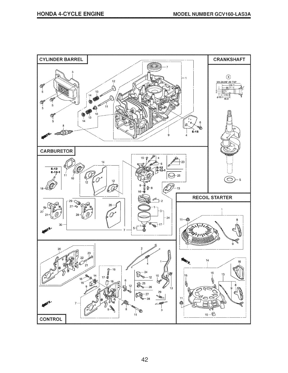
HONDA 4-CYCLE ENGINE MODEL NUMBER GCV160-LAS3A
CYLINDER BARREL I /
F
CARBURETOR !
CRANKSHAFT
®
3;8-24UNF 2B TAP
_ 1357_
_86,7
0525
42

HONDA 4=CYCLE ENGINE MODEL NUMBER GCV160=LAS3A
CYLINDER BARREL
KEY PART
NO. NO.
1 12000-ZOL-406
12000-ZOL-840
3 12310-ZOJ-000
12311 -ZLS-D00
12311 -ZL8-000
4 12355-ZL8-000
5 90013-883-000
6 90014-952-000
7 91201-ZL8-003
8 98079-55846
10 12209-ZM0-003
11 14711-ZL8-000
14711 -ZOJ-000
14711 -ZOJ-800
12 14721 -ZL8-000
13 14751 -ZLS-000
14 14771 -ZOJ-000
DESCRIPTION
Cylinder Assembly
Cylinder Assembly
Cover, Cylinder Head
Cover, Head
Cover, Head
Cover, Breather
(Breather Valve Assembly)
Bolt, Flange (#6 x 12)
(CT200)
Bolt, Flange (#6 x 14)
(CT200)
Oil Seal (25.4 x 62 x 6)
Spark Plug (BPR5ES)
(NGK)
Seal, Valve Stem
Valve, Intake
(Technostar)
Valve, Intake (Rocknel)
Valve, Intake
Valve, Exhaust
Spring, Valve
Retainer, Valve Spring
CARBURETOR
KEY PART
NO. NO.
1 16010-883-015
2 16013-ZL1-003
3 16015-ZOL-881
5 16028-ZE0-005
16028-ZK7-$91
7 16100-ZOL-852
8 16155-ZM0-013
9 16166-ZM0-003
10 16211 -ZLS-000
11 16212-ZL8-000
13 16228-ZL8-000
15 93500-05006-0H
16 99101-124-0600
99101-124-0620
99101-124-0650
26 16951-ZOL-000
DESCRIPTION
Gasket Set
Float Set
Chamber Set, Float
Screw Set
Screw Set
Carburetor Assembly
(BB62Z B)
Valve, Float
Nozzle, Main
Insulator, Carburetor
Gasket, Insulator
Gasket, Carburetor
Screw, Pan (#5 x 6)
Jet, Main (#60)
Jet, Main (#62)
Jet, Main (#65)
Guide, Air
CONTROL
KEY PART
NO. NO. DESCRIPTION
1 16551-ZM0-010 Arm, Governor
2 16555-ZOL-801 Rod, Governor
3 16561-ZOL-000 Spring, Governor
4 16562-ZM0-000 Spring, Throttle Return
10 90015-ZE5-010 Bolt, Governor Arm
13 94050-06000 Nut, Flange (6 mm)
15 93892-04012-00 Screw, Washer Head
(#4 x 12)
16 94103-04000 Washer, Plain (4 mm)
CRANKSHAFT
KEY PART
NO. NO. DESCRIPTION
3 13310-ZM0-610 Crankshaft
5 90402-ZL8-000 Washer, Thrust
RECOIL STARTER
KEY PART
NO. NO. DESCRIPTION
1 28400-Z0L-V20ZA Starter Assembly,
Recoil, "NHI" (Long Rope)
(Black)
8 28461-ZL8-003 Grip, Recoil Starter
9 28462-Z0L-V20 Rope, Recoil Starter,
"Long Type" (Black)
11 90201-ZM0-000 Nut, Flange (6 mm)
43
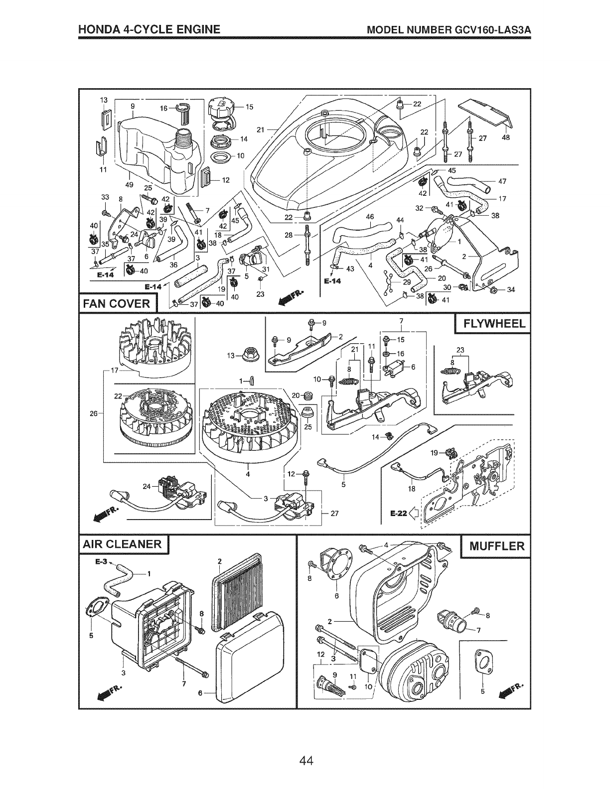
HONDA 4=CYCLE ENGINE MODEL NUMBER GCV160=LAS3A
/
9 _ 15
21
14 27 48
33
49
8
45
12 47
AiR CLEANER !
7
iMUFFLER
44
HONDA 4=CYCLE ENGINE MODEL NUMBER GCV160=LAS3A
FAN COVER
KEY PART
NO. NO.
6 16950-ZOY-003
7 16952-ZA8-800
8 16961-ZOL-900
9 17511-ZOL-030
10 17514-ZOL-000
11 17516-ZOL-000
12 17532-ZOL-000
13 17533-ZOL-000
14 17534-ZOL-000
15 17620-ZOJ-800
16 17636-ZOL-000
21 19610-ZOL-861
19610-ZOL-861
19610-ZOL-861
19610-ZOL-861
22 19619-ZL8-300
24 90013-883-000
25 90015-883-000
27 90043-ZL8-000
28 90043-ZL8-000
33 93913-25220
35 91424-Z8B-821
36 91427-Z8B-821
40 95002-40800-08
42 95002-41200-08
MUFFLER
KEY PART
NO. NO.
1 18310-ZM0-000
2 18321-ZOL-J00
18321-ZOL-J01
3 90004-ZL8-000
4 90013-883-000
5 18381-ZL8-305
9 18350-ZL8-000
10 18356-ZL8-000
11 90055-ZE1-000
12 06180-ZOJ-000
DESCRIPTION
Petcock Assembly
Filter, Fuel
Stay, Fuel Petcock
Tank, Fuel
Seal, Fuel Filler Neck
Clip, Tank Mounting
Rubber A, Tank Mounting
Rubber B, Tank Mounting
Nut, Tank Mounting
Cap Assembly, Fuel Tank
Gauge, Fuel Level
ZC Cover Assembly, Fan
"T89" (Craftsman Red)
ZA Cover Assembly, Fan
"T89" CNH1 ") (Black)
ZD Cover Assembly, Fan
"T93" (Husqvarna Grey)
ZE Cover Assembly, Fan
"T98" (M.T.D. Red)
Collar, Fan Cover
Bolt, Flanged (#6 x 12)
(CT200)
Bolt, Flanged (#6 x 28)
(CT200)
Bolt, Stud (H=42.5mm)
Bolt, Stud (H=42.5mm)
Screw, Tapping (PO)
(#5 x 12)
Tube, Fuel Tank
Tube, Fuel (7.3 x 160)
Clip, Tube (D8)
Clip, Tube (D12)
DESCRIPTION
Muffler
Protector, Muffler
(S/N 1243452 and below)
Protector, Muffler
(S/N 1243453 and above)
Bolt, Flange #6 x 79
(CT200)
Bolt, Flange #6 x 12
(CT200)
Gasket, Muffler
Attester, Spark
Plate, Attester Number
Screw, Tapping #4 x 6
Kit, Spark Arrester
FLYWHEEL
KEY PART
NO. NO.
1 13331-357-000
3 30500-ZL8-014
4 31105-ZM0-000
5 32195-ZM0-800
6 35120-ZM0-003
8 75113-ZM0-000
10 90014-952-000
11 90018-ZE1-000
12 90018-ZE1-000
13 90201-ZOT-800
14 51125-ZOL-003
90681-959-003
15 93892-04012-00
16 94103-04000
21 75110-ZOY-000
25 91601-ZOL-300
AiR CLEANER
KEY PART
NO. NO.
1 15721-ZM0-000
2 17211-ZL8-023
3 17220-ZM0-010
17220-ZM0-020
17220-ZM0-030
5 17228-ZM0-000
6 17231-ZOL-030
17231-ZOL-040
17231-ZOL-050
7 90003-ZM0-010
DESCRIPTION
Key, Special, Woodruff
(25 x 18)
Coil Assembly, Ignition
Flywheel Assembly
Wire, Stop Switch
Switch Assembly,
Engine Stop (NC)
Spring, Brake Lever
Bolt, Flange (#6 x 14)
(CT200)
Bolt, Flange (#6 x 23)
(CT200)
Bolt, Flange (#6 x 23)
(CT200)
Nut, Special (14 mm)
Holder, Wire (Fastex)
Clip A, Cable (3.8mm)
(Black) (NIFCO)
Screw, Washer Head
(#4 x 12)
Washer, Plain (4 mm)
Brake Sub Assembly
Grommet, Brake Plate
DESCRIPTION
Tube, Breather
Element, Air Cleaner
Case Assy., Air Cleaner
(S/N 1167575 and below)
Case Assy., Air Cleaner
(S/N 1167576-1239013)
Case Assy., Air Cleaner
(S/N 1239014 and above)
Gasket, Air Cleaner
Cover, Air Cleaner
(S/N 1167575 and below)
Cover, Air Cleaner
(S/N 1167575 and below)
Cover, Air Cleaner
Bolt, Flange (#6 x 85)
(CT200)
45
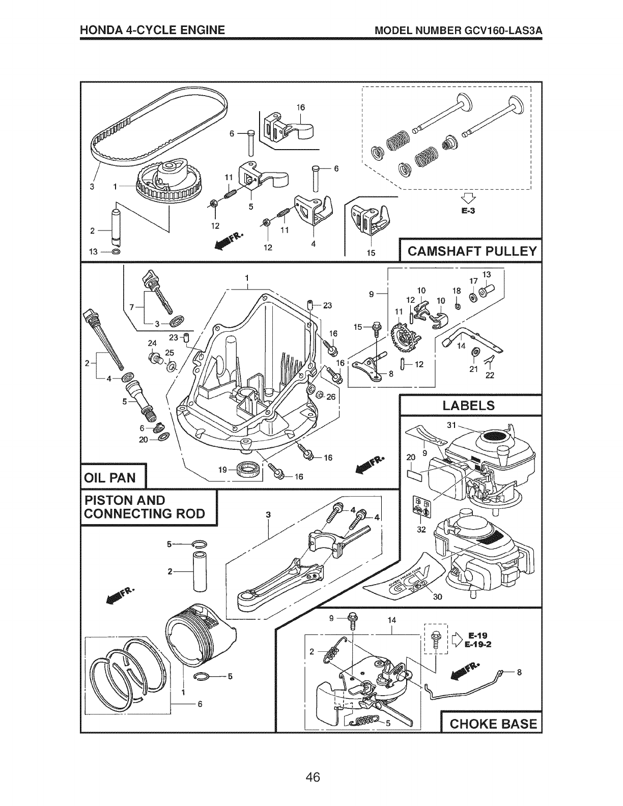
HONDA 4-CYCLE ENGINE MODEL NUMBER GCV160-LAS3A
13 ---_
, }
I '
t
i t
I t
t
/@
15 CAMSHAFT PULLEY
;--_ ' _"_ _'_'// /-_) ' l LABELS
CONNECTING ROD s _J/__, I _[._J _;L_XZT
= /. '32
--- "---.JE__ CHOKE BASE
46
HONDA 4=CYCLE ENGINE MODEL NUMBER GCV160=LAS3A
CAMSHAFT PULLEY
KEY PART
NO. NO.
1 14320-ZL8-010
2 14324-ZL8-000
3 14400-Z0J-014
6 14461-ZL8-000
11 90112-333-000
12 90206-001-000
13 91301 -ZM0-V31
15 14431 -Z0J-000
16 14441 -Z0J-000
DESCRIPTION
Pulley, Camshaft
Shaft, Cam Pulley
Belt, Timing
(84HU7 G-200)
Shaft, Rocker Arm
Screw, Tappet Adjusting
Nut, Tappet Adjusting
O-Ring (6.8 x 1.9) (ARAI)
Rocker Arm, Intake Valve
Rocker Arm,
Exhaust Valve
OiL PAN
KEY PART
NO. NO.
1 11300-ZM0-811
2 15650-ZM0-801
4 15625-ZE6-000
5 15631-ZM0-000
6 15639-ZM0-000
8 16508-ZM0-010
9 16510-ZM0-010
10 16511 -ZL8-000
11 16512-ZM0-000
12 16513-ZE1-000
13 16531-ZE1-000
14 16541 -ZM0-000
15 90014-952-000
16 90121-952-000
17 90451-ZE1-000
18 90602-ZE1-000
19 91202-ZL8-003
20 91356-MA6-005
21 94101-068000
22 94251-08000
23 94301-08200
DESCRIPTION
Pan Assembly, Oil
Gauge Assembly,
Oil Level
Gasket, Oil Filler Cap
Extension, Oil Filler
Lock Washer, Extension
Shaft, Governor Holder
Governor Assembly
Weight, Governor
Holder, Governor Weight
Pin, Governor Weight
Slider, Governor
Shaft, Governor Arm
Bolt, Flange (#6 x 14)
(CT200)
Bolt, Flange (#6 x 25)
(CT200)
Washer, Thrust (6 mm)
Clip, Governor Holder
Oil Seal (28 x 41.25 x 6)
O-Ring (14.8 x 2.4) (NOK)
Washer, Plain (6 mm)
Pin, Lock (8 mm)
Pin, Dowel (#8 x 20)
PISTON ICONNECTING ROD
KEY PART
NO. NO.
1 13101-Z2A-010
2 13111-ZE0-000
3 13200-ZOJ-000
4 90001-ZE1-000
5 90551-ZE0-000
6 13010-ZOL-014
DESCRIPTION
Piston
Pin, Piston
Connecting Rod Assembly
Bolt, Connecting Rod
Clip, Piston Pin (13 mm)
Ring Set, Piston, Standard
(Teikoku)
LABELS
KEY PART
NO. NO. DESCRIPTION
9 87528-ZOL-V20 Mark, Choke Indication
20 87114-ZH7-821 Label, Warning
30 87101-Z8B-000 Mark, Emblem (GCV160)
31 87169-Z8E-000 Mark, Recoil Cover
32 87524-Z8B-000 Mark, Caution,
Fuel Petcock
CHOKE BASE
KEY PART
NO. NO.
2 16592-Z2D-800
5 16614-Z2D-800
8 16632-ZOL-801
9 90022-888-010
14 16610-Z2D-801
16610-Z2D-802
DESCRIPTION
Spring, Return
Spring, Choke Lever
Rod, Stop
Bolt, Flange (#6 x 20)
(CT200)
Lever Assembly, Choke
Lever Assembly, Choke
47

NEED HORE HELP?
Y@/ll i%@ the answer and too:re on _anage_yhO_eoCO_ _ for free!
o Find this and a[[ your other product manuals online.
o Get answers from our team of home experts.
o Get a personalized maintenance plan for your home.
o Find information and tools to help with home projects.
brought to yon by Sears
Your Home
For repair - in your home - of all major brand appliances,
lawn and garden equipment, or heating and cooling systems,
no matter who made it, no matter who sold it!
For the replacement parts, accessories and
owner's manuals that you need to do-it-yourself.
For Sears professional installation of home appliances
and items like garage door openers and water heaters.
1-800-4-MY-HOME ® Anytime, day or night
(1-800-469-4663) (U.S.A. and Canada)
www.sears.com www.sears.ca
Our Home
For repair of carry-in products like vacuums, lawn equipment,
and electronics, call or go on-line for the nearest
Sears Parts and Repair Center.
1-800-488-1222 Anytime, day or night (U.S.A. only)
www.sears.com
To purchase a protection agreement (U.S.A.)
or maintenance agreement (Canada) on a product serviced by Sears:
1-800-827-6655 (U.S.A) 1-800-361-6665 (Canada)
Para pedirservicio de reparaci6n Au Canada pourservice en fran£ais:
a domicilio,y paraordenar piezas: 1-800-LE-FOYERMc
1-888-SU-HOGAR® (1-800-533-6937)
(1-888-784-6427) www.sears.ca
Sears :!
© SearsBrands, LLC
® Registered Trademark /TMTrademark /sm Service Mark of Sears Brands, LLC
® Marca Registrada /TMMarca de Fabrica /SMMarca de Servicio de Sears Brands, LLC
MCMarque de commerce /MDMarque d6pos@e de Sears Brands, LLC
438096 Rev. 3 06.28. BY PrintedinU.S.A.
