Craftsman Lawnsweeper 486 242211 Users Manual
LAWNSWEEPER 486.242211 24221e
2015-01-05
: Craftsman Craftsman-Lawnsweeper-486-242211-Users-Manual-160939 craftsman-lawnsweeper-486-242211-users-manual-160939 craftsman pdf
Open the PDF directly: View PDF ![]() .
.
Page Count: 20
42" LAWNSWEEPER
Model No's. 486.242211
Owner's Manual
CAUTION:
Before using this product, read this
manual and follow all Safety Rules
and Operating Instructions.
• Safety
• Assembly
• Operation
• Maintenance
• Parts
PRINTEDINU.S.A. FORMNO.40637(REV.3/12/08)
Sears,RoebuckandCo.,HoffmanEstates,IL60179U.S.A.
www.sears.com/craftsman
®
Aerosmith Rocks
STOP
DO NOT RETURN TO STORE
For Missing Parts or Assembly
Questions Call 1-866-576-8388

2
ONE YEAR FULL WARRANTY
Whenassembled,operatedandmaintainedaccordingtothesuppliedinstructions,ifthisCraftsmanLawnsweeperfailsduetoa
defectinmaterialorworkmanshipwithinoneyearfromthedateofpurchase,call1-800-4-MY-HOMEtoarrangeforfreerepair(or
replacementifrepairprovesimpossible).
Thiswarrantyisvoidifthisproductiseverusedforcommercialorrentalpurposes.
ThiswarrantyappliesonlywhilethisproductisusedintheUnitedStates.
Thiswarrantygivesyouspeciclegalrights,andyoumayalsohaveotherrightswhichvaryfromstatetostate.
Sears,RoebuckandCo.,Dept.817WA,HoffmanEstates,IL60179
Anypowerequipmentcancauseinjuryifoperatedimproperlyoriftheuserdoesnotunderstandhowtooperatetheequipment.
Exercisecautionatalltimes,whenusingpowerequipment.
1. Readthevehicleandsweeperownersmanualsand
knowhowtooperateyourvehicleandsweeperbefore
usingthissweeperattachment.Alwaysinstructother
usersbeforetheyoperatethesweeper.
2. Donotpermitchildrentooperatesweeper.
3. Donotpermitanyonetorideonsweeper.
4. Neverattachthehopperropetoanypartofyourbody
orclothing!Neverholdontotheropewhiletowingthe
sweeper!Attachtheropetothetowingvehicletokeep
it away from wheels and rotating parts.
5. Operate the sweeper at reduced speed on rough
terrain, near ditches and on hillsides to prevent loss of
control.
6. Vehiclebrakingandstabilitymaybeaffectedwith
theattachmentofthissweeper.Donotllsweeper
tomaximumcapacitywithoutcheckingthecapability
of the towing vehicle to safely pull and stop with the
sweeper attached. Stay off of steep slopes.
7. Stopandinspectvehicleandsweeperfordamage
afterstrikinganobject.Repairanydamagebefore
continuing operation.
8. Keepsweeperawayfromre.Excessiveheatcan
damagethebrushesandhopperbagandcouldcause
thebaganditscontentstoburn.
9. Beforestoringthesweeper,alwaysemptythehopper
bagtoavoidspontaneouscombustion.
10.Followmaintenanceandlubricationinstructionsas
outlined in the maintenance section of this manual.
Lookforthissymboltopointoutimportantsafetyprecautions.Itmeans—Attention!!
Become alert!! Yoursafetyisinvolved.
MaintenanceSchedule ..................................................13
Storage ..........................................................................13
ServiceandAdjustments ...............................................14
Troubleshooting .............................................................14
RepairPartsIllustration ................................................. 16
RepairPartsList ............................................................17
PartsOrdering/Service ....................................BackCover
Safety Rules .................................................................... 2
AccessoriesandAttachments .........................................3
CartonContents ..............................................................3
FullSizeHardwareChart ................................................ 4
SweeperAssemblyInstructions ......................................5
HopperAssemblyInstructions .........................................8
Operation .......................................................................12
MODELNUMBER: 486.242211
SERIALNUMBER: __________________
DATEOFPURCHASE: __________________
SAFETY
WARRANTY
TABLE OF CONTENTS
Themodelandserialnumberswillbefoundonadecal
attached to the lawnsweeper.
Youshouldrecordboththeserialnumberandthedateof
purchaseandkeepinasafeplaceforfuturereference.
3
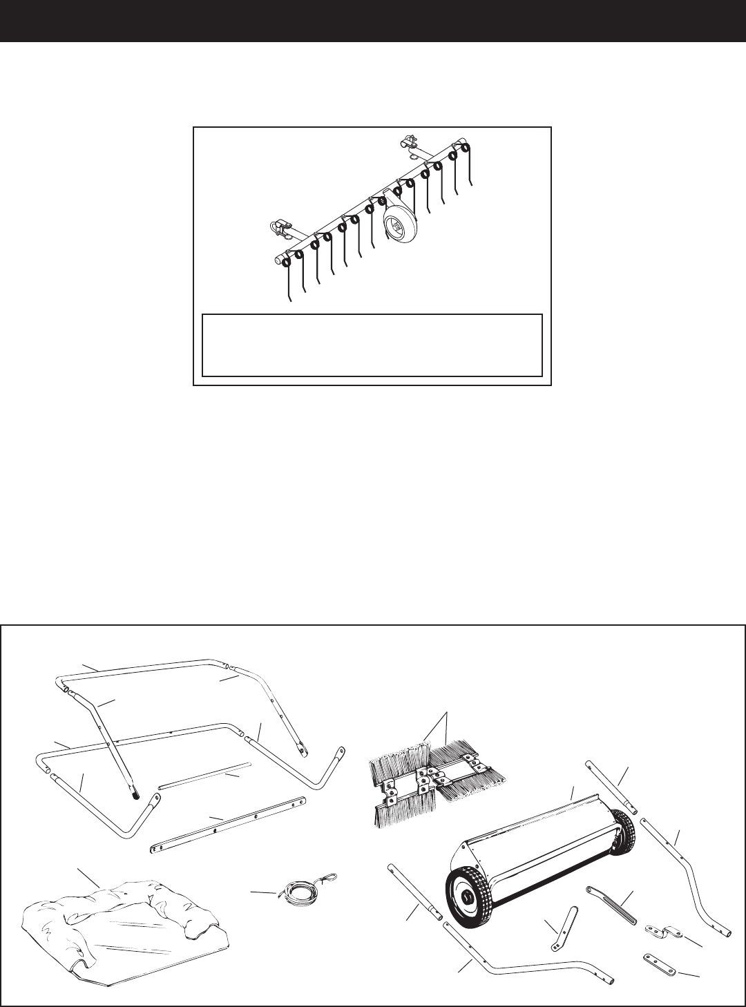
CARTON CONTENTS (LoosePartsinCarton)
ACCESSORIES AND ATTACHMENTS
TheFrontMountDethatcher,Model486.24219attaches
to the lawn sweeper to help loosen and remove dead
grass and thatch from the lawn while sweeping.
Theseaccessorieswereavailablewhentheunitwaspurchased.TheyarealsoavailableatmostSearsretailoutletsand
servicecenters.MostSearsstorescanorderrepairpartsforyouwhenyouprovidethemodelnumbersofyourtractorand
sweeper
1. SweeperHousingAssembly
2. BagArmTube(2)
3. LeftHitchTube
4. HitchBracket
5. HitchBracket(Straight)
6. HeightAdjustmentStrap
1
2
3
4
5
6
7
8
2
16
15
10 10
12
13
11
11
12
14
9
7. HeightAdjustmentHandle
8. RightHitchTube
9. BrushAssembly(2)
10.UpperHopperSideTube(2)
11.RearHopperTube(2)
12.LowerHopperSideTube(2)
13.HopperSupportRod(2)
14.BagFrameStrap
15.HopperBag
16.Rope
4
HARDWARE PACKAGE CONTENTS
A B C DF G
I
J
M
N
K
YZ
L
Q
TS U
SHOWN FULL SIZE
NOT SHOWN FULL SIZE
P
O
E
R
V W X
REF qTY DESCRIPTION
A 2 HexBolt,5/16x2-1/2"Lg.
B2 HexBolt,5/16x2"Lg.
C 4 CarriageBolt,5/16"x1-1/2"
D 1 HexBolt,5/16x1-1/4"Lg.
E 2 HexBolt,5/16"x1"
F1 CarriageBolt,5/16"x1"
G4 HexBolt,1/4"x1"
I4 NylockNut,1/4"
J 11 NylockNut,5/16"
K 4 FlatWasher,5/16"
L 1 Star Washer
M 1 HairCotterPin,1/8"
N 8 HairCotterPin,3/32"
REF qTY DESCRIPTION
O2 ClevisPin,3/8"x1/2"
P 2 ClevisPin,1/4"x1-1/8"
Q2 ClevisPin,1/4"x1-3/4"
R2 ClevisPin,3/8"x3"
S1 PivotBushing
T 1 Spacer Bushing
U 2 HitchSpacer,3/4"
V 2 VinylCap
W1Grip
X1 Knob,Plastic
Y 1 HitchPin
Z4 PlasticPlug
5
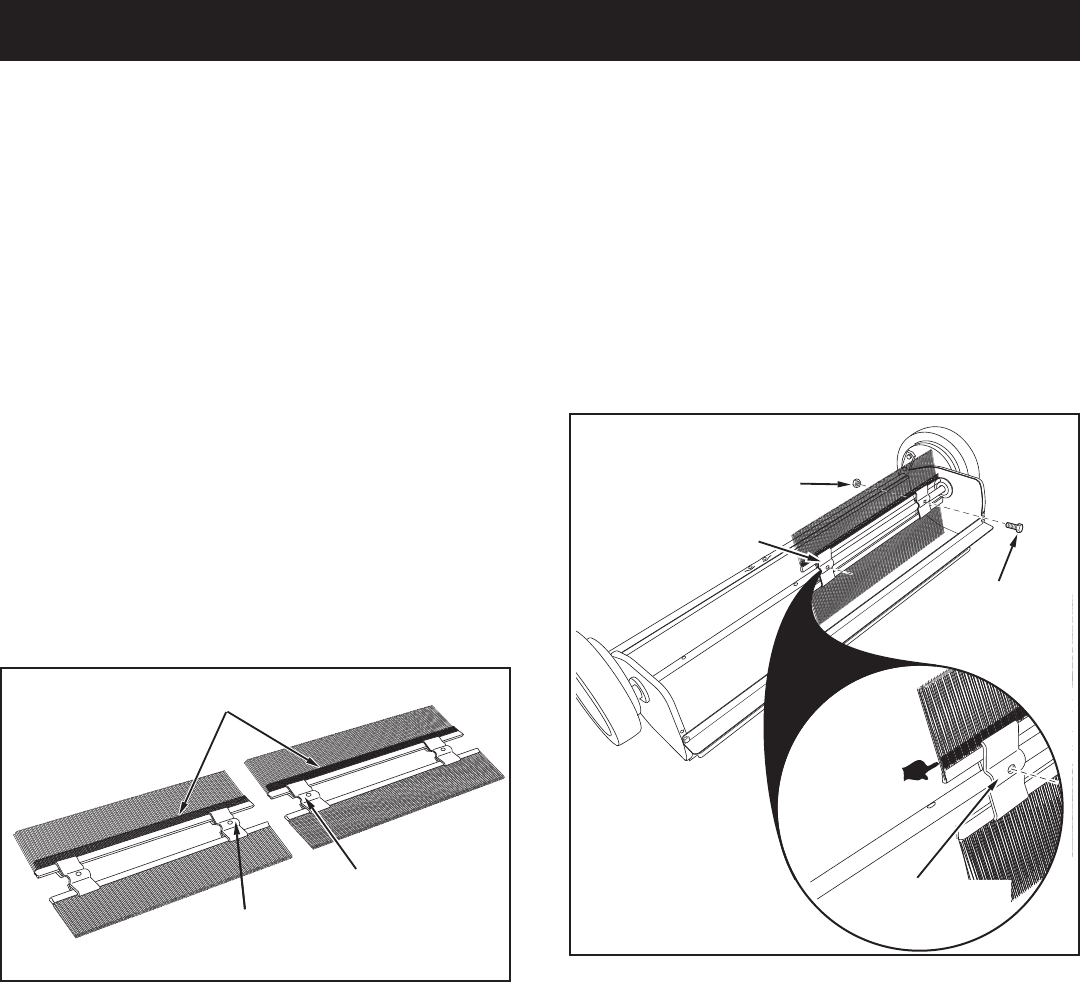
STEP 2: (SEE FIGURE 2)
• Attachthebrushassemblywiththeredbrushretainer
totherightendofthebrushshaftusingtwo1/4"x
1"hexbolts(G)and1/4"nylocknuts(I).Thebrush
retainermarkedwithredinkmustbeplacedtothe
middle of the sweeper.
FIGURE 1
TOOLS REqUIRED FOR ASSEMBLY
(2)7/16"OpenEndorBoxEndWrenches
(2)1/2"OpenEndorBoxEndWrenches
ASSEMBLY
REMOVE PARTS FROM CARTON
• Toprotectpaintedparts,laythemoncardboardora
mat.
• Removethesweeperhousing,theloosepartsandthe
hardwarepackagefromthecarton.Layouttheparts
andhardwareasshownonpages3and4.
STEP 1: (SEE FIGURE 1)
• Eachbrushassemblyhasonebrushretainer
markedwitheitherredorblackink.Layoutthebrush
assembliesasshownsothatthebrushretainers
markedwithinkareinthemiddlewiththeredoneon
therightandtheblackoneontheleft.
OVERLAP BRISTLES
BRUSH RETAINER
MARKED BLACK
BRUSH RETAINER
MARKED RED
IMPORTANT:Theoverlapbristlesatthebottomofeach
brushhelpsupportthebacksideofthebrushforbetter
sweeper performance. Be sure the sweeper is turned
asshowningures2and3tocorrectlyassemblethe
brushes.
BRUSH RETAINER
MARKED RED
OVERLAP
BRISTLES
1/4" x 1"
HEX BOLT (G)
1/4" NYLOCK NUT (I)
BRUSH RETAINER
MARKED RED
FIGURE 2
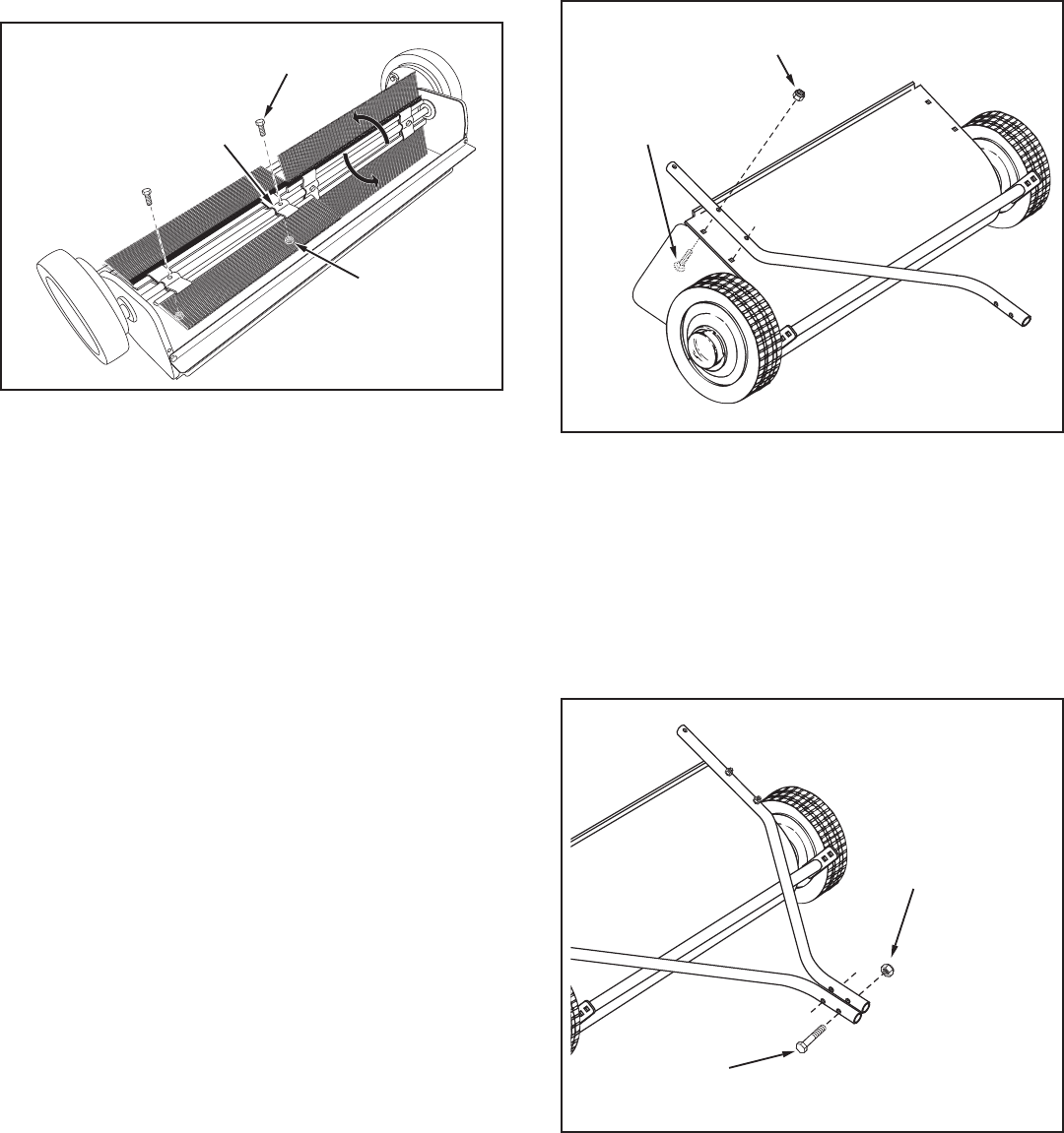
6
FIGURE 4
STEP 4: (SEE FIGURE 4)
• Cutofftheplastictiethatholdstheheightadjustment
tubeinplace.
• AssembletheR.H.hitchtubetothesweeperhousing
usingtwo5/16"x1-1/2"carriagebolts(C),andtwo
5/16"nylocknuts(J).Do not tighten yet. Repeat for
theL.H.hitchtube.
FIGURE 3
STEP 3: (SEE FIGURE 3)
• Attachthebrushassemblywiththeblackbrush
retainertotheleftendofthebrushshaftusingtwo
1/4"x1"hexbolts(G)and1/4"nylocknuts(I).The
brushretainermarkedwithblackinkmustbeplaced
to the middle of the sweeper.
• Turnawheeltorotatethebrushes.(Thewheelsdrive
thebrushesinonedirectiononly.)Theoverlapbristles
shouldbeonthebacksideofthebrushasitrotates.
1/4" x 1"
HEX BOLT (G)
1/4" NYLOCK NUT (I)
BRUSH RETAINER
MARKED BLACK
5/16" x 1-1/2"
CARRIAGE BOLT (C)
5/16" NYLOCK NUT (J)
STEP 5: (SEE FIGURE 5)
• Fastenthehitchtubestogetherusingtwo5/16"x
2-1/2"hexbolts(A)and5/16"nylocknuts(J).Do not
tighten yet.
5/16" x 2-1/2"
HEX BOLT (A)
5/16"
NYLOCK NUT (J)
FIGURE 5
7
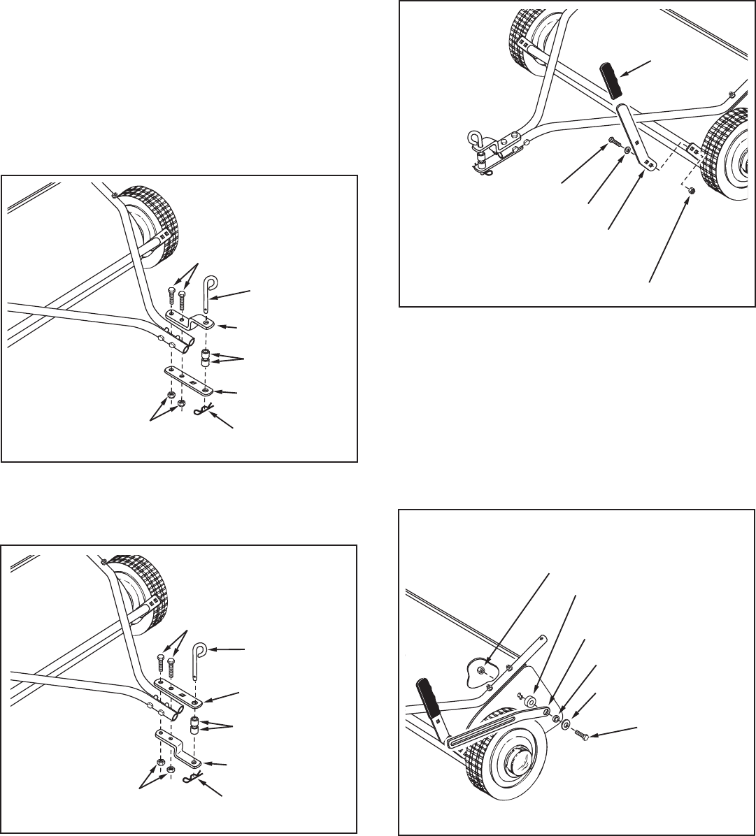
STEP 6: (SEE FIGURE 6 AND 7)
If your tractor hitch has 10" to 13" ground clearance
refer to gure 6. If your tractor hitch has 8" to 10"
ground clearance refer to gure 7.
• Assemblethehitchbracketstothehitchtubesusing
two5/16"x2"hexbolts(B)and5/16"nylocknuts(J).
Theboltsshouldstraddlethefronthitchtubebolt.Do
not tighten yet.
• Atthis time tightenthe fourboltsfasteningthe hitch
tubestothesweeperhousing.Next,tightenthetwobolts
fasteningtheendsofthehitchtubestogether.Finally,
tightenthetwoboltsfasteningthehitchbracketstothe
hitchtubes.
• Assemblethehitchpin(Y),two3/4"hitchspacers(U)
andthe1/8"haircotterpin(M)tothehitchbrackets.
5/16" x 2"
HEX BOLT (B)
5/16" NYLOCK
NUT (J)
3/4" SPACER (U)
HITCH BRACKET
HITCH BRACKET
(STRAIGHT)
1/8" HAIR
COTTER PIN (M)
HITCH PIN (Y)
5/16" x 2"
HEX BOLT (B)
5/16" NYLOCK
NUT (J)
3/4" SPACER (U)
HITCH PIN (Y)
HITCH BRACKET
(STRAIGHT)
1/8" HAIR
COTTER PIN (M)
HITCH BRACKET
FIGURE 6
FIGURE 7
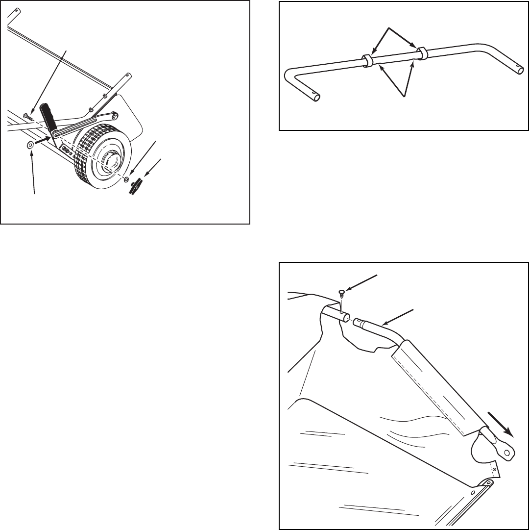
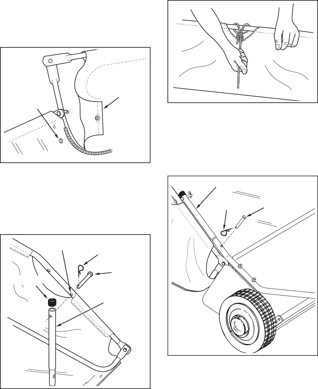
STEP 7: (SEE FIGURE 8)
• Assembletheheightadjustmenthandletotheinside
ofthebracketontheendoftheheightadjustment
tube.Usetwo5/16"x1"hexbolts(E),5/16"at
washers(K)and5/16"nylocknuts(J).Tighten.
• Assemblethegrip(W)ontotheheightadjustment
handle.
5/16" NYLOCK NUT (J)
HEIGHT
ADJUSTMENT
HANDLE
GRIP (W)
5/16" FLAT WASHER (K)
5/16" x 1" HEX BOLT (E)
FIGURE 8
STEP 8: (SEE FIGURE 9)
• Assembleontoa5/16"x1-1/4"hexbolt(D)inthe
orderlisted,a5/16"atwasher(K),thepivotbushing
(S),theheightadjustmentstrapandthespacer
bushing(T).Inserttheboltthroughtheupperpartof
thedoubleholeintheendofthesweeperhousing
andsecureitwitha5/16"nylocknut(J).Tighten.
PIVOT BUSHING (S)
5/16" NYLOCK NUT (J)
SPACER BUSHING (T)
5/16" FLAT WASHER (K)
5/16" x 1-1/4"
HEX BOLT (D)
HEIGHT ADJUSTMENT
STRAP
FIGURE 9
8
ASSEMBLY OF HOPPER BAG
STEP 10: (SEE FIGURE 11 AND 12)
• Turnarearhoppertubesothatthebraceholesinthe
middleofthetubeface down.Slidethetubethrough
the two loops sewn to the top rear seam inside the
hopperbag.
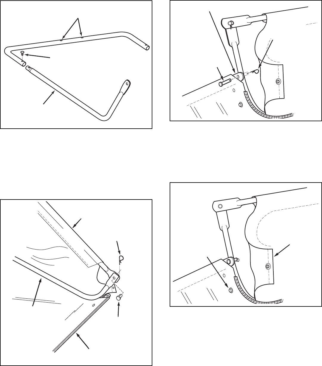
STEP 9: (SEE FIGURE 10)
• Placethestarwasher(L)betweentheheight
adjustmenthandleandtheheightadjustmentstrap.
Insertthe5/16"x1"carriagebolt(F)throughthe
heightadjustmenthandle,thestarwasherandthe
heightadjustmentstrap.Assemblea5/16"atwasher
(K)andtheplasticknob(X)ontotheendofthebolt.
5/16" FLAT
WASHER (K)
5/16" x 1"
CARRIAGE BOLT (F)
PLASTIC KNOB (X)
STAR WASHER (L)
(between strap and handle)
REAR HOPPER TUBE
(brace holes on bottom)
INNER BAG LOOPS
• Insertthetwoupperhoppersidetubesthroughthe
stitchedapsoneachsideofthehopperbag.
• Assembletheendsoftherearhoppertubeontothe
endsoftheupperhoppersidetubes.Fastentogether
usingplasticplugs(Z).
UPPER HOPPER
SIDE TUBE
PLASTIC PLUG (Z)
FIGURE 10
FIGURE 11
FIGURE 12
9
STEP 11: (SEE FIGURE 13 AND 14)
• Turnthesecondrearhoppertubesothatthebrace
holesinthemiddleofthetubeface up.Assemble
theendsoftherearhoppertubeontotheendsofthe
lowerhoppersidetubes.Fastentogetherusingplastic
plugs(Z).
STEP 12: (SEE FIGURE 15 AND 16)
• Insertthebagframestrapintothestitchedsleeve
alongthefrontedgeofthebagbottom.
• Assemblethebagframestraptothelowerhopper
sidetubesusingtwo1/4"x1-1/8"clevispins(P)and
3/32"haircotterpins(N).
LOWER
HOPPER
SIDE TUBE
PLASTIC PLUG (Z)
REAR HOPPER TUBE
(brace holes on top)
• Placetheassembledlowerhoppertubesintothe
bottomofthehopperbag
• Attachtheendsofthelowerhoppersidetubestothe
insideoftheupperhoppersidetubesusingtwo3/8"
x1/2"clevispins(O)insertedfromtheinside,andtwo
3/32"haircotterpins(N).
LOWER HOPPER
SIDE TUBE
HOPPER BAG
BOTTOM
UPPER HOPPER
SIDE TUBE
3/8" x 1/2"
CLEVIS PIN (O)
3/32" HAIR
COTTER PIN (N)
1/4" x 1-1/8"
CLEVIS PIN (P)
3/32" HAIR
COTTER PIN (N)
BAG FRAME STRAP
• Securethebagcornersaroundthelowerhopperside
tubesbysnappingthebagapstothebagbottomon
bothsides.
SNAP
FLAP
FIGURE 13
FIGURE 14
FIGURE 15
FIGURE 16
10
STEP 13: (FIGURE 17)
IMPORTANT: Do notoverbendthesupportrods
duringthefollowingstep.Overbendingwillcausethe
steel rods to loose supporting tension.
• Tipthehopperontoit'sbacktoassemblethetwo
hoppersupportrods.Placetheendsofeachrodinto
theupperandlowerrearhoppertubes,bendingthe
rodjustenoughtotintotheholesinthetubes.
SNAP
FLAP
STEP 14: (FIGURE 18)
• Inserta3/8"x3"clevispin(R)throughthelower hole
ineachupperhoppersidetube.Nextassembleabag
armtubeontoeachclevispinandsecureitwitha
3/32"haircotterpin(N).
• Assembleavinylcap(V)ontotheendofeachbag
armtube.
LOWER HOLE 3/32" HAIR
COTTER PIN (N)
3/8" x 3"
CLEVIS PIN (R)
BAG ARM TUBE
VINYL CAP (V)
STEP 15: (SEE FIGURE 19 AND 20)
• Securetheropetothetopcenterofthehopperbag
frame.
• Toassemblethehopperbagtothesweeper,slide
theendsofthebagarmtubesintotheendsofthe
sweeper'shitchtubesandsecurewithtwo1/4"x
1-3/4"clevispins(Q)and3/32"haircotterpins(N).
BAG ARM TUBE
1/4" x 1-3/4"
CLEVIS PIN (Q)
3/32" HAIR
COTTER PIN (N)
FIGURE 17
FIGURE 18
FIGURE 19
FIGURE 20
11
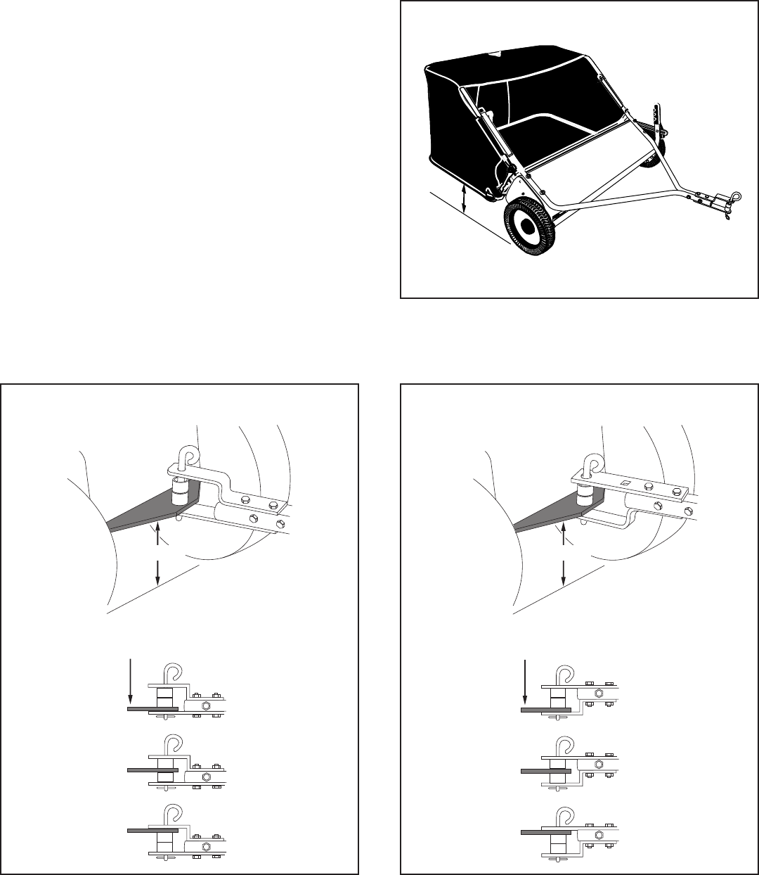
STEP 16: (SEE FIGURE 21, 22 AND 23)
• Placethetractorandsweeperonaatlevelsurface.
• Setthesweeperheightadjustmenthandletoabout
themiddleofitsadjustmentrange.
• Attachthesweeperhitchbracketstothetractorhitch,
arrangingthe3/4"spacerssothatthebottomofthe
sweeperbagisapproximatelyleveland5"to7"above
theground.Seegure22fortractorhitchesthatare
10"to13"abovetheground.Seegure23fortractor
hitchesthatare8"to10"abovetheground.
IMPORTANT: Forbestperformance,thebottomofthe
sweeperbagshouldbeapproximatelyleveland5"to7"
offthegroundasshowningure21.
Tractor hitches with 8" to 10" ground clearance.
Tractor hitches with 10" to 13" ground clearance.
TRACTOR HITCH
8"-10"
TRACTOR HITCH
10"-13"
5" Min.
Aerosmith Rocks
FIGURE 21
FIGURE 22 FIGURE 23
12
KNOW YOUR SWEEPER
CAUTION:Keepsweeperawayfromre.
Excessiveheatcandamagethebrushesand
hopperbagandcouldcausethebagandits
contentstoburn.
CAUTION: Never attach the hopper rope
toanypartofyourbodyorclothing!Never
hold onto the rope while towing the sweeper!
Attach the ropetothetowingvehicletokeep
it away from wheels and rotating parts.
DUMPING OF SWEEPER
• Yoursweepercanbedumpedeasilywithoutgetting
off of the rider or tractor. Simply pull the rope forward
todumpthehopper.Alwaysemptyhopperaftereach
use.
BRUSH HEIGHT ADJUSTMENT
• Toadjustyoursweeperbrushestothebestoperating
height,loosentheadjustmentknobandpushdownon
theheightadjustmentlevertoraisethebrush,orpush
uponthelevertolowerthebrush.Seegure22.Best
adjustmentiswhenthebrushsettingis1/2"downinto
thegrass.Alwaysmowthegrasstoanevenheight
beforesweeping.
SWEEPING SPEED
• Tryastartingspeedofapproximately3m.p.h.(third
gearonmosttractors).Dependingontheconditions,
itmaybenecessarytoadjustthesweepingspeedin
ordertoachievebestresults.
OPERATION
HopperBag Collectsgrassclippings,leavesanddebris.
HopperRope Permitsdumpingofhopperbagfromdriver'sseat.
Windscreen Helpspreventcollectedmaterialfrombeingblownoutofhopperbag.
BagArmTubes Connectsthehopperbagtothesweeperhousing.
HeightAdjustmentHandle Adjuststheoperatingheightofthesweeper.
HeightAdjustmentStrap Holdstheheightadjustmenthandleinpositionwhenlocked.
Knob Lockstheheightadjustmenthandletotheheightadjustmentstrap.
HitchBracket Connectsthesweepertothetowingvehicle.Adjustsforvariousheighttractorhitches.
HOW TO USE YOUR SWEEPER
Aerosmith Rocks
HOPPER BAG
WINDSCREEN BAG ARM
TUBE HEIGHT
ADJUSTMENT
HANDLE
KNOB
HITCH
BRACKETS
HOPPER
ROPE
HEIGHT
ADJUSTMENT
STRAP
HEIGHT
ADJUSTMENT
STRAP
13
MAINTENANCE
MAINTENANCESCHEDULE
Fill in dates as you
complete regular service.
Checkforloosefasteners X
Checkforwornordamagedparts X X
Lubricatebrushshaftbearings X
Lubricatewheelbearings X
CleanSweeper X X
Clean/Lubricatechainandsprockets X
HEX BOLT FLAT WASHER
FLAT WASHER
HEX LOCK NUT
HUB CAP
SPACER
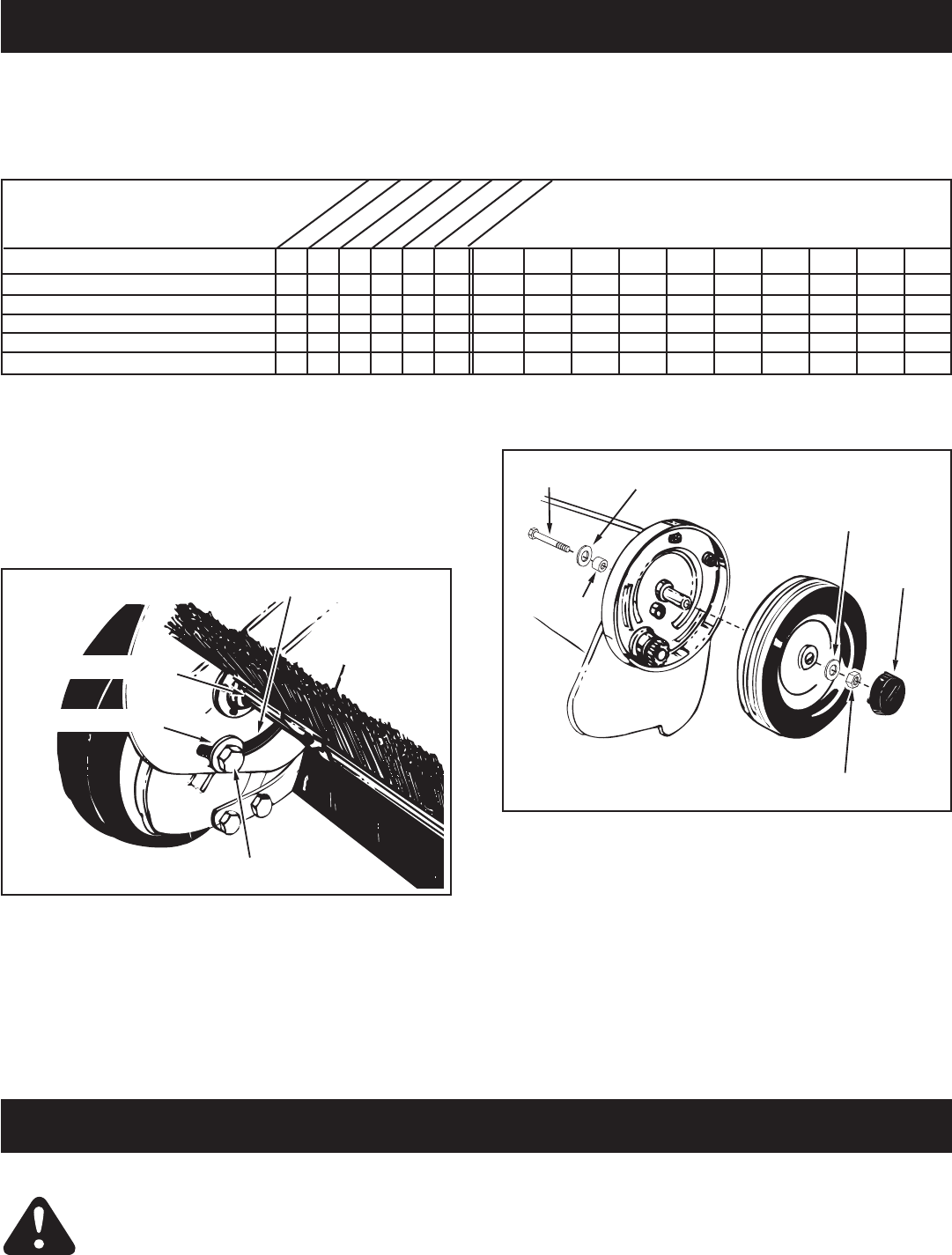
FIGURE 25
• Everytwoyears,removethewheelsandcleanthe
gearsfoundinsidethewheelhousing.Aftercleaning,
lubricatethegearswithanevencoatoflightgrease.
Toremovethewheel,popoffthehubcapandremove
thelocknutandatwasher.Seegure25.
CLEANING
• Cleansweeperhousingwithasoftbrushorcloth.
• Cleandebrisfromhopperbagwithabrushorbroom.
• Removeanymaterialwhichhaswrappedaround
brushesorendsofbrushshaft.
CUSTOMER RESPONSIBILITIES
• Read and follow the maintenance schedule and the
procedures listed in the maintenance section.
Before each use
Aftereachuse
Twiceayear
Everyseason
Before storage
Everytwoyears
ServiceDates
SCHEDULED MAINTENANCE
• Cleanthesweeperaftereachuse.
• Inspectforwornordamagedparts,suchasbrushes
and wheels.
• Lubricatethebrushshaftbearingtwiceayearwitha
fewdropsoflightweightoil.Seegure24.
HEIGHT ADJUSTMENT SLOT
HEX BOLT
OIL BEARINGS HERE
FLAT WASHER
FIGURE 24
• Cleanthesweeperandhopperbagthoroughlytohelp
prevent rust and mildew.
• Tocollapsethehopperbagforstorage,removethetwo
hopper support rods from the rear of the hopper.
• Storeinadryarea.
CAUTION: Before storing the sweeper,
alwaysemptythehopperbagtoavoid
spontaneouscombustion.
STORAGE
14
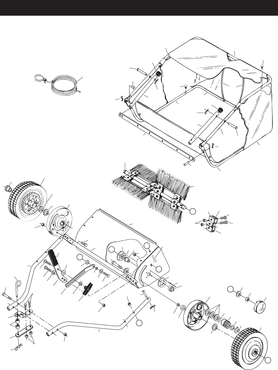
WHEEL GEAR AND PAWL SERVICE
IMPORTANT: Do notremovebothwheelsatthesame
timetoavoidmixingofparts.(TheR.H.andL.H.ratchet
sprocketsarenotinterchangeable.)Make notes on the
positionofwashersandsnapringsduringdisassembly.
• Removeonly one wheel from the sweeper.
• Removetheretainingringsandwasherswhichhold
theratchetgearonthebrushshaft.
• Slidethegearoffofthebrushshaft.(Lookforthe
drivepin,whichmayfalloutofthebrushshaftwhen
theratchetgearisremoved.)Seegure27.
• Toreassemble,insertthedrivepinthroughthehole
neartheendofthebrushshaft.Makesurethepin
slidesbackandfortheasilyintheshaft.
• Lightlygreasetheshaftandlltheratchetgearwith
grease.Assembletheratchetgearbackontothe
shaft.
• Lightlygreasetheaxleandthegearteethonthe
wheel,andthenreassemblethewheel.Thebrushes
should rotate only during forward rotation of the
wheel.Ifthebrushesaredriven(rotated)byboth
forward and reverse rotation of the wheel, the drive
pinisjammingintheratchetgear.Disassembleto
cleanandlubricatethedrivepinandtheratchetgear.
• Removethesecondwheelandrepeattheprocedure.
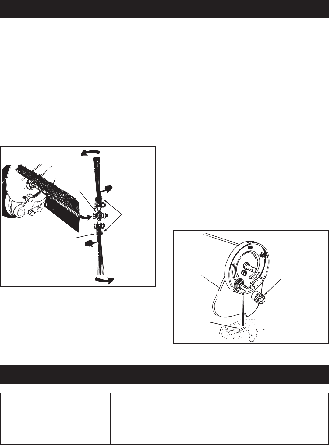
BRUSH REPLACEMENT
NOTE: Brushreplacementshouldbedoneonebrushat
a time.
• Removethehopperbagfromthesweeper.
• Loosenthehexboltsandlocknutsontwosingle
brushretainerswhichclamponebrushtothedouble
brushretainers.Do Not loosenorremovethebolts
whichfastenthedoublebrushretainerstothebrush
shaft.Seegure26.
• Slidethebrushoutoftheretainers,notingonwhich
sideofthebrushthebristlesoverlap.Seegure26.
• Installnewbrush,makingsurethebristlesoverlapon
thesamesideofthebrushasbefore.Seegure26.
FIGURE 27
BRUSH ROTATION
BRUSH ROTATION
OVERLAP
BRISTLES
OVERLAP
BRISTLES
SINGLE
BRUSH
RETAINERS
DOUBLE BRUSH RETAINER
BRUSH
SHAFT
FIGURE 26
• Brushessettoolow.
• Brushesarejammed
• Wheelsarejammed.
Wheelsskidwhensweeping. • Adjust height till brushes are 1/2"
down into grass.
• Stopsweeper.Removeobstruction.
• Removeonewheelatatimetocheck
forobstructionordamage.Referto
ServiceandAdjustmentssection.
SERVICE AND ADJUSTMENTS
TROUBLESHOOTING
RATCHET
GEAR
DRIVE
PIN

15
NOTES
16
PARTS
REPAIR PARTS FOR MODEL 486.242211 - 42" LAWNSWEEPER
1
2
10
7
20
21
22
23
24
25
26
26
27
29
29
29
30 31
32
33
35
36 37
39 41
42
43
43
55
56
60
61
60
61
63
62
3
4
5
66
71
34
9
12
29
65
15
25
52
53
66
44
45
46
44
46
48
50
51
58
58
72
49
53
45
47
59
66
59
66
66
47
16
14
13
54
67
69
69 69
39
57
68
70
A
17
18 19
38
35
11
A
B
B
D
D
C
C
29
29

17
REPAIR PARTS FOR MODEL 486.242211, 42" LAWNSWEEPER
REF PART NO. qTY DESCRIPTION
1 40614 1 HitchTube,R.H.
2 40615 1 HitchTube,L.H.
3 23353 1 Pin,Hitch
4 23368 2 Tube,HitchSpacer
543343 1 HairpinCotter,1/8"#4
7 C-9M5732 8 Rivet,Pop
9 43182 4 Bolt,Hex5/16-18x3/4"
10 66137 1 SweeperHousingAssembly
11 23336 2 Washer, Special
12 66070 1 HeightAdjustmentTubeAssembly
13 43063 2 Bolt,Hex5/16-18x1"
14 25408 1 Bushing, Spacer
15 43840 1 Bolt,Hex5/16-18x1-1/4"
16 44732 1 Washer, Star
17 R19212113 2 Washer,5/8"SAE
18 1629-56 2 Retainer,DustCover
19 44910 2 Bushing, Brush Shaft
20 25850 1 Brush Shaft
21 48557 4 Brush
22 43012 8 Bolt,Hex1/4-20x3/4"Lg.
23 47189 12 Nut,Nylock1/4-20
24 23580 4 Retainer,Brush(Double)
25 23581 8 Retainer,Brush(Single)
26 44008 2 Washer,Flat1-1/8"x.78"x.025"
27 47046 2 DowelPin(Drive)
29 47810 15 Nut,Nylock5/16-18
30 44911 2 Spacer,.39I.D".x1-1/4"O.D.x.5"
31 44006 2 Washer,Flat.849"x.598"x.025"
32 46219 2 Spacer,.78I.D".x1-1/4"O.D.x.5"
33 1650-21 2 Ring,Retaining.594"
34 40001 6 Washer,Shim1-1/8"x.594"x.025"
35 141 4 Washer,Flat1-1/2"x.375"x.062"
36 1038 2 Nut,NylockJam3/8-24Thread
37 2674-32 2 HubCap
38 44961 2 Bolt,Hex3/8-24x3-1/4"Lg.
REF PART NO. qTY DESCRIPTION
39 23400 3 Bushing,Pivot
40 48652 1 Gear,PinionR.H.(notshown)
41 48651 1 Gear,PinionL.H.
42 43661 4 Bolt,Hex1/4-20x1"Lg.
43 64559 2 Ass'y,DustCover
44 48587 2 Tube,HopperFrame(Rear)
45 48466 2 Tube,UpperHopperFrame(Front)
46 48726 2 Tube,LowerHopperFrame(Front)
47 48402 4 PlasticPlug
48 48388 1 HopperBag
49 48366 2 ClevisPin,3/8"x1/2"
50 24949 1 Strap, Bag Frame
51 43926 2 Rod,HopperSupport
52 43737 1 HopperRope
53 44481 2 Cap,Vinyl
54 24979 1 Strap,HeightAdjustment
55 23687 1 Bracket,Hitch
56 24192 1 Bracket,Hitch(Straight)
57 26243 1 Handle,HeightAdjustment
58 40621 2 Tube,BagArm
59 43513 2 Pin,Clevis3/8"x3"
60 44985 2 Wheel&TireAss'y.(withbearings)
61 45088 4 Wheel Bearing
62 44292 2 Bolt,Hex5/16-18x2-1/2"Lg.
63 44180 2 Bolt,Hex5/16-18x2"Lg.
65 43681 4 Bolt,Carriage5/16-18x1-1/2"
66 43055 8 HairpinCotter,3/32"#3
67 43720 1 Knob,Wing5/16-18Thread
68 44326 1 Bolt,Carriage5/16-18x1"
69 43081 4 Washer,Flat5/16"Std.Wrt.
70 43943 1 Grip,HeightAdjust
71 46867 2 ClevisPin,1/4"x1-3/4"Lg.
72 48365 2 ClevisPin,1/4"x1-1/8"
40637 1 OwnersManual

18
NOTES

19
NOTES

® Registered Trademark / TM Trademark / SM Service Mark of Sears Brands, LLC
® Marca Registrada / TM Marca de Fábrica / SM Marca de Servicio de Sears Brands, LLC
MC Marque de commerce / MD Marque déposée de Sears Brands, LLC © Sears Brands, LLC
Get it fixed, at your home or ours!
Your Home
For repair – in your home – of all major brand appliances,
lawn and garden equipment, or heating and cooling systems,
no matter who made it, no matter who sold it!
For the replacement parts, accessories and
owner’s manuals that you need to do-it-yourself.
For Sears professional installation of home appliances
and items like garage door openers and water heaters.
1-800-4-MY-HOME®(1-800-469-4663)
Call anytime, day or night (U.S.A. and Canada)
www.sears.com www.sears.ca
For expert home solutions advice: www.managemyhome.com
Our Home
For repair of carry-in items like vacuums, lawn equipment,
and electronics, call or go on-line for the location of your nearest
Sears Parts & Repair Service Center
1-800-488-1222 (U.S.A.) 1-800-469-4663 (Canada)
Call anytime, day or night
www.sears.com www.sears.ca
To purchase a protection agreement on a product serviced by Sears:
1-800-827-6655 (U.S.A.) 1-800-361-6665 (Canada)
Para pedir servicio de reparación
a domicilio, y para ordenar piezas:
1-888-SU-HOGAR®
(1-888-784-6427)
Au Canada pour service en français:
1-800-LE-FOYERMC
(1-800-533-6937)
www.sears.ca
