Craftsman Zt 7000 107 2777 Users Manual
107277700 107277700 CRAFTSMAN ZERO-TURN REAR ENGINE RIDER - Manuals and Guides L0612546 View the owners manual for your CRAFTSMAN ZERO-TURN REAR ENGINE RIDER #107277700. Home:Lawn & Garden Parts:Craftsman Parts:Craftsman ZERO-TURN REAR ENGINE RIDER Manual
CRAFTSMAN Lawn, Riding Mower Rear Engine Manual L0612546 CRAFTSMAN Lawn, Riding Mower Rear Engine Owner's Manual, CRAFTSMAN Lawn, Riding Mower Rear Engine installation guides
!! L0612546 Cisco Systems Lawn Mower Manuals - Lawn Mower Manuals – The Best Lawn Mower Manuals Collection
Preview ! L0612546 Cisco Systems Lawn Mower Manuals - Lawn Mower Manuals – The Best Lawn Mower Manuals Collection
1072777 e8a839a6-2b52-4ef1-a868-cd853ae26c39 Craftsman Lawn Mower 107.2777 User Guide |
2015-01-05
: Craftsman Craftsman-Zt-7000-107-2777-Users-Manual-160480 craftsman-zt-7000-107-2777-users-manual-160480 craftsman pdf
Open the PDF directly: View PDF ![]() .
.
Page Count: 100

Operator's Manual
ZT 7000
Zero-Turn Rear Engine Rider
18 HP, 50" Mower
Electric Start
Model No.
107.277700
CAUTION: Before using this product, read
the manual and follow all its Safety Rules
and Operating Instructions,
For answers to your questions about this
product, call:
1-800-659-5917
Sears Craftsman Help Line
5 am - 5 pm, Mon - Sat
Nota: Una traducci6n en espaSol de este Manual
del Operador puede encontrarse en la pAgina 33.
Sears, Roebuck and Co., Hoffman Estates, IL 60179 U.S.A.
Visit our Craftsman website: www.sears.com/craftsman
TP 199-3928-07-CZ-C
1726431-07
Nota: Una traducci6n en espaRol de este Manual del Operador puede encontrarse en la p_.gina 33.
Warranty Statement ..................................................... 2
Safety Rules & information ......................................... 3
identification Numbers ................................................ 7
Optional Accessories .................................................. 8
Literature Package Contents ...................................... 8
Pre-Operation ............................................................... 9
Operation .................................................................... 10
Maintenance ............................................................... 17
Service & Adjustments ............................................. 26
Storage ....................................................................... 30
Troubleshooting ......................................................... 31
Spanish Operator's Manual ...................................... 33
Repair Parts ......................................................... PTS=I
Repair Protection Agreement ........ inside Back Cover
NOTE: In this manual, "left"and "right"are referred to as seen from the operating position.
LIMITED WARRANTY ON CRAFTSMAN RIDING EQUIPMENT
For two (2) years from the date of purchase, if this Craftsman riding equipment is maintained, lubricated and tuned up
according to the instructions in the owner's manual, Sears will repair or replace free of charge any parts that are
found to be defective in material or workmanship according to the guidelines of coverage listed below. Sears will also
provide free labor for these applicable warrantied parts for the two full years. During the first 30 days of purchase,
there will be no charges to service the product at your home for issues covered by this warranty. (See exclusions
below). For your convenience, IN HOME warranty service will still be available after the first 30 days of purchase, but
a trip charge will apply. This charge will be waived if the Craftsman product is dropped off at an authorized Sears loca-
tion. For the nearest authorized Sears location, please call 1-800-MY-HOME. This warranty applies only while this
product is within the United States.
THIS WARRANTY DOES NOT COVER:
•Expendable items which become worn during normal
use, including but not limited to blades, spark plugs,
air cleaners, belts, and oil filters.
•Standard maintenance servicing, oil changes, or
tune-ups.
•Tire replacement or repair caused by punctures from
outside objects, such as nails, thorns, stumps, or
glass.
•Repairs necessary because of operator abuse,
including but not limited to, damage caused by towing
objects beyond the capability of the riding equipment,
impacting objects that bend the frame or crankshaft,
or over-speeding the engine.
LIMITED WARRANTY ON BATTERY
Repairs necessary because of operator negligence,
including but not limited to, electrical and mechanical
damage caused by improper storage, failure to use
the proper grade and amount of engine oil, failure to
keep the deck clear of flammable debris, or failure to
maintain the equipment according to the instructions
contained in the owner's manual.
• Engine (fuel system) cleaning or repairs caused by
fuel determined to be contaminated or oxidized
(stale). In general, fuel should be used within 30 days
of its purchase date.
• Normal deterioration and wear of the exterior of the
exterior finishes, or product label replacement.
Riding equipment used for commercial or rental pur-
poses.
For ninety (90) days from date of purchase, if any battery included with this riding equipment proves defective in
material or workmanship and our testing determines the battery will not hold a charge, Sears will replace the battery
at no charge. During the first 30 days of purchase, there will be no charges to replace the battery at your HOME. After
first 30 days, for your convenience, IN-HOME warranty service will still be available but a trip charge will apply. This
charge will be waived if the Craftsman product is dropped off at an authorized Sears location. FOR THE NEAREST
AUTHORIZED LOCATION, PLEASE CALL 1-800-4-MY-HOME. This battery warranty applies only while this product
is within the United States.
This warranty gives you specific legal rights, and you may also have other rights which vary from state to state.
Sears, Roebuck and Co., Dept. 817WA, Hoffman Estates, IL 60179
Readthesesafetyrulesandfollowthemclosely.Failuretoobeytheserulescouldresultinlossofcontrol
of unit,severepersonalinjuryordeathtoyou,or bystanders,ordamagetopropertyorequipment.
This mowing deck is capable of amputating hands and feet and throwin og_bjb'ects.
The triangle _ in text signifies important cautions or warnings which must be followed.
GENERAL OPERATION
t. Read, understand, and follow all instructions in the
manual and on the unit before starting.
2. Do not put hands or feet near rotating parts or under
the machine. Keep clear of the discharge opening at
all times.
3. Only allow responsible adults, who are familiar with
the instructions, to operate the unit (local regulations
can restrict operator age).
4. Clear the area of objects such as rocks, toys, wire,
etc., which could be picked up and thrown by the
blade(s).
5. Be sure the area is clear of other people before mow-
ing. Stop the unit if anyone enters the area.
6. Never carry passengers.
7. Do not mow in reverse unless absolutely necessary.
Always look down and behind before and while travel-
ling in reverse.
8. Never direct discharge material toward anyone. Avoid
discharging material against a wall or obstruction.
Material may ricochet back toward the operator. Stop
the blade(s) when crossing gravel surfaces.
9. Do not operate the machine without the entire grass
catcher, discharge guard (deflector), or other safety
devices in place.
10. Slow down before turning.
11. Never leave a running unit unattended. Always disen-
gage the PTO, set parking brake, stop engine, and
remove keys before dismounting.
12. Disengage blades (PTO) when not mowing. Shut off
engine and wait for all parts to come to a complete
stop before cleaning the machine, removing the grass
catcher, or unclogging the discharge guard.
13. Operate the machine only in daylight or good artificial
light.
14. Do not operate the unit while under the influence of
alcohol or drugs.
15 Watch for traffic when operating near or crossing
roadways.
16. Use extra care when loading or unloading the unit
into a trailer or truck.
17. Always wear eye protection when operating this unit.
18. Data indicates that operators, age 60 years and
above, are involved in a large percentage of riding
mower-related injuries. These operators should eval-
uate their ability to operate the riding mower safely
enough to protect themselves and others from injury.
19. Follow the manufacturer's recommendations for wheel
weights or counterweights.
20. Keep in mind the operator is responsible for accidents
occurring to other people or property.
21. All drivers should seek and obtain professional and
practical instruction.
22. Always wear substantial footwear and trousers.
Never operate when barefoot or wearing sandals.
23. Before using, always visually check that the blades
and blade hardware are present, intact, and secure.
Replace worn or damaged parts.
24. Disengage attachments before: refueling, removing
an attachment, making adjustments (unless the
adjustment can be made from the operator's posi-
tion).
25. When the machine is parked, stored, or left unattend-
ed, lower the cutting means unless a positive
mechanical lock is used.
26. Before leaving the operator's position for any reason,
engage the parking brake, disengage the PTO, stop
the engine, and remove the key.
27. To reduce fire hazard, keep the unit free of grass,
leaves, & excess oil. Do not stop or park over dry
leaves, grass, or combustible materials.
28. It is a violation of California Public Resource Code
Section 4442 to use or operate the engine on or near
any forest-covered, brush-covered, or grass-covered
land unless the exhaust system is equipped with a
spark arrester meeting any applicable local or state
laws. Other states or federal areas may have similar
laws.
TRANSPORTING AND STORAGE
t. When transporting the unit on an open trailer, make
sure it is facing forward, in the direction of travel. If
the unit is facing backwards, wind lift could damage
the unit.
2. Always observe safe refueling and fuel handling prac-
tices when refueling the tractor after transportation or
storage.
3. Never store the unit (with fuel) in an enclosed poorly
ventilated structure. Fuel vapors can travel to an igni-
tion source (such as a furnace, water heater, etc.)
and cause an explosion. Fuel vapor is also toxic to
humans and animals.
TP 600-2459-06-UV-SIvIA
4. Always follow the operator's manual instructions for
storage preparations before storing the tractor for
both short and long term periods.
5. Always follow the engine manual instructions for
proper start-up procedures when returning the unit to
service.
6. Never store the unit or fuel container inside where
there is an open flame or pilot light, such as in a
water heater. Allow unit to cool before storing.
SLOPE OPERATION
Slopes are a major factor related to loss-of-control and tip-
over accidents, which can result in severe injury or death.
Operation on all slopes requires extra caution, if you cannot
back up the slope or if you feel uneasy on it, do not operate
on it.
Control of a ride-on machine sliding on a slope will not be
regained by the application of the brake. The main reasons
for loss of control are: insufficient tire grip on the ground,
speed too fast, inadequate braking, the type of machine is
unsuitable for its task, lack of awareness of the ground con-
ditions, incorrect hitching and load distribution.
1. Mow up and down slopes, not across.
2. Watch for holes, ruts, or bumps. Uneven terrain could
overturn the unit. Tall grass can hide obstacles.
3. Choose a slow speed so that you will not have to stop
or change speeds while on the slope.
4. Do not mow on wet grass. Tires may lose traction.
5. Always keep unit in gear especially when traveling
down slopes. Do not shift to neutral and coast down-
hill.
6. Avoid starting, stopping, or turning on a slope. If tires
lose traction, disengage the blade(s) and proceed
slowly straight down the slope.
7. Keep all movement on slopes slow and gradual. Do
not make sudden changes in speed or direction,
which could cause the machine to rollover.
8. Use extra care while operating machines with grass
catchers or other attachment; they can affect the sta-
bility of the unit.
9. Do not try to stabilize the machine by putting your
foot on the ground.
10. Do not mow near drop-offs, ditches, or embank-
ments. The mower could suddenly turn over if a
wheel is over the edge of a cliff or ditch, or if an edge
caves in.
11. Do not use grass catchers on steep slopes.
12. Do not mow slopes you cannot back up.
13. See your authorized retailer for recommendations of
wheel weights or counterweights to improve stability.
14. Remove obstacles such as rocks, tree limbs, etc.
15. Use slow speed. Tires may lose traction on slopes
even through the brakes are functioning properly.
16. Do not turn on slopes unless necessary, and then,
turn slowly and gradually downhill, if possible.
TOWED EQUIPMENT
1. Tow only with a machine that has a hitch designed for
towing. Do not attach towed equipment except at the
hitch point.
2. Follow the manufacturer's recommendations for
weight limit for towed equipment and towing on
slopes.
3. Never allow children or others in or on towed equip-
ment.
4. On slopes, the weight of the towed equipment may
cause loss of traction and loss of control.
5. Travel slowly and allow extra distance to stop.
6. Do not shift to neutral and coast down hill.
WARNING
Never operate on slopes greater than 17.6 percent
(10 °) which is a rise of 3-1/2 feet (106 cm) vertically in
20 feet (607 cm) horizontally.
When operating on slopes use additional wheel
weights or counterweights. See your retailer to
determine which weights are available and
appropriate for your unit.
Select slow ground speed before driving onto slope.
In addition to front and rear weights, use extra caution
when operating on slopes with rear-mounted grass
catcher.
Mow UP and DOWN the slope, never across the face,
use caution when changing directions and DO NOT
START OR STOP ON SLOPE.
CHILDREN
Tragic accidents can occur if the operator is not alert to the
presence of children. Children are often attracted to the unit
and the mowing activity. Never assume that children will
remain where you last saw them.
1. Keep children out of the mowing area and under the
watchful care of another responsible adult.
2. Be alert and turn unit off if children enter the area.
3. Before and during reverse operation, look behind and
down for small children.
4. Never carry children, even with the blade(s) off. They
may fall off and be seriously injured or interfere with
safe unit operation. Children who have been given
rides in the past may suddenly appear in the mowing
area for another ride and be run over or backed over
by the machine.
5. Never allow children to operate the unit.
6. Use extra care when approaching blind corners,
shrubs, trees, or other objects that may obscure
vision.
EMISSIONS
1. Engine exhaust from this product contains chemicals
known, in certain quantities, to cause cancer, birth
defects, or other reproductive harm.
2. Look for the relevant Emissions Durability Period and
Air Index information on the engine emissions label.
IGNITION SYSTEM
1. This spark ignition system complies with Canadian
ICES-O02.
SERVICE AND MAINTENANCE
Safe Handling of Gasoline
1. Extinguish all cigarettes, cigars, pipes, and other
sources of ignition.
2. Use only approved gasoline containers.
3. Never remove the gas cap or add fuel with the engine
running. Allow the engine to cool before refueling.
4. Never fuel the machine indoors.
5. Never store the machine or fuel container where there
is an open flame, spark, or pilot light such as near a
water heater or other appliance.
6. Never fill containers inside a vehicle or on a truck bed
with a plastic bed liner. Always place containers on
the ground away from your vehicle before filling.
7. Remove gas-powered equipment from the truck or
trailer and refuel it on the ground, if this is not possi-
ble, then refuel such equipment on a trailer with a
portable container, rather than from a gasoline dis-
penser nozzle.
8. Keep nozzle in contact with the rim of the fuel tank or
container opening at all times until fueling is com-
plete. Do not use a nozzle lock-open device.
9. if fuel is spilled on clothing, change clothing immedi-
ately.
10. Never over fill the fuel tank. Replace gas cap and
tighten securely.
11. Use extra care in handling gasoline and other fuels.
They are flammable and vapors are explosive.
12. If fuel is spilled, do not attempt to start the engine but
move the machine away from the area of spillage and
avoid creating any source of ignition until fuel vapors
have dissipated.
13. Replace all fuel tank caps and fuel container caps
securely.
Service & Maintenance
1. Maintain or replace safety and instruction labels as
necessary.
2. Never run the unit in an enclosed area where carbon
monoxide fumes may collect.
3. Keep nuts and bolts, especially blade attachment
bolts, tight and keep equipment in good condition.
4. Never tamper with safety devices. Check their proper
operation regularly and make necessary repairs if
they are not functioning properly.
5. Keep unit free of grass, leaves, or other debris build-
up. Clean up oil or fuel spillage.
6. Stop and inspect the equipment if you strike an
object. Repair, if necessary, before restarting.
7. Never make adjustments or repairs with the engine
running unless specified otherwise in the owner's
manual.
8. Do not remove the fuel filter when the engine is hot
as spilled gasoline may ignite. Do not spread fuel line
clamps further than necessary. Ensure clamps grip
hoses firmly over the filter after installation.
9. Do not use gasoline containing METHANOL, gasohol
containing more than 10% ETHANOL, gasoline addi-
tives, or white gas because engine/fuel system dam-
age could result.
10. If the fuel tank must be drained, it should be drained
outdoors.
11. Replace faulty silencers/mufflers.
12. Grass catcher components are subject to wear, dam-
age, and deterioration, which could expose moving
parts or allow objects to be thrown. Frequently check
components and replace with manufacturer's recom-
mended parts, when necessary.
13. Mower blades are sharp and can cut. Wrap the
blade(s) or wear gloves, and use extra caution when
servicing them.
14. Check brake operation frequently. Adjust and service
as required.
15. Use only factory authorized replacement parts when
making repairs.
16. Always comply with factory specifications on all set-
tings and adjustments.
17. Only authorized service locations should be utilized
for major service and repair requirements.
18. Never attempt to make major repairs on this unit
unless you have been properly trained, improper
service procedures can result in hazardous operation,
equipment damage and voiding of manufacturer's
warranty.
19. On multiple blade mowers, take care as rotating one
blade can cause other blades to rotate.
20. Do not change engine governor settings or over-
speed the engine. Operating the engine at excessive
speed can increase the hazard of personal injury.
21. Disengage drive attachments, stop the engine,
remove the key, and disconnect the spark plug wire(s)
before: clearing attachment blockages and chutes,
performing service work, striking an object, or if the
unit vibrates abnormally. After striking an object,
inspect the machine for damage and make repairs
before restarting and operating the equipment.
22. Never place hands near the moving parts, such as a
hydro pump cooling fan, when the tractor is running.
(Hydro pump cooling fans are typically located on top
of the transaxle).
23. Units with hydraulic pumps, hoses, or motors: WARN-
iNG: Hydraulic fluid escaping under pressure may
have sufficient force to penetrate skin and cause seri-
ous injury. If foreign fluid is injected into the skin it
must be surgically removed within a few hours by a
doctor familiar with this form of injury or gangrene
may result. Keep body and hands away from from pin
holes or nozzles that eject hydraulic fluid under high
pressure. Use paper or cardboard, and not hands, to
search for leaks. Make sure all hydraulic fluid con-
nections are tight and all hydraulic hoses and lines
are in good condition before applying pressure to the
system. If leaks occur, have the unit serviced imme-
diately by an authorized service center.
24. WARNING: Stored energy device, improper release
of springs can result in serious personal injury.
Springs should only be removed by an authorized
service center.
25. Models equipped with an engine radiator: WARNING:
Stored energy device. To prevent serious bodily injury
from hot coolant or steam blow-out, never attempt to
remove the radiator cap while the engine is running.
Stop the engine and wait until it is cool. Even then,
use extreme care when removing the cap.
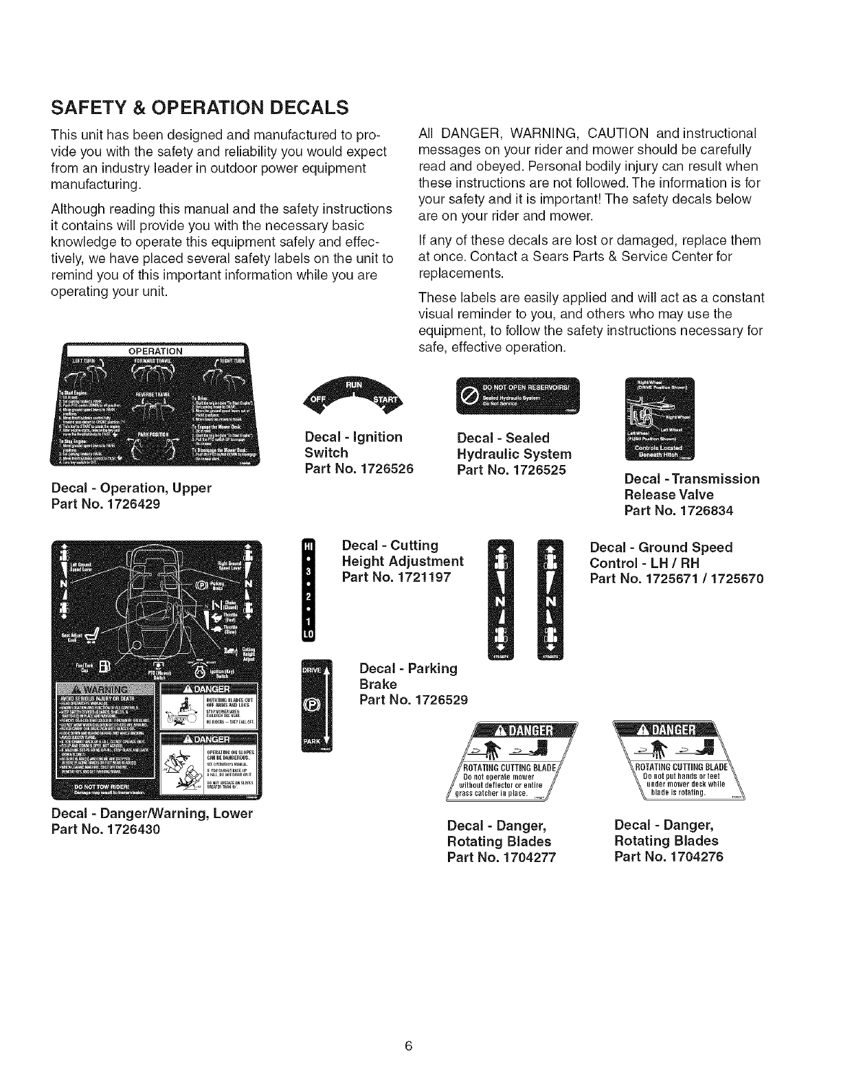
SAFETY &OPERATION DECALS
This unit has been designed and manufactured to pro-
vide you with the safety and reliability you would expect
from an industry leader in outdoor power equipment
manufacturing.
Although reading this manual and the safety instructions
it contains will provide you with the necessary basic
knowledge to operate this equipment safely and effec-
tively, we have placed several safety labels on the unit to
remind you of this important information while you are
operating your unit.
OPERATION
Decal -Operation, Upper
Part No. 1726429
Decal - Danger/Warning, Lower
Part No. 1726430
Decal - Ignition
Switch
Part No. 1726526
All DANGER, WARNING, CAUTION and instructional
messages on your rider and mower should be carefully
read and obeyed. Personal bodily injury can result when
these instructions are not followed. The information is for
your safety and it is important! The safety decals below
are on your rider and mower.
If any of these decals are lost or damaged, replace them
at once. Contact a Sears Parts & Service Center for
replacements.
These labels are easily applied and will act as a constant
visual reminder to you, and others who may use the
equipment, to follow the safety instructions necessary for
safe, effective operation.
Decal - Sealed
Hydraulic System
Part No. 1726525 Decal -Transmission
Release Valve
Part No. 1726834
Decal - Cutting
Height Adjustment
Part No. 1721197
Decal - Ground Speed
Control - LH /RH
Part No. 1725671 /1725670
Decal - Parking
Brake
Part No. 1726529
//ROTATI,GOUTTI.GBLAOE//
/
Decal - Danger,
Rotating Blades
Part No. 1704277
Decal - Danger,
Rotating Blades
Part No. 1704276
IIIlillllllllll
Iliiillililllil
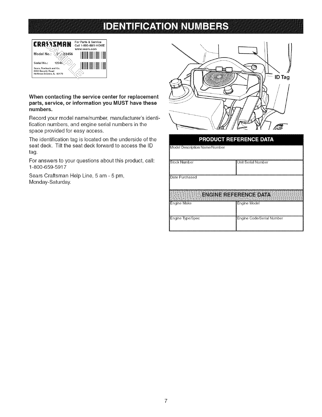
When contacting the service center for replacement
parts, service, or information you MUST have these
numbers.
Record your model name/number, manufacturer's identi-
fication numbers, and engine serial numbers in the
space provided for easy access.
The identification tag is located on the underside of the
seat deck. Tilt the seat deck forward to access the ID
tag.
For answers to your questions about this product, call:
1-800-659-5917
Sears Craftsman Help Line, 5 am - 5 pm,
Monday-Saturday.
\
Model Description Name/Number
Stock Number Unit Serial Number
Date Purchased
Engine Make Engine Model
Engine Type/Spec Engine Code/Serial Number
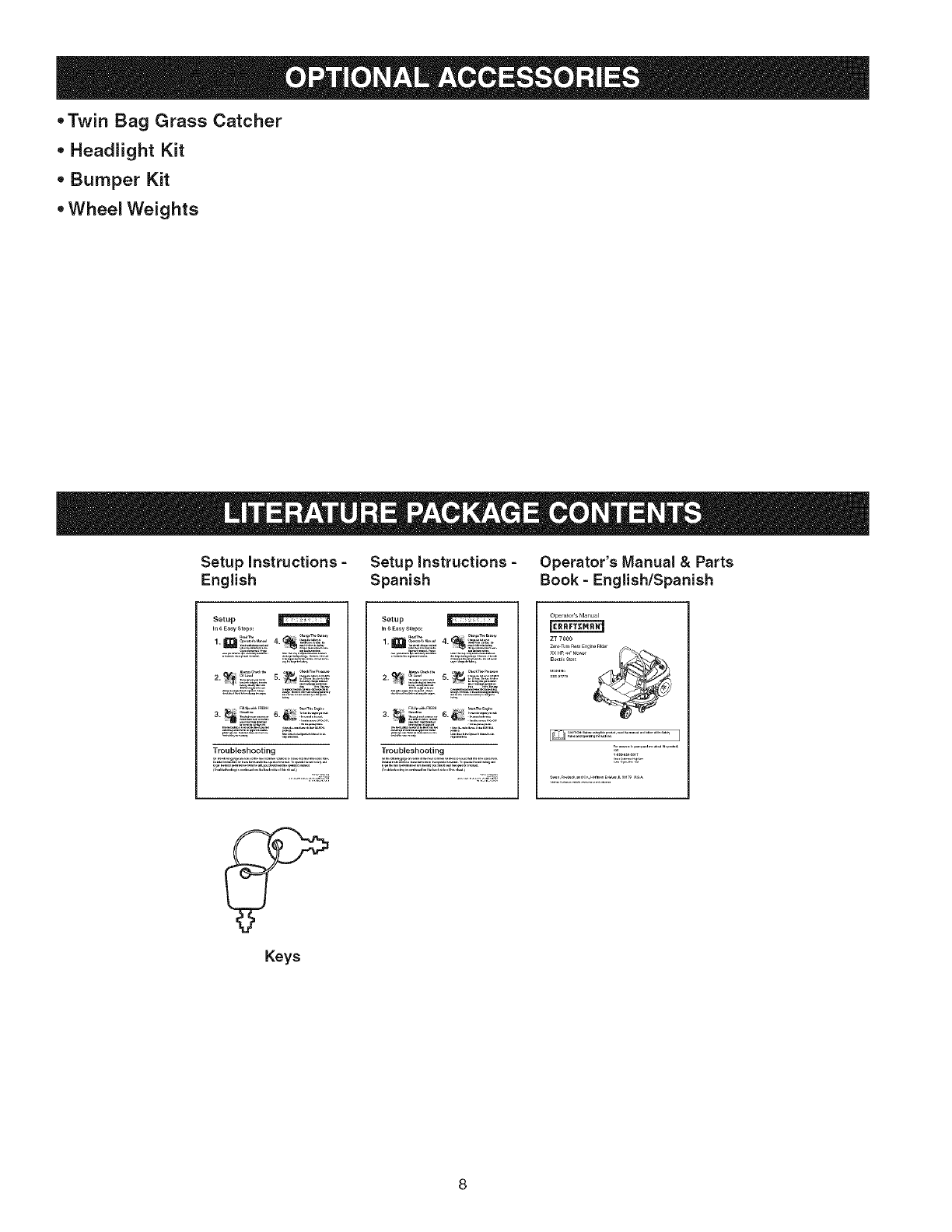
- Twin Bag Grass Catcher
- Headlight Kit
• Bumper Kit
• Wheel Weights
Setup instructions -Setup instructions -Operator's Manual & Parts
English Spanish Book -English/Spanish
Setup
in6 E_y Step:
Troubleshooting
Setup
i_,_ _asv Step_:
......... _,_ ,,=__,
2._ _2:_:_s._ _2_)_u_'
Troubleshooting
Oper_toCsManu_l
Z_ 7OOO
_ri, rt
Keys
m
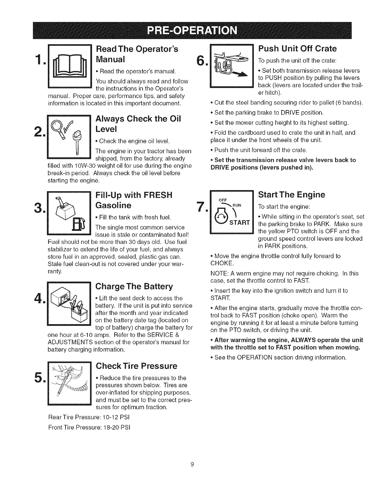
Read The Operator's
Manual
• Read the operator's manual.
You should always read and follow
the instructions in the Operator's
manual. Proper care, performance tips, and safety
information is located in this important document.
1
Always Check the Oil
Level
Check the engine oil level.
The engine in your tractor has been
shipped, from the factory, already
filled with 10W-30 weight oil for use during the engine
break-in period. Always check the oil level before
starting the engine.
m
Push Unit Off Crate
To push the unit off the crate:
Set both transmission release levers
to PUSH position by pulling the levers
back (levers are located under the trail-
er hitch).
Cut the steel banding securing rider to pallet (6 bands).
Set the parking brake to DRIVE position.
Set the mower cutting height to its highest setting.
Fold the cardboard used to crate the unit in half, and
place it under the front wheels of the unit.
Push the unit forward off the crate.
• Set the transmission release valve levers back to
DRIVE positions (levers pushed in).
3m
4m
5m
Fill=Up with FRESH
Gasoline
Fill the tank with fresh fuel.
The single most common service
issue is stale or contaminated fuel!
Fuel should not be more than 30 days old. Use fuel
stabilizer to extend the life of your fuel, and always
store fuel in an approved, sealed, plastic gas can.
Stale fuel clean-out is not covered under your war-
ranty.
one hour at 6-10
Charge The Battery
• Lift the seat deck to access the
battery. If the unit is put into service
after the month and year indicated
on the battery date tag (located on
top of battery) charge the battery for
amps. Refer to the SERVICE &
ADJUSTMENTS section of the operator's manual for
battery charging information.
Check Tire Pressure
Reduce the tire pressures to the
pressures shown below. Tires are
over-inflated for shipping purposes,
and must be set to the correct pres-
sures for optimum traction.
Rear Tire Pressure: 10-12 PSI
m
Start The Engine
OFF
"_, RUN TOstart the engine:
'_ • While sitting in the operator's seat, set
START the parking brake to PARK. Make sure
the yellow PTO switch is OFF and the
ground speed control levers are locked
in PARK positions.
Move the engine throttle control fully forward to
CHOKE.
NOTE: A warm engine may not require choking. In this
case, set the throttle control to FAST.
insert the key into the ignition switch and turn it to
START.
After the engine starts, gradually move the throttle con-
trol back to FAST position (choke open). Warm the
engine by running it for at least a minute before turning
on the PTO switch, or driving the unit.
After warming the engine, ALWAYS operate the unit
with the throttle set to FAST position when mowing.
See the OPERATION section driving information.
Front Tire Pressure: 18-20 PSi
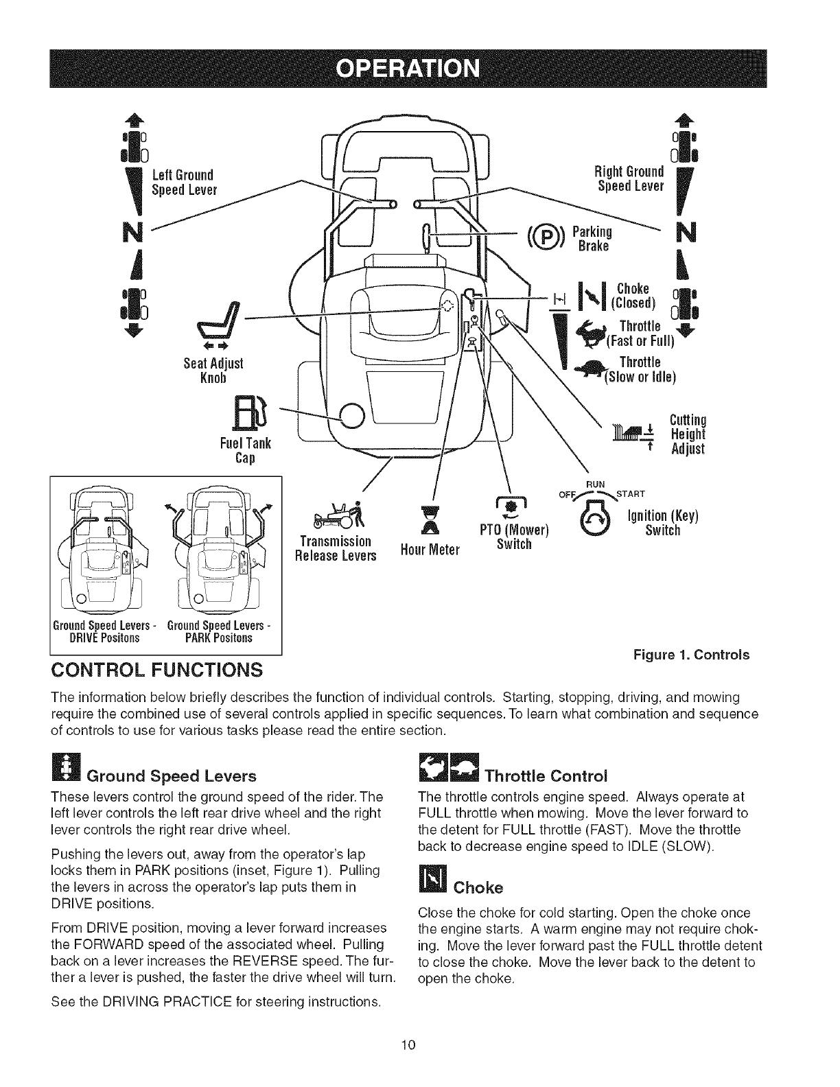
_Left Ground RightGround
SpeedLever SpeedLever
NParking
Brake N
Transmission
ReleaseLevers
GroundSpeedLevers-GroundSpeedLevers-
DRIVEPositons PARKPositons
CONTROL FUNCTIONS Figure 1. Controls
The information below briefly describes the function of individual controls. Starting, stopping, driving, and mowing
require the combined use of several controls applied in specific sequences. To learn what combination and sequence
of controls to use for various tasks please read the entire section.
Ground Speed Levers
These levers control the ground speed of the rider. The
left lever controls the left rear drive wheel and the right
lever controls the right rear drive wheel.
Pushing the levers out, away from the operator's lap
locks them in PARK positions (inset, Figure 1). Pulling
the levers in across the operator's lap puts them in
DRIVE positions.
From DRIVE position, moving a lever forward increases
the FORWARD speed of the associated wheel. Pulling
back on a lever increases the REVERSE speed. The fur-
ther a lever is pushed, the faster the drive wheel will turn.
_Throttle Control
The throttle controls engine speed. Always operate at
FULL throttle when mowing. Move the lever forward to
the detent for FULL throttle (FAST). Move the throttle
back to decrease engine speed to IDLE (SLOW).
Choke
Close the choke for cold starting. Open the choke once
the engine starts. A warm engine may not require chok-
ing. Move the lever forward past the FULL throttle detent
to close the choke. Move the lever back to the detent to
open the choke.
See the DRiViNG PRACTICE for steering instructions.
10
Mower Height of Cut Adjustment
To adjust cutting height, rotate the turn crank clockwise
to raise the mower deck and counterclockwise to lower
the mower deck.
ignition Switch
The ignition switch starts and stops the engine; it has
three positions:
OFF Stops the engine and shuts off the
electrical system.
RUN Allows the engine to run and powers the
electrical system.
START Cranks the engine for starting.
NOTE." Never leave the ignition switch in the RUN posi-
tion with the engine stopped. This drains the battery.
BHour Meter
The hour meter measures the number of hours the key
has been in the RUN position. The hour meter will flash
an oil change indicator at 5 hours, and a lubrication
reminder every 50 hours. These reminders will automati-
cally reset themselves.
NOTE." The hour meter will register the passage of time
when the key is in the RUN position, even if the engine is
not running.
PTO Switch
The PTO (Power Take-Off) switch engages and disen-
gages an electric clutch attached to the engine crank-
shaft. This electric clutch drives and stops the mower
deck. To turn the mower on, pull the switch UP. Push the
switch DOWN to turn the mower off. Note that the opera-
tor must be seated firmly in the rider seat for the PTO to
function.
Transmission Release Levers
The transmission release levers deactivate the transmis-
sions so that the unit can be pushed by hand. See
PUSHING THE UNIT BY HAND for operational informa-
tion.
Seat Adjustment Knob
The seat can be adjusted forward and backward. Tip the
seat forward, loosen the adjustment knob, slide the seat
to the desired position, and tighten the knob.
Fuel Tank
To remove the cap, turn counterclockwise.
Parking Brake
DRIVE Releases the parking brake.
PARK Locks the parking brake.
Pull the parking brake lever up to engage the parking
brake (PARK position). Move the lever fully down to dis-
engage the parking brake (DRIVE position).
NOTE: To start the unit the parking brake must be in
PARK position.
GENERAL OPERATING SAFETY
Before first time operation:
• Be sure to read all information in the Safety and
Operation sections before attempting to operate this
rider and mower.
• Become familiar with all of the controls and how to stop
the unit.
• Drive in an open area without mowing to become accus-
tomed to driving the unit.
,WARNING
If you do not understand how a specific control
functions, or have not yet thoroughly read the
CONTROL FUNCTIONS section, do so now.
Do NOT attempt to operate the rider without first
becoming familiar with the location and function
of ALL controls.
11
CHECKS BEFORE STARTING
• Check that the crankcase oil is filled to full mark on
dipstick.
• Adjust the seat position and make certain you can
reach all controls.
Fill the fuel tank with fresh fuel.
FUEL RECOMMENDATIONS
For daily operation: Use only unleaded gasoline with a
pump sticker octane rating of 87 or higher. Gasohol (up
to 10% ethyl alcohol, 90% unleaded gasoline by volume)
is approved as a fuel. Methyl Teriary Butyl Ether (MTBE)
and unleaded gasoline blends (up to a maximum of 15%
MTBE by volume) are approved as a fuel. No other gaso-
line/alcohol or gasoline/ether blends are approved. Do
not use fuel additives other than fuel stabilizer.
For storage: CAUTION: Alcohol blended fuels (called
gasohol or using ethanol or methanol) can attract mois-
ture which leads to separation and formation of acids
during storage. Acidic gas can damage the fuel system
of an engine while in storage.
To avoid engine problems, the fuel system should be
emptied before storage of 30 days or longer. Drain the
gas tank, start the engine, and let it run until the fuel
lines and carburetor are empty (see STORAGE for fuel
draining procedure). Use fresh fuel next season. See
STORAGE instructions for additional information.
Never use engine or carburetor cleaner products in the
fuel tank or permanent damage may occur. To add fuel:
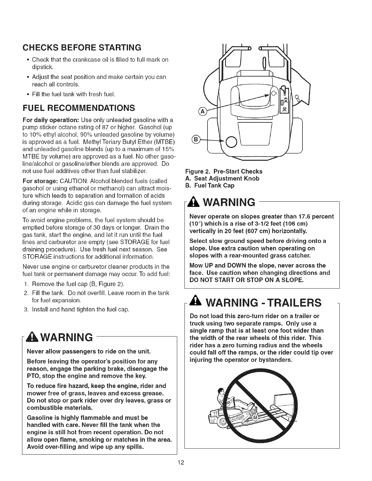
1. Remove the fuel cap (B, Figure 2).
2. Fill the tank. Do not overfill. Leave room in the tank
for fuel expansion.
3. Install and hand tighten the fuel cap.
tLWARNING
Never allow passengers to ride on the unit.
Before leaving the operator's position for any
reason, engage the parking brake, disengage the
PTO, stop the engine and remove the key.
To reduce fire hazard, keep the engine, rider and
mower free of grass, leaves and excess grease.
Do not stop or park rider over dry leaves, grass or
combustible materials.
Gasoline is highly flammable and must be
handled with care. Never fill the tank when the
engine is still hot from recent operation. Do not
allow open flame, smoking or matches in the area.
Avoid over=filling and wipe up any spills.
Figure 2. Pre=Start Checks
A. Seat Adjustment Knob
B. Fuel Tank Cap
WARNING
Never operate on slopes greater than 17.6 percent
(10 °) which is arise of 3=1/2 feet (106 cm)
vertically in 20 feet (607 cm) horizontally.
Select slow ground speed before driving onto a
slope. Use extra caution when operating on
slopes with a rear=mounted grass catcher.
Mow UP and DOWN the slope, never across the
face. Use caution when changing directions and
DO NOT START OR STOP ON A SLOPE.
WARNING - TRAILERS
Do not load this zero-turn rider on a trailer or
truck using two separate ramps. Only use a
single ramp that is at least one foot wider than
the width of the rear wheels of this rider. This
rider has a zero turning radius and the wheels
could fall off the ramps, or the rider could tip over
injuring the operator or bystanders.
12
EMERGENCY STOPPING
In the event of an emergency the engine can be stopped
by simply turning the ignition switch to STOR Use this
method only in emergency situations. For normal engine
shut down follow the procedure given in STOPPING THE
RIDER AND ENGINE.
STOPPING THE RIDER & ENGINE
1. Returning the ground speed control levers to PARK
positions will stop rider movement.
2. Stop the mower by pushing down on the PTO switch.
3. Move the parking brake lever to PARK position.
4. Move the throttle control to FAST position and turn
the ignition key to OFR Remove the key.
STARTING THE ENGINE
1. While sitting in the operator's seat, set the parking
brake to PARK. Make sure the PTO switch is OFF
and the ground speed control levers are locked in
PARK positions.
2. Move the engine throttle control fully forward to
CHOKE.
NOTE: A warm engine may not require choking. In this
case, set the throttle control to FAST
3. Insert the key into the ignition switch and turn it to
START.
4. After the engine starts, gradually move the throttle
control back to FAST position (choke open). Warm
the engine by running it for at least a minute before
turning on the PTO switch, or driving the unit.
5. After warming the engine, ALWAYS operate the
unit with the throttle set to FAST position when
mowing.
MOWING
1. Place the parking brake lever in PARK position. Make
sure the PTO switch is OFF, the ground speed control
levers are locked in their PARK positions, and the
operator is in the seat.
2. Set the mower cutting height to the desired setting.
3. Start the engine (see STARTING THE ENGINE).
4. Set the throttle to FAST.
5. Turn the PTO switch ON to engage the mower deck.
6. Move the parking brake lever to DRIVE position.
7. Move the ground speed control levers from PARK
positions to drive positions (levers in across the oper-
ator's lap).
8. Begin mowing. See DRIVING PRACTICE.
9. When finished, turn the PTO switch OFR
10. Stop the engine (see STOPPING THE RIDER AND
ENGINE).
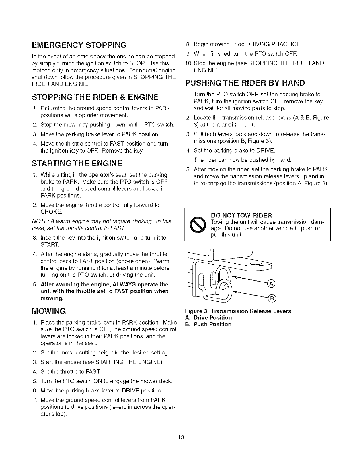
PUSHING THE RIDER BY HAND
1. Turn the PTO switch OFF, set the parking brake to
PARK, turn the ignition switch OFF, remove the key,
and wait for all moving parts to stop.
2. Locate the transmission release levers (A & B, Figure
3) at the rear of the unit.
3. Pull both levers back and down to release the trans-
missions (position B, Figure 3).
4. Set the parking brake to DRIVE.
The rider can now be pushed by hand.
5. After moving the rider, set the parking brake to PARK
and move the transmission release levers up and in
to re-engage the transmissions (position A, Figure 3).
DO NOTTOW RIDER
Towing the unit will cause transmission dam-
age. Do not use another vehicle to push or
pull this unit.
Figure 3. Transmission Release Levers
A. Drive Position
B. Push Position
13
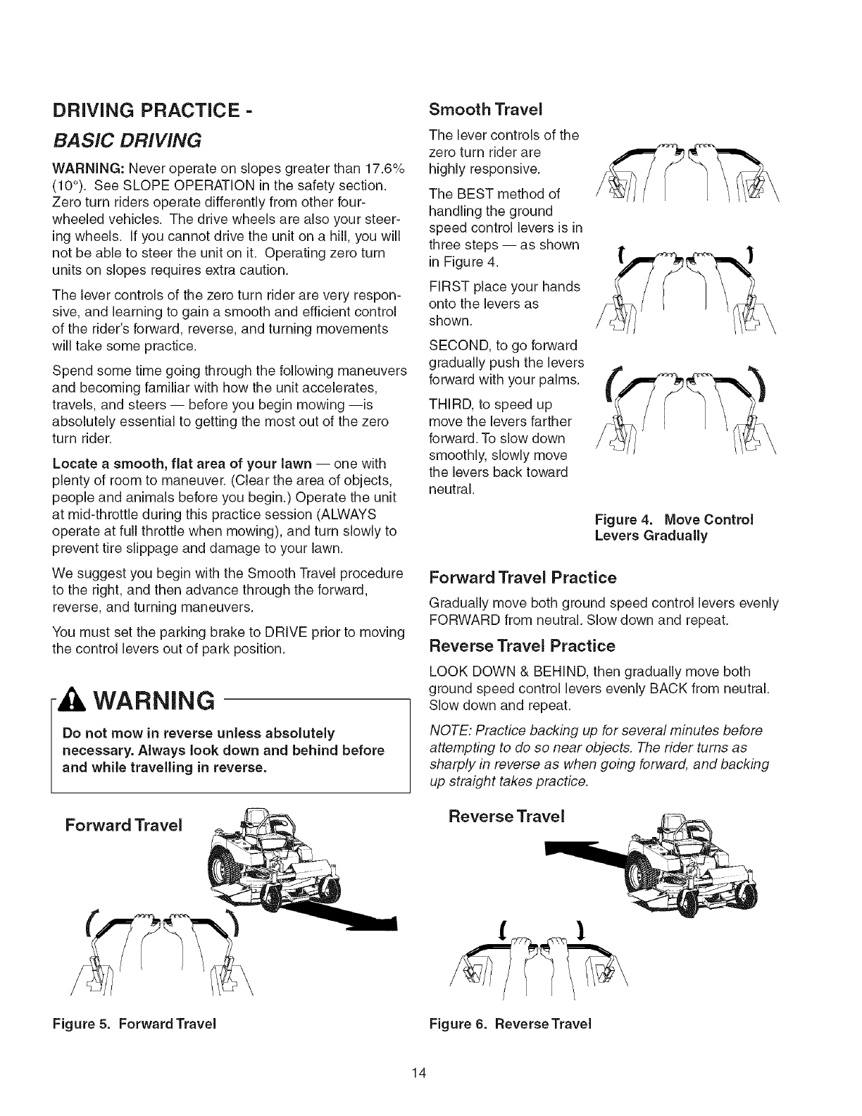
DRiViNG PRACTICE-
BASIC DRIVING
WARNING: Never operate on slopes greater than 17.6%
(10°). See SLOPE OPERATION in the safety section.
Zero turn riders operate differently from other bur-
wheeled vehicles. The drive wheels are also your steer-
ing wheels. If you cannot drive the unit on a hill, you will
not be able to steer the unit on it. Operating zero turn
units on slopes requires extra caution.
The lever controls of the zero turn rider are very respon-
sive, and learning to gain a smooth and efficient control
of the rider's forward, reverse, and turning movements
will take some practice.
Spend some time going through the following maneuvers
and becoming familiar with how the unit accelerates,
travels, and steers -- before you begin mowing --is
absolutely essential to getting the most out of the zero
turn rider.
Locate a smooth, fiat area of your lawn -- one with
plenty of room to maneuver. (Clear the area of objects,
people and animals before you begin.) Operate the unit
at mid-throttle during this practice session (ALWAYS
operate at full throttle when mowing), and turn slowly to
prevent tire slippage and damage to your lawn.
We suggest you begin with the Smooth Travel procedure
to the right, and then advance through the forward,
reverse, and turning maneuvers.
You must set the parking brake to DRIVE prior to moving
the control levers out of park position.
WARNING
Do not mow in reverse unless absolutely
necessary. Always look down and behind before
and while travelling in reverse.
Forward Travel
Smooth Travel
The lever controls of the
zero turn rider are
highly responsive.
The BEST method of
handling the ground
speed control levers is in
three steps -- as shown
in Figure 4.
FIRST place your hands
onto the levers as
shown.
SECOND, to go forward
gradually push the levers
forward with your palms.
THIRD, to speed up
move the levers farther
forward. To slow down
smoothly, slowly move
the levers back toward
neutral.
Figure 4. Move Control
Levers Gradually
Forward Travel Practice
Gradually move both ground speed control levers evenly
FORWARD from neutral. Slow down and repeat.
Reverse Travel Practice
LOOK DOWN & BEHIND, then gradually move both
ground speed control levers evenly BACK from neutral.
Slow down and repeat.
NOTE: Practice backing up for several minutes before
attempting to do so near objects. The rider turns as
sharply in reverse as when going forward, and backing
up straight takes practice.
Reverse Travel
Figure 5. Forward Travel Figure 6. Reverse Travel
14
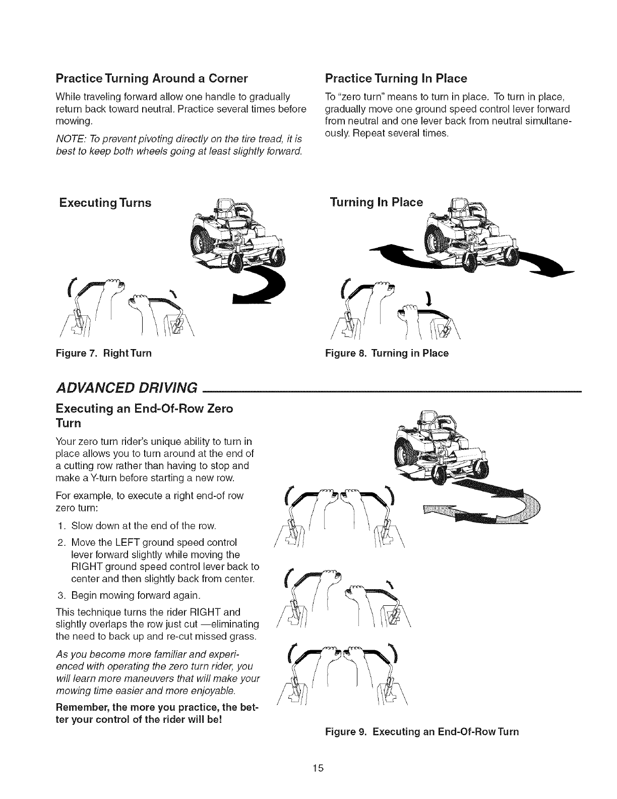
Practice Turning Around aCorner
While traveling forward allow one handle to gradually
return back toward neutral. Practice several times before
mowing.
NOTE." To prevent piveting directly on the tire tread, it is
best to keep both wheels going at least slightly forward.
Practice Turning in Place
To "zero turn" means to turn in place. To turn in place,
gradually move one ground speed control lever forward
from neutral and one lever back from neutral simultane-
ously. Repeat several times.
Executing Turns Turning In Place
Figure 7. RightTurn Figure 8. Turning in Place
ADVANCED DRIVING
Executing an End=Of=Row Zero
Turn
Your zero turn rider's unique ability to turn in
place allows you to turn around at the end of
a cutting row rather than having to stop and
make a Y-turn before starting a new row.
For example, to execute a right end-of row
zero turn:
1. Slow down at the end of the row.
2. Move the LEFT ground speed control
lever forward slightly while moving the
RIGHT ground speed control lever back to
center and then slightly back from center.
3. Begin mowing forward again.
This technique turns the rider RIGHT and
slightly overlaps the row just cut --eliminating
the need to back up and re-cut missed grass.
As you become more familiar and experi-
enced with operating the zero turn rider, you
will learn more maneuvers that will make your
mowing time easier and more enjoyable.
Remember, the more you practice, the bet=
ter your control of the rider will be!
Figure 9. Executing an End-Of-RowTurn
15
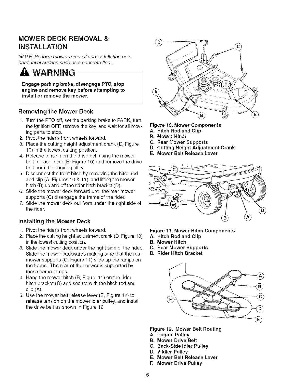
MOWER DECK REMOVAL &
INSTALLATION
NOTE: Perform mower removal and installation on a
hard, level surface such as a concrete floor.
WARNING
Engage parking brake, disengage PTO, stop
engine and remove key before attempting to
install or remove the mower.
Removing the Mower Deck
1. Turn the PTO off, set the parking brake to PARK, turn
the ignition OFF, remove the key, and wait for all mov-
ing parts to stop.
2. Pivot the rider's front wheels forward.
3. Place the cutting height adjustment crank (D, Figure
10) in the lowest cutting position.
4. Release tension on the drive belt using the mower
belt release lever (E, Figure 10) and remove the drive
belt from the engine pulley.
5. Disconnect the front hitch by removing the hitch rod
and clip (A, Figures 10 & 11), and lifting the mower
hitch (B) up and off the rider hitch bracket (D).
6. Slide the mower deck forward until the rear mower
supports (C) disengage the frame of the rider.
7. Slide the mower deck out from under the right side of
the rider.
Installing the Mower Deck
1. Pivot the rider's front wheels forward.
2. Place the cutting height adjustment crank (D, Figure 10)
in the lowest cutting position.
3. Slide the mower deck under the right side of the rider.
Slide the mower backwards making sure that the rear
mower supports (C, Figure 11) slide up the ramps on
the frame. The rear of the mower is supported by
these frame ramps.
4. Hang the mower hitch (B, Figure 11) on the rider
hitch bracket (D) and secure with the hitch rod and
clip (A).
5. Use the mower belt release lever (E, Figure 12) to
release tension on the mower idler pulley, and install
the drive belt as shown in Figure 12.
Figure 10. Mower Components
A. Hitch Rod and Clip
B. Mower Hitch
C. Rear Mower Supports
D. Cutting Height Adjustment Crank
E. Mower Belt Release Lever
Figure 11. Mower Hitch Components
A. Hitch Rod and Clip
B. Mower Hitch
C. Rear Mower Supports
D. Rider Hitch Bracket
Figure 12. Mower Belt Routing
A. Engine Pulley
B. Mower Drive Belt
C. Back=Side Idler Pulley
D. V=ldler Pulley
E. Mower Belt Release Lever
F. Mower Drive Pulley
16
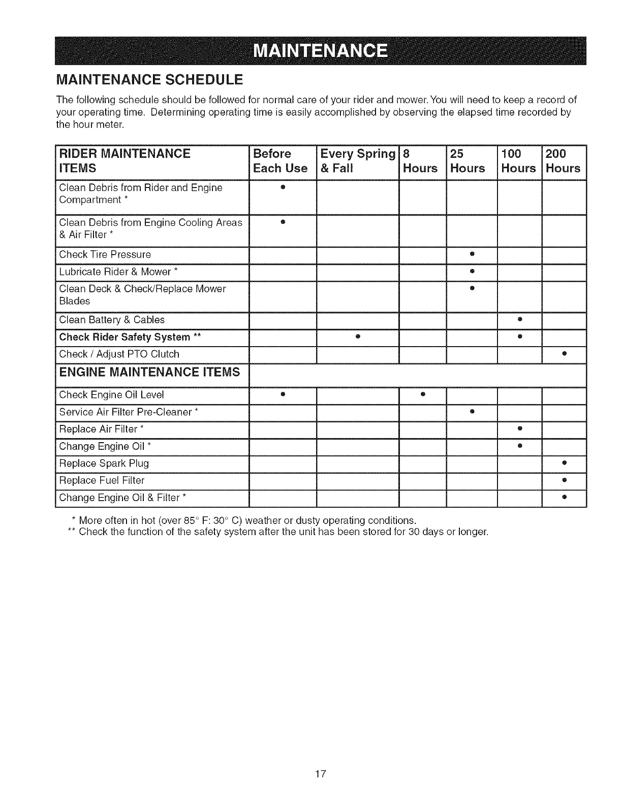
MAINTENANCE SCHEDULE
The following schedule should be followed for normal care of your rider and mower. You will need to keep a record of
your operating time. Determining operating time is easily accomplished by observing the elapsed time recorded by
the hour meter.
RIDER MAINTENANCE Before Every Spring 8 25 100 200
ITEMS Each Use &Fall Hours Hours Hours Hours
Clean Debris from Rider and Engine =
Compartment *
Clean Debris from Engine Cooling Areas ®
& Air Filter *
Check Tire Pressure •
Lubricate Rider & Mower * ®
Clean Deck & Check/Replace Mower •
Blades
Clean Battery & Cables ®
Check Rider Safety System ** • •
Check /Adjust PTO Clutch •
ENGINE MAINTENANCE ITEMS
Check Engine Oil Level • •
Service Air Filter Pre-Cleaner * ®
Replace Air Filter *
Change Engine Oil *
Replace Spark Plug
Replace Fuel Filter
Change Engine Oil & Filter *
• More often in hot (over 85 ° F: 30 ° C) weather or dusty operating conditions.
•* Check the function of the safety system after the unit has been stored for 30 days or longer.
o
®
®
o
®
17
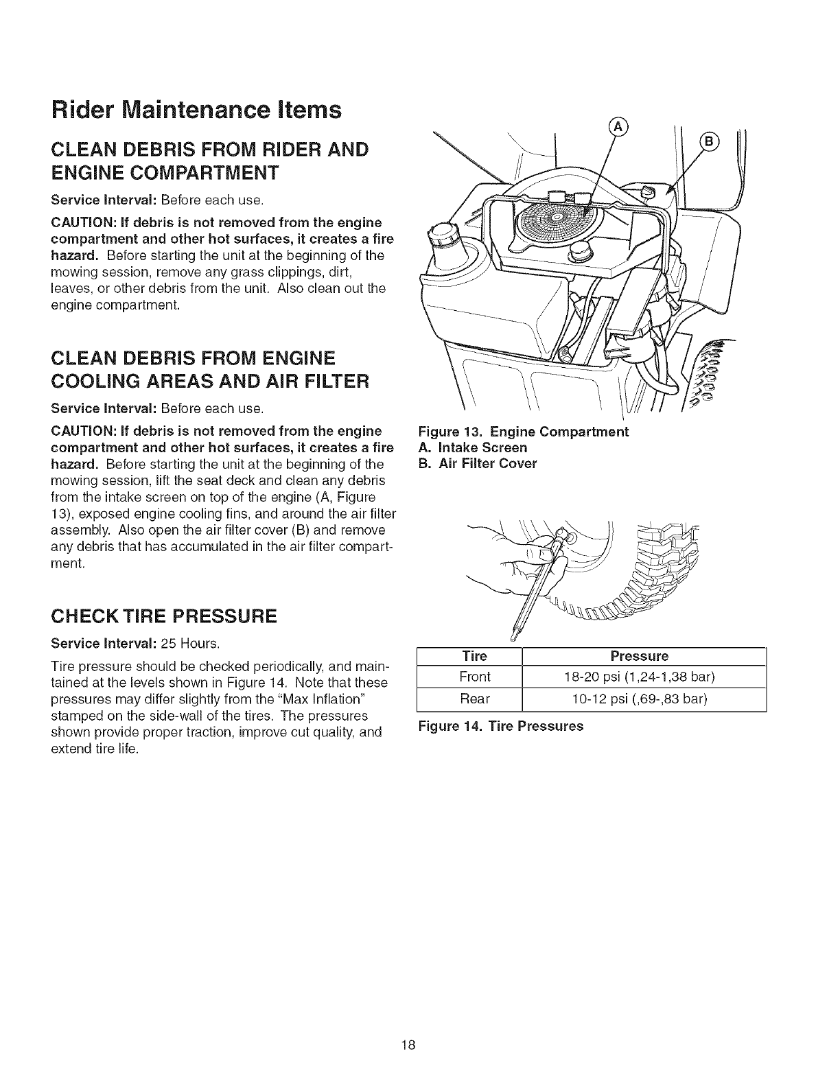
Rider Maintenance items
CLEAN DEBRIS FROM RIDER AND
ENGINE COMPARTMENT
Service IntervaJ: Before each use.
CAUTION: if debris is not removed from the engine
compartment and other hot surfaces, it creates a fire
hazard. Before starting the unit at the beginning of the
mowing session, remove any grass clippings, dirt,
leaves, or other debris from the unit. Also clean out the
engine compartment.
CLEAN DEBRIS FROM ENGINE
COOLING AREAS AND AIR FILTER
Service Interval: Before each use.
CAUTION: if debris is not removed from the engine
compartment and other hot surfaces, it creates a fire
hazard. Before starting the unit at the beginning of the
mowing session, lift the seat deck and clean any debris
from the intake screen on top of the engine (A, Figure
13), exposed engine cooling fins, and around the air filter
assembly. Also open the air filter cover (B) and remove
any debris that has accumulated in the air filter compart-
ment.
CHECKTIRE PRESSURE
Service Interval: 25 Hours.
Tire pressure should be checked periodically, and main-
tained at the levels shown in Figure 14. Note that these
pressures may differ slightly from the "Max Inflation"
stamped on the side-wall of the tires. The pressures
shown provide proper traction, improve cut quality, and
extend tire life.
Figure 13. Engine Compartment
A. intake Screen
B. Air Filter Cover
Tire Pressure
Front 18-20 psi (1,24-1,38 bar)
Rear 10-12 psi (,69-,83 bar)
Figure 14. Tire Pressures
18
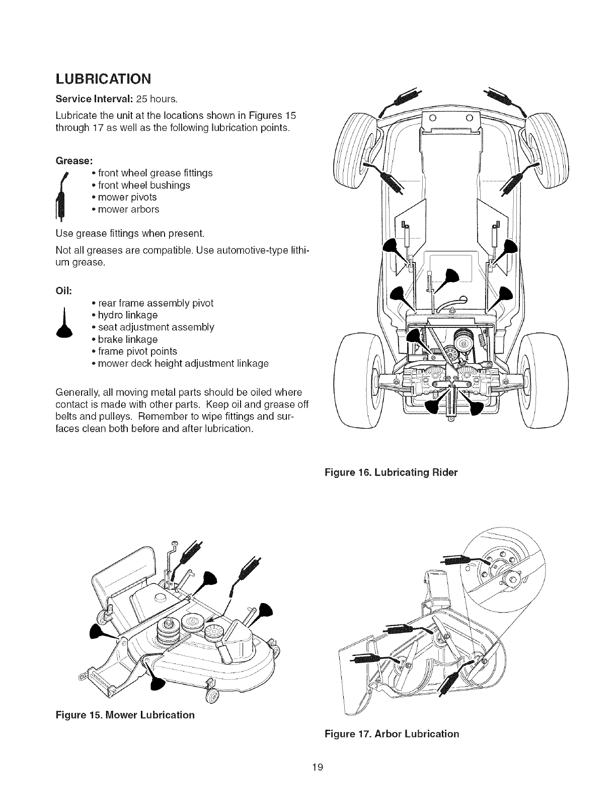
LUBRiCATiON
Service Interval: 25 hours.
Lubricate the unit at the locations shown in Figures 15
through 17 as well as the following lubrication points.
Grease:
r_ . front wheel grease fittings
• front wheel bushings
• mower pivots
• mower arbors
Use grease fittings when present.
Not all greases are compatible. Use automotive-type lithi-
um grease.
Oil:
,L rear frame assembly pivot
•hydro linkage
•seat adjustment assembly
• brake linkage
frame pivot points
• mower deck height adjustment linkage
Generally, all moving metal parts should be oiled where
contact is made with other parts. Keep oil and grease off
belts and pulleys. Remember to wipe fittings and sur-
faces clean both before and after lubrication.
Figure 16. Lubricating Rider
/
Figure 15. Mower Lubrication
Figure 17. Arbor Lubrication
19
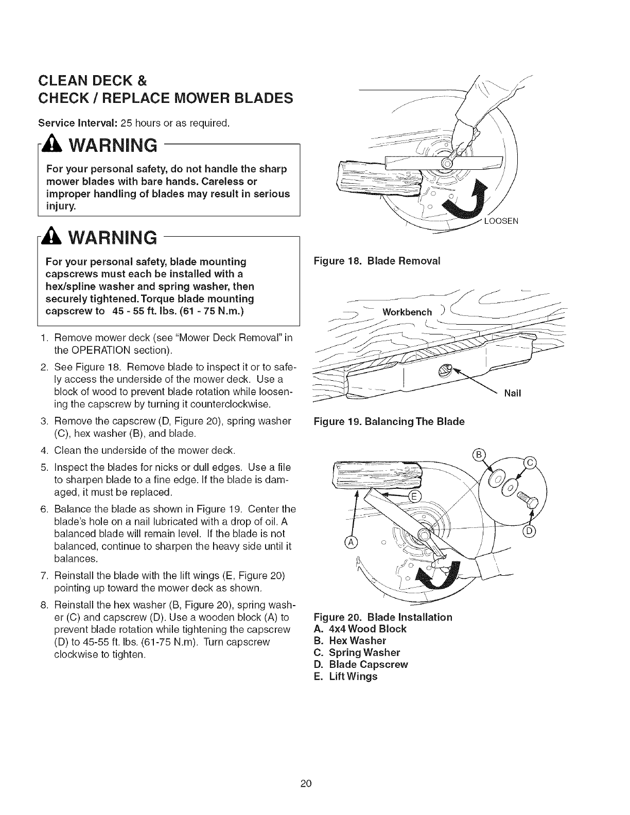
CLEAN DECK &
CHECK /REPLACE MOWER BLADES
Service Intervah 25 hours or as required.
WARNING
For your personal safety, do not handle the sharp
mower blades with bare hands. Careless or
improper handling of blades may result in serious
injury.
WARNING
For your personal safety, blade mounting
capscrews must each be installed with a
hex/spline washer and spring washer, then
securely tightened. Torque blade mounting
capscrew to 45 -55 ft. Ibs. (61 -75 N.m.)
1. Remove mower deck (see "Mower Deck Removal" in
the OPERATION section).
2. See Figure 18. Remove blade to inspect it or to safe-
ly access the underside of the mower deck. Use a
block of wood to prevent blade rotation while loosen-
ing the capscrew by turning it counterclockwise.
3. Remove the capscrew (D, Figure 20), spring washer
(C), hex washer (B), and blade.
4. Clean the underside of the mower deck.
5. Inspect the blades for nicks or dull edges. Use a file
to sharpen blade to a fine edge. If the blade is dam-
aged, it must be replaced.
6. Balance the blade as shown in Figure 19. Center the
blade's hole on a nail lubricated with a drop of oil. A
balanced blade will remain level. If the blade is not
balanced, continue to sharpen the heavy side until it
balances.
7. Reinstall the blade with the lift wings (E, Figure 20)
pointing up toward the mower deck as shown.
8. Reinstall the hex washer (B, Figure 20), spring wash-
er (C) and capscrew (D). Use a wooden block (A) to
prevent blade rotation while tightening the capscrew
(D) to 45-55 ft. Ibs. (61-75 N.m). Turn capscrew
clockwise to tighten.
Figure 18. Blade Removal
Workbench
Figure 19. Balancing The Blade
Figure 20. Blade installation
A. 4x4 Wood Block
B. Hex Washer
C. Spring Washer
D. Blade Capscrew
E. Lift Wings
J
J
LOOSEN
Nail
2O
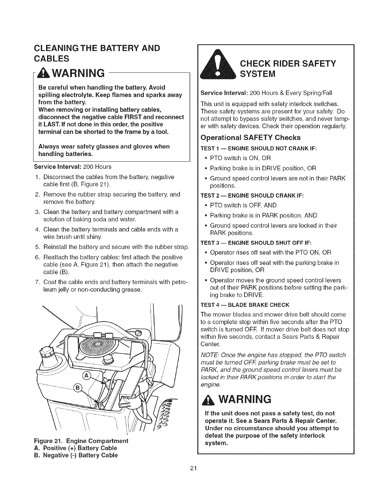
CLEANING THE BATTERY AND
CABLES
WARNING
Be careful when handling the battery. Avoid
spilling electrolyte. Keep flames and sparks away
from the battery.
When removing or installing battery cables,
disconnect the negative cable FIRST and reconnect
it LAST. if not done in this order, the positive
terminal can be shorted to the frame by a tool.
Always wear safety glasses and gloves when
handling batteries.
Service interval: 200 Hours
1. Disconnect the cables from the battery, negative
cable first (B, Figure 21).
2. Remove the rubber strap securing the battery, and
remove the battery.
3. Clean the battery and battery compartment with a
solution of baking soda and water.
4. Clean the battery terminals and cable ends with a
wire brush until shiny.
5. Reinstall the battery and secure with the rubber strap.
6. Reattach the battery cables: first attach the positive
cable (see A, Figure 21), then attach the negative
cable (B).
7. Coat the cable ends and battery terminals with petro-
leum jelly or non-conducting grease.
Figure 21. Engine Compartment
A. Positive (+) Battery Cable
B. Negative (=) Battery Cable
CHECK RIDER SAFETY
SYSTEM
Service Interval: 200 Hours & Every Spring/Fall
This unit is equipped with safety interlock switches.
These safety systems are present for your safety. Do
not attempt to bypass safety switches, and never tamp-
er with safety devices. Check their operation regularly.
Operational SAFETY Checks
TEST 1 -- ENGINE SHOULD NOT CRANK IF:
• PTO switch is ON, OR
Parking brake is in DRIVE position, OR
Ground speed control levers are not in their PARK
positions.
TEST 2 -- ENGINE SHOULD CRANK IF:
• PTO switch is OFF, AND
Parking brake is in PARK position, AND
Ground speed control levers are locked in their
PARK positions.
TEST 3-- ENGINE SHOULD SHUT OFF IF:
• Operator rises off seat with the PTO ON, OR
• Operator rises off seat with the parking brake in
DRIVE position, OR
• Operator moves the ground speed control levers
out of their PARK positions before setting the park-
ing brake to DRIVE.
TEST 4 -- BLADE BRAKE CHECK
The mower blades and mower drive belt should come
to a complete stop within five seconds after the PTO
switch is turned OFE If mower drive belt does not stop
within five seconds, contact a Sears Parts & Repair
Center.
NOTE: Once the engine has stopped, the PTO switch
must be turned OFF, parking brake must be set to
PARK, and the ground speed control levers must be
locked in their PARK positions in order to start the
engine.
WARNING
if the unit does not pass a safety test, do not
operate it. See a Sears Parts & Repair Center.
Under no circumstance should you attempt to
defeat the purpose of the safety interlock
system.
21
CHECK /ADJUST PTO CLUTCH
• ILWARNING
To avoid serious injury, perform adjustments only
with engine stopped, key removed and tractor on
level ground.
Service interval: 200 Hours.
The PTO clutch is engaged and disengaged by the PTO
switch. The clutch powers and brakes the mower blades.
Check the PTO clutch adjustment every 200 hours of
operation. Also perform the following procedure if the
clutch is slipping, will not engage, or if a new clutch has
been installed.
1. Remove key from ignition switch and disconnect
spark plug wires to prevent the possibility of acciden-
tal starting while the PTO is being adjusted.
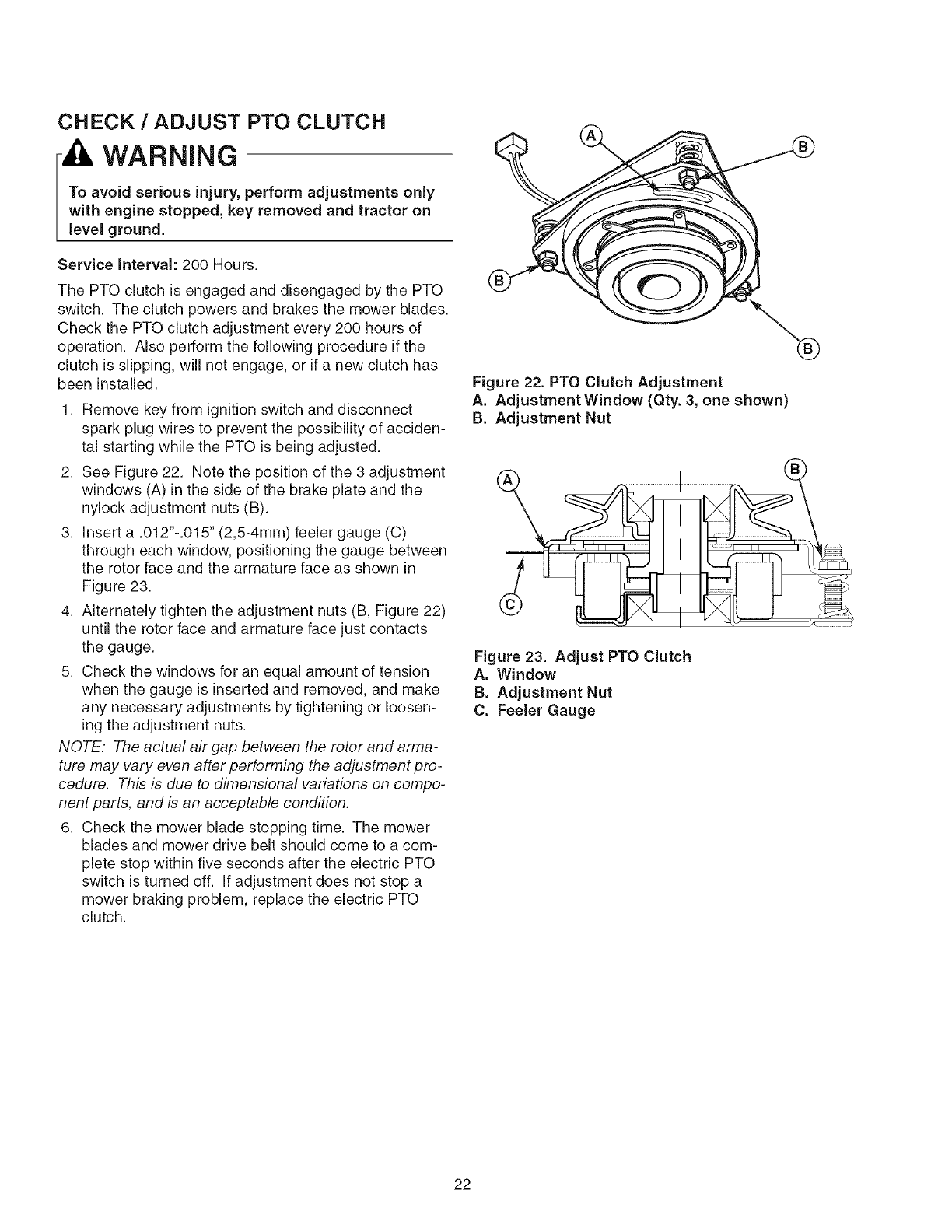
2. See Figure 22. Note the position of the 3 adjustment
windows (A) in the side of the brake plate and the
nylock adjustment nuts (B).
3. Insert a .012"-.015" (2,5-4mm) feeler gauge (C)
through each window, positioning the gauge between
the rotor face and the armature face as shown in
Figure 23.
4. Alternately tighten the adjustment nuts (B, Figure 22)
until the rotor face and armature face just contacts
the gauge.
5. Check the windows for an equal amount of tension
when the gauge is inserted and removed, and make
any necessary adjustments by tightening or loosen-
ing the adjustment nuts.
NOTE: The actual air gap between the rotor and arma-
ture may vary even after performing the adjustment pro-
cedure. This is due to dimensional variations on compo-
nent parts, and is an acceptable condition.
6. Check the mower blade stopping time. The mower
blades and mower drive belt should come to a com-
plete stop within five seconds after the electric PTO
switch is turned off. If adjustment does not stop a
mower braking problem, replace the electric PTO
clutch.
Figure 22. PTO Clutch Adjustment
A. Adjustment Window (Qty. 3, one shown)
B. Adjustment Nut
Figure 23. Adjust PTO Clutch
A. Window
B. Adjustment Nut
C. Feeler Gauge
22
Engine Maintenance items
CHECK ENGINE OIL LEVEL
Service Interval: Before each use, and every 8 hours.
1. Turn the engine off, and set the parking brake to
PARK.
2. Clean the area around the dip stick (C, Figure 25).
Remove the dip stick (C) and clean it with a paper
towel.
3.
4.
5.
Insert the dip stick back into the engine, but do not
thread the cap back onto the tube (D).
Remove the dip stick and read the oil level. The oil
level should be between the "F" and "L" marks (D). If
not, add oil according to the oil recommendations
chart (Figure 24).
CHANGE ENGINE OIL
Service Interval: 100 Hours.
Oil Capacity: .95 Quarts with oil filter change.
Note: Change engine oil while the engine is warm. Run
the engine for a few minutes, then shut the engine off
and allow it to cool from hot to warm.
1. Clean the area around the dip stick (C, Figure 25)
and oil drain tube (A).
2. Remove the oil drain plug (A) from the end of the oil
drain tube. Remove the dip stick (C). Allow ample
time for complete drainage.
3. Reinstall the oil drain plug (A).
4. Fill the crankcase with oil. See CHECK ENGINE OIL
LEVEL above.
CHANGE ENGINE OIL & FILTER
Service Interval: 200 Hours.
Oil Capacity: .95 Quarts with oil filter change.
Note: Change engine oil while the engine is warm. Run
the engine for a few minutes, then shut the engine off
and allow it to cool from hot to warm.
1. Clean the area around the dip stick (C, Figure 25)
and oil drain (A).
2. Remove the oil drain plug (A) and and dip stick (C).
Allow ample time for complete drainage.
3. Remove the oil filter (B). Discard the filter.
4. Turn the new filter upside down and fill with fresh
engine oil. Allow the oil to seep into the new filter for
two minutes.
5. Using a drop of oil on your finger tip, wet the rubber
gasket on the bottom of the new filter.
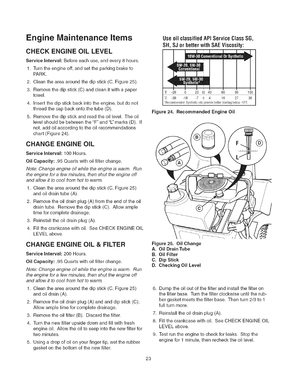
Useoil classifiedAPIService Class SG,
SH, SJ or betterwith SAEViscosity:
i _, , /u
°F -20 0 20 3_2 40 60 80 100
°C -30 -18 -7 O 4 16 27 38
*Recommended: Syntbatic oils provide better starting below -10°E
Figure 24. Recommended Engine Oil
Figure 25. Oil Change
A. Oil Drain Tube
B. Oil Filter
C. Dip Stick
D. Checking Oil Level
6. Dump the oil out of the filter and install the filter on
the filter base. Turn the filter clockwise until the rub-
ber gasket meets the filter base. Then turn 2/3 to 1
full turn more.
7. Reinstall the oil drain plug (A).
8. Fill the crankcase with oil. See CHECK ENGINE OIL
LEVEL above.
9. Test run the engine to check for leaks. Stop the
engine for 1 minute, then recheck the oil level.
23
SERVICE AiR FILTER PRE-CLEANER
Service Interval: 25 Hours or as required.
1. Loosen the air filter cover knob and remove the cover
(A, Figure 26). Clean out any debris from around the
air filter. Inspect the condition of the sealing surfaces
of the air filter element (D) and filter base. Replace
any damaged parts.
2. Remove the foam pre-cleaner (B) from the air filter
element (D).
3. Wash the pre-cleaner (B) with warm water and deter-
gent. Rinse thoroughly. Squeeze out all excess
water. DO NOT wring out. Allow the pre-cleaner to air
dry.
4. Saturate the pre-cleaner with new engine oil.
Squeeze out the excess oil. DO NOT wring out.
Squeeze the pre-cleaner in a paper towel until all
excess oil has been removed.
5. Reinstall the pre-cleaner (B) over the air filter (D).
6. Reinstall the air cleaner cover (A).
REPLACE AIR FILTER
Service interval: 100 Hours or as required.
1. Loosen the air filter cover knob and remove the cover
(A, Figure 26). Clean out any debris from around the
air filter. Inspect the condition of the sealing surfaces
of the air filter (D) and filter base. Replace any dam-
aged parts.
2. Remove the foam pre-cleaner (B) from the air filter
element. Service the pre-cleaner as described in
SERVICE AIR FILTER PRE-CLEANER above.
3. Remove the wing nut (C). Remove and replace the
air filter (D).
4. Reinstall the wingnut (C) and pre-cleaner (B).
5. Reinstall the air cleaner cover (A).
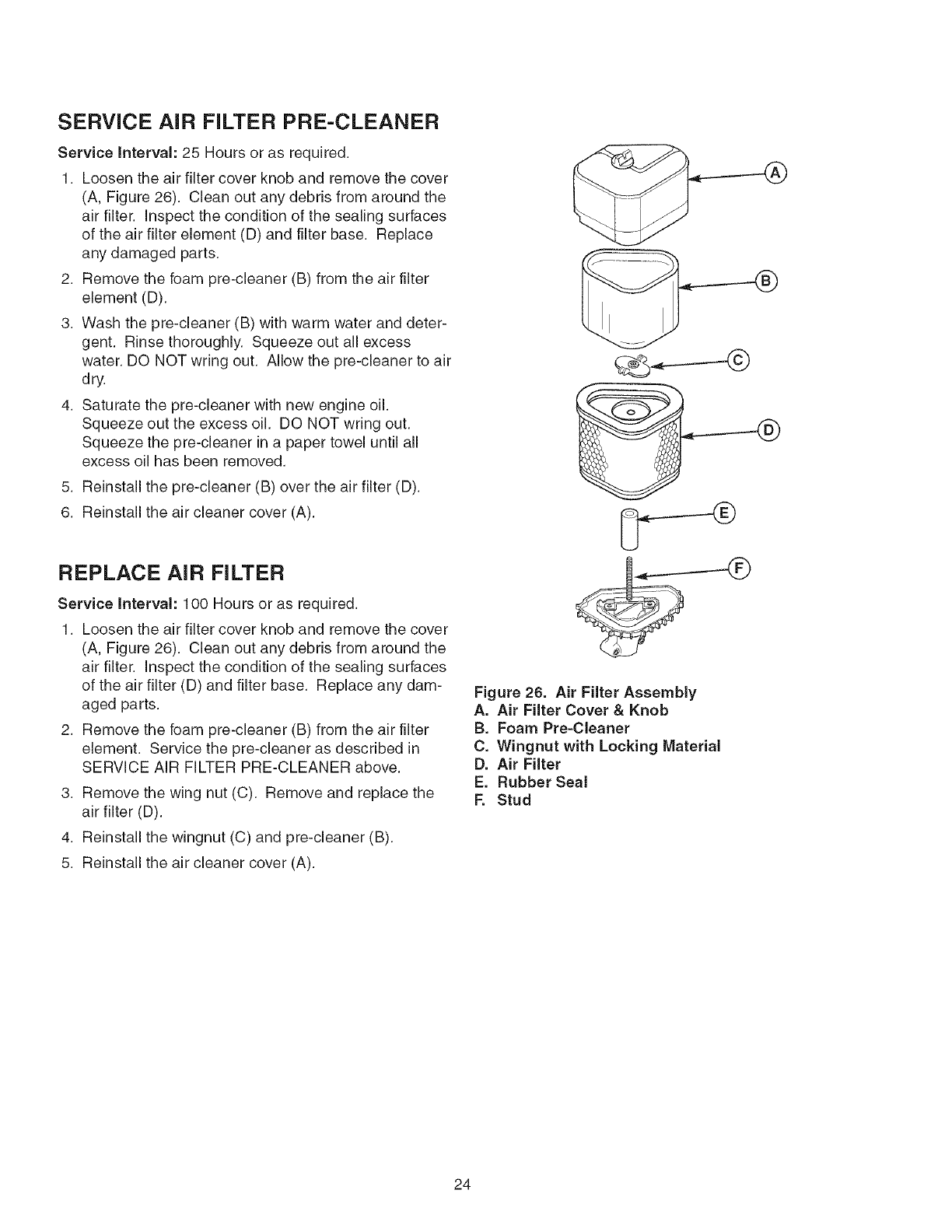
Figure 26. Air Filter Assembly
A. Air Filter Cover & Knob
B. Foam Pre-Cleaner
C. Wingnut with Locking Material
D. Air Filter
E. Rubber Seal
F. Stud
24
REPLACE SPARK PLUG
Service Interval: 200 Hours.
Replacement Spark Plug: Champion RC12YC or equiv-
alent
Spark Plug Gap: .040" (lmm)
1. Stop the engine and allow it to cool.
2. Clean the area around the spark plug (A, Figure 28).
3. Remove the spark plug and inspect it. If at all dam-
aged or worn, replace it.
4. Check the spark plug gap. The gap (new or used
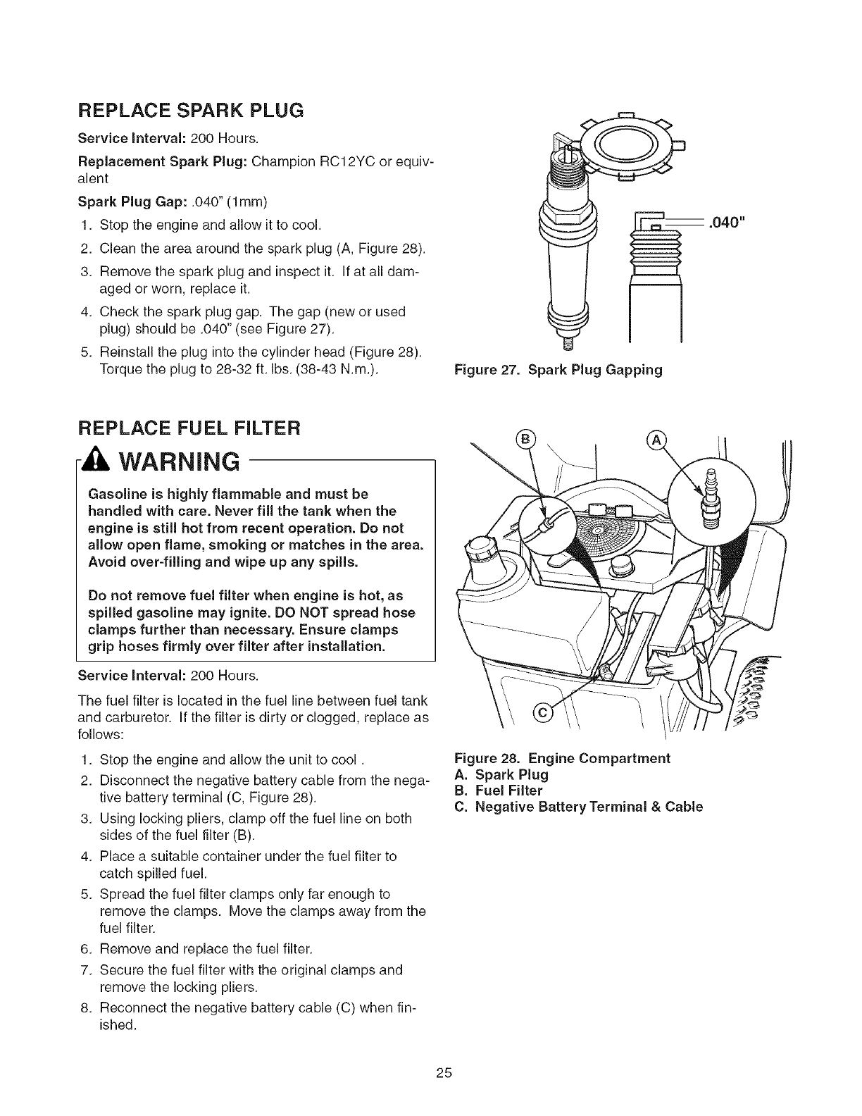
plug) should be .040" (see Figure 27).
5. Reinstall the plug into the cylinder head (Figure 28).
Torque the plug to 28-32 ft. Ibs. (38-43 N.m.). Figure 27. Spark Plug Gapping
-- .040"
REPLACE FUEL FILTER
WARNING
Gasoline is highly flammable and must be
handled with care. Never fill the tank when the
engine is still hot from recent operation. Do not
allow open flame, smoking or matches in the area.
Avoid over=filling and wipe up any spills.
Do not remove fuel filter when engine is hot, as
spilled gasoline may ignite. DO NOT spread hose
clamps further than necessary. Ensure clamps
grip hoses firmly over filter after installation.
Service Interval: 200 Hours.
The fuel filter is located in the fuel line between fuel tank
and carburetor. If the filter is dirty or clogged, replace as
follows:
1. Stop the engine and allow the unit to cool.
2. Disconnect the negative battery cable from the nega-
tive battery terminal (C, Figure 28).
3. Using locking pliers, clamp off the fuel line on both
sides of the fuel filter (B).
4. Place a suitable container under the fuel filter to
catch spilled fuel.
5. Spread the fuel filter clamps only far enough to
remove the clamps. Move the clamps away from the
fuel filter.
6. Remove and replace the fuel filter.
7. Secure the fuel filter with the original clamps and
remove the locking pliers.
8. Reconnect the negative battery cable (C) when fin-
ished.
Figure 28. Engine Compartment
A. Spark Plug
B. Fuel Filter
C. Negative Battery Terminal & Cable
25
\/
\
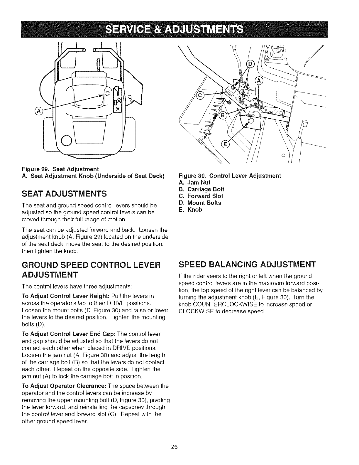
Figure 29. Seat Adjustment
A. Seat Adjustment Knob (Underside of Seat Deck)
SEAT ADJUSTMENTS
The seat and ground speed control levers should be
adjusted so the ground speed control levers can be
moved through their full range of motion.
The seat can be adjusted forward and back. Loosen the
adjustment knob (A, Figure 29) located on the underside
of the seat deck, move the seat to the desired position,
then tighten the knob.
Figure 30. Control Lever Adjustment
A. Jam Nut
B. Carriage Bolt
C. Forward Slot
D. Mount Bolts
E. Knob
GROUND SPEED CONTROL LEVER
ADJUSTMENT
The control levers have three adjustments:
To Adjust Control Lever Height: Pull the levers in
across the operator's lap to their DRIVE positions.
Loosen the mount bolts (D, Figure 30) and raise or lower
the levers to the desired position. Tighten the mounting
bolts.(D).
To Adjust Control Lever End Gap: The control lever
end gap should be adjusted so that the levers do not
contact each other when placed in DRIVE positions.
Loosen the jam nut (A, Figure 30) and adjust the length
of the carriage bolt (B) so that the levers do not contact
each other. Repeat on the opposite side. Tighten the
jam nut (A) to lock the carriage bolt in position.
To Adjust Operator Clearance: The space between the
operator and the control levers can be increase by
removing the upper mounting bolt (D, Figure 30), pivoting
the lever forward, and reinstalling the capscrew through
the control lever and forward slot (C). Repeat with the
other ground speed lever.
SPEED BALANCING ADJUSTMENT
If the rider veers to the right or left when the ground
speed control levers are in the maximum forward posi-
tion, the top speed of the right lever can be balanced by
turning the adjustment knob (E, Figure 30). Turn the
knob COUNTERCLOCKWISE to increase speed or
CLOCKWISE to decrease speed
26
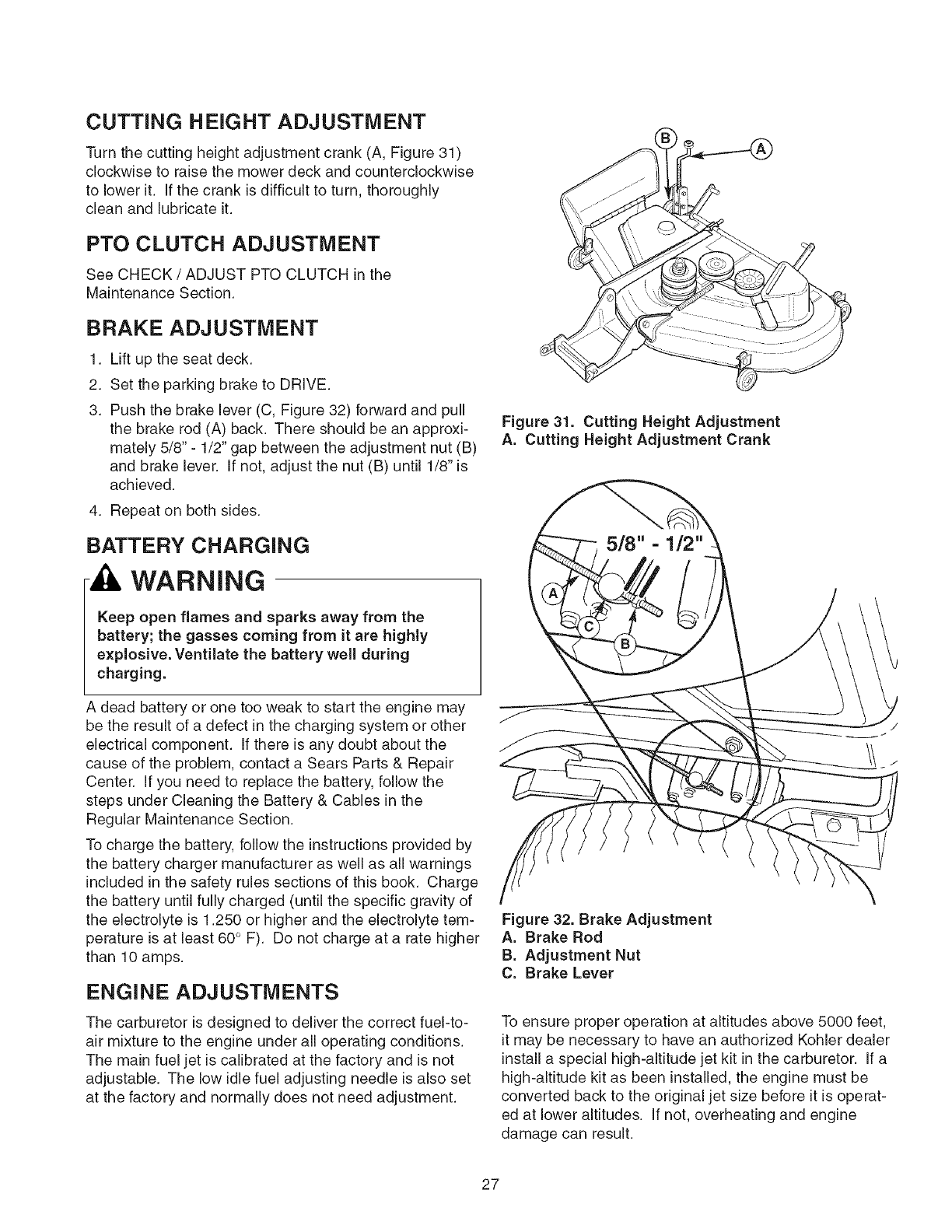
CUTTING HEIGHT ADJUSTMENT
Turn the cutting height adjustment crank (A, Figure 31)
clockwise to raise the mower deck and counterclockwise
to lower it. If the crank is difficult to turn, thoroughly
clean and lubricate it.
PTO CLUTCH ADJUSTMENT
See CHECK /ADJUST PTO CLUTCH in the
Maintenance Section.
BRAKE ADJUSTMENT
1. Lift up the seat deck.
2. Set the parking brake to DRIVE.
3. Push the brake lever (C, Figure 32) forward and pull
the brake rod (A) back. There should be an approxi-
mately 5/8" - 1/2" gap between the adjustment nut (B)
and brake lever. If not, adjust the nut (B) until 1/8" is
achieved.
4. Repeat on both sides.
BATTERY CHARGING
WARNING
Keep open flames and sparks away from the
battery; the gasses coming from it are highly
explosive. Ventilate the battery well during
charging.
A dead battery or one too weak to start the engine may
be the result of a defect in the charging system or other
electrical component. If there is any doubt about the
cause of the problem, contact a Sears Parts & Repair
Center. If you need to replace the battery, follow the
steps under Cleaning the Battery & Cables in the
Regular Maintenance Section.
To charge the battery, follow the instructions provided by
the battery charger manufacturer as well as all warnings
included in the safety rules sections of this book. Charge
the battery until fully charged (until the specific gravity of
the electrolyte is 1.250 or higher and the electrolyte tem-
perature is at least 60° F). Do not charge at a rate higher
than 10 amps.
ENGINE ADJUSTMENTS
The carburetor is designed to deliver the correct fuel-to-
air mixture to the engine under all operating conditions.
The main fuel jet is calibrated at the factory and is not
adjustable. The low idle fuel adjusting needle is also set
at the factory and normally does not need adjustment.
Figure 31. Cutting Height Adjustment
A. Cutting Height Adjustment Crank
Figure 32. Brake Adjustment
A. Brake Rod
B. Adjustment Nut
C. Brake Lever
To ensure proper operation at altitudes above 5000 feet,
it may be necessary to have an authorized Kohler dealer
install a special high-altitude jet kit in the carburetor. If a
high-altitude kit as been installed, the engine must be
converted back to the original jet size before it is operat-
ed at lower altitudes. If not, overheating and engine
damage can result.
27
MOWER DECK LEVELING
ADJUSTMENTS
WARNING
Before checking mower, shut off PTO and engine.
Allow all moving parts to stop. Remove ignition
key, then disconnect the spark plug wire and
fasten it away from the spark plug.
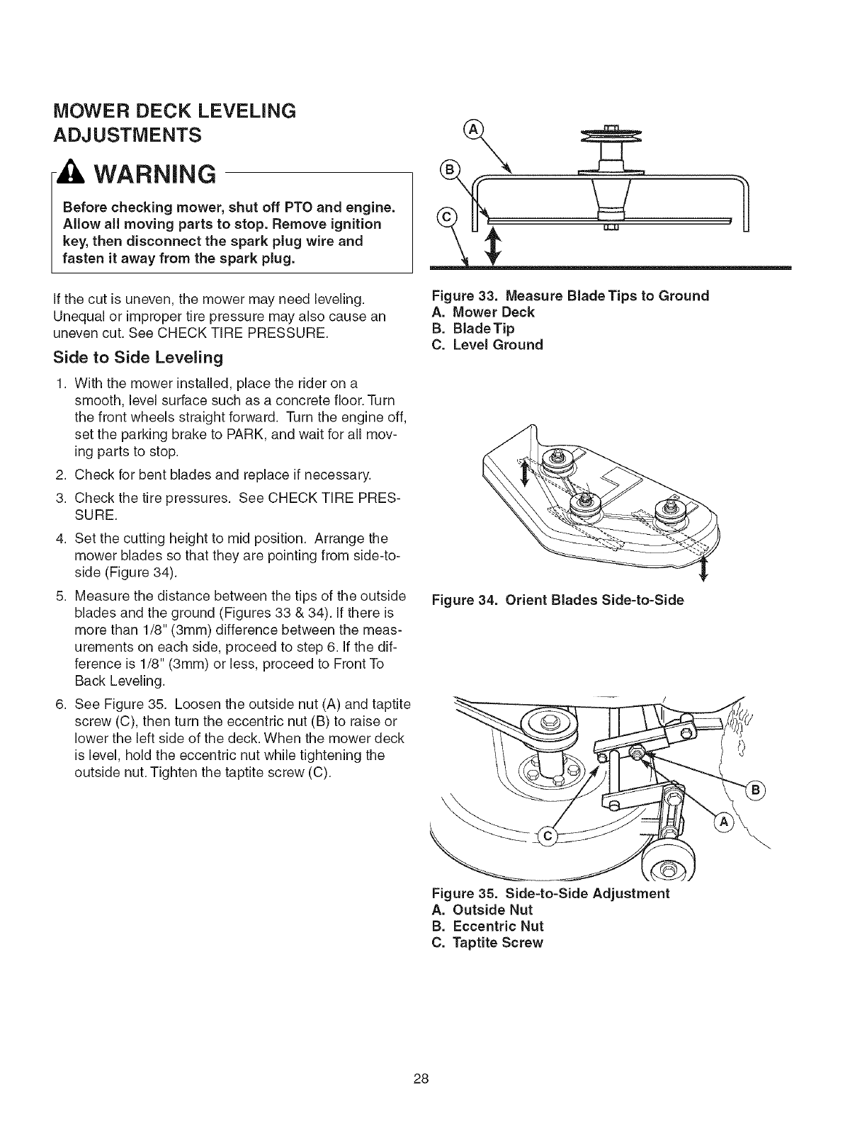
If the cut is uneven, the mower may need leveling.
Unequal or improper tire pressure may also cause an
uneven cut. See CHECK TIRE PRESSURE.
Side to Side Leveling
1. With the mower installed, place the rider on a
smooth, level surface such as a concrete floor. Turn
the front wheels straight forward. Turn the engine off,
set the parking brake to PARK, and wait for all mov-
ing parts to stop.
2. Check for bent blades and replace if necessary.
3. Check the tire pressures. See CHECK TIRE PRES-
SURE.
4. Set the cutting height to mid position. Arrange the
mower blades so that they are pointing from side-to-
side (Figure 34).
5. Measure the distance between the tips of the outside
blades and the ground (Figures 33 & 34). If there is
more than 1/8" (3mm) difference between the meas-
urements on each side, proceed to step 6. If the dif-
ference is 1/8" (3mm) or less, proceed to Front To
Back Leveling.
6. See Figure 35. Loosen the outside nut (A) and taptite
screw (C), then turn the eccentric nut (B) to raise or
lower the left side of the deck. When the mower deck
is level, hold the eccentric nut while tightening the
outside nut. Tighten the taptite screw (C).
\
u,3,1
Figure 33. Measure BladeTips to Ground
A. Mower Deck
B. Blade Tip
C. Level Ground
Figure 34. Orient Blades Side-to-Side
Figure 35. Side-to-Side Adjustment
A. Outside Nut
B. Eccentric Nut
C. Taptite Screw
28
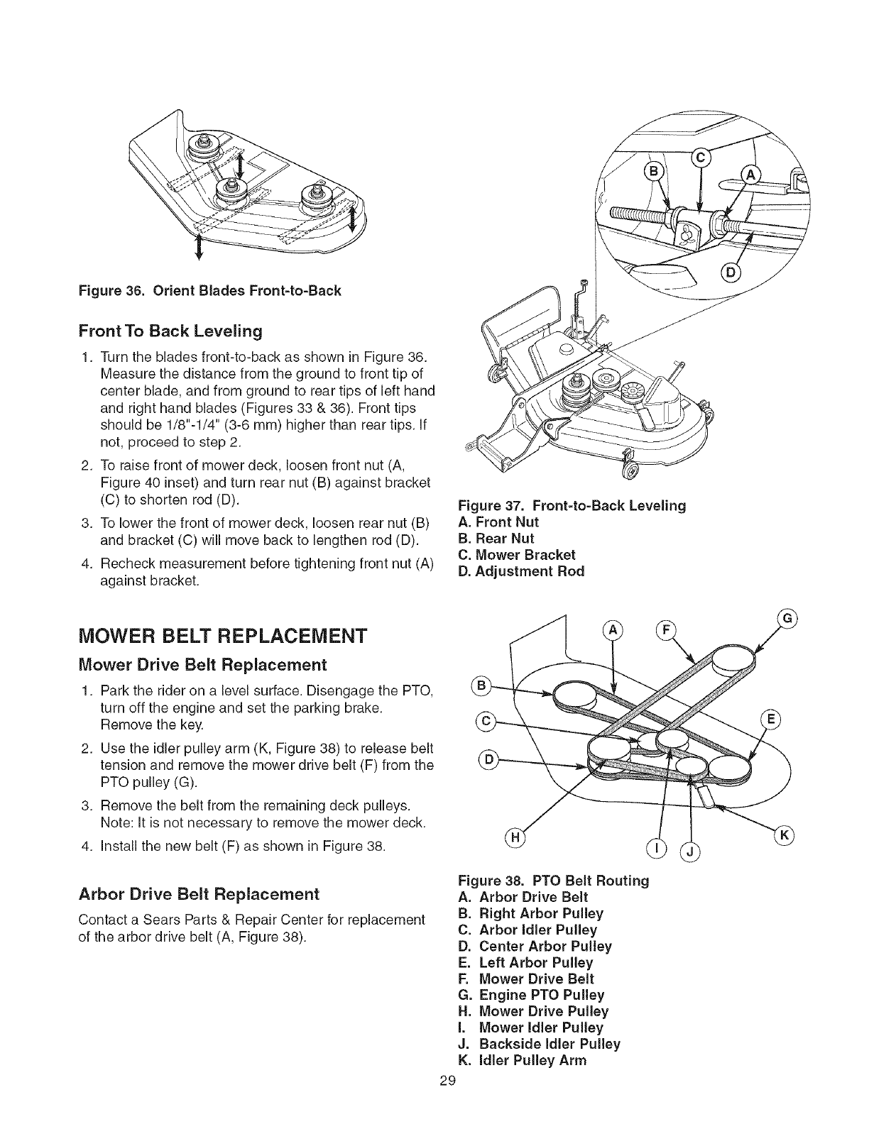
Figure 36. Orient Blades Front-to-Back
Front To Back Leveling
1. Turn the blades front-to-back as shown in Figure 36.
Measure the distance from the ground to front tip of
center blade, and from ground to rear tips of left hand
and right hand blades (Figures 33 & 36). Front tips
should be 1/8"-1/4" (3-6 mm) higher than rear tips. If
not, proceed to step 2.
2. To raise front of mower deck, loosen front nut (A,
Figure 40 inset) and turn rear nut (B) against bracket
(C) to shorten rod (D).
3. To lower the front of mower deck, loosen rear nut (B)
and bracket (C) will move back to lengthen rod (D).
4. Recheck measurement before tightening front nut (A)
against bracket.
Figure 37. Front=to=Back Leveling
A. Front Nut
B. Rear Nut
C. Mower Bracket
D. Adjustment Rod
MOWER BELT REPLACEMENT
Mower Drive Belt Replacement
1. Park the rider on a level surface. Disengage the PTO,
turn off the engine and set the parking brake.
Remove the key.
2. Use the idler pulley arm (K, Figure 38) to release belt
tension and remove the mower drive belt (F) from the
PTO pulley (G).
3. Remove the belt from the remaining deck pulleys.
Note: It is not necessary to remove the mower deck.
4. Install the new belt (F) as shown in Figure 38.
Arbor Drive Belt Replacement
Contact a Sears Parts & Repair Center for replacement
of the arbor drive belt (A, Figure 38).
Figure 38. PTO Belt Routing
A. Arbor Drive Belt
B. Right Arbor Pulley
C. Arbor Idler Pulley
D. Center Arbor Pulley
E. Left Arbor Pulley
F. Mower Drive Belt
G. Engine PTO Pulley
H. Mower Drive Pulley
I. Mower Idler Pulley
J. Backside Idler Pulley
K. Idler Pulley Arm
29
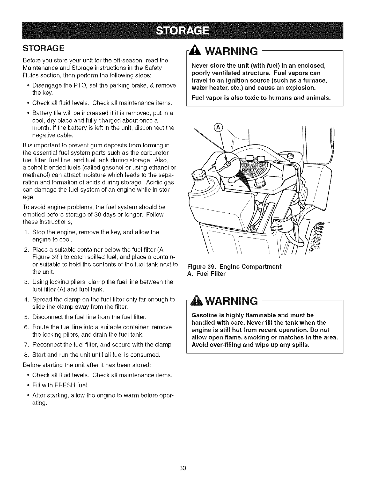
STO RAG E
Before you store your unit for the off-season, read the
Maintenance and Storage instructions in the Safety
Rules section, then perform the following steps:
• Disengage the PTO, set the parking brake, & remove
the key.
Check all fluid levels. Check all maintenance items.
WARNING
Never store the unit (with fuel) in an enclosed,
poorly ventilated structure. Fuel vapors can
travel to an ignition source (such as a furnace,
water heater, etc.) and cause an explosion.
Fuel vapor is also toxic to humans and animals.
• Battery life will be increased if it is removed, put in a
cool, dry place and fully charged about once a
month. If the battery is left in the unit, disconnect the
negative cable.
It is important to prevent gum deposits from forming in
the essential fuel system parts such as the carburetor,
fuel filter, fuel line, and fuel tank during storage. Also,
alcohol blended fuels (called gasohol or using ethanol or
methanol) can attract moisture which leads to the sepa-
ration and formation of acids during storage. Acidic gas
can damage the fuel system of an engine while in stor-
age.
To avoid engine problems, the fuel system should be
emptied before storage of 30 days or longer. Follow
these instructions;
1. Stop the engine, remove the key, and allow the
engine to cool.
2. Place a suitable container below the fuel filter (A,
Figure 39") to catch spilled fuel, and place a contain-
er suitable to hold the contents of the fuel tank next to
the unit.
3. Using locking pliers, clamp the fuel line between the
fuel filter (A) and fuel tank.
4. Spread the clamp on the fuel filter only far enough to
slide the clamp away from the filter.
5. Disconnect the fuel line from the fuel filter.
6. Route the fuel line into a suitable container, remove
the locking pliers, and drain the fuel tank.
7. Reconnect the fuel filter, and secure with the clamp.
8. Start and run the unit until all fuel is consumed.
Figure 39. Engine Compartment
A. Fuel Filter
WARNING
Gasoline is highly flammable and must be
handled with care. Never fill the tank when the
engine is still hot from recent operation. Do not
allow open flame, smoking or matches in the area.
Avoid over-filling and wipe up any spills.
Before starting the unit after it has been stored:
Check all fluid levels. Check all maintenance items.
• Fill with FRESH fuel.
• After starting, allow the engine to warm before oper-
ating.
3O

While normal care and regular maintenance will extend the life
of your equipment, prolonged or constant use may eventually
require that service be performed to allow it to continue operat-
ing properly. The troubleshooting guide below lists the most
common problems, their causes and remedies.
If you prefer, all of these procedures can be performed for you
by a Sears Parts & Repair Center. See the back cover for
important Sears Parts & Repair Center information.
,WARNING
To avoid serious injury, perform maintenance on
the rider or mower only when the engine is
stopped and the parking brake set to PARK.
Always remove the ignition key, disconnect the
spark plug wire and fasten it away from the plug
before beginning the maintenance, to prevent
accidental starting of the engine.
Troubleshooting the Rider
PROBLEM CAUSE REMEDY
Engine will Parking brake not set to PARK Set parking brake to PARK.
not turnover PTO switch in ON position. Place in OFF position.
or start. Ground speed levers not in PARK positions. Move ground speed levers to PARK positions.
Throttle not in CHOKE position. Move throttle to CHOKE position.
Key not turned fully to START position. Turn key fully to START position.
Out of fuel. If engine is hot, allow it to cool, then refill the fuel
tank.
Engine flooded. Move throttle control back to FULL position to open
the choke.
Gas is old or stale. Drain fuel & replace with fresh fuel. See Storage.
Water in fuel. Drain fuel & refill with fresh fuel. See Storage.
Battery terminals require cleaning. Clean the battery terminals
Battery discharged or dead. Recharge or replace.
Spark plug(s) faulty, fouled or incorrectly Clean and gap or replace.
gapped.
Wiring loose or broken. Visually check wiring & replace broken or frayed
wires. Tighten loose connections.
Solenoid or starter motor faulty. Replace. Contact Sears Parts & Repair.
Safety interlock switch faulty. Replace. Contact Sears Parts & Service.
Engine starts Air filter plugged Service pre-cleaner and/or replace air filter ele-
hard or runs ment.
poorly. Throttle set to CHOKE position longer than Set throttle to FULL position.
necessary.
Spark plug faulty, fouled, or incorrectly gapped. Clean and gap or replace.
Engine Low oil level. Check/add oil as required.
knocks. Using wrong grade oil. See "Change Engine Oil" in the Maintenance
Section.
Excessive oil Engine running too hot. Clean engine cooling fins, blower screen and air
consumption, cleaner.
Using wrong weight oil. See "Change Engine Oil" in the Maintenance
Section.
Too much oil in crankcase. Drain excess oil.
Engine Dirty air filter. Replace air filter. See "Replace Air Filter Element."
exhaust is
black. Engine choke control is in closed position. Open choke control.
31

Engineruns, but
rider will not
drive.
Rider drive belt
slips.
Parking brake
will not hold.
Rider steers or
handles poorly.
Rider tracks to
one side.
Transmission release levers in PUSH
9ositions.
Drive belt slips.
Belt is broken.
Parking brake is not fully released.
Pulleys or belt greasy or oily.
Belt stretched or worn.
Parking brake is incorrectly adjusted.
Improper tire inflation.
Steering linkage is loose.
Ground speed adj. knobs not adjusted.
Move levers to DRIVE positions.
Clean or replace belt as necessary.
Replace drive belt. Contact Sears Parts & Repair.
Contact Sears Parts & Repair.
Clean as required.
Replace belt. Contact Sears Parts & Repair.
See Service & Adjustments Section.
See Maintenance Section.
Check and tighten any loose connections.
See SPEED BALANCING ADJUSTMENT
Troubleshooting
PROBLEM
Mower cutting
height difficult to
adjust.
Mower cut is
uneven.
Mower cut is rough
looking.
Engine stalls easily
with mower
engaged.
Excessive mower
vibration.
Mower drive belt
slips or fails to
drive.
the Mower
CAUSE
Cutting height crank threads dirty or
require lube.
Rider tires not inflated equally or properly.
Mower not leveled properly.
Engine speed too slow.
Ground speed too fast.
Blades are dull.
Mower drive belt slipping because it is oily
or worn.
Blades not properly fastened to arbors.
Engine speed too slow.
Ground speed too fast.
Cutting height set too low.
Underside of mower deck dirty.
Discharge chute jamming with cut grass.
Blade mounting bolts are loose.
Mower blades, arbors, or pulleys are bent.
Mower blades are out of balance.
Belt installed incorrectly.
Idler pulley spring broken or not properly
attached.
Mower drive belt broken.
PTO clutch out of adjustment.
REMEDY
Thoroughly clean and lubricate cutting height crank
with oil.
See Maintenance Section.
See "Mower Leveling" in Service & Adjustments.
Set throttle to FULL when mowing.
Decrease Ground Speed.
Sharpen or replace blades. See Maintenance
Section.
Clean or replace belt as necessary.
See "Check/Replace Mower Blades" in Maintenance
Section.
Set to FULL throttle.
Decrease Ground Speed.
Cut tall grass at maximum cutting height during first
)ass.
Remove mower deck and clean underside.
Cut grass with discharge pointing toward previously
cut area.
Tighten to 45-55 ft. Ibs. (61-75 N.m.).
Check and replace as necessary.
Replace or balance blades. See Maintenance
Section.
Reinstall Correctly.
Repair or replace as needed.
Replace drive belt.
Adjust PTO clutch. See Maintenance Section.
32
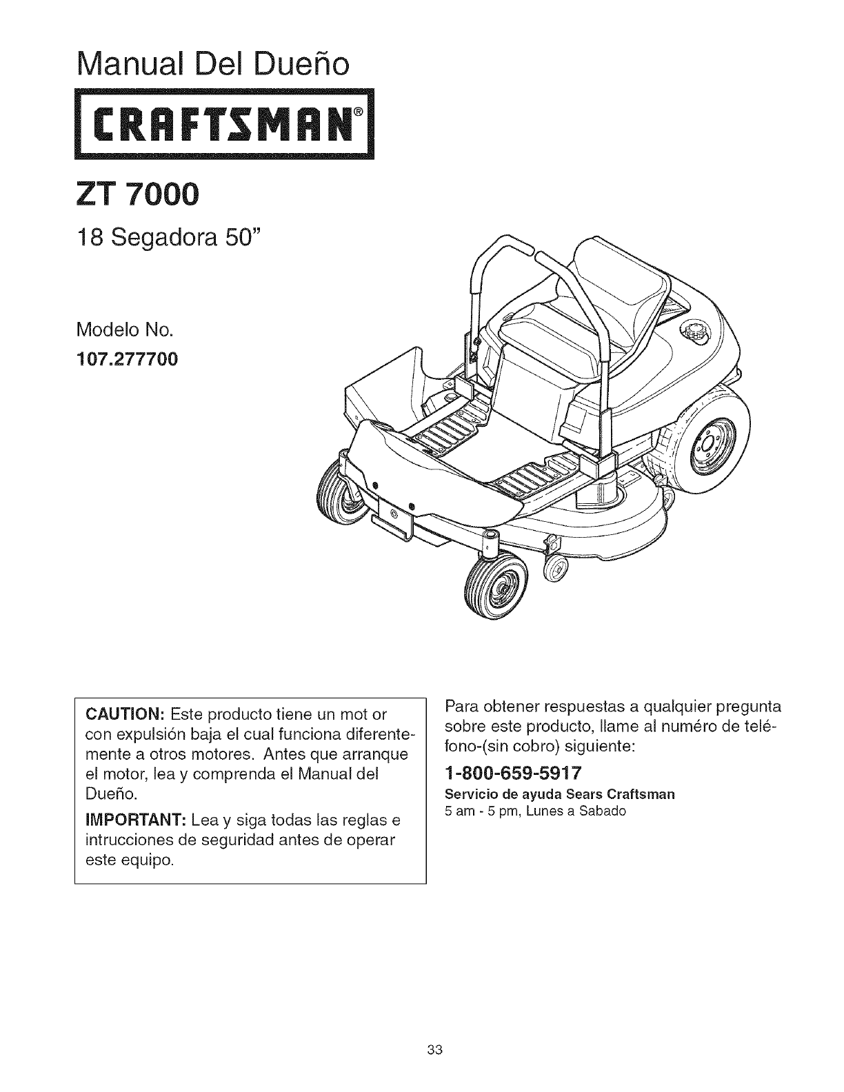
Manual Del Dueho
ZT 7OOO
18 Segadora 50"
Modelo No.
107.277700
CAUTION: Este producto tiene un mot or
con expulsi6n baja el cua! funciona diferente-
mente a otros motores. Antes que arranque
el motor, lea y comprenda el Manual del
Due5o.
IMPORTANT: Lea y siga todas las reglas e
intrucciones de seguridad antes de operar
este equipo.
Para obtener respuestas a qualquier pregunta
sobre este producto, Ilame al num6ro de tel&
fono-(sin cobro) siguiente:
1-800-659-5917
Servicio de ayuda Sears Craftsman
5 am - 5 pro, Lunes a Sabado
33
Declaraci6nde Garantia ........................................... 34
Reglas eInformaci6n de Seguridad ........................ 35
NQrneros de Identificaci6n ........................................ 39
Accesorios Opcionales ............................................. 40
Contenido del Paquete de Literatura ....................... 40
Pre-Operaci6n ............................................................ 41
Operaci6n ................................................................... 42
Mantenimiento ........................................................... 49
Servicio y Ajustes ...................................................... 58
AImacenamiento ........................................................ 62
Diagn6stico ................................................................ 63
Partes de Refacci6n ............................................ PTS-1
NOTA: En este manual, "izquierda" y "derecha" se refieren segdn como se vea desde la posicidn de operacidn.
GARANTIA LIMITADA DEL EQUIPO MONTABLE DE CRAFTSMAN
Pot dos (2) aOos a partir de la fecha de compra, si este equipo montable de Craftsman es mantenido, lubricado y afinado
conforme alas instrucciones en el manual del propietario, Sears repararb, o reemplazarb, sin costo alguno cualquier parte
que se encuentre defectuosa en material o mano de obra conforme a los lineamientos de la cobertura enumerada a contin-
uaciOn. Sears tambiOn proporcionarb, mano de obra gratis pot las partes garantizadas que apliquen durante estos dos aOos
completos. Durante los primeros 30 dias de compra, no habrb,cargos para dar servicio al producto en su domicilio pot
problemas cubiertos pot esta garanfia. (Vea las excepciones abajo). Para su conveniencia, el servicio de garanfia A DOMI-
ClLIO seguirb,estando disponible despuOs de los primeros 30 dias de compra, pero habrb, un cargo pot el recorrido. Este
cargo quedarA anulado si se Ileva el producto Craftsman en uno de los lugares autorizados de Sears. Para averiguar cub,I
es el Sears mb,s cercano a usted, le rogamos que Ilame a 1-800-MY-HOME. Esta garanfia aplica s01omientras el producto
est6 dentro de los Estados Unidos.
ESTA GARANTiA NO CUBRE:
*Arficulos consumibles que se desgastan con el uso
normal, Io que incluye, entre otros las aspas, bujias, ill-
tros de aire, bandas y filtros de aceite.
. Servicio por mantenimiento estandar, cambios de
aceite y afinaciones.
Reemplazo o reparaciOn de Ilantas causado por pon-
chaduras de objetos externos, como clavos, pOas,
troncos cortados o vidrio.
-Las reparaciones necesarias por abuso del operador,
Io que incluye, entre otros, daOos causados por remol-
car objetos que sobrepasan las capacidades del
equipo montable, impacto contra objetos que doblen el
bastidor o cigQeOal o exceder la velocidad del motor.
Las reparaciones necesarias por negligencia del oper-
ador, Io que incluye, entre otros, daOos el6ctricos y
mecb,nicos causados por el almacenamiento inadecua-
do, no usar el grado y la cantidad adecuada de aceite
para motor, no mantener la cubierta libre de despojos
inflamables o no mantener el equipo conforme a las
instrucciones contenidas en el manual del propietario.
•La limpieza del motor (instalaci6n de combustible) o
reparaciOn causada por gasolina que se decide esta
contaminada u oxidada (viciada). En general, el com-
bustible debe usarse en un lapso de 30 dias de su
fecha de compra.
•El deterioro y desgaste normal de los acabados del
exterior ni el reemplazo de las etiquetas del producto.
Cuando el equipo montable que se usa con fines co-
merciales o de alquiler.
GARANTIA LIMITADA DE LA BATERIA
Por noventa (90) dias a partir de la fecha de compra, si la bateria incluida con este equipo montable prueba estar defectu-
osa en material o mano de obra y nuestras pruebas determinan que la bateria no retiene la carga; Sears reemplazarb, la
bateria sin cargos. Durante los pfimeros 30 dias de compra, no habrb, cargos para reemplazar la bateria en su DOMICILIO.
DespuOs de los pfimeros 30 dias, para su conveniencia, el servicio de garantia A DOMIClLIO seguirb,estando disponible,
pero habr_ un cargo pot el recorrido. Este cargo quedarb, anulado si se Ileva el producto Craftsman en uno de los lugares
autorizados de Sears. PARA AVERIGUAR CUA,L ES EL SEARS MA,S CERCANO A USTED, LE ROGAMOS QUE LLAME
A 1-800-MY-HOME. Esta garantia de la bateria aplica s01omientras el producto est6 dentro de los Estados Unidos.
Esta garantia le otorga derechos legales especificos, pero es posible que usted tenga otros derechos, los cuales varian de
un estado a otro.
Sears, Roebuck and Co., Dept. 817WA, Hoffman Estates, IL 60179
34
Lea estas reglas de seguridad y sigalas con cuidado. No obedecer estas reglas puede resultar en la perdida del control
sobre la unidad, lesiones severas a la persona o la muerte de usted o espectadores, o dahos a la propiedad o al equipo.
Esta cubierta de la podadora es capaz de amputar manos "t/pies V de arrojar objetos.
El trib,ngulo ,_ en el texto denota _recauciones o advertencias importantes que deben seguirse.
OPERACJON GENERAL
t. Lea, entienda y siga todas las instrucciones en el
manual y en la unidad antes de arrancar.
2. No coloque las manos o pies cerca de las partes
giratofias o debajo de la mAquina. Mantengase aleja-
do de la abertura de expulsi6n en todo momento.
3. S61opermita que un adulto responsable, que este
familiarizado con las instrucciones, opere la unidad
(los reglamentos locales pueden restringir la edad del
operador).
4. Retire del Area objetos tales como piedras, juguetes,
etc., que pueden ser cogidos y arrojados por las aspas.
5. AsegOrese de que el Area est6 libre de otra gente
antes de podar el c6sped. Detenga la unidad si
alguien entra en el Area.
6. Nunca Ileve pasajeros.
7. No pode el c6sped en reversa a menos que sea
absolutamente necesario. Siempre mire hacia abajo y
hacia atrAs antes de meter reversa y mientras Io hace.
8. Nunca descargue el material directamente hacia alguien.
Evite descargar el material contra una pared u obstrucci6n.
El material puede rebotar hacia el operador. Detenga las
aspas cuando cruce pot superficies cubiertas de grava.
9. No opere la maquina sin el recogedor completo de
hierba, guarda de descarga (deflector) ni otros dis-
positivos de seguridad en su lugar.
10. Baje la velocidad antes de dar la vuelta.
11. Nunca deje la unidad operando sin supervisi6n.
Siempre desacople el PTO, ponga el freno de mano,
detenga el motor y quite las Ilaves antes de desmontar.
12. Desacople las aspas (PTO) cuando no este podando
el c6sped. Apague el motor y espere a que todas las
partes se detengan pot completo antes de limpiar la
mAquina, quitar el recolector de hierba o desatascar
la guarda de la descarga.
13. Opere la mAquina s61o a la luz del dia o con buena
luz artificial.
14. No opere la unidad mientras est6 bajo la influencia de
alcohol o drogas.
15 Tenga cuidado con el trafico si opera cerca de alguna calle.
16. Sea extremadamente cuidadoso al cargar o descar-
gar la unidad en un remolque o camioneta.
17. Siempre prot6jase los ojos cuando opere esta unidad.
18. Los datos indican que operadores, de 60 a_os y mas,
estan involucrados en un gran porcentaje de lesiones
asociadas con podadoras montables. Estos oper-
adores deberian evaluar su habilidad de operar la
podadora montable con la suficiente seguridad para
protegerse a si mismos y a otros de lesiones.
19. Siga las recomendaciones del fabficante respecto a
los pesos y contrapesos para Ilantas.
20. Recuerde que el operador es responsable de los
accidentes que ocurran a otra gente o propiedad.
21. Todos los conductores deberian pedir y obtener
instrucciones profesionales y prActicas.
22. Siempre use zapatos cerrados y pantalones. Nunca
opere la unidad descalzo o usando sandalias.
23. Antes de su uso, siempre verifique visualmente que
las aspas y sus aditamentos est6n presentes, intac-
tos y afianzados. Reemplace las partes daSadas o
desgastadas.
24. Desacople los accesorios antes de: poner combustible,
retirar un accesofio, hacer ajustes (a menos que el
ajuste puede hacerse desde la posici6n del operador).
25. Cuando la maquina esta estacionada, almacenada o
se deja sin supervisi6n, baje los medios de corte a
menos que se use una traba mecAnica positiva.
26. Antes de dejar la posici6n del operador pot cualquier
raz6n, accione el freno de mano, desacople el PTO,
detenga el motor y quite la Ilave.
27. Para reducir el peligro de incendio, mantenga la
unidad libre de c6sped, hojas y aceite excesivo. No
se detenga ni estacione sobre hojas secas, cesped o
matefiales combustibles.
28. Usar u operar un motor sobre o cerca de tierras
cubiertas de bosques, matorrales o cesped es una
violaci6n de la Secci6n 4442 del C6digo de Recursos
POblicos de California a menos que el sistema de
escape est6 equipado con parachispas que cumpla
con las leyes locales o estatales aplicables. Es posi-
ble que otras Areas estatales o federales tengan
leyes similares.
TRANSPORTE YALIVIACENAIVIIENTO
t. Cuando se transporta la unidad sobre un remolque
abierto, aseg0rese de que mire hacia eJfrente, en
direcci6n del desplazamiento. Si la unidad esta mirando
hacia atras, la fuerza del aire puede daSar la unidad.
2. Siempre obedezca las prActicas seguras de rellena-
do y manejo de combustible al poner combustible al
tractor despu6s del transporte o almacenamiento.
3. Nunca almacene la unidad (con combustible) en una
estructura cerrada con poca ventilaci6n. Los vapores
del combustible pueden viajar a una fuente de igni-
ci6n (como un homo, calentador de agua, etc.) y oca-
sionar una explosi6n. Los vapores del combustible
tambi6n son t6xicos para los humanos y animales.
4. Siempre siga las instrucciones del manual del oper-
ador respecto alas preparaciones de almacenamien-
to antes de almacenar el tractor ya sea pot periodos
cortos o largos.
5. Siempre siga las instrucciones del manual del motor
respecto a procedimientos apropiados de arranque
cuando reintegre la unidad al servicio.
6. Nunca almacene la unidad ni el contenedor de com-
bustible adentro, donde haya una llama abierta o
piloto, como el de un calentador de agua. Permita
que la unidad se enfrie antes de almacenarla.
TP 600-2459-06-UV-SIvIA
35

OPERACION EN CUESTAS
Las cuestas son un factor importante relacionado con los acci-
dentes pot perdida de control y volcaduras, Io cual puede resultar
en lesiones severas o la muerte. Cualquier operaci6n en cuestas
exige precauciones extremas. Si usted no puede dar marcha
atrAs en una cuesta o se siente inquieto en ella, no opere en ella.
No se puede recuperar el control de una mgtquina montable que
se desliza pot una cuesta al accionar el freno. Las principales
razones de perdida de control son: agarre insuficiente de las Ilan-
tas en la tierra, velocidad demasiado alta, frenado inadecuado, el
tipo de mgtquina es inadecuada para la labor, falta de conocimien-
to sobre las condiciones de la tierra, enganche incorrecto y dis-
tribuci6n de la carga.
1. Pode el cesped de la cuesta de arriba hacia abajo y vicever-
sa, no de un lado al otro.
2. Tenga con cuidado con los baches, rafces o topes. Un terreno
accidentado puede volcar la unidad. El cesped alto puede
ocultar obsta.culos.
3. Opte pot una velocidad lenta de modo que no tenga que
detenerse o cambiar de velocidad mientras este en la cuesta.
4. No pode cesped mojado. Las Ilantas pueden perder la trac-
ci6n.
5. Siempre mantenga la unidad con el cambio puesto en espe-
cial al viajar cuesta abajo. No cambie a neutral para
deslizarse cuesta abajo.
6. Evite arrancar, detenerse o dar la vuelta sobre una cuesta. Si
las Ilantas pierden la tracci6n, desacople las aspas y proceda
lentamente directo cuesta abajo.
7. Mantenga todos los movimientos en la cuesta lentos y grad-
uales. No haga cambios repentinos de velocidad o direcci6n,
que pueden hacer que vuelque la mgtquina.
8. Sea extremadamente cuidadoso mientras opera las
mgtquinas con recolectores de hierba u otros accesorios;
estos pueden afectar la estabilidad de la unidad.
9. No intente estabilizar la mgtquina poniendo el pie en el piso.
10. No pode el cesped cerca de barrancos, zanjas o diques. La
podadora podrfa volcarse repentinamente si una Ilanta cae
por la orilla de un acantilado o zanja o si se derrumba una orilla.
11. No use los recolectores de hierba en cuestas pronunciadas.
12. No pode cuestas en las cuales no pueda dar marcha atrgts.
13. Vea a su distribuidor autorizado respecto a recomendaciones
sobre pesos o contrapesos para Ilantas para mejorar la esta-
bilidad.
14. Quite obstgtculos tales como piedras, ramas de &rboles, etc.
15. Use la velocidad lenta. Las Ilantas pueden perder la tracci6n
en las cuestas aun cuando los frenos funcionan debidamente.
16. No de vuelta en una cuesta a menos que sea necesario, y
entonces, gire lenta y gradualmente cuesta abajo, si es posible.
EQUIPO REMOLCADO
1. Remolque s61o con una mAquina que tiene un
enganche diseSado para remolcar. No enganche el
equipo remolcado excepto en el punto del enganche.
2. Siga las recomendaciones del fabricante respecto al
limite de peso para el equipo remolcado y el declive
de remolcado.
3. Nunca permita que los niSos u otros se suban al
equipo remolcado.
4. En las cuestas, el peso del equipo remolcado puede
ocasionar p6rdida de tracci6n y p_rdida de control.
5. TraslAdese lentamente y conceda una distancia extra
para frenar.
6. No cambie a neutral para deslizarse cuesta abajo.
ADVERTENCIA
Nunca opere en cuestas mayores a 17.6 pot ciento (10 °) Io
cual es una inclinaci6n de 3-1/2 pies (106cm) verticalmente
en 20 pies (607cm) horizontalmente.
Cuando opere en cuestas use pesos o contrapesos
adicionales para las Ilantas. Vea a su distribuidor para
determinar cuales pesos hay disponibles y son apropiados
para su unidad.
Opte por una velocidad lenta antes de subir la cuesta.
AdemAs de los pesos delanteros y traseros, sea
extremadamente precavido al operar en cuestas con un
recolector de hierba montado en la parte trasera.
Pode el cesped de la cuesta de ARRIBA hacia ABAJO y
VICEVERSA, no de un lado al otro, sea precavido al
cambiar de direcci6n y NO ARRANQUE NI SE DETENGA
EN LA CUESTA.
NIQOS
Pueden suceder accidentes tragicos si el operador no esta
alerta a la presencia de niSos. Los niSos con frecuencia se
ven atraidos por la unidad y la poda de cesped. Nunca
suponga que los niSos se quedaran donde usted los vio la
Qltima vez.
1. Mantenga a los niSos lejos del Area de poda del
c6sped y bajo el cuidado atento de otto adulto
responsable.
2. Este alerta y apague la unidad si los niSos entran al
Area.
3. Antes y durante la operaci6n en reversa, mire hacia
atras y abajo por si hay niSos pequeSos.
4. Nunca qargue niSos, ni siquiera con las aspas apa-
gadas. Estos pueden caerse y salir gravemente heri-
dos o interferir con la operaci6n segura de la unidad.
Los niSos que recibieron un paseo anteriormente
pueden aparecer repentinamente en el Area de poda
del c6sped para que les den otto paseo y set atropel-
lados por la maquina.
5. Nunca permita que los ni_os operen la unidad.
6. Sea extremadamente cuidadoso cuando se acerque
a esquinas fuera de su Angulo de visi6n, arbustos,
Arboles u otros objetos que pueden ofuscar la visi6n.
EMISIONES
1. El escape del motor de este producto contiene quimi-
cos que, en ciertas cantidades, se sabe pueden
causar cancer, defectos de nacimiento u otros daSos
reproductivos.
2. Busque la informaci6n relevante sobre el Periodo de
Durabilidad de las Emisiones eIndice del Aire en las
etiquetas de emisiones del motor.
SISTEMA DE ENCENDIDO
1. Este sistema de encendido pot chispa cumple con
ICES-002 de CanadA.
36
SERV]C]O Y MANTENilVI[ENTO
Manejo Seguro de la Gasolina
1. Apague todos los cigarros, puros, pipasy otras fuentes de ignicion.
2. Use solo los contenedores aprobados para gasolina.
3. Nunca quite el tapon de la gasolina ni ponga combustible
con el motor encendido. Permita que el motor se enfrie
antes de poner combustible.
4. Nunca le ponga combustible a la mAquina en espacios cerrados.
5. Nunca almacene la mAquina ni el contenedor de com-
bustible, donde haya una llama abierta, chispa o piloto,
como cerca de un calentador de agua u otto dispositivo.
6. Nunca Ilene los contenedores dentro de un vehfculo o en la
caja de una camioneta con cobertor de plat6n de plAstico.
Siempre coloque los contenedores en el piso lejos de su
vehiculo antes del rellenado.
7. Retire el equipo accionado pot gasolina de la camioneta o
remolque y ponga el combustible estando el equipo en el
piso. Si esto no es posible, entonces ponga el combustible
en el equipo colocado en el remolque con un contenedor
portAtil, en vez de usar un dispensador de gasolina.
8. Mantenga el dispensador en contacto con la orilla del tanque
de gasolina o con la abertura del contenedor en todo momen-
to hasta que termine de echar combustible. No use un dis-
pensador con un dispositivo de cerrado y abierto.
9. Si derrama combustible sobre la ropa, cambiese de ropa de
inmediato.
10. Nunca Ilene demasiado el tanque de gasolina. Coloque
nuevamente el tap6n de la gasolina y aprietelo fijamente.
11. Sea extremadamente cuidadoso en el manejo de la gasolina
y otros combustibles.Son inflamablesy losvapores son explosivos.
12. Si se derrama combustible, no intente arrancar el motor
sino que mueva la mAquina lejos del Area de derrame y
evite crear cualquier fuente de ignici6n hasta que se hayan
disipado los vapores del combustible.
13. Vuelva a colocar fijamente las tapas del tanque de gasolina
y las tapas del contenedor del combustible.
Servicio y Mantenimiento
1. Mantenga o reemplace las etiquetas de seguridad y de
instrucciones segun sea necesario.
2. Nunca ponga en marcha la unidad en un Area cerrada
donde junte los gases del monoxido de carbono.
3. Mantenga las tuercas y pernos, en especial los pernos de
ajuste para las aspas, apretadas y mantenga el equipo en
buenas condiciones.
4. Nunca manipule los dispositivos de seguridad. Verifique su
operaci6n adecuada con regularidad y asegt]rese de hacer
las reparaciones necesarias si no funcionan debidamente.
5. Mantenga la unidad libre de cesped, hojas u otra acumu-
lacion de despojos. Limpie derrames de aceite o combustible.
6. Detenga e inspeccione el equipo si pega contra un objeto.
aepare, si es necesario, antes de volver a arrancar.
7. Nunca haga ajustes o reparaciones con el motor encendido
a menos que el manual del propietario especifique Io contrario.
8. No quite el filtro de la gasolina cuando el motor esta
caliente ya que la gasolina que se derrame se puede incen-
diar. No extienda las abrazaderas de la tuberia del com-
bustible mAs alia de Io necesario. Asegurese de que las
abrazaderas agarren firmemente la manguera sobre el filtro
despues de la instalaci6n.
9. No use gasolina que contenga METANOL, gasohol con
mAs de 10% de ETANOL, aditivos para gasolina o gas
blanco porque podrfa ocasionar daSos al motor o a la insta-
laci6n del combustible.
10. Si debe drenar el tanque de gasolina, debe hacerlo al aire libre.
11. Reemplace los silenciadores/mofles defectuosos.
12. Los componentes del recolector de hierba son propensos
al desgaste, daffos y deterioro, Io cual podffa exporter las
partes m6viles o permitir que se arrojen objetos. Verifique
los componentes con frecuencia y reemplAcelos con las
partes recomendadas pot el fabricante, cuando sea necesario.
13. Las aspas de la podadora estAn afiladas y pueden cortar.
Envuelva las aspas o use guantes, y sea extremadamente
precavido cuando les de mantenimiento.
14. Verifique la operaci6n de los frenos con frecuencia. Ajuste y
de servicio segun se requiera.
15. Use solo las partes de repuesto autorizadas de fabrica al
reparar la unidad.
16. Siempre acate las especificaciones de fAbrica respecto a
todas las disposiciones y ajustes.
17. S61o acuda a lugares autorizados de servicio si requiere de
servicio y reparaciones mayores.
18. Nunca intente hacer reparaciones mayores en esta unidad
a menos que tenga la preparaci6n para ello. Los proced-
imientos inadecuados de servicio pueden ocasionar peli-
gros en la operaci6n, daRos a] equipo y anulaci6n de la
garantia del fabricante.
19. En las podadoras con aspas multiples, tenga cuidado ya
que hacer girar un aspa puede hacer que otras aspas tam-
bien giren.
20. No cambie el limitador de velocidad del motor ni acelere
demasiado el motor. Operar el motor a una velocidad exce-
siva puede aumentar los peligros de lesiones a la persona.
21. Desacople los accesorios de conducciSn, detenga el motor,
quite la Ilave y desconecte el cable de la bujia antes de:
desatorar obstrucciones en accesorios y tolvas, dar servicio
a la unidad, pegarle a un objeto o si la unidad vibra de
modo anormal. Despues de pegarle a un objeto, inspec-
clone la mAquina para ver si fue daSada y haga las repara-
clones antes de volver a arrancar y operar el equipo.
22. Nunca coloque sus manos cerca de las partes en
movimiento, como el ventilador de enfriamiento de la
bomba hidraulica, cuando el tractor estA encendido. (Los
ventiladores de enfriamiento de las bombas hidrAulicas nor-
malmente se encuentran arriba del transeje).
23. Las unidades con bombas hidraulicas mangueras o
motores: ADVERTENClA: El fluido hidraulico que se fuga
bajo presi6n tiene la suficiente fuerza para penetrar la piel y
ocasionar lesiones graves. Si se inyecta un fluido extraffo
bajo la piel, un medico familiar debe sustraerlo quirt]rgica-
mente en el lapso de unas cuantas horas con esta forma
de lesion o puede acabar en gangrena. Mantenga el cuer-
po y las manos lejos de los orificios de regulaci6n o inyec-
tores que expulsan fluido hidraulico bajo alta presi6n. Use
papel o cart6n, y no las manos, para buscar fugas.
AsegQrese de que todas las conexiones del fluido hidrauli-
co estAn fijas y que todas las mangueras y Ifneas hidrAuli-
cas esten en buenas condiciones antes de ejercer presi6n
sobre el sistema. Si hay fugas, mande la unidad de inmedi-
ato a servicio en un centro de servicio autorizado.
24. ADVERTENCIA: Aparato electrico almacenado. El desen-
ganche indebido de resortes puede acabar en lesiones
graves a la persona. Los resortes solo deben ser quitados
pot un centro de servicio autorizado.
25. Modelos equipados con un radiador para motor: ADVER-
TENCIA: Aparato electrico almacenado. Para evitar
lesiones graves al cuerpo pot Ifquido refrigerante caliente o
erupci6n de vapor, nunca intente quitar la tapa del radiador
mientras el motor estA encendido. Detenga el motor y
espere hasta que haya enfriado un poco. Aun entonces,
sea extremadamente cuidadoso al quitar la tapa.
37
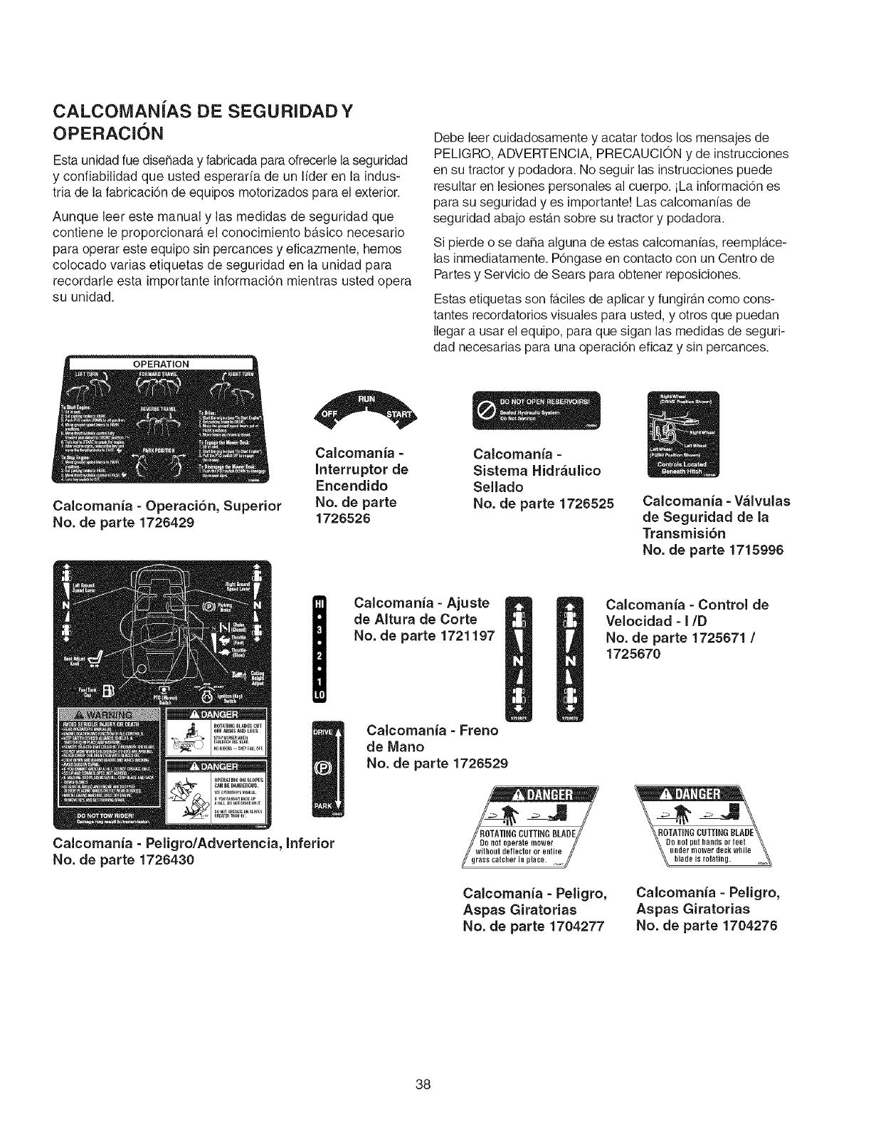
CALCOMANiAS DE SEGURIDADY
OPERACION
Esta unidadfue diseSaday fabricada paraofrecerle laseguridad
y confiabilidad que usted esperarfa de un Nder en la indus-
tria de la fabricacidn de equipos motorizados para el exterior.
Aunque leer este manual y las medidas de seguridad que
contiene le proporcionara, el conocimiento ba.sico necesario
para operar este equipo sin percances y eficazmente, hemos
colocado varias etiquetas de seguridad en la unidad para
recordarle esta importante informacidn mientras usted opera
su unidad.
OPERATION
Calcomania - Operaci6n, Superior
No. de parte 1726429
Calcomania -
Interruptor de
Encendido
No. de parte
1726526
Debe leer cuidadosamente y acatar todos los mensajes de
PELIGRO, ADVERTENCiA, PRECAUCiON y de instrucciones
en su tractor y podadora. No seguir las instrucciones puede
resultar en lesiones personales al cuerpo, iLa informacidn es
para su seguridad yes importante! Las calcomanfas de
seguridad abajo esta.nsobre su tractor y podadora.
Si pierde o se daSaalguna de estas calcomanias, reempla.ce-
las inmediatamente. POngaseen contacto con un Centro de
Partes y Servicio de Sears para obtener reposiciones.
Estas etiquetas son fa.cilesde aplicar y fungira.ncomo cons-
tantes recordatorios visuales para usted, y otros que puedan
Ilegar a usar el equipo, para que sigan las medidas de seguri-
dad necesarias para una operacidn eficaz y sin percances.
Calcomania -
Sistema Hidr_ulico
Sellado
No. de parte 1726525 Calcomania - V_lvulas
de Seguridad de la
Transmisi6n
No. de parte 1715996
Calcomania -Ajuste
de AItura de Corte
No. de parte 1721197
Calcomania - Control de
Velocidad - i/D
No. de parte 1725671 /
1725670
Calcomania - Peligro/Advertencia, Inferior
No. de parte 1726430
Calcomania -Freno
de Mano
No. de parte 1726529
FIOTATING CUTTING BLADE//
0not 01leYate mower //
witfi0utdeflectoror entire
/ss catcher inplace. ,_:
Calcomanfa - Peligro,
Aspas Giratorias
No. de parte 1704277
Calcomanfa - Peligro,
Aspas Giratorias
No. de parte 1704276
38
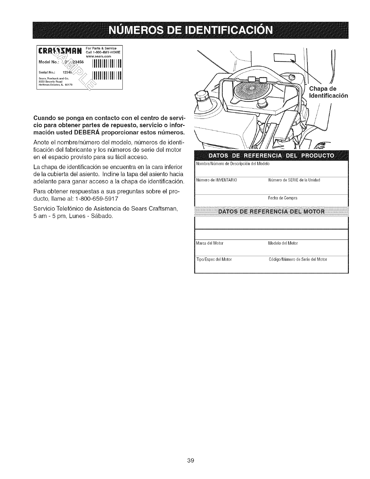
IIIlillllllllll
Iliiillililllil
\
Chapa de
Identificaci6n
Cuando se ponga en contacto con el centro de servi-
cio para obtener partes de repuesto, servicio o infor=
maci6n usted DEBERA proporcionar estos nemeros.
Anote el nombre/n_mero del modelo, nQmeros de identi-
ficaci6n del fabricante y los nQmeros de serie del motor
en el espacio provisto para su fb,cil acceso.
La chapa de identificaci6n se encuentra en la cara inferior
de la cubierta del asiento. Incline la tapa del asiento hacia
adelante para ganar acceso a la chapa de identificaci6n.
Para obtener respuestas a sus preguntas sobre el pro-
ducto, Ilame ah 1-800-659-5917
Servicio Telef6nico de Asistencia de Sears Craftsman,
5 am - 5 pm, Lunes - Sgtbado.
Nombre/Numero de Descripci6n del Modelo
N_mero de INVENTARIO Numero de SERIE de la Unidad
Fecha de Compra
Marca del Motor Modelo del Motor
Tipo/Espec del Motor C6digo/N_mero de Serie del Motor
39
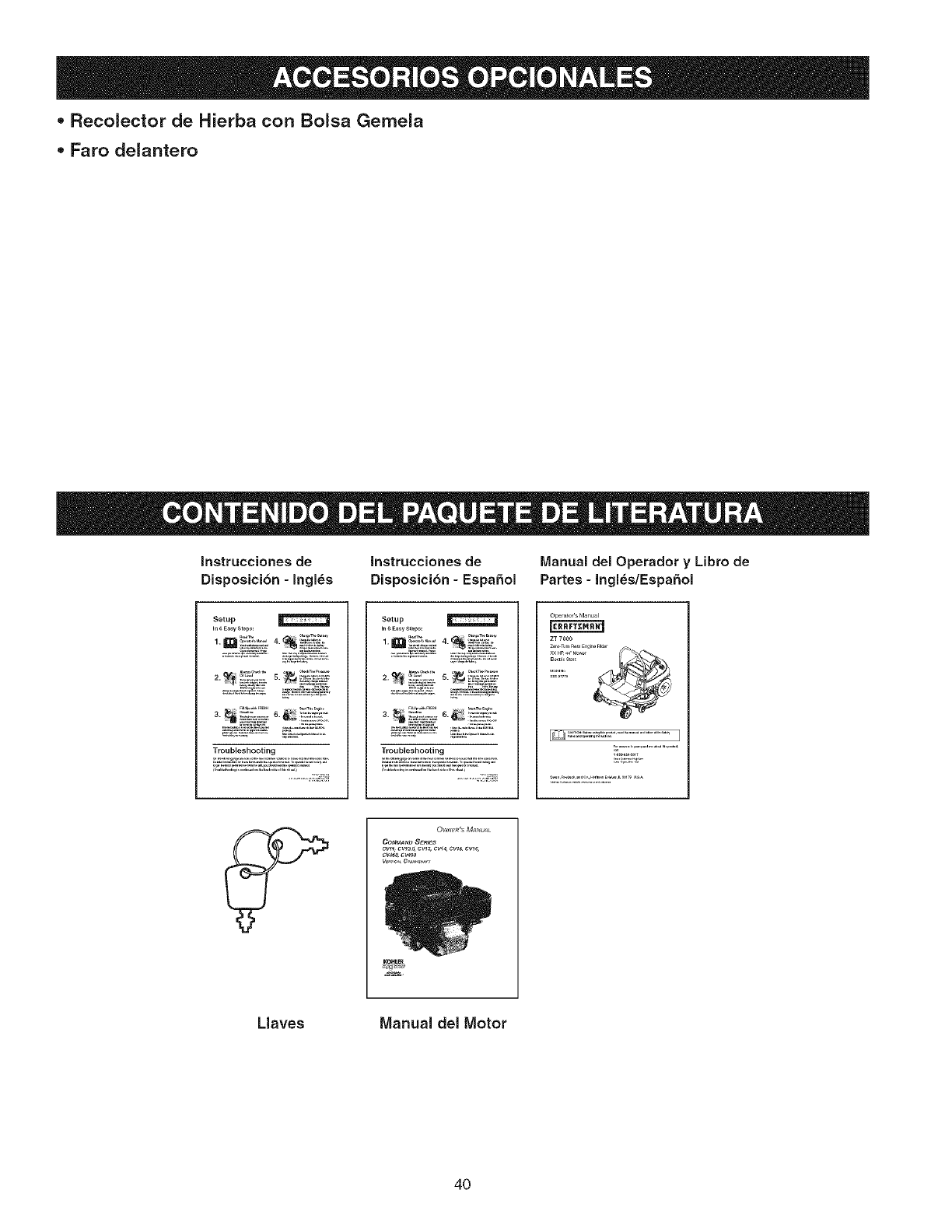
- Recolector de Hierba con Bolsa Gemela
- Faro delantero
Instrucciones de
Disposici6n -Ingles
Instrucciones de IVlanual del Operador y Libro de
Disposici6n -EspaSol Partes - Ingl_s/EspaSol
Setup
in 6 E_y _tep:
Troubleshooting
Setup
......... L_ ,,=__,
2._ _2:_:_s._ _2_)_u_'
Troubleshooting
Oper_toCsManu_l
Z_ 700O
O_l_Wt_'s MANU_L
Cot_t_D SER_S
CW_ C_, _W_, CV_, CW_,CW_,
Llaves Manual del Motor
4O
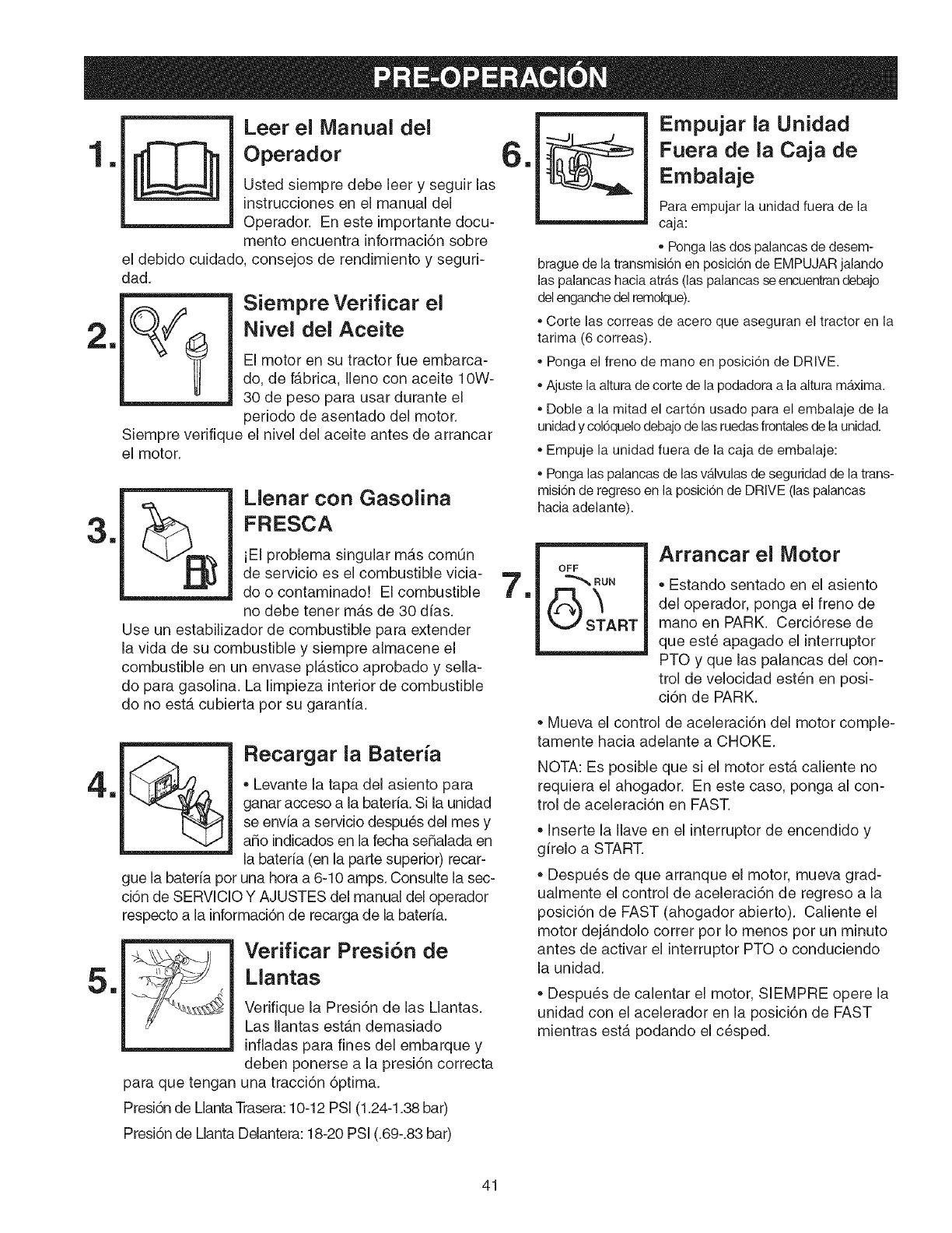
I!
1
m
11
11
mLeer el Manual del
Operador
Usted siempre debe leer y seguir las
instrucciones en el manual del
Operador. En este importante docu-
mento encuentra informaci6n sobre
el debido cuidado, consejos de rendimiento y seguri-
dad.
Siempre verifique
el motor.
Siempre Verificar el
Nivel del Aceite
El motor en su tractor fue embarca-
do, de fabrica, Ileno con aceite 10W-
30 de peso para usar durante el
periodo de asentado del motor.
el nivel del aceite antes de arrancar
Llenar con Gasolina
FRESCA
iEI problema singular mgts comQn
de servicio es el combustible vicia-
do o contaminado! El combustible
no debe tenet mgts de 30 dias.
Use un estabilizador de combustible para extender
la vida de su combustible y siempre almacene el
combustible en un envase plastico aprobado y sella-
do para gasolina. La iimpieza interior de combustible
do no estgt cubierta pot su garantia.
%Recargar ia Bateria
Levante la tapa del asiento para
ganar acceso a la baterfa. Si la unidad
se envia a servicio despu6s del mes y
aho indicados en la fecha sehalada en
la bateria (en la parte superior) recar-
gue la bateria pot una hora a 6-10 amps. Consulte ia sec-
ci6n de SERViCiO Y AJUSTES del manual del operador
respecto a la informaci6n de recarga de la bateria.
para que tengan
Verificar Presi6n de
Mantas
Verifique la Presi6n de las Llantas.
Las Ilantas estgtn demasiado
infladas para fines dei embarque y
deben ponerse a la presi6n correcta
una tracci6n 6ptima.
11
11
Empujar la Unidad
Fuera de la Caja de
Embalaje
Para empujar la unidad fuera de la
caja:
,,Pongalas dos palancasde desem-
brague de la transmisi6n en posici6n de EMPUJAR jalando
las palancas hacia atrAs (las palancas se encuentrandebajo
del enganche del remolque).
,, Corte las correas de acero que aseguran el tractor en la
tarima (6 correas).
,, Ponga el freno de mano en posici6n de DRIVE.
,,Ajuste la altura de corte de la podadora a la altura m_xima.
,, Doble a la mitad el cart6n usado para el embalaje de la
unidad y col6quelo debajo de las ruedas frontales de la unidad.
,, Empuje la unidad fuera de la caja de embalaje:
,, Ponga las palancas de las vAIvulas de seguridad de la trans-
misi6n de regreso en la posici6n de DRIVE (las palancas
hacia adelante).
OFF
RUN
START
Arrancar el Motor
Estando sentado en el asiento
del operador, ponga el freno de
mano en PARK. Cerci6rese de
que est6 apagado el interruptor
PTO y que las palancas del con-
trol de velocidad est6n en posi-
ci6n de PARK.
Mueva el control de aceleraci6n del motor comple-
tamente hacia adelante a CHOKE.
NOTA: Es posible que si el motor esta caliente no
requiera el ahogador. En este caso, ponga al con-
trol de aceleraci6n en FAST.
Inserte la Ilave en el interruptor de encendido y
girelo a START.
Despu6s de que arranque el motor, mueva grad-
ualmente el control de aceleraci6n de regreso a la
posici6n de FAST (ahogador abierto). Caliente el
motor dejgtndolo cotter pot Io menos pot un minuto
antes de activar el interruptor PTO o conduciendo
la unidad.
Despues de calentar el motor, SlEMPRE opere la
unidad con el acelerador en la posici6n de FAST
mientras esta podando el c6sped.
Presi6n de MantaTrasera: 10-12 PSI (1.24-1.38 bar)
Presi6n de Manta Delantera: 18-20 PSI (.69-.83 bar)
41
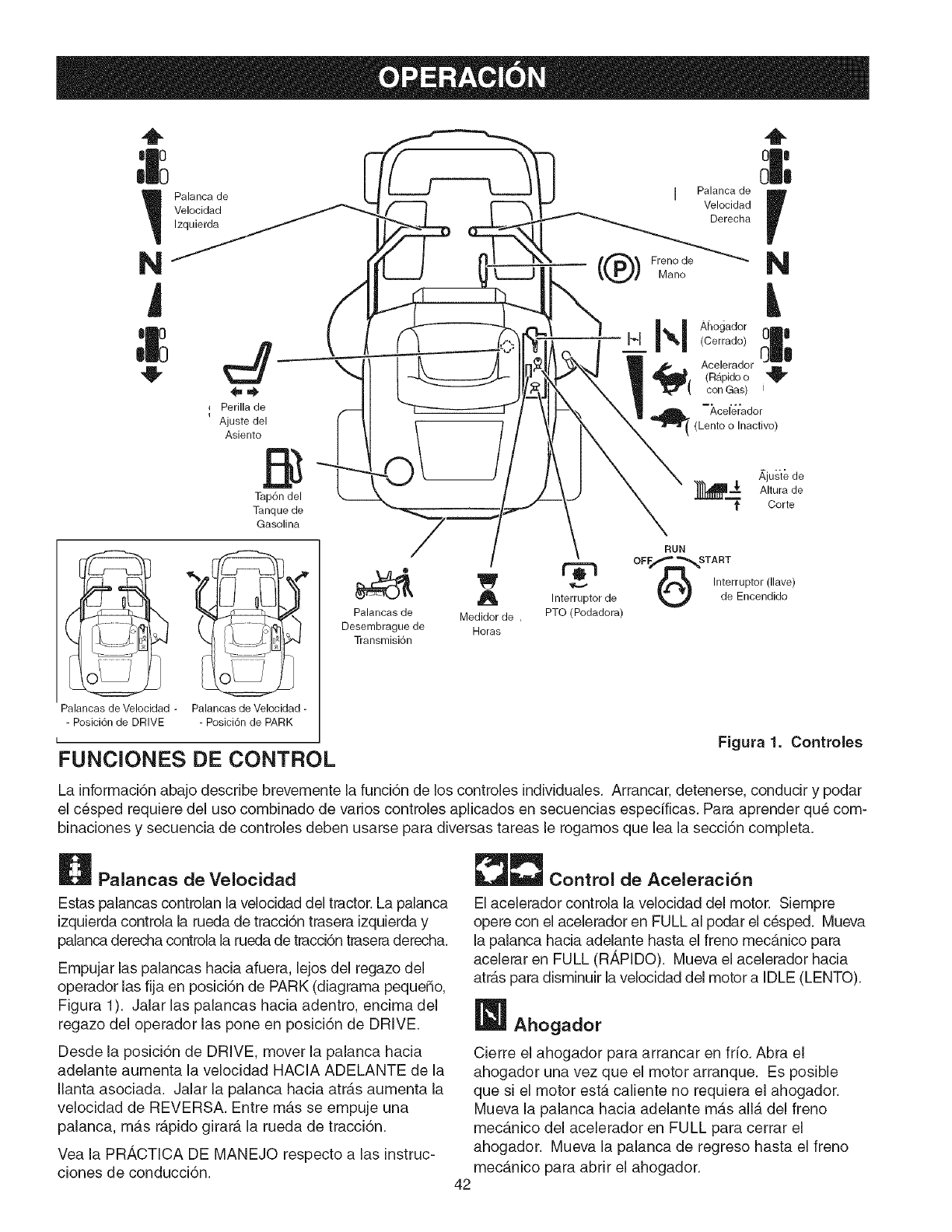
!_ Palanca de I Palanca de
Velocidad Velocidad
Izquierda Derecha
N Freno de
Mano
W
Perilla de
iAjuste del
Asiento B
Tapdn del
Tanque de
Gaeolina
N
I,_1_ I AhogadorI_1 (Cerrado)
_( Acelerador
(Rapido o "_
con Gas) t
Acelerador
( (Lento o Inactivo)
_,juste de
_ Altura de
t Corte
Palancas de Velocidad -Palancas de Velocidad -
- Posici6n de DRIVE - Posici6n de PARK
I
FUNClONES DE CONTROL
RUN
OFF_ _STA RT
/.t"_% Interrupto_(,_ve)
:= ,n,erro";or o
Palancae de Medidor de , PTO (Podadora)
Desernbrague de Horas
Transrnisi6n
Figura 1. Controles
La informaci6n abajo describe brevemente la funci6n de los controles individuales. Arrancar, detenerse, conducir y podar
el c6sped requiere del uso combinado de vafios controles aplicados en secuencias especificas. Para aprender qu6 com-
binaciones y secuencia de controles deben usarse para diversas tareas le rogamos que lea la secci6n completa.
Palancas de Velocidad
Estas palancas controlan la velocidad del tractor. La palanca
izquierda controla la rueda de tracci6n trasera izquierda y
palanca derecha controla la rueda de tracci6n trasera derecha.
Empujar las palancas hacia afuera, lejos del regazo del
operador las fija en posici6n de PARK (diagrama pequefio,
Figura 1). Jalar las palancas hacia adentro, encima del
regazo del operador las pone en posici6n de DRIVE.
Desde la posici6n de DRIVE, mover la palanca hacia
adelante aumenta la velocidad HACIA ADELANTE de la
Ilanta asociada. Jalar la palanca hacia atr_.s aumenta la
velocidad de REVERSA. Entre mb,s se empuje una
palanca, mas rapido girard, la rueda de tracci6n.
Vea la PRt,,CTICA DE MANEJO respecto a las instruc-
ciones de conducci6n.
_L_ Control de Aceleraci6n
El acelerador controla la velocidad del motor. Siempre
opere con el acelerador en FULL al podar el c6sped. Mueva
la palanca hacia adelante hasta el freno mecanico para
acelerar en FULL (RAPIDO). Mueva el acelerador hacia
atras para disminuir la velocidad del motor a IDLE (LENTO).
42
Ahogador
Cierre el ahogador para arrancar en frio. Abra el
ahogador una vez que el motor arranque. Es posible
que si el motor esta caliente no requiera el ahogador.
Mueva la palanca hacia adelante mb,s alia del freno
mecb,nico del acelerador en FULL para cerrar el
ahogador. Mueva la palanca de regreso hasta el freno
mecanico para abrir el ahogador.
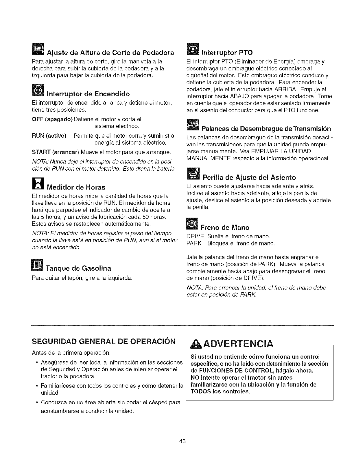
Ajuste de AJtura de Corte de Podadora
Para ajustar la altura de corte, gire la manivela a la
derecha para subir la cubierta de la podadora y a la
izquierda para bajar la cubierta de la podadora.
Interrupter de Encendido
El interrupter de encendido arranca y detiene el motor;
tiene tres posiciones:
OFF (apagado) Detiene el motor y corta el
sistema el6ctrico.
RUN (active) Permite que el motor corra y suministra
energia al sistema electrico.
START (arrancar) Mueve el motor para que arranque.
NOTA: Nunca deje el interrupter de encendido en la posi-
cidn de RUN con el motor detenido. Esto drena la baterfa.
B Medidor de Horas
El medidor de horas mide la cantJdad de horas que la
Ilave Ileva en la posici6n de RUN. El medidor de horas
har_. que parpadee el indicador de cambio de aceite a
las 5 horas, y un aviso de lubrJcaci6n cada 50 horas.
Estos avisos se restablecen automaticamente.
NOTA: El medidor de horas registra e/paso de/tiempo
cuande la /lave esta en posicidn de RUN, aun si el motor
no esta encendido.
Tanque de Gasolina
Para quitar el tap6n, gire a la izquierda.
_ Interrupter PTO
El interrupter PTO (Eliminador de Energia) embraga y
desembraga un embrague el6ctrico conectado al
cig0e_al del motor. Este embrague electrico conduce y
detJene la cubierta de la podadora. Para encender la
podadora, jale el interrupter hacia ARRJBA. Empuje el
interrupter hacia ABAJO para apagar la podadora. Tome
en cuenta que el operador debe estar sentado firmemente
en el asiento del conductor para que el PTO funcione.
Palancas de Desembrague de Transmisi6n
Las palancas de desembrague de la transmisi6n desacti-
van las transmisiones para que la unidad pueda empu-
jarse manualmente. Vea EMPUJAR LA UNiDAD
MANUALMENTE respecto a la informaci6n operacional.
Perilla de Ajuste del Asiento
El asiento puede ajustarse hacJa adelante y atr_.s.
incline el asiento hacia adelante, afioje la perilla de
ajuste, desiice el asiento a la posici6n deseada y apriete
la perilla.
Freno de Mane
DRIVE Suelta el freno de mane.
PARK BIoquea el freno de mane.
Jale la palanca del freno de mane hasta engranar el
freno de mane (posici6n de PARK). Mueva la palanca
completamente hacia abajo para desengranar el freno
de mane (posici6n de DRIVE).
NOTA: Para arrancar la unidad, el freno de mane debe
estar en posicidn de PARK.
SEGURIDAD GENERAL DE OPERACION
Antes de la primera operaci6n:
• AsegQrese de leer toda la informaci6n en las secciones
de Seguridad y Operaci6n antes de intentar operar el
tractor o la podadora.
Familiaricese con todos los controles y c6mo detener la
unidad.
• Conduzca en un _.rea abierta sin podar el c6sped para
acostumbrarse a conducir la unidad.
ADVERTENCIA
Si usted no entJende c6mo funcJona un control
especffico, ono ha leido con detenimiento la secci6n
de FUNClONES DE CONTROL, h&galo ahora.
NO Jntente operar el tractor sin antes
familiadzarse con la ubJcaci6n y la funci6n de
TODOS los controles.
43
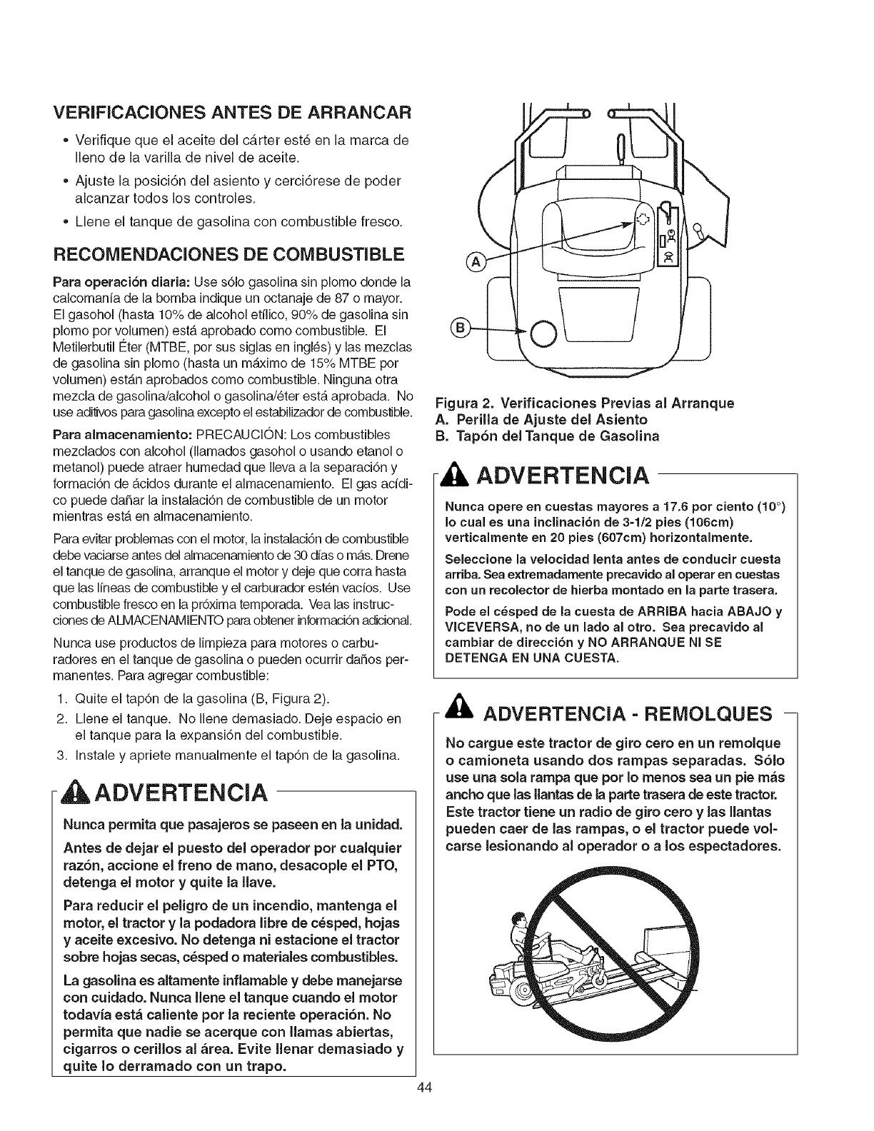
VERIFICACIONES ANTES DE ARRANCAR
• Verifique que el aceite del cb,rter est6 en la marca de
Ileno de la varilla de nivel de aceite.
• Ajuste la posici6n del asiento y cerci6rese de poder
alcanzar todos los controles.
• Llene el tanque de gasolina con combustible fresco.
RECOMENDACIONES DE COMBUSTIBLE
Para operaciSn diaria: Use s61o gasolina sin plomo donde la
calcomania de la bomba indique un octanaje de 87 o mayor.
El gasohol (hasta 10% de alcohol etflico, 90% de gasolina sin
plomo pot volumen) estb, aprobado como combustible. El
Metilerbutil Eter (MTBE, pot sus siglas en ingles) y las mezclas
de gasolina sin plomo (hasta un mAximo de 15% MTBE pot
volumen) estb,n aprobados como combustible. Ninguna otra
mezcla de gasolina/alcohol o gasolina/6ter estb, aprobada. No
use aditivos para gasolina excepto el estabilizador de combustible.
Para almacenamiento: PRECAUCION: Los combustibles
mezclados con alcohol (llamados gasohol o usando etanol o
metanol) puede atraer humedad que Ileva a la separaci6n y
formaciOn de _.cidos durante el almacenamiento. El gas acidi-
co puede daSar la instalaciOn de combustible de un motor
mientras estb, en almacenamiento.
Paraevitarproblemascon el motor,la instalaci6nde combustible
debevaciarseantesdelalmacenamientode 30 d{aso mb,s.Drene
el tanque de gasolina,arranque el motor y deje que corra hasta
que las Ifneasde combustible y el carburadorest_n vacios. Use
combustiblefresco en la prOximatemporada. Vea las instruc-
clonesde ALMACENAMIENTOparaobtenerinformaciOnadicional.
Nunca use productos de limpieza para motores o carbu-
radores en el tanque de gasolina o pueden ocurrir daSos per-
manentes. Para agregar combustible:
1. Quite el tapOn de la gasolina (B, Figura 2).
2. Llene el tanque. No Ilene demasiado. Deje espacio en
el tanque para la expansi6n del combustible.
3. Instale y apriete manualmente el tapOn de la gasolina.
ADVERTENCIA
Nunca permita que pasajeros se paseen en la unidad.
Antes de dejar el puesto del operador pot cualquier
raz6n, accione el freno de mano, desacople el PTO,
detenga el motor y quite la Ilave.
Para reducir el peligro de un incendio, mantenga el
motor, el tractor y la podadora libre de c_sped, hojas
yaceite excesivo. No detenga ni estacione el tractor
sobre hojas secas, c_sped o materiales combustibles.
La gasolina es altamente inflamable y debe manejarse
con cuidado. Nunca Ilene el tanque cuando el motor
todavia est& caliente pot la reciente operaci6n. No
permita que nadie se acerque con llamas abiertas,
cigarros o cerillos al &tea. Evite llenar demasiado y
quite Io derramado con un trapo.
44
Figura 2. Verificaciones Previas al Arranque
A. Perilla de Ajuste del Asiento
B. Tap6n del Tanque de Gasolina
ADVERTENCIA
Nunca opere en cuestas mayores a 17.6 pot ciento (10 °)
Io cual es una inclinaci6n de 3-1/2 pies (106cm)
verticalmente en 20 pies (607cm) horizontalmente.
Seleccione la velocidad lenta antes de conducir cuesta
arriba. Sea extremadamente precavido al operar en cuestas
con un recolector de hierba montado en la parte trasera.
Pode el cesped de la cuesta de ARRIBA hacia ABAJO y
VICEVERSA, no de un lado al otto. Sea precavido al
cambiar de direccibn y NO ARRANQUE NI SE
DETENGA EN UNA CUESTA.
ADVERTENCIA- REIVIOLQUES -
No cargue este tractor de giro cero en un remolque
o camioneta usando dos rampas separadas. S61o
use una sola tampa que pot Io menos sea un pie m_s
ancho que las llantas de la parte trasera de este tractor.
Este tractor tiene un radio de giro cero y las Ilantas
pueden caer de las rampas, o el tractor puede vol-
carse lesionando al operador oalos espectadores.
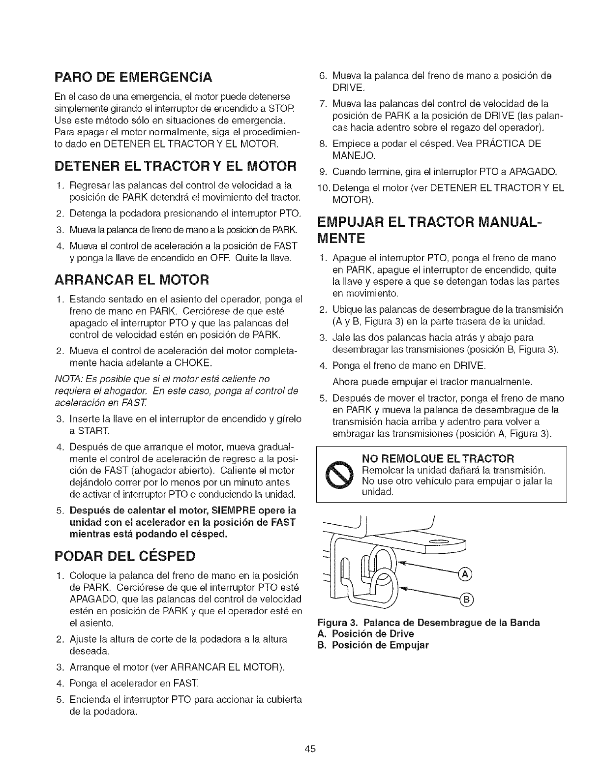
PARO DE EMERGENCIA
En el caso de una emergencia, el motor puede detenerse
simplemente girando el interruptor de encendido a STOR
Use este metodo s61o en situaciones de emergencia.
Para apagar el motor normalmente, sJga el procedimien-
to dado en DETENER EL TRACTOR Y EL MOTOR.
DETENER EL TRACTOR Y EL MOTOR
1. Regresar las palancas del control de velocidad a la
posici6n de PARK detendra el movimiento del tractor.
2. Detenga la podadora presionando el interruptor PTO.
3. Muevala palanca de frenode mano a la I:_sici6nde PARK.
4. Mueva el control de aceleraci6n a la posici6n de FAST
y ponga la Ilave de encendido en OFR Quite la Ilave.
ARRANCAR EL MOTOR
1. Estando sentado en el asiento del operador, ponga el
freno de mano en PARK. Cerci6rese de que est_
apagado el interruptor PTO y que las palancas del
control de velocidad est6n en posici6n de PARK.
2. Mueva el control de aceleraci6n del motor completa-
mente hacia adelante a CHOKE.
NOTA: Es posible que si el motor esta caliente no
requiera el ahogador, En este caso, ponga al control de
aceleracidn en FAST.
3. Inserte la Ilave en el interruptor de encendido y girelo
a START.
4. Despu6s de que arranque el motor, mueva gradual-
mente el control de aceleraci6n de regreso a la posi-
ci6n de FAST (ahogador abierto). Caliente el motor
dejb,ndolo cotter por Io menos por un minuto antes
de activar el interruptor PTO o conduciendo la unidad.
5. Despu_s de calentar el motor, SIEMPRE opere la
unidad con el acelerador en la posici6n de FAST
mientras est& podando el c_sped.
PODAR DEL CO:SPED
1. Coloque la palanca del freno de mano en la posici6n
de PARK. Cerci6rese de que el interruptor PTO est6
APAGADO, que las palancas del control de velocidad
est6n en posici6n de PARK y que el operador est6 en
el asiento.
2. Ajuste la altura de corte de la podadora a la altura
deseada.
3. Arranque el motor (ver ARRANCAR EL MOTOR).
4. Ponga el acelerador en FAST.
5. Encienda el interruptor PTO para accionar la cubierta
de la podadora.
6.
7.
8.
Mueva la palanca del freno de mano a posici6n de
DRIVE.
Mueva las palancas del control de velocidad de la
posici6n de PARK a la posici6n de DRIVE (las palan-
cas hacia adentro sobre el regazo del operador).
Empiece a podar el c6sped. Vea PR/_,CTICA DE
MANEJO.
9. Cuando termine, gJra el interruptor PTO a APAGADO.
10. Detenga el motor (vet DETENER EL TRACTOR Y EL
MOTOR).
EMPUJAR EL TRACTOR MANUAL-
MENTE
Apague el interruptor PTO, ponga el freno de mano
en PARK, apague el interruptor de encendido, quite
la Ilave y espere a que se detengan todas las partes
en movimiento.
2. Ubique las palancas de desembrague de la transmisi6n
(A y B, Figura 3) en la parte trasera de la unidad.
3. Jale las dos palancas hacia atras y abajo para
desembragar las transmisiones (posici6n B, Figura 3).
4. Ponga el freno de mano en DRIVE.
Ahora puede empujar el tractor manualmente.
5. Despu6s de mover el tractor, ponga el freno de mano
en PARK y mueva la palanca de desembrague de la
transmisi6n hacia arriba y adentro para volver a
embragar las transmisiones (posici6n A, Figura 3).
NO REIVlOLQUE EL TRACTOR
Remolcar la unidad da_ara la transmisi6n.
No use otto vehiculo para empujar o jalar la
unidad.
Figura 3. Palanca de Desembrague de la Banda
A. Posici6n de Drive
B. Posici6n de Empujar
45
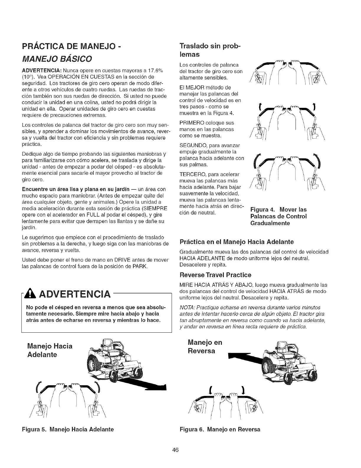
PR. ,CTICA DE IVIANEJO -
MANEJO BASlCO
ADVERTENClA: Nunca opere en cuestas mayoras a 17.6%
(10°). Vea OPERACION EN CUESTAS en la secci6n de
seguridad. Los tractores de giro cero operan de modo difer-
ente a otros vehiculos de cuatro ruedas. Las ruedas de trac-
ci6n tambien son sus ruedas de direcci6n. Si usted no puede
conducir la unidad en una colina, usted no podra dirigir la
unidad en ella. Operar unidades de giro cero en cuestas
requiere de precauciones extremas.
Los controles de palanca del tractor de giro cero son muy sen-
sibles, y aprender a dominar los movimientos de avance, rever-
say vuelta del tractor con eficiencia y sin problemas requiere
prActica.
Dedique algo de tiempo probando las siguientes maniobras y
para familiarizarse con como acelera, se traslada y dirige la
unidad - antes de empezar a podar del cesped - es absoluta-
mente esencial para sacarle el mayor provecho al tractor de
giro cero.
Encuentre un Area lisa y plana en su jardin -- un Area con
mucho espacio para maniobrar. (Antes de empezar quite del
Area cualquier objeto, gente y animales.) Opere la unidad a
media aceleraci6n durante esta sesi6n de practica (SIEMPRE
opere con el acelerador en FULL al podar el cesped), y gire
lentamente para evitar que derrapen las Ilantas y se dade su
jardin.
Le sugerimos que empiece con el procedimiento de traslado
sin problemas a la derecha, y luego siga con las maniobras de
avance, reversa y vuelta.
Usted debe porter el freno de mano en DRIVE antes de mover
las palancas de control fuera de la posici6n de PARK.
ADVERTENCIA
No pode el c6sped en reverea a menos que sea absolu-
tamente necesario, Siempre mire hacia abajo y hacia
atrAs antes de echarse en reversa y mientras Io hace.
Manejo Hacia
Adelante
Traslado sin prob=
lemas
Los controles de palanca
del tractor de giro cero son
altamente sensibles.
El MEJOR metodo de
manejar las palancas del
control de velocidad es en
tres pasos - como se
muestra en la Figura 4.
PRIMERO coloque sus
manos en las palancas
como se muestra.
SEGUNDO, para avanzar
empuje gradualmente la
palanca hacia adelante con
sus palmas.
TERCERO, para acelerar
mueva las palancas mas
hacia adelante. Para bajar
suavemente la velocidad,
mueva las palancas lenta-
mente hacia atras en direc-
ci6n de neutral. Figura 4. Mover las
Palancas de Control
Gradualmente
Practica en el IVlanejo Hacia Adelante
Gradualmente mueva las dos palancas del control de velocidad
HACIA ADELANTE de modo uniforme lejos del neutral.
Desacelere y repita.
Reverse Travel Practice
MIRE HACIA ATRAS Y ABAJO, luego mueva gradualmente las
dos palancas del control de velocidad HACIA ATRAS de modo
uniforme lejos del neutral. Desacelere y repita.
NOTA: Practique echarse en reversa durante varios minutos
antes de intentar hacerlo cerca de algdn objeto. El tractor gira
tan abruptamente en reversa como cuando va hacia adelante,
y andar en reversa en Ifnea recta requiere de prbctica.
Manejo en
Reversa
Figura 5. Manejo Hacia Adelante Figura 6. Manejo en Reversa
46
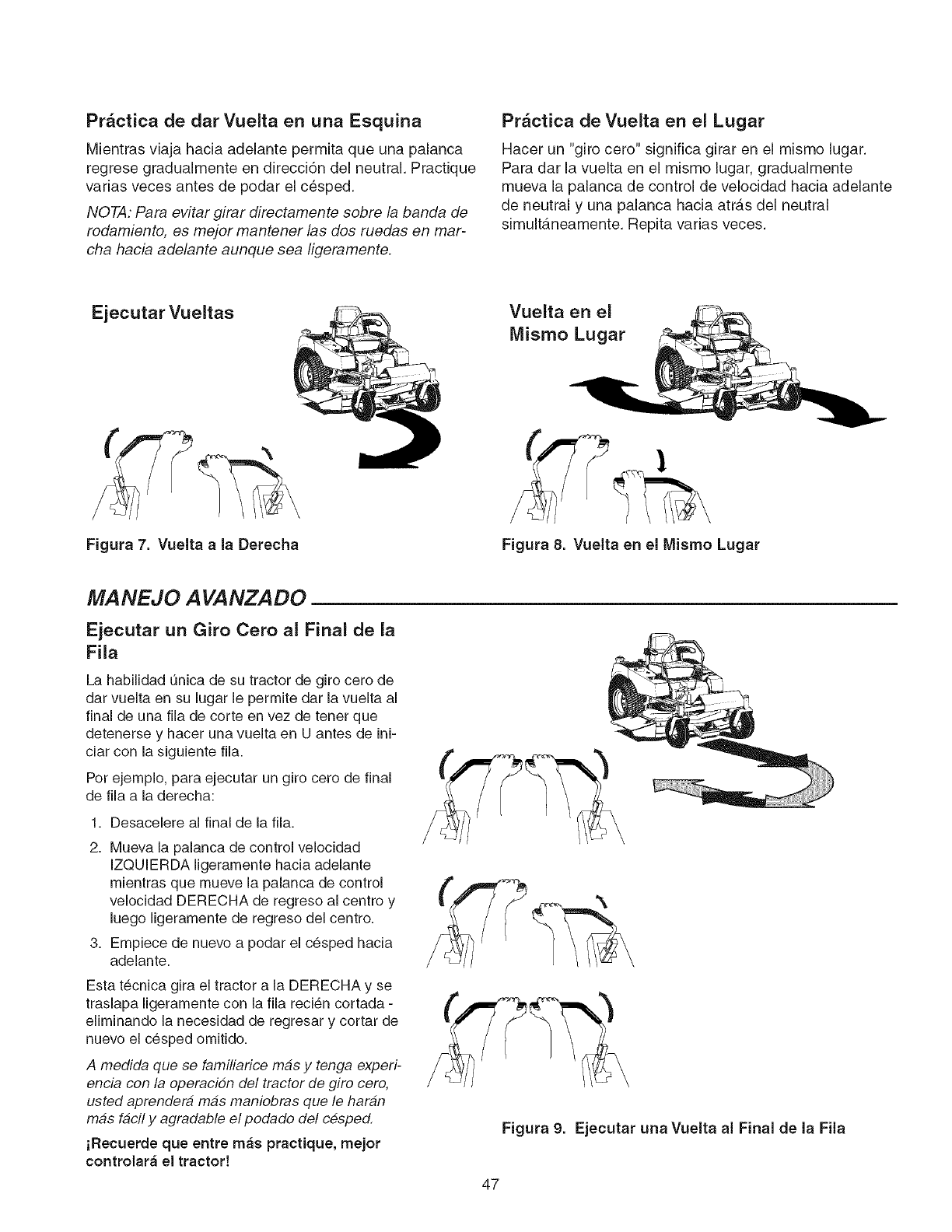
Prbctica de dar Vuelta en una Esquina
Mientras viaja hacia adelante permita que una palanca
regrese gradualmente en direcci6n del neutral. Practique
varias veces antes de podar el cesped.
NOTA: Para evitar girar directamente sobre la banda de
rodamiento, es mejor mantener /as dos ruedas en mar-
cha hacia adelante aunque sea ligeramente.
Pr_ctica de Vuelta en el Lugar
Hacer un "giro cero" significa girar en el mismo lugar.
Para dar ia vuelta en ei mismo lugar, gradualmente
mueva la palanca de control de velocidad hacia adelante
de neutral y una palanca hacia atrAs del neutral
simult_.neamente. Repita varias veces.
Ejecutar Vueltas Vuelta en el
Mismo Lugar
Figura 7. Vuelta a la Derecha Figura 8. Vuelta en el Mismo Lugar
MANEJO A VANZADO
Ejecutar un Giro Cero al Final de la
Fila
La habilidad unica de su tractor de giro cero de
dar vuelta en su lugar le permite dar la vuelta al
final de una fila de corte en vez de tenet que
detenerse y hacer una vuelta en U antes de ini-
ciar con la siguiente fila.
Pot ejemplo, para ejecutar un giro cero de final
de fila a la derecha:
1. Desacelere al final de la fila.
2. Mueva la palanca de control velocidad
IZQUIERDA ligeramente hacia adelante
mientras que mueve la palanca de control
velocidad DERECHA de regreso al centro y
luego ligeramente de regreso del centro.
3. Empiece de nuevo a podar el c_sped hacia
adelante.
Esta t_cnica gira el tractor a la DERECHA y se
traslapa ligeramente con la fila reci6n cortada -
eliminando la necesidad de regresar y cortar de
nuevo el c_sped omitido.
A medida que se familiarice mas y tenga experi-
encia con la operacion del tractor de giro cero,
usted aprendera mas maniobras que le haran
mas facil y agradable el podado del cesped.
iRecuerde que entre m_s practique, mejor
controlar_ el tractor!
Figura 9. Ejecutar una Vuelta al Final de la Fila
47
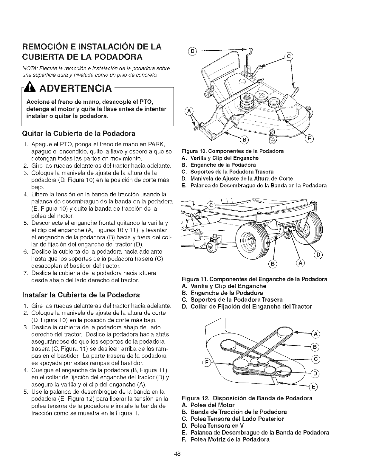
REMOCION E INSTALACION DE LA
CUBIERTA DE LA PODADORA
NOTA:Ejecute la remocidn e instalacidn de la podadora sobre
una supefficie dura y nivelada como unpiso de concreto.
ADVERTENCIA
Accione el freno de mano, desacople el PTO,
detenga el motor y quite la llave antes de intentar
instalar o quitar la podadora.
Quitar la Cubierta de la Podadora
1. Apague el PTO, ponga el freno de mano en PARK,
apague el encendido, quite la Ilave y espere a que se
detengan todas las partes en movimiento.
2. Gire las ruedas delanteras del tractor hacia adelante.
3. Coloque la manivela de ajuste de la altura de la
podadora (D, Figura 10) en la posici6n de corte m_.s
bajo.
4. Libere la tensi6n en la banda de tracci6n usando la
palanca de desembrague de la banda en la podadora
(E, Figura 10) y quite la banda de tracci6n de la
polea del motor.
5. Desconecte el enganche frontal quitando la varilla y
el clip del enganche (A, Figuras 10 y 11), y levantar
el enganche de la podadora (B) hacia y fuera del col-
lar de fijaci6n del enganche del tractor (D).
6. Deslice la cubierta de la podadora hacia adelante
hasta que los soportes de la podadora trasera (C)
desacoplen el bastidor del tractor.
7. Deslice la cubierta de la podadora hacia afuera
desde abajo del lado derecho del tractor.
Instalar la Cubierta de la Podadora
1. Gire las ruedas delanteras del tractor hacia adelante.
2. Coloque la manivela de ajuste de la altura de corte
(D, Figura 10) en la posici6n de corte mb,s bajo.
3. Deslice la cubierta de la podadora abajo del lado
derecho del tractor. Deslice la podadora hacia atr_,s
asegur_.ndose de que los soportes de la podadora
trasera (C, Figura 11) se deslicen arriba de las ram-
pas en el bastidor. La parte trasera de la podadora
es apoyada pot estas rampas del bastidor.
4. Cuelgue el enganche de la podadora (B, Figura 11)
en el collar de fijaci6n del enganche del tractor (D) y
asegure la varilla y el clip del enganche (A).
5. Use la palanca de desembrague de la banda en la
podadora (E, Figura 12) para liberar la tensi6n en la
polea tensora de la podadora e instale la banda de
tracci6n como se muestra en la Figura 1.
Figura 10. Componentes de la Podadora
A. Varilla yClip del Enganche
B. Enganche de la Podadora
C. Soportes de la PodadoraTrasera
D. Manivela de Ajuste de la Altura de Corte
E. Palanca de Desembrague de la Banda en la Podadora
Figura 11. Componentes del Enganche de la Podadora
A. Varilla y Clip del Enganche
B. Enganche de la Podadora
C. Soportes de la Podadora Trasera
D. Collar de Fijaci6n del Enganche del Tractor
Figura 12. Disposici6n de Banda de Podadora
A. Polea del Motor
B. Banda deTracci6n de la Podadora
C. Polea Tensora del Lado Posterior
D. Polea Tensora en V
E. Palanca de Desembrague de la Banda de Podadora
F. Polea Motriz de la Podadora
48
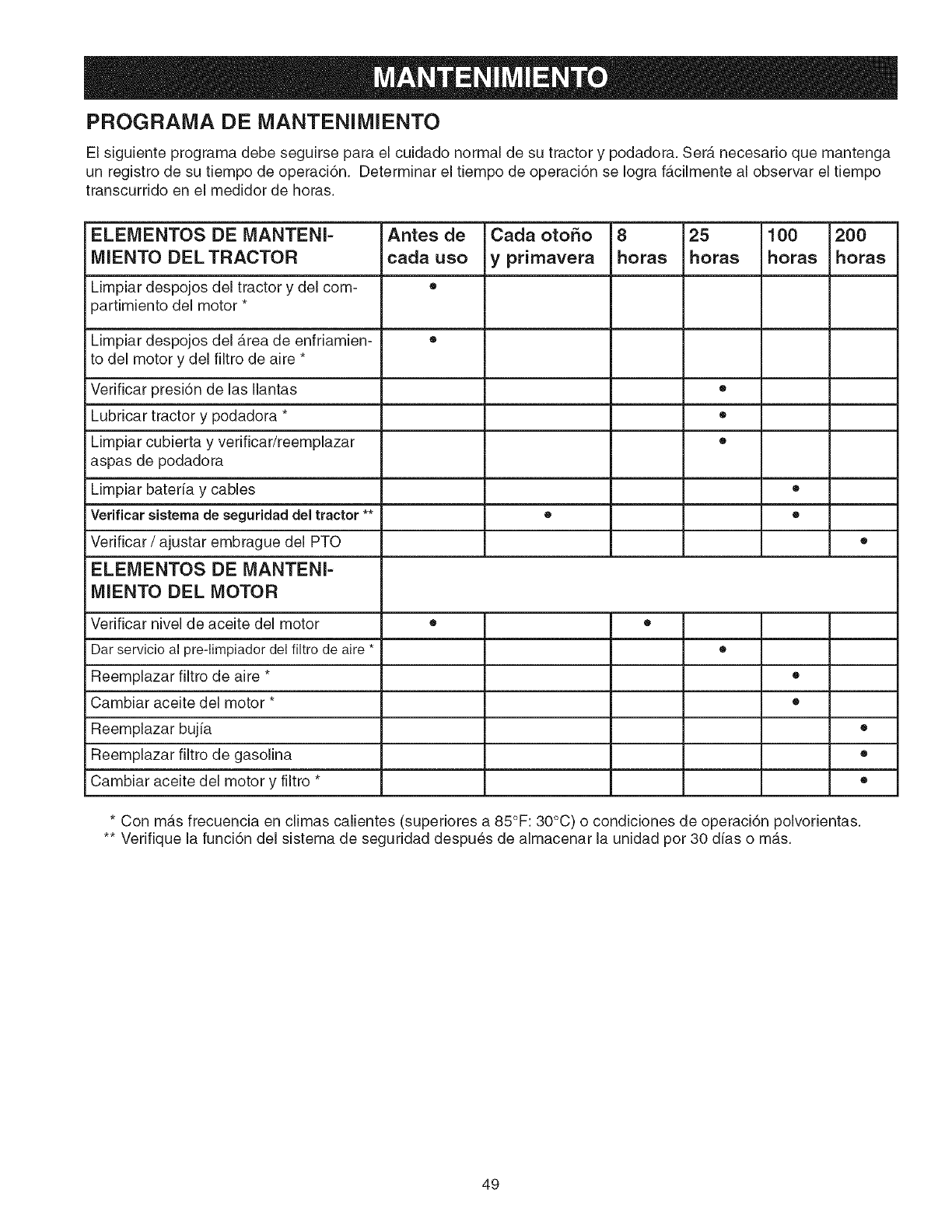
PROGRAIVIA DE MANTENllVilENTO
El siguiente programa debe seguirse para el cuidado normal de su tractor y podadora. Serb, necesario que mantenga
un registro de su tiempo de operaci6n. Determinar el tiempo de operaci6n se Iogra facilmente al observar el tiempo
transcurrido en el medidor de horas.
ELEMENTOS DE MANTENI= Antes de Cada otoSo 8 25 100 200
MIENTO DELTRACTOR cada uso y primavera horas horas horas horas
Limpiar despojos del tractor y del com- •
partimiento del motor *
Limpiar despojos del area de enfriamien- ®
to del motor y del filtro de aire *
Verificar presi6n de las Ilantas •
Lubricar tractor y podadora * ®
Limpiar cubierta y verificar/reemplazar •
aspas de podadora
Limpiar bateria y cables ®
Verificar sistema de seguridaddel tractor ** • •
Verificar /ajustar embrague del PTO •
ELEMENTOS DE MANTENI-
MIENTO DEL MOTOR
Verificar nivel de aceite del motor • •
Dar servicio al pre-limpiador del filtro de aire * ®
Reemplazar filtro de aire * •
Cambiar aceite del motor * •
Reemplazar bujia •
Reemplazar filtro de gasolina •
Cambiar aceite del motor y filtro * ®
* Con mas frecuencia en climas calientes (superiores a 85°F: 30°C) o condiciones de operaci6n polvorientas.
** Verifique la funci6n del sistema de seguridad despu6s de almacenar la unidad pot 30 dias o mas.
49
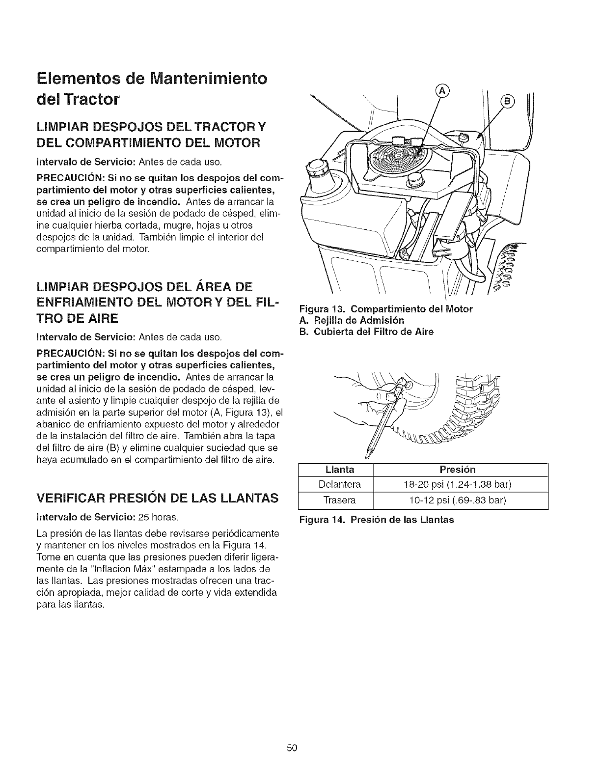
Elementos de Mantenirniento
del Tractor
LIMPIAR DESPOJOS DEL TRACTOR Y
DEL COMPARTIMIENTO DEL MOTOR
Intervalo de Servicio: Antes de cada uso.
PRECAUCION: Si no se quitan los despojos del com-
partimiento del motor y otras superficies calientes,
se crea un peligro de incendio. Antes de arrancar la
unidad al inicio de la sesi6n de podado de c_sped, elim-
ine cualquier hierba cortada, mugre, hojas u otros
despojos de la unidad. Tambien limpie el interior del
compartimiento del motor.
LIMPIAR DESPOJOS DEL AREA DE
ENFRIAMIENTO DEL MOTOR YDEL FIL-
TRO DE AIRE
Intervalo de Servicio: Antes de cada uso.
PRECAUCION: Si no se quitan los despojos del com-
partimiento del motor y otras superficies calientes,
se crea un peligro de incendio. Antes de arrancar la
unidad aJ inicio de la sesi6n de podado de c6sped, lev-
ante el asiento y limpie cualquier despojo de la rejilla de
admisi6n en la parte superior del motor (A, Figura 13), el
abanico de enfrJamiento expuesto del motor y alrededor
de la instalaci6n del filtro de aire. Tambien abra la tapa
deJ filtro de aire (B) y elimine cualquier suciedad que se
haya acumulado en el compartimiento del filtro de aire.
VERIFICAR PRESION DE LAS LLANTAS
Intervalo de Servicio: 25 horas.
La presi6n de las Ilantas debe revisarse peri6dicamente
y mantener en los niveles mostrados en la Figura 14.
Tome en cuenta que las presiones pueden diferir ligera-
mente de la "lnflaci6n Mb,x" estampada a los lados de
las Ilantas. Las presiones mostradas ofrecen una trac-
ci6n apropiada, mejor calidad de corte y vida extendida
para las Ilantas.
Figura 13. Compartimiento deJ Motor
A. Rejilla de Admisi6n
B. Cubierta deJ FiJtro de Aire
Llanta Presi6n
Delantera 18-20 psi (1.24-1.38 bar)
Trasera 10-12 psi (.69-.83 bar)
Figura 14. Presi6n de Jas Llantas
5O
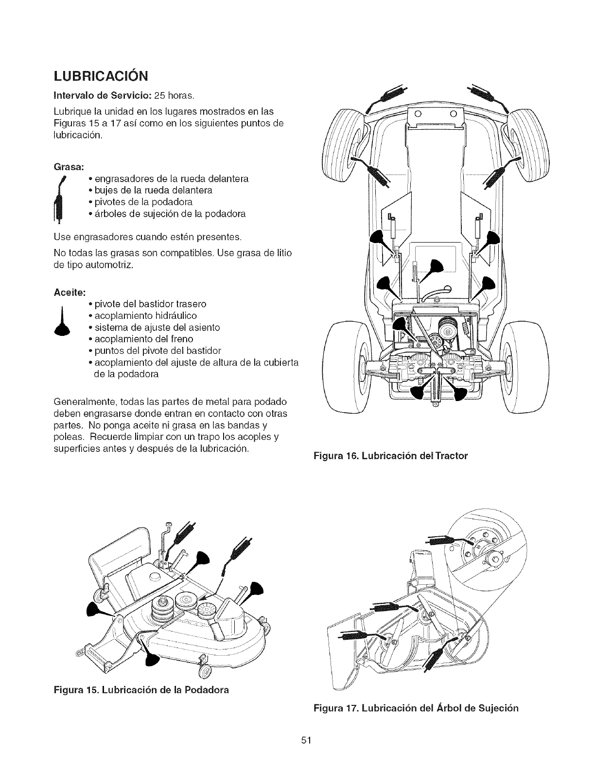
LUBRICACION
Intervalo de Servicio: 25 horas.
Lubrique la unidad en los lugares mostrados en las
Figuras 15 a 17 asi como en los siguientes puntos de
lubricaci6n.
Grasa:
• engrasadores de la rueda delantera
• bujes de la rueda delantera
• pivotes de la podadora
• arboles de sujeci6n de la podadora
Use engrasadores cuando est6n presentes.
No todas las grasas son compatibles. Use grasa de litio
de tipo automotfiz.
Aceite:
• pivote del bastidor trasero
• acoplamiento hidr_.ulico
• sistema de ajuste del asiento
acoplamiento del freno
puntos del pivote del bastidor
acoplamiento del ajuste de altura de la cubierta
de la podadora
Generalmente, todas las partes de metal para podado
deben engrasarse donde entran en contacto con otras
partes. No ponga aceite ni grasa en las bandas y
poleas. Recuerde limpiar con un trapo los acoples y
superficies antes y despues de la lubricaci6n. Figura 16. Lubricaci6n del Tractor
Figura 15. Lubricaci6n de la Podadora
Figura 17. Lubricaci6n del Arbol de Sujeci6n
51
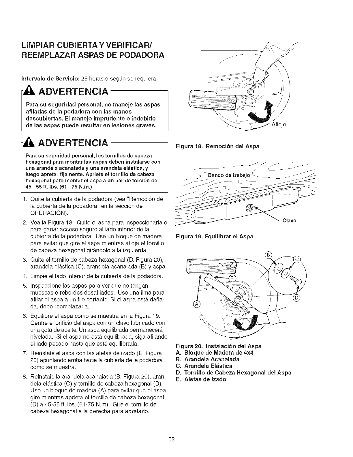
LilVlPIAR CUBIERTAY VERIFICAR/
REEMPLAZAR ASPAS DE PODADORA
Intervalo de Servicio: 25 horas o segQn se requiera.
ADVERTENCIA
Para su seguridad personal, no maneje las aspas
afHadas de la podadora con las manos
descubiertas. El manejo imprudente o indebido
de las aspas puede resuitar en lesiones graves.
ADVERTENCIA
Para su seguridad personal, los tornillos de cabeza
hexagonal para montar las aspas deben instalarse con
una arandela acanalada y una arandela elastica, y
luego apretar fijamente. Apriete el tornillo de cabeza
hexagonal para montar el aspa a un par de torsi6n de
45 - 55 ft. Ibs. (61 -75 N.m.)
1. Quite la cubierta de la podadora (vea "Remoci6n de
la cubierta de la podadora" en la secci6n de
OPERACION).
2. Vea Ja Figura 18. Quite el aspa para inspeccionada o
para ganar acceso seguro al lado inferior de la
cubierta de la podadora. Use un bloque de madera
para evitar que gJre el aspa mientras afloja el tornillo
de cabeza hexagonal gJrandolo a la izquierda.
3. Quite el tornillo de cabeza hexagonal (D, Figura 20),
arandela el_tstica (C), arandela acanalada (B) y aspa.
4. Limpie el lado inferior de la cubierta de la podadora.
5. Jnspeccione las aspas para ver que no tengan
muescas o rebordes desafilados. Use una lima para
afilar el aspa a un filo cortante. Si el aspa esterdaSa-
da, debe reemplazada.
6. Equilibre el aspa como se muestra en la Figura 19.
Centre el orificio del aspa con un clave lubricado con
una gota de aceite. Un aspa equilibrada permanecera
nivelada. Si el aspa no est,. equilibrada, siga afilando
el lade pesado hasta que est6 equilibrada.
7. ReJnstale el aspa con las aletas de izado (E, Figura
20) apuntando arrJba hacia la cubierta de la podadora
como se muestra.
8. Reinstale la arandela acanalada (B, Figura 20), aran-
dela elastica (C) y tornillo de cabeza hexagonal (D).
Use un bloque de madera (A) para evitar que el aspa
gire mientras aprieta el tornillo de cabeza hexagonal
(D) a 45-55 ft. Ibs. (61-75 N.m). Gire el tornillo de
cabeza hexagonal a la derecha para apretarlo.
Afioje
Figura 18. Remoci6n del Aspa
Banco de trabajo
Clave
Figura 19. Equilibrar el Aspa
Figura 20. Instalaci6n del Aspa
A. BIoque de IViadera de 4x4
B. Arandela Acanalada
C. Arandela El_stica
D. Tornillo de Cabeza Hexagonal del Aspa
E. Aletas de Izado
52
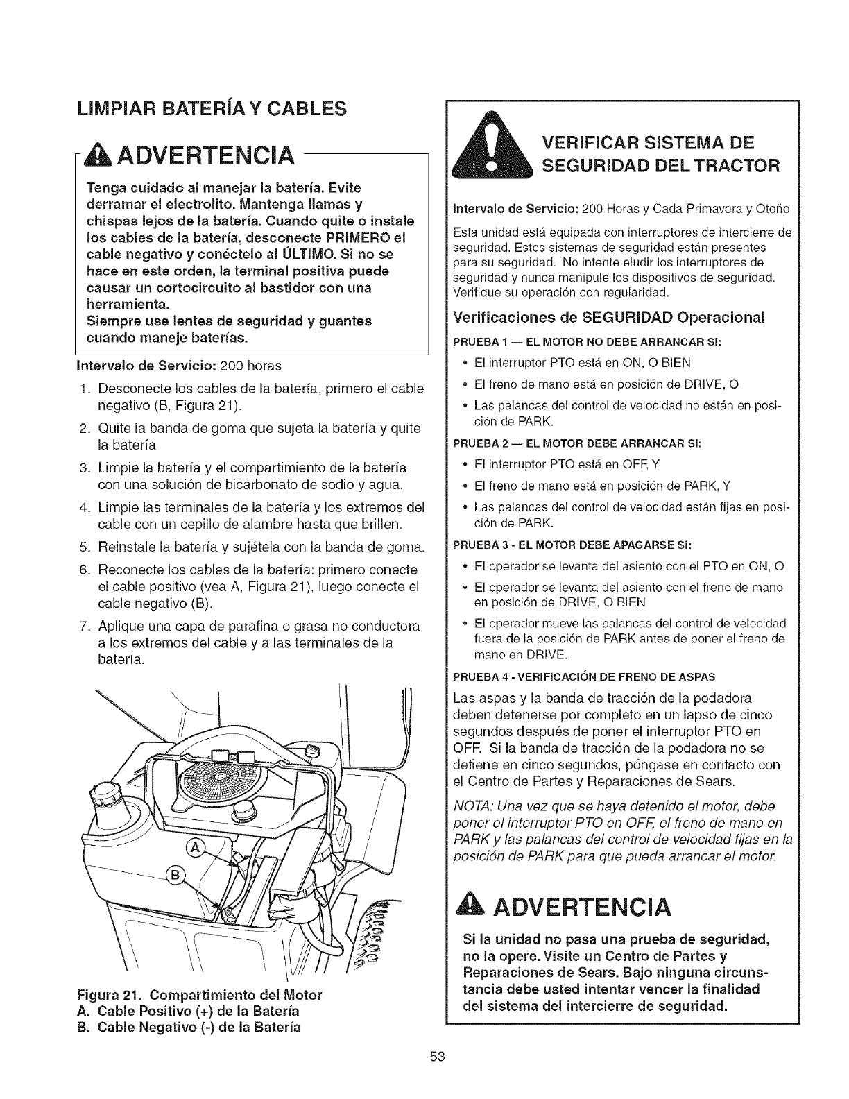
LIMPIAR BATERiAY CABLES
ADVERTENCIA
Tenga cuidado al manejar la bateda. Evite
derramar el electrolito. Mantenga llamas y
chispas lejos de la bateria. Cuando quite o instale
los cables de la bateria, desconecte PRIMERO el
cable negativo y con_ctelo al ULTIMO. Si no se
hace en este orden, la terminal positiva puede
causar un cortocircuito al bastidor con una
herramienta.
Siempre use lentes de seguridad y guantes
cuando maneje baterias.
Intervalo de Servicio: 200 horas
1. Desconecte los cables de la bateria, primero el cable
negativo (B, Figura 21).
2. Quite la banda de goma que sujeta la bateria y quite
la bateria
3. Limpie la bateria y el compartimiento de la bateria
con una soluci6n de bicarbonato de sodio y agua.
4. Limpie las terminales de la bateria y los extremos del
cable con un cepillo de alambre hasta que brillen.
5. Reinstaie ia bateria y suj_teia con ia banda de goma.
6. Reconecte los cables de la bateria: primero conecte
el cable positivo (vea A, Figura 21), luego conecte el
cable negativo (B).
7. Aplique una capa de parafina o grasa no conductora
a los extremos del cable y alas terminales de la
bateria.
Figura 21. Compartimiento del Motor
A. Cable Positivo (+) de la Bateria
El. Cable Negativo (=) de la Bateria
VERiFICAR SISTEMA DE
SEGURIDAD DEL TRACTOR
Intervalo de Servicio: 200 Horas y Cada Primavera y Otoho
Esta unidad esta equipada con interruptores de intercierre de
seguridad. Estos sistemas de seguridad estan presentes
para su seguridad. No intente eludir los interruptores de
seguridad y nunca manipule los dispositivos de seguridad.
Verifique su operaci6n con regularidad.
Verificaciones de SEGURIDAD Operacional
PRUEBA 1 -- EL MOTOR NO DEBE ARRANCAR Sl:
,, El interruptor PTO estb_en ON, O BIEN
,, El freno de mano est_ en posici6n de DRIVE, O
,, Las palancas del control de velocidad no est_n en posi-
cion de PARK.
PRUEBA 2 -- EL MOTOR DEBE ARRANCAR SI:
, El interruptor PTO estA en OFF, Y
, El freno de mano estA en posici6n de PARK, Y
, Las palancas del control de velocidad estan fijas en posi-
ciSn de PARK.
PRUEBA 3-EL MOTOR DEBE APAGARSE Sl:
,, El operador se levanta del asiento con el PTO en ON, O
,, El operador se levanta del asiento con el freno de mano
en posici6n de DRIVE, O BIEN
,, El operador mueve las palancas del control de velocidad
fuera de la posici6n de PARKantes de poner el freno de
mano en DRIVE.
PRUEBA4 -VERIFICACION DEFRENODEASPAS
Las aspas y ia banda de tracci6n de ia podadora
deben detenerse pot compieto en un lapso de cinco
segundos despu6s de poner el interruptor PTO en
OFR Si la banda de tracci6n de la podadora no se
detiene en cinco segundos, p6ngase en contacto con
el Centro de Partes y Reparaciones de Sears.
NOTA: Una vez que se haya detenido el motor, debe
poner el interrupter PTO en OFF, el freno de mane en
PARK y /as palancas del control de velocidad fijas en la
posicion de PARK para que pueda arrancar el motor.
ADVERTENCIA
Si la unidad no pasa una prueba de seguridad,
no la opere. Visite un Centro de Partes y
Reparaciones de Sears. Bajo ninguna circuns-
tancia debe usted intentar veneer la finalidad
del sistema del intercierre de seguridad.
53
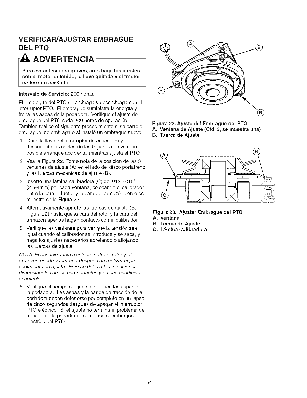
VERIFICAR/AJUSTAR EMBRAGUE
DEL PTO
ADVERTENCIA
Para evitar lesiones graves, s61o haga los ajustes
con el motor detenido, la Ilave quitada y el tractor
en terreno niveiado.
Intervalo de Servicio: 200 horas.
El embrague del PTO se embraga y desembraga con el
interruptor PTO. El embrague suministra la energia y
frena las aspas de la podadora. Verifique el ajuste del
embrague del PTO cada 200 horas de operaci6n.
Tambi_n realice el siguiente procedimiento si se barre el
embrague, no embraga o si instal6 un embrague nuevo.
1. Quite la Ilave del interruptor de encendJdo y
desconecte los cables de las bujias para evitar un
posible arranque accidental mientras ajusta el PTO.
2. Vea la Figura 22. Tome nota de la posici6n de las 3
ventanas de ajuste (A) en el lado del disco portafreno
y las tuercas mecanicas de ajuste (B).
3. Inserte una I_.mina calibradora (C) de .012"-.015"
(2.5-4mm) pot cada ventana, colocando el calibrador
entre la cara del rotor y la cara del armaz6n como se
muestra en la Figura 23.
4. AIternativamente apriete las tuercas de ajuste (B,
FJgura 22) hasta que la cara del rotor y la cara del
armaz6n apenas hagan contacto con el calibrador.
5. Verifique las ventanas para vet que la tensi6n sea
igual cuando el calJbrador se introduce y se saca, y
haga los ajustes necesarios apretando o afiojando
las tuercas de ajuste.
NOTA: El espacio vacfo existente entre el rotor y el
armazon puede variar adn despues de realizar el pro-
cedimiento de ajuste. Esto se debe a/as variaciones
dimensionales de los componentes yes una condicidn
aceptable.
6. Verifique el tiempo en que se detienen las aspas de
la podadora. Las aspas y la banda de tracci6n de la
podadora deben detenerse pot completo en un lapso
de cinco segundos despu_s de apagar el interruptor
PTO electrico. Si el ajuste no termina el problema de
frenado de la podadora, reemplace el embrague
electrico del PTO.
Figura 22. Ajuste del Embrague del PTO
A. Ventana de Ajuste (Ctd. 3, se muestra una)
B. Tuerca de Ajuste
Figura 23. Ajustar Embrague del PTO
A. Ventana
B. Tuerca de Ajuste
C. L&mina Calibradora
54
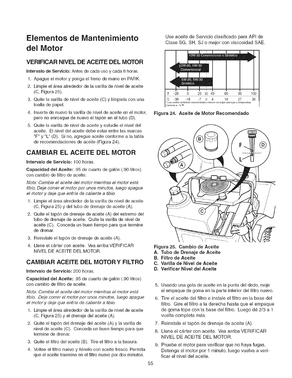
Elementos de Mantenirniento
del Motor
VERIFICAR NIVEL DE ACEITE DEL MOTOR
Intervalo de Servicio: Antes de cada uso y cada 8 horas.
1. Apague el motor y ponga el freno de mano en PARK.
2. Limpie el b.rea alrededor de la varilla de nivel de aceite
(C, Figura 25).
3. Quite la varilla de nivel de aceite (C) y I{mpiela con una
toalla de papel.
4. Inserte de nuevo la varilla de nivel de aceite en el motor,
pero no enrosque de nuevo el tap6n en el tubo (D).
5. Quite la varilla de nivel de aceite y estudie el nivel del
aceite. El nivel del aceite debe estar entre las marcas
"F" y "L" (D). Si no, agregue aceite conforme a la tabla
de recomendaciones de aceite (Figura 24).
CAMBIAR EL ACEITE DEL MOTOR
Intervalo de Servicio: 100 horas.
Capacidad del Aceite: .95 de cuarto de gal6n (.90 litros)
con cambio de filtro de aceite.
Nota: Cambie el aceite del motor mientras el motor esta
tibio, Deje correr el motor por unos minutos, luego apague
el motor y deje que enfrfe de caliente a tibio,
1. Limpie el b,rea aJrededor de la varilla de nivel de aceite
(C, Figura 25) y del tubo de drenaje de aceite (A).
2. Quite el tap6n de drenaje de aceite (A) del extremo del
tubo de drenaje de aceite. Quite la varilla de nivel de
aceite (C). Conceda un buen tiempo para que termine
de drenar.
3. Reinstale el tap6n de drenaje de aceite (A).
4. Llene el carter con aceite. Vea arribaVERIFICAR
NIVEL DE ACEITE DEL MOTOR.
CAMBIAR ACEITE DEL MOTOR Y FILTRO
Intervalo de Servicio: 200 horas.
Capacidad del Aceite: .95 de cuarto de gal6n (.90 litros)
con cambio de filtro de aceite.
Nota: Cambie el aceite del motor mientras el motor esta
tibio, Deje correr el motor por unos minutos, luego apague
el motor y deje que enfrfe de caliente a tibio,
1. Limpie el Area alrededor de la varilla de nivel de aceite
(C, Figura 25) y el drenaje del aceite (A).
2. Quite el tap6n del drenaje del aceite (A) y la varilla de
nivel de aceite (C). Conceda un buen tiempo para que
termine de drenar.
3. Quite el filtro del aceite (B). Tire el filtro a la basura.
4. Voltee el filtro nuevo y II_nelo con aceite fresco. Permita
que el aceite trasmine en el filtro nuevo pot dos minutos.
Use aceite de Servicio clasificado para API de
Clase SG, SH, SJ o mejor con viscosidad SAE.
m
,q m
°F -20 0 20 32 40 60 80 100
°C -30 -18 -7 0 4 16 27 38
Los aceites sinteticos recomendados ofrecen un mejor arranque a temperatura
rnenores a -IO'F
Figura 24. Aceite de Motor Recomendado
Figura 25. Cambio de Aceite
A. Tubo de Drenaje de Aceite
B. Filtro de Aceite
C. Varilla de NiveJ de Aceite
D. Verificar NiveJ deJ Aceite
55
5. Usando una gota de aceite en la punta del dedo, moje
el empaque de goma en la parte inferior del filtro nuevo.
6. Tire el aceite del filtro e instale el filtro en la base del
filtro. Gire el filtro a la derecha hasta que el empaque
de goma tope con la base del filtro. Luego d6 2/3 a 1
vuelta completa mas.
7. Reinstale el tap6n de drenaje de aceite (A).
8. Llene el carter con aceite. Vea arriba VERIFICAR
NIVEL DE ACEITE DEL MOTOR.
Pruebe el motor para verificar que no haya fugas.
Detenga el motor pot 1 minuto, luego vuelva a veri-
ficar el nivel del aceite.
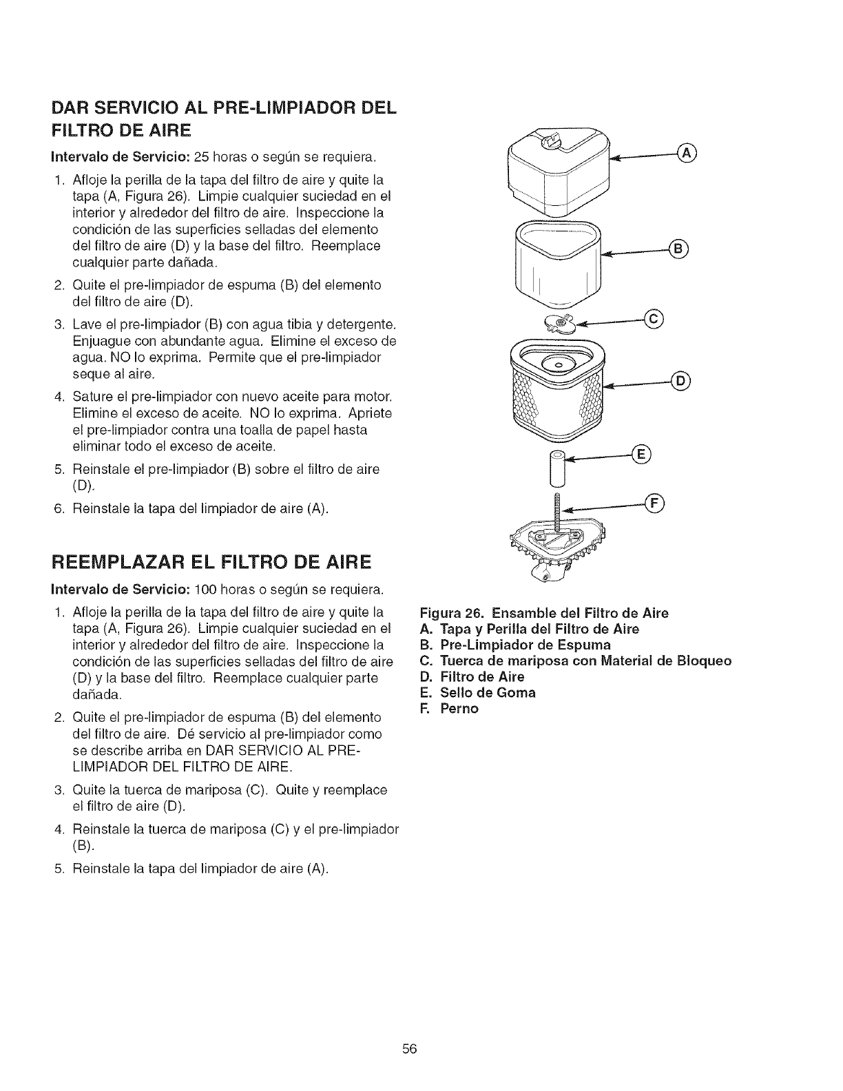
DAR SERVlCIO AL PRE-LIIVlPIADOR DEL
FILTRO DE AIRE
Intervalo de Servicio: 25 horas o segOn se requiera.
1. Afloje la perilla de la tapa del filtro de aire y quite la
tapa (A, Figura 26). Limpie cualquier suciedad en el
interior y alrededor del filtro de aire. Inspeccione la
condici6n de las superficies selladas del elemento
del filtro de aire (D) y la base del filtro. Reemplace
cualquier parte daSada.
2. Quite el pre-limpiador de espuma (B) del elemento
del filtro de aire (D).
3. Lave el pre-limpiador (B) con agua tibia y detergente.
Enjuague con abundante agua. Elimine el exceso de
agua. NO Io exprima. Permite que el pre-limpiador
seque al aire.
4. Sature el pre-limpiador con nuevo aceite para motor.
Elimine el exceso de aceite. NO Io exprima. Apriete
el pre-limpiador contra una toalla de papel hasta
eliminar todo el exceso de aceite.
5. Reinstale el pre-limpiador (B) sobre el filtro de aire
(U).
6. Reinstale la tapa del limpiador de aire (A).
REEIVIPLAZAR EL FILTRO DE AIRE
Intervalo de Servicio: 100 horas o segOn se requiera.
1. Afloje la perilla de la tapa del filtro de aire y quite la
tapa (A, Figura 26). Limpie cualquier suciedad en el
interior y alrededor del filtro de aire. Inspeccione la
condici6n de las superficies selladas del filtro de aire
(D) y la base del filtro. Reemplace cualquier parte
daSada.
2. Quite el pre-limpiador de espuma (B) del elemento
del filtro de aire. D6 servicio al pre-limpiador como
se describe arriba en DAR SERVICIO AL PRE-
LIMPIADOR DEL FILTRO DE AIRE.
3. Quite la tuerca de mariposa (C). Quite y reemplace
el filtro de aire (D).
4. Reinstale la tuerca de mariposa (C) y el pre-limpiador
(B).
5. Reinstale la tapa del limpiador de aire (A).
Figura 26. Ensamble del Filtro de Aire
A. Tapa yPerilla del Filtro de Aire
B. Pre-Limpiador de Espuma
C. Tuerca de mariposa con Material de Bloqueo
D. Filtro de Aire
E. Sello de Goma
F. Perno
56
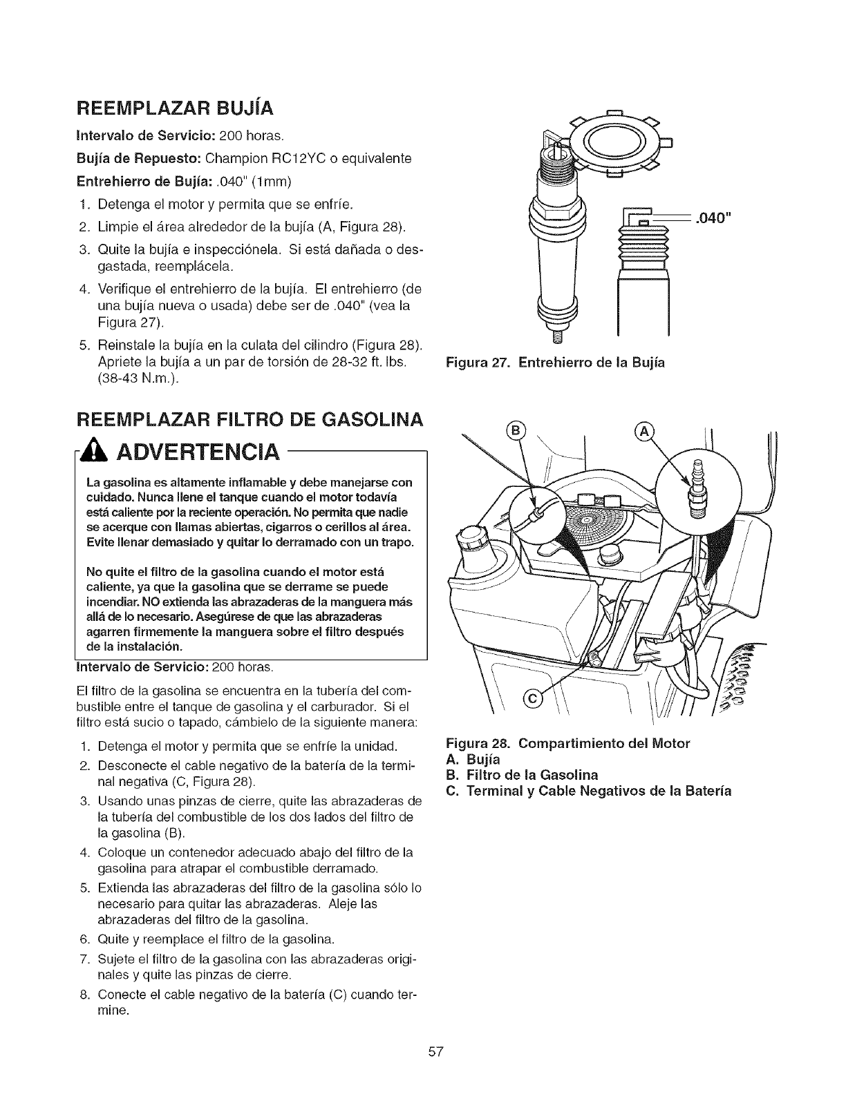
REEIVIPLAZAR BUJiA
IntervaJo de Servicio: 200 horas.
Bujia de Repuesto: Champion RC12YC o equivalente
Entrehierro de Bujia: .040" (1ram)
1. Detenga el motor y permita que se enfrfe.
2. Limpie el Area alrededor de la bujia (A, Figura 28).
3. Quite la bujia e inspecci6nela. Si est,. da_ada o des-
gastada, reempl_.cela.
4. Verifique el entrehierro de la bujia. El entrehierro (de
una bujia nueva o usada) debe set de .040" (vea la
Figura 27).
5. Reinstale la bujia en la culata del cilindro (Figura 28).
Apriete la bujia a un par de torsi6n de 28-32 ft. Ibs.
(38-43 N.m.).
REEIVIPLAZAR FILTRO DE GASOLINA
ADVERTENCIA
La gasolina es altamente inflamable y debe manejarse con
cuidado. Nunca llene emtanque cuando el motor todavia
esta caliente pot la reciente operaci6n. No permita que nadie
se acerque con llamas abiertas, cigarros o cerillos al &tea.
Evite llenar demasiado y quitar Io derramado con un trapo.
No quite el filtro de la gasolina cuando el motor esta
caliente, ya que la gasolina que se derrame se puede
incendiar. NO extienda las abrazaderas de la manguera mas
alia de Io necesario. Aseg_rese de que las abrazaderas
agarren firmemente la manguera sobre el filtro despu_s
de la instalacion.
Intervalo de Servicio: 200 horas.
El filtro de la gasolina se encuentra en la tuberfa del com-
bustible entre el tanque de gasolina y el carburador. Si el
filtro estb, sucio o tapado, cb,mbielo de la siguiente manera:
1. Detenga el motor y permita que se enfrfe la unidad.
2. Desconecte el cable negativo de la baterfa de la termi-
nal negativa (C, Figura 28).
3. Usando unas pinzas de cierre, quite las abrazaderas de
la tuberfa del combustible de los dos lados del filtro de
la gasolina (B).
4. Coloque un contenedor adecuado abajo del filtro de la
gasolina para atrapar el combustible derramado.
5. Extienda las abrazaderas del filtro de la gasolina s61o Io
necesario para quitar las abrazaderas. Aleje las
abrazaderas del filtro de la gasolina.
6. Quite y reemplace el filtro de la gasolina.
7. Sujete el filtro de la gasolina con las abrazaderas origi-
nales y quite las pinzas de cierre.
8. Conecte el cable negativo de la baterfa (C) cuando ter-
mine.
Figura 27. Entrehierro de Ja Bujia
Figura 28. Compartimiento deJ Motor
A. Bujia
B. Filtro de la Gasolina
C. Terminal y Cable Negativos de la Bateria
57
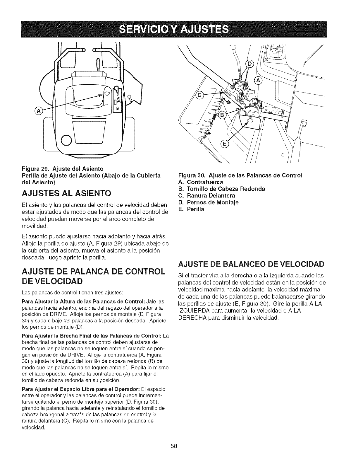
\/
\
Figura 29. Ajuste del Asiento
Perilla de Ajuste del Asiento (Abajo de la Cubierta
del Asiento)
AJUSTES AL ASIENTO
El asiento y las palancas del control de velocidad deben
estar ajustados de modo que las palancas del control de
velocidad puedan moverse pot el arco completo de
movilidad.
El asiento puede ajustarse hacia adelante y hacia atrb,s.
Afloje la perilla de ajuste (A, Figura 29) ubicada abajo de
la cubierta del asiento, mueva el asiento a la posici6n
deseada, luego apriete la perilla.
AJUSTE DE PALANCA DE CONTROL
DE VELOCIDAD
Las palancas de control tienen tres ajustes:
Para Ajustar la Altura de las Palancas de Control: Jale las
palancas hacia adentro, encima del regazo del operador a la
posici6n de DRIVE. Afloje los pernos de montaje (D, Figura
30) y suba o baje las palancas a la posici6n deseada. Apriete
los pernos de montaje (D).
Para Ajustar la Brecha Final de las Palancas de Control: La
brecha final de las palancas de control deben ajustarse de
modo que las palancas no se toquen entre si cuando se pon-
gan en posici6n de DRIVE. Afloje la contratuerca (A, Figura
30) y ajuste la Iongitud del tornillo de cabeza redonda (B) de
modo que las palancas no se toquen entre si. Repita Io mismo
en el lado opuesto. Apriete la contratuerca (A) para fijar el
tornillo de cabeza redonda en su posici6n.
Para Ajustar el Espacio Libre para el Operador: El espacio
entre el operador y las palancas de control puede incremen-
tarse quitando el perno de montaje superior (D, Figura 30),
girando la palanca hacia adelante y reinstalando el tornillo de
cabeza hexagonal a traves de las palancas de control y la
ranura delantera (C). Repita Io mismo con la palanca de
velocidad.
Figura 30. Ajuste de las Palancas de Control
A. Contratuerca
B. Tornillo de Cabeza Redonda
C. Ranura Delantera
D. Pernos de Montaje
E. Perilla
AJUSTE DE BALANCEO DE VELOCIDAD
Si el tractor vira a la derecha o a la izquierda cuando las
palancas del control de velocidad est_.n en la posici6n de
velocidad maxima hacia adelante, la velocidad maxima
de cada una de las palancas puede balancearse girando
las perillas de ajuste (E, Figura 30). Gire la perilla A LA
IZQUIERDA para aumentar la velocidad o A LA
DERECHA para disminuir la velocidad.
58
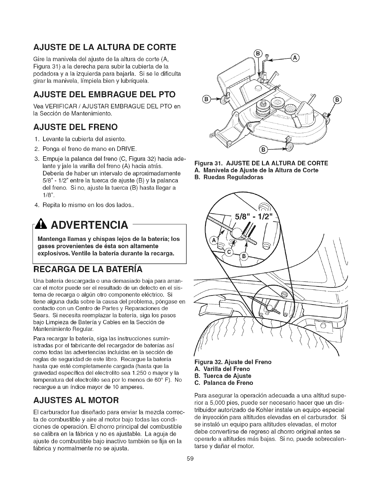
AJUSTE DE LA ALTURA DE CORTE
Gire la manivela del ajuste de la altura de corte (A,
Figura 31) a la derecha para subir la cubierta de la
podadora y a la izquierda para bajarla. Si se le dificulta
girar la manivela, limpiela bien y lubriquela.
AJUSTE DEL EMBRAGUE DEL PTO
Vea VERIFICAR/AJUSTAR EMBRAGUE DEL PTO en
la Secci6n de Mantenimiento.
AJUSTE DEL FRENO
1. Levante la cubierta del asiento.
2,
3.
Ponga el freno de mano en DRIVE.
Empuje la palanca del freno (C, Figura 32) hacia ade-
lante y jale la varilla del freno (A) hacia atrb,s.
Deberia de haber un intervalo de aproximadamente
5/8" - 1/2" entre la tuerca de ajuste (B) y la palanca
del freno. Si no, ajuste la tuerca (B) hasta Ilegar a
1/8".
4. Repita Io mismo en los dos lados..
A ADVERTENCIA
Mantenga llamas y chispas lejos de la bateria; los
gases provenientes de _sta son altamente
explosivos. Ventile la bateria durante la recarga.
RECARGA DE LA BATERIA
Una baterfa descargada o una demasiado baja para arran-
car el motor puede set el resultado de un defecto en el sis-
tema de recarga o algun otto componente el6ctrico. Si
tiene alguna duda sobre la causa del problema, p6ngase en
contacto con un Centro de Partes y Reparaciones de
Sears. Si necesita reemplazar la baterfa, siga los pasos
bajo Limpieza de Baterfa y Cables en la Secci6n de
Mantenimiento Regular.
Para recargar la baterfa, siga las instrucciones sumin-
istradas per el fabricante del recargador de baterfas asf
como todas las advertencias incluidas en la secci6n de
reglas de seguridad de este libro. Recargue la baterfa
hasta que est_ completamente cargada (hasta que la
gravedad especffica del electrolito sea 1.250 o mayor y la
temperatura del electrolito sea pot Io menos de 60 ° F). No
recargue a un fndice mayor de 10 amperes.
AJUSTES AL MOTOR
El carburador rue diseSado para enviar la mezcla correc-
ta de combustible y aire al motor bajo todas las condi-
ciones de operaci6n. El chorro principal del combustible
se calibra en la f_.brica y no es ajustable. La aguja de
ajuste de combustible bajo inactivo tambien se fija en la
f_.brica y normalmente no se ajusta.
Figura 31. AJUSTE DE LA ALTURA DE CORTE
A. Manivela de Ajuste de la AItura de Corte
B. Ruedas Reguladoras
Figura 32. Ajuste del Freno
A. Varilla del Freno
B. Tuerca de Ajuste
C. Palanca de Freno
Para asegurar la operaci6n adecuada a una altitud supe-
rior a 5,000 pies, puede set necesario hacer que un dis-
tribuidor autorizado de Kohler instale un equipo especial
de inyecci6n para altitudes elevadas en el carburador. Si
se instal6 un equipo para altitudes elevadas, el motor
debe convertirse de regreso al chorro original antes se
operarlo a altitudes mas bajas. Si no, puede sobrecalen-
tarse y daSar el motor.
59
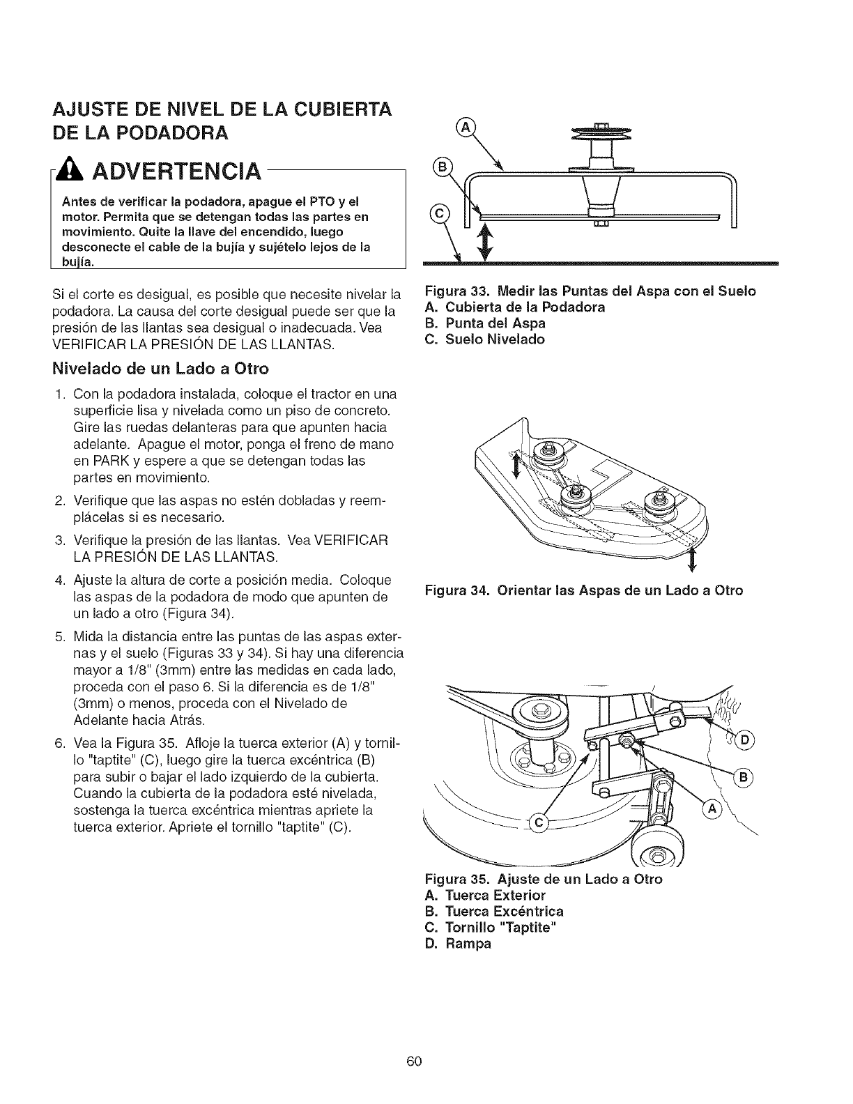
AJUSTE DE NIVEL DE LA CUBIERTA
DE LA PODADORA
ADVERTENCIA
Antes de verificar la podadora, apague el PTO yel
motor. Permita que se detengan todas las partes en
movimiento. Quite la llave del encendido, luego
desconecte el cable de la bujia ysuj_telo lejos de la
bujia.
Si el corte es desigual, es posible que necesite nivelar la
podadora. La causa del corte desigual puede set que la
presi6n de las Ilantas sea desigual o inadecuada. Vea
VERIFICAR LA PRESlON DE LAS LLANTAS.
Nivelado de un Lado a Otto
1. Con la podadora instalada, coloque el tractor en una
superficie lisa y nivelada como un piso de concreto.
Gire las ruedas delanteras para que apunten hacia
adelante. Apague el motor, ponga el freno de mano
en PARK y espere a que se detengan todas las
partes en movimiento.
2. Verifique que las aspas no est6n dobladas y reem-
pl_.celas si es necesario.
3. Verifique la presi6n de las Ilantas. Vea VERIFICAR
LA PRESlON DE LAS LLANTAS.
4. Ajuste la altura de corte a posici6n media. Coloque
las aspas de la podadora de modo que apunten de
un lado a otto (Figura 34).
5. Mida la distancia entre las puntas de las aspas exter-
nas y el suelo (Figuras 33 y 34). Si hay una diferencia
mayor a 1/8" (3mm) entre las medidas en cada lado,
proceda con el paso 6. Si la diferencia es de 1/8"
(3ram) o menos, proceda con el Nivelado de
Adelante hacia Atras.
6. Vea la Figura 35. Afloje la tuerca exterior (A) y tornil-
Io "taptite" (C), luego gire la tuerca exc6ntrica (B)
para subir o bajar el lado izquierdo de la cubierta.
Cuando la cubierta de la podadora este nivelada,
sostenga la tuerca exc6ntrica mientras apriete la
tuerca exterior. Apriete el tornillo "taptite" (C).
\
u,.3u
Figuta 33. Medit lae Puntas del Aspa con el Suelo
A. Cubietta de la Podadora
B. Punta del Aspa
C. Suelo Nivelado
Figuta 34. Orientar las Aspas de un Lado aOtto
Figuta 35. Ajuste de un Lado a Otto
A. Tuetca Exterior
B. Tuerca Exc_nttica
C. Tomillo "Taptite"
D. Rampa
6O
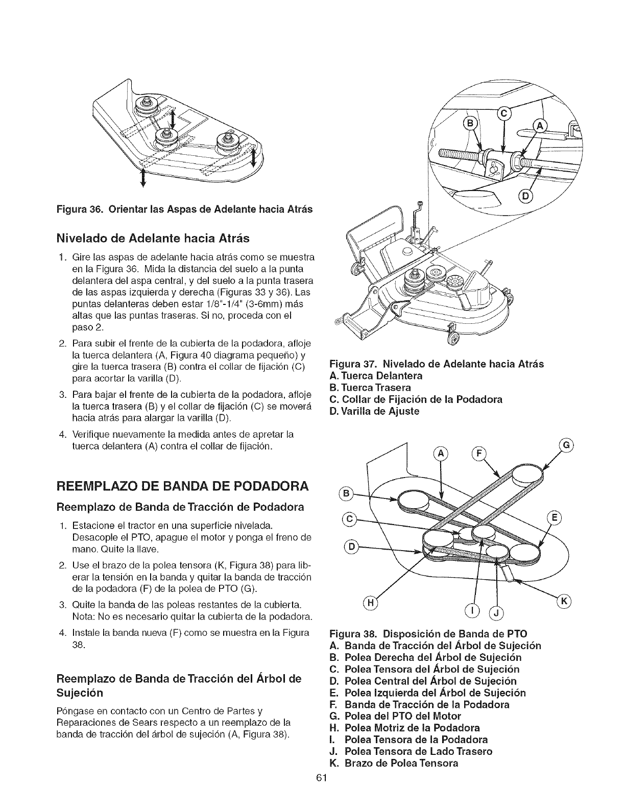
Figura 36. Orientar las Aspas de Adelante hacia Atrbs
Nivelado de Adelante hacia Atr_s
1. Gire las aspas de adelante hacia atrb,s como se muestra
en la Figura 38. Mida la distancia del suelo a la punta
delantera del aspa central, y del suelo a la punta trasera
de las aspas izquierda y derecha (Figuras 33 y 38). Las
puntas delanteras deben estar 1/8"-1/4" (3-Smm) mb,s
altas que las puntas traseras. Si no, proceda con el
paso 2.
2. Para subir el frente de la cubierta de la podadora, afloje
la tuerca delantera (A, Figura 40 diagrama pequeSo) y
gire la tuerca trasera (B) contra el collar de fijaciTn (C)
para acortar la varilla (D).
3. Para bajar el frente de la cubierta de la podadora, afloje
la tuerca trasera (B) y el collar de fijaciTn (C) se moverb,
hacia atrb,s para alargar la varilla (D).
4. Verifique nuevamente la medida antes de apretar la
tuerca delantera (A) contra el collar de fijaciTn.
Figura 37. Nivelado de Adelante hacia Atr_s
A. Tuerca Delantera
B. Tuerca Trasera
C. Collar de Fijaci6n de la Podadora
D. Varilla de Ajuste
REEMPLAZO DE BANDA DE PODADORA
Reemplazo de Banda de Traccion de Podadora
1. Estacione el tractor en una superficie nivelada.
Desacople el PTO, apague el motor y ponga el freno de
mano. Quite la Ilave.
2. Use el brazo de la polea tensora (K, Figura 38) para lib-
erar la tensiTn en la banda y quitar la banda de tracciTn
de la podadora (F) de la polea de PTO (G).
3. Quite la banda de las poleas restantes de la cubierta.
Nota: No es necesario quitar la cubierta de la podadora.
4. Instale la banda nueva (F) como se muestra en la Figura
38.
Reemplazo de Banda de Traccion del Arbol de
Sujecion
P6ngase en contacto con un Centre de Partes y
Reparaciones de Sears respecto a un reemplazo de la
banda de tracciTn del b,rbol de sujeciTn (A, Figura 38).
Figura 38. Disposici6n de Banda de PTO
A. Banda de TracciTn del Arbol de Sujeci6n
B. Polea Derecha del Arbol de SujeciTn
C. Polea Tensora del Arbol de Sujeci6n
D. Polea Central del Arbol de SujeciTn
E. Polea Izquierda del Arbol de SujeciTn
F. Banda deTracciTn de la Podadora
G. Polea del PTO del Motor
H. Polea Motriz de la Podadora
I. PoleaTensora de la Podadora
J. Polea Tensora de Lado Trasero
K. Brazo de Polea Tensora
61
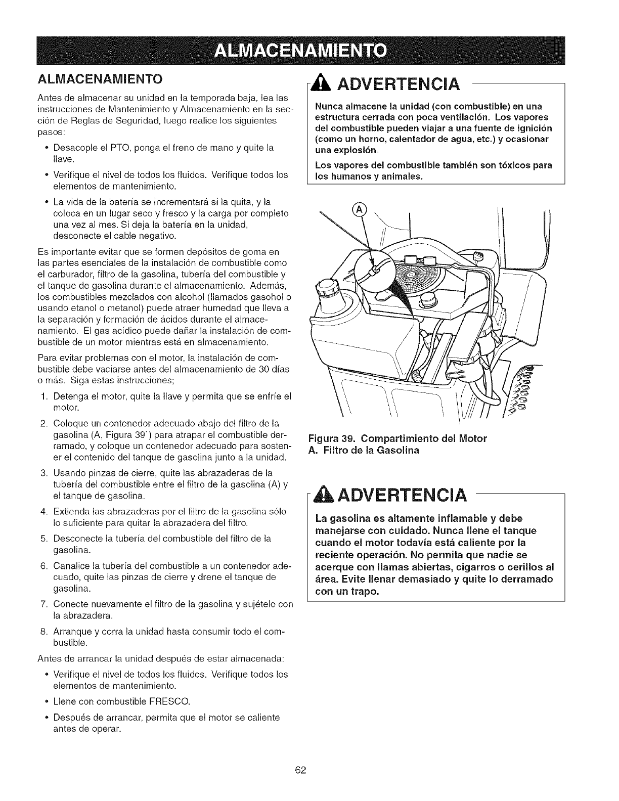
ALMACENAMIENTO
Antes de almacenar su unidad en la temporada baja, lea las
instrucciones de Mantenimiento y Almacenamiento en la sec-
ci6n de Reglas de Seguridad, luego realice los siguientes
pasos:
,, Desacople el PTO, ponga el freno de mano y quite la
Ilave.
Verifique el nivel de todos los fiuidos. Verifique todos los
elementos de mantenimiento.
,, La vida de la bater[a se incrementar_, si la quita, y la
coloca en un lugar seco y fresco y la carga por complete
una vez al rues. Si deja la bater[a en la unidad,
desconecte el cable negative.
Es importante evitar que se formen dep6sitos de goma en
las partes esenciales de la instalaci6n de combustible como
el carburador, filtro de la gasolina, tuber[a del combustible y
el tanque de gasolina durante el almacenamiento. Adema.s,
los combustibles mezclados con alcohol (llamados gasohol o
usando etanol o metanol) puede atraer humedad que Ileva a
la separaci6n y formaci6n de a.cidos durante el almace-
namiento. El gas ac[dico puede da_ar la instalaci6n de com-
bustible de un motor mientras est&. en almacenamiento.
Para evitar problemas con el motor, la instalaci6n de com-
bustible debe vaciarse antes del almacenamiento de 30 d[as
o m_.s. Siga estas instrucciones;
1. Detenga el motor, quite la Ilave y permita que se enfr[e el
motor.
2. Coloque un contenedor adecuado abajo del filtro de la
gasolina (A, Figura 39") para atrapar el combustible der-
ramado, y coloque un contenedor adecuado para sosten-
er el contenido del tanque de gasolina junto a la unidad.
3. Usando pinzas de cierre, quite las abrazaderas de la
tuber[a del combustible entre el filtro de la gasolina (A) y
el tanque de gasolina.
4. Extienda las abrazaderas pot el filtro de la gasolina s61o
Io suficiente para quitar la abrazadera del filtro.
5. Desconecte la tuber[a del combustible del filtro de la
gasolina.
6. Canalice la tuber[a del combustible a un contenedor ade-
cuado, quite las pinzas de cierre y drene el tanque de
gasolina.
7. Conecte nuevamente el filtro de la gasolina y sujetelo con
la abrazadera.
ADVERTENCIA
Nunca almacene la unidad (con combustible) en una
estructura cerrada con poca ventilaci6n. Los vapores
del combustible pueden viajar auna fuente de ignicibn
(como un homo, calentador de agua, etc,) y ocasionar
una explosi6n.
Los vapores del combustible tambien son t6×icos para
los humanos y animales.
Figura 39. Compartimiento del Motor
A. Filtro de la Gasolina
- ADVERTENCIA
La gasolina es altamente inflamable y debe
manejarse con cuidado. Nunca llene el tanque
cuando el motor todavia est_ caliente pot la
reciente operaci6n. No permita que nadie se
acerque con llamas abiertas, cigarros o cerillos al
&tea. Evite llenar demasiado y quite Io derramado
con un trapo.
8. Arranque y corra la unidad hasta consumir todo el com-
bustible.
Antes de arrancar la unidad despues de estar almacenada:
oVerifique el nivel de todos los fiuidos. Verifique todos los
elementos de mantenimiento.
Llene con combustible FRESCO.
oDespues de arrancar, permita que el motor se caliente
antes de operar.
62
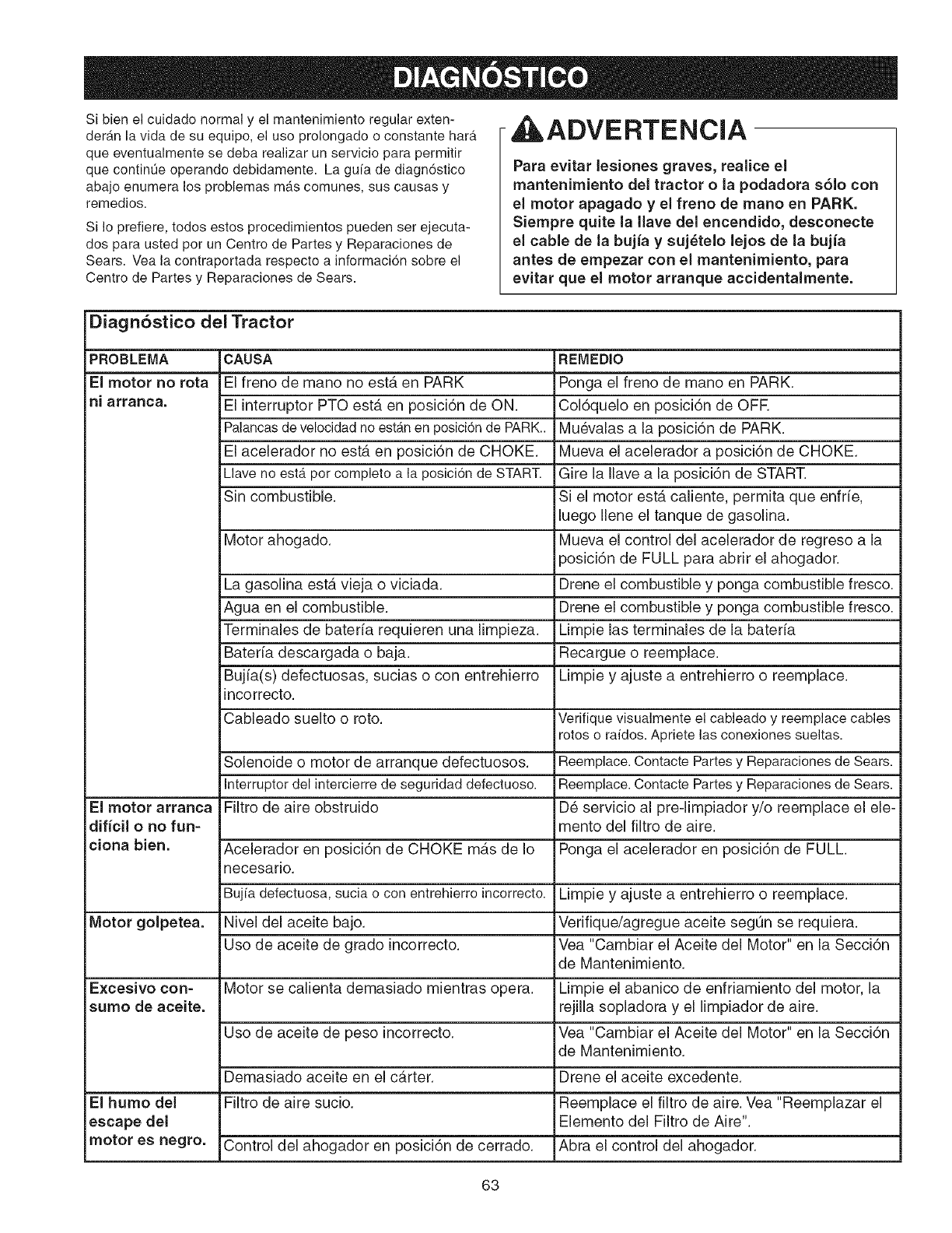
Si bien el cuidado normal y el mantenimiento regular exten-
derAn la vida de su equipo, el uso prolongado o constante hath,
que eventualmente se deba realizar un servicio para permitir
que contint]e operando debidamente. La gufa de diagn6stico
abajo enumera los problemas mAs comunes, sus causas y
remedios.
Si Io prefiere, todos estos procedimientos pueden ser ejecuta-
dos para usted pot un Centro de Partes y Reparaciones de
Sears. Vea la contraportada respecto a informaci6n sobre el
Centro de Partes y Reparaciones de Sears.
,ADVERTENCIA
Para evitar lesiones graves, reaiice el
mantenimiento del tractor o la podadora s61o con
el motor apagado y el freno de mano en PARK.
Siempre quite la llave del encendido, desconecte
el cable de la bujJa y suj_telo lejos de la bujJa
antes de empezar con el mantenimiento, para
evitar que el motor arranque accidentalmente.
Diagn6stico del Tractor
PROBLEMA CAUSA REMEDIO
El motor no rota El freno de mano no est,. en PARK Ponga el freno de mano en PARK.
ni arranca. El interruptor PTO esta en posici6n de ON. Col6quelo en posici6n de OFR
Palancasdevelocidadno est_nen posicionde PARK.. Mu6valas a la posici6n de PARK.
El acelerador no est,. en posici6n de CHOKE. Mueva el acelerador a posici6n de CHOKE.
Llave no est;Jpor completo a la posici6n de START. Gire la Ilave a la posici6n de START.
Sin combustible. Si el motor esta caliente, permita que enfrie,
luego Ilene el tanque de gasolina.
Motor ahogado. Mueva el control del acelerador de regreso a la
posici6n de FULL para abrir el ahogador.
La gasolina esta vieja o viciada. Drene el combustible y ponga combustible fresco.
Agua en el combustible. Drene el combustibJe y ponga combustibJe fresco.
Terminales de bateria requieren una limpieza. Limpie las terminales de la bateria
Bateria descargada o baja. Recargue o reemplace.
Bujia(s) defectuosas, sucias o con entrehierro Limpie y ajuste a entrehierro o reemplace.
incorrecto.
Cableado suelto o roto. Verifique visualmente el cableado y reemplace cables
rotos o raidos.Apriete las conexiones sueltas.
Solenoide o motor de arranque defectuosos. Reemplace.Contacte Partesy Reparacionesde Sears.
Interruptor del intercierre de seguridad defectuoso. Reemplace.Contacte Partesy Reparacionesde Sears.
El motor arranca Filtro de aire obstruido D6 servicio al pre-limpiador y/o reemplace el ele-
dJfJcil ono fun- mento del filtro de aire.
ciona bien. Acelerador en posici6n de CHOKE m_.s de Io Ponga el acelerador en posici6n de FULL.
necesafio.
Buj[a defectuosa, sucia o con entrehierro incorrecto. Limpie y ajuste a entrehierro o reemplace.
Motor golpetea. Nivel del aceite bajo. Verifique/agregue aceite segQn se requiera.
Uso de aceite de grado incorrecto. Vea "Cambiar el Aceite del Motor" en la Secci6n
de Mantenimiento.
Excesivo con- Motor se calienta demasiado mientras opera. Limpie el abanico de enfdamiento del motor, la
sumo de aceite, rejilla sopladora y el limpiador de aire.
Uso de aceite de peso incorrecto. Vea "Cambiar el Aceite del Motor" en la Secci6n
de Mantenimiento.
Demasiado aceite en el carter. Drene el aceite excedente.
El humo del Filtro de aire sucio. Reemplace el filtro de aire. Vea "Reemplazar el
escape del Elemento del Filtro de Aire".
motor es negro. Control del ahogador en posici6n de cerrado. Abra el control del ahogador.
63
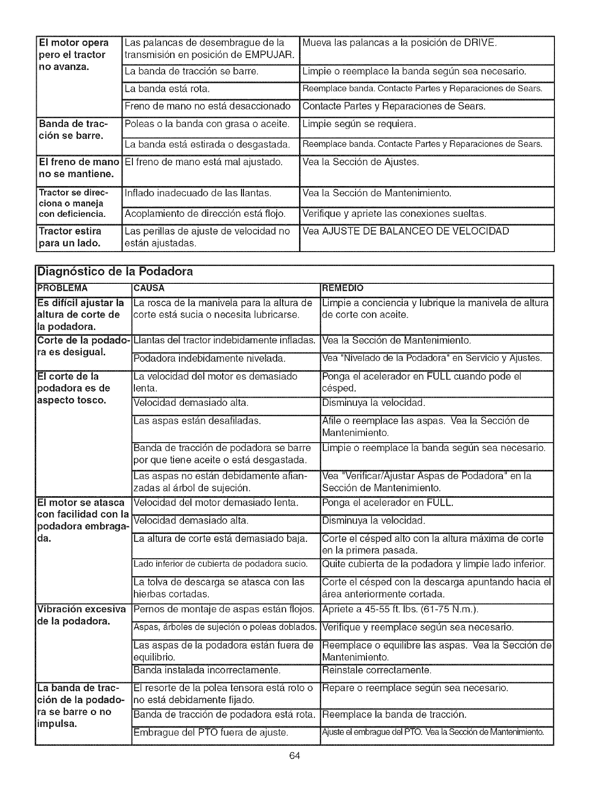
Elmotoropera Laspalancasdedesembraguedela Muevalaspalancasa laposici6nde DRIVE.
_eroeltractor transmisi6nenposici6ndeEMPUJAR.
noavanza. Labandadetracci6nsebarre. Limpieo reemplacelabandasegQnseanecesario.
LabandaestArota. Reemplacebanda.ContactePartesy ReparacionesdeSears.
FrenodemanonoestAdesaccionadoContactePartesy ReparacionesdeSears.
Bandadetrac- Poleaso labandacongrasaoaceite. LimpiesegQnserequiera.
ci6n se barre. La banda esta estirada o desgastada. Reemplace banda. Contacte Partes y Reparaciones de Sears.
El freno de mano El freno de mano esta mal ajustado. Vea la Secci6n de Ajustes.
no se mantiene.
Tractor se direc- Inflado inadecuado de las Ilantas. Vea la Secci6n de Mantenimiento.
ciona o maneja
con deficiencia. Acoplamiento de direcci6n estA fiojo. Vedfique y apriete las conexiones sueltas.
Tractor estira Las perillas de ajuste de velocidad no Vea AJUSTE DE BALANCEO DE VELOCIDAD
_ara un lado. estan ajustadas.
Diagn6stico de la Podadora
PROBLEMA CAUSA REMEDIO
Es dificil ajustar la La rosca de la manivela para la altura de Limpie a conciencia y lubrique la manivela de altura
altura de corte de corte esta sucia o necesita lubricarse, de corte con aceite.
la podadora.
Corte de la podado- Mantas del tractor indebidamente infladas. Vea la Secci6n de Mantenimiento.
ra es desigual. Podadora indebidamente nivelada. Yea "Nivelado de la Podadora" en Servicio y Ajustes.
El corte de la La velocidad del motor es demasiado Ponga el acelerador en FULL cuando pode el
_odadora es de lenta, cesped.
aspecto tosco. Velocidad demasiado alta. Disminuya la velocidad.
Las aspas estAn desafiladas. Afile o reemplace las aspas. Vea la Secci6n de
Mantenimiento.
Banda de tracci6n de podadora se barre Limpie o reemplace la banda segOn sea necesario.
pot que tiene aceite o estA desgastada.
Las aspas no estAn debidamente arian- Vea "Verificar/Ajustar Aspas de Podadora" en la
zadas al Arbol de sujeci6n. Secci6n de Mantenimiento.
El motor se atasca Velocidad del motor demasiado lenta. Ponga el acelerador en FULL.
con facilidad con la Velocidad demasiado alta. Disminuya la velocidad.
3odadora embraga-
da. La altura de corte estA demasiado baja. Corte el c6sped alto con la altura maxima de corte
en la primera pasada.
Lado inferior de cubierta de podadora sucio. Quite cubierta de la podadora y limpie lado inferior.
La tolva de descarga se atasca con las Corte el c6sped con la descarga apuntando hacia el
hierbas cortadas. Area anteriormente cortada.
Vibraci6n excesiva Pernos de montaje de aspas estan flojos. Apriete a 45-55 ft. Ibs. (61-75 N.m.).
de la podadora. Aspas, _rboles de sujeci6n o poleas doblados. Verifique y reemplace seg_n sea necesado.
Las aspas de la podadora estan fuera de Reemplace o equilibre las aspas. Vea la Secci6n de
equilibrio. Mantenimiento.
Banda instalada incorrectamente. Reinstale correctamente.
La banda de trac- El resorte de la polea tensora esta roto o Repare o reemplace segOn sea necesario.
ci6n de la podado- no estA debidamente fijado.
ra se barre ono Banda de tracci6n de podadora esta rota. Reemplace la banda de tracci6n.
impulsa. Embrague del PTO fuera de ajuste. AjusteelembraguedelPTO.YealaSecci6nde Mantenimiento.
64

RepairParts
PTS - 1
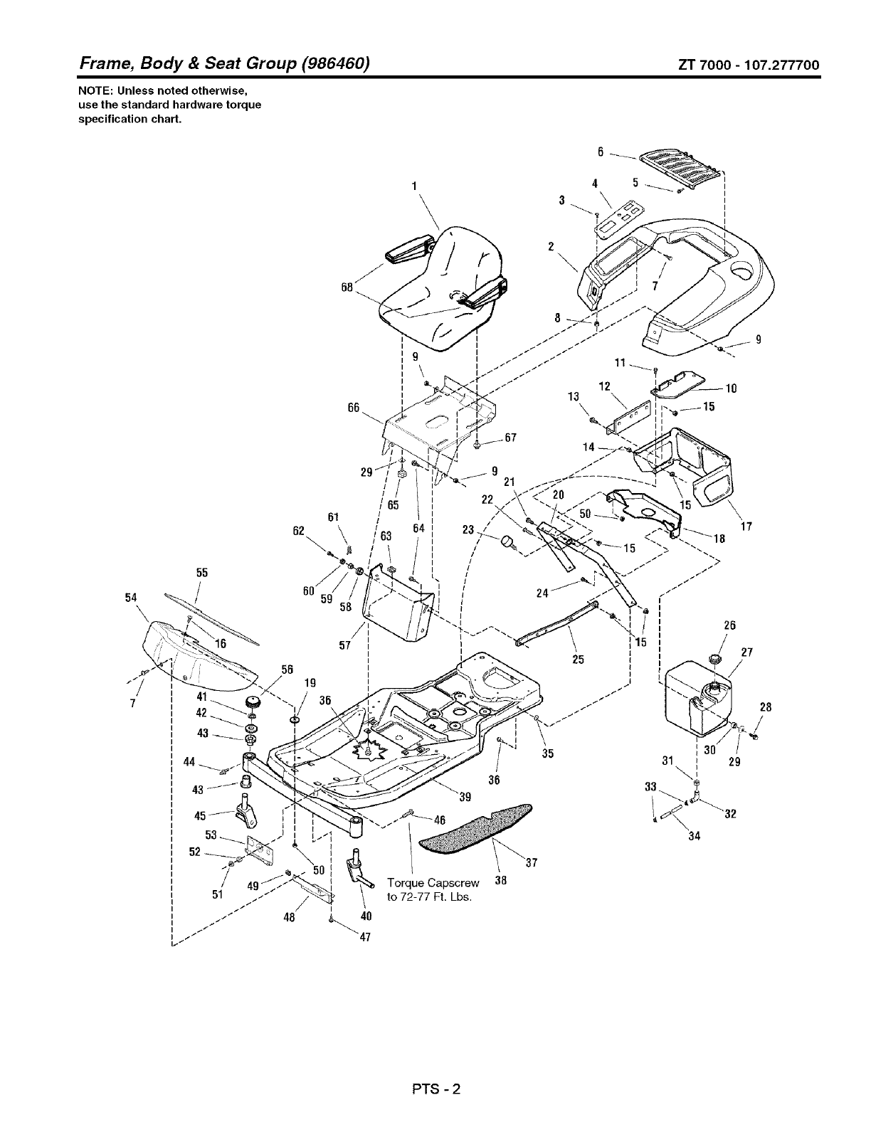
Frame, Body & Seat Group (986460) ZT 7000 -107.277700
NOTE: Unless noted otherwise,
use the standard hardware torque
specification chart,
66
1\
9\
54
55
/
41
42
61
62\ \
58 19
//
/85
/
i
/
/63
39
Torque Capscrew
to 72-77 Ft. Lbs.
48 _ 40
47
36
38
25
35
28
/27
28
,,J
31 29
\'
34
PTS - 2

Frame,
REF NO
1 1726018SM
2 1726305SM
3 1722293SM
4 1726369SM
5 1673320SM
6 1708504SM
7 1960715SM
8 1920397SM
9 1960694SM
10 1716027SM
11 1925003SM
12 1715961SM
13 1925205SM
14 1673796SM
15 1931277SM
16 1931317SM
17 1715962ASM
18 1726417SM
19 1960518SM
20 1725982SM
21 1923341SM
22 1922127SM
23 1726390SM
24 1921333SM
25 1708362ASM
26 1714020SM
27 1726397SM
28 1930600SM
29 1960606SM
30 1710437SM
31 1726400SM
32 1674792SM
33 2860112SM
34 1718678SM
35 1933988SM
36 1930591SM
37 1728986SM
38 1728987SM
39 1729629SM
40 1716065SM
41 2834712SM
42 1919394SM
43 1721682SM
44 2821133SM
45 1716066SM
46 1920328SM
47 1664847SM
48 1726024ASM
Footnotes
Body & Seat Group (986460)
PART NO. QTY. DESCRIPTION
ZT 7000-107.277700
1 SEAT ASSEMBLY, wth Arm Rests (Includes Ref. No. 68)
1 DECK, Seat
4 CAPSCREW, Hex, Socket Head, 1/4-20 x 7/8, G5
1 PLATE, Pod Control
3 RIVET, Pop
1 SCREEN, Seat Deck
4 SCREW, Truss Head Torx Drive, 1/4-20 x 3/4
4 NUT, Hex Lock ESNA Light, 1/4-20
6 NUT, Hex Flange ESNA, 1/4-20
1 PLATE, Battery
6 CAPSCREW, Hex Washer Head Taptite, 1/4-20 x 1/2, G5
1 SUPPORT, Reservoir
2 CAPSCREW, Hex Head, 5/16-18 x 5/8, G5
1 SPACER, Powdered Metal
8 NUT, Hex Flange Whiz Lock, 5/16-18
2 CARRIAGE BOLT, 1/4-20 x 3/4
1 SHROUD, Rear
1 DUCT, Air Inlet
2 NUT, Push, 1/4
1 SUPPORT, Seat Deck
1 CAPSCREW, Hex Head, 1/4-20 x 3/4, G5
1 CAPSCREW, Hex Head, 5/16-18 x 1-3/4, G5
2 BUMPER, Rubber
1 CAPSCREW, Hex Head, 5/16-18 x 1, G5
1 BRACE, Tank
1 CAP, Fuel Tank
1 TANK, Fuel
1 CAPSCREW, Hex Washer Head Taptite, 5/16-18 x 1-1/2
2 LOCKWASHER, Pyramidal, Hex, 3/4
1 SPACER
1 BUSHING, Fuel Tank
1 ELBOW, with Screen, Gas Tank To Fuel Line
2 CLAMP, Hose, Wire Type E
1 HOSE, Fuel
2 NUT, Push
6 CAPSCREW, Hex Flange Whiz Lock, 5/16-18 x 3/4
1 PAD, Footrest, R.H.
1 PAD, Footrest, L.H.
1 FRAME & SPINDLES ASSEMBLY (Includes Ref. Nos. 40, 41,42, 43, 44 & 45)
1 ARM, Caster, L.H.
2 RING, E-Retaining
4 WASHER
4 BUSHING
2 FITTING, Lube
1 ARM, Caster, R.H.
1 CAPSCREW, Hex Head, 1/2-13 x 1-1/2, G5
2 SCREW, Hex Washer Head Taptite, 5/16-18 x 3/4
1 BRACKET, Footrest Support
PTS - 3

Frame, Body & Seat Group (986460) ZT 7000 -107.277700
NOTE: Unless noted otherwise,
use the standard hardware torque
specification chart,
66
1\
9\
54
55
/
41
42
61
62\ \
58 19
//
/85
/
i
/
/63
39
Torque Capscrew
to 72-77 Ft. Lbs.
48 _ 40
47
36
38
25
35
28
/27
28
,,J
31 29
\'
34
PTS - 4

Frame, Body & Seat Group (986460)
REF NO PART NO, QTY, DESCRIPTION
49 1960368SM 2
50 1930641SM 3
51 1930644SM 1
52 1709235SM 1
53 1716064ASM 1
54 1726025A 1
55 1726306SM 1
56 1726504SM 2
57 1725926SM 1
58 1704626SM 2
59 1705249SM 2
60 1705248SM 2
61 1704628SM 2
62 1960373SM 2
63 1935255SM 4
64 1960295SM 4
65 1726520SM 1
66 1725929ASM 1
67 1716654SM 3
68 1687021SM 1
ZT 7000-107.277700
LUG NUT, Speed, 1/4-20
NUT, Hex Flange Whiz Lock, 1/4-20
NUT, Hex Flange Two-Way Lock, 1/2-13
SPACER
HOOK & WASHER ASSEMBLY
PANEL, Footrest
PAD, Footrest, Front
CAP, Hub
PANEL, Front
SPACER
SPACER
PIVOT, Hood
PIN, Quick
CAPSCREW, Hex Washer Head Taptite, 5/16-18 x 1
LUG NUT, Speed, 5/16-18
SCREW, Hex Flange Whiz Lock, 1/4-20 x 5/8
KNOB, Exterior Thread, 5/16-18 x 1
SUPPORT, Seat
BOLT, Hex Shoulder, 5/16-18 3/4, G5
ARM REST KIT, (L.H. & R.H.)
Footnotes
PTS - 5
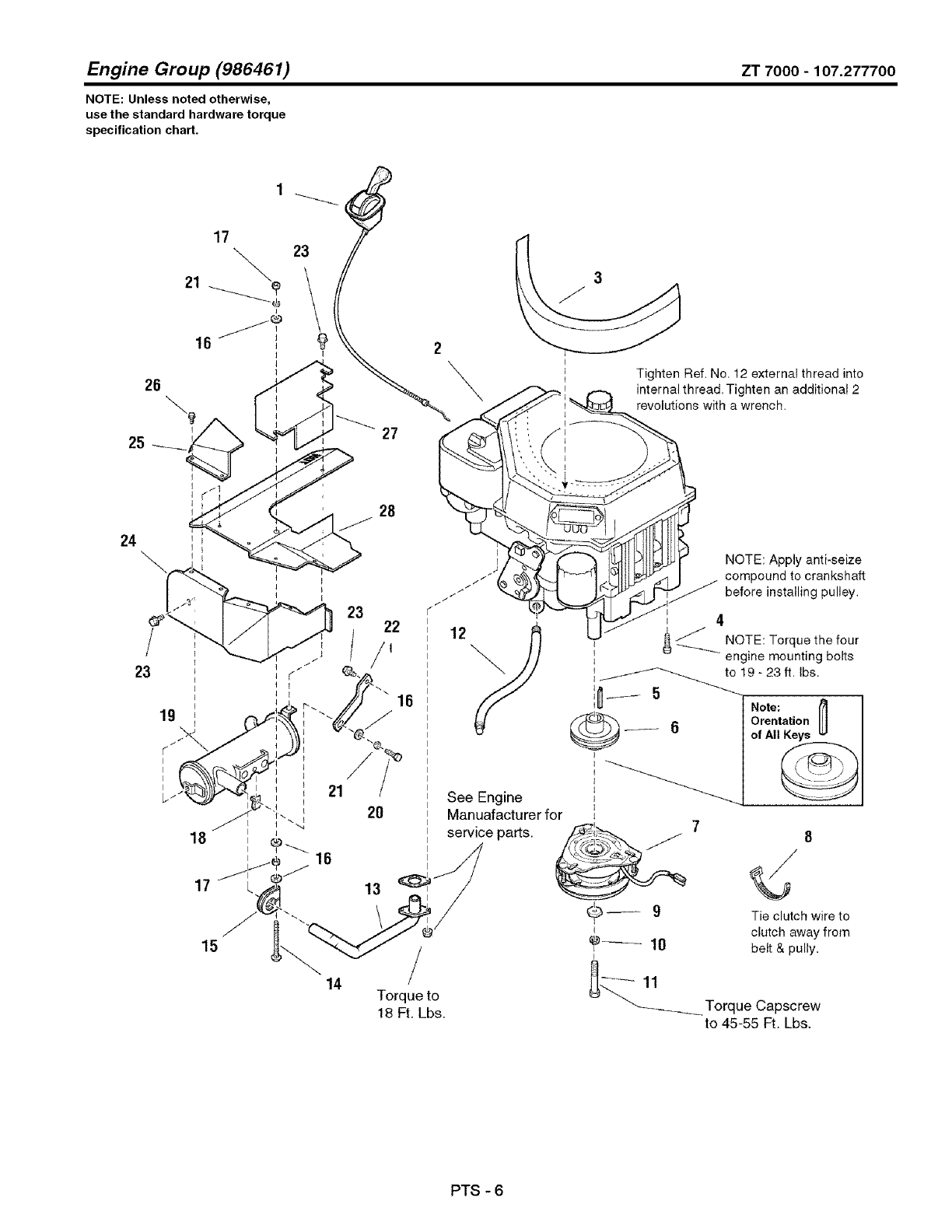
Engine Group (986461) ZT 7000 -107.277700
NOTE: Unless noted otherwise,
use the standard hardware torque
specification chart.
26
25
21
16
27
2\Tighten Ref. No. 12 external thread into
internal thread. Tighten an additional 2
revolutions with a wrench.
24
21
14
28
22
/,
16
2O See Engine
Manuafacturer for
service parts.
13
/
Torque to
18 Ft. Lbs.
NOTE: Apply anti-seize
compound to crankshaft
before installing pulley.
I
i 4
,f NOTE: Torque the fourt
_ engine mounting bolts
I
__j_-_-_ to 19- 23 ft. Ibs,
I
i
t
t
i7
_9
t
I
8
Tie clutch wire to
clutch away from
belt & pully.
"-_-..-.__ Torque Capscrew
to 45-55 Ft. Lbs.
PTS - 6
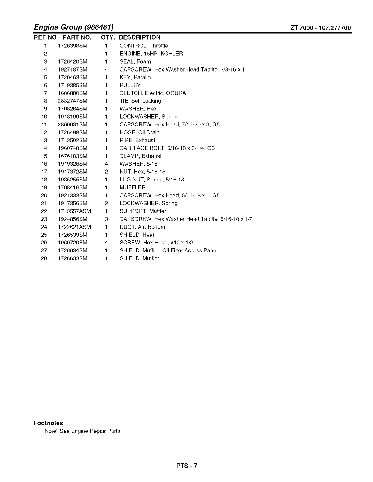
Engine Group (986461)
REF NO PART NO. QTY.
1 1726398SM 1
2 * 1
3 1726420SM 1
4 1927187SM 4
5 1720463SM 1
6 1719385SM 1
7 1686880SM 1
8 2832747SM 1
9 1708264SM 1
10 1918199SM 1
11 2860631SM 1
12 1726498SM 1
13 1713502SM 1
14 1960748SM 1
15 1676183SM 1
16 1919326SM 4
17 1917372SM 2
18 1935255SM 1
19 1708416SM 1
20 1921333SM 1
21 1917356SM 2
22 1713557ASM 1
23 1924856SM 3
24 1722621ASM 1
25 1726539SM 1
26 1960720SM 4
27 1726634SM 1
28 1726633SM 1
ZT 7000-107.277700
DESCRIPTION
CONTROL, Throttle
ENGINE, 18HP, KOHLER
SEAL, Foam
CAPSCREW, Hex Washer Head Taptite, 3/8-16 x 1
KEY, Parallel
PULLEY
CLUTCH, Electric, OGURA
TIE, Self Locking
WASHER, Hex
LOCKWASHER, Spring
CAPSCREW, Hex Head, 7/16-20 x 3, G5
HOSE, Oil Drain
PIPE, Exhaust
CARRIAGE BOLT, 5/16-18 x 3-1/4, G5
CLAMP, Exhaust
WASHER, 5/16
NUT, Hex, 5/16-18
LUG NUT, Speed, 5/16-18
MUFFLER
CAPSCREW, Hex Head, 5/16-18 x 1, G5
LOCKWASHER, Spring
SUPPORT, Muffler
CAPSCREW, Hex Washer Head Taptite, 5/16-18 x 1/2
DUCT, Air, Bottom
SHIELD, Heat
SCREW, Hex Head, #10x 1/2
SHIELD, Muffler, Oil Filter Access Panel
SHIELD, Muffler
Footnotes
Note* See Engine Repair Parts.
PTS - 7
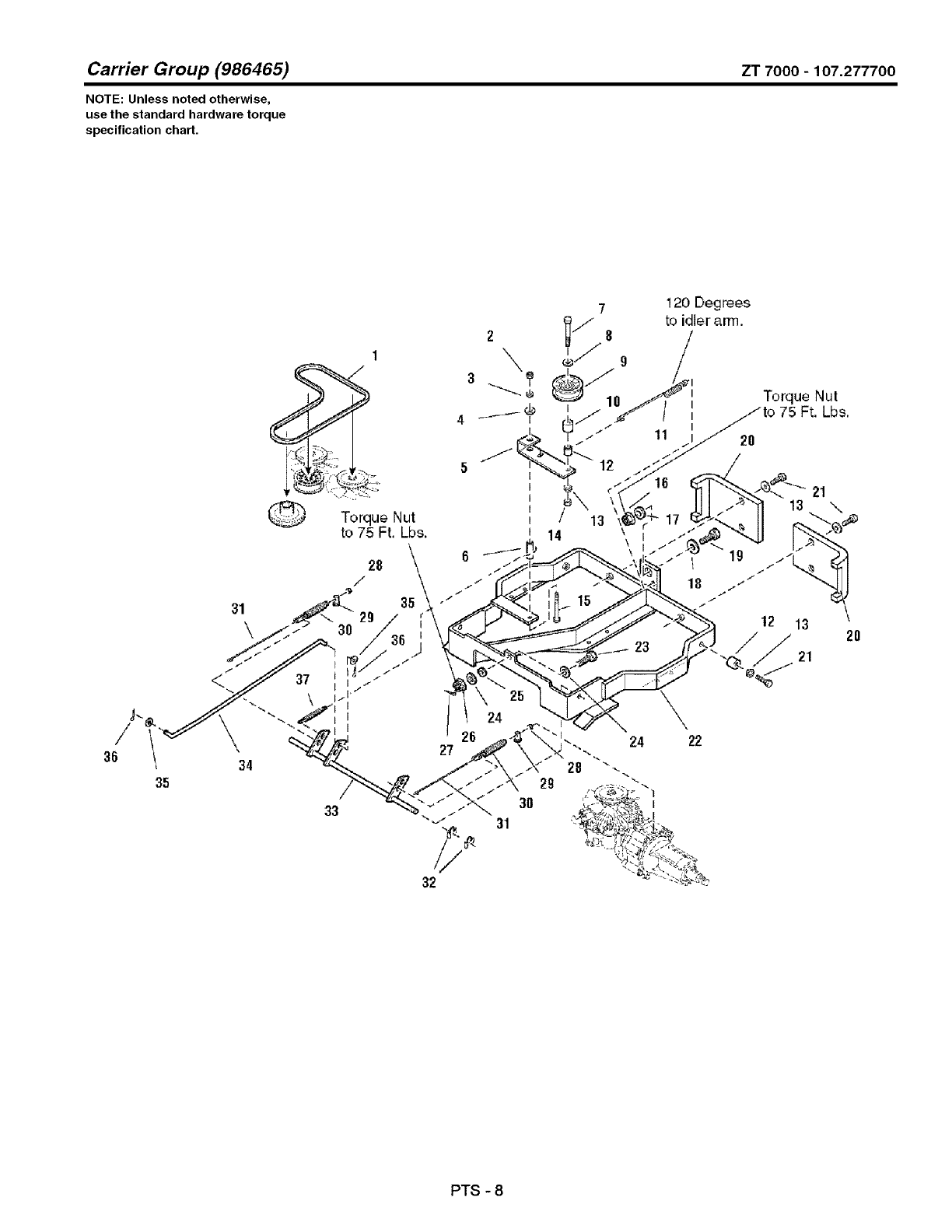
Carrier Group (986465) ZT 7000 - 107.277700
NOTE: Unless noted otherwise,
use the standard hardware torque
specification chart,
36
35
31
\
Torque Nut
to 75 Ft. Lbs.
28
/
35
29
30
34
33
120 Deg tees
to idleranm.
11
17
Torque Nut
75 Ft. Lbs,
2o
19 t _'_
18 .,.
I26
27
24
24 22
2O
32
31
3O
PTS - 8
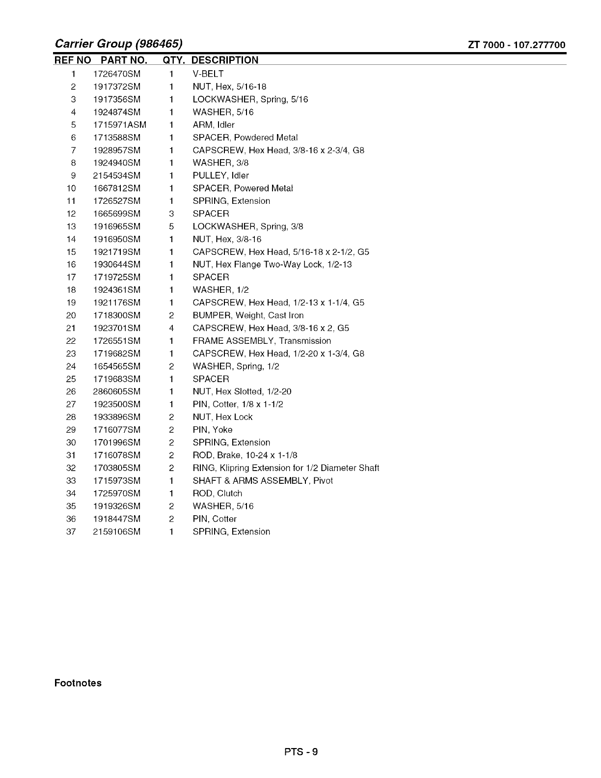
Carrier Group (986465)
REF NO PART NO, QTY,
1 1726470SM 1
2 1917372SM 1
3 1917356SM 1
4 1924874SM 1
5 1715971ASM 1
6 1713588SM 1
7 1928957SM 1
8 1924940SM 1
9 2154534SM 1
10 1667812SM 1
11 1726527SM 1
12 1665699SM 3
13 1916965SM 5
14 1916950SM 1
15 1921719SM 1
16 1930644SM 1
17 1719725SM 1
18 1924361SM 1
19 1921176SM 1
20 1718300SM 2
21 1923701SM 4
22 1726551SM 1
23 1719682SM 1
24 1654565SM 2
25 1719683SM 1
26 2860605SM 1
27 1923500SM 1
28 1933896SM 2
29 1716077SM 2
30 1701996SM 2
31 1716078SM 2
32 1703805SM 2
33 1715973SM 1
34 1725970SM 1
35 1919326SM 2
36 1918447SM 2
37 2159106SM 1
ZT 7000-107.277700
DESCRIPTION
V-BELT
NUT, Hex, 5/16-18
LOCKWASHER, Spring, 5/16
WASHER, 5/16
ARM, Idler
SPACER, Powdered Metal
CAPSCREW, Hex Head, 3/8-16 x 2-3/4, G8
WASHER, 3/8
PULLEY, Idler
SPACER, Powered Metal
SPRING, Extension
SPACER
LOCKWASHER, Spring, 3/8
NUT, Hex, 3/8-16
CAPSCREW, Hex Head, 5/16-18 x 2-1/2, G5
NUT, Hex Flange Two-Way Lock, 1/2-13
SPACER
WASHER, 1/2
CAPSCREW, Hex Head, 1/2-13 x 1-1/4, G5
BUMPER, Weight, Cast Iron
CAPSCREW, Hex Head, 3/8-16 x 2, G5
FRAME ASSEMBLY, Transmission
CAPSCREW, Hex Head, 1/2-20 x 1-3/4, G8
WASHER, Spring, 1/2
SPACER
NUT, Hex Slotted, 1/2-20
PIN, Cotter, 1/8 x 1-1/2
NUT, Hex Lock
PIN, Yoke
SPRING, Extension
ROD, Brake, 10-24 x 1-1/8
RING, Klipring Extension for 1/2 Diameter Shaft
SHAFT & ARMS ASSEMBLY, Pivot
ROD, Clutch
WASHER, 5/16
PIN, Cotter
SPRING, Extension
Footnotes
PTS - 9
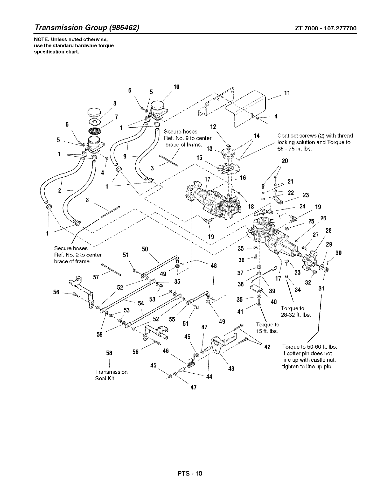
Transmission Group (986462) ZT 7000 -107.277700
NOTE: Unless noted otherwise,
use the standard hardware torque
specification chart.
59
58 56
I
Transmission
Seal Kit
37
l39
'-" 35 /_ 40
51 49 \
47 _Torque to
/'_ _15 ft. Ibs.
\42 Torque to 50-60 ft. Ibs.
"_'_ I" _ If cotter pin does not
_" line up with castle nut,
45 tighten to line up pin.
47
PTS - 10
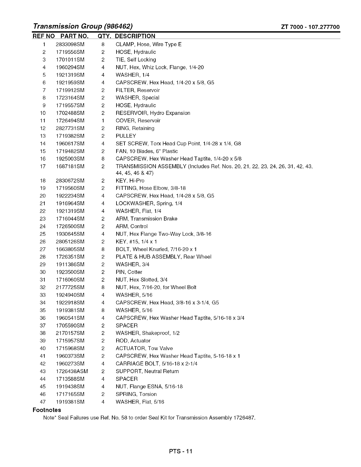
Transmission Group (986462) ZT 7000 -107.277700
REF NO PART NO. QTY.
1 2833098SM 8
2 1719556SM 2
3 1701011SM 2
4 1960294SM 4
5 1921319SM 4
6 1921959SM 4
7 1719912SM 2
8 1723164SM 2
9 1719557SM 2
10 1702488SM 2
11 1726494SM 1
12 2827731SM 2
13 1719382SM 2
14 1960617SM 4
15 1719482SM 2
16 1925003SM 8
17 1687181SM 2
DESCRIPTION
18 2830672SM
19 1719560SM
20 1922234SM
21 1916964SM
22 1921319SM
23 1716044SM
24 1726500SM
25 1930645SM
26 2805126SM
27 1663805SM
28 1726351SM
29 1911386SM
30 1923500SM
31 1716060SM
32 2177725SM
33 1924940SM
34 1922918SM
35 1919381SM
36 1960541SM
37 1705590SM
38 2170157SM
39 1715957SM
40 1715968SM
41 1960373SM
42 1960273SM
43 1726438ASM
44 1713588SM
45 1919438SM
46 1717165SM
47 1919381SM
Footnotes
Note* Seal Failures use
CLAMP, Hose, Wire Type E
HOSE, Hydraulic
TIE, Self Locking
NUT, Hex, Whiz Lock, Flange, 1/4-20
WASHER, 1/4
CAPSCREW, Hex Head, 1/4-20 x 5/8, G5
FILTER, Reservoir
WASHER, Special
HOSE, Hydraulic
RESERVOIR, Hydro Expansion
COVER, Reservoir
RING, Retaining
PULLEY
SET SCREW, Torx Head Cup Point, 1/4-28 x 1/4, G8
FAN, 10 Blades, 6" Plastic
CAPSCREW, Hex Washer Head Taptite, 1/4-20 x 5/8
TRANSMISSION ASSEMBLY (Includes Ref. Nos. 20, 21, 22, 23, 24, 26, 31,42, 43,
44, 45, 46 & 47)
2 KEY, Hi-Pro
2 FITTING, Hose Elbow, 3/8-18
4 CAPSCREW, Hex Head, 1/4-28 x 5/8, G5
4 LOCKWASHER, Spring, 1/4
4 WASHER, Flat, 1/4
2 ARM, Transmission Brake
2 ARM, Control
4 NUT, Hex Flange Two-Way Lock, 3/8-16
2 KEY, #15, 1/4 x 1
8 BOLT, Wheel Knurled, 7/16-20 x 1
2 PLATE & HUB ASSEMBLY, Rear Wheel
2 WASHER, 3/4
2 PIN, Cotter
2 NUT, Hex Slotted, 3/4
8 NUT, Hex, 7/16-20, for Wheel Bolt
4 WASHER, 5/16
4 CAPSCREW, Hex Head, 3/8-16 x 3-1/4, G5
8 WASHER, 5/16
4 CAPSCREW, Hex Washer Head Taptite, 5/16-18 x 3/4
2 SPACER
2 WASHER, Shakeproof, 1/2
2 ROD, Actuator
2 ACTUATOR, Tow Valve
2 CAPSCREW, Hex Washer Head Taptite, 5-16-18 x 1
4 CARRIAGE BOLT, 5/16-18 x 2-1/4
2 SUPPORT, Neutral Return
4 SPACER
4 NUT, Flange ESNA, 5/16-18
2 SPRING, Torsion
4 WASHER, Flat, 5/16
Ref. No. 58 to order Seal Kit for Transmission Assembly 1726487.
PTS - 11

Transmission Group (986462) ZT 7000 -107.277700
NOTE: Unless noted otherwise,
use the standard hardware torque
specification chart.
59
58 56
I
Transmission
Seal Kit
37
l39
'-" 35 /_ 40
51 49 \
47 _Torque to
/'_ _15 ft. Ibs.
\42 Torque to 50-60 ft. Ibs.
"_'_ I" _ If cotter pin does not
_" line up with castle nut,
45 tighten to line up pin.
47
PTS - 12

Transmission Group (986462)
REF NO PART NO. QTY.
49 1960027SM 2
50 1715958SM 1
51 1931335SM 2
52 1703900SM 4
53 1919438SM 4
54 1725945SM 2
55 1715959SM 1
56 1921333SM 2
57 1701011SM 1
58 1719442SM 1
59 1924874SM 2
ZT 7000-107.277700
DESCRIPTION
WASHER, 1/2
LINK, Control Rear, R.H.
CARRIAGE BOLT, 5/16-18 x 1, G5
SPACER
NUT, Hex ESNA Light Lock, 5/16-18
ROD, Control
LINK, Control Rear, L.H.
CAPSCREW, Hex Head, 5/16-18 x 1, G5
TIE, Self Locking
* SEAL KIT, Transmission
WASHER, 5/16
Footnotes
Note* Seal Failures use Ref. No. 58 to order Seal Kit for Transmission Assembly 1726487.
PTS - 13
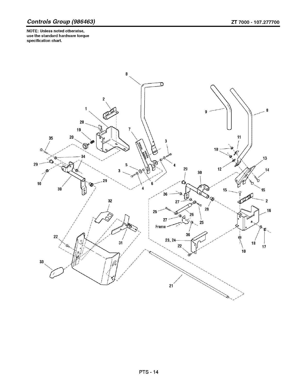
Controls Group (986463) ZT 7000 -107.277700
NOTE: Unless noted otherwise,
use the standard hardware torque
specification chad.
2
28
19
32
'i
!
33
429
I
6
f
Frame
/36
/23,
31 /
/22
l! i
Ili /
21
11
10 i
13
PTS - 14
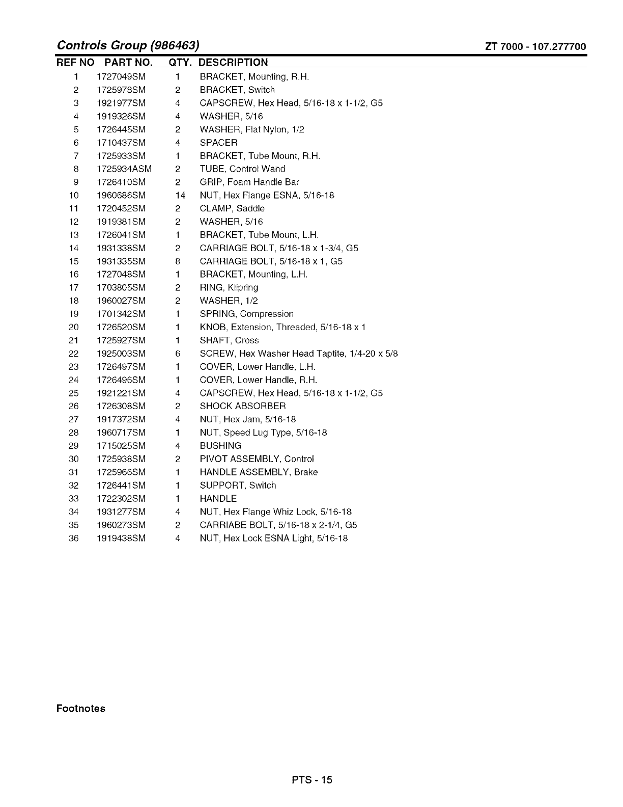
Controls Group (986463)
REF NO PART NO. QTY.
1 1727049SM 1
2 1725978SM 2
3 1921977SM 4
4 1919326SM 4
5 1726445SM 2
6 1710437SM 4
7 1725933SM 1
8 1725934ASM 2
9 1726410SM 2
10 1960686SM 14
11 1720452SM 2
12 1919381SM 2
13 1726041SM 1
14 1931338SM 2
15 1931335SM 8
16 1727048SM 1
17 1703805SM 2
18 1960027SM 2
19 1701342SM 1
20 1726520SM 1
21 1725927SM 1
22 1925003SM 6
23 1726497SM 1
24 1726496SM 1
25 1921221SM 4
26 1726308SM 2
27 1917372SM 4
28 1960717SM 1
29 1715025SM 4
30 1725938SM 2
31 1725966SM 1
32 1726441SM 1
33 1722302SM 1
34 1931277SM 4
35 1960273SM 2
36 1919438SM 4
ZT 7000-107.277700
DESCRIPTION
BRACKET, Mounting, R.H.
BRACKET, Switch
CAPSCREW, Hex Head, 5/16-18 x 1-1/2, G5
WASHER, 5/16
WASHER, Flat Nylon, 1/2
SPACER
BRACKET, Tube Mount, R.H.
TUBE, Control Wand
GRIP, Foam Handle Bar
NUT, Hex Flange ESNA, 5/16-18
CLAMP, Saddle
WASHER, 5/16
BRACKET, Tube Mount, L.H.
CARRIAGE BOLT, 5/16-18 x 1-3/4, G5
CARRIAGE BOLT, 5/16-18 x 1, G5
BRACKET, Mounting, L.H.
RING, Klipring
WASHER, 1/2
SPRING, Compression
KNOB, Extension, Threaded, 5/16-18 x 1
SHAFT, Cross
SCREW, Hex Washer Head Taptite, 1/4-20 x 5/8
COVER, Lower Handle, L.H.
COVER, Lower Handle, R.H.
CAPSCREW, Hex Head, 5/16-18 x 1-1/2, G5
SHOCK ABSORBER
NUT, Hex Jam, 5/16-18
NUT, Speed Lug Type, 5/16-18
BUSHING
PIVOT ASSEMBLY, Control
HANDLE ASSEMBLY, Brake
SUPPORT, Switch
HANDLE
NUT, Hex Flange Whiz Lock, 5/16-18
CARRIABE BOLT, 5/16-18 x 2-1/4, G5
NUT, Hex Lock ESNA Light, 5/16-18
Footnotes
PTS - 15
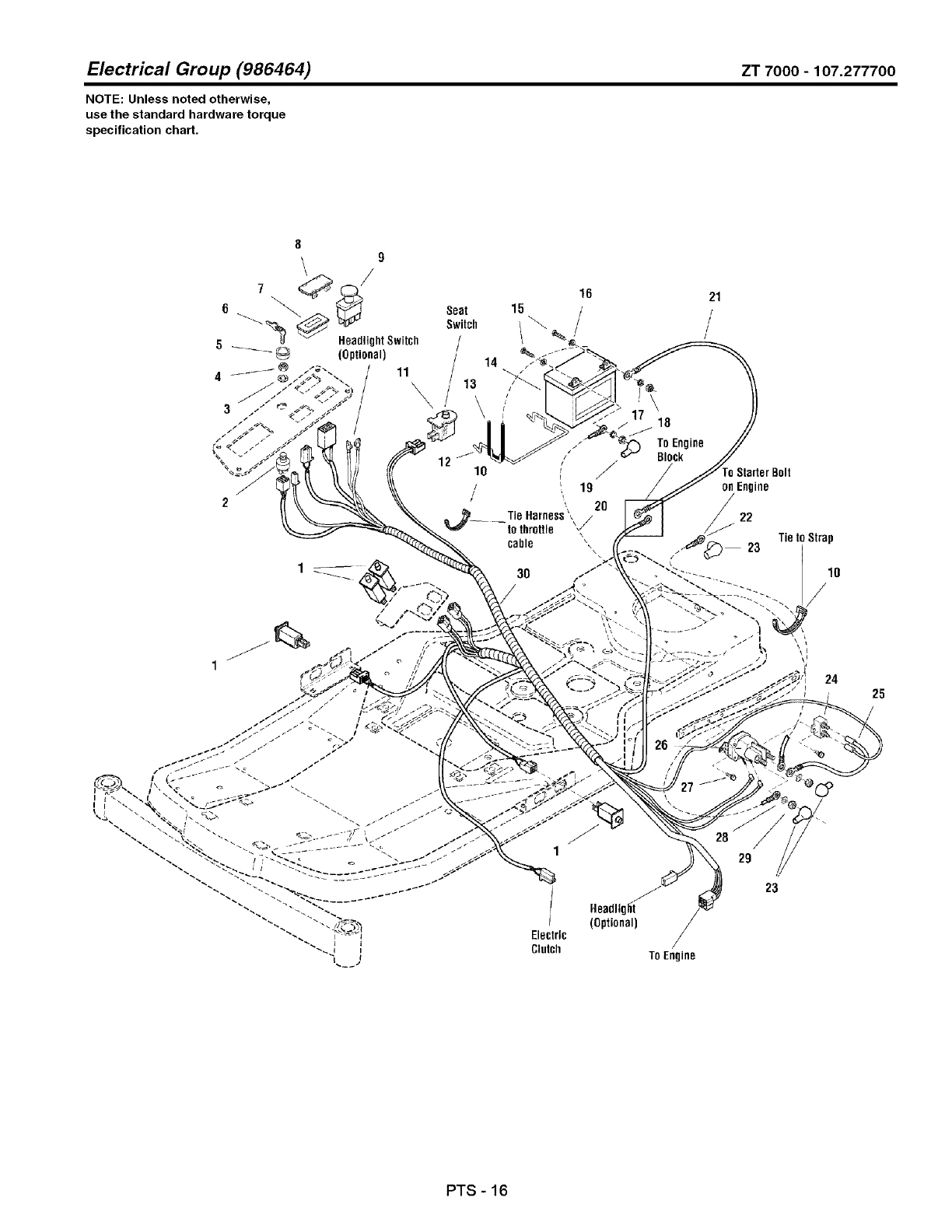
Electrical Group (986464) ZT 7000 -107.277700
NOTE: Unless noted otherwise,
use the standard hardware torque
specification chart.
Seat
Switch
/
/
/
11 /
16
15 /
14
{
\i
3O
Headlig_i
/ (Optional)
Electric
Clutch
18
ToEngine
Block
TO Engine
21
/
/
/
on Engine
22
24
27
28
29
23
25
PTS - 16
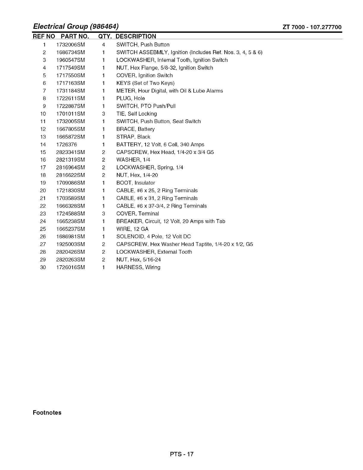
Electrical Group (986464)
REF NO PART NO. QTY.
1 1732006SM 4
2 1686734SM 1
3 1960547SM 1
4 1717549SM 1
5 1717550SM 1
6 1717163SM 1
7 1731184SM 1
8 1722611SM 1
9 1722887SM 1
10 1701011SM 3
11 1732005SM 1
12 1667805SM 1
13 1665872SM 1
14 1726376 1
15 2823341SM 2
16 2821319SM 2
17 2816964SM 2
18 2816622SM 2
19 1709086SM 1
20 1721830SM 1
21 1703589SM 1
22 1666328SM 1
23 1724588SM 3
24 1665238SM 1
25 1665237SM 1
26 1686981SM 1
27 1925003SM 2
28 2820426SM 2
29 2820263SM 2
30 1726016SM 1
ZT 7000-107.277700
DESCRIPTION
SWITCH, Push Button
SWITCH ASSEBMLY, Ignition (Includes Ref. Nos. 3, 4, 5 & 6)
LOCKWASHER, Internal Tooth, Ignition Switch
NUT, Hex Flange, 5/8-32, Ignition Switch
COVER, Ignition Switch
KEYS (Set of Two Keys)
METER, Hour Digital, with Oil & Lube Alarms
PLUG, Hole
SWITCH, PTO Push/Pull
TIE, Self Locking
SWITCH, Push Button, Seat Switch
BRACE, Battery
STRAP, Black
BATTERY, 12 Volt, 6 Cell, 340 Amps
CAPSCREW, Hex Head, 1/4-20 x 3/4 G5
WASHER, 1/4
LOCKWASHER, Spring, 1/4
NUT, Hex, 1/4-20
BOOT, Insulator
CABLE, #6 x 25, 2 Ring Terminals
CABLE, #6 x 31, 2 Ring Terminals
CABLE, #6 x 37-3/4, 2 Ring Terminals
COVER, Terminal
BREAKER, Circuit, 12 Volt, 20 Amps with Tab
WIRE, 12 GA
SOLENOID, 4 Pole, 12 Volt DC
CAPSCREW, Hex Washer Head Taptite, 1/4-20 x 1/2, G5
LOCKWASHER, External Tooth
NUT, Hex, 5/16-24
HARNESS, Wiring
Footnotes
PTS - 17
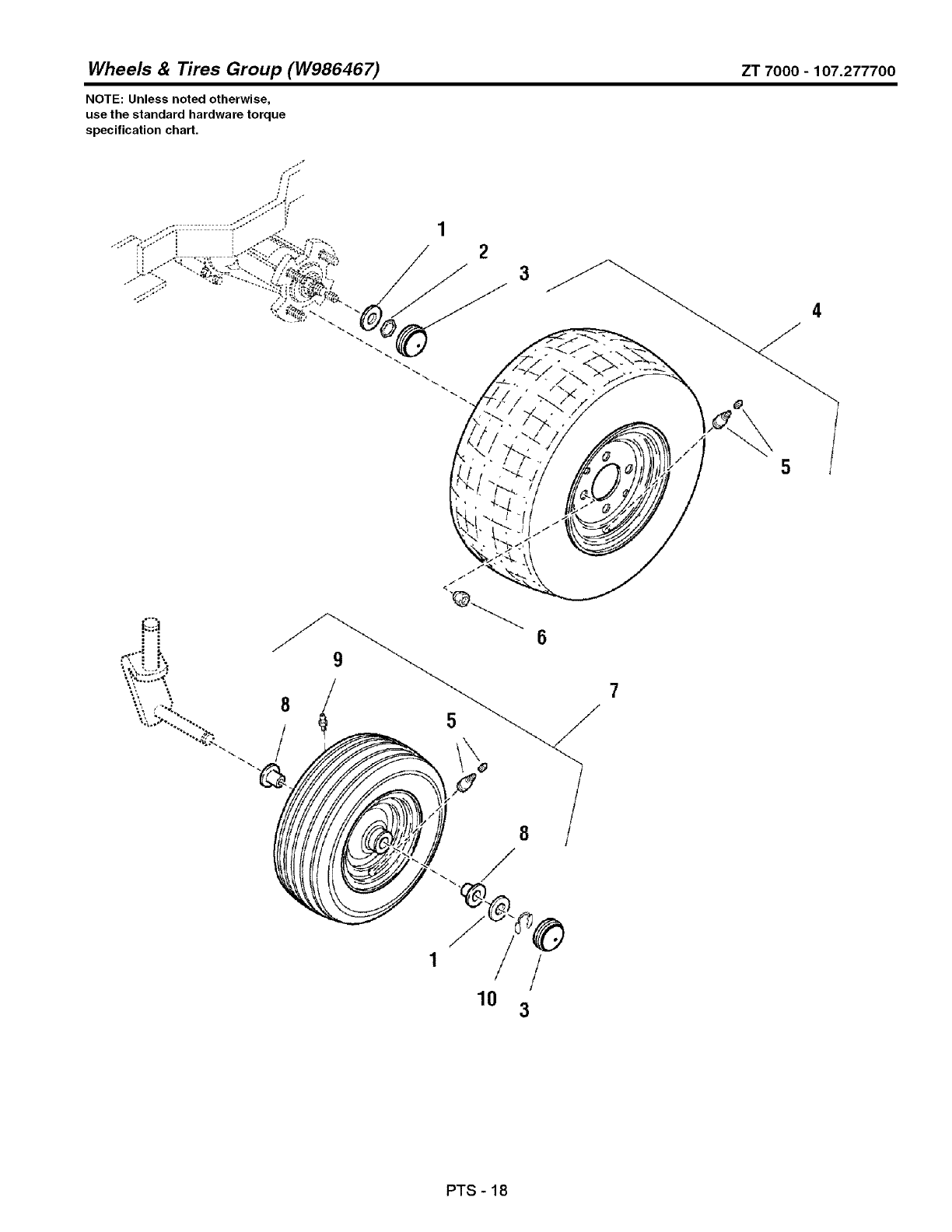
Wheels & Tires Group (W986467) ZT 7000 - 107.277700
NOTE: Unless noted otherwise,
use the standard hardware torque
specification chart,
3
'X.>'... "...
•-,".:.< -..
%%
1
10 3
PTS-18

Wheels & Tires Group (W986467)
REF NO PART NO. QTY. DESCRIPTION
1 2860202SM 4
2 1716099SM 2
3 1722675SM 4
4 1726383SM 2
5 2172353SM 2
6 2177725SM 8
7 1726382SM 2
8 1713167SM 4
9 2812808SM 2
10 1611710SM 2
ZT 7000-107.277700
WASHER, 3/4
NUT, Hex Lock PAL, 3/4-20
CAP, Hub
WHEEL & TIRE ASSEMBLY, Rear
VALVE STEM & CAP
NUT, Hex Lug, 7/16-20
WHEEL & TIRE ASSEMBLY, Front
BUSHING, Wheel
FITTING, Lube
RING, Klipring for 3/4 Shaft
Footnotes
PTS - 19
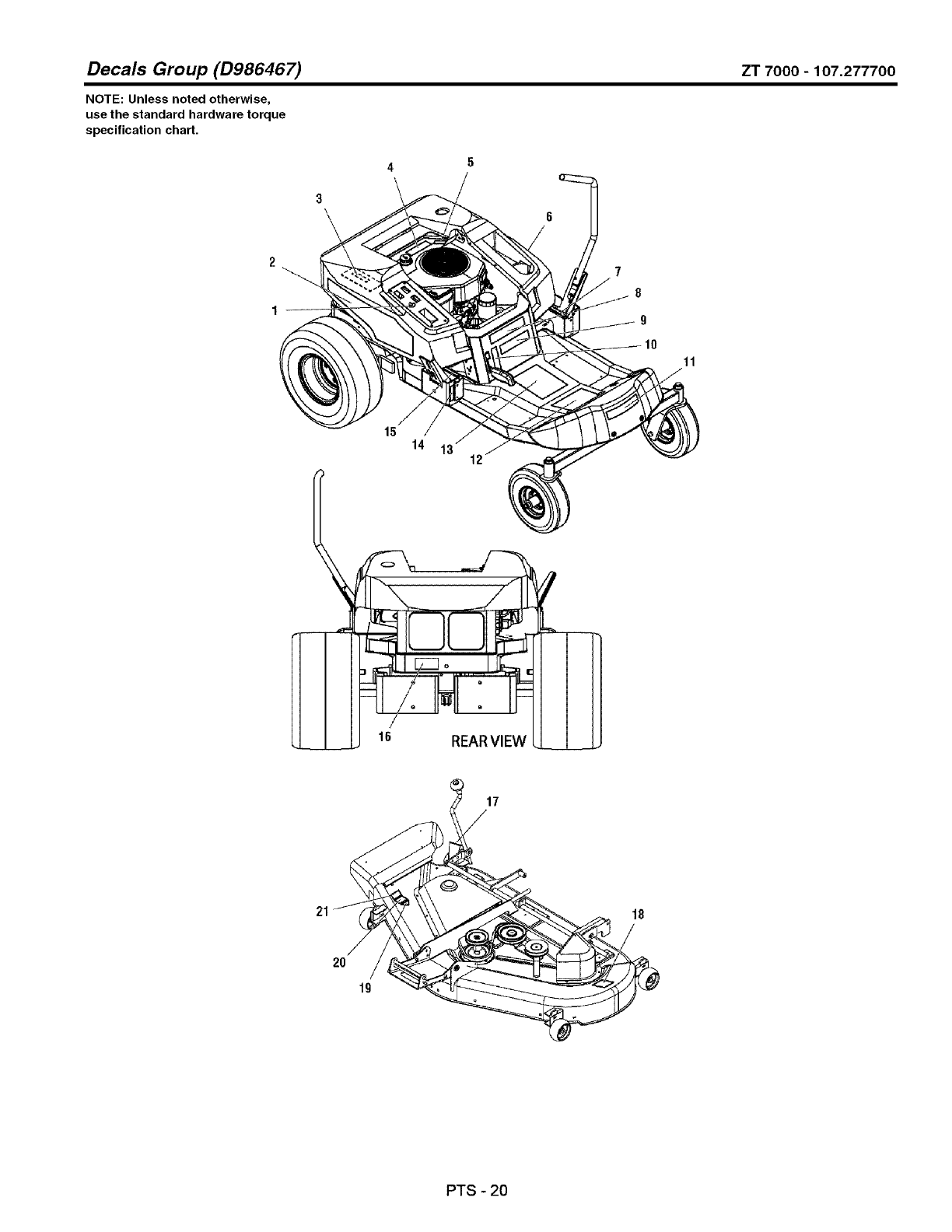
Decals Group (D986467) ZT 7000 - 107.277700
NOTE: Unless noted otherwise,
use the standard hardware torque
specification chart.
2
3\
4\
7
8
g
15
14 13 12
17
2O
19
PTS - 20

Decals
REF NO
1 1726526SM
2 1726523SM
3 1726525SM
4 1726389SM
5 1726631SM
6 1726522SM
7 1725671SM
8 1726524SM
9 1726630SM
10 1726529SM
11 1726521SM
12 1726429SM
13 1726430SM
14 1726638SM
15 1725670SM
16 1715996SM
17 1721197SM
18 1704276SM
19 *
20 1722790SM
21 1704277SM
Group (D986467)
PART NO. QTY. DESCRIPTION
1
1
1
1
1
1
1
1
1
1
1
1
1
1
1
1
1
1
1
1
1
DECAL
DECAL
DECAL
DECAL
DECAL
DECAL
DECAL
DECAL
DECAL
DECAL
DECAL
DECAL
DECAL
DECAL
DECAL
DECAL
DECAL
DECAL
DECAL
DECAL
DECAL
Ignition Switch
Hood Stripe, R.H.
Sealed Hydraulic System
Engine 18HP Kohler
Do Not Remove Foam Seal
Hood Stripe, L.H.
Speed Control, L.H.
18 Model ZT 7000
ZT 7000
Parking Brake
CRAFTSMAN
Panel Upper, Operation
Panel Lower, Warning/Danger & Icon Indicator
Tracking
Speed Control, R.H.
Transmission Release Valve
Height of Cut
Danger (Do Not Put Hands/Feet in Mower)
OPEl Certified (Not Serviced)
50"
Danger (Do Not Operate With Out Deflector)
ZT 7000-107.277700
Footnotes
Note* Not a Service Part.
PTS - 21
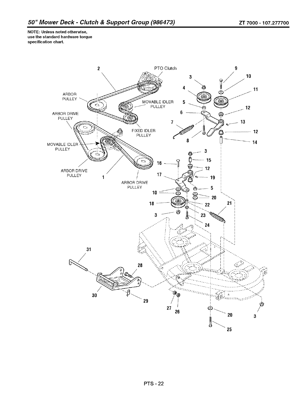
50" Mower Deck -Clutch & Support Group (986473) ZT 7000 -107.277700
NOTE: Unless noted otherwise,
use the standard hardware torque
specification chart.
2
\\
PTO Clutch
ARBOR
PULLEY MOVABLE IDLER 5
PULLEY
6
/
1
ARBOR DRIVE
PULLEY
31
-/
9
3 10
11
/
29
I
I
I
I
] }
27 26 _
I20 3
25
PTS - 22
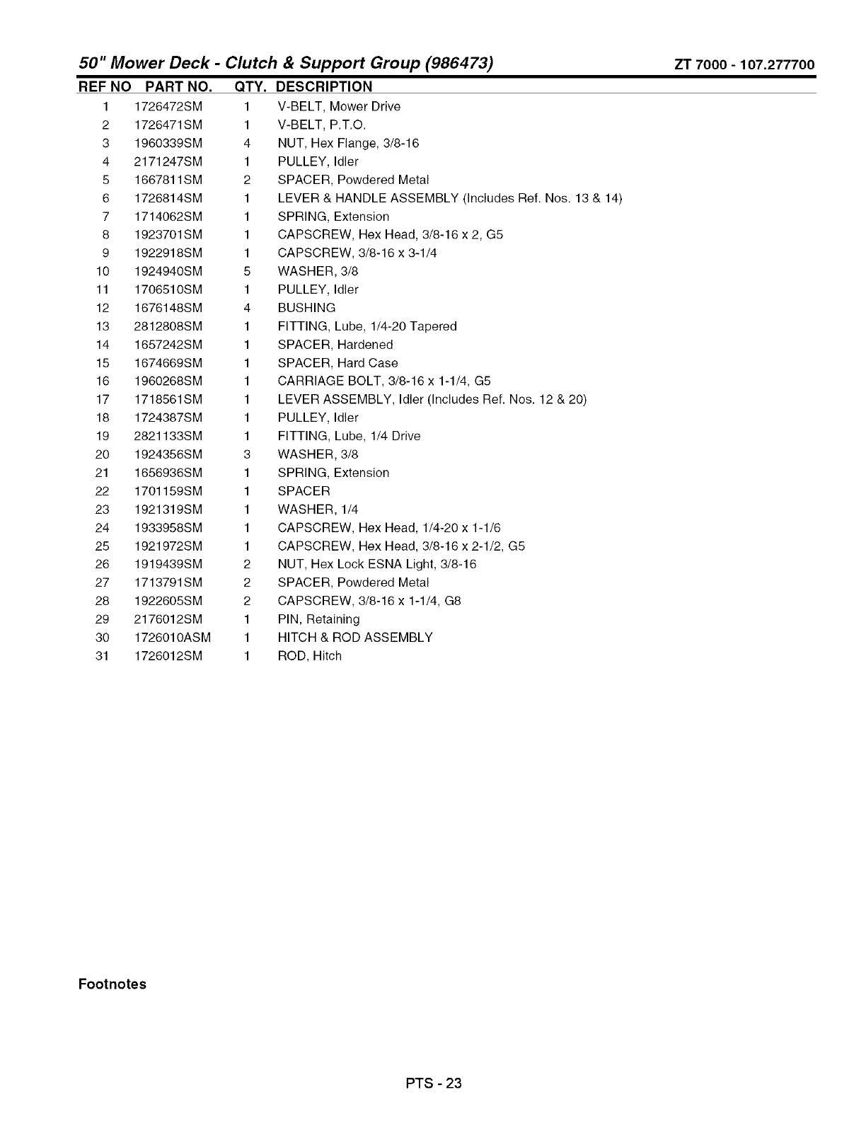
& Support Group (986473) ZT 7000 -107.277700
50" Mower Deck -Clutch
REF NO PART NO. QTY.
1 1726472SM 1
2 1726471SM 1
3 1960339SM 4
4 2171247SM 1
5 1667811SM 2
6 1726814SM 1
7 1714062SM 1
8 1923701SM 1
9 1922918SM 1
10 1924940SM 5
11 1706510SM 1
12 1676148SM 4
13 2812808SM 1
14 1657242SM 1
15 1674669SM 1
16 1960268SM 1
17 1718561SM 1
18 1724387SM 1
19 2821133SM 1
20 1924356SM 3
21 1656936SM 1
22 1701159SM 1
23 1921319SM 1
24 1933958SM 1
25 1921972SM 1
26 1919439SM 2
27 1713791SM 2
28 1922605SM 2
29 2176012SM 1
30 1726010ASM 1
31 1726012SM 1
DESCRIPTION
V-BELT, Mower Drive
V-BELT, P.T.O.
NUT, Hex Flange, 3/8-16
PULLEY, Idler
SPACER, Powdered Metal
LEVER & HANDLE ASSEMBLY (Includes Ref. Nos. 13 & 14)
SPRING, Extension
CAPSCREW, Hex Head, 3/8-16 x 2, G5
CAPSCREW, 3/8-16 x 3-1/4
WASHER, 3/8
PULLEY, Idler
BUSHING
FITTING, Lube, 1/4-20 Tapered
SPACER, Hardened
SPACER, Hard Case
CARRIAGE BOLT, 3/8-16 x 1-1/4, G5
LEVER ASSEMBLY, Idler (Includes Ref. Nos. 12 & 20)
PULLEY, Idler
FITTING, Lube, 1/4 Drive
WASHER, 3/8
SPRING, Extension
SPACER
WASHER, 1/4
CAPSCREW, Hex Head, 1/4-20 x 1-1/6
CAPSCREW, Hex Head, 3/8-16 x 2-1/2, G5
NUT, Hex Lock ESNA Light, 3/8-16
SPACER, Powdered Metal
CAPSCREW, 3/8-16 x 1-1/4, G8
PIN, Retaining
HITCH & ROD ASSEMBLY
ROD, Hitch
Footnotes
PTS - 23

50" Mower Deck -Height Adjustment Group (986471) ZT 7000 -107.277700
NOTE: Unless noted otherwise,
use the standard hardware torque
specification chart,
19
43 42
20
21
22
24 2120
25
28
26
27
PTS - 24

50" Mower Deck -Height Adjustment Group (986471)
REF NO
1
2
3
4
5
6
7
8
9
lO
11
12
13
14
15
16
18
19
2o
21
22
23
24
25
26
27
28
29
30
31
32
33
34
35
36
37
38
39
40
41
42
43
44
ZT 7000-107.277700
PART NO.
1931202SM
1919381SM
1704114SM
1726424ASM
1724009SM
1704097SM
2816001SM
1960170SM
1715892SM
1704314SM
1727681SM
1714084SM
1960093SM
1921977SM
1704116ASM
1726409ASM
1931277SM
1726007ASM
1921210SM
1916965SM
1716010SM
1960655SM
1718136ASM
1714879SM
1924874SM
2860643SM
1664847SM
1665374SM
1960373SM
2118053SM
1960074SM
1960716SM
1924366SM
1706645ASM
1930642SM
1716020ASM
1923341SM
1714760SM
1960027SM
2158399SM
1717152SM
1918451SM
1709195SM
QTY. DESCRIPTION
2 CAPSCREW, Hex Washer Head Taptite, 5/16-18 x 1-1/4
1 WASHER, 5/16
1 ROD, Indicator Height of Cut
1 PLATE & BRACKET ASSEMBLY, Gauge Wheel
1 TRUNNION, 1-1/4
1 WASHER, Detent
1 PIN, Spring
2 WASHER, 9/16
1 TRUNNION, 1-1/4
1 FITTING, Lube
1 CRANK, Height Adjustment
1 KNOB, Spinner, Soft
1 NUT, Push
2 CAPSCREW, Hex Head, 5/16-18 x 1-1/4, G5
1 BRACKET, Height of Cut
1 ARM, Rear
2 NUT, Hex, 5/16-18
1 ARM ASSEMBLY, Roller Bar
2 CAPSCREW, Hex Head, 3/8-16 x 1, G5
2 LOCKWASHER, Spring, 3/8
2 SPACER, Support
1 CARRIAGE BOLT, 5/16-18 x 1-1/4, G5
1 ARM, Rear Adjustable
1 CAM, Eccentric, Hex
1 WASHER, 5/16
1 NUT, Hex Flange Collar Lock, 5/16-18
6 CAPSCREW, Hex Washer Head Taptite, 5/16-18 x 3/4
3 STRAP, Arm Assembly
1 CAPSCREW, Hex Washer Head Taptite, 5/16-18 x 1
1 PIN, Round Head, Drilled, 3/8 x 2
1 PIN, Hair, 3/32
2 NUT, Hex Jam, 5/8-11
2 WASHER, 5/8
1 TRUNNION
4 NUT, Hex Flange Toplock 1/4-20
4 SHAFT & BAR ASSEMBLY, Roller Fixed Arm
4 CAPSCREW, Hex Head, 1/4-20 x 3/4, G5
4 WHEEL, Roller
4 WASHER, 1/2
4 E-RING, Retaining Extenstion
1 ROD, Pitch
1 PIN, Cotter, 1/8 x 3/8
1 SPACER
Footnotes
PTS - 25

50" Mower Deck -Housing & Arbor Group (986468) ZT 7000 -107.277700
NOTE: Unless noted otherwise,
use the standard hardware torque
specification chart.
41
2
3
I
I
I
18
17
2O
2O 27 21
Torque Capscrews
to 45-55 Ft. Lbs, or
61-75 NM.
22
....... 23
24
25
PTS - 26

50" Mower Deck -Housing & Arbor Group (986468)
REF NO
1
2
3
4
5
6
7
8
9
lO
11
12
13
14
15
16
17
18
19
2o
21
22
23
24
25
26
27
28
29
30
31
32
33
34
35
36
37
38
39
40
41
42
43
44
ZT 7000-107.277700
PART NO.
1714419SM
1713675SM
1720387SM
1713158SM
1713098SM
1713533SM
1713197SM
1655729ASM
2108202SM
1715724SM
1732544SM
1707335SM
1705897SM
1713338ASM
1704314SM
1720560ASM
1664847SM
1687037SM
1713619SM
1713195SM
1713196SM
1726453ASM
1713089SM
1656916SM
2823471SM
1726357ASM
1713612SM
1931333SM
1724538ASM
1927557SM
1931318SM
1703601SM
1960518SM
1960353SM
1704873SM
1919326SM
1916964SM
1916622SM
1723938SM
1705115SM
1705449SM
1960633SM
1706709A
1920397SM
QTY. DESCRIPTION
3 NUT, Hex Flange Non-Locking, 9/16-18
6 WASHER, Belleville
1 PULLEY
1 HUB, Spacer, 2-13/32
3 PULLEY
1 HUB, 35/64
2 HUB, Serated, 35/64
3 HOUSING, Arbor Top
3 BEARING, Ball
3 SPACER, Bearing Sleeve
3 SPACER, Tube
3 GASKET, Foam
3 BEARING, Ball
3 HOUSING ASSEMBLY, Arbor Bottom, w/Lube Fitting
3 FITTING, Lube, 1/4 Drive
1 COVER, Arbor
27 CAPSCREW, Hex Washer Head Taptite, 5/16-18 x 3/4, G5
1 HOUSING ASSEMBLY, Mower Deck
3 WASHER, Cup
2 SHAFT, Arbor with Extruded Washers (short)
3 SHIELD, Grass, Lower Arbor
2 BLADE, Mower, Center & L.H.
3 WASHER, Hex
3 WASHER, Spring, 3/8
3 CAPSCREW, Hex Head, 7/16-14 x 1-1/4, G8
1 BLADE, Mower, R.H. (High Lift)
1 SHAFT, Arbor with Extruded Washers (Long)
2 CARRIAGE BOLT, 5/16-18 x 3/4, G5
1 BAFFLE, Blowout
2 NUT, Hex Flange Whiz Lock, 5/16-18
2 CARRIAGE BOLT, 1/4-20 x 7/8, G5
1 COVER, Arbor
2 NUT, Push
2 WASHER, 1/4
1 CLAMP, Wire
1 WASHER, 5/16
2 LOCKWASHER, Spring, 1/4
2 NUT, Hex, 1/4-20
1 Sting, Torsion
1 PLUG, Button
1 DEFLECTOR, Discharge
1 CARRIAGE BOLT, 1/4-20 x 1-1/2, G5
1 ROD, Deflector
1 NUT, Hex Lock ESNA Light, 1/4-20 NC-B3
Footnotes
PTS - 27

Engine Parts ZT 7000-Model No. 107.277700
Group 1 I
Crankshaft
Group 3
Oil Pan/Lubrication
m
3" II
0--4
13 \
/
29 14
1
/
@Group 2
Crankcase
2
12
\\
10
26
18
Group 4
Head/Valve/Breather
10
\
PTS -28

Engine Parts ZT 7000 -Model No. 107.277700
REF NO. PART NO. QTY. DESCRiPTiON DESCRiPTiON
CRANKSHAFT - Group 1
1 12 014 57-S 1 Crankshaft (Includes 2)
2 25 139 27-S 1 Plug, cup
CRANKCASE - Group 2
1 12 032 03-S 1 Seal, crankshaft
2 1 Crankcase (Use: Short
Block 12 522 69)
3 12 445 02-S 1 Strap, lifting
4 M-839025-S 1 Screw, hex. flange
M8x1.25x25
5 24 380 13-S 4 Pin, locating
6 12 010 31-S 1 Camshaft (Includes 7)
7 12 089 31-S 1 Spring, actuating
8 12 422 08-S (A.R.) Shim, camshaft - blue
12 422 09-S (A.R.) Shim, camshaft - red
12 422 10-S (A.R.) Shim, camshaft - yellow
12 422 11-S (A.R.) Shim, camshaft - green
12 422 12-S (A.R.) Shim, camshaft - gray
12 422 13-S (A.R.) Shim, camshaft - black
12 422 07-S 1 Shim, camshaft - white
9 12 144 28-S 1 Shaft, balance
10 12 874 07-S 1 Piston w/Ring Set (Std.)
(Includes 11, 12)
12 874 11-S 1 Piston w/Ring Set (.08)
12 874 08-S 1 Piston w/Ring Set (.25)
12 874 09-S 1 Piston w/Ring Set (.50)
11 12 018 02-S 2 Retainer, piston pin
12 12 108 07-S 1 Ring Set (Std. & .08)
12 108 08-S 1 Ring Set (.25)
12 108 09-S 1 Ring Set (.50)
13 12 067 11-S 1 Connecting Rod (Std.)
12 067 12-S 1 Connecting Rod (.25)
14 12 380 01-S 1 Pin, governor regulating
15 12 043 05-S 1 Gear, governor
16 M-631005-S 1 Washer, plain 6 mm
17 12 144 02-S 1 Shaft, governor gear
18 52 139 09-S 1 Plug, cup
19 12 755 64-S 1 Kit, governor cross shaft
w/clip (Includes 23)
20 X-25-102-S 1 Washer, plain 1/4"
21 12 032 01-S 1 Seal, governor cross shaft
22 M-631015-S 1 Washer, plain 6 mm
23 12 154 05-S 1 Clip, hitch pin
OiL PAN/LUBRICATION - Group 3
12 038 01-S
25 755 13-S
25 153 02-S
12 153 02-S
12 123 04-S
M-645025-S
1
2
3
4
5
6
7 12 153 01-S
8 25 162 07-S
9 12 096 03-S
10 M-545016-S
11 12 199 56-S
12 25 462 09-S
14 25 139 57-S
15 52 050 02-S
16 M-545016-S
1
1
1
1
1
1
1
1
1
1
1
1
1
3
17 12 096 34-S
18 12 153 06-S
REF NO. PART NO. QTY.
19 12 393 01-S 1
20 12 032 03-S 1
21 24086 16-S 11
22 24 086 17-S 1
Pump assembly, oil
Seal, oil (RT.O. end)
Screw, hex. flange
M8x1.25x45
Screw, hex. flange
M8x1.25x45
HEAD/VALVE/BREATHER - Group 4
1 25 351 01-S 2 Lifter, valve
2 24 755 101-S 1 Kit, cylinder head (Includes
3-16, carburetor gasket
(2),
3 12411 05-S
4 12 041 10-S
5 12 017 01-S
6 12 016 01-S
7 12 318 51-S
8 25 186 01-S
9 12 599 03-S
10 M-640034-S
11 12 089 34-S
12 12 173 01-S
13 12 755 03-S
14 12 468 05-S
15 12 112 13-S
16 20 086 02-S
17 25 237 14-S
18 12 326 18-S
19 M-645016-S
20 12 096 47-S
21 M-545010-S
22 66 018 04-S
23 12 402 02-S
NOT iLLUSTRATED
12 017 02-S
12 016 02-S
12 041 01-S
12 041 02-S
12 041 03-S
2
1
1
1
1
2
2
2
2
2
2
1
1
2
1
5
Rod, push
Gasket, cylinder head
Valve, intake (Std.)
Valve, exhaust (Std.)
Cylinder Head
Arm, rocker
Pivot, rocker arm
Screw, hex. flange
M6x1.0x34
Spring, valve
Cap, valve spring
Kit, retainer
Washer, plain 13/32"
Spacer, head bolt exhaust
port
Screw, hex. flange
M10x1.5x81
Clamp, hose
Hose, breather
Screw, hex. flange
M6x1.0x16
Cover, valve w/nipple
Screw, hex. flange
M5x0.8xl0
Retainer, breather reed
Reed, breather
Dipstick (Includes 2, 3)
Kit, oil fill cap (Includes 3)
O-Ring
O-Ring, upper oil fill tube
Tube, oil fill
Screw, hex. flange
M6x1.0x25
O-Ring, lower oil fill tube
Screen, oil pickup
Cover, oil pickup screen
Screw, hex. flange
M5x0.8x16
Pan assembly, oil (Includes
12, 23-26)
Valve, oil pressure relief
Plug, sq. hd. solid 3/8"
Filter, oil
Screw, hex. flange
M5x0.8x16
Cover, oil pump
O-Ring, oil pump cover PTS -29
1
1
2
1
1
Valve, intake (.25)
Valve, exhaust (.25)
Gasket, carburetor
Gasket, air cleaner base
Gasket, exhaust manifold

Engine Parts ZT 7000 =Model No. 107.277700
Group 5
Ignition/Electrical _fl
17
20 18j\
19 j5
9 10
12
_>\18 _ 14
Group 7
1 Starting System
2
&
3
13
Group 6
Blower Housing & Baffles
1 3 4 5
6
12
@
\9
Group 8
Fuel System
8
/19
5
/
3
17
16
7
/
1
PTS -30

Engine Parts ZT 7000 - Model No. 107.277700
REF NO. PART NO. QTY.
IGNITION/ELECTRICAL - Group 5
1 12 086 14-S
2 12 468 03-S
3 24 018 03-S
4 24 162 03-S
5 25 086 47-S
6 12 157 06-S
7 X-42-15-S
8 12 025 15-S
9 41 403 09-S
10 X-22-11-S
11 12 086 42-S
12 236602-S
13 12 154 06-S
14 M-548025-S
15 237878-S
16 41 155 02-S
17 M-545010-S
18 X-728-1 -S
19 12 132 02-S
20 12 584-04-S
21 M-545020-S
NOT iLLUSTRATED
25 518 05-3
12 518 01-S
24 518 12-S
DESCRIPT|ON
1 Screw, hex. flange
M10x1.5x46
1 Washer, plain 3/8"
3 Retainer, grass screen
1 Screen, grass
4 Bolt, shoulder
1 Fan
1 Key
1 Flywheel
1 Rectifier-regulator
1 Washer, lock 1/4"
2 Screw, tapping
1 Connector, rectifier-regula-
tor (3 contact)
2 Clip, rectifier-regulator
2 Screw, hex. cap MSx0.Sx25
1 Kit, starer (Includes
Terminal 25 452 01-S)
1 Connector (5 contact)
2 Screw, hex. flange
M5x0.8xl0
2 Clip
1 Spark Plug
1 Module, ignition
2 Screw, hex. flange
MSx0.8x20
Lead, black, rectifier to
connector (5" - 14 gauge
- uninsulated push on tab
terminals)
Lead, white, ground to ki_
(19" - 18 gauge - fully
insulated push on tab and
uninsulated push on tab
terminals)
Lead, black (6" - 12 gauge
- insulated grip barrel
eyelet terminals)
SLOWER HOUSING & BAFFLES
1 M-545010-S 5
2
3
4
24 468 10-S
12 146 07-S
M-645016-S
1
1
1
5 M-550010-S 1
6 24 096 05-S 1
7 12 027 55-S 1
8 12 063 18-S 1
9 M-541050-S 1
10 25 154 02-S 3
11 12 086 37-S 3
12 12 063 20-S 1
13 12 063 19-S 1
NOT iLLUSTRATED
12 113 119-S 1
- Group 6
Screw, hex. flange
M5x0.8xl0
Washer, plain 1/4"
Plate, blower housing
Screw, hex. flange
M6x1.0x16
Screw, hex. flange
MSx0.Sxl0
Cover, pinion
Housing, blower
Baffle, intake side
Nut, hex. flange M5x0.8
Clip, mounting
Screw
Baffle, cylinder head
Baffle, cylinder
Decal, 18 HP
REF NO. PART NO.
4 12 227 19-S
5 12 170 05-S
6 12 221 01-S
7 12 227 13-S
8 12211 01-S
QTY. DESCRIPTION
1 Cap, drive end
1 Armature
1 Kit, brush
1 Commutator, end cap
2 Bolt, thru
FUEL SYSTEM - Group 8
1 M-641060-S 2
2 M-629116-S 2
3 12 853 117-S 1
4 12 041 02-S 1
5 12 041 01-S 2
6 12 265 06-S 1
7 25 050 07-S 1
8 25 237 14-S 6
9 25 353 14-S 1
10 12 559 02-S 1
11 12 294 13-S 1
12 25 153 04-S 1
13 M-645020-S 2
14 25 294 09-S 1
15 12 353 01-S 1
16 12 123 19-S 1
17 M-545010-S 1
18 12 154 01-S 1
19 41 353 18-S 1
NOT iLLUSTRATED
12 757 02-S 1
12 757 03-S 1
12 757 33-S 1
12 757 37-S 1
12 518 24-S
25 452 01-S
12 454 03-S
25 454 03-S
M-561010-S*
X-22-11-S*
1
1
3
1
Nut, hex. flange M6x1.0
Stud M6x1.0xl 16
Kit, carburetor w/gaskets
(Includes 4, 5 [qty. 1],
Tie 12 454 03-S, and
Terminal 25 452 20-S)
Gasket, air cleaner
Gasket, carburetor
Deflector, heat
Filter, fuel
Clamp, fuel line
Line, fuel 7"
Kit, fuet pump (Includes 11-
15)
Connector, 90°
O-Ring, fuel pump
Screw, hex. flange
M6x1.0x20
Connector, straight hose
Line, fuel 1-1/4"
Line, fuel
Screw, hex. flange
M5x0.8xl0
Clamp, fuel line
Line fuel 2-1/2"
Kit, float
Kit, carburetor repair
Kit, solenoid repair
Kit, bowl replacement
w/gaskets
Lead, red (18 gauge, - 20"
- insulated socket and
uninsu}ated push on tab
terminals)
Terminal
Tie, wire
Tie, wire
Screw, thread forming
M5x0.Sxl0
Washer, lock 1/4"
*Used to attach carburetor ground lead to carburetor baffle.
STARTING SYSTEM - Group 7
1 M-839070-S 2
2 12 098 22-S 1
3 12 755 53-S 1
Screw, hex. flange
M8x1.25x70
Starter assembly (Includes
3-8)
Kit, drive PTS -31

Engine Parts ZT 7000-Model No. 107.277700
15
\
e_16
Group 9 1
Engine Controls /
14
\_ 9\
I0
5
5\
6
Group 11
Exhaust
Group 10
Air Intake/Filtration
0--5
6 ........................
PTS -32

Engine Parts ZT 7000 - Model No. 107.277700
REF NO. PART NO. QTY. DESCRIPTION
ENGINE CONTROLS - Group 9
1 12 079 11-S 1 Linkage, choke
2 12 237 01-S 1 Clamp, cable
3 M-545016-S 1 Screw, hex. flange
4 M-664020-S 2
5 12 536 01-S 1
6 12 086 39-S 1
7 12 089 11-S
8 12 089 23-S
9 12 089 19-S
10 12 755 83-S
1
1
1
1
11 12 100 07-S
12 52 211 04-S
13 12 090 28-S
14 2515811-S
15 12 079 10-S
16 25 158 08-S
1
1
1
1
M5x0.8x16
Screw, lobed socket
M6xl .Ox2O
Control, speed assembly
(includes 6-8)
Screw, pan hd. w/Ioctite
patch
Spring, speed control
Spring, choke return
Spring, governor
Kit, governor lever
(includes 11-13)
Nut, hex. flange M6xl .O
Screw, hex. flange
M6x1.0x25
Lever, governor
Bushing, linkage retaining
Linkage, throttle
Bushing, linkage retaining
AIR INTAKE/FILTRATION - Group
1 25 341 03-S 1
2 12 28102-S 1
3 12 096 44-S 1
4 12 083 12-S 1
5 12 100 Ol-S 1
6 12 083 10-S 1
12 032 11-S
12 094 14-S
9 12 072 04-S
10 12 086 01-S
11 12 04102-S 1
NOTILLUSTRATED
12 113 04-S 1
EXHAUST- Group 11
1 12 068 55-S 1
2 25 072 04-S 2
3 12 041 03-S 1
4 X-25-78-S 1
5 M-545016-S 1
6 M-841080-S 2
7 M-645016-S 2
8 M-645025-S 2
9 12 126 71-S 1
NOTILLUSTRATED
12 755 70-S 1
M-545010-S 4
12112 20-S 2
10
Knob, air cleaner cover
Duct, air
Cover, air cleaner
Element, precleaner
Wing Nut
Element, air cleaner
(Includes 5, 7, 8)
Seal
Base, air cleaner (Includes
10,11)
Stud M6x1.0x79
Screw, #10 Hi-Lo thread
forming
Gasket, air cleaner
Decal, air cleaner
Muffler
Stud M8x1.25x33
Gasket, exhaust manifold
Washer, plain 1/4"
Screw, hex. flange
MSx0.8x16
Nut, hex. flange M8x1.25
Screw, hex. flange
M6x1.0x16
Screw, hex. flange
M6x1.0x25
Bracket, muffler
Kit, muffler guard (Includes
Screw (4) M-545010-S)
Screw, hex. flange
M5xO.8xlO
Spacer
12 522 511
12 755 93-S
Short Block
Gasket Set
PTS -33

fltJfit
Common Hardware Types
Hex Head Capscrew
Carriage Bolt
Washer
Lockwasher
OHex Nut
Standard Hardware Sizing
When a washer or nut is identified as 1/2", this is the
Nominal size, meaning the inside diameter is 1/2 inch; if a
second number is present it represent the threads per inch
When bolt or capscrew is identified as 1,/2 - 16 x 2", this
means the Nominal size, or body diameter is 1/2 inch; the
second number represents the threads per inch (16 in this
example, and the final number is the body length of the
bolt or screw (in this example 2 inches long).
The guides and ruler furnished below are designed to
help you select the appropriate hardware and tools.
m_b
=4
m_
Nut, 1/2"
Inside
Diameter
Screw, 1/2 x 2-- -
Diameter/ )/
I B°dYL_ /
Torque Specification Chart
FORSTANDARDMACHINEHARDWARE(Tolerance _+20%)
Hardware
Grade
SizeOf
Hardware
8-32
8-36
10-24
10-32
1/4-20
1/4-28
5/16-18
5/16-24
3/8-16
3/8-24
7/16-14
7/16-20
1/2-13
1/2-20
9/16-12
9/16-18
5/8-11
5/8-18
3/4-10
3/4-16
7/8-9
7/8-14
1-8
1-12
©
SAEGrade2O
SAEGrade5 ©
SAEGrade8
in/Ibs in/Ibs in/Ihs
ft/Ihs Nm. ft/Ibs Nm. ft/Ihs
19 2.1
20 2.3
27 3.1
31 3.5
66 7.6
76 8.6
11 15.0
12 16.3
28 27.2
23 31.3 35
38 40.8 58
35 47.6 55
50 68.0 75
55 74.8 98
65 88.4 110
75 102.0 128
gO 122.4 158
166 136 188
166 217.6 268
186 244.8 386
146 190.4 466
155 210.8 446
226 299.2 588
246 326.4 646
30 3.4 41
31 3.5 43
43 4.9 60
49 5.5 68
8 10.9 12
10 13.6 14
17 23.1 25
19 25.8 27
38 40.8 45
47.6 50
68.0 70
74.8 86
102.0 116
122.4 126
149.6 156
163.2 178
204.0 220
244.8 240
353.6 386
408.0 420
544.0 686
598.4 666
788.8 960
870.4 1,000
NOTES
NITI.
4.6
4.9
6.8
7.7
16.3
19.0
34.0
34.0
61.2
68.0
95.2
108.8
149.6
163.2
204.0
231.2
299.2
326.4
525.0
571.2
816.0
897.6
1,244.0
1,360.0
1. These torque values are to be used for all hardware
excluding: Iocknuts, self-tapping screws, thread forming
screws, sheet metal screws and socket head setscrews.
2. Recommended seating torque values for Iocknuts:
a. for prevailing torque Iocknuts - use 65% of grade 5
torques.
b. for flange whizlock nuts and screws - use 135% of
grade 5 torques.
3. Unless otherwise noted on assembly drawings, all torque
values must meet this specification.
Wrench & Fastener Size Guide
1/4" Bolt or Nut 5/16" Bolt or Nut
Wrench--7/16" Wrench--I/2"
3/8" Bolt or Nut
Wrench--9/16"
7/16" Bolt or Nut
Wrench (Bolt)--5/8"
Wrench (Nut)--11/16"
1/2" Bolt or Nut
Wrench--3/4"
PTS -34

Repair Protection Agreements
Congratulations on making a smart purchase. Your new
Craftsman@ product is designed and manufactured for
years of dependable operation. But like all products, it
may require repair from time to time. That's when having
a Repair Protection Agreement can save you money and
aggravation.
Purchase a Repair Protection Agreement now and pro-
tect yourself from unexpected hassle and expense.
Here's what's included in the Agreement:
1:9"Expert service by our 12,000 professional repair
specialists
Unlimited service and no charge for parts and
labor on all covered repairs
Product replacement if your covered product can't
be fixed
I_ Discount of 10% from regular price of service and
service-related parts not covered by the agreement;
also, 10% off regular price of preventive maintenance
check
I_ Fast help by phone - phone support from a Sears
technician on products requiring in-home repair, plus
convenient repair scheduling.
Once you purchase the Agreement, a simple phone call
is all that it takes for you to schedule service. You can call
anytime day or night, or schedule a service appointment
online.
Sears has over 12,000 professional repair specialists,
who have access to over 4.5 million quality parts and
accessories. That's the kind of professionalism you can
count on to help prolong the life of your new purchase for
years to come. Purchase your Repair Protection
Agreement today!
Some limitations and exclusions apply. For prices
and additional information call 1-800-827-6655.
Sears Installation Service
For Sears professional installation of home appliances,
garage door openers, water heaters, and other major
home items, in the U.S.A. call 1-800-4-MY-HOME@
Acuerdo de Protecci6n de Reparaciones
Felicidades por su compra inteligente. Su nuevo produc-
to de Craftsman@ fue dise_ado y fabricado para a_os de
operaci6n confiable. Pero come todos los productos, es
posible que cada cierto tiempo requiera de reparaciones.
Ahi es donde tener un Acuerdo de Protecci6n de
Reparaciones puede ahorrarle dinero y contrariedades.
Compre un Acuerdo de Proteccion de Reparaciones
ahora y protejase usted mismo de molestias y gastos
inesperados.
Aqui ester Io que Jncluye el Acuerdo:
i_ Servicio experto de nuestros 12,000 especialistas
profesionales en reparaci6n
Servicio ilimitado y sin cargo por las partes y la
mano de obra en todas las reparaciones cubiertas
Reemplazo del producto si su producto cubierto no
t_ puede ser arreglado
Descuento de110% del precio regular de servicio y
partes relacionadas con eJservicio no cubierto por el
acuerdo; ademas, de un 10% de descuento del pre-
cio regular por revisiones de mantenimiento preventive
Ayuda r_ipida pot tel_fono - soporte telef6nico de
t6cnicos de Sears sobre productos que requieren
reparaciones a domJcilio, ademgts de programaci6n
conveniente de reparaci6n.
Una vez que compre el Acuerdo, una simple Ilamada
telef6nica es Io Qnico que se necesita para que le pro-
gramen el servicio. Usted puede Ilamar a cualquier hera
del dia o de la noche, o programar una cita de servicio
per Internet.
Sears cuenta con mas de 12,000 especialJstas profe-
sionales en reparaci6n, que tJenen acceso a mgts de 4.5
millones partes y accesorios de calidad. Ese es el tipo
de profesionalismo con el que usted puede contar para
ayudarle a prolongar la vida de su nueva compra per
muchos a_os venideros, iCompre su Acuerdo de
Protecci6n de Reparaciones hey!
Aplican algunas IJmitantes y exclusiones. Para
obtener informaci6n sobre el precio einformaci6n
adicional Ilame al 1-800-827-6655.
Servicio de Jnstalaci6n de Sears
Para obtener informaci6n sobre la instalaci6n profesional
de Sears para electrodom6sticos, abridores para
cocheras, calentadores de agua y otros articulos
grandes, en los Estados Unidos Ilame a 1-800-4-MY-HOME@

Your Home
For repair-in your home-of all major brand appliances
lawn and garden equipment, or heating and cooling systems,
rio matter who made it, rio matter who sold it!
For,the replacement parts accessories and
owner s manuals that you need to do-it-yourself.
For Sears professional installation of home appliances
and items like garage door openers and water heaters.
1=800=4=MY=HOME ® (1-800-469-4663)
Callanytime,day or night(U.S.A.and Canada)
www.sears.com www.sears.ea
Our Home
For repair of carry-in items like vacuums lawn equipment
and electronics, call or go on-line for the location of your nearest
@EARS
TM SM
® Registered Trademark /Trademark /Service Mark of Sears, Roebuck and Co.
TM SM
® Marca Registrada /Mama de F_brica /Marca de Servicio de Sears, Roebuck and Co.
MD
MCMarque de commerce /Marque d6posee de Sears, Roebuck and Co. @ Sears, Roebuck and Co.
