Craftsman Zts 6000 Operators Manual
107289860 107289860 CRAFTSMAN LAWN MOWER - Manuals and Guides L0904214 View the owners manual for your CRAFTSMAN LAWN MOWER #107289860. Home:Lawn & Garden Parts:Craftsman Parts:Craftsman LAWN MOWER Manual
CRAFTSMAN Lawn, Riding Mower Rear Engine Manual L0904214 CRAFTSMAN Lawn, Riding Mower Rear Engine Owner's Manual, CRAFTSMAN Lawn, Riding Mower Rear Engine installation guides
!! Craftsman-0 Craftsman Lawn Mower Manuals - Lawn Mower Manuals – The Best Lawn Mower Manuals Collection
28986 9809d9b6-ad55-4919-b1e1-c59be088cb2f Craftsman Lawn Mower 28986 User Guide |
2015-01-05
: Craftsman Craftsman-Zts-6000-Operators-Manual-160479 craftsman-zts-6000-operators-manual-160479 craftsman pdf
Open the PDF directly: View PDF ![]() .
.
Page Count: 116 [warning: Documents this large are best viewed by clicking the View PDF Link!]

Operator's anual
T°
ZTS
Zero-Turn Rear Engine Riders with Electric Start
Model No.
107.289860 (21HP Briggs & Stratton Engine with 42" Mower)
CAUTION: Before using this product, read
the manual and follow all its Safety Rules
and Operating Instructions,
For answers to your questions about this
product, call:
1-800-659-5917
Sears Craftsman Help Line
5 am- 5 pm, Mon - Sat
Nota: Una traducci6n en espaSol de este Manual
del Operador puede encontrarse en la pagina 37.
Sears, Roebuck and Co., Hoffman Estates, IL 60179
Visit our Craftsman website: www.sears.com/craftsman
U.S.A.
7103147
Revision D
Rev. Date 04/2009

2

Warranty Statement ..................................................... 3
Safety Rules & Information ......................................... 4
Identification Numbers ................................................ 9
Assembly .................................................................... 10
Pre-Operation ............................................................. 13
Operation .................................................................... 14
Maintenance ............................................................... 21
Service & Adjustments ............................................. 30
NOTE: In this manual, "left" and "right" are
Storage ....................................................................... 34
Specifications ............................................................ 34
Troubleshooting ......................................................... 35
Spanish Operator's Manual ...................................... 37
Repair Parts ......................................................... PTS-1
Hardware and Torque Specifictions ................. PTS-39
Repair Protection Agreement ........ Inside Back Cover
Service Numbers ........................................ Back Cover
referred to as seen from the operating position.
CRAFTSMAN FULL WARRANTY
When operated and maintained according to all supplied instructions, if any non-expendable part of this riding equip-
ment fails due to a defect in material or workmanship within two years from the date or purchase, call 1-800-659-5917
to arrange for free in-home repair.
The frame and front axle will be repaired free of charge for five years from the date of purchase if defective in material
or workmanship.
All of the above warranty coverage applies for only 90 days from the date of purchase if this riding equipment is ever
used for commercial or rental purposes.
In all cases, if repair proves impossible, the riding equipment will be replaced free of charge with the same or an
equivalent model.
The battery will be replaced free of charge for 90 days from the date of purchase if defective in material or workman-
ship (our testing proves that it will not hold a charge).
This warranty covers ONLY defects in material and workmanship. Sears will NOT pay for:
• Expendable items that become worn during normal use, including but not limited to blades, spark plugs, air
cleaners, belts, and oil filters.
• Standard maintenance servicing, oil changes, or tune-ups.
• Tire replacement or repair caused by punctures from outside objects, such as nails, thorns, stumps, or glass.
• Tire or wheel replacement or repair resulting from normal wear, accident, or improper operation or maintenance.
• Repairs necessary because of operator abuse, including but not limited to damage caused by towing objects
beyond the capability of the riding equipment, impacting objects that bend the frame or crankshaft, or over-
speeding the engine.
• Repairs necessary because of operator negligence, including but not limited to, electrical and mechanical damage
caused by improper storage, failure to use the proper grade and amount of engine oil, failure to keep the deck clear
of flammable debris, or failure to maintain the riding equipment according to the instructions contained in the opera-
tor's manual.
• Engine (fuel system) cleaning or repairs caused by fuel determined to be contaminated or oxidized (stale). In
general, fuel should be used within 30 days of its purchase date.
• Normal deterioration and wear of the exterior finishes, or product label replacement.
This warranty applies only while this product is within the United States.
This warranty gives you specific legal rights, and you may also have other rights which vary from state to state.
Sears, Roebuck and Co., Hoffman Estates, IL 60179
3
Readthesesafetyrulesandfollowthemclosely.Failureto obeytheserulescouldresultinlossofcontrol
of unit,severepersonalinjuryordeathtoyou,orbystanders,ordamageto propertyorequipment.
This mowing deck is capable of amputating hands and feet and throwing objects.
The triangle _ in text signifies important cautions or warnings which must be followed.
GENERAL OPERATION
1. Read, understand, and follow all instructions in the
manual and on the unit before starting.
2. Do not put hands or feet near rotating parts or under
the machine. Keep clear of the discharge opening at
all times.
3. Only allow responsible adults, who are familiar with
the instructions, to operate the unit (local regulations
can restrict operator age).
4. Clear the area of objects such as rocks, toys, wire,
etc., which could be picked up and thrown by the
blade(s).
5. Be sure the area is clear of other people before mow-
ing. Stop the unit if anyone enters the area.
6. Never carry .passengers.
7. Do not mow in reverse unless absolutely necessary.
Alwa.ys look down and behind before and while travel-
ling in reverse.
8. Never direct discharge material toward anyone. Avoid
discharging material against a wall or obstruction.
Material may ricochet back toward the operator. Stop
the blade(s) when crossing gravel surfaces.
9. Do not operate the machine without the entire grass
catcher, discharge guard (deflector), or other safety
devices in place and operational.
10. Slow down before turning.
11. Never leave a running unit unattended. Always disen-
gage the blades (PTO), set parking brake, stop
engine, and remove keys before dismounting.
12. Disengage blades (PTO) when not mowing. Shut off
engine and wait for all parts to come to a complete
stop before cleaning the machine, removing the grass
catcher, or unclogging the discharge guard.
13. Operate the machine only in daylight or good artificial
light.
14. Do not operate the unit while under the influence of
alcohol or drugs.
15 Watch for traffic when operating near or crossing
roadways.
16. Use extra care when loading or unloading the unit
into a trailer or truck.
17. Always wear eye protection when operating this unit.
18. Data indicates that operators, age 60 years and
above, are involved in a large percentage of power
equipment-related injuries. These operators should
evaluate their ability to operate the equipment safely
enough to protect themselves and others from injury.
19. Follow the manufacturer's recommendations for wheel
weights or counterweights.
20. Keep in mind the operator is responsible for accidents
occurring to other people or property.
21. All drivers should seek and obtain professional and
practical instruction.
22. Always wear substantial footwear and trousers.
Never operate when barefoot or wearing sandals.
23. Before using, always visually check that the blades
and blade hardware are present, intact, and secure.
Replace worn or damaged parts.
24. Disengage attachments before: refueling, removing
an attachment, making adjustments (unless the
adjustment can be made from the operator's posi-
tion).
25. When the machine is parked, stored, or left unattend-
ed, lower the cutting means unless a positive
mechanical lock is used.
26. Before leaving the operator's position for any reason,
engage the parking brake (if equipped), disengage
the blades (PTO), stop the engne, and remove the
key.
27. To reduce fire hazard, keep the unit free of grass,
leaves, & excess oil. Do not stop or park over dry
leaves, grass, or combustible materials.
28. It is a violation of California Public Resource Code
Section 4442 to use or operate the engine on or near
any forest-covered, brush-covered, or grass-covered
land unless the exhaust system is equipped with a
spark attester meeting any applicable local or state
laws. Other states or federal areas may have similar
laws.
29. OSHA regulations may require the use of hearing
protection when exposed to sound levels greater than
85 dBA for an 8 hour time period.
CAUTION
1_ This machine produces sound levels in
excess of 85 dBA at the operator's ear and
can cause hearing loss though extended
periods of exposure.
Wear hearing protection when operating this
machine.
TRANSPORTING AND STORAGE
1. When transporting the unit on an open trailer, make
sure it is facing forward, in the direction of travel. If
the unit is facing backwards, wind lift could damage
the unit.
2. Always observe safe refueling and fuel handling prac-
tices when refueling the unit after transportation or
storage.
3. Never store the unit (with fuel) in an enclosed poorly
ventilated structure. Fuel vapors can travel to an igni-
tion source (such as a furnace, water heater, etc.)
and cause an explosion. Fuel vapor is also toxic to
humans and animals.
4. Always follow the engine manual instructions for
storage preparations before storing the unit for both
short and long term periods.
5. Always follow the engine manual instructions for
proper start-up procedures when returning the unit to
service.
6. Never store the unit or fuel container inside where
there is an open flame or pilot light, such as in a
water heater. Allow unit to cool before storing.
SLOPE OPERATION
Slopes are a major factor related to loss-of-controland tip-
over accidents, which can result in severe injury or death•
Operation on all slopes requires extra caution• If you cannot
back up the slope or if you feel uneasy on it, do not operate
on it.
Control of a walk-behind or ride-on machine sliding on a
slope will not be regained by the application of the brake•
The main reasons for loss of control are: insufficient tire
grip on the ground, speed too fast, inadequate braking, the
type of machine is unsuitable for its task, lack of awareness
of the ground conditions, incorrect hitching and load distri-
bution•
. Mow across slopes, not up and down.
• Watch for holes, ruts, or bumps• Uneven terrain could
overturn the unit. Tall grass can hide obstacles•
3. Choose a slow speed so that you will not have to stop
or change speeds while on the slope•
4. Do not mow on wet grass• Tires may loose traction•
5. Never mow down slopes•
6. Avoid starting, stopping, or turning on a slope• If tires
lose traction (i.e. machne stops forward motion on a
slope), disengage the blade(s) (PTO) and drive slow
off the slope•
7. Keep all movement on slopes slow andgradual. Do
not make sudden changes in speed or direction,
which could cause the machine to rollover.
8. Use extra care while operating machines with grass
catchers or other attachments; they can affect the
stability of the unit. Do not use on steeps slopes•
9. Do not try to stabilize the machine by putting your
foot on the ground (ride-on units)•
10. Do not mow near drop-offs, ditches, or embank-
ments• The mower could suddenly turn over if a
wheel !s over the edge of a cliff or ditch, or if an edge
caves in.
11. Do not use grass catchers on steep slopes•
12. Do not mow slopes if you cannot back up them.
13. See your authorized dealer/retailer for recommenda-
tions of wheel weights or counterweights to improve
stability•
14. Remove obstacles such as rocks, tree limbs, etc.
15. Use slow speed• Tires may lose traction on slopes
even through the brakes are functioning properly•
16. Do not turn on slopes unless necessary, and then,
turn slowly and gradually uphill, if possible. Never
mow down slopes•
TOWED EQUIPMENT (RIDE-ON UNITS)
1. Tow only with a machine that has a hitch designed for
towing. Do not attach towed equipment except at the
hitch point.
2. Follow the manufacturer's recommendations for
weight limit for towed equipment and towing on
slopes. See attaching a trailer under OPERATION.
3. Never allow children or others in or on towed equip-
ment.
4. On slopes, the weight of the towed equipment may
cause loss of traction and loss of control.
5. Travel slowly and allow extra distance to stop.
6. Do not shift to neutral and coast down hill.
,WARNING
Never operate on slopes greater than 17.6 percent
(10°) which is a rise of 3-1/2 feet (106 cm) vertically in
20 feet (607 cm) horizontally.
Select slow ground speed before driving onto slope.
Use extra caution when operating on slopes with rear-
mounted grass catchers.
Mow across the face of slopes, not up and down,use
caution when changing directions and DO NOT
START OR STOP ON SLOPE.
CHILDREN
Tragic accidents can occur if the operator is not alert to the
presence of children• Children are often attracted to the unit
and the mowing activity• Never assume that children will
remain where you last saw them.
1. Keep children out of the mowing area and under the
watchful care of another responsible adult•
2. Be alert and turn unit off if children enter the area.
3. Before and during reverse operation, look behind and
down for small children•
4. Never carry children, even with the blade(s) off. They
may fall off and be seriously injured or interfere with
safe unit operation• Children who have been given
rides in the past may suddenly appear in the mowing
area for another ride and be run over or backed over
by the machine•
5. i'_everallow children to operate the unit.
6. Use extra care when approaching blind corners,
shr.ubs, trees, or other objects that may obscure
vision.
EMISSIONS
1. Engine exhaust from this product contains chemicals
known, in certain quantities, to cause cancer, birth
defects, or other reproductive harm.
2. Look for the relevant Emissions Durability Period and
Air Index information on the engine emissions label•
IGNITION SYSTEM
1. This spark ignition system complies with Canadian
standard ICES-O02.
5

SUGGESTED GUIDE FOR SIGHTING SLOPES FOR SAFE OPERATION
ONLY RiDE UP AND DOWN HILL,
NOT ACROSS HiLL
o_
10 DEGREES MAX.
WARNING: To avoid serious injury, operate your unit up and
down the face of slopes, never across the face. Do not operate
on slopes greater than 10 degrees. Make turns gradually to
prevent tipping or loss of control. Exercise extreme caution
when changing direction on slopes. Braking may be affected by
attachments. Reduce speed on slopes.
1. Fold this page along dotted line indicated above.
2. Hold page before you so that its [eft edge is vertically parallel to atree
trunk or other upright structure.
3. Sight across the fold in the direction of hill slope you want to measure.
4. Compare the angle of the fold with the slope of the hill.
SERVICE AND MAINTENANCE
Safe Handling of Gasoline
1. Extinguish all cigarettes, cigars, pipes, and other
sources of ignition.
2. Use only approved gasoline containers.
3. Never remove the gas cap or add fuel with the engine
running. Allow the engine to cool before refueling.
4. Never fuel the machine indoors.
5. Never store the machine or fuel container where there
is an open flame, spark, or pilot light such as near a
water heater or other appliance.
6. Never fill containers inside a vehicle or on a truck bed
with a plastic bed liner. Always place containers on
the ground away from your vehicle before filling.
7. Remove gas-powered equipment from the truck or
trailer and refuel it on the ground. If this is not possi-
ble, then refuel such equipment on a trailer with a
portable container, rather than from a gasoline dis-
penser nozzle.
8. Keep nozzle in contact with the rim of the fuel tank or
container opening at all times until fueling is com-
plete. Do not use a nozzle lock-open device.
9. If fuel is spilled on clothing, change clothing immedi-
ately.
10. Never over-fill the fuel tank. Replace gas cap and
tighten securely.
11. Use extra care in handling gasoline and other fuels.
They are flammable and vapors are explosive.
12. If fuel is spilled, do not attempt to start the engine but
move the machine away from the area of spillage and
avoid creating any source of ignition until fuel vapors
have dissipated.
13. Replace all fuel tank caps and fuel container caps
securely.
Service & Maintenance
1. Never run the unit in an enclosed area where carbon
monoxide fumes may collect.
2. Keep nuts and bolts, especially blade attachment
bolts, tight and keep equipment in good condition.
3. Never tamper with safety devices. Check their proper
operation regularly and make necessary repairs if
they are not functioning properly.
4. Keep unit free of grass, leaves, or other debris build-
up. Clean up oil or fuel spillage, and remove any fuel-
soaked debris. Allow machine to cool before storage.
5. If you strike an object, stop and inspect the machine.
Repair, if necessary, before restarting.
6. Never make adjustments or repairs with the engine
running.
7. Check grass catcher components and the discharge
guard frequently and replace with manufacturer's rec-
ommended parts, when necessary.
8. Mower blades are sharp. Wrap the blade or wear
gloves, and use extra caution when servicing them.
9. Check brake operation frequently. Adjust and service
as required.
10. Maintain or replace safety and instructions labels, as
necessary.
11. Do not remove the fuel filter when the engine is hot
as spilled gasoline may ignite. Do not spread fuel line
clamps further than necessary. Ensure clamps grip
hoses firmly over the filter after installation.
12. Do not use gasoline containing METHANOL, gasohol
containing more than 10% ETHANOL, gasoline addi-
tives, or white gas because engine/fuel system dam-
age could result.
13. If the fuel tank must be drained, it should be drained
outdoors.
14. Replace faulty silencers/mufflers.
15. Maintain or replace safety and instruction labels as
necessary.
16. Use only fac!ory authorized replacement parts when
making repairs.
17. Always comply with factory specifications on all set-
tings and adjustments.
18. Only authorized service locations should be utilized
for major service and repair requirements.
19. Never attempt to make major repairs on this unit
unless you have been properly trained. Improper
service procedures can result in hazardous operation,
equipment damage and voiding of manufacturer's
warranty.
20. On multiple blade mowers, take care as rotating one
blade can cause other blades to rotate.
21. Do not change engine governor settings or over-
speed the engine. Operating the engine at excessive
speed can increase the hazard of personal injury.
22. Disengage drive attachments, stop the engine,
remove the key, and disconnect the spark plug wire(s)
before: clearing attachment blockages and chutes,
performing service work, striking an object, or if the
unit vibrates abnormally. After striking an object,
inspect the machine for damage and make repairs
before restarting and operating the equipment.
23. Never place hands near the moving parts, such as a
hydro pump cooling fan, when the tractor is running.
(Hydro pump cooling fans are typically located on top
of the transaxle).
24. Units with hydraulic pumps, hoses, or motors: WARN-
ING: Hydraulic fluid escaping under pressure may
have sufficient force to penetrate skin and cause seri-
ous injury. If foreign fluid is injected into the skin it
must be surgically removed within a few hours by a
doctor familiar with this form of injury or gangrene
may result. Keep body and hands awayfrom pin
holes or nozzles that eject hydraulic fluid under high
pressure. Use paper or cardboard, and not hands, to
search for leaks. Make sure all hydraulic fluid con-
nections are tight and all hydraulic hoses and lines
are in good condition before applying pressure to the
system. If leaks occur, have the unit serviced imme-
diately by your authorized dealer.
25. WARNING: Stored energy device. Improper release
of springs can result in serious personal injury.
Springs should be removed by an authorized techni-
cian.
26. Models equipped with an engine radiator: WARNING:
Stored energy device. To prevent serious bodily injury
from hot coolant or steam blow-out, never, attempt to
remove the radiator cap while the engine is running.
Stop the engine and wait until it is cool. Even then,
use extreme care when removing the cap.
7

SAFETY & OPERATION DECALS
This unit has been designed and manufactured to pro-
vide you with the safety and reliability you would expect
from an industry leader in outdoor power equipment
manufacturing.
Although reading this manual and the safety instructions
it contains will provide you with the necessary basic
knowledge to operate this equipment safely and effec-
tively, we have placed several safety labels on the unit to
remind you of this important information while you are
operating your unit.
All DANGER, WARNING, CAUTION and instructional
messages on your rider and mower should be carefully
read and obeyed. Personal bodily injury can result when
these instructions are not followed. The information is for
your safety and it is important! The safety decals below
are on your rider and mower.
If any of these decals are lost or damaged, replace them
at once. Contact a Sears Parts & Service Center for
replacements.
These labels are easily applied and will act as a constant
visual reminder to you, and others who may use the
equipment, to follow the safety instructions necessary for
safe, effective operation.
Decal -Control Panel
Part No. 7103082YP
Decal - Tracking
Adjustment
Part No.
1726638SJVl Decal - Ground
Speed Lever
Part No. 7102576YP
Decal - Amputation and
Thrown Objects Hazard
Part No. 1704277SlVI
z::_ Thrown Objects Hazard ,_;'
DecaJ - Operation, U
Part No. 7102575YP
Decal - Cutting
Height Switch
Part No.
1734276SlVl
Decal - Hot Surfaces
Part No. 1734273SM
(Located on RH side)
Decal - Cutting Hazard
Part No. 1734672SlVl
(Located on rear frame)
A_p_I_0_h_za,_ ,%-_ll-0_e,h_zat_
!i?'!'!!_?.;,';':,,,L
Decal - Operation, Lower
Part No. 7103185YP
Decal -Parking Brake
Part No. 7102578YP
Decal - Cutting Height
indicator
Part No. 1734335SlVl
Decal - Transmission
Release
Part No. 1734532SM
(Located on rear frame)
Decal - Ground Speed Lever
Part No. 1734270SlVl
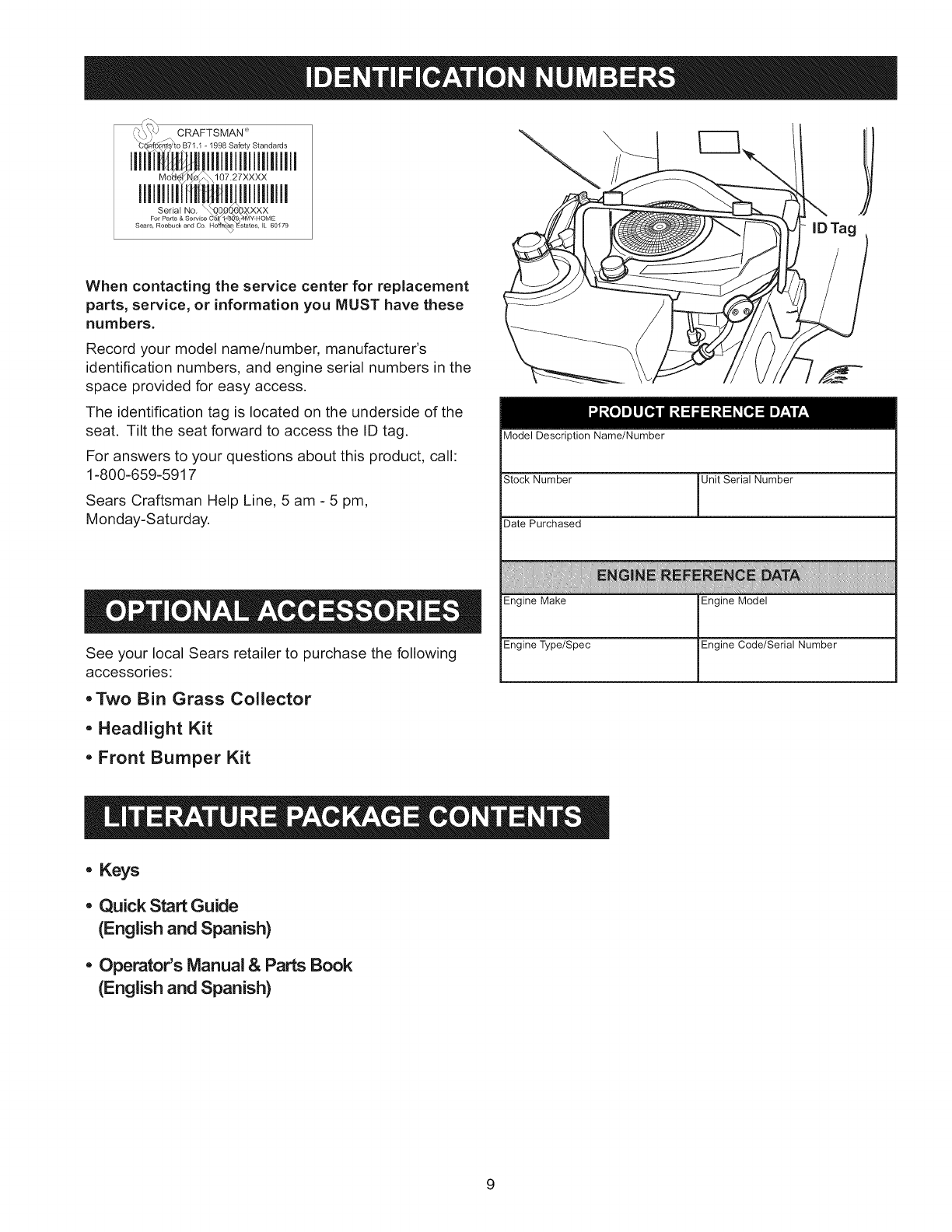
_(\_\_' CRAFTSMAN _
When contacting the service center for replacement
parts, service, or information you MUST have these
numbers.
Record your model name/number, manufacturer's
identification numbers, and engine serial numbers in the
space provided for easy access.
The identification tag is located on the underside of the
seat. Tilt the seat forward to access the ID tag.
For answers to your questions about this product, call:
1-800=659=5917
Sears Craftsman Help Line, 5 am -5 pm,
Monday=Saturday.
See your local Sears retailer to purchase the following
accessories:
Model Description Name/Number
Stock Number Unit Serial Number
Date Purchased
Engine Make Engine Model
Engine Type/Spec Engine Code/Serial Number
, Two Bin Grass Collector
,Headlight Kit
, Front Bumper Kit
,Keys
,Quick Start Guide
(English and Spanish)
,Operator's Manual & Parts Book
(English and Spanish)
9

INSTALLING THE SEAT
1. Raise the seat base (see Figure 1).
2. Align the holes in the seat bottom with the holes in
the seat base.
3. Secure the seat to the seat base with two 5/16-18 x
3/4 serrated head bolts for the rear seat slots, and
two 5/16-18 x 3/4 shoulder bolts for the front slots.
4. Tighten to 14-19 ft-lbs (19-25 Nm).
/
J
5/16-18 x 3/4
19-25 Nm
14-19 ft-lbs
5/16-18 x 3/4
Figure 1. Installing the Seat
10
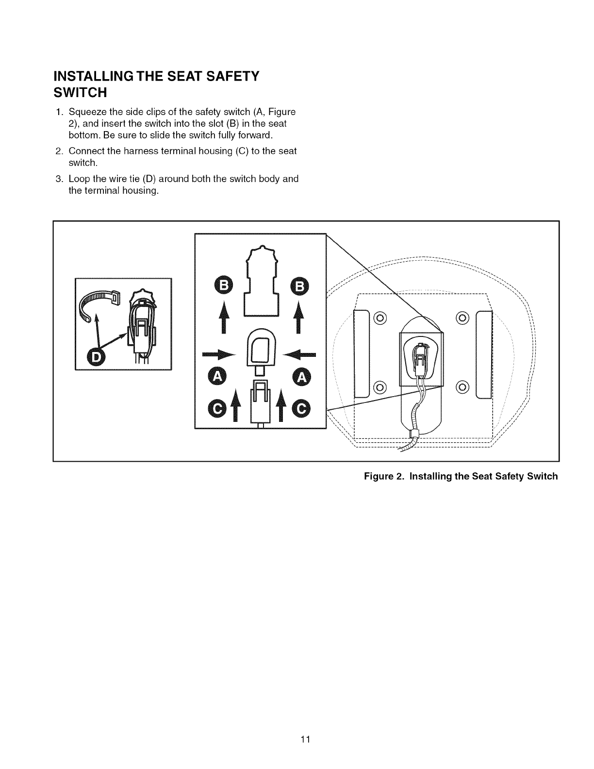
INSTALLING THE SEAT SAFETY
SWITCH
1. Squeeze the side clips of the safety switch (A, Figure
2), and insert the switch into the slot (B) in the seat
bottom. Be sure to slide the switch fully forward.
2. Connect the harness terminal housing (C) to the seat
switch.
,Loop the wire tie (D) around both the switch body and
the terminal housing.
t
t
t
Figure 2. Installing the Seat Safety Switch
11
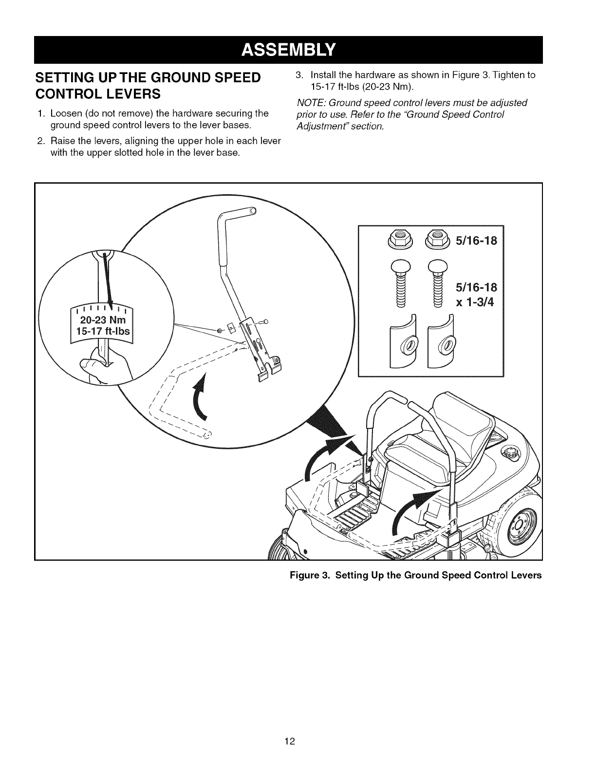
SETTING UP THE GROUND SPEED
CONTROL LEVERS
1. Loosen (do not remove) the hardware securing the
ground speed control levers to the lever bases.
2. Raise the levers, aligning the upper hole in each lever
with the upper slotted hole in the lever base.
3. Install the hardware as shown in Figure 3. Tighten to
15-17 ft-lbs (20-23 Nm).
NOTE: Ground speed control levers must be adjusted
prior to use. Refer to the "Ground Speed Control
Adjustment" section.
20-23 Nm
15-17 ftqbs
_ 5/16-18
(_ (_ 5/16-18
x 1-3/4
Figure 3. Setting Up the Ground Speed Control Levers
12
Remove the Packaging Materials
........... i
Remove the cardboard from the crate.
Remove any steel branding securing the
unit to the crate. Locate the manual
packet.
Read the Operator's Manual
Locate the operator's manual in the
manual packet. You should always read and follow the
instructions in the operator's manual. Proper care,
performance tips, and safety information are located in
this important document.
Check the Tire Pressure
Reduce the tire pressures to the
pressures shown below. Tires are over-
inflated for shipping purposes and must
be set to the correct pressures for
optimum traction.
RearTire Pressure: 10-12 PSI
Front Tire Pressure: 18=20 PSi
Check Engine Oil Level
FUI
Note: Engine is shipped with off. Add
10W-30 premium engine off if off level is
low. See MAINTENANCE for complete
engine oil specifications and maintenance
requirements.
Lift the seat deck (Figure 15) to access
the engine compartment.
Clean the area around the dip stick/oil fill
tube. Remove the dip stick from the oil fill
tube and wipe the dip stick with a clean rag.
Insert the dip stick into the oil fill tube (thread in or push
down completely).
Remove and check the engine oil level. Oil level should
be between Full and Add marks. If necessary, add oil to
the oil fill tube.
Replace and fully secure the dip stick.
Fill=Up with FRESH Gasoline
Lift the seat deck to access the
fuel cap and tank.
Remove the fuel tank cap and fill
the tank with fresh fuel. After
\, ,.,,_,',_//_ fueling, securely install the cap
and wipe up any fuel that may
have spilled. See the Operator's Manual for fuel
recommendations.
The single most common service issue is stale or
contaminated fuel! Fuel should not be more than 30
days old. Use fuel stabilizer to extend the life of your
fuel, and always store fuel in an approved, sealed, plastic
gas can. Stale fuel clean=out is not covered under your
warranty.
Fuel Tank Capacity: 4.0 Gallons (15,14 L)
Start the Engine and Drive the Unit Off the
Crate
Refer to the STARTING THE ENGINE and DRIVING
PRACTICE sections of this manual for information on
starting the unit and driving it off the crate.
Charge the Battery
Lift the seat deck to access the battery.
If the unit is being put into service after
the month and year indicated on the
battery date tag (located on top of
battery) charge the battery for one hour
at 6=10 amps. Refer to the SERVICE &
ADJUSTMENTS section of this manual for battery
charging information.
13
ParkinBrakeLever- .,=..._-
ENGAGEPositon _F
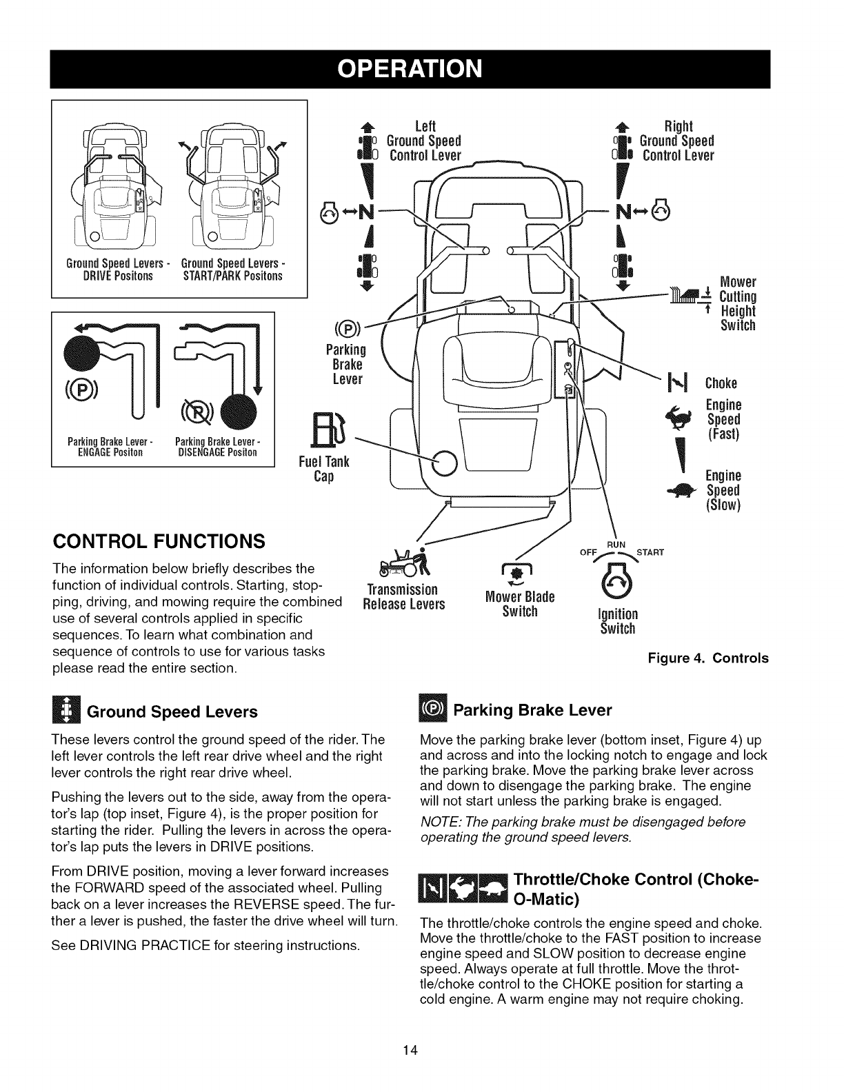
CONTROL FUNCTIONS
The information below briefly describes the
function of individual controls. Starting, stop- Transmission MowerBlade
ping, driving, and mowing require the combined ReleaseLevers Switch
use of several controls applied in specific
sequences. To learn what combination and
sequence of controls to use for various tasks
please read the entire section.
Right
GroundSpeed
ControlLever
L
ignition
Switch
Figure 4. Controls
Ground Speed Levers
These levers control the ground speed of the rider. The
left lever controls the left rear drive wheel and the right
lever controls the right rear drive wheel.
Pushing the levers out to the side, away from the opera-
tor's lap (top inset, Figure 4), is the proper position for
starting the rider. Pulling the levers in across the opera-
tot's lap puts the levers in DRIVE positions.
From DRIVE position, moving a lever forward increases
the FORWARD speed of the associated wheel. Pulling
back on a lever increases the REVERSE speed. The fur-
ther a lever is pushed, the faster the drive wheel will turn.
See DRIVING PRACTICE for steering instructions.
Parking Brake Lever
Move the parking brake lever (bottom inset, Figure 4) up
and across and into the locking notch to engage and lock
the parking brake. Move the parking brake lever across
and down to disengage the parking brake. The engine
will not start unless the parking brake is engaged.
NOTE: The parking brake must be disengaged before
operating the ground speed levers.
_r3_ Throttle/Choke Control (Choke-
O-Matic)
The throttle/choke controls the engine speed and choke.
Move the throttle/choke to the FAST position to increase
engine speed and SLOW position to decrease engine
speed. Always operate at full throttle. Move the throt-
tle/choke control to the CHOKE position for starting a
cold engine. A warm engine may not require choking.
14
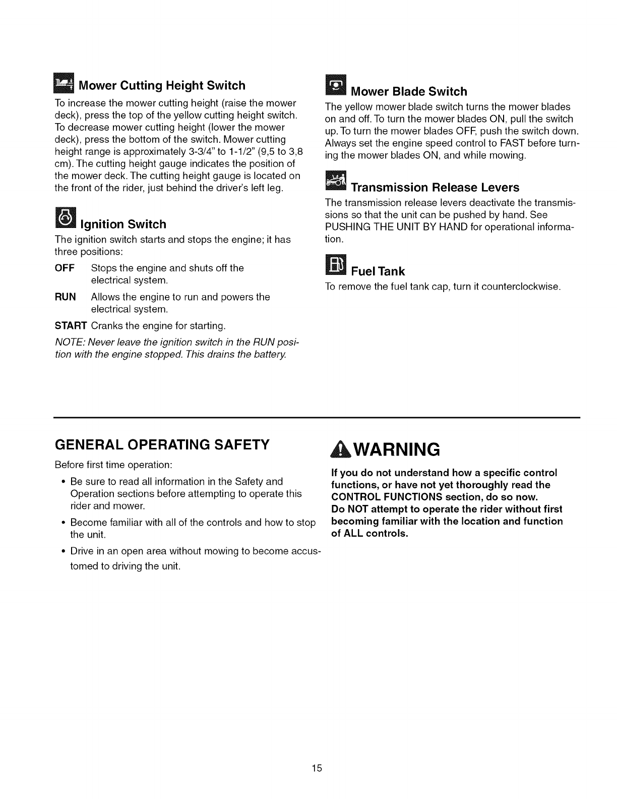
Mower Cutting Height Switch
To increase the mower cutting height (raise the mower
deck), press the top of the yellow cutting height switch.
To decrease mower cutting height (lower the mower
deck), press the bottom of the switch. Mower cutting
height range is approximately 3-3/4" to 1-1/2" (9,5 to 3,8
cm). The cutting height gauge indicates the position of
the mower deck. The cutting height gauge is located on
the front of the rider, just behind the driver's left leg.
Ignition Switch
The ignition switch starts and stops the engine; it has
three positions:
OFF Stops the engine and shuts off the
electrical system.
RUN Allows the engine to run and powers the
electrical system.
START Cranks the engine for starting.
NOTE: Never leave the ignition switch in the RUN posi-
tion with the engine stopped. This drains the battery.
_Mower Blade Switch
The yellow mower blade switch turns the mower blades
on and off. To turn the mower blades ON, pull the switch
up. To turn the mower blades OFF, push the switch down.
Always set the engine speed control to FAST before turn-
ing the mower blades ON, and while mowing.
Transmission Release Levers
The transmission release levers deactivate the transmis-
sions so that the unit can be pushed by hand. See
PUSHING THE UNIT BY HAND for operational informa-
tion.
Fuel Tank
To remove the fuel tank cap, turn it counterclockwise.
GENERAL OPERATING SAFETY
Before first time operation:
• Be sure to read all information in the Safety and
Operation sections before attempting to operate this
rider and mower.
• Become familiar with all of the controls and how to stop
the unit.
• Drive in an open area without mowing to become accus-
tomed to driving the unit.
AWARNING
If you do not understand how a specific control
functions, or have not yet thoroughly read the
CONTROL FUNCTIONS section, do so now.
Do NOT attempt to operate the rider without first
becoming familiar with the location and function
of ALL controls.
15
CHECKS BEFORE STARTING
•Check that the crankcase oil is filled to full mark on
dipstick.
• Fill the fuel tank with fresh fuel.
FUEL RECOMMENDATIONS
For daily operation: Use only unleaded gasoline with a
pump sticker octane rating of 87 or higher. Gasohol (up
to 10% ethyl alcohol, 90% unleaded gasoline by volume)
is approved as a fuel. Methyl Teriary Butyl Ether (MTBE)
and unleaded gasoline blends (up to a maximum of 15%
MTBE by volume) are approved as a fuel. No other gaso-
line/alcohol or gasoline/ether blends are approved. Do
not use fuel additives other than fuel stabilizer.
For storage: CAUTION: Alcohol blended fuels (called
gasohol or using ethanol or methanol) can attract mois-
ture which leads to separation and formation of acids
during storage. Acidic gas can damage the fuel system
of an engine while in storage.
To avoid engine problems always use fuel stabilizer,
especially before storage of 30 days or longer. Use fresh
fuel next season. See STORAGE instructions for addi-
tional information.
Never use engine or carburetor cleaner products in the
fuel tank or permanent damage may occur. To add fuel:
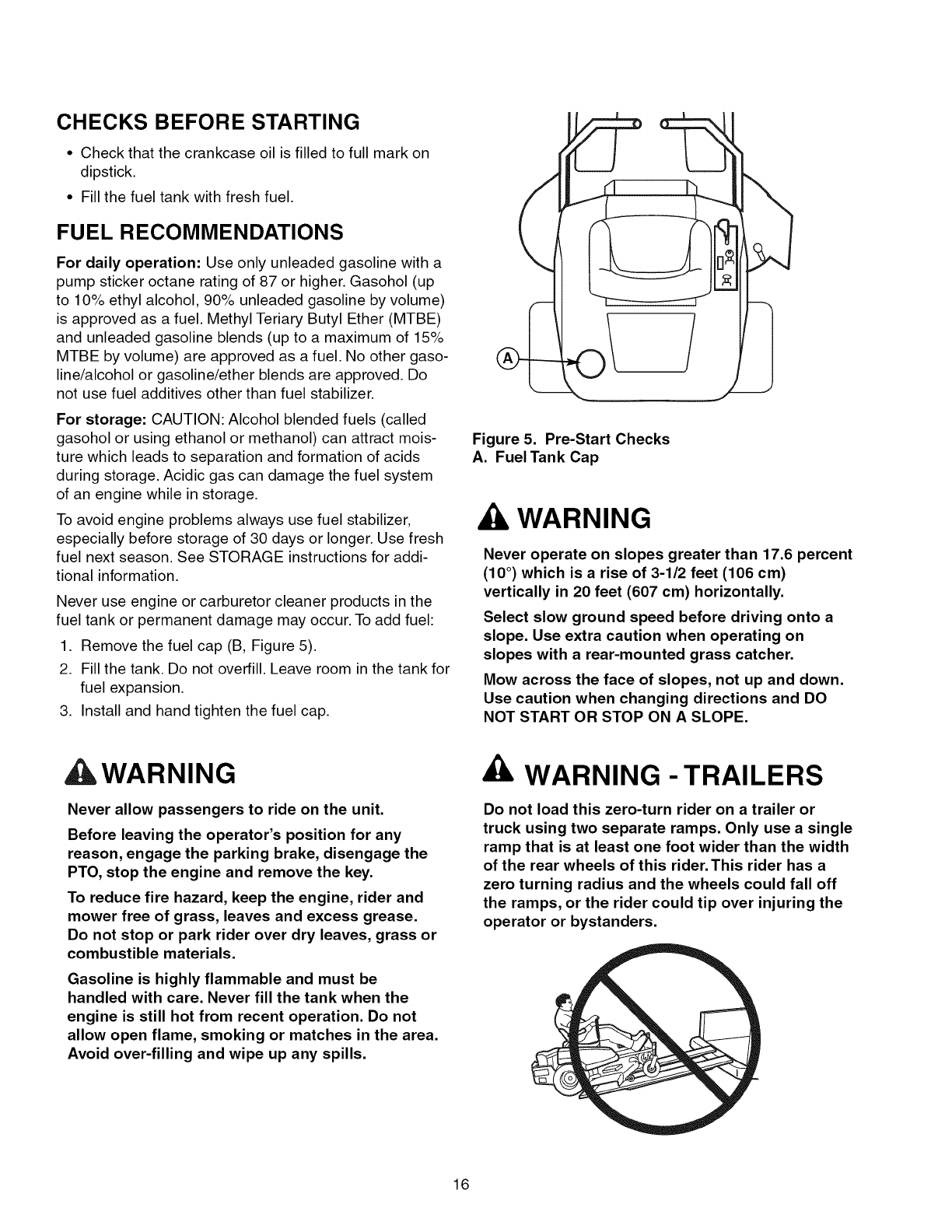
1. Remove the fuel cap (B, Figure 5).
2. Fill the tank. Do not overfill. Leave room in the tank for
fuel expansion.
3. Install and hand tighten the fuel cap.
Figure 5. Pre-Start Checks
A. Fuel Tank Cap
WARNING
Never operate on slopes greater than 17.6 percent
(10 °) which is a rise of 3-1/2 feet (106 cm)
vertically in 20 feet (607 cm) horizontally.
Select slow ground speed before driving onto a
slope. Use extra caution when operating on
slopes with a rear-mounted grass catcher.
Mow across the face of slopes, not up and down.
Use caution when changing directions and DO
NOT START OR STOP ON A SLOPE.
AWARNING
Never allow passengers to ride on the unit.
Before leaving the operator's position for any
reason, engage the parking brake, disengage the
PTO, stop the engine and remove the key.
To reduce fire hazard, keep the engine, rider and
mower free of grass, leaves and excess grease.
Do not stop or park rider over dry leaves, grass or
combustible materials.
Gasoline is highly flammable and must be
handled with care. Never fill the tank when the
engine is still hot from recent operation. Do not
allow open flame, smoking or matches in the area.
Avoid over-filling and wipe up any spills.
WARNING - TRAILERS
Do not load this zero-turn rider on a trailer or
truck using two separate ramps. Only use a single
ramp that is at least one foot wider than the width
of the rear wheels of this rider. This rider has a
zero turning radius and the wheels could fall off
the ramps, or the rider could tip over injuring the
operator or bystanders.
16
EMERGENCY STOPPING
In the event of an emergency the engine can be stopped
by simply turning the ignition switch to STOP. Use this
method only in emergency situations. For normal engine
shut down follow the procedure given in STOPPING THE
RIDER AND ENGINE.
STOPPING THE RIDER &ENGINE
1. Return the ground speed control levers to
START/PARK positions to stop rider movement.
2. Engage the parking brake.
3. Turn off the mower blades by pushing the mower
blade switch down to the OFF position.
4. Move the engine speed control to SLOW position and
turn the ignition switch to OFE Remove the key.
STARTING THE ENGINE
1. While sitting in the seat, make sure the mower blade
switch is OFF, the ground speed control levers are
locked in START/PARK positions, and the parking
brake is engaged.
2. Move the throttle/choke control to the CHOKE posi-
tion for starting a cold engine. A warm engine may
not require choking.
3. Insert the key into the ignition switch and turn it to
START to crank the engine.
4. After the engine starts, release the key. It will return to
the RUN position.
5. Move the throttle/choke to the FAST position to
increase engine speed and SLOW position to
decrease engine speed. Always operate at full throt-
tle.
6. Warm the engine by running it for at least a minute
before turning on the mower blades, or driving the
unit.
ALWAYS operate the unit with the throttle/choke
control set to FAST when mowing or driving,
NEVER engage the mower blades with the engine
speed set to SLOW,
MOWING
1. Start the engine (see STARTING THE ENGINE).
2. Set the mower cutting height to the desired setting
using the mower cutting height switch.
3. Set the engine speed control to FAST.
4. Turn the mower blades ON (pull switch up).
5. Disengage the parking brake.
6. Move the ground speed control levers in from
START/PARK positions to drive positions (levers in
across the operator's lap).
7. Begin mowing. See DRIVING PRACTICE.
8. When finished, turn the mower blades OFF (push
switch down).
9. Stop the rider and engine (see STOPPING THE
RIDER AND ENGINE).
PUSHING THE RIDER BY HAND
NOTE: Do not disengage the transmission if parked on a
slope
,Turn the mower blades OFF, push the ground speed
control levers out to their START/PARK positions,
engage the parking brake, turn the ignition switch
OFF, remove the key, and wait for all moving parts to
stop.
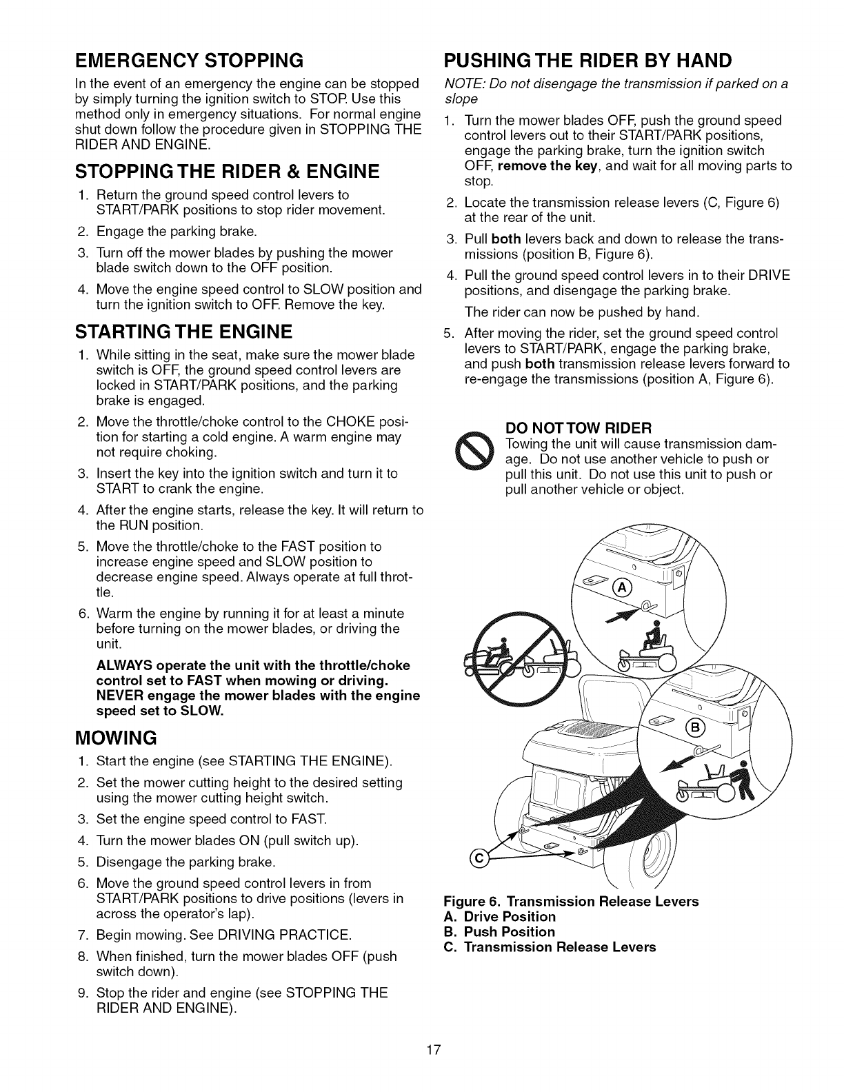
2. Locate the transmission release levers (C, Figure 6)
at the rear of the unit.
,
4.
,
Pull both levers back and down to release the trans-
missions (position B, Figure 6).
Pull the ground speed control levers in to their DRIVE
positions, and disengage the parking brake.
The rider can now be pushed by hand.
After moving the rider, set the ground speed control
levers to START/PARK, engage the parking brake,
and push both transmission release levers forward to
re-engage the transmissions (position A, Figure 6).
®DO NOTTOW RIDER
Towing the unit will cause transmission dam-
age. Do not use another vehicle to push or
pull this unit. Do not use this unit to push or
pull another vehicle or object.
Figure 6, Transmission Release Levers
A, Drive Position
B. Push Position
C. Transmission Release Levers
17

DRIVING PRACTICE -
BASIC DRIVING
WARNING: Never operate on slopes greater than 17.6%
(10°). See SLOPE OPERATION in the safety section.
Zero turn riders operate differently from other four-
wheeled vehicles. The drive wheels are also your steer-
ing wheels. If you cannot drive the unit on a hill, you will
not be able to steer the unit on it. Operating zero turn
units on slopes requires extra caution.
The lever controls of the zero turn rider are very respon-
sive, and learning to gain a smooth and efficient control
of the rider's forward, reverse, and turning movements
will take some practice.
Spend some time going through the following maneuvers
and becoming familiar with how the unit accelerates,
travels, and steers - before you begin mowing - is
absolutely essential to getting the most out of the zero
turn rider.
Locate a smooth, flat area of your lawn - one with
plenty of room to maneuver. (Clear the area of objects,
people and animals before you begin.) Operate the unit
at mid-throttle during this practice session (ALWAYS
operate at full throttle when mowing), and turn slowly to
prevent tire slippage and damage to your lawn.
We suggest you begin with the Smooth Travel procedure
to the right, and then advance through the forward,
reverse, and turning maneuvers.
WARNING
Do not mow in reverse unless absolutely
necessary. Always look down and behind before
and while travelling in reverse.
Forward Travel
Smooth Travel
The lever controls of the
zero turn rider are
highly responsive.
The BEST method of
handling the ground
speed control levers is in
three steps - as shown
in Figure 7.
FIRST place your hands
onto the levers as
shown.
SECOND, to go forward
gradually push the levers
forward with your palms.
THIRD, to speed up
move the levers farther
forward. To slow down
smoothly, slowly move
the levers back toward
neutral.
Figure 7. Move Control
Levers Gradually
Forward Travel Practice
Gradually move both ground speed control levers evenly
FORWARD from neutral (see Figure 8). Slow down and
repeat.
Reverse Travel Practice
LOOK DOWN & BEHIND, then gradually move both
ground speed control levers evenly BACK from neutral
(see Figure 9). Slow down and repeat.
NOTE: Practice backing up for several minutes before
attempting to do so near objects. The rider turns as
sharply in reverse as when going forward, and backing
up straight takes practice.
Reverse Travel
Figure 8. Forward Travel Figure 9. Reverse Travel
18
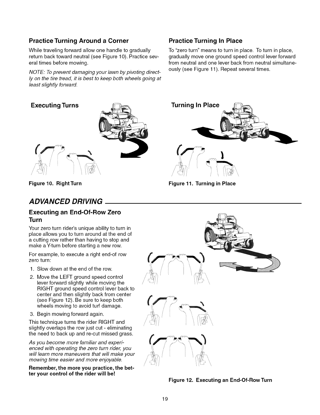
Practice Turning Around a Corner
While traveling forward allow one handle to gradually
return back toward neutral (see Figure 10). Practice sev-
eral times before mowing.
NOTE: To prevent damaging your lawn by pivoting direct-
ly on the tire tread, it is best to keep both wheels going at
least slightly forward.
Practice Turning In Place
To "zero turn" means to turn in place. To turn in place,
gradually move one ground speed control lever forward
from neutral and one lever back from neutral simultane-
ously (see Figure 11). Repeat several times.
Executing Turns
Figure 10. RightTurn
Turning In Place
/
Figure 11. Turning in Place
ADVANCED DRIVING
Executing an End-Of-Row Zero
Turn
Your zero turn rider's unique ability to turn in
place allows you to turn around at the end of
a cutting row rather than having to stop and
make a Y-turn before starting a new row.
For example, to execute a right end-of row
zero turn:
,
2.
Slow down at the end of the row.
Move the LEFT ground speed control
lever forward slightly while moving the
RIGHT ground speed control lever back to
center and then slightly back from center
(see Figure 12). Be sure to keep both
wheels moving to avoid turf damage.
3. Begin mowing forward again.
This technique turns the rider RIGHT and
slightly overlaps the row just cut - eliminating
the need to back up and re-cut missed grass.
As you become more familiar and experi-
enced with operating the zero turn rider, you
will learn more maneuvers that will make your
mowing time easier and more enjoyable.
Remember, the more you practice, the bet-
ter your control of the rider will be!
Figure 12. Executing an End-Of-Row Turn
19
MOWER DECK REMOVAL &
INSTALLATION
NOTE: Perform mower removal and installation on a
hard, level surface such as a concrete floor.
WARNING
After lowering the mower cutting height, engage
parking brake, turn off the mower blades, turn the
ignition switch to STOP, and remove key before
attempting to install or remove the mower.
Removing the Mower Deck
1. Turn the mower blades OFF, put the ground speed
control levers in START/PARK position, engage the
parking brake, turn the ignition OFF, and wait for all
moving parts to stop.
2. Pivot the front wheels forward.
3. Use the mower belt release lever (D, Figure 13) to
release belt tension. Remove the mower belt (B) from
engine pulley (A).
4. Turn the ignition switch from OFF to RUN without
starting the engine.
5. Use the mower cutting height switch to raise the
mower deck.
6. Place 4x4 wood blocks under the front and rear lip of
the mower deck to securely support it.
7. Use the mower cutting height switch to fully lower the
mower so that is it resting on the 4x4 wood blocks (A,
Figure 14).
8. Turn the ignition switch to OFF and remove the key.
9. Remove the hair pin clip (B) securing the rear mower
lift arm. Separate the lift arm from the mower deck.
Repeat on both sides of the mower.
10. Remove the 3/8 -16 x 3/4 carriage bolts and flange
nuts (C) that secure the front hitch rod, then remove
the hitch rod (D).
11. Slide the mower deck out from under the rider.
Installing
1. Slide the
the Mower Deck
mower deck under the right side of the rider.
Slide the mower forward and hook the front hitch rod
(D, Figure 14) to the front mower deck hooks.
2. Secure front hitch rod with two 3/8 -16 x 3/4 carriage
bolts and flange nuts (C).
3. Slide the mower deck backwards and connect the
rear lift arms to the mower deck. Secure with hair pin
clips (B).
4. Insert the key into the ignition switch. Turn the switch
from OFF to RUN without starting the engine.
5. Use the cutting height switch to raise the mower until
it is no longer resting on the 4x4 wood blocks (A).
6. Turn the ignition switch OFF and remove the key.
Remove the 4x4 blocks.
7. Use the mower belt release lever (D, Figure 13) to
release mower belt tension, and install the belt as
shown.
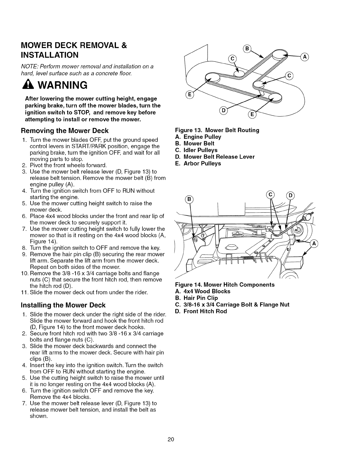
Figure 13. Mower Belt Routing
A. Engine Pulley
B. Mower Belt
C. Idler Pulleys
D. Mower Belt Release Lever
E. Arbor Pulleys
Figure 14. Mower Hitch Components
A. 4x4 Wood Blocks
B. Hair Pin Clip
C. 3/8-16 x 314 Carriage Bolt & Flange Nut
D. Front Hitch Rod
20

MAINTENANCE SCHEDULE
The following schedules should be followed for normal care of your rider and mower.
RIDER MAINTENANCE, All Models Before Spring 8 25 100 200 Yearly
Each Use & Fall Hours Hours Hours Hours
Clean Debris from Rider and Engine Compartment * •
Clean Debris from Engine Cooling Areas & Air Filter * •
Check Tire Pressure •
Lubricate Rider & Mower * •
Clean Deck & Check/Replace Mower Blades •
Clean Battery & Cables •
Check Rider Safety System ** • • •
Check /Adjust PTO Clutch •
ENGINE MAINTENANCE, 8 Hours or 25 Hours or 50 Hours or 100 Hours or Yearly
21HP Briggs & Stratton Daily Every Every Every
Season Season Season
Check Engine Oil Level * •
Service Air Pre-Cleaner * •
Change Oil * •
Service Air Filter * •
Change Oil & Filter * •
Clean Cooling Fins * •
Replace Air Filter * •
Replace Spark Plug •
Replace Fuel Filter 1 •
Check Valve Clearance 1" •
* More often in hot (over 85° F: 30° C) weather or dusty operating conditions.
** Check the function of the safety system after the unit has been stored for 30 days or longer.
1"These services should be performed by Sears or other qualified service dealer.
21
Rider Maintenance Items
WARNING
Move the ground speed levers to START/PARK
positions, engage the parking brake, turn the
mower blades OFF, turn the ignition switch OFF,
and wait for all moving parts to stop before
accessing the engine compartment or
performing any maintenance procedures.
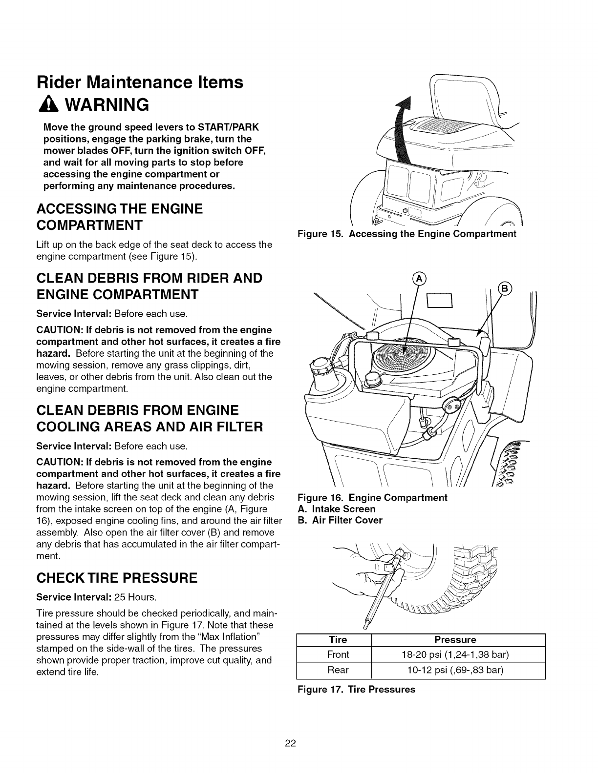
ACCESSING THE ENGINE
COMPARTMENT
Lift up on the back edge of the seat deck to access the
engine compartment (see Figure 15).
CLEAN DEBRIS FROM RIDER AND
ENGINE COMPARTMENT
Service Interval: Before each use.
CAUTION: If debris is not removed from the engine
compartment and other hot surfaces, it creates a fire
hazard. Before starting the unit at the beginning of the
mowing session, remove any grass clippings, dirt,
leaves, or other debris from the unit. Also clean out the
engine compartment.
CLEAN DEBRIS FROM ENGINE
COOLING AREAS AND AIR FILTER
Service Interval: Before each use.
CAUTION: If debris is not removed from the engine
compartment and other hot surfaces, it creates a fire
hazard. Before starting the unit at the beginning of the
mowing session, lift the seat deck and clean any debris
from the intake screen on top of the engine (A, Figure
16), exposed engine cooling fins, and around the air filter
assembly. Also open the air filter cover (B) and remove
any debris that has accumulated in the air filter compart-
ment.
CHECK TIRE PRESSURE
Service Interval: 25 Hours.
Tire pressure should be checked periodically, and main-
tained at the levels shown in Figure 17. Note that these
pressures may differ slightly from the "Max Inflation"
stamped on the side-wall of the tires. The pressures
shown provide proper traction, improve cut quality, and
extend tire life.
Figure 15. Accessing the Engine Compartment
Figure 16. Engine Compartment
A. Intake Screen
B. Air Filter Cover
Tire Pressure
Front 18-20 psi (1,24-1,38 bar)
Rear 10-12 psi (,69-,83 bar)
Figure 17. Tire Pressures
22
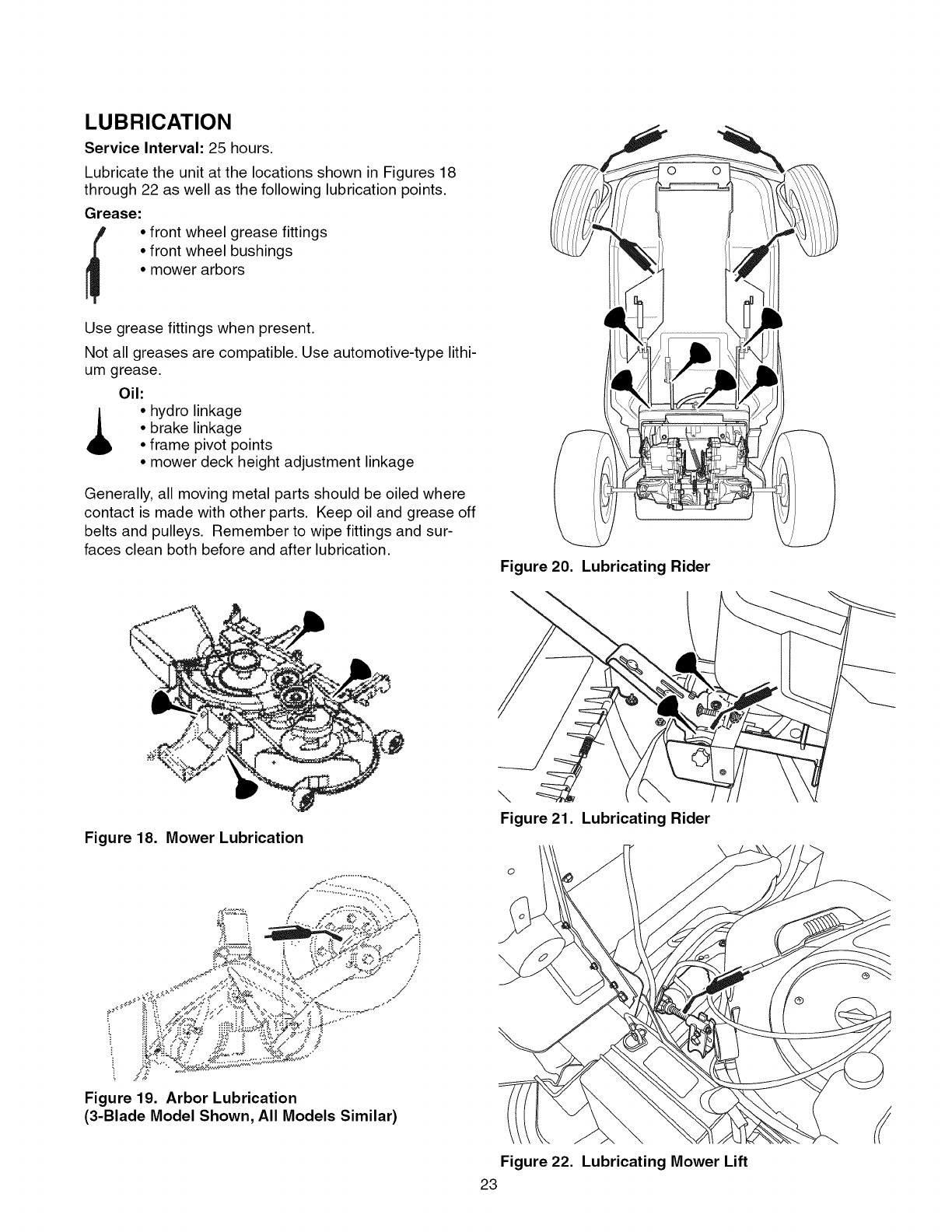
LUBRICATION
Service Interval: 25 hours.
Lubricate the unit at the locations shown in Figures 18
through 22 as well as the following lubrication points.
Grease:
• front wheel grease fittings
• front wheel bushings
• mower arbors
Use grease fittings when present.
Not all greases are compatible. Use automotive-type lithi-
um grease.
Oil:
• hydro linkage
• brake linkage
• frame pivot points
• mower deck height adjustment linkage
Generally, all moving metal parts should be oiled where
contact is made with other parts. Keep oil and grease off
belts and pulleys. Remember to wipe fittings and sur-
faces clean both before and after lubrication.
Figure 18. Mower Lubrication
t 4
_. x,_/" _
ii7; ";'_'_'<'_....
Figure 19. Arbor Lubrication
(3-Blade Model Shown, All Models Similar)
Figure 20. Lubricating Rider
\
\
Figure 21. Lubricating Rider
o
Figure 22. Lubricating Mower Lift
23
CLEAN DECK &
CHECK/REPLACE MOWER BLADES
Service Interval: 25 hours or as required.
WARNING
For your personal safety, do not handle the sharp
mower blades with bare hands. Careless or
improper handling of blades may result in serious
injury.
WARNING
For your personal safety, blade mounting
capscrews must each be installed with two spring
washers or a hex washer and spring washer, then
securely tightened. Torque blade mounting nut to
80-90 ft-lbs (108-122 Nm).
1. Remove mower deck (see "Mower Deck Removal" in
the OPERATION section).
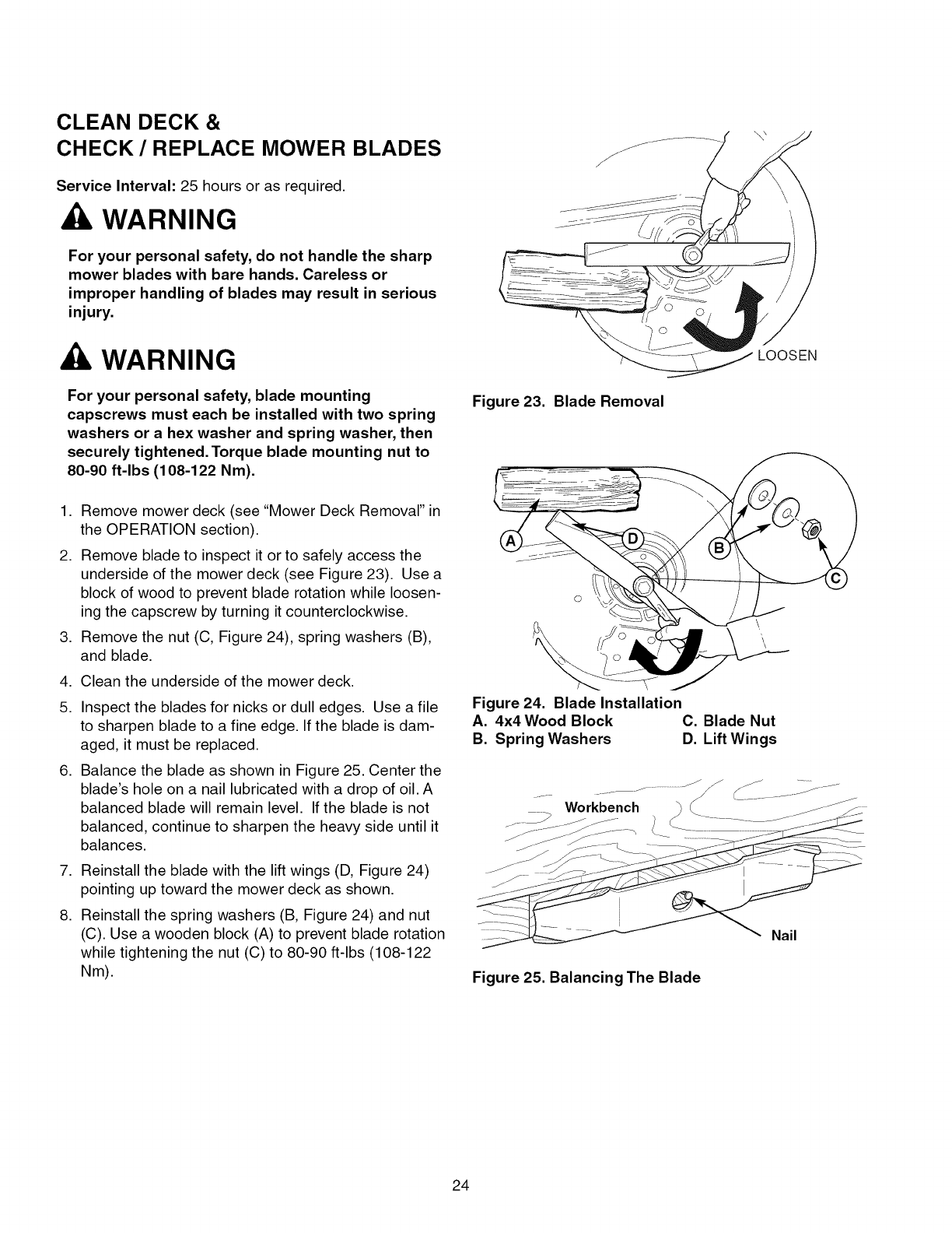
2. Remove blade to inspect it or to safely access the
underside of the mower deck (see Figure 23). Use a
block of wood to prevent blade rotation while loosen-
ing the capscrew by turning it counterclockwise.
3. Remove the nut (C, Figure 24), spring washers (B),
and blade.
.
5.
.
.
.
Clean the underside of the mower deck.
Inspect the blades for nicks or dull edges. Use a file
to sharpen blade to a fine edge. If the blade is dam-
aged, it must be replaced.
Balance the blade as shown in Figure 25. Center the
blade's hole on a nail lubricated with a drop of oil. A
balanced blade will remain level. If the blade is not
balanced, continue to sharpen the heavy side until it
balances.
Reinstall the blade with the lift wings (D, Figure 24)
pointing up toward the mower deck as shown.
Reinstall the spring washers (B, Figure 24) and nut
(C). Use a wooden block (A) to prevent blade rotation
while tightening the nut (C) to 80-90 ft-lbs (108-122
Nm).
LOOSEN
Figure 23. Blade Removal
Figure 24. Blade Installation
A. 4x4 Wood Block C. Blade Nut
B. Spring Washers D. Lift Wings
Workbench
Figure 25. Balancing The Blade
Nail
24
CLEANING THE BATTERY AND
CABLES
WARNING
Corrosion hazard.
Batteries contain acid. Always keep the
battery upright and do not spill the
electrolyte. Avoid contact with skin and
eyes.
Explosion hazard.
Changing the battery produces explosive
hydrogen gas. Only charge the battery in a
well ventilated area, away from any ignition
source such as a water heater, electric
motor, or a lit cigarette.
Wear Protective Equipment
Always wear gloves and safety glasses
when handling the battery and battery
cables.
Service Interval: 100 Hours
.
2.
3.
4.
5.
6.
.
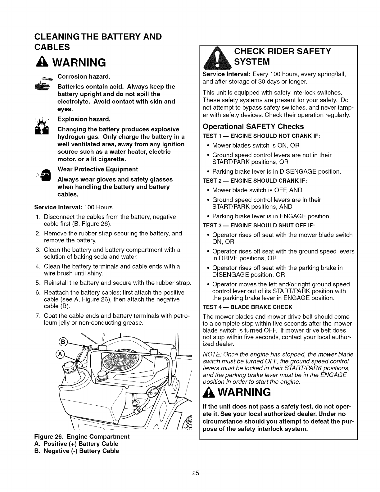
Disconnect the cables from the battery, negative
cable first (B, Figure 26).
Remove the rubber strap securing the battery, and
remove the battery.
Clean the battery and battery compartment with a
solution of baking soda and water.
Clean the battery terminals and cable ends with a
wire brush until shiny.
Reinstall the battery and secure with the rubber strap.
Reattach the battery cables: first attach the positive
cable (see A, Figure 26), then attach the negative
cable (B).
Coat the cable ends and battery terminals with petro-
leum jelly or non-conducting grease.
Figure 26. Engine Compartment
A. Positive (+) Battery Cable
B. Negative (-) Battery Cable
CHECK RIDER SAFETY
SYSTEM
Service Interval: Every 100 hours, every spring/fall,
and after storage of 30 days or longer.
This unit is equipped with safety interlock switches.
These safety systems are present for your safety. Do
not attempt to bypass safety switches, and never tamp-
er with safety devices. Check their operation regularly.
Operational SAFETY Checks
TEST 1 -- ENGINE SHOULD NOT CRANK IF:
• Mower blades switch is ON, OR
• Ground speed control levers are not in their
START/PARK positions, OR
• Parking brake lever is in DISENGAGE position.
TEST 2 -- ENGINE SHOULD CRANK IF:
• Mower blade switch is OFE AND
• Ground speed control levers are in their
START/PARK positions, AND
• Parking brake lever is in ENGAGE position.
TEST 3 -- ENGINE SHOULD SHUT OFF IF:
• Operator rises off seat with the mower blade switch
ON, OR
• Operator rises off seat with the ground speed levers
in DRIVE positions, OR
• Operator rises off seat with the parking brake in
DISENGAGE position, OR
• Operator moves the left and/or right ground speed
control lever out of its START/PARK position with
the parking brake lever in ENGAGE position.
TEST 4 -- BLADE BRAKE CHECK
The mower blades and mower drive belt should come
to a complete stop within five seconds after the mower
blade switch is turned OFE If mower drive belt does
not stop within five seconds, contact your local author-
ized dealer.
NOTE: Once the engine has stopped, the mower blade
switch must be turned OFF, the ground speed control
levers must be locked in their START/PARK positions,
and the parking brake lever must be in the ENGAGE
position in order to start the engine.
WARNING
If the unit does not pass a safety test, do not oper-
ate it. See your local authorized dealer. Under no
circumstance should you attempt to defeat the pur-
pose of the safety interlock system.
25
CHECK /ADJUST PTO CLUTCH
WARNING
To avoid serious injury, perform adjustments only
with engine stopped, key removed and tractor on
level ground.
Service Interval: 200 Hours.
The Power Take Off (PTO) clutch drives the mower
blades. The PTO clutch is engaged and disengaged by
the mower blade switch. Check the PTO clutch adjust-
ment every 200 hours of operation. Also perform the fol-
lowing procedure if the clutch is slipping, will not engage,
or if a new clutch has been installed.
1. Remove key from ignition switch and disconnect
spark plug wires to prevent the possibility of acciden-
tal starting while the PTO is being adjusted.
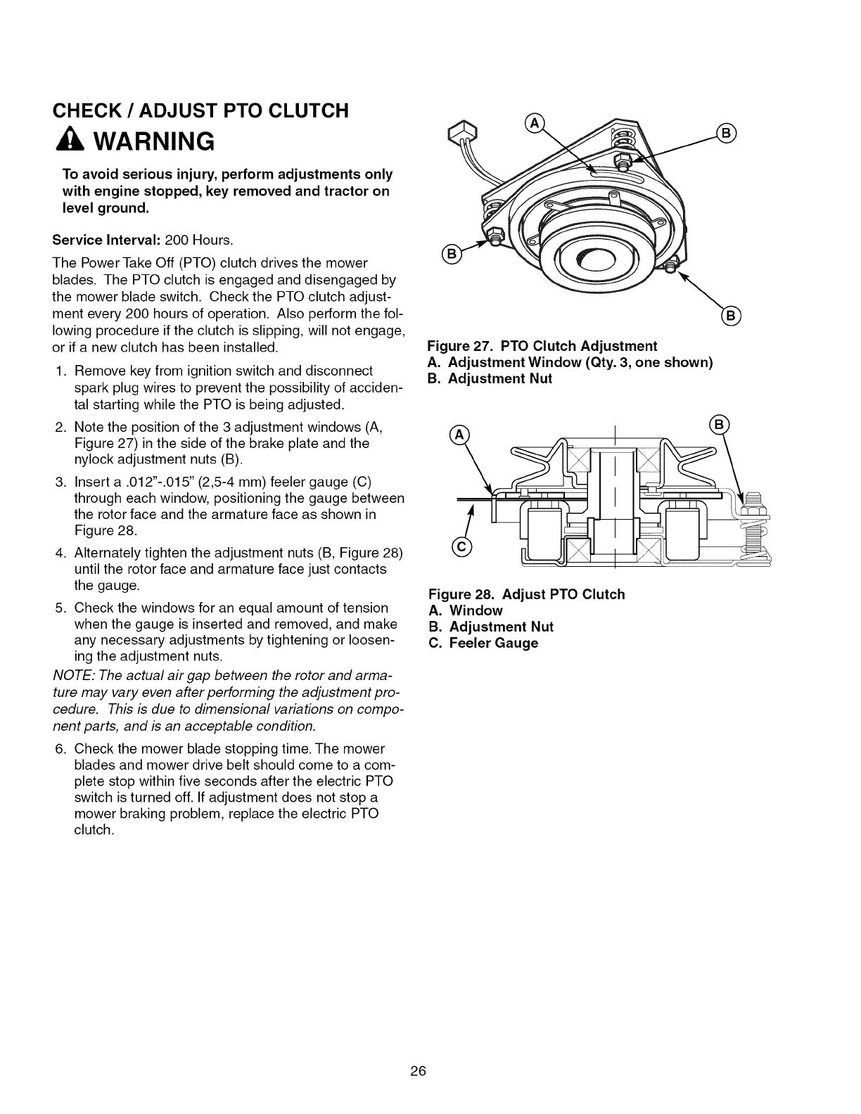
2. Note the position of the 3 adjustment windows (A,
Figure 27) in the side of the brake plate and the
nylock adjustment nuts (B).
3. Insert a .012"-.015" (2,5-4 mm) feeler gauge (C)
through each window, positioning the gauge between
the rotor face and the armature face as shown in
Figure 28.
4. Alternately tighten the adjustment nuts (B, Figure 28)
until the rotor face and armature face just contacts
the gauge.
5. Check the windows for an equal amount of tension
when the gauge is inserted and removed, and make
any necessary adjustments by tightening or loosen-
ing the adjustment nuts.
NOTE: The actual air gap between the rotor and arma-
ture may vary even after performing the adjustment pro-
cedure. This is due to dimensional variations on compo-
nent parts, and is an acceptable condition.
6. Check the mower blade stopping time. The mower
blades and mower drive belt should come to a com-
plete stop within five seconds after the electric PTO
switch is turned off. If adjustment does not stop a
mower braking problem, replace the electric PTO
clutch.
Figure 27. PTO Clutch Adjustment
A. Adjustment Window (Qty. 3, one shown)
B. Adjustment Nut
Figure 28. Adjust PTO Clutch
A. Window
B. Adjustment Nut
C. Feeler Gauge
26
Engine Maintenance Items
CHECK ENGINE OIL LEVEL
Service Interval: Before each use, and every 8 hours.
1. Turn the engine off, and set the parking brake lever to
ENGAGE.
2. Clean the area around the dip stick (C, Figure 30).
3. Remove the dip stick (C) and clean it with a paper
towel.
4. Insert the dip stick back into the engine. Thread the
cap back into the tube (D).
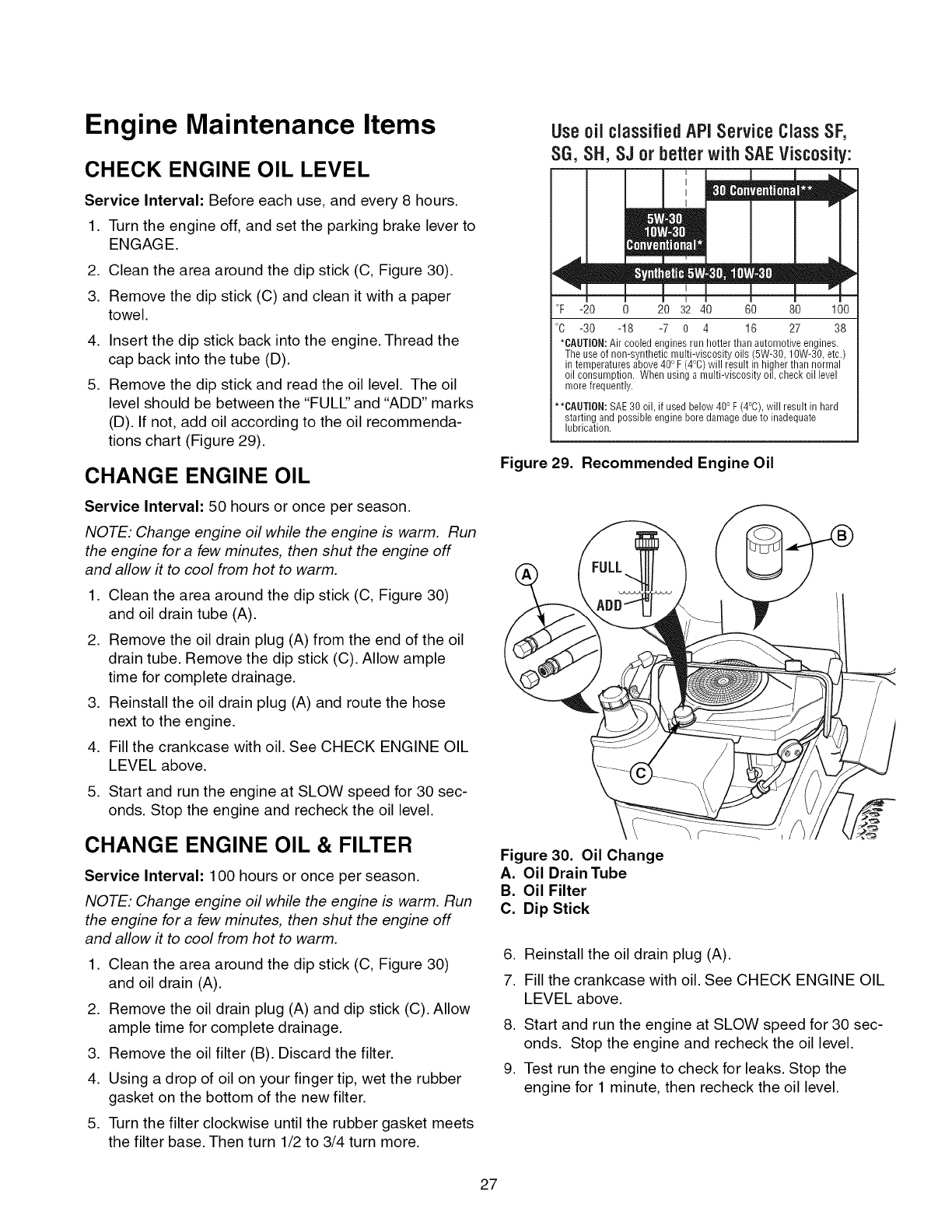
5. Remove the dip stick and read the oil level. The oil
level should be between the "FULl" and "ADD" marks
(D). If not, add oil according to the oil recommenda-
tions chart (Figure 29).
CHANGE ENGINE OIL
Service Interval: 50 hours or once per season.
NOTE: Change engine oil while the engine is warm. Run
the engine for a few minutes, then shut the engine off
and allow it to cool from hot to warm.
1. Clean the area around the dip stick (C, Figure 30)
and oil drain tube (A).
2. Remove the oil drain plug (A) from the end of the oil
drain tube. Remove the dip stick (C). Allow ample
time for complete drainage.
3. Reinstall the oil drain plug (A) and route the hose
next to the engine.
4. Fill the crankcase with oil. See CHECK ENGINE OIL
LEVEL above.
5. Start and run the engine at SLOW speed for 30 sec-
onds. Stop the engine and recheck the oil level.
CHANGE ENGINE OIL & FILTER
Service Interval: 100 hours or once per season.
NOTE: Change engine oil while the engine is warm. Run
the engine for a few minutes, then shut the engine off
and allow it to cool from hot to warm.
1. Clean the area around the dip stick (C, Figure 30)
and oil drain (A).
2. Remove the oil drain plug (A) and dip stick (C). Allow
ample time for complete drainage.
3. Remove the oil filter (B). Discard the filter.
4. Using a drop of oil on your finger tip, wet the rubber
gasket on the bottom of the new filter.
5. Turn the filter clockwise until the rubber gasket meets
the filter base. Then turn 1/2 to 3/4 turn more.
Useoil classifiedAPIService ClassSF,
SG, SH,SJ or betterwith SAEViscosity:
! I 1! I ,
°F -20 0 20 32 40 60 80 100
°O -30 -18 -7 0 4 16 27 38
*CAUTION:Air cooled engines run hotter than automotive engines.
The use of non-synthetic multi-viscosity oils (5W-30, lOW-30, etc.)
in temperatures above 400 F(4°0) will result in higher than normal
oil consumption. When using a multi-viscosity oil, check oil level
more frequently.
**CAUTION: SAE30 oil, if used below 400F (4°C), will result in hard
starting andpossible engine boredamage due to inadequate
lubrication.
Figure 29. Recommended Engine Oil
Figure 30. Oil Change
A. Oil Drain Tube
B. Oil Filter
C. Dip Stick
6. Reinstall the oil drain plug (A).
7. Fill the crankcase with oil. See CHECK ENGINE OIL
LEVEL above.
8. Start and run the engine at SLOW speed for 30 sec-
onds. Stop the engine and recheck the oil level.
9. Test run the engine to check for leaks. Stop the
engine for 1 minute, then recheck the oil level.
27
AIR FILTER & PRE-CLEANER
Service Interval: Pre-Cleaner: Every 25 hours or as
required. Air Filter: Every 50 hours or as required.
Replacement Interval: Pre-Cleaner: As required. Air
Filter: Every 200 hours or once per season.
Air Filter Removal & Installation
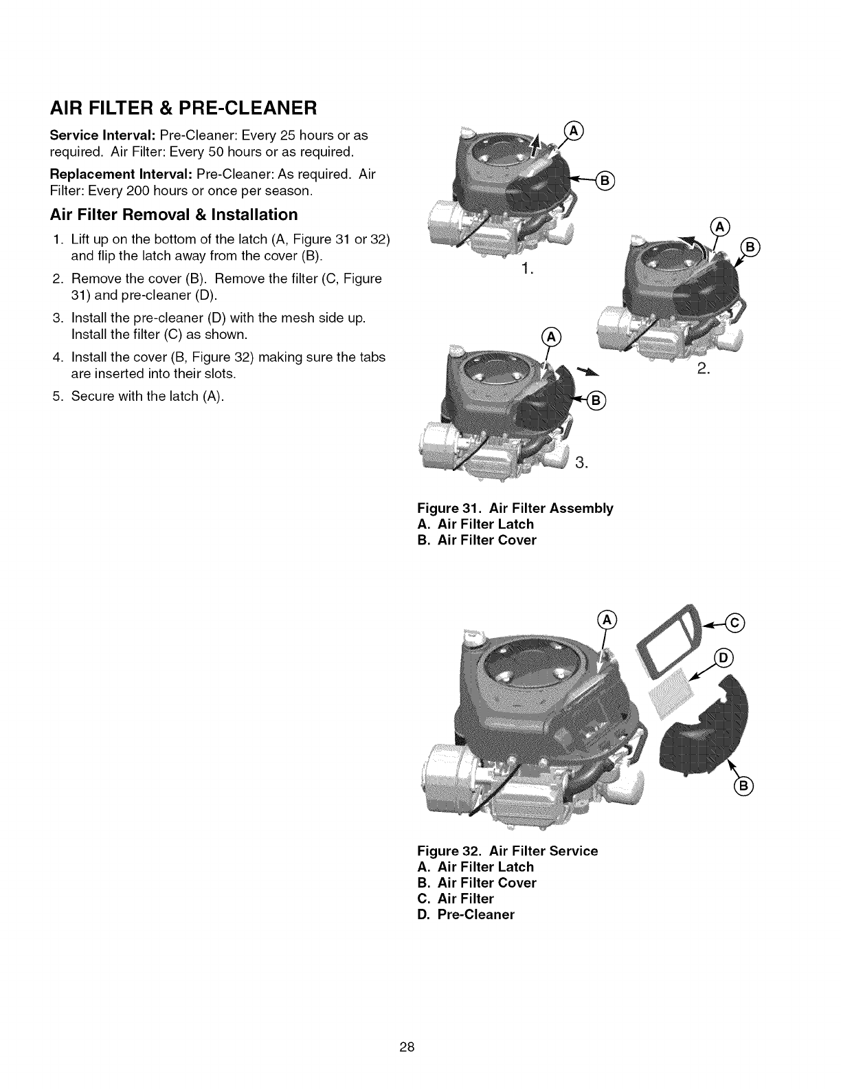
1. Lift up on the bottom of the latch (A, Figure 31 or 32)
and flip the latch away from the cover (B).
2. Remove the cover (B). Remove the filter (C, Figure
31) and pre-cleaner (D).
3. Install the pre-cleaner (D) with the mesh side up.
Install the filter (C) as shown.
4. Install the cover (B, Figure 32) making sure the tabs
are inserted into their slots.
5. Secure with the latch (A).
.
.
.
Figure 31. Air Filter Assembly
A. Air Filter Latch
B. Air Filter Cover
®
Figure 32. Air Filter Service
A. Air Filter Latch
B. Air Filter Cover
C. Air Filter
D. Pre-Cleaner
28
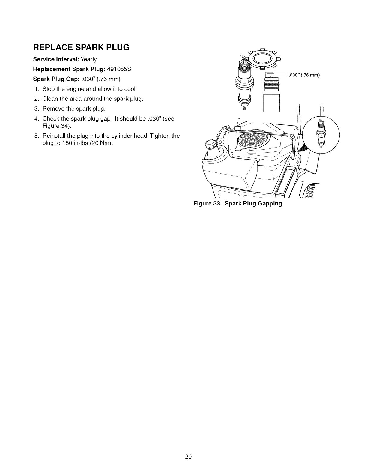
REPLACE SPARK PLUG
Service Interval: Yearly
Replacement Spark Plug: 491055S
Spark Plug Gap: .030" (.76 mm)
1. Stop the engine and allow it to cool.
2. Clean the area around the spark plug.
3. Remove the spark plug.
4. Check the spark plug gap. It should be .030" (see
Figure 34).
5. Reinstall the plug into the cylinder head. Tighten the
plug to 180 in-lbs (20 Nm).
.030" (.76 ram)
Figure 33. Spark Plug Gapping
29
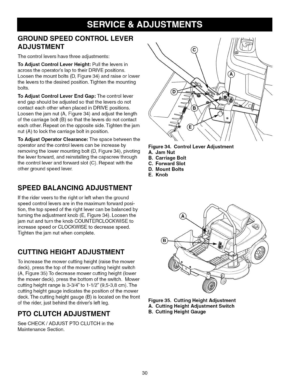
GROUND SPEED CONTROL LEVER
ADJUSTMENT
The control levers have three adjustments:
To Adjust Control Lever Height: Pull the levers in
across the operator's lap to their DRIVE positions.
Loosen the mount bolts (D, Figure 34) and raise or lower
the levers to the desired position. Tighten the mounting
bolts.
To Adjust Control Lever End Gap: The control lever
end gap should be adjusted so that the levers do not
contact each other when placed in DRIVE positions.
Loosen the jam nut (A, Figure 34) and adjust the length
of the carriage bolt (B) so that the levers do not contact
each other. Repeat on the opposite side. Tighten the jam
nut (A) to lock the carriage bolt in position.
To Adjust Operator Clearance: The space between the
operator and the control levers can be increase by
removing the lower mounting bolt (D, Figure 34), pivoting
the lever forward, and reinstalling the capscrew through
the control lever and forward slot (C). Repeat with the
other ground speed lever.
SPEED BALANCING ADJUSTMENT
If the rider veers to the right or left when the ground
speed control levers are in the maximum forward posi-
tion, the top speed of the right lever can be balanced by
turning the adjustment knob (E, Figure 34). Loosen the
jam nut and turn the knob COUNTERCLOCKWISE to
increase speed or CLOCKWISE to decrease speed.
Tighten the jam nut when complete.
\
Figure 34. Control Lever Adjustment
A. Jam Nut
B. Carriage Bolt
C. Forward Slot
D. Mount Bolts
E. Knob
CUTTING HEIGHT ADJUSTMENT
To increase the mower cutting height (raise the mower
deck), press the top of the mower cutting height switch
(A, Figure 35) To decrease mower cutting height (lower
the mower deck), press the bottom of the switch. Mower
cutting height range is 3-3/4" to 1-1/2" (9,5-3,8 cm). The
cutting height gauge indicates the position of the mower
deck. The cutting height gauge (B) is located on the front
of the rider, just behind the driver's left leg.
PTO CLUTCH ADJUSTMENT
See CHECK /ADJUST PTO CLUTCH in the
Maintenance Section.
Figure 35. Cutting Height Adjustment
A. Cutting Height Adjustment Switch
B. Cutting Height Gauge
30
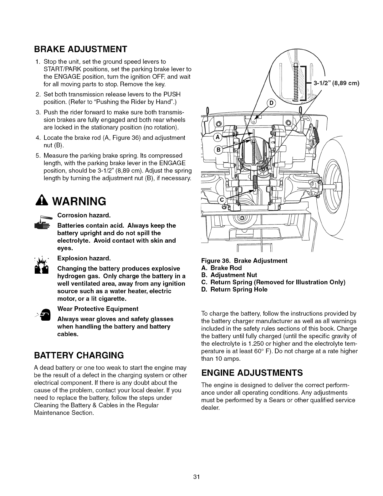
BRAKE ADJUSTMENT
1. Stop the unit, set the ground speed levers to
START/PARK positions, set the parking brake lever to
the ENGAGE position, turn the ignition OFF, and wait
for all moving parts to stop. Remove the key.
2. Set both transmission release levers to the PUSH
position. (Refer to "Pushing the Rider by Hand".)
3. Push the rider forward to make sure both transmis-
sion brakes are fully engaged and both rear wheels
are locked in the stationary position (no rotation).
4. Locate the brake rod (A, Figure 36) and adjustment
nut (B).
5. Measure the parking brake spring. Its compressed
length, with the parking brake lever in the ENGAGE
position, should be 3-1/2" (8,89 cm). Adjust the spring
length by turning the adjustment nut (B), if necessary.
3-1/2" (8,89 cm)
WARNING
Corrosion hazard.
Batteries contain acid. Always keep the
battery upright and do not spill the
electrolyte. Avoid contact with skin and
eyes.
Explosion hazard.
Changing the battery produces explosive
hydrogen gas. Only charge the battery in a
well ventilated area, away from any ignition
source such as a water heater, electric
motor, or a lit cigarette.
Wear Protective Equipment
Always wear gloves and safety glasses
when handling the battery and battery
cables.
BATTERY CHARGING
A dead battery or one too weak to start the engine may
be the result of a defect in the charging system or other
electrical component. If there is any doubt about the
cause of the problem, contact your local dealer. If you
need to replace the battery, follow the steps under
Cleaning the Battery & Cables in the Regular
Maintenance Section.
Figure 36. Brake Adjustment
A. Brake Rod
B. Adjustment Nut
C. Return Spring (Removed for Illustration Only)
D. Return Spring Hole
To charge the battery, follow the instructions provided by
the battery charger manufacturer as well as all warnings
included in the safety rules sections of this book. Charge
the battery until fully charged (until the specific gravity of
the electrolyte is 1.250 or higher and the electrolyte tem-
perature is at least 60° F). Do not charge at a rate higher
than 10 amps.
ENGINE ADJUSTMENTS
The engine is designed to deliver the correct perform-
ance under all operating conditions. Any adjustments
must be performed by a Sears or other qualified service
dealer.
31
MOWER DECK LEVELING
ADJUSTMENTS
WARNING
Before adjusting the mower, turn the mower
blades OFF, turn the ignition switch OFF, remove
the key, and allow all moving parts to stop.
Disconnect the spark plug wire and fasten it away
from the spark plug.
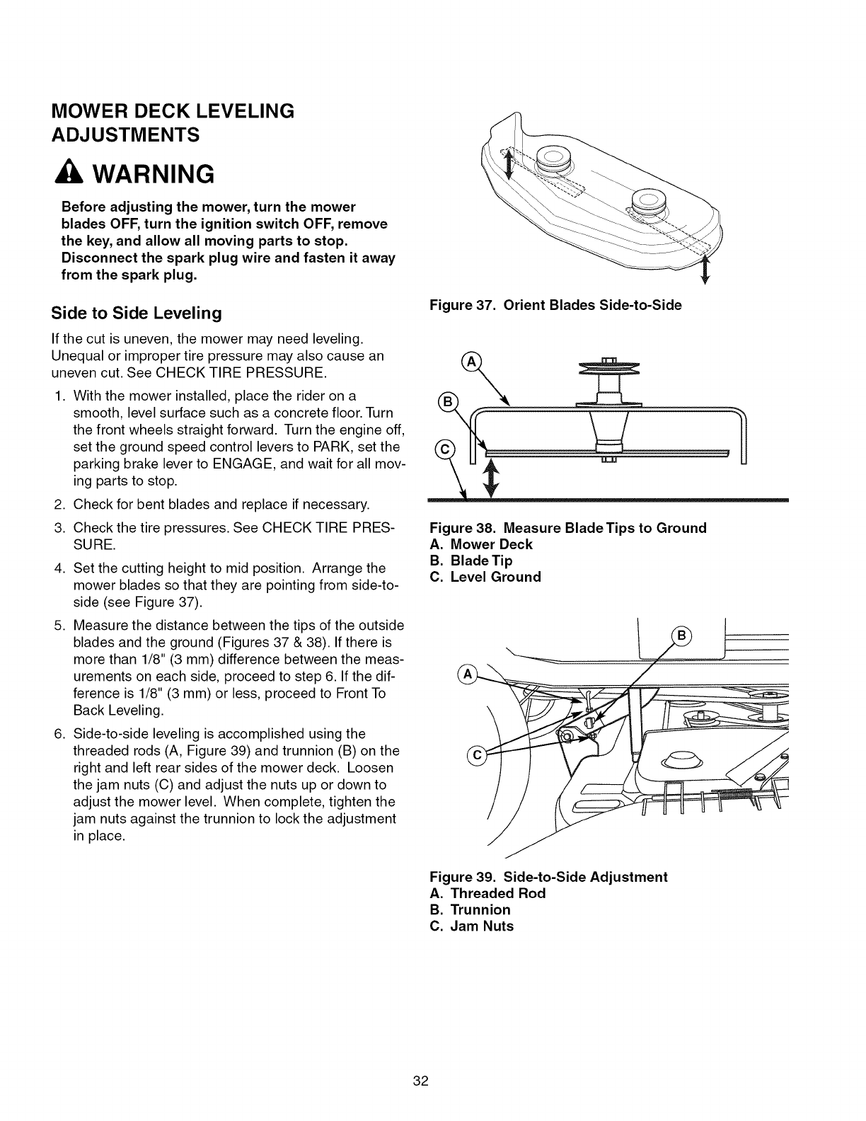
Side to Side Leveling
If the cut is uneven, the mower may need leveling.
Unequal or improper tire pressure may also cause an
uneven cut. See CHECK TIRE PRESSURE.
1. With the mower installed, place the rider on a
smooth, level surface such as a concrete floor. Turn
the front wheels straight forward. Turn the engine off,
set the ground speed control levers to PARK, set the
parking brake lever to ENGAGE, and wait for all mov-
ing parts to stop.
2. Check for bent blades and replace if necessary.
3. Check the tire pressures. See CHECK TIRE PRES-
SURE.
4. Set the cutting height to mid position. Arrange the
mower blades so that they are pointing from side-to-
side (see Figure 37).
5. Measure the distance between the tips of the outside
blades and the ground (Figures 37 & 38). If there is
more than 1/8" (3 mm) difference between the meas-
urements on each side, proceed to step 6. If the dif-
ference is 1/8" (3 mm) or less, proceed to Front To
Back Leveling.
6. Side-to-side leveling is accomplished using the
threaded rods (A, Figure 39) and trunnion (B) on the
right and left rear sides of the mower deck. Loosen
the jam nuts (C) and adjust the nuts up or down to
adjust the mower level. When complete, tighten the
jam nuts against the trunnion to lock the adjustment
in place.
Figure 37. Orient Blades Side-to-Side
Figure 38. Measure Blade Tips to Ground
A. Mower Deck
B. Blade Tip
C. Level Ground
Figure 39. Side-to-Side Adjustment
A. Threaded Rod
B. Trunnion
C. Jam Nuts
32
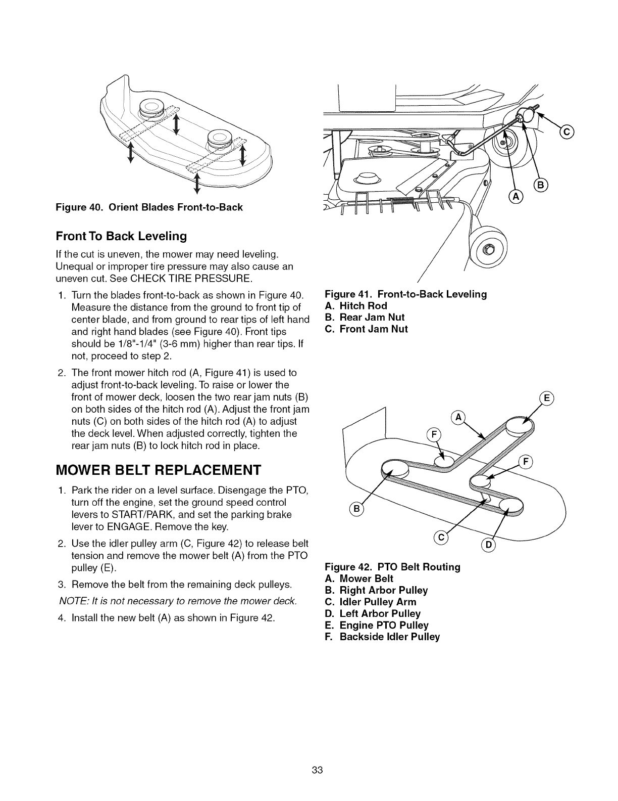
Figure 40. Orient Blades Front-to-Back
Front To Back Leveling
If the cut is uneven, the mower may need leveling.
Unequal or improper tire pressure may also cause an
uneven cut. See CHECK TIRE PRESSURE.
1. Turn the blades front-to-back as shown in Figure 40.
Measure the distance from the ground to front tip of
center blade, and from ground to rear tips of left hand
and right hand blades (see Figure 40). Front tips
should be 1/8"-1/4" (3-6 mm) higher than rear tips. If
not, proceed to step 2.
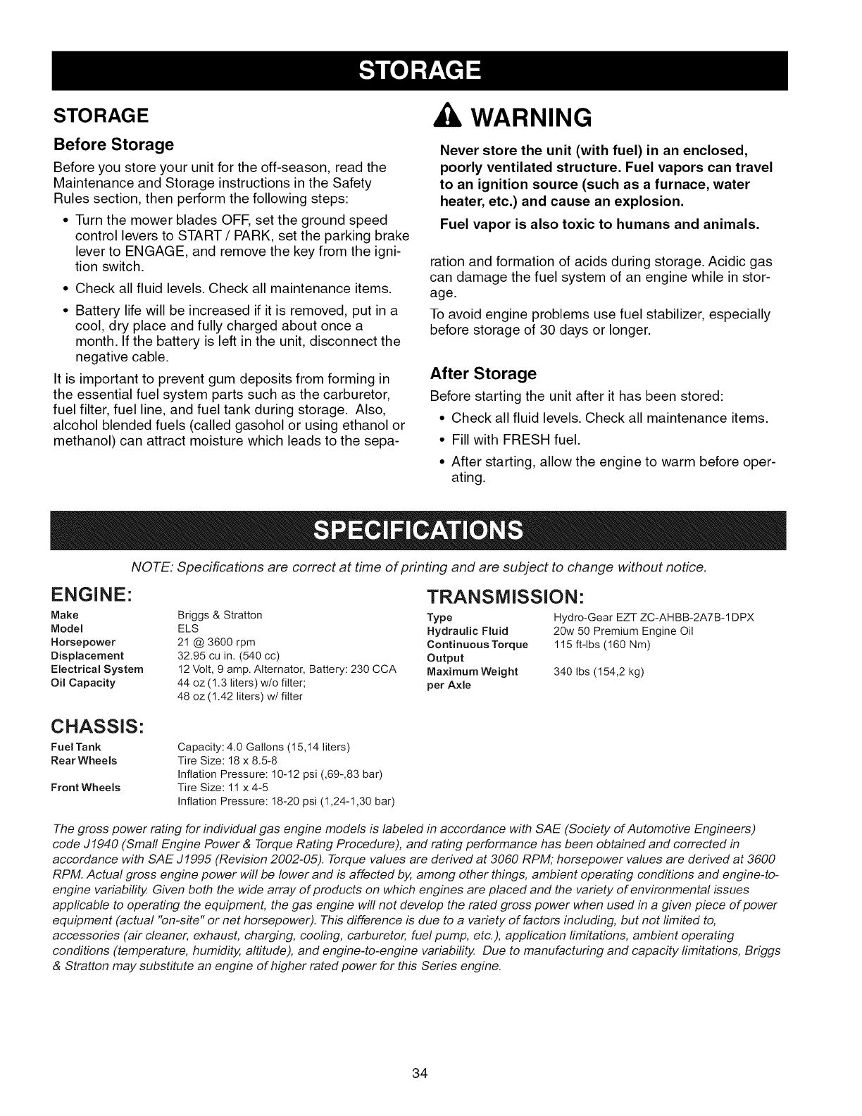
2. The front mower hitch rod (A, Figure 41) is used to
adjust front-to-back leveling. To raise or lower the
front of mower deck, loosen the two rear jam nuts (B)
on both sides of the hitch rod (A). Adjust the front jam
nuts (C) on both sides of the hitch rod (A) to adjust
the deck level. When adjusted correctly, tighten the
rear jam nuts (B) to lock hitch rod in place.
MOWER BELT REPLACEMENT
1. Park the rider on a level surface. Disengage the PTO,
turn off the engine, set the ground speed control
levers to START/PARK, and set the parking brake
lever to ENGAGE. Remove the key.
2. Use the idler pulley arm (C, Figure 42) to release belt
tension and remove the mower belt (A) from the PTO
pulley (E).
3. Remove the belt from the remaining deck pulleys.
NOTE: It is not necessary to remove the mower deck.
4. Install the new belt (A) as shown in Figure 42.
Figure 41. Front-to-Back Leveling
A. Hitch Rod
B. Rear Jam Nut
C. Front Jam Nut
Figure 42. PTO Belt Routing
A. Mower Belt
B. Right Arbor Pulley
C. Idler Pulley Arm
D. Left Arbor Pulley
E. Engine PTO Pulley
F. Backside Idler Pulley
33
STORAGE
Before Storage
Before you store your unit for the off-season, read the
Maintenance and Storage instructions in the Safety
Rules section, then perform the following steps:
• Turn the mower blades OFF, set the ground speed
control levers to START /PARK, set the parking brake
lever to ENGAGE, and remove the key from the igni-
tion switch.
• Check all fluid levels. Check all maintenance items.
Battery life will be increased if it is removed, put in a
cool, dry place and fully charged about once a
month. If the battery is left in the unit, disconnect the
negative cable.
It is important to prevent gum deposits from forming in
the essential fuel system parts such as the carburetor,
fuel filter, fuel line, and fuel tank during storage. Also,
alcohol blended fuels (called gasohol or using ethanol or
methanol) can attract moisture which leads to the sepa-
WARNING
Never store the unit (with fuel) in an enclosed,
poorly ventilated structure. Fuel vapors can travel
to an ignition source (such as a furnace, water
heater, etc.) and cause an explosion.
Fuel vapor is also toxic to humans and animals.
ration and formation of acids during storage. Acidic gas
can damage the fuel system of an engine while in stor-
age.
To avoid engine problems use fuel stabilizer, especially
before storage of 30 days or longer.
After Storage
Before starting the unit after it has been stored:
• Check all fluid levels. Check all maintenance items.
• Fill with FRESH fuel.
• After starting, allow the engine to warm before oper-
ating.
NOTE: Specifications are correct at time of printing and are subject to change without notice.
ENGINE:
Make
Model
Horsepower
Displacement
Electrical System
Oil Capacity
Briggs & Stratton
ELS
21 @ 3600 rpm
32.95 cu in. (540 cc)
12 Volt, 9 amp. Alternator, Battery: 230 CCA
44 oz (1.3 liters) w/o filter;
48 oz (1.42 liters) w/filter
TRANSlVlISSION:
Type Hydro-Gear EZT ZC-AHBB-2A7B-1DPX
Hydraulic Fluid 20w 50 Premium Engine Oil
Continuous Torque 115 ft-lbs (160 Nm)
Output
Maximum Weight 340 Ibs (154,2 kg)
per Axle
CHASSIS:
Fuel Tank
Rear Wheels
Front Wheels
Capacity: 4.0 Gallons (15,14 liters)
Tire Size: 18 x 8.5-8
Inflation Pressure: 10-12 psi (,69-,83 bar)
Tire Size: 11 x 4-5
Inflation Pressure: 18-20 psi (1,24-1,30 bar)
The gross power rating for individual gas engine models is labeled in accordance with SAE (Society of Automotive Engineers)
code J1940 (Small Engine Power & Torque Rating Procedure), and rating performance has been obtained and corrected in
accordance with SAE J1995 (Revision 2002-05). Torque values are derived at 3060 RPM; horsepower values are derived at 3600
RPM. Actual gross engine power will be lower and is affected by, among other things, ambient operating conditions and engine-to-
engine variability, Given both the wide array of products on which engines are placed and the variety of environmental issues
applicable to operating the equipment, the gas engine will not develop the rated gross power when used in a given piece of power
equipment (actual "on-site" or net horsepower). This difference is due to a variety of factors including, but not limited to,
accessories (air cleaner, exhaust, charging, cooling, carburetor, fuel pump, etc.), application limitations, ambient operating
conditions (temperature, humidity, altitude), and engine-to-engine variability, Due to manufacturing and capacity limitations, Briggs
& Stratton may substitute an engine of higher rated power for this Series engine.
34

Whilenormalcareandregularmaintenancewillextend
thelifeofyourequipment,prolongedorconstantuse
mayeventuallyrequirethatservicebeperformedtoallow
ittocontinueoperatingproperly.Thetroubleshooting
guidebelowliststhemostcommonproblems,theircaus-
esandremedies.
Ifyouprefer,alloftheseprocedurescanbeperformed
foryoubya SearsParts& RepairCenter.Seetheback
coverforimportantSearsParts&RepairCenterinforma-
tion.
AWARNING
To avoid serious injury, perform maintenance on
the rider or mower only when the engine is
stopped and the ground speed levers are set to
PARK.
Always remove the ignition key, disconnect the
spark plug wire and fasten it away from the plug
before beginning the maintenance, to prevent
accidental starting of the engine.
Troubleshooting the Rider
PROBLEM CAUSE REMEDY
Engine will Ground speed levers not set to START/PARK. Set to START/PARK.
not turnover Mower blade switch in ON position. Place in OFF position.
or start. Ground speed levers not set to START/PARK. Set to START/PARK.
Choke not in CLOSED position. Move choke to CLOSED position.
L
Ignition switch not turned fully to START position. Turn ignition switch fully to START position.
IOut of fuel. Allow engine to cool, then refill the fuel tank.
iEngine flooded. Set choke to OPEN position when cranking engine.
Fuel is old or stale, or water in fuel. Drain fuel & replace with fresh fuel. Contact Sears
Parts & Repair.
iBattery terminals require cleaning. Clean the battery terminals.
IBattery discharged or dead. Recharge or replace.
Spark plug(s) faulty, fouled or incorrectly gapped. Clean and gap or replace.
iWiring loose or broken. Visually check wiring & replace broken or frayed
wires. Tighten loose connections.
ISolenoid or starter motor faulty. Replace. Contact Sears Parts & Repair.
iSafety interlock switch faulty. Replace. Contact Sears Parts & Repair.
Engine starts iAir filter plugged. Service pre=cleaner and/or replace air filter
hard or runs element.
poorly. Choke not set to CLOSED position when Set choke to CLOSED when cranking. Set choke to
icranking the engine, OR choke not set to OPEN OPEN when engine is running. Awarm engine may
after engine starts, not require choking.
Spark plug faulty, fouled, or incorrectly gapped. Clean and gap or replace.
Engine Low oil level. Check/add oil as required.
knocks, iUsing wrong grade oil. See "Change Engine Oil" in the Maintenance
Section.
Excessive oil iEngine running too hot. Clean engine cooling fins, blower screen and air
consumption, cleaner.
iUsing wrong weight oil. See "Change Engine Oil" in the Maintenance
Section.
Too much oil in crankcase. Drain excess oil.
Engine iDirty air filter or pre-cleaner, or both. Service or replace as required. See Maintenance
exhaust is Section.
black. Choke set to CLOSED when engine is running. Set choke to OPEN as soon as engine starts.
35

Engineruns,but TransmissionreleaseleversinPUSH Moveleversto DRIVEpositions.
rider will not 9ositions.
drive. Drive belt slips, Clean or replace belt as necessary,
Belt is broken, Replace drive belt, Contact Sears Parts & Repair,
Parking brake is not fully released, Contact Sears Parts & Repair,
Rider drive belt Pulleys or belt greasy or oily, Clean as required,
slips. Belt stretched or worn. Replace belt. Contact Sears Parts & Repair.
Parking brake Parking brake is incorrectly adjusted, See Service & Adjustments Section,
will not hold.
Rider steers or Improper tire inflation. See Maintenance Section.
handles poorly. Steering linkage is loose, Check and tighten any loose connections,
Rider tracks to Ground speed adj. knobs not adjusted, See SPEED BALANCING ADJUSTMENT in Service &
one side. Adjustments section,
Troubleshooting the Mower
PROBLEM CAUSE REMEDY
Mower cutting Cutting height motor screw dirty or requires Thoroughly clean and lubricate cutting height motor
height does not lube. screw,
adjust. Cutting height linkage disconnected, Check that mower linkage is connected,
Mower cut is Rider tires not inflated equally or properly. See Maintenance Section.
uneven. Mower not leveled properly, See "Mower Leveling" in Service & Adjustments,
Mower cut is Engine speed too slow, Always set engine speed to FAST when mowing,
rough looking. Ground speed too fast, Decrease ground speed,
Blades are dull, Sharpen or replace blades, See Maintenance
Section,
Mower drive belt slipping because it is oily or Clean or replace belt as necessary,
worn.
Blades not properly fastened to arbors. See "Check/Replace Mower Blades" in Maintenance
Section.
Engine stalls Engine speed too slow. Always set engine speed to FAST when mowing.
easily with Ground speed too fast, Decrease Ground Speed,
mower engaged. Cutting height set too low. Cut tall grass at maximum cutting height during first
9ass.
Underside of mower deck dirty, Remove mower deck and clean underside,
Discharge chute jamming with cut grass, Cut grass with discharge pointing toward previously
cut area,
Excessive Blade mounting nuts are loose, Tighten to 80-90 ft-lbs (108-122 Nm).
mower Mower blades, arbors, or pulleys are bent, Check and replace as necessary,
vibration, Mower blades are out of balance, Replace or balance blades, See Maintenance
Section,
Belt installed incorrectly, Reinstall correctly,
Mower drive belt Idler pulley spring broken or not properly Repair or replace as needed,
slips or fails to attached,
drive, Mower drive belt broken, Replace drive belt,
PTO clutch out of adjustment, Adjust PTO clutch, See Maintenance Section,
36

anual Del Due o
®
ZTS
Gire a cero los montables posteriores del motor con el
arranque el6ctrico
No. de modelo
107.289860 (:21HP Briggs & Stratton Engine con segadora de 42")
PRECAUCION: Este producto tiene un mot
or con expulsi6n baja el cual funciona difer-
entemente a otros motores. Antes que
arranque el motor, lea y comprenda el
Manual del DueSo.
Para obtener respuestas a cualquier pregunta
sobre este producto, flame al num6ro de tel6-
fono-(sin cobro) siguiente:
1-800-659-5917
Servicio de ayuda Sears Craftsman
5 am- 5 pm, Lunes a Sabado

38
Declaracibn de Garantia ........................................... 39
Reglas eInformacibn de Seguridad ........................ 40
Ndmeros de Identificacibn ........................................ 45
Montaje ....................................................................... 46
Pre-Operacibn ............................................................ 49
Operacibn ................................................................... 50
Mantenimiento ........................................................... 57
EeServicio y Ajustes ................................................. 66
Almacenamiento ........................................................ 70
Especificaciones ....................................................... 70
Diagnbstico ................................................................ 71
Partes de Refaccibn ............................................ PTS-1
Hardware y Especificaciones del Esfuerzo de
Torsibn .............................................................. PTS-39
Repare El Acuerdo de la
Proteccibn .................. Dentro De la Cubierta Trasera
Mantenga Los N_meros De
Phono ............................................... Cubierta Trasera
NOTA: En este manual, "izquierda" y"derecha" se refieren seg#n come se vea desde la posicidn de operacidn.
GARANT|A COMPLETA DE FABRICACION
Cuando se opera y mantiene de acuerdo con todas las instrucciones que se proporcionan, si alguna pieza no ampliable
de este equipo falla debido a un defecto en los materiales o en la fabricaci6n dentro de dos a_os desde la fecha de
compra, Ilame a 1-800-659-5917 para solicitar una reparaci6n gratuita en su hogar.
La cubierta y el eje delantero se repararan de manera gratuita durante cinco a_os desde la fecha de compra si se trata
de un defecto de material o de fabricaci6n.
La cobertura de la garanfia anterior se aplica solo durante 90 dfas desde la fecha de compra si este equipo se usa algu-
na vez con prop6sitos comerciales o de arriendo.
En todos los casos, si la reparaci6n no es posible, el equipo se reemplazara de manera gratuita con el mismo modelo o
un modelo equivalente.
La baterfa se reemplazara de manera gratuita durante 90 dfas desde la fecha de compra si es defectuosa en los materi-
ales o en la fabricaci6n (nuestra prueba comprueba que no mantiene carga).
Esta garanfia SOLAMENTE cubre defectos de material y fabricaci6n. Sears NO pagara:
• Arficulos prescindibles que se gasten durante el uso normal, entre los que figuran, entre otros, aspas, bujfas, purifi-
cadores de aire, correas y filtros de aceite.
• Servicio de mantenimiento normal, cambios de aceite o afinamientos.
• Reemplazo o reparaci6n de neum_.ticos debido a pinchazos por objetos exteriores, como clavos, espinas, tocones o
vidrio.
• Reemplazo o reparaci6n de neum_.ticos o ruedas producto de desgaste, accidentes, o mantenimiento o fun-
cionamiento inadecuados.
• Reparaciones necesarias debido a abuso del operador, incluidos, entre otros, da_os provocados por remolcar objetos
que sobrepasen la capacidad del equipo, impactos a objetos que doblen el bastidor o cig0e_al, o sobrepasar la
velocidad del motor.
• Reparaciones necesarias debido a negligencia del operador, incluidos, entre otros, da_os mec_.nicos o electricos
provocados por almacenamiento inadecuado, no utilizar el tipo o la cantidad correcta de aceite de motor, no mantener
la cubierta libre de desperdicios inflamables o no mantener al equipo de acuerdo con las instrucciones que se
incluyen en el manual del operador.
• Reparaciones o limpiezas al motor (sistema de combustible) provocadas por combustible que se determine contami-
nado u oxidado (deteriorado). En general, se debe utilizar el combustible dentro de 30 dfas a partir de la fecha de
compra.
• Desgaste y deterioro normal de los acabados exteriores o reemplazo de la etiqueta del producto.
Esta garanfia s61ose aplica mientras este producto este dentro de los Estados Unidos.
Esta garanfia le otorga derechos legales especfficos, y Vd. puede ostentar otros derechos, que pueden variar de estado
en estado.
Sears, Roebuck and Co., Hoffman Estates, IL 60179
39
Leaestasreglasdeseguridady sigalasconcuidado.Noobedecerestasreglaspuedeocasionarlaperdida
delcontrolsobrelaunidad,lesionesseverasa lapersonao lamuertedeusted,o espectadores,odaSosa la
o alequipo.Esta cubierta de la podadora es capaz de amputar manos y pies y de arrojar
objetos. El tri&ngulo_, en el texto denota precauciones o advertencias importantes que deben obedecerse.
OPERACION GENERAL
1. Lea, entienda y siga todas las instrucciones en el manual y
en la unidad antes de arrancar.
2. No coloque las manos o pies cerca de las partes giratorias o
debajo de la maquina. Mant6ngase alejado de la abertura
de expulsi6n en todo momento.
3. $61o permita que un adulto responsable, que est6 familiariza-
do con las instrucciones, opere la unidad (los reglamentos
locales pueden restringir la edad del operador).
4. Retire del Area objetos tales como piedras, juguetes, etc.,
que pueden ser cogidos y arrojados por las aspas.
5. AsegQrese de que el Area est6 libre de otra gente antes de
podar el c_sped. Detenga la unidad si alguien entra en el
Area.
6. Nunca Ileve pasajeros.
7. No pode el c_sped en reversa a menos que sea absoluta-
mente necesario. Siempre mire hacia abajo y hacia atras
antes de echarse en reversa y mientras Io hace.
8. Nunca descargue el material directamente hacia alguien.
Evite descargar el material contra una pared u obstrucci6n.
El material puede rebotar hacia el operador. Detenga las
aspas cuando cruce por superficies cubiertas de grava.
9. No opere la maquina sin el recogedor completo de hierba,
guarda de descarga (deflector) ni otros dispositivos de
seguridad en su lugar y operacionales.
10. Baje la velocidad antes de dar la vuelta.
11. Nunca deje la unidad operando sin supervlsi6n. Siempre
desacople las cuchillas (PTO), ponga el freno de mano,
detenga el motor y quite las Ilaves antes de desmontar.
12. Desacople las cuchillas (PTO) cuando no est6 podando el
c_sped. Apague el motor y espere a que todas las partes
se detengan por completo antes de limpiar la maquina,
quitar el recolector de hierba o desatascar la guarda de la
descarga.
13. Opere la maquina s61o a la luz del dia o con buena luz arti-
ficial.
14. No opere la unidad si usted esta bajo la influencia de alco-
hol o drogas.
15. Tenga cuidado con el trafico si opera cerca de alguna calle.
16. Sea extremadamente cuidadoso al cargar o descargar la
unidad en un remolque o camioneta.
17. Siempre prot6jase los ojos cuando opere esta unidad.
18. Los datos indican que operadores, de 60 afios y mas, estan
involucrados en un gran porcentaje de lesiones asociadas
con equipos motorizados. Estos operadores deberian eval-
uar su habilidad de operar el equipo con la suficiente
seguridad para protegerse a si mismos y a otros de
lesiones.
19. Siga las recomendaciones del fabricante respecto a los
pesos y contrapesos para Ilantas.
20. Recuerde que el operador es responsable de los acci-
dentes que ocurran a otra gente o propiedad.
21. Todos los conductores deberian pedir y obtener instruc-
ciones profesionales y practicas.
22. Siempre use zapatos cerrados y pantalones. Nunca opere
la unidad descalzo o usando sandalias.
23. Antes de su uso, siempre verifique visualmente que las
cuchillas y sus aditamentos est6n presentes, intactos y afi-
anzados. Reemplace las partes dafiadas o desgastadas.
24. Desacople los accesorios antes de: cargar combustible,
retirar un accesorio, hacer ajustes (a menos de que el
ajuste pueda hacerse desde el puesto del operador).
25. Cuando la maquina esta estacionada, almacenada o se
deja sin supervisi6n, baje los medios de corte a menos de
que use una traba mecanica positiva.
26. Antes de dejar el puesto del operador por cualquier raz6n,
accione el freno de mano (si viene equipado con uno),
desacople las cuchillas (PTO), detenga el motor y quite la
Ilave.
27. Para reducir el peligro de incendio, mantenga la unidad libre
de c_sped, hojas y aceite excesivo. No se detenga ni esta-
cione sobre hojas secas, c_sped o materiales com-
bustibles.
28. Usar u operar un motor sobre o cerca de tierras cubiertas
de bosques, matorrales o c_sped es una violaci6n de la
Secci6n 4442 del C6digo de Recursos PQblicos de
California a menos que el sistema de escape est6 equipa-
do con un parachispas que cumpla con las leyes locales o
estatales aplicables. Es posible que otras Areas estatales o
federales tengan leyes similares.
29. Las regulaciones del OSHA pueden requerir el uso de la
protecci6n de oido cuando estan expuestas a los niveles de
sonido mayor DBA de 85 por un periodo de 8 horas.
CAUTION
O sta maquina produce niveles de sonido en el
exceso de DBA 85 en el oido del operador y puede
causar periodos sin embargo prolongados de la
p_rdida de oido de la exposici6n.
Protecci6n de oido del desgaste al funcionar esta maquina.
TRANSPORTE Y ALMACENAMIENTO
1. Cuando se transporta la unidad sobre un remolque abierto,
asegQrese de que mire hacia el frente, en direcci6n del
desplazamiento. Si la unidad esta mirando hacia atras, la
fuerza del aire puede dafiar la unidad.
2. Siempre obedezca las practicas seguras para cargar com-
bustible y manejar combustible al cargar la unidad con
combustible despu6s del transporte o almacenamiento.
3. Nunca almacene la unidad (con combustible) en una estruc-
tura cerrada con poca ventilaci6n. Los vapores del com-
bustible pueden viajar a una fuente de ignici6n (como un
horno, calentador de agua, etc.) y ocasionar una explosi6n.
Los vapores del combustible tambi_n son t6xicos para los
humanos y animales.
4. Siempre siga las instrucciones del manual del motor respec-
to a las preparaciones de almacenamiento antes de alma-
cenar la unidad ya sea por periodos cortos o largos.
5. Siempre siga las instrucciones del manual del motor respec-
to a los procedimientos apropiados de arranque cuando
reintegre la unidad al servicio.
6. Nunca almacene la unidad ni el contenedor de combustible
en un lugar cerrado, donde haya una llama abierta o piloto,
como sucede con un calentador de agua. Permita que la
unidad se enfrie antes de almacenarla.
40
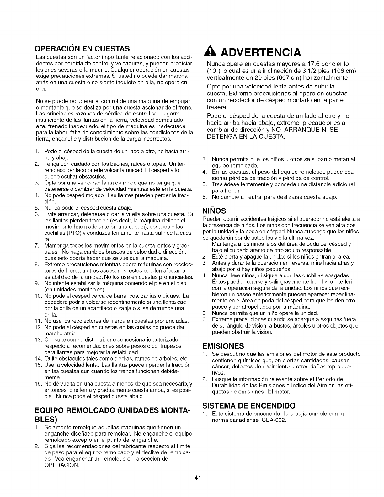
OPERACION EN CUESTAS
Las cuestas son un factor importante relacionado con los acci-
dentes por p@dida de control y volcaduras, y pueden propiciar
lesiones severas o la muerte. Cualquier operaci6n en cuestas
exige precauciones extremas. Si usted no puede dar marcha
atras en una cuesta o se siente inquieto en ella, no opere en
ella.
No se puede recuperar el control de una maquina de empujar
o montable que se desliza por una cuesta accionando el freno.
Las principales razones de p@dida de control son: agarre
insuficiente de las Ilantas en la tierra, velocidad demasiado
alta, frenado inadecuado, el tipo de maquina es inadecuada
para la labor, falta de conocimiento sobre las condiciones de la
tierra, enganche y distribuci6n de la carga incorrectos.
ADVERTENCIA
Nunca opere en cuestas mayores a 17.6 pot ciento
(10°) Io cual es una inclinaci6n de 3 1/2 pies (106 cm)
verticalmente en 20 pies (607 cm) horizontalmente
Opte pot una velocidad lenta antes de subir la
cuesta. Extreme precauciones al opere en cuestas
con un recolector de cesped montado en la parte
trasera.
Pode el cesped de la cuesta de un lado al otto y no
hacia arriba hacia abajo, extreme precauciones al
cambiar de direcci6n y NO ARRANQUE NI SE
DETENGA EN LA CUESTA.
1. Pode el c_sped de la cuesta de un lado a otro, no hacia arri-
bay abajo.
2. Tenga con cuidado con los baches, raices o topes. Un ter-
reno accidentado puede volcar la unidad. El c_sped alto
puede ocultar obstaculos.
3. Opte por una velocidad lenta de modo que no tenga que
detenerse o cambiar de velocidad mientras est6 en la cuesta.
4. No pode c_sped mojado. Las Ilantas pueden perder la trac-
ci6n.
5. Nunca pode el c_sped cuesta abajo.
6. Evite arrancar, detenerse o dar la vuelta sobre una cuesta. Si
las Ilantas pierden tracci6n (es decir, la maquina detiene el
movimiento hacia adelante en una cuesta), desacople las
cuchillas (PTO) y conduzca lentamente hasta salir de la cues-
ta.
7. Mantenga todos los movimientos en la cuesta lentos y grad-
uales. No haga cambios bruscos de velocidad o direcci6n,
pues esto podria hacer que se vuelque la maquina.
8. Extreme precauciones mientras opere maquinas con recolec-
tores de hierba u otros accesorios; _stos pueden afectar la
estabilidad de la unidad. No los use en cuestas pronunciadas.
9. No intente estabilizar la maquina poniendo el pie en el piso
(en unidades montables).
10. No pode el c_sped cerca de barrancos, zanjas o diques. La
podadora podria volcarse repentinamente si una Ilanta cae
por la orilla de un acantilado o zanja o si se derrumba una
orilla.
11. No use los recolectores de hierba en cuestas pronunciadas.
12. No pode el c_sped en cuestas en las cuales no pueda dar
marcha atras.
13. Consulte con su distribuidor o concesionario autorizado
respecto a recomendaciones sobre pesos o contrapesos
para Ilantas para mejorar la estabilidad.
14. Quite obstaculos tales como piedras, ramas de arboles, etc.
15. Use la velocidad lenta. Las Ilantas pueden perder la tracci6n
en las cuestas aun cuando los frenos funcionan debida-
mente.
16. No d_ vuelta en una cuesta a menos de que sea necesario, y
entonces, gire lenta y gradualmente cuesta arriba, si es posi-
ble. Nunca pode el c_sped cuesta abajo.
EQUIPO REMOLCADO (UNIDADES MONTA-
BLES)
1. Solamente remolque aquellas maquinas que tienen un
enganche diseSado para remolcar. No enganche el equipo
remolcado excepto en el punto del enganche.
2. Siga las recomendaciones del fabricante respecto al limite
de peso para el equipo remolcado y el declive de remolca-
do. Vea enganchar un remolque en la secci6n de
OPERACION.
3. Nunca permita que los niSos u otros se suban o metan al
equipo remolcado.
4. En las cuestas, el peso del equipo remolcado puede oca-
sionar p@dida de tracci6n y p@dida de control.
5. Trasladese lentamente y conceda una distancia adicional
para frenar.
6. No cambie a neutral para deslizarse cuesta abajo.
NIQOS
Pueden ocurriraccidentestragicossieloperadorno estaalertaa
lapresenciade niSos.Los niSoscon frecuenciase ven atraidos
porlaunidady lapoda de c_sped.Nunca suponga que losniSos
se quedarandonde ustedlosviolaQltimavez.
I. Mantenga a losniSoslejosdelAreade poda delc_sped y
bajoelcuidadoatentode otroadultoresponsable.
2. Est6alertay apague launidadsilosniSosentranalArea.
3. Antes y durante la operaci6n en reversa, mire hacia atras y
abajo por si hay niSos pequeSos.
4. Nunca Ileve niSos, ni siquiera con las cuchillas apagadas.
12stospueden caerse y salir gravemente heridos o interferir
con la operaci6n segura de la unidad. Los niSos que reci-
bieron un paseo anteriormente pueden aparecer repentina-
mente en el Area de poda del c_sped para que les den otro
paseo y ser atropellados por la maquina.
5. Nunca permita que un niSo opere la unidad.
6. Extreme precauciones cuando se acerque a esquinas fuera
de su angulo de visi6n, arbustos, arboles u otros objetos que
pueden obstruir la visi6n.
EMISIONES
1. Se descubri6 que las emisiones del motor de este producto
contienen quimicos que, en ciertas cantidades, causan
cancer, defectos de nacimiento u otros daSos reproduc-
tivos.
2. Busque la informaci6n relevante sobre el Periodo de
Durabilidad de las Emisiones e Indice del Aire en las eti-
quetas de emisiones del motor.
SISTEMA DE ENCENDIDO
1. Este sistema de encendido de la bujia cumple con la
norma canadiense ICEA-002.
41
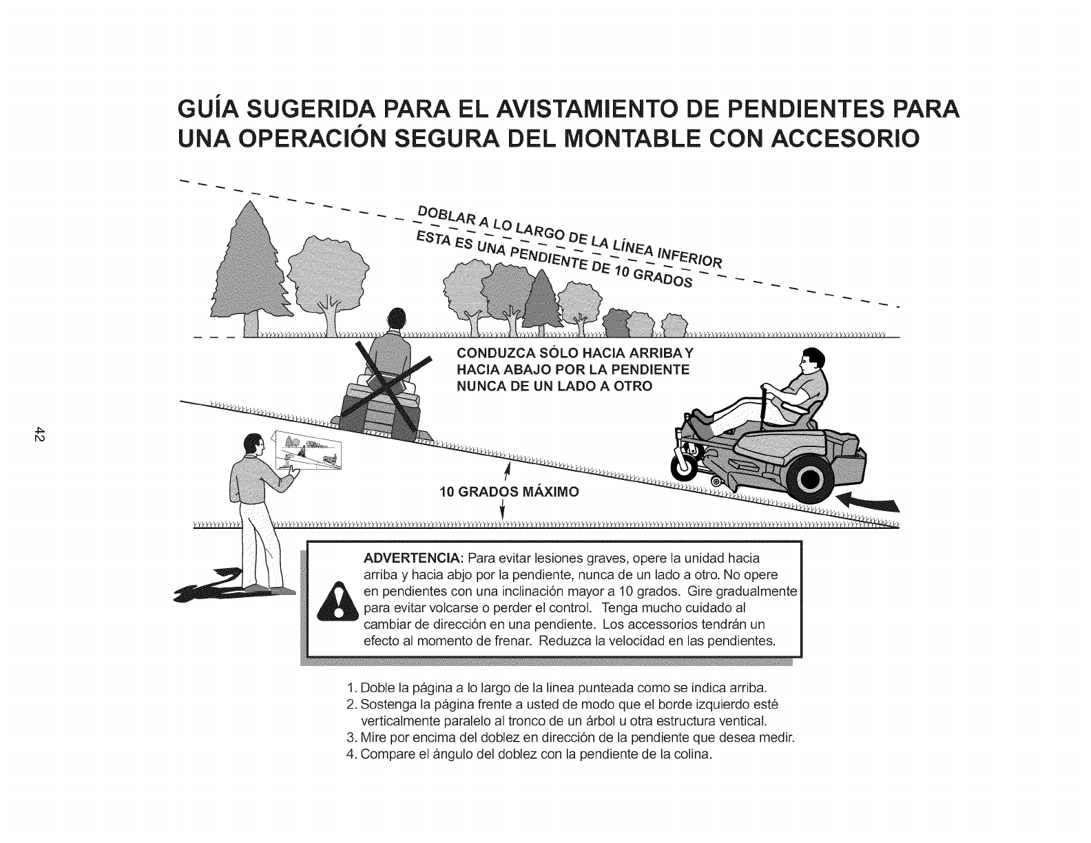
GUJA SUGERIDA PARA EL AVISTAMIENTO DE PENDIENTES PARA
UNA OPERACION SEGURA DEL MONTABLE CON ACCESORIO
DOBLAR A LO LARGo DE LA
IENTE "D 10
CONDUZCA SOLO HACIA ARRIBAY
HACIA ABAJO POR LA PENDIENTE
NUNCA DE UN LADO A OTRO
ro
10 GRADOS MAXIMO
ADVERTENCIA: Para evitar lesiones graves, opere la unidad hacia
arriba y hacia abjo por la pendiente, nunca de un lado a otro. No opere
en pendientes con una inclinaci6n mayor a 10 grados. Gire gradualmente
para evitar volcarse o perder el control. Tenga mucho cuidado al
cambiar de direcci6n en una pendiente. Los accessorios tendran un
efecto al momento de frenar. Reduzca la velocidad en las pendientes.
1. Doble la pagina a Io largo de la linea punteada como se indica arriba.
2. Sostenga la pagina frente a usted de modo que el borde izquierdo este
verticalmente paralelo al tronco de un arbol u otra estructura ventical.
3. Mire pot encima del doblez en direcci6n de la pendiente que desea medir.
4. Compare el ,¢ngulo del doblez con la pendiente de la colina.
SERVICIO Y MANTENIMIENTO
Manejo Seguro de la Gasolina
1. Apague cigarros, puros, pipas y otras fuentes de ignici6n.
2. Use s61o los contenedores aprobados para gasolina.
3. Nunca quite el tap6n de la gasolina ni cargue combustible
con el motor encendido. Permita que el motor se enfrie
antes de poner combustible.
4. Nunca cargue combustible para la maquina en espacios cer-
rados.
5. Nunca almacene la maquina ni el contenedor de combustible
donde haya una llama abierta, chispa o piloto, como cerca
de un calentador de agua u otro dispositivo.
6. Nunca Ilene los contenedores dentro de un vehiculo o en la
caja de una camioneta con cobertor de plat6n de plastico.
Siempre coloque los contenedores en el piso, lejos de su
vehiculo antes del rellenado.
7. Retire el equipo accionado por gasolina de la camioneta o
remolque y cargue el combustible estando el equipo en el
piso. Si esto no es posible, entonces cargue el combustible
en el equipo colocado en el remolque con un contenedor
portatil, en vez de usar un dispensador de gasolina.
8. Mantenga el dispensador en contacto con la orilla del tanque
de gasolina o con la abertura del contenedor en todo
momento hasta que termine de cargar combustible. No use
un dispensador con un dispositivo de cerrado y abierto.
9. Si derrama combustible sobre la ropa, cambiese de ropa de
inmediato.
10. Nunca Ilene demasiado el tanque de gasolina. Coloque
nuevamente el tap6n de la gasolina y apri_telo fijamente.
11. Extreme precauciones en el manejo de la gasolina y otros
combustibles. Son inflamables y los vapores son explo-
sivos.
12. Si se derrama combustible, no intente arrancar el motor
sino mas bien mueva la maquina lejos del Area de derrame
y evite crear cualquier fuente de ignici6n hasta que se
hayan disipado los vapores del combustible.
13. Vuelva a colocar fijamente las tapas del tanque de gasolina
y las tapas del contenedor del combustible.
Servicio y Mantenimiento
1. Nunca ponga en marcha la unidad en un Area cerrada donde
se pueden acumular los gases del mon6xido de carbono.
2. Mantenga apretadas las tuercas y pernos, en especial los
pernos de ajuste para las cuchillas, y mantenga el equipo
en buenas condiciones.
3. Nunca manipule los dispositivos de seguridad. Verifique su
operaci6n adecuada con regularidad y asegQrese de hacer
las reparaciones necesarias si no funcionan debidamente.
4. Mantenga la unidad libre de c_sped, hojas u otra acumu-
laci6n de despojos. Limpie derrames de aceite o com-
bustible y quite cualquier despojo impregnado de com-
bustible. Siempre permita que su maquina se enfrie antes
de almacenarla.
5. Detenga e inspeccione la maquina, si pega contra un objeto.
Repare, si es necesario, antes de volver a arrancar.
6. Nunca haga ajustes ni reparaciones con el motor encendido.
7. Verifique los componentes del recolector de hierba y la guar-
da de la descarga con frecuencia y reemplacelos con las
partes recomendadas por el fabricante, cuando sea nece-
sario.
8. Las cuchillas de la podadora estan afiladas. Envuelva las
cuchillas o utilice guantes, y extreme precauciones cuando
les d_ mantenimiento.
9. Verifique la operaci6n de los frenos con frecuencia. Ajuste y
d_ mantenimiento segQn se requiera.
10. Mantenga o reemplace las etiquetas de seguridad y de
instrucciones segt]n sea necesario.
11. No quite el filtro de la gasolina cuando el motor esta
caliente ya que la gasolina que se derrame se puede incen-
diar. No extienda las abrazaderas de la tuberia del com-
bustible mas alia de Io necesario. AsegOrese de que las
abrazaderas agarren firmemente la manguera sobre el filtro
despu6s de la instalaci6n.
12. No use gasolina que contenga METANOL, gasohol con mas
del 10% de ETANOL, aditivos para gasolina ni gas blanco
porque podria ocasionar daSos al motor o a la instalaci6n
del combustible.
13. Si debe drenar el tanque de gasolina, debe hacerlo al aire
libre.
14. Reemplace los silenciadores/mofles defectuosos.
15. Mantenga o reemplace las etiquetas de seguridad y de
instrucciones segt]n sea necesario.
16. Use s61o las partes de repuesto autorizadas de fabrica al
reparar la unidad.
17. Siempre acate las especificaciones de fabrica respecto a
todas las disposiciones y ajustes.
18. S61o acuda a lugares autorizados de servicio si requiere de
servicio y reparaciones mayores.
19. Nunca intente hacer reparaciones mayores en esta unidad
a menos que tenga la preparaci6n para ello. Los proced-
imientos inadecuados de mantenimiento pueden ocasionar
peligros en la operaci6n, da_os al equipo y anulaci6n de la
garantia del fabricante.
20. En las podadoras con cuchillas mQltiples, tenga cuidado ya
que hacer girar una cuchilla puede hacer que otras
cuchillas tambi_n giren.
21. No cambie el limitador de velocidad del motor ni acelere
demasiado el motor. Operar el motor a una velocidad exce-
siva puede aumentar los peligros de lesiones a la persona.
22. Desacople los accesorios de conducci6n, detenga el motor,
quite la Ilave y desconecte el cable de la bujia antes de:
desatorar obstrucciones en accesorios y tolvas, dar man-
tenimiento a la unidad, pegarle a un objeto o si la unidad
vibra de modo anormal. Despu_s de pegarle a un objeto,
inspeccione la maquina para ver si fue daSada y haga las
reparaciones antes de volver a arrancar y operar el equipo.
23. Nunca coloque sus manos cerca de las partes en
movimiento, como el ventilador de enfriamiento de la
bomba hidraulicas, cuando la unidad esta encendida. (Los
ventiladores de enfriamiento de las bombas hidraulicas nor-
malmente se encuentran arriba del transeje).
24. Las unidades con bombas hidraulicas, mangueras o
motores: ADVERTENClA: El fluido hidraulico que se fuga
bajo presi6n tiene la suficiente fuerza para penetrar la piel y
ocasionar lesiones graves. Si se inyecta un fluido extraSo
bajo la piel, un m_dico familiar con esta forma de lesi6n
debe sustraerlo quirt]rgicamente en el lapso de unas cuan-
tas horas o puede acabar en gangrena. Mantenga el cuer-
po y las manos lejos de los orificios de regulaci6n o inyec-
tores que expulsan fluido hidraulico bajo alta presi6n. Use
papel o cart6n, y no las manos, para buscar fugas.
AsegQrese de que todas las conexiones del fluido hidrauli-
co estan fijas y que todas las mangueras y lineas hidrauli-
cas est6n en buenas condiciones antes de ejercer presi6n
sobre el sistema. Si hay fugas, mande la unidad de inmedi-
ato a mantenimiento con su distribuidor autorizado.
25. ADVERTENClA: Aparato el_ctrico almacenado. El desen-
ganche indebido de resortes puede ocasionar lesiones
graves a la persona. Los resortes deben ser quitados por
un t6cnico autorizado.
26. Modelos equipados con un radiador para motor: ADVER-
TENClA: Aparato el_ctrico almacenado. Para evitar
lesiones graves al cuerpo por liquido refrigerante caliente o
erupci6n de vapor, nunca intente quitar la tapa del radiador
mientras el motor esta encendido. Detenga el motor y
espere hasta que haya enfriado un poco. Incluso entonces,
extreme precauciones al quitar la tapa.
43
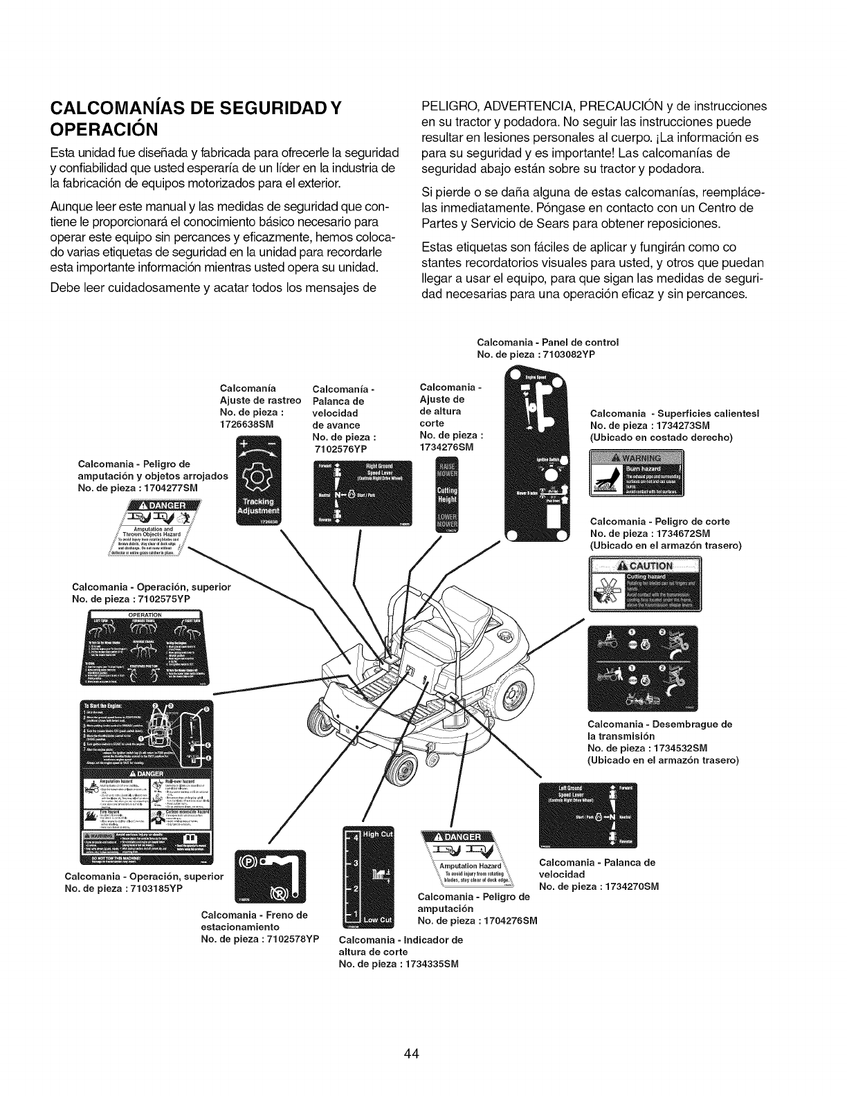
CALCOMANiAS DE SEGURIDAD Y
OPERAClON
Esta unidad fue dise_ada y fabricada para ofrecerle la seguridad
y confiabilidad que usted esperarfa de un Ifder en la industria de
la fabricaci6n de equipos motorizados para el exterior.
Aunque leer este manual y las medidas de seguridad que con-
tiene le proporcionar_t el conocimiento b_tsico necesario para
operar este equipo sin percances y eficazmente, hemos coloca-
do varias etiquetas de seguridad en la unidad para recordarle
esta importante informaci6n mientras usted opera su unidad.
Debe leer cuidadosamente y acatar todos los mensajes de
PELIGRO, ADVERTENCIA, PRECAUCION y de instrucciones
en su tractor y podadora. No seguir las instrucciones puede
resultar en lesiones personales al cuerpo, iLa informaci6n es
para su seguridad yes importante! Las calcomanias de
seguridad abajo est_m sobre su tractor y podadora.
Si pierde o se da_a alguna de estas calcomanias, reempla.ce-
las inmediatamente. P6ngase en contacto con un Centro de
Partes y Servicio de Sears para obtener reposiciones.
Estas etiquetas son f_tciles de aplicar y fungir_m como co
stantes recordatorios visuales para usted, y otros que puedan
Ilegar a usar el equipo, para que sigan las medidas de seguri-
dad necesarias para una operaci6n eficaz y sin percances.
Calcomania - Panel de control
No. de pieza :7103082YP
Calcoman ia Calcoman ia - Calcoman ia -
Ajuste de rastreo Palanca de Ajuste de
No. de pieza : velocidad de altura
1726638SM de avarice corte
No. de pieza : No. de pieza :
7102576YP 1734276SM
Calcomania - Peligro de
amputaci6n y objetos arrojados
No. de pieza : 1704277SM
..,,;i':_ :L-qj _,/'
,_/ Amputation and ¢'
/_ Thrown Objects Hazard ¢_
Calcomania - Operacidn
No. de pieza : 7102575YP
Calcomania - Superficies calientesl
No. de pieza : 1734273SM
(Ubicado en costado derecho)
Calcomania - Peligro de corte
No. de pieza : 1734672SM
(Ubicado en el armaz6n trasero)
._ ............. _ ............ ., ,i_.<,-<:m
Calcomania - Operaci6n, superior
No. de pieza :7103185YP
Calcomania - Freno de
estacionarniento
No. de pieza : 7102578YP
Calcomania - Desernbrague de
la transrnisi6n
No. de pieza : 1734532SM
(Ubicado en el arrnaz6n trasero)
't%,Amputalion Hazard_,, Calcomania -Palanca de
"_ TOavoid injury froni rotatilig '_) velocidad
_"?""'"_t°v'""'°_"°°"'"g_!'_ No. de pieza : 1734270SM
Calcomania - Peligro de
amputaci6n
No. de pieza : 1704276SM
Calcomania - Indicador de
altura de corte
No. de pieza : 1734335SM
44
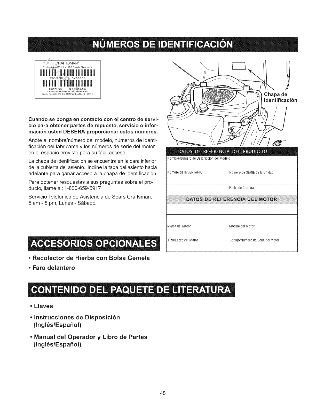
_ j CRAFTSMAN
Iliiid i ,i] l]iiiiiiiii]i iill
Chapa de
Identificaci6n
Cuando se ponga en contacto con el centro de servi-
cio para obtener partes de repuesto, servicio oinfor=
macion usted DEBER_, proporcionar estos n_meros.
Anote el nombre/nOmero del modelo, nt_meros de identi-
ficaci6n del fabricante y los nOmeros de serie del motor
en el espacio provisto para su f_cil acceso.
La chapa de identificaci6n se encuentra en la cara inferior
de la cubierta del asiento. Incline la tapa del asiento hacia
adelante para ganar acceso a la chapa de identificaci6n.
Para obtener respuestas a sus preguntas sobre el pro-
ducto, Ilame al: 1=800-659=5917
Servicio Telef6nico de Asistencia de Sears Craftsman,
5 am- 5 pm, Lunes- Sabado.
,Recolector de Hierba con Bolsa Gemela
,Faro delantero
Nombre/Nemero de DescripciOn del Modelo
Numero de INVENTARIO Nemero de SERIE de la Unidad
Fechade Compra
Marca del Motor Modelo del Motor
Tipo/Espec del Motor COdigo/Nt_mero de Serie del Motor
, Llaves
,Instrucciones de Disposicion
(lngles/EspaSol)
, Manual del Operador y Libro de Partes
(lngles/EspaSol)
45
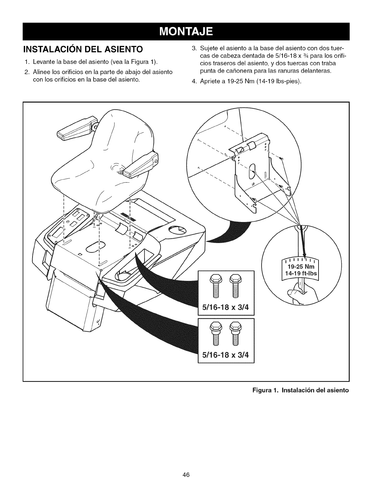
INSTALACION DEL ASIENTO
1. Levante la base del asiento (vea la Figura 1).
2. Alinee los orificios en la parte de abajo del asiento
con los orificios en la base del asiento.
3. Sujete el asiento a la base del asiento con dos tuer-
cas de cabeza dentada de 5/16-18 x 3_para los orifi-
cios traseros del asiento, y dos tuercas con traba
punta de caSonera para las ranuras delanteras.
4. Apriete a 19-25 Nm (14-19 Ibs-pies).
5/16-18 x 3/4
19-25 Nrn
14-19 ft-lbs
5/16-18 x 3/4
Figura 1. Instalaci6n del asiento
46
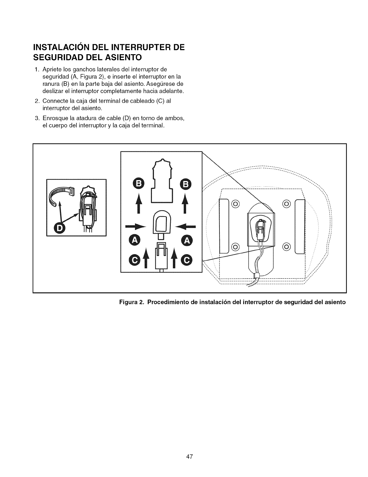
INSTALACION DEL INTERRUPTER DE
SEGURIDAD DEL ASIENTO
1. Apriete los ganchos laterales del interruptor de
seguridad (A, Figura 2), e inserte el interruptor en la
ranura (B) en la parte baja del asiento. Asegt3rese de
deslizar el interruptor completamente hacia adelante.
2. Connecte la caja del terminal de cableado (C) al
interruptor del asiento.
3. Enrosque la atadura de cable (D) en torno de ambos,
el cuerpo del interruptor y la caja del terminal.
t
@
@
\\
\\
//
//
/"
Figura 2. Procedimiento de instalaci6n del interruptor de seguridad del asiento
47
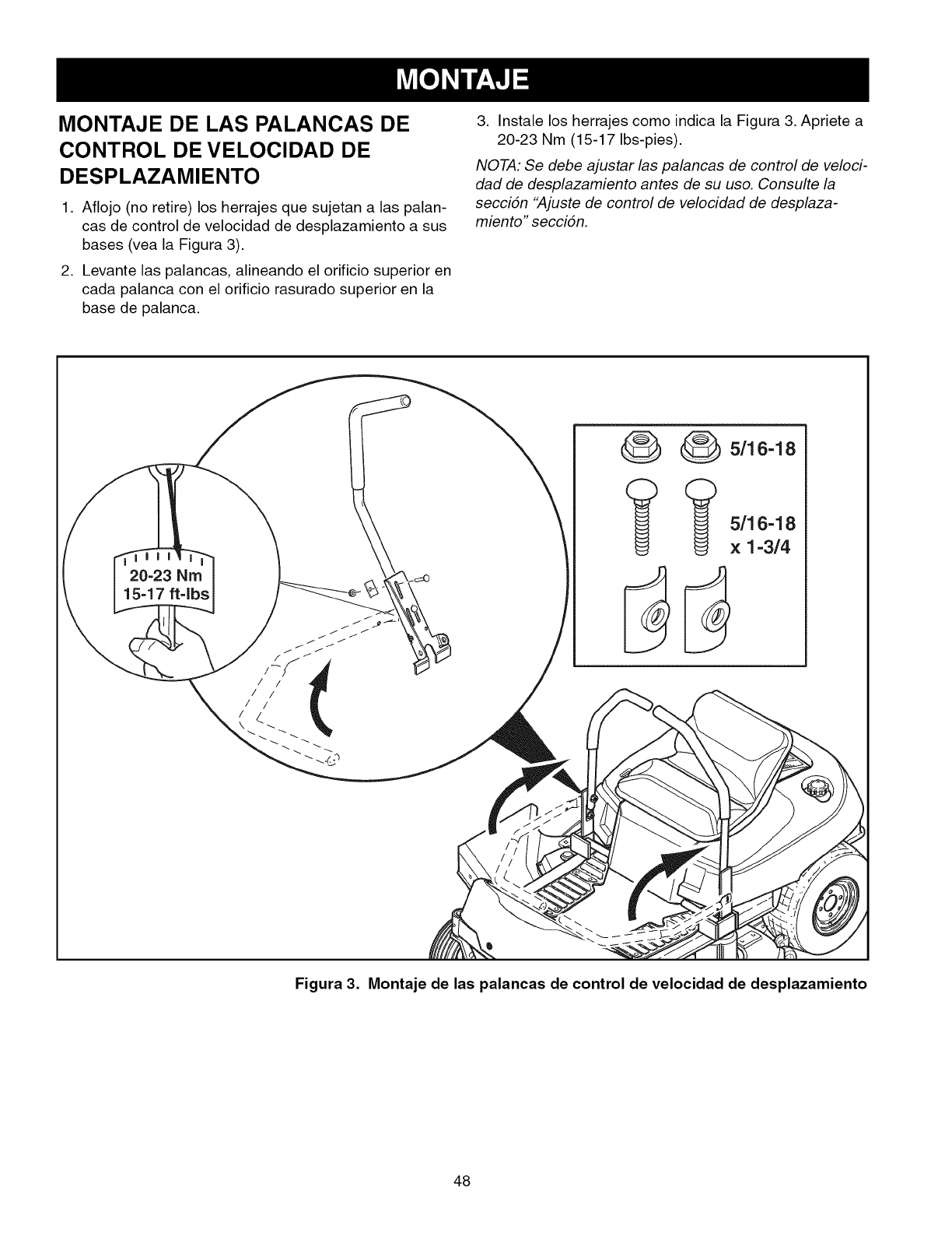
MONTAJE DE LAS PALANCAS DE
CONTROL DE VELOCIDAD DE
DESPLAZAMIENTO
1. Aflojo (no retire) los herrajes que sujetan a las palan-
cas de control de velocidad de desplazamiento a sus
bases (vea la Figura 3).
2. Levante las palancas, alineando el orificio superior en
cada palanca con el orificio rasurado superior en la
base de palanca.
3. Instale los herrajes como indica la Figura 3. Apriete a
20-23 Nm (15-17 Ibs-pies).
NOTA: Se debe ajustar las palancas de control de veloci-
dad de desplazamiento antes de su uso. Consulte la
seccidn "Ajuste de control de velocidad de desplaza-
miento" seccidn.
20-23 Nm
15-17 ft-lbs
_ 5/16-18
(_ (_) 5/16-18
x 1-3/4
Figura 3. Montaje de las palancas de control de velocidad de desplazamiento
48
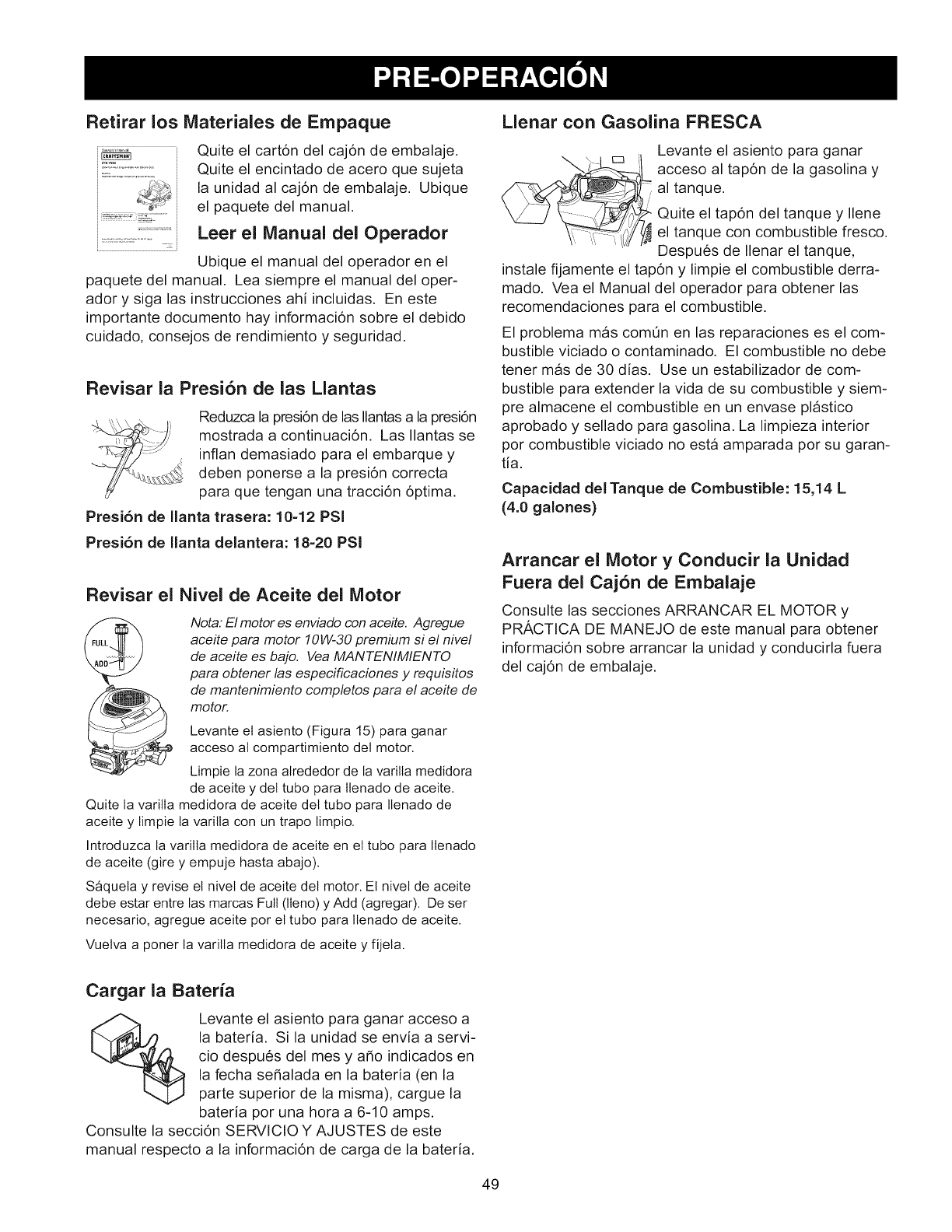
Retirar los Materiales de Empaque
........................: i
Quite el cart6n del caj6n de embalaje.
Quite el encintado de acero que sujeta
la unidad al caj6n de embalaje. Ubique
el paquete del manual.
Leer el Manual del Operador
Ubique el manual del operador en el
paquete del manual. Lea siempre el manual del oper-
ador y siga las instrucciones ahi incluidas. En este
importante documento hay informaci6n sobre el debido
cuidado, consejos de rendimiento y seguridad.
Revisar la Presi6n de las Mantas
Reduzca la presi6n de las Ilantasa la presi6n
mostrada a continuaci6n. Las Ilantas se
inflan demasiado para el embarque y
deben ponerse a la presi6n correcta
para que tengan una tracci6n 6ptima.
Presi6n de Ilanta trasera: 10-12 PSi
Presi6n de Ilanta delantera: 18=20 PSi
Revisar el Nivel de Aceite del Motor
Nora: El motor es enviado con aceite. Agregue
aceite para motor 10W-30 premium si el nivel
de aceite es bajo. Vea MANTENIMIENTO
para obtener las especificaciones y requisitos
de mantenimiento completos para el aceite de
motor.
Levante el asiento (Figura 15) para ganar
acceso al compartimiento del motor.
Limpie ta zona alrededor de la varilla medidora
de aceite y del tubo para ttenado de aceite.
Quite la varitla medidora de aceite del tubo para Ilenado de
aceite y limpie la varilla con un trapo limpio.
Introduzca la varilla medidora de aceite en el tubo para Itenado
de aceite (gire y empuje hasta abajo).
S_quela y revise el nivel de aceite del motor. El nivel de aceite
debe estar entre las marcas Full (lleno) y Add (agregar). De ser
necesario, agregue aceite por el tubo para Ilenado de aceite.
Vuelva a poner la varilla medidora de aceite y fijela.
Llenar con Gasolina FRESCA
Levante el asiento para ganar
,! acceso al tap6n de la gasolina y
al tanque.
Quite el tapdn del tanque y Ilene
el tanque con combustible fresco.
Despu6s de Ilenar el tanque,
instale fijamente el tap6n y limpie el combustible derra-
mado. Vea el Manual del operador para obtener las
recomendaciones para el combustible.
El problema mas comOn en las reparaciones es el com-
bustible viciado o contaminado. El combustible no debe
tenet mas de 30 dias. Use un estabilizador de com-
bustible para extender la vida de su combustible y siem-
pre almacene el combustible en un envase plastico
aprobado y sellado para gasolina. La limpieza interior
pot combustible viciado no esta amparada pot su garam
tia.
Capacidad del Tanque de Combustible: 15,14 L
(4.0 galones)
Arrancar el Motor y ¢onducir la Unidad
Fuera del Caj6n de Embalaje
Consulte las secciones ARRANCAR EL MOTOR y
PRACTICA DE MANEJO de este manual para obtener
informaci6n sobre arrancar la unidad y conducirla fuera
del caj6n de embalaje.
Cargar la Bateria
Levante el asiento para ganar acceso a
la bateria. Si la unidad se envia a servi-
cio despu6s del mes y a_o indicados en
la fecha se_alada en la bateria (en la
parte superior de la misma), cargue la
bateria pot una hora a 6-10 amps.
Consulte la secci6n SERVlCIO Y AJUSTES de este
manual respecto a la informaci6n de carga de la bateria.
49
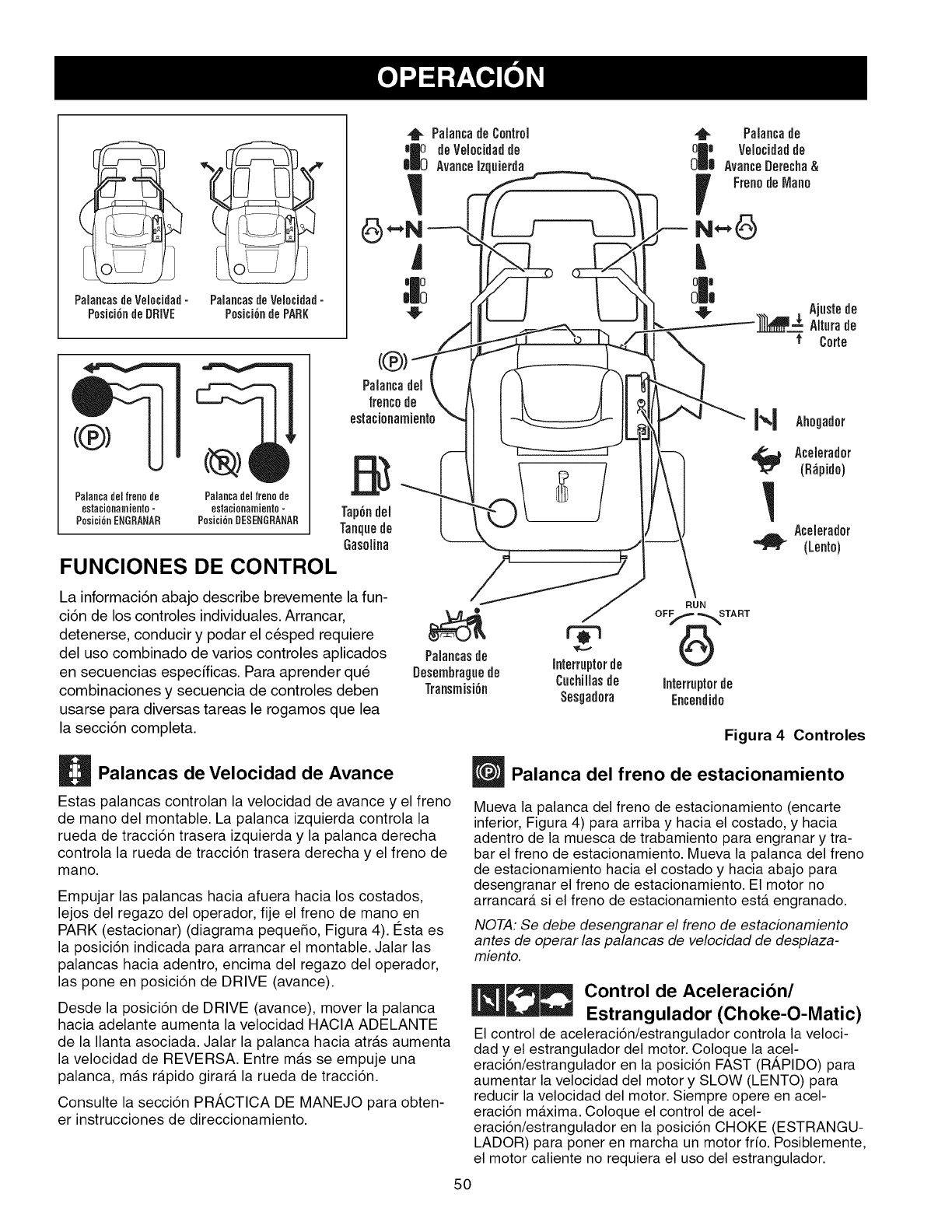
PalancadeControl
deVelo id dde
PalancasdeVelocidad- PalancasdeVelocidad- _A I I t
P0_ici6.deDRIVE P0eici6.dePARK ,I- JJ_
-- Gasolina "_
FU.C,O. SCO.T.O.
La informaci6n abajo describe brevemente la fun- /_
ci6n de los controles individuales. Arrancar, __ /"
detenerse, conducir y podar el cesped requiere _'0 _
del use combinado de varies controles aplicados Palancastie
en secuencias especfficas. Para aprender que Desembraguede Interrupterde
Cuchillasde
combinaciones y secuencia de controles deben Transmisi6n Sesgadora
usarse para diversas tareas le rogamos que lea
la secci6n completa.
RUN
OFf.START
Figura 4 Controles
Palancas de Velocidad de Avance
Estas palancas controlan la velocidad de avance y el freno
de mano del montable. La palanca izquierda controla la
rueda de tracci6n trasera izquierda y la palanca derecha
controla la rueda de tracci6n trasera derecha y el freno de
mano.
Empujar las palancas hacia afuera hacia los costados,
lejos del regazo del operador, fije el freno de mano en
PARK (estacionar) (diagrama pequeSo, Figura 4). 12staes
la posici6n indicada para arrancar el montable. Jalar las
palancas hacia adentro, encima del regazo del operador,
las pone en posici6n de DRIVE (avance).
Desde la posici6n de DRIVE (avance), mover la palanca
hacia adelante aumenta la velocidad HACIA ADELANTE
de la Ilanta asociada. Jalar la palanca hacia atras aumenta
la velocidad de REVERSA. Entre m_.s se empuje una
palanca, m_.s r_.pido girara la rueda de tracci6n.
Consulte la secci6n PR,_,CTICA DE MANEJO para obten-
er instrucciones de direccionamiento.
Palanca del freno de estacionamiento
Mueva la palanca del freno de estacionamiento (encarte
inferior, Figura 4) para arriba y hacia el costado, y hacia
adentro de la muesca de trabamiento para engranar y tra-
bar el freno de estacionamiento. Mueva la palanca del freno
de estacionamiento hacia el costado y hacia abajo para
desengranar el freno de estacionamiento. El motor no
arrancar_t si el freno de estacionamiento ester engranado.
NOTA: Se debe desengranar el freno de estacionamiento
antes de operar las palancas de velocidad de desplaza-
miento.
_]__ Control de Aceleracibn/
Estrangulador (Choke-O-Matic)
El control de aceleraci6n/estrangulador controla la veloci-
dad y el estrangulador del motor. Coloque la acel-
eraci6n/estrangulador en la posici6n FAST (Rh,PIDO) para
aumentar la velocidad del motor y SLOW (LENTO) para
reducir la velocidad del motor. Siempre opere en acel-
eraci6n maxima. Coloque el control de acel-
eraci6n/estrangulador en la posici6n CHOKE (ESTRANGU-
LADOR) para poner en marcha un motor frio. Posiblemente,
el motor caliente no requiera el uso del estrangulador.
50
Ajuste de Altura de Corte de la
Sesgadora
Para aumentar la altura de corte de la sesgadora (elevar
la cubierta de la sesgadora), oprima la parte superior del
ajuste de altura de corte amarillo de la sesgadora. Para
disminuir la altura de corte de la sesgadora (bajar la
cubierta de la sesgadora), optima la parte inferior del
ajuste. El tango de la altura de corte de la sesgadora es
9,5 a 3,8 cm (3-3/4" a 1-1/2"). El indicador de altura de
corte indica la posici6n de la cubierta de la sesgadora. El
indicador de altura de corte se encuentra en la parte
frontal del montable, justo detrAs de la pierna izquierda
del conductor.
Interruptor de Encendido
El interruptor de encendido arranca y detiene el motor;
tiene tres posiciones:
OFF (apagado) - Detiene el motor y corta el sistema
electrico.
RUN (activo) - Permite que el motor corra y suministra
energia al sistema electrico.
START (arrancar) - Mueve el motor para que arranque.
NOTA: Nunca deje el interruptor de encendido en la posi-
ciSn de RUN con el motor detenido. Esto drena la
baterfa.
_nterruptor de Cuchillas de la
Sesgadora
El interruptor de cuchillas de la sesgadora amarillo acti-
va y desactiva las cuchillas de la sesgadora. Para activar
las cuchillas de la sesgadora, jale el interruptor hacia
arriba. Para desactivar las cuchillas de la sesgadora,
empuje el interruptor hacia abajo. Coloque siempre el
control de velocidad del motor en FAST (rApido) antes
de activar las cuchillas de la sesgadora, y mientras poda
el cesped.
Palancas de Desembrague de
Transmisibn
Las palancas de desembrague de la transmisi6n desac-
tivan las transmisiones para que la unidad pueda empu-
jarse manualmente. Vea EMPUJAR LA UNIDAD MAN-
UALMENTE respecto a la informaci6n operacional.
Tanque de Gasolina
Para quitar el tap6n, gire a la izquierda.
SEGURIDAD GENERAL DE OPERACION
Antes de la primera operaci6n:
• Asegt3rese de leer toda la informaci6n en las secciones
de Seguridad y Operaci6n antes de intentar operar el
tractor o la podadora.
• Familiarfcese con todos los controles y c6mo detener la
unidad.
• Conduzca en un Area abierta sin podar el cesped para
acostumbrarse a conducir la unidad.
ADVERTENCIA
Si usted no entiende c6mo funciona un control
especifico, o no ha leido con detenimiento la secci6n
de FUNCIONES DE CONTROL, hAgalo ahora.
NO intente operar el tractor sin antes
familiarizarse con la ubicaci6n y la funci6n de
TODOS los controles.
51
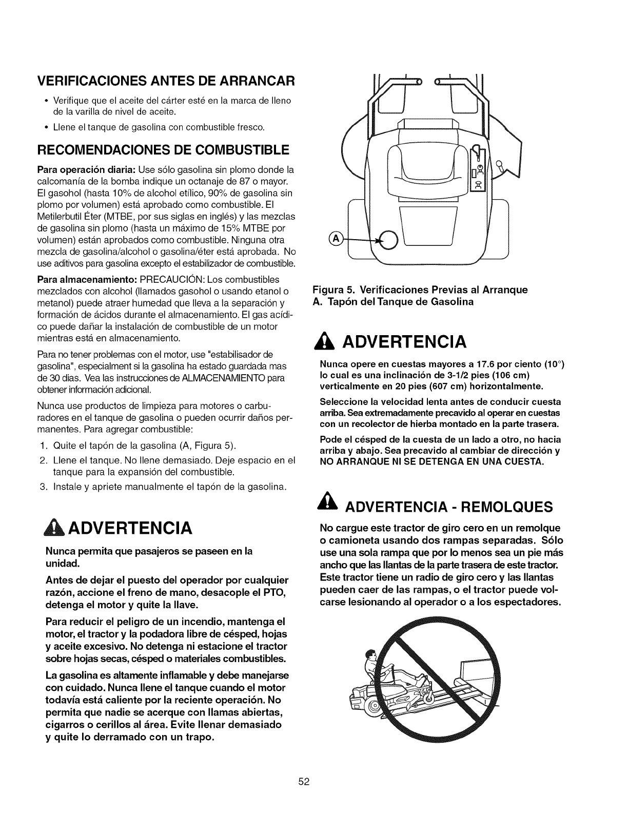
VERIFICACIONES ANTES DE ARRANCAR
• Verifique que el aceite del c_trter est_ en la marca de Ileno
de la varilla de nivel de aceite.
• Llene el tanque de gasolina con combustible fresco.
RECOMENDACIONES DE COMBUSTIBLE
Para operaci6n diaria: Use s61o gasolina sin plomo donde la
calcomanfa de la bomba indique un octanaje de 87 o mayor.
El gasohol (hasta 10% de alcohol etMco, 90% de gasolina sin
plomo por volumen) ester aprobado como combustible. El
Metilerbutil t_ter (MTBE, por sus siglas en ingles) y las mezclas
de gasolina sin plomo (hasta un maximo de 15% MTBE por
volumen) est_tn aprobados como combustible. Ninguna otra
mezcla de gasolina/alcohol o gasolina/eter ester aprobada. No
use aditivos para gasolina excepto el estabilizador de combustible.
Para almacenamiento: PRECAUCION: Los combustibles
mezclados con alcohol (llamados gasohol o usando etanol o
metanol) puede atraer humedad que Ileva a la separaci6n y
formaci6n de _tcidos durante el almacenamiento. El gas acidi-
co puede daSar la instalaci6n de combustible de un motor
mientras ester en almacenamiento.
Para no tener problemas con el motor, use "estabilisador de
gasolina", especialment si la gasolina ha estado guardada mas
de 30 dias. Vea las instrucciones de ALMACENAMIENTO para
obtener informacbn adicional.
Nunca use productos de limpieza para motores o carbu-
radores en el tanque de gasolina o pueden ocurrir daSos per-
manentes. Para agregar combustible:
1. Quite el tap6n de la gasolina (A, Figura 5).
2. Llene el tanque. No Ilene demasiado. Deje espacio en el
tanque para la expansi6n del combustible.
3. Instale y apriete manualmente el tap6n de la gasolina.
ADVERTENCIA
Nunca permita que pasajeros se paseen en la
unidad.
Antes de dejar el puesto del operador por cualquier
raz6n, accione el freno de mano, desacople el PTO,
detenga el motor y quite la Ilave.
Para reducir el peligro de un incendio, mantenga el
motor, el tractor y la podadora libre de c_sped, hojas
y aceite excesivo. No detenga ni estacione el tractor
sobre hojas secas, c_sped o materiales combustibles.
La gasolina es altamente inflamable y debe manejarse
con cuidado. Nunca Ilene el tanque cuando el motor
todavia est_ caliente por la reciente operaci6n. No
permita que nadie se acerque con llamas abiertas,
cigarros o cerillos al area. Evite Ilenar demasiado
y quite Io derramado con un trapo.
Figura 5. Verificaciones Previas al Arranque
A. Tap6n del Tanque de Gasolina
ADVERTENCIA
Nunca opere en cuestas mayores a 17.6 por ciento (10 °)
Io cual es una inclinacion de 3-1/2 pies (106 cm)
verticalmente en 20 pies (607 cm) horizontalmente.
Seleccione la velocidad lenta antes de conducir cuesta
arriba. Sea extremadamente precavido al operar en cuestas
con un recolector de hierba montado en la parte trasera.
Pode el c_sped de la cuesta de un lado a otro, no hacia
arriba yabajo. Sea precavido al cambiar de direccion y
NO ARRANQUE NI SE DETENGA EN UNA CUESTA.
ADVERTENCIA- REMOLQUES
No cargue este tractor de giro cero en un remolque
o camioneta usando dos rampas separadas. $61o
use una sola rampa que por Io menos sea un pie m_s
ancho que las Ilantasde la parte traserade este tractor.
Este tractor tiene un radio de giro cero y las Ilantas
pueden caer de las rampas, o el tractor puede vol-
carse lesionando al operador o a los espectadores.
52
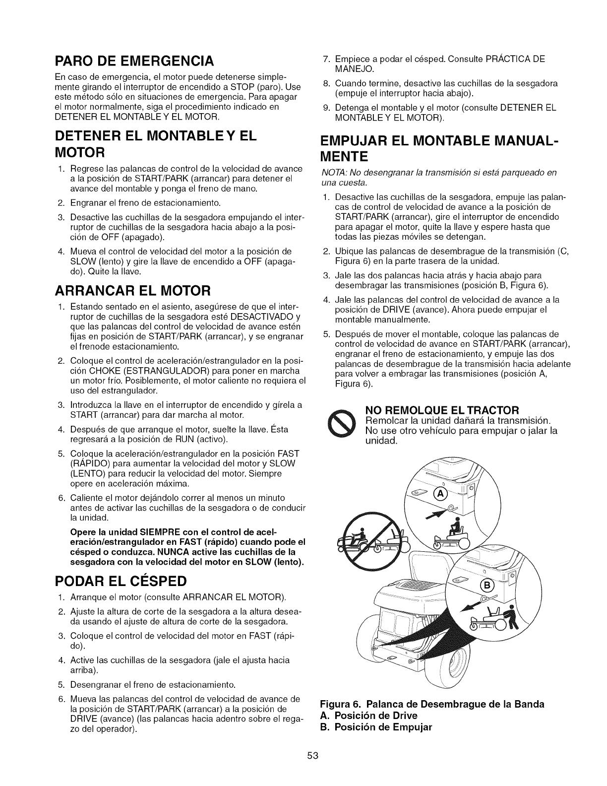
PARO DE EMERGENCIA
En caso de emergencia, el motor puede detenerse simple-
mente girando el interruptor de encendido a STOP (paro). Use
este m6todo s61o en situaciones de emergencia. Para apagar
el motor normalmente, siga el procedimiento indicado en
DETENER EL MONTABLE Y EL MOTOR.
DETENER EL MONTABLE Y EL
MOTOR
1,
2,
3.
4,
Regrese las palancas de control de la velocidad de avance
a la posici6n de START/PARK (arrancar) para detener el
avance del montable y ponga el freno de mano.
Engranar el freno de estacionamiento.
Desactive las cuchillas de la sesgadora empujando el inter-
ruptor de cuchillas de la sesgadora hacia abajo a la posi-
ci6n de OFF (apagado).
Mueva el control de velocidad del motor a la posici6n de
SLOW (lento) y gire la Ilave de encendido a OFF (apaga-
do). Quite la Ilave.
ARRANCAR EL MOTOR
1, Estando sentado en el asiento, asegQrese de que el inter-
ruptor de cuchillas de la sesgadora est6 DESACTIVADO y
que las palancas del control de velocidad de avance est6n
fijas en posici6n de START/PARK (arrancar), y se engranar
el frenode estacionamiento.
2, Coloque el control de aceleraci6n/estrangulador en la posi-
ci6n CHOKE (ESTRANGULADOR) para poner en marcha
un motor frio. Posiblemente, el motor caliente no requiera el
uso del estrangulador.
3. Introduzca la Ilave en el interruptor de encendido y girela a
START (arrancar) para dar marcha al motor.
4. Despu6s de que arranque el motor, suelte la Ilave. 12sta
regresara a la posici6n de RUN (activo).
5.
6,
Co[oque la aceleraci6n/estrangulador en la posici6n FAST
(RAPIDO) para aumentar la velocidad del motor y SLOW
(LENTO) para reducir la velocidad del motor. Siempre
opere en aceleraci6n maxima.
Caliente el motor dejandolo correr al menos un minuto
antes de activar las cuchillas de la sesgadora o de conducir
la unidad.
Opere la unidad SIEMPRE con el control de acel-
eracion/estrangulador en FAST (rapido) cuando pode el
c_sped o conduzca. NUNCA active las cuchillas de la
sesgadora con la velocidad del motor en SLOW (lento).
PODAR EL C¢:SPED
1. Arranque el motor (consulte ARRANCAR EL MOTOR).
2. Ajuste la altura de corte de la sesgadora a la altura desea-
da usando el ajuste de altura de corte de la sesgadora.
3. Coloque el control de velocidad del motor en FAST (rapi-
do).
4. Active las cuchillas de la sesgadora (jale el ajusta hacia
arriba).
5. Desengranar el freno de estacionamiento.
6, Mueva las palancas del control de velocidad de avance de
la posici6n de START/PARK (arrancar) a la posici6n de
DRIVE (avance) (las palancas hacia adentro sobre el rega-
zo del operador).
7,
8.
9.
Empiece a podar el c6sped. Consulte PRP,CTICA DE
MANEJO.
Cuando termine, desactive las cuchillas de la sesgadora
(empuje el interruptor hacia abajo).
Detenga el montable y el motor (consulte DETENER EL
MONTABLE Y EL MOTOR).
EMPUJAR EL MONTABLE MANUAL-
MENTE
NOTA: No desengranar la transmisidn si esta parqueado en
una cuesta.
1,
2,
3.
4.
Desactive las cuchillas de la sesgadora, empuje las palan-
cas de control de velocidad de avance a la posici6n de
START/PARK (arrancar), gire el interruptor de encendido
para apagar el motor, quite la Ilave y espere hasta que
todas las piezas m6viles se detengan.
Ubique las palancas de desembrague de la transmisi6n (C,
Figura 6) en la parte trasera de la unidad.
Jale las dos palancas hacia atras y hacia abajo para
desembragar las transmisiones (posici6n B, Figura 6).
Jale las palancas del control de velocidad de avance a la
posici6n de DRIVE (avance). Ahora puede empujar el
montable manualmente.
5, Despu6s de mover el montable, coloque las palancas de
control de velocidad de avance en START/PARK (arrancar),
engranar el freno de estacionamiento, y empuje las dos
palancas de desembrague de la transmisi6n hacia adelante
para volver a embragar las transmisiones (posici6n A,
Figura 6).
®NO REMOLQUE EL TRACTOR
Remolcar la unidad daSar& la transmisi6n.
No use otro vehiculo para empujar o jalar la
unidad.
Figura 6. Palanca de Desembrague de la Banda
A. Posici6n de Drive
B. Posici6n de Empujar
53
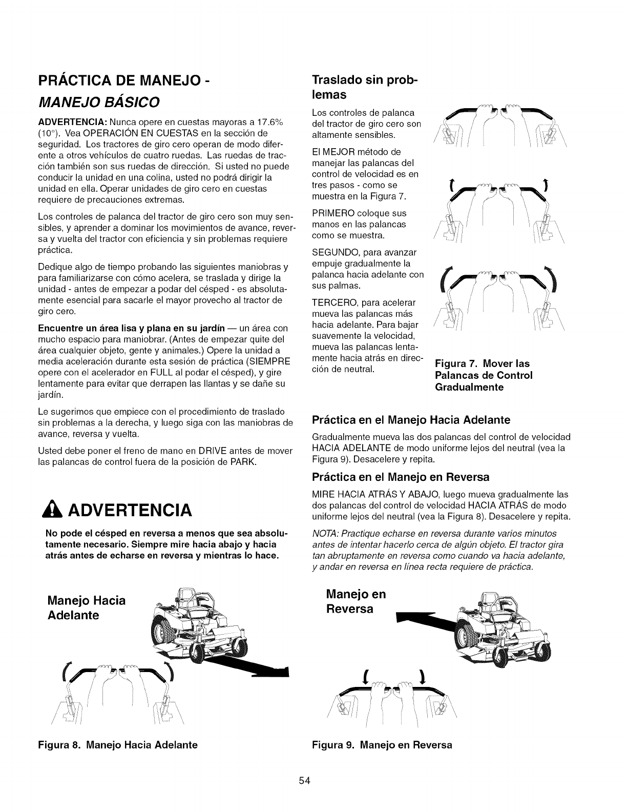
PRACTICA DE MANEJO -
MANEJO BASICO
ADVERTENCIA: Nunca opere en cuestas mayoras a 17.6%
(10°). Vea OPERACION EN CUESTAS en la secci6n de
seguridad. Los tractores de giro cero operan de modo difer-
ente a otros vehiculos de cuatro ruedas. Las ruedas de trac-
ci6n tambi_n son sus ruedas de direcci6n. Si usted no puede
conducir la unidad en una colina, usted no podra dirigir la
unidad en ella. Operar unidades de giro cero en cuestas
requiere de precauciones extremas.
Los controles de palanca del tractor de giro cero son muy sen-
sibles, y aprender a dominar los movimientos de avance, rever-
say vuelta del tractor con eficiencia y sin problemas requiere
practica.
Dedique algo de tiempo probando las siguientes maniobras y
para familiarizarse con c6mo acelera, se traslada y dirige la
unidad - antes de empezar a podar del c_sped - es absoluta-
mente esencial para sacarle el mayor provecho al tractor de
giro cero.
Encuentre un area lisa y plana en su jardin J un Area con
mucho espacio para maniobrar. (Antes de empezar quite del
Area cualquier objeto, gente y animales.) Opere la unidad a
media aceleraci6n durante esta sesi6n de practica (SIEMPRE
opere con el acelerador en FULL al podar el c_sped), y gire
lentamente para evitar que derrapen las Ilantas y se daSe su
jardin.
Le sugerimos que empiece con el procedimiento de traslado
sin problemas a la derecha, y luego siga con las maniobras de
avance, reversa y vuelta.
Usted debe poner el freno de mano en DRIVE antes de mover
las palancas de control fuera de la posici6n de PARK.
, ADVERTENCIA
No pode el c_sped en reversa a menos que sea absolu-
tamente necesario. Siempre mire hacia abajo y hacia
atras antes de echarse en reversa y mientras Io hace.
Manejo Hacia
Adelante
Traslado sin prob-
lemas
Los controles de palanca
del tractor de giro cero son
altamente sensibles.
El MEJOR m_todo de
manejar las )alancas del
control de velocidad es en
tres pasos - como se
muestra en la Figura 7.
PRIMERO coloque sus
manos en las palancas
como se muestra.
SEGUNDO, para avanzar
empuje gradualmente la
palanca hacia adelante con
sus palmas.
TERCERO, para acelerar
mueva las palancas mas
hacia adelante. Para bajar
suavemente la velocidad,
mueva las palancas lenta-
mente hacia atras en direc-
ci6n de neutral.
//
/
Figura 7. Mover las
Palancas de Control
Gradualmente
Practica en el Manejo Hacia Adelante
Gradualmente mueva las dos palancas del control de velocidad
HACIA ADELANTE de modo uniforme lejos del neutral (vea la
Figura 9). Desacelere y repita.
Practica en el Manejo en Reversa
MIRE HACIA ATRAS Y ABAJO, luego mueva gradualmente las
dos palancas del control de velocidad HACIA ATRAS de modo
uniforme lejos del neutral (vea la Figura 8). Desacelere y repita.
NOTA: Practique echarse en reversa durante varios minutos
antes de intentar hacerlo cerca de alg#n objeto. El tractor gira
tan abruptamente en reversa como cuando va hacia adelante,
y andar en reversa en Ifnea recta requiere de practica.
Manejo en
Reversa
Figura 8. Manejo Hacia Adelante Figura 9. Manejo en Reversa
54
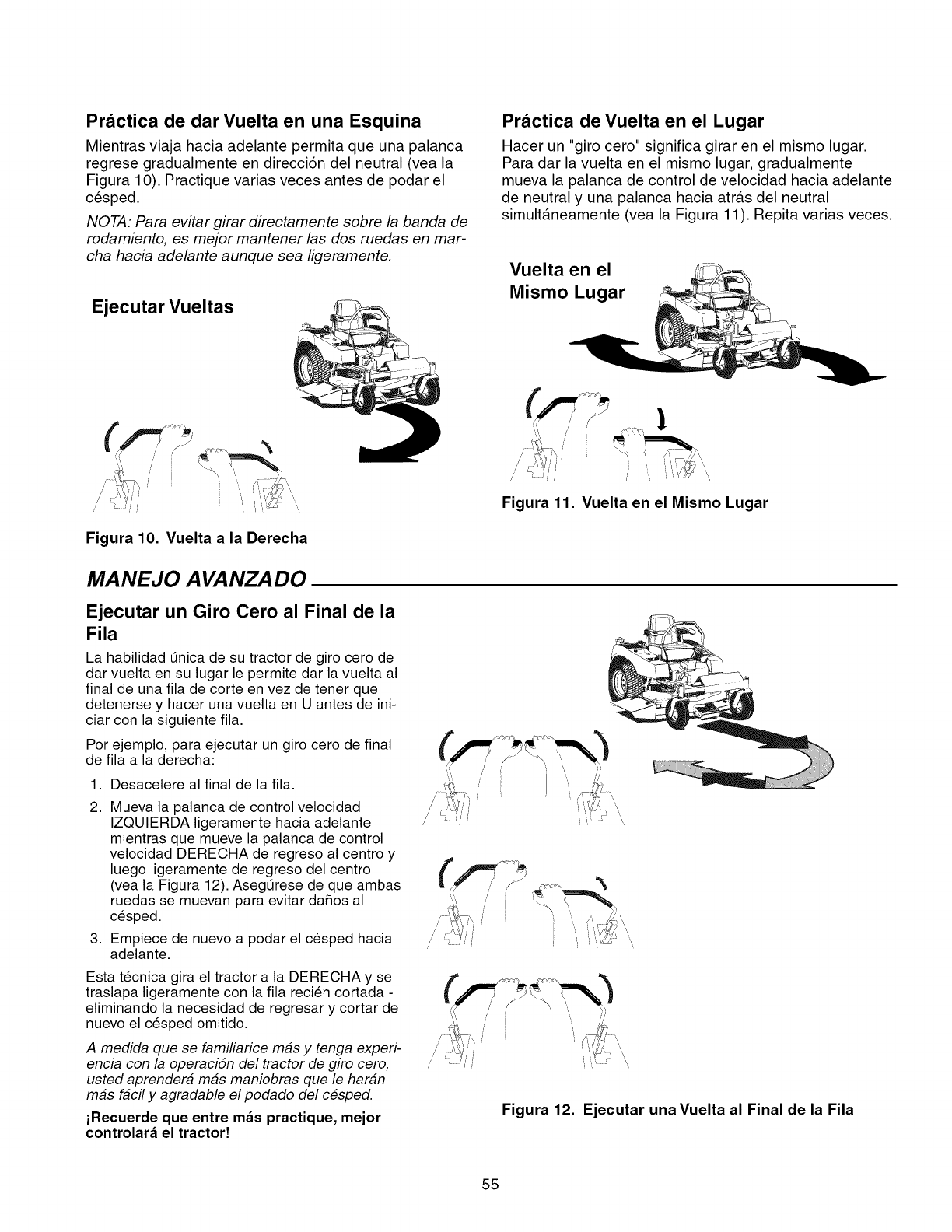
Practica de dar Vuelta en una Esquina
Mientras viaja hacia adelante permita que una palanca
regrese gradualmente en direcci6n del neutral (vea la
Figura 10). Practique varias veces antes de podar el
cesped.
NOTA: Para evitar girar directamente sobre la banda de
rodamiento, es mejor mantener las dos ruedas en mar-
cha hacia adelante aunque sea ligeramente.
Ejecutar Vueltas
Practica de Vuelta en el Lugar
Hacer un "giro cero" significa girar en el mismo lugar.
Para dar la vuelta en el mismo lugar, gradualmente
mueva la palanca de control de velocidad hacia adelante
de neutral y una palanca hacia atr&s del neutral
simultaneamente (vea la Figura 11). Repita varias veces.
Vuelta en el
Mismo Lugar
//
,/
//
Figura 10. Vuelta a la Derecha
MANEJO A VANZADO
Ejecutar un Giro Cero al Final de la
Fila
La habilidad 0nica de su tractor de giro cero de
dar vuelta en su lugar le permite dar la vuelta al
final de una fila de corte en vez de tener que
detenerse y hacer una vuelta en U antes de ini-
ciar con la siguiente fila.
Por ejemplo, para ejecutar un giro cero de final
de fila a la derecha:
1. Desacelere al final de la fila.
2,
3,
Mueva la palanca de control velocidad
IZQUIERDA ligeramente hacia adelante
mientras que mueve la palanca de control
velocidad DERECHA de regreso al centro y
luego ligeramente de regreso del centro
(vea la Figura 12). Aseg0rese de que ambas
ruedas se muevan para evitar daSos al
cesped.
Empiece de nuevo a podar el cesped hacia
adelante.
Esta tecnica gira el tractor a la DERECHA y se
traslapa ligeramente con la fila recien cortada -
eliminando la necesidad de regresar y cortar de
nuevo el cesped omitido.
A medida que se familiarice mas y tenga experi-
encia con la operacidn del tractor de giro cero,
usted aprender# mas maniobras que le hardn
mas fdcil y agradable el podado del cesped.
iRecuerde que entre m_s practique, mejor
controlar_ el tractor!
Figura 11. Vuelta en el Mismo Lugar
Figura 12. Ejecutar unaVuelta al Final de la Fila
55
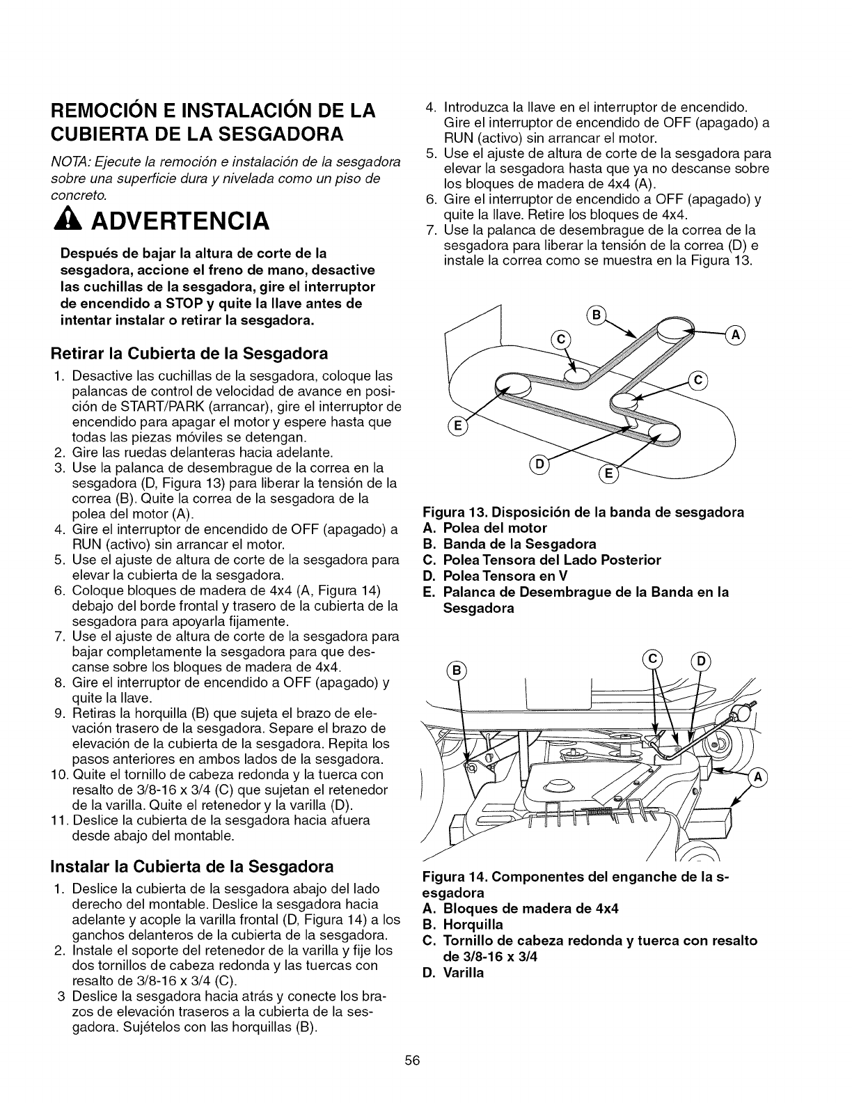
REMOCION E INSTALACION DE LA
CUBIERTA DE LA SESGADORA
NOTA: Ejecute la remocidn e instalacidn de la sesgadora
sobre una superficie dura y nivelada como un piso de
concreto,
ADVERTENCIA
Despuds de bajar la altura de corte de la
sesgadora, accione el freno de mano, desactive
las cuchillas de la sesgadora, gire el interruptor
de encendido a STOP y quite la Ilave antes de
intentar instalar o retirar la sesgadora.
Retirar la Cubierta de la Sesgadora
1. Desactive las cuchillas de la sesgadora, coloque las
palancas de control de velocidad de avance en posi-
ci6n de START/PARK (arrancar), gire el interruptor de
encendido para apagar el motor y espere hasta que
todas las piezas m6viles se detengan.
2. Gire las ruedas delanteras hacia adelante.
3. Use la palanca de desembrague de la correa en la
sesgadora (D, Figura 13) para liberar la tensi6n de la
correa (B). Quite la correa de la sesgadora de la
polea del motor (A).
4. Gire el interruptor de encendido de OFF (apagado) a
RUN (activo) sin arrancar el motor.
5. Use el ajuste de altura de corte de la sesgadora para
elevar la cubierta de la sesgadora.
6. Coloque bloques de madera de 4x4 (A, Figura 14)
debajo del borde frontal y trasero de la cubierta de la
sesgadora para apoyarla fijamente.
7. Use el ajuste de altura de corte de la sesgadora para
bajar completamente la sesgadora para que des-
canse sobre los bloques de madera de 4x4.
8. Gire el interruptor de encendido a OFF (apagado) y
quite la Ilave.
9. Retiras la horquilla (B) que sujeta el brazo de ele-
vaci6n trasero de la sesgadora. Separe el brazo de
elevaci6n de la cubierta de la sesgadora. Repita los
pasos anteriores en ambos lados de la sesgadora.
10. Quite el tornillo de cabeza redonda y la tuerca con
resalto de 3/8-16 x 3/4 (C) que sujetan el retenedor
de la varilla. Quite el retenedor y la varilla (D).
11. Deslice la cubierta de la sesgadora hacia afuera
desde abajo del montable.
Instalar la Cubierta de la Sesgadora
1. Deslice la cubierta de la sesgadora abajo del lado
derecho del montable. Deslice la sesgadora hacia
adelante y acople la varilla frontal (D, Figura 14) a los
ganchos delanteros de la cubierta de la sesgadora.
2. Instale el soporte del retenedor de la varilla y fije los
dos tornillos de cabeza redonda y las tuercas con
resalto de 3/8-16 x 3/4 (C).
3 Deslice la sesgadora hacia atr&s y conecte los bra-
zos de elevaci6n traseros a la cubierta de la ses-
gadora. Sujetelos con las horquillas (B).
4. Introduzca la Ilave en el interruptor de encendido.
Gire el interruptor de encendido de OFF (apagado) a
RUN (activo) sin arrancar el motor.
5. Use el ajuste de altura de corte de la sesgadora para
elevar la sesgadora hasta que ya no descanse sobre
los bloques de madera de 4x4 (A).
6. Gire el interruptor de encendido a OFF (apagado) y
quite la Ilave. Retire los bloques de 4x4.
7. Use la palanca de desembrague de la correa de la
sesgadora para liberar la tensi6n de la correa (D) e
instale la correa como se muestra en la Figura 13.
Figura 13. Disposici6n de la banda de sesgadora
A. Polea del motor
B. Banda de la Sesgadora
C. Polea Tensora del Lado Posterior
D. Polea Tensora en V
E. Palanca de Desembrague de la Banda en la
Sesgadora
J
7
Figura 14. Componentes del enganche de la s-
esgadora
A. Bloques de madera de 4x4
B. Horquilla
C. Tornillo de cabeza redonda y tuerca con resalto
de 3/8-16 x 314
D. Varilla
56
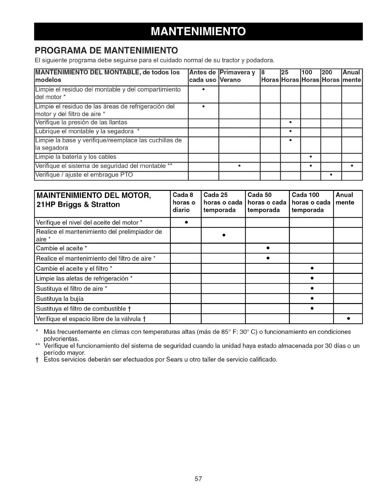
PROGRAMA DE MANTENIMIENTO
El siguiente programa debe seguirse para el cuidado normal de su tractor y podadora.
MANTENIMIENTO DEL MONTABLE, de toclos los Antes de Primavera y 8 25 100 200 Anual
moclelos eada uso Verano Horas Horas Horas Horas mente
Limpie el residuo del montable y del compartimiento ,,
del motor *
Limpie el residuo de las areas de refrigeraci6n del ,,
motor y del filtro de aire *
Verifique la presi6n de las Ilantas *
Lubrique el montable y la segadora * ,,
Limpie la base y verifique/reemplace las cuchillas de *
la segadora
Limpie la bateria y los cables *
Verifique el sistema de seguridad del montable ** * * *
Verifique /ajuste el embrague PTO ,,
MAINTENIMIENTO DEL MOTOR, Cada 8 Cada 25 Cada 50 Cada 100 Anual
21HP Briggs & Stratton horas o horas o cada horas o cada horas o cada mente
diario temporada temporada temporada
Verifique el nivel del aceite del motor * •
Realice el mantenimiento del prelimpiador de
aire *
Cambie el aceite * •
Realice el mantenimiento del filtro de aire * •
Cambie el aceite y el filtro * •
Limpie las aletas de refrigeraci6n * •
Sustituya el filtro de aire * •
Sustituya la bujia •
Sustituya el filtro de combustible 1 •
Verifique el espacio libre de la v_lvula 1 •
* M&s frecuentemente en climas con temperaturas altas (m&s de 85 ° F: 30° C) o funcionamiento en condiciones
polvorientas.
** Verifique el funcionamiento del sistema de seguridad cuando la unidad haya estado almacenada por 30 dias o un
peHodo mayor.
1- Estos servicios deber&n ser efectuados por Sears u otro taller de servicio calificado.
57
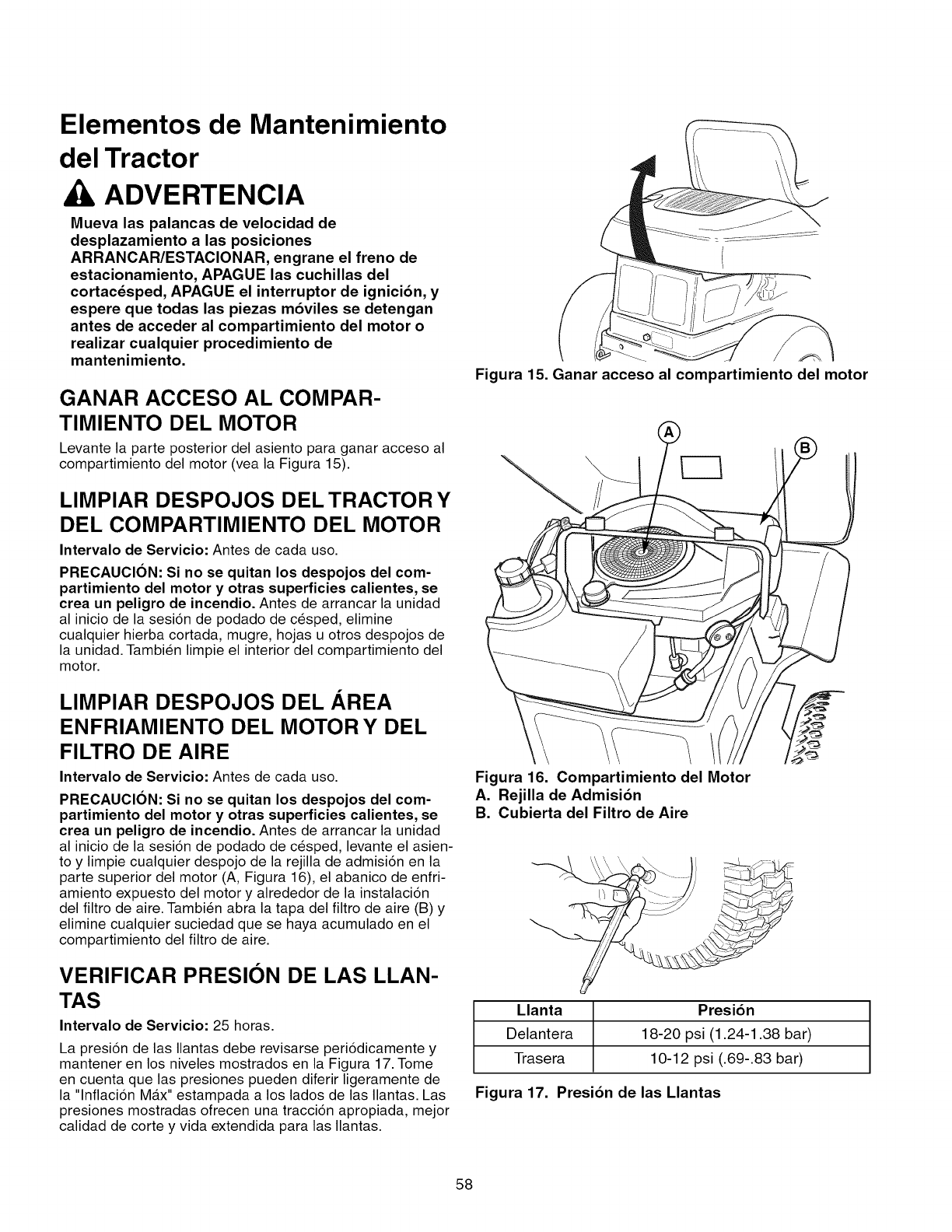
Elementos de Mantenimiento
del Tractor
AADVERTENCIA
Mueva las palancas de velocidad de
desplazamiento a las posiciones
ARRANCAR/ESTACIONAR, engrane el freno de
estacionamiento, APAGUE las cuchillas del
cortacdsped, APAGUE el interruptor de ignici6n, y
espere que todas las piezas m6viles se detengan
antes de acceder al compartimiento del motor o
realizar cualquier procedimiento de
mantenimiento.
GANAR ACCESO AL COMPAR-
TIMIENTO DEL MOTOR
Levante la parte posterior del asiento para ganar acceso al
compartimiento del motor (vea la Figura 15).
LIMPIAR DESPOJOS DEL TRACTOR Y
DEL COMPARTIMIENTO DEL MOTOR
Intervalo de Servicio: Antes de cada use.
PRECAUCION: Si no se quitan los despojos del com-
partimiento del motor y otras superficies calientes, se
crea un peligro de incendio. Antes de arrancar la unidad
al inicio de la sesi6n de podado de cesped, elimine
cualquier hierba cortada, mugre, hojas u otros despojos de
la unidad. Tambien limpie el interior del compartimiento del
motor.
LIMPIAR DESPOJOS DEL AREA
ENFRIAMIENTO DEL MOTOR Y DEL
FILTRO DE AIRE
Intervalo de Servicio: Antes de cada use.
PRECAUCION: Si no se quitan los despojos del com-
partimiento del motor y otras superficies calientes, se
crea un peligro de incendio. Antes de arrancar la unidad
al inicio de la sesi6n de podado de cesped, levante el asien-
to y limpie cualquier despojo de la rejilla de admisi6n en la
parte superior del motor (A, Figura 16), el abanico de enfri-
amiento expuesto del motor y alrededor de la instalaci6n
del filtro de aire. Tambien abra la tapa del filtro de aire (B) y
elimine cualquier suciedad que se haya acumulado en el
compartimiento del filtro de aire.
VERIFICAR PRESION DE LAS LLAN-
TAS
Intervalo de Servicio: 25 horas.
La presi6n de las Ilantas debe revisarse peri6dicamente y
mantener en los niveles mostrados en la Figura 17. Tome
en cuenta que las presiones pueden diferir ligeramente de
la "lnflaci6n MAx" estampada a los lados de las Ilantas. Las
presiones mostradas ofrecen una tracci6n apropiada, mejor
calidad de corte y vida extendida para las Ilantas.
Figura 15. Ganar acceso al compartimiento del motor
Figura 16. Compartimiento del Motor
A. Rejilla de Admisi6n
B. Cubierta del Filtro de Aire
Llanta Presi6n
Delantera 18-20 psi (1.24-1.38 bar)
Trasera 10-12 psi (.69-.83 bar)
Figura 17. Presi6n de las Mantas
58
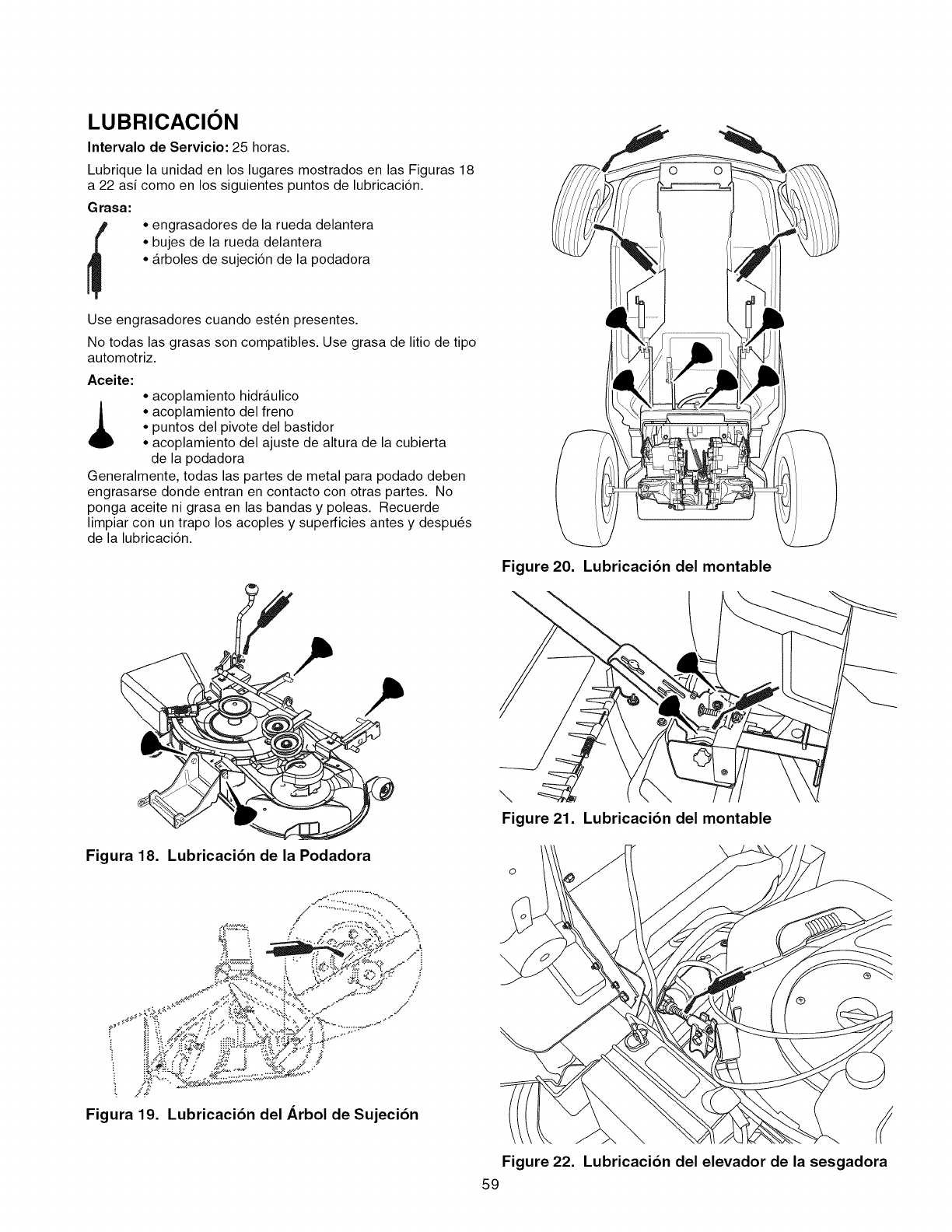
LUBRICACION
Intervalo de Servicio: 25 horas.
Lubrique la unidad en los lugares mostrados en las Figuras 18
a 22 asi como en los siguientes puntos de lubricaci6n.
Grasa:
•engrasadores de la rueda delantera
• bujes de la rueda delantera
• arboles de sujeci6n de la podadora
Use engrasadores cuando est6n presentes.
No todas las grasas son compatibles. Use grasa de litio de tipo
automotriz.
Aceite:
• acoplamiento hidraulico
• acoplamiento del freno
• puntos del pivote del bastidor
• acoplamiento del ajuste de altura de la cubierta
de la podadora
Generalmente, todas las partes de metal para podado deben
engrasarse donde entran en contacto con otras partes. No
ponga aceite ni grasa en las bandas y poleas. Recuerde
limpiar con un trapo los acoples y superficies antes y despu6s
de la lubricaci6n.
Figura 18. Lubricaci6n de la Podadora
/,,. ............:.:.::,. %.,
,_..-:'.:::?,-: _. '.. ", ..
=.e, ,..xj_ /" :
-_, r.-"_,...:t_,_,.
_:._,;:_ ./ ti__'_"" ......... J"
_,_t::.-_4_,_,_,.i\ _._:'c_C_?' ,:
.j,.-_ .,_,_,,.,*._..'-_2_,f_ ._..i:>" /
p_ uh
Figura 19. Lubricaci6n del Arbol de Sujeci6n
Figure 20.
\
\
Figure 21.
Lubricacibn del montable
Lubricacibn del montable
Figure 22. Lubricaci6n del elevador de la sesgadora
59
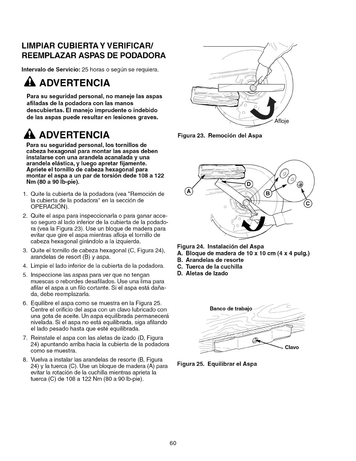
LIMPIAR CUBIERTA Y VERIFICAR/
REEMPLAZAR ASPAS DE PODADORA
Intervalo de Servicio: 25 horas o segQn se requiera.
ADVERTENCIA
Para su seguridad personal, no maneje las aspas
afiladas de la podadora con las manos
descubiertas. El manejo imprudente o indebido
de las aspas puede resultar en lesiones graves.
ADVERTENCIA
Para su seguridad personal, los tornillos de
cabeza hexagonal para montar las aspas deben
instalarse con una arandela acanalada y una
arandela el_stica, y luego apretar fijamente.
Apriete el tornillo de cabeza hexagonal para
montar el aspa a un par de torsi6n dede 108 a 122
Nm (80 a 90 Ib-pie).
1. Quite la cubierta de la podadora (vea "Remoci6n de
la cubierta de la podadora" en la secci6n de
OPERACION).
2. Quite el aspa para inspeccionarla o para ganar acce-
so seguro al lado inferior de la cubierta de la podado-
ra (vea la Figura 23). Use un bloque de madera para
evitar que gire el aspa mientras afloja el tornillo de
cabeza hexagonal girAndolo a la izquierda.
3. Quite el tornillo de cabeza hexagonal (C, Figura 24),
arandelas de resort (B) y aspa.
4. Limpie el lado inferior de la cubierta de la podadora.
5. Inspeccione las aspas para ver que no tengan
muescas o rebordes desafilados. Use una lima para
afilar el aspa a un filo cortante. Si el aspa esta daSa-
da, debe reemplazarla.
6. Equilibre el aspa como se muestra en la Figura 25.
Centre el orificio del aspa con un clavo lubricado con
una gota de aceite. Un aspa equilibrada permanecer_
nivelada. Si el aspa no est& equilibrada, siga afilando
el lado pesado hasta que est_ equilibrada.
7. Reinstale el aspa con las aletas de izado (D, Figura
24) apuntando arriba hacia la cubierta de la podadora
como se muestra.
8. Vuelva a instalar las arandelas de resorte (B, Figura
24) y la tuerca (C). Use un bloque de madera (A) para
evitar la rotaci6n de la cuchilla mientras aprieta la
tuerca (C) de 108 a 122 Nm (80 a 90 Ib-pie).
Figura 23. Remoci6n del Aspa
Afloje
\
Figura 24. Instalaci6n del Aspa
A. Bloque de madera de 10 x10 cm (4 x4pulg.)
B. Arandelas de resorte
C. Tuerca de la cuchilla
D. Aletas de Izado
Clavo
Figura 25. Equilibrar el Aspa
60
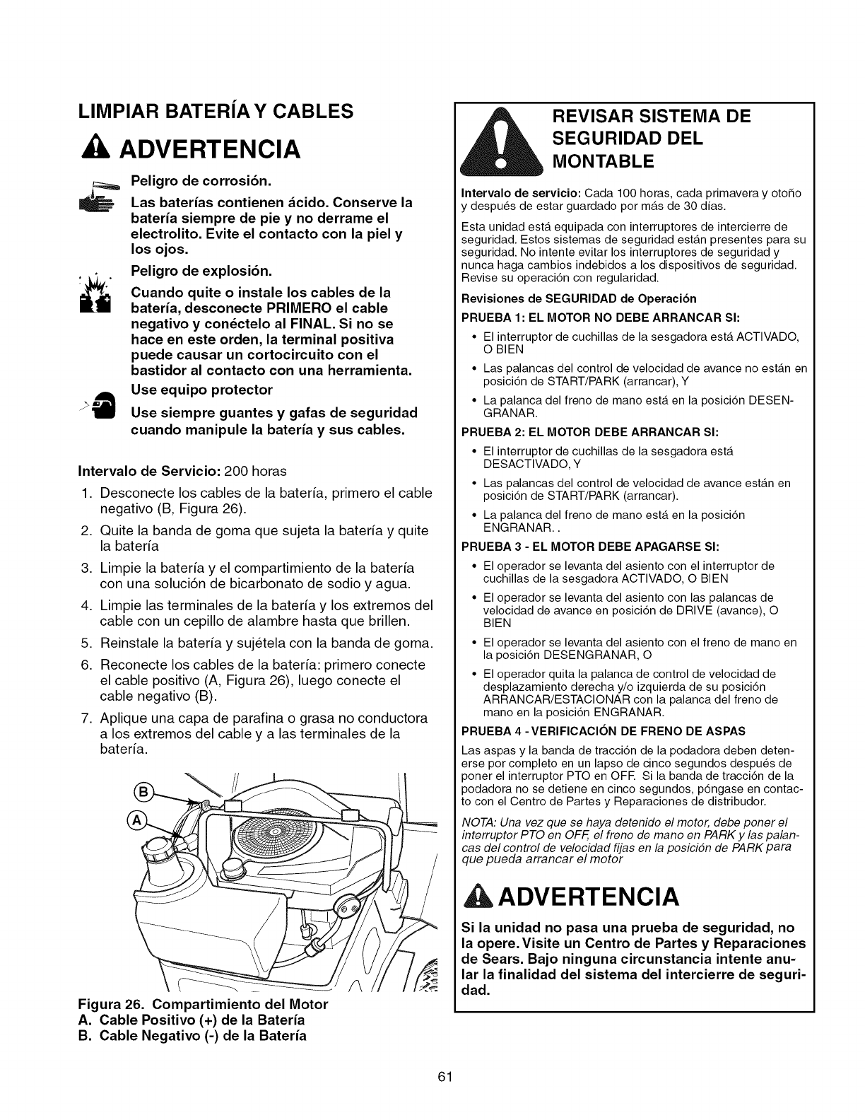
LIMPIAR BATERJA Y CABLES
, ADVERTENCIA
Peligro de corrosi6n.
Las baterias contienen dcido. Conserve la
bateria siempre de pie y no derrame el
electrolito. Evite el contacto con la piel y
losojos.
Peligro de explosi6n.
Cuando quite o instale los cables de la
bateria, desconecte PRIMERO el cable
negativo y condctelo al FINAL. Si no se
hace en este orden, la terminal positiva
puede causar un cortocircuito con el
bastidor al contacto con una herramienta.
Use equipo protector
Use siempre guantes y gafas de seguridad
cuando manipule la bateria y sus cables.
Intervalo de Servicio: 200 horas
,
2.
Desconecte los cables de la baterfa, primero el cable
negativo (B, Figura 26).
Quite la banda de goma que sujeta la baterfa y quite
la baterfa
,
4.
5.
6.
Limpie la bateria y el compartimiento de la baterfa
con una soluciSn de bicarbonato de sodio y agua.
Limpie las terminales de la baterfa y los extremos del
cable con un cepillo de alambre hasta que brillen.
Reinstale la baterfa y sujetela con la banda de goma.
Reconecte los cables de la baterfa: primero conecte
el cable positivo (A, Figura 26), luego conecte el
cable negativo (B).
7. Aplique una capa de parafina o grasa no conductora
a los extremos del cable y a las terminales de la
baterfa.
Figura 26. Compartimiento del Motor
A. Cable Positivo (+) de la Bateria
B. Cable Negativo (-) de la Bateria
REVISAR SISTEMA DE
SEGURIDAD DEL
MONTABLE
Intervalo de servicio: Cada 100 horas, cada primavera y otoSo
y despu_s de estar guardado por m_.s de 30 dfas.
Esta unidad est,. equipada con interruptores de intercierre de
seguridad. Estos sistemas de seguridad est_tn presentes para su
seguridad. No intente evitar los interruptores de seguridad y
nunca haga cambios indebidos a los dispositivos de seguridad.
Revise su operaciSn con regularidad.
Revisiones de SEGURIDAD de Operacibn
PRUEBA 1: EL MOTOR NO DEBE ARRANCAR SI:
•El interruptor de cuchillas de la sesgadora est,. ACTIVADO,
O BIEN
• Las palancas del control de velocidad de avance no est_.n en
posiciSn de START/PARK (arrancar), Y
• La palanca del freno de mano est,. en la posiciSn DESEN-
GRANAR.
PRUEBA 2: EL MOTOR DEBE ARRANCAR SI:
• El interruptor de cuchillas de la sesgadora est,.
DESACTIVADO, Y
• Las palancas del control de velocidad de avance est_.n en
posiciSn de START/PARK (arrancar).
• La palanca del freno de mano est,. en la posiciSn
ENGRANAR..
PRUEBA 3 - EL MOTOR DEBE APAGARSE SI:
El operador se levanta del asiento con el interruptor de
cuchillas de la sesgadora ACTIVADO, O BIEN
El operador se levanta del asiento con las palancas de
velocidad de avance en posiciSn de DRIVE (avance), O
BIEN
• El operador se levanta del asiento con el freno de mano en
la posiciSn DESENGRANAR, O
• El operador quita la palanca de control de velocidad de
desplazamiento derecha y/o izquierda de su posiciSn
ARRANCAR/ESTACIONAR con la palanca del freno de
mano en la posiciSn ENGRANAR.
PRUEBA 4 -VERIFIOAClON DE FRENO DE ASPAS
Las aspas y la banda de tracciSn de la podadora deben deten-
erse por completo en un lapso de cinco segundos despu_s de
poner el interruptor PTO en OFE Si la banda de tracciSn de la
podadora no se detiene en cinco segundos, pSngase en contac-
to con el Centro de Partes y Reparaciones de distribudor.
NOTA: Una vez que se haya detenido el motor, debe poner el
interruptor PTO en OFF, el freno de mano en PARK y las palan-
cas del control de velocidad fijas en la posici6n de PARK para
que pueda arrancar el motor
ADVERTENCIA
Si la unidad no pasa una prueba de seguridad, no
la opere. Visite un Centro de Partes y Reparaciones
de Sears. Bajo ninguna circunstancia intente anu-
lar la finalidad del sistema del intercierre de seguri-
dad.
61
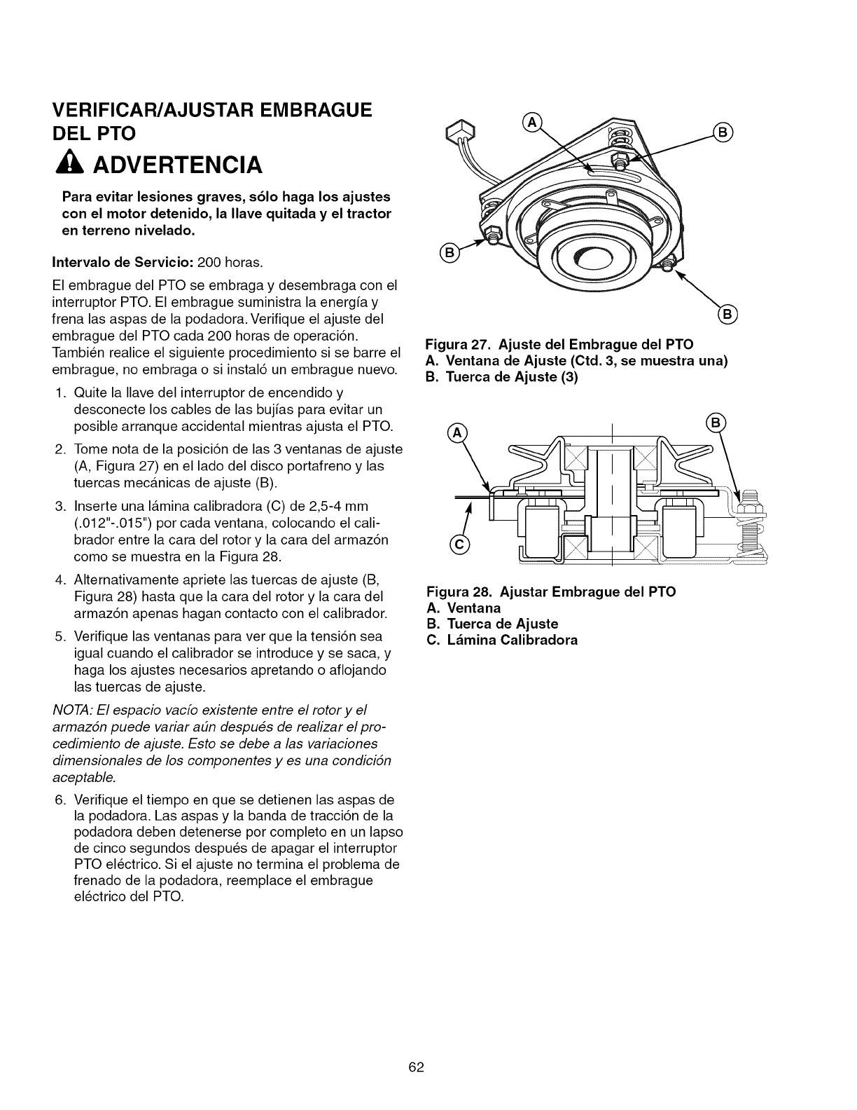
VERIFICAR/AJUSTAR EMBRAGUE
DEL PTO
ADVERTENCIA
Para evitar lesiones graves, s61o haga los ajustes
con el motor detenido, la Ilave quitada y el tractor
en terreno nivelado.
Intervalo de Servicio: 200 horas.
El embrague del PTO se embraga y desembraga con el
interruptor PTO. El embrague suministra la energ[a y
frena las aspas de la podadora. Verifique el ajuste del
embrague del PTO cada 200 horas de operaci6n.
Tambien realice el siguiente procedimiento si se barre el
embrague, no embraga o si instal6 un embrague nuevo.
1. Quite la Ilave del interruptor de encendido y
desconecte los cables de las buj[as para evitar un
posible arranque accidental mientras ajusta el PTO.
2. Tome nota de la posici6n de las 3 ventanas de ajuste
(A, Figura 27) en el lado del disco portafreno y las
tuercas mecAnicas de ajuste (B).
3. Inserte una lamina calibradora (C) de 2,5-4 mm
(.012"-.015") por cada ventana, colocando el cali-
brador entre la cara del rotor y la cara del armaz6n
como se muestra en la Figura 28.
4. Alternativamente apriete las tuercas de ajuste (B,
Figura 28) hasta que la cara del rotor y la cara del
armaz6n apenas hagan contacto con el calibrador.
5. Verifique las ventanas para vet que la tensi6n sea
igual cuando el calibrador se introduce y se saca, y
haga los ajustes necesarios apretando o aflojando
las tuercas de ajuste.
NOTA: El espacio vacfo existente entre el rotor y el
armaz6n puede variar a_n despu_s de realizar el pro-
cedimiento de ajuste. Esto se debe a las variaciones
dimensionales de los componentes yes una condici6n
aceptable.
6. Verifique el tiempo en que se detienen las aspas de
la podadora. Las aspas y la banda de tracci6n de la
podadora deben detenerse pot completo en un lapso
de cinco segundos despues de apagar el interruptor
PTO electrico. Si el ajuste no termina el problema de
frenado de la podadora, reemplace el embrague
electrico del PTO.
Figura 27. Ajuste del Embrague del PTO
A. Ventana de Ajuste (Ctd. 3, se muestra una)
B. Tuerca de Ajuste (3)
I
Figura 28. Ajustar Embrague del PTO
A. Ventana
B. Tuerca de Ajuste
C. LAmina Calibradora
62
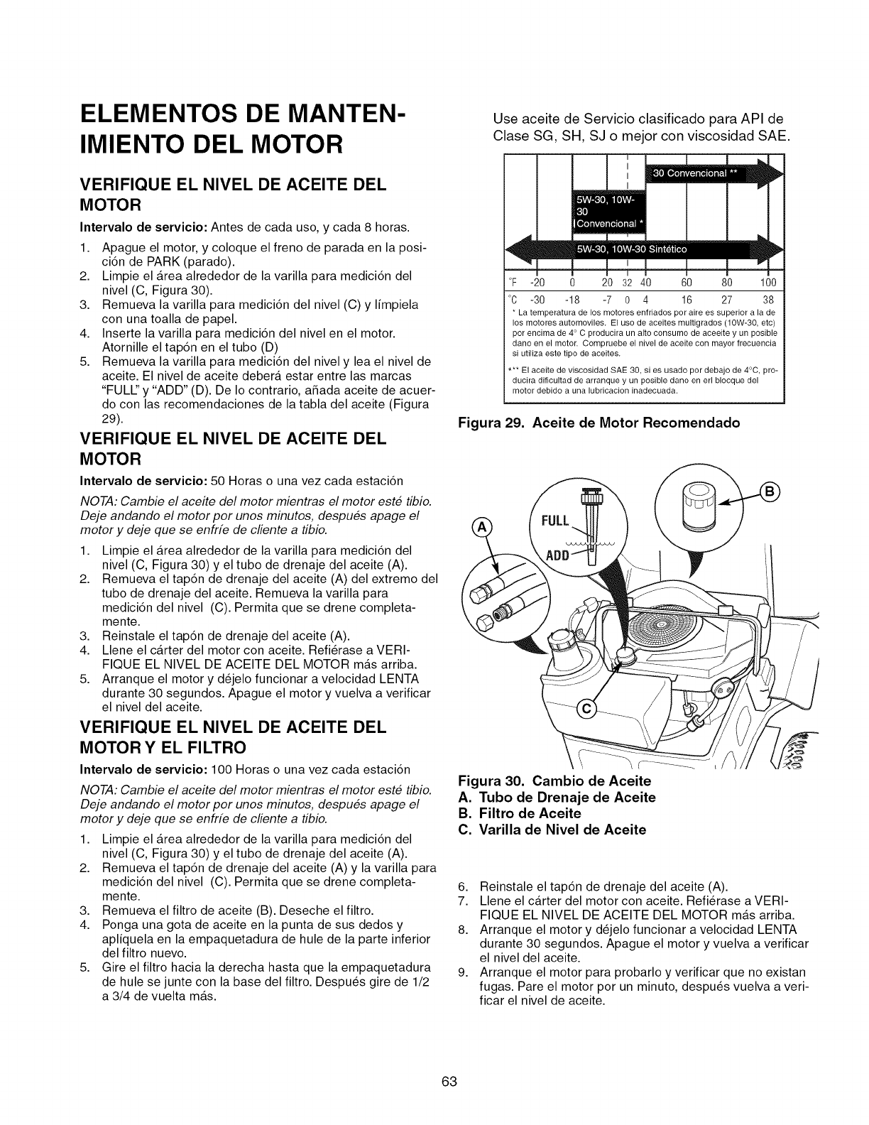
ELEMENTOS DE MANTEN-
IMIENTO DEL MOTOR
VERIFIQUE EL NIVEL DE ACEITE DEL
MOTOR
Intervalo de servicio: Antes de cada uso, y cada 8 horas.
1. Apague el motor, y coloque el freno de parada en la posi-
ci6n de PARK (parado).
2. Limpie el Area alrededor de la varilla para medici6n del
nivel (C, Figura 30).
3. Remueva la varilla para medici6n del nivel (C) y limpiela
con una toalla de papel.
4. Inserte la varilla para medici6n del nivel en el motor.
Atornille el tap6n en el tubo (D)
5. Remueva la varilla para medici6n del nivel y lea el nivel de
aceite. El nivel de aceite debera estar entre las marcas
"FULl" y "ADD" (D). De Io contrario, aSada aceite de acuer-
do con las recomendaciones de la tabla del aceite (Figura
29).
VERIFIQUE EL NIVEL DE ACEITE DEL
MOTOR
Intervalo de servicio: 50 Horas o una vez cada estaci6n
NOTA: Cambie el aceite del motor mientras el motor este tibio.
Deje andando el motor por unos minutos, despues apage el
motor y deje que se enfrfe de cliente a tibio.
1. Limpie el Area alrededor de la varilla para medici6n del
nivel (C, Figura 30) y el tubo de drenaje del aceite (A).
2. Remueva el tap6n de drenaje del aceite (A) del extremo del
tubo de drenaje del aceite. Remueva la varilla para
medici6n del nivel (C). Permita que se drene completa-
mente.
3. Reinstale el tap6n de drenaje del aceite (A).
4. Llene el carter del motor con aceite. Refi@ase a VERI-
FIQUE EL NIVEL DE ACEITE DEL MOTOR mas arriba.
5. Arranque el motor y d_jelo funcionar a velocidad LENTA
durante 30 segundos. Apague el motor y vuelva a verificar
el nivel del aceite.
VERIFIQUE EL NIVEL DE ACEITE DEL
MOTOR Y EL FILTRO
Intervalo de servicio: 100 Horas o una vez cada estaci6n
NOTA: Cambie el aceite del motor mientras el motor este tibio.
Deje andando el motor por unos minutos, despues apage el
motor y deje que se enfrfe de cliente a tibio.
1. Limpie el Area alrededor de la varilla para medici6n del
nivel (C, Figura 30) y el tubo de drenaje del aceite (A).
2. Remueva el tap6n de drenaje del aceite (A) y la varilla para
medici6n del nivel (C). Permita que se drene completa-
mente.
3. Remueva el filtro de aceite (B). Deseche el filtro.
4. Ponga una gota de aceite en la punta de sus dedos y
apliquela en la empaquetadura de hule de la parte inferior
del filtro nuevo.
5. Gire el filtro hacia la derecha hasta que la empaquetadura
de hule se junte con la base del filtro. Despu6s gire de 1/2
a 3/4 de vuelta mas.
Use aceite de Servicio clasificado para API de
Clase SG, SH, SJ o mejor con viscosidad SAE.
|
i
I
I
I
°F -20 0 20 32 40 60 80 100
°C -30 -18 -7 0 4 16 27 38
* La temperatura de los motores enfriados por aire es superior a la de
los motores automoviles. El uso de aceites multigrados (10W-30, et¢)
por encima de 4° C producira un alto consumo de aceeite y un posible
dano en el motor. Compruebe el nivel de aceite con mayor frecuencia
si utiliza este tipo de aceites.
** El aceite de viscosidad SAE 30, si es usado por debajo de 4°C, pro-
ducira dificultad de arranque y un posible dano en erl blocque del
motor debido a una lubrication inadecuada.
Figura 29. Aceite de Motor Recomendado
Figura 30. Cambio de Aceite
A. Tubo de Drenaje de Aceite
B. Filtro de Aceite
C. Varilla de Nivel de Aceite
6. Reinstale el tap6n de drenaje del aceite (A).
7. Llene el carter del motor con aceite. Refi@ase a VERI-
FIQUE EL NIVEL DE ACEITE DEL MOTOR mas arriba.
8. Arranque el motor y d_jelo funcionar a velocidad LENTA
durante 30 segundos. Apague el motor y vuelva a verificar
el nivel del aceite.
9. Arranque el motor para probarlo y verificar que no existan
fugas. Pare el motor por un minuto, despu6s vuelva a veri-
ficar el nivel de aceite.
63
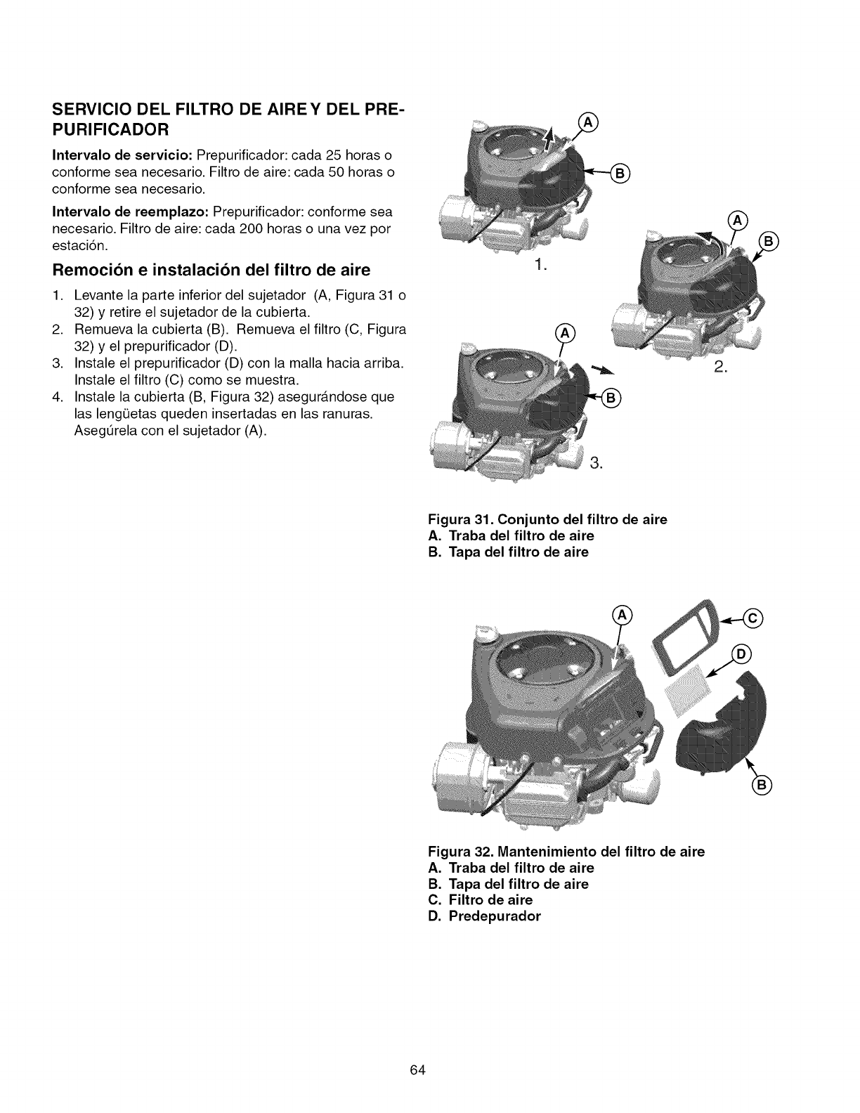
SERVICIO DEL FILTRO DE AIREY DEL PRE-
PURIFICADOR
Intervalo de servicio: Prepurificador: cada 25 horas o
conforme sea necesario. Filtro de aire: cada 50 horas o
conforme sea necesario.
Intervalo de reemplazo: Prepurificador: conforme sea
necesario. Filtro de aire: cada 200 horas o una vez por
estaci6n.
Remocibn e instalacibn del filtro de aire
1. Levante la parte inferior del sujetador (A, Figura 31 o
32) y retire el sujetador de la cubierta.
2. Remueva la cubierta (B). Remueva el filtro (C, Figura
32) y el prepurificador (D).
3. Instale el prepurificador (D) con la malla hacia arriba.
Instale el filtro (C) como se muestra.
4. Instale la cubierta (B, Figura 32) asegur&ndose que
las leng0etas queden insertadas en las ranuras.
Aseg_rela con el sujetador (A).
I =
=
=
Figura 31. Conjunto del filtro de aire
A. Traba del filtro de aire
B. Tapa del filtro de aire
®
Figura 32. Mantenimiento del filtro de aire
A. Traba del filtro de aire
B. Tapa del filtro de aire
C. Filtro de aire
D. Predepurador
64
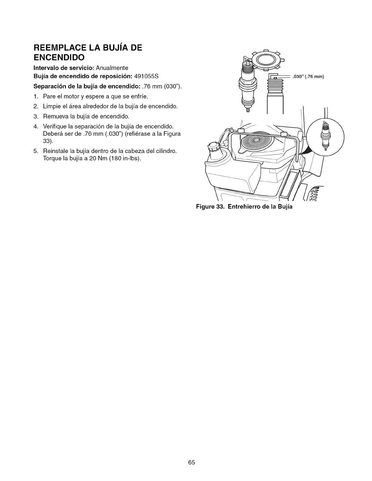
REEMPLACE LA BUJJA DE
ENCENDIDO
Intervalo de servicio: Anualmente
Bujia de encendido de reposici6n: 491055S
Separaci6n de la bujia de encendido: .76 mm (030").
1. Pare el motor y espere a que se enfr_e.
2. Limpie el Area alrededor de la bujfa de encendido.
3. Remueva la bujfa de encendido.
4. Verifique la separaci6n de la bujfa de encendido.
Deber& set de .76 mm (.030") (refierase a la Figura
33).
5. Reinstale la bujfa dentro de la cabeza del cilindro.
Torque la bujfa a 20 Nm (180 in-lbs).
.030" (.76 ram)
Figure 33. Entrehierro de la Bujia
65
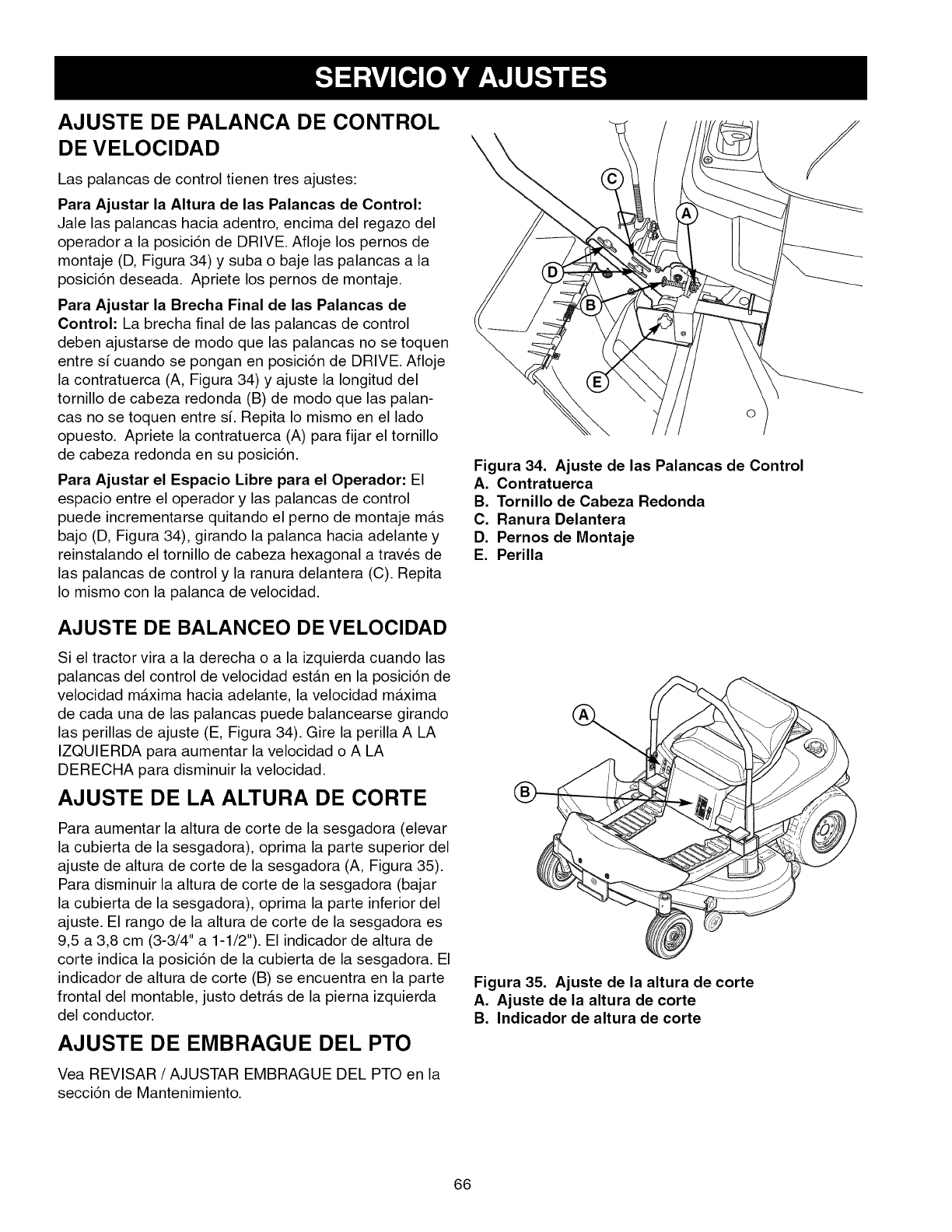
AJUSTE DE PALANCA DE CONTROL
DE VELOCIDAD
Las palancas de control tienen tres ajustes:
Para Ajustar la Altura de las Palancas de Control:
Jale las palancas hacia adentro, encima del regazo del
operador a la posici6n de DRIVE. Afloje los pernos de
montaje (D, Figura 34) y suba o baje las palancas a la
posici6n deseada. Apriete los pernos de montaje.
Para Ajustar la Brecha Final de las Palancas de
Control: La brecha final de las palancas de control
deben ajustarse de modo que las palancas no se toquen
entre si cuando se pongan en posici6n de DRIVE. Afloje
la contratuerca (A, Figura 34) y ajuste la Iongitud del
tornillo de cabeza redonda (B) de modo que las palan-
cas no se toquen entre si. Repita Io mismo en el lado
opuesto. Apriete la contratuerca (A) para fijar el tornillo
de cabeza redonda en su posici6n.
Para Ajustar el Espacio Libre para el Operador: El
espacio entre el operador y las palancas de control
puede incrementarse quitando el perno de montaje mAs
bajo (D, Figura 34), girando la palanca hacia adelante y
reinstalando el tornillo de cabeza hexagonal a traves de
las palancas de control y la ranura delantera (C). Repita
Io mismo con la palanca de velocidad.
AJUSTE DE BALANCEO DE VELOCIDAD
Si el tractor vira a la derecha o a la izquierda cuando las
palancas del control de velocidad estan en la posici6n de
velocidad maxima hacia adelante, la velocidad maxima
de cada una de las palancas puede balancearse girando
las perillas de ajuste (E, Figura 34). Gire la perilla A LA
IZQUIERDA para aumentar la velocidad o A LA
DERECHA para disminuir la velocidad.
AJUSTE DE LA ALTURA DE CORTE
Para aumentar la altura de corte de la sesgadora (elevar
la cubierta de la sesgadora), oprima la parte superior del
ajuste de altura de corte de la sesgadora (A, Figura 35).
Para disminuir la altura de corte de la sesgadora (bajar
la cubierta de la sesgadora), oprima la parte inferior del
ajuste. El rango de la altura de corte de la sesgadora es
9,5 a 3,8 cm (3-3/4" a 1-1/2"). El indicador de altura de
corte indica la posici6n de la cubierta de la sesgadora. El
indicador de altura de corte (B) se encuentra en la parte
frontal del montable, justo detrAs de la pierna izquierda
del conductor.
AJUSTE DE EMBRAGUE DEL PTO
Vea REVISAR /AJUSTAR EMBRAGUE DEL PTO en la
secci6n de Mantenimiento.
\
O
Figura 34. Ajuste de las Palancas de Control
A. Contratuerca
B. Tornillo de Cabeza Redonda
C. Ranura Delantera
D. Pernos de Montaje
E. Perilla
Figura 35. Ajuste de la altura de corte
A. Ajuste de la altura de corte
B. Indicador de altura de corte
66
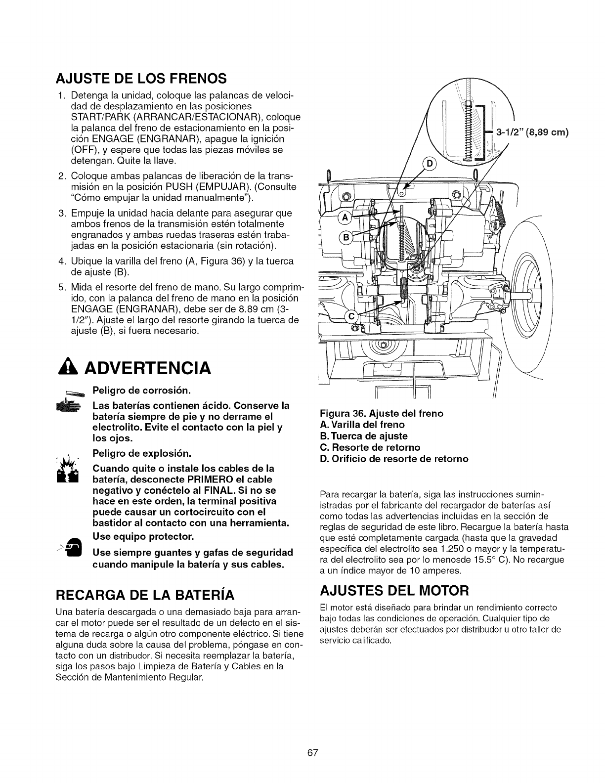
AJUSTE DE LOS FRENOS
1. Detenga la unidad, coloque las palancas de veloci-
dad de desplazamiento en las posiciones
START/PARK (ARRANCAR/ESTACIONAR), coloque
la palanca del freno de estacionamiento en la posi-
ci6n ENGAGE (ENGRANAR), apague la ignici6n
(OFF), y espere que todas las piezas m6viles se
detengan. Quite la Ilave.
2. Coloque ambas palancas de liberaci6n de la trans-
misi6n en la posici6n PUSH (EMPUJAR). (Consulte
"C6mo empujar la unidad manualmente").
3. Empuje la unidad hacia delante para asegurar que
ambos frenos de la transmisi6n est_n totalmente
engranados y ambas ruedas traseras esten traba-
jadas en la posici6n estacionaria (sin rotaci6n).
4. Ubique la varilla del freno (A, Figura 36) y la tuerca
de ajuste (B).
5. Mida el resorte del freno de mano. Su largo comprim-
ido, con la palanca del freno de mano en la posici6n
ENGAGE (ENGRANAR), debe set de 8.89 cm (3-
1/2"). Ajuste el largo del resorte girando la tuerca de
ajuste (B), si fuera necesario.
3=1/2" (8,89 cm)
ADVERTENCIA
Peligro de corrosi6n.
Las baterias contienen _cido. Conserve la
bateria siempre de pie y no derrame el
electrolito. Evite el contacto con la piel y
losojos.
Peligro de explosi6n.
Cuando quite o instale los cables de la
bateria, desconecte PRIMERO el cable
negativo y con_ctelo al FINAL. Si no se
hace en este orden, la terminal positiva
puede causar un cortocircuito con el
bastidor al contacto con una herramienta.
Use equipo protector.
Use siempre guantes y gafas de seguridad
cuando manipule la bateria y sus cables.
RECARGA DE LA BATERJA
Una baterfa descargada o una demasiado baja para arran-
car el motor puede ser el resultado de un defecto en el sis-
tema de recarga o algt_n otro componente electrico. Si tiene
alguna duda sobre la causa del problema, p6ngase en con-
tacto con un distribudor. Si necesita reemplazar la baterfa,
siga los pasos bajo Limpieza de Bateria y Cables en la
Secci6n de Mantenimiento Regular.
Figura 36. Ajuste del freno
A. Varilla del freno
B. Tuerca de ajuste
C. Resorte de retorno
D. Orificio de resorte de retorno
Para recargar la baterfa, siga las instrucciones sumin-
istradas por el fabricante del recargador de baterfas asi
como todas las advertencias incluidas en la secci6n de
reglas de seguridad de este libro. Recargue la baterfa hasta
que este completamente cargada (hasta que la gravedad
especifica del electrolito sea 1.250 o mayor y la temperatu-
ra del electrolito sea por Io menosde 15.5 ° C). No recargue
a un indice mayor de 10 amperes.
AJUSTES DEL MOTOR
El motor esta diseSado para brindar un rendimiento correcto
bajo todas las condiciones de operaci6n. Cualquier tipo de
ajustes deberan ser efectuados por distribudor u otro taller de
servicio calificado.
67
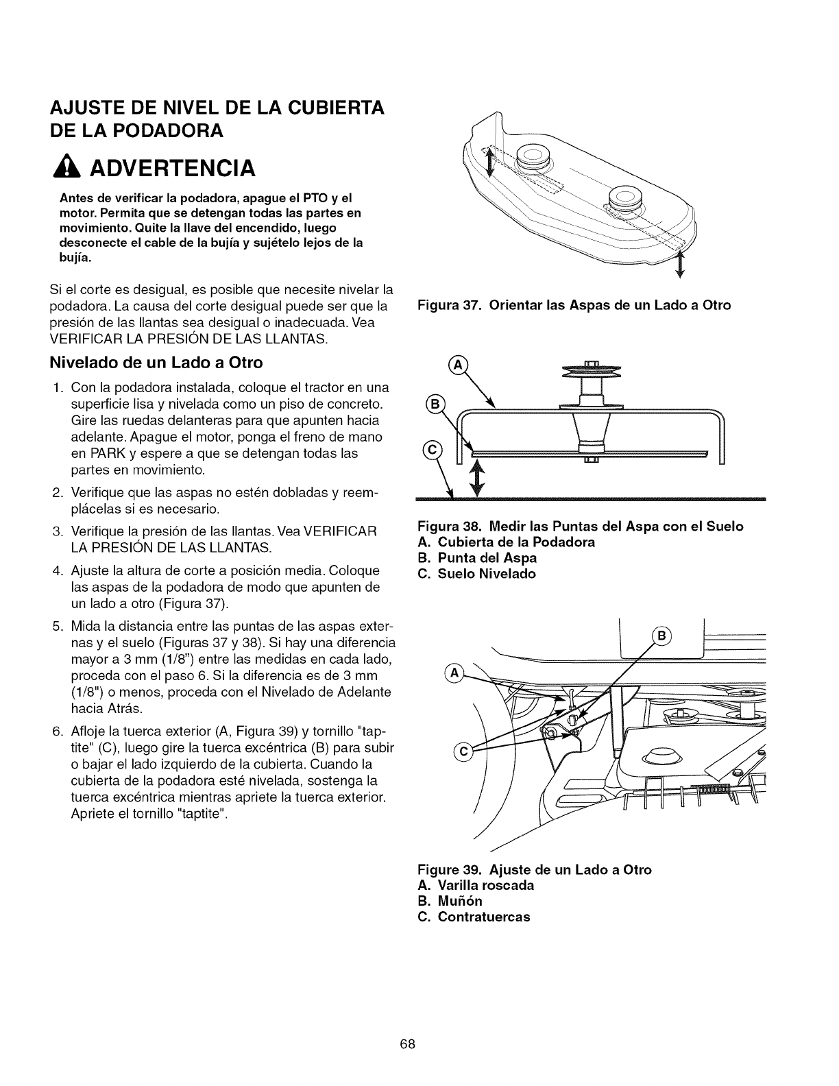
AJUSTE DE NIVEL DE LA CUBIERTA
DE LA PODADORA
ADVERTENCIA
Antes de verificar la podadora, apague el PTO y el
motor. Permita que se detengan todas las partes en
movimiento. Quite la Ilave del encendido, luego
desconecte el cable de la bujia y suj_telo lejos de la
bujia.
Si el corte es desigual, es posible que necesite nivelar la
podadora. La causa del corte desigual puede set que la
presi6n de las Ilantas sea desigual o inadecuada. Vea
VERIFICAR LA PRESION DE LAS LLANTAS.
Nivelado de un Lado a Otro
1. Con la podadora instalada, coloque el tractor en una
superficie lisa y nivelada como un piso de concreto.
Gire las ruedas delanteras para que apunten hacia
adelante. Apague el motor, ponga el freno de mano
en PARK y espere a que se detengan todas las
partes en movimiento.
2. Verifique que las aspas no esten dobladas y reem-
pl&celas si es necesario.
3. Verifique la presi6n de las Ilantas. Vea VERIFICAR
LA PRESION DE LAS LLANTAS.
,
,
,
Ajuste la altura de corte a posici6n media. Coloque
las aspas de la podadora de modo que apunten de
un lado a otto (Figura 37).
Mida la distancia entre las puntas de las aspas exter-
nas y el suelo (Figuras 37 y 38). Si hay una diferencia
mayor a 3 mm (1/8") entre las medidas en cada lado,
proceda con el paso 6. Si la diferencia es de 3 mm
(1/8") o menos, proceda con el Nivelado de Adelante
hacia Atr&s.
Afloje la tuerca exterior (A, Figura 39) y tornillo "tap-
tite" (C), luego gire la tuerca excentrica (B) para subir
o bajar el lado izquierdo de la cubierta. Cuando la
cubierta de la podadora este nivelada, sostenga la
tuerca excentrica mientras apriete la tuerca exterior.
Apriete el tornillo "taptite".
Figura 37. Orientar las Aspas de un Lado a Otro
\
.....LLJL!'_
Figura 38. Medir las Puntas del Aspa con el Suelo
A. Cubierta de la Podadora
B. Punta del Aspa
C. Suelo Nivelado
Figure 39. Ajuste de un Lado a Otro
A. Varilla roscada
B. Mu56n
C. Contratuercas
68
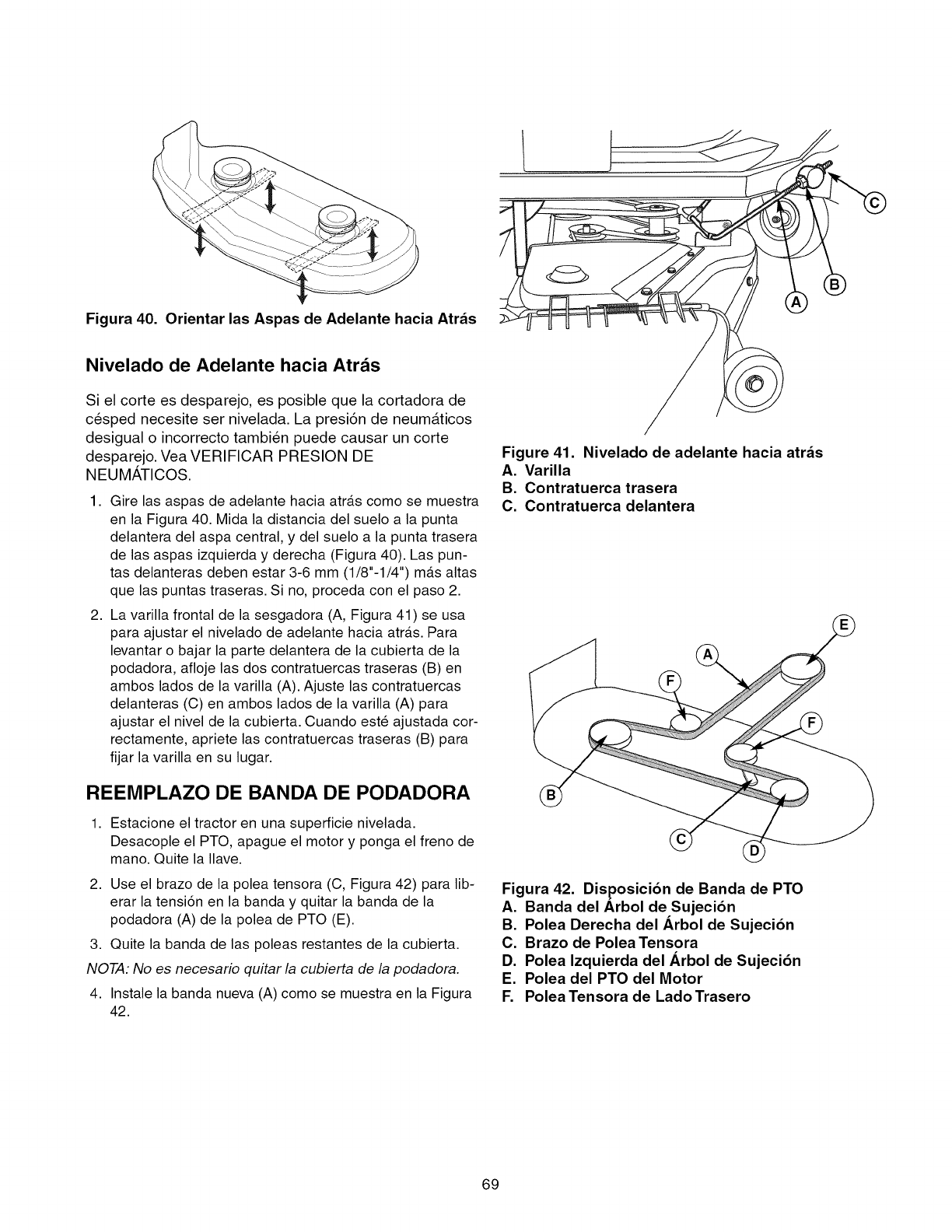
Figura 40. Orientar las Aspas de Adelante hacia Atr_s
Nivelado de Adelante hacia Atras
Si el corte es desparejo, es posible que la cortadora de
cesped necesite set nivelada. La presiSn de neum&ticos
desigual o incorrecto tambien puede causar un corte
desparejo. Vea VERIFICAR PRESION DE
NEUMATICOS.
,
2,
Gire las aspas de adelante hacia atr_ts como se muestra
en la Figura 40. Mida la distancia del suelo a la punta
delantera del aspa central, y del suelo a la punta trasera
de las aspas izquierda y derecha (Figura 40). Las pun-
tas delanteras deben estar 3-6 mm (1/8"-1/4") m_ts altas
que las puntas traseras. Si no, proceda con el paso 2.
La varilla frontal de la sesgadora (A, Figura 41) se usa
para ajustar el nivelado de adelante hacia atr_ts. Para
levantar o bajar la parte delantera de la cubierta de la
podadora, afloje las dos contratuercas traseras (B) en
ambos lados de la varilla (A). Ajuste las contratuercas
delanteras (C) en ambos lados de la varilla (A) para
ajustar el nivel de la cubierta. Cuando este ajustada cor-
rectamente, apriete las contratuercas traseras (B) para
fijar la varilla en su lugar.
REEMPLAZO DE BANDA DE PODADORA
1, Estacione el tractor en una superficie nivelada.
Desacople el PTO, apague el motor y ponga el freno de
mane. Quite la Ilave.
2. Use el brazo de la polea tensora (C, Figura 42) para lib-
erar la tensi6n en la banda y quitar la banda de la
podadora (A) de la polea de PTO (E).
3. Quite la banda de las poleas restantes de la cubierta.
NOTA: No es necesario quitar la cubierta de la podadora.
4. Instale la banda nueva (A) come se muestra en la Figura
42.
Figure 41. Nivelado de adelante hacia atr_s
A. Varilla
B. Contratuerca trasera
C. Contratuerca delantera
Figura 42. Disposici6n de Banda de PTO
A. Banda del Arbol de Sujeci6n
B. Polea Derecha del Arbol de Sujeci6n
C. Brazo de Polea Tensora
D. Polea Izquierda del Arbol de Sujeci6n
E. Polea del PTO del Motor
F. PoleaTensora de LadoTrasero
69
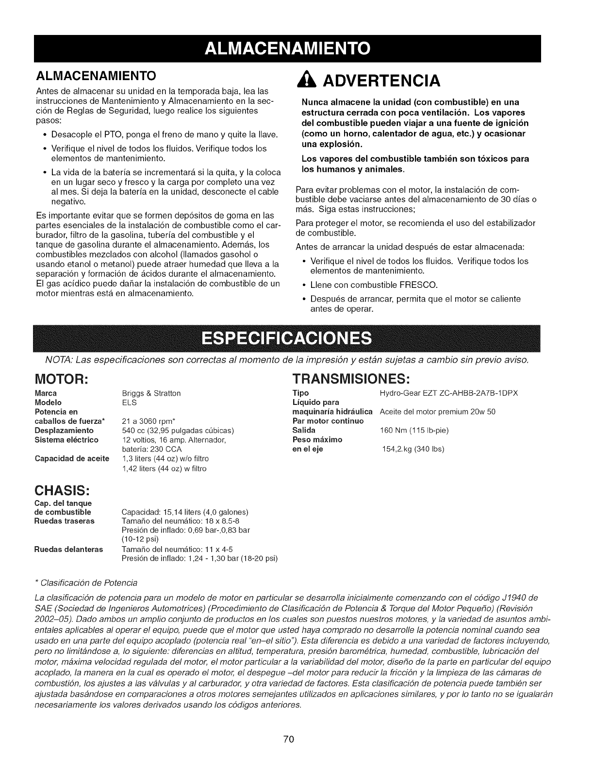
ALMACENAMIENTO
Antes de almacenar su unidad en la temporada baja, lea las
instrucciones de Mantenimiento y Almacenamiento en la sec-
ci6n de Reglas de Seguridad, luego realice los siguientes
pasos:
• Desacople el PTO, ponga el freno de mano y quite la Ilave.
• Verifique el nivel de todos los fluidos. Verifique todos los
elementos de mantenimiento.
• La vida de la bateria se incrementara si la quita, y la coloca
en un lugar seco y fresco y la carga por completo una vez
al mes. Si deja la bateria en la unidad, desconecte el cable
negativo.
Es importante evitar que se formen dep6sitos de goma en las
partes esenciales de la instalaci6n de combustible como el car-
burador, filtro de la gasolina, tuberia del combustible y el
tanque de gasolina durante el almacenamiento. Ademas, los
combustibles mezclados con alcohol (llamados gasohol o
usando etanol o metanol) puede atraer humedad que Ileva a la
separaci6n y formaci6n de acidos durante el almacenamiento.
El gas acidico puede daSar la instalaci6n de combustible de un
motor mientras esta en almacenamiento.
ADVERTENCIA
Nunca almacene la unidad (con combustible) en una
estructura cerrada con poca ventilacion. Los vapores
del combustible pueden viajar a una fuente de ignicion
(como un horno, calentador de agua, etc.) y ocasionar
una explosion.
Los vapores del combustible tambi_n son toxicos para
los humanos y animales.
Para evitar problemas con el motor, la instalaci6n de com-
bustible debe vaciarse antes del almacenamiento de 30 dias o
mas. Siga estas instrucciones;
Para proteger el motor, se recomienda el uso del estabilizador
de combustible.
Antes de arrancar la unidad despu@s de estar almacenada:
• Verifique el nivel de todos los fluidos. Verifique todos los
elementos de mantenimiento.
• Llene con combustible FRESCO.
• Despu@s de arrancar, permita que el motor se caliente
antes de operar.
NOTA: Las especificaciones son correctas al momento de la impresi6n y estbn sujetas a cambio sin previo aviso.
MOTOR: TRANSMISIONES:
Marca Briggs & Stratton Tipo
Modelo ELS Liquido para
Potencia en maquinaria hidr_ulica
caballos de fuerza* 21 a 3060 rpm* Par motor eontinuo
Desplazamiento 540 cc (32,95 pulgadas cObicas) Salida
Sistema el_ctrico 12voltios, 16 amp.AIternador, Peso m_ximo
bateria: 230 CCA en el eje
1,3 liters (44 oz) w/o filtro
1,42 liters (44 oz) w filtro
Capacidad de aceite
Hydro-Gear EZT ZC-AHBB-2A7B-1DPX
Aceite del motor premium 20w 50
160 Nm (115 Ib-pie)
154,2. kg (340 Ibs)
CHASIS:
Cap. del tanque
de combustible
Ruedas traseras
Ruedas delanteras
Capacidad: 15,14 liters (4,0 galones)
Tamale del neumgltico: 18 x 8.5-8
Presi6n de infiado: 0,69 bar-,0,83 bar
(10-12 psi)
Tamale del neumatico: 11 x 4-5
Presi6n de infiado: 1,24 -1,30 bar (18-20 psi)
* Clasificaci6n de Potencia
La clasificaci6n de potencia para un modelo de motor en particular se desarrolla inicialmente comenzando con el c6digo J1940 de
SAE (Sociedad de Ingenieros Automotrices) (Procedimiento de Clasificaci6n de Potencia & Torque del Motor Peque#o) (Revisi6n
2002-05). Dado ambos un ampfio conjunto de productos en los cuales son puestos nuestros motores, y la variedad de asuntos ambi-
entales apficables al operar el equipo, puede que el motor que usted haya comprado no desarrolle la potencia nominal cuando sea
usado en una parte del equipo acoplado (potencia real "en-el sitio"). Esta diferencia es debido a una variedad de factores incluyendo,
pero no limitbndose a, Io siguiente: diferencias en altitud, temperatura, presi6n barom@trica, humedad, combustible, lubricaci6n del
motor, mbxima velocidad regulada del motor, el motor particular a la variabilidad del motor, dise#o de la parte en particular del equipo
acoplado, la manera en la cual es operado el motor, el despegue -del motor para reducir la fricci6n y la limpieza de las cbmaras de
combusti6n, los ajustes a las vblvulas y al carburador, y otra variedad de factores. Esta clasificaci6n de potencia puede tambi@n ser
ajustada basbndose en comparaciones a otros motores semejantes utilizados en aplicaciones similares, y por Io tanto no se igualarbn
necesariamente los valores derivados usando los c6digos anteriores.
70

ADVERTENCIA
Para evitar lesiones graves, realice el mantenimiento del tractor o la
podadora solo con el motor apagado y el freno de mano en PARK.
Siempre quite la Ilave del encendido, desconecte el cable de la bujia
y suj_telo lejos de la bujia antes de empezar con el mantenimiento,
para evitar que el motor arranque accidentalmente.
Si Io prefiere, todos estos procedimientos
pueden ser ejecutados para usted por un
Centro de Partes y Reparaciones de dis-
tribudor.
Diagn6stico del Tractor
PROBLEIVIA CAUSA
El motor no Las palancas de velocidad de avance no estan
rota ni en START/PARK (arrancar).
arranca. La cuchilla de la sesgadora esta activada.
Las palancasdevelocidadnoestanen START/PARK.
El ahogador no esta en posici6n de CLOSED.
El interruptor de encendido no esta en START.
No tiene combustible.
Motor ahogado.
El combustible esta viejo o viciado, o hay agua
en el combustible.
Bateria descargada.
Bujias defectuosas,sucias o con entrehierroincorrecto.
Cableado suelto o roto.
Solenoide o motor de arranque defectuoso.
Interruptor del intercierre defectuoso.
Interruptor del intercierre de seguridad defectuoso.
Filtro de aire obstruido.El motor
arranca difi-
cil o no fun-
ciona bien. Ahogador sin colocar en la posici6n CLOSED
(cerrado) durante el arranque del motor, o el
ahogador sin colocar en la posici6n OPEN
(abierto) despu6s de que el motor haya arran-
cado.
REIVIEDIO
Col6quelas en START/PARK (arrancar).
Desactivela.
Col6quelas en START/PARK (arrancar).
Mueva el ahogador a la posici6n de CLOSED.
Gire el interruptor de encendido a la posici6n de START.
Deje enfriar el motor y Ilene de nuevo el tanque de
combustible.
Coloque el ahogador en posici6n de OPEN (abierto)
cuando d6 marcha al motor.
Drene el combustible y Ilene con gasolina fresca.
Comuniquese con Piezas y Reparaciones de Sears.
Recargue o reemplace la bated&
Limpie y ajuste a entrehierro o reemplace.
Revise el cableado y reemplace los cables rotos o
raidos. Apriete las conexiones sueltas.
Reemplace. Comuniquese con Piezas y
Reparaciones de Sears.
Reemplace. Comuniquese con Piezas y
Reparaciones de Sears.
Reemplace.Contacte Partesy Reparacionesde Sears.
D6 servicio al pre-limpiador y/o reemplace el ele-
mento del filtro de aire.
Coloque el ahogador en la posici6n CLOSED (cerra-
do) durante el arranque del motor. Coloque el
ahogador en la posici6n OPEN (abierto) cuando el
motor est6 andando. Si el motor esta caliente no
requerira ser ahogado.
Bujia defectuosa, sucia o con entrehierro incorrecto. Limpie y ajuste a entrehierro o reemplace.
Motor Nivel del aceite bajo. Verifique/agregue aceite segOn se requiera.
golpetea. Uso de aceite de grado incorrecto. Vea "Cambiar el Aceite del Motor" en la Secci6n de
Mantenimiento.
Excesivo Motor se calienta demasiado mientras opera. Limpie el abanico de enfriamiento del motor, la rejilla
consumo de sopladora y el limpiador de aire.
aceite. Uso de aceite de peso incorrecto. Vea "Cambiar el Aceite del Motor" en la Secci6n de
Mantenimiento.
Demasiado aceite en el carter. Drene el aceite excedente.
El humo del Filtro de aire sucio. Reemplace el filtro de aire. Yea "Reemplazar el
escape del Elemento del Filtro de Aire".
motor es Control del ahogador en posici6n de cerrado. Abra el control del ahogador.
neg to.
71

Elmotoropera Laspalancasdedesembraguedela Muevalaspalancasalaposici6ndeDRIVE.
peroeltractor transmisi6nenposici6ndeEMPUJAR.
no avanza. La banda de tracci6n se barre. Limpie o reemplace la banda segL_nsea necesario.
La banda esta rota. Reemplace banda. Contacte Partesy Reparacionesde Sears.
Freno de mano no esta desaccionado. Contacte Partes y Reparaciones de Sears.
Banda de trac= Poleas o la banda con grasa o aceite. Limpie segL_nse requiera.
ci6n se barre. La banda esta estirada o desgastada. Reemplace banda. Contacte Partesy Reparacionesde Sears.
El freno de mano El freno de mano esta mal ajustado. Vea la Secci6n de Ajustes.
no se mantiene.
Tractor se direc- Inflado inadecuado de las Ilantas. Vea la Secci6n de Mantenimiento.
ciona o rnaneja
con deficiencia. Acoplamiento de direcci6n esta flojo. Verifique y apriete las conexiones sueltas.
Tractor estira Las perillas de ajuste de velocidad no Vea AJUSTE DE BALANCEO DE VELOCIDAD.
para un lado. estan ajustadas.
Diagn6stico de la sesgadora
PROBLEIVIA CAUSA REIVIEDIO
Es dificil ajustar la El tornillo del motor para la altura de Limpie a conciencia y lubrique la manivela de altura
altura de corte de corte esta sucio o necesita lubricarse, de corte con aceite.
la sesgadora. Mecanismo para la altura de corte Reconecte el mecanismo para la altura de corte.
desconectado.
El corte de la ses= Las Ilantas del montable no estan Vea la secci6n de Mantenimiento.
gadora es desigual, infiadas de manera correcta o uniforme.
La sesgadora no esta debidamente nivelada. Vea "Nivelado de la Sesgadora" en Servicio y ajustes.
El corte de la ses= La velocidad del motor es muy lenta. Siempre ponga el acelerador en FAST cuando pode
gadora es de el c6sped.
aspecto tosco. La velocidad de avance es muy alta. Disminuya la velocidad.
Las cuchillas estan desafiladas. Afile o reemplace las cuchillas. Vea la secci6n de
Mantenimiento.
La banda de tracci6n se barre porque Limpie o reemplace la banda segL_nsea necesario.
tiene aceite o esta desgastada.
Las cuchillas no estan debidamente aft= Vea "Revisar/Ajustar Cuchillas de Sesgadora" en la
anzadas al arbol de sujeci6n, secci6n de Mantenimiento.
El motor se atasca La velocidad del motor es muy lenta. Siempre ponga el acelerador en FAST al podar el c6sped.
con facilidad con la La velocidad de avance es muy alta. Disminuya la velocidad.
sesgadora activa=
da. La altura de corte es muy baja. Corte el c6sped alto con la altura maxima de corte
en la primera pasada.
Lado inferior de la cubierta esta sucio. Quite la cubierta de la sesgadora y limpie el lado inferior.
La tolva de expulsi6n se atasca con la Corte el c6sped con la expulsi6n apuntando hacia
hierba cortada, el area anteriormente cortada.
Vibraci6n excesiva Pernos de montaje de las cuchillas flojos. Apriete a 61-75 Nm (45-55 ft-lbs).
de la sesgadora. Las cuchillas, arboles de sujeci6n o Revise y reemplace segL_nsea necesario.
poleas estan doblados.
Las cuchillas de la sesgadora estan fuera Reemplace o equilibre las cuchillas. Vea la secci6n
de equilibrio, de Mantenimiento.
Banda instalada incorrectamente. Reinstale correctamente.
La banda de trac- El resorte de la polea tensora esta roto o Repare o reemplace segL_nsea necesario.
ci6n de la sesgado= no esta debidamente fijo.
ra se barre o no La banda de tracci6n esta rota. Reemplace la banda de tracci6n.
impulsa. Embrague del PTO fuera de ajuste. AjusteelembraguedelPTO.Vealasecci6ndeMantenimiento.
72

RepairParts
PTS - 1
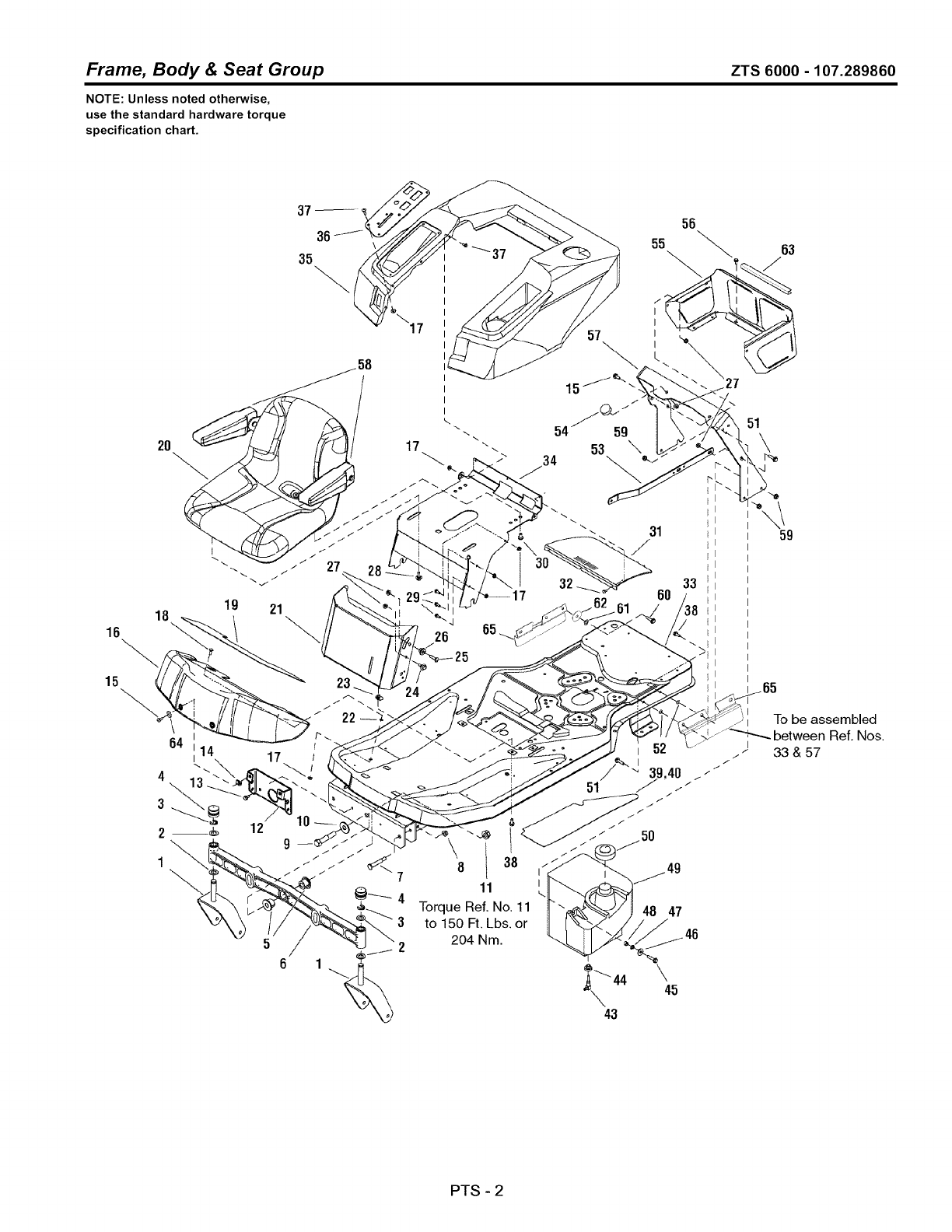
Frame, Body & Seat Group ZTS 6000 -107.289860
NOTE: Unless noted otherwise,
use the standard hardware torque
specification chart.
16
15
18 19 21
64 =14
,\
1
17
12 9
65
26
8 1 38
11
Torque Ref. No, 11
to 150 Ft. Lbs, or
204 Nm.
15 t
53 \
-\
51
31 59
33
60 ,
>;
To be assembled
between Ref. Nos.
33 & 57
48 47
\45
PTS - 2
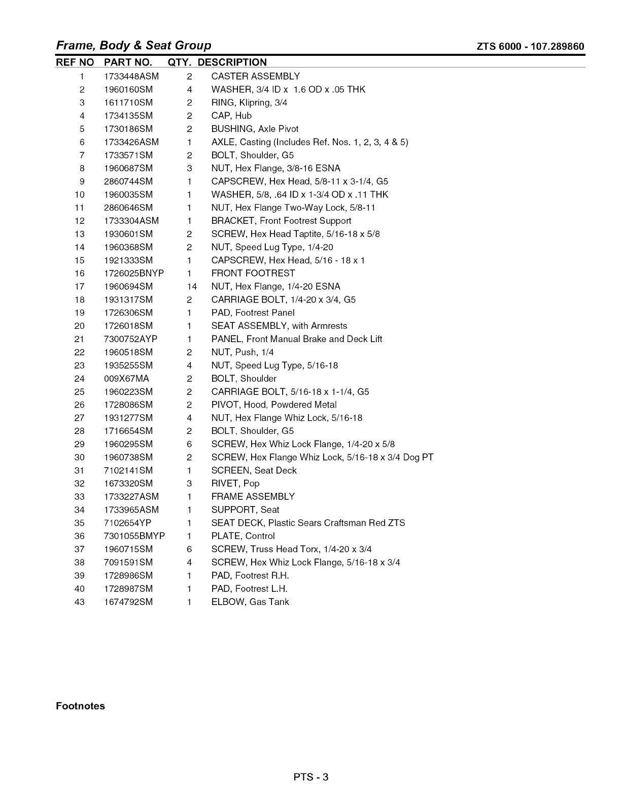
Frame, Body & Seat Group
REF NO PART NO. QTY.
1 1733448ASM 2
2 1960160SM 4
3 1611710SM 2
4 1734135SM 2
5 1730186SM 2
6 1733426ASM 1
7 1733571SM 2
8 1960687SM 3
9 2860744SM 1
10 1960035SM 1
11 2860646SM 1
12 1733304ASM 1
13 1930601SM 2
14 1960368SM 2
15 1921333SM 1
16 1726025BNYP 1
17 1960694SM 14
18 1931317SM 2
19 1726306SM 1
20 1726018SM 1
21 7300752AYP 1
22 1960518SM 2
23 1935255SM 4
24 009X67MA 2
25 1960223SM 2
26 1728086SM 2
27 1931277SM 4
28 1716654SM 2
29 1960295SM 6
30 1960738SM 2
31 7102141SM 1
32 1673320SM 3
33 1733227ASM 1
34 1733965ASM 1
35 7102654YP 1
36 7301055BMYP 1
37 1960715SM 6
38 7091591SM 4
39 1728986SM 1
40 1728987SM 1
43 1674792SM 1
DESCRIPTION
CASTER ASSEMBLY
WASHER, 3/41Dx 1.6ODx.05THK
RING, Klipring, 3/4
CAP, Hub
BUSHING, Axle Pivot
AXLE, Casting (Includes Ref. Nos. 1,2, 3, 4 & 5)
BOLT, Shoulder, G5
NUT, Hex Flange, 3/8-16 ESNA
CAPSCREW, Hex Head, 5/8-11 x 3-1/4, G5
WASHER, 5/8, .64 ID x 1-3/40D x .11 THK
NUT, Hex Flange Two-Way Lock, 5/8-11
BRACKET, Front Footrest Support
SCREW, Hex Head Taptite, 5/16-18 x 5/8
NUT, Speed Lug Type, 1/4-20
CAPSCREW, Hex Head, 5/16 - 18 x 1
FRONT FOOTREST
NUT, Hex Flange, 1/4-20 ESNA
CARRIAGE BOLT, 1/4-20 x 3/4, G5
PAD, Footrest Panel
SEAT ASSEMBLY, with Armrests
PANEL, Front Manual Brake and Deck Lift
NUT, Push, 1/4
NUT, Speed Lug Type, 5/16-18
BOLT, Shoulder
CARRIAGE BOLT, 5/16-18 x 1-1/4, G5
PIVOT, Hood, Powdered Metal
NUT, Hex Flange Whiz Lock, 5/16-18
BOLT, Shoulder, G5
SCREW, Hex Whiz Lock Flange, 1/4-20 x 5/8
SCREW, Hex Flange Whiz Lock, 5/16-18 x 3/4 Dog PT
SCREEN, Seat Deck
RIVET, Pop
FRAME ASSEMBLY
SUPPORT, Seat
SEAT DECK, Plastic Sears Craftsman Red ZTS
PLATE, Control
SCREW, Truss Head Torx, 1/4-20 x 3/4
SCREW, Hex Whiz Lock Flange, 5/16-18 x 3/4
PAD, Footrest R.H.
PAD, Footrest L.H.
ELBOW, Gas Tank
ZTS 6000 - 107.289860
Footnotes
PTS - 3

Frame, Body & Seat Group ZTS 6000 -107.289860
NOTE: Unless noted otherwise,
use the standard hardware torque
specification chart.
16
15
18 19 21
64 =14
,\
1
17
12 9
65
26
8 1 38
11
Torque Ref. No, 11
to 150 Ft. Lbs, or
204 Nm.
15 t
53 \
-\
51
31 59
33
60 ,
>;
To be assembled
between Ref. Nos.
33 & 57
48 47
\45
PTS - 4

Frame, Body & Seat Group
REF NO PART NO. QTY.
44 1726400SM 1
45 1921221SM 1
46 1919381SM 1
47 7090189SM 1
48 7024340SM 1
49 7102860YP 1
50 1734320SM 1
51 1921977SM 5
52 1933988SM 4
53 1727810ASM 1
54 1726390SM 2
55 1715962ASM 1
56 1925003SM 6
57 1733393ASM 1
58 1687021SM 1
59 1960686SM 9
60 1920415SM 1
61 1931942SM 1
62 1960534SM 1
63 7070814SM 1
64 1921880SM 2
65 1734392ASM 2
ZTS 6000 -107.289860
DESCRIPTION
BUSHING, Fuel
CAPSCREW, 5/16, 18 x 1-1/2
WASHER, 5/16, .34 ID x 10D x .13 THK
LOCKWASHER, External Tooth, 3/8
SPACER
TANK, Fuel
CAP, Fuel Tank
CAPSCREW, Hex Head, 5/16-18 x 1-1/4, G5
NUT, Push Pal, 5/16 DIA Thread, 5/80D
BRACE, Tank
BUMPER, Rubber
SHROUD, Rear
SCREW, Hex Washer Head Taptite, 1/4-20 x 1/2
SUPPORT, Seat Deck
ARM REST KIT, L.H. & R.H.
NUT, Hex Flange Nylock, 5/16-18
CAPSCREW, 3/8 - 16 x 1-1/4
NUT, Push Pal, 3/8
WASHER, 3/8
TRIM, 8"
WASHER, External Tooth, 1/4
GUARD, Debris
Footnotes
PTS - 5
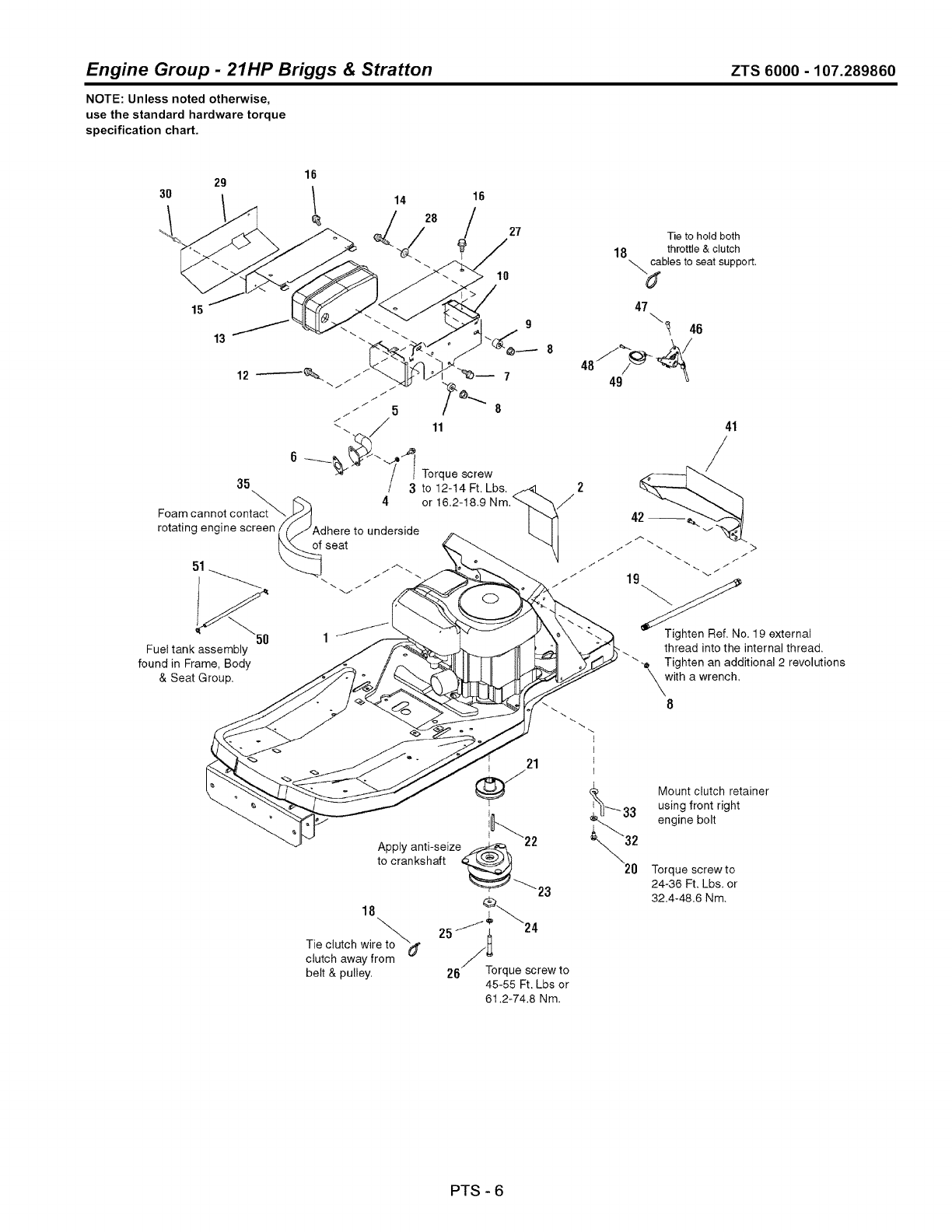
Engine Group -21HP Briggs & Stratton ZTS 6000- 107.289860
NOTE: Unless noted otherwise,
use the standard hardware torque
specification chart.
3O 29
15
13 _
35
Foam cannot contact_
rotating engine screen
51
14 16
<28 I
10
I
I Torque screw
3to 12-14 Ft. Lbs.
4or
27
to underside
Fuel tank assembly
found in Frame, Body
& Seat Group,
/
Tie to hold both
18 throttle & clutch
"_bles to seat support,
47
_46
41
19
Tighten Ref, No. 19 external
thread into the internal thread,
Tighten an additional 2 revolutions
with a wrench,
8
21
Apply anti-seize_ 22
to crankshaft
18
belt & pulley,
®
257i _24
26 Torque screw to
45-55 Ft. Lbs or
61.2-74.8 Nm.
Mount clutch retainer
using front right
engine bolt
Torque screw to
24-36 Ft, Lbs, or
32.4-48,6 Nm,
PTS - 6

Engine Group -21HP Briggs & Stratton
REF NO PART NO. QTY.
1 33M7770111 B1 1
2 7300919ASM 1
3 1936228SM 2
4 1917356SM 2
5 1732259SM 1
6 1731214SM 1
7 1960295SM 4
8 1927557SM 4
9 1667812SM 1
10 7300917SM 1
11 1667811SM 1
12 1921977SM 1
13 1732273SM 1
14 1921221SM 1
15 7300918ASM 1
16 1960720SM 4
18 2832747SM 2
19 1726498SM 1
20 2828635SM 3
21 7101716SM 1
22 1720463SM 1
23 1686880SM 1
24 1708264SM 1
25 1918199SM 1
26 7027266SM 1
27 1732885ASM 1
28 1919326SM 2
29 1733063SM 1
30 1675044SM 2
32 1924940SM 1
33 7101717SM 1
35 7102139SM 1
41 1734180ASM 1
42 1921332SM 1
46 7103123YP 1
47 7090999SM 2
48 7091195SM 1
49 7100529SM 1
50 1734984SM 1
51 2860112SM 2
ZTS 6000 -107.289860
DESCRIPTION
ENGINE, 21HP B&S Intek, 49 State * (Model - 33M777, Type - 0111, Trim - B1)
HEAT SHIELD, Inner
CAPSCREW, Hex Head, 5/16-18 x 3/4, G8
LOCKWASHER, Spring, 5/16
PIPE ASSEMBLY, Exhaust
GASKET, Exhaust
SCREW, Hex Whiz Lock Flange, 1/4-20 x 5/8
NUT, Hex Whiz Lock Flange, 5/16-18
SPACER
BRACKET, Muffler/Heat Shield
SPACER, .390 ID x .90D x .34 LG, Powdered Metal
CAPSCREW, Hex Head, 5/16-18 x 1-1/4, G5
MUFFLER ASSEMBLY, Single
CAPSCREW, Hex Head, 5/16-18 x 1-1/2, G5
HEAT SHIELD, Outer Single
CAPSCREW, Thread Cutting, # 10 x 1/2
TIE, Self Locking, 3-5/8 LG
HOSE, Oil Drain, 16-1/2 LG
SCREW, Hex Washer Head Taptite, 3/8-16 x 1-1/4
PULLEY ASSEMBLY, Engine
KEY, Hi-Pro, 1/4 x 2-1/2
CLUTCH, Electric
WASHER, Hex, .453 ID x 1-1/2
LOCKWSHER, Spring, .438
CAPSCREW, Hex Head, 7/16-20 x 2-3/4, G5
HEAT SHIELD
WASHER, 5/16, .34 ID x 3/40D x .06 THK
HEAT SHIELD
RIVET, Pop
WASHER, 3/8, .41 ID x .87 OD x .08 THK
RETAINER, Clutch
SEAL, Foam Air Duct, 1 x 2-1/2, 12" LG
AIR DUCT, Inlet
CAPSCREW, Hex Head, 5/16-18 x 3/4, G5
CONTROL, Throttle
SCREW, Pan Head Taptite Torx, 1/4-20 x 5/8
SCREW, Pan Head Taptite Combo, 310-16 x 3/4
KNOB, Throttle
HOSE, Fuel, 19.5" (See Frame, Body & Seat Group for fuel tank assembly.)
CLAMP, Hose
Footnotes
Note * See Briggs & Stratton Engine Repair Parts.
PTS - 7

Transmission Group ZTS 6000 -107.289860
NOTE: Unless noted otherwise,
use the standard hardware torque
specification chart.
PTS - 8

Transmission Group
REF NO PART NO. QTY.
1 1960223SM 2
2 1919381SM 4
3 1703900SM 2
4 1960684SM 2
5 1727555SM 1
6 1727556SM 1
7 1727831SM 2
8 1930650SM 6
9 1927120SM 4
10 1923141SM 4
11 1919326SM 6
13 1717024SM 1
14 1733913SM 1
15 1960268SM 1
16 1960758SM 1
17 1733305ASM 1
18 1921719SM 2
19 1725550SM 1
20 1733914SM 1
21 1931277SM 6
22 5020601SM 8
23 1733309ASM 1
24 1733351SM 1
25 1733352SM 1
26 1733302ASM 1
27 1960687SM 3
28 5025396SM 1
29 1728976SM 1
30 1924874SM 1
31 1927557SM 1
32 7091501SM 1
33 1732224SM 1
34 1930645SM 3
35 1924356SM 2
36 1921210SM 2
37 1734316SM 1
38 1729007SM 1
39 1733303ASM 1
40 1721133SM 1
41 1924940SM 5
43 1923701SM 1
44 1931942SM 1
45 1960759SM 1
ZTS 6000 -107.289860
DESCRIPTION
CARRIAGE BOLT, 5/16-18 x 1-1/4, G5
WASHER, .34 ID x 10D x .13 THK
SPACER
NUT, Hex Keps, 5/16-18
ROD, Control L.H.
ROD, Control R.H.
BOLT, Shoulder
NUT, Hex Flange Two-Way Lock, 7/16-14
CAPSCREW, Hex Head, 7/16-14 x 2-1/4, G8
CAPSCREW, Hex Head, 5/16-18 x 2-3/4, G5
WASHER, .34 ID x 3/40D x .06 THK
CLIP, Rod End Linkage
ROD, Tow Valve L.H.
CARRIAGE BOLT, 3/8-16 x 1-1/4, G5
CARRIAGE BOLT, 1/2-13 x 1-1/2, G5
DRAWBAR
CAPSCREW, Hex Head, 5/16-18 x 2-1/2, G5
CLIP, Rod End Linkage
ROD, Tow Valve R.H.
NUT, Hex Flange Whiz Lock, 5/16-18
NUT, Wheel Hex, 1/2-20
SUPPORT, Transmission Center
TRANSMISSION, Hydro Gear EZT L.H.
TRANSMISSION, Hydro Gear EZT R.H.
SUPPORT, Transmission Rear
NUT, Hex Flange, 3/8-16 ESNA
NUT, Hex Flange, 1/2-13
BOLT, Shoulder
WASHER, .34 ID x .87 OD x .06 THK
NUT, Hex Flange, 5/16-18
CAPSCREW, 3/8-16 x 2-1/2 Hex Head, GR5
V-BELT, Transmission Drive, 54.4
NUT, Hex Flange Two-Way Lock, 3/8-16
WASHER, .41 ID x 1-1/20D x .12 THK
CAPSCREW, Hex Head, 3/8-16 x 1, G5
SPRING, Extension
SPACER, Powdered Metal
ARM, Idler
PULLEY, Idler Flat
WASHER, .41 ID x .87 OD x .08 THK
CAPSCREW, Hex Head, 3/8-16 x 2, G5
NUT, Push Pal, 3/8
NUT, Push Pal, 1/2
Footnotes
PTS - 9
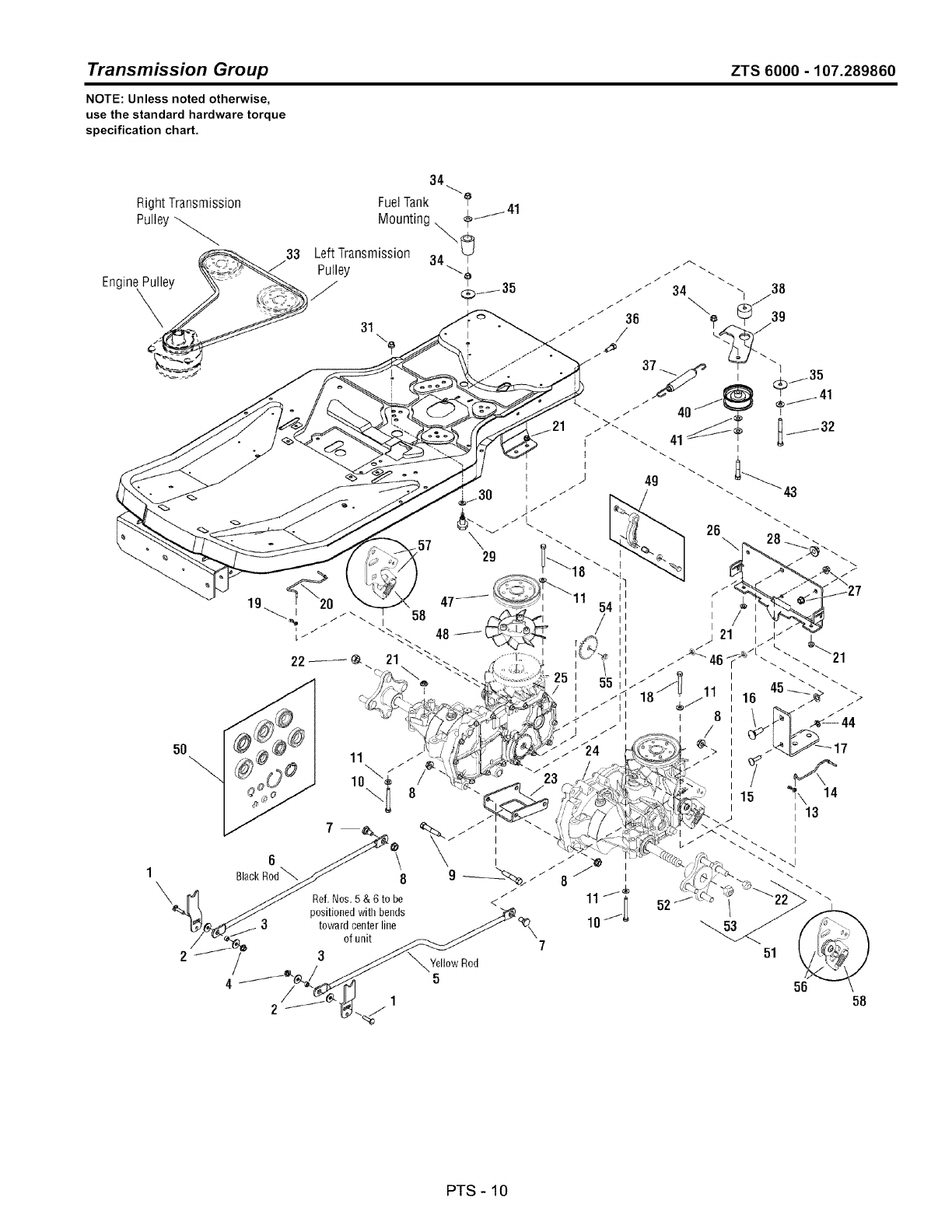
Transmission Group ZTS 6000 -107.289860
NOTE: Unless noted otherwise,
use the standard hardware torque
specification chart.
PTS - 10
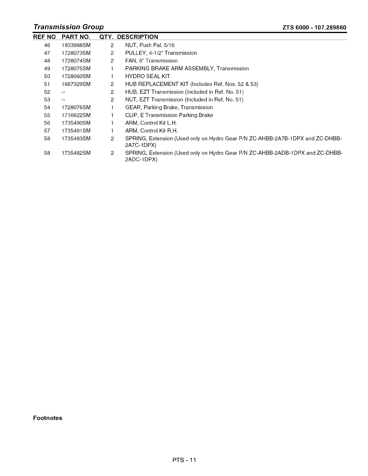
Transmission Group
REF NO PART NO. QTY.
46 1933988SM 2
47 1728073SM 2
48 1728074SM 2
49 1728075SM 1
50 1728060SM 1
51 1687329SM 2
52 -- 2
53 -- 2
54 1728076SM 1
55 1716622SM 1
56 1735490SM 1
57 1735491SM 1
58 1735483SM 2
58 1735482SM
ZTS 6000 -107.289860
DESCRIPTION
NUT, Push Pal, 5/16
PULLEY, 4-1/2" Transmission
FAN, 6" Transmission
PARKING BRAKE ARM ASSEMBLY, Transmission
HYDRO SEAL KIT
HUB REPLACEMENT KIT (Includes Ref. Nos. 52 & 53)
HUB, EZT Transmission (Included in Ref. No. 51)
NUT, EZT Transmission (Included in Ref. No. 51)
GEAR, Parking Brake, Transmission
CLIP, E Transmission Parking Brake
ARM, Control Kit L.H.
ARM, Control Kit R.H.
SPRING, Extension (Used only on Hydro Gear P/N ZC-AHBB-2A7B-1DPX and ZC-DHBB-
2A7C-1DPX)
SPRING, Extension (Used only on Hydro Gear P/N ZC-AHBB-2ADB-1DPX and ZC-DHBB-
2ADC-1 DPX)
Footnotes
PTS - 11
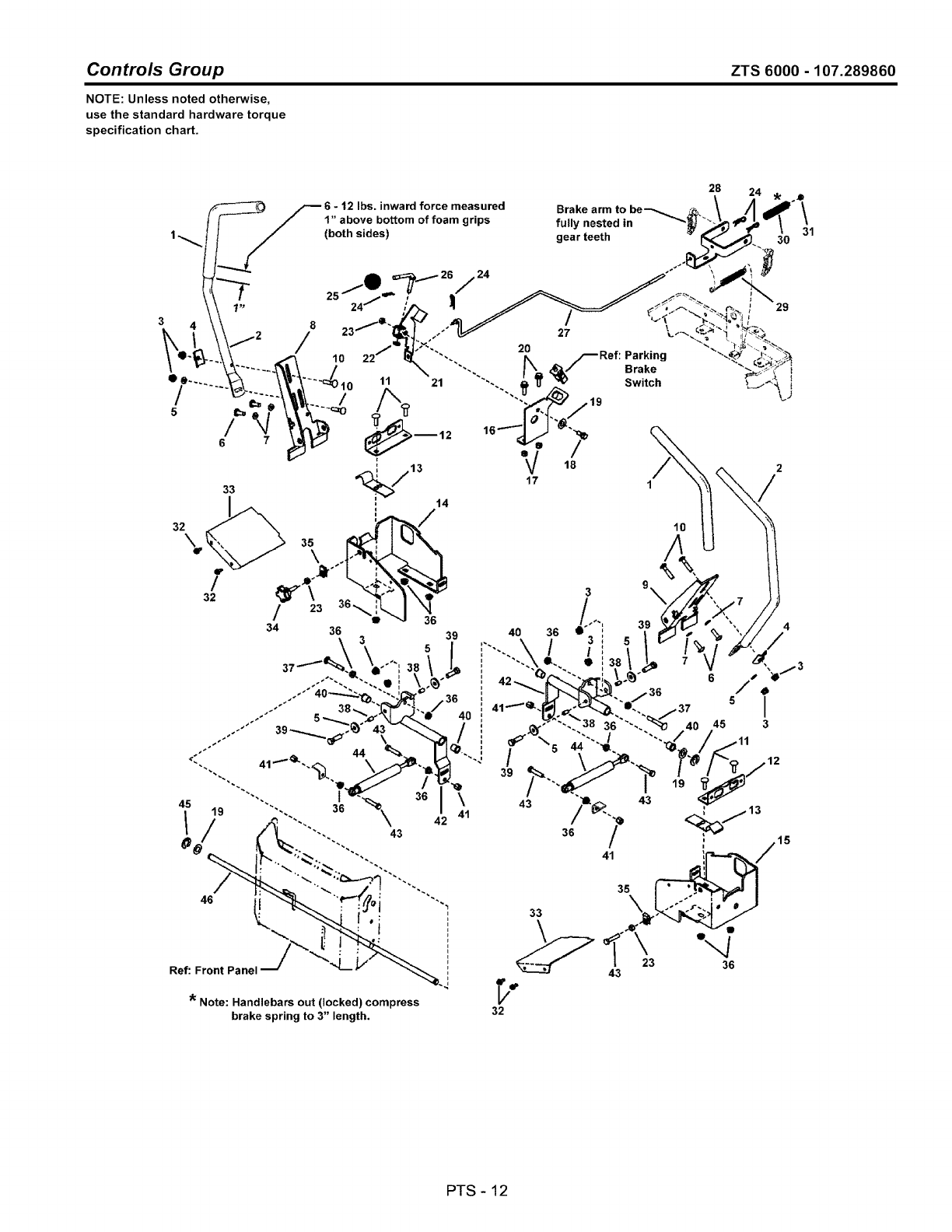
Controls Group ZTS 6000 - 107.289860
NOTE: Unless noted otherwise,
use the standard hardware torque
specification chart.
28
33
32\
f
/
32
12 Ibs. inward force measured
1" above bottom of foam grips
24
21
)_12
44
36 \
41
\42
43
Ref: Front Panel
* Note: Handlebars out (locked) compress
brake spring to 3" length.
F
F
)
Brake arm to be'--.
fully nested in
gear teeth
Parking
Brake
Switch
29
31
10
33
32
PTS - 12

Controls Group
REF NO PART NO.
1 1726410SM 2
2 1727796ASM 2
3 1960686SM 10
4 1720452SM 2
5 1919381SM 6
6 1960086SM 4
7 1917356SM 4
8 1727926ASM 1
9 1727927ASM 1
10 1931338SM 4
11 1931335SM 4
12 1727663ASM 2
13 1727919SM 2
14 1728010ASM 1
15 1728009ASM 1
16 7300992AYP 1
17 7091298SM 3
18 7015761YP 1
19 1960027SM 3
20 7091591SM 2
21 7300993AYP 1
22 7090188SM 1
23 1920161SM 7
24 1722460SM 4
25 7072403YP 1
26 7102567YP 1
27 7102551YP 1
28 1727814ASM 1
29 1709314SM 1
30 1729277SM 1
31 1960694SM 1
32 1925003SM 4
33 1727933ASM 2
34 1726839SM 1
35 1960717SM 2
36 1931277SM 8
37 1960723SM 2
38 1666697SM 4
39 1921977SM 5
40 1715025SM 4
41 1919438SM 4
42 1727603ASM 2
43 1921221SM 4
QTY. DESCRIPTION
GRIP, Foam Handle Bar
TUBE, Handle
NUT, 5/16-18 Hex Flange Nyloc
CLAMP, Tube, Saddle
WASHER, 5/16" Flat (.341 I.D. x 1.00 O.D. x .13 Thick) Black
SCREW, 5/16-18 x 7/8" Truss Head Torx, Black
LOCKWASHER, Spring 5/16", Black
BRACKET, Tube Mount LH
BRACKET, Tube Mount RH
BOLT, 5/16-18 x 1-3/4" Round Head Short Square Neck, GR5
BOLT, 5/16-18 x 1" Round Head Short Square Neck, GR5, Zinc
BRACKET, "L" Switch
CLIP, Brake
BRACKET, RH Mounting Handle Pivot
BRACKET, LH Mounting Handle Pivot, Black
BRACKET, Brake Pivot- ZT
NUT, 5/16-18-3B Hex Nyloc
SHOULDER BOLT, 5/16-18
WASHER, 1/2" Flat
BOLT, 5/16-18 x 1" Hex Flange Lock YZ
ARM, Brake Pivot- ZT
WASHER, .34 x .69 x .08 Flat
NUT, 5/16-18 Hex Jam, Black
HAIR PIN
KNOB, w/5/16-18 NILN (Brake/Clutch)
ROD, Park Brake- ZT (5/16-18 thread)
ROD, Manual Parking Brake (1/4-20 threads)
BRACKET, Dual Brake
SPRING, Extension
SPRING, Compression
NUT, 1/4-20 Hex Flange Nyloc, Black
SCREW, 1/4-20 x 1/2" Hex Washer Head Screw Black (Taptite)
COVER, Lower Handle
KNOB, 5/16-18 x 1-1/4" Extension Thread
NUT, 5/16-18 Speed (Lug Type .050/.200, Black)
NUT, 5/16-18 Hex Flange Lock, Small - Black
BOLT, 5/16-18 x 2-1/4" Round Head Square Neck, GR5, Black
SPACER, Powdered Metal
SCREW, 5/16-18 x 1-1/4" Hex Head Cap, GR5, Black
BUSHING
NUT, 5/16-18 Hex Lock Esna Light
WELDMENT, Pivot Control
SCREW, 5/16-18 x 1-1/2" Hex Head Cap, GR5, Black
ZTS 6000 -107.289860
Footnotes
PTS - 13
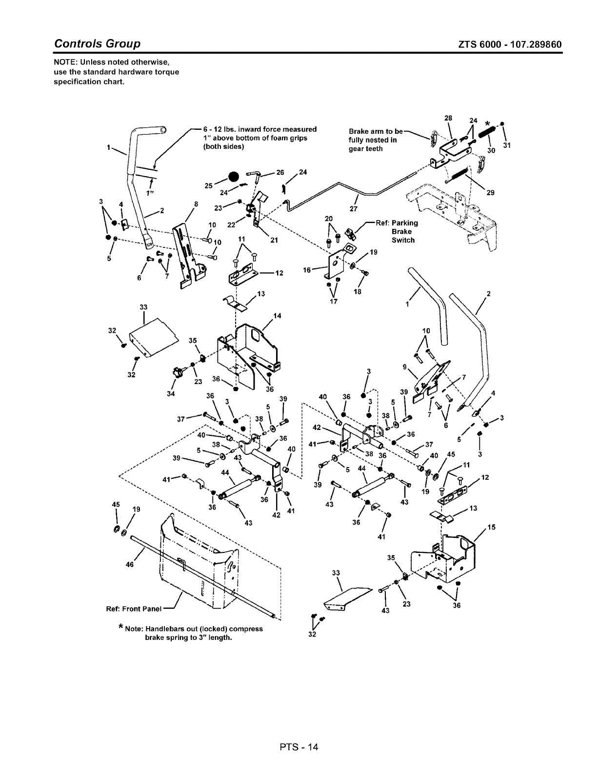
Controls Group ZTS 6000 - 107.289860
NOTE: Unless noted otherwise,
use the standard hardware torque
specification chart.
28
33
32\
f
/
32
12 Ibs. inward force measured
1" above bottom of foam grips
24
21
)_12
44
36 \
41
\42
43
Ref: Front Panel
* Note: Handlebars out (locked) compress
brake spring to 3" length.
F
F
)
Brake arm to be'--.
fully nested in
gear teeth
Parking
Brake
Switch
29
31
10
33
32
PTS - 14

Controls Group
REF NO PART NO. QTY.
44 1727918SM 2
45 1703805SM 2
46 1725927SM 1
DESCRIPTION
SHOCK ABSORBER
RING, Klipring Extension (for .500 Dia. Shaft)
SHAFT, Cross
ZTS 6000 -107.289860
Footnotes
PTS - 15
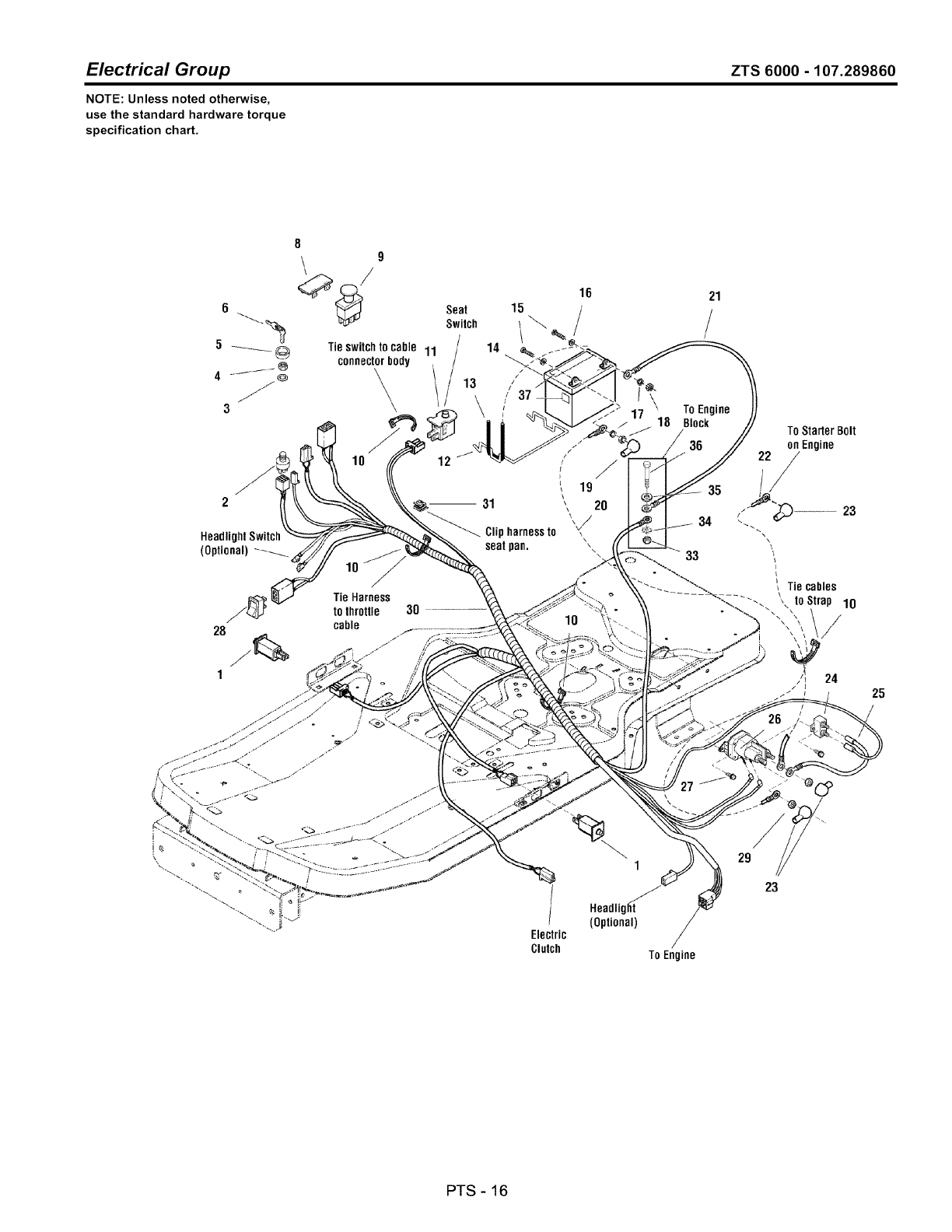
Electrical Group ZTS 6000 - 107.289860
NOTE: Unless noted otherwise,
use the standard hardware torque
specification chart.
89
'/
Tie switchto cable 11
connectorbody
\\\
HeadlighlSwitct
(Optional)
lO
28
1
Tie Harness
to throttle
cable
I-
3O
Seat
Switch
/
/
\
m31
Clipharnessto
seatpan.
16
/
!
!
t
i 19
\\
x\\_/
10
/
f
1
Electric
Clutch
1
Headligl{t
(Optional)
21
/
\To Engine
17 "
18 Block To StarterBolt
on Engine
34 _ .............23
\
\
33
r
_ _\ _ Tie cables
\-._. _ _, loStrop 10
,/
27
29
23
To Engine
25
PTS - 16

Electrical Group
REF NO PART NO.
1 7022886YP
2 1686734SM
3 1960547SM
4 1717549SM
5 1717550SM
6 1717163SM
8 1722611SM
9 1722887SM
10 1701011SM
11 7023354YP
12 1667805SM
13 1665872SM
14 1685215SM
15 2823341SM
16 2821319SM
17 2816964SM
18 2816622SM
19 1677296SM
20 1716549SM
21 1713163SM
22 1727668SM
23 1724588SM
24 1665238SM
25 1665237SM
26 7075622SM
27 1925003SM
28 1734141SM
29 2860750SM
30 7103103YP
31 2172434SM
33 1931277SM
34 2820427SM
35 1919326SM
36 1921978SM
37 1734375SM
QTY.
2
1
1
1
1
2
1
1
4
1
1
1
1
2
2
2
2
1
1
1
1
3
1
1
1
2
1
2
1
1
1
1
1
1
1
ZTS 6000 - 107.289860
DESCRIPTION
SWITCH, Push Button
SWITCH ASSEMBLY, Ignition, 5/8-32 6 Pin Indak (Includes Ref. Nos. 20, 21,26, & 37)
LOCKWASHER, Internal Tooth, 5/8 Thin
NUT, Hex Flange, 5/8-32 IGN SW Die Cast
COVER, Ignition Switch
KEYS (Set of Two)
PLUG, Hole
SWITCH, PTO Push/Pull Symbols
TIE, Self Locking, .184 WD 7.31 LG
SWITCH, Push Button
BRACE, Battery, .19 DIA Wire
STRAP, Black Rubber,. 19 SQ 7.88 OD Battery
BATTERY, 12 Volt 6 Cell 340CCA
CAPSCREW, Hex Head, 1/4-20 x 3/4, G5
WASHER, 1/4, .27 ID x .62 OD x .05 THK
LOCKWASHER, Spring, 1/4
NUT, Hex, 1/4-20 NC-2B
BOOT, Insulator, Red PVC Warning
CABLE, # 6 x 10 LG, Red Two-Ring Terminals
CABLE, # 6 X 26 LG, Two-Ring Terminals
CABLE, # 6 x 15 LG, Two-Ring Terminals
COVER, Terminal Red PVC
BREAKER, Circuit, 12 Volt 20 AMP
WIRE, 12 Gauge, 7.9 LG
SOLENOID, Two Terminals, Trombetta
SCREW, Hex Washer Head Taptite, 1/4-20 x 1/2
SWITCH, Electric Height of Cut
NUT, Hex Keps, 5/16-24
HARNESS, Wiring
CABLE, Clip
NUT, Hex Whiz Lock Flange, 5/16-18
LOCKWASHER, External Tooth, 3/8
WASHER, 5/16, .34 ID x 3/40D x .06 THK
CAPSCREW, Hex Head, 5/16-18 x 2, G5
DECAL, Diehard
Footnotes
PTS - 17
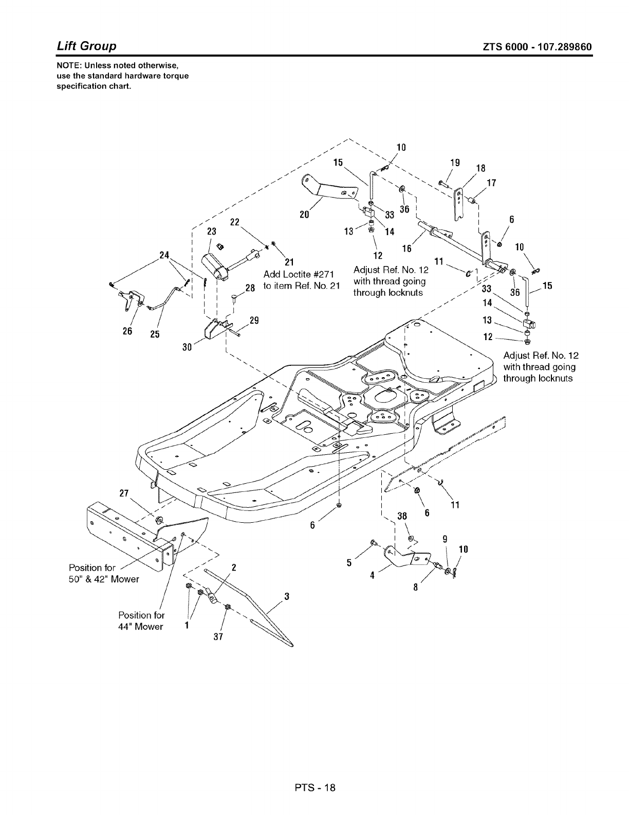
Lift Group ZTS 6000 - 107.289860
NOTE: Unless noted otherwise,
use the standard hardware torque
specification chart.
24
/ /
26 25
30
21
Add Loctite #271
to item Ref. No. 21
19 18
17
L
14 _-
\ 16
]1
Adjust Ref. No. 12 _¢..
with thread going /
through Iocknuts /"
f
/"
J
Adjust Ref. No. 12
with thread going
through Iocknuts
27
>
Posttion for J _ / /
I
50"& 42" Mower
/
Position for
44" Mower 37
5
4
I
I
I38 6
,\
t_> 9
11
10
!
PTS - 18

Lift Group ZTS 6000 - 107.289860
REF NO
1
2
3
4
5
6
8
9
10
11
12
13
14
15
16
17
18
19
20
21
22
23
24
25
26
27
28
29
30
33
36
37
38
PART NO.
1922007SM
1734042SM
1733381SM
1733535ASM
009x67MA
7091575SM
094067MA
1960170SM
1960074SM
1704420SM
1960687SM
1666294SM
1731894SM
1734217SM
1733356ASM
1673796SM
1734336ASM
1931337SM
1733536ASM
1960757SM
1921319SM
1733513SM
1722460SM
1733572SM
1733454SM
1930644SM
1931335SM
1668344SM
1733533ASM
1916950SM
1924940SM
1918213SM
1930645SM
QTY.
4
2
1
1
2
5
2
2
4
2
2
2
2
2
1
1
1
1
1
1
1
1
3
1
1
2
1
1
1
2
2
2
2
DESCRIPTION
NUT, Hex Jam, 7/16-14
TRUNNION
ROD, Bail
ARM, Mower Lift L.H.
BOLT, Shoulder
NUT, Hex Flange Whiz Lock, 5/16-18
PIN, Threaded Shoulder
WASHER, 1/2
CLIP, Hairpin
RING, Klipring, 5/8
NUT, Hex Flange Nylock, 3/8-16 ESNA
SPACER, Powdered Metal
TRUNNION, Powdered Metal
ROD, Mower Lift, 3.5 LG Thread
LIFT SHAFT ASSEMBLY
SPACER, Powdered Metal
ARM, Lift Trunnion
CARRIAGE BOLT, 5/16-18 x 1-1/2, G5
ARM, Mower Lift R.H.
NUT, Hex, 1/4-20 L.H. Thread
WASHER, 1/4
MOTOR, Mini Actuator
CLIP, Hairpin
ROD, Height of Cut Indicator
INDICATOR, Height of Cut
NUT, Hex Two-Way Lock, 1/2-13
CARRIAGE BOLT, 5/16-18 x 1, G5
PIN, Shear
BRACKET, Electric Motor Mount
NUT, Hex, 3/8-16
WASHER, 3/8
NUT, Hex 7/16-14
NUT, Hex Flange Two-Way Lock, 3/8-16
Footnotes
PTS - 19
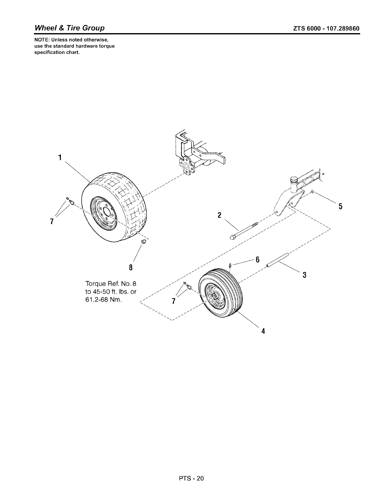
Wheel & Tire Group ZTS 6000 -107.289860
NOTE: Unless noted otherwise,
use the standard hardware torque
specification chart.
7
1
/
/
8
Torque Ref. No. 8
to 45-50 ft. Ibs. or
61.2-68 Nm.
.7
! tl/k<.<.<.
>¢_'J'
f
t
i
f
f
i
J .i i /.
5
PTS - 20

Wheel & Tire Group
REF NO PART NO. QTY.
1 1726383SM 2
2 7091772SM 2
3 1724841SM 2
4 1734013SM 2
5 7090839SM 2
6 2812808SM 2
7 2172353SM 2
8 2177725SM 8
ZTS 6000 -107.289860
DESCRIPTION
WHEEL & TIRE ASSEMBLY, 18 x 8-1/2-8
CAPSCREW, Hex Head
TUBE, Caster Wheel Spacer
WHEEL & TIRE ASSEMBLY, 11 x 4-5
NUT, Hex Center Lock
FITTING, Lube
VALVE STEM & CAP
NUT, Hex Lug, 7/16-20
Footnotes
PTS - 21
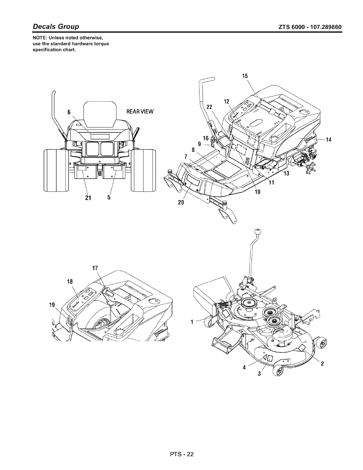
Decals Group ZTS 6000 - 107.289860
NOTE: Unless noted otherwise,
use the standard hardware torque
specification chart.
15
6
f
I REARVIEW
,L...._
21 5 2O
16
g
12
\
I0
11
13
14
Ig\
18
\
17
PTS - 22

Decals Group ZTS 6000 - 107.289860
REF NO PART NO.
1 1704277SM
2 1704276SM
3 1731924SM
4 *
5 7103145YP
6 1734147SM
7 7102575YP
8 7102574YP
9 1726638SM
10 7103172YP
11 1734335SM
12 1734140SM
13 1734270SM
14 7103067YP
15 7103068YP
16 7102576YP
17 1726631SM
18 7103082YP
19 1734276SM
20 7103146YP
21 1734672SM
22 7102578YP
-- 1717163SM
-- 7103069
QTY.
1
1
1
1
1
1
1
1
1
1
1
1
1
1
1
1
1
1
1
1
1
1
1
1
DESCRIPTION
DECAL Danger Do No Operate without Deflector
DECAL Danger Do Not Put Hands/Feet in Mower
DECAL 42" 2006 Silver/Black
DECAL OPEl Certified ANSI B71.12003 Gold
DECAL Transmission Release Instructions
DECAL Craftsman Logo (Large)
DECAL Operator Instructions Front
DECAL Operator Intructions Bottom
DECAL Tracking Adjustment ZT 7000
DECAL ZTS 7500, 20/42
DECAL Height of Cut
DECAL Belt & Blade
DECAL Handle Control L.H. ZTS 6000
DECAL Seat Deck L.H. Craftsman ZTS
DECAL Seat Deck R.H. Craftsman ZTS
DECAL Handle Control R.H. ZTS 7500
DECAL Do Not Remove Foam Around Engine
DECAL Instrument Panel ZTS 6000
DECAL Height of Cut
DECAL CRAFTSMAN Logo (Small)
DECAL CAUTION, Cut Hazard
DECAL ZT PARKING BRAKE
KEY, Ignition Indak Set of Two (Not Shown)
LITERATURE PACK, SEARS ZTS 6000 21/42 (Not Shown)
Footnotes
Note * Not a service part.
PTS - 23
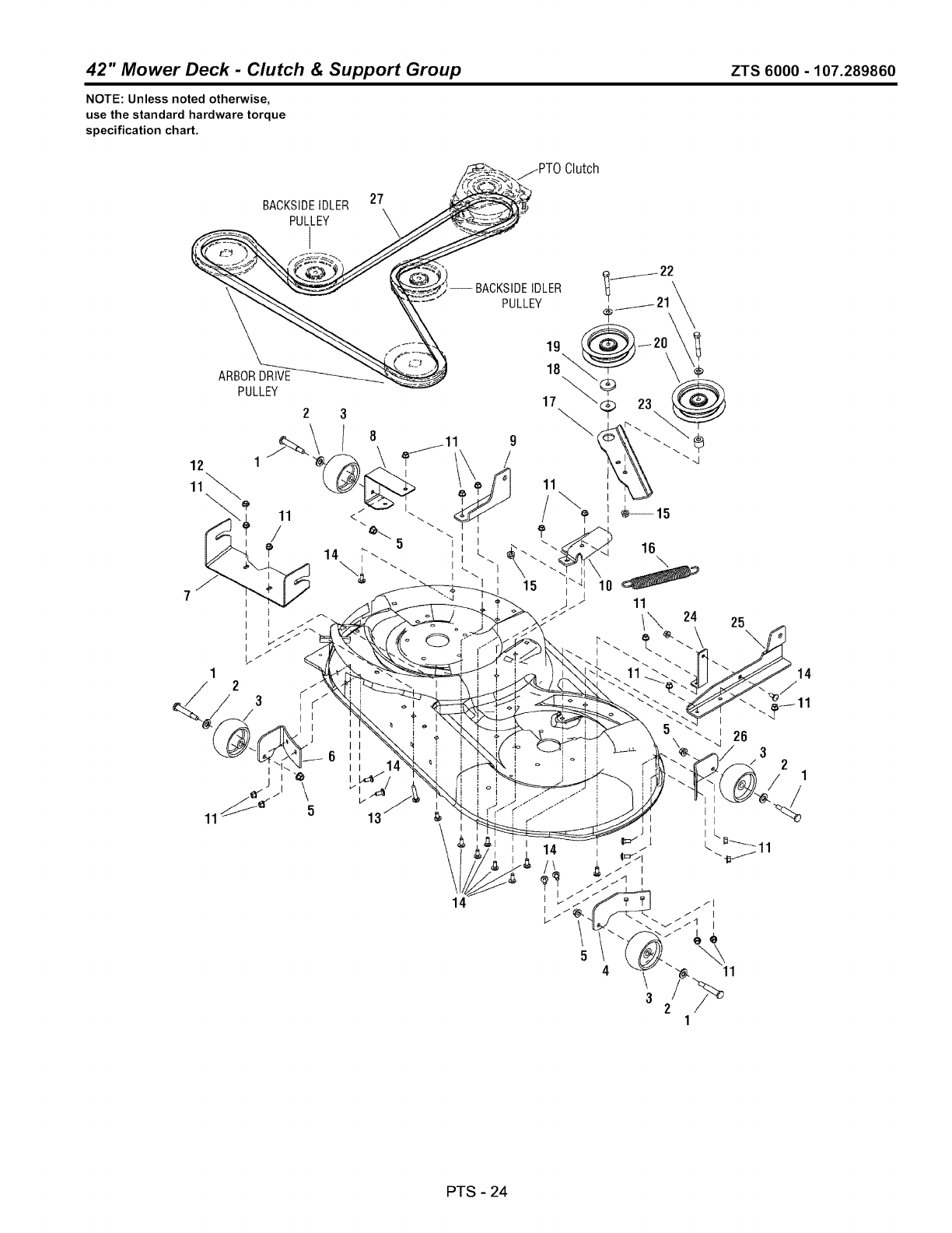
42" Mower Deck -Clutch & Support Group ZTS 6000- 107.289860
NOTE: Unless noted otherwise,
use the standard hardware torque
specification chart.
BACKSIDEIDLER 27
PULLEY
-- BACKSIDEIDLER
PULLEY
ARBOR DRIVE
PULLEY
13 $
14
Clutch
19
18_
14
16
11
1"_ 24 25
PTS - 24

42" Mower Deck -Clutch & Support Group
REF NO
1
2
3
4
5
6
7
8
9
lO
11
12
13
14
15
16
17
18
19
2o
21
22
23
24
25
26
27
27
PART NO.
2108765SM
1960170SM
1714760SM
1732258ASM
1960687SM
1734344ASM
1733578ASM
1734185ASM
1733576ASM
1734242ASM
1931277SM
1935048SM
1931338SM
1931333SM
1931211SM
1733844SM
1734243ASM
1714255SM
1960534SM
1732360SM
1924940SM
1922130SM
1667812SM
1733577ASM
1733575ASM
1731403ASM
1732966SM
1734048SM
QTY.
4
4
4
1
4
DESCRIPTION
BOLT, Shoulder (Gauge Wheel) 3/8-16 x 2.781 x 3/4
WASHER, .51 ID x 10D x 1/10 THK
GAUGE WHEEL
BRACKET, Gauge Wheel L.H. Front
NUT, Hex Flange, 3/8-16 ESNA
2 BRACKET, Gauge Wheel R.H. Front
1 HITCH, Mower Front
1 BRACKET, Gauge Wheel R.H. Rear
1 SUPPORT, Mower Rear R.H.
1 BRACKET, Fixed Idler
17 NUT, Hex Flange Whiz Lock, 5/16-18
1 NUT, Hex Two-Way Lock, 5/16-18
1 CARRIAGE BOLT, 5/16-18 x 1-3/4, G5
16 CARRIAGE BOLT, 5/16-18 x 3/4, G5
2 NUT, Hex Flange Whiz Lock, 3/8-16
1 SPRING, Extension
1 ARM, Idler
1 SPACER, Powdered Metal
1 WASHER, 3/8, .41 IDx 1-1/20D x 1/4 THK
2 PULLEY, Idler, 40D x .378 ID x 1
2 WASHER, 3/8, .41 ID x .87 OD x .08 THK
2 CAPSCREW, Hex Head, 3/8-16 x 2-1/4, G5
1 SPACER
1 BRACE, Mower Support
1 SUPPORT, Mower Rear L.H.
1 SUPPORT, Gauge Wheel L.H. Rear
1 V-BELT, A-Wedge
1 V-BELT, A-Wedge (Used on Export Models)
ZTS 6000 -107.289860
Footnotes
PTS - 25
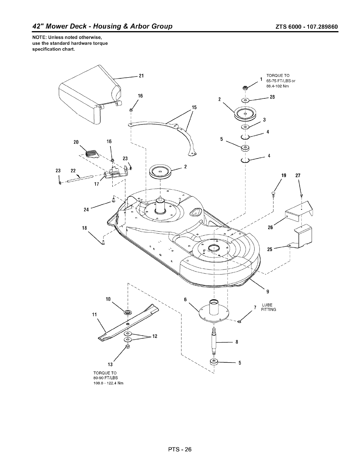
42" Mower Deck -Housing & Arbor Group ZTS 6000 -107.289860
NOTE: Unless noted otherwise,
use the standard hardware torque
specification chart.
24
18
21
16
/15
TORQUE TO
1 65-75 FT/LBS or
88.4-102 Nm
I
i 4
10
13
TORQUE TO
80-90 FT/LBS
108.8 - 122.4 Nm
L
_8
9
LUBE
7 FITTING
PTS - 26

-Housing & Arbor Group ZTS 6000 -107.289860
42" Mower Deck
REF NO PART NO. QTY.
1 1960576SM 2
2 1732354SM 2
3 7072440SM 2
4 7012491SM 4
5 2108202SM 4
6 1731372BMYP 2
7 1704314SM 2
8 7072537SM 2
9 1730100BNYP 1
10 1731917SM 2
11 1731898ASM 2
12 7024467SM 4
13 7091633SM 2
15 721083BMYP 2
16 1960686SM 6
17 721369BMYP 1
18 1931333SM 5
19 1923683SM 10
20 0166x4MA 1
21 094707MA 1
22 094957ZMA 1
23 1960093SM 2
24 1921333SM 1
25 1732282BMYP 1
26 1732832BMYP 1
27 1925003SM 2
28 7016440SM 2
DESCRIPTION
NUT, Hex Nylock, 5/8
PULLEY, Drive, 5-1/2
SPACER, Pulley
RING, Retaining, 1-3/4
BEARING, Spindle
TUBE & PLATE ASSEMBLY, Spindle
LUBE, Fitting, 1/4
SHAFT, Spindle
HOUSING, 42" Sears Craftsman Red
WASHER, Spindle Blade, Powdered Metal
BLADE, Mower 42"
WASHER, Belleville
NUT, Hex, 9/16
PLATE, Rear
NUT, Hex Flange, 5/16-18 ESNA
BRACKET, Hinge
CARRIAGE BOLT, 5/16-18 x 3/4, G5
SCREW, Hex Washer Head Taptite, 3/8-16 x 3/4
SPRING, Torsion
DEFLECTOR ASSEMBLY
ROD, Deflector
NUT, Pushpal
CAPSCREW, Hex Head, 5/16-18 x 1, G5
BRACKET, Pulley Cover
COVER, Pulley
SCREW, Hex Washer Head Taptite, 1/4-20 x 1/2
WASHER, Belleville
Footnotes
PTS - 27
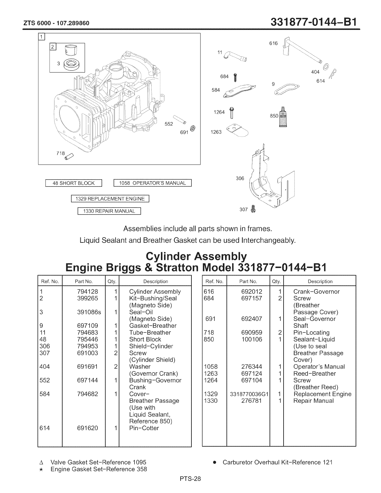
ZTS 6000 - 107.289860
11
\
552 "e
691 @
684]
584
718_
i
48 SHORT BLOCK ] ] 1058 OPERATOR'S MANUAL ]
[1329 REPLACEMENT ENGINE ]
]1330 REPAIR MANUAL ]
1263
331877-0144-B1
1264
616
f i
if;
307
S{t
404 /_
614
Assemblies include all parts shown in frames.
Liquid Sealant and Breather Gasket can be used Interchangeably.
Cylinder Assembly
Engine Briggs & Stratton
Ref. No. Part No. Qty. Description
1 794128 1 Cylinder Assembly
2 399265 1 Kit-Bushing/Seal
(Magneto Side)
3 391086s 1 Seal-Oil
(Magneto Side)
9 697109 1 Gasket-Breather
11 794683 1 Tube-Breather
48 795446 1 Short Block
306 794953 1 Shield-Cylinder
307 691003 2 Screw
(Cylinder Shield)
404 691691 2 Washer
(Governor Crank)
552 697144 1 Bushing-Governor
Crank
584 794682 1 Cover-
Breather Passage
(Use with
Liquid Sealant,
Reference 850)
614 691620 1 Pin-Cotter
Model 331877-0144-B1
Ref. No.
616
684
691
718
85O
1058
1263
1264
1329
1330
Part No. Qty. Description
692012 1 Crank-Governor
697157 2 Screw
(Breather
Passage Cover)
692407 1 Seal-Governor
Shaft
690959 2 Pin-Locating
100106 1 Sealant-Liquid
(Use to seal
Breather Passage
Cover)
276344 1 Operator's Manual
697124 1 Reed-Breather
697104 1 Screw
(Breather Reed)
3318770036G1 1 Replacement Engine
276781 1 Repair Manual
A Valve Gasket Set-Reference 1095
Engine Gasket Set-Reference 358
PTS-28
• Carburetor Overhaul Kit-Reference 121
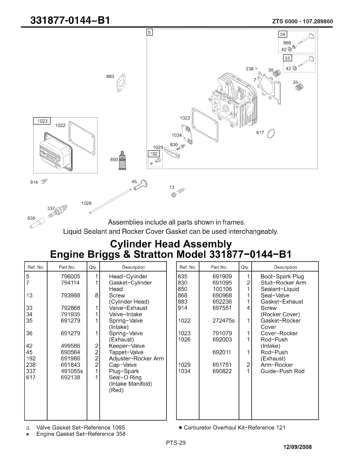
331877-0144-B1
1022
883
J
1022
238 O
617 _!)
914 _
63t_',
1026 ___
Assemblies include all parts shown in frames.
Liquid Sealant and Rocker Cover Gasket can be used interchangeably.
Cylinder Head Assembly
Engine Briggs & Stratton Model 331877-0144-B1
Ref. No. Part No. Qty. Description
5 796005 1 Head-Cylinder
7 794114 1 Gasket-Cylinder
Head
13 793988 8 Screw
(Cylinder Head)
33 792868 1 Valve-Exhaust
34 791935 1 Valve-Intake
35 691279 1 Spring-Valve
(Intake)
36 691279 1 Spring-Valve
(Exhaust)
42 499586 2 Keeper-Valve
45 690564 2 Tappet-Valve
192 691986 2 Adjuster-Rocker Arm
238 691843 2 Cap-Valve
337 491055s 1 Plug-Spark
617 692138 1 SeaI-O Ring
(Intake Manifold)
(Red)
Ref. No. Part No. Qty.
635 691909 1
830 691095 2
850 100106 1
868 690968 1
883 692236 1
914 697551 4
1022 272475s
1023 791079
1026 692003
692011
1029 691751
1034 690822
1
1
2
1
Description
Boot-Spark Plug
Stud-Rocker Arm
Sealant-Liquid
Seal-Valve
Gasket-Exhaust
Screw
(Rocker Cover)
Gasket-Rocker
Cover
Cover-Rocker
Rod-Push
(Intake)
Rod-Push
(Exhaust)
Arm-Rocker
Guide-Push Rod
A Valve Gasket Set-Reference 1095
Engine Gasket Set-Reference 358
• Carburetor Overhaul Kit-Reference 121
PTS-29 12/09/2008

ZTS8000-107.289860 331 877"01 44-B1
27
2_
1044
161
146
741
1270
759
24 i_i
Assemblies include all parts shown in frames.
Crankshaft, Piston/Ring and Counterweight Assembly
Engine Briggs & Stratton Model 331877-0144-B1
Ref. No.
16
24
25
26
27
28
29
32
Part No. Qty. Description
793410 1 Crankshaft
222698s 1 Key-Flywheel
794124 1 Piston Assembly
(Standard)
794125 1 Piston Assembly
(.020" Oversize)
794126 1 Ring Set
(Standard)
794127 1 Ring Set
(.020" Oversize)
698469 1 Lock-Piston Pin
794143 1 Pin-Piston
794571 1 Rod-Connecting
791118 2 Screw
(Connecting Rod)
Ref. No. Part No. Qty. Description
146 691639 1
741 697128 1
757 793242 2
758 793763 1
759 697392 2
1044 698139 1
1270 793243
Key-Timing
Gear-Timing
Link-Counterweight
Counterweight
Pin-Counterweight
Screw
(Flywheel)
Plug-AVS
Counterweight
A Valve Gasket Set-Reference 1095
Engine Gasket Set-Reference 358
12/09/2008
• Carburetor Overhaul Kit-Reference 121
PTS-30

331877-0144-B1 zTs8000-lo7.28986o
200
12
22 15 _i_
617
54
1O27
943
75o_
51
51A
4_J 45
J
Assemblies include all parts shown in frames.
Engine Sump, Intake Manifold and Camshaft Assembly
Engine Briggs & Stratton Model 331877-0144-B1
Ref. No. Part No. Qty. Description
4 795993
12 69711O
15 690946
20 795387
22 692125
43 691968
45 690564
46 793880
50 690193
51 692137
51A 794312
1
1
1
1
10
1
2
1
1
1
1
Sump-Engine
Gasket-Crankcase
Plug-Oil Drain
Seal-Oil
(PTO Side)
Screw
(Crankcase
Cover/Sump)
Governor/Oil Slinger
Tappet-Valve
Camshaft
Manifold-Intake
Gasket-Intake
Gasket-Intake
Ref. No. Part No. Qty.
54 691148 2
617 692138 1
750 790832
943 690589
965 499613
1017 690770
1024 794644
1027 795890
Description
1
1
1
1
Screw
(Intake Manifold)
SeaI-O Ring
(Intake Manifold)
(Red)
Screw
(Oil Pump Cover)
SeaI-O Ring
(Oil Pump Cover)
Cover-Oil Pump
Screen-Oil Pump
Pump-Oil
Filter-Oil
A Valve Gasket Set-Reference 1095
, Engine Gasket Set-Reference 358
o
PTS-31
Carburetor Overhaul Kit-Reference 121
12/09/2008

zrs8000-lo7.28986o 331 877.-01 44-B1
177 (
525
24O
385
Assemblies include all parts shown in frames.
Dipstick/Tube and Fuel Pump Assembly
Engine Briggs & Stratton Model 331877-0144-B1
Ref. No.
177 691031
187 791805
Part No. Qty. Description
240 691035
385 694476
385A 690297
387 697090
387A 808656
1
1
1
1
1
1
SeaI-O Ring
(Dipstick)
Line-Fuel
(Formed)
(Cut to
Required Length)
Filter-Fuel
Screw
(Fuel Pump)
(Long)
Screw
(Fuel Pump)
(Short)
Pump-Fuel
(Includes Bracket)
Pump-Fuel
Ref. No. Part No. Qty.
523 699908 1
524 691032 1
525 697085 1
601 79185O 6
847 790443 1
918 791851
Description
Dipstick
SeaI-O Ring
(DipstickTube)
Tube-Dipstick
Clamp-Hose
Dipstick/Tube
Assembly
Hose-Vacuum
(Formed)
(Cut to
Required Length)
A Valve Gasket Set-Reference 1095
Engine Gasket Set-Reference 358
12/09/2008
• Carburetor Overhaul Kit-Reference 121
PTS-32
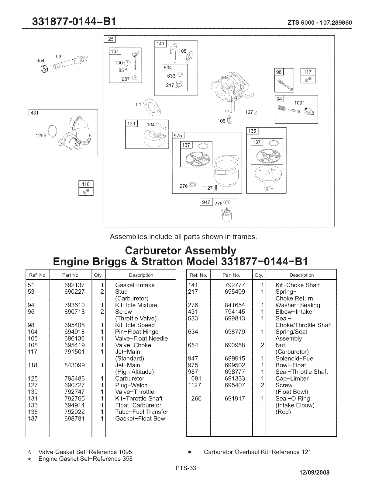
331877"-0144-B1 zrs_ooo-lo7.28988o
654
1266 '4_/"
13o_?)it
95 _ _
987 (_)
51
104 <-_\
\ ...... /
105
127
1091
Assemblies include all parts shown in frames.
Carburetor Assembly
Engine Briggs & Stratton Model 331877-0144-B1
Ref. No.
51 692137
53 690227
Part No. Qty. Description
94 793610
95 690718
98 695408
104 694918
105 696136
108 695419
117 791501
118 843099
125 795486
127 690727
130 792747
131 792765
133 694914
135 792022
137 698781
1
2
1
2
1
1
1
1
1
1
1
1
1
1
1
1
Gasket-intake
Stud
(Carburetor)
Kit-idle Mixture
Screw
(Throttle Valve)
Kit-idle Speed
Pin-Float Hinge
Valve-Float Needle
Valve-Choke
Jet-Main
(Standard)
Jet-Main
(High Altitude)
Carburetor
Plug-Welch
Valve-Throttle
Kit-Throttle Shaft
Float-Carburetor
Tube-Fuel Transfer
Gasket-Float Bowl
Ref. No. Part No. Qty.
141 792777 1
217 695409 1
276 841654
431 794145
633 699813
634 698779
654 690958
947 699915
975 699502
987 698777
1091 691333
1127 695407
1266 691917
Description
1
1
1
1
1
1
1
2
Kit-Choke Shaft
Spring-
Choke Return
Washer-Sealing
Elbow-intake
Seal-
Choke/Throttle Shaft
Spring/Seal
Assembly
Nut
(Carburetor)
Solenoid-Fuel
Bowl-Float
Seal-Throttle Shaft
Cap-Limiter
Screw
(Float Bowl)
SeaI-O Ring
(intake Elbow)
(Red)
A Valve Gasket Set-Reference 1095
Engine Gasket Set-Reference 358
o
PTS-33
Carburetor Overhaul Kit-Reference 121
12/09/2008

zrs_ooo-lo7.28986o 331877.-0144-B1
222
188
209
_Jf_
216 _
265
267
334 !_ 851
877
1i059 }}
1119
877A _ _:_%
Assemblies include all parts shown in frames.
Governor, Ignition and Alternator Assemblies
Engine Briggs & Stratton Model 331877-0144-B1
Ref. No. Part No. Qty. Description
188 691693 3 Screw
(Control Bracket)
202 691841 1 Link-Mechanical
Governor
209 796260 1 Spring-Governor
(Green)
216 691840 1 Link-Choke
222 694042 1 Bracket-Control
227 691374 1 Lever-Governor
Control
232 691842 1 Spring-Governor
Link
265 691024 1 Clamp-Casing
267 794904 1 Screw
(Casing Clamp)
333 795315 1 Armature-Magneto
334 691061 2 Screw
(Magneto Armature)
356 697089 1 Stop-Wire
474 696457 1 Alternator
501 794360 1 Regulator
Ref. No. Part No. Qty.
505 691251 1
526 697088
562 691119
789 698329
851 692424
877 393537
877A 790544
1059 698516
1119 691183
Description
1
1
1
1
1
1
4
Nut
(Governor
Control Lever)
Screw
(Regulator)
Bolt
(Governor
Control Lever)
Harness-Wiring
Terminal-Spark Plug
Wire/Connector-
Alternator
Wire/Connector-
Alternator
Kit-Screw/Washer
Screw
(Alternator)
A Gasket Set-Reference 1095
Engine Gasket Set-Reference 358
12/09/2008
• Carburetor Overhaul Kit-Reference 121
PTS-34
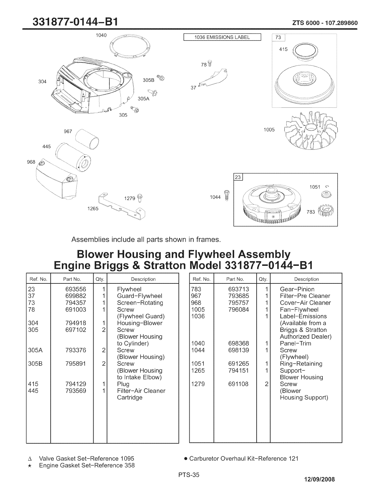
331877.-0144-B1
O4O
445
3O4
3O5
I 1036 EMiSSiONS LABEL I
78_
ZTS 6000-107.289860
73
967 J ............ 1005
37
415
i, i,_
::: ..... 1279 _i_
1265 _. L%, i
udY
1044
1051
783
Assemblies include all parts shown in frames.
Blower Housing and Flywheel Assembly
Engine Briggs & Stratton Model 331877-0144-B1
Ref. No. Part No. Qty. Description
23 693556
37 699882
73 794357
78 691003
304 794918
305 697102
305A 793376
305B 795891
415 794129
445 793569
1
1
1
1
1
2
2
2
1
1
Flywheel
Guard-Flywheel
Screen-Rotating
Screw
(Flywheel Guard)
Housing-Blower
Screw
(Blower Housing
to Cylinder)
Screw
(Blower Housing)
Screw
(Blower Housing
to Intake Elbow)
Plug
Filter-Air Cleaner
Cartridge
Ref. No. Part No. Qty. Description
783 693713
967 793685
968 795757
1005 796084
1036
1040 698368
1044 698139
1051 691265
1265 794151
1279 691108
1
1
1
1
1
1
1
1
1
Gear-Pinion
Filter-Pre Cleaner
Cover-Air Cleaner
Fan-Flywheel
Label-Emissions
(Available from a
Briggs & Stratton
Authorized Dealer)
Panel-Trim
Screw
(Flywheel)
Ring-Retaining
Support-
Blower Housing
Screw
(Blower
Housing Support)
A Valve Gasket Set-Reference 1095
Engine Gasket Set-Reference 358
• Carburetor Overhaul Kit-Reference 121
PTS-35 12/09/2008

zrs8000-lo7.28986o 331 877.-01 44-B1
1051 _'/'_
783 _j_
513
/
801/,:_
8O3
802
310
5O3
729
697_
Assemblies include all parts shown in frames.
Starter Motor Assembly
Engine Briggs & Stratton Model 331877-0144-B1
Ref. No.
309 693551
310 690323
Part No. Qty. Description
503 691532
510 693699
513 692024
544 692034
697 690372
729 691224
783 693713
801 691283
1
2
1
1
1
1
2
1
1
1
Motor-Starter
Bolt
(Starter Motor)
Strap-Starter
Drive-Starter
Drive Clutch
Armature-Starter
Screw
(Drive Cap)
Clip-Wire
Gear-Pinion
Cap-Drive
Ref. No.
802
8O3
Part No. Qty. Description
691286
1051 691265
1090 691293
1
1
1
1
Cap-End
Housing-Starter
(Not Serviced
Separately,
Order Starter
Motor 693551,
Reference 309)
Ring-Retaining
Retainer-Brush
A Valve Gasket Set-Reference 1095
Engine Gasket Set-Reference 358
12/09/2008
e Carburetor Overhaul Kit-Reference 121
PTS-36
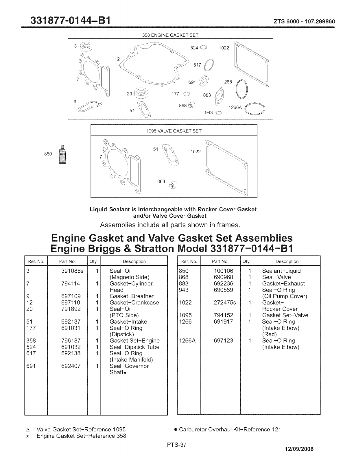
331 877-01 44-B1 zTs8000-lo7.28986o
358 ENGINE GASKET SET
12
617
1022
2O
51
883 1266 0
85O
1095 VALVE GASKET SET
51 1022
Liquid Sealant is Interchangeable with Rocker Cover Gasket
and/or Valve Cover Gasket
Assemblies include all parts shown in frames.
Engine Gasket and Valve Gasket Set Assemblies
Engine Briggs & Stratton Model 331877-0144-B1
Ref. No. Part No. Qty. Description
3 391086s 1 Seal-Oil
(Magneto Side)
7 794114 1 Gasket-Cylinder
Head
9 697109 1 Gasket-Breather
12 697110 1 Gasket-Crankcase
20 791892 1 Seal-Oil
(PTO Side)
51 692137 1 Gasket-Intake
177 691031 1 SeaI-O Ring
(Dipstick)
358 796187 1 Gasket Set-Engine
524 691032 1 Seal-Dipstick Tube
617 692138 1 SeaI-O Ring
(Intake Manifold)
691 692407 1 Seal-Governor
Shaft,
Ref. No. Part No. Qty. Description
850 100106
868 690968
883 692236
943 690589
1022 272475s
1095 794152
1266 691917
1266A 697123
1
1
1
1
1
1
Sealant-Liquid
Seal-Valve
Gasket-Exhaust
SeaI-O Ring
(Oil Pump Cover)
Gasket-
Rocker Cover
Gasket Set-Valve
SeaI-O Ring
(Intake Elbow)
(Red)
SeaI-O Ring
(Intake Elbow)
A Valve Gasket Set-Reference 1095
, Engine Gasket Set-Reference 358
e Carburetor Overhaul Kit-Reference 121
PTS-37 12/09/2008
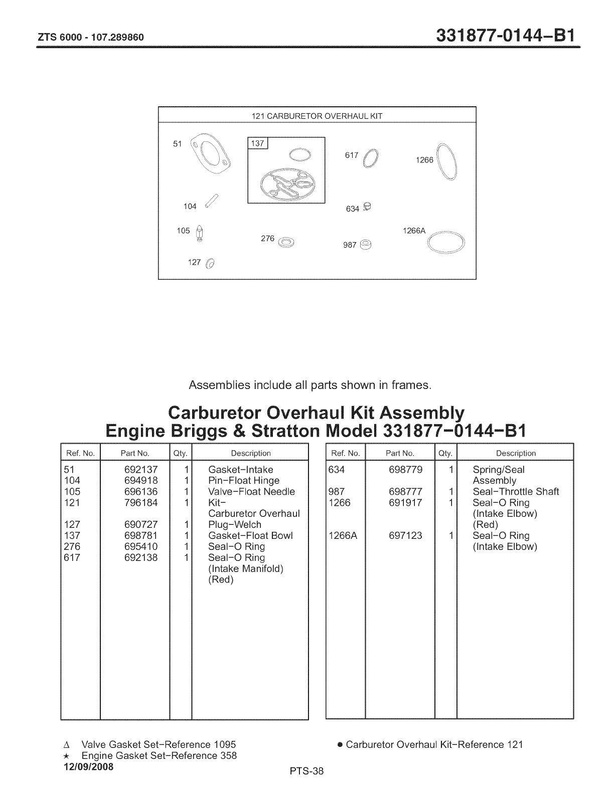
zrs8000-lo7.28986o 331 877.-01 44-B1
121 CARBURETOR OVERHAUL KIT
51
\
\\
104
105
127 _)
I',! i
617
634
276 F_bb
\c:,/ 987 _:_
1266
1266A ................:-.
[, i
Ref. No.
Assemblies include all parts shown in frames.
Carburetor Overhaul Kit Assembly
Engine Briggs & Stratton Model 331877-0144-B1
Part No. Qty. Description
51 692137
104 694918
105 696136
121 796184
127 690727
137 698781
276 695410
617 692138
1
1
1
1
1
1
1
1
Gasket-Intake
Pin-Float Hinge
Valve-Float Needle
Kit-
Carburetor Overhaul
Plug-Welch
Gasket-Float Bowl
SeaI-O Ring
SeaI-O Ring
(Intake Manifold)
(Red)
Ref. No. Part No. Qty.
634 698779 1
987 698777 1
1266 691917 1
1266A 697123
Description
Spring/Seal
Assembly
Seal-Throttle Shaft
SeaI-O Ring
(Intake Elbow)
(Red)
SeaI-O Ring
(Intake Elbow)
A Valve Gasket Set-Reference 1095
Engine Gasket Set-Reference 358
12/09/2008
• Carburetor Overhaul Kit-Reference 121
PTS-38
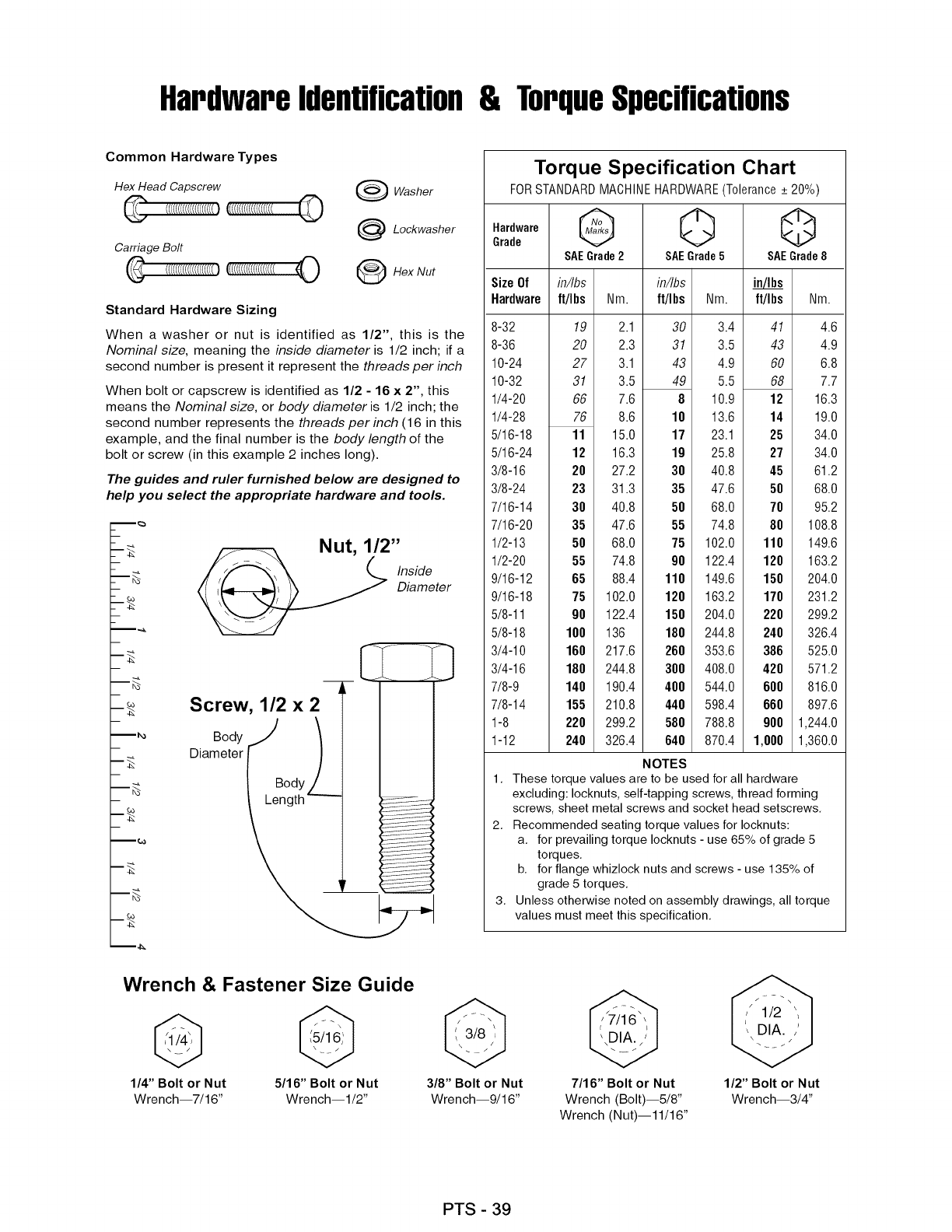
Hardwareidentification& TorqueSpecifications
Common Hardware Types
Hex Head Capscrew
Carriage Belt
€(((((((((((((((((((0
Washer
Leckwasher
_Hex Nut
Standard Hardware Sizing
When a washer or nut is identified as 1/2", this is the
Nominal size, meaning the inside diameter is 1/2 inch; if a
second number is present it represent the threads per inch
When bolt or capscrew is identified as 1/2 - 16 x 2", this
means the Nominal size, or body diameter is 1/2 inch; the
second number represents the threads per inch (16 in this
example, and the final number is the body length of the
bolt or screw (in this example 2 inches long).
The guides and ruler furnished below are designed to
help you select the appropriate hardware and tools.
m_
- _o
m_
m_
m_
mC._
Nut, 1/2"
Inside
Diameter
Screw, 1/2 x 2 _i- I
od,J I
Oi eter( /
i il
Torque Specification Chart
FOR STANDARD MACHINE HARDWARE (Tolerance + 20%)
_raarddeware G 0 Q
SAEGrade2 SAEGrade5 SAEGrade8
Size Of in/Ibs in/Ibs
Hardware ft/I bs ft/I bs Nm.
8-32
8-36
10-24
10-32
1/4-20
1/4-28
5/16-18
5/16-24
3/8-16
3/8-24
7/16-14
7/16-20
1/2-13
1/2-20
9/16-12
9/16-18
5/8-11
5/8-18
3/4-10
3/4-16
7/8-9
7/8-14
1-8
1-12
19
20
27
31
66
76
11
12
20
23
30
35
50
55
65
75
90
100
160
180
140
155
220
240
in/Ibs
Nm. ft/Ibs Nm.
2.1 30 3.4
2.3 31 3.5
3.1 43 4.9
3.5 49 5.5
7.6 810.9
8.6 10 13.6
15.0 17 23.1
16.3 19 25.8
27.2 30 40.8
31.3 35 47.6
40.8 50 68.0
47.6 55 74.8
68.0 75 102.0
74.8 90 122.4
88.4 110 149.6
102.0 120 163.2
122.4 150 204.0
136 180 244.8
217.6 260 353.6
244.8 300 408.0
190.4 400 544.0
210.8 440 598.4
299.2 580 788.8
326.4 640 870.4
41 4.6
43 4.9
60 6.8
68 7.7
12 16.3
14 19.0
25 34.0
27 34.0
45 61.2
50 68.0
70 95.2
80 108.8
110 149.6
120 163.2
150 204.0
170 231.2
220 299.2
240 326.4
386 525.0
420 571.2
600 816.0
660 897.6
900 1,244.0
1,000 1,360.0
NOTES
1. These torque values are to be used for all hardware
excluding: Iocknuts, self-tapping screws, thread forming
screws, sheet metal screws and socket head setscrews.
2. Recommended seating torque values for Iocknuts:
a. for prevailing torque Iocknuts - use 65% of grade 5
torques.
b. for flange whizlock nuts and screws - use 135% of
grade 5 torques.
3. Unless otherwise noted on assembly drawings, all torque
values must meet this specification.
Wrench & Fastener Size Guide
1/4" Bolt or Nut
Wrench--7/16"
5/16" Bolt or Nut
Wrench--I/2"
3/8" Bolt or Nut
Wrench--9/16"
7/16" Bolt or Nut
Wrench (Bolt)--5/8"
Wrench (Nut)--11/16"
1/2" Bolt or Nut
Wrench--3/4"
PTS - 39

PTS-40

PTS- 41

PTS- 42

Repair Protection Agreements
Congratulations on making a smart purchase. Your new
Craftsman® product is designed and manufactured for
years of dependable operation. But like all products, it
may require repair from time to time. That's when having
a Repair Protection Agreement can save you money and
aggravation.
Purchase a Repair Protection Agreement now and
protect yourself from unexpected hassle and expense.
Here's what's included in the Agreement:
Expert service by our 12,000 professional repair
specialists
Unlimited service and no charge for parts and
labor on all covered repairs
E_ Product replacement if your covered product can't
be fixed
Er Discount of 10% from regular price of service and
service-related parts not covered by the agreement;
also, 10% off regular price of preventive maintenance
check
Fast help by phone - phone support from a Sears
technician on products requiring in-home repair, plus
convenient repair scheduling.
Once you purchase the Agreement, a simple phone call
is all that it takes for you to schedule service. You can call
anytime day or night, or schedule a service appointment
online.
Sears has over 12,000 professional repair specialists,
who have access to over 4.5 million quality parts and
accessories. That's the kind of professionalism you can
count on to help prolong the life of your new purchase for
years to come. Purchase your Repair Protection
Agreement today!
Some limitations and exclusions apply. For prices
and additional information call 1-800-827-6655.
Sears Installation Service
For Sears professional installation of home appliances,
garage door openers, water heaters, and other major
home items, in the U.S.A. call 1-800-4-1VlY-HOIVlE®
Acuerdo de Proteccion de Reparaciones
Feficidades por su compra inteligente. Su nuevo
producto de Craftsman® fue disefiado y fabricado para
afios de operaci6n confiable. Pero como todos los
productos, es posible que cada cierto tiempo requiera de
reparaciones. Ahi es donde tener un Acuerdo de
Protecci6n de Reparaciones puede ahorrarle dinero y
contrariedades.
Compre un Acuerdo de Protecci6n de Reparaciones
ahora y protejase usted mismo de molestias y gastos
inesperados.
Aqui esta Io que incluye el Acuerdo:
1_ Servicio experto de nuestros 12,000 especialistas
profesionales en reparaci6n
Servicio ilimitado y sin cargo por las partes y la
Ea"mano de obra en todas las reparaciones cubiertas
Reemplazo del producto si su producto cubierto no
I:;3"puede ser arreglado
Descuento de110% del precio regular de servicio y
I_ partes relacionadas con el servicio no cubierto por el
acuerdo; ademas, de un 10% de descuento del
precio regular por revisiones de mantenimiento
preventivo
Ayuda rapida por telefono - soporte telef6nico de
I:9 tecnicos de Sears sobre productos que requieren
reparaciones a domicilio, ademas de programaci6n
conveniente de reparaci6n.
Una vez que compre el Acuerdo, una simple Ilamada
telef6nica es Io Onico que se necesita para que le
programen el servicio. Usted puede Ilamar a cualquier
hora del dia o de la noche, o programar una cita de
servicio por Internet.
Sears cuenta con mas de 12,000 especialistas
profesionales en reparaci6n, que tienen acceso a mas
de 4.5 millones partes y accesorios de calidad. Ese es el
tipo de profesionalismo con el que usted puede contar
para ayudarle a prolongar la vida de su nueva compra
por muchos afios venideros, iCompre su Acuerdo de
Protecci6n de Reparaciones hoy!
Aplican algunas limitantes y exclusiones. Para
obtener informacion sobre el precio e informacion
adicional Ilame al 1-800-827-6655.
Servicio de Instalacion de Sears
Para obtener informaci6n sobre la instalaci6n profesional
de Sears para electrodomesticos, abridores para
cocheras, calentadores de agua y otros articulos
grandes, en los Estados Unidos Ilame a 1-800.4-1VlY-HOIVlE®
PTS - 43

Your Home
For expert troubleshooting and home solutions advice:
www.managemyhome.com
For repair - in your home - of all major brand appliances,
lawn and garden equipment, or heating and cooling systems,
no matter who made it, no matter who sold it!
For the replacement parts, accessories and
owner's manuals that you need to do-it-yourself.
For Sears professional installation of home appliances
and items like garage door openers and water heaters.
1-800-4-MY-HOME ®(1-800-469-4663)
Call anytime, day or night (U.S.A. and Canada)
www.sears.com www.sears.ca
Our Home
For repair of carry-in items like vacuums, lawn equipment,
and electronics, call anytime for the location of your nearest
Sears Parts & Repair Service Center
1-800-488-1222 (U.S.A.) 1-800-469-4663 (Canada)
.......................................................................................................................................................................................................................www;sears:com www;sears:ca
To purchase aprotection agreement on a product serviced by Sears:
1-800-827-6655 (U.S.A.) 1-800-361-6665 (Canada)
Para pedir servicio de reparaci6n
a domicilio, y para ordenar piezas:
1-888-SU-HOGAR ®
(1-888-784-6427)
Au Canada pour service en fran(_ais:
1-800-LE-FOYER Mc
(1-800-533-6937)
TM
® Registered Trademark /Trademark /SMService Mark of Sears Brands, LLC
® Marca Registrada /TMMarca de F&brica /SM Marca de Servicio de Sears Brands, LLC
MCMarque de commerce /MDMarque depos6e de Sears Brands, LLC © Sears Brands, LLC
