Crane Electronics PO Electronic Torque Wrench User Manual D OptaWrench OptaWrenchb
Crane Electronics Ltd Electronic Torque Wrench D OptaWrench OptaWrenchb
UserManual.wiki
>
Crane Electronics
>
PO User Manual
Users Manual
Navigation menu
Upload a User Manual
Namespaces
Wiki Guide
HTML
PDF
Info
Views
User Manual
Discussion / Help
Navigation
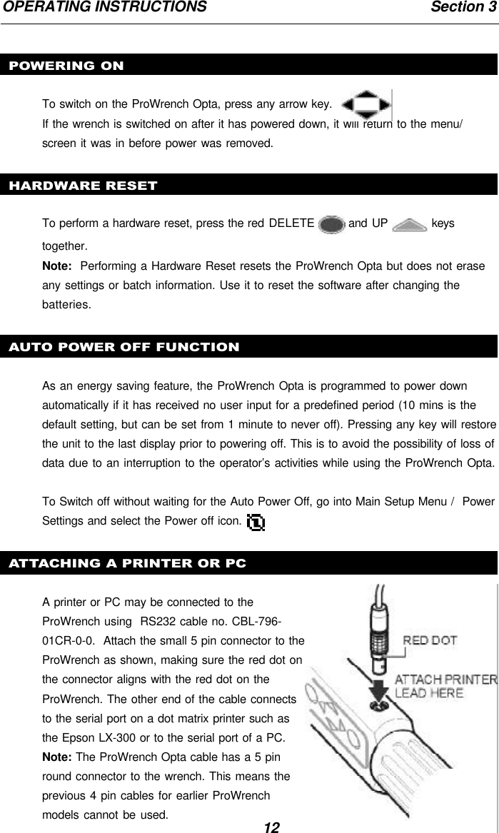
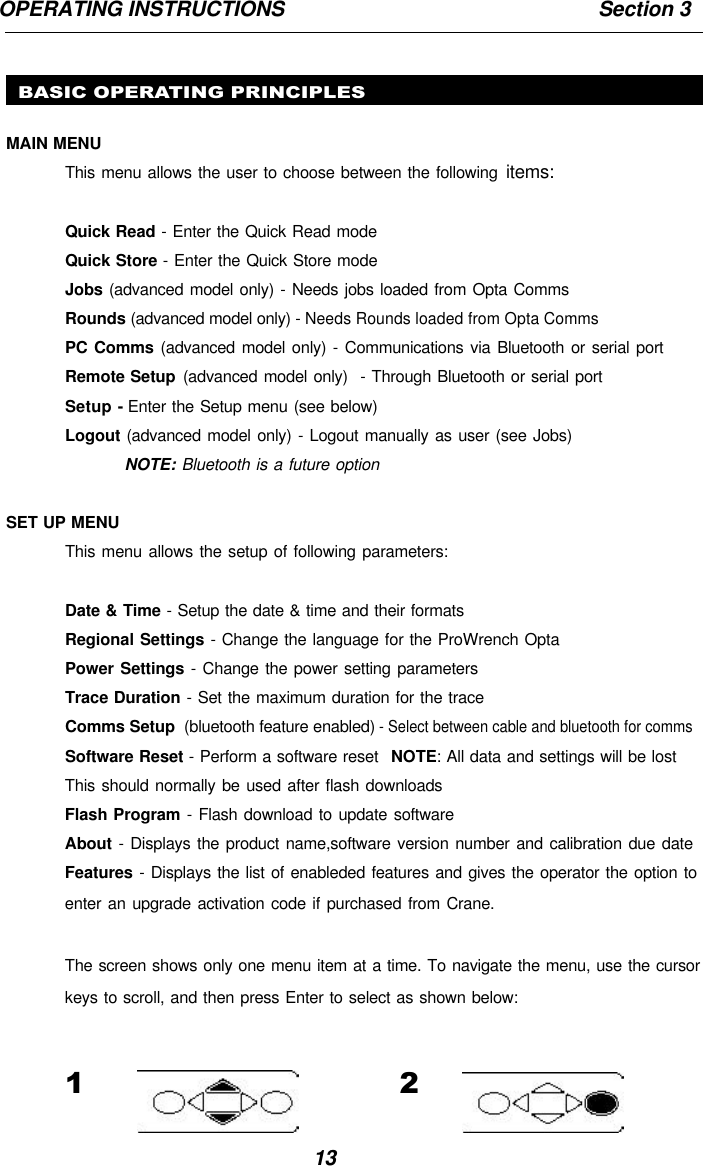
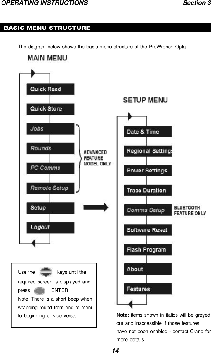
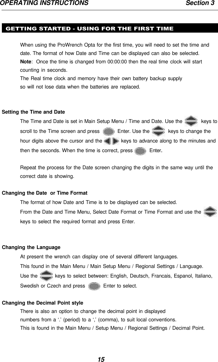
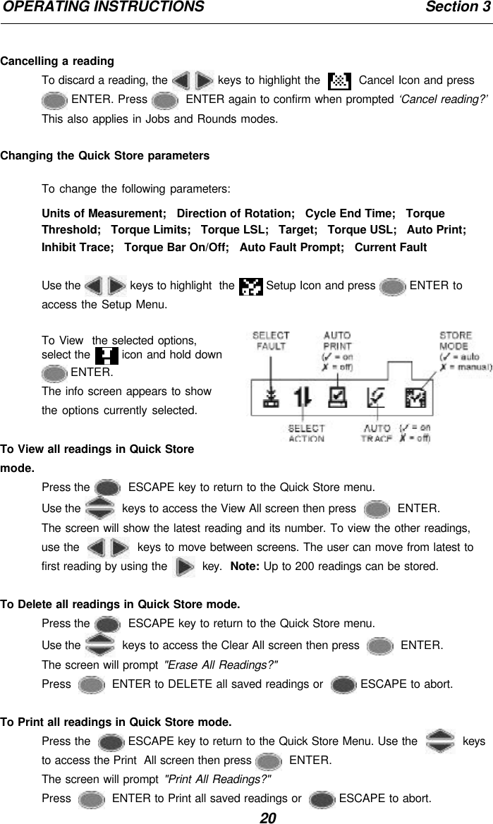
![22OPERATING INSTRUCTIONS Section 3MAIN SETUP MENUUse the Main Setup Menu to change the following:Date and Time (plus date format)Regional Settings (language and decimal point style)Power Settings (battery charge status, battery auto off time, Backlight auto offtime, and battery type [NiMH or alkaline]) See belowTrace Duration (length of trace duration - 5, 10, 20, 30, 40, 50 or 60 secs)Comms Setup (see page 28)Software Reset (see page 28)Flash Program (see page 28)About (shows title screen followed by the software revision)Features - features list and activation code (see page 28)Use the keys to scroll through the menu options (displayed 1 per screen), andpress to edit.Menu options are edited by using the keys to scroll through the options andthen pressing . ENTER.To exit without changing, press ESCAPE.To exit from any screen, press ESCAPE.POWER SETUP MENUUse the Power Setup menu to change the following:Battery Auto Off(1, 2, 5, 10,20, 30, 40 mins, 1 hour, 16 hours or Never Off)Battery Backlight Off(1, 2, 5, 10,20, 30, 40 minutes, 1 hour, 16 hours, Never Off or Always Off)Battery Type(NiMH or Alkaline)Note: it is important to select the correct type for the battery in use. If NiMH have beenselected and Alkaline batteries are installed in the wrench, the wrench will not switchon as it measures the battery voltage as being too low for the type of battery.](https://usermanual.wiki/Crane-Electronics/PO/User-Guide-557946-Page-22.png)