Crane Payment Innovations MEI915WLAN Remote Data Port User Manual Punch
MEI Remote Data Port Punch
Contents
- 1. Manual
- 2. Manual revised
Manual
Technical Support 1-800-345-8172 Remote Data Port Page-1
www.meieasitrax.com Revision G1
Mars Inc. 2003 Printed in USA.
MEI is a trademark of Mars, Inc. Information is subject to change without notice. MEI has made every effort to ensure that the
information in this document is accurate. However, we cannot be held responsible for any errors or omissions.
Remote Data Port
Install Guide
1301 Wilson Drive
West Chester PA 19380
www.meieasitrax.com
Model:
Part No.:
Serial No.:
Voltage: 24-34VDC, 0.5AMPS
Technical Support 1-800-345-8172 Remote Data Port Page-2
www.meieasitrax.com Revision G1
TABLE OF CONTENTS
INTRODUCTION
General Information .............................................................................................. 3
Product Features.................................................................................................... 3
Interfaces Supported ............................................................................................. 3
PRODUCT OVERVIEW
Serial Number......................................................................................................... 4
Configuration.......................................................................................................... 4
Configurable Remote Data Port .......................................................................... 4
MEI Easitrax VT1000........................................................................................... 5
MEI Easitrax Data Pod 200 ................................................................................. 5
Instruction Before Installation ............................................................................. 5
Recommended Tools/Supplies .............................................................................. 5
Required Installation Standard ............................................................................ 5
AUTOMATIC PRODUCT INSTALLATION
AP6000/7000 Series Snack Machine ...............................................................6-8
DIXIE NARCO PRODUCT INSTALLATION
Dixie Single Price Machine..............................................................................9-11
Dixie Narco Motor Cable Chart ........................................................................12
RMI PRODUCT INSTALLATION
RMI 2000 / 8050 Machine ............................................................................ 13-15
Technical Support 1-800-345-8172 Remote Data Port Page-3
www.meieasitrax.com Revision G1
INTRODUCTION
GENERAL INFORMATION
The remote data port lets you add industry-standard DEX data transfer capabilities to machines that
are not audit enabled or add enhanced capabilities to DEX-enabled machines. The remote data port
gathers data on cash transactions and vending cycles, including coin drops, bill insertions and product
sales. This information is stored for later collection.
The remote data port is compatible with most vending machines and is simple to use and install. This
manual is designed to assist in the installation of the remote data port into various vending machines.
This manual will be revised periodically to ensure technical accuracy as more machines become
available for retrofitting.
The system is available in two options:
1. Cash Only - Monitors cash sales only.
2. Full Option- Monitors cash sales and product vends.
PRODUCT FEATURES
•Optional Mounting Bracket
•Linear Motor Monitoring
•Matrix Motor Monitoring
•Status LED
•DEX Jack
Nominal Voltage: 24-34VDC
INTERFACES SUPPORTED
•Micromech Interface
•Pulse & Serial Bill Validator
•ACD (Accumulated Credit Display)
•Cash Counter
1301 Wilson Drive
West Chester PA 19380
www.meieasitrax.com
Model:
Part No.:
Serial No.:
Voltage: 24-34VDC, 0.5AMPS
Technical Support 1-800-345-8172 Remote Data Port Page-4
www.meieasitrax.com Revision G1
CONFIGURATION
The remote data port will be shipped with factory default settings. Each remote data port will require
machine specific configuration using an MEI Support Tool. See MEI Easitrax Remote Data Port
Configuration manual for instructions.
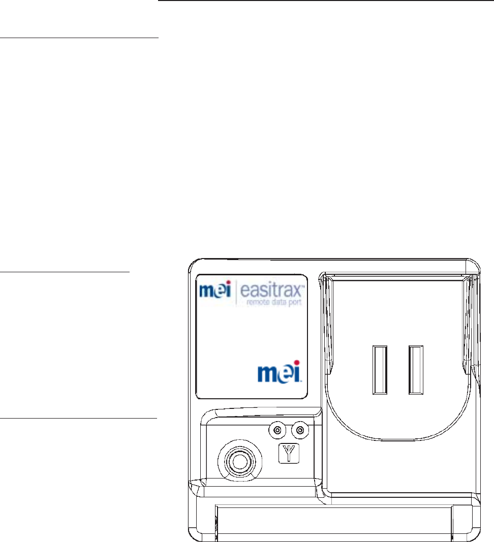
REMOTE DATA PORT
The remote data port is the core of the audit retrieval system. It allows for easy retrieval of cash
transactions and/or product vending cycles. The remote data port has five connection points for
interfacing the port directly or indirectly through data pods to the vending machine.
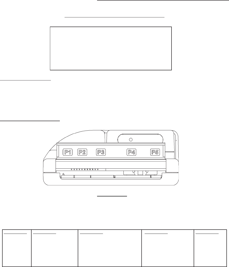
PRODUCT OVERVIEW
SERIAL NUMBER CONFIGURATION
WWYLCCPPPPP
WW - Week Manufactured (01 through 52)
Y- Year Manufactured (2 for 2002)
L- Manufacturing Location
CC - Configuration Code
PPPPP - Sequential Production Number
P1 - 215630001 P2 - 215634004 P3 - 215638002 P4 - 215636003 P5 - 215632005
DDCMP/Printer Electronic Lock Config I/O, Dalla 1 Wire Temp LMM/MMM/DLMM/DMMM VMC Printer
DEX Credit Card Reader RS485 LAN HII2 Interface One Wire Interface
MDB Executive Interface (Master) Optional Battery- Rechargeable Micromech Coin Mech
Executive Interface (Slave) Fill Sw. Detector (Req. External I/F) Printer
Light Detector (Req. External Isolation) ACD
Cash Counter I/F (Req. Isolation) Parallel Coin Mech
Bill Validator
Bottom View

Technical Support 1-800-345-8172 Remote Data Port Page-5
www.meieasitrax.com Revision G1
MEI EASITRAX VT 1000 (LMM)
The MEI EASITRAX VT 1000 is used when monitoring product vend cycles. It allows for high
voltage monitoring of linear vend motors, credit line and cash counter.
PRODUCT OVERVIEW
MEI EASITRAX DATA POD 200 (DMMM)
The MEI EASITRAX data pod 200 is used when monitoring product vend cycles. Its voltage source is
the data port. It allows for 5V logic to monitor matrix vend motors.
Before Installation
¨ Verify that the machine and its components work properly prior to data port installation.
¨ Power MUST be removed from the vendor prior to starting the installation.
¨ Visually inspect machine cables for defects. Adjust/Replace as needed.
¨ Perform a test vend and verify change payback.
¨ Locate a position where the data port is easily accessible, make sure that harnesses
will reach pod(s) and that no objects are obstructing the data port DEX Jack.
¨ Clear all machine errors.
Needed Tools/Supplies
¨ Cable Ties (Supplied by MEI)– Black UV stable cable ties and self-adhesive cable tie bases.
¨ Cleaning materials for vending machines.
¨ General assorted tools such as screwdrivers wire cutters, etc.
Required Installation Standard
It is a requirement that all products and cables are securely fastened to the vendor. The installer will
need to provide UV stable cable ties to securely fasten all cables to the vendor. Any looping of excess
cable must be fastened to the vendor and service loops need to be minimized.
P1
P3
P2 Data Port Interface
Linear Motor
Cash Counter
P1
P2 Data Port Interface
Matrix Motor

Technical Support 1-800-345-8172 Remote Data Port Page-6
www.meieasitrax.com Revision G1
AP 6000 / 7000 Series Snack Machine
Remote Data Port Installation
This machine can utilize the Full Option and Cash Only Option. If you are utilizing the Full Option
perform steps 1 through 15.
Required Components:
Description Part Number
MEI EASITRAX Remote Data Port 216173001
MEI EASITRAX data pod 200 213662012
12 Pin Micromech Cable* 215630006
Electro-Mechanical “Stub” Harness 215636003
MDB Power Cable 215630001
VFM Interface Cable 214977001
24V Supply Cable 215631014
AP 6000/7000 Kit
Motor Monitor Cable 215635012
APi 7x10 Motor Matrix Cable 214891001
APi Series 4k-7k Power Cable 214919001
*Note: The 12 Pin Micromech Cable and the VFM Interface Cable can be used with Mars and Coinco Products.
Installation Instructions
1). Verify proper operation of the payment system. Perform a vend utilizing the bill
validator and coin mech.
2). Power off the vending machine.
3). Install the Electro-Mechanical “Stub” Harness (p/n 215636003) to the P4 connector
of the Remote Data Port (Observe orientation of the key. Ridge connector must face
up).
4). Install the MDB power cable (p/n 215630001) into the plug marked P1 on the Remote
Data Port (Observe orientation of the key. Ridge connector must face up).
5). Using supplied Velcro, attach the remote data port (p/n 216173001) to the machine.
Make sure that the location of the remote data port does not impede machine
operation.
AP-MACHINE INSTALLATION
WARNING
Do Not drill into high voltage wiring
when drilling any necessary mounting holes.

Technical Support 1-800-345-8172 Remote Data Port Page-7
www.meieasitrax.com Revision G1
6) Connect the 12 Pin Micromech Cable (p/n 215630006) from the MEI coin changer to
the Electro-Mechanical “Stub” Harness (p/n 215636003) coming out of the Remote
Data P4 Connector.*
7) Connect the VFM Interface cable (p/n 214977001) from the bill Acceptor to the
Electro-Mechanical “Stub” Harness (p/n 215636003) coming out of the Remote Data
Port P4 Connector.*
8). Connect the Motor Monitor Cable (p/n 215635012) from the Micromech Cable (p/n
215630006) coming from the Coin Mech to the Data Pod 200 (p/n 213662012).
9). Connect the APi 7 X 10 Motor Matrix Cable (p/n 214891001) between the Data Pod
200 (p/n 213662012) and the Vending Machine. Using supplied Velcro, attach the
Data Pod 200 to the machine near the data port. Make sure that the location of the
Data Pod 200 does not impede machine operation or the closing of the cabinet door.
10) Connect the 24V Supply Cable (p/n 215631014) to the MDB power Cable (p/n
215630001) coming from the P1 connector on the Remote Data Port.
11) Connect the APi Series 4k-7k Power cable (p/n 214919001) from the 24V Supply
Cable (p/n 215631014) to the Vending Machine.
12). Secure harnesses as required using wire ties.
13). Power on the vending machine. A solid green LED should be visible through the DEX
socket (J1) located on the front of the data port.
14). Configure the remote data port by using the Palm-Based MEI EASITRAX RDP
Installation Application.**
15). Verify the Remote Data Port installation by using the Palm-Based MEI EASITRAX
RDP Installation Application.
*Coin Changer & Bill Acceptor:
Call our technical support help desk for instructions when connecting to a coin
changer and/or bill acceptor manufactured by a company other than MEI.
**Configuration:
Details pertaining to the configuration of the Remote Data Port are covered in the
section “Palm-Based Installation Application”.
AP-MACHINE INSTALLATION
Technical Support 1-800-345-8172 Remote Data Port Page-8
www.meieasitrax.com Revision G1
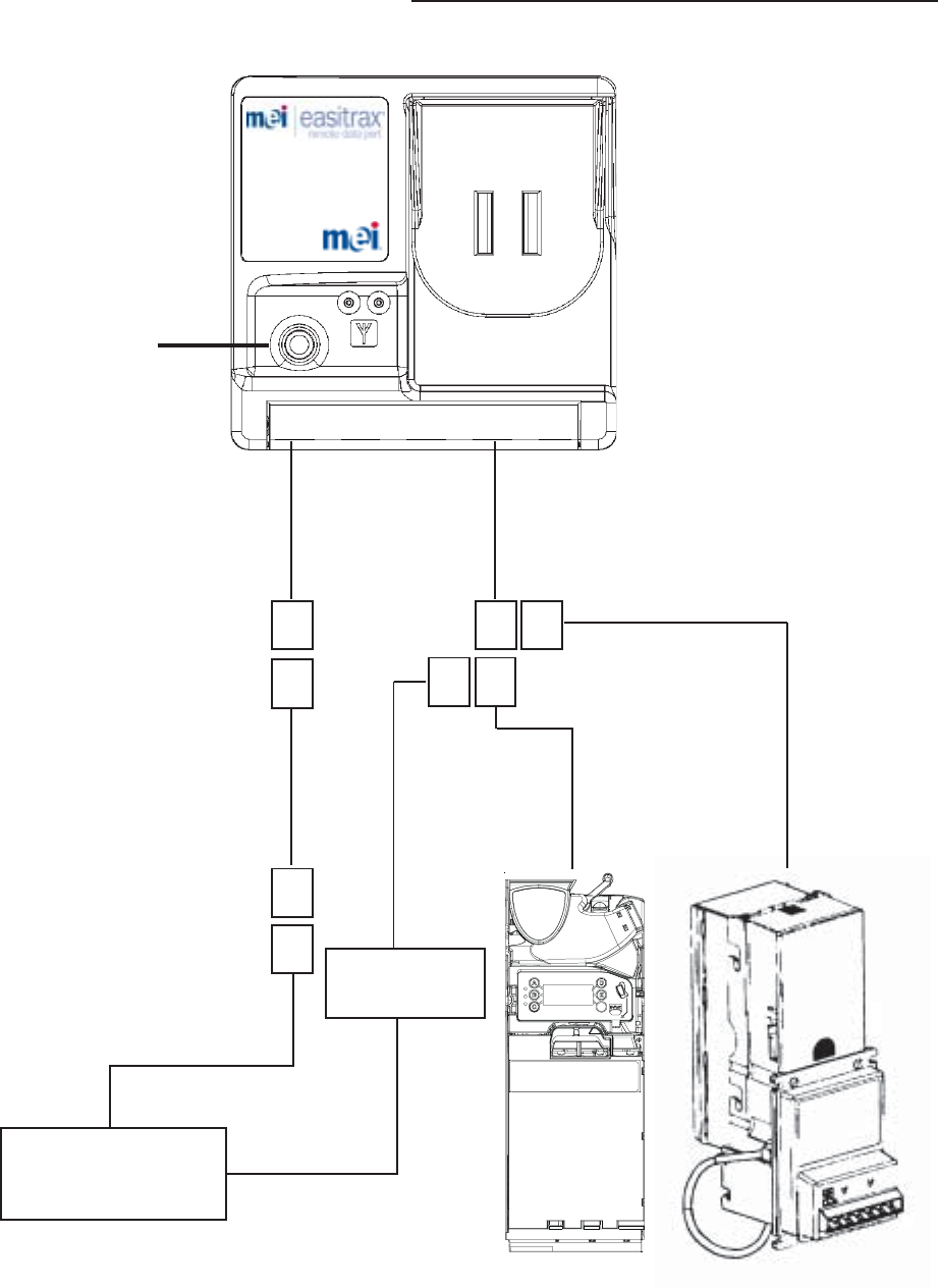
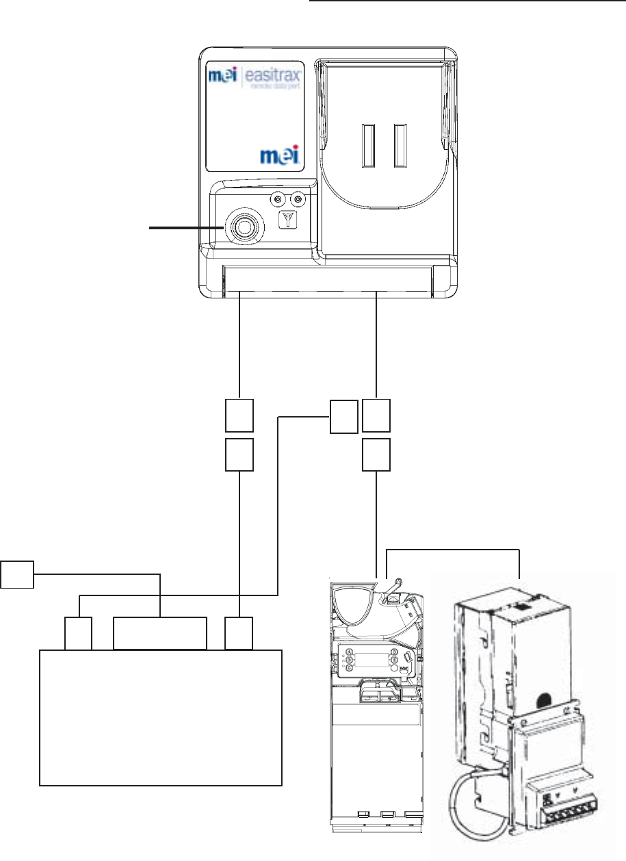
AP-MACHINE DIAGRAM
Part No.:
P1 P2 P3 P4 P5
Dex Socket (J1)
p/n 215630001
p/n 215631014
p/n 215636003
p/n 215630006
Coin
Mech
216173001
Bill Acceptor
p/n 214977001
p/n 215635012
Data Pod 200
p/n 213662012
p/n 214891001
VMC
p/n 214919001

Technical Support 1-800-345-8172 Remote Data Port Page-9
www.meieasitrax.com Revision G1
DN Single Price Machine
Remote Data Port Installation
This machine can utilize the Full Option and Cash Only Option. If you are utilizing the Full Option
perform steps 1 through 13.
Required Components:
Description Part Number
MEI EASITRAX Remote Data Port 216173001
MEI EASITRAX VT 1000 LMM 213663003
ACD Cable 215634009
Electro-Mechanical “Stub” Harness 215636003
MDB Power Cable 215630001
24V Supply Cable 215631014
DN Can Kit
Motor Monitor Cable 215638007
Motor Cable (See Chart on page 12)
Note: The MEI Single Price Changer must have accessory harness p/n (01-12-121) attached
in order for installation. These instructions are for MEI Single Price Coin Changer only.
Installation Instructions
1). Verify proper operation of the payment system. Perform a vend utilizing the bill
validator and coin mech.
2). Power off the vending machine.
3). Install the Electro-Mechanical “Stub” Harness (p/n 215636003) to the P4 connector
of the Remote Data Port (Observe orientation of the key. Ridge connector must face
up).
4). Install the MDB power cable (p/n 215630001) into the plug marked P1 on the Remote
Data Port (Observe orientation of the key. Ridge connector must face up).
5). Using supplied Velcro, attach the remote data port (p/n 216173001) to the machine.
Make sure that the location of the remote data port does not impede machine
operation.
DIXIE-MACHINE INSTALLATION
WARNING
Do Not drill into high voltage wiring
when drilling any necessary mounting holes.

Technical Support 1-800-345-8172 Remote Data Port Page-10
www.meieasitrax.com Revision G1
6). Installing the ACD cable (p/n 215634009):
-Connect the 6 pin ACD connector at the end of the MEI coin mech harness to the
mating 6 pin connector on the ACD cable tap.*
-Connect the ACD Cable tap connector marked P3 to the mating 10 pin connector of
the Electro-Mechanical “Stub” Harness (p/n 215636003) that is already attached to P4
of the Remote Data Port.*
7). Connect the Motor Monitor Cable from the Electro-Mechanical “Stub” Harness (p/n
215636003) to the VT1000 LMM (p/n 213663003).
8). Connect the 24V Supply Cable (p/n 215631014) between the MDB Power Cable (p/n
215630001) and the VT1000 LMM (p/n 213663003).
9). To complete connection, pick appropriate Motor Cable, based on machine model, from
Dixie Narco table on page 12. Use this Motor Cable to connect from the vending
machine door to the 16 pin connector on the VT1000 LMM.
10). Secure harnesses as required using wire ties.
11). Power on the vending machine. A solid green LED should be visible through the DEX
socket (J1) located on the front of the data port.
12). Configure the remote data port by using the Palm-Based MEI EASITRAX RDP
Installation Application.**
13). Verify the Remote Data Port installation by using the Palm-Based MEI EASITRAX
RDP Installation Application.
* Coin Changer:
Call our technical support help desk for instructions when connecting to a coin
changer manufactured by a company other than MEI.
**Configuration:
Details pertaining to the configuration of the Remote Data Port are covered in the
section “Palm-Based Installation Application”.
DIXIE-MACHINE INSTALLATION
Technical Support 1-800-345-8172 Remote Data Port Page-11
www.meieasitrax.com Revision G1
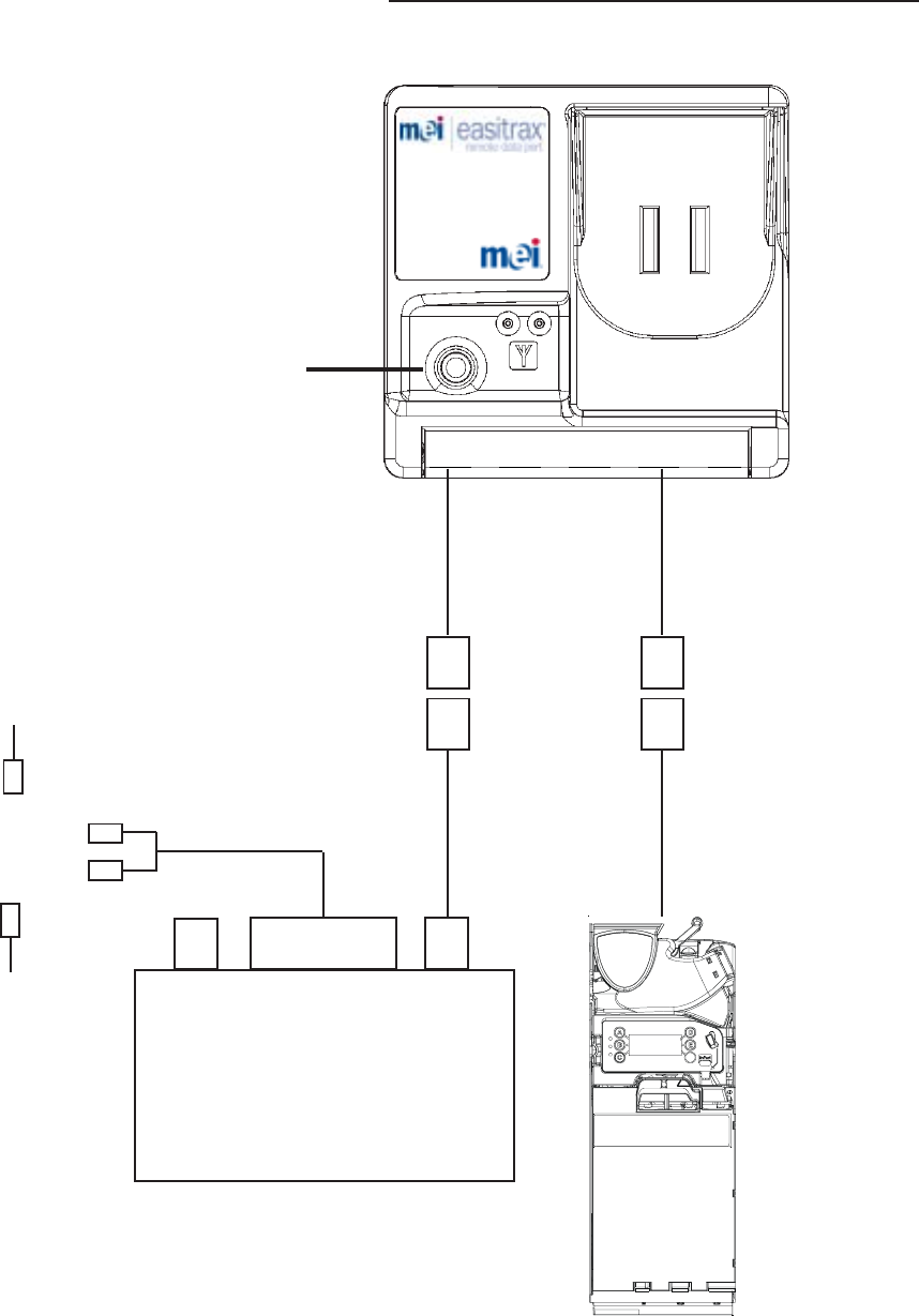
DIXIE-MACHINE DIAGRAM
Part No.:
P1 P2 P3 P4 P5
Dex Socket (J1)
p/n 215630001
p/n 215631014
p/n 215636003
p/n 215634009
Coin
Mech
VT 1000 LMM
p/n 213663003
Machine Door
Harness
( From Key Table p.12)
16 Pin Connector
216173001
p/n 215638007
Bill Acceptor

Technical Support 1-800-345-8172 Remote Data Port Page-12
www.meieasitrax.com Revision G1
KEY:
90 = Series 90 213581001
Rd = Reduced Split
Rs = RS SEQUENCER
Tr = Triple Split 213594001
Ts = TS SEQUENCER 215135017
10 = Ten Clm (2x15 pin)
10s = TC SEQUENCER 215133018
Make/model Qualifier Door
Cable Installed
Cable
DN – 8 803812110.11 Tr Tr
DN – 7 803812150.11 Tr Ts
DN - 7 803 803812150.11 Tr Ts
DN – 7 803812150.11 Tr Ts
DN – 6 803812340.01 Tr Tr
DN - 5 603 803812350.01 Tr Ts
DN - 5 603 803812370.01 Tr Ts
DN – 6 803812380.01 Tr Tr
DN – 5 803812540.01 Tr Tr
DN - 7 803 803815740.01 Tr Ts
DN – 9 803818540.01 10 10s
DN –10 803818550.01 10 10
DN – 8 803819180.01 Tr Tr
DN – 6 803819190.01 Tr Tr
DN –10 803819220.01 10 10
DN – 8 803820440.01 Tr Tr
DN - 7 803 803820450.01 Tr Ts
DN – 8 803820460.01 Tr Tr
DN – 6 803821050.01 Tr Tr
DN – 5 803821410.01 Tr Tr
DN - 7 803 803822920.01 Tr Ts
DN - 7 803 803822920.11 Tr Ts
DN – 6 803823320.01 Tr Tr
DN – 6 803823320.11 Tr Tr
DN – 8 803823610.11 Tr Tr
DN – 6 803825890.01 Rd 90
DN - 7 803 803825980.01 Rd Rd
DN – 8 803826000.01 Rd 90
DN – 8 803826030.01 Rd 90
DN - 7 803 803826670.01 Rd 90
DN - 7 803 903828330.31 Rd 90
DN - 7 803 903829040.31 Rd 90
DN – 8 903829050.11 Rd 90
DN – 8 903829060.11 Rd 90
DN - 7 803 903829070.11 Rd 90
DN – 8 903829080.11 Rd 90
DN – 10 903829180.21 Rd 90
KEY:
90 = Series 90 213581001
Rd = Reduced Split
Rs = RS SEQUENCER
Tr = Triple Split 213594001
Ts = TS SEQUENCER 215135017
10 = Ten Clm (2x15 pin)
10s = TC SEQUENCER 215133018
Dixie Narco Motor Cable Chart
DIXIE-MACHINE INSTALLATION

Technical Support 1-800-345-8172 Remote Data Port Page-13
www.meieasitrax.com Revision G1
RMI 2000 / 8050
MEI EASITRAX Remote Data Port Installation
This machine only utilizes the Cash Only Option.
Required Components:
Description Part Number
MEI EASITRAX Remote Data Port 216173001
MEI EASITRAX VT 1000 LMM 213663003
ACD Cable 215634009
Electro-Mechanical “Stub” Harness 215636003
MDB Power Cable 215630001
24V Supply Cable 215631014
115V Power Tap Cable 215633013
Installation Instructions
1). Verify proper operation of the payment system. Perform a vend utilizing the bill
validator and coin mech.
2). Power off the vending machine.
3). Install the Electro-Mechanical “Stub” Harness (p/n 215636003) to the P4 connector
of the Remote Data Port (Observe orientation of the key. Ridge connector must face
up).
4). Install the MDB power cable (p/n 215630001) into the plug marked P1 on the Remote
Data Port (Observe orientation of the key. Ridge connector must face up).
5). Using supplied Velcro, attach the remote data port (p/n 216173001) to the machine.
Make sure that the location of the remote data port does not impede machine
operation.
6). Installing the ACD cable (p/n 215634009):
-Connect the 6 pin ACD connector at the end of the MEI coin mech harness to the
mating 6 pin connector on the ACD cable tap.*
-Connect the ACD Cable tap connector marked P3 to the mating 10 pin connector of
the electromechanical “Stub” harness (p/n 215636003) that is already attached to P4
of the Remote Data Port.
7). Secure the ACD harness using wire ties.
RMI-MACHINE INSTALLATION
WARNING
Do Not drill into high voltage wiring
when drilling any necessary mounting holes.

Technical Support 1-800-345-8172 Remote Data Port Page-14
www.meieasitrax.com Revision G1
8). To connect power to the Remote Data Port, make the following connections:
Plug in the 6 pin MDB end of the 24V supply cable (p/n 215631014) into the MDB
connector on the MDB power cable (p/n 21563001).
Using the supplied 3M J-hook strips, attach the VT 1000 LMM module (p/n
213663003) near the top hinge of the machine’s door. Make sure that the location of
the VT1000 LMM does not impede machine operation.
Connect the 2 pin plug of the installed 24V supply cable (p/n 215631014) to the 2 pin
connector on the front, left side of the VT1000 LMM (p/n 213663003).
With the latch facing up, connect the 16 pin connector of the 115V power tap cable
(p/n 215633013) into the VT1000 LMM at the front, center opening.
On the vending machine, separate the 2 pin connector to the light transformer located
on the inside part of the machine’s roof. The remaining end of the installed 115V
power tab has a male and female connector that will mate with the now separated light
transformer connectors on the inside part of the machine roof.
9). Power on the vending machine. A solid green LED should be visible through the DEX
socket (J1) located on the front of the data port.
10). Configure the remote data port by using the Palm-Based MEI EASITRAX RDP
Installation Application.**
11). Verify the Remote Data Port installation by using the Palm-Based MEI EASITRAX
RDP Installation Application.
* Coin Changer:
Call our technical support help desk for instructions when connecting to a coin
changer manufactured by a company other than MEI.
**Configuration:
Details pertaining to the configuration of the Remote Data Port are covered in the
section “Palm-Based Installation Application”.
RMI-MACHINE INSTALLATION
Technical Support 1-800-345-8172 Remote Data Port Page-15
www.meieasitrax.com Revision G1
RMI-MACHINE DIAGRAM
Part No.:
P1 P2 P3 P4 P5
Dex Socket (J1)
p/n 215630001
p/n 215631014
p/n 215636003
p/n 215634009
Coin
Mech
VT 1000 LMM
p/n 213663003
115V Supply
from VMC
Male Connector
Female Connector
p/n 215633013
16 Pin Connector
Female Light
Transformer Connector
Male Light
Transformer Connector
216173001

Technical Support 1-800-345-8172 Remote Data Port Page-20
www.meieasitrax.com Revision G1
USA, (902-928Mhz) -
FCC ID: QP8-MEI915WLAN
“This device complies with Part 15 of the FCC Rules. Operation is subject to the following two
conditions: (1) this device may not cause harmful interference, and (2) this device must accept
any interference received, including interference that may cause undesired operation.”
“Warning: Changes or modifications to this unit not expressly approved by the party
responsible for compliance could void the user’s authority to operate the equipment.”
Canada, (902-928Mhz) -
Canada: 1297B-MEI915WLAN
“This Class B digital apparatus complies with Canadian ICES-003.”
“Cet appareil numerique de la classe B est conforme a la norme NMB-003 du Canada.”
“Operation is subject to the following two conditions: (1) this device may not cause
interference, and (2) this device must accept any interference, including interference that may
cause undesired operation of the device.”
“This device has been designed to operate with an antenna having a maximum gain of 0 dB.
Antennas having a higher gain is strictly prohibited per regulations of Industry Canada. The
required antenna impedance is 50 ohms.”
COMPLIANCE