Crate Amplifiers Ca112 Users Manual
CA112 to the manual 2382e973-8cc1-4b54-92ca-a1103a165715
2015-02-02
: Crate-Amplifiers Crate-Amplifiers-Ca112-Users-Manual-424428 crate-amplifiers-ca112-users-manual-424428 crate-amplifiers pdf
Open the PDF directly: View PDF ![]() .
.
Page Count: 6

D
esigned for the performing artist,
Crate’s CA112 Acoustic Amplifier
gives you more of what you want.
More power. More clarity. More control. And,
more freedom. Imagine: microphone quality
sound, without feedback. And without being
“chained” to a mic stand!
More power: twin 50-watt RMS power
amplifiers drive a specially designed dual
voice coil 12” low frequency transducer for
plenty of volume and low end punch.
More clarity: a separate 25-watt RMS
power amp drives a highly efficient Piezo
tweeter for clean crisp highs and natural
midrange blend. A tweeter level control on
the rear panel allows you to adjust the high
frequency output to suit your taste.
More control: three independent channels,
each with its own gain and reverb/effects
controls. The main Instrument channel fea-
tures an “Active/Piezo” switch to properly
match the pickups of your instrument, plus a
three-band rotary EQ with variable contour –
for total control of the critical midrange fre-
quencies. An easy-to-use feedback elimination
circuit with frequency select and cut controls
lets you kill feedback without sacrificing
sound quality. Plus a footswitchable chorus
with depth and rate controls.
The Vocal/Aux channel offers both low
and high impedance inputs for both kinds of
microphones, with phantom power on the
Low-Z input. The third “Aux” channel allows
the use of a rhythm machine, background
tape, or another mic or instrument.
Still more: The master section features
reverb and effects return controls, a five-band
graphic EQ, and the master level control. A
footswitch jack on the rear panel provides
control for reverb and chorus. Level-control-
lable XLR and 1/4” balanced line outs allow
you to patch into house sound boards or
recording consoles, plus an effects loop line-
in/line-out setup allows connection of exter-
nal effects.
The CA112 was designed, evaluated, and
tweaked by musicians and music loving engi-
neers. Highly sophisticated computer driven
assembly machines and highly skilled assem-
blers use only the finest components to pro-
duce each amp. Every cabinet is hand-built
and hand-covered by trained craftsmen. The
final assembled product is tested – and played
– by skilled musician/ technicians. It is only
after the amplifier has passed this barrage of
picky people that it gets packed up and
shipped out.
The CA112 Acoustic Amplifier. Designed to
be its best, so you can sound your best!
About the Crate Acoustic
CA112:
Crate Acoustic amplifiers are
Made With Pride in the U.S.A.
To get this amplifier to sound its best,
read this owner’s guide prior to its use.
To keep this amplifier looking its best,
avoid abrasive cleansers. Wipe the cab-
inet clean using a slightly dampened
cloth. Never use brass cleaners on the
hardware since they could damage
their protective coatings.
Crate continually develops new products, as well as improves
existing ones. For this reason, the specifications and information
in this manual are subject to change without notice.
THIS EQUIPMENT HAS BEEN DESIGNED AND ENGINEERED TO PROVIDE SAFE AND
RELIABLE OPERATION. IN ORDER TO PROLONG THE LIFE OF THE UNITAND PREVENT
ACCIDENTAL DAMAGES OR INJURY, PLEASE FOLLOW THESE PRECAUTIONARY
GUIDELINES:
CAUTION: TO REDUCE THE RISK OF ELECTRIC SHOCK, DO NOT OPEN CHASSIS; DO
NOT DEFEAT OR REMOVE THE GROUND PIN OF THE POWER CORD; CONNECT ONLY
TO A PROPERLY GROUNDED AC POWER OUTLET.
WARNING: TO REDUCE THE RISK OF FIRE OR ELECTRIC SHOCK, DO NOT EXPOSE
THIS EQUIPMENT TO RAIN OR MOISTURE.
CAUTION: NO USER-SERVICEABLE PARTS INSIDE. REFER SERVICING TO QUALIFIED
SERVICE PERSONNEL.
CAUTION: OUR AMPLIFIERS ARE CAPABLE OF PRODUCING HIGH SOUND PRESSURE
LEVELS. CONTINUED EXPOSURE TO HIGH SOUND PRESSURE LEVELS CAN CAUSE
PERMANENT HEARING IMPAIRMENT OR LOSS. USER CAUTION IS ADVISED AND EAR
PROTECTION IS RECOMMENDED IF UNIT IS OPERATED AT HIGH VOLUME.
CAUTION
RISK OF ELECTRIC SHOCK
DO NOT OPEN
CAUTION: TO REDUCE THE RISK OF ELECTRIC SHOCK,
DO NOT REMOVE COVER.
NO USER-SERVICEABLE PARTS INSIDE.
REFER SERVICING TO QUALIFIED SERVICE PERSONNEL.
"IT IS NECESSARY FOR THE USER TO REFER TO THE INSTRUCTION MANUAL"
“ES NECESARIO QUE EL USUARIO SE REFIERA AL MANUAL DE INSTRUCCIONES.”
"REFERREZ-VOUS AU MANUAL D'UTILISATION"
"UNBEDINGT IN DER BEDIENUNGSANLEITUNG NACHSCHLAGEN"
EXPLANATION OF
GRAPHICAL SYMBOLS:
"DANGEROUS VOLTAGE"
“VOLTAJE PELIGROSO”
"DANGER HAUTE TENSION"
"GEFAHLICHE SPANNUNG"
=
=
ATTENTION
RISQUE D'ELECTROCUTION
NE PAS OUVRIR
VORSICHT
ELEKTRISCHE SCHLAGGEFAHR
NICHT OFFENEN
ATTENTION: POUR REDUIRE D'ELECTROCUTION NE PAS
ENLEVER LE COUVERCLE. AUCUNE PIECE INTERNE N'EST REPRABLE
PAR L'UTILISATEUR. POUR TOUTE REPARATION, S'ADRESSER A UN
TECHNICIEN QUALIFIE.
VORSICHT: ZUR MINIMIERUNG ELEKTRISCHER SCHLAGGEFAHR NICHT
DEN DECKEL ABENHMEN. INTERNE TEILE KONNEN NICHT VOM
BENUTZER GEWARTET WERDEN. DIE WARTUNG IS QUALIFIZIERTEM
WARTUNGSPERSONAL ZU UBERLASSEN.
Output Power Rating: 125 watts RMS total system power
Woofer Amp: 2 x 50 watts RMS @1% THD
Tweeter Amp: 25 watts RMS @1% THD
Inst. Channel: Low: +/-15dB @ 80Hz
Mid: +/-15dB @ 400–1.2kHz (Contour)
High: +/-15dB @ 10kHz
Input Impedance: 25k ohm (Active), 2.2M ohm (Piezo)
Input Sensitivity: 22mV RMS (Active), 9mV RMS (Piezo)
Sens. to Eff Send/Line out: 70mV
Max Input Signal: 6v RMS (17v peak to peak)
Feedback Elimination: Freq: variable from 80Hz to 4kHz
Cut: variable from -0 to -30dB
Voc. Ch: Input Impedance: 3k ohm (Lo-Z), 20k ohm (Hi-Z)
Input Sensitivity: 3mV RMS (Lo-Z), 15mV RMS (Hi-Z)
Sens. to Eff Send/Line out: 9mV (Lo-Z), 50mV (Hi-Z)
Max Input Signal: 10v RMS (28v peak to peak)
Aux. Ch: Input Impedance: 20k ohm
Input Sensitivity: 15mV RMS
Sens. to Eff Send/Line out: 50mV
Max Input Signal: 10v RMS (28v peak to peak)
Master EQ’s: +/-12dB @ 80Hz, 330Hz, 1kHz
4kHz, 10kHz
Effects Loop: Line Out 1v RMS,
Line In 1v RMS
Eff Return to Line Out Sens:
50mV
Eff Return In. Impedance: 11k ohm
Eff Send Out. Impedance: 2.2k ohm
Line Out Out. Impedance: 220 ohm (Lo-Z), 2.2k ohm (Hi-Z)
Internal Woofer: 12” dual voice coil w/polypropylene
cone, foam surround, 40oz magnet,
1” voice coil, 2x8 ohms, 100w RMS,
95dB 1w 1m
Internal Tweeter: High efficiency Piezo,
110dB 1w 1m
Internal Crossover: Active electronic type
Power Requirements: 120VAC, 60Hz, 160VA;
100/115VAC, 50/60Hz, 160VA;
230VAC, 50/60Hz, 160VA
Size and Weight: 21-1/2”H x 21”W x 12”D, 44 lbs.
Technical
Specifications:
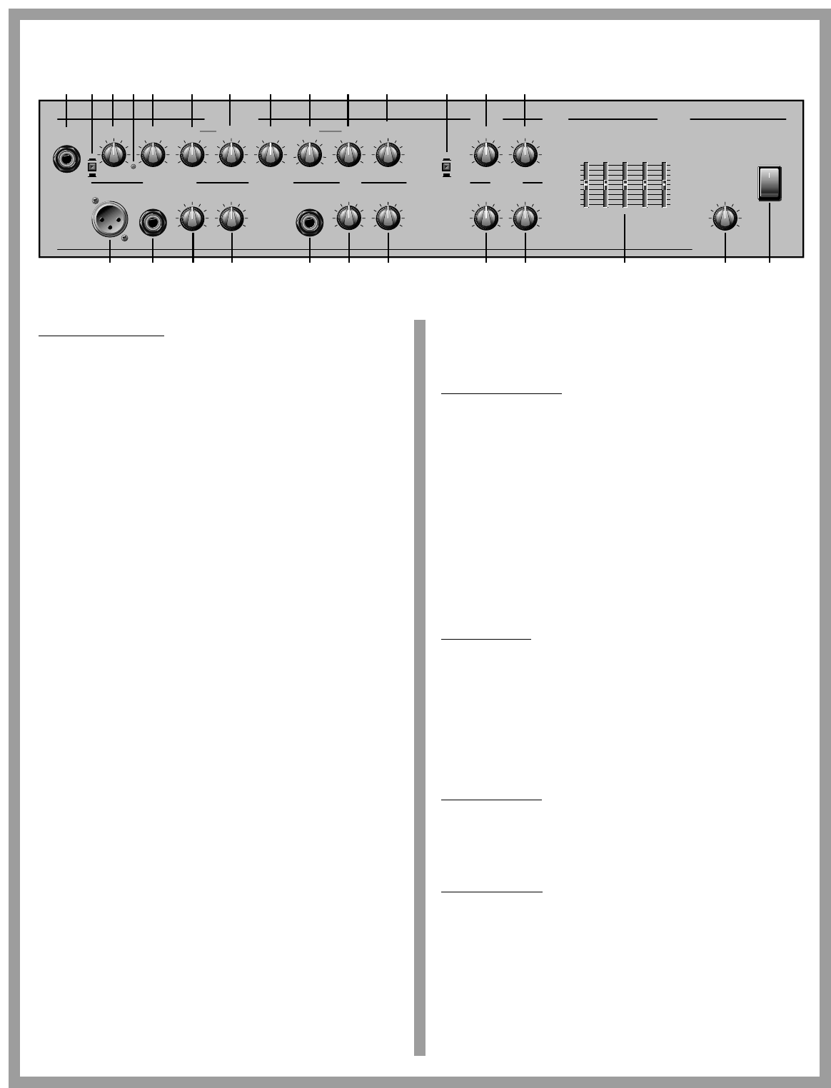
On the
Front Panel:
0 10 0 10
0 100 10 0 100 100 100 10
0 10 500Hz 1.2kHz
0
–15 +15
0
–15 +15
0
–15 +15 0 10
Rev Ret
Effects
Eff Ret
Depth
ChorusInstrument
RateGain
Input
Low Mid Contour High Freq Cut Rev/Eff
Send
0 –30dB
–15dB
Hi ZLow Z Gain
Vocal / Mic
Rev/Eff
Send
Off
On
Active
Peak
Piezo
100Hz 330Hz
1kHz
4kHz 10kHz
+12dB
–12dB
0
+12dB
–12dB
0
Graphic Eq Power
Master
0 10
Level
Crate Acoustic CA112
500Hz
175 1.2k
80Hz 4kHz
GainHi Z
Aux
Rev/Eff
Send
1 2 3 4 5 6 7 8 9 10 11 12 13 14
15 16 1817 19 20 21 22 23 24 25 26
The Instrument channel:
1: Input. The signal output from your acoustic instrument may be con-
nected here by means of a shielded instrument cable.
2: Active/Piezo switch. Use this switch to select the type of pickup on
your instrument. For active electronic pickups, set the switch to
“active” (switch out). For passive/magnetic pickups, set it to “piezo”
(switch depressed).
3: Gain. This serves as the input level control for the instrument channel
of the amplifier. For the best signal to noise ratio set this control so the
Peak LED (#4) flashes when playing your instrument fairly hard.
4: Peak LED. This LED flashes when the signal level into the preamp
approaches clipping. Adjust the Gain control (#3) until a strong signal
from your instrument causes this LED to flash.
5: Low. This serves as the instrument channel’s primary bass control.
Adjust this control to get the best sounding bass response for your
instrument. Excessive boost of the low control can cause an unnatural
howling and should be avoided.
6: Mid. This serves as the instrument channel’s primary midrange con-
trol. Adjust this control to get the best projection and midrange tones
for your instrument. The center point of the mid control is chosen by
the setting of the contour control (#7).
7: Contour. Use this control to set the center point of the mid control
(#6). Set this control at the frequency which gives you the most natu-
ral-sounding midrange tones.
8: High. This serves as the instrument channel’s primary treble control.
Adjust this control so your high notes and harmonic overtones are
lively but not overpowering.
9: Freq. Use this control along with the Cut control (#10) to eliminate
instrument feedback. For information on the proper use of this con-
trol, please read the section entitled “To Eliminate Instrument
Feedback.”
10: Cut. Use this control along with the Freq control (#9) to eliminate
instrument feedback. For information on the proper use of this con-
trol, please read the section entitled “To Eliminate Instrument
Feedback.”
11: Rev/Eff send. Use this control to adjust the amount of internal reverb
and/or external effect (if used) for the instrument channel.
12: Chorus On/Off switch. This switch, when depressed, applies the
internal chorus effect to the instrument channel.
13: Chorus Depth. Use this control to adjust the magnitude of the chorus
effect. Rotating this control clockwise increases the intensity of the
effect.
14: Chorus Rate. Use this control to adjust the rate of the chorus effect.
Rotating this control clockwise increases the rate at which the effect
occurs.
The Vocal/Aux channel:
15: Low-Z input. The signal output from a low impedance microphone
may be connected here by means of a shielded, balanced microphone
cable terminated with an XLR connector. The Low-Z jack has 15 volts
phantom power applied to pins 2 and 3. (Mics not requiring phantom
power will not be affected.)
16: Hi-Z input. The signal output from a high impedance microphone or
a line level signal may be connected here by means of a shielded sig-
nal cable terminated with a 1/4” tip/sleeve connector.
17: Gain. This serves as the input level control for the vocal/aux channel
of the amplifier. Adjust this control for the best mix with the signals
from the other channels.
18: Rev/eff send. Use this control to adjust the amount of internal reverb
and/or external effect (if used) for the vocal/aux channel.
The Aux channel:
19: Hi-Z input. The signal output from a high impedance microphone or
a line level signal may be connected here by means of a shielded sig-
nal cable terminated with a 1/4” tip/sleeve connector.
20: Gain. This serves as the input level control for the aux channel of the
amplifier. Adjust this control for the best mix with the signals from the
other channels.
21: Rev/eff send. Use this control to adjust the amount of internal reverb
and/or external effect (if used) for the aux channel..
The Effects Section:
22: Rev Ret. Use this control to adjust the amount of the internal reverb –
the further you turn to the right the deeper the effect.
23: Eff Ret. Use this control to adjust the amount of effect applied from an
external signal processor (if used).
The Master Section:
24: Graphic EQ. Use these sliders to control the output frequencies indi-
cated below each control. The center position of each control is flat (no
boost or cut). Use the graphic EQ to adjust the output of the CA112 to
best suit your tastes and to compensate for room acoustics.
25: Level. Use this control to set the overall output level of the amplifier.
26: Power Switch. Use this switch to apply power to the amplifier: the
amp is on when the top of the switch is depressed, off when the bot-
tom of the switch is depressed. This switch will illuminate when the
amplifier is on.
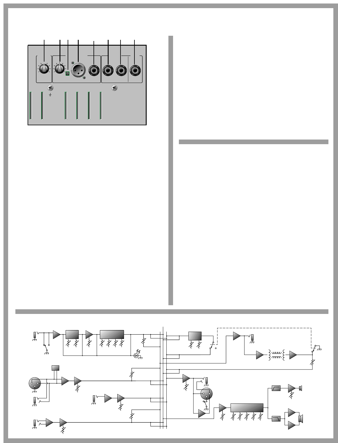
On the
Rear Panel:
Return Send
Low Z
Bal.
Gnd
Lift
High Z
Bal.
Reverb/
Chorus
Line OutputsTweeter Effects
Loop
Foot
Switch
Level
0 10
Level
-50dB 0dB
-6dB
34 33 31 30 29 28 2732
27: Footswitch. Connect the supplied two-button footswitch here for
remote on/off control of the internal reverb and chorus. (When connect-
ed, the footswitch overrides the front panel chorus on/off switch.)
Note: This is a STEREO jack: tip controls the chorus, ring controls the
reverb, sleeve is ground. Use only a footswitch equipped with a stereo
1/4” plug.
28: Effects Loop Send. When using an external signal processor, connect
this jack to the input of the effect by means of a shielded signal cable.
29: Effects Loop Return. When using an external signal processor, connect
this jack to the output of the effect by means of a shielded signal cable.
30: High Z Bal. Use this jack to connect a high impedance, line level signal
to a house sound board, a recording console or an external power ampli-
fier by means of an 1/4” stereo plug-terminated cable. (Ring is signal +,
tip is signal -, and sleeve is ground.)
31: Low Z Bal. Use this jack to connect a low impedance, line level signal to
a house sound board, a recording console or an external power amplifi-
er by means of an XLR-terminated cable. (Pin 1 is ground, pin 2 is signal
+, and pin 3 is signal -.)
32: Ground Lift. This switch, when depressed, electronically disconnects
the low Z balanced output jack’s chassis ground connection. If you expe-
rience excessive noise when using the low Z balanced output jack,
depress this switch.
CA112 Block Diagram:
effects line out
master
instrument
channel
input
aux channel
active piezo freq cut
filter
gain low mid cntr
peak
high
rev/
effect
send
vocal/aux
channel
low-z
input
hi-z
input
phantom
power
tones
80 330 1k
Hz 4k 10k
level
graphic EQ
rev/
effect
send
hi-z
input
gain
gain
effect
return
effect
return
master
level
50w
25w
high pass hi freq
driver
dual
voice coil
low freq
driver
reverb
return
effects
send
spring reverb
low-z
bal.
gnd
lift
hi-z
bal.
level
line out
rev/
effect
send 50w
depth rate
chorus
on off
low pass
foot
switch
To Eliminate Instrument Feedback:
One of the most common problems encountered when amplifying
acoustic instruments, especially in small environments, is feedback.
Acoustic instruments typically have inherent qualities which cause reso-
nant feedback at specific frequencies. Instrument tone controls and sound
board equalizers are helpful in getting rid of the problem, but they typi-
cally operate around relatively wide frequency bands. This almost
always means the musician must sacrifice sound quality in his quest to
do away with feedback. Crate’s feedback elimination circuit isolates only
the offending frequency. Consequently, instrument feedback from the
amplifier can be eliminated without affecting the overall sound.
Chances are, you may not have a problem with feedback at all. In
that case, set the amplifier’s Freq and Cut controls fully counter-clock-
wise. However, if you do encounter feedback while playing, set the Cut
control to -30dB (fully clockwise) and adjust the Freq control until the
feedback is gone. Reduce the Cut to the 12 o’clock position and readjust
the Freq control as needed. Continue reducing the Cut control and read-
justing the Freq control until there is no more feedback with the Cut con-
trol as far counter-clockwise as possible. This approach effectively elimi-
nates instrument feedback without sacrificing the quality of your sound.
33: Line Out Level. Use this control to adjust the output level of the line out
signal. (This control works independently from the amplifier’s master
level control.)
34: Tweeter Level. Use this control to adust the signal output level from the
CA112’s internal tweeter. Rotating this control counter-clockwise
reduces the tweeter’s output level.
Not Shown:
Power cord. Connect the end of this cord to a suitable source of line volt-
age. Refer to the voltage information on the back of the amplifier for its
voltage and current requirements.
Note: This is a grounded plug. To avoid the possibility of electric shock,
DO NOT defeat the ground connection in any way!

www.crateamps.com
©1999 SLM Electronics
A Division of St. Louis Music Co.
1400 Ferguson Avenue
St. Louis, MO 63133
P/N 47-840-01
10/99
