Creatix Polymedia CTX714 802.11b/g WLAN miniPCI Card User Manual CTX714 manual
Creatix Polymedia GmbH 802.11b/g WLAN miniPCI Card CTX714 manual
Users manual
Creatix WLAN Modem Combo
CTX714 V.2
User Manual
This handbook is protected by copyright. It must not be copied, reproduced,
translated or transmitted in electronic media, in whole or in part.
Accuracy of the information is not guaranteed.
Any mention in this handbook of products of other manufacturers is for
information purposes only and represents no misuse of trademarks.
Safety instructions for Data-Fax-Modem
This equipment has been designed and tested in accordance with the
requirements of Standard IEC 950 „Safety of Information Technology
Equipment, Including Electrical Business Equipment“ Extracts from these
requirements according Standard IEC 950:
x The FAX-Modem was evaluated for use in maximum ambient temperature
of 40 °C.
x The FAX-Modem may only be used in countries where the modem is
certified.
x Neither the data transmission cable nor the telephone cable should be
connected or disconnected during a thunderstorm.
mv205a0.402uk
Regulatory Statements
FCC Certification
The United States Federal Communication Commission and the Canadian
Department of Communication have established certain rules governing the
use of electronic equipment.
Part15, Class B
This device complies with Part 15 of the FCC Rules.
Operation is subject to the following two conditions:
(1) This device my not cause harmful interference, and
(2) this device must accept any interference received, including interference
that may cause undesired operation. This equipment has been tested and
found to comply with the limits for a Class B digital device, pursuant to Part 15
of the FCC Rules. These limits are designed to provide reasonable protection
against harmful interference in a residential installation. This equipment
generates, uses and can radiate radio frequency energy and, if not installed
and used in accordance with the instructions, may cause harmful interference
to radio communications. However, there is no guarantee that interference will
not occur in a particular installation. If this equipment does cause harmful
interference to radio or on, the user is encouraged to try to correct the
interference by one or more of the following measures:
- Reorient or relocate the receiving antenna.
- Increase the separation between the equipment and receiver.
- Connect the equipment into an outlet on a circuit different from
that to which the receiver is connected.
- Consult the dealer or an experienced radio/TV technician for
help.
Caution:
1. This equipment complies with FCC radiation exposure limits set forth for an
uncontrolled environment. This equipment should be installed and operated
with minimum distance 20cm between the radiator and your body.
2. This transmitter must not be co-located or operating in conjunction with any
other antenna or transmitter.
3. Changes or modifications made to this equipment not expressly approved
by Creatix Polymedia GmbH may void the FCC authorization to operate this
equipment
Table of Contents
Chapter 0 INSTALLATION WLAN
Chapter 1 INTRODUCTION ................................ 1-1
What is a Modem? ......................................................................................1-1
About this Modem .......................................................................................1-1
The 56K Technology....................................................................................1-2
General Description ....................................................................................1-2
Auto-Answering............................................................................................1-3
Installation Instructions Windows 95/98 ..............................................1-3
Windows 9x and ME......................................1-3
Windows NT 4.0 ............................................1-4
Windows 2000/XP .........................................1-4
Factory Settings .......................................................................................... 1-4
Chapter 2 AT COMMANDS: DATA MODEM ...... 2-1
Guidelines for Using AT Commands .......................................................... 2-1
AT - Attention Code ....................................................................................2-3
The ESC Sequence .................................................................................... .2-3
A - Answer Mode ......................................................................................... 2-4
A/ - Repeat Last Command Line ................................................................ 2-4
B - BELL/CCITT .......................................................................................... 2-4
D - Automatic Dialing and Dialing Parameters ............................................2-5
E – Echo Function ......................................................................................2-6
H – Switch Hook Check (Replace Handset) – Go "On Hook" .................... 2-6
I – Firmware Information..............................................................................2-6
L – Volume Level ........................................................................................ .2-6
M – Switching the Loudspeaker On and .....................................................2-6
N – Recognizing Type of Modulation...........................................................2-7
O – Return to online Operation....................................................................2-7
Q – Modem Messages On / Off .................................................................. 2-7
S – Reading and Modifying Registers ........................................................2-7
V – Verbal or Numeric Modem Messages ..................................................2-7
W – Controlling Connect Messages ........................................................... 2-8
X – Result Code Type/Call Progress .......................................................... 2-9
Y – Long Space Disconnect .......................................................................2-9
Z – Reset Modem/Record Stored Profile .................................................... 2-9
&C – DCD (Data Carrier Detect) Option......................................................2-9
&D – DTR (Data Terminal Ready) Option ................................................2-10
&F – Loading the Factory Settings ...........................................................2-10
&G – Guard Tone .....................................................................................2-11
&K – Select Serial Port Flow Control ........................................................2-11
&S – DSR (Data Set Ready) .....................................................................2-11
&T – Data Mode Self-Test Command .......................................................2-11
&V – View Active Configuration and Stored Profiles ................................2-12
&W – Storing a set Profile .........................................................................2-12
&Y – Selecting a Start Configuration .........................................................2-12
&Z – Telephone Number Storage..............................................................2-13
+MS – Select Modulation. .........................................................................2-13
\A – MNP Block Size ................................................................................. 2-16
\B – Sending a Break Signal...................................................................... 2-16
\C – Set Auto-Reliable Buffer .................................................................... 2-16
\G – Set Modem Port Flow Check ............................................................2-16
\J – bps Rate Adjust Control. .................................................................... 2-17
\K – Set Break Control ..............................................................................2-17
\N – Set Operating Mode ..........................................................................2-18
\Q – Set Serial Port Flow Control...............................................................2-18
\T – Set Inactivity Timer .............................................................................2-19
\X – Set XON/XOFF-Pass Through...........................................................2-19
-J – Set V.42 Detect Phase ......................................................................2-19
%C – MNP5 Data Compression Control ...................................................2-19
%E – Auto-Retrain Control .......................................................................2-20
%G – Rate Renegotiations ........................................................................2-20
"H – V.42bis Compression Control ........................................................... 2-20
"O – V.42bis String Length .......................................................................2-20
Chapter 3 MODEM MESSAGES ........................ 3-1
Chapter 4 S-REGISTERS ................................... 4-1
S0 – Number of Ring Characters before Modem engages .........................4-2
S1 – Ring Character Counter .....................................................................4-2
S2 – Esc Sequence Character ....................................................................4-2
S3 – Carriage Return Character ................................................................. 4-2
S4 – Line Feed Character............................................................................ 4-2
S5 – Backspace Character .........................................................................4-2
S6 – Waiting Time for Dial Tone .................................................................4-3
S7 – Waiting for Carrier Signal ................................................................... 4-3
S8 – Pause Time after Comma ...................................................................4-3
S9 – Answer Time after Carrier Recognition 4-3
S10 – Delay between Carrier Loss and Hanging Up...................................4-3
S12 – Guard Time for Esc Sequence .........................................................4-4
S14 – General Options ................................................................................4-4
S16 – Modem Test Options ........................................................................ .4-5
S18 – Test Timer ........................................................................................4-5
S21 – V.24/General Options........................................................................4-5
S22 – Loudspeaker/Authorized Modem Messages .................................... 4-6
S23 – General Options ...............................................................................4-6
S25 – DTR Delay Time ............................................................................... 4-7
S27 – General Options ...............................................................................4-7
S30 – Inactivity Timer ..................................................................................4-7
S33 – Sleep Modem Timer .........................................................................4-8
S37 – Maximum Line Speed Attempted .....................................................4-8
TECHNICAL INFORMATION.................................. A-1
GLOSSARY ................................................................................................A-1
CCITT RECOMMENDATIONS ...................................................................A-2
Technical Specifications ..............................................................................A-3
Support ........................................................................................................A-4
COUNTRY CODE CONVERSION
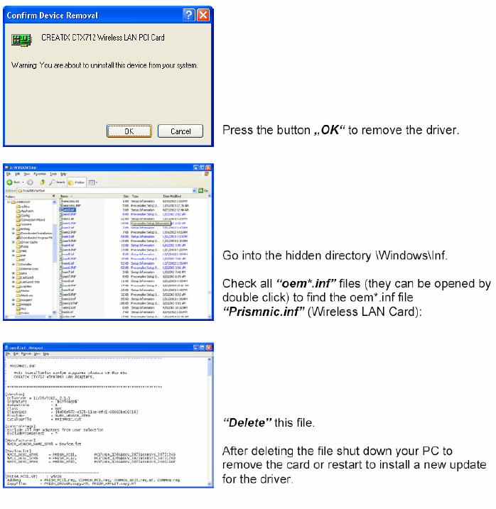
when using new drivers
Drivers concerned: W2K/XP drivers
CHAPTER 0 INSTALLATION WLAN
Chapter 1 INTRODUCTION
The Data Modem you have purchased represents the latest state of the art in
data communication; its comprehensive facilities provide all you will need for
professional data transfer purposes. Due to the limitation this equipment
allows you to receive data with up to 54kbps from your Internet Service
Provider (ISP). The maximum transmission speed is 33.6kbps. Fax
transmission and reception is working up to 14.4kbps.
What is a Modem?
The word “Modem” is derived from the terms “MOD-ulator” and “DE-
modulator”. Putting it more simply, it is a device which modulates digital
information into an analogue carrier signal (tones) and demodulates the carrier
signals which it receives, changing them back into digital data. This permits
the transmission of data along wires, between data terminal equipment
(computers, terminals, etc…).
About this Modem
This modem operates as a full duplex, voice-band modem, where signal
transmissions are made in both directions simultaneously and the analogue
signals which are transmitted are in the voice-band of the telephone network.
Data transmission between modem and terminal unit is in serial form - in other
words, the individual data bits are sent, one after another, along a single
transmission or receiving line. At this stage, a word of explanation regarding
synchronous and asynchronous data transmission. In the synchronous mode,
additional synchronization signals are required, to synchronize the
transmission and reception signals. In the asynchronous mode
synchronization is by means of “start-bits” and “stop-bits” which mark the
beginning and end of each data word. The modem can dial by itself and also
react automatically to incoming calls. The information it needs in order to dial a
telephone number, together with the various configuration commands, are
provided by the respective data terminal equipment via the same serial
interface which is used to send the data. In this mode, the system operates
with the so-called “AT” command set.
INTRODUCTION 1-1

The 56K Technology
The V.90 modem represents the latest V.90 technology. This allows receive
data rates of up to 57.333 kbps over PSTN (public switched telephone
network) only in connection with equipment-compatible ISPs (Internet Service
Provider): however, due to the limited power levels of the PSTN the receive
speed is limited to 54 kbps.
Figure 1 Connection Modem to Modem
analog digital analog
Modem Switch Switch Modem
Figure 2 Connection Modem to Internet Service Provider ISP
analog digital
Modem Switch Internet Provider ISP
General Description
x Up to 54 kbps receive data rates in V.90 mode
x Fax send and receive up to 14400 bps
x (Fax group 3, according to V.29, V.27ter, V.17)
x Max. transmission speed up to 33.6 kbps
x Asynchronous communication between modem and computer
x V.42bis data compression
x V.42 and MNP2-4 error correction
x Effective data rate up to115.200 bps (V.34 and V.42bis)
x Number storage for 4 telephone numbers
x Automatic baudrate-adaption up to 115.200 bps
x AT-command set
x Voice capabilities
x Internal speaker
x Win 9x PnP
1-2 INTRODUCTION

Auto-Answering
With the delivered Software you can use your Modem like an answering
machine. Voicemail can be recorded over the soundcard. To replay recorded
voice or messages you can use a soundcard.
Installation Instructions
1. Plug in the PCI-Card into a free PCI Slot of your PC.
2. Connect the modem card to the enclosed telephone cable and your
analogue telephone connection (RJ11-socket).
Installation under Windows 95/98
Windows 9x will recognize the modem after a reboot of your PC. Put in the CD
with the driver when Windows 9x asks for it and follow the instructions on the
screen. Please read the instructions for the installation of new hardware in
your Windows-Manual.
Installation under Windows 9x and ME
After installing the PCI cards start the computer. The computer will display the
message -> New hardware found –> PCI Communication Controller (single)
and the hardware assistant will be started. Search for -> the best driver for the
device (recommended). To do this insert the CD supplied with the hardware,
which contains the driver. Confirm the messages from the hardware assistant
using Continue when it finds the driver. The Windows driver database is
updated and the assistance can then be completed by clicking on -> Finish.
Another hardware component -> Serial Voice Device will also be found. To
install the driver enter the CD drive again. The installation will then be
completed with the -> HAM settings, where you click on -> OK to accept the
settings.
Installation under Windows NT 4.0
Unpack the driver (diskette or Internet) into a temporary folder. After installing
the card and starting your computer, click on -> Start -> Run using the left
mouse button and run the file -> setup.exe from the driver directory (either on
the diskette or, if you have downloaded the driver from the Internet, enter the
directory into which you unpacked the driver). The installation assistant is now
started and will guide you through the installation and install the drivers.
Complete the setup process by clicking on -> Finish.
INTRODUCTION 1-3

To use the modem in a Dial-Up Network, it must be added to the RAS service
-> Start – Settings – Control Panel – Network (refer to the instructions in the
Windows manual).
To uninstall, remove the entry of the card in the -> Control Panel under ->
Modems and uninstall the installation software using -> Control Panel –
Software.
Installation under Windows 2000
Unpack the driver (diskette or Internet) into a temporary folder.
After installing the card and starting your computer, the operating system will
show the message New hardware -> PCI Communication Controller (single)
and the hardware assistant will be started. Search for -> the best driver for the
device (recommended) and enter the directory into which you unpacked the
driver. Windows 2000/XP will state that it has not found a digital signature.
Continue the installation anyway by clicking on -> Yes. Confirm the messages
from the hardware assistant using Continue when it finds the driver. Finally the
hardware assistant will have installed the required software and can be ended
by clicking on -> Finish. The HAM card should now be available in -> Control
Panel -> Telephone and Modem Options -> Modems.
=> Now you can configure and use the modem with the communications-,
fax- and Voiceprograms.
Factory settings
To make it easier for you to use your modem, two basic settings have been
made at the factory, which are suitable for most of the connections. These
settings can be activated with the “&F” command. In the fax mode or voice
mode, the relevant software will carry out control of modem settings for you.
x For Data Transmissions select AT&F0. In this condition, the modem will
attempt to create an error-corrected connection with data compression,
depending on the capability of the remote side.
1-4 INTRODUCTION
Chapter 2 AT COMMANDS:
DATA MODEM
Guidelines for Using AT Commands
The modem is programmed with AT commands from the data terminal
equipment (computer, PC or terminal) and thus also receives instructions to
cover automatic dialing. The communications or fax software will carry out
most of these operations for you, so that in general circumstances you do not
need to have a detailed understanding of the commands which are described
below.
The modem must be in Command mode before it can accept commands. In
this condition, all the characters sent from the computer are interpreted as
commands and, where appropriate, confirmed by a modem message on the
screen. When a connection is set up to a remote modem, the modem will
switch to data mode and transfer all the characters it receives to the other
party.
The modem can be switched from an existing connection, back into the
command mode, by using the Esc Sequence (+++), without breaking off the
connection to the remote modem. In this status, any commands which are
entered will not be transferred to the remote modem.
The modem is activated by AT commands, the subsequent value of which will
modify the form of the command. Modem messages provide information on
the form of the commands.
In the Hayes Command Set, commands are entered by the character
sequence AT (at) and can also be entered as a list of commands with or
without spaces between the individual commands. The “Backspace” key is
used for deleting. Commands can be entered in upper-case or lower-case, but
all characters for a given command must use the same case. In the command
mode, the modem automatically recognizes data frames and data speed.
=> AT commands can be transferred to the modem at the following data
speeds: 115 200, 57600, 38400, 19200, 9600, 4800, 2400, and 1200 bps
Examples of Command Syntax:
ATX3<CR>
ATQ0<CR>
ATDT12345<CR>
Individual commands ending with the <CR> Enter key, can be entered in a
different manner with the same effect, by inserting as many spaces as you
need, to make the command easier to visualize
ATX3QODT12345<CR> or:
AT X3 Q0 DT 12345<CR>
AT COMMANDS: DATA MODEM 2-1
Table 1 Modem Commands
Standard Commands
ATA Answer mode: Modem monitors telephone line
A/ Repeat last command line; entered without “AT”
ATB Switching between BELL/CCITT Standards at 300 or 1200 bps
ATD Enter automatic dialing
ATE Controlling of echo modem commands on screen
ATH Break off an existing connection
ATI Information on Modem product code
ATL Loudspeaker volume control
ATM Switch on and off loudspeaker
ATN Select Data Rate Handshake
ATO Return to Online-mode after entering Esc sequence
ATQ Controlling modem messages
ATS Read and modify modem register(s)
ATT Select Tone dialing
ATV Modem message format (verbal or numeric)
ATW Directing speed messages
ATX Modem function during dialing; modem messages
ATY Long Space Disconnect
ATZ Modem Reset and Load one of the stored modem profiles
+++ Escape Sequence to return temporarily to Command mode
AT&C Controlling M5 (DCD) Signal at the serial interface
AT&D DTR Option
AT&F Load the factory setting
AT&G Switch on a Guard Tone
AT&K Flow Check
AT&R Controlling M2 (CTS) and S2 (RTS) Signal at the serial interface
AT&S Controlling M1 (DSR) Signal at the serial interface
AT&T Modem test functions
AT&V Displaying current configuration
AT&W Storing Modem settings
AT&Y Selecting the configuration which will be active after modem start
AT&Z Storing telephone numbers
AT+MS Select Modulation
Extended MNP- and V.42bis-Befehle
AT\A MNP Block Size
AT\B Transmit Break
AT\G Set Modem Port Flow Control
AT\J bps Rate Adjust Control
AT\K Set Break Control
AT\N Set Operating Mode
AT\Q Set Serial Port Flow Control
2-2 AT COMMANDS: DATA MODEM
Extended MNP- and V.42bis-Commands
AT\T Set Inactivity Timer
AT\X Set XON/XOFF Pass-Through
AT-J Set V.42 Detect Phase
AT%C MNP 5 Data Compression Control
AT%E Auto Retrain Control
AT%G Rate Renegotiations
AT"H V.42 bis Compression Control
AT"O V.42 bis String Length
AT - Attention Code
The AT (Attention) Code, which introduces each command line, can be
entered in upper-case or lower-case characters. Several commands
(separated by spaces if desired) can be positioned one after another, in one
line. A command line must end with the ASCII character which is stored in the
S3 or S4 Register (or with both together). The standard value for S3 is
Carriage Return (<CR>=13 decimal) and Line Feed (<LF>=10 decimal) for S4.
A command line without <CR>,<LF> will remain in the command buffer until
<CR>,<LF> is entered, or until the action is broken off with <Cntrl-X>. Once
<CR>,<LF> has been received, the modem carries out the commands
following the AT and answers with an appropriate modem message.
The maximum length of a command line is 40 characters. If the capacity of the
command buffer is exceeded, the modem issues an Error message.
=> The AT code enables the modem to recognize the speed, parity and
character length of the communication program
The ESC Sequence
If the modem has established a data connection, you can enter more
commands at any time, without breaking off the connection. This is achieved
by sending three ASCII characters (S2 Register) from the computer to the
modem. The standard setting is the “+” character. In order for this to be
interpreted as the ESC sequence, certain time limits must be observed in
entering the plus-characters. Before the first and after the last character, a
Guard time is required (the standard is 1 second) and the individual characters
must not be separated from each other by longer than this time period.
AT COMMANDS: DATA MODEM 2-3
A - Answer Mode
When the Acommand is entered, the modem switches to the “Off-Hook”
condition when ringing appears in the answer mode and takes over control of
the telephone line connected. In this way, the modem transmits in the upper
frequency band (upper channel).
If further commands are entered after the Acommand before a connection has
been made, the modem interrupts the establishment of a connection, switches
to command mode and issues a NO CARRIER message.
If no carrier is received from the remote station after the waiting time which is
set in the S7 Register, the modem responds with a NO CARRIER message
and returns to command mode. If the modem does receive the carrier signal, it
issues a CONNECT message and switches to Data mode.
=> If the handset is not replaced after the data transmission has been
completed, the connection remains online and you will continue to pay for this !
A/ - Repeat Last Command Line
The A/ command causes the modem to repeat the command line which is
stored in the command buffer, e.g. it will dial again, if the line is busy. This
command is entered without AT and no reply is issued.
=> A command line remains in the repetition buffer until the modem
receives a new command. The data format should not be modified in the
meantime.
B - BELL/CCITT Standard
The B command permits change-over between CCITT and Bell standards at
300 or 1200 bps. At 300 bps, this command will select between Bell 103 and
CCITT V.21, while at 1200 bps it will select between Bell 212A and CCITT
V.22.
ATB0 CCITT V.22, V.21
ATB1 Bell 212A, Bell 103 (factory setting)
=> The Bcommand refers only to connections at 300 or 1200 bps. All other
speeds use the CCITT standard.
2-4 AT COMMANDS: DATA MODEM
D - Automatic Dialing and Dialing Parameters
The D command instructs the modem to go on-line and to dial. If this
command is entered without parameters, the modem will go on-line in
Originate mode. The following characters are authorized in the dialing
sequence:
0 - 9 The digits of the telephone number
P, T In the Dial command, these parameters switch to pulse-dialing (P) or
to tone-dialing (T) until the other parameter is entered. The standard
setting is tone-dialing.
WDialing tone recognition. When this parameter is entered, the modem
will not continue dial until it has recognized the sign that the line is
free. This is an advantage in branch exchanges, where it is not
always possible to guarantee immediate access to a line.
, Dialing pause (2 sec). This command may not be used in the dialing
sequence when the modem is supposed to wait for a new dial-tone.
The W-Parameter must be used in this case.
A-D,*,# Additional characters when tone-dialing
S=n Dialing number which is stored with &Zn
!Call exchange by Flash
;H Modem as automatic dialing device. Here, the dialing sequence is
terminated by a semi-colon, followed by the Hcommand. The
modem goes off-line after dialing and you can take over the
conversation using a telephone. The handset must be lifted during
the dialing process.
Example of how to set up a Dial Command
ATD T0, 02212971
With this, a private automatic branch exchange using tone-dialing dials zero, in
order to obtain an exchange line. The modem then waits two seconds to dial
the rest of the telephone number.
Example of the Automatic Dialing Function
ATD T0, 02212971;H
If you lift the handset during the dialing process, you can take over the
connection yourself.
=> Where appropriate, ask the manufacturer of your private automatic
branch ex-change what specific features need to be taken into account in the
dialing procedure
=> If the handset is not replaced after the data transmission has been
completed, the connection remains made and you will continue to pay for this!
AT COMMANDS: DATA MODEM 2-5
E – Echo Function
The E command determines whether the modem will issue an echo of the
command which is entered.
ATE0 Echo disabled
ATE1 Echo enabled (factory setting)
H – Switch Hook Control (Replace Handset) – Go "On Hook"
The Hcommand will break off the existing telephone line connection (the
modem “hangs up”) and the connection to the remote modem is cut off. After
the H command, any other commands in the same line are ignored.
=> This command can only be entered after an existing data link has been
quitted by using the Esc sequence.
I – Firmware Information
ATI0 Report product code
ATI1 Modem chip firmware version #
ATI2 Verifies ROM checksum
ATI3 Reports chipset name
ATI4 Reserved
ATI6 Country Code
L – Volume Level
The loudspeaker enables you to follow acoustically as the connection is
established and data are transmitted.
ATL0,1 Low speaker volume
ATL2 Medium speaker volume (factory setting)
ATL3 High speaker volume
M – Switching the Loudspeaker On and Off
ATM0 Speaker always OFF
ATM1 Speaker on until carrier present (factory setting)
ATM2 Speaker always ON
ATM3 Speaker OFF during dialing, and on until carrier
2-6 AT COMMANDS: DATA MODEM
N – Recognizing Type of Modulation
This command commands the automatic recognition of the type of modulation.
ATN0 When originating or answering, connect only at the data rates
specified by the modulation.
ATN1 When originating or answering, begin handshaking at the modulation
data rate. If the remote modem does not support the specified
modulation data rate, fall down in data rate or modulation to the
highest compatible data rate.(factory settings)
O – Return to On-Line Operation
The O command causes the modem to return to Online mode, which had been
left temporarily, using the Esc sequence. With the remote modems still online,
you can continue data transmission.
Q – Modem Messages On / Off
ATQ0 Result codes enabled(factory setting)
ATQ1 Result codes disabled
S – Reading and Modifying Registers
This command gives access to the internal modem registers. See chapter 4 for
details of the possible values.
ATSn=v This sets Register n to the (decimal) value v
ATSn=v? This sets Register n to the (decimal) value v and sends the new
value for checking
ATSn? This reads Register n and gives its value in decimal form
V – Verbal or Numeric Modem Messages
The V command determines the type of message which the modem returns to
the computer.
ATV0 Numeric form
ATV1 Verbose (text) form (factory setting)
AT COMMANDS: DATA MODEM 2-7
W – Controlling Connect Messages
This command controls the format of CONNECT messages.
ATW0,1 CONNECT result code reports DTE speed
ATW2 CONNECT result code reports DCE speed
ATW3 CONNECT result code reports DTE data rate, modulation mode,
error correction, data compression, DCE transmitter speed and DCE
receiver speed when the mode is configured for verbose V1 (text)
response codes. For numeric responses V0, the modem responds
with the W0 numeric response codes. The verbose response codes
use the following format:
CONNECT (DTE data rate)/(modulation)/(error correction)/ (data
compression)/TX=(DCE transmit data rate)/RX=(DTE receive data
rate)
Modulation types include:
V21, V22, V22B, V23C, V32, V32B, V32B, V34
Error correction types include: NONE, LAPM, MNP
Data compression types include: NONE, V42B, MNP5
For example:CONNECT 115200/V34/LAPM/V42B/TX=28800/RX=28000
ATW4 CONNECT result code reports DTE protocol, data compression, and
DTE data rate when the mode is configured for verbose V1 (text
response codes). For numeric responses V0, the modem responds
with the WO numeric response codes. The verbose response codes
use the following format: (DTE protocol) (date compression) (line
speed)
Error correction types include: NONE, LAPM, MNP
Data compression types include: NONE, V42B, MNP5
For example: PROTOCOL: LAPM; COMPRESSION: V42B; CONNECT 33,600
2-8 AT COMMANDS: DATA MODEM
X – Result Code Type/Call Progress
This command determines which modem result codes are enabled.
Additionally, this command specifies whether busy and dial tone detection are
enabled or disabled..
ATX0 Result codes 0-4 enabled. Busy and dial tone detect disabled.
ATX1 Result codes 0-5, 10 and above enabled. Busy and dial tone detect
disabled.
ATX2 Result codes 0-6, 10 and above enabled. Busy detect disabled and
dial tone detect enabled.
ATX3 Result codes 0-5, 7, 10 and above enabled. Busy detect enabled
and dial tone detect disabled.
ATX4 Result codes 0-7, 10 and above enabled. Busy and dial tone detect
enabled (factory setting).
Y – Long Space Disconnect
This command determines whether the modem disconnects after receiving 1.6
seconds of silence and whether the modem sends a period of silence to the
remote modem before disconnecting.
ATY0 Disables long space disconnect (factory setting)
ATY1 Enables long space disconnect. The modem disconnects after
receiving 1.6 seconds of silence from the remote modem.
Additionally, after receiving an ATH0 command, the modem sends at
least 4 seconds of silence before hanging up.
Z – Reset Modem/Recall Stored Profile
This command causes the modem to go on-hook (hang-up), perform a warm
reset, and load user-configuration profile ’n’ (previously stored in the NVRAM)
into the active profile. The Zn command must be the last command in
command string, as it causes all subsequent commands to be ignored.
ATZ0 Resets the modem and recalls user profile 0.
ATZ1 Resets the modem and recalls user profile 1.
&C – DCD (Data Carrier Detect) Option
This command controls how to modem functions in relation to the DCD or
RLSD signal.
&C0 State of carrier from remote modem is ignored. DCD is always on.
&C1 State of carrier from remote modem is tracked. DCD reflects the
state of the received carrier.
AT COMMANDS: DATA MODEM 2-9
&D – DTR (Data Terminal Ready) Option
This command controls how the modem responds to DTR. After toggling DTR,
the host should wait 200 ms before modifying the UART registers or sending a
new command to the modem. This is done because the modem does not send
an ’OK’ message to indicate it has performed the requested function.
AT&D0 In asynchronous mode (&Q0), the modem ignores DTR.
AT&D1 The modem switches from data mode to command mode when
an on-to-off transition of DTR occurs.
AT&D2 An on-to-off transition of DTR causes the modem to go on-hook
(hang-up). While DTR is off, auto-answer is disabled.
AT&D3 An on-to-off transition of DTR re-initializes the modem. The re-
initialize procedure performs the same function as a power-up
reset, except that the UART registers are not reconfigured.
&F – Loading the Factory Settings
This command loads command defaults and S-Register factory defaults into
the active configuration and configures the modem for data mode.
A Selection of &F0 Factory Settings
E1 Echo enabled
L2 Middle speaker volume
M1 Speaker on until carrier present
Q0 Result codes enabled
V1 Verbose (text) form
Y0 Disables long space disconnect
X4 Result codes 0-5, 7, 10 and above enabled. Busy detect enabled
and dial tone detect diaabled
&C1 State of carrier from remote modem is tracked. DCD reflects the
state of the received carrier.
&G0 Guard tone disabled
&R1 RS always On
&T5 Denies RDL request from remote modem
S0=0 No automatic answer
\N3 V.42 - Auto-Reliable Mode
=> (Further settings are covered by the descriptions of the individual
Commands and Registers).
2-10 AT COMMANDS: DATA MODEM
&G – Guard Tone
This command controls whether the modem sends out guard tones while
connected to a remote modem (for ITU-T V.22 bis {1200 bps} and V.22 bis
{2400 bps} connections only). Guard tones are sent by the answer modem to
disable Central Office echo cancelers.
AT&G0 Guard tone disabled (factory setting)
AT&G1 550 Hz guard tone enabled
AT&G2 1800 Hz guard tone enabled
&K – Select Serial Port Flow Control
This command specifies the DTE-to-modem flow control. Software flow control
uses the characters XOFF (13h) and XON (11h) to stop and start data
transmission, respectively, both to and from the DTE. Bi-directional hardware
flow control uses RTS/CTS to stop and start data from the modem
AT&K0 Disables flow control
AT&K3 Bi-directional hardware flow control - RTS/CTS
AT&K4 XON/XOFF software flow control
&S – DSR (Data Set Ready)
This command controls how the modem treats the DSR signal.
&S0 DSR circuit always on
&S1 DSR circuit is on during handshaking, off in test or idle modes. DSR
is off when the carrier is lost.
&T – Data Mode Self-Test Command
This command is used in data mode to initiate and terminate loopback tests for
testing modem-to-modem and DTE-to-modem data communication integrity.
AT&T0 Terminate test in progress
AT&T1 Local analog loopback.
AT&T4 Grants RDL request from remote modem
AT&T5 Denies RDL request from remote modem
AT&T6 Remote digital loopback
AT&T7 Remote digital loopback with self-test
AT&T8 Local analog loopback with self-test
=> You can use the Test Timer (Register 18) to end a test loop;
alternatively, once you have entered the Esc sequence (+++), you can enter
the command AT&T0.
AT COMMANDS: DATA MODEM 2-11
&V – View Active Configuration and Stored Profiles
This command causes the modem to display the command and S-Register
information contained in the active user profile and in one or two stored
profiles. The command &V0 displays the active profile and the stored profile 0;
&V1 displays the active profile and the stored profile 1. The information in the
active profile is stored into the user profiles with the &Wn command. &W0
stores the active profile into the stored profile 0; &W1, the stored profile 1.
&V0 Stored profile 0
&V1 Stored profile 1
Table 2 Current Modem Configuration (Example)
at&v1
ACTIVE PROFILE:
B1 E1 L2 M1 N1 T Q0 V1 W0 X4 Y0 &C1 &D2 &G0 &J0 &P0 &Q0 &S0 &U0 &Y0
%A013 %C0 %E1 %G1 \A3 \C0 \G0 \J0 \K5 \N3 \Q3 \T000 \X0 -C1 -J1 "H3 "O032
S00:000 S01:000 S02:043 S03:013 S04:010 S05:008 S06:003 S07:060 S08:002
S09:006 S10:014 S11:090 S12:050 S18:000 S25:005 S30:000 S33:000 S37:000
STORED PROFILE 1:
B1 E1 L2 M1 N1 T Q0 V1 W0 X4 Y0 &C1 &D2 &G0 &J0 &P0 &Q0 &S0 &U0
%A013 %C0 %E1 %G1 \A3 \C0 \G0 \J0 \K5 \N3 \Q3 \T000 \X0 -C1 -J1 "H3 "O032
S00:000 S02:043 S06:003 S07:060 S08:002 S09:006 S10:014
S11:090 S12:050 S18:000 S25:005 S30:000 S33:000 S37:000
TELEPHONE NUMBERS: (max 30 characters)
&Z0 =
&Z1 =
&Z2 =
&Z3 =
&W – Storing a set Profile
The &Wn command is used to store a number of values of the S Register's
current configuration profile, in the non-volatile NVRAM. You can store two
different pro-files (n= 0, 1) and load these again by using the Zcommand.
&Y – Selecting a Start Configuration
The &Yn command is used to determine which of the non-volatile stored
profiles (&W command) will be active when the unit is switched on. The n
parameter (n= 0, 1) is used to select the profile required (factory setting is 0).
2-12 AT COMMANDS: DATA MODEM
&Z – Telephone Number Storage
The modem can store up to 4 telephone numbers by using the AT&Zn=x
command (n= 0-3). These can be dialed automatically by the command
ATDS=n. Telephone numbers must not be more than 45 characters in length
(digits + dialing parameters).
For example: AT&Z2=T06897 123456
The telephone number T (tone dialing) 06897 123456 is stored in memory 2.
+MS – Select Modulation
This command sets the type of modulation used and the send and receive
speeds. Settings for Bn, +MS=m, Nn and S37 determine the allowable modem
connections. Nn performs the same function as the +MS=m <automode>
parameter. S37 performs the same function as the +MS=m <max rate>
parameter.
V.34 modulation connections can be symmetrical or asymmetrical. In
symmetrical connections, the transmit and receive speeds are the same; in
asymmetrical, they are different. Modems can be configured by the +MS=m
command to support only asymmetrical or symmetrical connections. The
factory default is for a 33,600-bps asymmetrical connection. Note that the
transmitter speed and receiver speeds typically are different for most V.34
connections over the PSTN.
The +MS command sets the modulation speeds in the V.34 chipsets; however,
to set the modulation to either V.22 or Bell 212, the B0 or B1 command also
must be sent. To set the modulation type to ITU-T V.22, send the B0
command; to set the modulation type to Bell 212, send B1. These commands
can be typed before or after the +MS command. For example, to set the
modulation to ITU-T V.22:
+MS = V22, 1, 1200, 1200; B0
To check the settings for the +MS command, type AT+MS?
m=<carrier>, <automode>, <min rate>, <max rate>
Defaults: m= V90, 1, 0, 0
<carrier> The eight-digit string parameter specifies the type of modulation
used. Approved codes are shown in the following table. The modem can
switch automatically between some types.
<carrier> Description
V21 V.21 300 bps
V22 V.22 1200 bps
V22B V.22 bis 1200 and 2400 bps
AT COMMANDS: DATA MODEM 2-13
V23C V.23, with constant carrier, 1200 bps forward and 300 bps reverse
V32 V.32 4800 and 9600 bps
V32B V.32 bis 7200, 9600, 12,200, and 14,400 bps
V34 V.34 asymmetrical connections: 2400, 4800, 7200, 9600, 12,200,
14,400, 16,800, 19,200, 21,600, 24,000, 26,400, 28,800, 31,200, and
33,600 bps
V34S V.34 symmetrical-only connections: 2400, 4800, 7200, 9600, 12,200,
14,400, 16,800, 19,200, 21,600, 24,000, 26,400, 28,800, 31,200, and
33,600 bps
V34B V.34 extended asymmetrical connections: 2400, 4800, 7200, 9600,
12,200, 14,400, 16,800, 19,200, 21,600, 24,000, 26,400, 28,800,
31,200, and 33,600 bps
V34BS V.34 extended symmetrical connections: 2400, 4800, 7200, 9600,
12,200, 14,400, 16,800, 19,200, 21,600, 24,000, 26,400, 28,800,
31,200, and 33,600 bps
V90 56kbps V.90 asymmetrical connections (transmit): 4800, 7200, 9600,
12,000, 14,400, 16,800, 19,200, 21,600, 24,000, 26,400, 28,800, and
31,200 bps, 56kbps V.90 asymmetrical connections (receive):
33,333, 37,333, 41,333, 42,667, 44,000, 45,333, 46,667, 48,000,
49,333, 50,667, 52,000 and 53,333 bps
+MS – Modulation Selection:
<automode> When enabled this parameter allows the modem to negotiate
modulation speeds automatically (if an automatic value is defined for that
particular modulation). This feature is also controlled by the Nn AT command.
The automode setting is based on which command, Nn or +MS=m, was
issued last.
Range: <automode>=0, 1
Default:<automode>=1
<automode> = 0 Disabled
<automode> = 1 Enabled
<min rate> This parameter specifies the lowest data transfer rate at which the
modem may establish a carrier signal connection.
Range: <min rate> = 0, 300, 1200, 2400, 4800, 7200, 9600, 12,200, 14,400,
16,800, 19,200, 21,600, 24,000, 26,400, 28,800, 31,200, 33,600, bps
Default: <min rate> = 0
2-14 AT COMMANDS: DATA MODEM
<min rate> = 0 Minimum allowed data rate
-<automode> = 1
Lowest data rate = 300 bps
-<automode> = 0
Lowest data rate = (Lowest modulation data rate)
<min rate> =/ 0 Lowest permitted connection rate
<max rate> This parameter sets the highest speed at which the modem may
establish a connection. This feature is also controlled by the S37 S-Register.
The <max rate> setting is based on which command, S37 or +MS=m, was
issued last Range:
<max rate> = 0, 300, 1200, 2400, 4800, 7200, 9600, 12,200, 14,400, 16,800,
19,200, 21,600, 24,000, 26,400, 28,800, 31,200, 33,333, 33,600,
37,333, 41,333, 42,666, 44,000, 45,333, 46,666, 48,800, 49,333,
50,666, 52,000, 53,333, 54,666*, 56,000*, and 57,333* bps
Default: <max rate> = 0
<max rate> = 0 Maximum allowed data rate:
- If the maximum modulation data rate is less than or equal to the
DTE data rate, then the highest data rate is the highest
modulation data rate.
- If the maximum modulation data rate is greater than the DTE
data rate, then the highest data rate is the modulation data rate
equal to or just below the DTE data rate.
<max rate> z0 Highest permitted data rate
+MS – Modulation Selection
Examples (DTE data rate = 115,200 bps): Speed
+MS = V32B, 1, 9600, 14400 9600 - 14400
+MS = V34, 1, 0, 0 300 - 28800
+MS = V34, 1, 300, 28800 300 - 28800
+MS = V34, 1, 9600, 28800 9600 - 28800
+MS = V34, 1, 28800, 28800 28800 - only
+MS = V34, 0, 19200, 26400 19200 - 26400
+MS = V32, 1, 0, 0 300 - 9600
+MS = V32, 0, 0, 0 4800 - 9600
+MS = V90, 1, 0, 0 0 - 57333*
*Current download speeds are limited to 53,333 bps due to the limited power levels of the PSTN.
AT COMMANDS: DATA MODEM 2-15
\A – MNP Block Size
This command specifies the maximum number of data bytes in an MNP data
frame. A smaller size may improve throughput on high-impairment (noisy)
telephone lines.
AT\A0 Maximum block size is 64 bytes
AT\A1 Maximum block size is 128 bytes
AT\A2 Maximum block size is 192 bytes
AT\A3 Maximum block size is 256 bytes (factory setting)
\B – Sending a Break Signal
The \B command is used to send a Break signal to the remote modem (see \K
command). In order to enter the \B command, you must first return from the
existing data connection to the Command mode, using the Esc sequence. The
Break signal is fixed at 300 ms.
\C – Set Auto-Reliable Buffer
In auto-reliable mode (\N3), this command determines the fallback method and
enables data buffering. The settings for this command are used by the modem
during the V.42 detection phase.
AT\C0 Does not buffer data (factory settings)
AT\C1 Buffers data for four seconds or until 200 characters have been
buffered or the SYN character is detected, then switches to reliable
mode. If the buffer fills, data is passed to the serial port.
AT\C2 Does not buffer data. Switches to buffer (normal) mode upon receipt
of autoreliable fallback character and passes it to serial port. This
feature allows non-V.42. modems to connect immediately to a V.42
modem without data loss.
\G – Set Modem Port Flow Check
In buffer (normal) mode (either) \N0 or after fallback), this command enables
modem-to-modem flow control using XOFF (13h) to stop and XON (11h) to
start transmission between modems.
AT\G0 Disables port flow control (factory setting)
AT\G1 Set port flow control to XON/XOFF
2-16 AT COMMANDS: DATA MODEM

\J – bps Rate Adjust Control
If this command is enabled, the serial port speed automatically changes to the
modem-connection speed. This forces the user to change the DTE-to-modem
bps rate, if needed. If the command is disabled, the serial port speed is
independent of the connection speed, which allows much greater throughput
when using error connection and data compression
AT\J0 Turns off feature
AT\J1 Turns on feature
\K – Set Break Control
Defines what action the modem takes when a break (attention signal) is sent
or received, as described below.
Table 2 Break Control
Break by Computer in Break by Computer in Break by Remote
Data Mode ESC-Command Mode Modem in “Normal”
Connection
\K0 No break to remote Delete buffer send Break Delete buffer and send
modem; go into ESC immediately to remote Break to computer
command mode modem
\K1 Delete buffer send break as \K0 Delete buffer and send
to remote modem Break to computer
\K2 as \K0 Send Break immediately to Send Break immediately
remote modem to computer
\K3 Send Break immediately as \K2 as \K2
to remote modem
\K4 as \K0 Send Break in Data Send Break in Data
sequence to remote modem sequence to computer
\K5* Send Break in Data as \K4 as \K4
sequence to remote modem
AT COMMANDS: DATA MODEM 2-17
\N – Set Operating Mode
Determines the type of connection attempted by the modem.
AT\N0,1 Buffer (Normal) Mode – no data compression or error correction, but
uses speed buffering.
AT\N2 MNP Reliable Mode – the modem attempts to negotiate an MNP
error-correction ’reliable’ link, hanging up if it fails.
AT\N3 V.42 Auto-Reliable Mode – if V.42 detection is enabled (-Jn), a
LAPM or MNP link can be detected and negotiated; otherwise, only
LAPM is attempted. If configured for -J0 and a protocol connection is
not made, the modem hangs up. If configured for -J1 and a protocol
connection is not made, the modem falls back to speed buffering
mode.
AT\N4 V.42 Reliable Mode – the modem attempts to negotiate LAPM error
correction, hanging up if it fails
=> Some types of modem will not accept an MNP connection. In such
cases, use the \N0 command (Buffering) or the \N1 command (Direct mode).
\Q – Set Serial Port Flow Control
This command specifies the DTE-to-modem flow control. Software flow control
uses the XOFF (13h) command to stop and the XON (11h) characters to start
data transmission, both to and from DTE. Undirectional hardware flow control
uses the CTS control line to stop or start data from the DTE only, while bi-
directional hardware flow control also uses the RTS control to stop or start
data from the modem.
AT-Q0 Disables flow control
AT-Q1 XON/XOFF software flow control
AT-Q2 Undirectional hardware flow control – CTS
AT-Q3 Bi-directional hardware flow control – RTS/CTS
=> The advantage of the RTS/CTS-Hardware flow control in opposite of the
XON/ XOFF Software flow control is the short reactiontime. The reactiontime is
for the binary date transfer, which can contain XON/XOFF-settings, absolute
necessary.
2-18 AT COMMANDS: DATA MODEM
\T – Set Inactivity Timer
During a buffer (normal) or reliable connection, if no data is sent or received
within the inactivity time period, the link is disconnected. The default, ’0’,
disables this feature.
AT\T0-90 Length in minutes
AT\T0 Disables inactivity timer (factory setting)
\X – Set XON/XOFF Pass Through
If software flow control is enabled (\Q1), this command defines whether the
XON (11h) and XOFF (13h) characters received from the DTE are sent to
remote modem. In addition, if the modem port flow control is enabled (\G1) in
normal mode, the command specifies whether the XON and XOFF characters
received from the remote modem are sent to the DTE. In both cases, flow
control operation is not affected.
AT\X0 Processes flow control characters (factory setting)
AT\X1 Processes flow control characters and passes them through to the
local or remote so they can process the characters.
-J — Set V.42 Detect Phase
In V.42 modes (\N3, \N4) this command specifies whether the modem detects
V.42, MNP, or no error-connection protocols from the remote modem and
changes to the appropriate mode. Otherwise, only V.42 is attempted.
AT-J0 Disables V.42 detect phase
AT-J1 Enables V.42 detect phase (factory setting)
%C – MNP 5 Data Compression Control
This command controls whether the data sent during the MNP frames is
compressed using MNP Class 5 compression standard. MNP 5 data
compression can improve throughput by as much as 150%.
AT%C0 No compression
AT%C1 MNP Class 5 compression (factory setting)
=> Where files selected for transmission are compressed, the speed of
transmission is reduced with MNP5 or V.42 Protocols.
AT COMMANDS: DATA MODEM 2-19
%E – Auto-Retrain Control
This command controls whether the modem automatically initiates a modem
retrain whenever the received data signal quality falls below a threshold that
may affect data reliability. The value for ’n’ is stored in the NVRAM.
AT%E0 Disabled
AT%E1 Enabled (factory setting)
%G — Rate Renegotiations
This command selects whether the modem automatically initiates a change to
higher speed or lower speed depending on received signal quality (that is, rate
negotiation). The modem always responds to any rate change initiated by the
remote modem.
AT%G0 Disabled
AT%G1 Enabled (factory setting)
"H — V.42 bis Compression Control
This command specifies whether the data in the LAPM frames are
compressed using V.42 bis data compression. This can improve throughput by
as much as 400%. Compression can be negotiated to operate in one direction
or both.
AT"H0 Disables V.42 bis
AT"H1 Enables V.42 bis only when transmitting data
AT"H2 Enables V.42 bis only when receiving data
AT"H3 Enables V.42 bis for both transmitting and receiving data
(factory setting)
"O — V.42 bis String Length
This command specifies the maximum number of characters that can be
compressed into one V.42 bis code word. The default value of 32 optimizes
throughput for most file types. (6-250 = Number of characters); (n=32; usual
number of characters).
2-20 AT COMMANDS: DATA MODEM

Chapter 3 MODEM MESSAGES
The modem responds to AT commands with Modem Messages. You can
control their format with the Vcommand verbal (ATV1) or numeric (ATV0).
In addition, the modem issues Connection Messages, when it recognizes
activities on the telephone line. The Xcommand determines which messages
are authorized here.
Messages regarding Modulation, Error correction, Datacompression and Data
rate are controlled via the W3-command. The following table gives an
overview of the possible messages.
Table 3 DTE-Modem Data Rate Response Codes
Numeric Code Verbose Code
0 OK
1 CONNECT
2 RING
3 NO CARRIER
4 ERROR
5 CONNECT 1200
6 NO DIAL TONE
7 BUSY
8 NO ANSWER
23 CONNECT 75/1200
22 CONNECT 1200/75
10 CONNECT 2400
11 CONNECT 4800
24 CONNECT 7200
12 CONNECT 9600
25 CONNECT 12000
13 CONNECT 14400
59 CONNECT 16800
14 CONNECT 19200
61 CONNECT 21600
62 CONNECT 24000
63 CONNECT 26400
MODEM MESSAGES 3-1

Numeric Code Verbose Code
64 CONNECT 28800
65 CONNECT 31200
33 CONNECT 33333
66 CONNECT 33600
34 CONNECT 37333
28 CONNECT 38400
35 CONNECT 41333
36 CONNECT 42666
37 CONNECT 44000
38 CONNECT 45333
39 CONNECT 46666
42 CONNECT 48000
43 CONNECT 49333
53 CONNECT 50666
54 CONNECT 52000
55 CONNECT 53333
56 CONNECT 54666
57 CONNECT 56000
58 CONNECT 57333
18 CONNECT 57600
31 CONNECT 115200
45 RINGBACK
See Note CONNECT (DTE data rate) / (modulation) / (error correction) / (data
compression) / TX: (DCE transmit data rate) / RX: (DCE receive data rate)
Note:
This verbose response code is used to evaluate the modem connection and is
enabled by the W3 AT command. All other ’CONNECT’ messages are used
for W0- W2 AT commands. When the modem is configured for text response
V1, the W3 verbose response codes provide information about the DTE data
rate, connection modulation, error correction protocol, data compression, and
modem-to-modem data rate. When the modem is configured for W3 and
numeric responses V0, the modem responds as if set up for W0.
3-2 MODEM MESSAGES

Chapter 4 S-REGISTERS
The modem has a series of S-Registers, in which the active configuration are
stored. The contents of some Registers are stored in a non-volatile memory
(NVRAM), which can be interrogated with Z,&Y and &W commands. The
syntax for entering and requesting Register values is given in the description
of the Scommand. The values of most of the Registers can be modified by
using AT commands.
Table 4 S-Registers (Summary)
Register Range Default. Description
S0* 0-9 ring characters 0 Ring characters before modem answers
S1 - 0 Ring character counter
S2* 0-127 ASCII 43 Esc sequence character
S3 0-127 ASCII 13 Carriage return character
S4 0-127 ASCII 10 Line feed character
S5 0–127 ASCII 08 Backspace character
S6* 3–6 sec 3 Dial tone waiting time
S7* 1–255 sec 60 Waiting time for carrier after dialing
S8* 0–10 sec 2 Pause character comma
S9* 1–255 1/10 sec 6 Answer time after carrier recognition
S10* 1–99 1/10 sec 14 Delay: carrier loss to “hanging up”
S12* 0-255 1/50 sec 50 Guard time for Esc sequence
S14 Bit-mapped 138 (8Ah) General options
S16 Bit-mapped 0 Modem test options
S18* 0–255 sec 0 Test Timer
S21 Bit-mapped 48 (30h) V.24/General options
S22 Bit-mapped 102 (60h) Loudspeaker/modem messages
S23 Bit-mapped - General options
S25* 0–255 sec; 1/100 sec 5 DTR delay time
S27 Bit-mapped 64 (40h) General options
S30* 0–90 sec 0 Inactivity timer for “hanging up”
S33* 0–255 sec 0 Sleep Mode Timer
S37 0 - Type of modulation (Line-Speed)
*Register values are stored with &W in the non-volatile NVRAM memory
S-REGISTERS 4-1
S0 – Number of Ring Characters before Modem engages
If S0-Register is set to S0 = 0, automatic answering is switched OFF and the
modem does not go on-line. If S0 = 1, the modem will go on-line at the first
ringing sign, or character.
Range: 0-9 ringing characters; factory setting: 0
S1 – Ring Character Counter
The value of this Register is increased by 1 with each ring which is recognized.
It is deleted when pauses exceed 11s.
Range: 0-255 ring characters; factory setting: 0; Read only register
S2 – Esc Sequence Character
ASCII value of the character defined as the Esc sequence, to change from
data mode to command mode. The Esc sequence is switched off where this
value exceeds 127.
Range: 0-255; factory setting: 43 (ASCII+, “plus” sign)
S3 – Carriage Return Character
ASCII value of the Carriage Return character (<CR>Carriage Return) ends the
command lines and modem messages.
Range: 0-127; factory setting: 13 (ASCII CR, Carriage Return)
S4 – Line Feed Character
ASCII value of the Line Feed character (<LF> Line Feed). The modem sends
this character after <CR> to finish verbal modem messages in asynchronous
operating mode.
Range: 0-127; factory setting: 10 (ASCII LF, Line Feed)
S5 – Backspace Character
ASCII value for Backspace. Entering this will delete the character to the left of
the cursor (and the last character in the command memory) and the cursor
moves one space backwards.
Range: 0-127, factory setting: 8 (ASCII Backspace)
4-2 S-REGISTERS
S6 – Waiting Time for Dial Tone
The value of the S6 Register determines when the modem will begin to dial
after “going off-hook” (or after recognizing the W parameter in Dialing
command mode). The Xcommand controls the effect of the S6 Register. For
X0,X1 or X3, the modem waits for the specified period, even if the dial tone
occurs earlier. You can enter any value between 0 and 255 sec in this
Register; however, the modem will always remain in the allowed range.
Range: 3–6 seconds; factory setting: 3 sec
S7 – Waiting for Carrier Signal
Where the extended mode commands X3 or X4 are active (X3 is the factory
setting), the modem waits in Originate mode until the “Free” character is
recognized (the other connection is being called). The value of the S7 Register
determines the duration of the waiting period. In addition, the value of the S7
Register also determines how long the modem will wait for a carrier signal
from the remote modem, before it “hangs up”. Since the modem also waits for
a carrier signal, if it does not recognize a “Free” tone, the total waiting time can
be twice as long as the value set in the S7 Register.
When answering, the Register value represents only the waiting time for
carrier-tone recognition, since the “Free” character is of no importance here.
Further, the value of the S7 Register determines the waiting time for a
subsequent dialing tone (with no affect on the waiting time after the modem
has “lifted the handset”), where the Wparameter is in Dial command mode.
The subsequent dialing tone is used in telephone systems, where a number is
dialed beforehand to call the exchange.
Range: 0-255 sec; factory setting: 60 sec
S8 – Pause Time after Comma
If a comma is included in the Dial command, the modem will pause when dialing, when it
reaches this character. The length of this pause is determined by S8.
Range: 0-10 sec; factory setting: 2 sec
S9 – Answer Time after Carrier Recognition
The period of time, during which the carrier from the remote station must be
present, before the modem goes on-line. A higher value decreases the risk of
an incorrect interpretation.
Range: 1-255 1/10 sec; factory setting: 6 (0.6 s)
S10 – Delay between Carrier Loss and Hanging Up
The period of time, during which the modem waits after carrier loss, before it
“hangs up”. This allows for a temporary loss of the carrier. The value must be
greater than the value of the S9 Register, so that the modem does not “hang
up” before recognizing the carrier.
Range: 1-99 1/10 sec; factory setting: 14 (1.4 s)
S-REGISTERS 4-3
S12 – Guard Time for Esc Sequence
The Guard Time is the period of time during which, both before and after
entering the Esc sequence (+++), the modem is not permitted to receive any
characters. Where the Register value is zero, the modem will always go into
Command mode after three consecutive Esc signs.
Range: 0; 20 to 255 sec; interval 20 ms, Factory setting: 50 (1 sec)
S14 – General Options
Factory setting:138 (8Ah) (10001010b), Read only register
Bit 0 Reserved
Bit 1 Command echo (E-command)
0 Echo OFF (E0)
1 Echo ON (E1)(factory setting)
Bit 2 Modem messages (Q-command)
0 Modem messages ON (Q0) (factory setting)
1 Modem messages OFF (Q1)
Bit 3 Modem messages, verbal/numeric (V-command)
0 Numeric modem messages (V0)
1 Verbal modem messages (V1) (factory setting)
Bit 4 Reserved
Bit 5 Pulse or Tone dialing (P and T dialing parameters)
0 Tone dialing (T)
1 Pulse dialing (P) (factory setting)
Bit 6 Reserved
Bit 7 Originate/Answer mode (A-, D-commands)
0 Answer mode
1 Originate mode (factory setting)
4-4 S-REGISTERS
S16 – Modem Test Options
Factory setting: 0; Read only register
Bit 0 Local analogue test loop
0 OFF (factory setting)
1 ON (&T1)
Bit 1 Reserved
Bit 2 Local digital test loop
0 OFF (factory setting)
1 ON
Bit 3 Status of remote digital test loop
0 OFF (factory setting)
1 ON (&T6)
Bit 4 Status of a remote digital test loop, disengaged by the remote
modem
0 OFF (factory setting)
1 ON
Bit 5 Remote digital test loop with Self-Test
0 OFF (&T5) (factory setting)
1 ON (&T7)
Bit 6 Local analogue test loop with Self-Test
0 OFF (factory setting)
1 ON &T8)
Bit 7 Reserved
S18 – Test Timer
This determines the duration of a test loop, disengaged by &Tn. Where the
Register value is zero, test loops must be ended with &T0 or with the H-
command.
Range: 0-255 sec; factory setting: 0
S21 – V.24/General Options
Factory setting : 48 (30h) (00110000b); Read only register
Bit 0,1,2 Reserved
Bit 3,4 Condition of Control Line DTR
0 &D0
1 &D1
2 &D2 (factory setting)
3 &D3
Bit 5 Condition of Control Line DCD (M5)
0 (&C0)
S-REGISTERS 4-5
1 (&C1) (factory setting)
Bit 6 Condition of Control Line DSR (M1)
0 (&S0) (factory setting)
1 (&S1)
Bit 7 Long Space Disconnect
0 (Y0) (factory setting)
1 (Y1)
S22 – Loudspeaker/Authorized Modem Messages
Factory setting : 118 (66h) (01100110b); Read only register
Bit 0,1 Volume
0 Low (L0)
1 Low (L1)
2 Medium (L2) (factory setting)
3 Loud (L3)
Bit 2,3 Loudspeaker Condition
0 Always OFF (M0)
1 OFF after carrier recognition (M1) (factory setting)
2 Always ON (M2)
3 ON during Handshake (M3)
Bit 4-6 Authorized modem messages
0 (X0)
4 (X1)
5 (X2)
6 (X3) (factory setting)
7 (X4)
Bit 7 Reserved
S23 – General Options
Factory setting : - ; Read only register
Bit 0 Authorized a remote digital test loop for remote modem
0 Not authorized (&T5) unchangeable (factory setting)
Bit 1-3 Interface speed
0 0-300 bps
1 1200 bps
2 2400 bps
3 4800 bps
4 7200 bps
5 9600 bps
6 19200 bps
7 Over 38400 bps
4-6 S-REGISTERS
Bit 4,5 Parity
0 Even
1 Reserved
2 Odd
3 No parity
Bit 6,7 Guard Tone (country depended)
0 No Guard Tone (&G0) (factory setting)
1 No Guard Tone 550 Hz (&G1)
1 Guard Tone 1800 Hz (&G2)
S25 – DTR Delay Time
Period of time between the departure of DTR and “hanging up”. In
synchronous operational mode, the measurement units are seconds, while in
other operational modes they are hundredths of seconds.
Range: 0-255 sec (1/100 sec); factory setting: 5
S27 – General Options
Factory setting : 64 (40h) (01000000b); Read only register
Bit 0–5 Reserved
Bit 6 CCITT/Bell Mode (B) (only at 300 and 1200 bps)
0 CCITT (B0)
1 Bell (B1) (factory setting)
Bit 7 Reserved
S30 – Inactivity Timer
This determines when the modem goes off-line, when no data are being sent
or received. If no Error Correction procedure is active, this Register is reset
only by transmitted data. With other procedures, the Register is reset by any
data which are recognized. The timer works only in asynchronous mode.
Range: 0-90 sec; factory setting: 0
S-REGISTERS 4-7
S33 – Sleep Mode Timer
S33 determines when the modem enters sleep or power-down mode. When
enabled (S33 =/ 0), the controller enters sleep modem whenever the modem
has been in-active for a user-programmable time delay (S33). The modem is
considered to be in an inactive state when:
1. No internal processing is being performed
2. No activity occurs between the host and the modem within a specified time
period
3. The modem is off-line
The modem exits sleep mode whenever the host reads or writes to the modem
or when a ring signal is detected Sleep mode is disabled by setting S33 to ‚0‘.
Range: 0-255 sec
S37– Maximum Line Speed Attempted
This S-Register selects the maximum line speed allowable (that is, the modem
attempts to connect at this speed or falls back to a lower speed). Settings for
Bn, +MS=m, Nn, and S37 determine the allowable modem connections. S37
provides the same information as the +MS=m <max rate> parameter.
Changing the +MS=m <max rate> parameter automatically changes the value
of S37. For ex-ample, setting +MS=m <max rate> to 0 sets S37 to 0. Note that
S37 has no effect during V.32 bis retraining/rate negotiation
n = 0 DTE Rate
n = 1 Reserved
n = 2 Reserved
n = 3 300
n = 4 Reserved
n = 5 1200
n = 6 2400
n = 7 4800
n = 8 7200
n = 9 9600
n = 10 12,000
n = 11 14,400
n = 12 16,800
n = 13 19,200
n = 14 21,600
n = 15 24,000
n = 16 26,400
n = 17 28,800
n = 18 31,200
n = 19 33,600
n = 20 36,000
n = 21 33,333
n = 22 37,333
n = 23 41,333
n = 24 42,666
n = 25 44,000
n = 26 45,333
n = 27 46,666
n = 28 48,000
n = 29 49,333
n = 30 50,666
n = 31 52,000
n = 32 53,333
n = 33 54,666
n = 34 56,000
n = 35 57,333
*Current download speeds are limited to 53,333 bps due to the limited power levels of the PSTN
4-8 S-REGISTERS
Appendix TECHNICAL INFORMATION
GLOSSARY
AAE Automatic Answering Equipment
AM Amplitude Modulation
BPS Characters per second
BSC Byte Synchronous Communication (synchronous protocol)
DCE Data Communication Equipment
DTE Data Terminal Equipment
DPSK Differential Phase-Shift Keying
DTE Data Terminal Equipment (= DTE)
ETX End of Text
FCS Frame Checking Sequence
FM Frequency Modulation
FSK Frequency Shift Keying
HDLC High Level Data Link Control (Synchronous Protocol)
MFV Multi-Frequency Dialing Procedure (= Tone Dialing)
MNP Microcom Networking Protocol (Process for Error Checking and Data
Compression)
oK Upper Channel
PM Phase modulation
PSK Phase Shift Keying
QAM Quadratic Amplitude Modulation
Retrain Synchronisation of Modem where Line Conditions have changed
SDLC Synchronous Data Link Control (synchronous protocol)
STX Start of Text
SYN Synchronous Character
uK Lower Channel
Sign Data Frame, made up of Data bits
Length Start, Stop and Parity bits
TECHNICAL INFORMATION Appendix-1
CCITT RECOMMENDATIONS
V.8 Method for initiating a data transfer with the best modulation possible
V.21 300 bps, full-duplex, synchronous and asynchronous, 2-point
Frequency Shift Keying
V.22 1200 bps with Fallback to 600 bps, full-duplex, synchronous and
asynchronous 4-point Frequency Shift Keying
V.22bis 2400 bps with Fallback to 1200 bps, full-duplex, synchronous and
asynchronous 16-point Quadratic Amplitude Modulation
V.23 1200/1200 bps in 4-wire operation, 1200/75 bps in 2-wire operation,
600/600 bps in 4-wire operation, 75/1200 bps in 2-wire operation,
75/600 bps in 2-wire operation, 75/75 bps in 2-wire operation,
synchronous and asynchronous, Frequency Shift Keying
V.24 List of definitions for interface cabling between Data Terminal
Equipment (DTE) and Data Communication Equipment (DCE)
V.25 Automatic Call-Answering Equipment and/or Parallel Dialing
Equipment in the public telephone dialing system, using 200 Group
interface cabling
V.25bis Automatic Dialing and/or Call-Answering Equipment in the public
telephone dialing system, using 100 Group interface cabling
V.26 2400 bps with Fallback to 1200 bps, 4-wire dedicated line, 4-phase
differential modulation
V.26bis 2400 bps with Fallback to 1200 bps, dialing line operation, half-
duplex, synchronous, 4-phase differential modulation
V.26ter 2400 bps with Fallback to 1200 bps, dialing and 2-wire dedicated line
operation with echo elimination, full-duplex, synchronous, differential
phase modulation
V.27 4800 bps with Fallback to 2400 bps, 4-wire dedicated line operation,
8-phase differential modulation, synchronous, half/full-duplex
V.27bis 4800 bps with Fallback to 2400 bps, full or half-duplex in 4-wire,
dedicated line operation, 8-phase differential modulation at 4800
bps; 4-phase differential modulation at 2400 bps
V.27ter 4800 bps with Fallback to 2400 bps, dialing line operation, half-
duplex; with 8-phase differential modulation at 4800 bps and 4-
phase differential modulation at 2400 bps.
V.28 Definition of the electrical characteristics of so-called non-
symmetrical polar lines
V.29 9600 bps, dedicated line operation; Fallback to 7200 or 4800 bps.
16-point quadratic amplitude modulation
V.32 9600, 4800 and 2400 bps with Fallback to 4800 bps dialing line;
synchronous and asynchronous, echo suppression; 16/32-point
quadratic amplitude modulation; differential Trellis Coding and/or
non-redundant coding, full-duplex
V.32bis 9600, 4800 and 2400 bps with Fallback to 4800 bps
Appendix-2 TECHNICAL INFORMATION
V.34 28800…14400, 9600, 4800 u. 2400 bps, Fallback to 4800 bps;
full-duplex and half-duplex
V.Fast Class 28800…14400
V.42bis Error Correction and Data Compression Procedure to CCITT
Table A-1 Technical Specifications
Parameter Specifications
Methods of operation Asynchronous with manual and automatic dialing (AT-commands)
Error Correction and Data MNP Classes 1–5, V.42 and V.42bis
Compression
Transmission rates and See Chapter 1
Modulation procedure
Tolerance for deviation Max.: +1 (+ 2,3), -2,5%
from nominal speed
Character length asynchronous 7, 8, 9, 10, 11 Bits (incl. Star and Stop bits)
Pulse adjustment in Internal: Local oscillator
synchronous mode Extern: Pulse loop (Receive pulse = send pulse)
Interface with telephone Dialing line: 2-wire, full duplex
network
Digital interface RS232
Automatic dialing DTMF dialing
Loudspeaker Software-controlled: 3 volume levels.
DTMF amplitude fluctuation <1 Db
Tone duration 90 ms
Guard tone 550 Hz, 1800 Hz or no Guard tone
Temperature range 0–40° C
Storage temperature -25–+70° C
Air humidity max. 85% (Rel.)
Dimensions 120 *123 * 20 mm (L*B*H)
Weight ca. 50 g
TECHNICAL INFORMATION Appendix-3

Support-Inquiry
Creatix Polymedia GmbH
Heinrich Barth Strasse 3
D-66115 Saarbruecken
+496819811444
Name Given name
Telephone Fax
Street Email
PLZ Ort
Product Serial-number
Operating system ❏ DOS ❏ Windows 95 ❏ Windows ME
❏ Windows 3.1 ❏ Windows 98 ❏ Windows 2000
❏ Windows 3.11 ❏ Windows NT 4.0 ❏ others
Software ❏ delivered - which?
❏ others:
Used settings COM-Port
(see Chapter 1) IRQ
Additional Cards ❏ no
(please give description about IRQ and DMA)
❏ Sound card
❏ Streamer-Controller
❏ Network Card
❏ CD-ROM-Controller
❏ others:
Do you use only the delivered Original cables?
❏ Yes
❏others: (for example extension lead, Telephone cable end so on.)
Appendix-4 TECHNICAL INFORMATION
Problems

You get the error message also:
❏with an other Software
❏with any COM-setting
❏using the device with an other PC
DFÜ general –used Initstring:
❏no Connection
❏abort of the Connection
❏ smear signs at the screen
❏many errors with Up-/Downloads (Data transfer), which?
❏other errors, Description:
FAX - used Initstring:
❏send Fax
❏receive Fax
❏Faxpolling
❏Error with a special Fax machine
❏Error with every Fax machine
❏other Errors, Description:
Internet (over PPP or SLIP) -used Initstring:
❏no Connection
❏abort of the Connection
❏ smear signs at the screen
❏other Errors, Description:
Other problems or questions
TECHNICAL INFORMATION Appendix-5
Installation hint for our customers
This device has been designed to be connected only to the public analogue
telephone network. Please referee to the technical information in this manual.