Crestron Electronics CLWI-KPLEX In-Wall Wireless Lighting Keypad, Battery-Powered User Manual Installation Guide CLWI KPLEX BATT
Crestron Electronics Inc In-Wall Wireless Lighting Keypad, Battery-Powered Installation Guide CLWI KPLEX BATT
Manual
Crestron Electronics, Inc. Installation Guide - DOC. 7244A
15 Volvo Drive Rockleigh, NJ 07647 (2031641)
Tel: 888.CRESTRON 09.13
Fax: 201.767.7576 Specifications subject to
www.crestron.com change without notice.
Further Inquiries
To locate specific information or resolve questions after reviewing this guide, contact Crestron's True Blue Support at
1-888-CRESTRON [1-888-273-7876] or, for assistance within a particular geographic region, refer to the listing of
Crestron worldwide offices at www.crestron.com/offices.
To post a question about Crestron products, log onto Crestron’s Online Help at www.crestron.com/onlinehelp.
First-time users must establish a user account to fully benefit from all available features.
Future Updates
As Crestron improves functions, adds new features, and extends the capabilities of the CLWI-KPLEX-BATT,
additional information may be made available as manual updates. These updates are solely electronic and serve as
intermediary supplements prior to the release of a complete technical documentation revision.
Check the Crestron Web site periodically for manual update availability and its relevance. Updates are identified as
an “Addendum” in the Download column.
WARNING: To avoid fire, shock, or death; turn off power at circuit breaker or fuse and test that power is off before
wiring!
NOTES: Observe the following points.
• To be installed and/or used in accordance with appropriate electrical codes and regulations.
• This product should be installed by a qualified electrician
Crestron CLWI-KPLEX-BATT
In-Wall Wireless Lighting Keypad, Battery Powered
Installation Guide
As of the date of manufacture, the CLWI-KPLEX-BATT have been tested and found to comply with specifications for
CE marking and standards per EMC and Radiocommunications Compliance Labelling.
Regulatory Compliance
Federal Communications Commission (FCC) Compliance Statement
This device complies with part 15 of the FCC Rules. Operation is subject to the following conditions:
(1) This device may not cuase harmful interference and (2) this device must accept any interference received, including
interference that may cause undesired operation.
CAUTION: Changes or modifications not expressly approved by the manufacturer responsible for compliance could void the
user’s authority to operate the equipment.
NOTE: This equipment has been tested and found to comply with the limits for a Class B digital device, pursuant to part 15 of
the FCC Rules. These limits are designed to provide reasonable protection against harmful interference in a residential
installation. This equipment generates, uses, and can radiate radio frequency energy and, if not installed and used in
accordance with the instructions, may cause harmful interference to radio communications. However, there is no guarantee that
interference will not occur in a particular installation. If this equipment does cause harmful interference to radio or television
reception, which can be determined by turning the equipment off and on, the user is encouraged to try to correct the interference
by one or more of the following measures:
• Reorient or relocate the receiving antenna
• Increase the separation between the equipment and receiver
• Connect the equipment into an outlet on a circuit different from that to which the receiver is connected
• Consult the dealer or an experienced radio/TV technician for help
(Continued on following page)
INTRODUCTION
The CLWI-KPLEX-BATT is a companion keypad for Crestron® CLWI dimmers and switches,
sharing the exact same aesthetics. It provides lighting and audio control from more than one
location around the home or office using infiNET EX® technology. Recall scenes, dim up and
down, and adjust volume using the customizable button layout.
Specifications
Specifications for the CLWI-KPLEX-BATT are listed in the following table.
CLWI-KPLEX-BATT Specifications
OPERATION
The device receives firmware upgrades via infiNET EX over-the-air firmware upgrades. Refer
to the Crestron Toolbox™ help file for details.
ASSIGN BUTTON FUNCTIONS
The CLWI-KPLEX-BATT button functions are based on the control system’s program. Refer
to the Crestron Studio™ or SIMPL Windows help file for details.
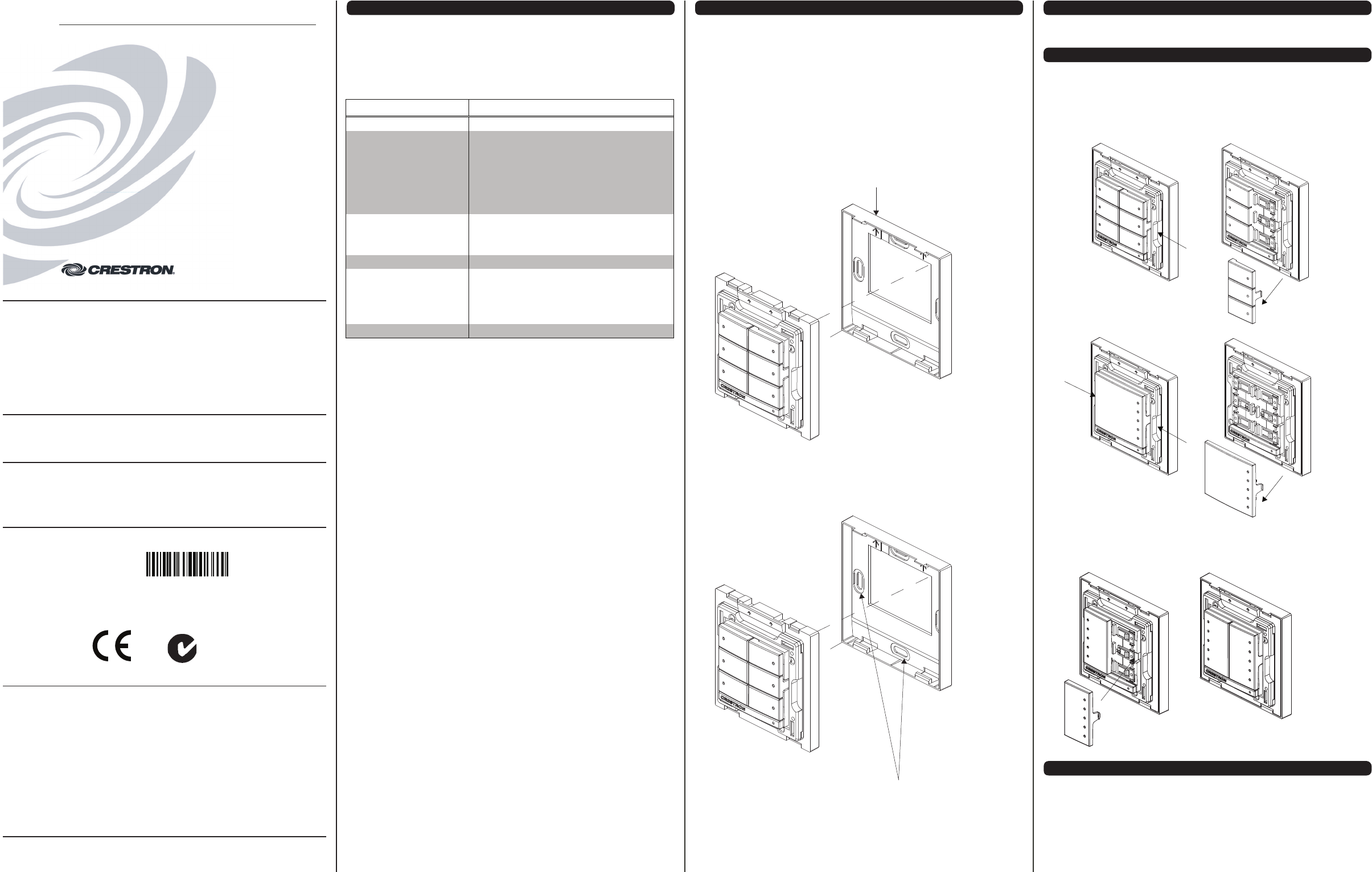
3. Insert the new button assemblies onto the device by pressing them into the device. It
might be necessary to squeeze the sides of the button assembly to allow for easier
assembly.
Install Button Assembly
CHANGE BUTTON ASSEMBLIES
Follow the procedure below if the button assemblies need to be changed or replaced.
1. Squeeze the sides of the button assembly near the center of the device or, for two or
more button assemblies, press on one side of the button assembly.
2. Remove the button assembly by carefully pulling the button assembly off of the device.
For two or more button assemblies, remove the second button in the same manner.
Refer to the illustrations that follow.
Remove Button Assembly
MOUNTING
The CLWI-KPLEX-BATT can be mounted using double-sided tape or mounting screws (not
supplied). Refer to the procedures below for mounting instructions.
Stick-On Surface Mounting
The CLWI-KPLEX-BATT can be mounted to the wall using double-sided tape. Refer to the
following procedure for instructions.
1. Remove the release liner on one side of the double-sided tape.
2. Carefully lay the exposed adhesive side of the double-sided tape flat across the rear
surface of the keypad and gently press down on the double-sided tape to ensure
adhesion.
3. Remove the second release liner on the double-sided tape.
4. Firmly press the rear surface of the keypad flat against the wall to ensure adhesion.
Stick-On Surface Mounting
Permanent Mounting
The CLWI-KPLEX-BATT can be mounted to a round or square electrical box using four
mounting screws (not supplied) or directly to a flat surface using screws appropriate for the
mounting scenario (not supplied). Refer to the following illustration for a typical permanent
mount scenario.
Permanent Surface Mounting
Secure to the electrical box or flat
surface using screws appropriate for
the mounting scenario (not supplied).
Secure to the mounting surface
using the double-sided tape
attached to the rear of the device.
SPECIFICATION DETAILS
Power Requirements 3 Volts ac, CR2450 battery
Wireless
RF Transceiver 2-way RF, 2.4 GHz ISM Channels 11 to 26
(2400 to 2483.5 MHz), IEEE 802.15.4 compliant
Range (Typical) Subject to site-specific conditions;
Range is increased by adding additional devices or
wireless expander
Gateway Requires an infiNET EX gateway (sold separately)
Environmental
Temperature 0° to 40° C (32° to 104° F)
Humidity 10% to 90% RH (non-condensing)
Enclosure Mounts to surface, requires faceplate (not included)
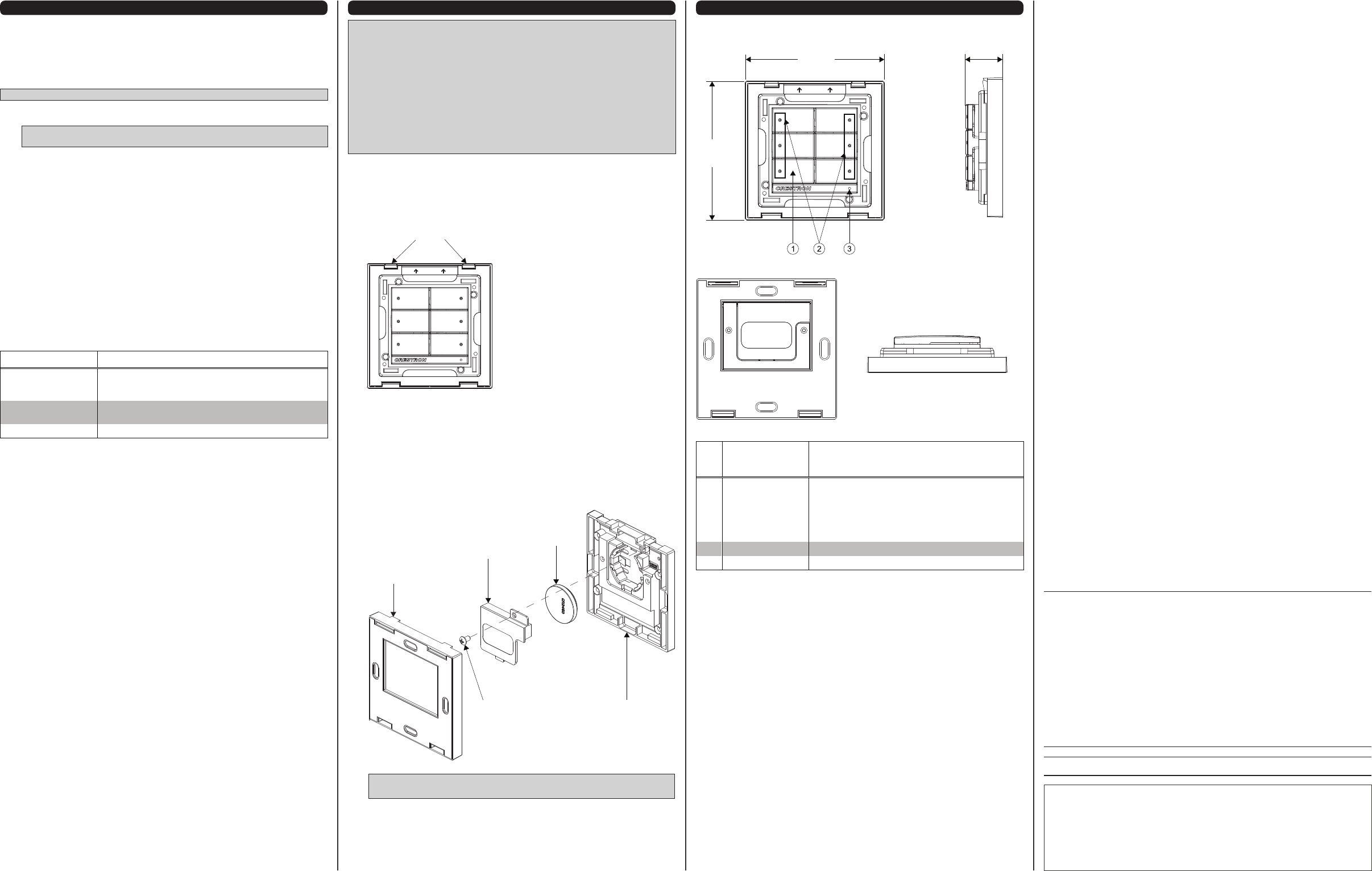
Dimensions
Height 73 mm (2.85 in)
Width 73 mm (2.85 in)
Depth 20 mm (0.76 in) including front face with buttons
Weight 55 g (2 oz)
Regulatory Compliance (Continued)
Industry Canada (IC) Compliance Statement
This device complies with Industry Canada license-exempt RSS standard(s). Operation is subject to the following two
conditions: (1) this device may not cause interference and (2) this device must accept any interference, including interference
that may cause undesired operation of the device.
Under Industry Canada regulations, this radio transmitter may only operate using an antenna of a type and maximum (or lesser)
gain approved for the transmitter by Industry Canada. To reduce potential radio interference to other users, the antenna type
and its gain should be so chosen that the equivalent isotropically radiated power (e.i.r.p.) is not more than that necessary for
successful communication.
Industrie Canada (IC) Déclaration de conformité
Le présent appareil est conforme aux CNR d'Industrie Canada applicables aux appareils radio exempts de licence.
L'exploitation est autorisée aux deux conditions suivantes : (1) l'appareil ne doit pas produire de brouillage, et (2) l'utilisateur de
l'appareil doit accepter tout brouillage radioélectrique subi, même si le brouillage est susceptible d'en compromettre le
fonctionnement.
Conformément à la réglementation d'Industrie Canada, le présent émetteur radio peut fonctionner avec une antenne d'un type
et d'un gain maximal (ou inférieur) approuvé pour l'émetteur par Industrie Canada. Dans le but de réduire les risques de
brouillage radioélectrique à l'intention des autres utilisateurs, il faut choisir le type d'antenne et son gain de sorte que la
puissance isotrope rayonnée équivalente (p.i.r.e.) ne dépasse pas l'intensité nécessaire à l'établissement d'une communication
satisfaisante.
To satisfy RF exposure requirements, this device and its antenna must operate with a separation distance of at least 20
centimeters from all persons and must not be colocated or operating in conjunction with any other antenna or transmitter.
WIRELESS COMMUNICATIONS
The device connects to the Crestron network via the infiNET EX communications protocol.
Use the procedures outlined below to join or leave an infiNET EX network and to verify
communications between the device and the control system.
Joining an infiNET EX Network
Before a device can be used in a lighting system, it must first join an infiNET EX network by
being acquired by an infiNET EX gateway.
NOTE: A device can be acquired by only one gateway.
1. Put the infiNET EX gateway into Acquire mode from the unit itself or from Crestron
Toolbox, as described in its manual at www.crestron.com/manuals.
NOTE: In an environment where multiple gateways are installed, only one gateway
should be in Acquire mode at any time.
2. Place the device into Acquire mode by doing the following:
a. Tap the setup button three times then press and hold it down (tap-tap-tap-
press+hold) until all LEDs on the device flash once (this can take up to 10 seconds).
b. Release the button to start the acquire process. The top two LEDs blink slowly to
show that the device is actively scanning the infiNET EX network.
• The top two LEDs turn on for 5 seconds to show that the device has been
successfully acquired to the infiNET EX network.
• The top two LEDs blink fast to indicate that the device was not successfully
acquired by the infiNET EX network. Tap the setup button to acknowledge failure
to acquire the infiNET EX network. Ensure gateway is in Acquire mode and within
range before attempting the acquire process again.
Leaving an infiNET EX Network
To leave an infiNET EX network put the device into Acquire mode, as described in “Joining
an infiNET EX Network” above, when no gateway is in Acquire mode.
Verifying Communications Status
To check the communication status of the device tap the setup button three times then press
and hold it down (tap-tap-tap-press+hold) for 2 seconds. The top two LEDs blink to indicate
the communication status. Refer to the following table for details.
REPLACE BATTERY
WARNING: Refer to the following warnings before changing the batteries.
• Do not ingest batteries, chemical burn hazard.
• This product contains coin cell batteries. If a coin cell battery is swallowed, it can
cause severe internal burns in just 2 hours and can lead to death.
• Keep new and used batteries away from children. If the battery compartment does not
close securely, stop using the product and keep it away from children.
• If you think batteries have been swallowed or placed inside any part of the body, seek
immediate medical attention.
CAUTION: The battery used in this device may present a risk of fire or chemical burn if
mistreated. Do not recharge, disassemble, heat above 100° C (212° F), or incinerate.
Replace battery with CR2450 only. Use of another battery may present a risk of fire or
explosion.
Follow the instructions below to replace the battery in the CLWI-KPLEX-BATT. Refer to the
illustration that follows for details.
1. Remove the faceplate.
2. Remove the CLWI-KPLEX-BATT from the wall mount adapter using a flat head screw
driver to gently separate the top of the device from the wall mount adapter.
Remove from Wall Mount Adapter
3. Using a Phillips head screwdriver, remove the screw on the back of the device that
secures the battery cover.
4. Remove the battery from the battery holder.
5. Replace with a new CR2450 battery.
6. Return the battery cover to its original position and secure it with the screw removed in
step 3.
7. To mount the CLWI-KPLEX-BATT, push the bottom of the device into the wall mount
adapter, followed by the top of the device. The wall mount adapter clicks once the
device is secured.
Return to Wall Mount Adapter
NOTE: Dispose of batteries promptly. Keep away from children. Do not
disassemble and do not dispose of in fire.
Insert Screwdriver
Here
CLWI-KPLEX-BATT Physical View (Rear and Side Views)
Connectors, Controls, and Indicators
PHYSICAL DESCRIPTION
This section provides information on the controls and indicators available on the
CLWI-KPLEX-BATT.
CLWI-KPLEX-BATT Physical View (Front and Side Views)
LED DISPLAY COMMUNICATIONS STATUS
Turns on (up to 5
seconds) when button is
released
Device communicating with control system
Blinks twice Device previously joined to network but not communicating
with the gateway
Blinks once Device not joined to the network
# CONNECTORS,
CONTROLS, AND
INDICATORS
DESCRIPTION
1 Buttons Configurable for one rocker (up/down), or any
combination of up to two small rockers or two 3-button
pads;
Default button arrangement:
CLWI-KPLEX-BATT: Two 3-button pads
Maximum layout contains six buttons
2 LED Indicator LED lights to indicate button press
3 Setup Button Allows setup and configuration of the device
The specific patents that cover Crestron products are listed at patents.crestron.com.
Crestron, the Crestron logo, Crestron Toolbox, Crestron Studio, and infiNET EX are either trademarks or
registered trademarks of Crestron Electronics, Inc. in the United States and/or other countries. Other
trademarks, registered trademarks, and trade names may be used in this document to refer to either the
entities claiming the marks and names or their products. Crestron disclaims any proprietary interest in the
marks and names of others. Crestron is not responsible for errors in typography or photography.
This document was written by the Technical Publications department at Crestron.
©2013 Crestron Electronics, Inc.
Return and Warranty Policies
Merchandise Returns / Repair Service
1. No merchandise may be returned for credit, exchange, or service without prior
authorization from Crestron. To obtain warranty service for Crestron products, contact an
authorized Crestron dealer. Only authorized Crestron dealers may contact the factory and
request an RMA (Return Merchandise Authorization) number. Enclose a note specifying
the nature of the problem, name and phone number of contact person, RMA number, and
return address.
2. Products may be returned for credit, exchange, or service with a Crestron Return
Merchandise Authorization (RMA) number. Authorized returns must be shipped freight
prepaid to Crestron, 6 Volvo Drive, Rockleigh, N.J. or its authorized subsidiaries, with RMA
number clearly marked on the outside of all cartons. Shipments arriving freight collect or
without an RMA number shall be subject to refusal. Crestron reserves the right in its sole
and absolute discretion to charge a 15% restocking fee plus shipping costs on any
products returned with an RMA.
3. Return freight charges following repair of items under warranty shall be paid by Crestron,
shipping by standard ground carrier. In the event repairs are found to be non-warranty,
return freight costs shall be paid by the purchaser.
Crestron Limited Warranty
Crestron Electronics, Inc. warrants its products to be free from manufacturing defects in materials
and workmanship under normal use for a period of three (3) years from the date of purchase from
Crestron, with the following exceptions: disk drives and any other moving or rotating mechanical
parts, pan/tilt heads and power supplies are covered for a period of one (1) year; touch screen
display and overlay components are covered for 90 days; batteries and incandescent lamps are
not covered.
This warranty extends to products purchased directly from Crestron or an authorized Crestron
dealer. Purchasers should inquire of the dealer regarding the nature and extent of the dealer's
warranty, if any.
Crestron shall not be liable to honor the terms of this warranty if the product has been used in any
application other than that for which it was intended or if it has been subjected to misuse,
accidental damage, modification, or improper installation procedures. Furthermore, this warranty
does not cover any product that has had the serial number altered, defaced, or removed.
This warranty shall be the sole and exclusive remedy to the original purchaser. In no event shall
Crestron be liable for incidental or consequential damages of any kind (property or economic
damages inclusive) arising from the sale or use of this equipment. Crestron is not liable for any
claim made by a third party or made by the purchaser for a third party.
Crestron shall, at its option, repair or replace any product found defective, without charge for parts
or labor. Repaired or replaced equipment and parts supplied under this warranty shall be covered
only by the unexpired portion of the warranty.
Except as expressly set forth in this warranty, Crestron makes no other warranties, expressed or
implied, nor authorizes any other party to offer any warranty, including any implied warranties of
merchantability or fitness for a particular purpose. Any implied warranties that may be imposed by
law are limited to the terms of this limited warranty. This warranty statement supersedes all
previous warranties.
73 mm
(2.85 in)
73 mm
(2.85 in)
20 mm
(0.76 in)
Screw CLWI-KPLEX-BATT
Wall Mount
Adapter
Battery Cover
Battery