Crestron Electronics CWD1015 2-Way RF Module with MHF User Manual CWD1015
Crestron Electronics Inc 2-Way RF Module with MHF CWD1015
Users Manual

Crestron CWD1015
Two-Way RF Transceiver Module
Operations Guide

This document was prepared and written by the Technical Documentation department at:
Crestron Electronics, Inc.
15 Volvo Drive
Rockleigh, NJ 07647
1-888-CRESTRON
All brand names, product names and trademarks are the property of their respective owners.
©2007 Crestron Electronics, Inc.

Crestron CWD1015 Two-Way RF Transceiver Module
Operations Guide - DOC. 6659 Contents • i
Contents
Two-Way RF Transceiver Module: CWD1015 ............................................. 1
Introduction................................................................................................................................1
Functions and Features ................................................................................................1
Specifications ..............................................................................................................2
Physical Description....................................................................................................2
Industry Compliance....................................................................................................4
Setup ..........................................................................................................................................6
Hardware Hookup........................................................................................................6
End Product Labeling ..................................................................................................6
Documentation ............................................................................................................6

Crestron CWD1015 Two-Way RF Transceiver Module
Operations Guide - DOC. 6659 Two-Way RF Transceiver Module: CWD1015 • 1
•
Two-way RF transceiver
− 2.4 GHz frequency band, IEEE 802.15.4 specification
− Range from 3 feet to 100 ft.
− Operates on one of sixteen available channels to establish optimal
signal quality
Two-Way RF Transceiver Module:
CWD1015
Introduction Functions and Features
The CWD1015 (hereafter referred to as “module”) is a two-way radio frequency
(RF) module that utilizes the 2.4 GHz frequency band to communicate with other
devices.
The module operates according to the IEEE 802.15.4 specification and can be
configured to minimize the possibility of interference with other devices.
The module receives RF signals from one or more Crestron devices and can transmit
these signals over the air or over a cable run for further processing (depending on the
application).
Functional Summary
The transceiver uses a 100 milliwatt signal that can travel up to approximately 100
feet indoors. The range is dependent on the construction of the building,
obstructions, and RF interference from other devices. The location of the module and
the orientation of its antenna are also important factors in determining RF
performance.
Two-Way RF Transceiver Module Crestron CWD1015
2 • Two-Way RF Transceiver Module: CWD1015 Operations Guide - DOC. 6659
Specifications
The table below is a summary of specifications for the CWD1015.
Specifications of the CWD1015
SPECIFICATION DETAILS
Power Requirements 0.75 Watts (3.3VDC @ 0.250A)
Operating Frequency 2400 MHz to 2483.6 MHz (802.15.4 compliant)
Operating Ranges¹
Minimum Distance
Maximum Distance Indoors
(without repeater device)
3 ft
100 ft
Available Channels 16 (numbered 11 through 26 per 802.15.4)
RF Output Power 100 mW
Serial Communications SPI, TTL Level
Antenna Connector U.FL/MMC
Dimensions Width: 1.50 in (3.81 cm)
Height: 2.50 in (6.35 cm)
Depth: 0.36 in (0.91 cm)
1. The location of the module and the orientation of the antenna are important factors in the RF
performance. With the unit located outside of any metal enclosures, the antenna is adjusted to
achieve the best range. The range is dependent on its placement and the building in which it is used.
The construction of the building, obstructions, and RF interference from other devices are factors
determining the effective range of the unit. To prevent unit-to-unit RF interference, multiple
modules operating at the same frequencies should not be installed within 3-5 feet of each other.
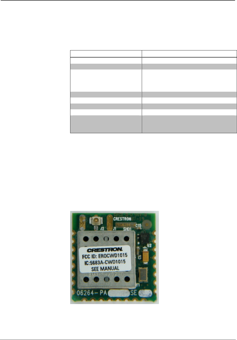
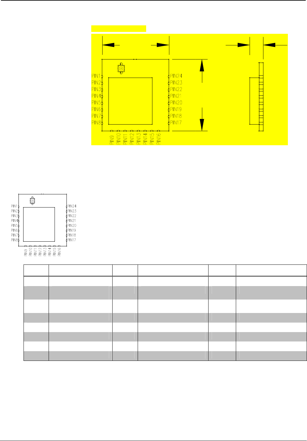
Physical Description
The module, shown below, consists of various components attached to a printed
circuit board. A SMA non-standard female antenna port is located at edge of the
circuit board for attaching a dipole antenna while 24 solder points line the perimeter
of the printed circuit board for the application-specific installation.
Physical View of CWD1015
Crestron CWD1015 Two-Way RF Transceiver Module
Operations Guide - DOC. 6659 Two-Way RF Transceiver Module: CWD1015 • 3
CWD1015 Detail Views
(2.54 cm)
1.00 in
1.08 in
(2.74 cm)
0.20 in
(0.51 cm)
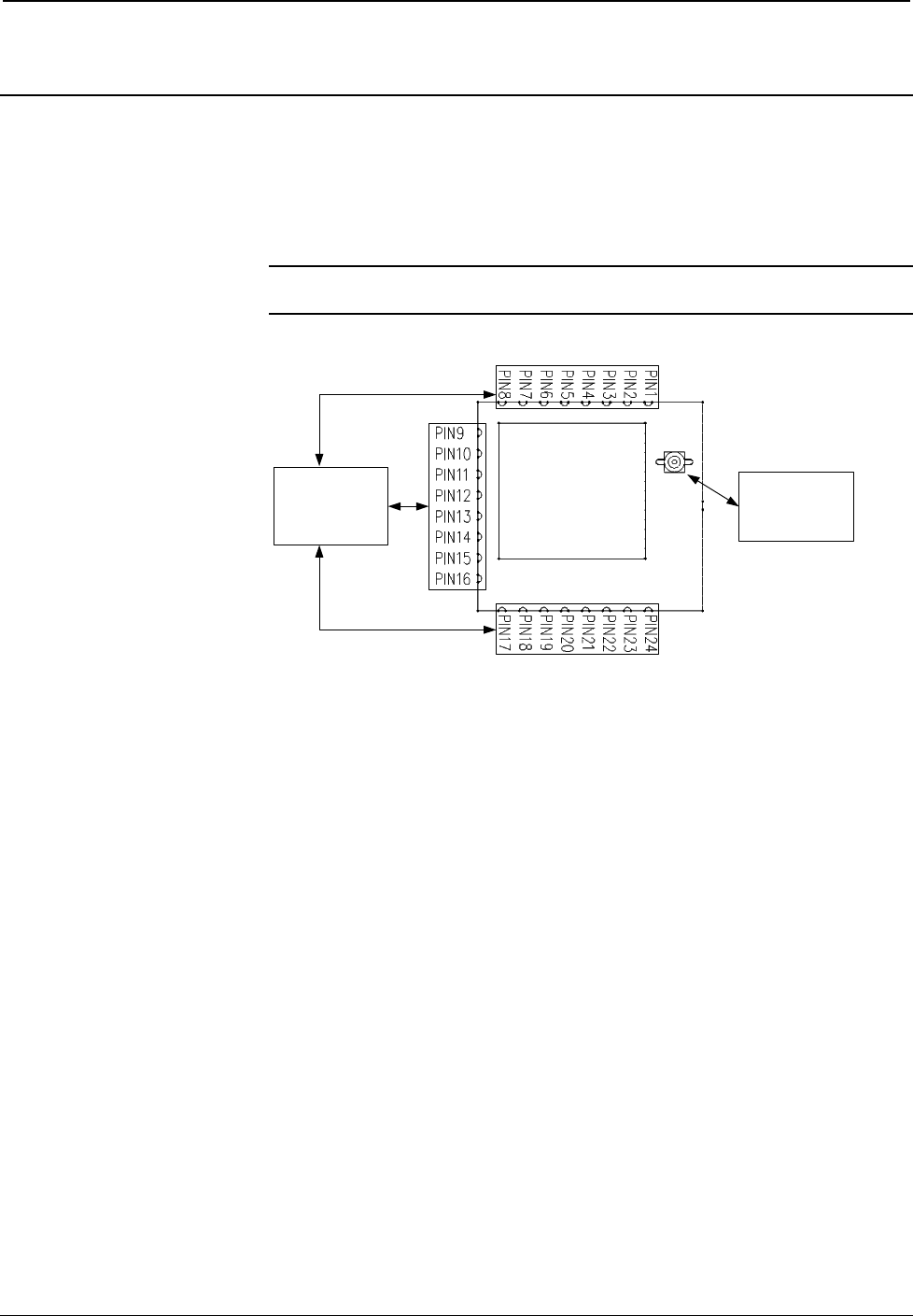
Ports
The module contains 24 solder points and one antenna port. Refer to the diagrams
and descriptions that follow.
Power/I-O
Twenty-four solder points provide power to the module as well as serial
communications between the module and wired devices. Refer to the following table
for pin assignments of the module interface connector.
Power/I-O Pinout Signals
Pin # Signal Pin # Signal Pin # Signal
1 GND 9 Output Amplifier Enable 17 IRQ (active low)
2 Receive Enable
(active low) 10 RX/TX Enable 18 Reserved (No Connection)
3 Transmit Enable
(active low) 11 Attention (active low) 19 Reserved (No Connection)
4 Reserved 12 Reserved (No Connection) 20 Reserved (No Connection)
5 Reserved 13 SPI CLK 21 GND
6 Reserved 14 SPI MOSI 22 GND
7 Reserved 15 SPI MISO 23 VCC 3.3V
8 Reset (active low) 16 SPI_CE (active low) 24 GND

Two-Way RF Transceiver Module Crestron CWD1015
4 • Two-Way RF Transceiver Module: CWD1015 Operations Guide - DOC. 6659
Antenna
This U.FL/MMC antenna port is located at edge of the circuit board for attaching an
antenna.
APPROVED ANTENNAS:
The CWD1015 antenna interface has a unique coupling designed to ensure that no
antenna other than the one supplied shall be used with the device. Replacement
antennas may be purchased from Crestron according to the following description:
Part Number: Crestron #4504627
Description: ANTENNA, PCB ASSY 2.4 - 2.5 Ghz U.FL connect .
Industry Compliance
Labeling Requirements
If the FCC ID on the CWD1015 is not visible when the module is installed inside
another device, then the outside of the device into which the module is installed must
also display a label referring to the enclosed module. This exterior label can use
wording such as the following: “Contains Transmitter Module FCC ID:
EROCWD1015” or “Contains FCC ID: EROCWD1015.” Any similar wording that
expresses the same meaning may be used.
Compliance Statement (Part 15.19 )
This device complies with Part 15 of the FCC Rules. Operation is subject to the
following two conditions:
1. This device may not cause harmful interference, and
2. This device must accept any interference received, including interference
that may cause undesired operation.
Warning (Part 15.21 )
Changes or modifications not expressly approved by the party responsible for
compliance could void the user’s authority to operate the equipment.
RF Exposure (OET Bulletin 65 )
To comply with FCC RF exposure requirements for mobile transmitting devices, this
transmitter should only be used or installed at locations where there is at least 20cm
separation distance between the antenna and all persons.
Industry Canada Statement
The term "IC" before the certification/registration number only signifies that the
Industry Canada technical specifications were met.
IC: 5683A-CWD1015
Section 7.1.5 of RSS-GEN
Operation is subject to the following two conditions:
1) this device may not cause interference, and
2) this device must accept any interference, including interference that may cause
undesired operation of the device.

Crestron CWD1015 Two-Way RF Transceiver Module
Operations Guide - DOC. 6659 Two-Way RF Transceiver Module: CWD1015 • 5
Section 7.1.4 of RSS-GEN
This device has been designed to operate with the antenna(s) listed below, and
having a maximum gain of 1.9 dBi. Antennas not included in this list or having a
gain greater than 1.9 dBi are strictly prohibited for use with this device. The
required antenna impedance is 50 ohms.
Part Number Crestron #4504627
Frequency 2.4-2.5 GHz
Polarization Linear
Operating temperature -40 to + 85 degC
Impedance 50 Ohm
Min Typ Max
Peak Gain 0.8dBi 1.2dBi 1.9dBi Frequency 2.4-2.5 GHz
Efficiency 70% 75% 79%
VSWR 1.0:1 1.5:1 1.9:1 Frequency 2.4-2.5 GHz
Section 7.1.5 of RSS-GEN
To reduce potential radio interference to other users, the antenna type and its gain
should be so chosen that the equivalent isotropically radiated power (e.i.r.p.) is not
more than that permitted for successful communication.
Antenna Requirements:
The module must be installed such that the antenna connector is accessible for direct
antenna connection in the final configuration. If any cable or antenna other than that
provided with the CWD1015 is used, then the FCC authorization is no longer
considered valid and the FCC ID cannot be used on the final product. In these
circumstances, the OEM integrator will be responsible for reevaluating the end
product (including the transmitter) and obtaining a separate FCC authorization.
FCC Radiation Exposure Statement:
This equipment complies with FCC radiation exposure limits set forth for an
uncontrolled environment. This equipment should be installed and operated with
minimum distance 20cm between the radiator & your body. This transmitter must
not be co-located or operating in conjunction with any other antenna or transmitter.
This device is intended only for OEM integrators under the following
conditions:
1. The antenna must be installed such that 20 cm is maintained between the
antenna and users, and
2. The transmitter module may not be co-located with any other transmitter or
antenna.
As long as the two conditions above are met, further transmitter test will not be
required. However, the OEM integrator is still responsible for testing their end-
product for any additional compliance requirements required with this module
installed (for example, digital device emissions, PC peripheral requirements, etc.).
IMPORTANT NOTE: In the event that these conditions cannot be met (for
example certain laptop configurations or co-location with another transmitter), then
the FCC authorization is no longer considered valid and the FCC ID cannot be used
on the final product. In these circumstances, the OEM integrator will be responsible
for reevaluating the end product (including the transmitter) and obtaining a separate
FCC authorization.
Two-Way RF Transceiver Module Crestron CWD1015
6 • Two-Way RF Transceiver Module: CWD1015 Operations Guide - DOC. 6659
Setup
Hardware Hookup
Refer to the hookup diagram below, which shows the connections made to the
module. Complete the connections in any order.
NOTE: To prevent unit-to-unit RF interference, multiple modules operating at the
same frequencies should not be installed within three to five feet of each other.
Hookup Connections for CWD1015
ANTENNA:
TRANSMITS
AND RECEIVES
RF SIGNALS
POWER-I/O:
PROVIDES
POWER AND
SYSTEM
INTERFACE
For more information on these connectors, refer to “Ports” on page 3.
End Product Labeling
The final end product must be labeled in a visible area with the following: “Contains
FCC ID: EROCWD1015 .
Documentation
The OEM integrator has to be aware not to provide information to the end user
regarding how to install or remove this RF module in the users manual of the end
product which integrate this module.
The users manual for OEM integrators must include the following information in a
prominent location
“IMPORTANT NOTE: To comply with FCC RF exposure
compliance requirements, the antenna used for this transmitter
must be installed to provide a separation distance of at least 20
cm from all persons and must not be co-located or operating in
conjunction with any other antenna or transmitter.”

Crestron CWD1015 Two-Way RF Transceiver Module
Operations Guide - DOC. 6659 Two-Way RF Transceiver Module: CWD1015 • 7
This page intentionally left blank

Crestron Electronics, Inc. Operations Guide - DOC. 6659
15 Volvo Drive Rockleigh, NJ 07647 01.08
Tel: 888.CRESTRON INTERNAL USE ONLY
Fax: 201.767.7576 Specifications subject to
www.crestron.com change without notice.