Crestron Electronics FANDELVEX Two-Way RF Transceiver User Manual CLC FANDELVEX W IO 7705B Preliminary 0 CS
Crestron Electronics Inc Two-Way RF Transceiver CLC FANDELVEX W IO 7705B Preliminary 0 CS
User Manual
Preliminary
CLC-FANDELVEX-W
inNET EX® Fan Controller
Installation Guide
Description
The Crestron® CLC-FANDELVEX-W is an inNET EX fan and light controller. The compact
design allows it to securely t in a fan canopy.
Refer to the following table for specications for the CLC-FANDELVEX-W.
Installation
WARNING: To avoid re, shock, or death, turn off the power at the circuit breaker or
fuse and test that the power is off before wiring!
WARNING: To reduce the risk of electric shock, install the CLC-FANDELVEX-W with an
isolating wall control or switch.
CAUTION: To reduce the risk of overheating and possible damage to other equipment,
do not install to control a receptacle.
NOTES: Observe the following points:
• Install and use this prodct in accordance with appropriate electrical codes and
regulations.
• A licensed electrician should install this product.
• Do not install in a damp or moist environment. This product is for indoor use only.
NOTE: Before using the CLC-FANDELVEX-W, ensure the device is using the latest
rmware. Check for the latest rmware for the CLC-FANDELVEX-W at
www . crestron . com / rmware. Firmware is loaded onto the device using Crestron
Toolbox™ software.
NOTE: Refer to the documentation for the fan for proper installation or disassembly and
reassembly.
NOTE: Using the fan’s hardware controls, set the fan to high speed and the lights to on.
NOTE: Remove any pre-installed fan remote controller before installing the
CLC-FANDELVEX.
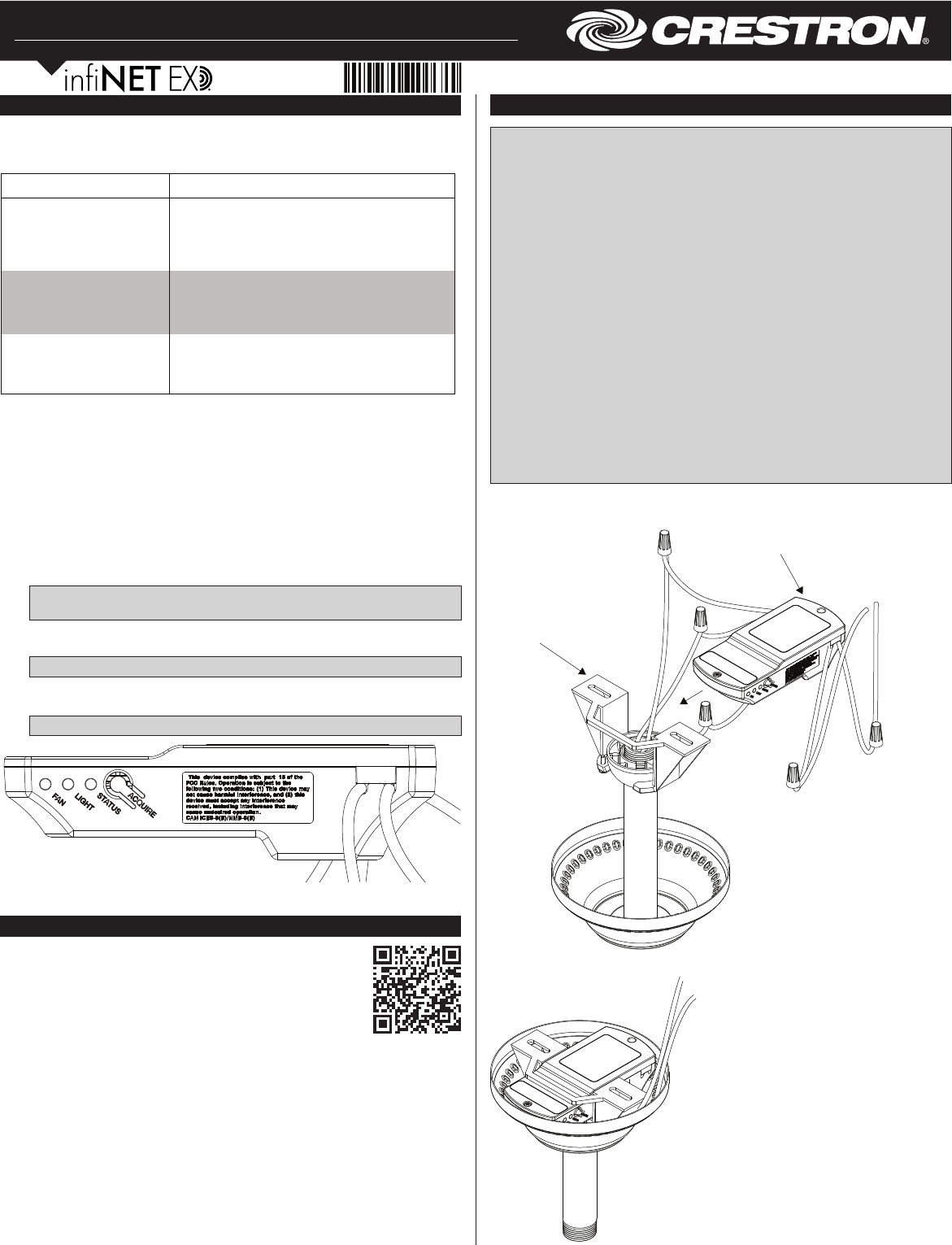
Install the CLC-FANDELVEX-W after all connections have been made. The
CLC-FANDELVEX-W can be inserted into most common fan canopies. Refer to the
following illustration for details.
Additional Resources
Visit the product page on the Crestron website (www.crestron.com)
for additional information and the latest rmware updates. Use a QR
reader application on your mobile device to scan the QR image.
To Junction Box
CLC-FANDELVEX-W
Ceiling Fan
Mounting
Bracket
To Junction Box
CLC-FANDELVEX-W Installed in Fan Canopy
The CLC-FANDELVEX-W has a multifunction ACQUIRE button and STATUS, LIGHT, and
FAN LEDs. Their functions are described below.
The ACQUIRE button:
• Allows the device to connect to the inNET EX network. Refer to the “Wireless
Communications” section for details.
• Press to toggle the dimming load between on and off.
• Press to exit Identify mode.
The STATUS LED:
• Illuminates green to indicate it is receiving power.
• Flashes green to indicate inNET EX acquire status.
• Flashes red to indicate error conditions.
NOTE: The green LED extinguishes after 1 minute. The red LED extinguishes
when the error is cleared.
The LIGHT LED:
• Illuminates to indicate that a command was received to turn on the light.
NOTE: The LIGHT LED extinguishes after 1 minute.
The FAN LED:
• Illuminates to indicate that a command was received to turn on the fan.
NOTE: The FAN LED extinguishes after 1 minute.
SPECIFICATION DETAILS
Current Ratings
Fan Load 120 Vac, 0.8 A, 60 Hz
Light Load 120 Vac, 200 W, 60 Hz
(100 W Max for CFL or LED Loads)
Load Types Dimmed incandescent, CFL, LED, tungsten,
electronic low voltage
NOTE: Do not connect to magnetic low-voltage
type loads.
Environmental
Temperature 32° to 104 °F (0° to 40 °C)
Humidity 10% to 90% RH (noncondensing)
Preliminary
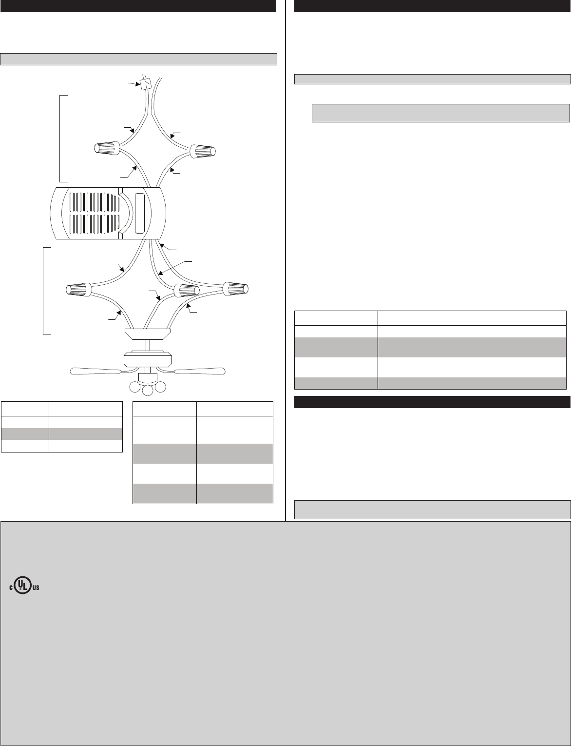
Wiring
The module has ying leads for power and control. Power enters the CLC-FANDELVEX-W
and passes fan control and light power to the fan. The CLC-FANDELVEX-W has one black
(hot) and one white (neutral) power input. It also has a red (fan), blue (light), and white
(neutral) output for control.
NOTE: Refer to the documentation for the fan to ensure proper fan wiring.
Wiring the CLC-FANDELVEX-W
Power and
Control
Output
Power
Input
AC 110 V 60 Hz
Wall Switch
White
Black
White (Neutral)
Black (Hot)
Red (Fan Power)
Blue (Light Power)
Blue Black (Motor)
White
White
(Neutral)
Regulatory Compliance
This product is Listed to applicable UL® Standards and requirements by Underwriters Laboratories
Inc.
Conformité Reglementaire
Ce produit est homologué selon les normes et les exigences UL applicables par Underwriters
Laboratories Inc.
Federal Communications Commission (FCC) Compliance Statement
This device complies with part 15 of the FCC Rules. Operation is subject to the following two
conditions: (1) This device may not cause harmful interference, and (2) this device must accept any
interference received, including interference that may cause undesired operation.
CAUTION: Changes or modications not expressly approved by the manufacturer responsible for
compliance could void the user’s authority to operate the equipment.
NOTE: This equipment has been tested and found to comply with the limits for a Class B digital
device, pursuant to part 15 of the FCC Rules. These limits are designed to provide reasonable
protection against harmful interference when the equipment is operated in a commercial environment.
This equipment generates, uses, and can radiate radio frequency energy and, if not installed and used
in accordance with the instruction manual, may cause harmful interference to radio communications.
Operation of this equipment in a residential area is likely to cause harmful interference in which case
the user will be required to correct the interference at his own expense.
Industry Canada (IC) Compliance Statement
CAN ICES-3(B)/NMB-3(B)
This equipment should be installed and operated with a minimum distance 20cm between the radiator
and your body Cet équipement doit être installé et utilisé à une distance minimale de 20 cm entre le
radiateur et votre corps.
Wireless Communications
The device connects to the Crestron network via the inNET EX communications protocol. Use
the procedures outlined below to join or leave an inNET EX network and to verify
communications between the device and the control system.
Joining an inNET EX Network
Before a device can be used in a lighting system, it must rst join an inNET EX network. To join
an inNET EX network, the device must be acquired by an inNET EX gateway.
NOTE: A device can be acquired by only one gateway.
1. Put the inNET EX gateway into Acquire mode from the unit itself or from Crestron
Toolbox. Refer to the gateway’s manual at www.crestron.com/manuals for details.
NOTE: In an environment where multiple gateways are installed, only one gateway
should be in Acquire mode at any time.
2. Put the device into Acquire mode.
a. Tap the ACQUIRE button three times and then press and hold it down
(tap-tap-tap-press+hold) until the green STATUS LED on the device blinks once (this
can take up to 10 seconds).
b. Release the button to start the acquire process. The green STATUS LED blinks slowly to
show that the device is actively scanning the inNET EX network.
• The green STATUS LED turns on for 5 seconds to show that the device has been
successfully acquired by the infiNET EX network.
• The green STATUS LED blinks fast to indicate that the device was not successfully
acquired by the infiNET EX network. Tap the ACQUIRE button to acknowledge the
failure. Ensure the gateway is in Acquire mode and within range before attempting
the acquire process again.
3. Once all devices have been acquired, take the gateway out of Acquire mode. Refer to the
gateway’s manual for details.
Leaving an inNET EX Network
To leave an inNET EX network, put the device into Acquire mode, as described in “Joining an
inNET EX Network” above, when no gateway is in Acquire mode.
Verifying Communications Status
To check the communications status of the device, tap the ACQUIRE button three times and then
press and hold it down (tap-tap-tap-press+hold) for up to 2 seconds. The green STATUS LED
blinks to indicate the communications status. Refer to the following table for details.
Crestron Electronics, Inc. Installation Guide - DOC. 7705C
15 Volvo Drive Rockleigh, NJ 07647 (2045179)
Tel: 888.CRESTRON 01.18
Fax: 201.767.7576 Specications subject to
www.crestron.com change without notice.
This device complies with Industry Canada license-exempt RSS standard(s). Operation is subject to
the following two conditions: (1) this device may not cause interference, and (2) this device must
accept any interference, including interference that may cause undesired operation of the device.
Le présent appareil est conforme aux CNR d'Industrie Canada applicables aux appareils radio
exempts de licence. L'exploitation est autorisée aux deux conditions suivantes : (1) l'appareil ne doit
pas produire de brouillage, et (2) l'utilisateur de l'appareil doit accepter tout brouillage radioélectrique
subi, même si le brouillage est susceptible d'en compromettre le fonctionnement.
The product warranty can be found at www.crestron.com/warranty.
The specic patents that cover Crestron products are listed at patents.crestron.com.
Certain Crestron products contain open source software. For specic information, please visit
www.crestron.com/opensource.
Crestron, the Crestron logo, Crestron Toolbox, inNET EX, and the inNET EX logo are either
trademarks or registered trademarks of Crestron Electronics, Inc. in the United States and/or other
countries. UL and the UL logo are either trademarks or registered trademarks of Underwriters
Laboratories, Inc. in the United States and/or other countries. Other trademarks, registered
trademarks, and trade names may be used in this document to refer to either the entities claiming the
marks and names or their products. Crestron disclaims any proprietary interest in the marks and
names of others. Crestron is not responsible for errors in typography or photography.
This document was written by the Technical Publications department at Crestron.
©2016 Crestron Electronics, Inc.
MODULE WIRE CONNECTION
White Neutral wires to
the junction box
and fan
Black Connects to the
live wire.
Red Connects to the
fan motor wire.
Blue Connects to the
lights.
Error States
The LED blinks a pattern to indicate an error. The patterns listed below are described as
2-1 or 2-3. For a 2-1 error, an overcurrent condition, the LED blinks twice, pauses for 1
second, blinks once, pauses for two seconds, and then repeats until the error is
corrected. During an overcurrent condition, the lights will turn off. Sending a new light
level corrects the overcurrent condition.
For a 2-3 error, an overtemperature error, the LED blinks twice, pauses for 1 second,
blinks three times, pauses for two seconds, and then repeats until the error is corrected.
During an overtemperature condition, the light and fan will turn off. During an
overtemperature error, requests to turn on the load or fan are ignored. The error clears
when the device cools.
NOTE: The overtemperature error is not saved in nonvolatile memory and is cleared
when power is cycled.
FAN WIRE TYPICAL COLOR
Fan Black
Lights Blue
Neutral White
LED COMMUNICATIONS STATUS
Turns on for 5 seconds The device is communicating with the control system.
Blinks three times The device is communicating with the gateway, but the
gateway is not communicating with the control system.
Blinks twice The device was previously joined to the network but is
not communicating with the gateway.
Blinks once The device is not joined to the network.