Crestron Electronics STX-1550C SMARTOUCH RF TOUCHPANEL User Manual Stx 155c
Crestron Electronics Inc SMARTOUCH RF TOUCHPANEL Stx 155c
UserManual.wiki
>
Crestron Electronics
>
STX 1550C User Manual
Manual
Navigation menu
Upload a User Manual
Namespaces
Wiki Guide
HTML
PDF
Info
Views
User Manual
Discussion / Help
Navigation
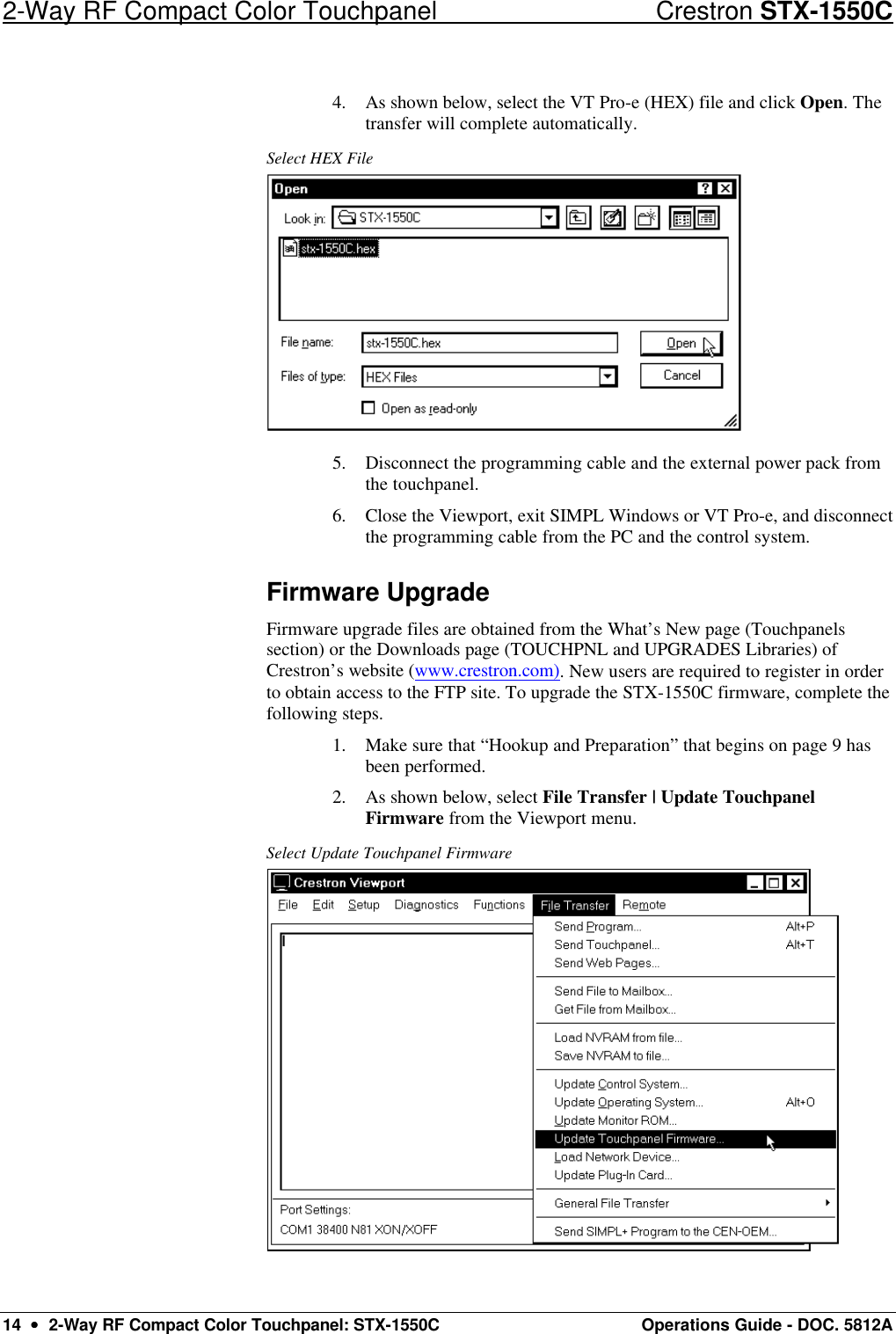
![Crestron STX-1550C 2-Way RF Compact Color Touchpanel Operations Guide - DOC. 5812A 2-Way RF Compact Color Touchpanel: STX-1550C •• 15 3. As shown below, select the NET ID of the STX-1550C and then click OK. “Select Network ID” Dialog Box NOTE: Firmware upgrades for touchpanels contain two files, xc[version]a file and xc[version]b file. When selecting a firmware file, select the a file which will automatically execute the b file. 4. As shown below, select the firmware (CSF) file and click Open. The transfer will complete automatically. Select CSF File 5. Disconnect the programming cable and the external power pack from the touchpanel. NOTE: When the firmware of the STX-1550C is upgraded, the associated STRFGWX(s) must also be upgraded. The units will not function properly if not upgraded with compatible firmware. 6. If the STRFGWX firmware upgrade HAS been completed, close the Viewport, exit SIMPL Windows or VT Pro-e, and disconnect the programming cable from the PC and the control system. If NOT completed, perform the STRFGWX firmware upgrade utilizing the firmware (UPG) file included with the download. Refer to the latest revision of the Operations Guide (Doc. 5811) for the STRFGWX for the firmware upgrade procedure. The latest version of the Operations Guide can be obtained from the Downloads page (MANUAL Library) of Crestron’s website (www.crestron.com). New users are required to register in order to obtain access to the FTP site.](https://usermanual.wiki/Crestron-Electronics/STX-1550C/User-Guide-175765-Page-19.png)
![Crestron STX-1550C 2-Way RF Compact Color Touchpanel Operations Guide - DOC. 5812A 2-Way RF Compact Color Touchpanel: STX-1550C •• 23 Further Inquiries If after reviewing this Operations Guide, you cannot locate specific information or have questions, please take advantage of Crestron's award winning customer service team by calling: • In the US and Canada, call Crestron’s corporate headquarters at 1-888-Crestron [1-888-273-7876] or 1-201-767-3400. • In Europe, call Crestron International at +32-15-50-99-50. • In Asia, call Crestron Asia at +852-2341-2016. • In Latin America, call Crestron America at +525-260-4336. For local support from exclusive Crestron factory-trained personnel call: • In Australia, call Soundcorp at +613-9488-1555. • In New Zealand, call Amber Technologies at +649-410-8382. Future Updates As Crestron improves functions, adds new features, and extends the capabilities of the STX-1550C, additional information and programming examples may be made available as manual updates. These updates are solely electronic and serve as intermediary supplements prior to the release of a complete technical documentation revision. The Downloads page of the Crestron website (www.crestron.com) directs the reader to the location and description of each update. Check the site periodically for update availability and its subjective value. Future Firmware Upgrades As Crestron improves functions, adds new features, and extends the capabilities of the STX-1550C, firmware upgrades may be made available. The upgrade files can be obtained from the What’s New page (Touchpanels section) or the Downloads page (TOUCHPNL and UPGRADES Libraries) of Crestron’s website. If the firmware of the STX-1550C is upgraded, the associated STRFGWX(s) must also be upgraded.](https://usermanual.wiki/Crestron-Electronics/STX-1550C/User-Guide-175765-Page-27.png)