Crestron Electronics ZUMKPBATT Two-Way RF Transceiver User Manual ZUMMESH KPBATT IG 7865B Preliminary 0 CS
Crestron Electronics Inc Two-Way RF Transceiver ZUMMESH KPBATT IG 7865B Preliminary 0 CS
User Manual
Preliminary
ZUMMESH-KPBATT
Zūm™ Battery-Powered Wireless Keypad
Installation Guide
SPECIFICATION DETAILS
Power Requirements CR2032 coin cell battery (included);
Provides at least 5 years of battery life
Enclosure 1-gang mountable;
Requires decorator-style faceplate (sold separately)
Environmental
Temperature 30° to 104 °F (0° to 40 °C)
Humidity 10% to 90% RH (noncondensing)
Dimensions
Height 4.25 in (108 mm)
Width 1.77 in (45 mm)
Depth 0.39 in (10 mm)
Description
The Crestron® ZUMMESH-KPBATT is an extremely slim battery-powered Zūm™ wireless
keypad with exible installation. The ZUMMESH-KPBATT is a versatile and easy-to-use
addition to the Zūm commercial lighting system. Powered by a battery and slim enough
to mount to the surface of a wall, the keypad’s streamlined design and out-of-the-box
functionality make it ideal for new or retrot installations.
Zūm keypads are preprogrammed. Install a keypad in a room with a Zūm J-Box Zone
Controller (sold separately), perform a series of button taps, and then use the keypad to
control the lights in the room – no programming required! Battery-powered Zūm
keypads are designed in the following four congurations:
• Single-Rocker Switch – Simple on and off lighting control
• Four-Button Keypad – Two buttons for on and off control and two scene recall
buttons
• Six-Button Keypad – Two buttons for on and off control, two buttons for dimming
up and dimming down, and two scene recall buttons
• Six-Button Keypad with Sensor Control - Two buttons for on and off control, two
buttons for dimming up and dimming down, one button for scene recall, and one
button for disabling the sensors in the room
A basic single-room Zūm system consists of Zūm mesh devices, i.e., dimmers, switches,
keypads, and sensors. The Zūm mesh devices in the room communicate directly with
each other without the need for a centralized gateway or processor.
To monitor or control the room from a centralized Crestron control system, use the
ZUMMESH-NETBRIDGE.
NOTE: The ZUMMESH-NETBRIDGE requires a J-box device to provide power.
For quick network setup, use the Zūm app on a smartphone or tablet.
Additional Resources
Visit the product page on the Crestron website (www.crestron.com)
for additional information. Use a QR reader application on your
mobile device to scan the QR image.
Battery
Prior to operation, remove the battery tab to turn on the keypad.
Installation
NOTES: Observe the following points.
• Codes: Install in accordance with all local and national electrical codes.
• Temperature: For use where temperatures are between 32° to 104 °F (0° to 40 °C).
• Electrical Boxes: Several devices can be installed in one electrical box (multigang).
For a smooth appearance, install one-piece multigang faceplates (not supplied).
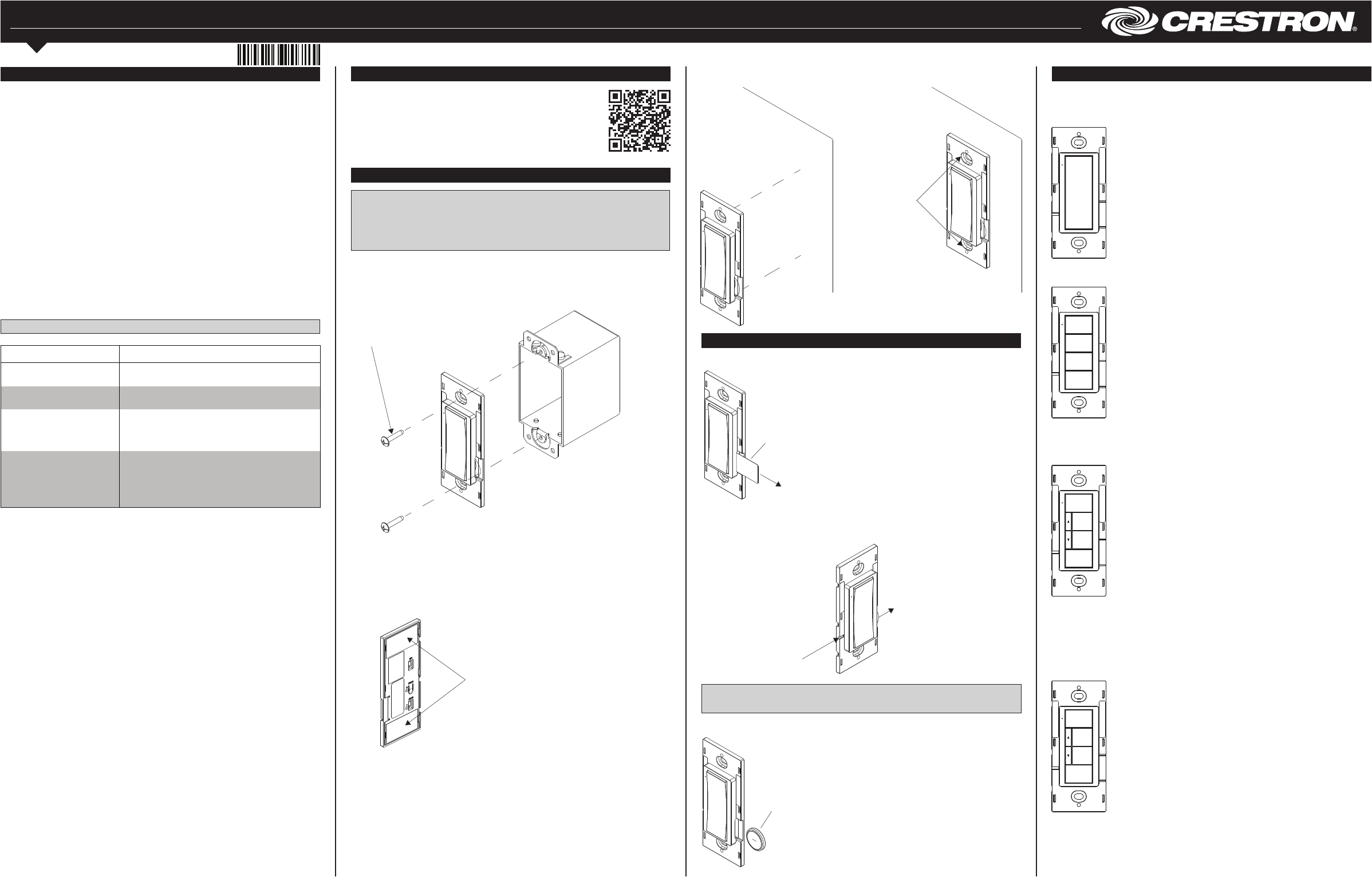
Mount the ZUMMESH-KPBATT to a single-gang box or directly to a at surface using
double-sided tape.
Single-Gang Box Mounting
Secure the ZUMMESH-KPBATT to a single-gang box using the two supplied screws.
Attach a decorator-style faceplate (not supplied).
Two screws are supplied
for mounting the keypad to
a back box.
Press rmly to ensure
proper adhesion.
Double-Sided Tape Mounting
Secure the ZUMMESH-KPBATT to a at, clean surface using the supplied double-sided
tape.
1. Clean the mounting surface with a light cleaning agent that does not leave a
residue.
2. Remove the backing of one piece of the double-sided tape and apply it to the back
of the keypad. Repeat for the other piece of double-sided tape.
Two pieces of tape are supplied
to mount the keypad without a
backbox.
3. Ensure that the keypad is vertical, and press it against the wall. Press rmly to
ensure that the keypad is properly secured to the wall.
Remove the battery tab prior
to operation.
Battery Replacement
To remove the battery, insert a pin or paper clip into the slot on the left side of the keypad.
The battery slides out of the opposite side of the keypad.
NOTE: The battery must be inserted properly.
NOTE: The keypad will not operate if the battery is inserted incorrectly.
To install a new battery, insert the battery into the battery slot. The — terminal faces
away from the wall.
To remove the battery,
insert a pin or paper clip
into the hole on the side.
Battery CR2032
(—) towards the front of the keypad
Default Button Functions
Crestron offers several ZUMMESH-KPBATT units.The ZUMMESH-KPBATT’s
functionality is based upon its button layout. By default, they control all loads in the
room. If linked to a dimmer, the ZUMMESH-KPBATT controls only its linked loads.
ON
SCENE 2
SCENE 3
OFF
ON
SCENE 2
SENSOR
DISABLE
OFF
ON
SCENE 2
SCENE 3
OFF
ZUMMESH-KP10ABATT Button Functions
Top Button
Press: Recalls Scene 1
Hold: Raises lights
Bottom Button
Press: Turns lights off
Hold: Lowers lights
ZUMMESH-KP10BBATT Button Functions
On
Press: Recalls Scene 1
Hold: Raises lights
SCENE 2
Press: Recalls Scene 2
Hold 5 Seconds: Saves Scene 2
SCENE 3
Press: Recalls Scene 3
Hold 5 Seconds: Saves Scene 3
OFF
Press: Turns lights off
Hold: Lowers lights
ZUMMESH-KP10CBATT Button Functions
On
Press: Recalls Scene 1
Hold: No action
SCENE 2
Press: Recalls Scene 2
Hold 5 Seconds: Saves Scene 2
SCENE 3
Press: Recalls Scene 3
Hold 5 Seconds: Saves Scene 3
OFF
Press: Turns lights off
Hold: Lowers lights
^
Hold: Raises lights
v
Hold: Lowers lights
ZUMMESH-KP10DBATT Button Functions
On
Press: Recalls Scene 1
Hold: No action
SCENE 2
Press: Recalls Scene 2
Hold 5 Seconds: Saves Scene 2
SENSOR DISABLE
Press: Recalls Scene 3
Hold 5 Seconds: Saves Scene 3
OFF
Press: Turns lights off
Hold: Lowers lights
^
Hold: Raises lights
v
Hold: Lowers lights
Preliminary
5s
10s
Step 2 - Adding Zūm Mesh Devices to the Room
Adding Zūm mesh devices to a room is quick and easy. Add devices to the room when
the room is in Joining mode. Joining mode is automatically enabled after a single-room
Zūm system is started (see Step 1a). Joining mode can also be enabled manually (see
Step 1b).
The LEDs on all ac-powered devices in the system blink when the system is in Joining
mode.
NOTE: A Zūm mesh device can belong to only one room.
NOTE: The Zūm mesh device used to create the room is already part of the network. It
does not need to be added to the network.
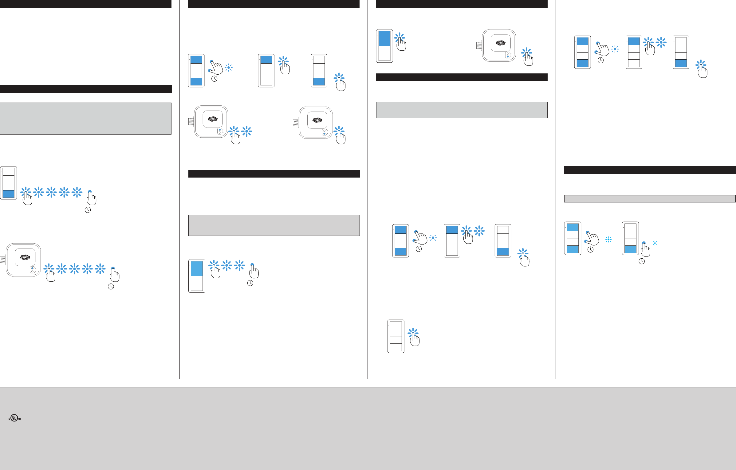
To add a keypad to the room, press the top button 3 times, and then press and hold the
top button for 2 seconds. If the device is not factory fresh, hold the button for 10
seconds. Release the button when the LED lights. The LED blinks slowly to indicate that
it is part of the room and that the room is still in Joining Mode.
While the device searches for a network to join, the LED ashes fast. When the device
successfully joins a network, the LED lights for 3 seconds. After joining the room, the
LED turns off. Unlike the LED on ac-powered devices, the LED on battery-powered
devices does not slow blink to show that it has joined the network.
2s or 10s
Step 3 - Finishing the Single-Room Zūm System
Press any button on a device that has already joined the network to end the setup
process (e.g., the top button of a keypad or the SETUP button of a J-box device that is
blinking its LED).
TEST
SETUP
Factory Reset
Press any button on a device that has already joined the network to end the setup
process (e.g., the top button of a keypad or the SETUP button of a J-box device that is
blinking its LED).
NOTE: New-in-box devices do not need to be factory reset before joining a system.
To factory reset a keypad, press and hold the top and bottom buttons for 5 seconds until
the LED lights, and then release both buttons. Then, press and hold the bottom button
for 10 seconds until the LED lights.
Basic Room Setup
A basic single-room Zūm system consists of Zūm mesh devices, i.e., dimmers, switches,
keypads, and sensors. The Zūm mesh devices in the room communicate directly with
each other without the need for a centralized gateway or processor.
To set up a new single-room Zūm system, do the following:
Step 1a: Create a new single-room Zūm system.
Step 2: Add Zūm mesh devices to the room.
Step 3: Finish creating the single-room Zūm system.
To modify an existing Zūm system, do the following:
Step 1b: Place the system in Joining mode.
Step 2: Add Zūm mesh devices to the room.
Step 3: Finish creating the single-room Zūm system.
Step 1a – Creating a Single-Room Zūm System
To create a new single-room Zūm system, rst form a new room.
NOTE: This can be performed on only one device in the room.
NOTE: The device that is used to create the room is automatically added to the room.
The device does not need to be added to the room.
NOTE: A room can be created only from an ac-powered device.
Start a New Single-Room System with a Keypad, Dimmer, or Switch
Press the bottom button 5 times, and then press and hold the bottom button for
2 seconds. If the device is not factory fresh, hold the button for 10 seconds. Release the
button when the LED lights. The LED illuminates for 3 seconds and then slowly ashes to
indicate that the room is in Joining mode and that other devices can join the room.
Start a Single-Room System with a J-Box Device
Press the SETUP button 5 times, and then press and hold the SETUP button for
2 seconds. If the device is not factory fresh, hold the button for 10 seconds. Release the
button when the LED lights. The LED illuminates for 3 seconds and then slowly ashes to
indicate that the room is in Joining mode and that other devices can join the room.
2s or 10s
TEST
SETUP
2s or 10s
Step 1b – Expanding an Existing Single-Room Zūm System
To allow other devices to join the room, place the single-room Zūm system into Joining
mode. Joining mode can be enabled from any ac-powered device or battery keypad that
is already part of the room.
Expand a Single-Room Zūm System Using a Keypad
To enter Joining mode, press and hold both the top and bottom buttons for 5 seconds,
wait for the LED to light, and then tap the top button once, and then the bottom button
once.
Pressing any button on a device that is part of the network takes the system out of
joining mode. Joining mode ends automatically after 4 minutes.
Expand a Single-Room Zūm System Using a J-Box Device
To enter Joining mode, tap the SETUP button 2 times, and then tap the TEST button.
TEST
SETUP
TEST
SETUP
5s
5s
Creating Scenes
Setting the scenes alters the default presets to allow customization of the brightness
levels when a button is pressed. Set scenes using the End-User Method, Manual
Method, or the Remote Method.
NOTE: Only load controllers bound to this keypad can be in the keypad’s scenes.
NOTE: All load controllers bound to this keypad must be in this keypad’s scenes.
End-User Method
The end-user method allows fast and efcient setting of the presets. The end-user
method is only applicable to SCENE 2 and SCENE 3. It cannot be used on 2-button
keypads, and cannot be used to save the ON (scene 1 preset) scene.
To customize presets, do the following:
1. Go to each load controller that is bound to the keypad and set the loads to the
desired brightness level for the scene.
2. Hold the SCENE 2 or SCENE 3 button for 5 seconds to save the current light levels
to the pressed button.
Manual Method
Use the Manual Method when each load controller is physically accessible.
To customize presets, do the following:
1. Using the keypad in the room, hold the top and bottom buttons simultaneously for
5 seconds until the LED ashes. Then press the top button 2 times, and then the
bottom button once.
• The keypad blinks its LED 2 times every 2 seconds.
• Load controllers that are linked with the keypad fast blink their LED.
2. Adjust the load levels.
• Using the dimmers, adjust all load levels in the room by pressing and holding the
top button to raise the light level or the bottom button to lower the light level.
• Using the switches, turn the loads on or off by pressing the top button to turn
the load on or the bottom button to turn the load off.
• Using the load controllers, press and hold the TEST button on the J-box device
to cycle-dim the load.
3. Using the keypad in the room, press the ON, SCENE 2, or SCENE 3 button that
should recall the current levels. This saves the levels to the scene.
4. Repeat steps 2 and 3 for all scenes.
5. Tap the bottom button on the keypad 3 times to exit scene setting.
ON
SCENE 2
SCENE 3
OFF
5s
Remote Method
Use the Remote Method when load controllers are not physically accessible.
To customize presets, do the following:
1. Using the keypad in the room, hold the top and bottom buttons simultaneously for
5 seconds until the LED ashes. Then press the top button 2 times, and then the
bottom button once.
3. Hold the bottom button for 3 seconds until one of the loads in the room begins to
ash. The load that is ashing is the "Selected" load.
4. Tap the bottom button to cycle through the loads until the desired load ashes. The
load ashes twice and then returns to its previous light level to indicate that it is
selected.
5. Adjust the brightness by holding the top button on the keypad to raise the light
level or holding the bottom button to lower the light level.
6. To save the light level to a scene, press the ON, SCENE 2, or SCENE 3 button.
7. Press the bottom button to select the next load controller that is bound to this
keypad. The load ashes twice and then returns to its previous light level to
indicate that it is selected.
8. Repeat steps 4 through 6 for additional load controllers until all load controllers and
all scenes are dened.
9. Tap the bottom button 3 times to exit.
This product is Listed to applicable UL® Standards and requirements tested by Underwriters
Laboratories Inc.
Ce produit est homologué selon les normes et les exigences UL applicables par Underwriters
Laboratories Inc.
Federal Communications Commission (FCC) Compliance Statement
This device complies with part 15 of the FCC Rules. Operation is subject to the following
conditions:(1) This device may not cause harmful interference and (2) this device must accept any
interference received, including interference that may cause undesired operation.
CAUTION: Changes or modications not expressly approved by the manufacturer responsible for
compliance could void the user’s authority to operate the equipment.
NOTE: This equipment has been tested and found to comply with the limits for a Class B digital
device, pursuant to part 15 of the FCC Rules. These limits are designed to provide reasonable
Crestron Electronics, Inc. Installation Guide - DOC. 7865B
15 Volvo Drive Rockleigh, NJ 07647 (2047761)
Tel: 888.CRESTRON 11.17
Fax: 201.767.7576 Specications subject to
www.crestron.com change without notice.
protection against harmful interference in a residential installation. This equipment generates, uses and
can radiate radio frequency energy and, if not installed and used in accordance with the instructions,
may cause harmful interference to radio communications. However, there is no guarantee that
interference will not occur in a particular installation. If this equipment does cause harmful interference
to radio or television reception, which can be determined by turning the equipment off and on, the user
is encouraged to try to correct the interference by one or more of the following measures:
• Reorient or relocate the receiving antenna.
• Increase the separation between the equipment and receiver.
• Connect the equipment into an outlet on a circuit different from that to which the receiver is
connected.
• Consult the dealer or an experienced radio/TV technician for help.
Industry Canada (IC) Compliance Statement
CAN ICES-3(B)/NMB-3(B)
This equipment should be installed and operated with a minimum distance 20cm between the radiator
and your body Cet équipement doit être installé et utilisé à une distance minimale de 20 cm entre le
radiateur et votre corps.
This device complies with Industry Canada license-exempt RSS standard(s). Operation is subject to the
following two conditions: (1) this device may not cause interference, and (2) this device must accept any
interference, including interference that may cause undesired operation of the device.
Le présent appareil est conforme aux CNR d'Industrie Canada applicables aux appareils radio exempts
de licence. L'exploitation est autorisée aux deux conditions suivantes : (1) l'appareil ne doit pas produire
de brouillage, et (2) l'utilisateur de l'appareil doit accepter tout brouillage radioélectrique subi, même si
le brouillage est susceptible d'en compromettre le fonctionnement.
The product warranty can be found at www.crestron.com/warranty.
The specic patents that cover Crestron products are listed at patents.crestron.com.
Certain Crestron products contain open source software. For specic information, please visit
www.crestron.com/opensource.
Crestron, the Crestron logo, and Zūm are either trademarks or registered trademarks of Crestron
Electronics, Inc. in the United States and/or other countries. UL and the UL logo are either
trademarks or registered trademarks of Underwriters Laboratories, Inc. in the United States and/or
other countries. Other trademarks, registered trademarks, and trade names may be used in this
document to refer to either the entities claiming the marks and names or their products. Crestron
disclaims any proprietary interest in the marks and names of others. Crestron is not responsible for
errors in typography or photography.
This document was written by the Technical Publications department at Crestron.
©2017 Crestron Electronics, Inc.