Cross Match Technologies SENTRY2 TIWI TRANSCEIVER MODULE User Manual Sentry A4
Cross Match Tecnologies, Inc. TIWI TRANSCEIVER MODULE Sentry A4
User Manual

Crossmatch®
Verifier® Sentry
Operator Manual

Part Number 870391 V1.0
© Copyright, 2014 Cross Match® Technologies, Inc. All rights reserved. Specifications are subject to change without prior notice.
Crossmatch and Verifier are registered trademarks, and the CROSS MATCH TECHNOLOGIES logo and Auto Capture are
trademarks, of Cross Match Technologies, Inc. All other trademarks are the property of their respective owners. No portion of this
guide may be reproduced in any form without the express written permission of Cross Match® Technologies, Inc.

i
Contents
Introduction
How this book is arranged .......................................................................................... 1
Standards ................................................................................................................. 1
Glossary ................................................................................................................... 1
Specifications for the Sentry ...................................................................................... 2
FCC Statement ........................................................................................................... 2
Industry Canada ........................................................................................................ 3
Licenses ................................................................................................................... 3
Recycling information ................................................................................................ 3
Battery disposal .................................................................................................... 3
WEEE Directive .......................................................................................................... 3
Description
The front of the ........................................................................................................ 6
The left side of the Sentry .......................................................................................... 7
The right side of the Sentry ........................................................................................ 8
The back of the Sentry ............................................................................................... 9
The top of the Sentry ................................................................................................ 10
The bottom of the Sentry ........................................................................................... 10
Use the Sentry
Start the Sentry ....................................................................................................... 11
Stop the Sentry ........................................................................................................ 12
Scan a Contact Card .................................................................................................. 13
Scan a Contactless Card ............................................................................................ 14
Read an ePassport .................................................................................................... 16
Capture and verify the biometrics .............................................................................. 17
Capture a photograph................................................................................................ 18
Read a barcode ........................................................................................................ 18
Maintenance
Remove the battery ................................................................................................... 21
Install the battery .................................................................................................... 22
Insert a SAM card ..................................................................................................... 22
Remove a SAM card .................................................................................................. 22
Insert the SIM card ................................................................................................... 23
Remove the SIM card ................................................................................................ 23
Insert the Micro SD card ........................................................................................... 23
Remove the Micro SD card ......................................................................................... 24
Find the Product Label .............................................................................................. 24
Replace the fingerprint sensor ................................................................................... 24
Customer Care
Technical Support ..................................................................................................... 25
E-mail ..................................................................................................................... 25

ii Verifier® Sentry Operator Manual 870391 V1.0
Telephone and facsimile ............................................................................................ 25
Return and repair of the Sentry .................................................................................. 26
Delivery costs .......................................................................................................... 26
Contact information .................................................................................................. 26
Warranty
Warranty and Remedy ............................................................................................... 27
Limitations .............................................................................................................. 27
Out-of-Warranty Repairs ........................................................................................... 28
Index
Contents

iii
Figures
Figure 1: The front of the Sentry ............................................................................. 6
Figure 2: The left side of the Sentry ........................................................................ 7
Figure 3: The right side of the Sentry ...................................................................... 8
Figure 4: The back of the Verifier Sentry .................................................................. 9
Figure 5: The top of the Verifier Sentry ................................................................... 10
Figure 6: The bottom of the Verifier Sentry ............................................................. 10
Figure 7: The Sentry battery compartment (battery removed) .................................... 21

iv Verifier® Sentry Operator Manual 870391 V1.0
Figures

v
Tables
Table 1: Glossary ................................................................................................... 1
Table 2: Specifications ........................................................................................... 2
Table 3: Biometric / Credential Capture .................................................................... 2
Table 4: Applications .............................................................................................. 2
Table 5: The front of the Sentry ............................................................................... 6
Table 6: The left side of the Sentry .......................................................................... 7
Table 7: The right side of the Sentry......................................................................... 8
Table 8: The back of the Sentry ............................................................................... 9
Table 9: The top of the Verifier Sentry ..................................................................... 10
Table 10: The bottom of the Verifier Sentry .............................................................. 10
Table 11: Items on the Sentry desktop ..................................................................... 11
Table 12: Items in the Sentry battery compartment ................................................... 21
Table 10: The bottom of the Sentry 17

vi Verifier® Sentry Operator Manual 870391 V1.0
Tables

1
Introduction
How this book is arranged
• “Introduction” describes this book and its contents.
• “Description” describes the Cross Match® Technologies Verifier® Sentry and its features. You learn how to start
the device.
• “Use the Sentry” describes how to use the Sentry to capture the biometric information.
• “Maintenance” how to perform normal maintenance on the Sentry.
• “Customer Care” contains the information about technical assistance for the Sentry and lists the contact numbers
for Crossmatch.
• “Warranty” contains the Crossmatch warranty for the Sentry.
Standards
The following standards are used in this book:
•Bold UPPERCASE text, bold lowercase text or tilted text identify important information. Special information
can appear in a Note, Caution or Warning.
Note
A Note contains additional information. To ignore a note can cause a delay, There is no mechanical damage or personal
injury.
Caution
A Caution contains a method to prevent the loss of data or damage to equipment.
Warning
A Warning indicates that the loss of data or personal injury can occur.

2Verifier® Sentry Operator Manual 870391 V1.0
IntroductionIntroduction
Glossary
Specifications for the Sentry
Table 1
Glossary
Term Definition
3G The third generation of cellular mobile phone and data communication standards, featuring
higher bandwidth for web-based applications and video.
Note
In the Sentry, the 3G cellular modem transmits data. The Sentry does not transmit
voice.
Auto Capture™ A Cross Match technology that captures an acceptable fingerprint without action from the user.
Bluetooth A short-range radio technology that makes easy the following types of communications:
• The communications between internal devices
• The communications between devices and the Internet
• The synchronization of data between internal devices and other computers
Flat fingerprint A name for a fingerprint captured with the fingertip pressed on the platen. The Sentry captures
flat fingerprints.
GPS The Global Positioning System of satellites that can accurately find a GPS transceiver.
Platen The surface where you put the fingers to capture the fingerprints.
USB The Universal Serial Bus (USB) is a standard method to connect electronic devices.
User The user captures the biometric and personal information. Another name is the operator.
Wi-Fi Wireless local area network technology using the 802.11 standard.
The Verifier Sentry cannot be the access point for a Wi-Fi hotspot. One network connection
(Wi-Fi or Cellular) is allowed. When the primary connection is active, the secondary connection
is not active
Table 2
Specifications
Category Description
Main Processor ARM® Cortex-A9™ based iMX6 by Freescale™
Operating System Android® 4.2.2
Memory 8GB Storage + 1GB DDR RAM; Internal eMMC slot to expand memory
Weight 4lbs (630g)
Dimensions 7 in (208 mm) by 3.7 in (94 mm) by 1.25in (32 mm)
Operating Temperature 14°F to 122 °F (-10 °C to 50 °C)
Humidity Range 10% to 90% non-condensing; Splash-resistant, IP65
Power Removable battery, 8-hour operation
Ruggedized standards MIL-STD-810G
External interfaces USB-OTG (On The Go), Docking Station and Accessory.
Wireless Communications Bluetooth® 4.0, Wireless LAN 802.11b/g/n;
Cellular Connectivity 3G
Display 4.3 in, 800x480 WVGA display with projective capacitive touch panel
Table 3
Biometric / Credential Capture
Category Description
Fingerprint 500 ppi, FAP 30 PIV-certified single finger sensor
Camera 5MP Auto Focus, Auto Flash

3
Introduction
Accessories for the Sentry
FCC Statement
FCC ID#: Q9YSENTRY1
This device has been tested and found to comply with the limits for a Class A digital device, pursuant to Part 15 of the
FCC Rules. These limits are designed to provide reasonable protection against harmful interference when the
equipment is operated in a commercial environment. This equipment generates, uses, and can radiate radio frequency
energy and, if not installed and used in accordance with the instruction manual, may cause harmful interference to
radio communications. Operation of this equipment in a residential area is likely to cause harmful interference in which
case the user will be required to correct the interference at this own expense.
Operation is subject to the following two conditions: (1) This device may not cause harmful interference, and (2) This
device must accept any interference received, including interference that may cause undesired operation.
Warning: Changes or modifications not expressly approved by the manufacturer, could void the user's authority to
operate the equipment.
Industry Canada
IC: 7944B_SENTRY1
This device complies with Industry Canada license-exempt RSS standard(s). Operation is subject to the following two
conditions: (1) this device may not cause interference, and (2) this device must accept any interference, including
interference that may cause undesired operation of the device.
“Le présent appareil est conforme aux CNR d’Industrie Canada applicables aux appareils radio exempt du licence.
L’exploitation est autorisée aux deux conditions suivantes : (1) l’appareil ne doit pas produire de brouillage, et (2)
l’utilisateur de l’appareil doit accepter tout brouillage radioélectrique subi, même si le brouillage est susceptible d’en
compromettre le fonctionnement.”
Smart Card (contact or contactless) ISO / IEC 7801 (CAC, PIV, TWIC,14443-A, 14443-B, 15693, NFCIP-1,
NFCIP-2, MIFARE, FeliaCa)
Bar Code Reading 1D / 2D (PDF 417, Code 39)
ePassport ICAO 9303 - MRZ, NFC
Table 4
Applications
Category Description
SDK’s Verifier Sentry Essentials
Table 5
Accessories
Accessory Description
Docking Station The Docking Station can charge two batteries, one in the Sentry and one in
the battery charger compartment. The docking station has an Ethernet
connector and four USB connectors.
Table 3
Biometric / Credential Capture
Category Description

4Verifier® Sentry Operator Manual 870391 V1.0
IntroductionIntroduction
Licenses
Wi-Fi/Bluetooth License
FCC ID: TFB-TIWI1-01, 15.247.
IC ID: 5969A-TIWI101, RSS 210
Cellular License
(USA) FCC ID#: QIPPHS8-P
(Canada) IC ID#: 7830A-PHS8P
Recycling information
Cross Match Technologies recommends that customers dispose of their used computer
hardware, monitors, printers and other peripherals in an environmentally sound manner.
Potential methods include reuse of parts or whole products and recycling products,
components and/or materials.
Battery disposal
Batteries should be recycled in accordance with the laws governed by your Country, State or County.
In the US, please refer to the EPA guidelines for guidelines for the disposal of hazardous waste material at http://
www.epa.gov/epawaste/hazard/index.htm.
Take batteries to your local Hazardous Waste Collection Facility for disposal. To find the nearest recycling facility in
the US, go to http//earth911.com and enter your postal ZIP code.
• DO NOT EXPOSE TO FIRE OR HIGH TEMPERATURES (140 °F/60 °C)
• DO NOT DISASSEMBLE• DO NOT SHORT THE TERMINALS
WEEE Directive
The following is the test of the Waste Electrical and Electronic Equipment (WEEE) Directive.
In the European Union, this label indicates that this product should not be disposed of with household
waste. It should be deposited at an appropriate facility to enable recovery and recycling.
The Cross Match WEEE Registration number is 60744969.
5
Description
THIS CHAPTER DESCRIBES THE CROSS MATCH® TECHNOLOGIES VERIFIER® SENTRY AND THE FEATURES THAT YOU
CAN USE TO CAPTURE THE BIOMETRIC INFORMATION.
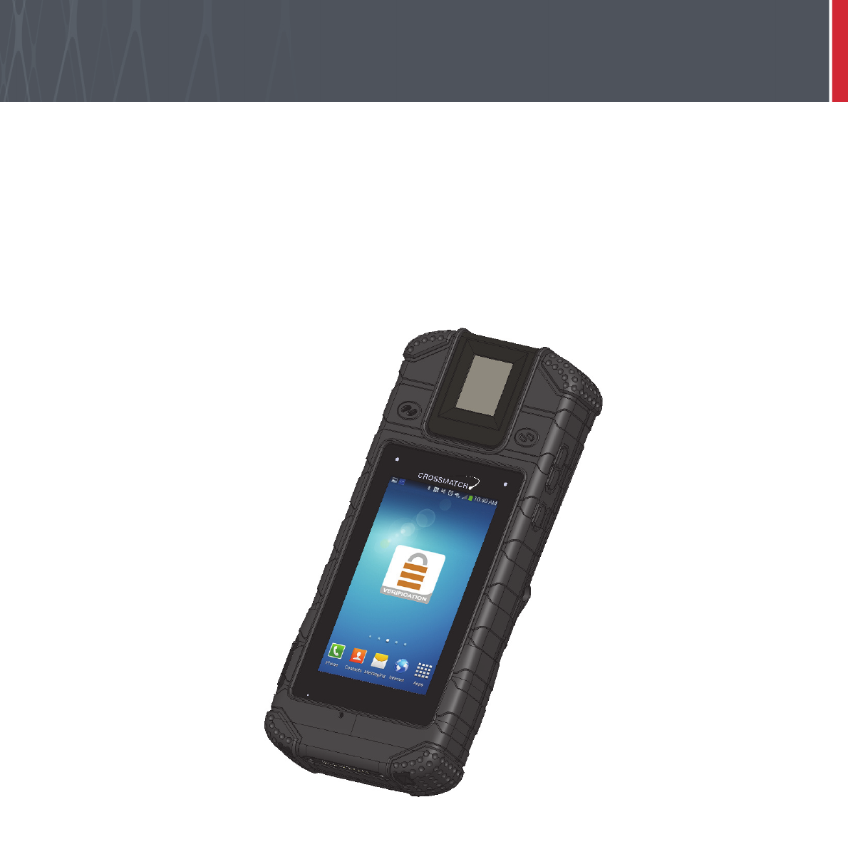
The Verifier® Sentry is a portable identification and verification device that provides many methods to capture
personal and biometric information. Strong design, small size and light weight makes the device easy to use in the
field. The device can scan CAC/PIV, Contact and Contactless smart cards. The Verifier Sentry can read the Machine
Readable Zone (MRZ) on an ePassport and read the chip embedded in the passport.
6Verifier® Sentry Operator Manual 870391 V1.0
IntroductionDescription
The front of the
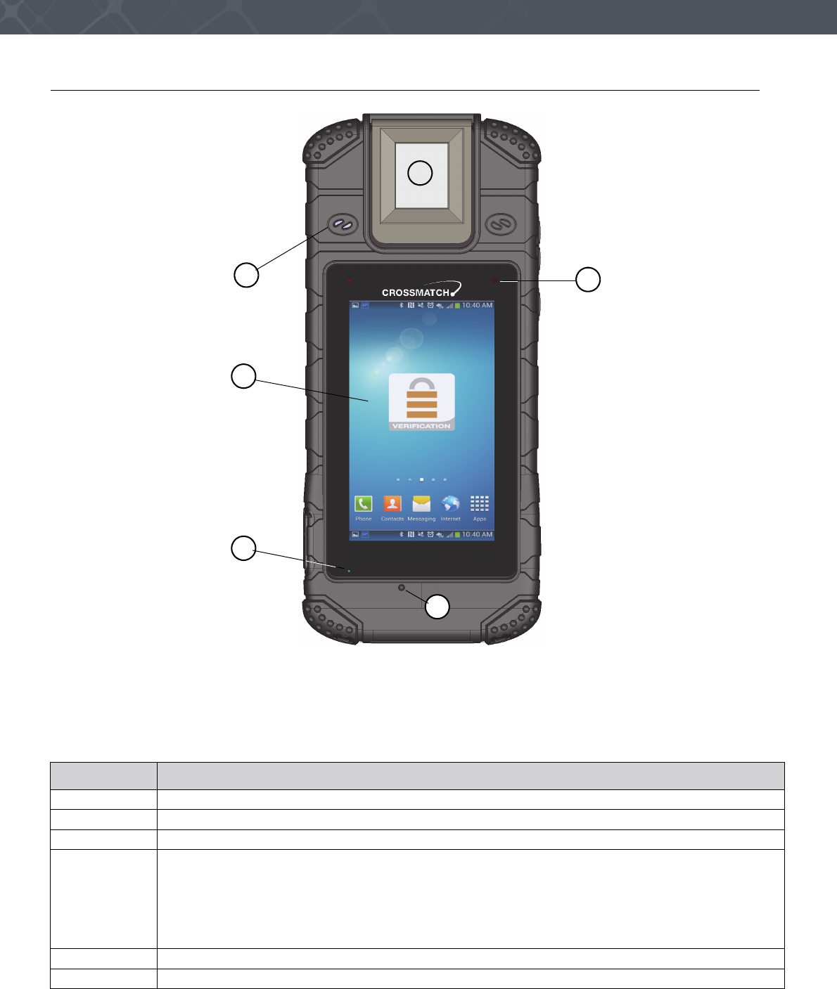
Figure 1
The front of the Sentry
The front of the Sentry contains the features that allow the operator to monitor the state of the device. The following
table describes the features.
Table 5
The front of the Sentry
Description
1The finger is pressed on the platen surface to capture the fingerprint.
2The speaker.
3The Capacitive Touch Screen is sensitive to contact by a finger or a capacitive stylus.
4When the battery accepts a charge, the Charge indicator illuminates.
• A Red light indicates 500 mA of electricity is supplied to the Sentry. This current the amount required to
operate the Sentry, but less than the amount required to charge the Sentry.
• An Amber light indicates 1500 mA of electricity is supplied to the Sentry.
• A Green light indicates the Sentry is supplied the correct amount of electricity by the Docking Station.
This arrangement allows the device to operate and accept the fastest rate of charge.
5The microphone.
6The Status indicator. The Android hardware API controls this LED.
1
5
2
3
4
6
7
Description
The left side of the Sentry
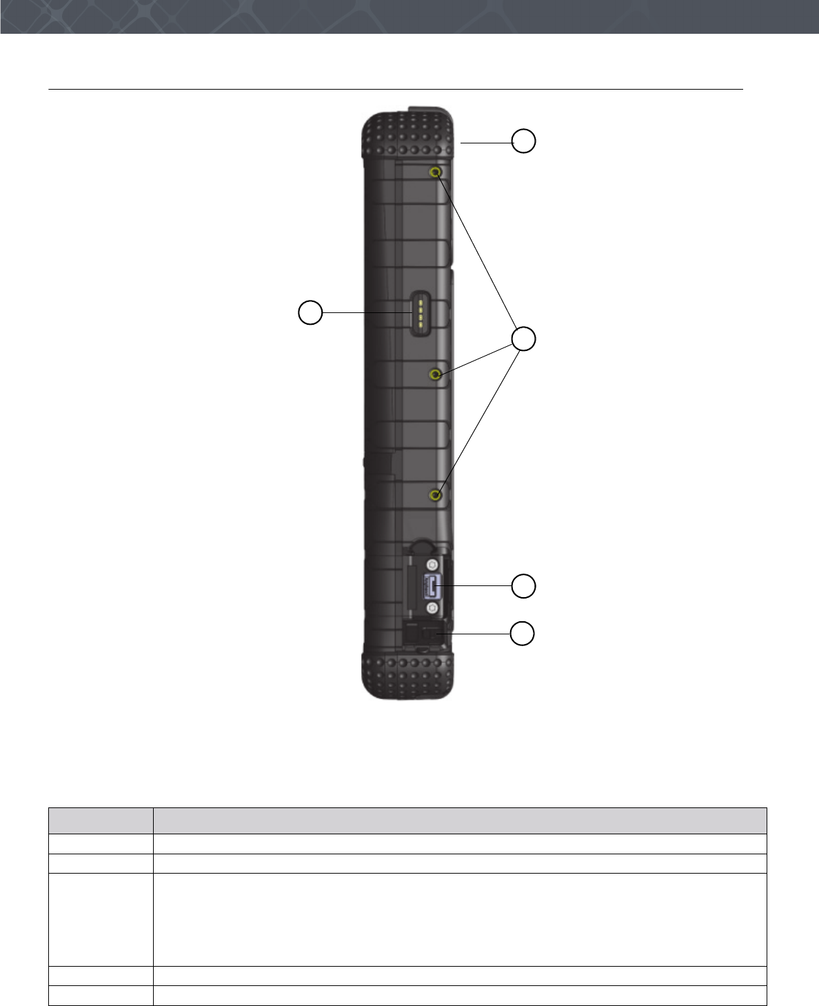
Figure 2
The left side of the Sentry
The following table describes the left side of the Sentry.
Table 6
The left side of the Sentry
Description
1The top-end of the Verifier Sentry.
2The mounting points for accessories.
3During normal operation, this port allows the Sentry to be a memory or camera device to a host
computer.
When the On The Go (OTG) adapter is used, the USB connector allows the Sentry to be a host
computer for an external USB device.
The connector can be a charge point.
When connected to a laptop, the connector is a device endpoint.
4The attached cover for the USB connector is shown open.
5This is the data connection for an accessory.
2
5
3
4
1
8Verifier® Sentry Operator Manual 870391 V1.0
IntroductionDescription
The right side of the Sentry
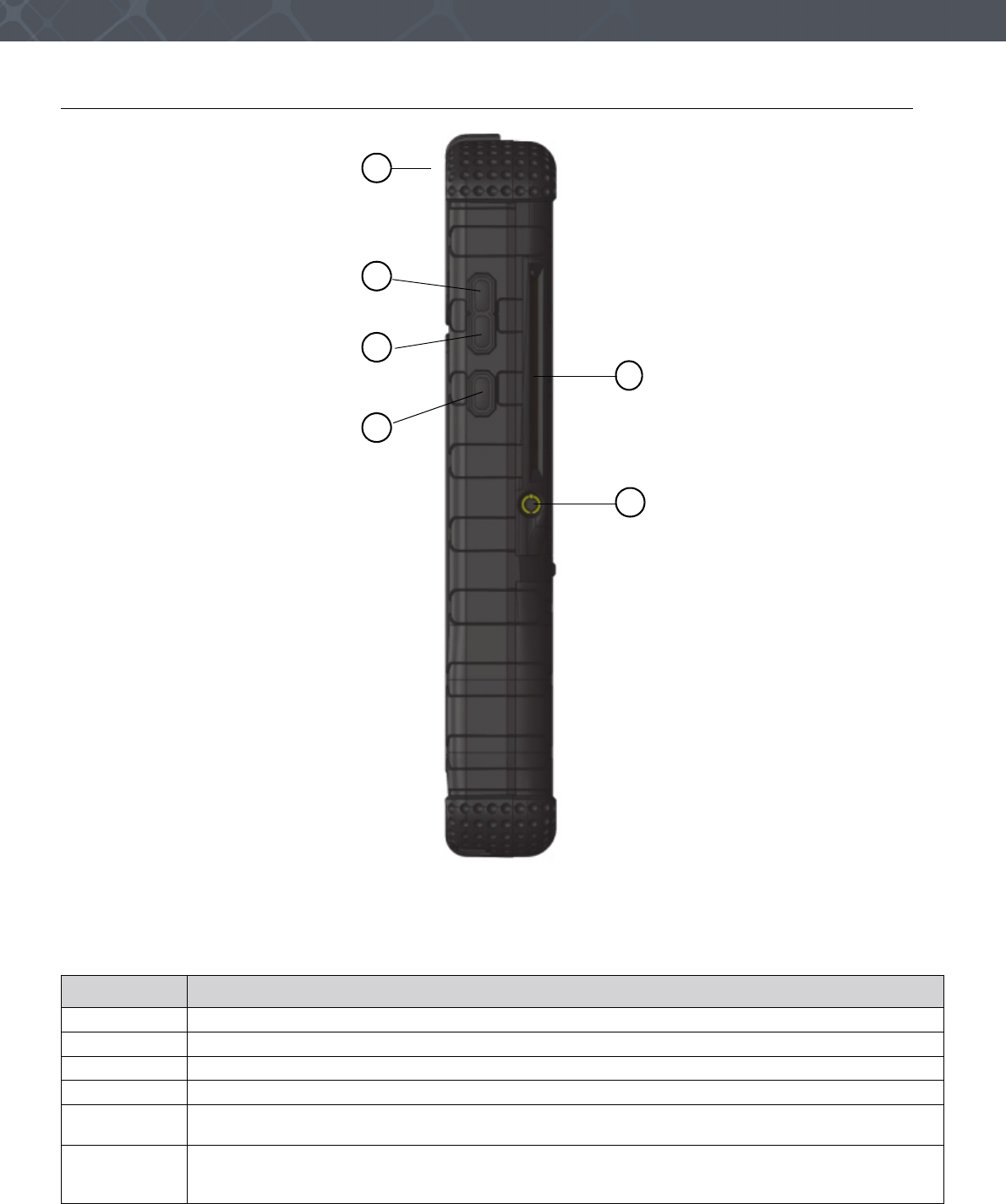
Figure 3
The right side of the Sentry
The following table describes the features on the right side of the Sentry.
Table 7
The right side of the Sentry
Description
1The top-end of the Verifier Sentry.
2The button to increase the output from the speaker or from the earphones.
3The button to decrease the output from the speaker or from the earphones.
4The Start button.
5The connection point for earphones and a microphone. The jack is one eighth of an inch in
diameter.
6The slot for a contact card. An application is required to display the data on the screen. When the
operator inserts the card, the gold contacts on the top surface of card must be visible. See “Scan a
Contact Card” on page 13.
4
3
5
6
2
1
9
Description
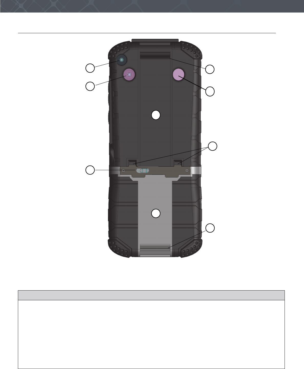
The back of the Sentry
Figure 4
The back of the Verifier Sentry
The following table describes the features on the back of the Sentry.
Table 8
The back of the Sentry
Description
1The camera and camera lens.
2The light source for the bar code scanner.
3The release latch for the battery cover.
4The cover for the battery compartment.
5Contactless card Reader area. The card can be outside the hand strap. See “Scan a
Contactless Card” on page 14.
6The attachment bars for the hand strap.
7Alignment slots for the docking station.
8The photo light source provides illumination for photos captured with the camera. The light is
disabled until the camera is enabled.
1
3
6
2
4
7
8
5
6
10 Verifier® Sentry Operator Manual 870391 V1.0
IntroductionDescription
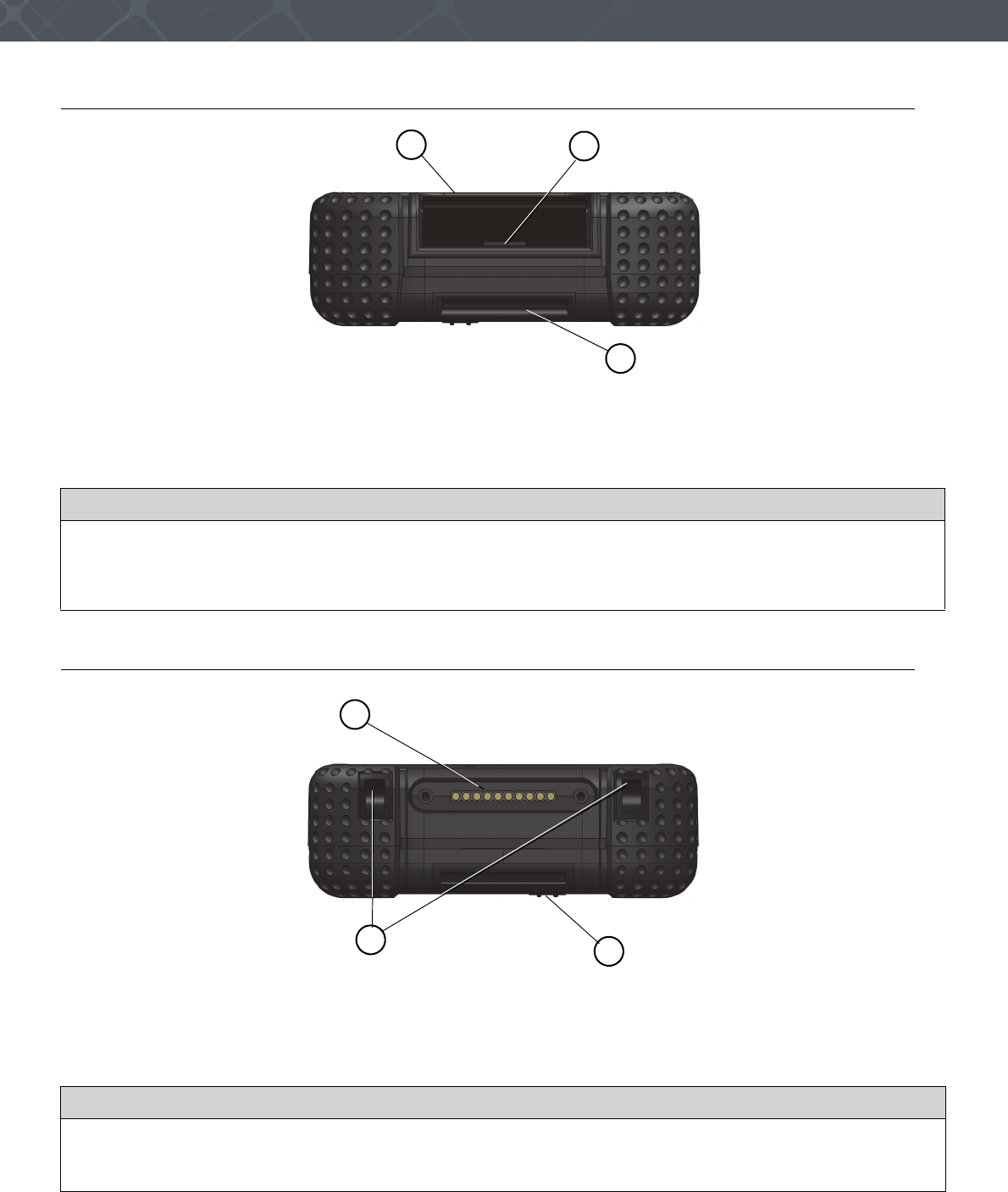
The top of the Sentry
Figure 5
The top of the Verifier Sentry
The following table explains the features on the top of the Verifier Sentry.
The bottom of the Sentry
Figure 6
The bottom of the Verifier Sentry
The following table describes the features of the bottom of the device.
Table 9
The top of the Verifier Sentry
Description
1The bezel around the platen.
2The slot allows a tool provided by Crossmatch to release the sensor from the Verifier Sentry. See “Replace
the fingerprint sensor” on page 24.
3The top attachment bar for the hand strap. The hand strap is not shown.
Table 10
The bottom of the Verifier Sentry
Description
1The connection point for the optional docking station.
2Two slots that fit over two tabs on the optional docking station to correctly align the Verifier Sentry.
3The bottom attachment bar for the hand strap.
2
1
3
1
3
2
11
Use the Sentry
THIS CHAPTER DESCRIBES HOW TO START AND STOP THE SENTRY. THE CHAPTER ALSO DESCRIBES THE TASKS THE
OPERATOR CAN PERFORM WITH THE SENTRY.
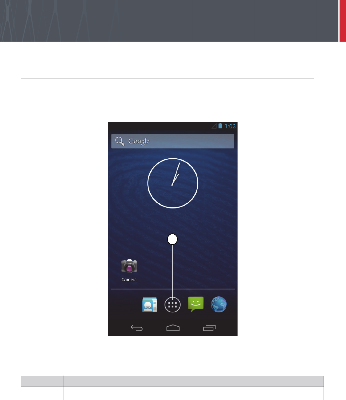
Start the Sentry
Follow the procedure to turn on the Sentry.
1 Press and hold the Start button. The Status indicator illuminates.
2 Release the Start button. The start sequence begins. The Sentry desktop appears. The Sentry is started.
The illustration shows the Sentry desktop. The desktop is a normal Android desktop. A tutorial is available on the
Internet for the Android JB operating system.
Table 11
Items on the Sentry desktop
Description
1The Apps icon. Touch this icon to see one or more screens that contain the icons for applications installed on
the Sentry.
1
1
12 Verifier® Sentry Operator Manual 870391 V1.0
IntroductionUse the Sentry
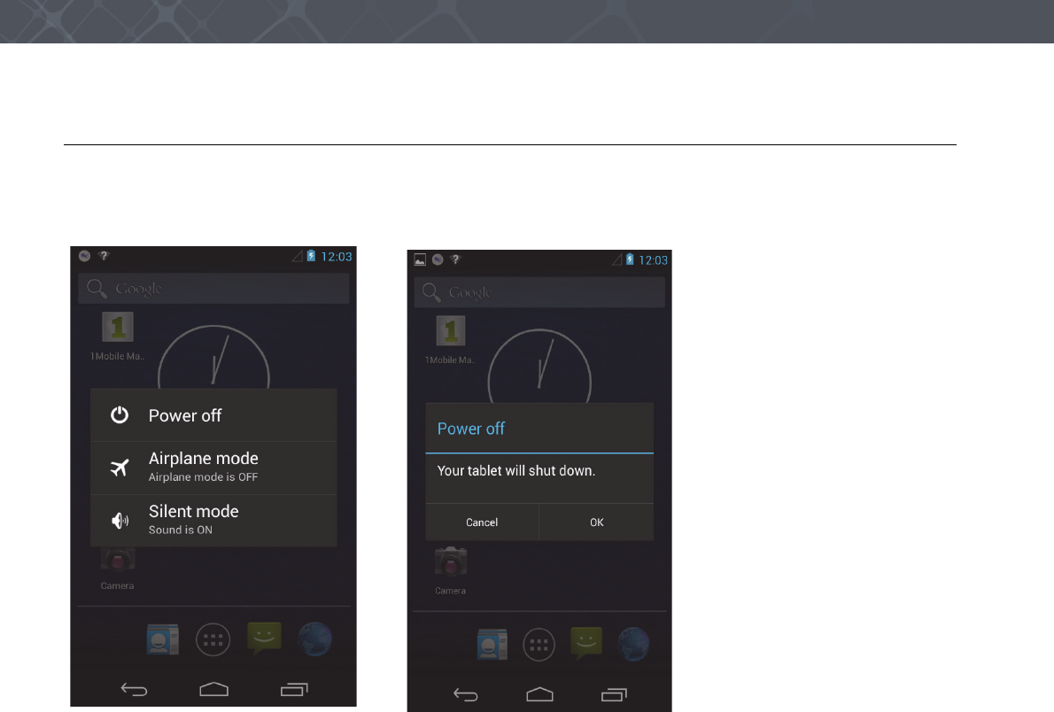
Stop the Sentry
Use the following steps to stop the Sentry.
1 Press and hold the Start button until the Mode menu appears.
2 Select Power off. The Power off menu appears.
3 Select OK to turn off the Sentry or select Cancel to return to the desktop.
The following sections describe the procedures that the operator can do with the Sentry. The illustrations in the
following procedures show a Crossmatch demonstration application. The actions for the procedures are the normal for
similar applications.
1 Start the application.
2 Sign into the application
3 The Home window appears with the Main menu for the application displayed. The main menu for other
applications can contain different selections.
13
Use the Sentry
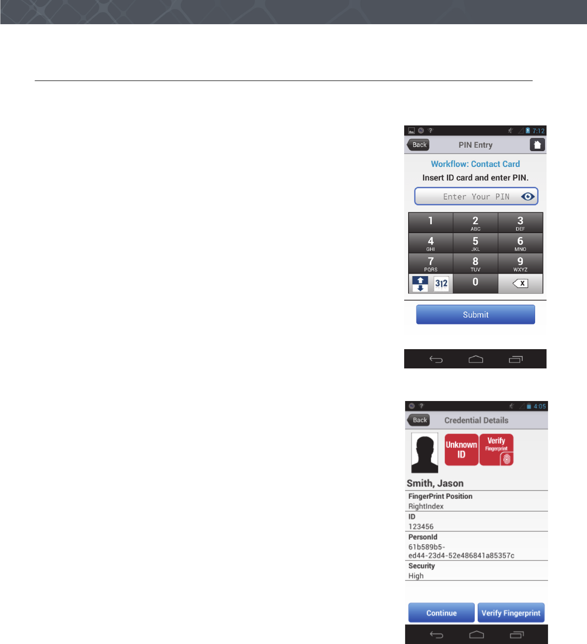
Scan a Contact Card
The following procedure shows how to scan data from a Contact card and verify the data with the Sentry. The
application in the illustration is a Crossmatch demonstration application. Your application can appear different.
1 Start the application.
2 Sign into the application The Home window appears with the Main menu for
the application displayed. The application in the illustration is a Crossmatch
demonstration application. Your application can be different.
3 Touch to select Contact Card. The instruction to insert the card and enter a PIN
appears.
4 Enter the PIN
5 Insert the card, with the picture visible, into the slot in the right-side of the
Sentry. See “The right side of the Sentry” on page 8.
6 Enter the PIN.
7 Touch the Submit button.
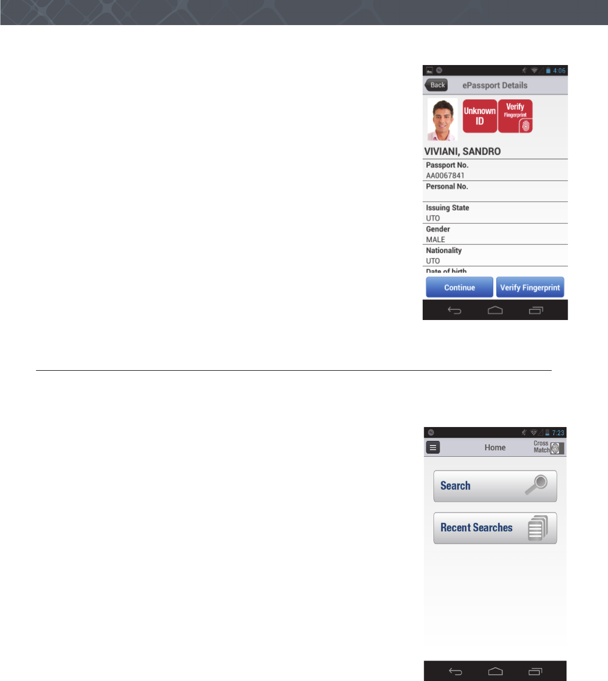
8 The Sentry scans the card and the application displays the data from the card on
the screen. The workflow in the example application requires the operator to
verify the fingerprint.
14 Verifier® Sentry Operator Manual 870391 V1.0
IntroductionUse the Sentry
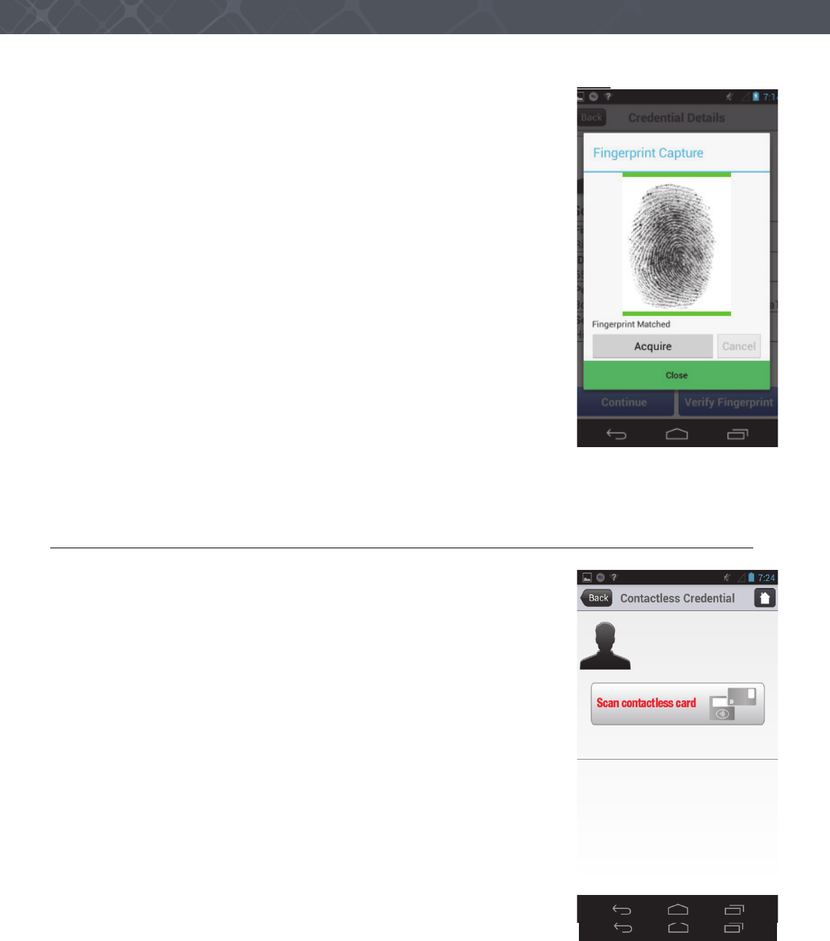
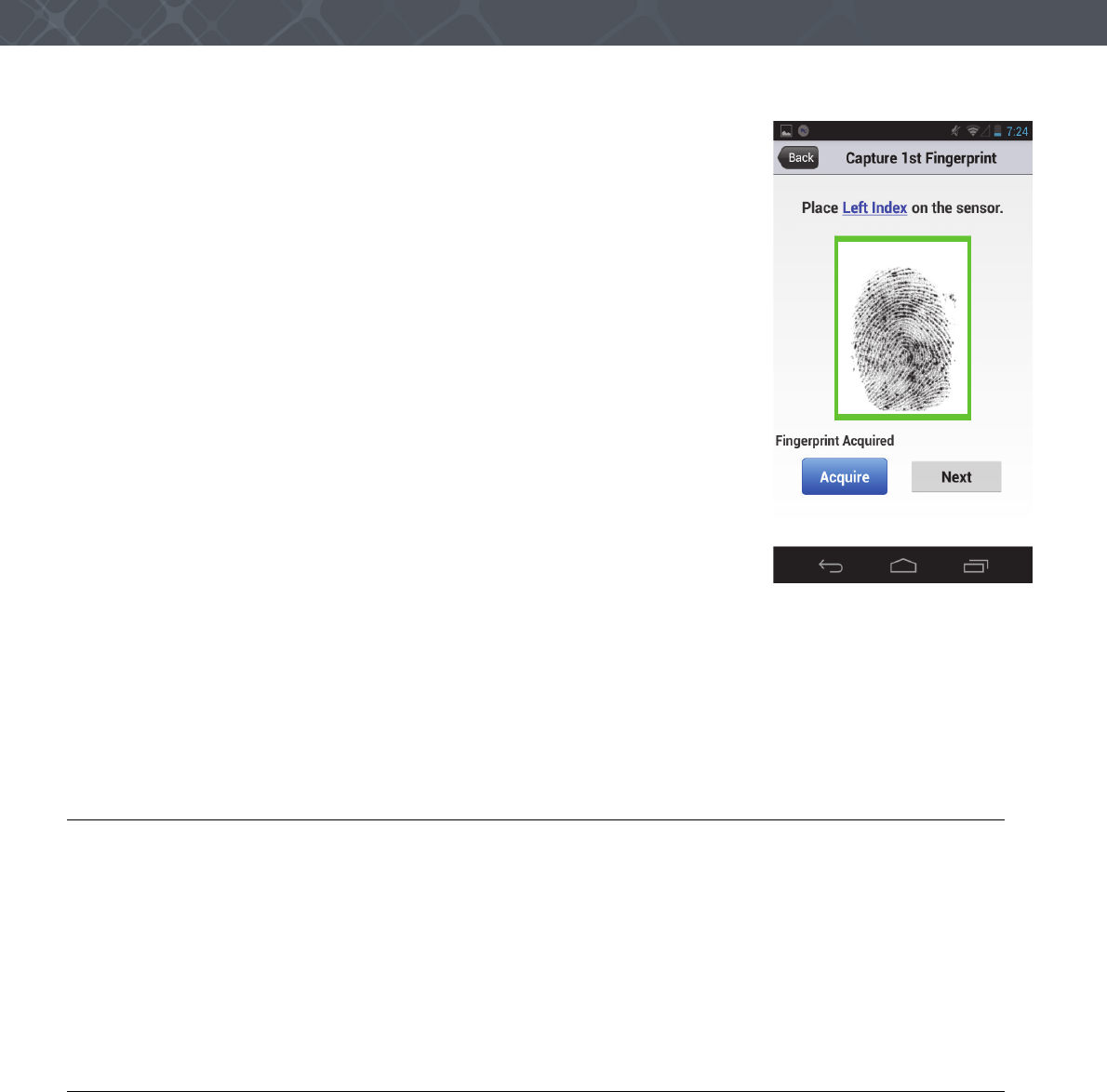
9 Touch the Verify Fingerprint button. The Fingerprint Capture window appears
10 Tell the person to press the correct finger on the platen of the Sentry. The
fingerprint appears in the window. The Sentry captures the fingerprint. The
application compares the fingerprint to the fingerprint stored on the card.
If the fingerprint matches, a green line appears above and below the fingerprint
and a message appears in the window.
If the fingerprint does not match, a red line above and below the fingerprint and
a message appears in the window.
11 Take the action required by the procedures for the organization.
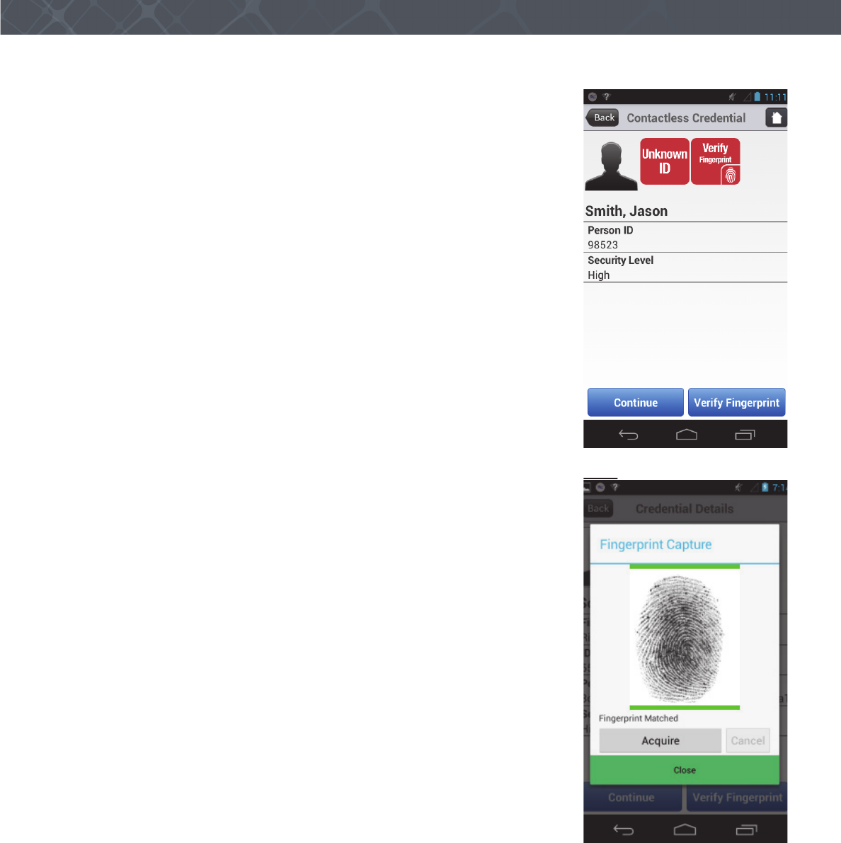
Scan a Contactless Card
The following procedure shows how to scan the data from a Contactless card and
verify the data with the Sentry. The application in the illustration is a Crossmatch
demonstration application. Your application can appear different.
1 Touch to select Contactless Card. The instruction to scan the card appears.
2 Put the card near the Contactless Card Reader area on the back of the Sentry. See
“The back of the Sentry” on page 9.
15
Use the Sentry
3 The Sentry scans the card and the application displays the data from the card on
the screen. If the scanner does not read the card, a message appears. The
workflow requires the operator to verify the fingerprint.
4 Touch the Verify Fingerprint button. The Fingerprint Capture window appears
5 Tell the person to press the correct finger on the platen of the Sentry. The
fingerprint appears in the window. The Sentry captures the fingerprint and the
application compares the fingerprint to the fingerprint stored on the card.
If the fingerprint matches, a green line appears above and below the fingerprint
and a message appears in the window.
If the fingerprint does not match, a red line above and below the fingerprint and
a message appears in the window.
6 Take the action required by the procedures for the organization.
16 Verifier® Sentry Operator Manual 870391 V1.0
IntroductionUse the Sentry
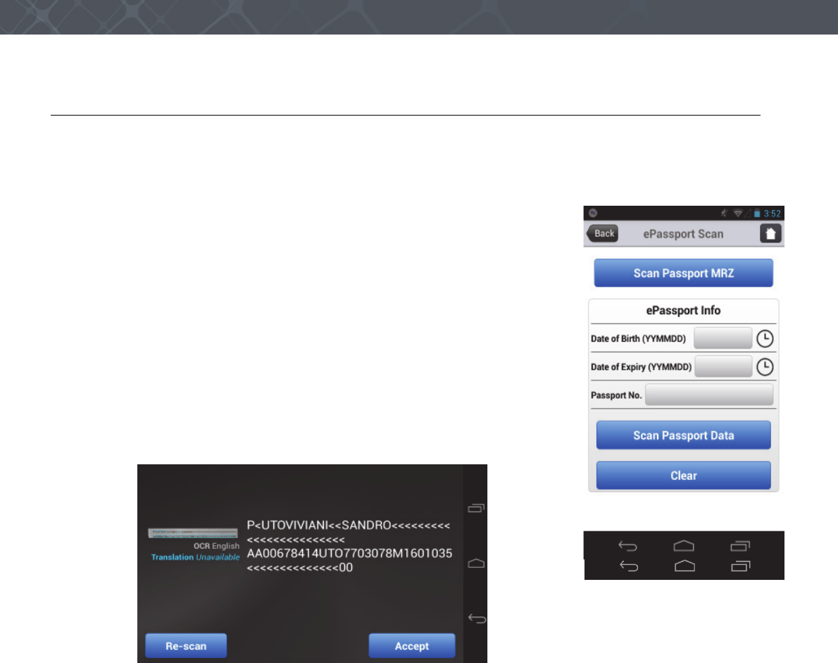
Read an ePassport
The following procedure shows how to scan the data from an ePassport with the Sentry.
Note
Some ePassports can contain levels of data encryption that the application cannot read.
1 Touch ePassport from the main menu. The ePassport Scan window appears. The
application in the illustration is a Crossmatch demonstration application. Your
application can appear different.
2 Touch Scan Passport MRZ. The Sentry camera turns on and displays a white
box.
3 Adjust the image of the MRZ area to appear inside the white box. The Sentry
scans the MRZ and displays the information in a screen
.
4 Touch Accept to keep the information, or touch Re-scan to scan the MRZ area again.
5 The Date of Birth, the Expiration Date and the Passport Number appear in the ePassport Scan screen.
Note
The operator can enter the required information in the ePassport information boxes. When the operator touches an
information box, the keyboard appears for data entry.
17
Use the Sentry
6 Put the page of the passport that contains the chip near the Contactless Card
Reader on the back of the Sentry. See “The back of the Sentry” on page 9. The
Sentry reads the chip and the application displays the data from the chip on the
screen.
Note
When the application does not read the encrypted data on the chip, a message appears
on the screen.
7 To complete the ePassport process, the operator takes the actions described in the
procedures for the organization.
Capture and verify the biometrics
An application is required to capture and save the biometrics for comparison to database records. The following steps
describe how to capture a fingerprint with a Crossmatch demonstration program. Your application can appear
different. The required steps are the same.
1 Start the application to capture the biometrics.
2 Sign into the application. The Home window appears.
3 Select Search to begin the fingerprint capture process.
18 Verifier® Sentry Operator Manual 870391 V1.0
IntroductionUse the Sentry
4 Follow the instructions on the screen to capture the fingerprints.
5 Follow the procedure to capture a face photo of the person.
6 The demonstration application puts a box on the screen.
7 Put the face of the person into the box. The application captures the photo.
8 Touch the Use button. The application compares the biometrics to a database and reports the results of the
comparison.
9 To complete the process, the operator takes the actions described in the procedures for the organization.
Capture a photograph
An application is required to capture a photograph and save the photograph in a record.
1 Start the Sentry.
2 Start the application to save the photograph.
3 Sign into the application.
4 Select the camera from the desktop.
5 Take the photograph.
6 Follow the instructions to save the photograph in the record.
Read a barcode
An application is required to read a barcode and save the data in a record. The application shown here is a Crossmatch
demonstration application.
1 Start the Sentry.
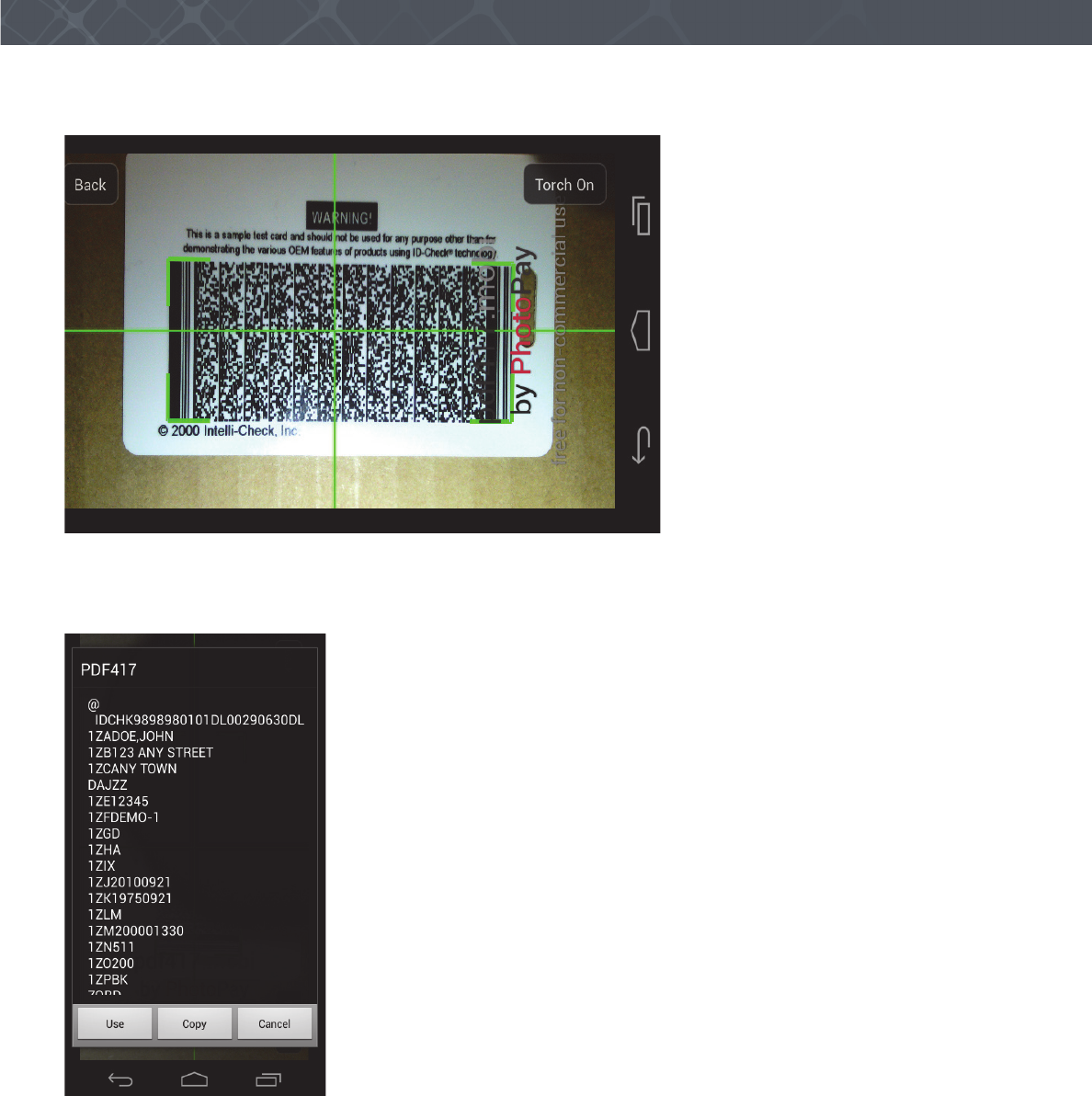
2 Start the application to scan the barcode. The camera starts and displays red cross hairs over the image.
3 If more light is required, touch the button that turns on the light.
19
Use the Sentry
4 Adjust the Sentry to center the cross hairs in the barcode.
The cross hairs turn green and green brackets appear to frame the barcode image. The application captures the data in
the barcode. The barcode information appears on the Sentry screen.
5 Follow the work flow instructions to save the barcode information.

20 Verifier® Sentry Operator Manual 870391 V1.0
IntroductionUse the Sentry
21
Maintenance
THIS DOCUMENT DESCRIBES THE MAINTENANCE THAT THE OPERATOR CAN PERFORM ON THE SENTRY.
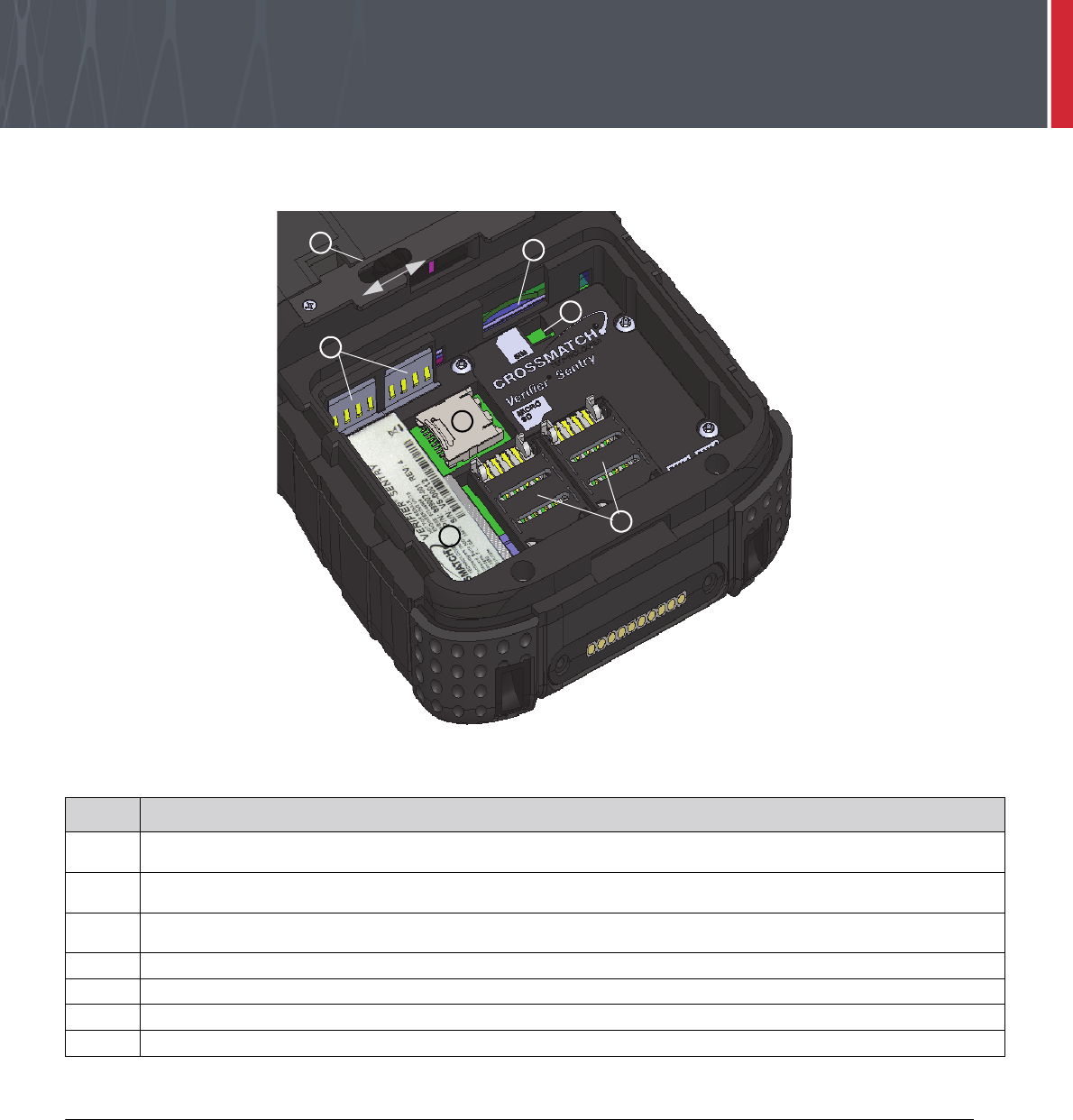
Figure 7
The Sentry battery compartment (battery removed)
Remove the battery
Use the following procedure to remove the battery.
1Press and hold the Start switch to turn off the Sentry.
2 Hold the Sentry with the back of the device visible.
3 Loosen the hand strap.
4 Slide and hold the latch for the cover in the open position.
5 Apply enough pressure to slide the cover away from the latch until it stops.
6 Release the latch and lift the cover from the Sentry.
7 Lift the bottom of the battery and remove the battery from the battery compartment.
Table 12
Items in the Sentry battery compartment
1The cover latch for the battery compartment. The latch slides to release the cover. The latch automatically returns to
the closed position.
2The socket for the SIM card accepts a normal size SIM card (recommended). An adapter tray is required for smaller
SIM cards.
3The latch that indicates that the battery is installed. The battery compresses the latch and the installation is
recorded in the log. When the battery is removed, the latch is released and the removal of the battery is recorded.
4The socket for a SAM card. There are two sockets.
5The product label for the Sentry.
6The Micro SD card socket.
7The battery connection points for the Sentry.
2
3
1
7
6
4
5
22 Verifier® Sentry Operator Manual 870391 V1.0
IntroductionMaintenance
Install the battery
1Remove the old battery, if necessary. See “Remove the battery” on page 21.
2 Hold the battery with the label visible.
3 Put the connection points on the battery against the connection points (7) in the battery compartment.
4 Press to install the battery.
5 Put the cover in position over the battery compartment.
Note
If the cover does not fit correctly over the battery compartment, check the position of the seal assembly inside the cover.
The assembly must extend under the hook for the cover latch. If necessary, slide the assembly toward the hook. When in
the correct position, the assembly stops.
6 Apply enough pressure to slide the cover toward the latch. When the cover closes, you hear the cover latch reset.
7 Tighten the hand strap.
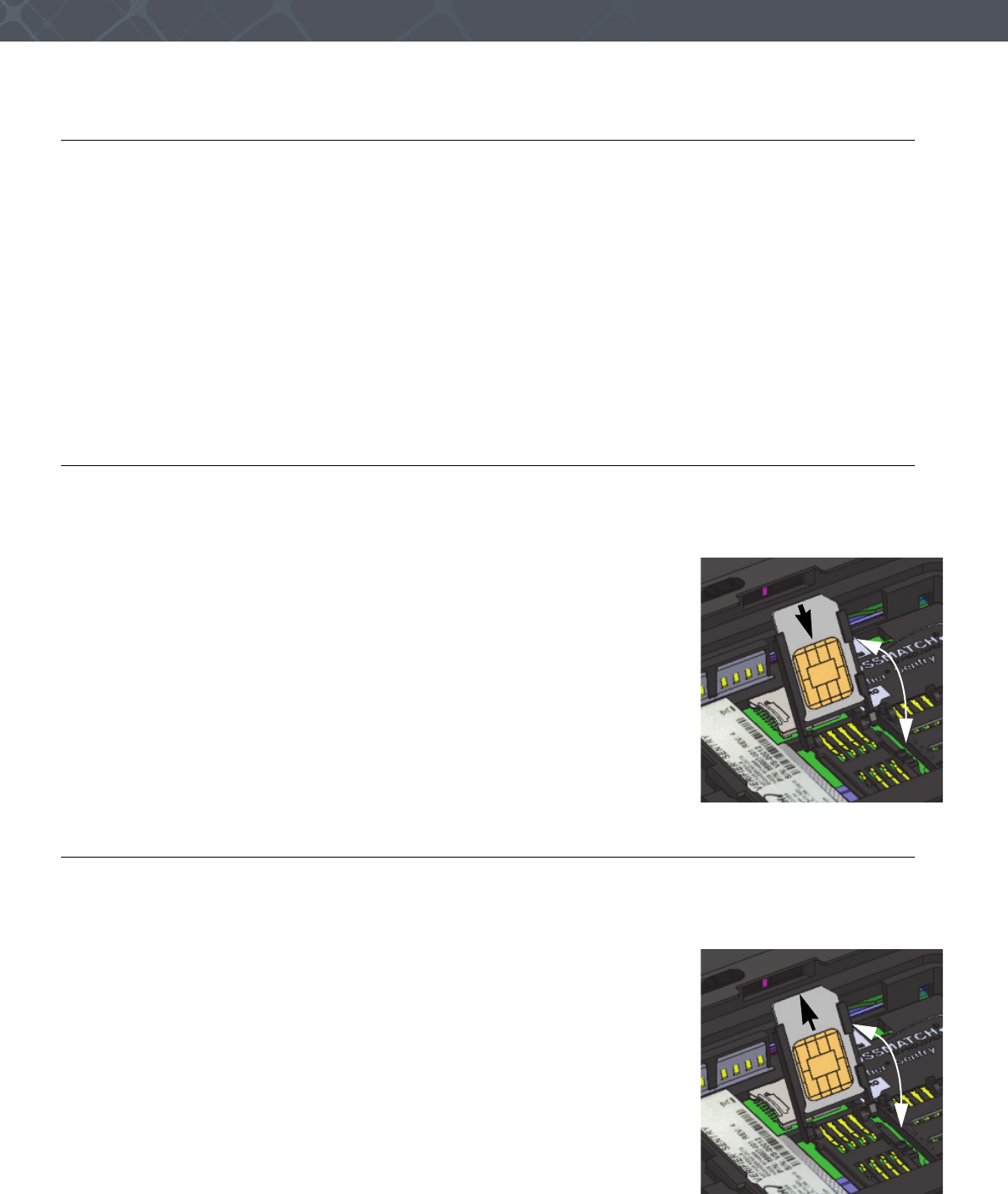
Insert a SAM card
Use the following procedure to insert a SAM card. There are two SAM card connectors in the battery compartment,
next to the Sentry label.
1Remove the battery. See “Remove the battery” on page 21.
2 Select an empty SAM connector.
3 Use a fingernail to unlock and move the SAM cover toward the center of the
Sentry.
4 Open the SAM cover until the cover stops.
5 Insert the SAM card into the cover. The card inserts with the chamfer on the card
as shown in the illustration.
6 Close and lock the SAM cover.
7 Insert the battery. See “Install the battery” on page 22.
Remove a SAM card
Use the following procedure to remove a SAM card. There are two SAM card connectors in the battery compartment,
next to the Sentry label.
1Remove the battery. See “Remove the battery” on page 21.
2 Select SAM card to remove.
3 Use a fingernail to unlock and slide the SAM cover toward the center of the
Sentry.
4 Open the SAM cover until the cover stops.
5 Slide the SAM card out of the cover.
6 Close and lock the SAM cover.
7 Insert the battery. See “Install the battery” on page 22.
23
Maintenance
Insert the SIM card
Use the following procedure to insert a SIM card into the Sentry. The SIM card connector is in the side of the battery
compartment next to the battery contacts.
1Remove the battery. See “Remove the battery” on page 21.
2 Insert the SIM card into the SIM slot and press until the card stays in the slot.
3 Insert the battery. “Install the battery” on page 22.
Remove the SIM card
Use the following procedure to remove a SIM card from the Sentry. The SIM card connector is in the side of the
battery compartment next to the battery contacts.
1Remove the battery. See “Remove the battery” on page 21.
2 Press the SIM card into the SIM slot until the card releases from the slot.
3 Remove the SIM card.
4 Insert the battery. See “Install the battery” on page 22.
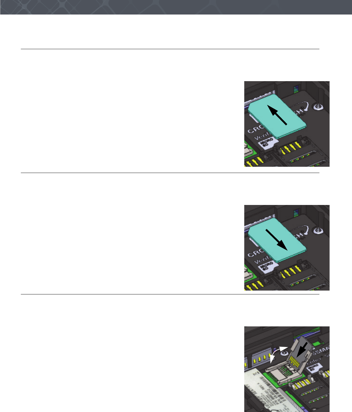
Insert the Micro SD card
Use the following procedure to insert the Micro SD card into the Sentry. The Micro SD card connector is in the floor of
the battery compartment, next to the battery contacts.
1Remove the battery. See “Remove the battery” on page 21.
2 Use a fingertip to slide the Micro SD cover toward the Sentry label and unlock
the cover.
3 Open the cover.
4 Insert the Micro SD card into the cover.
5 Close the cover on the Micro SD card connector.
6 Insert the battery. See “Install the battery” on page 22.

24 Verifier® Sentry Operator Manual 870391 V1.0
IntroductionMaintenance
Remove the Micro SD card
Use the following procedure to remove the Micro SD card from the Sentry. The Micro SD card connector is in the floor
of the battery compartment, next to the battery contacts.
1Remove the battery. See “Remove the battery” on page 21.
2 Use a fingertip to slide the Micro SD cover toward the Sentry label and unlock
the cover.
3 Open the cover.
4 Remove the Micro SD card.
5 Close and lock the cover on the Micro SD card connector.
6 Insert the battery. See “Install the battery” on page 22.
Find the Product Label
Use the following procedure to find the product label for the Sentry.
1Remove the battery. See “Remove the battery” on page 21.
2 The product label is visible in the battery compartment near the two SAM card connectors.
3 Insert the battery. See “Install the battery” on page 22.
Replace the fingerprint sensor
If the fingerprint sensor must be changed, Crossmatch provides a Sensor Replacement kit. The part number of the kit is
8880125-001. The kit includes a sensor, a special tool and complete instructions to replace the sensor.

25
Customer Care
THIS CHAPTER DESCRIBES THE TECHNICAL ASSISTANCE AVAILABLE FOR THE SENTRY AND PROVIDES CONTACT INFORMATION.
Technical Support
Technical support from the Customer Care department is available for the Sentry.
E-mail
Cross Match Customer Care provides free technical support on-line during the warranty period, in the order that the
requests are received.
If the warranty has expired, use the telephone or facsimile to contact the Customer Care department.
Telephone and facsimile
The Customer Care is available at the following telephone numbers:
Technical support is available for the Sentry during the warranty period at zero charge (see “Warranty” for Warranty
Terms). After the warranty has expired, technical support is available at a given cost per hour. Contact the Customer
Care department.
The Customer Care for the software products and the services purchased from Cross Match Technologies is not
included in the warranty. The Customer Care for other products is available at a given cost to the customer.
When you contact the Customer Care department, make sure that you can provide the following information:
• Company name
• Contact person
• The Sentry serial number
• The error messages that appear on the screen
Global
CustomerCare@crossmatch.comGlobal
Global
Monday- Friday 8 am to 6 pm EST
Customer Care
Tel: 1.866.276.7761 (Toll Free)
Tel: 1.561.622.9210 (International)
Fax: 1.561.622.8769

26 Verifier® Sentry Operator Manual 870391 V1.0
IntroductionCustomer Care
Return and repair of the Sentry
You must receive an RMA number to return the Sentry for repair or replacement. Contact the Customer Care
department to request and receive an RMA number. Put the RMA number on the outside of the box and on the label.
The product is sent to the correct department for service or replacement, then returned to the customer. Any product
sent to Cross Match Technologies without an RMA number is returned.
Delivery costs
The product is in the warranty period
• The customer accepts all charges to send the product to Cross Match for service.
• Cross Match accepts all charges to return the product to the customer.
The product is not in the warranty period
• The customer accepts all charges.
Note
You must return a product in the original boxes. If the original boxes are not available,
contact the Customer Care department for instructions.
Contact information
Corporate Headquarters
Cross Match Technologies, Inc.
3950 RCA Boulevard, Suite 5001
Palm Beach Gardens, FL 33410
USA
T: +1 (561) 622-1650
F: +1 (561) 622-9938
T: (866) 725-3926 (Toll Free)
General Mailbox: info@crossmatch.com
Sales Department: sales@crossmatch.com
Customer Care: CustomerCare@crossmatch.com
Corporate Web Page: www.crossmatch.com
North and South America
Cross Match Technologies, Inc.
3960 RCA Boulevard, Suite 6001
Palm Beach Gardens, Florida
33410
USA
RMA: Rnnnn.nnnn

27
Warranty
THIS CHAPTER CONTAINS THE CROSSMATCH WARRANTY FOR THE SENTRY.
Warranty and Remedy
Cross Match Technologies, Inc. (Cross Match) warrants that the Cross Match Product (other than customized
software) you have purchased will be free from defects in material and workmanship in normal service and under
normal conditions for a period of one year from the date of shipment. Normal service and normal conditions are
defined in the Product documentation. This Limited Warranty is subject to the terms and conditions set forth below.
Repair or Replacement: Unless otherwise stated herein, the sole obligation of Cross Match and your exclusive remedy
and recourse under this Limited Warranty is for Cross Match, at its sole election, to either (i) repair the suspected
defective Product and return the same to you or (ii) replace the suspected defective Product, all on the terms set forth
below. The repair or replacement will provide you with a Product which, in Cross Match's opinion, performs
consistently with its age and usage.
If you become aware that your Cross Match Product is defective in material or workmanship in normal service and
under normal conditions during its one year Limited Warranty period, then you must promptly contact Cross Match's
Customer Care Center, describe the suspected defect in detail and request a Return Merchandise Authorization (RMA)
number prior to sending the affected Product for repair or requesting a replacement product. Please see your product
manual for more information on RMA's. You will pay the freight to send the Product to Cross Match's designated
Service Center, and Cross Match will pay the freight to return the repaired Product to you. Each repaired or
replacement Product is warranted (as set forth herein) for the remaining portion of the original one year Limited
Warranty.
THE FOREGOING CONSTITUTES YOUR SOLE AND EXCLUSIVE REMEDY AND CROSS MATCH'S SOLE
AND EXCLUSIVE LIABILITY IN CONNECTION WITH YOUR CROSS MATCH PRODUCT, AND IS IN LIEU
OF ANY AND ALL OTHER REMEDIES WHICH MAY BE AVAILABLE TO YOU.
Limitations
This limited warranty does not cover visits to repair the Cross Match product at your premises, or the commissioning
of the Product on site. This Limited Warranty is not a warranty, guarantee or promise that your Cross Match Product
will conform to its specification or will not fail. Some defects and failures are not covered.
Cross Match shall incur no liability under this Limited Warranty and this Limited Warranty is voidable by Cross Match
if in Cross Match's sole reasonable opinion: (a) the Product is used other than under normal use and under proper
environmental and/or electrical conditions, as specified in the Product manual; (b) the Product is not maintained as
specified in the Product manual; (c) the Product is subject to abuse, misuse, neglect, accident, flooding, storm,
lightning, power surges, dirty power, third-party errors or omissions, or acts of God; (d) the Product is modified or
altered (unless expressly authorized in writing by Cross Match); (e) the Product is installed or used in combination or
in assembly with products not supplied or authorized by Cross Match; (f) there is a failure to follow specific
restrictions or operating instructions; or (g) payment for the Product has not been timely made.
This Limited Warranty includes software “updates” (a revision or minor change to a Product intended to correct
defects and provided as a change in the then current release of the Product). Software updates may be made from time
to time in Cross Match's sole discretion. This Limited Warranty does not cover software “upgrades” (a revision to a
Product that adds new enhancements and functionality resulting in a new release of the Product) or any software
product or interface customized by Cross Match to meet Purchaser's specific requirements or Purchaser furnished
equipment or software. Software upgrades may be available for purchase from time to time at Cross Match's then
current published prices.
This Limited Warranty does not provide additional hardware or computing platform software or its installation when
required by Cross Match software supplied hereunder. If required, these may be obtained from Cross Match at the
published prices in effect at such time.
The Limited Warranty does not cover nondurable consumable items including, but not limited to, batteries, paper,
silicon pads, cleaning solution, towels, printer cartridges and cables. Replacement supplies of these items may be
ordered by contacting Cross Match Sales at 866-725-3926. This Limited Warranty does not cover third party
peripheral equipment (such as laptops and printers) that are not provided by Cross Match.

28 Verifier® Sentry Operator Manual 870391 V1.0
IntroductionWarranty
Cross Match's obligations hereunder are contingent upon your providing the Product serial number as proof-of-
purchase, and upon Cross Match's determination that the suspected malfunction is actually due to defects in material or
workmanship.
THIS LIMITED WARRANTY IS IN LIEU OF ALL OTHER WARRANTIES RELATED TO THE CROSS MATCH
PRODUCT, WHETHER EXPRESS, IMPLIED, OR STATUTORY, INCLUDING THE WARRANTIES OF
MERCHANTABILITY AND FITNESS FOR A PARTICULAR PURPOSE, ALL OF WHICH ARE HEREBY
EXPRESSLY DISCLAIMED BY CROSS MATCH. THIS LIMITED WARRANTY IS NOT TRANSFERABLE OR
ASSIGNABLE TO ANY THIRD PARTY AND SHALL BE FOR THE SOLE AND EXCLUSIVE BENEFIT OF
THE ORIGINAL PURCHASER OF THE CROSS MATCH PRODUCT COVERED HEREUNDER; ANY
ATTEMPTED TRANSFER OR ASSIGNMENT HEREOF SHALL BE VOID AB INITIO.
Cross Match reserves the right to improve/modify products at any time, at its sole discretion, as it deems necessary.
Out-of-Warranty Repairs
When warranty coverage for your Cross Match Product lapses, or for repairs or replacements not covered by Cross
Match's warranty, (i) you will pay for all repairs at Cross Match's then-prevailing hourly labor rate (with a one hour
minimum) plus parts and shipping, (ii) you will pay Cross Match's then-current price for all replacement Products plus
shipping, and (iii) you will pay Cross Match's then-prevailing hourly labor rate (with a one hour minimum after the first
15 minutes) for telephone support in 15 minute increments.
To obtain out-of-warranty service, you must obtain an RMA number and send the affected Product, at your expense, to
the designated Cross Match Service Center for inspection. You will be contacted with an estimated price and time of
repair or replacement after analysis. No repairs or replacements will be made until Cross Match receives a Purchase
Order or credit card number from you. You shall pay return freight charges, which will be added to the invoice, for the
return of the repaired Product or replacement Product.
In the event you decide not to have a unit repaired or replaced after receiving a repair estimate, there will be a one hour
labor charge at the prevailing hourly rate for evaluation plus return freight charges.
At your request, Cross Match will, for a premium, ship a refurbished unit to you in exchange for the failed unit. Cross
Match will contact you with a price for the exchange after receipt of the failed unit. The shipment will be made when
Cross Match receives a Purchase Order or credit card number from you. You will pay return freight charges, which will
be added to the invoice, for the exchange unit. The original returned Product will become the property of Cross Match
and will not be returned to you. The refurbished unit will retain the remaining warranty term of the original returned
Product.

Index-1
Index
A
alignment slots for the docking station 9, 10
applications 2
attachment bars for the hand strap 9
Auto Capture™ 1
B
back of the Sentry 9
battery compartment cover 9
battery cover release latch 9
battery disposal 3
bezel cover release 10
biometric / credential capture 2
bluetooth 1
bottom attachment for the hand strap 10
bottom of the Sentry 10
button to decrease the volume 8
C
camera and camera lens 9
capture a photograph 17, 18
capture and verify the biometrics 17
change the battery 21
charge light 6
charge point 7
company
sales number 26
contact card slot 8
contact information 26
corporate headquarters 26
contactless card reader 9
corporate headquarters 26
corporate web page 26
Cross Match WEEE registration number 3
D
data connection for an accessory 7
delivery costs 26
desktop for the Sentry 11
device endpoint 7
docking station alignment slots 9
docking station connection 10
E
e-mail 25
e-mail, see contact information
F
FCC statement 2
flat fingerprints 1
flats 1
freight guidelines 26
not under warranty 26
under warranty 26
front of the Sentry 6
G
glossary 1
Auto Capture™ 1
bluetooth 1
flat fingerprint 1
GPS 1
USB 2.0 1
user 1
Wi-Fi 1
H
hand strap attachment 10
help 25
technical 25
how this book is arranged 1
how to use the Sentry 11, 21, 25, 27
I
Industry Canada statement 3
insert a micro sd card 23
insert a sam card 22
insert a simm card 23
insert the Micro SD card 23
insert the SIM card 23
install the battery 22
L
left side of the Sentry 7
licenses 3
the Cellular License information for Gemalto M2M
GmbH 3
Wi-Fi/Bluetooth License from LS Research 3
light source for the bar code reader 9
M
microphone 6
N
not under warranty 26
O
out-of-warranty repairs 28
P
photo light source 9
platen 1
platen bezel 10
platen surface 6
product in warranty period 26
product label for the Sentry 24
product not in warranty period 26
R
read a barcode 18
read a contact card 18
read an epassport 16
recycling information 3
remove a SAM card 22
remove the battery 21
remove the Micro SD card 24

Index-2 Verifier® Sentry Operator Manual 870391 V1.0
Index
remove the SIM card 23
return and repair of the Avenger 26
returns and repair 26
right side of the Sentry 8
right side of the sentry 8
rma number 26
S
scan a contact card 13
scan a contactless card 14
Sentry
attachment for the hand strap 10
back 9
battery compartment cover 9
bezel around the platen 10
bottom 10
bottom attachment for the hand strap 10
button to decrease the volume 8
button to increase the volume 8
camera and camera lens 9
capture a photograph 18
capture and verify the biometrics 17
charge light 6
charge point 7
connection point for the optional docking station 10
cover for the battery compartment 9
data connection for an accessory 7
desktop 11
docking station alignment slots 10
front 6
left side 7
light source for photos 9
light source for the bar code reader 9
microphone 6
platen surface 6
read a barcode 18
reader for a contactless card 9
release for the bezel cover 10
release latch for the battery cover 9
right side 8
scan a contact card 13
scan a contactless card 14
slot for a contact card 8
speaker 6
start 11
start button 8
tasks 25, 27
top 10
touch screen 6
USB connector 7
USB connector cover 7
speaker 6
specifications 2
standards 1
start button 8
start the Sentry 11
supplies 26
T
tasks with the Sentry 25, 27
technical help 25
technical support 25
e-mail
returns and repair 26
telephone and fax 25
telephone and facsimile 25
terms
platen 1
top of the Sentry 10
touch screen 6
U
under warranty 26
USB 2.0 1
USB connector 7
USB connector cover 7
user 1
V
volume buttons 8
W
warranty
limitations 27
out-of-warranty repairs 28
web page 26
WEEE directive 3
WEEE registration number 3
WiFi 1