Cross Point CP300MAXTRXA Electronic Article Surveillance(EAS) Pedestal User Manual title
Cross Point b.v. Electronic Article Surveillance(EAS) Pedestal title
user manual

Technical Manual AM Systems

Technical Manual AM Systems
Terms and abbreviations v4.4 Page 2 of 72
Table of contents
Technical Manual AM Systems .................................................................................................. 1
1 Terms and abbreviations ...................................................................................................... 5
2 Introduction ........................................................................................................................... 6
2.1 Available AM systems ................................................................................................... 6
2.2 Field Bus Network structure .......................................................................................... 6
2.3 Visitor counting .............................................................................................................. 6
2.4 Restrictions and limitations ............................................................................................ 8
2.4.1 AM systems versus RF systems ....................................................................... 8
2.4.2 Model restrictions .............................................................................................. 8
2.4.3 Software restrictions .......................................................................................... 8
2.4.4 Detection distances ........................................................................................... 8
3 General AM and EAS issues ................................................................................................ 9
3.1 Noise sources ................................................................................................................ 9
3.2 Installation guidelines .................................................................................................... 9
4 Equipment and tools ........................................................................................................... 11
4.1 General installation tools ............................................................................................. 11
4.2 Laptop computer .......................................................................................................... 11
4.3 Software ...................................................................................................................... 11
5 AM operating principle ....................................................................................................... 12
5.1 Synchronization principle ............................................................................................ 13
6 Connections......................................................................................................................... 15
6.1 “A” and “B” side of the antenna ................................................................................... 15
6.2 How to access the electronic boards........................................................................... 16
6.3 Field Bus connections ................................................................................................. 17
6.3.1 Bus connections with laptop ............................................................................ 17
6.4 Field Bus termination ................................................................................................... 18
6.4.1 TRX bus termination ........................................................................................ 18
6.4.2 RX bus termination .......................................................................................... 18
6.5 Power supply unit AM systems ................................................................................... 19
6.6 Power supply specifications ........................................................................................ 20
6.7 Switching to a different mains voltage ......................................................................... 20
6.8 Power supply restrictions ............................................................................................ 20
6.8.1 Power supply for a single system (mono) ....................................................... 21
6.8.2 Power supply for a dual system ...................................................................... 21
6.8.3 Power supply for a triple system ..................................................................... 22
6.8.4 Power supply for large system setup .............................................................. 23

Technical Manual AM Systems
Terms and abbreviations v4.4 Page 3 of 72
6.9 Antenna wiring ............................................................................................................. 24
6.10 The AM Transceiver (TRX) ......................................................................................... 25
6.10.1 AM Transceiver Printed Circuit Board ........................................................... 26
6.10.2 Transceiver - receiver cable connections ...................................................... 30
6.10.3 I/O connections.............................................................................................. 31
6.11 The AM Receiver (RX) ................................................................................................ 32
6.11.1 AM Receiver Printed Circuit Board................................................................ 32
6.12 The visitor counter ....................................................................................................... 34
6.13 Various connections .................................................................................................... 35
6.13.1 Single antenna system (no aisle) .................................................................. 35
6.13.2 Dual antenna system (single aisle) ............................................................... 36
6.13.3 Triple antenna system (double aisle) ............................................................ 37
6.13.4 Quad antenna system (triple aisle) ............................................................... 38
6.13.5 Large systems ............................................................................................... 38
7 Configuration ....................................................................................................................... 39
7.1 General connections.................................................................................................... 39
7.2 TRX configuration settings .......................................................................................... 39
7.3 TRX configuration – Device Explorer .......................................................................... 39
8 Cross Point Device Explorer .............................................................................................. 40
8.1 Starting the Device Explorer ........................................................................................ 40
8.2 Logon to Device Explorer ............................................................................................ 40
8.3 Store overview ............................................................................................................. 41
8.4 Dashboard ................................................................................................................... 41
8.5 Logon to the connected devices .................................................................................. 43
8.6 Creating entrances ...................................................................................................... 44
8.7 Configuring entrances ................................................................................................. 45
8.7.1 Entrances - Top part ........................................................................................ 45
8.7.2 Main menu ....................................................................................................... 46
8.7.3 3D antenna view .............................................................................................. 46
8.7.4 Entrances – selected entrance ........................................................................ 50
8.7.5 Entrances – selected antenna ......................................................................... 55
8.8 System ......................................................................................................................... 65
8.8.1 Notifications ..................................................................................................... 65
8.8.2 AM settings ...................................................................................................... 66
8.8.3 Alarm history .................................................................................................... 67
8.8.4 Devices ............................................................................................................ 68
8.9 Device Explorer Button Bar ......................................................................................... 70
8.10 Home view ................................................................................................................... 70

Technical Manual AM Systems
Terms and abbreviations v4.4 Page 4 of 72
8.11 Perspective view .......................................................................................................... 70
8.12 Counting view .............................................................................................................. 70
8.13 Entrance view .............................................................................................................. 71
8.14 Toggle view direction ................................................................................................... 71
9 Regulatory information ....................................................................................................... 72

Technical Manual AM Systems
Terms and abbreviations v4.4 Page 5 of 72
1 Terms and abbreviations
This chapter describes the terms and abbreviations used in this document.
Term
Abbreviation
Explanation
(Hard) Tag
Tag
Passive component, equipped with a lock
to allow attachment to garments, which
can be detected by the receiver.
(Paper) Label
Label
Passive component, usually equipped
with glue on one side to allow attaching
the label to any object, which can be
detected by the receiver.
Antenna
ANT
The mechanical structure (which usually
consists of a frame, wires and electronic
PCB) to allow proper detection of tags
and labels.
Also referred to as: pedestal, barrier.
Burst Frequency
Fb
The operating frequency of the TRX.
Device Explorer
Device Explorer
Cross Point Device Explorer
Software tool for adjustment of Cross
Point devices that are connected to the
Cross Point Field Bus structure (RS-485).
EAS
EAS
Electronic Article Surveillance
Foiled Twisted Pair
FTP
The FTP cable is surrounded by an outer
foil shield.
I/O
I/O
Digital Input/Output
Printed Circuit Board
PCB
The electronic board.
Radio Frequency
RF
Electronic signals generated by a
transmitter and detected by a receiver.
Receiver
RX
Electronic device capable of receiving
AM signals.
Transceiver
TRX
Electronic device capable of transmitting
and receiving AM signals, sharing the
same electronic circuitry and housing.
Also referred to as mono-antenna.
Unshielded Twisted Pair
UTP
Common network cable.

Technical Manual AM Systems
Introduction v4.4 Page 6 of 72
2 Introduction
The products mentioned in this manual are Electronic Article Surveillance (EAS) systems
based on Acoustic Magnetic (AM) technology operating at 58 kHz.
They are manufactured by
Cross Point B.V.
Waanderweg 12
7812 HZ Emmen
The Netherlands
+31 (0)591 668866
www.crosspoint.nl
2.1 Available AM systems
This technical manual applies to the following AM systems:
MAXUS AM50 Mono
MAXUS AM50 Receiver
MAXUS AM50 Mono Advertising
MAXUS AM50 Receiver Advertising
STYLUS AM30 Mono
STYLUS AM30 Receiver
FORTUS AM40 Mono
FORTUS AM40 Receiver
NEXUS AM30 Mono
NEXUS AM30 Receiver
MODUS AM30 Mono
MODUS AM30 Receiver
All examples in this manual are based on the NEXUS AM30 Mono and NEXUS AM30
Receiver with integrated visitor counters. For antenna models without integrated visitor
counters, various shown features will not be applicable. See section 2.4 for further model-
based restrictions.
2.2 Field Bus Network structure
Both transceiver and receiver are interconnected through CAT5 wiring and can be
connected to a host (e.g. a CrossCONNECT Access Point or a computer) and
communicate with this host using the Cross Point Field Bus Protocol.
This allows retrieval of device information and various settings to be made through use of
the software.
All this functionality is described further on in this manual.
2.3 Visitor counting
Visitor counting for an aisle is possible when bi-directional IR-based visitor counter
modules are integrated in the transceiver and receiver antennas.
In a three antenna system two aisles can be defined because the visitor counter receiver
and transmitter work in both directions.
The capabilities of an EAS system with visitor counter modules are much richer than a
system without visitor counter modules. Partly this extra functionality can be used by
using the AM systems as an autonomous system, but most extra functionality can be
added by connecting it to a CrossCONNECT Access Point.

Technical Manual AM Systems
Introduction v4.4 Page 7 of 72
Some of the extra functionality is listed below.
Automatic antenna arrangement
Possibility to count customers per aisle and to determine the direction of
movement (in or out of the shop)
Showing the importance of the alarm (is a customer moving in or out during the
alarm)
Detecting undefined alarms
Pinpoint the exact aisle where the alarm occurred
Generate reports on visitor counts and alarm counts
Doorbell function for incoming and/or outgoing customers

Technical Manual AM Systems
Introduction v4.4 Page 8 of 72
2.4 Restrictions and limitations
The following restrictions and limitations must be considered:
2.4.1 AM systems versus RF systems
It is not allowed to connect AM systems together with RF systems to the same Field Bus!
Pins 3 and 6 on BUS A and BUS B of the AM transceiver and receiver boards are not
interconnected. They are used for communication between the AM transceiver and the
AM receiver.
On RF systems, pins 3 and 6 are used for synchronization purposes between the RF
transmitter and the RF receiver, which is based on a completely different signal.
Connecting AM and RF systems to the same Field Bus will result in bad
performance and synchronization and must be avoided!
2.4.2 Model restrictions
The model restrictions are listed below:
Lights only
The lights only model does not contain any visitor counters, but does contain LED
indicators, which results in the following limitations:
No visitor counting, doorbell or auto antenna arrangement
No distinction between incoming and outgoing alarms
If all of the above mentioned features are required then the model with integrated visitor
counters must be used.
This manual covers the complete functionality of the NEXUS AM30. Keeping the above
mentioned model restrictions in mind, sections related to visitor counting and/or alarm
indication must be ignored when models without integrated visitor counters are used.
2.4.3 Software restrictions
The AM systems can be tuned with Cross Point’s Device Explorer software.
During first-time setup of Device Explorer you are required to specify your Cross Point
Cloud credentials in order to be able to use the Device Explorer software. If you do not
have an account yet then contact your company’s administrator or Cross Point to obtain
one.
2.4.4 Detection distances
The specified detection distances are maximum values. Dependent of environmental
noise, these maximum values might not be achieved and aisle widths need to be reduced
to obtain good system performance. See chapter 3 for more details on potential noise
sources and installation guidelines.

Technical Manual AM Systems
General AM and EAS issues v4.4 Page 9 of 72
3 General AM and EAS issues
This chapter covers the various issues related to Acoustic Magnetic systems and
Electronic Article Surveillance systems in general, like:
Noise sources
Installation guidelines
3.1 Noise sources
Listed below are various noise sources that might affect the performance of any EAS
system. It is strongly advised to either eliminate these noise sources (as far as possible)
or maintain the largest possible distance to these noise sources.
The following devices can create or absorb AM noise signals which can reduce the
performance of an EAS system:
AM systems installed in other shops (even if they are installed up to 100m or
more away from your store).
Any electronic device that operates around 58kHz or produces harmonic
frequencies around 58kHz.
An active laptop. The back light in the screen can create a lot of noise which is
detected by the EAS system and can reduce the performance dramatically. Make
sure to keep laptop computers at least 3 meters away from the antennas.
(Moving) Objects containing metal, like sliding and revolving doors, elevators,
escalators, roller shutters, frames, etc.
Electronic devices, like computers, laptop screens, LCD screens, cash registers,
engines, transformers, etc.
Vertically positioned power cables, both low voltage and high voltage.
Lights (flashing, fluorescent, halogen, gas-de-charge, etc.)
Metal scan systems installed in close vicinity. Cross Point’s Metal Scan operates
around 19kHz in channel 0 and has a second harmonic frequency around 58kHz.
3.2 Installation guidelines
Listed below are EAS installation guidelines to ensure a proper installed and functioning
system. Not following these guidelines might result in less performance of the EAS
system.
1. Check the shop entrance/exit carefully for possible noise sources prior to
installation. If possible noise sources are found then try to eliminate these
sources or pick the best position for the EAS system where the influence of
these noise sources will be minimized.
2. If possible, connect a TRX or a set of antennas (1 TRX and 1 RX) and put them
in the required position in the entrance/exit without drilling holes in the floor and
bolting the antennas down. Switch the system on and test the performance. In
this way the noise level and system sensitivity can be determined and if
necessary (in case of high noise or poor sensitivity) the system can be moved to
find a better position.
3. Always install the TRX antenna on that side where the highest noise is or where
the highest noise can be expected.

Technical Manual AM Systems
General AM and EAS issues v4.4 Page 10 of 72
4. Install the power supply for the EAS system at least 1m away from the antennas.
If the power supply needs to be installed further away from the system make
sure to extend the secondary power cable using a proper cable with the same
dimensions (3 x 1mm2) and specifications as the original cable (preferably the
exact same cable). Extending the power cable with a cable with different
dimensions and specifications might result in less performance of the AM
system.
5. Avoid unnecessary long cables. Run the power supply cables in a direct line to
the EAS antennas. Never run power supply cables vertically up the wall within
one meter distance of the antennas (never around the entrance/exit doorframe).
6. By default the shielding of shielded cables is not connected to the electronic
boards or antenna frames if not stated otherwise in the Connections chapter of
this manual. Only in case of high noise and bad performance it is advised to
experiment with connecting the shielding to see if these connections will improve
the performance.
7. Do not connect more than 1 transceiver antenna to 1 power supply.
8. Metal framed doors may never swing between the EAS antennas, as this will
distort the energy field of the system in such a way that it might result in high
noise, poor detection and potential false alarms.
9. Do not connect unshielded and untwisted cables to the I/O’s as this might affect
the performance of the EAS system in a negative way.
10. Do not attach any equipment or devices to the antenna frames.
11. Take into account that when using a laptop within two meters of the antennas,
the laptop or its power supply might create noise signals. Use a longer cable to
create more distance between the laptop and the EAS system.
12. Use chemical anchors to mount the antennas firmly to the floor. Do not use
screws and plastic plugs, as this usually results in the antennas getting loose
and instable.
13. Do not install TRX and RX antennas with less than 50cm distance between them
as this will have a negative effect on the performance.
14. Where possible, use conduits to run the cables through. Make sure to use
conduits with a large enough diameter. In some situations you might need to run
3 cables through the conduit. The power supply cable is ø8mm and the average
FTP cable is ø6mm. When for example 2 power supply cables and 1 FTP cable
need to be run through one conduit, then this conduit must have a diameter of at
least 25mm.
15. A cable tester is required. The various devices are interconnected through FTP
cables. Make sure to test the cables prior to plugging them into the RJ-45
connectors on the devices, especially if you’re not using pre-assembled cables!
16. It is recommended to use steel anchors (e.g. SPIT EPOMAX resin with zinc
coated steel rods) to mount the antenna to the floor. Do not use screws and
plugs, as this will not keep the antenna properly fixated to the floor, resulting in
tilting antennas and potential loss of performance.

Technical Manual AM Systems
Equipment and tools v4.4 Page 11 of 72
4 Equipment and tools
The following equipment and tools are advised to use when installing and tuning the AM
system.
4.1 General installation tools
The general tools required for installation of an EAS system (drills, screwdrivers, cutters,
etc.) are not described in detail.
4.2 Laptop computer
To properly adjust the AM system through Cross Point’s software, it is
strongly recommended to use a laptop computer.
A laptop will put you in full control of all AM system settings and
features.
The following minimal requirements are set for the laptop:
Intel 1.3GHz or faster processor
Microsoft Windows Vista with Service Pack 2 (32 bit and 64 bit)
Microsoft Windows 7 or 8 with Service Pack 1 (32 bit and 64 bit)
Microsoft .NET Framework 3.5 Service Pack 1
512MB of RAM (1024MB recommended)
50MB of available hard-disk space for Device Explorer
Minimal screen resolution 1024x768 (recommended 1600x1200)
Video hardware acceleration
4.3 Software
The various transceivers and receivers are interconnected through the Cross Point Field
Bus (see chapter 6.3, page 17 for further details on the Field bus structure).
To be able to adjust and configure the various devices, Cross Point Device Explorer is
required.
Please refer to the Cross Point Device Explorer User Manual for further details on all
features and usage of this software.
Technical Manual AM Systems
AM operating principle v4.4 Page 12 of 72
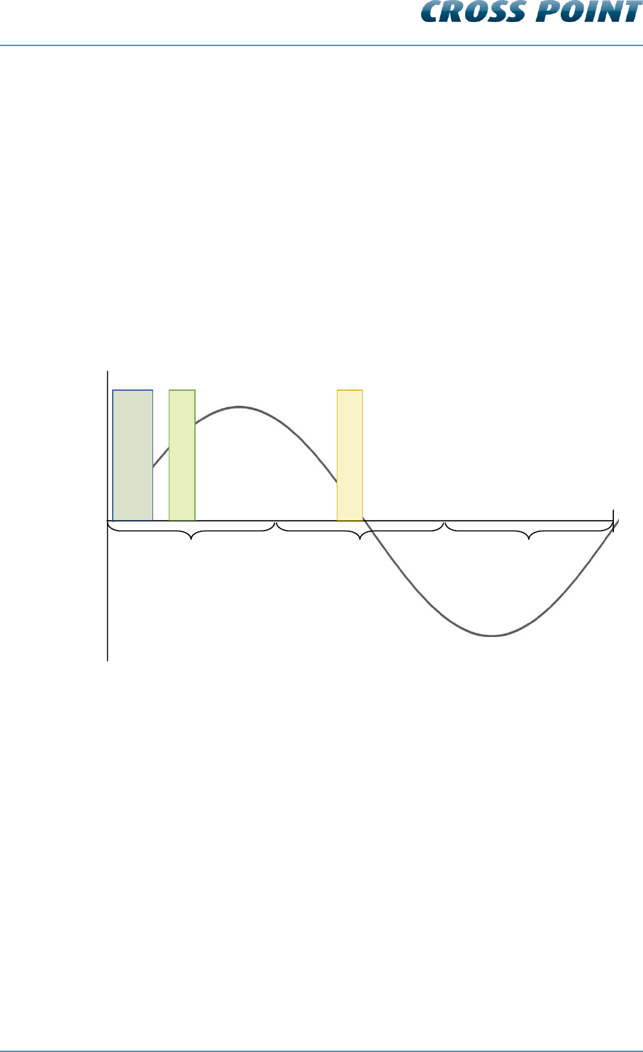
5 AM operating principle
The AM system operates on the pulse-listening principle. Using the zero crossing of the
50Hz mains frequency as a trigger, a short burst of 58kHz signal is transmitted and a
receiver window is ‘opened’ after the transmission burst has stopped.
If a tag was present within detection range during the transmission burst, the resonance
of this tag will be detected in the receiver window and an alarm will be triggered.
A single 50Hz mains frequency cycle is dived into three phases; phase A, B and C. Each
phase covers 1/3 of the 50Hz cycle duration.
A noise reference window is opened to detect the environmental noise. This signal is
compared with the signal received in the receiver window and allows the software to
properly distinguish a tag signal from a noise signal.
Figure 1 shows the AM operating principle (at 50Hz, with a default delay of 200μs) during
one 50Hz cycle.
Figure 1: AM operating principle
Transmission burst
Receiver window
Reference window
Phase C
Phase B
Phase A
Technical Manual AM Systems
AM operating principle v4.4 Page 13 of 72
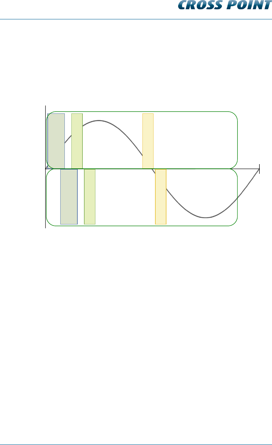
5.1 Synchronization principle
When multiple AM systems are installed in each other’s vicinity, it’s very important to
properly synchronize the transmission burst and receiver windows for all systems
involved. If systems are not properly synchronized they will create false alarms and poor
detection! Keep in mind that AM signals, when compared to other EAS technologies, can
“travel” quite far (up to 100m or more) because of their longer wavelength.
Figure 2 shows two AM systems that are not properly synchronized.
Figure 2: Two AM systems NOT synchronized
The transmission burst of system B starts later than the burst of system A, resulting in the
fact that system A is receiving the transmission burst of system B in its receiver window.
This might create false alarms and poor detection on system A, where system B will
function properly as the transmission burst of system A is not affecting the receiver
window of system B.
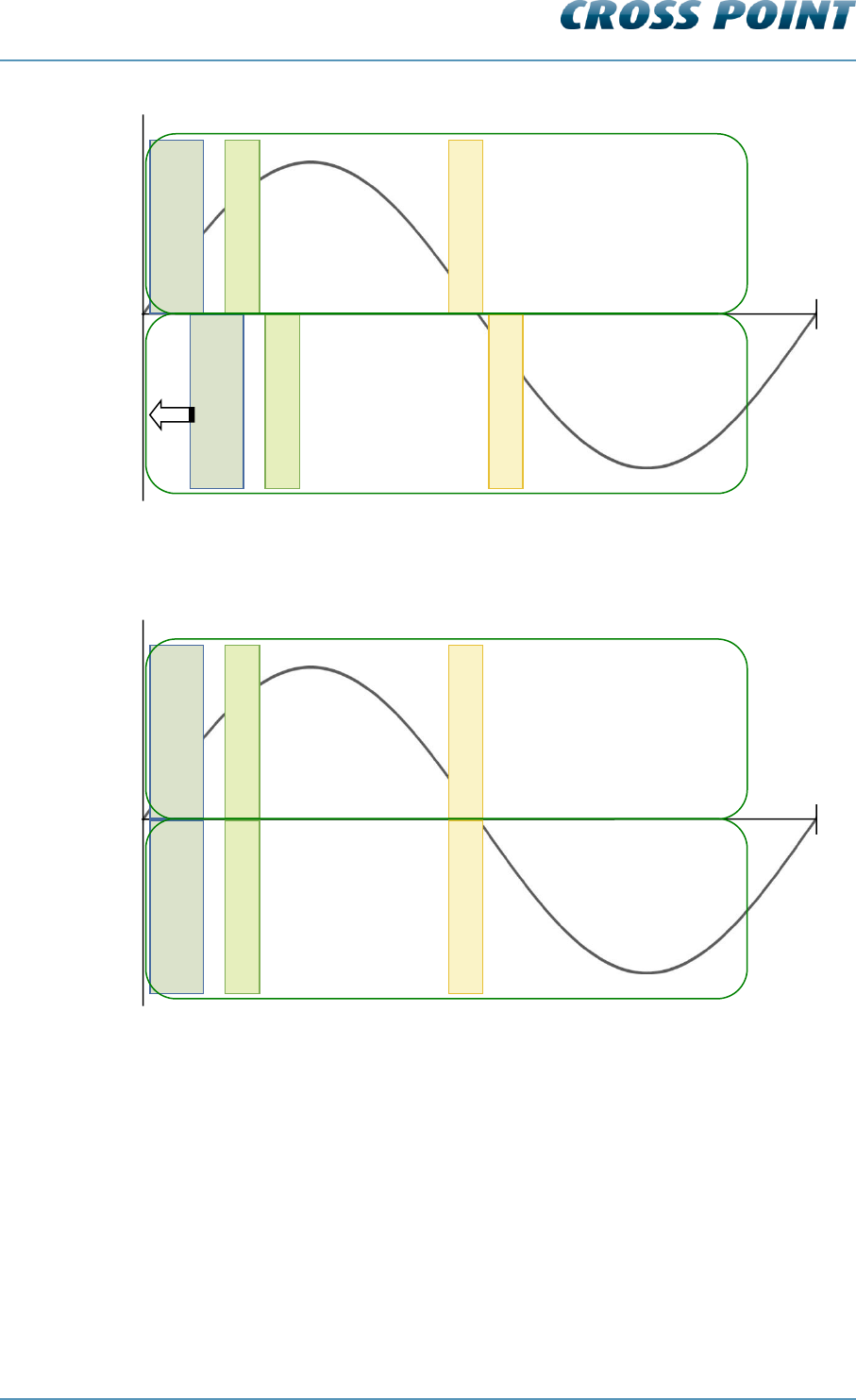
This problem can be solved by making sure that both systems transmit and receive at the
same moment, which can be realized by changing the delay time for one of the two
systems.
Example:
System A has currently a delay time of 0.2ms and system B a delay time of 1.4ms. The
delay time of system B needs to be corrected to the delay time of system A (or vice
versa), so their mutual transmission burst and detection windows will overlap each other
(see Figure 3). This will result in both systems working properly without interference (see
Figure 4).
Transmission burst
Receiver window
Reference window
20ms
0ms
Transmission burst
Receiver window
Reference window
System A
System B
50Hz mode
Technical Manual AM Systems
AM operating principle v4.4 Page 14 of 72
Figure 3: Correcting the delay time of system B
Figure 4 shows two AM systems that are properly synchronized.
Figure 4: Two AM systems properly synchronized
The synchronization can be performed by making use of Cross Point’s software. The
exact synchronization procedures are described in chapter 8.7.5.2.
Transmission burst
Receiver window
Reference window
20ms
0ms
Transmission burst
Receiver window
Reference window
System A
System B
50Hz mode
Transmission burst
Receiver window
Reference window
20ms
0ms
Transmission burst
Receiver window
Reference window
System A
System B
50Hz mode
Technical Manual AM Systems
Connections v4.4 Page 15 of 72
6 Connections
In the following chapters the connections between the TRX board, RX board and
Controller are described.
Furthermore the Printed Circuit Boards (PCB) and the manual adjustments are explained.
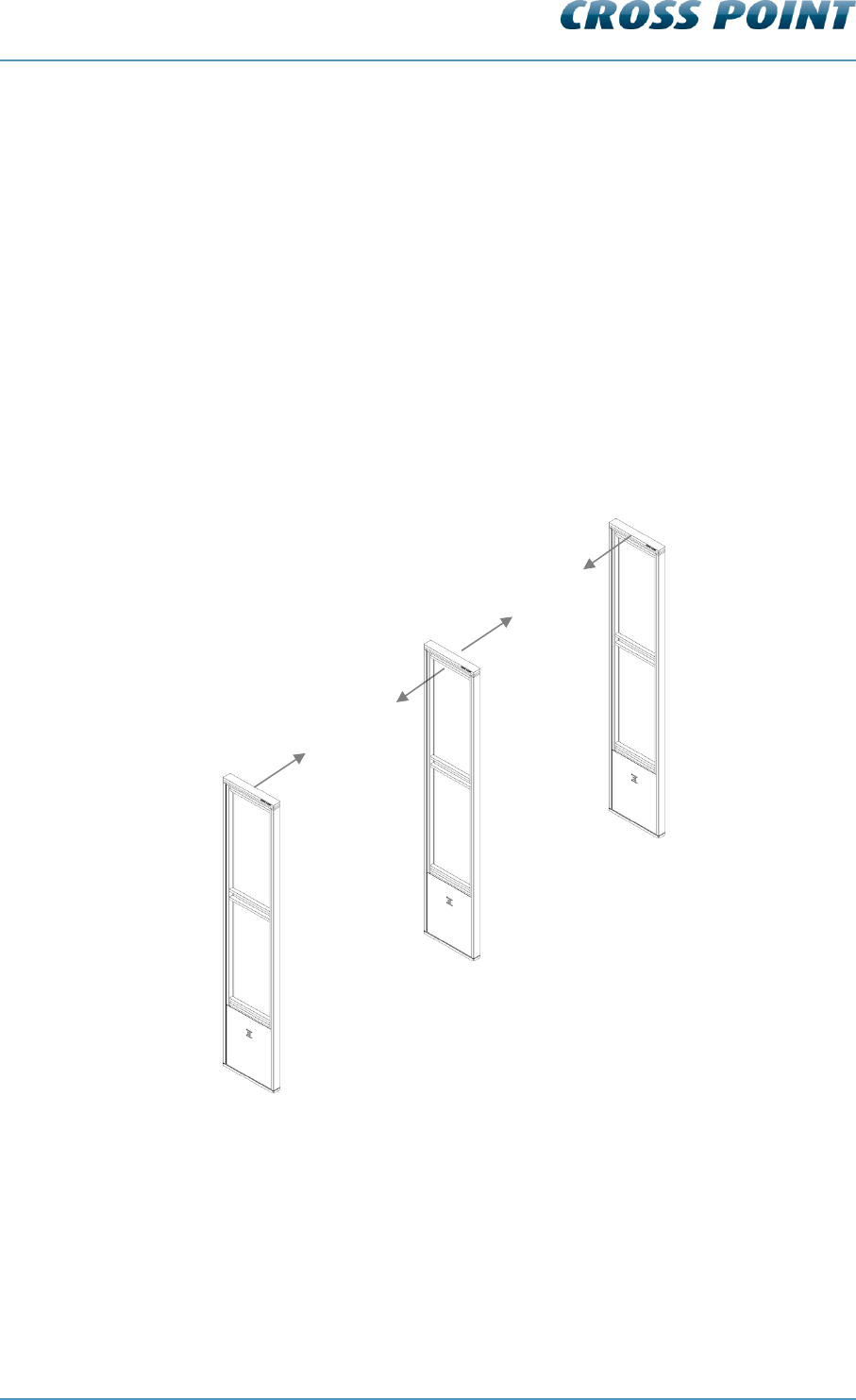
6.1 “A” and “B” side of the antenna
The antenna has a front side (A) and a back side (B). These sides are indicated on the
visitor counter in the top/middle of the antenna.
The A-side is the side on which the electronic boards can be accessed.
When using the visitor counter (see also chapter 6.12 (page 34)) try to put all antenna’s in
the AB-AB pattern, i.e. all antennas should be placed in the same way.
Figure 5: Antenna AB-AB pattern
Side B
Side B
Side A
Side A
RX1
RX2
TRX1

Technical Manual AM Systems
Connections v4.4 Page 16 of 72
6.2 How to access the electronic boards
In order to be able to access the electronic board, the top of the antenna needs to be
removed as well as the Plexiglas plate(s) and the metal front cover. Follow the next
procedure carefully to do this.
1. Put your left hand on top of the top part
2. Put your right hand around the antenna frame on the right side of the antenna
3. While pushing the top part to the right with your left hand (1), push the top part up
upwards with the thumb of your right hand (2). This will unlock the magnets and
the ‘click’ locking mechanism and the top part can be removed
4. Slide the Plexiglas plate on side A of the antenna upwards. Out of safety reasons
is it strongly advised to remove this Plexiglas plate completely when servicing the
electronics. When this is not possible make sure the Plexiglas plate is supported
properly after it is moved upwards, to prevent it from falling down and causing an
injury.
5. Unlock the screws in the front cover (side A)
6. Remove the front cover
1
2
Technical Manual AM Systems
Connections v4.4 Page 17 of 72
6.3 Field Bus connections
The TRX and RX antennas are interconnected through the Field Bus by using preferably
FTP cables, because FTP has an advantage to eliminate noise because of the extra
shielding.
The Cross Point Field Bus requires the devices to be connected in a
“daisy chain” connection. A “star” network is not allowed and will result
in poor communication between the devices and the host computer or
controller!
Each device (TRX PCB and RX PCB) has a unique address. This address is factory set
and cannot be changed. A PC/laptop enables local maintenance of the TRX and RX
boards by using the Device Explorer software.
When the Field Bus is connected to the Access Point and the Access Point is connected
to a Local Area Network (LAN), local servicing and data retrieval is possible. When an
Internet connection is available, the Access Point can also be connected to the Internet,
which enables service and data retrieval from any remote location over the Internet.
6.3.1 Bus connections with laptop
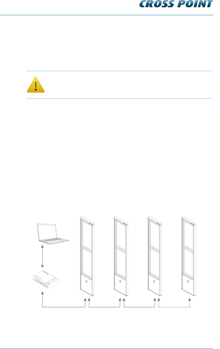
Figure 6 shows the Field Bus structure between the various antennas.
Connecting the Field Bus to a laptop (through an Access Point), allows on-site
maintenance through the Device Explorer software.
See chapter 0 for further information on how to use the Device Explorer software.
Figure 6: Field Bus structure
Ant. 1 Ant. 2 Ant. 3 - - - - Ant. n (max. 127)
FTP
FTP
FTP
Device Explorer
FTP
Ethernet
CrossCONNECT
Access Point
Technical Manual AM Systems
Connections v4.4 Page 18 of 72
6.4 Field Bus termination
For the Field Bus to operate properly the bus needs to be terminated on the first device
and the last device in the bus.
When an antenna is either the first or the last device in the Field Bus, then the bus needs
to be terminated on that device.
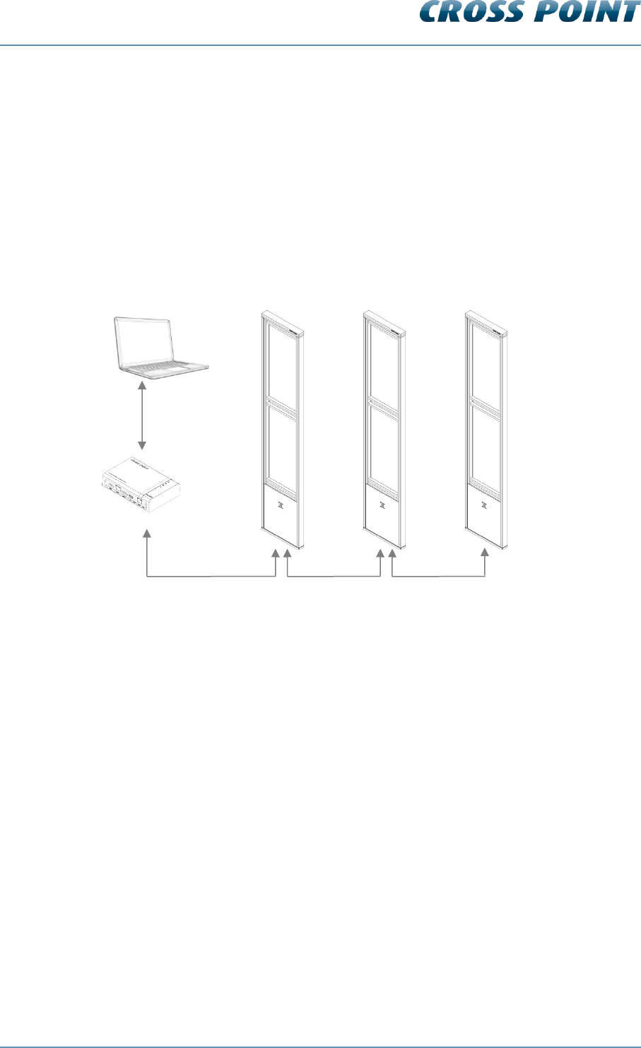
In the example in Figure 7 the bus needs to be terminated on the Access Point (which is
automatically done by the Access Point itself) and on RX2.
Figure 7: Field Bus termination example
6.4.1 TRX bus termination
Switch TERM to ON to terminate the bus on the TRX.
6.4.2 RX bus termination
Switch TERM (SW1) to ON to terminate the bus on the RX.
Device Explorer
Ethernet
Terminate Field bus
on this device!
RX1
TRX1
RX2
CrossCONNECT
Access Point
Field bus
automatically
terminated
Technical Manual AM Systems
Connections v4.4 Page 19 of 72
6.5 Power supply unit AM systems
The next sections contain information on power supply for AM systems. Please read the
supplied information carefully prior to connecting the power supply, as it contains
important information on proper usage of the power supply unit.
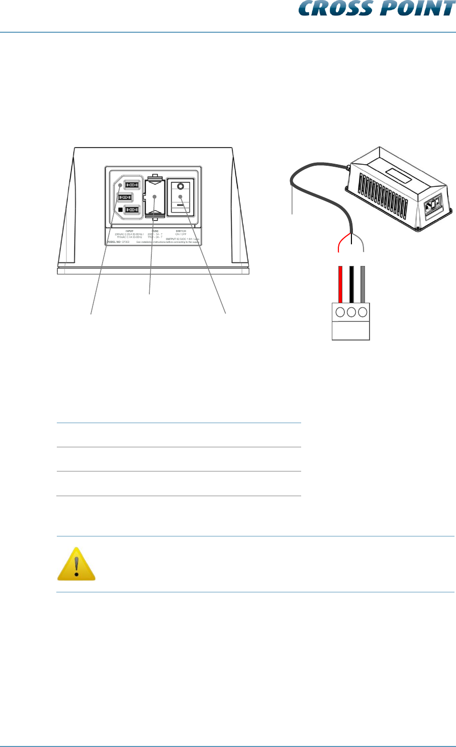
Figure 8: AM power supply unit
Table 1 shows the color schemes for the output cable.
Wire coloring variations for output cable
32.5VDC
Red
GND
Black
SYNC
Grey
Table 1: Output cable color scheme
The mains socket-outlet shall be installed near the power supply unit
and shall be easy accessible.
Output cable
ON/OFF switch
External fuse
Mains input
sync
+
GND
TRX board
connector

Technical Manual AM Systems
Connections v4.4 Page 20 of 72
6.6 Power supply specifications
Table 2 shows the specifications of the AM Power Supply.
Technical specifications
Dimensions (L x W x H)
227 x 108 x 71 mm
Weight
2.1 kg
Input voltage, frequency & current
230VAC 50-60Hz 500mA
or
115VAC 50-60Hz 1A
Mains inlet type
Fused AC IEC with ON/OFF switch
Mains lead
Euro Schuko to IEC, 1.5m length
Output
32.5VDC 1.6A + synchronization signal
Output cable
3x1mm2, fixed, 5m length. This cable can be
extended to 15m using a 3x1mm2 cable or
thicker.
Temperature range
0 – 50oC
External fuse
Replace when changing mains voltage!
230VAC – 1A slow
115VAC – 2A slow
Table 2: AM Power supply specifications
6.7 Switching to a different mains voltage
The power supply supports 2 mains voltages; 230VAC (default setting) and 115VAC.
By default the power supply is set to 230VAC mains input, but if required, the mains input
can be switched to 115VAC. Follow the next steps to switch to a different mains voltage:
1. Disconnect from mains power and carefully open the power supply housing
2. Locate the internal switch and switch it to the required position
3. Replace the external fuse with the correct value (see Table 2)
4. Carefully close the power supply housing
6.8 Power supply restrictions
This power supply has the following restrictions which must be respected carefully in
order to warrant the safety of the product and user:
Only to be used in combination with AM systems
For indoor use only
Disconnect from mains power before opening the housing
Do not cover the ventilation holes of the housing
Technical Manual AM Systems
Connections v4.4 Page 21 of 72
Leave at least 10cm of free space around the PSU for ventilation purposes
Allow for free air flow around the PSU
Local laws and regulations must be respected when installing and servicing this
device
Minimum distance between PSU and AM system is 1m.
It is prohibited to connect more than one TRX to a power supply. Use a
separate power supply for each TRX antenna!
Keeping the power supply principle in mind, the following power supply connections are
recommended:
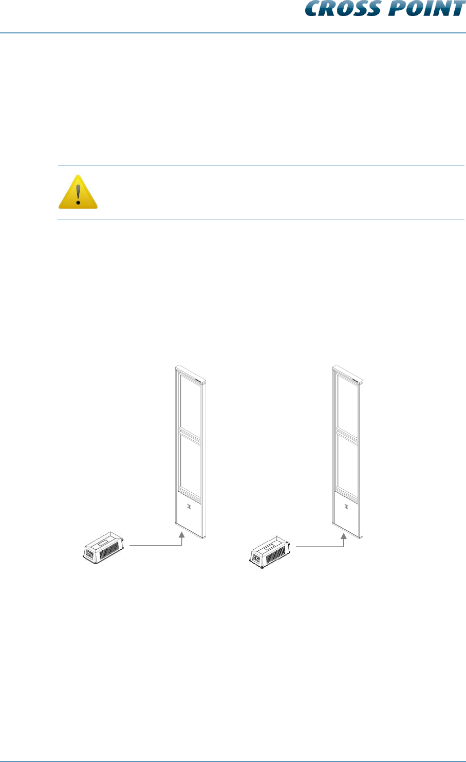
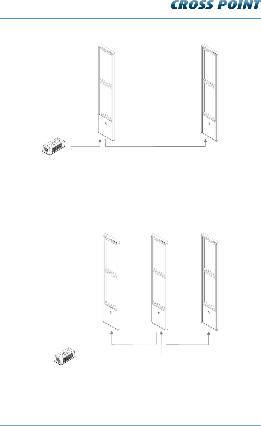
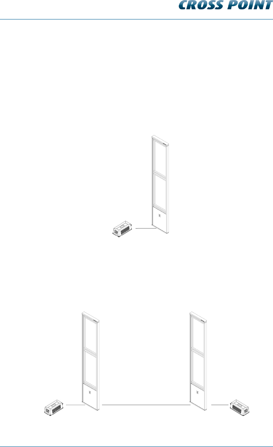
6.8.1 Power supply for a single system (mono)
In a single antenna system setup (1 or multiple transceivers), a power supply must be
connected to each individual TRX antenna. It is not possible to connect more than one
TRX to one power supply.
Figure 9: Power supply connection: Single and multiple mono antennas
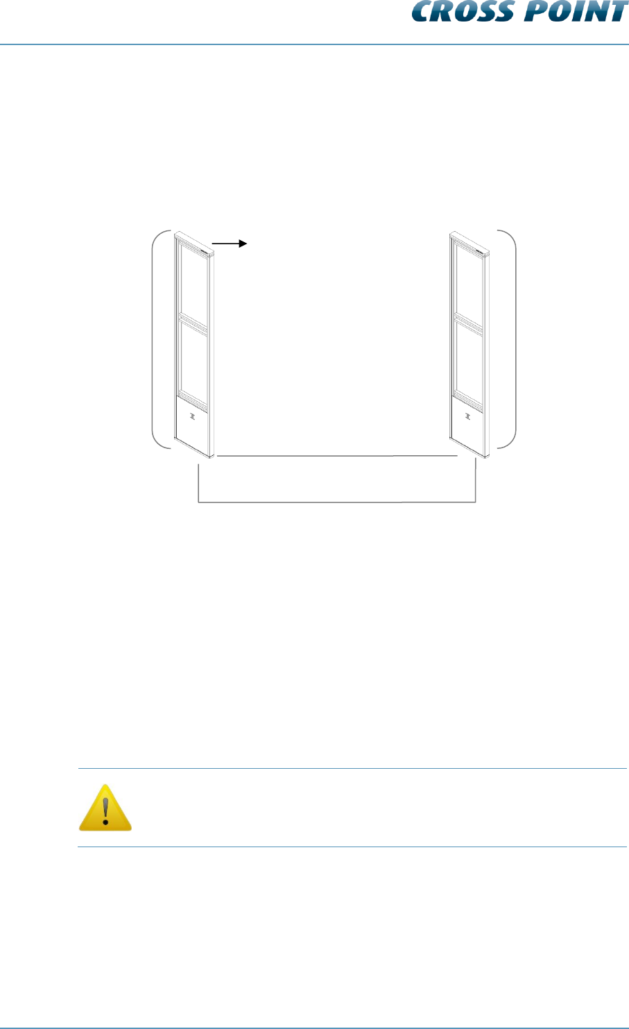
6.8.2 Power supply for a dual system
In a dual antenna system setup (1 TRX and 1 RX), a power supply must be connected to
each individual TRX antenna. It is not possible to connect more than one TRX to one
power supply.
TRX1
PSU
TRX2
PSU
Technical Manual AM Systems
Connections v4.4 Page 22 of 72
Figure 10: Power supply connection: Dual antenna system
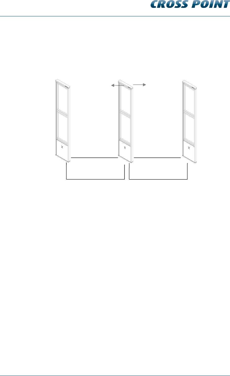
6.8.3 Power supply for a triple system
In a triple antenna system setup (1 TRX and 2 RX), a power supply must be connected to
each individual TRX antenna. It is not possible to connect more than one TRX to one
power supply.
Figure 11: Power supply connection: Triple antenna system
TRX
PSU
RX
Power supply through Field Bus
PSU
Power supply
through FTP
Power supply
through FTP
Power supply input
TRX
RX2
RX1
Technical Manual AM Systems
Connections v4.4 Page 23 of 72
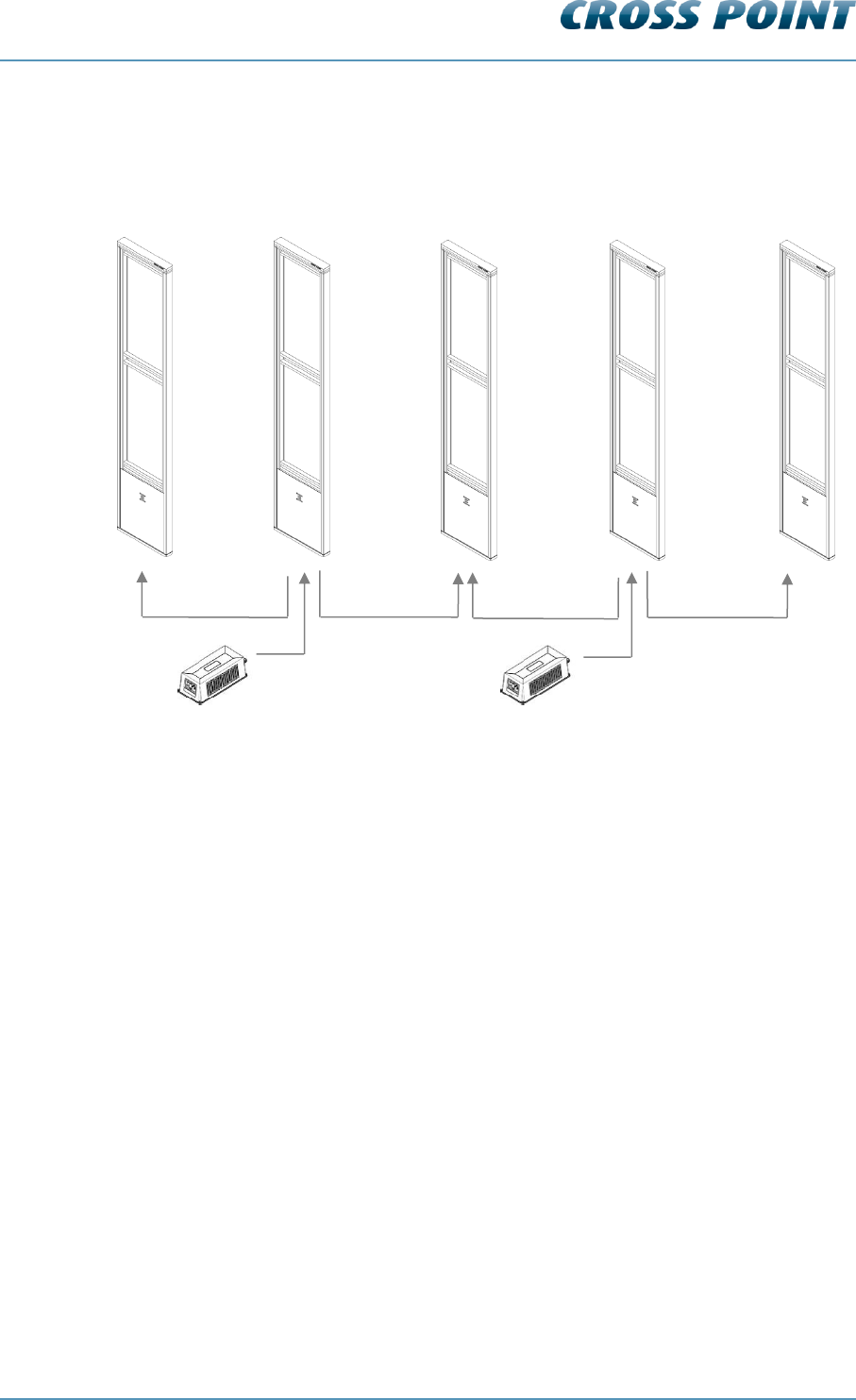
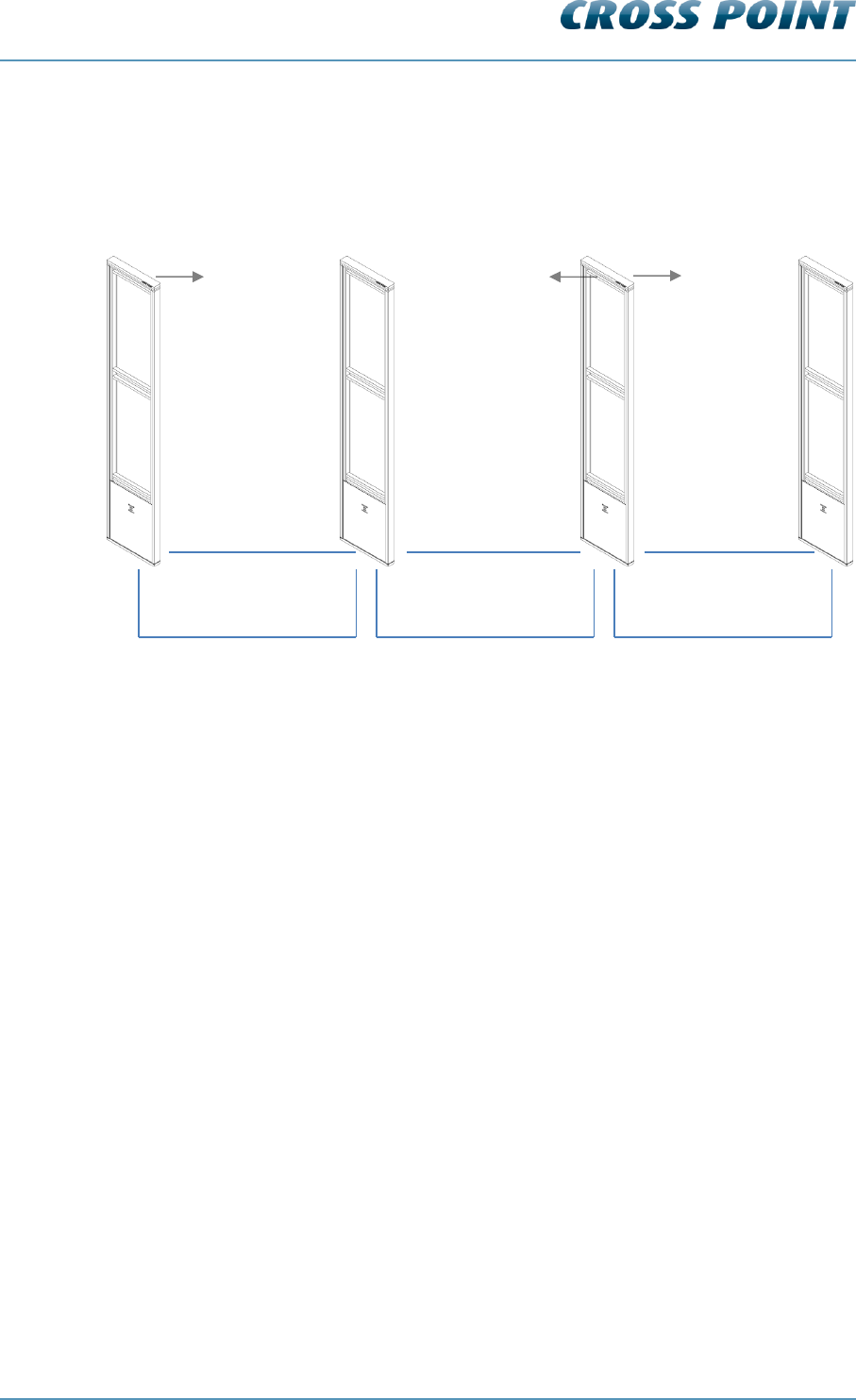
6.8.4 Power supply for large system setup
Figure 12 shows an example for 5 antenna power supply. Each additional TRX antenna
has to be powered with a separate power supply.
Figure 12: Power supply connections for more than 3 antennas
Power supply
through FTP
Power supply
through FTP
TRX1
RX1
PSU
Power supply
through FTP
TRX2
RX3
RX2
PSU
Power supply
through FTP
Technical Manual AM Systems
Connections v4.4 Page 24 of 72
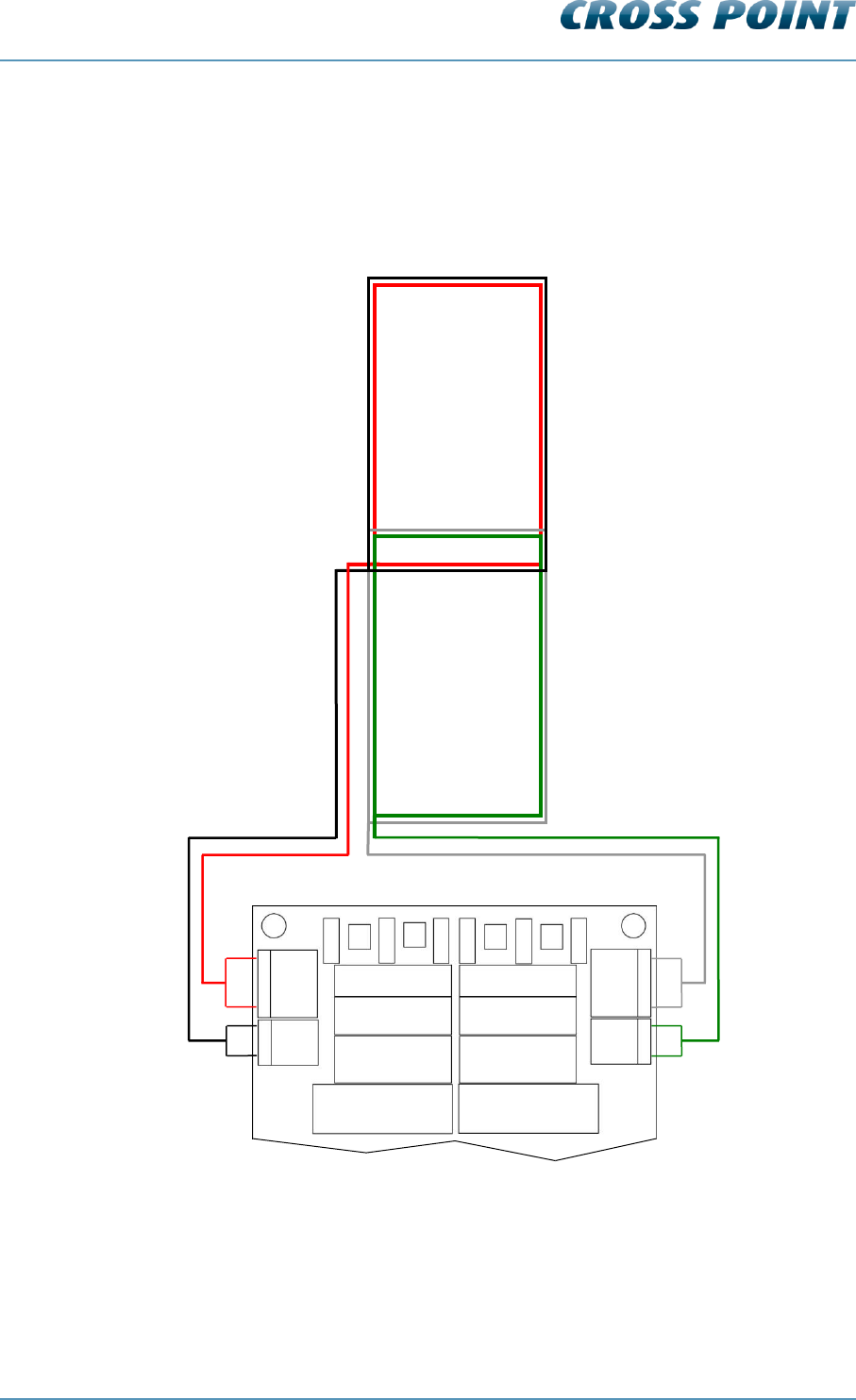
6.9 Antenna wiring
The AM TRX and RX antennas are configured with two identical antenna coil assemblies,
one in the top and the second in the bottom of the antenna. Each coil assembly consists
of two multi-turn coils (red wire and black wire in the top, green wire and white wire in the
bottom).
Figure 13: TRX antenna wiring
ANT
BOT2
ANT
BOT1
TUNE TOP1
TUNE TOP2
TUNE TOP3
TUNE BOT3
TUNE BOT2
TUNE BOT1
TRX board
TOP COIL
BOTTOM COIL
black
red
white
green
ANT
TOP2
ANT
TOP1

Technical Manual AM Systems
Connections v4.4 Page 25 of 72
6.10 The AM Transceiver (TRX)
The AM TRX is a fully digital AM transmitter and receiver, designed to operate at 58 kHz
and has the following features:
Center frequency of 58kHz
Real-time clock
Date/time stamped events are stored in onboard memory and can be retrieved
through software
External interfaces;
o push buttons
o buzzer
o relay
o LED’s
o tamper contact
Visitor counter connection
Internet connectivity, allowing remote servicing and data retrieval through use of
the CrossCONNECT Access Point.
Technical Manual AM Systems
Connections v4.4 Page 26 of 72
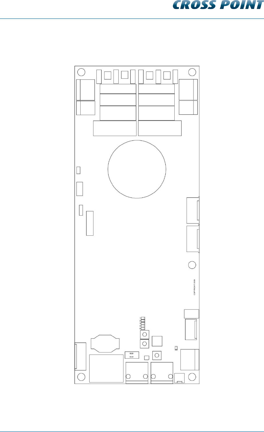
6.10.1 AM Transceiver Printed Circuit Board
Figure 14 shows the TRX PCB and its available components.
Figure 14: The AM TRX Printed Circuit Board
RELAY
REL1
MINI SD CARD
BAT
BUS A
BUS B
I/O’s
+
I/O2
I/O1
GND
SPEAKER
POWER
RESET
B2
B3
S1
LEDs
BUS A1
BUS B1
4
3
GND
2
1
VIS COUNT
TAMPER
BUZZER
ANT
BOT2
ANT
BOT1
ANT
TOP2
ANT
TOP1
TUNE TOP1
TUNE TOP2
TUNE TOP3
TUNE BOT3
TUNE BOT2
TUNE BOT1
D8
4
3
GND
2
1
1 2
ON
TERM

Technical Manual AM Systems
Connections v4.4 Page 27 of 72
TRX PCB Components 6.10.1.1
Table 3 shows the AM TRX components and a description of their function.
Component
Function
ANT BOT1
ANT BOT2
Bottom transmitter/receiver antenna loop
Bottom signal suppression loop
ANT TOP1
ANT TOP2
Top transmitter/receiver antenna loop
Top signal suppression loop
B2
Push button
B3
Push button
BAT
Backup battery for internal clock.
BL1
LED indicator. Blinks during start-up of the TRX board and
in case the TRX board has no connection with a host when
connected to the Field Bus. Lights up continuously when a
connection with a host has been established.
BUS A
Field Bus A connector for RJ45 connection. Allows the
board to be connected in the Field Bus structure.
BUS A1
Analogue connection to the receiver. Relates to BUS A
connector.
BUS B
Field Bus B connector for RJ45 connection. Allows the
board to be connected in the Field Bus structure.
BUS B1
Analogue connection to the receiver. Relates to BUS B
connector.
BUZZER
On-board buzzer for alarm notifications
D8
LED indicator. Lights up when a power supply is connected
and switched on.
I/O’s
Programmable input/output. Allows connection of external
devices like camera’s, push buttons, buzzers, etc.
LEDs
LED array, indicates various system settings.

Technical Manual AM Systems
Connections v4.4 Page 28 of 72
MINI SD CARD
Mini SD card slot. An SD card containing special audio
notification messages can be inserted. For future use.
POWER
External power supply input connector.
REL1
The actual relay.
RELAY
The external connection for relay REL1. Normally Open
(NO), Common (COM) and Normally Closed (NC) potential
free contacts are available to connect external devices like
camera’s, buzzers, etc.
Relay max. rating: 30VDC/1A
RESET
Reset button. Pressing this button will result in a software
reset of this board without interrupting the Field Bus.
S1
Rotary switch for selecting one of the following options:
0. Default active
1. Test mode
All other positions of this rotary switch are not used.
SPEAKER
External loudspeaker connection. Allows audio files to be
played (only in combination with the mini SD card).
TAMPER
External tamper connector.
Allows connection of a mechanical switch to detect
unauthorized opening of the antenna housing.
NOTE: Not implemented yet in the antenna housing.
TERM
Field Bus termination switch.
The Field Bus needs to be terminated properly to avoid
signal reflections which can cause bad communication. The
first and last device in the Field Bus structure need to
terminate the bus. Switch to ON if this TRX is the first or
last device in the Field Bus.
TUNE BOT1
TUNE BOT2
TUNE BOT3
Pluggable bridge positions to tune the TRX transmitter
bottom antenna loop signal to maximum value
TUNE TOP1
TUNE TOP2
TUNE TOP3
Pluggable bridge positions to tune the TRX transmitter top
antenna loop signal to maximum value

Technical Manual AM Systems
Connections v4.4 Page 29 of 72
VIS COUNT
Visitor counter connector.
Connect the wire to the visitor counter to this connector.
Table 3: The AM TRX components
Technical Manual AM Systems
Connections v4.4 Page 30 of 72
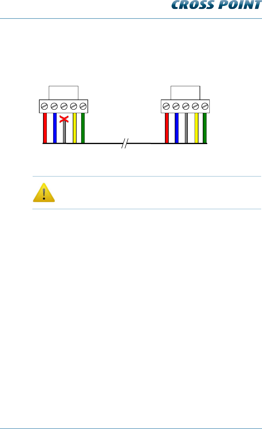
6.10.2 Transceiver - receiver cable connections
When an AM receiver is combined with an AM transceiver, the receiver must be
connected to the transceiver with the receiver cable. Figure 15 shows the transceiver to
receiver cable connections.
Figure 15: Receiver cable connections
Make sure that the shielding of the wire is only connected on the
receiver side, NOT on the transceiver side!
TRANSCEIVER SIDE
(shielding not connected!)
green
yellow
shield
blue
red
RECEIVER SIDE
green
yellow
shield
blue
red
Technical Manual AM Systems
Connections v4.4 Page 31 of 72
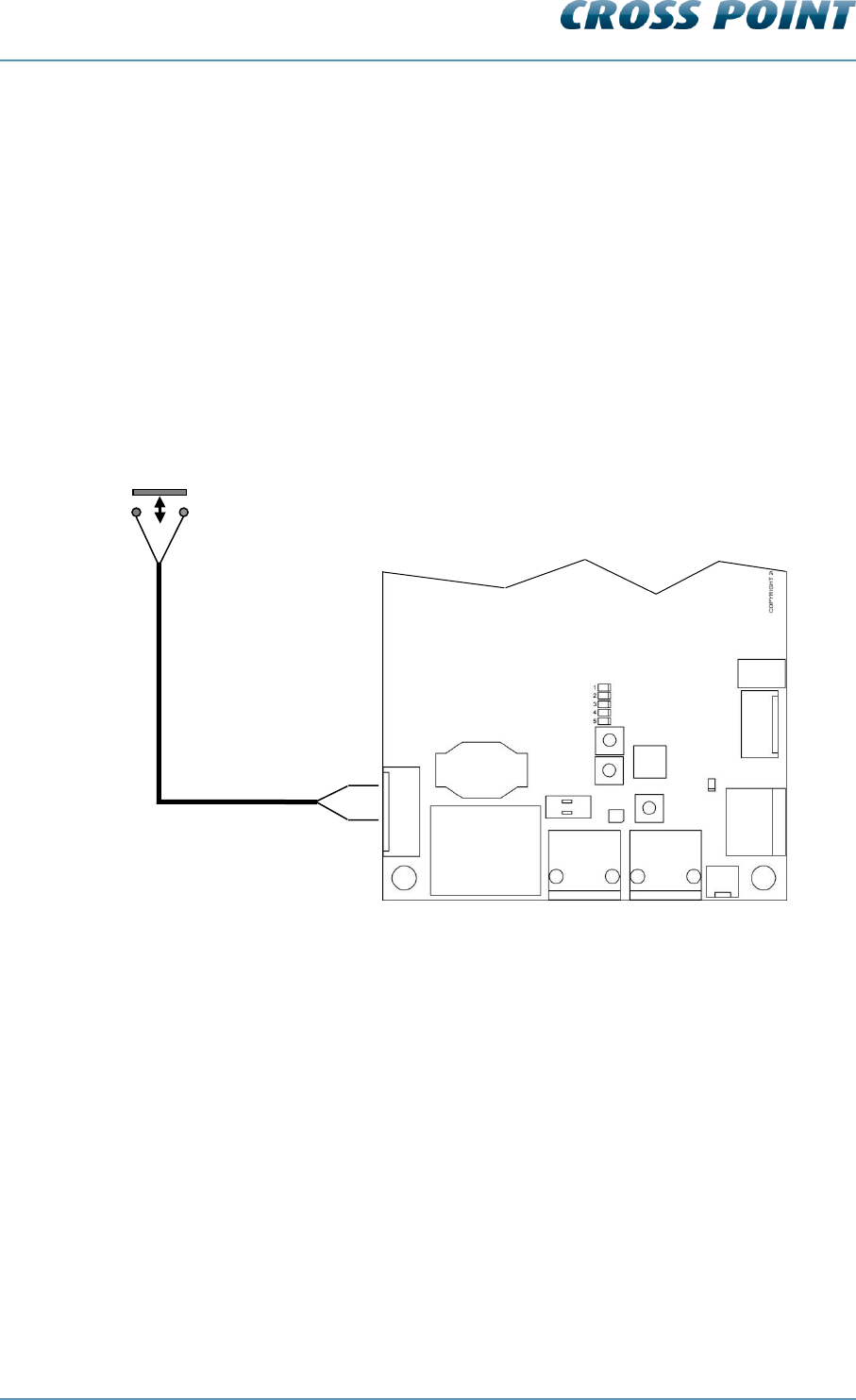
6.10.3 I/O connections
The AM TRX board is equipped with two I/O’s which can be used for connecting a
pushbutton (Forced Alarm option) or as output for other external devices (e.g. camera).
To avoid interference, caused by the wires which will be connected to any of the I/O’s, it
is very important to only connect the wires to the I/O connector contacts.
Do not connect any of the wires directly to a GND contact on the TRX board or on
the power supply! Use the “GND” connector to connect to the ground.
The I/Os have a current limit of 70mA. Do not connect devices to the I/Os that draw more
than 70mA, else the I/O drivers will get damaged!
Figure 16 shows the proper way to connect a “Forced Alarm” pushbutton between “I/O1”
and “+”.
Figure 16: Proper I/O connections
+
I/O2
I/O1
GND
FTP
TRX board
Technical Manual AM Systems
Connections v4.4 Page 32 of 72
6.11 The AM Receiver (RX)
The AM Receiver can be connected to the AM Transceiver to enhance the detection
range. All information and events are stored on the transceiver, not on the receiver board
itself.
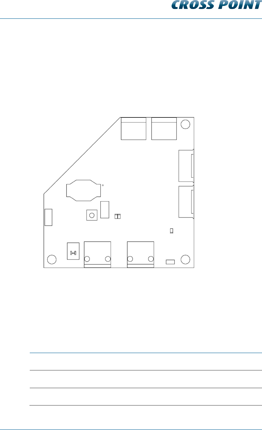
6.11.1 AM Receiver Printed Circuit Board
Figure 17 shows the RX PCB and its available components.
Figure 17: The AM RX Printed Circuit Board
RX PCB Components 6.11.1.1
Table 4 shows the AM RX components and a description of their function.
Component
Function
ANT BOT
Bottom receiver antenna loop
ANT TOP
Top receiver antenna loop
BAT
Backup battery for internal clock.
VIS COUNT
BAT
RESET
D7 D8
BUS A
BUS B
TAMPER
POWER
BUS A1
BUS B1
ANT TOP
ANT BOT
TERM

Technical Manual AM Systems
Connections v4.4 Page 33 of 72
BUS A
Field Bus A connector for RJ45 connection. Allows the board to be
connected in the Field Bus structure.
BUS A1
Analogue connection to the transceiver.
BUS B
Field Bus B connector for RJ45 connection. Allows the board to be
connected in the Field Bus structure.
BUS B1
Analogue connection to the transceiver.
D7
Red LED. ON (blinking) when the receiver is in bootloader mode
(e.g., during firmware upload). OFF during normal operation.
D8
Green LED. ON indicates a connection with a host
computer/controller. OFF indicates that the connection with the host
is lost.
POWER
LED indicator. Lights up when power supply is received through the
Field Bus.
RESET
Reset button. Pressing this button will result in a software reset of
this board without interrupting the Field Bus.
TAMPER
External tamper connector.
Allows connection of a mechanical switch to detect unauthorized
opening of the antenna housing.
NOTE: Not implemented yet in the antenna housing.
TERM
Field Bus termination switch.
The Field Bus needs to be terminated properly to avoid signal
reflections which can cause bad communication. The first and last
device in the Field Bus structure need to terminate the bus. Switch to
ON if this RX is the first or last device in the Field Bus.
VIS COUNT
Visitor counter connector.
Connect the wire to the visitor counter to this connector.
Table 4: The AM RX components
Pins 3 and 6 of RJ-45 connector BUS A are not connected to pins 3 and
6 on RJ-45 connector BUS B. Unlike the RF systems, pins 3 and 6 are
not used as synchronization wires, but for communication between the
transceiver and receiver.
For this reason it is not allowed to connect RF and AM systems on the
same Field Bus!
Technical Manual AM Systems
Connections v4.4 Page 34 of 72
6.12 The visitor counter
The AM models can be equipped with a visitor counter. This counter allows counting of
visitors as well as determining the movement direction of a person who generated an
alarm.
Both TRX and RX antennas can therefore be equipped with a visitor counter PCB. The
TRX antenna holds the RX visitor counter PCB (IR-RX) and the RX antenna holds the TX
visitor counter PCB (IR-TX).
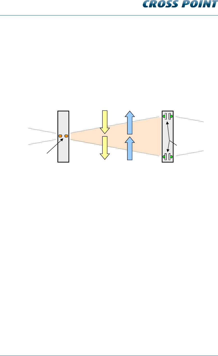
Figure 18 shows the visitor counter principle.
Figure 18: Top view of the visitor counter principle
The IR LED on side B of the RX antenna transmits an infra-red signal, which is received
by both IR receivers on side A of the TRX. When the infra-red signal is interrupted by a
person walking in (incoming), first IR-RX1 will receive no signal and then IR-RX2 will
receive no signal. In this way the visitor counter registers the movement direction. The
same principle is used for outgoing persons.
As shown in the above figure, each visitor counter PCB has an A and B side. The
transmitter IR-LED’s and the IR receivers can be switched on or off per side. This is
necessary for each first and last antenna in a row. For example, if the system in the
above figure consists just of two antennas, then the visitor counter side B of the
transceiver antenna and side A of the receiver antenna must be switched off. The Device
Explorer software will automatically activate the visitor counters dependent of the antenna
lay-out.
It is possible to increase the intensity of the IR-LED’s. This can be useful in bright and
sunny environments, to ensure proper functioning of the visitor counter.
For the visitor counter to operate properly the minimum distance between the transceiver
and receiver is 0.5m. The maximum distance is 3m (per aisle).
visitor counter PCB (IR-TX)
visitor counter PCB (IR-RX)
IR LED’s
IR Receivers
Side B
Side B
Side A
Side A
Incoming
IR-RX1
IR-RX2
Outgoing
Technical Manual AM Systems
Connections v4.4 Page 35 of 72
6.13 Various connections
For proper operation of the AM system, it is very important to interconnect the
transceivers and receivers in the correct way. This chapter shows and explains these
various connections.
6.13.1 Single antenna system (no aisle)
The AM system can be used as a single antenna system (mono). When no receivers are
connected to the transceiver, the transceiver will automatically function as a mono
antenna system. Visitor counting is not possible.
Figure 19: Single antenna system
Multiple transceivers 6.13.1.1
In case only transceivers are used, the transceivers can either be used as complete
stand-alone antennas, or they can be interconnected with FTP cables to create the Field
Bus. Connecting the Field Bus to a computer or controller will allow central (remote)
maintenance and reports to be generated. Visitor counting is not possible.
Figure 20: Transceivers only with FTP connection
PSU
TRX1
TRX1
TRX2
FTP
PSU
PSU
Technical Manual AM Systems
Connections v4.4 Page 36 of 72
6.13.2 Dual antenna system (single aisle)
In case receivers are connected to the transceiver it is of great importance to connect the
FTP and analogue connection cables to the proper connectors on the TRX and RX
boards.
Figure 21 shows the connections for a dual system (TRX + RX).
Figure 21: Dual antenna system connections
Backfield control 6.13.2.1
When only one receiver antenna is connected to a transceiver and this receiver is
connected to Bus A of the transceiver, then the detection of the B-side of the transceiver
can be reduced if required. This is called ‘Back field control’.
When enabled, back field control makes it possible to reduce the back field detection of
the TRX antenna by switching of its internal receiver circuit. The TRX antenna will then
act as a transmitter only and detection is on the RX antenna only, resulting in a
concentrated detection area between the antennas.
Backfield control is only possible on a transceiver, not on a receiver!
How to enable/disable back field detection is described in chapter 0.
Power supply connections are not shown in the image but are described in 6.5.
TRX
RX
BUS A1
BUS B1
BUS A
BUS B
FTP
Receiver cable
Back field
control
Aisle 1
No back
field control
Side A
X
Technical Manual AM Systems
Connections v4.4 Page 37 of 72
6.13.3 Triple antenna system (double aisle)
In case receivers are connected to the transceiver it is of great importance to connect the
FTP and analogue connection cables to the proper connectors on the TRX and RX
boards. Figure 22 shows the connections for a triple system (RX + TRX + RX).
Figure 22: Triple antenna system connections
In this system setup it is important that the FTP cable is connected to the proper bus to
allow for the receiver lights to light up in case of an alarm. The receiver FTP cable has to
be inserted into the transceiver board with reference to the side (A or B) of the transceiver
on which the particular receiver is installed.
Figure 22 shows receiver RX1 installed on the backside (side B) of transceiver TRX1.
The FTP cable for RX1 then needs to be plugged into the BUS B connector of TRX1.
RX2 is installed in front (side A) of TRX1 and the FTP cable for RX2 thus needs to be
plugged into the BUS A connector of TRX1.
Power supply connections are not shown in the image but are described in chapter 6.5.
TRX1
RX2
BUS A1
BUS B1
BUS A
BUS B
FTP
Receiver cable
RX1
BUS A1
BUS B1
BUS A
FTP
Receiver cable
BUS B
Aisle 1
Aisle 2
Side A
Side B
Technical Manual AM Systems
Connections v4.4 Page 38 of 72
6.13.4 Quad antenna system (triple aisle)
In case four or more AM antennas need to be installed as one complete system, all
antennas need to be connected as shown in Figure 23.
Figure 23: Quad antenna system
When a receiver is installed between two transceivers (RX1 in the above example), then
this receiver needs to be connected to both transceivers through the analogue receiver
cables to make this receiver detect tags in both aisle 2 and aisle 3.
Backfield control is possible on those transceivers that are the first and/or last antenna of
the row and the receiver is connected to BUS A of the transceiver. In this case the
backfield detection of TRX1 can be either enabled or disabled. Backfield control on TRX2
is not possible, since this antenna is installed between two receivers.
If no detection is required in aisle 2, then the receiver cable between TRX2 and RX1 can
be disconnected. Backfield control on TRX1 and TRX2 will then be possible, if required.
Power supply connections are not shown in the image but are described in chapter 6.5.
6.13.5 Large systems
Large systems (more than 4 antennas) need to be installed as described in the previous
section. If one complete Field Bus is required then all antennas need to be
interconnected with FTP cable.
RX1
TRX2
BUS A1
BUS B1
BUS A
BUS B
FTP
Receiver cable
BUS A1
BUS B1
BUS A
FTP
Receiver cable
BUS B
BUS A
BUS B
FTP
BUS A1
BUS B1
Receiver cable
RX2
Aisle 1
Aisle 2
Aisle 3
TRX1
Side A
Side A
Side B

Technical Manual AM Systems
Configuration v4.4 Page 39 of 72
7 Configuration
This chapter describes the recommended adjustment procedure for the AM transceiver
and receiver.
7.1 General connections
Refer to chapter 3.1 (page 9) for noise sources and installation guidelines.
Position the antenna(s) at the required location.
Connect the power supply to the power input of the TRX board
Connect the FTP cable between the RX and TRX board (in case of a multiple
antenna setup)
Connect the receiver cable between the RX and TRX board (in case of a multiple
antenna setup)
Switch on the power supply → the power LED’s on both the TRX and RX will light
up.
Wait for about 10 seconds for the system to start up.
7.2 TRX configuration settings
Although the TRX comes pre-configured with factory settings, it can be necessary to fine-
tune this board for best performance in your specific environment.
The TRX can be configured through the Field Bus using a host computer and the Cross
Point Device Explorer software.
7.3 TRX configuration – Device Explorer
Please refer to chapter 8.7.5.1 for further details on how to configure the TRX using the
Device Explorer software.
Technical Manual AM Systems
Cross Point Device Explorer v4.4 Page 40 of 72
8 Cross Point Device Explorer
This chapter covers the AM transceiver and receiver settings in combination with the
Cross Point Device Explorer software.
Please refer to chapter 2.2 for details on the Field Bus structure.
For the Cross Point Device Explorer installation procedure and other general settings we
refer to the Cross Point Device Explorer User Manual (download available at
www.crosspoint.nl).
Make sure to keep your laptop at least 3m away from the antennas. The
back light of the laptop screen can create a lot of noise and might
reduce the performance of the system!
8.1 Starting the Device Explorer
After having installed the Cross Point Device Explorer, go to
Start > All programs > Cross Point > Device Explorer
(or your, during installation specified, destination folder) to start the Device Explorer.
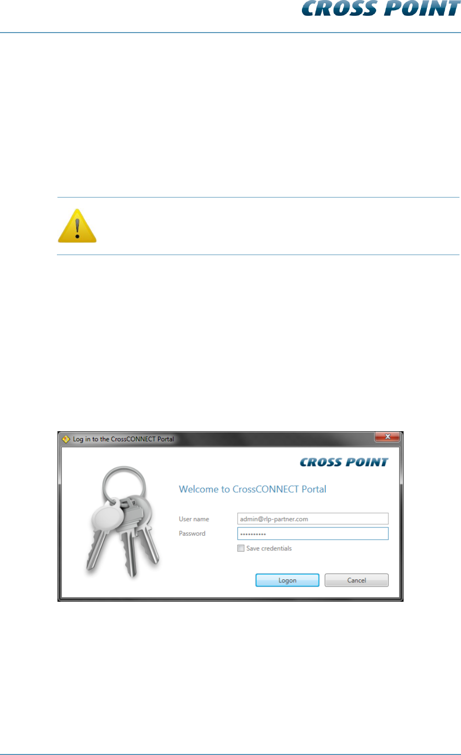
8.2 Logon to Device Explorer
After starting the Device Explorer, you will be prompted to enter your username and
password that allow you to use the Device Explorer.
Figure 24: Logon to Device Explorer
These credentials have been supplied to you by Cross Point or a partner of Cross Point.
Tick the “Save credentials” checkbox if you want to use the specified logon credentials
each time you start the Device Explorer.
Enter your credentials and click the Logon button to continue.
Technical Manual AM Systems
Cross Point Device Explorer v4.4 Page 41 of 72
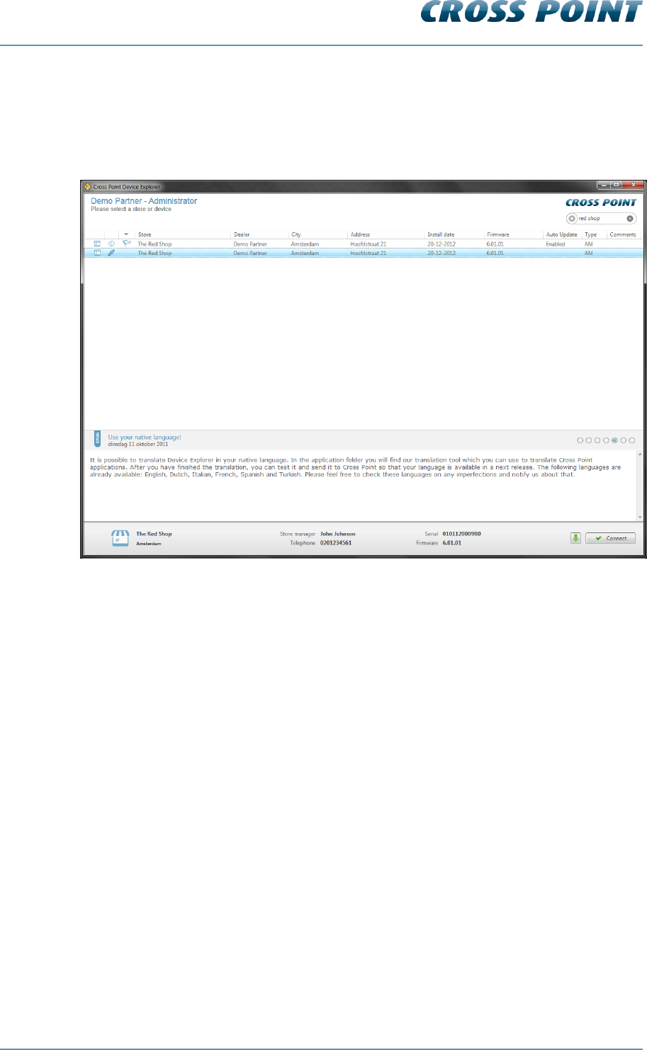
8.3 Store overview
When the Device Explorer is started and you have successfully logged-on, the Store
overview screen opens.
All Access Points that are available for you are shown in this screen.
Figure 25: Store overview
Select the required store from the Store overview screen through a double click on the
store to be able to perform local or remote service to the AM systems that are installed in
the selected store.
The next chapters will cover the specific transceiver and receiver properties and settings.
Please refer to the Cross Point Device Explorer User Manual for more information on how
to change settings for the Access Point itself.
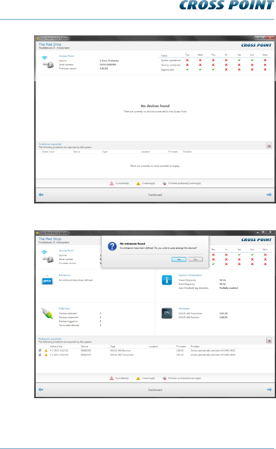
8.4 Dashboard
After a successful logon to the selected Access Point, the Dashboard for this Access
Point appears.
In case there are no devices connected yet to the Access Point, the Dashboard will show
the “No devices found” message. See Figure 26.
If there are any devices connected to the Access Point, but no entrances have been
created yet, the Dashboard will show the details as displayed in Figure 27.
In case devices are connected and entrances have been created, the Dashboard will
display details similar to those in Figure 28.
Technical Manual AM Systems
Cross Point Device Explorer v4.4 Page 42 of 72
Figure 26: Dashboard – No devices found
Figure 27: Dashboard – Devices found, no entrances found
Technical Manual AM Systems
Cross Point Device Explorer v4.4 Page 43 of 72
Figure 28: Dashboard – Devices and entrances found
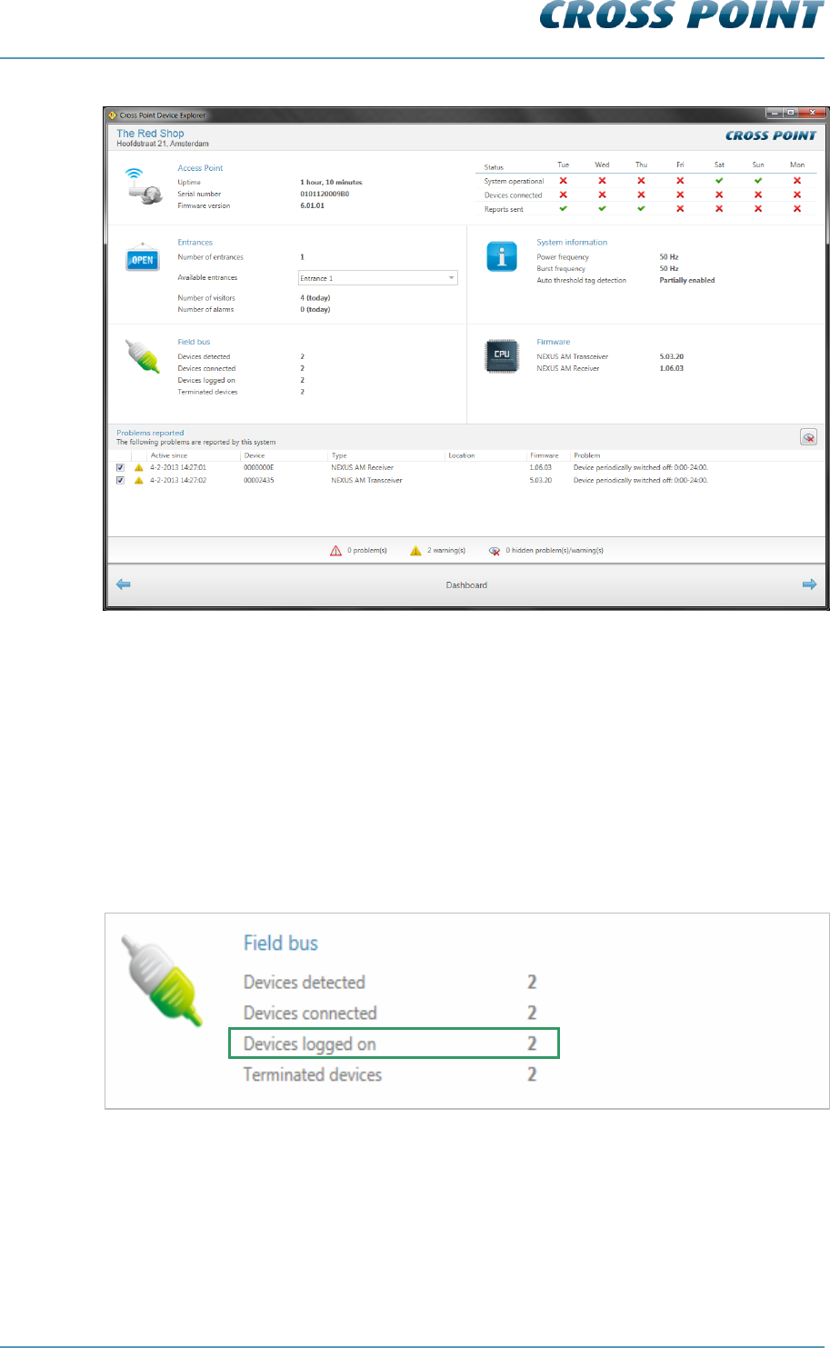
8.5 Logon to the connected devices
The AM devices are secured against unauthorized access by means of a special code,
the Installer Access code.
The Access Point logs-on to the devices using the Installer Access code. The Installer
Access code is automatically derived from your company´s dealer code and cannot be
customized anymore.
The Field Bus section shows if the logon to all detected devices was successful.
Figure 29: Dashboard – Fieldbus section - Logon status

Technical Manual AM Systems
Cross Point Device Explorer v4.4 Page 44 of 72
8.6 Creating entrances
If entrances have not yet been created and the Device Explorer shows the screen as
displayed in Figure 27, you can just click the Yes button to start the automatic antenna
arrangement on the Access Point.
Once the antenna arrangement procedure has finished, the Entrances section in the
Dashboard will show the number of entrances that were created, each individually
selectable entrance and the number of visitors and alarms for the selected entrance.
Figure 30: Dashboard – Entrances section
AM systems with integrated visitor counters can be arranged automatically using the
visitor counter sensors of each antenna. AM systems without integrated visitor counters
will be arranged in a “Best guess” entrance. This best guess situation may not represent
the actual system’s layout, in which case you will have to manually adjust the position of
these antennas.
Click on the Entrances section of the Dashboard to go to the Entrances page to start
configuring the created entrance(s).
Technical Manual AM Systems
Cross Point Device Explorer v4.4 Page 45 of 72
8.7 Configuring entrances
When the Entrances section is clicked in the Dashboard, the Entrances page is shown.
Figure 31: Entrances
The Entrances page is divided in 2 parts:
8.7.1 Entrances - Top part
The top part of the Entrances page consists of the following section:
Figure 32: Entrances – Top part
Main menu
Mute button
Button bar
3D view
Technical Manual AM Systems
Cross Point Device Explorer v4.4 Page 46 of 72
The Mute button enables you to switch off all buzzers on all devices at once. This is
useful when you are configuring the system and don’t want any loud alarms.
8.7.2 Main menu
The Main menu lets you quickly navigate to the other available sections of the Device
Explorer:
System – refer to paragraph 8.8 for further details
Access Point – refer to the Cross Point Device Explorer manual for further
details
8.7.3 3D antenna view
The 3D view shows the AM antennas that have been either automatically arranged or
manually inserted in the selected entrance.
When entering the Entrance page, the Normal view is activated by default and various
options for the selected entrance are available through the Entrance button bar.
Dependent of the selected button, the sub-buttons on the right of the Button bar will vary.
Paragraph 8.9 explains the various buttons available in the button bar.
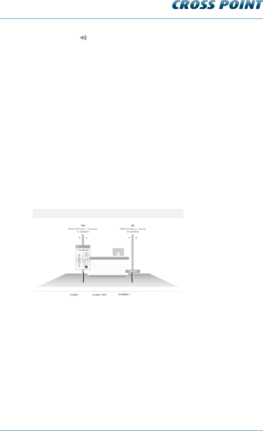
Normal view 8.7.3.1
Click this button to return to the normal 3D front view.
Figure 33: Normal view
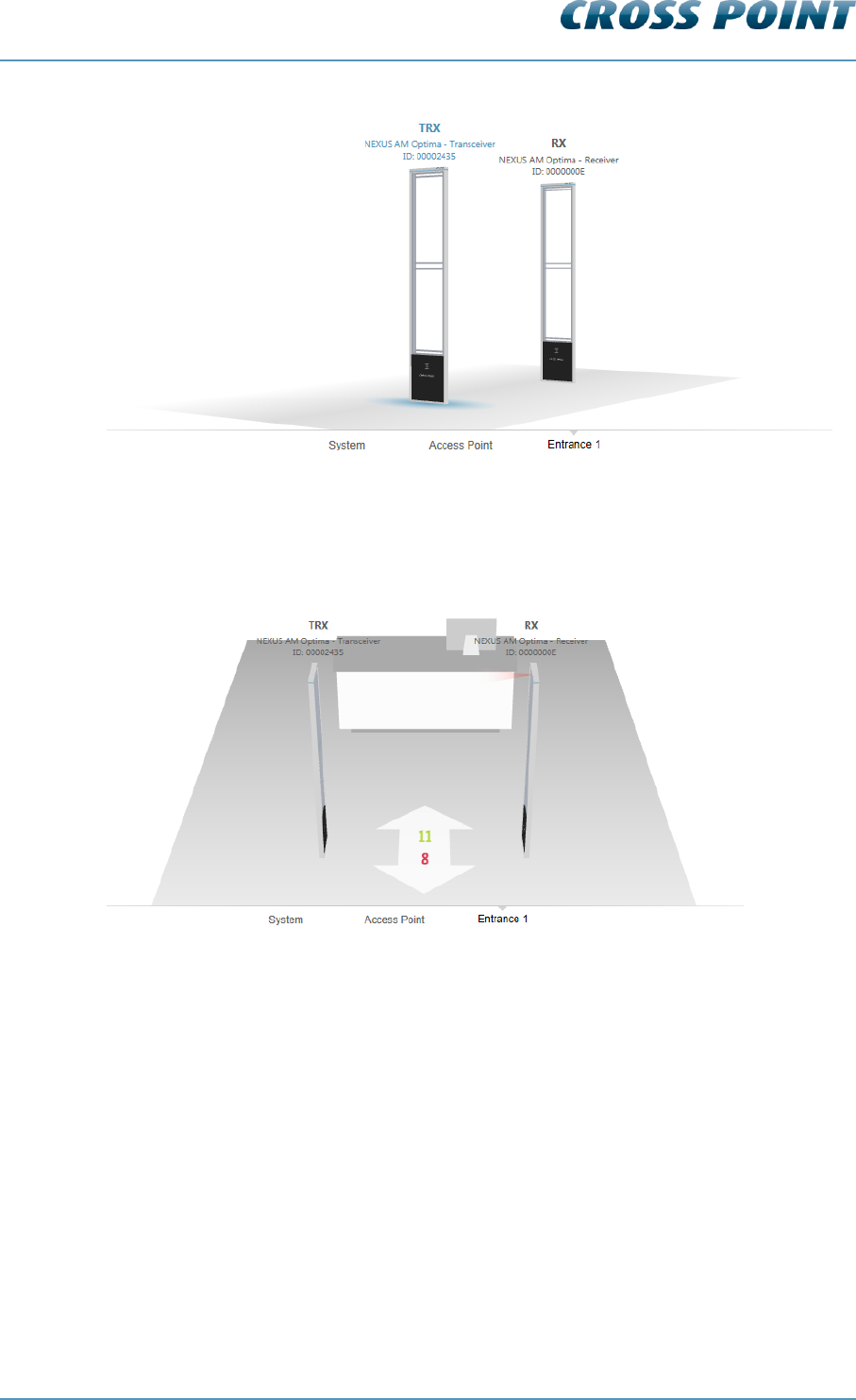
Perspective view 8.7.3.2
Click this button to change the 3D view into a perspective view, to be able to quickly
navigate to a specific aisle or antenna, especially useful for large installations.
Technical Manual AM Systems
Cross Point Device Explorer v4.4 Page 47 of 72
Figure 34: Perspective view
Counting view 8.7.3.3
Click this button to change the 3D view to helicopter view and see the number of visitors
or alarms per aisle.
Figure 35: Counting view - Visitors
The visitors counting view is only available for AM systems with integrated visitor
counters.
The green number indicates the number of visitors that have entered the store through
that aisle. The red number indicates the number of visitors that have left the store through
that aisle.
Technical Manual AM Systems
Cross Point Device Explorer v4.4 Page 48 of 72
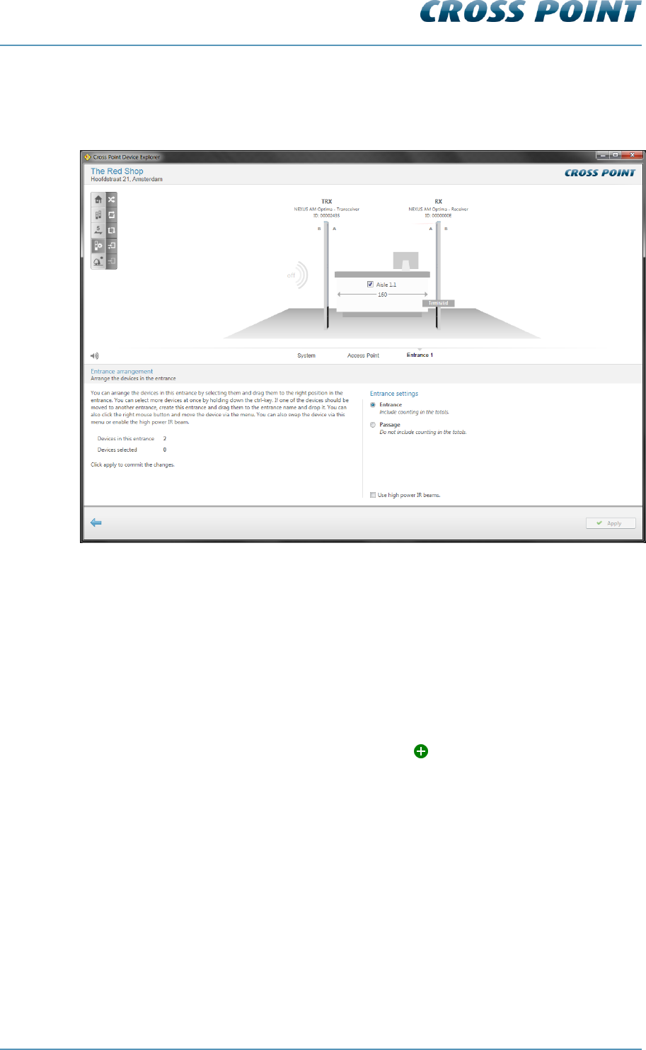
Entrance arrange view 8.7.3.4
Click this button if you want to make any changes to the antenna arrangement or other
entrance and antenna related properties.
Figure 36: Entrance arrangement mode
In the Main menu, an extra entrance named “Unarranged” appears. If any antennas could
not be automatically arranged or extra antennas are added after automatic antenna
arrangement was performed, these antennas are automatically added to the Unarranged
entrance.
You can now either start the automatic antenna arrangement by clicking the
Automatically arrange all antennas button in the button bar or drag & drop antennas
manually from the Unarranged entrance into the appropriate entrance.
Antennas can be picked up by clicking on the antenna image and moving the antenna
while keeping your left mouse button pressed. Move the antenna over the name of the
destination entrance and you will see the plus-sign appear. To place the antenna in
that entrance, just release the left louse button.
In the same way, antennas can also be swapped to another position within the same
entrance. Visitor counters will be enabled or disabled automatically dependent of the
position of the moved antenna in relation to the other antennas.
To select and move multiple antennas at once, keep the Ctrl button on your keyboard
pressed while selecting the required antennas. After selecting all antennas, release the
Ctrl key and drag & drop the antennas in the desired entrance.
In case antenna positions collide with the actual connection of the antennas (A- and B-
sides), a notification panel for each antenna will appear indicating the potential error.
Each antenna can be inverted by a right mouse click on the antenna and enabling or
disabling the option “A & B swapped”.
The names of the antennas, aisles and entrances can be changed by clicking on the
name and entering the new name. Just click somewhere outside of the text input field to
apply the new value.
Technical Manual AM Systems
Cross Point Device Explorer v4.4 Page 49 of 72
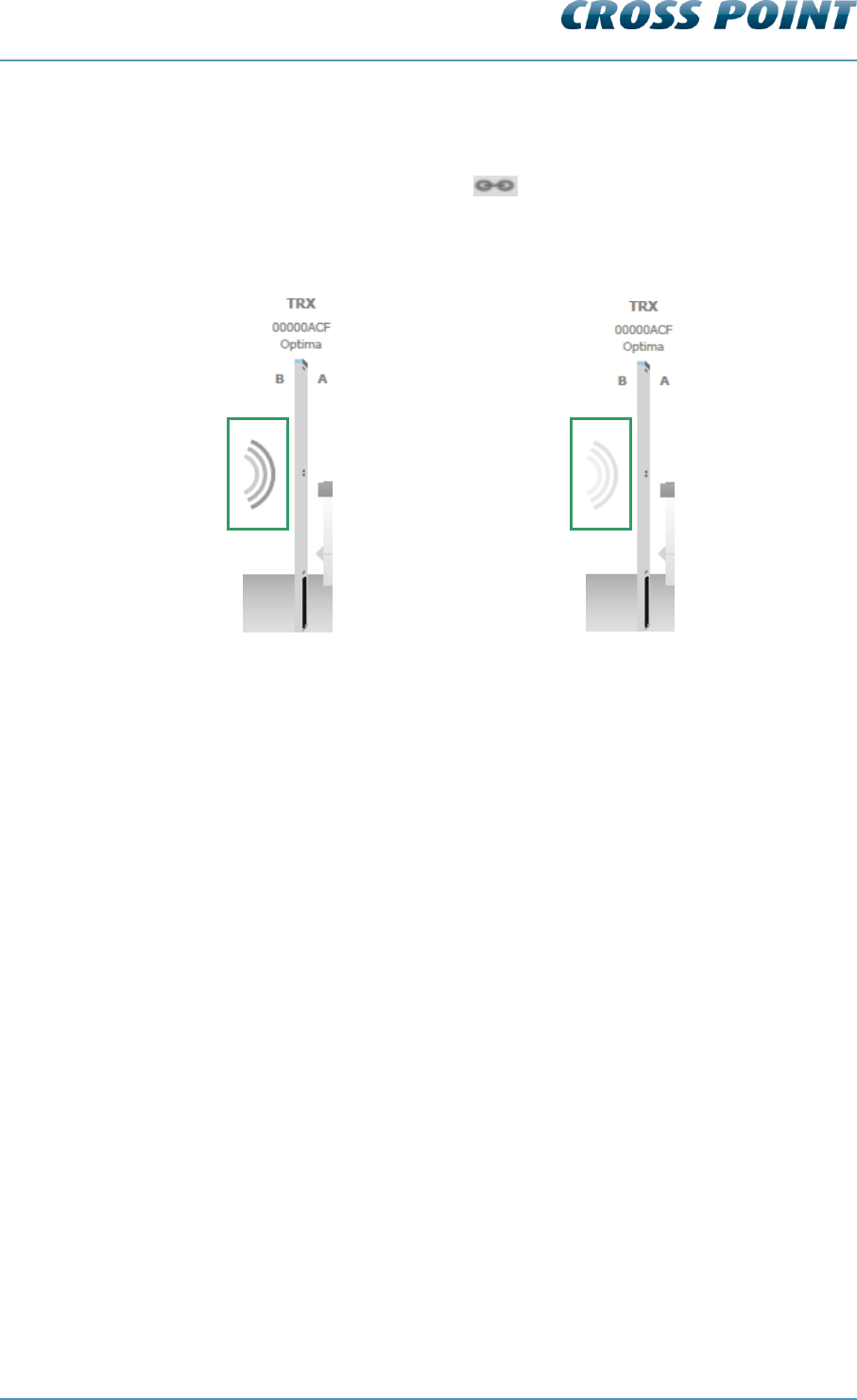
The aisle width for each aisle can be specified. By default the value is set to 160cm, but
can be changed to the actual value by clicking on the aisle width en entering the correct
value. In case all aisles in this entrance have the same aisle width, just enter the value for
one aisle and then click the chain button to change all aisles to the same aisle
width.
The backfield of a AM transceiver can be enabled or disabled by clicking on the waves at
the backside of the transceiver.
Figure 37: Enabling or disabling backfield detection
Entrance or passage? 8.7.3.4.1
When the entrance is set as an ‘entrance’, visitor counting numbers will be added to the
total number of visitors included in the visitor counting report. Select the option ‘Passage’
in case the visitor counting numbers of this specific entrance should not be added to the
total visitor counting.
Reverse view direction 8.7.3.5
By default the 3D-view shows the entrance from the outside looking into the store. This
view can be reversed (looking outside from within the store) by clicking the Reverse view
button. This does not change the actual counting direction!
Backfield enabled
Backfield disabled
Technical Manual AM Systems
Cross Point Device Explorer v4.4 Page 50 of 72
8.7.4 Entrances – selected entrance
When an entrance is selected in the Main menu and the Home button in the button bar is
pressed, the bottom part of the screen will show the following tabs:
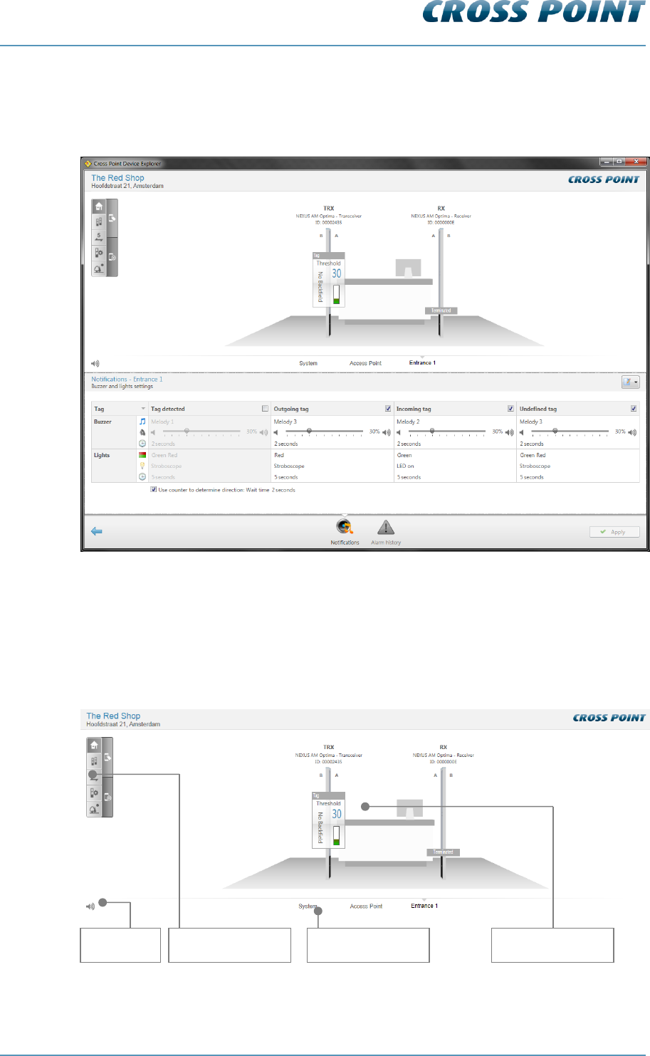
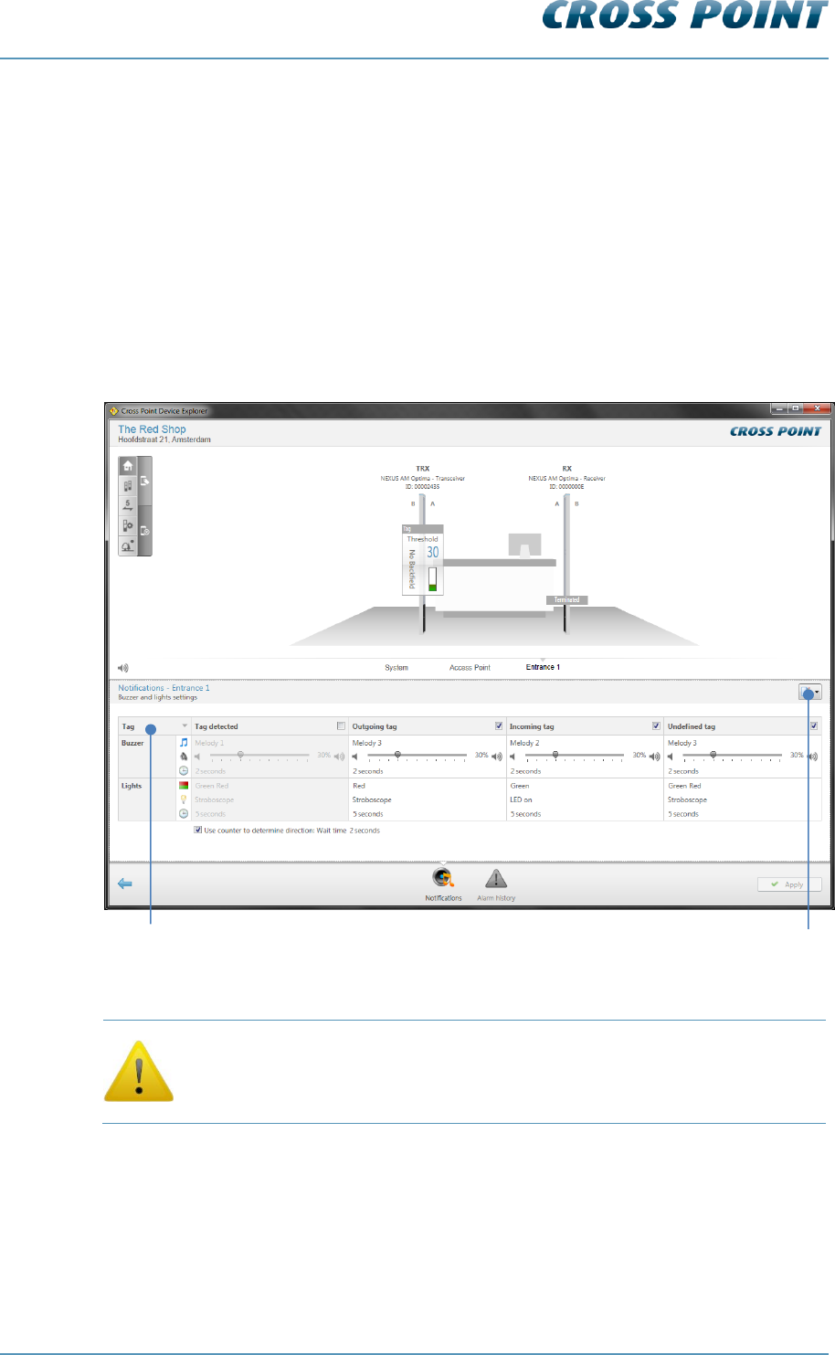
Notifications 8.7.4.1
In case of an alarm situation, notifications will be used to draw attention and to present
information about the type of alarm.
Notifications can be set for each entrance individually, when different notifications per
entrance are required, or you can set the notifications for all entrances at once. To do
this, go to System and specify the required notification settings. See section 8.8 for more
details.
Figure 38: Entrance notification settings
Entrance notification settings apply to all antennas that are part of the
selected entrance. It is not possible to create different individual
notification settings within the same entrance!
The following notification types can be selected by clicking on the cell in the top left
corner of the notifications table:
Alarms
Metal
Visitors
Other
Select notification type here
Pre-defined notifications
Technical Manual AM Systems
Cross Point Device Explorer v4.4 Page 51 of 72
Alarms 8.7.4.1.1
Notification
Explanation
Tag detected
This notification can be used as a ‘pre-alarm’ feature when the
option “Use visitor counter to distinguish in- and outgoing
alarms” has been enabled.
In case the option “Use visitor counter to distinguish in- and
outgoing alarms” is disabled (so no detection of incoming and
outgoing alarms), this notification must be used as the general
alarm setting.
Outgoing*
Notification setting for outgoing alarms*
Incoming*
Notification setting for incoming alarms*
Undefined/Ghost*
Notification setting for alarms where the direction could not be
determined*
Table 5: Alarm notifications
* depends on setting “Use counter to determine direction”
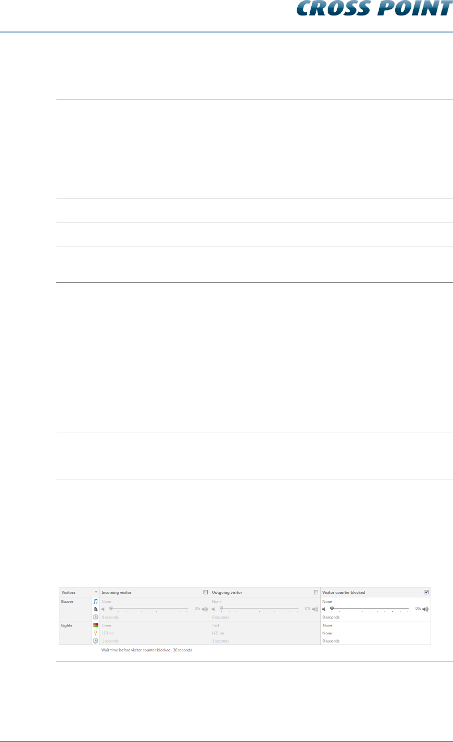
Visitors 8.7.4.1.2
Notification
Explanation
Incoming visitor
When a visitor enters the store, a ‘door bell’ notification can be
triggered to notify employees in the store that a visitor has just
entered the store.
Outgoing visitor
When a visitor leaves the store, a ‘door bell’ notification can be
triggered to notify employees in the store that a visitor just left
the store.
Visitor counter blocked
When the infra-red beam of the visitor counter is blocked for a
specific minimum amount of time (default 30 seconds), a
counter blocked notification can be triggered to notify visitors
and employees in the store that there is an aisle blockage.
NOTE: The wait time before visitor counter blocked can be
adjusted to another value if required. Just specify a value
between 1 and 3600 seconds.
Table 6: Visitor counter notifications
Technical Manual AM Systems
Cross Point Device Explorer v4.4 Page 52 of 72
Other notifications 8.7.4.1.3
Notification
Explanation
Default notification
Enable this notification if you want to visualize that the antenna
is switched on. For example the green LED can be switched on
infinite to show the visitor that the system is active.
Tamper alarm
When a tamper sensor is connected to the transceiver board, a
notification can be triggered when the cover of the antenna is
removed without authorization.
Detection disabled
Tag detection can be temporarily disabled (through one of the
available I/O’s). Set this notification to indicate when tag
detection has been disabled.
System jammed
Set this notification to notify store employees in case the
system is being jammed with a jamming device or as a result of
another high noise source.
Table 7: Other notifications
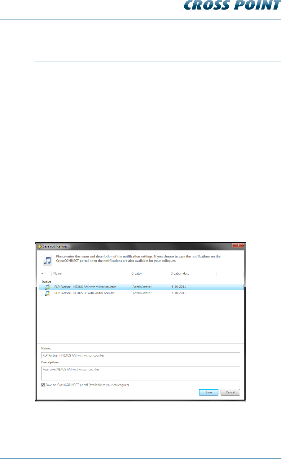
Saving notification settings 8.7.4.1.4
Notification settings can be saved for usage in other entrances or stores. Click the Load
and save notifications button and select the option ‘Save notifications’ from the menu
and the Save notifications dialog opens.
Figure 39: Save notifications
A list with pre-defined notifications that have previously been saved appears. Select one
from the list to overwrite the selected pre-defined notification, or enter a new name and
description for the new notification.
Technical Manual AM Systems
Cross Point Device Explorer v4.4 Page 53 of 72
If you have an active internet connection, you can also tick the checkbox in front of the
option ‘Save on server’ to store this new pre-defined notification centrally, so it is also
available for your colleagues.
Click the Save button to store the notification.
Select a notification and click the Delete button to delete a pre-defined notification.
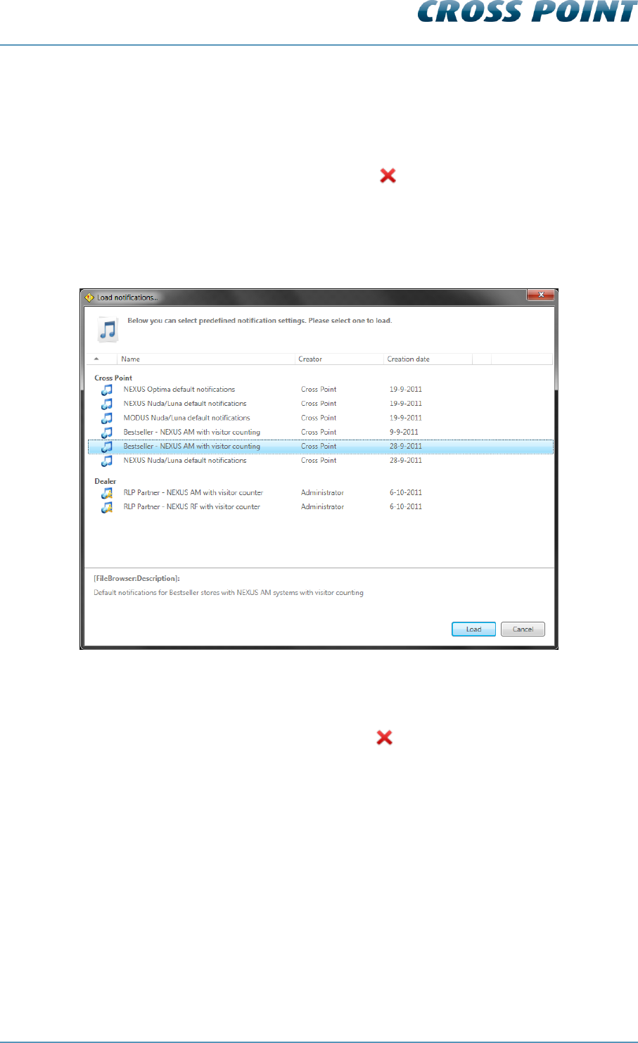
Loading pre-defined notifications 8.7.4.1.5
Pre-defined notification settings can be loaded again by clicking the Load and save
notifications button, selecting the option ‘Load notifications’ from the menu and the Load
notifications dialog opens.
Figure 40: Load notifications
A list with pre-defined notifications that have previously been saved appears. Select the
required notification and click the Load button to load the pre-defined notification settings.
Select a notification and click the Delete button to delete a pre-defined notification..

Technical Manual AM Systems
Cross Point Device Explorer v4.4 Page 54 of 72
Alarm history 8.7.4.2
The Alarm history screen shows a list of the tags that have been detected on all antennas
in this entrance.
Figure 41: Alarm history
Dependent of the notification settings, the incoming , outgoing and undefined
alarms can be distinguished by means of their individually colored icons.
By default all types of alarms are displayed, but pressing one or more of the filter buttons
will show or hide the selected alarms.
Click the Delete button to delete all alarms in the list and to permanently remove them
from all the connected antennas in this entrance.
All alarms are date & time stamped, so it’s easy to find out when they occurred.
For AM systems a maximum of 338 alarms can be stored in the memory of each AM TRX
board. When the memory is full, the oldest alarm will be replaced with the newest alarm
(FIFO principle). It is possible to view the alarm history per day for a maximum of the last
30 days or less, in case the maximum number of alarms has been reached within 30
days.
Just click the Previous/Next day buttons to scroll through the alarm history.
Technical Manual AM Systems
Cross Point Device Explorer v4.4 Page 55 of 72
8.7.5 Entrances – selected antenna
If you click on a TRX or RX antenna in the 3D-view, some individual antenna settings can
be configured.
Transceiver (TRX) settings 8.7.5.1
When a TRX antenna is selected in the 3D-view, the following tabs will appear at the
bottom of the screen:
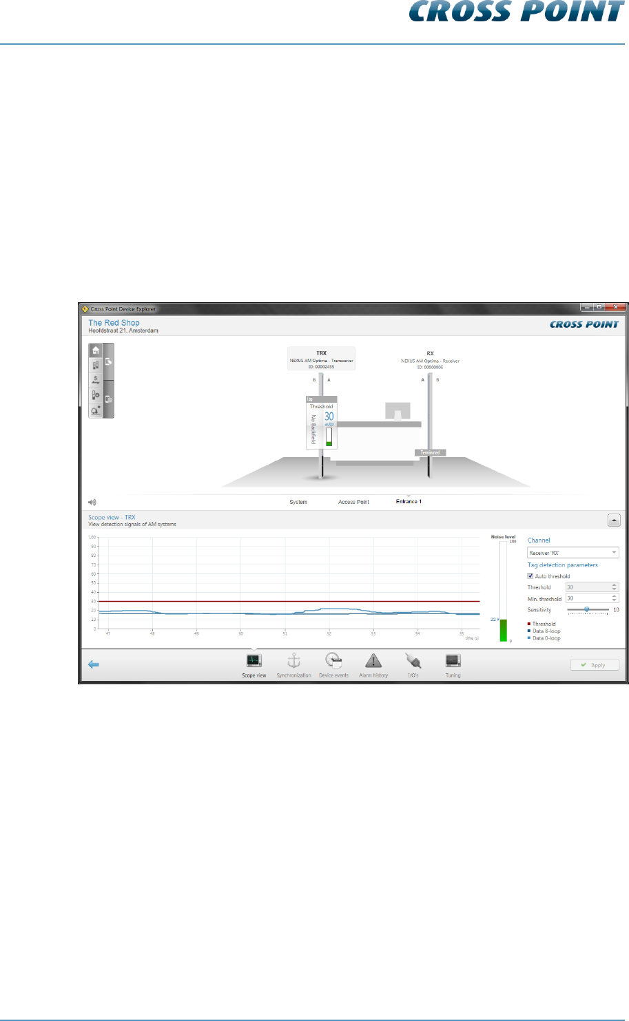
Scope view 8.7.5.1.1
The Scope view screen shows the signal that is received by the receiver part of the
transceiver and/or separate receiver(s) that might be connected to the transceiver.
Figure 42: Scope view
Dependent of the number of connected receivers and whether the backfield of the
transceiver is on or off, the Channel dropdown box lets you select the device that you
want to work on
The Scope view itself shows the signals that are being detected on the antenna’s 0-loop
and 8-loop configuration (blue lines).
The red line is the threshold level. The threshold level actually determines the sensitivity
of the transceiver/receiver. A low threshold level creates a high sensitivity, where a high
threshold level results in low sensitivity.
When a signal (blue line) rises above the threshold level (red line), the alarm will be
triggered.

Technical Manual AM Systems
Cross Point Device Explorer v4.4 Page 56 of 72
The threshold level can be adjusted in two ways; automatically or manually
Automatic threshold level adjustment
Tick the Automatic threshold checkbox to activate automatic threshold level adjustment.
Depending on the environmental noise levels, the transceiver will automatically and
continuously adjust its threshold level higher than the noise levels.
The Minimum threshold option will prevent the threshold level from getting too low,
potentially making the system too sensitive.
Manual threshold level adjustment
Un-tick the Automatic threshold checkbox to activate manual threshold level adjustment.
By entering a value manually or by pushing the up or down arrows, the required threshold
level can be set. Alternatively, the slider next to the scope view can be moved up or down
to set the required level.
Sensitivity
The sensitivity slider can be used to decrease or increase the total sensitivity of the
antenna. The default value is 10 and you can increase the sensitivity to 20, or decrease it
to 1.
Noise
The noise level indicator shows a value between zero and one hundred, which represents
the amount of noise that’s being detected by this receiver. A high noise level will result in
reduced detection, which means that specified detection distances might not be
achieved. To improve this situation the noise source(s) must be located and removed. If
removal of the noise source is not possible, the aisle width between the antennas needs
to be reduced, which means that the transceiver and receiver antennas need to be
installed closer to each other.
Never adjust the antenna too sensitive, as this will result in false alarms!
Remove the noise sources that interfere with the system or move the
antennas as far as possible away from noise sources.
Synchronization AM 8.7.5.2
When multiple AM systems are installed in relative close vicinity of each other, it is of
extreme high importance that the transmission bursts of all transmitters (transceivers)
occur at the same moment. To be able to view and change the position of these
transmission bursts, the Synchronization screen is available.
When the Synchronization screen is open, the transmission burst of this
transceiver is disabled. As a result of this, the transceiver and
connected receiver(s) will not detect any tags! Make sure to leave this
screen to enable detection of tags again.
When the transmission bursts are not synchronized properly, false alarms and reduced
sensitivity will be the result. The Synchronization screen will show exactly if and where
other system transmission bursts are detected.
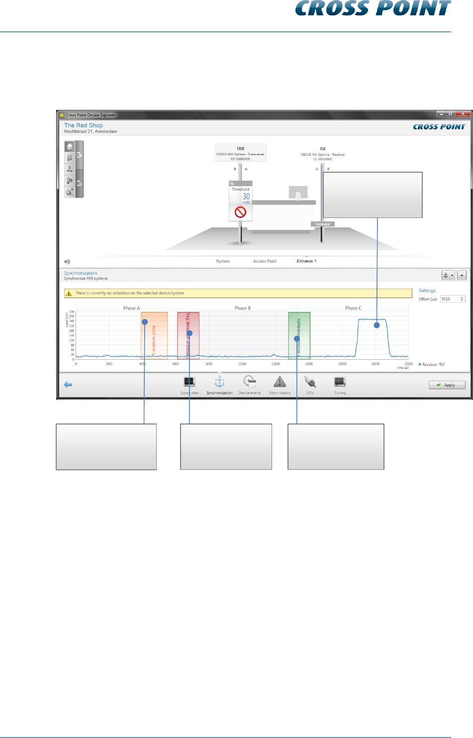
Technical Manual AM Systems
Cross Point Device Explorer v4.4 Page 57 of 72
Figure 43 shows an example of faulty synchronization. Our system’s transmission burst
(Burst window 1, indicated as a vertical orange bar) is at a different moment in time than
the other system’s transmission burst, which is on its turn causing interference in our
system’s detection window.
Figure 43: AM synchronization – wrong adjustment
Our system’s
transmission burst
window (orange bar)
Our system’s
detection window
(red bar)
Our system’s
rereference window
(green bar)
Other system’s
transmission bursts
(blue curve)
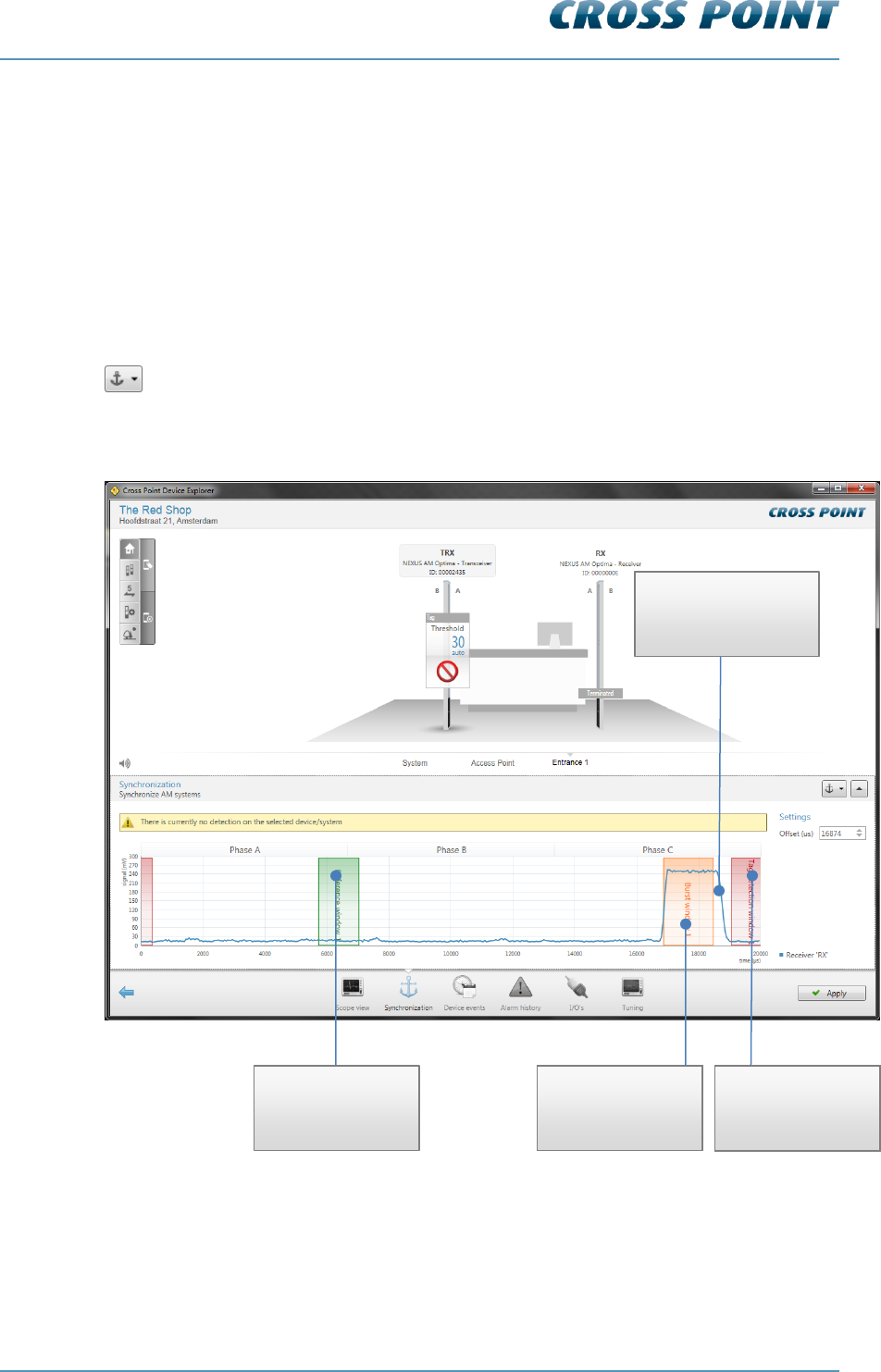
Technical Manual AM Systems
Cross Point Device Explorer v4.4 Page 58 of 72
We now have two ways of synchronizing the systems; manually or automatically.
Manual synchronization
By default the transmission burst can be synchronized manually by dragging and moving
the burst throughout the complete 20ms time base.
Just hover the mouse cursor over our transmission burst (the cursor will change to a
horizontal double arrow) and press down your left mouse button. While keeping the
mouse button pressed, move the transmission burst and position it on top of the other
system’s transmission burst. Together with moving the transmission burst, also the
receiver and reference windows will move automatically since they have a fixed reference
to the transmission burst.
Automatic synchronization
It is also possible to let the software detect the best position for the transmission burst.
Just click the Automatic Sync button and within 10 to 15 seconds the software will have
determined the best burst offset position.
Figure 44: Synchronization AM – correct adjustment
Figure 44 shows our system being properly synchronized with the other system’s
transmission burst. Our transmission burst is on top of the other system’s transmission
burst and both our receiver and reference windows are not on top of any other
transmission bursts.
Our system’s
receiver window
(red bar)
Our system’s
transmission burst
(orange bar)
Our system’s
reference window
(green bar)
Other system’s
transmission bursts
(blue curve)

Technical Manual AM Systems
Cross Point Device Explorer v4.4 Page 59 of 72
Temporarily disabling other device bursts 8.7.5.2.1
When you start synchronizing entrance(s), start by selecting the Synchronization page of
the first device. It is very useful to switch the transmission bursts of all other entrances
off, so you can determine if there are any other AM systems in the area, to which you
must synchronize your system.
To switch the transmission bursts of the other devices off, select the Automatic
synchronization button to unfold a list of all other available devices.
Click on the green checkmark in front of the device name to disable the transmission
burst of that device. The disabled icon will appear, indicating the transmission burst for
that device is switched off. Click this icon again to switch the burst on again.
When you leave the Synchronization page, all disabled devices will automatically start
bursting again.
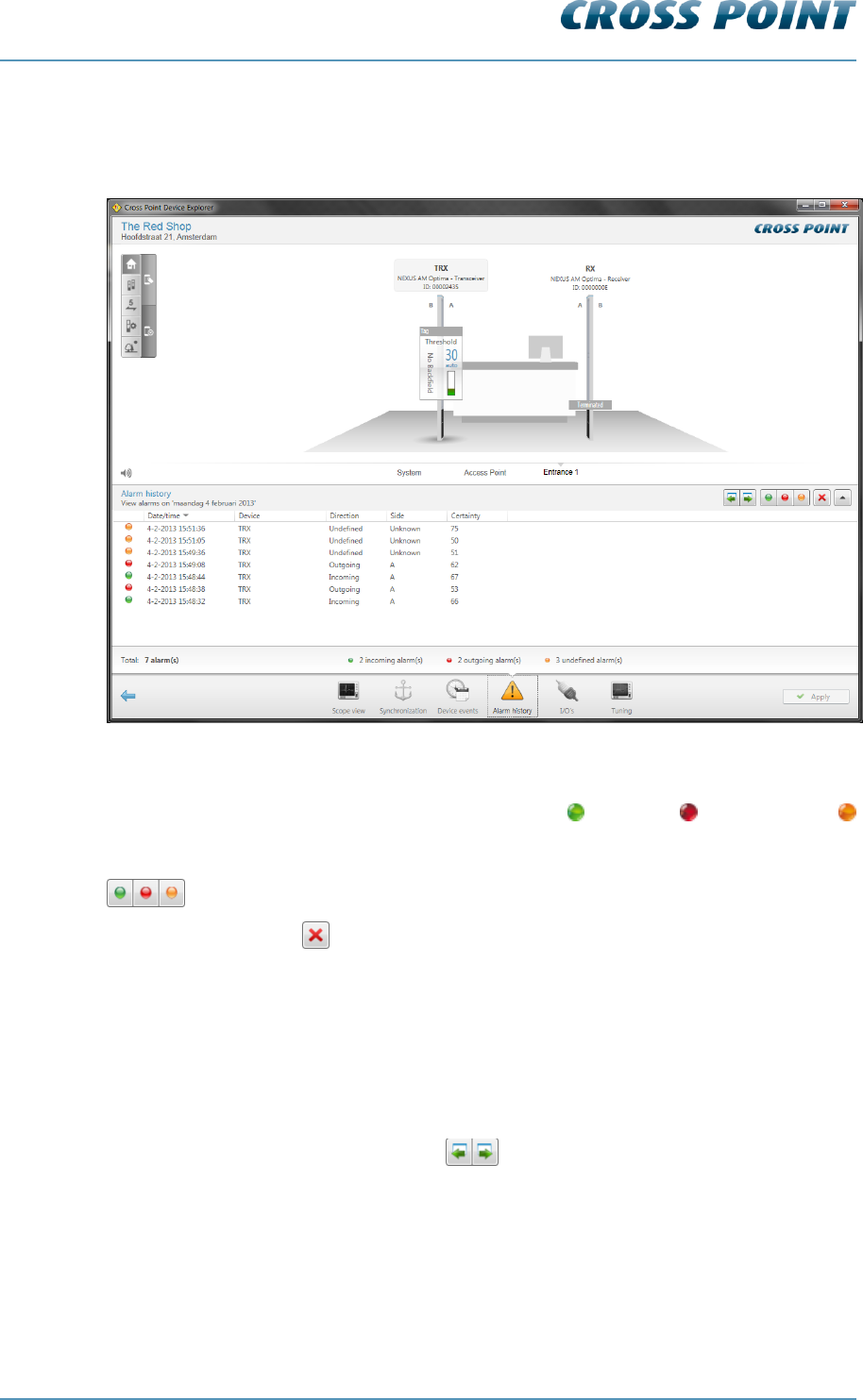
Technical Manual AM Systems
Cross Point Device Explorer v4.4 Page 60 of 72
Alarm history 8.7.5.2.2
The Alarm history screen shows a list of the tags that have been detected on the selected
antenna.
Figure 45: Alarm history
Dependent of the notification settings, the incoming , outgoing and undefined
alarms can be distinguished by means of their individually colored icons.
By default all types of alarms are displayed, but pressing one or more of the filter buttons
will show or hide the selected alarms.
Click the Delete button to delete all alarms in the list and to permanently remove them
from all the connected antennas in this entrance.
All alarms are date & time stamped, so it’s easy to find out when they occurred.
For AM systems a maximum of 338 alarms can be stored in the memory of each AM TRX
board. When the memory is full, the oldest alarm will be replaced with the newest alarm
(FIFO principle). It is possible to view the alarm history per day for a maximum of the last
30 days or less, in case the maximum number of alarms has been reached within 30
days.
Just click the Previous/Next day buttons to scroll through the alarm history.
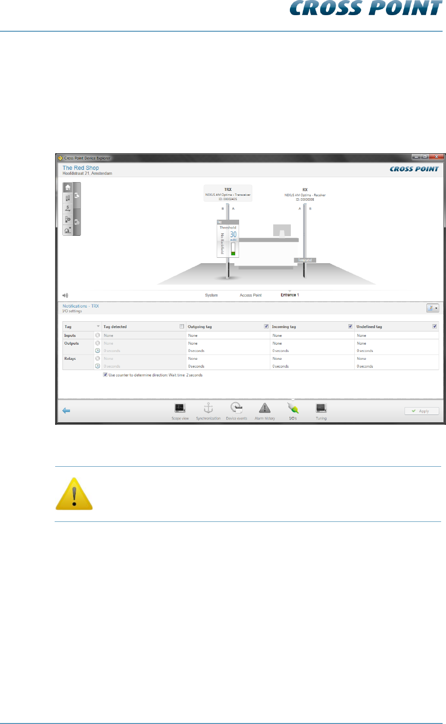
Technical Manual AM Systems
Cross Point Device Explorer v4.4 Page 61 of 72
Notifications – I/O settings 8.7.5.2.3
Next to the audio and visual alarm notifications, as described in section 8.7.4.1, also a
relay and a maximum of 2 I/O’s can be programmed to activate any external device
(camera, external buzzer, etc.) during an alarm situation.
These notification settings have to be programmed on each individual antenna, since the
relay and I/O’s are antenna specific. Any externally connected device needs to be
physically connected to the antenna.
Figure 46: Notifications – I/O settings
Relay and I/O notification settings apply only to an individual antenna!
The following notification types can be selected by clicking on the cell in the top left
corner of the notifications table:
Alarms
Metal
Visitors
Other
Refer to section 8.7.4.1 to view all available notification types.
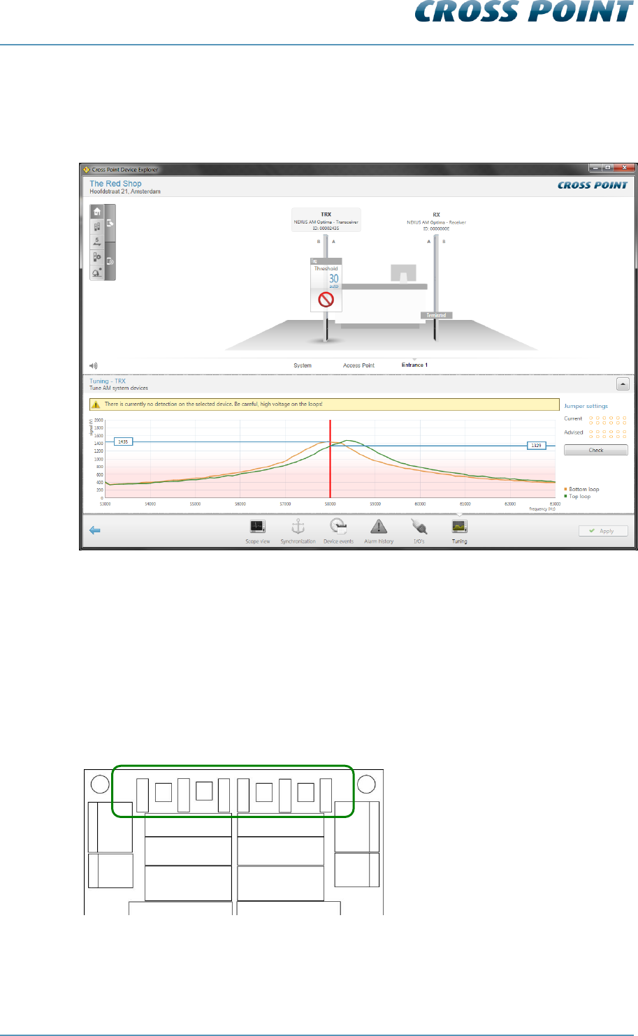
Technical Manual AM Systems
Cross Point Device Explorer v4.4 Page 62 of 72
Tuning AM 8.7.5.2.4
The AM transceiver is performing at its best when maximum power is being transmitted at
58kHz. The Tuning screen shows a graphical display of the top and bottom antenna loop
tuning and their associated power.
Figure 47: Tuning AM
By changing the positions of the antenna jumpers on the transceiver board, you can find
the positions for both loops where they have the highest voltage output at 58kHz (the
vertical red line). The spot where the curves cross the red line is the actual transmitted
power. A higher output will increase the performance of the AM system, where a lower
output will result in less performance.
Make combinations of transceiver jumpers TUNE TOP1, TUNE TOP2, TUNE TOP3 to
achieve the highest voltage for the top antenna loop and do the same for the bottom
antenna loop using jumpers TUNE BOT1, TUNE BOT2 and TUNE BOT3.
Figure 48: Transceiver board antenna tuning jumpers
ANT
BOT2
ANT
BOT1
ANT
TOP2
ANT
TOP1
TUNE TOP1
TUNE TOP2
TUNE TOP3
TUNE BOT3
TUNE BOT2
TUNE BOT1
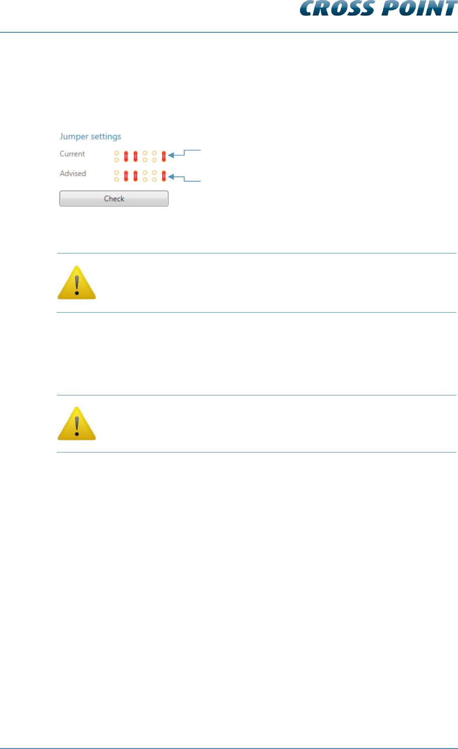
Technical Manual AM Systems
Cross Point Device Explorer v4.4 Page 63 of 72
Antenna tuning assistant
It can also be useful to use the Jumper settings assistant to determine the best jumper
positions. Just click the positions of the jumpers in the Current image to indicate the
current position of the jumpers on the board. Then click the Check button and the
Advised image will show the advised jumper settings for optimal performance.
Figure 49: Tuning assistant example
Be aware of the high antenna voltages! Switch the power supply to the
transceiver board off before tuning. Do not touch the backside of the
transceiver board or the metal tuning jumper pins when the board is
powered, as this might result in you receiving an electrical shock!
Tolerances in the components of the transceiver board make it possible that the actual
antenna jumper settings are different for each transceiver board and therefore the above
image might differ for each transceiver board.
When the Tuning screen is open, detection of tags is disabled. Make
sure to switch to another screen if you want to test the detection
performance!
1) Click on the jumpers to indicate your current setting
2) Press the Check button
3) The advised jumper setting will be shown
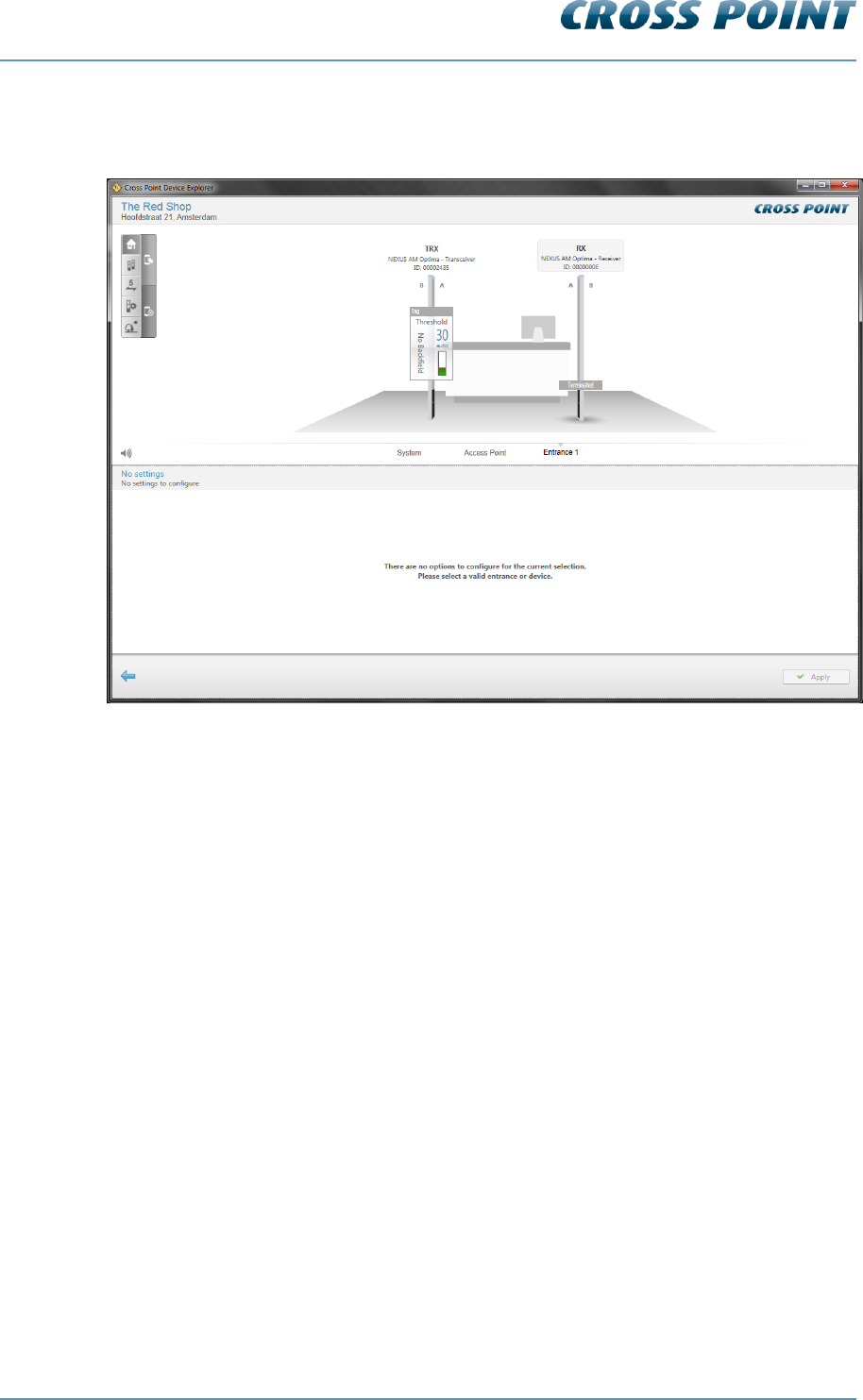
Technical Manual AM Systems
Cross Point Device Explorer v4.4 Page 64 of 72
Receiver (RX) settings 8.7.5.3
When an RX antenna is selected in the 3D-view, the following message appears:
Figure 50: Receiver selection
The message indicates that there are no options to configure for the selected device.
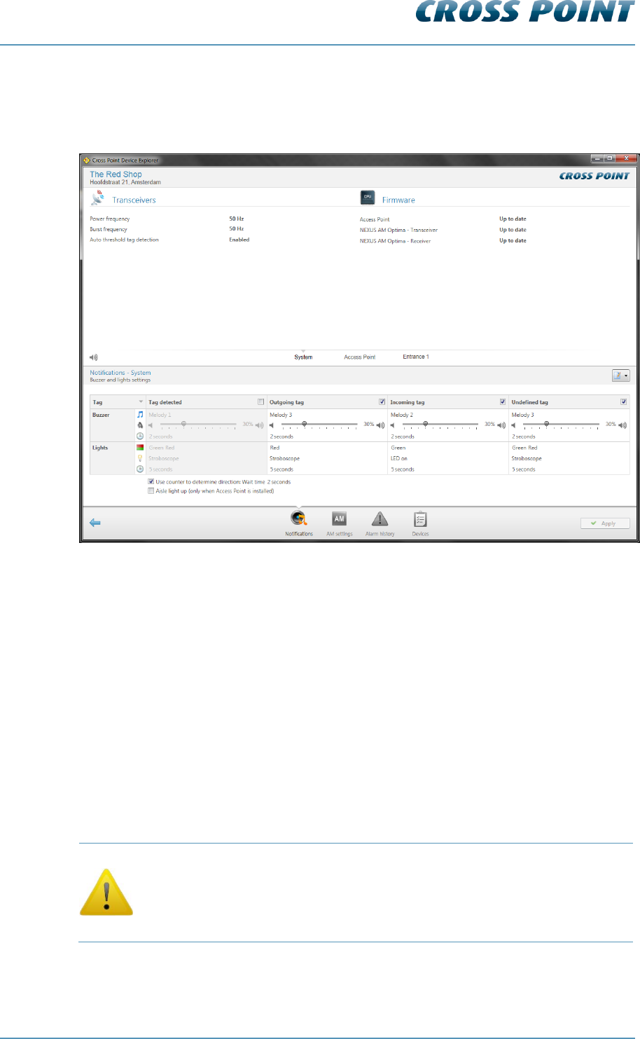
Technical Manual AM Systems
Cross Point Device Explorer v4.4 Page 65 of 72
8.8 System
Clicking the System hyperlink in the Main menu or clicking the System information
section in the dashboard will open the System information screen.
Figure 51: System information & notifications
The top-part of this screen shows information about the connected transceiver(s) and
whether the firmware of all connected devices is up-to-date. The bottom part shows 3
tabs:
8.8.1 Notifications
In case of an alarm situation, notifications will be used to draw attention and to present
information about the type of alarm.
Notifications can be set for all entrances at once by configuring the notifications in this
System screen. In case different notifications per entrance are required, select the
entrance and specify the required notification settings at entrance level. See section 8.7.4
for more details.
Notification settings, which are configured in this System screen, will be
applied system-wide, which means to all devices connected to this
Access Point. Any notification settings that have been configured for a
specific entrance will be overwritten with the values that are specified in
this System screen!
Refer to section 8.7.4.1 for more details on the available notification settings.
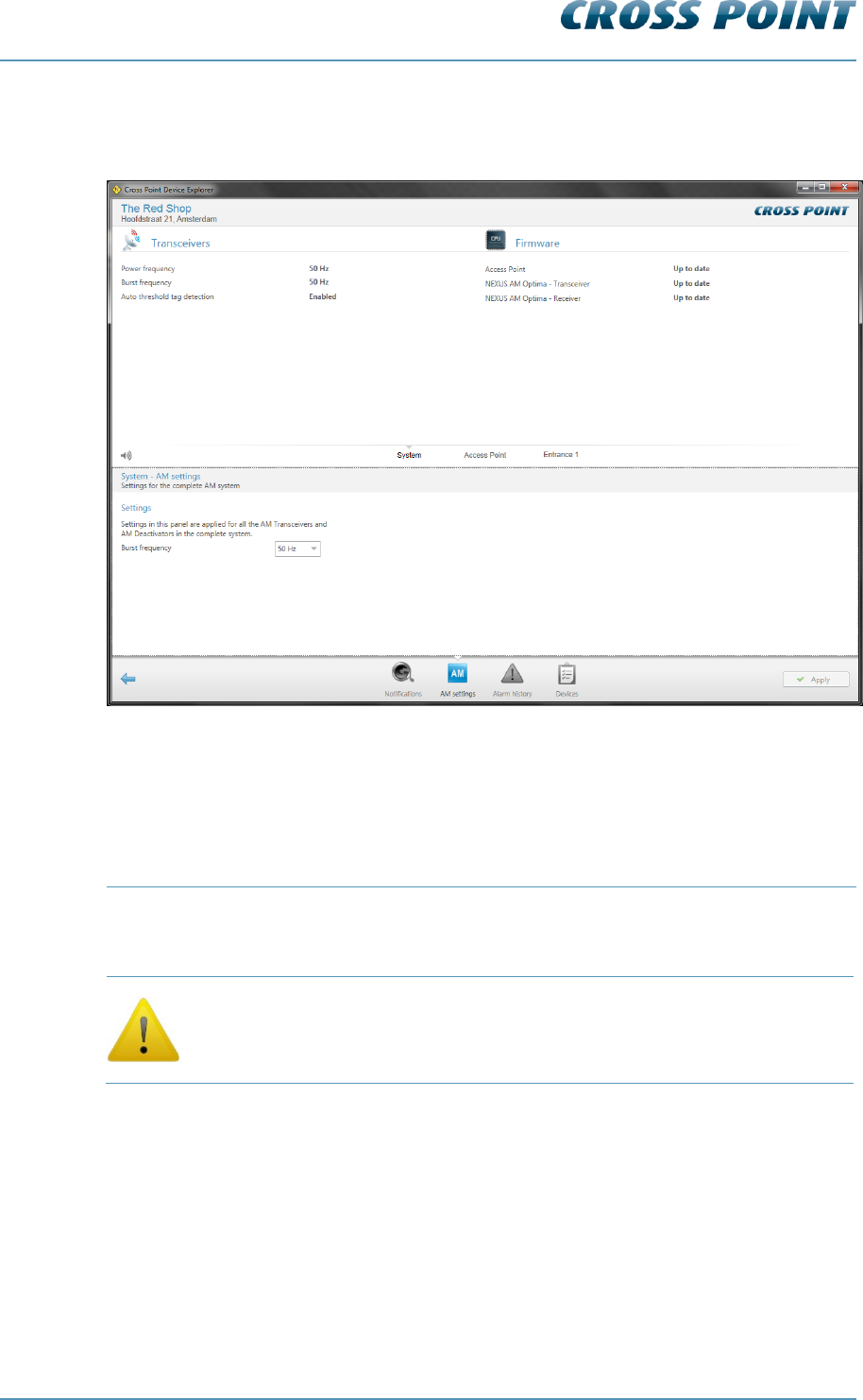
Technical Manual AM Systems
Cross Point Device Explorer v4.4 Page 66 of 72
8.8.2 AM settings
The AM settings screen allows specific AM settings to be changed.
Figure 52: AM settings
The Burst frequency setting defines how many times per second a transmission burst is
send. The available options are:
@50Hz power frequency
@60Hz power frequency
37.5Hz, 50Hz (default), 75Hz and 150Hz
45Hz, 60Hz (default), 90Hz and 180Hz
The burst frequency setting is a system wide setting, which will be
applied for all connected AM devices. It is not possible to set different
burst frequencies for different entrances.
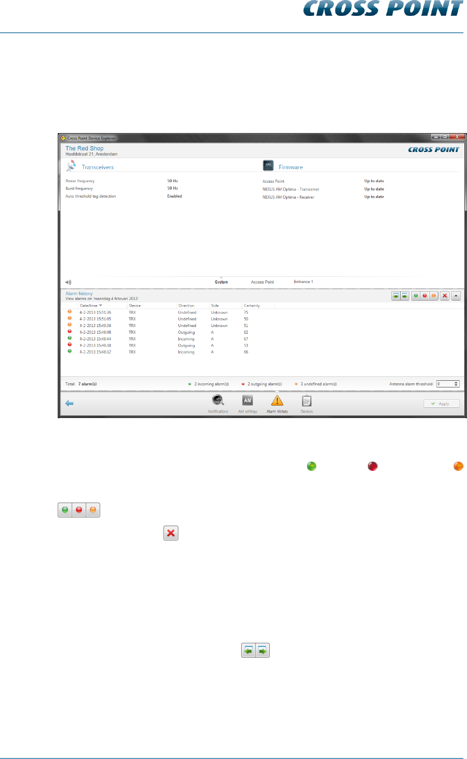
Technical Manual AM Systems
Cross Point Device Explorer v4.4 Page 67 of 72
8.8.3 Alarm history
The system’s Alarm history screen shows a list of the tags that have been detected on
the entire system (all antennas in all entrances). The information is retrieved from the
antennas when you enter this screen, so it may take some time before the information is
visible.
Figure 53: System – Alarm history
Dependent of the notification settings, the incoming , outgoing and undefined
alarms can be distinguished by means of their individually colored icons.
By default all types of alarms are displayed, but pressing one or more of the filter buttons
will show or hide the selected alarms.
Click the Delete button to delete all alarms in the list and to permanently remove them
from all the connected antennas in this entrance.
All alarms are date & time stamped, so it’s easy to find out when they occurred.
For AM systems a maximum of 338 alarms can be stored in the memory of each AM TRX
board. When the memory is full, the oldest alarm will be replaced with the newest alarm
(FIFO principle). It is possible to view the alarm history per day for a maximum of the last
30 days or less, in case the maximum number of alarms has been reached within 30
days.
Just click the Previous/Next day buttons to scroll through the alarm history.
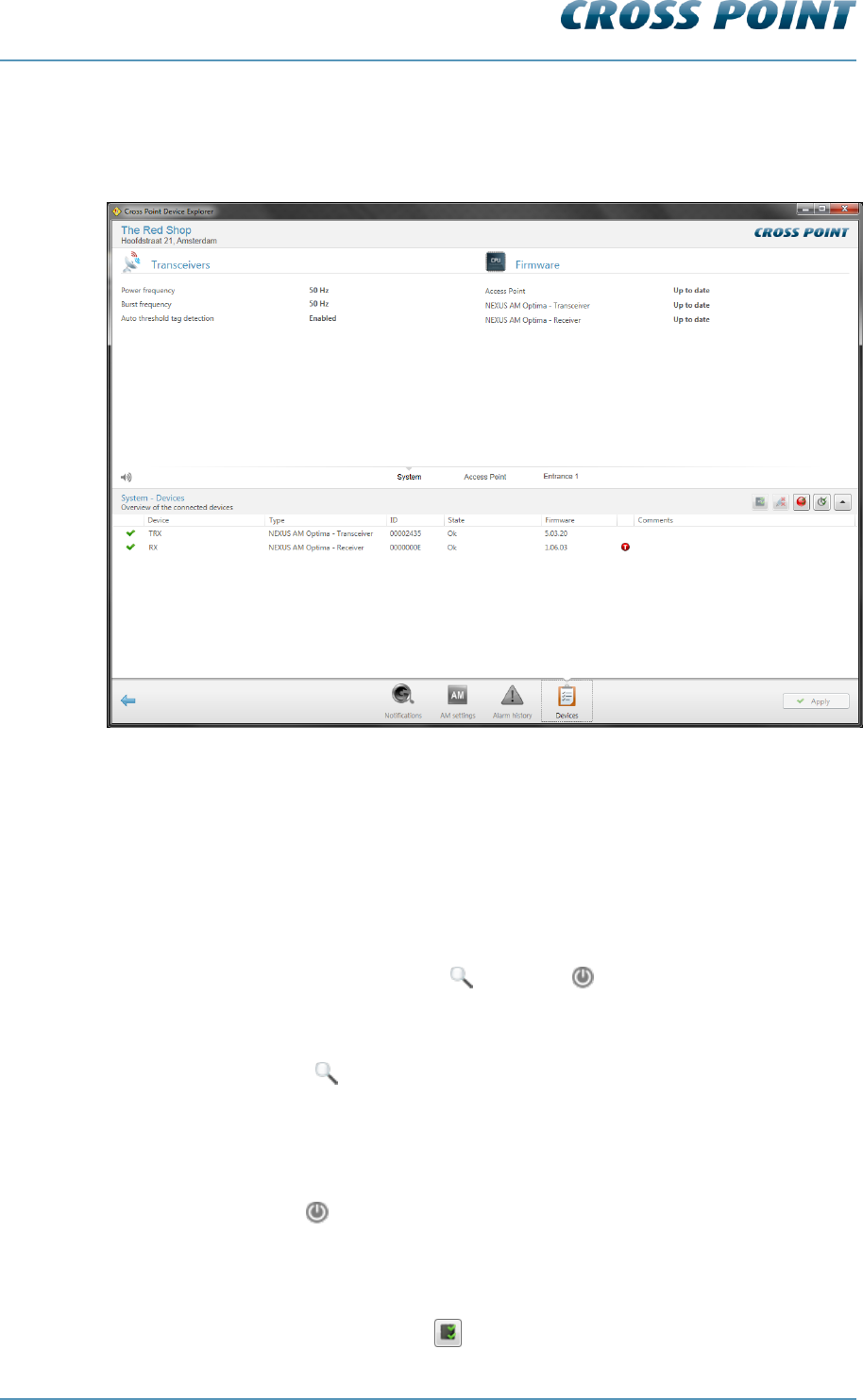
Technical Manual AM Systems
Cross Point Device Explorer v4.4 Page 68 of 72
8.8.4 Devices
The Devices screen shows a list of all connected devices, their firmware status and some
system settings.
Figure 54: System – Devices
In the Devices list it is possible to:
View the firmware version of each connected device
Upload new device firmware
Locate an individual device or all devices at once
Reset an individual device or all devices at once
Remove disconnected device(s)
Just hover over a device and the Locate and Reset buttons will appear.
Locating a device 8.8.4.1
Press the Locate button once to activate the buzzer and LEDs on the selected device.
The Locate icon will start blinking and will keep on blinking. Press the Locate button again
to stop locating the selected device.
Resetting a device 8.8.4.2
Press the Reset button to reset only the selected device.
Uploading new firmware 8.8.4.3
In case new firmware is available, you can automatically upgrade all devices of the same
type by pressing the Update all button .

Technical Manual AM Systems
Cross Point Device Explorer v4.4 Page 69 of 72
Removing disconnected devices 8.8.4.4
All devices that have the disconnected status can be removed permanently by pressing
the Remove disconnected devices button .
Turning all LEDs on/off 8.8.4.5
The LEDs on all connected devices can be switched on at once by pressing the Turn all
LEDs on button . This is useful to check whether all devices are connected, especially
in large installation. Press this button again to switch all LEDs off again.
Resetting all connected devices 8.8.4.6
Press the Reset all button to reset all connected devices at once.
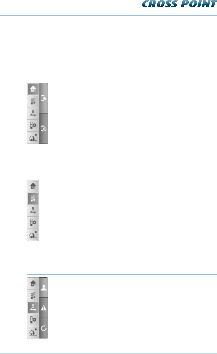
Technical Manual AM Systems
Cross Point Device Explorer v4.4 Page 70 of 72
8.9 Device Explorer Button Bar
This section covers the functionality of the button bar. Dependent of the selected button
bar button, a set of sub-buttons can appear.
8.10 Home view
Bar
Sub button function
Show tag panel
Hide panel(s)
8.11 Perspective view
Bar
Sub button function
<no sub buttons>
8.12 Counting view
Bar
Sub button function
Show visitor counting
Show alarm counting
Reset visitor or alarm counting totals
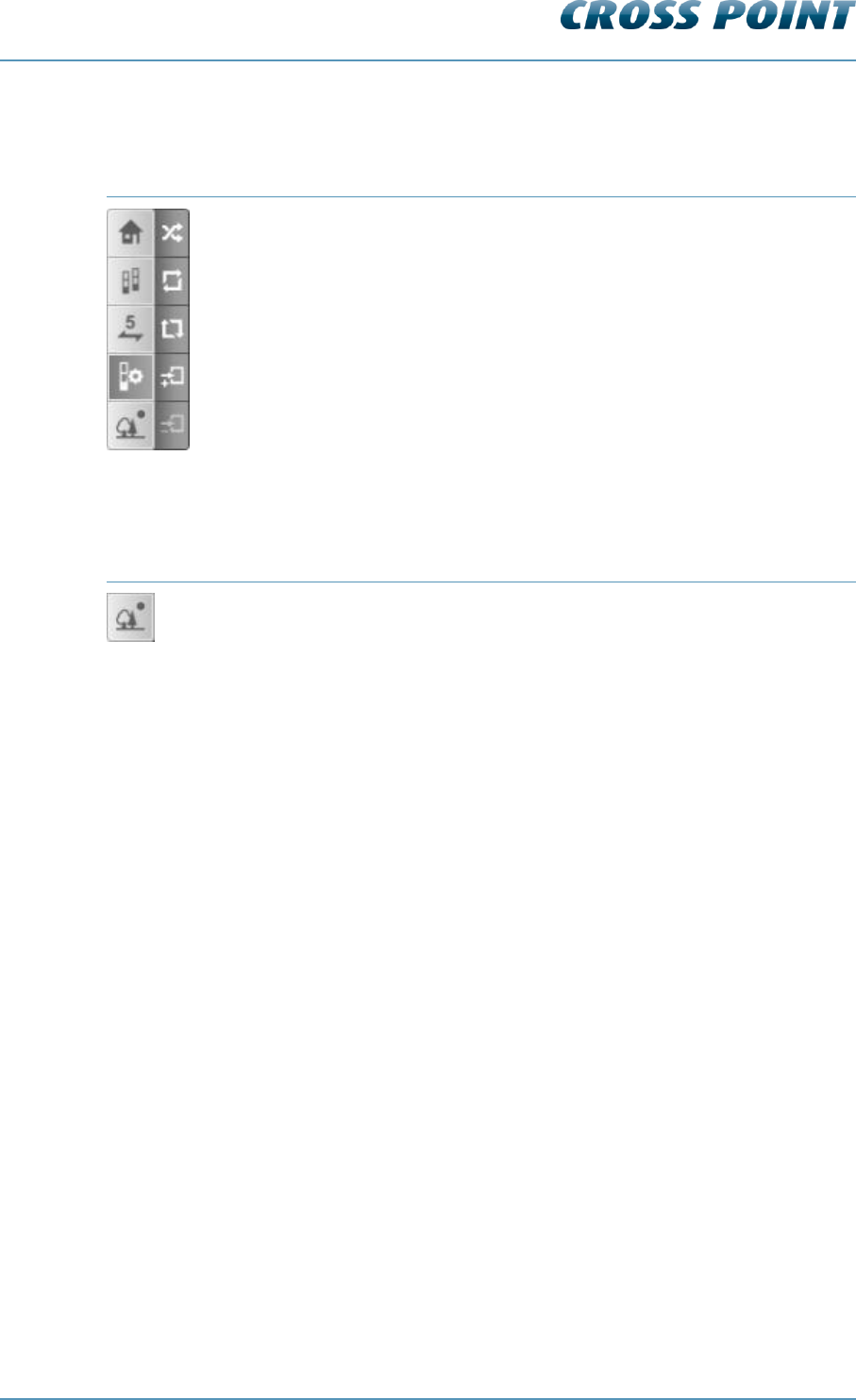
Technical Manual AM Systems
Cross Point Device Explorer v4.4 Page 71 of 72
8.13 Entrance view
Bar
Sub button function
Start automatic antenna arrangement
Mirror the devices in this entrance
Reverse visitor counting direction for all devices in this entrance
Add a new entrance
Remove an empty entrance
8.14 Toggle view direction
Bar
Button function
Toggle view direction (looking into the store or looking out of the store)

Technical Manual AM Systems
Regulatory information v4.4 Page 72 of 72
9 Regulatory information
FCC WARNING
This device complies with Part 15 of the FCC Rules. Operation is subject to the following
two conditions: (1) This device may not cause harmful interference, and (2) this device
must accept any interference received, including interference that may cause undesired
operation.
NOTE 1: This equipment has been tested and found to comply with the limits for a Class
B digital device, pursuant to part 15 of the FCC Rules. These limits are designed to
provide reasonable protection against harmful interference in a residential installation.
This equipment generates uses and can radiate radio frequency energy and, if not
installed in accordance with the instructions, may cause harmful interference to radio
communications. However, there is no guarantee that interference will not occur in a
particular installation. If this equipment does cause harmful interference to radio or
television reception, which can be determined by turning the equipment off and on, the
user is encouraged to try to correct the interference by one or more of the following
measures:
- Reorient or relocate the receiving antenna.
- Increase the separation between the equipment and receiver.
- Connect the equipment into an outlet on a circuit different from that to which the
receiver is connected.
- Consult the dealer or an experienced radio/TV technician for help.
NOTE 2: Any changes or modifications to this unit not expressly approved by the party
responsible for compliance could void the user’s authority to operate the equipment.
IC WARNING
This device complies with Industry Canada’s license-exempt RSSs. Operation is subject
to the following two conditions:
(1) This device may not cause interference; and
(2) This device must accept any interference, including interference that may cause
undesired operation of the device.
Le présent appareil est conforme aux CNR d’Industrie Canada applicables aux appareils
radio exempts de license. L’exploitation est autorisée aux deux conditions suivantes: (1)
l’appareil ne doit pas produire de brouillage, et (2) l’utilisateur de l’appareil doit accepter
tout brouillage readioélectrique subi, même si brouillage est susceptible d’en
compromettre le fonctionnement.