Cross Point CP301MAXRXA Electronic Article Surveillance(EAS) Pedestal User Manual title
Cross Point b.v. Electronic Article Surveillance(EAS) Pedestal title
UserManual.wiki
>
Cross Point
>
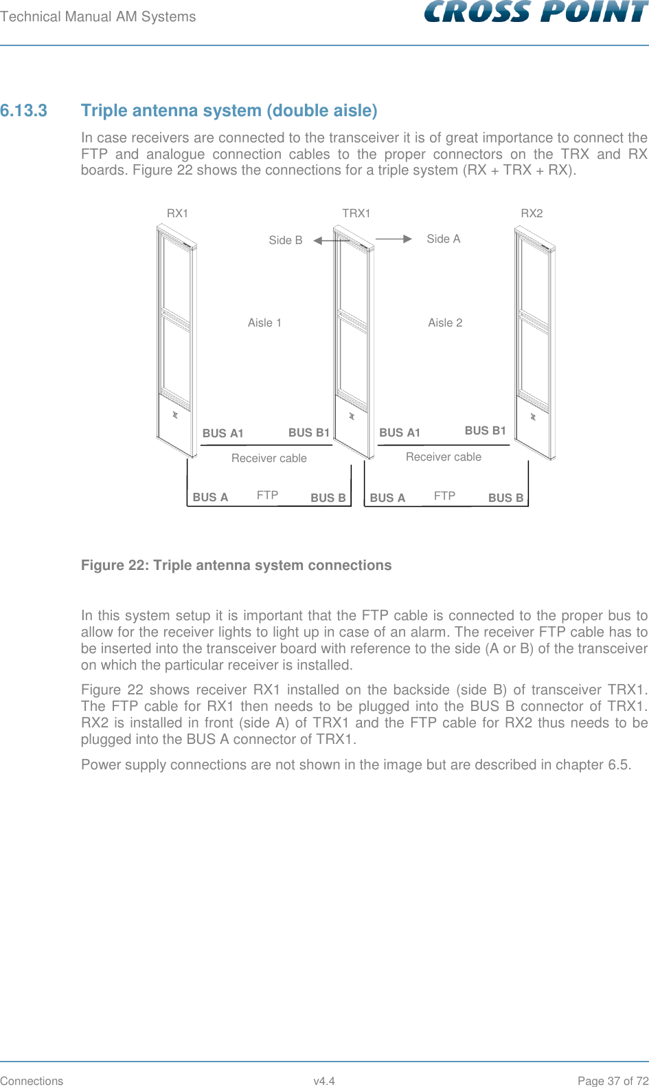
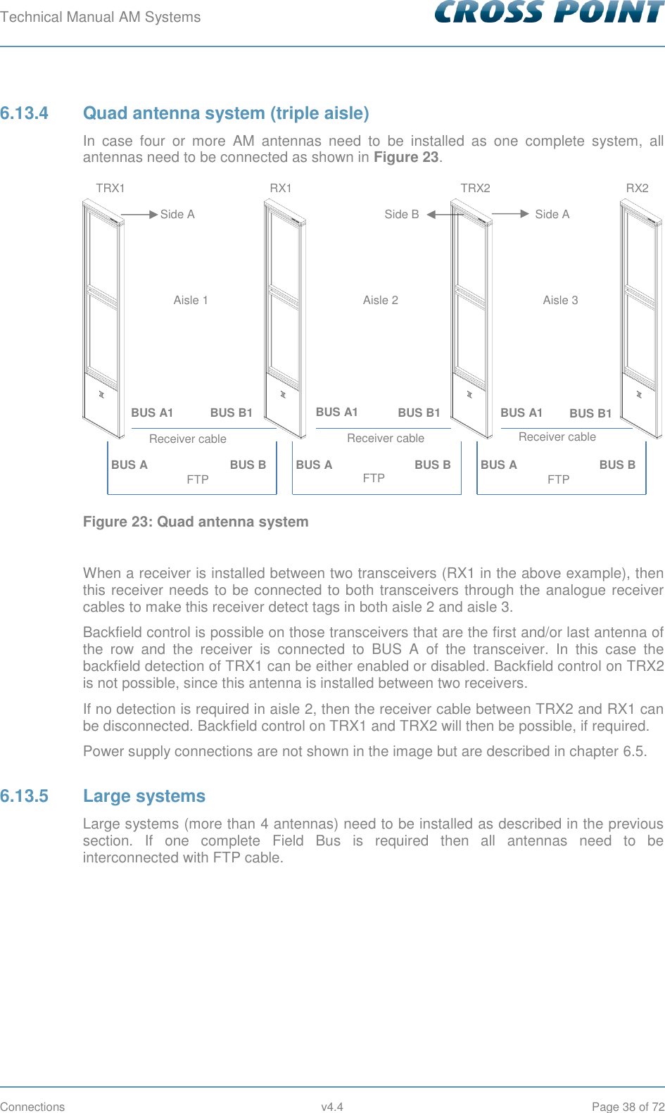
CP301MAXRXA User Manual
User Manual
Navigation menu
Upload a User Manual
Namespaces
Wiki Guide
HTML
PDF
Info
Views
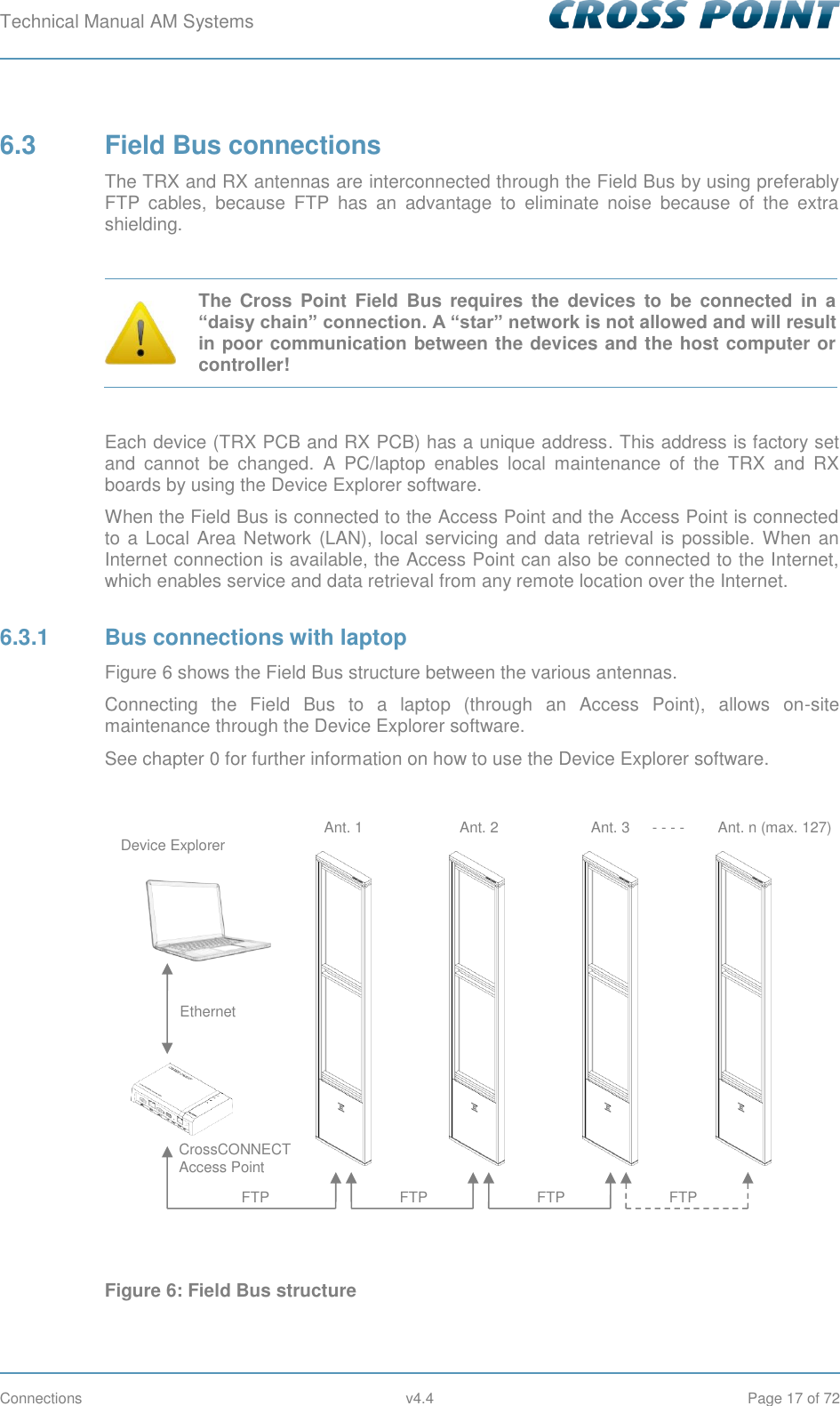
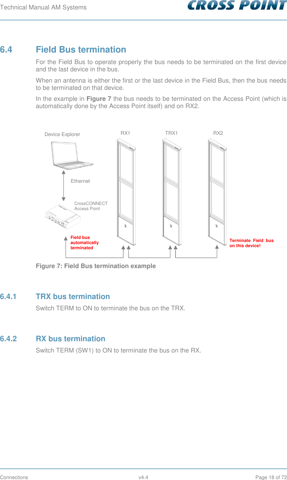
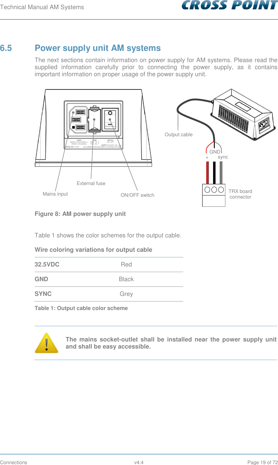
User Manual
Discussion / Help
Navigation