Cross Point CP321AMD AM DEACTIVATOR User Manual title
Cross Point b.v. AM DEACTIVATOR title
UserManual.wiki
>
Cross Point
>
CP321AMD User Manual
User Manuel
Navigation menu
Upload a User Manual
Namespaces
Wiki Guide
HTML
PDF
Info
Views
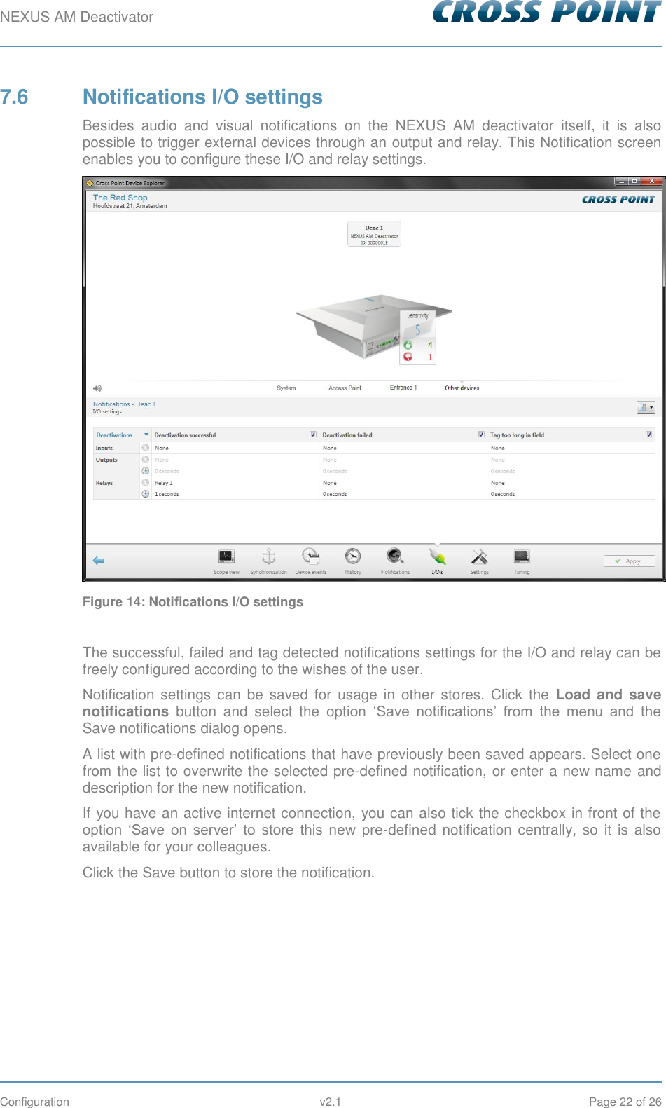
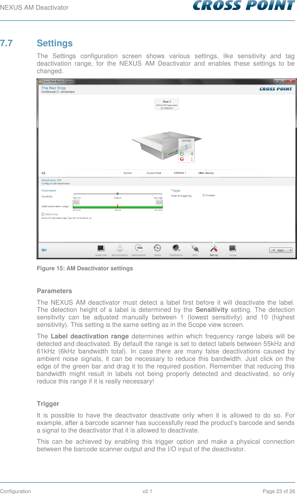
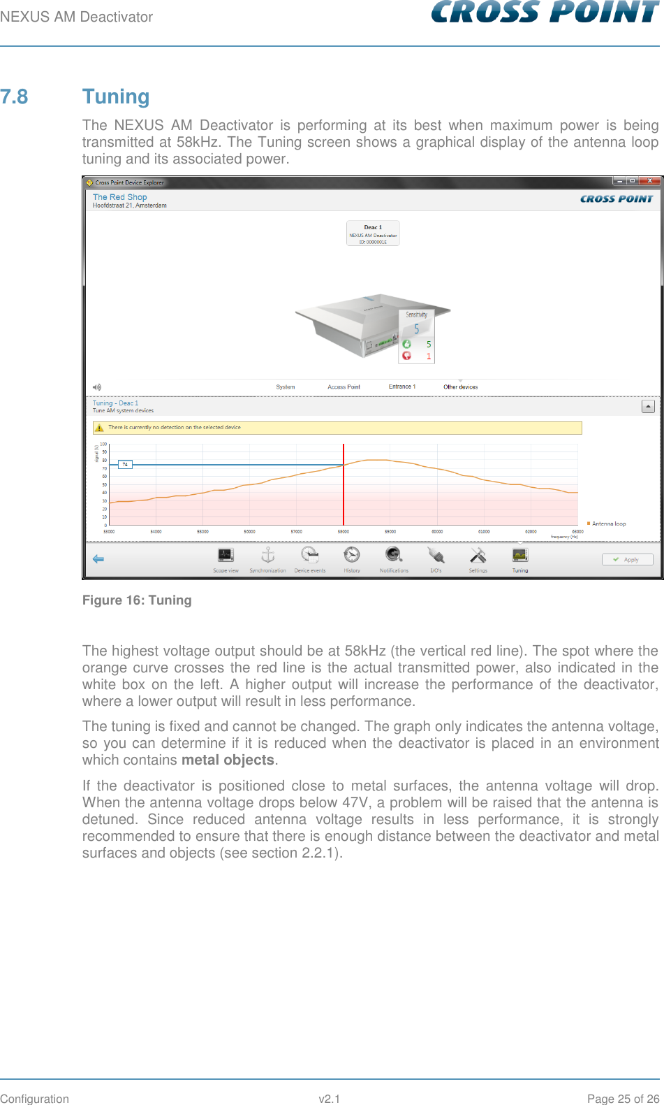
User Manual
Discussion / Help
Navigation