Crossbow Technology 001MPR2400V01 MPR2400 User Manual User s Manual
Crossbow Technology, Inc. MPR2400 User s Manual
UserManual.wiki
>
Crossbow Technology
>
001MPR2400V01 User Manual
Revised Manual
Navigation menu
Upload a User Manual
Namespaces
Wiki Guide
HTML
PDF
Info
Views
User Manual
Discussion / Help
Navigation


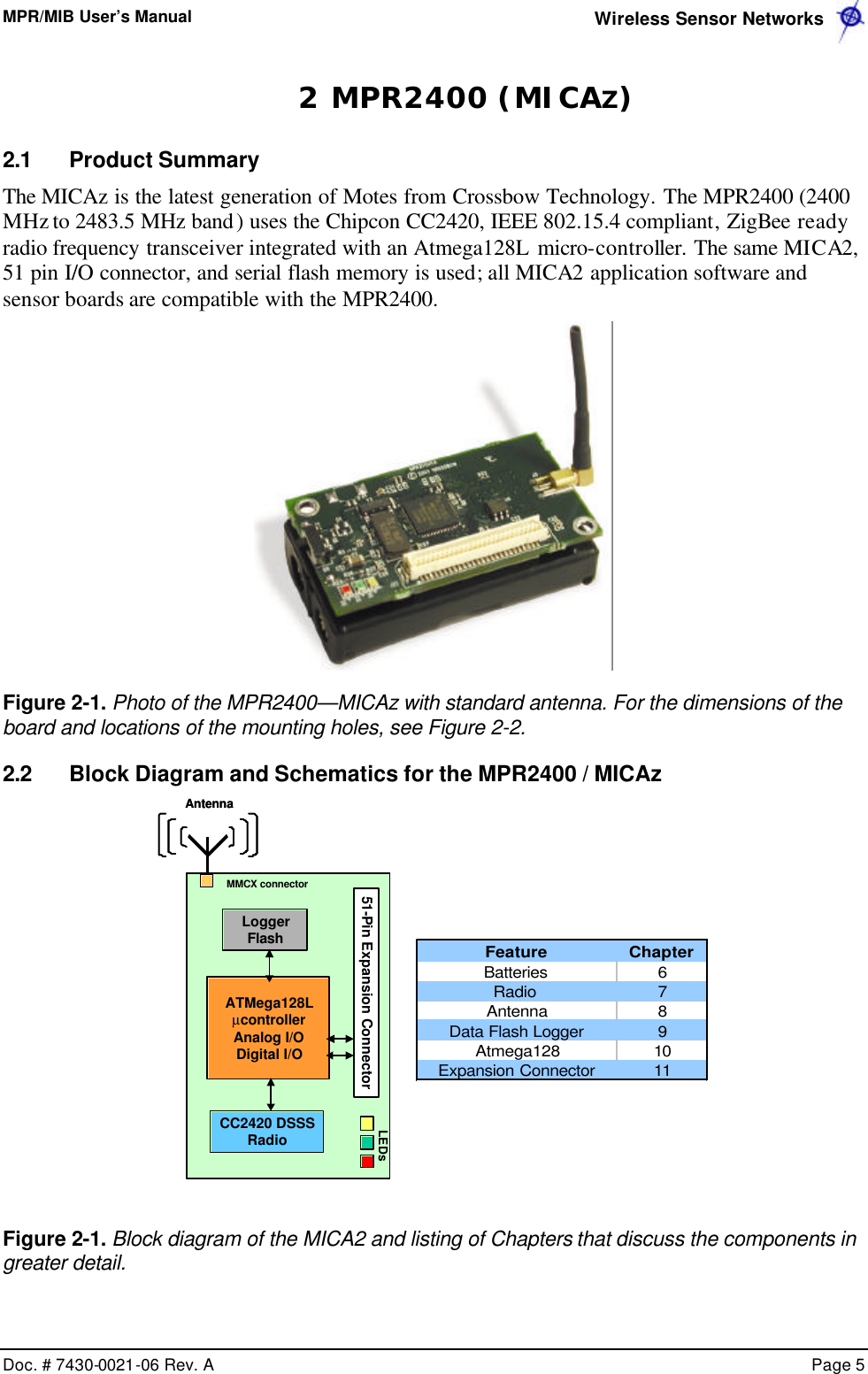
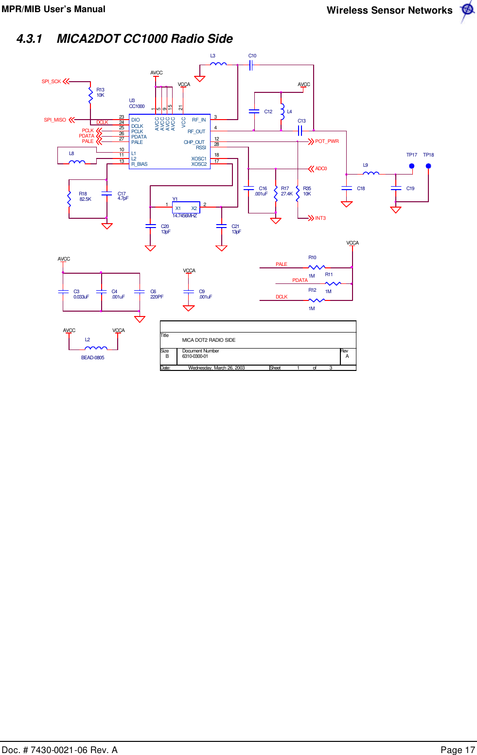
![MPR/MIB User’s Manual Wireless Sensor Networks Doc. # 7430-0021-06 Rev. A Page 11 3.2.1 Battery, Power, and ADC1 VSNSRINSTALLNOT INSTALLEDNOT INSTALLEDNOT INSTALLEDNOT INSTALLEDJ4CONN1212SW2SPDT123R810KU2LM4041-1.2123R10 OHMTP3R1R2R4R8RT1D1BAT54CBAT_MONBOARD OPTIONSR20 OHMR40 OHMADC7R51KVCCC2.1uF C1.1uFBT1BATTERY_2AA12V-V+R610KADC1R30 OHMVSNSRTHERM_PWRADC[0..7]RT110.0KR718.2K 3.2.2 CC1000 AVCCR1210KL5R111MCHP_OUT6310-0306-01 AMICA2 MPR410CB-433MHZB2 6Friday, March 21, 2003TitleSize Document Number RevDate: Sheet ofAVCCR101ML2C184.7pFRADIO DATAL4C14Y414.7456MHZ21 21C1913pFC13R91MC6.001uFPDATAL1 BEAD-0805C11.001uFL3J5MMCX123VCCR1327.4KC16.001uFAVCCJ3HDR 2 X 1 X .11212U3CC10002115915341011121318172324252627 28VCCAVCCAVCCAVCCAVCCRF_INRF_OUTL1L2CHP_OUTR_BIAS XOSC1XOSC2DIODCLKPCLKPDATAPALE RSSIC12C7.001uFC17RADIO CONTROLVCCC15AVCCPALEPDATAC100.033uFC50.033uFDCLKPCLKSPI_SCKSPI_MOSISPI_MISOCHP_OUTADC0 (RSSI)C9220PFPALESPI_MISOPCLKPDATAPALER1482.5KADC0C2013pFSPI_SCKVCCVCCC8220PFDCLK](https://usermanual.wiki/Crossbow-Technology/001MPR2400V01/User-Guide-477499-Page-13.png)
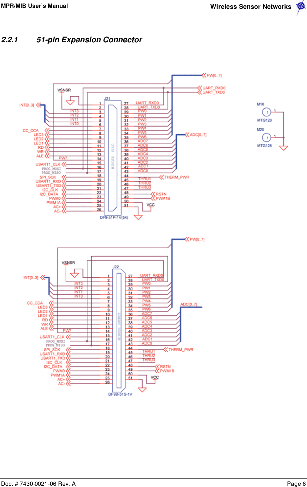
![MPR/MIB User’s Manual Wireless Sensor Networks Doc. # 7430-0021-06 Rev. A Page 12 3.2.3 51-pin Expansion Connector: Location J21 ADC4AC+SPI_SCKUART_RXD0USART1_RXDDESCRIPTIONADC3PW2ALEPWM1AADC2BAT_MONGNDVSNSRINT3INT2INT1INT0BAT_MONLED3LED2LED1RDWRALEPW7USART1_CLKPROG_MOSIPROG_MISOSPI_SCKUSART1_RXDUSART1_TXDI2C_CLKI2C_DATAPWM0PWM1AAC+AC-NAMEADC7PW5INT1ADC1PINTHRU3LED3LED1ADC[0..7]I2C_CLKPWM1BAC-PWM0 RSTNUART_TXD0RDINT2ADC5INT3THERM_PWRPW4UART_RXD0THRU1USART1_CLKPROG_MISOADC6PW1INT[0..3]1234567891011121314151617181920212223242526VCCHIROSE PLUGJ21DF9-51P-1V(54)123456789101112131415161718192021222324252627282930313233343536373839404142434445464748495051WRPROG_MOSITHRU2LED2PW0PW6ADC0VSNSRI2C_DATAPW7INT0 PW3UART_TXD0USART1_TXDGROUNDSENSOR SUPPLYGPIOGPIOGPIOGPIOBATTERY VOLTAGE MONITOR ENABLELED3LED2LED1GPIOGPIOGPIOPOWER CONTROL 7USART1 CLOCKSERIAL PROGRAM MOSISERIAL PROGRAM MISOSPI SERIAL CLOCKUSART1 RX DATAUSART1 TX DATAI2C BUS CLOCKI2C BUS DATAGPIO/PWM0GPIO/PWM1AGPIO/AC+GPIO/AC-PW[0..7] 3.2.4 51-pin Expansion Pads: Location J22 THRU1PW4AC+ALETHRU2PROG_MISOUART_TXD0PWM0I2C_DATAADC[0..7]PW1PW[0..7]I2C_CLKADC6THRU3PW2USART1_RXDSPI_SCKBAT_MON6310-0306-01 AMICA2 MPR410CB-433MHZCROSSBOW TECHNOLOGY. INC.B4 6Friday, March 21, 2003TitleSize Document Number RevDate: Sheet ofPW6INT0UART_RXD0UART_TXD0PW0PW1PW2PW3PW4PW5PW6ADC7ADC6ADC5ADC4ADC3ADC2ADC1ADC0THERM_PWRTHRU1THRU2THRU3RSTNPWM1BVCCGNDADC5PWM1BAC-ADC3PWM1AINT1LED1ADC0USART1_CLK ADC1THERM_PWRNAME DESCRIPTIONADC7USART1_TXDM20MTG12811VSNSRINT3PROG_MOSIADC4HIROSE SOCKETJ22DF9B-51S-1V123456789101112131415161718192021222324252627282930313233343536373839404142434445464748495051M18MTG12811INT[0..3]WRPW3RSTNPW7UART_0 RECEIVEUART_0 TRANSMITPOWER CONTROL 0POWER CONTROL 1POWER CONTROL 2POWER CONTROL 3POWER CONTROL 4POWER CONTROL 5POWER CONTROL 6ADC INPUT 7 - BATTERY MONITOR/JTAG TDIADC INPUT 6 / JTAG TDOADC INPUT 5 / JTAG TMSADC INPUT 4 / JTAG TCKADC INPUT 3ADC INPUT 2ADC INPUT 1ADC INPUT 0 / RSSI MONITORTEMP SENSOR ENABLETHRU CONNECT 1THRU CONNECT 2THRU CONNECT3RESET (NEG)GPIO/PWM1BDIGITAL SUPPLYGROUNDLED2VCCUART_RXD0PINPW5PW0ADC2INT2LED3RD27282930313233343536373839404142434445464748495051](https://usermanual.wiki/Crossbow-Technology/001MPR2400V01/User-Guide-477499-Page-14.png)
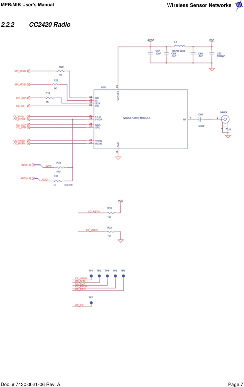
![MPR/MIB User’s Manual Wireless Sensor Networks Doc. # 7430-0021-06 Rev. A Page 13 3.2.5 ATMega128L VCCBAT_MONC23.1uFSPI_MISOINT0PW6RDINT3ADC7PWM1AC3613pFR2010KVSNSRADC5LED3PW0Y332.768KHZ43 21X2GND GNDX1UART_TXD0I2C_CLKLED1AC+PW5R1610KPW3C22.1uFU7ATMEGA128L5150494847464544101112131415161735363738394041422526272829303132234567896160595857565554646212024233334431819PA0/AD0PA1/AD1PA2/AD2PA3/AD3PA4/AD4PA5/AD5PA6/AD6PA7/AD7PB0/SSPB1/SCKPB2/MOSIPB3/MISOPB4/OC0PB5/OC1APB6/OC1BPB7/OC1CPC0/A8PC1/A9PC2/A10PC3/A11PC4/A12PC5/A13PC6/A14PC7/A15PD0/I2C_CLKPD1/I2C_DATAPD2/RXD1PD3/TXD1PD4/IC1PD5/XCK1PD6/T1PD7/T2PE0/RXD0PE1/TXD0PE2/XCK0PE3/OC3APE4/OC3BPE5/OC3CPE6/T3PE7/IC3PF0/ADC0PF1/ADC1PF2/ADC2PF3/ADC3PF4/TCKPF5/TMSPF6/TDOPF7/TDIAVCCAREFPENRSTXTAL1XTAL2PG0/WRPG1/RDPG2/ALEPG3/TOSC2PG4/TOSC1USART1_CLKC21.1uFFLASH_CSWRSPI_SCK ADC2ADC3R2110KPW1CHP_OUTTHERM_PWRPWM1BRSTNADC4VCCPALEAC-INT2LED2ADC1PWM0USART1_RXDPW4R180 OHMSERIAL_IDR15470UART_RXD0INT[0..3]C3513pFI2C_DATAPW[0..7]6310-0306-01 AMICA2 MPR410CB-433MHZCROSSBOW TECHNOLOGY. INC.B5 6Friday, March 21, 2003TitleSize Document Number RevDate: Sheet ofADC0ADC6ALEPDATAPCLKY27.3728MHZ2341X2X2X1X1PW7ADC[0..7]SPI_MOSIUSART1_TXDPW2INT1](https://usermanual.wiki/Crossbow-Technology/001MPR2400V01/User-Guide-477499-Page-15.png)
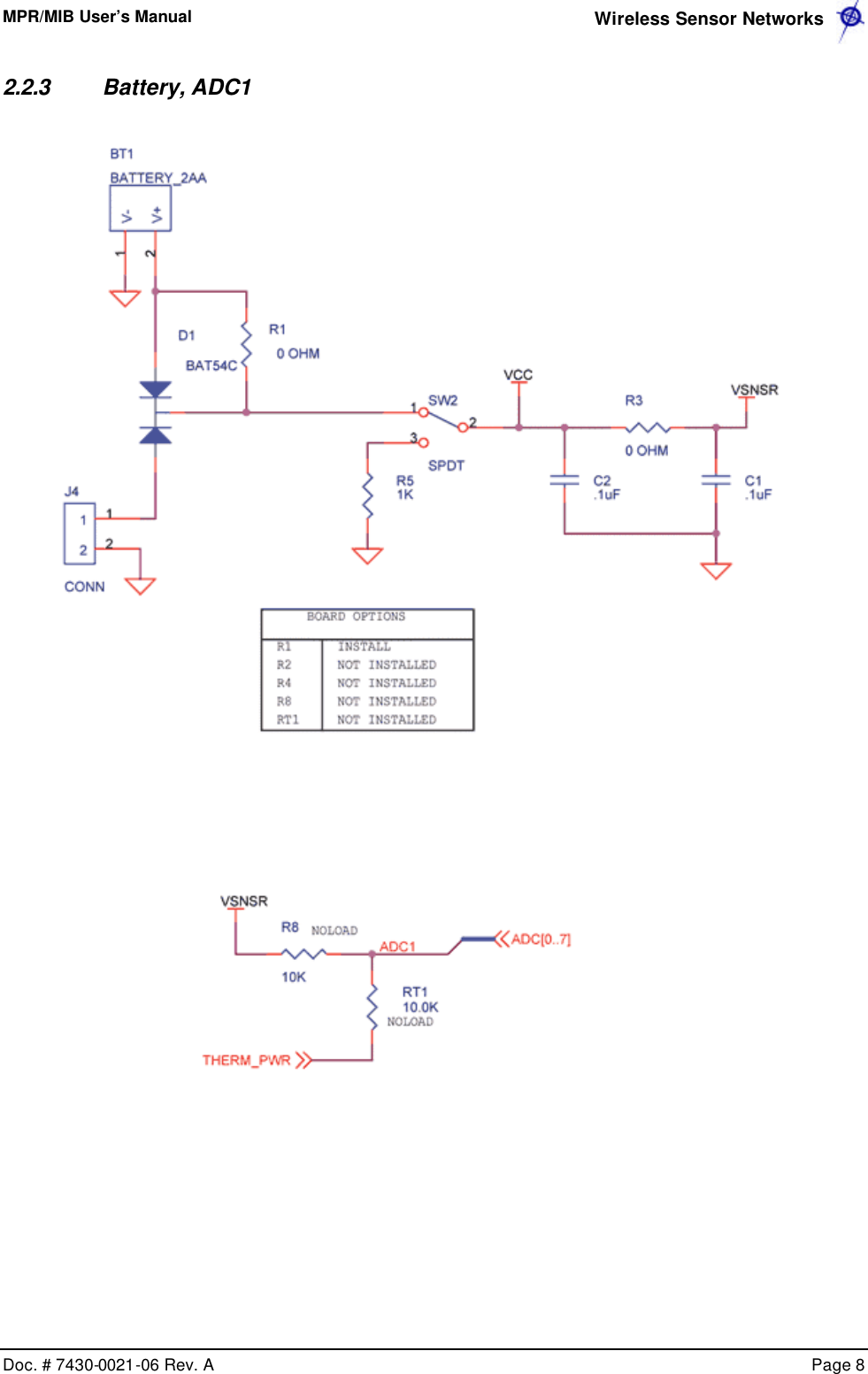
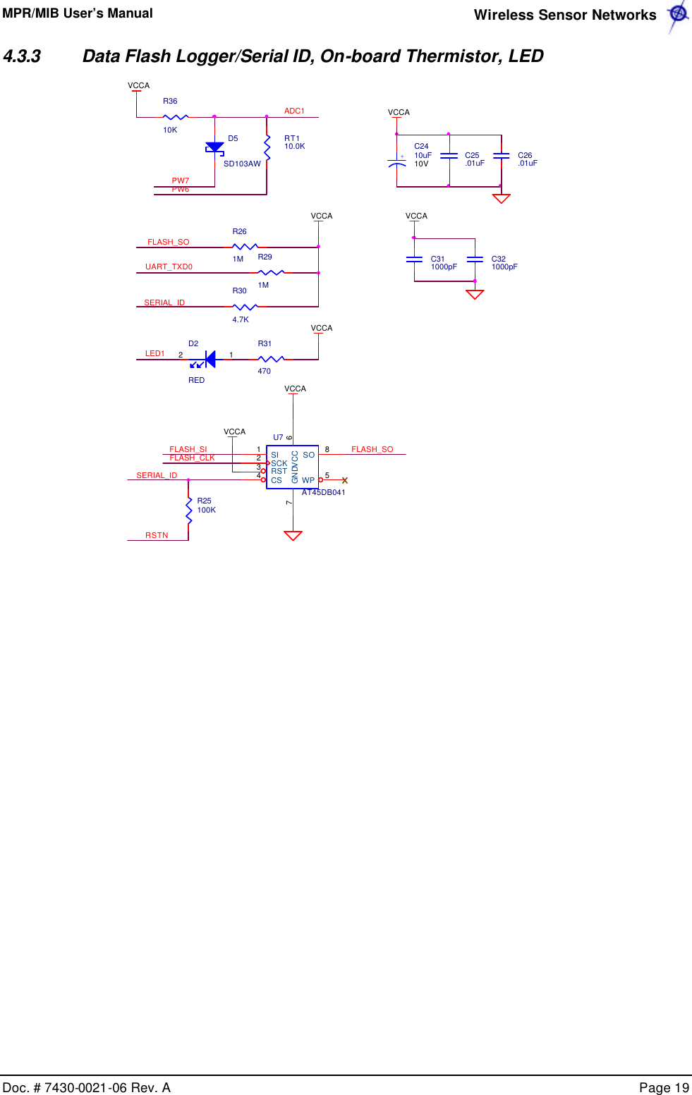
![MPR/MIB User’s Manual Wireless Sensor Networks Doc. # 7430-0021-06 Rev. A Page 14 3.2.6 Flash Memory, Serial ID, LEDs, USART SERIAL_IDVCCPCLKPDATAPALED2RED126310-0306-01 AMICA2 MPR410CB-433MHZCROSSBOW TECHNOLOGY. INC.B6 6Friday, March 21, 2003TitleSize Document Number RevDate: Sheet ofC27.01uFFLASH INTERFACEUSART1_CLKC28.01uFRADIO CONTROLC321000pFR234.7KVCCC30.01uFUSART1_TXDU5AT45DB0411234 58SISCKRSTCS WPSOUART INTERFACEUART_RXD0UART_TXD0CONTROL INTERFACER191MLED2U6DS2401P2DQD4YELLOW12USART1_RXD+C2410uF10VR27470I2C_CLKI2C_DATASPI_SCKSPI_MOSISPI_MISOCHP_OUTADC0(RSSI)RADIO DATALED1ADC7C29.01uFC25.01uFR25470R221MVCCC331000pFLED3FLASH_CSFLASH_CSVCCD3GREEN12FLASH_SIFLASH_SOFLASH_CLKSERIAL_IDSENSOR INTERFACER26470PW[0..7]ADC[1..6]USART1_RXDVCCVCC MONITORUART_TXD0C311000pF C341000pFC26.01uF](https://usermanual.wiki/Crossbow-Technology/001MPR2400V01/User-Guide-477499-Page-16.png)
![MPR/MIB User’s Manual Wireless Sensor Networks Doc. # 7430-0021-06 Rev. A Page 18 4.3.2 MIC2DOT ATMega128L, ADC Interfaces, Battery PW5Y532.768KHZ321NCX2X1SPI_MOSIINT0SPI_SCKPDATAVCCAR2210KPWM1BPW[0..7]R21470ADC1POT_PWRLED2UART_RXD0INT1ALEADC6ADC5AC+LED3VCCADC_BOOST_SHDNPW7PWM0SERIAL_IDSPI_MISOADC3PWM1AINT2Y44.000MHZ65213 4X1GNDGNDX1X2 X2PW2ADC4RSTNU6ATMEGA128LMLF21522253635150494847464544101112131415161735363738394041422526272829303132234567896160595857565554646212024233334431819VCCVCCGNDGNDGNDPA0/AD0PA1/AD1PA2/AD2PA3/AD3PA4/AD4PA5/AD5PA6/AD6PA7/AD7PB0/SSPB1/SCKPB2/MOSIPB3/MISOPB4/OC0PB5/OC1APB6/OC1BPB7/OC1CPC0/A8PC1/A9PC2/A10PC3/A11PC4/A12PC5/A13PC6/A14PC7/A15PD0/INT0PD1/INT1PD2/RXD1PD3/TXD1PD4/IC1PD5/XCK1PD6/T1PD7/T2PE0/RXD0PE1/TXD0PE2/XCK0PE3/OC3APE4/OC3BPE5/OC3CPE6/T3PE7/IC3PF0/ADC0PF1/ADC1PF2/ADC2PF3/ADC3PF4/TCKPF5/TMSPF6/TDOPF7/TDIAVCCAREFPENRSTXTAL1XTAL2PG0/WRPG1/RDPG2/ALEPG3/TOSC2PG4/TOSC1ADC7C23.1uFR2810KPALEADC2GPS_ENAC22.1uFPW3 AC-PCLKLED1PW6RDVCCAPW0ADC[0..7]SPI_MOSII2C1_DATAFLASH_SIFLASH_SOR2710KPW1ADC0FLASH_CLKUART_TXD0PW4I2C1_CLKWRINT3 INT0TP8TP19ADC[0..7]TP10TP7PW1SPI_SCKRSTNADC3TP6 TP11TP13PW0TP20ADC5TP4VCCAADC2PWM1BTP15BT1BATTERY1 2TP2VCCATP9TP1ADC7ADC6TP21GPS_ENAPW[0..7]ADC4TP5TP3 TP12TP14INT1UART_TXD0UART_RXD0](https://usermanual.wiki/Crossbow-Technology/001MPR2400V01/User-Guide-477499-Page-20.png)


![MPR/MIB User’s Manual Wireless Sensor Networks Doc. # 7430-0021-06 Rev. A Page 25 7 RADIOS 7.1 MICA2 and MICA2DOT 7.1.1 Radio Considerations The radio on the MICA2 and MICA2DOT is capable of multiple channel operation, within the intended band of operation. The MPR420/MPR520 can span up to 4 channels of operation in the 315 MHz band, the MPR410/MPR510 can span up to 4 channels of operation in the 433 MHz band (433.05–434.79 MHz). The MPR400/MPR500 can operate in two frequency regions: 868–870 MHz (up to 4 channels) and 902–928 MHz (up to 54 channels). The actual number of possible channels is higher for all the MICA2/MICA2DOT motes. However, it is recommended that the adjacent channel spacing should be at least 500 kHz to avoid adjacent channel interference thereby reducing the number of available channels. A tutorial on how to change frequency is available at http://www.tinyos.net/tinyos-1.x/doc/mica2radio/CC1000.html. 7.1.2 Radio Transmission Power The radio on the MICA2/MICA2DOT can be adjusted for a range of output power levels. The register in the radio that controls the RF power level is designated PA_POW at address 0x0B, and the values and their corresponding RF outputs are provided on Table 7-1 below. It shows the closest programmable value for output powers in steps of 1 dBm. For power down mode the Chipcon datasheet says, “the PA_POW should be set to 00h [0x00] for minimum leakage current.”](https://usermanual.wiki/Crossbow-Technology/001MPR2400V01/User-Guide-477499-Page-27.png)
![MPR/MIB User’s Manual Wireless Sensor Networks Doc. # 7430-0021-06 Rev. A Page 40 13.4.5 Schematics HIROSE SOCKETJ1DF9B-51S-1V123456789101112131415161718192021222324252627282930313233343536373839404142434445464748495051PROG_MISOADC4INT0PW2PW7PW1ADC4PROG_MOSIINT0USART1_RXDPW[0..7]INT2AC+VCCTHERM_PWRVSNSRPWM0VCCPW5M1MTG12811ADC[0..7]INT3PWM1BAC+LED1THRU1USART1_TXDLED3ALEPW1VSNSRAC-ADC6USART1_CLKAC-PWM1BHIROSE PLUGJ2DF9-51P-1V(54)123456789101112131415161718192021222324252627282930313233343536373839404142434445464748495051ADC5USART1_RXD THRU2PROG_MISOLED2PW3PW6WRADC3RSTNPROG_MOSIINT[0..3]THERM_PWRPW7PWM0THRU2INT[0..3]INT2ADC2UART_TXD0PW0THRU3LED3INT1BAT_MONADC7PW4PW5THRU3ADC1LED1USART1_CLKI2C_CLKADC3I2C_DATAI2C_CLKPWM1AADC1UART_RXD0ADC0UART_RXD0PW[0..7]INT1PW3SPI_SCKUART_RXD0ADC7ADC5BAT_MONLED2RDI2C_DATASPI_SCKUART_TXD0RDALEPW0INT3PWM1AUART_TXD0THRU1RSTNUSART1_TXDADC[0..7]PW2PW4PW6ADC6ADC0 M2MTG12811ADC2WR](https://usermanual.wiki/Crossbow-Technology/001MPR2400V01/User-Guide-477499-Page-42.png)
![MPR/MIB User’s Manual Wireless Sensor Networks Doc. # 7430-0021-06 Rev. A Page 42 13.4.6 RS-232, MICA2DOT, and Ext. Power Interface. M4 MTG128 11LPT1_MISO J4DB25-M-RA 51741631521412071961810229218231124122513ADC5VCCINT1 J3HDR2X51 23 45 67 89 10VCCADC[0..7] RSTN RS232_TX M6 MTG128 11C1.1uF50VTHERM_PWR ADC6RSTN RS232_RX TP6 J6DB9 -F-RA594837261SPI_SCK ADC6INT0 TP5PWM1B TP7 PIN OUTER J7PJ -014D231UART_TXD0 U1LMS8117-3.3 3124VIN ADJVOUTGNDPW1 M3 MTG12811D1B2100 +C210uF35VTDITP9 TCKTDOTMSPW0 J5DOT2 1234567891011121314151617181912345678910111213141516171819ADC4ADC26310-0304-01AMIB500CA MICA PROG BOARD CROSSBOW TECHNOLOGY. INC. B2 3Wednesday, March 26, 2003 Title Size Document NumberRevDate: SheetofLPT1_MOSI ADC3ADC4VCCLPT1_RST UART_RXD0 TP8 ADC7ADC7M5 MTG12811ADC5LPT1_SCK](https://usermanual.wiki/Crossbow-Technology/001MPR2400V01/User-Guide-477499-Page-44.png)