Crossbow Technology 002MXP2X0 Wireless Network Sensor User Manual MXP2X0 User Manual
Crossbow Technology, Inc. Wireless Network Sensor MXP2X0 User Manual
Users Manual
Crossbow Engineering Wireless
AUTHORS: AAFZALI PART NUMBER: MXP2X0_User_Manual.doc
DATE: 2006.06.23 PAGE: 1 of 6
MXP200 and MXP210
User’s Manual
Document Part Number: 7430 – 0528 - 1
Revision: A
--
CROSSBOW TECHNOLOGY INC., Proprietary and Confidential
—
NOT TO BE DISTRIBUTED OR DUPLICATED WITHOUT PERMISSION
Crossbow Engineering Wireless
AUTHORS: AAFZALI PART NUMBER: MXP2X0_User_Manual.doc
DATE: 2006.06.23 PAGE: 2 of 6
Revision Date Author Comments
A Oct 10, 2006 Afshin Afzali Initial Creation

Crossbow Engineering Wireless
AUTHORS: AAFZALI PART NUMBER: MXP2X0_User_Manual.doc
DATE: 2006.06.23 PAGE: 3 of 6
Table of Contents
1 MXP200 INSTALLATION: 4
2 MXP210 INSTALLATION: 5
COMPLIANCE STATEMENT: 6
Crossbow Engineering Wireless
AUTHORS: AAFZALI PART NUMBER: MXP2X0_User_Manual.doc
DATE: 2006.06.23 PAGE: 4 of 6
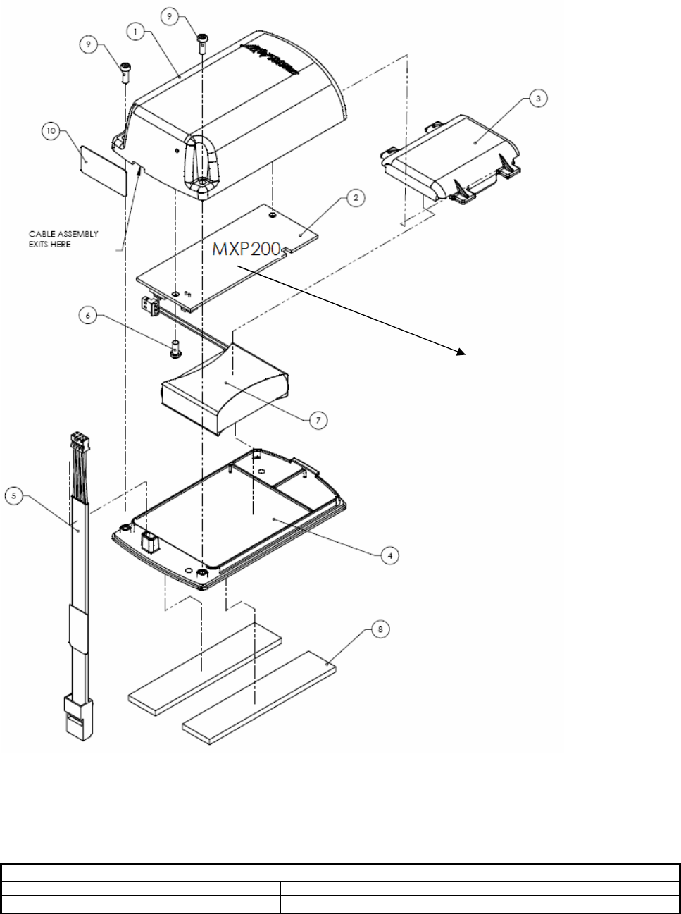
1 MXP200 Installation:
MXP200 SHOULD BE ASSEMBLED INSIDE CARDIO MOTE PER FIG1 AND ASSEMBLY MUST BE PROPERLY
PACKAGED TO AVOID DAMAGE DURING SHIPMENT.
FIG1 – MXP200 Assembly Procedure inside Cardio Mote
MXP200
Crossbow Engineering Wireless
AUTHORS: AAFZALI PART NUMBER: MXP2X0_User_Manual.doc
DATE: 2006.06.23 PAGE: 5 of 6
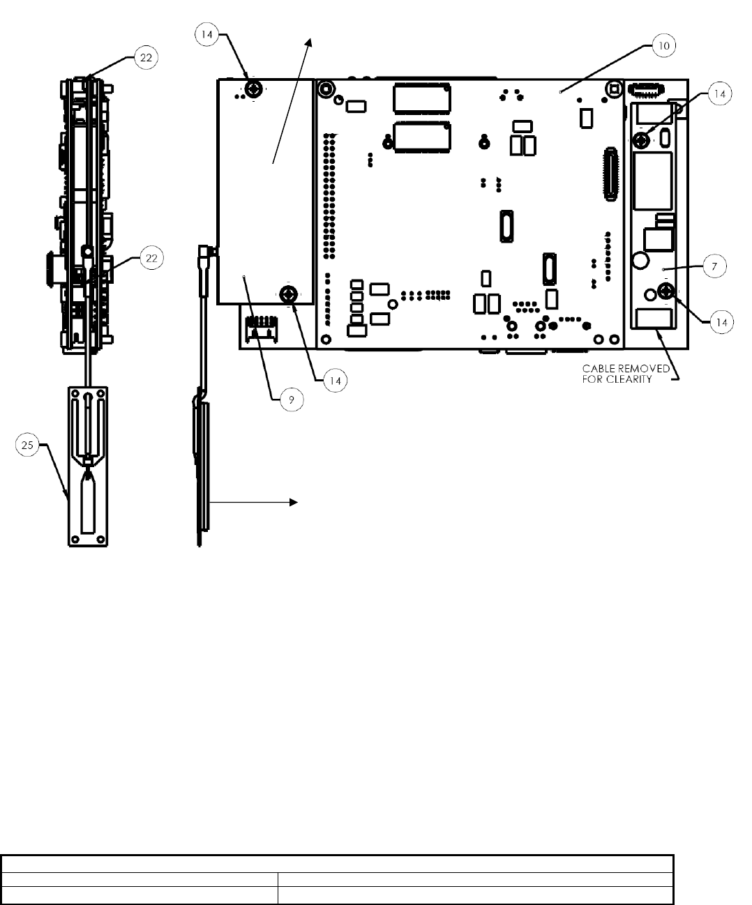
2 MXP210 Installation:
MXP200 SHOULD BE ASSEMBLED INSIDE STRENGHT MOTE PER FIG2 AND ASSEMBLY MUST BE PROPERLY
PACKAGED TO AVOID DAMAGE DURING SHIPMENT.
FIG2 – MXP210 Assembly Procedure inside Strength Mote
MXP210
MXP210 Antenna

Crossbow Engineering Wireless
AUTHORS: AAFZALI PART NUMBER: MXP2X0_User_Manual.doc
DATE: 2006.06.23 PAGE: 6 of 6
Compliance Statement:
This device has been designed, constructed, and tested for compliance with FCC Rules that regulate intentional and unintentional
radiators. The user is not permitted to make any modifications to this equipment without express approval from Crossbow
Technology Inc. Doing so will void the user’s authority to operate this equipment.
This device complies with Part 15 of the FCC Rules. Operation is subject to the following two conditions: (1) this device may not
cause harmful interference, and (2) this device must accept any interference received, including interference that may cause undesired
operation
This equipment has been tested and found to comply with the limits for a Class A digital device, pursuant to part 15 of the FCC
Rules. These limits are designed to provide reasonable protection against harmful interference when the equipment is operated in a
commercial environment. This equipment generates, uses, and can radiate radio frequency energy and, if not installed and used in
accordance with the instruction manual, may cause harmful interference to radio communications. Operation of this equipment in a
residential area is likely to cause harmful interference in which case the user will be required to correct the interference at his own
expense.
This device has been designed to operate with the antennas listed below, and having a maximum gain of 2.2 dBi. Antennas not
included in this list or having a gain greater than 2.2 dBi are strictly prohibited for use with this device. The required antenna
impedance is 50 ohms.
- Internal PCBA Antenna which has been developed on the board
- External Antenna with a gain of 2.2dBi or less
To reduce potential radio interference to other users, the antenna type and its gain should be so chosen that the equivalent
isotropically radiated power (e.i.r.p.) is not more than that permitted for successful communication.
ICES-003 Statement: This Class B digital apparatus complies with Canadian ICES-003.