Crossbow Technology 003BU2400 BU2400 User Manual 7430 0021 07 B
Crossbow Technology, Inc. BU2400 7430 0021 07 B
UserManual.wiki
>
Crossbow Technology
>
003BU2400 User Manual
>
Users Manual 1
Contents
1.
Users Manual 1
2.
Users Manual 2
Users Manual 1
Navigation menu
Upload a User Manual
Namespaces
Wiki Guide
HTML
PDF
Info
Views
User Manual
Discussion / Help
Navigation

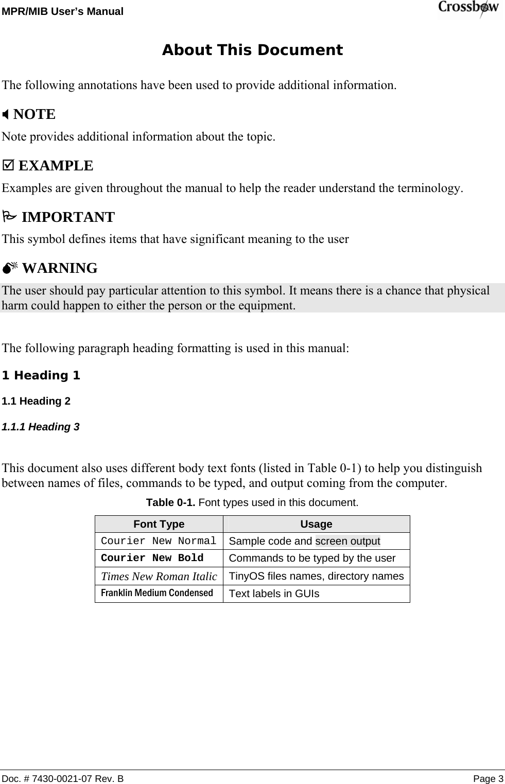
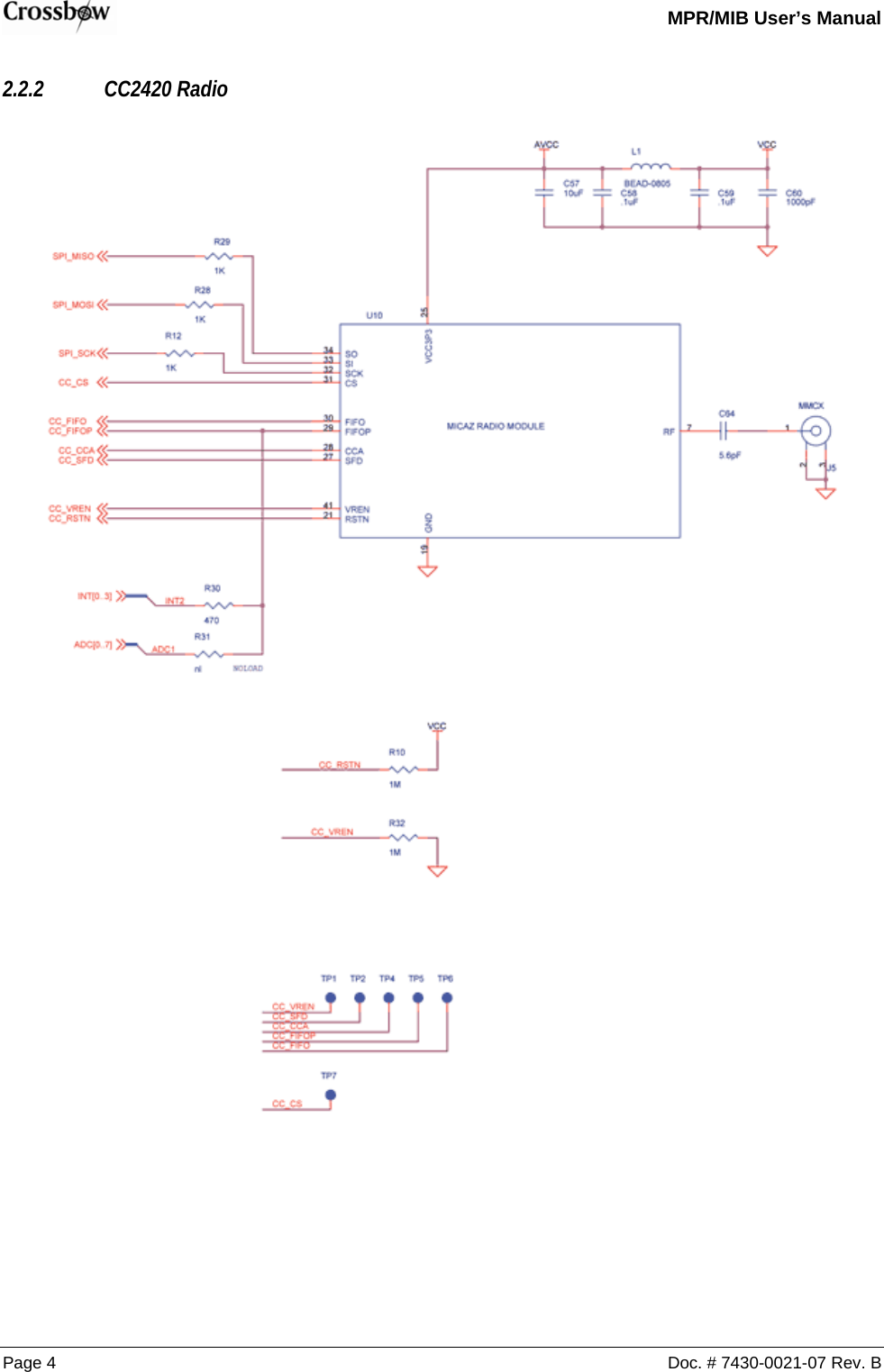
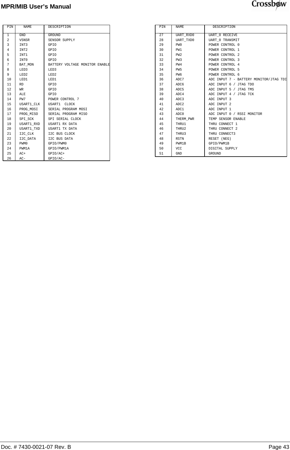
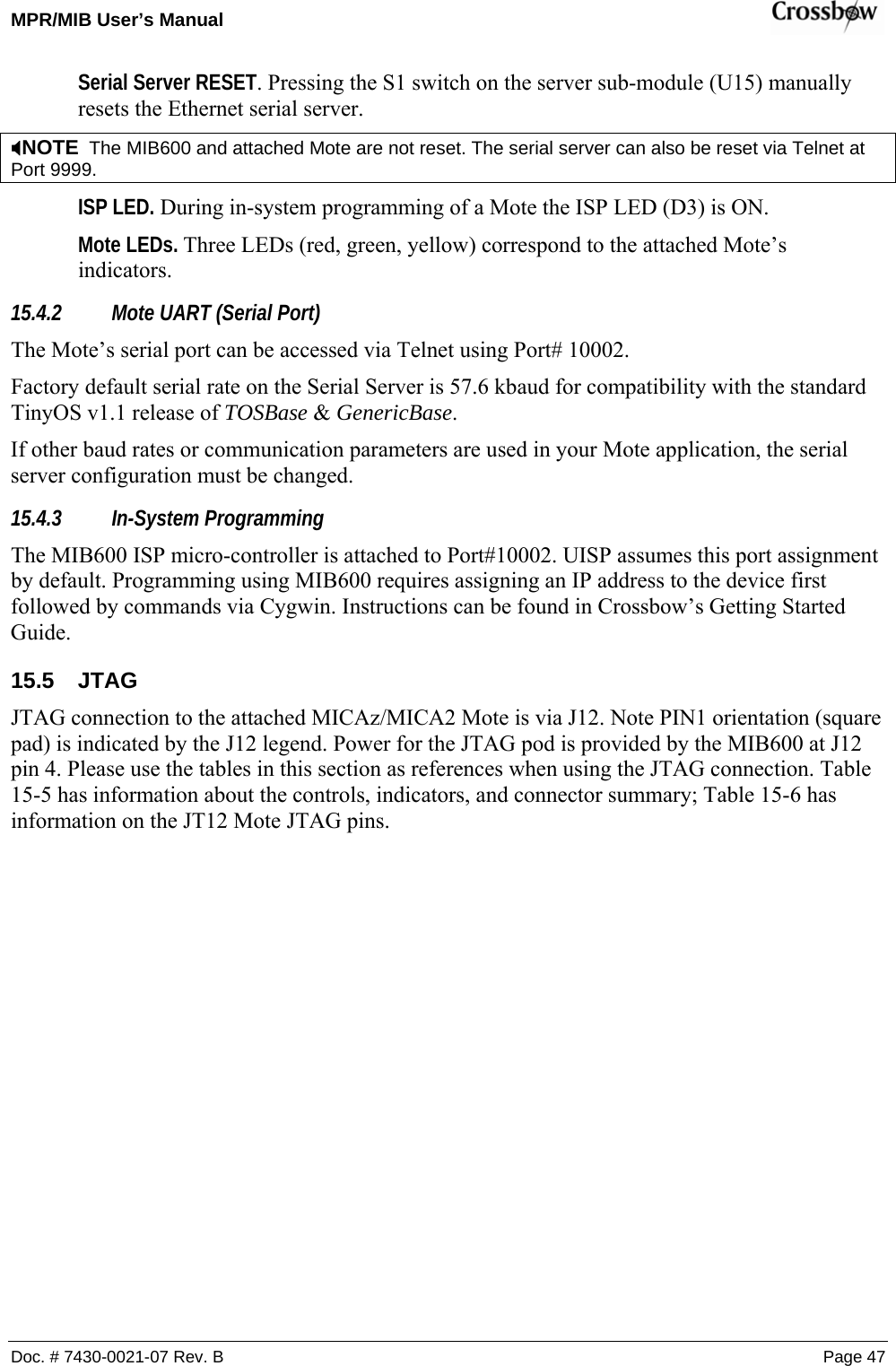
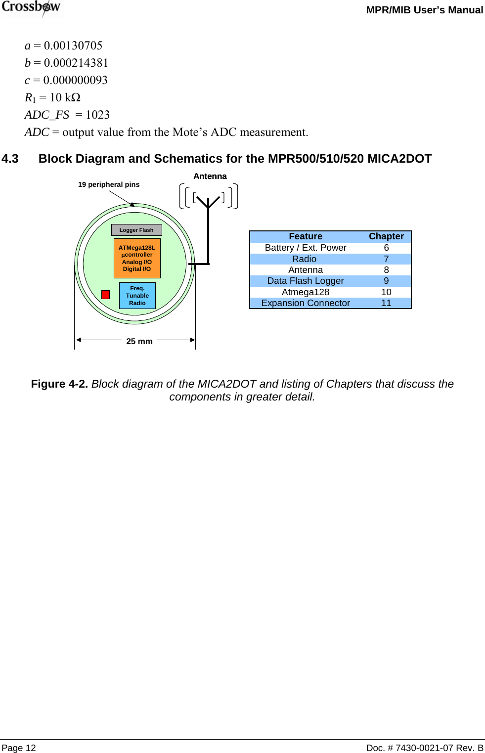
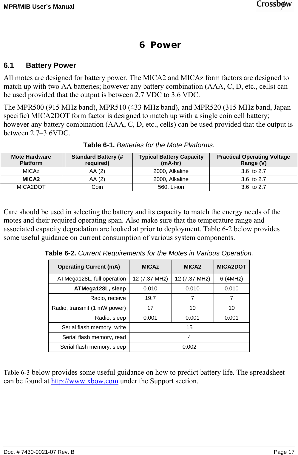
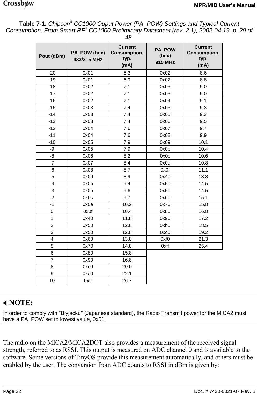
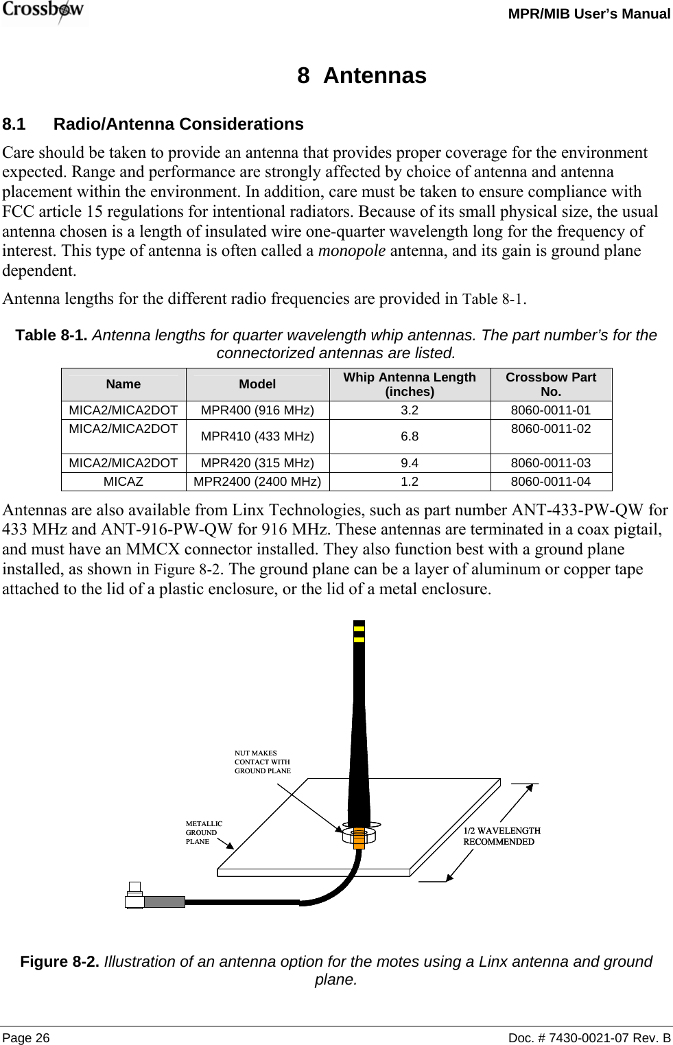
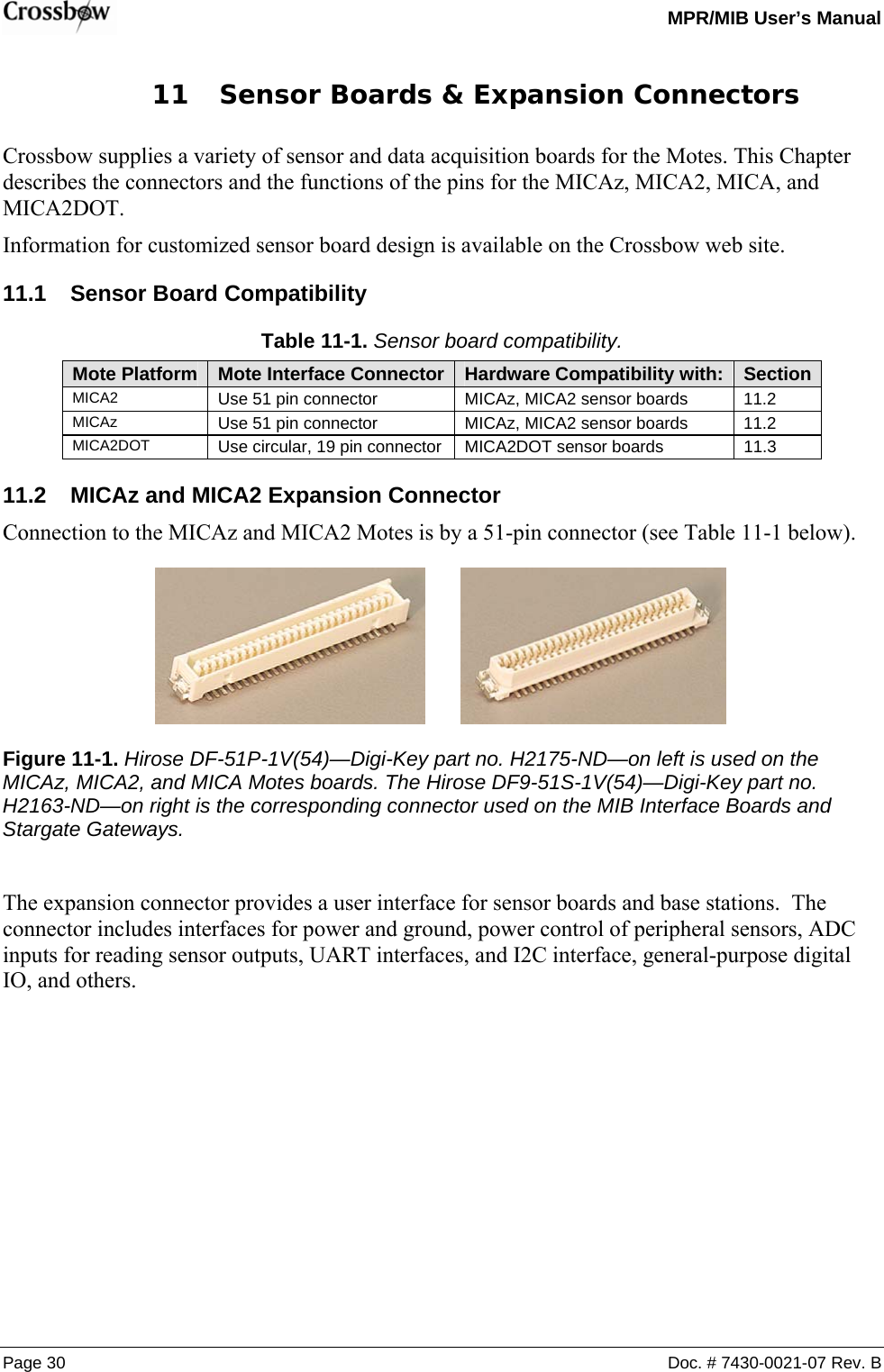
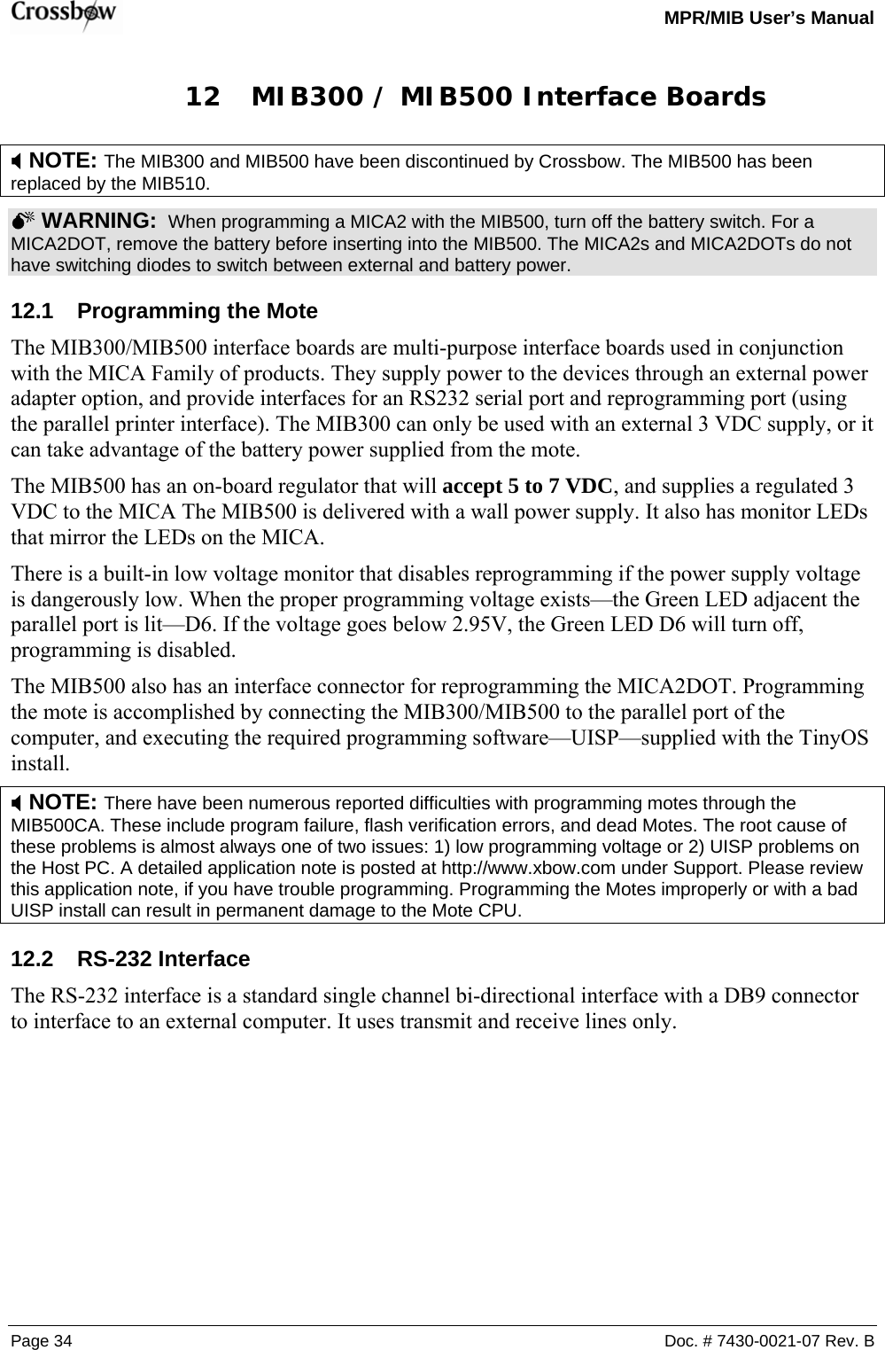
![MPR/MIB User’s Manual Doc. # 7430-0021-07 Rev. B Page 7 3.2.1 Battery, Power, and ADC1 VSNSINSTALLNOT INSTALLEDNOT INSTALLEDNOT INSTALLEDNOT INSTALLEDJ4CONN1212SW2SPDT123R810KU2LM4041-1.2123R10 OHMTP3R1R2R4R8RT1D1BAT54CBAT_MONBOARD OPTIONSR20 OHMR40 OHMADC7R51KVCCC2.1uF C1.1uFBT1BATTERY_2AA12V-V+R610KADC1R30 OHMVSNSRTHERM_PWRADC[0..7]RT110.0KR718.2K 3.2.2 CC1000 AVCCR1210KL5R111MCHP_OUT6310-0306-01 AMICA2 MPR410CB-433MHZB26Friday, March 21, 2003TitleSize Document Number RevDate: Sheet ofAVCCR101ML2C184.7pFRADIO DATAL4C14Y414.7456MHZ21 21C1913pFC13R91MC6.001uFPDATAL1 BEAD-0805C11.001uFL3J5MMCX123VCCR1327.4KC16.001uFAVCCJ3HDR 2 X 1 X .11212U3CC100021159153410111213 18172324252627 28VCCAVCCAVCCAVCCAVCCRF_INRF_OUTL1L2CHP_OUTR_BIAS XOSC1XOSC2DIODCLKPCLKPDATAPALE RSSIC12C7.001uFC17RADIO CONTROLVCCC15AVCCPALEPDATAC100.033uFC50.033uFDCLKPCLKSPI_SCKSPI_MOSISPI_MISOCHP_OUTADC0 (RSSI)C9220PFPALESPI_MISOPCLKPDATAPALER1482.5KADC0C2013pFSPI_SCKVCCVCCC8220PFDCLK](https://usermanual.wiki/Crossbow-Technology/003BU2400.Users-Manual-1/User-Guide-716628-Page-13.png)
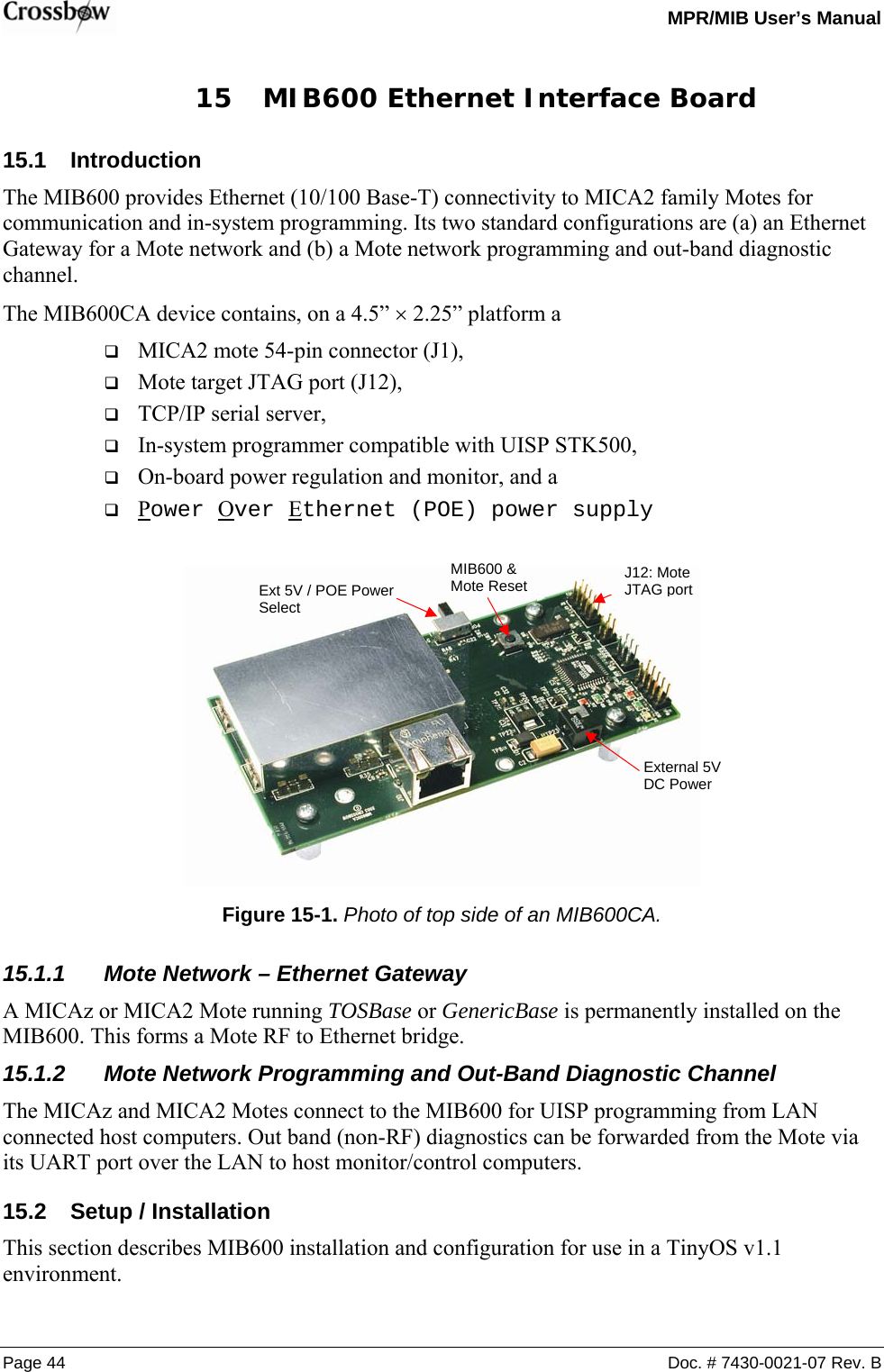
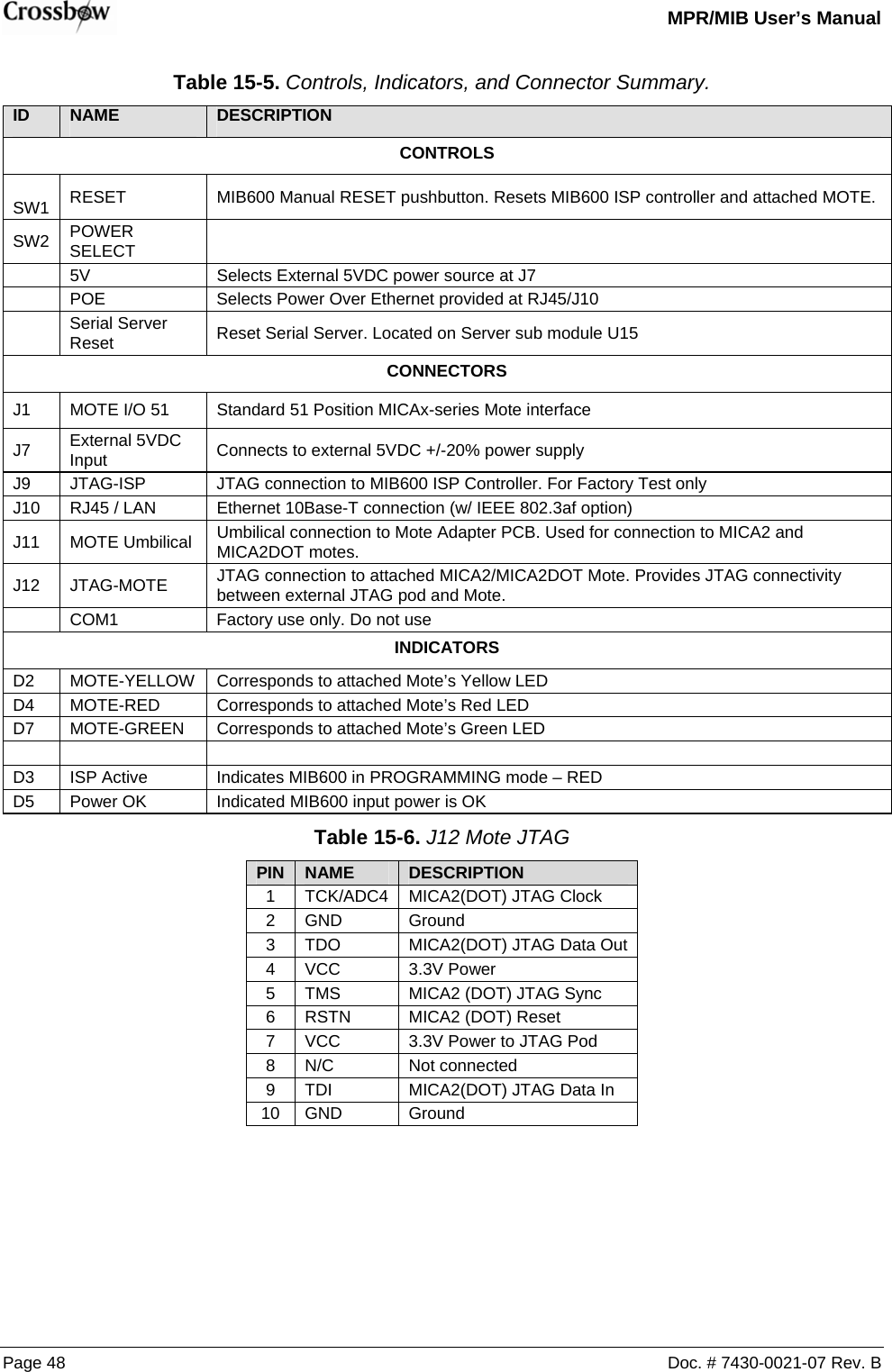
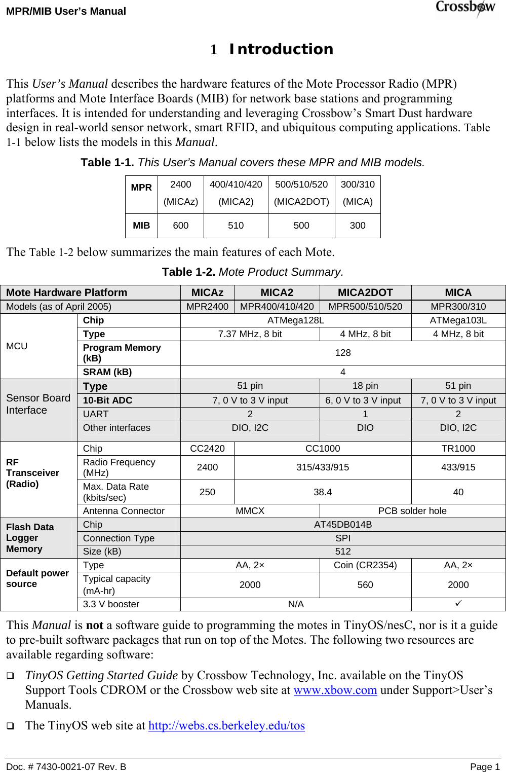
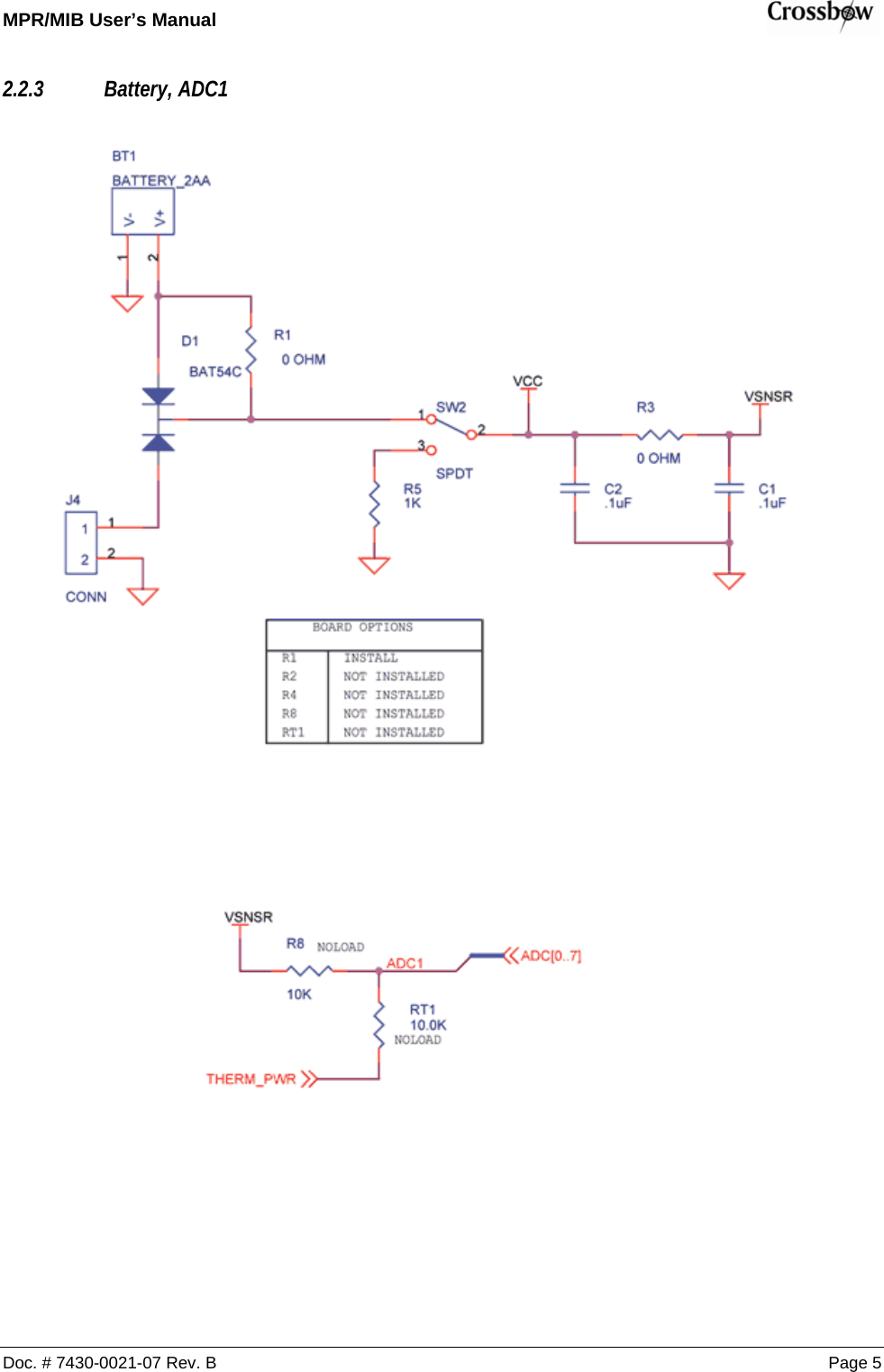
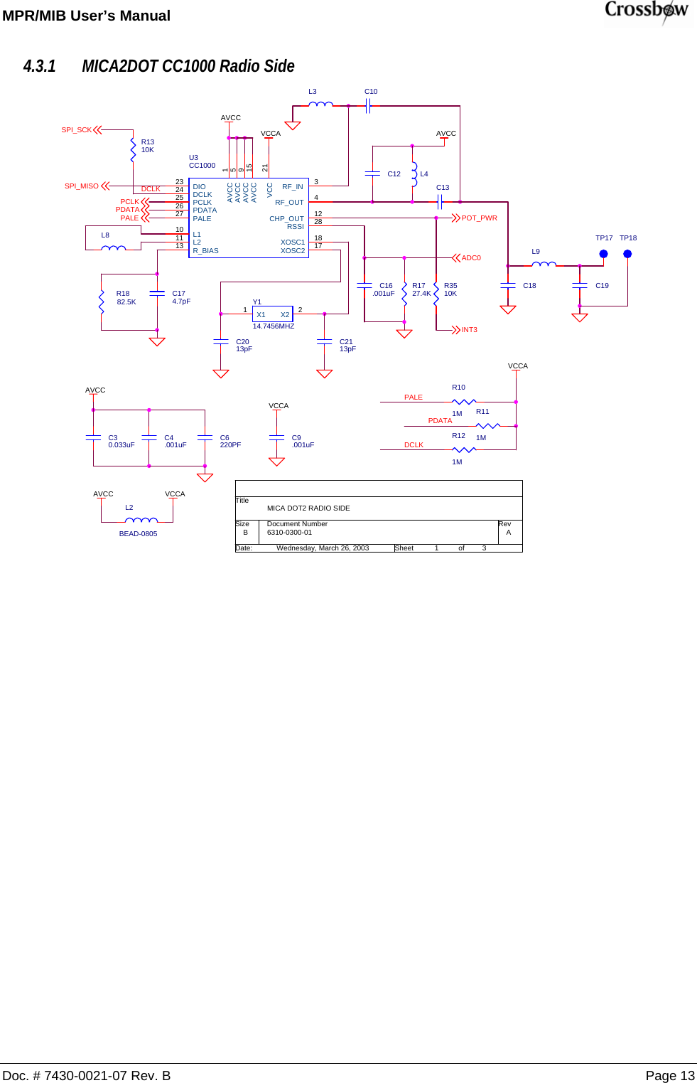
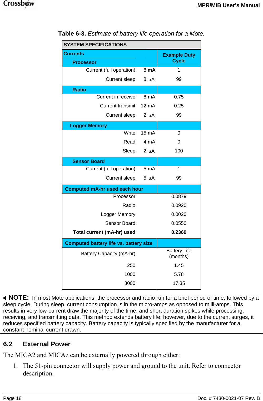
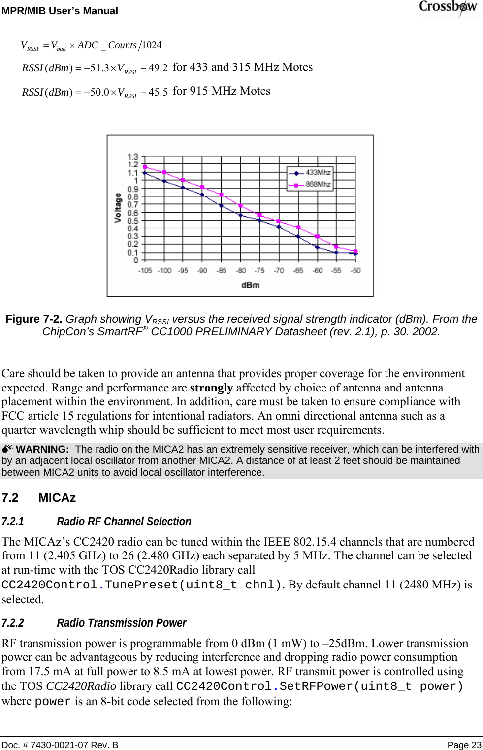
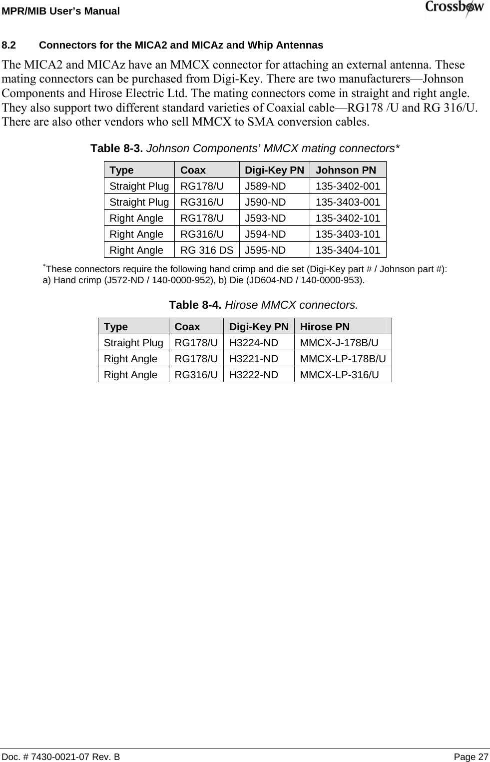
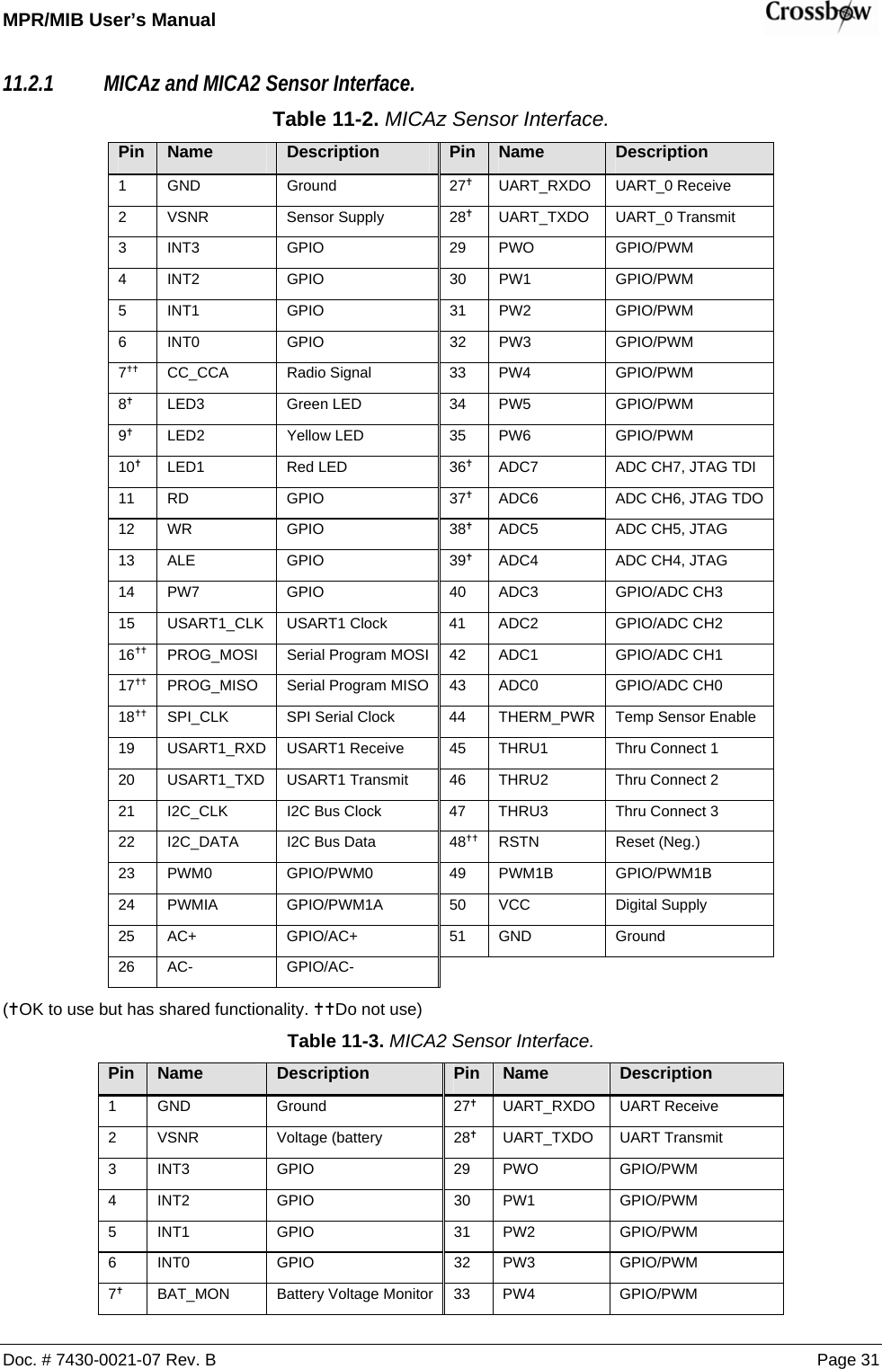
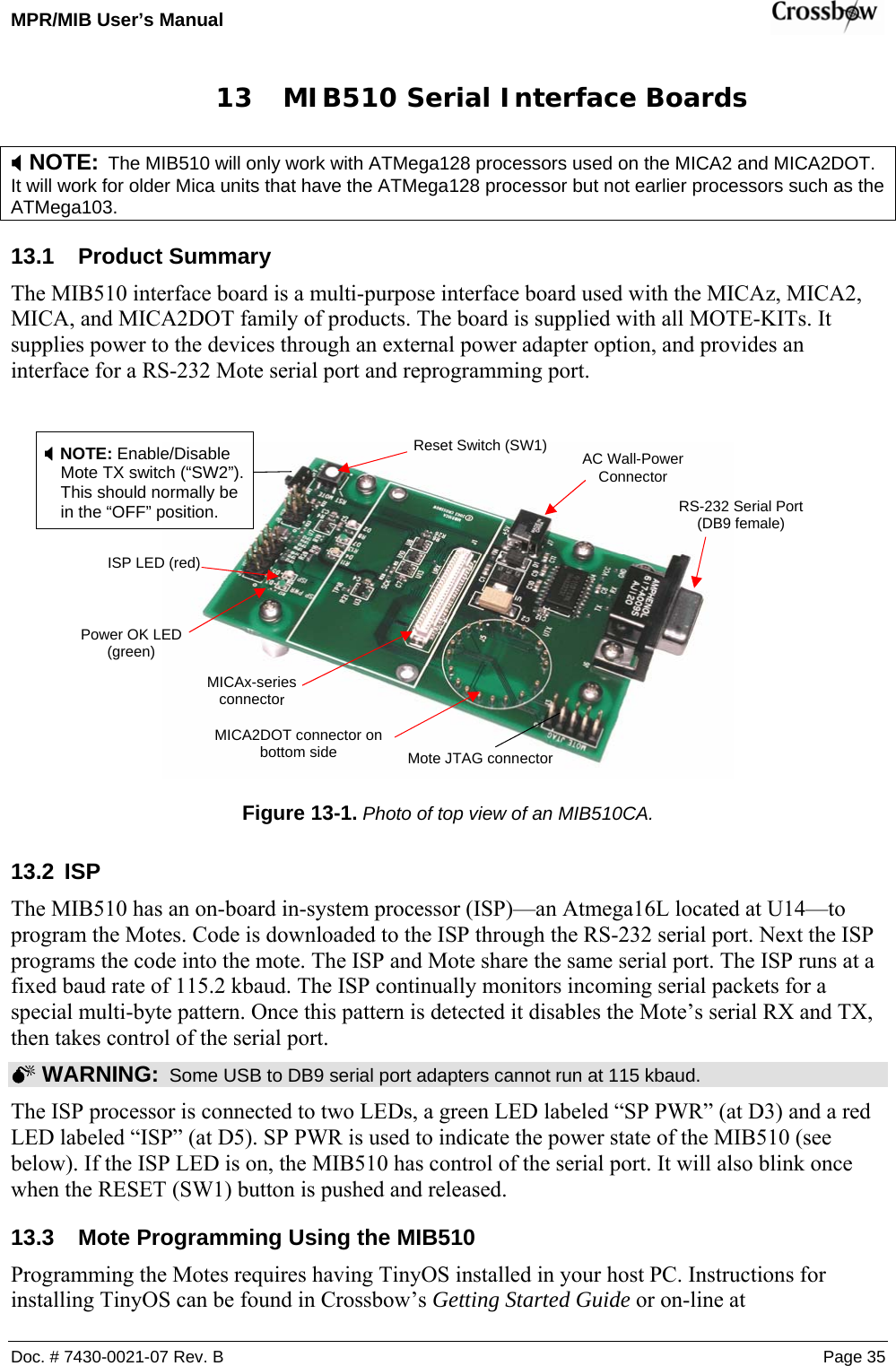
![MPR/MIB User’s Manual Page 8 Doc. # 7430-0021-07 Rev. B 3.2.3 51-pin Expansion Connector: Location J21 ADC4AC+SPI_SCKUART_RXD0USART1_RXDDESCRIPTIONADC3PW2ALEPWM1AADC2BAT_MONGNDVSNSRINT3INT2INT1INT0BAT_MONLED3LED2LED1RDWRALEPW7USART1_CLKPROG_MOSIPROG_MISOSPI_SCKUSART1_RXDUSART1_TXDI2C_CLKI2C_DATAPWM0PWM1AAC+AC-NAMEADC7PW5INT1ADC1PINTHRU3LED3LED1ADC[0..7]I2C_CLKPWM1BAC-PWM0 RSTNUART_TXD0RDINT2ADC5INT3THERM_PWRPW4UART_RXD0THRU1USART1_CLKPROG_MISOADC6PW1T[0..3]1234567891011121314151617181920212223242526VCCHIROSE PLUGJ21DF9-51P-1V(54)123456789101112131415161718192021222324252627282930313233343536373839404142434445464748495051WRPROG_MOSITHRU2LED2PW0PW6ADC0VSNSRI2C_DATAPW7INT0 PW3UART_TXD0USART1_TXDGROUNDSENSOR SUPPLYGPIOGPIOGPIOGPIOBATTERY VOLTAGE MONITOR ENABLELED3LED2LED1GPIOGPIOGPIOPOWER CONTROL 7USART1 CLOCKSERIAL PROGRAM MOSISERIAL PROGRAM MISOSPI SERIAL CLOCKUSART1 RX DATAUSART1 TX DATAI2C BUS CLOCKI2C BUS DATAGPIO/PWM0GPIO/PWM1AGPIO/AC+GPIO/AC-PW[0..7] 3.2.4 51-pin Expansion Pads: Location J22 THRU1PW4AC+ALETHRU2PROG_MISOUART_TXD0PWM0I2C_DATAADC[0..7]PW1PW[0..7]I2C_CLKADC6THRU3PW2USART1_RXDSPI_SCKBAT_MON6310-0306-01 AMICA2 MPR410CB-433MHZCROSSBOW TECHNOLOGY. INC.B46Friday, March 21, 2003TitleSize Document Number RevDate: Sheet ofPW6INT0UART_RXD0UART_TXD0PW0PW1PW2PW3PW4PW5PW6ADC7ADC6ADC5ADC4ADC3ADC2ADC1ADC0THERM_PWRTHRU1THRU2THRU3RSTNPWM1BVCCGNDADC5PWM1BAC-ADC3PWM1AINT1LED1ADC0USART1_CLK ADC1THERM_PWRNAME DESCRIPTIONADC7USART1_TXDM20MTG12811VSNSRINT3PROG_MOSIADC4HIROSE SOCKETJ22DF9B-51S-1V123456789101112131415161718192021222324252627282930313233343536373839404142434445464748495051M18MTG12811INT[0..3]WRPW3RSTNPW7UART_0 RECEIVEUART_0 TRANSMITPOWER CONTROL 0POWER CONTROL 1POWER CONTROL 2POWER CONTROL 3POWER CONTROL 4POWER CONTROL 5POWER CONTROL 6ADC INPUT 7 - BATTERY MONITOR/JTAG TDIADC INPUT 6 / JTAG TDOADC INPUT 5 / JTAG TMSADC INPUT 4 / JTAG TCKADC INPUT 3ADC INPUT 2ADC INPUT 1ADC INPUT 0 / RSSI MONITORTEMP SENSOR ENABLETHRU CONNECT 1THRU CONNECT 2THRU CONNECT3RESET (NEG)GPIO/PWM1BDIGITAL SUPPLYGROUNDLED2VCCUART_RXD0PINPW5PW0ADC2INT2LED3RD27282930313233343536373839404142434445464748495051](https://usermanual.wiki/Crossbow-Technology/003BU2400.Users-Manual-1/User-Guide-716628-Page-14.png)
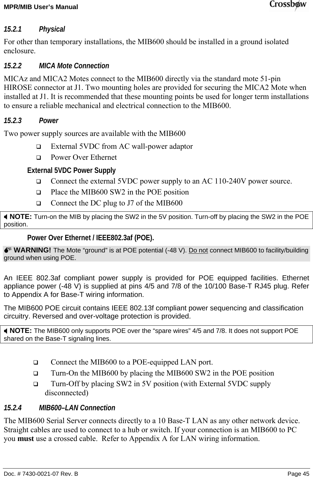
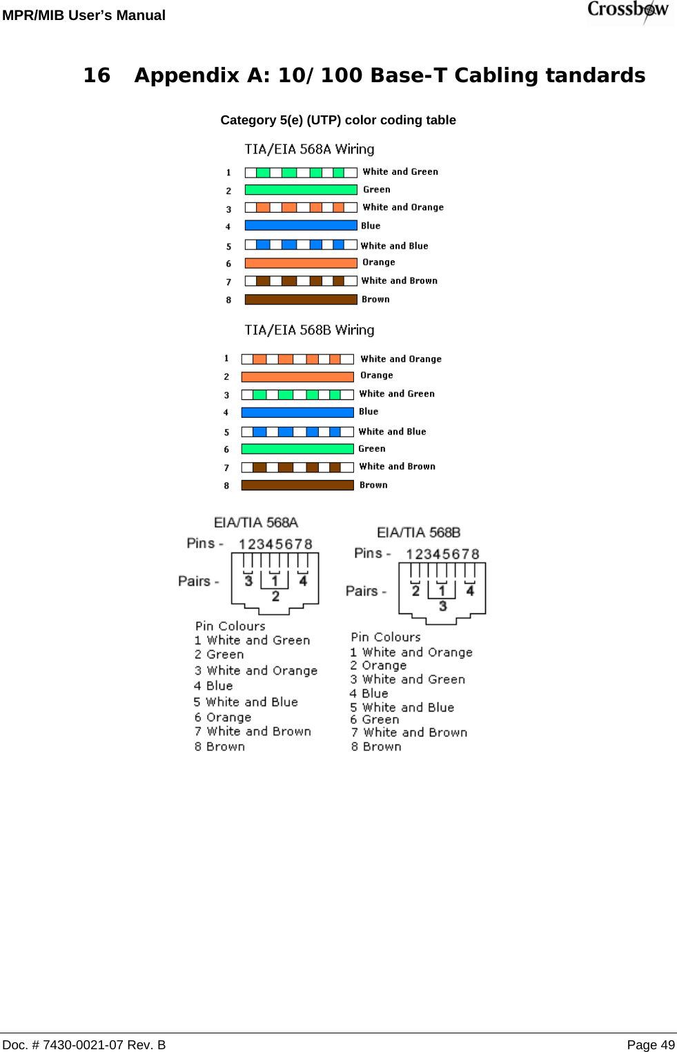
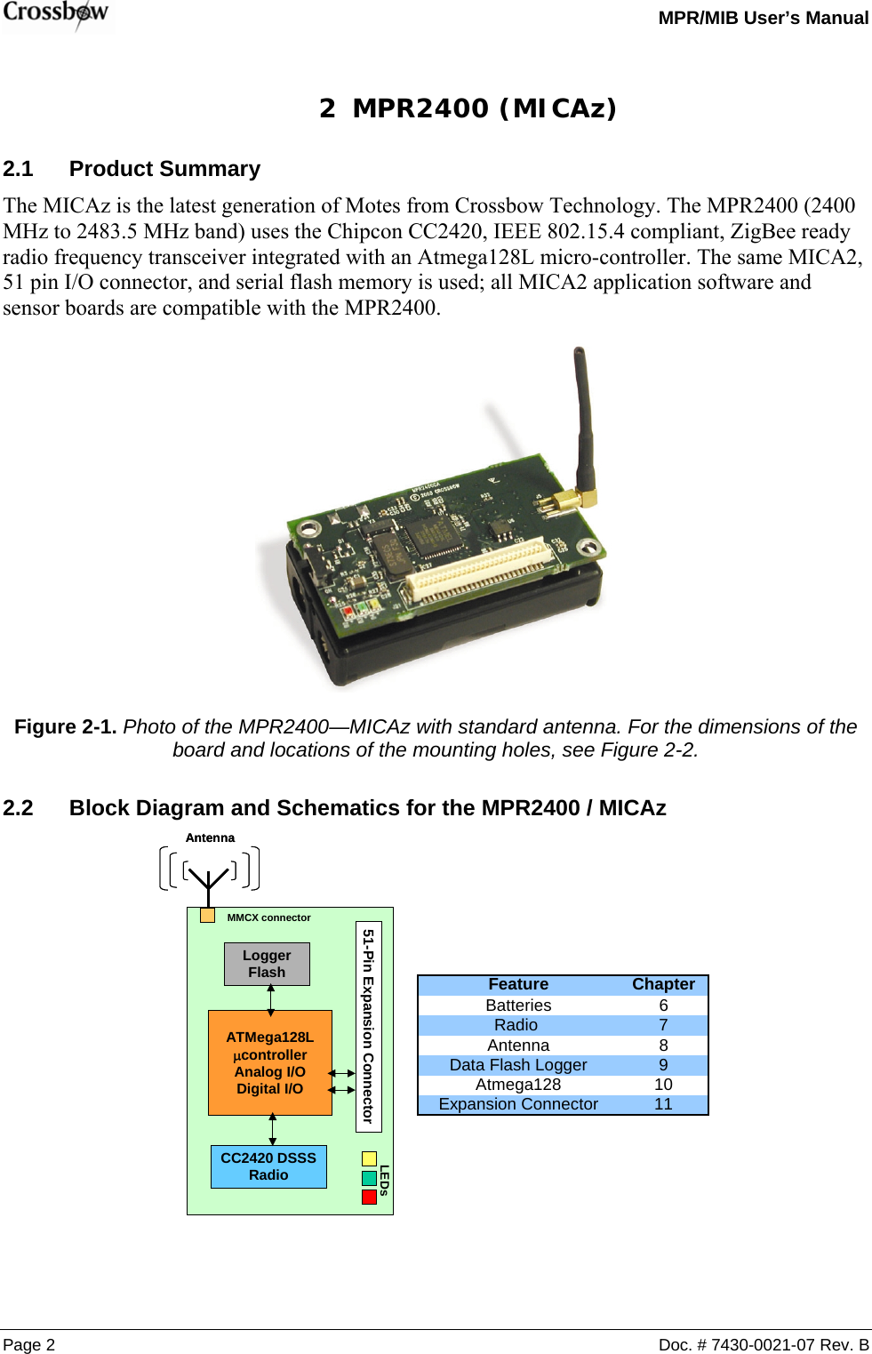
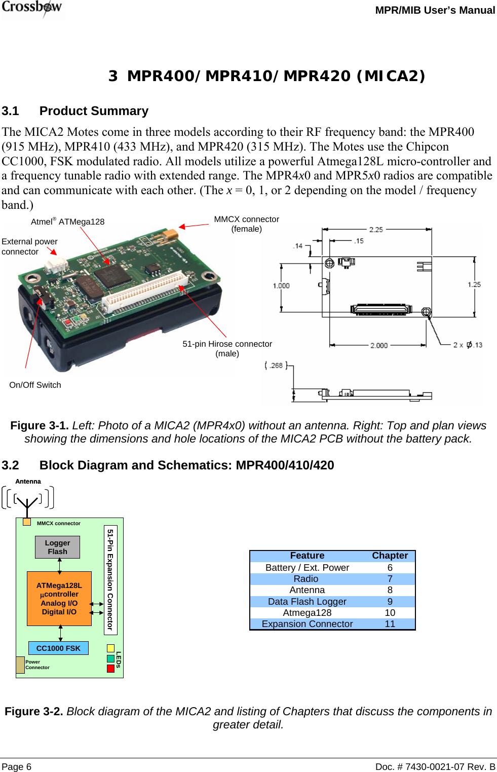
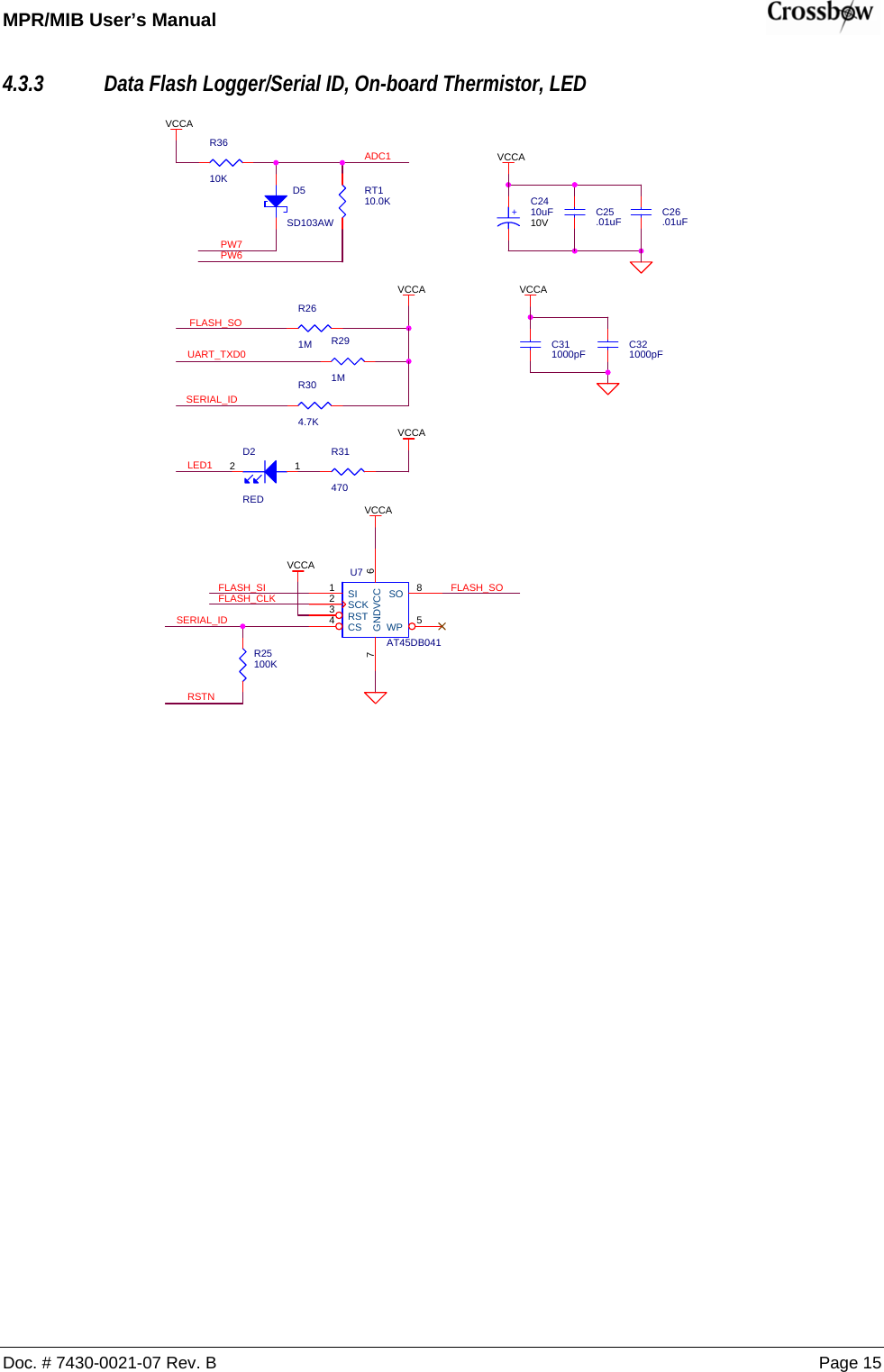
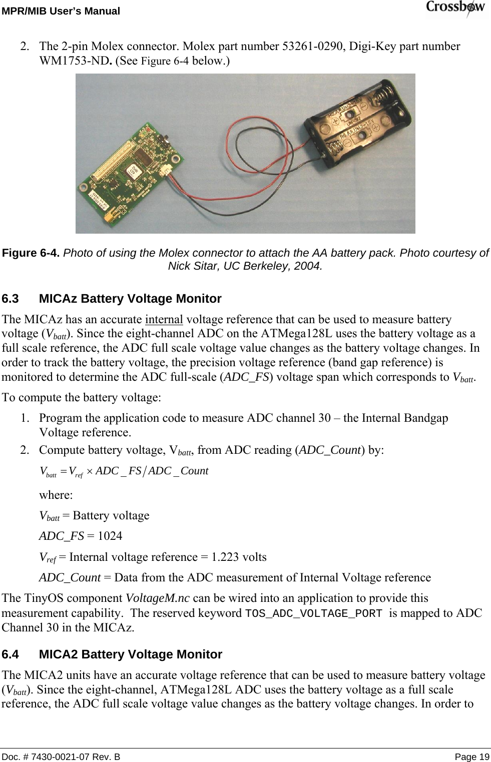
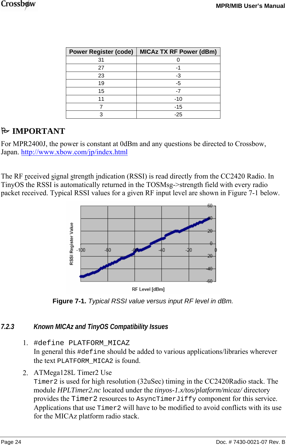
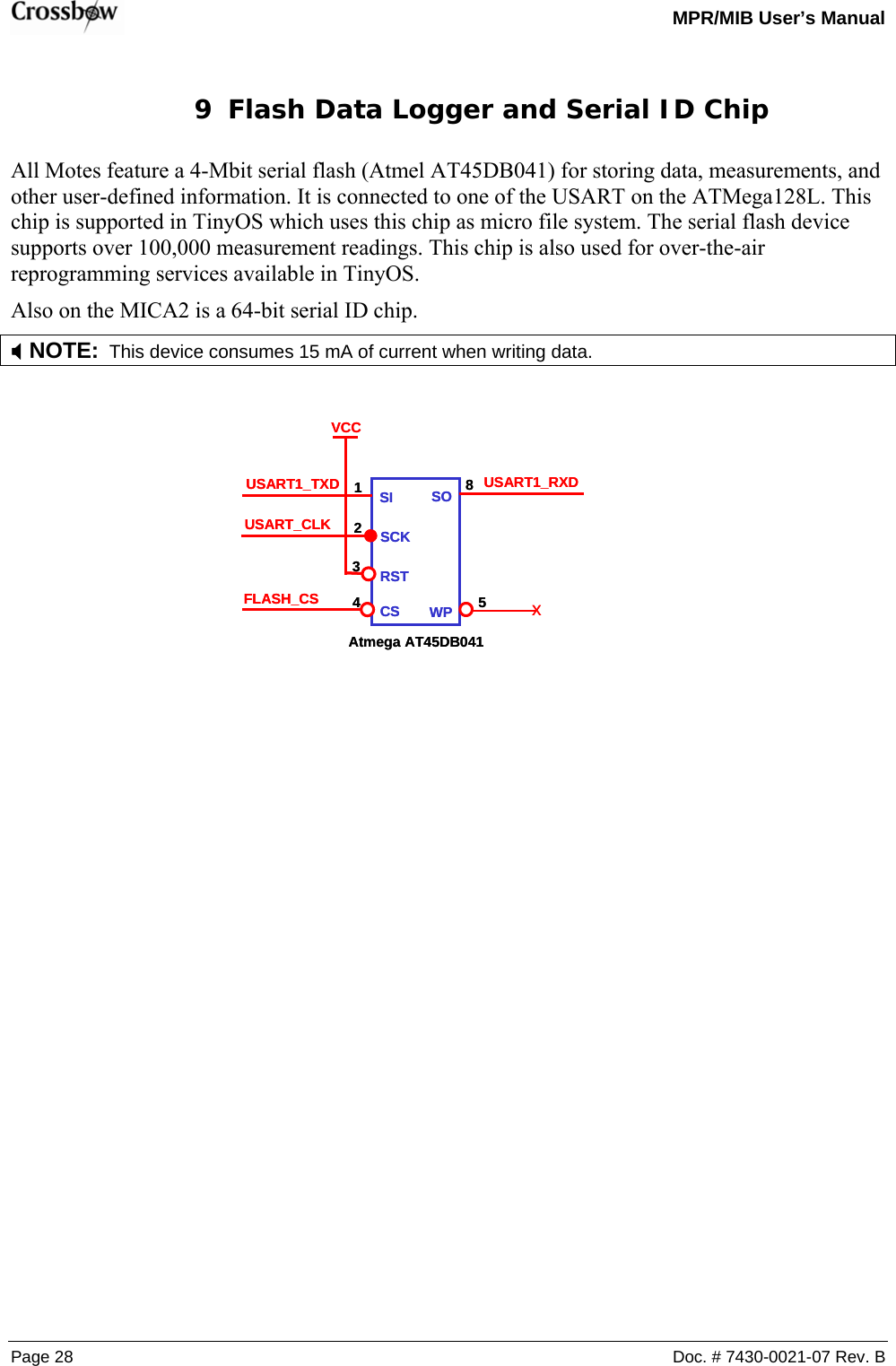
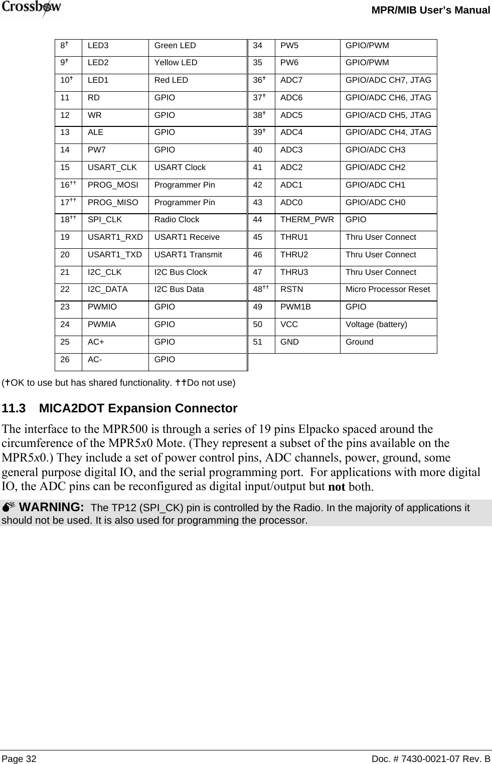
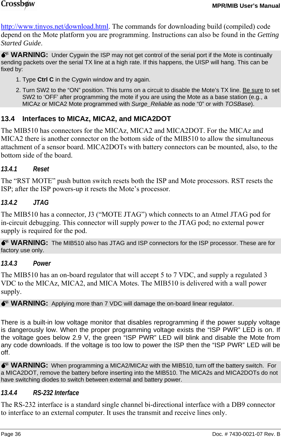
![MPR/MIB User’s Manual Doc. # 7430-0021-07 Rev. B Page 9 3.2.5 ATMega128L VCCBAT_MONC23.1uFSPI_MISOINT0PW6RDINT3ADC7PWM1AC3613pFR2010KVSNSRADC5LED3PW0Y332.768KHZ43 21X2GND GNDX1UART_TXD0I2C_CLKLED1AC+PW5R1610KPW3C22.1uFU7ATMEGA128L5150494847464544101112131415161735363738394041422526272829303132234567896160595857565554646212024233334431819PA0/AD0PA1/AD1PA2/AD2PA3/AD3PA4/AD4PA5/AD5PA6/AD6PA7/AD7PB0/SSPB1/SCKPB2/MOSIPB3/MISOPB4/OC0PB5/OC1APB6/OC1BPB7/OC1CPC0/A8PC1/A9PC2/A10PC3/A11PC4/A12PC5/A13PC6/A14PC7/A15PD0/I2C_CLKPD1/I2C_DATAPD2/RXD1PD3/TXD1PD4/IC1PD5/XCK1PD6/T1PD7/T2PE0/RXD0PE1/TXD0PE2/XCK0PE3/OC3APE4/OC3BPE5/OC3CPE6/T3PE7/IC3PF0/ADC0PF1/ADC1PF2/ADC2PF3/ADC3PF4/TCKPF5/TMSPF6/TDOPF7/TDIAVCCAREFPENRSTXTAL1XTAL2PG0/WRPG1/RDPG2/ALEPG3/TOSC2PG4/TOSC1USART1_CLKC21.1uFFLASH_CSWRSPI_SCK ADC2ADC3R2110KPW1CHP_OUTTHERM_PWRPWM1BRSTNADC4VCCPALEAC-INT2LED2ADC1PWM0USART1_RXDPW4R180 OHMSERIAL_IDR15470UART_RXD0INT[0..3]C3513pFI2C_DATAPW[0..7]6310-0306-01 AMICA2 MPR410CB-433MHZCROSSBOW TECHNOLOGY. INC.B56Friday, March 21, 2003TitleSize Document Number RevDate: Sheet ofADC0ADC6ALEPDATAPCLKY27.3728MHZ2341X2X2X1X1PW7ADC[0..7]SPI_MOSIUSART1_TXDPW2INT1](https://usermanual.wiki/Crossbow-Technology/003BU2400.Users-Manual-1/User-Guide-716628-Page-15.png)
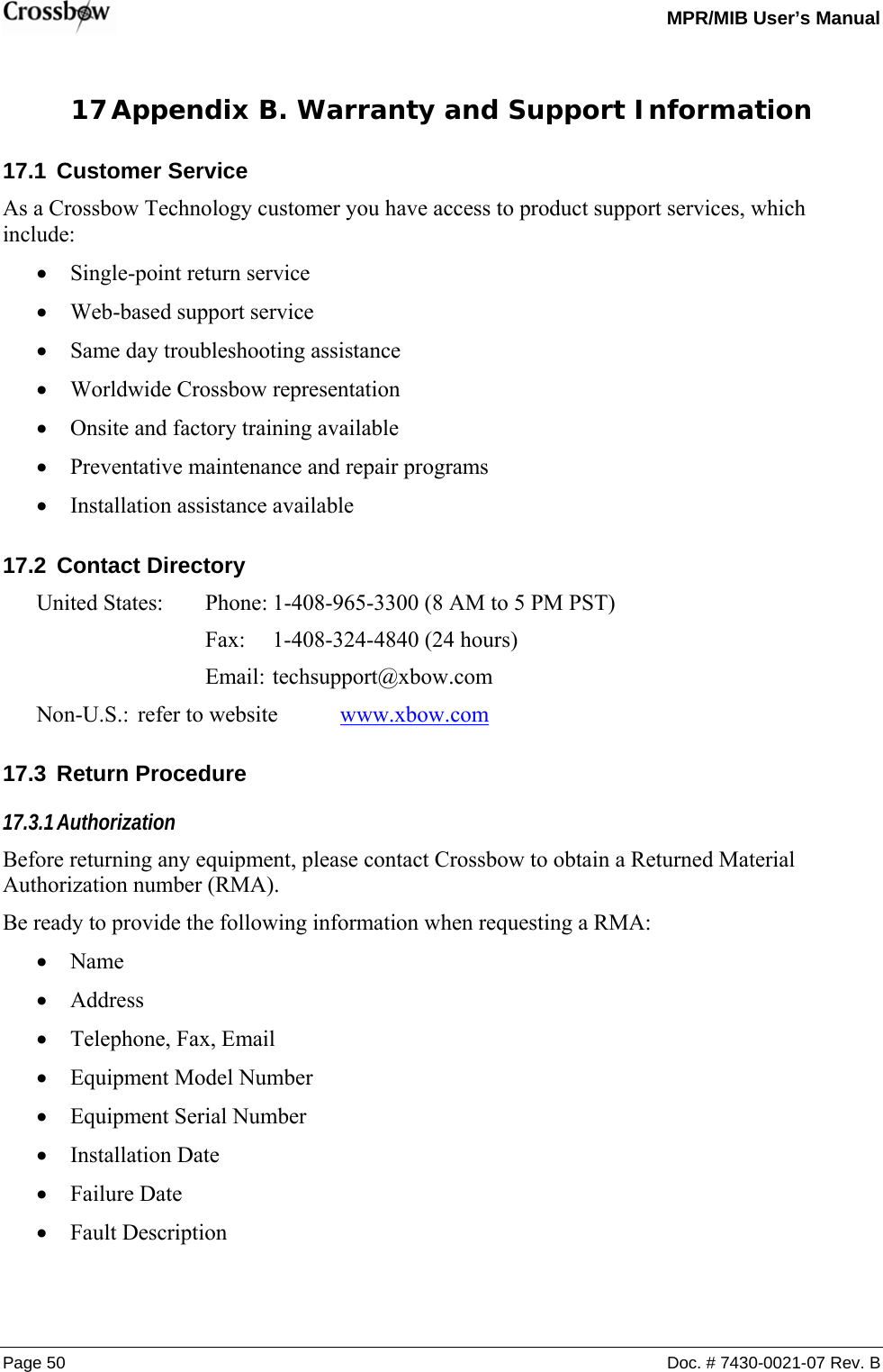
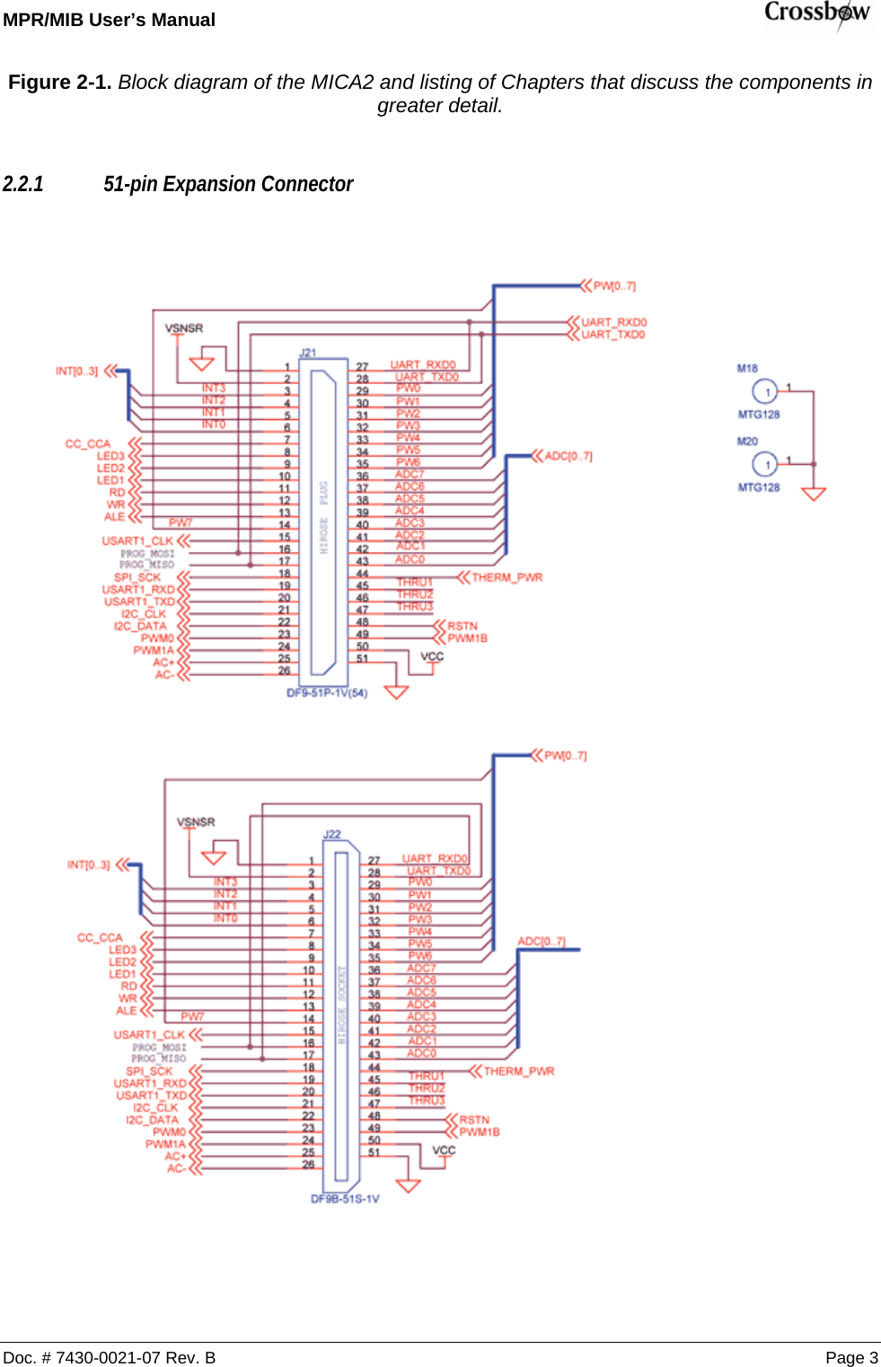
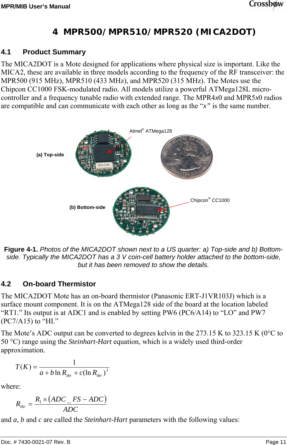
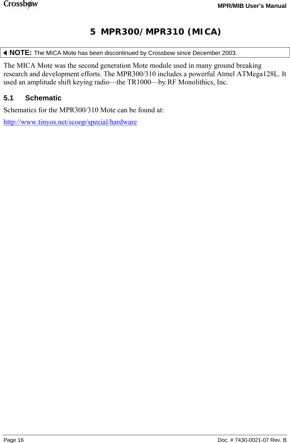
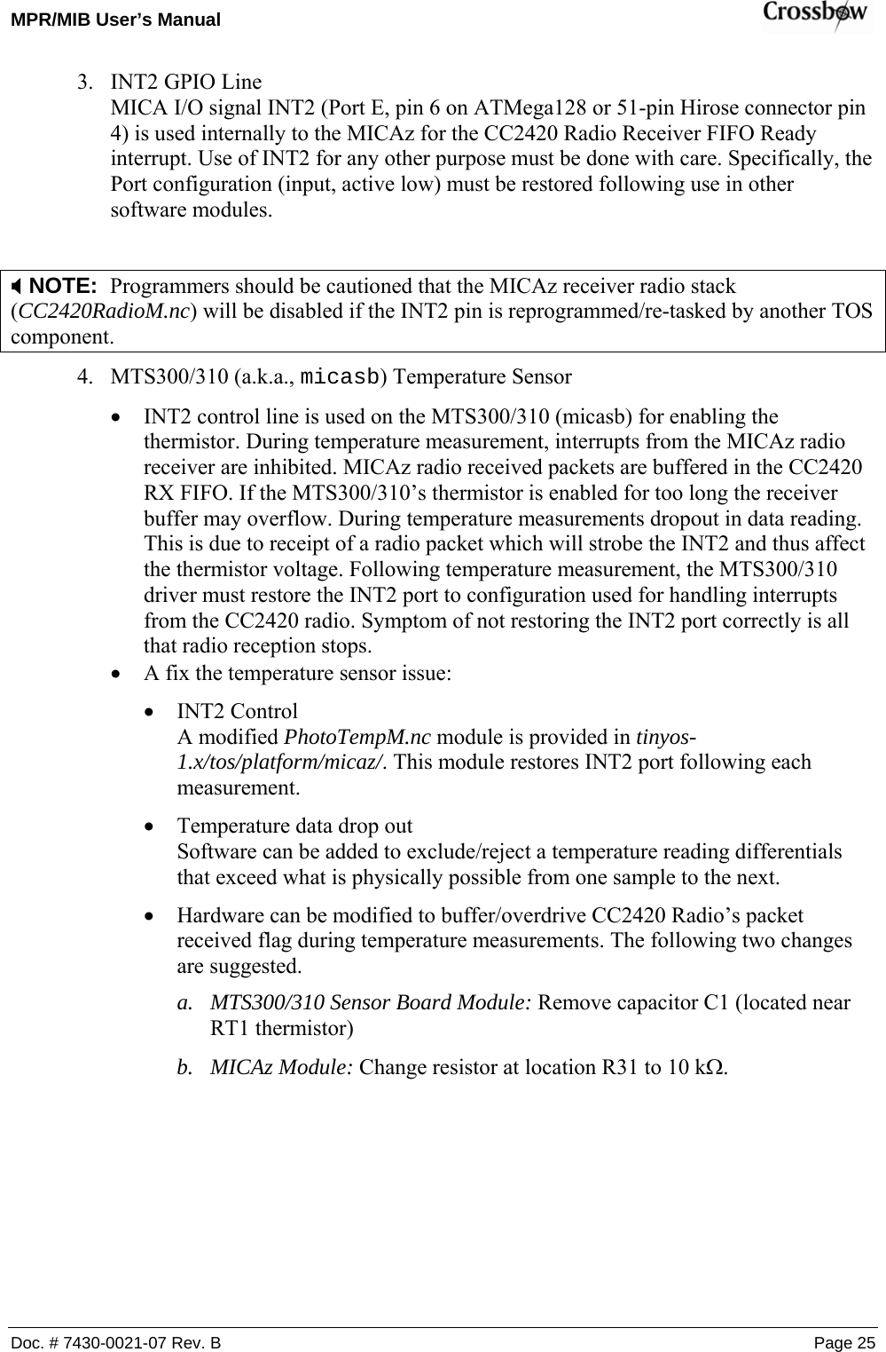
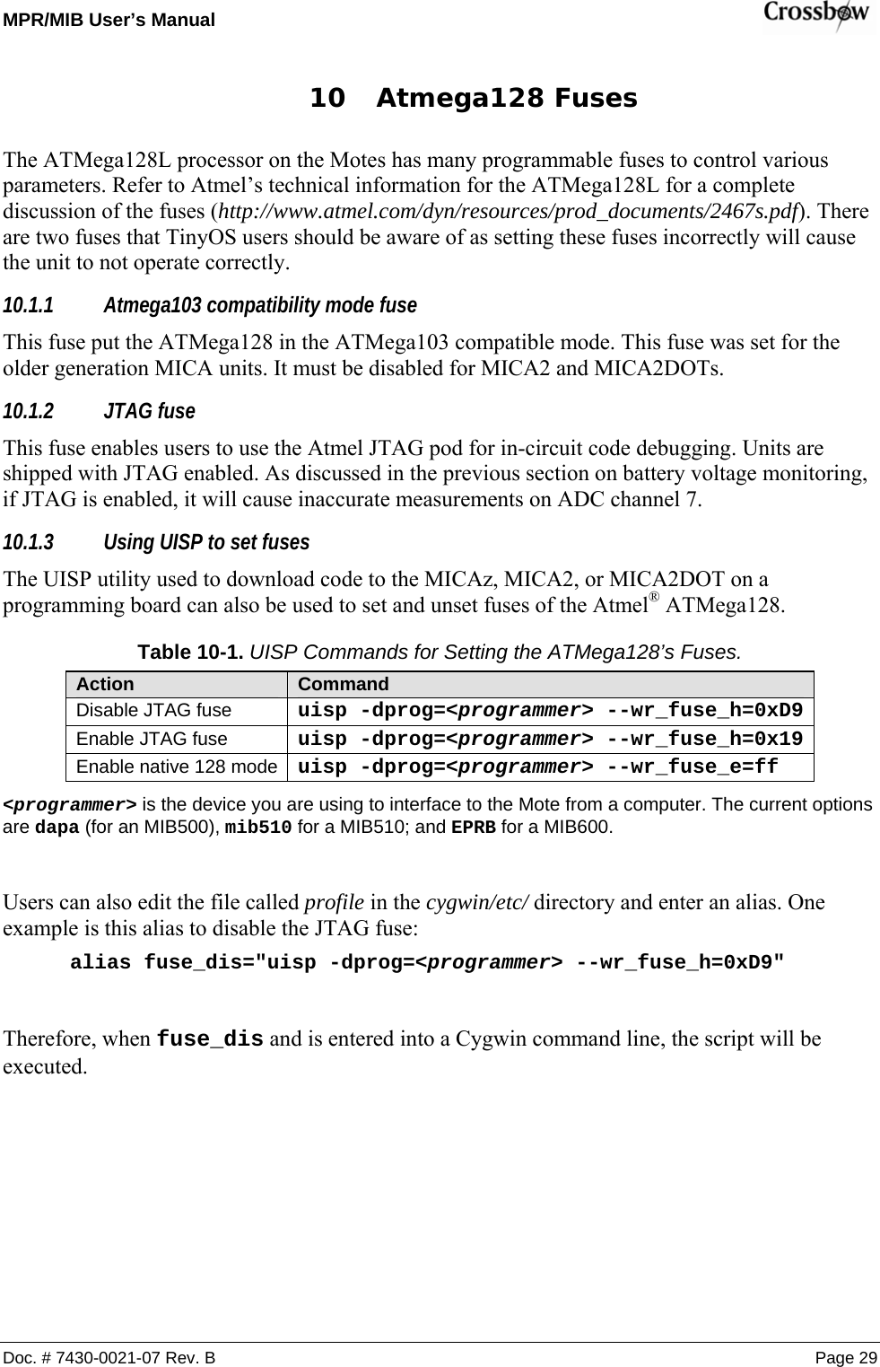
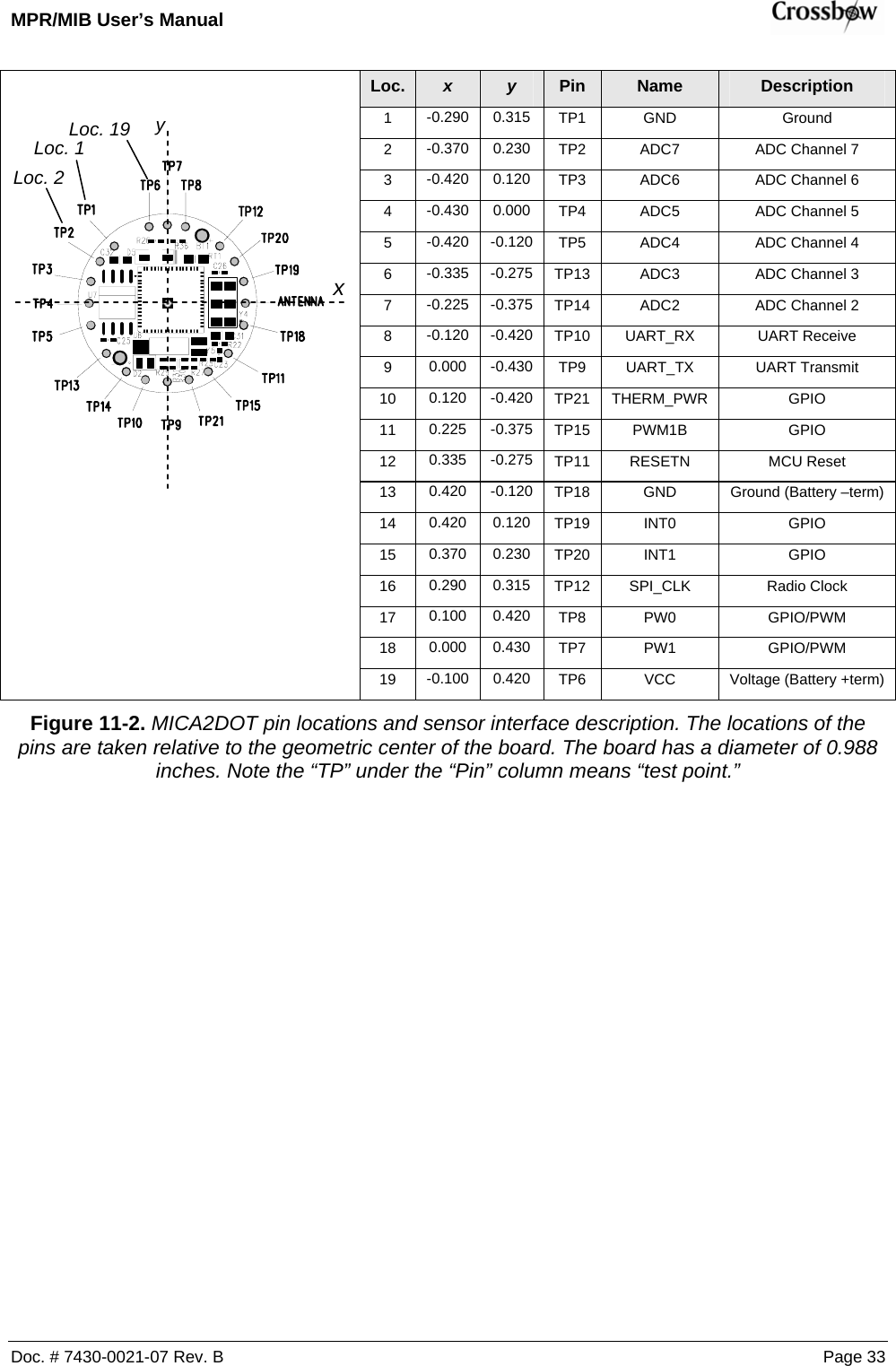
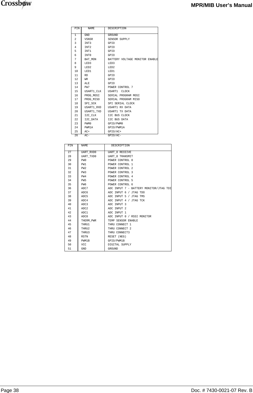
![MPR/MIB User’s Manual Page 10 Doc. # 7430-0021-07 Rev. B 3.2.6 Flash Memory, Serial ID, LEDs, USART SERIAL_IDVCCPCLKPDATAPALED2RED126310-0306-01 AMICA2 MPR410CB-433MHZCROSSBOW TECHNOLOGY. INC.B66Friday, March 21, 2003TitleSize Document Number RevDate: Sheet ofC27.01uFFLASH INTERFACEUSART1_CLKC28.01uFRADIO CONTROLC321000pFR234.7KVCCC30.01uFUSART1_TXDU5AT45DB0411234 58SISCKRSTCS WPSOUART INTERFACEUART_RXD0UART_TXD0CONTROL INTERFACER191MLED2U6DS2401P2DQD4YELLOW12USART1_RXD+C2410uF10VR27470I2C_CLKI2C_DATASPI_SCKSPI_MOSISPI_MISOCHP_OUTADC0(RSSI)RADIO DATALED1ADC7C29.01uFC25.01uFR25470R221MVCCC331000pFLED3FLASH_CSFLASH_CSVCCD3GREEN12FLASH_SIFLASH_SOFLASH_CLKSERIAL_IDSENSOR INTERFACER26470PW[0..7]ADC[1..6]USART1_RXDVCCVCC MONITORUART_TXD0C311000pF C341000pFC26.01uF](https://usermanual.wiki/Crossbow-Technology/003BU2400.Users-Manual-1/User-Guide-716628-Page-16.png)
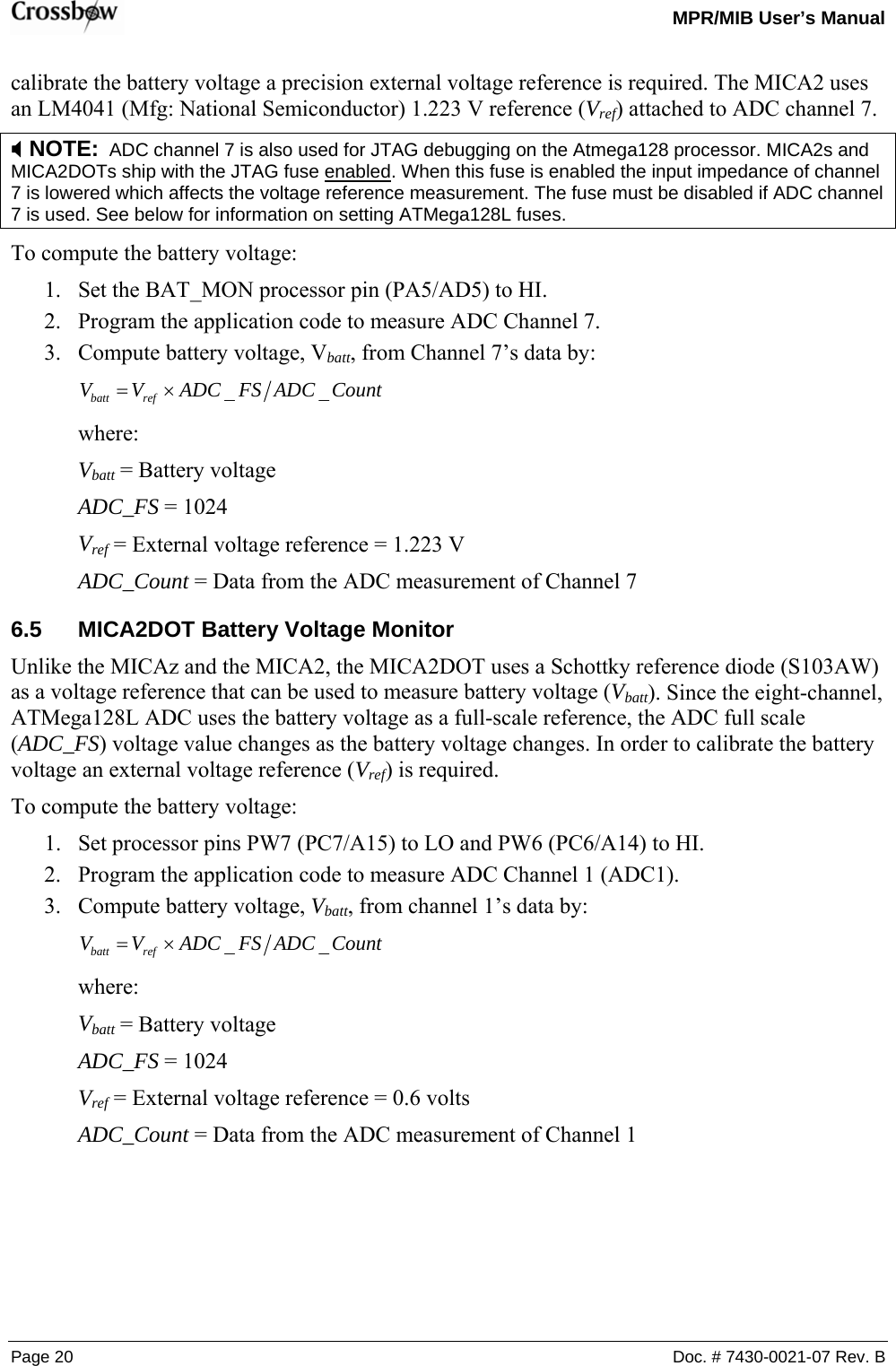
![MPR/MIB User’s Manual Page 14 Doc. # 7430-0021-07 Rev. B 4.3.2 MIC2DOT ATMega128L, ADC Interfaces, Battery PW5Y532.768KHZ321NCX2X1SPI_MOSIINT0SPI_SCKPDATAVCCAR2210KPWM1BPW[0..7]R21470ADC1POT_PWRLED2UART_RXD0INT1ALEADC6ADC5AC+LED3VCCADC_BOOST_SHDNPW7PWM0SERIAL_IDSPI_MISOADC3PWM1AINT2Y44.000MHZ65213 4X1GNDGNDX1X2 X2PW2ADC4RSTNU6ATMEGA128LMLF21522253635150494847464544101112131415161735363738394041422526272829303132234567896160595857565554646212024233334431819VCCVCCGNDGNDGNDPA0/AD0PA1/AD1PA2/AD2PA3/AD3PA4/AD4PA5/AD5PA6/AD6PA7/AD7PB0/SSPB1/SCKPB2/MOSIPB3/MISOPB4/OC0PB5/OC1APB6/OC1BPB7/OC1CPC0/A8PC1/A9PC2/A10PC3/A11PC4/A12PC5/A13PC6/A14PC7/A15PD0/INT0PD1/INT1PD2/RXD1PD3/TXD1PD4/IC1PD5/XCK1PD6/T1PD7/T2PE0/RXD0PE1/TXD0PE2/XCK0PE3/OC3APE4/OC3BPE5/OC3CPE6/T3PE7/IC3PF0/ADC0PF1/ADC1PF2/ADC2PF3/ADC3PF4/TCKPF5/TMSPF6/TDOPF7/TDIAVCCAREFPENRSTXTAL1XTAL2PG0/WRPG1/RDPG2/ALEPG3/TOSC2PG4/TOSC1ADC7C23.1uFR2810KPALEADC2GPS_ENAC22.1uFPW3 AC-PCLKLED1PW6RDVCCAPW0ADC[0..7]SPI_MOSII2C1_DATAFLASH_SIFLASH_SOR2710KPW1ADC0FLASH_CLKUART_TXD0PW4I2C1_CLKWRINT3 INT0TP8TP19ADC[0..7]TP10TP7PW1SPI_SCKRSTNADC3TP6 TP11TP13PW0TP20ADC5TP4VCCAADC2PWM1BTP15BT1BATTERY1 2TP2VCCATP9TP1ADC7ADC6TP21GPS_ENAPW[0..7]ADC4TP5TP3 TP12TP14INT1UART_TXD0UART_RXD0](https://usermanual.wiki/Crossbow-Technology/003BU2400.Users-Manual-1/User-Guide-716628-Page-20.png)
![MPR/MIB User’s Manual Doc. # 7430-0021-07 Rev. B Page 21 7 Radios 7.1 MICA2 and MICA2DOT 7.1.1 Radio Considerations The radio on the MICA2 and MICA2DOT is capable of multiple channel operation, within the intended band of operation. The MPR420/MPR520 can span up to 4 channels of operation in the 315 MHz band, the MPR410/MPR510 can span up to 4 channels of operation in the 433 MHz band (433.05–434.79 MHz). The MPR400/MPR500 can operate in two frequency regions: 868–870 MHz (up to 4 channels) and 902–928 MHz (up to 54 channels). The actual number of possible channels is higher for all the MICA2/MICA2DOT motes. However, it is recommended that the adjacent channel spacing should be at least 500 kHz to avoid adjacent channel interference thereby reducing the number of available channels. A tutorial on how to change frequency is available at http://www.tinyos.net/tinyos-1.x/doc/mica2radio/CC1000.html. 7.1.2 Radio Transmission Power The radio on the MICA2/MICA2DOT can be adjusted for a range of output power levels. The register in the radio that controls the RF power level is designated PA_POW at address 0x0B, and the values and their corresponding RF outputs are provided on Error! Reference source not found. below. It shows the closest programmable value for output powers in steps of 1 dBm. For power down mode the Chipcon datasheet says, “the PA_POW should be set to 00h [0x00] for minimum leakage current.”](https://usermanual.wiki/Crossbow-Technology/003BU2400.Users-Manual-1/User-Guide-716628-Page-27.png)
![MPR/MIB User’s Manual Doc. # 7430-0021-07 Rev. B Page 37 13.4.5 Schematics HIROSE SOCKETJ1DF9B-51S-1V123456789101112131415161718192021222324252627282930313233343536373839404142434445464748495051PROG_MISOADC4INT0PW2PW7PW1ADC4PROG_MOSIINT0USART1_RXDPW[0..7]INT2AC+VCCTHERM_PWRVSNSRPWM0VCCPW5M1MTG12811ADC[0..7]INT3PWM1BAC+LED1THRU1USART1_TXDLED3ALEPW1VSNSRAC-ADC6USART1_CLKAC-PWM1BHIROSE PLUGJ2DF9-51P-1V(54)123456789101112131415161718192021222324252627282930313233343536373839404142434445464748495051ADC5USART1_RXD THRU2PROG_MISOLED2PW3PW6WRADC3RSTNPROG_MOSIINT[0..3]THERM_PWRPW7PWM0THRU2INT[0..3]INT2ADC2UART_TXD0PW0THRU3LED3INT1BAT_MONADC7PW4PW5THRU3ADC1LED1USART1_CLKI2C_CLKADC3I2C_DATAI2C_CLKPWM1AADC1UART_RXD0ADC0UART_RXD0PW[0..7]INT1PW3SPI_SCKUART_RXD0ADC7ADC5BAT_MONLED2RDI2C_DATASPI_SCKUART_TXD0RDALEPW0INT3PWM1AUART_TXD0THRU1RSTNUSART1_TXDADC[0..7]PW2PW4PW6ADC6ADC0 M2MTG12811ADC2WR](https://usermanual.wiki/Crossbow-Technology/003BU2400.Users-Manual-1/User-Guide-716628-Page-43.png)
![MPR/MIB User’s Manual Doc. # 7430-0021-07 Rev. B Page 39 13.4.6 RS-232, MICA2DOT, and Ext. Power Interface. M4MTG12811LPT1_MISOJ4DB25-M-RA 5 174 163 152 141 207 196 1810229 218 231124122513ADC5VCCINT1J3HDR2X5 1 2 3 4 5 6 7 8 910 VCCADC[0..7]RSTNRS232_TX M6MTG12811C1 .1uF50VTHERM_PWRADC6RSTNRS232_RX TP6J6DB9-F-RA5 9 4 8 3 7 2 6 1 SPI_SCKADC6INT0TP5PWM1BTP7PIN OUTER J7PJ-014D2 3 1 UART_TXD0U1 LMS8117-3.3 3 1 24VINADJVOUTGND PW1M3 MTG128 1 1 D1 B2100+C210uF35VTDI TP9TCK TDO TMS PW0J5DOT21234567891011121314151617181912345678910111213141516171819ADC4ADC26310-0304-01 AMIB500CA MICA PROG BOARD CROSSBOW TECHNOLOGY. INC. B23Wednesday, March 26, 2003TitleSize Document NumberRevDate: Sheet ofLPT1_MOSIADC3ADC4VCCLPT1_RSTUART_RXD0TP8ADC7ADC7M5 MTG128 1 1 ADC5LPT1_SCK](https://usermanual.wiki/Crossbow-Technology/003BU2400.Users-Manual-1/User-Guide-716628-Page-45.png)
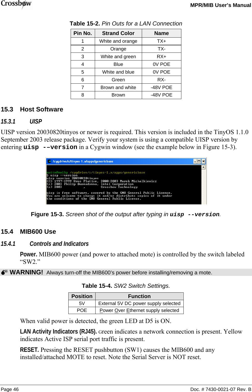
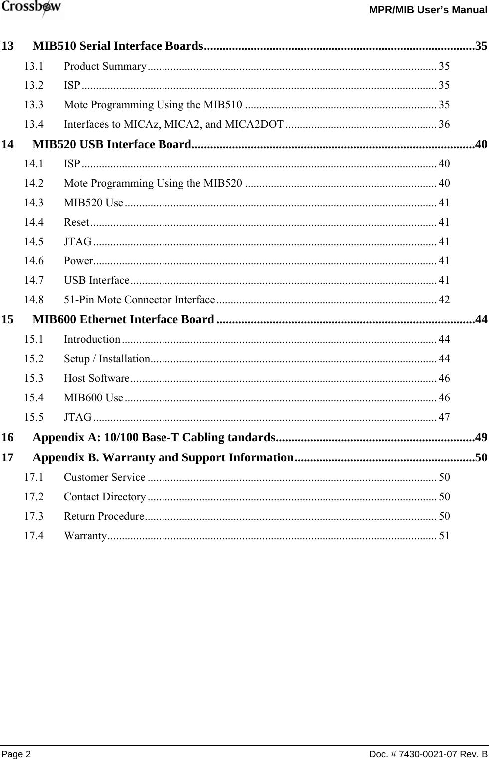
![MPR/MIB User’s Manual Page 42 Doc. # 7430-0021-07 Rev. B DPTP6VINDMTP5J51 USB-A123456TP7 TP7DMDPTP5J51A-USB-A-LP/SMT123456VINTP6 MIB520CA MIB520CB Table 14-3. Pin Outs for a USB Connection Pin No. Name Description 1 VBUS Powered Supply Pin 2 USBDM USB Data Signal Minus 3 USBDP USB Data Signal Plus 4 GND Ground Supply Pin 14.8 51-Pin Mote Connector Interface PW7PWM1ALED2THRU2PW6USART1_CLKUART_RXD0VCCLED3PW0PW1I2C_CLKPW5ADC7AC-INT3AC+RSTNINT1ALETHERM_PWRINT0PWM0ADC5HIROSE SOCKETJ1DF9B-51S-1V123456789101112131415161718192021222324252627282930313233343536373839404142434445464748495051RDVSNSRPW4WRUART_TXD0ADC3USART1_TXDPROG_MOSIPW2I2C_DATAADC6PROG_MISOUSART1_RXDLED1THRU3INT[0..3]ADC[0..7]SPI_SCKADC[0..7]PW3ADC4INT2UART_RXD0ADC0THRU1BAT_MONPWM1BPW[0..7]ADC1UART_TXD0ADC2](https://usermanual.wiki/Crossbow-Technology/003BU2400.Users-Manual-1/User-Guide-716628-Page-48.png)