Crossbow Technology 006SSM1000 Wireless Soil Monitoring Network User Manual usermanual
Crossbow Technology, Inc. Wireless Soil Monitoring Network usermanual
manual
- 1 -
RZ Wireless SSN (Crossbow SSM1000CB) Installation Instructions
RZ Wireless Soil Sensor Nodes are the crux of the RZ wireless soil monitoring system. The SSN
is a battery operated node that goes to sleep periodically to conserve energy. For the first two
hours after it is turned on it will wake up every 30 seconds (report rate), take measurements from
each of its 2 sensors (each sensor measures temperature, moisture and conductivity
simultaneously). It then transmits that information to a nearby CCN. After the SSN has been on
for 2 hours the report rate will change to every 10 minutes. The report rate can be managed using
the RZ Wireless Application (see the RZ Wireless User’s Guide for more information)
Note that the instruction for SSN installation requires knowledge of the soil type – sand,
silt or clay. The installer should verify the soil type with the Site superintendent before
installing SSNs. Soil types for each node is set using the RZ Wireless application
The step-by-step instructions for an SSN install include the following:
• Collect items needed for the install.
• Set SSN ID
• Install SSN
• Record SSN installation information
• Verify the SSN installation
- 2 -
1. Collect Items Needed for the Install
Steps:
a. Determine the hole(s) at which SSNs are to be installed.
b. Consult the site survey to determine the number of SSNs needed for the hole (plus 1 or 2
spares).
c. Consult the site survey to determine the depth for each sensor (upper and lower)
d. Collect needed SSNs and all other equipment, materials and tools as listed in Table 3.
e. Transport all items to the specified hole.
2. Setting SSN ID Numbers
The SSN IDs are set automatically by the network or by editing of the file joinmap.xtbl in the
same way as CCN IDs. In order to keep track of which SSN is installed at what location, it is
recommended that a logical scheme be employed to number these units. The network will
automatically increment the ID by 1 for each new Node that joins the network.
We recommend that the numbers 201-220 be reserved for CCNs. Sensor Nodes should be
numbered incrementally based on which holes they are installed on. Take the Hole number and
multiply by 10 then add 1 for each successive Node. E.g., on Hole #5 the first Sensor Node would
be 51, the second would be 52. For Hole 13, the first Sensor Node would by 131 and so on. Use
191-199 for the putting green and numbers less than 10 for the chipping green.
Note that the device whose ID is to change must be reset after changing the number in the
joinmap.xtbl file. So the Node must not be buried until the Node ID is set.
Steps:
a. Remove SSN from box and verify the (manufacturer’s) unique ID number on the SSN
matches that on the box.
b. Take a sensor node out of the box; turn it on by depressing the button on the side of the
unit, and listen for beeping sounds.
c. If sensor is working the unit will beep-out an assigned ID.
- 3 -
d. Record on the box and also enter the ID number into a log.
e. Edit the joinmap.xtbl file so that the SSN IDs match the numbering scheme for each hole
f. Note the new ID number on the box and the hole/location that it is detained for.
g. Restart the RZ wireless processes and restart the SSN. The new ID should be “beeped-out”.
h. The SSN is now ready to be installed.
3. Installing each SSN
Steps:
a. Using the site survey, confirm the specific SSN location with Site superintendent or
designee.
b. If the location is changed, redline site survey to indicate new location and note the reason
for change.
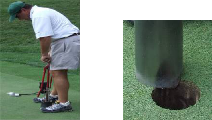
c. Cut two adjoining holes with a cup cutter as shown in pictures below.
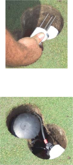
d. Install the SSN.
• For a Stevens sensor:
Install the 2 Sensor probes by “plugging” them in horizontally into the wall of one of
the freshly cut 4” cup holes where top 2 prongs are the number of inches below the
- 4 -
soil as specified for the grass type (2” and 4” for cool season grasses, 1” and 3” for
warm season grasses).
Position the radio node in the adjoining 4”-cup hole.
• For an AST sensor:
Position the radio node in one of the freshly cut 4” cup holes.
Install the 2 Sensor probes by “plugging” them into the wall of adjoining 4”-cup hole
in a vertical orientation (see diagram) where top edge of probe is the number of
inches below the grass/soil line as specified for the grass type (2” and 4” cool season
grasses, 1” and 3” for warm season grasses).
e. Test sensor with sniffer software
Use the sniffer installed on your lap-top to verify that the SSN can be heard. The
sniffer will show a “one-hop” message type with the origin equal to the Node ID.
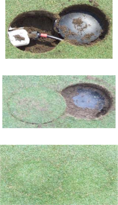
f. Replace greens mix and sod
g. Test sensor with sniffer software
- 5 -
Use the sniffer installed on your lap-top to verify that the SSN can be heard. The
sniffer will show a “one-hop” message type with the origin equal to the Node ID.
h. Use the GPS device (or measure the distance to the sensor from 2sprinkler heads to
determine the sensor location.
i.
Record the sensor location in a log to be kept with the superintendent.

- 6 -
FCC/IC COMPLIANT STATEMENT
NOTE: SSB1000CB has been tested and found to comply with the limits for a Class A digital device, pursuant to part 15 of the FCC
Rules. These limits are designed to pro-vide reasonable protection against harmful interference when the equipment is operated in a
commercial environment. This equipment generates, uses, and can radiate radio frequency energy and, if not installed and used in
accordance with the instruction manual, may cause harmful interference to radio communications. Operation of this equipment in a
residential area is likely to cause harmful interference in which case the user will be required to correct the interference at his own
expense.
Changes or modifications not expressly approved by the party responsible for compliance could void the user’s authority to operate the
equipment.
This equipment complies with the FCC RF radiation exposure limits set forth for an uncontrolled environment. This equipment should be
installed and operated with a minimum distance of 20 centimeters between the radiator and your body.
This transmitter must not be co-located or operating in conjunction with any other antenna or transmitter.
This Class A digital apparatus complies with Canadian ICES-003.
Cet appareil numérique de la classe A est conforme à la norme NMB-003 du Canada.
Advanced Sensor Technology Crossbow Technology, Inc
11231 US Highway One, Suite 384 4145 N. First St.
N. Palm Beach, Florida 33408 San Jose, CA95134