Counters And Ratemeters Crouzet Control Overview EN
2016-02-23
: Crouzet Crouzet-Control Overview Counters En Crouzet-Control_Overview_Counters_EN library assets
Open the PDF directly: View PDF ![]() .
.
Page Count: 80
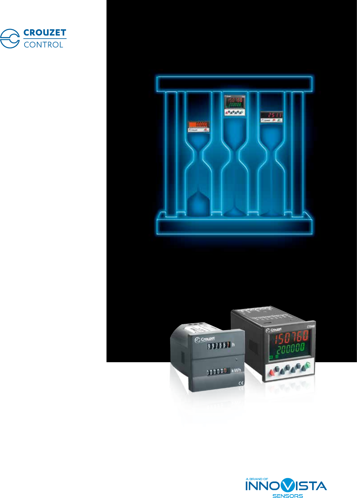
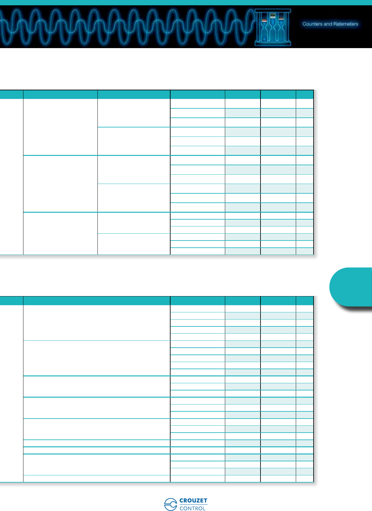
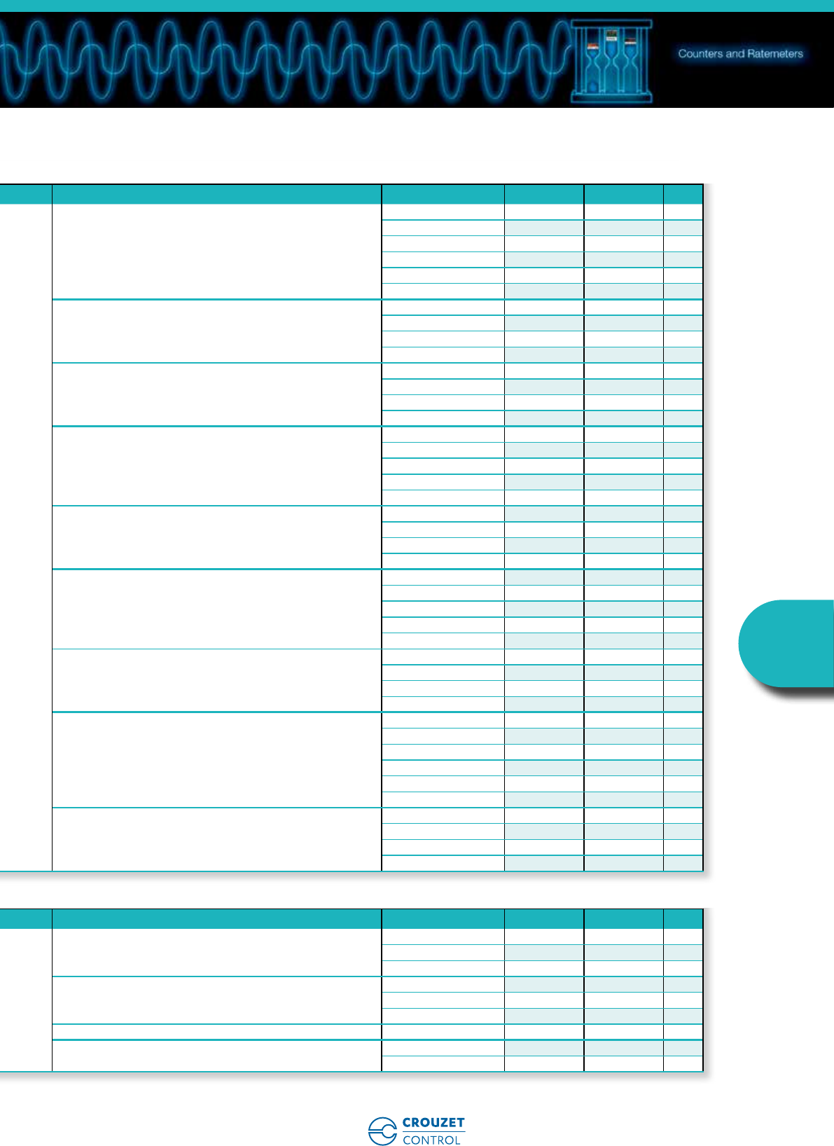
Counters and Ratemeters
Counting accuracy
www.crouzet-control.com
www.crouzet-control.com
2
Presentation
Expert in the design of efficient and innovative monitoring & control products, Crouzet Control,
supported by an experienced worldwide team, offers a broad range of industry standard and
application specific adapted products in timing, control relays and counting functions.
Crouzet Control is a brand of InnoVista Sensors™.
With operations around the globe, Crouzet Control is constantly monitoring its customers' needs.
Its sales teams, technicians and designers combine all their skills to adapt products to customer
specifications, both in terms of the application and cost.
Crouzet Control also ensures that its products are manufactured in compliance with quality and
environmental standards (factories certified ISO 9001, 14001 and OHSAS 18001, eco-design).
With its industrial and logistic flexibility Crouzet Control is able to deliver products, whether small-
scale or mass production items, in the best possible timescale.
Within this counter catalogue,
Crouzet Control presents:
Over 120 recently launched ergonomic counters for better equipment integration including
small formats..
New electromechanical range:
• Dual function hour counter and energy meter
• Dual function hour and impulse counter displays
New electronic range:
• Counters with backlit double LCD or two colour display
• Multi-function Counters
• Counters that integrate a Tachometer function
In addition to this catalogue, the www.crouzet-control.com
website offers the latest tools, available as free downloads,
including M3 Soft software, technical data sheets for each
product and installation manuals.
Crouzet Control

www.crouzet-control.com 3
InnoVista Sensors™ is a worldwide industrial specialist of sensors, controllers and actuators for
automated systems.
Through its brands, Crouzet Aerospace, Crouzet Automation, Crouzet Control, Crouzet Motors,
Crouzet Switches and Systron Donner Inertial, InnoVista Sensors™ offers a wide range of reliable,
efficient and customizable components dedicated to the Aerospace & Defence, Transportation
and Industrial market and segments.
Thanks to the recognized expertise of its teams and a strong innovation policy, InnoVista Sensors™
brings performance enhancing solutions to its customers worldwide.
InnoVista Sensors™
your trusted partner of choice to
face industrial challenges of today
and tomorrow
Production
Sales subsidiaries
The Crouzet Control team worldwide
Presentation
www.crouzet-control.com
4
The basics
A counter, a ratemeter
How can they be defined in simple
terms?
A counter, a ratemeter
To execute which actions?
Up counting
Down counting
Informing
Displaying
Tripping
Actuating Measuring
Chronometer timing
Up counting, Down counting
For up counting or down counting a number of parts, events, a
running time, the counter is the ideal solution. There are different
types of counter with the following functions: up/down counter, batch
counter, ratemeter, chronometer, multi-totalizer, elapsed time counter,
impulse counter.
Informing, Displaying
A counter can allow a user to be informed and to display data and
quantities easily. The data displayed can be read directly on the front
panel.
Tripping, Actuating
A counter can be used to trip an action or an intervention on a
machine. The outputs actuate directly and/or transmit data to the
control system.
Measuring, Chronometer timing
A counter can be used to schedule preventive maintenance. The
machine running time is measured and the duration of an action
timed with a chronometer.
In addition to this catalogue, the www.crouzet-control.com
website offers technical data sheets for each product and
installation manuals, available as free downloads.
A counter can be used to count a number of actions or events.
It thus participates in production management and preventive maintenance.
A ratemeter can be used to display the speed of rotation of a motor in real time.
www.crouzet-control.com 5
Counters
and
Ratemeters
The basics
Crouzet Control counters and ratemeters
A digital range and
an electromechanical range
• For fast count applications, a high-speed
counting frequency: up to 50 kHz.
• A two-colour or backlit LCD dual display
for ease of reading.
• Considerable space saving due to dual-
function electromechanical and electronic
ranges.
• A complete output operating logic to cover
complex applications.
• Easier maintenance thanks to removable
connectors (CTR48).
• An enhanced multifunction electronic range
for optimised stocks.
Crouzet Control counters and ratemeters
Their features:
CEM48CTR48
Operating
time
Power
used
Mode
Enable
Preset
settings
www.crouzet-control.com
6
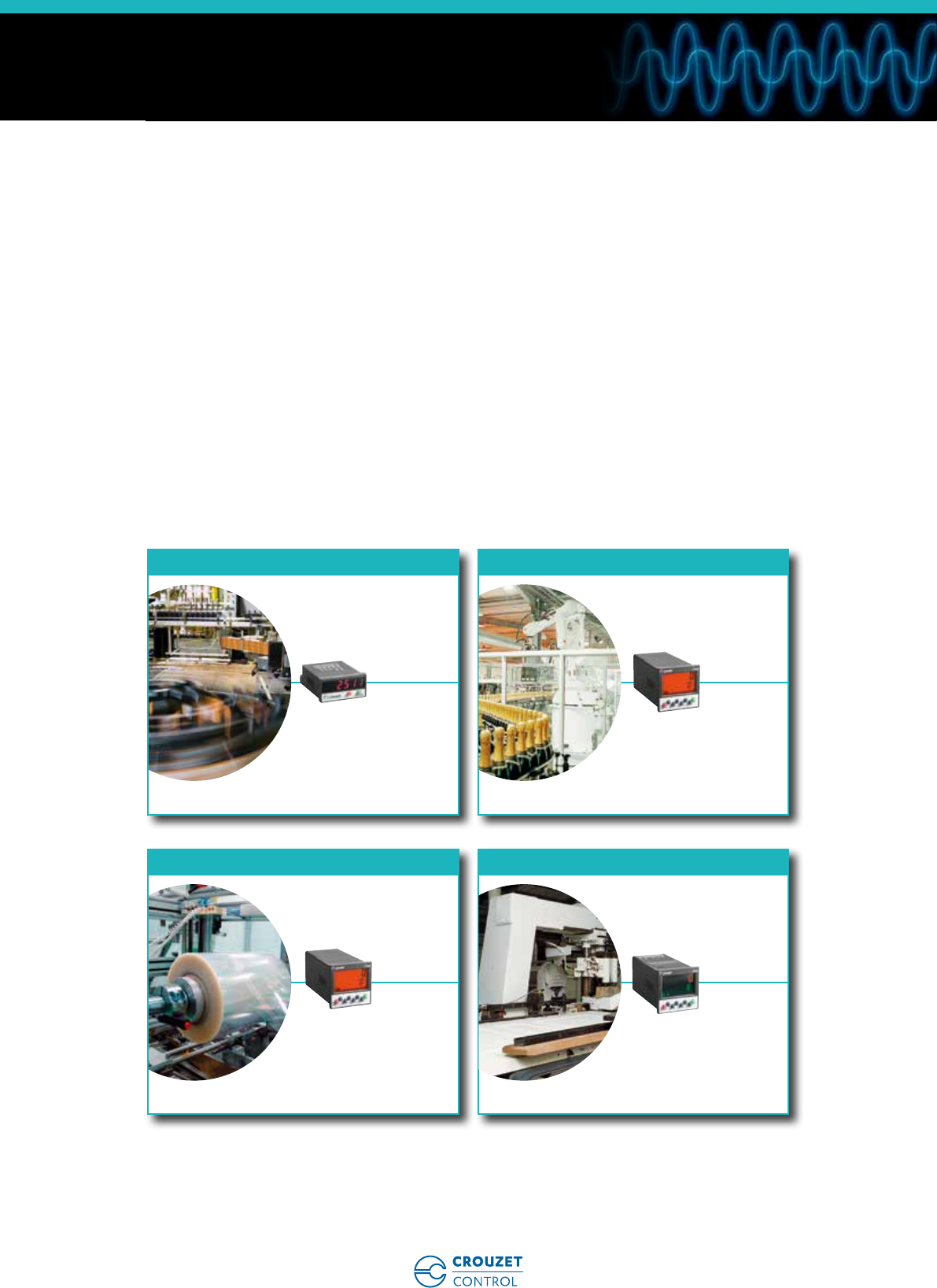
Speed measurement and control
on shrink wrapping machine.
Calculation of cut length on
wood and paper machines.
Managing quantities -
Packaging by unit, batch or
series of batches.
Managing quantities -
Calculation of distance
of travel.
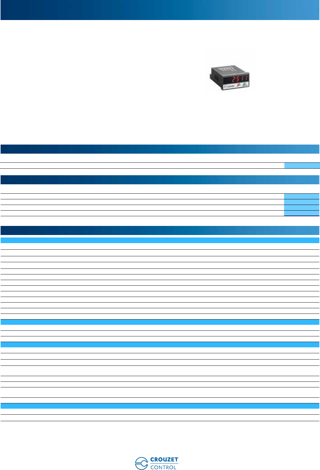
ELECTRONIC COUNTER
CTR24L 2511
ELECTRONIC COUNTER
CTR48
ELECTRONIC COUNTER
CTR48
ELECTRONIC COUNTER
CTR48
Tachometer systems
Metric counting
Counting quantities
Position control
Crouzet Control counters and ratemeters
Where are they found?
In electrical cabinets associated with other automation functions for the following markets:
• Industrial automation systems
• Building equipment
• Industrial machines
• Medical
Applications
www.crouzet-control.com 7
Counters
and
Ratemeters
Control of conveyor
movement speed.
Counting operating hours
and counting the number
of starts.
Combined impulse and hour
counters - Maintenance.
Start counters and
operating time counters.
Combined ratemeter and
counter for controlling the
position and speed of a
router.
Counting operating hours,
energy consumption.
Counting and display of
operating times.
Event management,
wear control.
RATEMETER
CTR24L 2511
ELECTROMECHANICAL
HOUR AND IMPULSE
COUNTER
CMM48
ELECTRONIC COUNTER
CTR24L 2514
ELECTRONIC RATEMETER AND
COUNTERS
CTR24L 2513
ELECTROMECHANICAL
HOUR AND ENERGY
COUNTER
CEM48
HOUR COUNTER
CTR24 2323
Assembly line speed
Compressors
Lifts
Milling machine
Dehumidifiers
UV lamp
Applications
www.crouzet-control.com
8
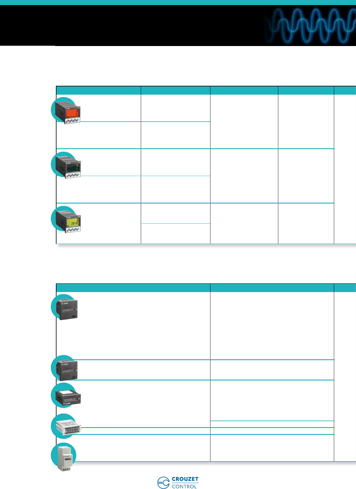
Selection guide
Electronic counters
24 x 48 multifunction counters without preselection
Functions Modes Multiplication coefficient/
Decimal point Max. counting speed Display Counting capacity Supply Part number Type Page
Totalizer
or Hour counter
or Ratemeter
Dir/up.dn/up.up
Ph/2-ph/4-ph Yes/Yes 50 kHz
LED
999,999
10 C 30 V c87 623 570 CTR24L - 2511 32
Start/Stop No/Yes 999,999 hrs 0.001 s C 999,999 hrs
sec -1/min -1 Yes/Yes 50 kHz 999,999
Double totalizer
Independent inputs
(A and B)
Counting
A/B/A-B/A+B
AdivB/%AB
Yes/Yes 25 kHz LED 999,999 10 C 30 V c87 623 571 CTR24L - 2512 36
Totalizer and
Ratemeter
Independent inputs
Dir/up.dn/up.up
Ph/2-ph/4-ph Yes/Yes 30 kHz LED 999,999 10 C 30 V c87 623 572 CTR24L - 2513 40
sec -1/min -1
Double totalizer
Common input
Counting
(total/partial) Yes/Yes 50 kHz LED 999,999 10 C 30 V c87 623 573 CTR24L - 2514 44
Totalizer
+ Ratemeter
or Totalizer
+ Totalizer
or Totalizer + Hour
or Hour + Hour
Counting + sec -1/min -1
Yes/Yes
35 kHz
LED
999,999
10 C 30 V c87 623 574 CTR24L - 2515 48
Counting 50 kHz
Counting + Start/Stop 40 kHz 999,999
0.001 s C 999,999 hrs
999,999 hrs
Start/Stop No/Yes 999,999 hrs 0.001 s C 999,999 hrs
24 x 48 counters without preselection
Functions Inputs/Reset Max. counting speed Display Counting capacity Supply Part number Type Page
Hour
PNP/Contact
99,999.99 hrs LCD 0.1 s C 99,999.99 hrs Lithium battery
87 622 161 CTR24 - 2223 52
NPN/Contact 87 622 162 CTR24 - 2233 52
Voltage/Contact 87 622 170 CTR24 - 2224 52
Hour
PNP/Contact
99,999.99 hrs Orange
(backlit) 0.1 s C 99,999.99 hrs Lithium battery
87 622 181 CTR24 - 2323 52
NPN/Contact 87 622 182 CTR24 - 2333 52
Voltage/Contact 87 622 190 CTR24 - 2324 52
Totalizer
Voltage/Contact
99,999,999 LCD 99,999,999 Lithium battery
87 610 340 CP2 - 2108 52
PNP/Contact 87 622 061 CTR24 - 2241 56
NPN/Contact 87 622 062 CTR24 - 2251 56
Voltage/Contact 87 622 070 CTR24 - 2242 56
Totalizer
PNP/Contact
99,999,999 Orange
(backlit) 99,999,999 Lithium battery
87 622 081 CTR24 - 2341 56
NPN/Contact 87 622 082 CTR24 - 2351 56
Voltage/Contact 87 622 090 CTR24 - 2342 56
www.crouzet-control.com 9
Counters
and
Ratemeters
Selection guide
Electronic counters
24 x 48 multifunction counters without preselection
Functions Modes Multiplication coefficient/
Decimal point Max. counting speed Display Counting capacity Supply Part number Type Page
Totalizer
or Hour counter
or Ratemeter
Dir/up.dn/up.up
Ph/2-ph/4-ph Yes/Yes 50 kHz
LED
999,999
10 C 30 V c87 623 570 CTR24L - 2511 32
Start/Stop No/Yes 999,999 hrs 0.001 s C 999,999 hrs
sec -1/min -1 Yes/Yes 50 kHz 999,999
Double totalizer
Independent inputs
(A and B)
Counting
A/B/A-B/A+B
AdivB/%AB
Yes/Yes 25 kHz LED 999,999 10 C 30 V c87 623 571 CTR24L - 2512 36
Totalizer and
Ratemeter
Independent inputs
Dir/up.dn/up.up
Ph/2-ph/4-ph Yes/Yes 30 kHz LED 999,999 10 C 30 V c87 623 572 CTR24L - 2513 40
sec -1/min -1
Double totalizer
Common input
Counting
(total/partial) Yes/Yes 50 kHz LED 999,999 10 C 30 V c87 623 573 CTR24L - 2514 44
Totalizer
+ Ratemeter
or Totalizer
+ Totalizer
or Totalizer + Hour
or Hour + Hour
Counting + sec -1/min -1
Yes/Yes
35 kHz
LED
999,999
10 C 30 V c87 623 574 CTR24L - 2515 48
Counting 50 kHz
Counting + Start/Stop 40 kHz 999,999
0.001 s C 999,999 hrs
999,999 hrs
Start/Stop No/Yes 999,999 hrs 0.001 s C 999,999 hrs
24 x 48 counters without preselection
Functions Inputs/Reset Max. counting speed Display Counting capacity Supply Part number Type Page
Hour
PNP/Contact
99,999.99 hrs LCD 0.1 s C 99,999.99 hrs Lithium battery
87 622 161 CTR24 - 2223 52
NPN/Contact 87 622 162 CTR24 - 2233 52
Voltage/Contact 87 622 170 CTR24 - 2224 52
Hour
PNP/Contact
99,999.99 hrs Orange
(backlit) 0.1 s C 99,999.99 hrs Lithium battery
87 622 181 CTR24 - 2323 52
NPN/Contact 87 622 182 CTR24 - 2333 52
Voltage/Contact 87 622 190 CTR24 - 2324 52
Totalizer
Voltage/Contact
99,999,999 LCD 99,999,999 Lithium battery
87 610 340 CP2 - 2108 52
PNP/Contact 87 622 061 CTR24 - 2241 56
NPN/Contact 87 622 062 CTR24 - 2251 56
Voltage/Contact 87 622 070 CTR24 - 2242 56
Totalizer
PNP/Contact
99,999,999 Orange
(backlit) 99,999,999 Lithium battery
87 622 081 CTR24 - 2341 56
NPN/Contact 87 622 082 CTR24 - 2351 56
Voltage/Contact 87 622 090 CTR24 - 2342 56
The counters and ratemeters accessories guide is available on the product data sheets which can be downloaded from the website www.crouzet-control.com
www.crouzet-control.com
10
Selection guide
Electromechanical counters
48 x 48 multifunction counters with preselection
Functions Number of preset(s) Max. counting speed Display Counting capacity Outputs Supply Part number Type Page
Preselection counter
Ratemeter
Chronometer
Multi-totalizer
1
40 KHz
Backlit LCD (orange)
extra-bright
2 lines
-999,999 C 999,999
1 x 5 A changeover
1 solid state
10 C 30 V c87 621 111 CTR48 18
24 V a87 621 112 CTR48 18
90 C 260 V a87 621 115 CTR48 18
Preselection counter
Ratemeter
Chronometer
Multi-totalizer
Batch counter
2
1 x 5 A changeover
1 x 5 A N/O
2 solid state
10 C 30 V c87 621 121 CTR48 18
24 V a87 621 122 CTR48 18
90 C 260 V a87 621 125 CTR48 18
Preselection counter
Ratemeter
Chronometer
Multi-totalizer
1
40 KHz
Two-colour LCD
(red and green)
2 lines
-999,999 C 999,999
1 x 5 A changeover
1 solid state
10 C 30 V c87 621 211 CTR48 18
24 V a87 621 212 CTR48 18
90 C 260 V a87 621 215 CTR48 18
Preselection counter
Ratemeter
Chronometer
Multi-totalizer
Batch counter
2
1 x 5 A changeover
1 x 5 A N/O
2 solid state
10 C 30 V c87 621 221 CTR48 18
24 V a87 621 222 CTR48 18
90 C 260 V a87 621 225 CTR48 18
Preselection counter
Chronometer
1
5 KHz Backlit LCD (green)
2 lines -999,999 C 999,999
1 x 3 A changeover
11 C 30 V c87 629 111 CTR48E 26
115 V a87 629 113 CTR48E 26
230 V a87 629 114 CTR48E 26
21 x 3 A changeover
1 x 3 A N/O
11 C 30 V c87 629 121 CTR48E 26
115 V a87 629 123 CTR48E 26
230 V a87 629 124 CTR48E 26
Hour counters
Dimensions (mm) Counting capacity Frequency Supply Part number Type Page
48 x 48 99,999.99
50 Hz a
20 C 30 V a99 772 710 CHM48 60
42 C 48 V a99 772 711 CHM48 60
100 C 130 V a99 772 712 CHM48 60
360 C 440 V a99 772 713 CHM48 60
187 C 264 V a99 772 714 CHM48 60
60 Hz a
20 C 30 V a99 772 718 CHM48 60
42 C 48 V a99 772 719 CHM48 60
100 C 130 V a99 772 715 CHM48 60
360 C 440 V a99 772 717 CHM48 60
187 C 264 V a99 772 716 CHM48 60
48 x 48 999,999.99 c
10 C 30 V c99 772 810 CHM48 60
36 C 80 V c99 772 811 CHM48 60
100 C 130 V c99 772 812 CHM48 60
24 x 48 99,999.99
50 Hz a
20 C 30 V a99 782 710 CHM24 62
100 C 130 V a99 782 712 CHM24 62
187 C 264 V a99 782 714 CHM24 62
60 Hz a
20 C 30 V a99 782 718 CHM24 62
100 C 130 V a99 782 715 CHM24 62
187 C 264 V a99 782 716 CHM24 62
999,999.99 c10 C 30 V c99 782 810 CHM24 62
15 x 32 99,999.99 c4.5 C 35 V c99 792 810 CHM15 64
Modular
DIN rail
35 mm
99,999.99 50 Hz a
24 V a99 793 710 CHMDR 65
115 V a99 793 712 CHMDR 65
230 V a99 793 714 CHMDR 65
c10 C 27 V c99 793 810 CHMDR 65
www.crouzet-control.com 11
Counters
and
Ratemeters
Selection guide
48 x 48 multifunction counters with preselection
Functions Number of preset(s) Max. counting speed Display Counting capacity Outputs Supply Part number Type Page
Preselection counter
Ratemeter
Chronometer
Multi-totalizer
1
40 KHz
Backlit LCD (orange)
extra-bright
2 lines
-999,999 C 999,999
1 x 5 A changeover
1 solid state
10 C 30 V c87 621 111 CTR48 18
24 V a87 621 112 CTR48 18
90 C 260 V a87 621 115 CTR48 18
Preselection counter
Ratemeter
Chronometer
Multi-totalizer
Batch counter
2
1 x 5 A changeover
1 x 5 A N/O
2 solid state
10 C 30 V c87 621 121 CTR48 18
24 V a87 621 122 CTR48 18
90 C 260 V a87 621 125 CTR48 18
Preselection counter
Ratemeter
Chronometer
Multi-totalizer
1
40 KHz
Two-colour LCD
(red and green)
2 lines
-999,999 C 999,999
1 x 5 A changeover
1 solid state
10 C 30 V c87 621 211 CTR48 18
24 V a87 621 212 CTR48 18
90 C 260 V a87 621 215 CTR48 18
Preselection counter
Ratemeter
Chronometer
Multi-totalizer
Batch counter
2
1 x 5 A changeover
1 x 5 A N/O
2 solid state
10 C 30 V c87 621 221 CTR48 18
24 V a87 621 222 CTR48 18
90 C 260 V a87 621 225 CTR48 18
Preselection counter
Chronometer
1
5 KHz Backlit LCD (green)
2 lines -999,999 C 999,999
1 x 3 A changeover
11 C 30 V c87 629 111 CTR48E 26
115 V a87 629 113 CTR48E 26
230 V a87 629 114 CTR48E 26
21 x 3 A changeover
1 x 3 A N/O
11 C 30 V c87 629 121 CTR48E 26
115 V a87 629 123 CTR48E 26
230 V a87 629 124 CTR48E 26
Hour counters
Dimensions (mm) Counting capacity Frequency Supply Part number Type Page
48 x 48 99,999.99
50 Hz a
20 C 30 V a99 772 710 CHM48 60
42 C 48 V a99 772 711 CHM48 60
100 C 130 V a99 772 712 CHM48 60
360 C 440 V a99 772 713 CHM48 60
187 C 264 V a99 772 714 CHM48 60
60 Hz a
20 C 30 V a99 772 718 CHM48 60
42 C 48 V a99 772 719 CHM48 60
100 C 130 V a99 772 715 CHM48 60
360 C 440 V a99 772 717 CHM48 60
187 C 264 V a99 772 716 CHM48 60
48 x 48 999,999.99 c
10 C 30 V c99 772 810 CHM48 60
36 C 80 V c99 772 811 CHM48 60
100 C 130 V c99 772 812 CHM48 60
24 x 48 99,999.99
50 Hz a
20 C 30 V a99 782 710 CHM24 62
100 C 130 V a99 782 712 CHM24 62
187 C 264 V a99 782 714 CHM24 62
60 Hz a
20 C 30 V a99 782 718 CHM24 62
100 C 130 V a99 782 715 CHM24 62
187 C 264 V a99 782 716 CHM24 62
999,999.99 c10 C 30 V c99 782 810 CHM24 62
15 x 32 99,999.99 c4.5 C 35 V c99 792 810 CHM15 64
Modular
DIN rail
35 mm
99,999.99 50 Hz a
24 V a99 793 710 CHMDR 65
115 V a99 793 712 CHMDR 65
230 V a99 793 714 CHMDR 65
c10 C 27 V c99 793 810 CHMDR 65
The counters and ratemeters accessories guide is available on the product data sheets which can be downloaded from the website www.crouzet-control.com
www.crouzet-control.com
12
Selection guide
Impulse counters
Dimensions (mm) Reset to zero Counting capacity Supply Part number Type Page
15 x 32
Clip-fixing No 9,999,999
24 V a - 50/60 Hz 99 778 710 CIM 15 76
115 V a - 50/60 Hz 99 778 712 CIM 15 76
230 V a - 50/60 Hz 99 778 714 CIM 15 76
5 V c99 778 805 CIM 15 76
12 V c99 778 806 CIM 15 76
24 V c99 778 810 CIM 15 76
24 x 48
Clip-fixing No 999,999
24 V a - 50/60 Hz 99 777 710 CIM 24 70
230 V a - 50/60 Hz 99 777 714 CIM 24 70
12 V c99 777 815 CIM 24 70
24 V c99 777 810 CIM 24 70
24 x 48
Clip-fixing Yes 99,999
24 V a - 50/60 Hz 99 777 720 CIM 24 70
230 V a - 50/60 Hz 99 777 724 CIM 24 70
12 V c99 777 825 CIM 24 70
24 V c99 777 820 CIM 24 70
24 x 48
Screw-fixing No 999,999
24 V a - 50/60 Hz 99 776 904 CIM 24 x 48 78
115 V a - 50/60 Hz 99 776 902 CIM 24 x 48 78
230 V a - 50/60 Hz 99 776 901 CIM 24 x 48 78
24 V c99 776 907 CIM 24 x 48 78
110 V c99 776 905 CIM 24 x 48 78
24 x 48
Screw-fixing Yes 99,999
24 V a - 50/60 Hz 99 776 924 CIM 24 x 48 78
115 V a - 50/60 Hz 99 776 922 CIM 24 x 48 78
230 V a - 50/60 Hz 99 776 921 CIM 24 x 48 78
24 V c99 776 927 CIM 24 x 48 78
36 x 37
Screw-fixing No 999,999
24 V a - 50/60 Hz 99 776 604 CIM 36 x 37 72
115 V a - 50/60 Hz 99 776 602 CIM 36 x 37 72
230 V a - 50/60 Hz 99 776 601 CIM 36 x 37 72
24 V c99 776 607 CIM 36 x 37 72
110 V c99 776 605 CIM 36 x 37 72
36 x 37
Screw-fixing Yes 99,999
24 V a - 50/60 Hz 99 776 613 CIM 36 x 37 72
115 V a - 50/60 Hz 99 776 611 CIM 36 x 37 72
230 V a - 50/60 Hz 99 776 610 CIM 36 x 37 72
24 V c99 776 616 CIM 36 x 37 72
36 x 48
Screw-fixing No 999,999
24 V a - 50/60 Hz 99 776 704 CIM 36 x 48 74
115 V a - 50/60 Hz 99 776 702 CIM 36 x 48 74
230 V a - 50/60 Hz 99 776 701 CIM 36 x 48 74
24 V c99 776 707 CIM 36 x 48 74
48 V c99 776 736 CIM 36 x 48 74
110 V c99 776 705 CIM 36 x 48 74
36 x 48
Screw-fixing Yes 99,999
24 V a - 50/60 Hz 99 776 713 CIM 36 x 48 74
115 V a - 50/60 Hz 99 776 711 CIM 36 x 48 74
230 V a - 50/60 Hz 99 776 710 CIM 36 x 48 74
24 V c99 776 716 CIM 36 x 48 74
Dual function 48 x 48 counters
Functions Reset to zero Counting capacity Frequency Supply Part number Type Page
Impulse
Hour No
9,999,999
99,999.99 hrs
50 Hz a
20 C 30 V a99 779 710 CMM48 68
100 C 130 V a99 779 712 CMM48 68
187 C 264 V a99 779 714 CMM48 68
60 Hz a
20 C 30 V a99 779 718 CMM48 68
100 C 130 V a99 779 715 CMM48 68
187 C 264 V a99 779 716 CMM48 68
9,999,999/999,999.99 hrs c10 C 30 V c99 779 810 CMM48 68
Hour
Energy No 99,999.9 hrs
99,999.9 kWh 50 Hz a115 V a99 780 712 CEM48 68
230 V a99 780 714 CEM48 68
www.crouzet-control.com 13
Counters
and
Ratemeters
Selection guide
Impulse counters
Dimensions (mm) Reset to zero Counting capacity Supply Part number Type Page
15 x 32
Clip-fixing No 9,999,999
24 V a - 50/60 Hz 99 778 710 CIM 15 76
115 V a - 50/60 Hz 99 778 712 CIM 15 76
230 V a - 50/60 Hz 99 778 714 CIM 15 76
5 V c99 778 805 CIM 15 76
12 V c99 778 806 CIM 15 76
24 V c99 778 810 CIM 15 76
24 x 48
Clip-fixing No 999,999
24 V a - 50/60 Hz 99 777 710 CIM 24 70
230 V a - 50/60 Hz 99 777 714 CIM 24 70
12 V c99 777 815 CIM 24 70
24 V c99 777 810 CIM 24 70
24 x 48
Clip-fixing Yes 99,999
24 V a - 50/60 Hz 99 777 720 CIM 24 70
230 V a - 50/60 Hz 99 777 724 CIM 24 70
12 V c99 777 825 CIM 24 70
24 V c99 777 820 CIM 24 70
24 x 48
Screw-fixing No 999,999
24 V a - 50/60 Hz 99 776 904 CIM 24 x 48 78
115 V a - 50/60 Hz 99 776 902 CIM 24 x 48 78
230 V a - 50/60 Hz 99 776 901 CIM 24 x 48 78
24 V c99 776 907 CIM 24 x 48 78
110 V c99 776 905 CIM 24 x 48 78
24 x 48
Screw-fixing Yes 99,999
24 V a - 50/60 Hz 99 776 924 CIM 24 x 48 78
115 V a - 50/60 Hz 99 776 922 CIM 24 x 48 78
230 V a - 50/60 Hz 99 776 921 CIM 24 x 48 78
24 V c99 776 927 CIM 24 x 48 78
36 x 37
Screw-fixing No 999,999
24 V a - 50/60 Hz 99 776 604 CIM 36 x 37 72
115 V a - 50/60 Hz 99 776 602 CIM 36 x 37 72
230 V a - 50/60 Hz 99 776 601 CIM 36 x 37 72
24 V c99 776 607 CIM 36 x 37 72
110 V c99 776 605 CIM 36 x 37 72
36 x 37
Screw-fixing Yes 99,999
24 V a - 50/60 Hz 99 776 613 CIM 36 x 37 72
115 V a - 50/60 Hz 99 776 611 CIM 36 x 37 72
230 V a - 50/60 Hz 99 776 610 CIM 36 x 37 72
24 V c99 776 616 CIM 36 x 37 72
36 x 48
Screw-fixing No 999,999
24 V a - 50/60 Hz 99 776 704 CIM 36 x 48 74
115 V a - 50/60 Hz 99 776 702 CIM 36 x 48 74
230 V a - 50/60 Hz 99 776 701 CIM 36 x 48 74
24 V c99 776 707 CIM 36 x 48 74
48 V c99 776 736 CIM 36 x 48 74
110 V c99 776 705 CIM 36 x 48 74
36 x 48
Screw-fixing Yes 99,999
24 V a - 50/60 Hz 99 776 713 CIM 36 x 48 74
115 V a - 50/60 Hz 99 776 711 CIM 36 x 48 74
230 V a - 50/60 Hz 99 776 710 CIM 36 x 48 74
24 V c99 776 716 CIM 36 x 48 74
Dual function 48 x 48 counters
Functions Reset to zero Counting capacity Frequency Supply Part number Type Page
Impulse
Hour No
9,999,999
99,999.99 hrs
50 Hz a
20 C 30 V a99 779 710 CMM48 68
100 C 130 V a99 779 712 CMM48 68
187 C 264 V a99 779 714 CMM48 68
60 Hz a
20 C 30 V a99 779 718 CMM48 68
100 C 130 V a99 779 715 CMM48 68
187 C 264 V a99 779 716 CMM48 68
9,999,999/999,999.99 hrs c10 C 30 V c99 779 810 CMM48 68
Hour
Energy No 99,999.9 hrs
99,999.9 kWh 50 Hz a115 V a99 780 712 CEM48 68
230 V a99 780 714 CEM48 68
The counters and ratemeters accessories guide is available on the product data sheets which can be downloaded from the website www.crouzet-control.com
www.crouzet-control.com
14
Connection diagrams
CTR24 counters
Connections
Types 2223 and 2323:
Part numbers:
• 87 622 161
• 87 622 181
Types 2233 and 2333:
Part numbers:
• 87 622 162
• 87 622 182
1. NC
2. Start/Stop input
3. Reset input
4. Enable front panel
Reset
5. Mode 1
(Time selection)
6. GND/Optional
backlighting -
(only 23xx)
7. Mode 2
(Time selection)
8. Optional
backlighting +
(only 23xx)
1. Common z
2. Start/Stop input
3. Reset input
4. Enable front panel
Reset
5. Mode 1
(Time selection)
6. GND/Optional
backlighting -
(only 23xx)
7. Mode 2
(Time selection)
8. Optional
backlighting +
(only 23xx)
Types 2224 and 2324:
Part numbers:
• 87 622 170
• 87 622 190
www.crouzet-control.com 15
Counters
and
Ratemeters
Connection diagrams
Types 2241 and 2341:
Part numbers:
• 87 622 061
• 87 622 081
Types 2251 and 2351:
Part numbers:
• 87 622 062
• 87 622 082
1. Fast count
2. Common z
3. Reset input
4. Enable front panel
Reset
5. NC
6. GND
7. Optional
backlighting -
(only 23xx)
8. Optional
backlighting +
(only 23xx)
1. Fast count
2. Slow count
3. Reset input
4. Enable front panel
Reset
5. Counting (counting
direction)
6. GND
7. Optional
backlighting -
(only 23xx)
8. Optional
backlighting +
(only 23xx)
Types 2242 and 2342:
Part numbers:
• 87 622 070
• 87 622 090
www.crouzet-control.com
16
Crouzet Control,
Technology and expertise,
behind every project
• Local support for all industrial projects.
• A multi-skilled team.
• A sales presence in over 40 countries.
• A Premium offer designed to ensure the excellence of products and services.
• Eco-design integrated in Crouzet's Offer Creation Process.
• Certifications: ISO 9001, ISO 14001, OHSAS 18001.
• Products which comply with international standards (UL, CSA, EC).
• A dynamic R&D department.
In addition to this catalogue, the www.crouzet-control.com
website offers the latest tools, available as free downloads,
including M3 Soft software, technical data sheets for each
product and installation manuals.

www.crouzet-control.com 17
To order:
Customer Service
Crouzet Control
Tel.: +33 (0) 475 802 102
customer.relation@crouzet.com
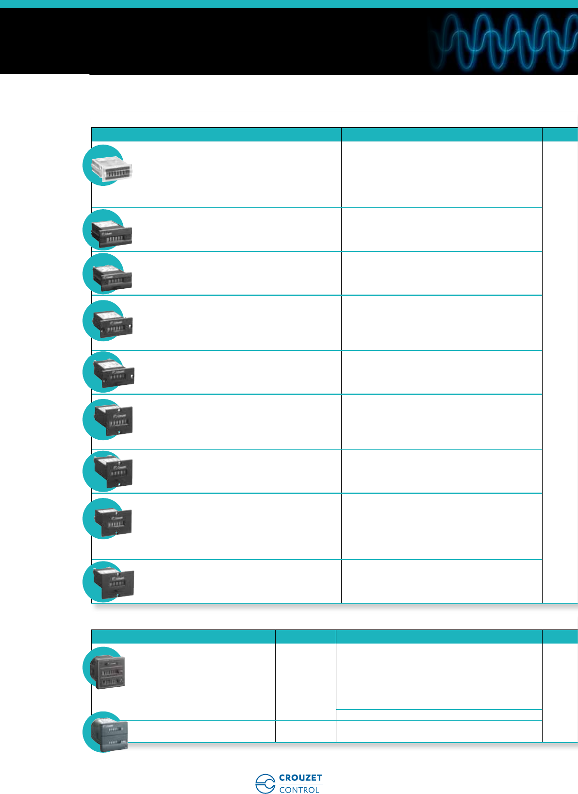
Data sheets
• Up counters / Down counters - 48 x 48 - CTR48 P. 18
• Up counters / Down counters - 48 x 48 - CTR48E - Essential P. 26
• Multifunction counter - LED 24 x 48 - CTR24L P. 32
• Multifunction counter with 2 totalizers - LED 24 x 48 - CTR24L P. 36
• Multifunction counter combining a totalizer and tachometer -
LED 24 x 48 - CTR24L P. 40
• Multifunction counter with 2 totalizers (total an partial function) with common input -
LED 24 x 48 - CTR24L P. 44
• "DUO" multifunction counter - LED 24 x 48 - CTR24L P. 48
• Hour counters without preselection - LCD 24 x 48 - CTR24 P. 52
• Totalizers without preselection - LCD 24 x 48 - CTR24 P. 56
• Hour counters 48 x 48 - CHM48 P. 60
• Hour counters 24 x 48 - CHM24 P. 62
• Hour counters 15 x 32 - CHM15 P. 64
• DIN rail mounting hour counters - CHMDR P. 65
• Dual-function counter (hour counter and watt-hour meter) 48 x 48 - CEM48 P. 66
• Dual-function counter (hour counter and impulse counter) 48 x 48 - CMM48 P. 68
• Impulse counters 24 x 48 - CIM24 P. 70
• Impulse counters 36 x 37 - CIM P. 72
• Impulse counters 36 x 48 - CIM P. 74
• Impulse counters with built-in fixing clip15 x 32 - CIM15 P. 76
• Screw-fixing implulse counters 24 x 48 - CIM P. 78
www.crouzet-control.com
18
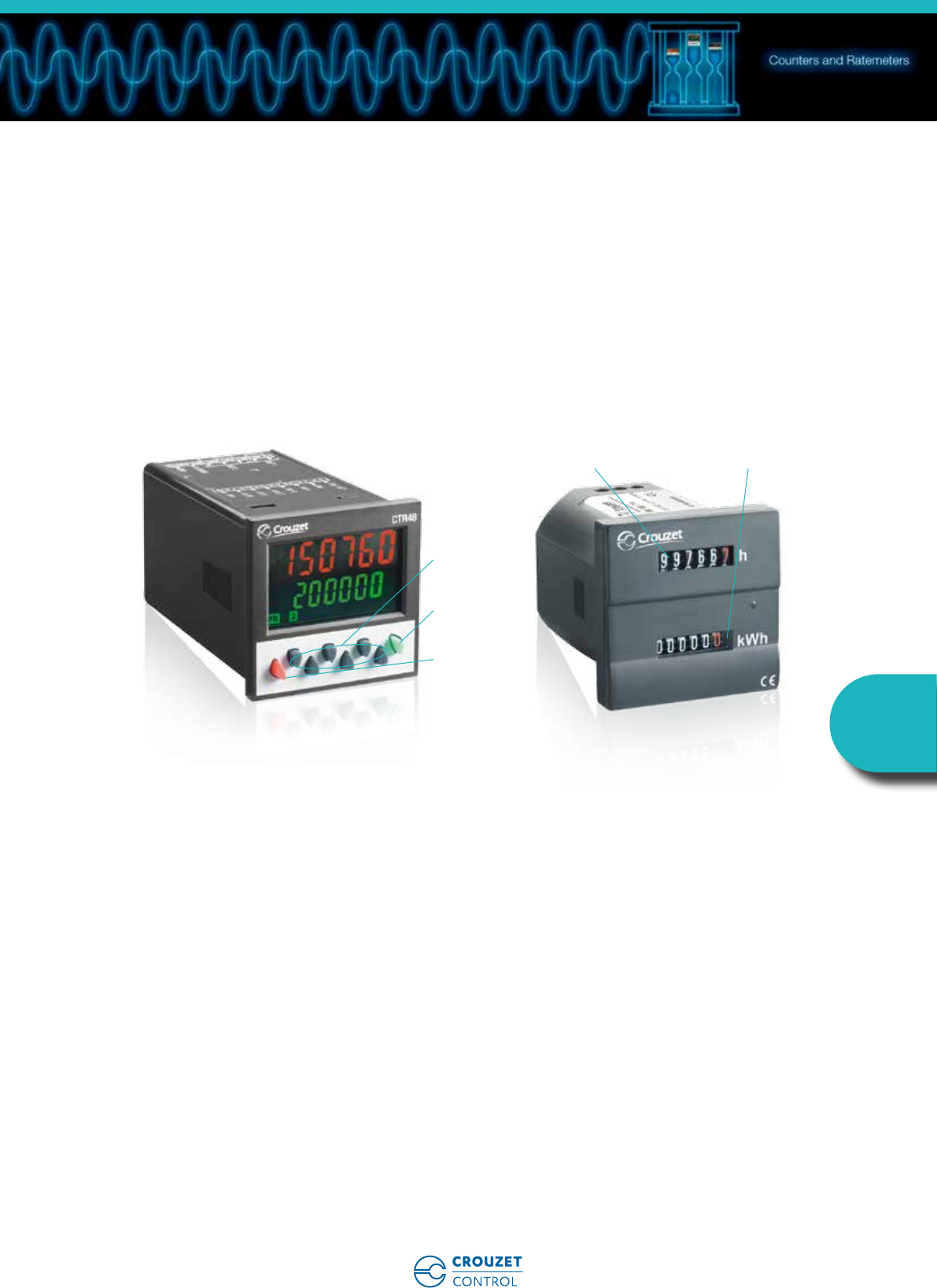
1
➜ Up counters / Down counters - 48 x 48 - CTR48
■ Counter, Tachometer, Chronometer, Multi-totalizer,
Batch counter, Preselection totalizer
■ Maximum input frequency 40 kHz
■ Simple parameter setting, configuration using text
menus
■ Easy modification of presets
■ Scaling factor
■ 5 A changeover relay and solid state output
■ Removable connectors
■ Backlit LCD display (orange) : 2 lines, 6 digits or
multicoloured display (green-red)
■ IP 65 sealed panel
■ Option of locking the keypad, completely or partially
(preset, programming)
■ Accessories for 72 x 72 or 55 x 55 cut-out,
DIN rail adaptor
Type Functions Preset Voltages Output Code
Orange
backlight LCD
display
Counter, Tachometer, Chronometer, Preselection
multi-totalizer
110 ➞30 Vc1 changeover relay,
1 solid state
87621111
Counter, Tachometer, Chronometer, Preselection
multi-totalizer
124 Va1 changeover relay,
1 solid state
87621112
Counter, Tachometer, Chronometer, Preselection
multi-totalizer
190 ➞260 Va1 changeover relay,
1 solid state
87621115
Counter, Tachometer, Chronometer, Multi-totalizer,
Batch counter, Preselection totalizer
210 ➞30 Vc1 changeover relay,
1 NO relay, 2 solid state
87621121
Counter, Tachometer, Chronometer, Multi-totalizer,
Batch counter, Preselection totalizer
224 Va1 changeover relay,
1 NO relay, 2 solid state
87621122
Counter, Tachometer, Chronometer, Multi-totalizer,
Batch counter, Preselection totalizer
290 ➞260 Va1 changeover relay,
1 NO relay, 2 solid state
87621125
Multicoloured
LCD display
(green-red)
Counter, Tachometer, Chronometer, Preselection
multi-totalizer
110 ➞30 Vc1 changeover relay,
1 solid state
87621211
Counter, Tachometer, Chronometer, Preselection
multi-totalizer
124 Va1 changeover relay,
1 solid state
87621212
Counter, Tachometer, Chronometer, Preselection
multi-totalizer
190 ➞260 Va1 changeover relay,
1 solid state
87621215
Counter, Tachometer, Chronometer, Multi-totalizer,
Batch counter, Preselection totalizer
210 ➞30 Vc1 changeover relay,
1 NO relay, 2 solid state
87621221
Counter, Tachometer, Chronometer, Multi-totalizer,
Batch counter, Preselection totalizer
224 Va1 changeover relay,
1 NO relay, 2 solid state
87621222
Counter, Tachometer, Chronometer, Multi-totalizer,
Batch counter, Preselection totalizer
290 ➞260 Va1 changeover relay,
1 NO relay, 2 solid state
87621225
Description Code
Adaptor for 72 x 72 mm cut-out 26546842
Adaptor for 55 x 55 mm cut-out 26546846
DIN rail adaptor 26546841
Electronic multifunction counters with preselection
Part numbers
Accessories
www.crouzet-control.com 19
2
Environmental characteristics
Supply 10 ➞30 Vc / 24 V a / 90 ➞260 Va
Relative humidity (no condensation) EN 60068-2-30 40/93% RLF
Altitude 0 < 2000 m
Certifications UL - cULus (pending) - CE
Vibration resistance in 3 axes 10-55 Hz / 1 min / XYZ EN 60068-2-6: 30 min. in each direction
Connection by screw terminals Removable
Protection Conforming to standard EN 60529 IP65 for panel / IP20 for connections
Front panel watertight seal ✓
Temperature limits use (°C) -20 ➞+65
Temperature limits stored (°C) -25 ➞+75
Weight (g) 150 c version
250 a version
General characteristics
Reset to zero or to preset On panel: if not locked during programming
Electrical: automatic, voltage or solid state (NPN or PNP depending on
programming)
Minimum pulse time Impulse counter: < 15 ms
Chronometer: 500 µs
Option to protect against reset from front panel ✓
Scale factor (each input pulse is multiplied by this figure) 00.0001 ➞99.9999
Scaling factor (each input impulse is divided by this value) 01.0000 ➞99.9999
Decimal point selectable for ease of reading 0
0.0
0.00
0.000
0.0000
0.00000
Sensor supply version a24 Vc -20/+15% 50 mA
Programming and current value backed up via EEPROM memory ✓
Service life 10 years
Operating characteristics
Functions Preselection counter, Tachometer, Chronometer, Multi-totalizer, Batch
counters, Totalizer
Number of presets 1 or 2
Display LCD with orange backlighting/Multicoloured LCD (green-red)
Height digits (mm) LCD 9
Display details - 999 999 ➞999 999
Input characteristics
Inputs 2 counter inputs
1 reset input, 1 gate input
Input modes Dir: Directional
AS: up/dn
AA: up/up
PP: phase
PP2: phase 2
PP4: phase 4
Input type Voltage or solid state
High level 8 Vc ➞30 Vc
Low level 0 ➞2 Vc
Solid state output characteristics
Maximum current 30 mA
Max. voltage 10 ➞30 Vc for the c version
24 Vc -20/+15%
Relay output characteristics
Changeover relay ✓
NO contact Depending on version
Maximum current 5 A
Minimum current 10 mA
Maximum voltage 30 Vc / 250 Va
Min. voltage 5 Vz
Response time < 13 ms
Mechanical life (operations) 20 x 106
Number of operations to 5 A 5 x 10⁴
Output modes: maintained or pulsed 0.01 ➞99.99 s
General characteristics
www.crouzet-control.com
20
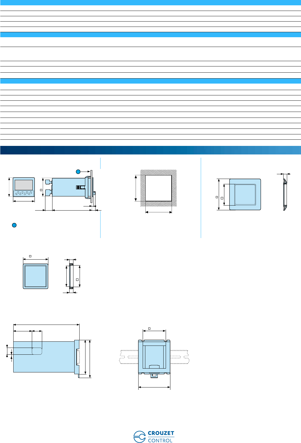
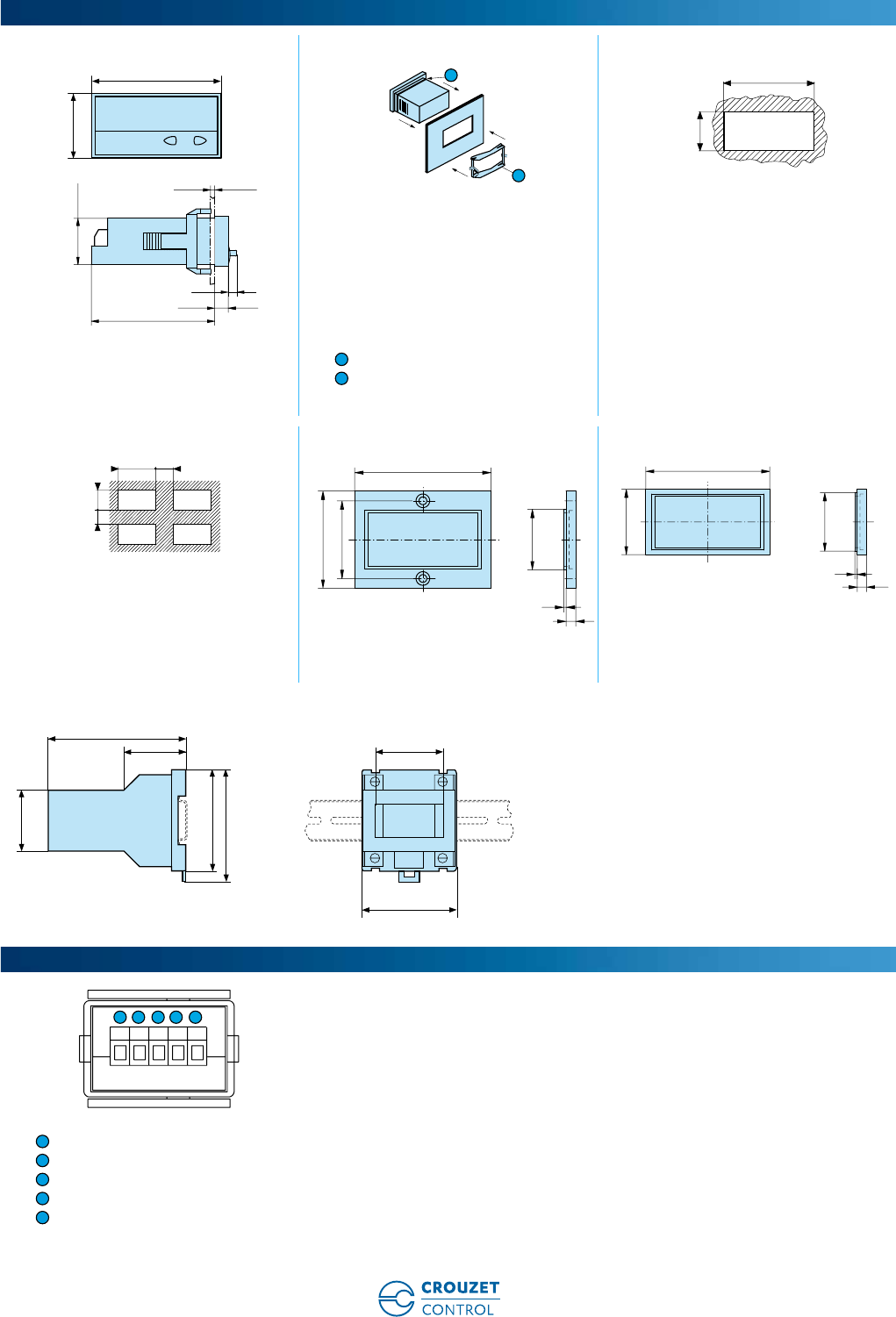
3
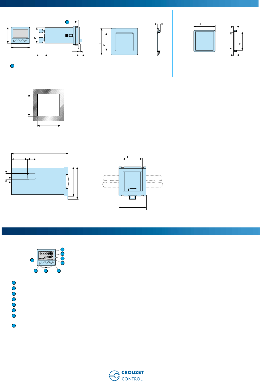
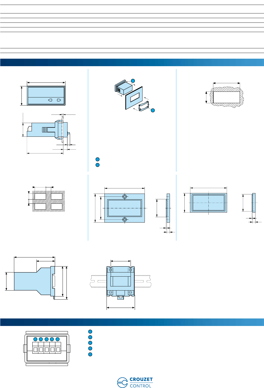
26546842 - Adaptor for 72 x 72 mm cut-out 26546846 - Adaptor for 55 x 55 mm cut-out
10.5 max.
Panel cut-out
26546841 - DIN rail adaptor
Display and buttons
Current value
Selected value
Chronometer display
Active output indication
Prog/mode button
Preset control buttons
Button required for programming
parameters
Shows which value is displayed
Dimensions (mm)
1
48
90,315,5
4,5
7
45
48
7,4
72
45,4
55
48,1
0
-0,2
0
+0,2
6
±0,1
7,4
±0,1
45,4
1
45
+0.6
0
45
+0.6
0
50
+0,5
0
41 22
145
15
75
83
5,5
70
Principles
3
4
5
7
8
1
2
6
1
2
3
4
5
6
7
8
www.crouzet-control.com 21
4
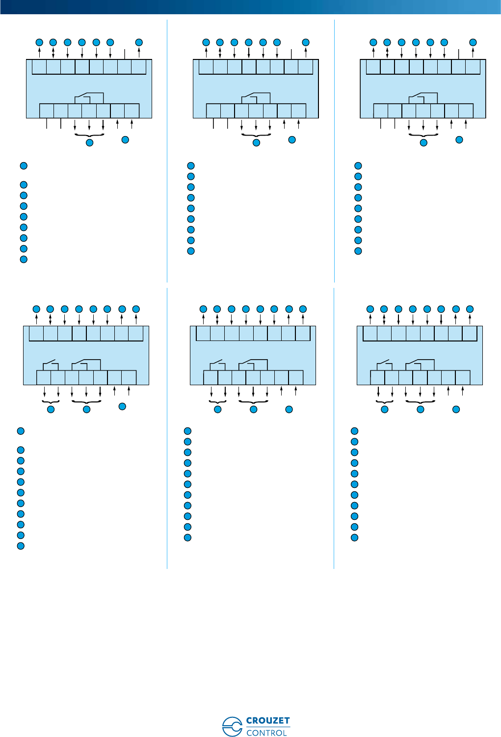
87621111 / 211 87621112 / 212 87621115 / 215
Sensor voltage supply (* UB
interconnected)
GND (0 Vc)
INP A (signal A input)
INP B (signal B input)
Reset (Reset input)
Gate input
Output 1 - 10-30 Vc/30 mA
11-12-13: Output 1
14-15: Supply
Output: 5 A/250 Va/AC: 24 Va
Sensor voltage supply
GND (0 Vc)
INP A (signal A input)
INP B (signal B input)
Reset (Reset input)
Gate input
Output 1 - 24 Vc/30 mA
11-12-13: Output 1
14-15: Supply
Output: 5 A/250 Va/AC: 24 Va
Sensor voltage supply
GND (0 Vc)
INP A (signal A input)
INP B (signal B input)
Reset (Reset input)
Gate input
Output 1 - 24 Vc/30 mA
11-12-13: Output 1
14-15: Supply
Output: 5 A/250 Va / AC: 24 Va
87621121 / 221 87621122 / 222 87621125 / 225
Sensor voltage supply (* UB
interconnected)
GND (0 Vc)
INP A (signal A input)
INP B (signal B input)
Reset (Reset input)
Gate input
Output 1: 10-30 Vc/30 mA
Output 2: 10-30 Vc/30 mA
9-10: Output 1
11-12-13: Output 2
14-15: Supply
Output: 5 A/250 Va / AC: 90 ➞260 Vc
Sensor voltage supply
GND (0 Vc)
INP A (signal A input)
INP B (signal B input)
Reset (Reset input)
Gate input
Output 1: 24 Vc/30 mA
Output 2: 24 Vc/30 mA
9-10: Output 1
11-12-13: Output 2
14-15: Supply
Output: 5 A/250 Va / AC: 90 ➞260 Vc
Sensor voltage supply
GND (0 Vc)
INP A (signal A input)
INP B (signal B input)
Reset (Reset input)
Gate input
Output 1: 24 Vc/30 mA
Output 2: 24 Vc/30 mA
9-10: Output 1
11-12-13: Output 2
14-15: Supply
Output: 5 A/250 Va / AC: 90 ➞260 Vc
Connections
13
123 45678
14 15109 11 12
5 6 71 2 3 4
89
NC
NC NC + -
13
123 45678
14 15109 11 12
5 6 71 2 3 4
89
NC
NC NC N~ L~
13
123 45678
14 15109 11 12
5 6 71 2 3 4
89
NC
NC NC N~ L~
1
2
3
4
5
6
7
8
9
1
2
3
4
5
6
7
8
9
1
2
3
4
5
6
7
8
9
13
123 45678
14 15109 11 12
5 6 871 2 3 4
10 11
+-
9
13
123 45678
14 15109 11 12
5 6 871 2 3 4
10 11
9
N~ L~
N~ L~
13
123 45678
14 15109 11 12
5 6 871 2 3 4
10 119
1
2
3
4
5
6
7
8
9
10
11
1
2
3
4
5
6
7
8
9
10
11
1
2
3
4
5
6
7
8
9
10
11
www.crouzet-control.com
22
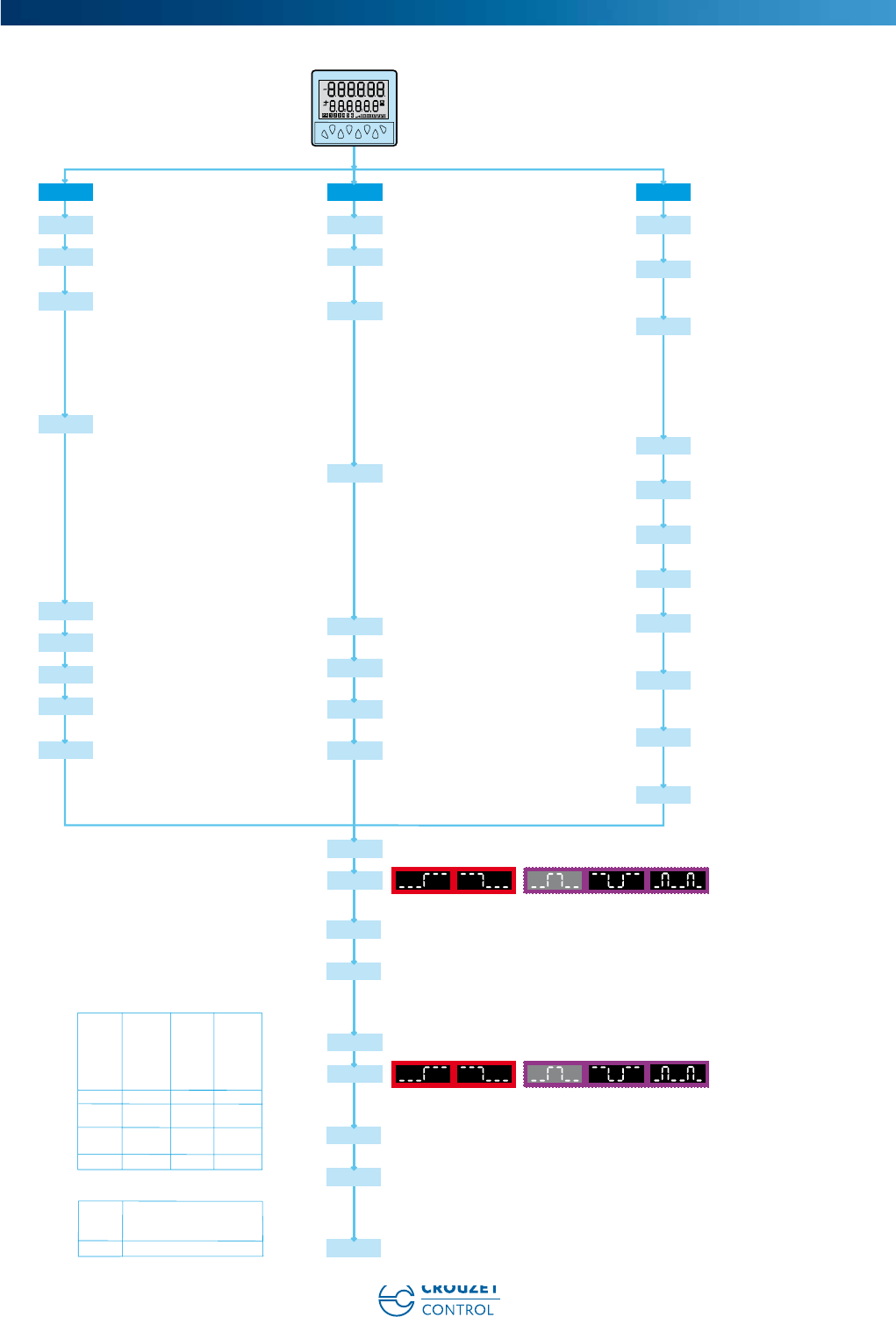
5
Programming diagram
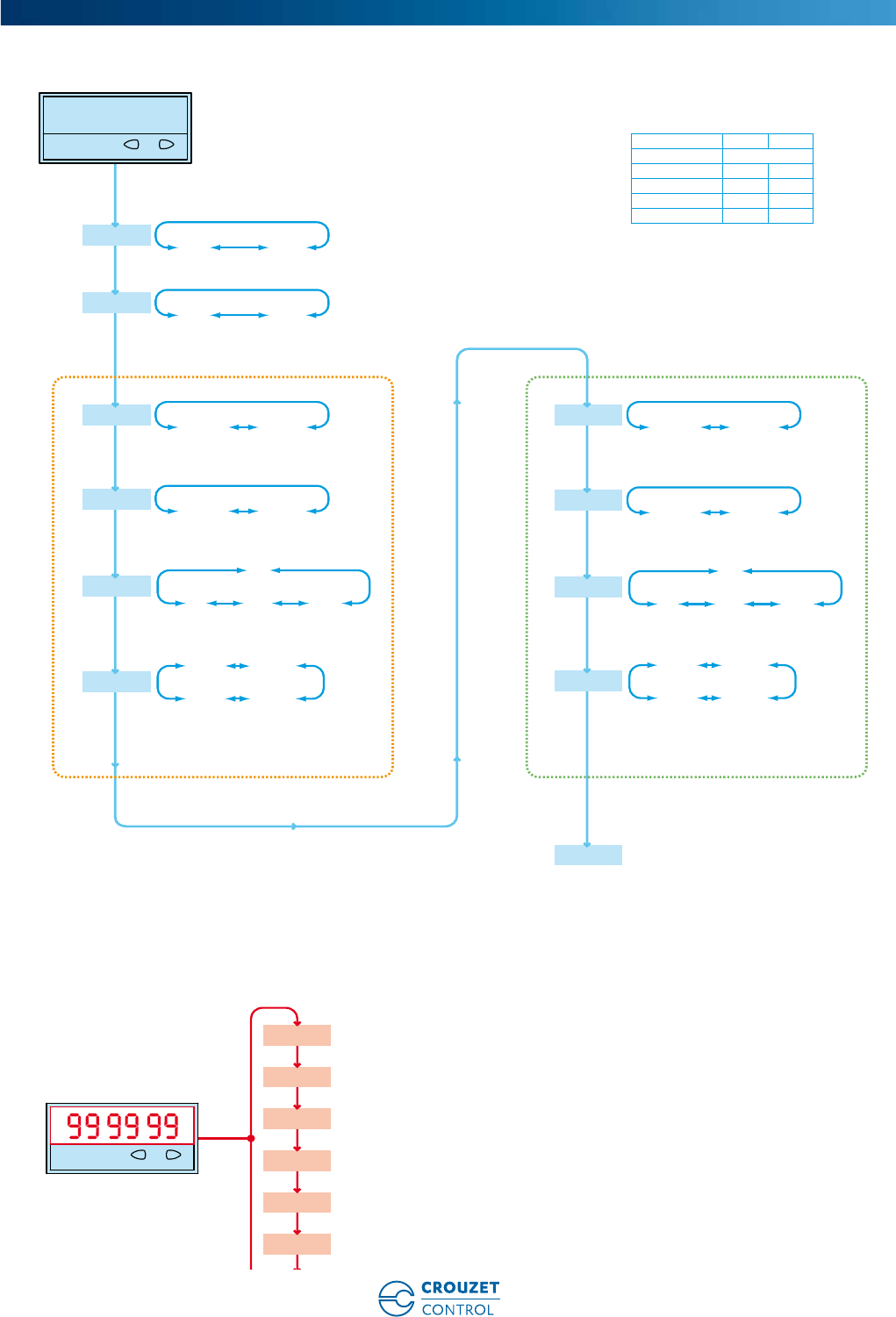
Applications
Cntr tiMErC tAcho
Input
PnP / npn
Input
PnP / npn
Input
PnP / npn
FrQ
HIGH / Low
Low=30Hz HIGH=max
StArt
tA.AS / tA.AA / tA.PP
tA.A
tA.AS
: Differential measurement A-B
tA.AA:Total measurement A+B
tA.PP
: Freq. Measurement with direction (phase)
tA.A
: Single frequency measurement
MultPI
00,0001...99,9999
diVidE
01,0000...99,9999
tUnit
U.MIN / U.SEC
dEcPt
0 / 0,0 / 0,00 / 0,000 / 0,0000 / 0,00000
Moving average
AVG
oFF / AVG2 / AVG5 / AVG 10 / AVG 20
Start delay
StuPtm
00.0..99,9
Waiting time
WAit0
00.0..99,9
Time signal output regulation
tiMES1
00.01..99,99s
**Only for multicolor version
CoLor**
rEd / rEdGm
FrQ
HIGH / Low
Low=30Hz HIGH=max
OutS1
on / oFF
StArt
tcCb / tcCab / tcCbb / tcSb
tcSbb / tcSab / tcAuto
tcCb
: Start/Stop pulse duration on input B (comulative)
tcCab
: Start edge to input A Stop edge to input B (comulative)
tcCbb
: Start edge to input B Stop edge to input B (comulative)
tcSb
: Start/Stop pulse duration on input B (single pulse)
tcSbb
: Start edge to input B Stop edge to input B (single pulse)
tcSab
: Start edge to input A Stop edge to input B (single pulse)
tcAuto
: Control timing of reset
tUnit
SEC / MIN / hour / h.Min.S /
rS0 / rSA0 / rSAP2 / bCrSA0 /
tCrSA0 / rSP2
rS0
: Count mode Add (reset to zero)
rSP2
: Count mode Sub (reset to main preset)
rSA0
: Count mode Add with automatic reset
rSAP2
: Count mode Sub with automatic reset
bCrSA0
: Count mode Add with automatic reset and batch counter
tCrSA0
: Count mode Add with automatic reset and total counter
Out.oP
dEcPt
0 / 0,0 / 0,00 / 0,000 / 0,0000 / 0,00000
CoLor
rEd / rEdGm
P1
Loc / UnLoc / Loc-tr
Loc
: Preset value is locked
UnLoc
: Preset value is open
UnLoc-tr
: Preset valure is locked is possible to open with pression key with 10s
P2
Loc / UnLoc / Loc-tr
Loc
: Preset value is locked
UnLoc
: Preset value is open
UnLoc-tr
: Preset valure is locked is possible to open with pression key with 10s
PrG
Loc / UnLoc
Loc
: Press Key R and P into 15s after powerOn to enter in the programming
UnLoc
: Press Key R and P for 3 sec to enter in the programming
norES
: No reset
ELrEs
: Electrical reset
ManrE
: Manual reset
ManEL
: Manual and electrical reset
rESMod
no rEs / ELrES / Man.rE / Man.EL
FrQ
HIGH / Low
Low=30Hz HIGH=max
In.Cnt
dir / AS / AA / PP / PP2 / PP4
dir
: Count direction
AS
: Differential counting A-B
AA
: Totalising A+B
PP
: Quadrature Input
PP2
: Quadrature with pulse doubling
PP4
: Quadrature x4
MultPI
00,0001...99,9999
MultPI
00,0001...99,9999
diVidE
01,0000...99,9999
dEcPt
0 / 0,0 / 0,00 / 0,000 / 0,0000 / 0,00000
**Only for multicolor version
CoLor**
rEd / rEdGm
norES
: No reset
ELrEs
: Electrical reset
ManrE
: Manual reset
ManEL
: Manual and electrical reset
rESMod
no rEs / ELrES / Man.rE / Man.EL
permanent signal timed signal
S1
Time signal output regulation
tiMES1
00.01..99,99s
**OutS2
on / oFF
rS0 / rSA0 / rSAP2 / bCrSA0 /
bCrSA2 / tCrSA0 / tCrSA2 /
bCrSo / bCrSP2 / tCrS0 / tCrSP2 / MurS0
rS0
: Count mode Add (reset to zero)
rSP2
: Count mode Sub (reset to main preset)
rSA0
: Count mode Add with automatic reset
rSAP2
: Count mode Sub with automatic reset
*bCrSA0
: Count mode Add with automatic reset and batch counter
*tCrSA0
: Count mode Add with automatic reset and total counter
MurS0
: Multitotalizer (reset to zero)
*Only version 2 preset
Out.oP
**Only version 2 preset
permanent signal timed signal
**S2
Counter
Output rSo / rSP2 rSA0 rSAP2
operation bCrS0 bCrSA0
modes bCrSP2 bCrSA2
tCrS0 tCrSA0
tCrSP2 tCrSA2
MurS0
dir 40 kHz 5.2 kHz 4.2 kHz
AS 20 kHz 4.4 kHz 4.2 kHz
AA
PP 20 kHz 2.2 kHz 2.1 kHz
PP2
PP4 15 kHz 1.1 kHz 1.0 kHz
tA.A
tA.AS 40 kHz
tA.AA
Quad 20 kHz
Tachometer
www.crouzet-control.com 23
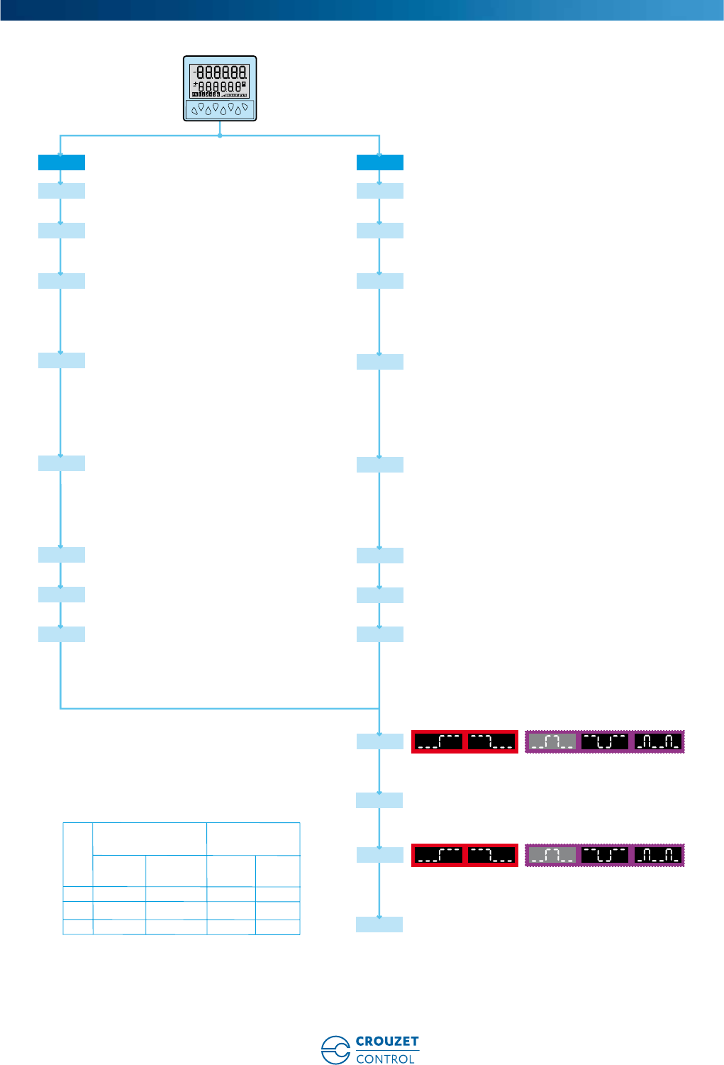
6
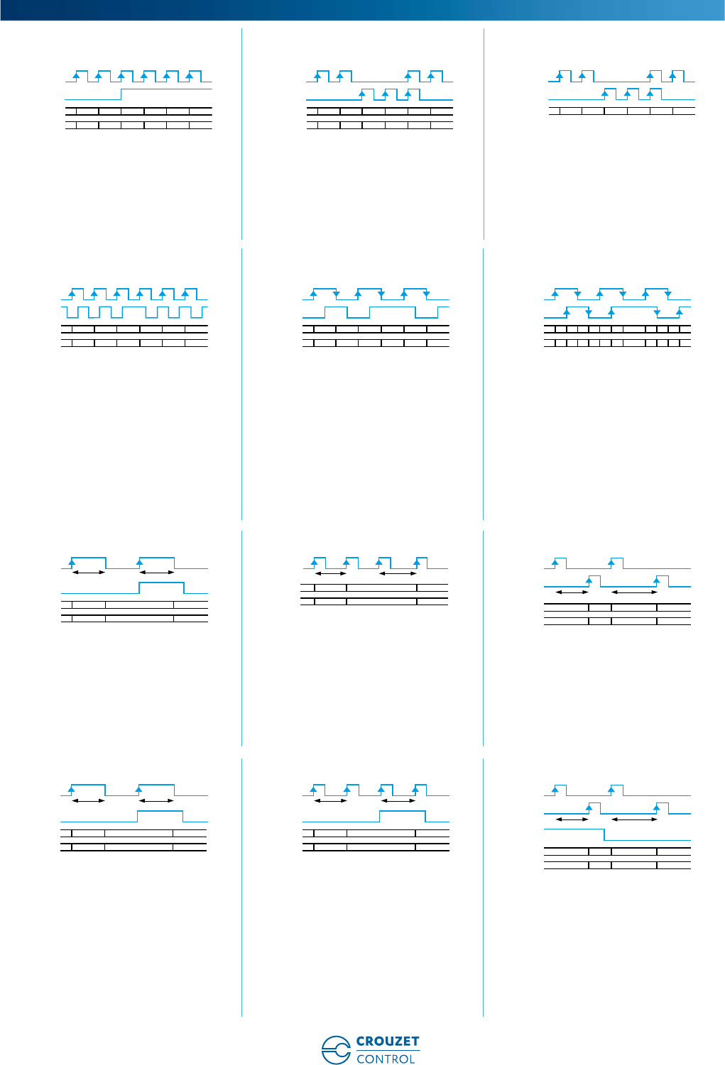
Counter: dir Counter: AS Counter: AA
Inp A: counter input
Inp B: count direction
rS0: Display 0 ➞Preset
rSP2: Display Preset ➞0
Inp A: Add. counter input 1
Inp B: sub. counter input 2
rS0: Display 0 ➞Preset
rSP2: Display Preset ➞0
Inp A: Add. counter input 1
Inp B: sub. counter input 2
rS0: Display 0 ➞Preset
Counter: PP Counter: PP2 Counter: PP4
A 90° B
Inp A: Counter input
Counting on an edge
Inp B: Reversal of direction
rS0: Display 0 ➞Preset
rSP2: Display Preset ➞0
A 90° B
Inp A: Counter input
Counting on a rising edge and on a
falling edge
Inp B: Reversal of direction
rS0: Display 0 ➞Preset
rSP2: Display Preset ➞0
A 90° B
Inp A: Counter input
Counting on a rising edge and on a
falling edge
Inp B: Counter input
Counting on a rising edge and on a
falling edge, reversal of direction
rS0: Display 0 ➞Preset
rSP2: Display Preset ➞0
Chronometer: Start tcCb Chronometer: Start tcCbb Chronometer: Start tcCAb
Inp A: No function
Inp B: On/Off
Cumulative time counting
Add: Display 0 ➞Preset
Sub: Display Preset ➞0
Inp A: No function
Inp B: On/Off
Cumulative time counting
Add: Display 0 ➞Preset
Sub: Display Preset ➞0
Inp A: On
Inp B: Off
Cumulative time counting
Add: Display 0 ➞Preset
Sub: Display Preset ➞0
Chronometer: Start tcSb Chronometer: Start tcSbb Chronometer: Start tcSAb
Inp A: No function
Inp B: On/Off
Individual time counting while B is
active, automatic reset before each
new count
Add: Display 0 ➞Preset
Sub: Display Preset ➞0
Inp A: No function
Inp B: On/Off
Individual time counting, automatic
reset before each new count
Add: Display 0 ➞Preset
Sub: Display Preset ➞0
Inp A: On
Inp B: Off
Individual time counting, automatic
reset before each new count
Add: Display 0 ➞Preset
Sub: Display Preset ➞0
Curves
INP A
dir
INP B
rS0
rSP2
10 0 -22 1 -1
P+1P P P-2P+2 P+1 P-1
INP A
AS
INP B
rS0
rSP2
10 0121 0
P+1P P P+1P+2 P+1 P
INP A
AA
INP B
rS0
10 4723 6
INP A
PP
INP B
rS0
rSP2
10 2023 1
P+1P P+2 PP+2 P+3 P+1
INP A
PP2
INP B
rS0
rSP2
10 4223 3
P+1P P+4 P+2P+2 P+3 P+3
INP A
PP4
INP B
rS0
rSP2
10 4 6 7 654323 5
P+1
P
P+4 P+5 P+6 P+7 P+4 P+3P+2 P+3 P+6 P+5
INP B
GATE
ADD
SUB
0...........
...........
T1
on offoff
T1 T2
P-T1
T1+T2
P-T1-T2
P
INP B
ADD
SUB
0...........
...........
T1
T1 T2
P-T1
T1+T2
P-T1-T2
P
INP B
INP A
ADD
SUB
0.....................
.....................
T1
T1 T2
P-T1
T1+T2
P-T1-T2
P
INP B
GATE
A
DD
SUB
0...........
...........
T1
on offoff
T1 T2
P-T1
T2
P-T2
P
GATE
A
DD
SUB
0...........
...........
T1
on offoff
T1 T2
P-T1
T2
P-T2
P
INP B
INP B
INP A
GATE
ADD
SUB
0.....................
.....................
T1
offon
T1 T2
P-T1
T2
P-T2
P
www.crouzet-control.com
24
7
Chronometer: Start tcAuto Tachometer: Start tA.A Tachometer: Start tA.AS
Inp A: No function
Inp B: No function
Time counting command via Reset
(manual or electrical)
Add: Display 0 ➞Preset
Sub: Display Preset ➞0
The Gate input has a display memory
function
Inp A: Frequency input
Inp B: No function
Inp A: Frequency input 1
Inp B: Frequency input 2
Formula: A - B
Tachometer: Start tA.AA Tachometer: Start tA.PP Output operation: OutoP rS0
Inp A: Frequency input 1
Inp B: Frequency input 2
Formula: A + B
A 90° B
Inp A: Frequency input 1
Inp B: Reversal of direction
Output operation: OutoP rSA0 Output operation: OutoP bCrSA0 Output operation: OutoP tCrSA0
Output operation: OutoP rSP2 Output operation: OutoP rSAP2 Output operation: OutoPbCrSA2
offoff on
T1 T2 T3 T4
ADD
SUB
0 T2T1 ..........
..........
.....
.....
0
P
.....
.....
0
P
.....
.....
0
PP
P-T2
T2 +T3
P-T2-T3P-T1
PRESET
RESET
GATE
INP A
Display
0F
A1
00F
A0
F
A2
0F
A2
xF
A0
F
A1
0
INP B
Display
0F
A0 -
F
B0 -
F
B2
0F
A0
F
A1 -
F
B1
0F
B1
x0F
B0
F
B2
INP A
0F
A2
xF
A0
F
A1
0
INP B
Display
0F
A0 +
F
B0
F
B2
0F
A0
F
A1 +
F
B1
0F
B1
x0F
B0
F
B2
INP A
0F
A2
xF
A0
F
A1
0
INP B
Display
0FA1 -FA40FA0 FA2 -FA3
INP A
fA0 fA1 fA2 fA3 fA4 fA5
RESET
PR2
PR1
COUNTER
OUT P1
OUT P2
RESET
PR2
PR1
COUNTER
OUT P1
OUT P2
RESET
PR2
PR1
BATCH
COUNTER
OUT P1
OUT P2
RESET
PR2
PR1
TOTAL
COUNTER
OUT P1
OUT P2
RESET
PR2
PR1
COUNTER
OUT P1
OUT P2
RESET
PR2
PR1
COUNTER
OUT P1
OUT P2
RESET
PR2
PR1
COUNTER
OUT P1
BATCH
OUT P2
www.crouzet-control.com 25
8
Output operation: OutoP tCrSA2 Output operation: OutoP bCrS0 Output operation: OutoP tCrS0
Output operation: OutoP MurS0 (AA) Output operation: OutoP bCrSP2 Output operation: OutoP tCrSP2
Output operation: OutoP MurS0 (AS)
RESET
PR2
TOTAL
PR1
COUNTER
OUT P1
OUT P2
0
RESET
PR2
PR1
COUNTER
OUT P1
BATCH
OUT P2
RESET
PR2
PR1
COUNTER
OUT P1
TOTAL
OUT P2
RESET Inp.
RESET Man.
PR1
AB
COUNTER A
OUT P1
COUNTER B
PR2
OUT P2
COUNTER A+B
RESET
PR2
COUNTER
PR1
OUT P1
BATCH
OUT P2
RESET
PR2
TOTAL
PR1
COUNTER
OUT P1
OUT P2
RESET Inp.
RESET Man.
PR1
AB
COUNTER A
OUT P1
COUNTER B
PR2
OUT P2
COUNTER A+B
www.crouzet-control.com
26
1
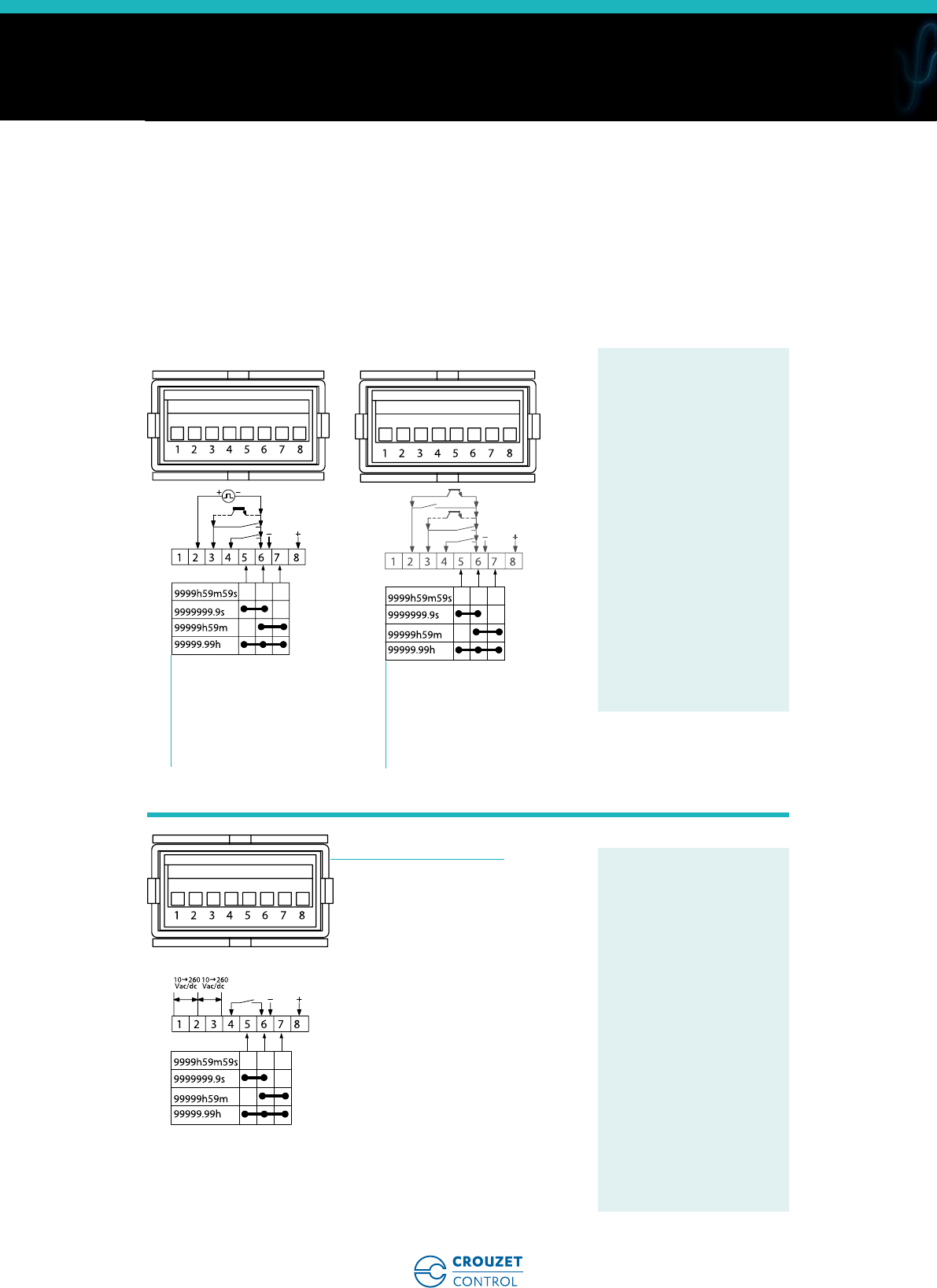
➜ Up counters/Down counters - 48 x 48 - CTR48E "Essential"
■ Counter, Preselection chronometer
■ Maximum input frequency 5 k Hz
■ Simple parameter setting, configuration
using text menus
■ Easy modification of presets
■ Multiplication factor
■ 3 A changeover relay
■ Backlit LCD display (green) : 6 digits, height 9 mm
■ IP 65 sealed panel
■ Option of locking the keypad, completely or partially
(preset, programming)
■ Accessories for 72 x 72 or 55 x 55 cut-out,
DIN rail adaptor
Type Functions Preset Voltages Output Code
Green backlit
LCD display
Counter, Preselection chronometer 1 10 ➞30 Vc1 relay 87629111
Counter, Preselection chronometer 1 115 Va1 relay 87629113
Counter, Preselection chronometer 1 230 Va1 relay 87629114
Counter, Preselection chronometer 2 10 ➞30 Vc1 changeover relay,
1 NO relay
87629121
Counter, Preselection chronometer 2 115 Va1 changeover relay,
1 NO relay
87629123
Counter, Preselection chronometer 2 230 Va1 changeover relay,
1 NO relay
87629124
Description Code
Adaptor for 72 x 72 mm cut-out 26546842
Adaptor for 55 x 55 mm cut-out 26546846
DIN rail adaptor 26546841
Environmental characteristics
Supply 11 ➞30 Vc / 115 V a / 230 Va
Relative humidity (no condensation) EN 60068-2-30 40/93% RLF
Altitude 0 < 2000 m
Certifications CE
Vibration resistance in 3 axes 10-55 Hz/1 min/XYZ EN 60068-2-6: 30 min. in each direction
Connection by screw terminals Removable
Protection Conforming to standard EN 60529 IP65 for panel/IP20 for connections
Front panel watertight seal ✓
Temperature limits use (°C) -10 ➞+50
Temperature limits stored (°C) -25 ➞+75
Weight (g) 150 c version
250 a version
General characteristics
Reset to zero or to preset On panel: if not locked during programming
Electrical: automatic, voltage or solid state (NPN or PNP depending on
programming)
Minimum pulse time Impulse counter: < 15 ms
Chronometer: 500 µs
Option to protect against reset from front panel ✓
Scale factor (each input pulse is multiplied by this figure) 00.0001 ➞99.9999
Decimal point selectable for ease of reading 0
0.0
0.00
0.000
0.0000
0.00000
Sensor supply version a-40/+15% 50 mA 230 Va
-40/+15% 40 mA 115 Va
Programming and current value backed up via EEPROM memory ✓
Service life 10 years
Electronic multifunction counters with preselection
Part numbers
Accessories
General characteristics
www.crouzet-control.com 27
2
Operating characteristics
Functions Preselection counter, Chronometer
Number of presets 1 or 2
Display LCD with green backlighting
Height digits (mm) LCD 9
Display details - 999 999 ➞999 999
Input characteristics
Inputs 2 counter inputs
1 reset input, 1 locking input
Input modes Dir: Directional
AS: up/dn
PP: phase
Input type Voltage or solid state
High level 3.5 ➞30 Vc
Low level 0 ➞2 Vc
Relay output characteristics
Changeover relay ✓
NO contact Depending on version
Maximum current 3 A
Minimum current 30 mA
Maximum voltage 30 Vc / 250 Va
Min. voltage 5 Vz
Response time < 10 ms
Mechanical life (operations) 20 x 106
Number of operations 1 x 10⁵
Output modes: maintained or pulsed 0.01 ➞99.99 s
Panel cut-out 26546842 - Adaptor for 72 x 72 mm cut-out
10.5 max
26546846 - Adaptor for 55 x 55 mm cut-out
26546841 - DIN rail adaptor
Dimensions (mm)
1
48
90,315,5
4,5
7
45
48
45
+0.6
0
45
+0.6
0
7,4
72
45,4
1
55
48,1
0
-0,2
0
+0,2
6
±0,1
7,4
±0,1
45,4
50
+0,5
0
41 22
145
15
75
83
5,5
70
www.crouzet-control.com
28
3
87629111 87629113 / 114 87629121
Sensor voltage supply (* UB
interconnected)
GND (0 Vc)
INP A (signal A input)
INP B (signal B input)
Reset (Reset input)
Lock (locking switch input)
11-12-13: Output 1
14-15: Supply
Power supply - GND
Sensor voltage supply
GND (0 Vc)
INP A (signal A input)
INP B (signal B input)
Reset (Reset input)
Lock (locking switch input)
11-12-13: Output 1
14-15: Supply
Sensor voltage supply (* UB
interconnected)
GND (0 Vc)
INP A (signal A input)
INP B (signal B input)
Reset (Reset input)
Lock (locking switch input)
9-10: Output 1
11-12-13: Output 2
14-15: Supply
Power supply - GND
87629123 / 124
Sensor voltage supply
GND (0 Vc)
INP A (signal A input)
INP B (signal B input)
Reset (Reset input)
Lock (locking switch input)
9-10: Output 1
11-12-13: Output 2
14-15: Supply
Connections
13
123 45678
14 15109 11 12
5 61 2 3 4
7
89
NC NC
NC NC
13
123 45678
14 15109 11 12
5 61 2 3 4
7
NC NC
NC NC
8
N~ L~
13
123 45678
14 15109 11 12
5 61 2 3 4
8
910
NC NC
7
1
2
3
4
5
6
7
8
9
1
2
3
4
5
6
7
8
1
2
3
4
5
6
7
8
9
10
13
123 45678
14 15109 11 12
5 61 2 3 4
89
NC NC
N~ L~
7
1
2
3
4
5
6
7
8
9
www.crouzet-control.com 29
4
Programming diagram
Applications
Input
PnP / npn
Input
PnP / npn
Time signal output regulation
tiMES1
00.01..99,99s
FrQ
HIGH / Low
Low=30Hz HIGH=max
StArt
tcCab / tcCbb / FrErun
FrErun: Gate Mode (INPA)
tcCab: Start edge to input A Stop edge to input B (comulative)
tcCbb: Start edge to input B Stop edge to input B (comulative)
tUnit
SEC / MIN / hour / h.Min.S /
dEcPt
0 / 0,0 / 0,00 / 0,000 / 0,0000 / 0,00000
norES: No reset
ELrEs: Electrical reset
ManrE: Manual reset
ManEL: Manual and electrical reset
rESMod
no rEs / ELrES / Man.rE / Man.EL
FrQ
HIGH / Low
Low=30Hz HIGH=max
In.Cnt
dir / AS / PP
dir: Count direction
AS: Differential counting A-B
PP: Quadrature Input
Loc
ProG / PrESEt / PrgPrE
ProG: Programming us locked
PrESEt: Preset value us locked
PrgPrE: Preset and programming us locked
(The activation is with the electrical input LOCK)
(the choice is valid for P1 and P2 in the case of version to two pres.)
Loc
ProG / PrESEt / PrgPrE
ProG: Programming us locked
PrESEt: Preset value us locked
PrgPrE: Preset and programming us locked
(The activation is with the electrical input LOCK)
(the choice is valid for P1 and P2 in the case of version to two pres.)
MultPI
00,0001...99,9999
MultPI
00,0001...99,9999
dEcPt
0 / 0,0 / 0,00 / 0,000 / 0,0000 / 0,00000
norES: No reset
ELrEs: Electrical reset
ManrE: Manual reset
ManEL: Manual and electrical reset
rESMod
no rEs / ELrES / Man.rE / Man.EL
permanent signal timed signal
S1
Time signal output regulation
tiMES1
00.01..99,99s
rS0 / rSA0 / rSAP2 / rSP2
rS0: Count mode Add (reset to zero)
rSP2: Count mode Sub (reset to main preset)
rSA0: Count mode Add with automatic reset
rSAP2: Count mode Sub with automatic reset
Out.oP
rS0 / rSA0 / rSAP2 / rSP2
rS0: Count mode Add (reset to zero)
rSP2: Count mode Sub (reset to main preset)
rSA0: Count mode Add with automatic reset
rSAP2: Count mode Sub with automatic reset
Out.oP
**Only version 2 preset
permanent signal timed signal
**S2
Cntr tiMErC
Low : 1.0 V Low : 3.0 V
High : 4.0 V High : 30.0 V
rS0 rSA0 rS0 rSA0
rSP2 rSAP2 rSP2 rSAP2
dir 15 kHz 1.5 kHz 5 kHz 1.2 kHz
AS 10 kHz 1.5 kHz 5 kHz 1.2 kHz
PP 10 kHz 0.7 kHz 2.4 kHz 0.5 kHz
www.crouzet-control.com
30
5
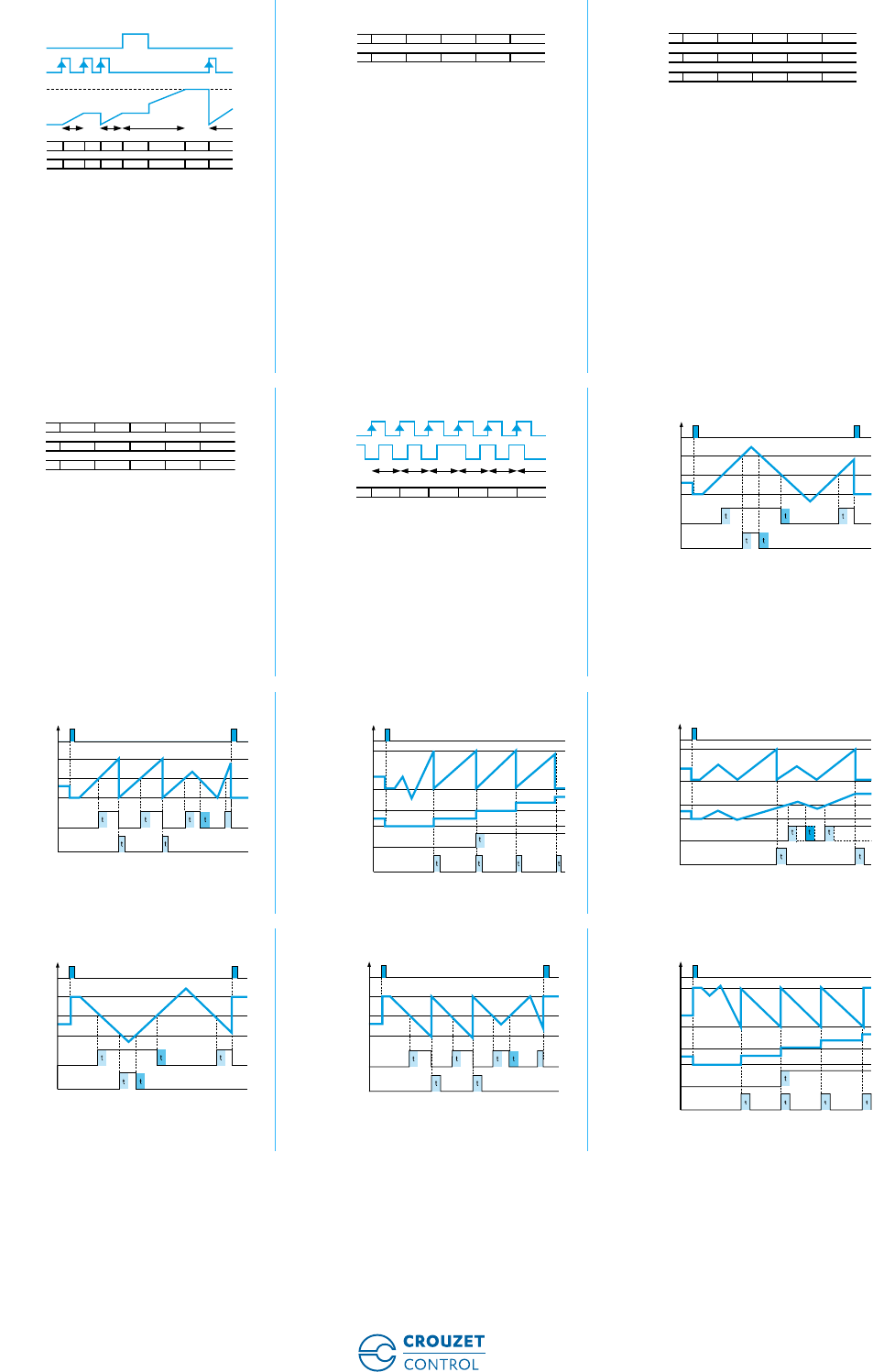
Counter: dir Counter: AS Counter: PP
A 90° B
Inp A: Counter input
Counting on an edge
Inp B: Reversal of direction
rS0: Display 0 ➞Preset
rSP2: Display Preset ➞0
Inp A: Add. counter input 1
Inp B: Sub. counter input 2
rS0: Display 0 ➞Preset
rSP2: Display Preset ➞0
A 90° B
Inp A: Counter input
Counting on an edge
Inp B: Reversal of direction
rS0: Display 0 ➞Preset
rSP2: Display Preset ➞0
Chronometer: Start tcCAb Chronometer: Start tcCbb Chronometer: Start FrErun
Inp A: On
Inp B: Off
Add: Display 0 ➞Preset
Sub: Display Preset ➞0
Inp A: No function
Inp B: On/Off
RS0/RSP2
Add: Display 0 ➞Preset
Sub: Display Preset ➞0
InpA: Gate
Time measurement via InpA
InpB: No function
Output operation 1: rS0 Output operation 1: rSA0 Output operation 1: rSP2
Output operation 1: rSAP2 Output operation 2: rS0 Output operation 2: rSA0
Output operation 2: rSP2 Output operation 2: rSAP2
Curves
INP A
dir
INP B
rS0
rSP2
10 0 -22 1 -1
P+1P P P-2P+2 P+1 P-1
INP A
AS
INP B
rS0
rSP2
10 0121 0
P+1P P P+1P+2 P+1 P
INP A
PP
INP B
rS0
rSP2
1
0 20
23 1
P+1P P+2 PP+2 P+3 P+1
INP B
INP A
ADD
SUB
0.....................
.....................
T1
T1 T2
P-T1
T1+T2
P-T1-T2
P
INP B
ADD
SUB
0...........
...........
T1
T1 T2
P-T1
T1+T2
P-T1-T2
P
INP A
(GATE)
ADD
SUB
0...........
...........
...........
...........
T1
active active
T1 T2
P-T1
T1+T2
P-T1-T2
P
RESET
S1
COUNTER
OUT S1
RESET
S1
COUNTER
OUT S1
RESET
S1
COUNTER
OUT S2
RESET
S1
COUNTER
OUT S2
RESET
S2
PR1-PR3-PR4
COUNTER
OUT P1-P3-P4
OUT S2
RESET
S2
PR1-PR3-PR4
COUNTER
OUT P1-P3-P4
OUT S2
RESET
S2
PR1-PR3-PR4
COUNTER
OUT P1-P3-P4
OUT S2
RESET
S2
PR1-PR3-PR4
COUNTER
OUT P1-P3-P4
OUT S2

www.crouzet-control.com 31
To order:
Customer Service
Crouzet Control
Tel.: +33 (0) 475 802 102
customer.relation@crouzet.com
Crouzet Control,
Technology and expertise,
behind every project
• Local support for all industrial projects.
• A multi-skilled team.
• A sales presence in over 40 countries.
• A Premium offer designed to ensure the excellence of products and services.
• Eco-design integrated in Crouzet's Offer Creation Process.
• Certifications: ISO 9001, ISO 14001, OHSAS 18001.
• Products which comply with international standards (UL, CSA, EC).
• A dynamic R&D department.
In addition to this catalogue, the www.crouzet-control.com
website offers the latest tools, available as free downloads,
including M3 Soft software, technical data sheets for each
product and installation manuals.
www.crouzet-control.com
32
1
➜ Multifunction counter - LED 24 x 48 - CTR24L
■ High brightness display: 6-digit LED, height 8 mm
■ Maximum input frequency 50 k Hz
■ Programmable multifunction: Counter/Tachometer/
Chronometer
■ Reset on panel or external with inhibition option
■ Supply: 10 ➞30 Vc
■ Easy to program
■ Scaling factor (Counter - Tachometer)
■ Decimal point (Counter - Tachometer)
■ Timing range 0.001 s ➞999.999 hrs (Chronometer)
■ Impulses or time measured in hrs/min/sec and in real
time (Chronometer)
■ Accessories for 50 x 25 mm cut-out
Type Functions Code
CTR24L - 2511 Counter, Tachometer, Chronometer 87623570
Description Code
Adaptor for 50 x 25 mm cut-out - Fixed with screws 26546843
Adaptor for 50 x 25 mm cut-out - Fixed with clips 26546844
DIN rail adaptor 26546840
Clip-fixing kit (supplied with the product) 26546848
Environmental characteristics
Consumption 10 ➞30 Vc max 55 mA with protection against polarity reversal
Connection by 5 screw terminals at rear of casing ✓
Connection capacity 1.5 mm2
Fixed using bracket ✓
Degree of protection front face IP 65
Data memory EEPROM
Temperature limits use (°C) -20 ➞+55
Temperature limits stored (°C) -25 ➞+70
Dielectric strength According to EN 61010-1: 2000 V/50 Hz/1 min
Conformity to standards EN 61000-6-2 - EN 55011 class B
Altitude 2000 m
Certifications UL - cULus (pending) - CE
Weight (g) 50
Operating characteristics
Functions Impulse counter, Tachometer, Chronometer
Display 6-digit LED
Height digits (mm) 8
Input characteristics
Inputs 2 counter inputs, 1 reset input
High level 0 ➞0.2 x Ub Vc
Low level 0.6 x Ub ➞30 Vc
Cyclical ratio Any (maximum frequency given for a cyclical ratio = 1/1)
Schmitt trigger input
Polarity NPN or PNP for all inputs (programming)
Minimum impulse duration for reset 5 ms
Frequency of filtered input Filter active: 30 Hz
Filter disabled: maximum frequency (programming)
Input impedance (kΩ) Appr. 5
Impulse counter
Display details - 19 999 ➞999 999
Elimination of non-significant zeros ✓
Electronic multifunction counters without preselection
Part numbers
Accessories
General characteristics
www.crouzet-control.com 33
2
Counting input modes Cnt.Dir ➞Counter input INPA and counter direction input INPB
Up.dn ➞INPA INPB differential counting
Up.up ➞Sum of INPA + INPB
QuAd ➞Phase discriminator
QuAd2 ➞Phase discriminator with doubling of impulses
QuAd4 ➞Phase discriminator with quadrupling of impulses
Inputs INPA / INPB Dynamic
Reset input (terminal 5) Dynamic Reset input connected in parallel with the red SET/RESET button
Sets the counter to the defined preset value
Reset to zero - Panel If not locked during programming
Remise à zéro - Externe (borne 5) If not locked during programming
Scale factor 1 ➞99.9999
Scaling factor 1 ➞99.9999
Decimal point 0
0.0
0.00
0.000
Maximum counting frequency CntDir ➞50 kHz
UpDown ➞25 kHz
UpUp ➞25 kHz
Quad1 ➞25 kHz
Quad2 ➞25 kHz
Quad4 ➞15 kHz
Tachometer
Display details 0 ➞999 999
Elimination of non-significant zeros ✓
Conversion time 1/s ou 1/min
Input INPA Dynamic
Accuracy < 0.1%
Measurement principle < 38 Hz: measurement of period duration
> 38 Hz: measurement with duration time base = 26.3 ms
Scale factor 1 ➞99.9999
Scaling factor 1 ➞99.9999
Decimal point 0
0.0
0.00
0.000
Maximum counting frequency 50 kHz
Chronometer
Display details 0.001 s ➞999 999 h
Elimination of non-significant zeros ✓
Functions GatE.Lo ➞Time measurement if INPB is not active
GatE.hi ➞Time measurement if INPB is active
Inb.Inb ➞Time measurement on/off via the INPB edge
InA.Inb ➞Measurement on via the INPA edge, measurement off via the
INPB edge
Input INPA Start
Input INPB Start/Stop or Gate (depends on the input mode chosen)
Remise à zéro - Externe (borne 5) If not locked during programming
Reset input (terminal 5) Dynamic Reset input connected in parallel with the red SET/RESET button
Sets the counter to the defined preset value
Reset to zero - Panel If not locked during programming
Accuracy < 50
Decimal point 0
0.0
0.00
0.000
Time ranges 0.001 s ➞999 999 s
0.001 min ➞99 999 min
0.001 h ➞999 999 h
00 h 00 min 01 s ➞99 h 59 min 59 s
www.crouzet-control.com
34
3
CTR24L - 2511 Fixing strip with clip-on yoke Panel cut-out
Seal
Fixing yoke
4 appliances 26546843 - Adaptor for 50 x 25 mm cut-out -
Fixed with screws
26546844 - Adaptor for 50 x 25 mm cut-out -
Fixed with clips
Accessory supplied with the counter
26546840 - DIN rail adaptor
Supply: 10 ➞30 Vc
Supply: GND (0 Vc)
INPA
INPB (NC in tachometer mode)
SET/RESET (NC in tachometer mode)
Dimensions (mm)
24
22x45
48
6,5
4
19,3
59
CT R2 4L
2
1
22,2
- 0
+0,3
45
+0,6
1
2
+ 0,3
+ 0,6
3045
20 22,2
56
25X50
40
32
4
1
53
28
25X50
4
1
50,4 x 25,4
70
101
45
75
83
45
Connections
1 2 3 4 5
1
2
3
4
5
www.crouzet-control.com 35
4
Programming diagram
Applications
Count tAcho
ModE
timEr
InPol
PnP nPn
Multiplying factor
FActor
01.0000 99.9999
Multiplying factor
FActor
01.0000 99.9999
Dividing factor
diUiSo
01.0000 99.9999
EndPro
EndPro
EndPro
The device will be set to the set point by pressing
the red key or activating the set/reset input
SEtPt
000000 999999
The device will be set to the set point
by pressing the red key or activating
the set/reset input
SEtPt
000000 999999
FiltEr
Filter on 30Hz – off Fmax
oFF on
InPol
PnP nPn
FiltEr
Filter on 30Hz – off Fmax
oFF on
InPol
PnP nPn
FiltEr
Filter on 30Hz – off Fmax
oFF on
InPut
Cnt.Dir:
Count input INPA +count direction INPB
Up.dn:
Differential count INPA – INPB
Up.up:
Totalising INPA + INPB
QuAd :
Count Up/Down INPA 90° INPBx1
QuAd2:
Count Up/Down INPA 90° INPBx2
QuAd4:
Count Up/Down INPA 90° INPBx4
Cntdir uP.dn uP.uP
QuAd QuAd2 QuAd4
rESet
ManEl:
manual reset red Key and electrical reset
norES:
no reset
ElrES:
only electrical reset
MAnrE:
manual reset
MAnEl norES
ELrES MAnrE
rESet
ManEl:
manual reset red Key and electrical reset
norES:
no reset
ElrES:
only electrical reset
MAnrE:
manual reset
MAnEl norES
ELrES MAnrE
tMode
Time units:
s/h/min
(accurancy depending on position
of the decimal point)
h.m.s
(decimal point setting is ignored)
SEC MIn
hour h.Min.s
StArt
GatE.Lo:
Counting while INPB is inactive
GatE.hi:
Counting while INPB is active
Inb.Inb:
Count Start/Stop whit INPB edge
InA.Inb:
Count Start whit INPA edge,
count Stop with INPB edge
GatE.Lo GatE.hI
Inb.Inb InA.Inb
dP
Decimal point
0.0 0.00 0.000
0
Dividing factor
diUiSo
01.0000 99.9999
dP
Decimal point
0.0 0.00 0.000
0
dP
Decimal point
0.0 0.00 0.000
0
SEC-1 MIn-1
diSPn
SEC-1:
Value conversion and display in 1/s
Min-1:
Value conversion and display in 1/m
00.1 99.9
Wait0
Max time to wait 00.1…..99.9s
Count frequency:
2511
DC power supply 24V 12V
Input level Standard
typ. low 2.5V 2.0V
typ. High 22.0V 10V
Fmax* kHz kHz
CntDir 50 20
UpDown 25 15
Up.up 25 15
Quad1 25 15
Quad2 25 15
Quad4 15 15
Count frequency:
DC power supply 24V 12V
Input level Standard
typ.low 2.5V 2.0V
typ. Hight 22.0V 10V
Fmax* kHz kHz
Tacho 50 20
Counting ranges:
Seconds 0,001s...999 999s
Minutes 0,001min...999 999min
Hours 0,001h...999 999h
h.min.s 00h00min01s...99h59min59s
CT R24L

www.crouzet-control.com
36
1
➜ Multifunction counter with 2 totalizers - LED 24 x 48 - CTR24L
■ High brightness display: 6-digit LED, height 8 mm
■ Maximum input frequency 25 k Hz
■ Counter with 2 separate totalizers, each with a
dedicated input
■ Reset on panel or external with inhibition option
■ Supply: 10 ➞30 Vc
■ Easy to program
■ Scaling factor
■ Decimal point
■ Accessories for 50 x 25 mm cut-out
Type Functions Code
CTR24L - 2512 Counter with 2 separate totalizers 87623571
Description Code
Adaptor for 50 x 25 mm cut-out - Fixed with screws 26546843
Adaptor for 50 x 25 mm cut-out - Fixed with clips 26546844
DIN rail adaptor 26546840
Clip-fixing kit (supplied with the product) 26546848
Environmental characteristics
Consumption 10 ➞30 Vc max 55 mA with protection against polarity reversal
Connection by 5 screw terminals at rear of casing ✓
Terminal capacity 1.5 mm2
Fixed using bracket ✓
Degree of protection front face IP 65
Data memory EEPROM
Temperature limits use (°C) -20 ➞+55
Temperature limits stored (°C) -20 ➞+55
Breakdown voltage EN 61010-1: 2000 V / 50 Hz / 1 min
Conformity to standards EN 61000-6-2 - EN 55011 class B
Altitude 2000 m
Certifications UL - cULus (pending) - CE
Weight (g) 50
Operating characteristics
Functions Counter with 2 separate totalizers
Display 6-digit LED
Height digits (mm) 8
Input characteristics
Inputs 2 counter inputs, 1 reset input
Low level 0 ➞0.2 x Ub Vc
High level 0.6 x Ub ➞30 Vc
Cyclical ratio Any (maximum frequency given for a cyclical ratio = 1/1)
Schmitt trigger input
Polarity NPN or PNP for all inputs (programming)
Minimum impulse duration for reset 5 ms
Frequency of filtered input Filter active: 30 Hz
Filter disabled: maximum frequency (programming)
Input impedance (kΩ) Appr. 5
Impulse counter
Display details 0 ➞999 999
Display When the buttons are pressed, the counter displays the following values:
CntA ➞Value of counter A (INPA input)
CntB ➞Value of counter B (INPB input)
Asubb ➞Difference between A-B (INPA-INPB input)
Aaddb ➞Addition of A+B (INPA+INPB input)
AdIUb ➞Division of A/B (INPA/INPB input)
Aprocb ➞Percentage (A-B) /A ( (INPA-INPB) /INPA input)
Elimination of non-significant zeros ✓
Counting input modes CntA ➞INPA input counting
CntB ➞INPB input counting
Electronic multifunction counters without preselection
Part numbers
Accessories
General characteristics
www.crouzet-control.com 37
2
Inputs INPA / INPB Dynamic
Reset input (terminal 5) Dynamic Reset input connected in parallel with the red SET/RESET button
Sets the counter to the defined preset value - possible on both totalizers
Reset to zero - Panel If not locked during programming
Reset to zero - External (borne 5) If not locked during programming
Scale factor 1 ➞99.9999 (separate for A and B)
Scaling factor 1 ➞99.9999 (separate for A and B)
Decimal point 0
0.0
0.00
0.000
Maximum counting frequency 25 k Hz
CTR24L - 2512 Fixing strip with clip-on yoke Panel cut-out
Seal
Fixing yoke
4 appliances 26546843 - Adaptor for 50 x 25 mm cut-out -
Fixed with screws
26546844 - Adaptor for 50 x 25 mm cut-out -
Fixed with clips
Accessory supplied with the counter
26546840 - DIN rail adaptor
Supply: 10 ➞30 Vc
Supply: GND (0 Vc)
INPA
INPB
SET/RESET
Dimensions (mm)
24
22x45
48
6,5
4
19,3
59
CT R2 4L
2
1
22,2
- 0
+0,3
45
+0,6
1
2
+ 0,3
+ 0,6
3045
20 22,2
56
25X50
40
32
4
1
53
28
25X50
4
1
50,4 x 25,4
70
101
45
75
83
45
Connections
1 2 3 4 5
1
2
3
4
5
www.crouzet-control.com
38
3
Programming diagram
Applications
2512
Counter A Counter B
InPol PnP nPn
FiltEr
Filter on 30Hz – off Fmax
Multiplying factor
FAcCnA 01.0000 99.9999
Multiplying factor
FAcCnb 01.0000 99.9999
Dividing factor
diVCnA 01.0000 99.9999
Value of counter A (Input INPA)
Pressing the right key
displays successively the
following varius values
Value of counter B (Input INPB)
CntB
Asubb
: Difference A-B (input INPA-INPB)
Asubb
Aaddb
: Sum A+B (Input INPA+INPB)
Aaddb
AdIUb
: Quotient A/B (Input INPA/INPB)
AdlUb
Aprocb
: Percentage (A-B)/A ( Input (INPA-INPB)/INPA )
Aprocb
EndPro
oFF on
reSCnA
SELECTION OF THE DISPLAYED VALUE
ManEl:
manual reset red Key and electrical reset
norES:
no reset
ElrES:
only electrical reset
MAnrE:
manual reset
CntA
MAnEl norES
ELrES MAnrE reSCnb
ManEl:
manual reset red Key and electrical reset
norES:
no reset
ElrES:
only electrical reset
MAnrE:
manual reset
MAnEl norES
ELrES MAnrE
dPCnA
Decimal point
0.0 0.00 0.000
0
Dividing factor
diVCnb 01.0000 99.9999
dPCnb
Decimal point
0.0 0.00 0.000
0
Count frequency:
DC power supply 24V 12V
Input level Standard
typ. low level 2.5V 2.0V
typ. high level 22.0V 10V
Fmax* kHz kHz
tot.tot 25 15
CT R24L
CT R24L

www.crouzet-control.com 39
To order:
Customer Service
Crouzet Control
Tel.: +33 (0) 475 802 102
customer.relation@crouzet.com
Crouzet Control,
Technology and expertise,
behind every project
• Local support for all industrial projects.
• A multi-skilled team.
• A sales presence in over 40 countries.
• A Premium offer designed to ensure the excellence of products and services.
• Eco-design integrated in Crouzet's Offer Creation Process.
• Certifications: ISO 9001, ISO 14001, OHSAS 18001.
• Products which comply with international standards (UL, CSA, EC).
• A dynamic R&D department.
In addition to this catalogue, the www.crouzet-control.com
website offers the latest tools, available as free downloads,
including M3 Soft software, technical data sheets for each
product and installation manuals.
www.crouzet-control.com
40
1
➜ Multifunction counter combining a totalizer and tachometer - LED 24 x 48 - CTR24L
■ High brightness display: 6-digit LED, height 8 mm
■ Maximum input frequency 30 k Hz
■ Combined function: Position indicator counter and
Tachometer
■ Reset on panel
■ Supply: 10 ➞30 Vc
■ Easy to program
■ Scaling factor (Counter - Tachometer)
■ Decimal point (Counter - Tachometer)
■ Accessories for 50 x 25 mm cut-out
Type Functions Code
CTR24L - 2513 Combined: Counter and Tachometer 87623572
Description Code
Adaptor for 50 x 25 mm cut-out - Fixed with screws 26546843
Adaptor for 50 x 25 mm cut-out - Fixed with clips 26546844
DIN rail adaptor 26546840
Clip-fixing kit (supplied with the product) 26546848
Environmental characteristics
Consumption 10 ➞30 Vc max 55 mA with protection against polarity reversal
Connection by 5 screw terminals at rear of casing ✓
Terminal capacity 1.5 mm2
Fixed using bracket ✓
Degree of protection front face IP 65
Data memory EEPROM
Temperature limits use (°C) -20 ➞+55
Temperature limits stored (°C) -25 ➞+70
Breakdown voltage According to EN 61010-1: 2000 V / 50 Hz / 1 min
Conformity to standards EN 61000-6-2 - EN 55011 class B
Altitude 2000 m
Certifications UL - cULus (pending) - CE
Weight (g) 50
Operating characteristics
Functions Impulse counter and Tachometer
Display 6-digit LED
Height digits (mm) 8
Input characteristics
Inputs 2 counter inputs, 1 tachometer input, 1 reset input
Low level 0 ➞0.2 x Ub Vc
High level 0.6 x Ub ➞30 Vc
Cyclical ratio Any (maximum frequency given for a cyclical ratio = 1/1)
Schmitt trigger input
Polarity NPN or PNP for all inputs (programming)
Minimum impulse duration for reset 5 ms
Frequency of filtered input Filter active: 30 Hz
Filter disabled: maximum frequency (programming)
Input impedance (kΩ) Appr. 5
Impulse counter
Display details - 19 999 ➞999 999
Elimination of non-significant zeros ✓
Counting input modes Cnt.Dir ➞Counter input INPA and counter direction input INPB
Up.dn ➞INPA INPB differential counting
Up.up ➞Sum of INPA + INPB
QuAd ➞Phase discriminator
QuAd2 ➞Phase discriminator with doubling of impulses
QuAd4 ➞Phase discriminator with quadrupling of impulses
Inputs INPA / INPB Dynamic
Reset to zero - Panel If not locked during programming
Electronic multifunction counters without preselection
Part numbers
Accessories
General characteristics
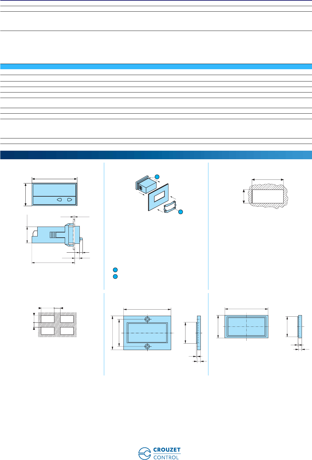
www.crouzet-control.com 41
2
Scale factor 1 ➞99.9999
Scaling factor 1 ➞99.9999
Decimal point 0
0.0
0.00
0.000
Maximum counting frequency Combined Counter + Tachometer functions:
CntDir ➞30 kHz
UpDown ➞10 kHz
UpUp ➞10 kHz
Quad1 ➞15 kHz
Quad2 ➞15 kHz
Quad4 ➞10 kHz
Tachometer
Display details 0 ➞999 999
Elimination of non-significant zeros ✓
Conversion time 1/s or 1/min
Input INPC Dynamic
Accuracy < 0.1%
Measurement principle < 38 Hz: measurement of period duration
> 38 Hz: measurement with duration time base = 26.3 ms
Scale factor 1 ➞99.9999
Scaling factor 1 ➞99.9999
Decimal point 0
0.0
0.00
0.000
Maximum counting frequency 30 kHz
CTR24L - 2513 Fixing strip with clip-on yoke Panel cut-out
Seal
Fixing yoke
4 appliances 26546843 - Adaptor for 50 x 25 mm cut-out -
Fixed with screws
26546844 - Adaptor for 50 x 25 mm cut-out -
Fixed with clips
Accessory supplied with the counter
Dimensions (mm)
24
22x45
48
6,5
4
19,3
59
CT R2 4L
2
1
22,2
- 0
+0,3
45
+0,6
1
2
+ 0,3
+ 0,6
3045
20 22,2
56
25X50
40
32
4
1
53
28
25X50
4
1
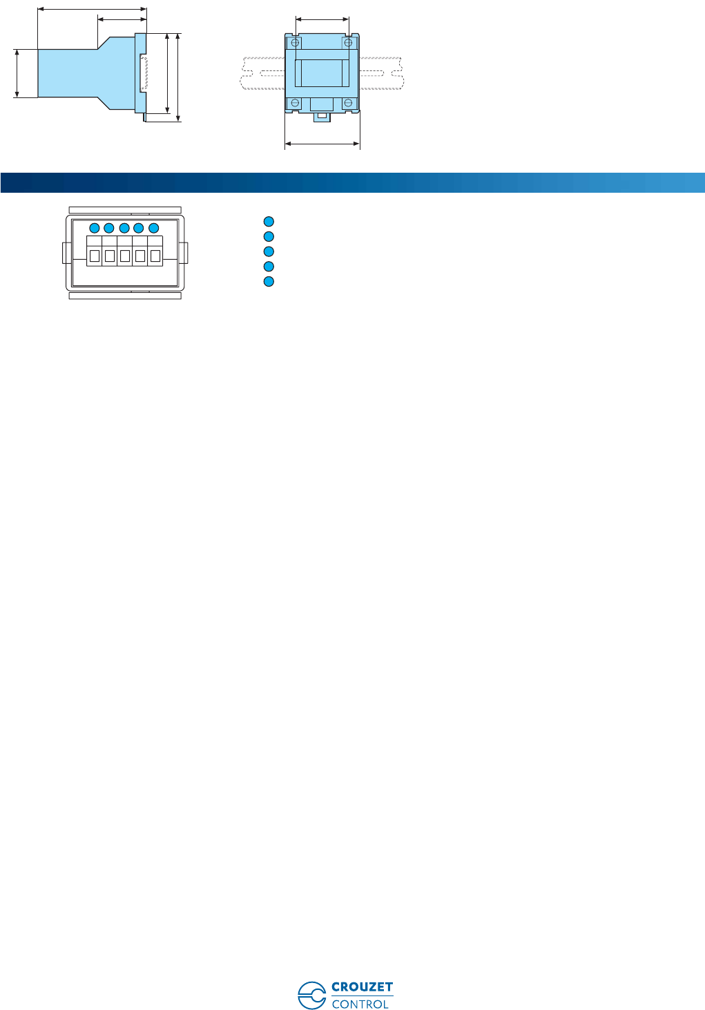
www.crouzet-control.com
42
3
26546840 - DIN rail adaptor
Supply: 10 ➞30 Vc
Supply: GND (0 Vc)
INPA (Counter)
INPB (Counter)
INPC (Tachometer)
50,4 x 25,4
70
101
45
75
83
45
Connections
1 2 3 4 5
1
2
3
4
5
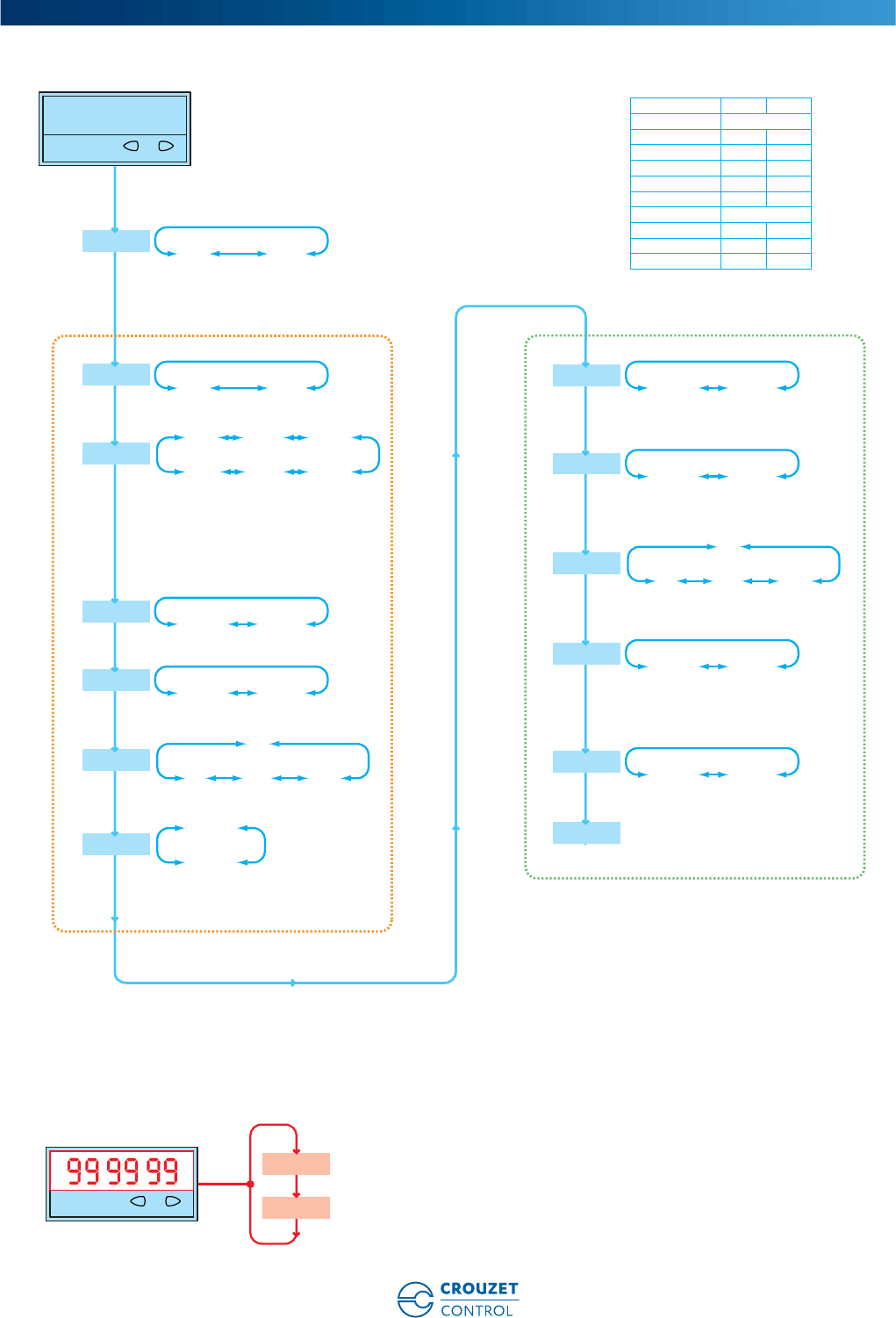
www.crouzet-control.com 43
4
Programming diagram
Applications
2513
Counter Tachometers
InPol
PnP nPn
Multiplying factor
FAc.Cnt
01.0000 99.9999
Dividing factor
diV.Cnt
01.0000 99.9999
Counter (position indicator)
Pressing the right key
displays successively the
following varius values
Tachometers
tAcho
EndPro
FiltEr
Filter on 30Hz – off Fmax
oFF on
SELECTION OF THE DISPLAYED VALUE
Count
reS.Cnt
ManE: manual reset red Key
norES: no reset (red key locked)
norES
MAnrE
dP.Cnt
Decimal point
0.0 0.00 0.000
0
DC power supply 24V 12V
Input level Standard
typ. low level 2.5V 2.0V
typ. high level 22.0V 10V
Fmax* kHz kHz
CntDir/Tacho 30 10
UpDown/Tacho 10 10
Up.up/Tacho 10 10
Quad1/Tacho 15 10
Quad2/Tacho 15 10
Quad4/Tacho 10 8
InPut
Cnt.Dir: Count input INPA +count direction INPB
Up.dn: Differential count INPA – INPB
Up.up: Totalising INPA + INPB
QuAd : Count Up/Down INPA 90° INPBx1
QuAd2: Count Up/Down INPA 90° INPBx2
QuAd4: Count Up/Down INPA 90° INPBx4
Cntdir uP.dn uP.uP
QuAd QuAd2 QuAd4
Multiplying factor
Fac.tAc
01.0000 99.9999
Dividing factor
diV.tAc
01.0000 99.9999
dP.tAc
Decimal point
0.0 0.00 0.000
0
SEC-1 MIn-1
diSPn
SEC-1: Value conversion and display in 1/s
Min-1: Value conversion and display in 1/m
00.1 99.9
Wait0
Max time to wait 00.1…..99.9s
CT R24L
CT R24L
Count frequency:
www.crouzet-control.com
44
1
➜ Multifunction counter with 2 totalizers (total and partial function)
with common input - LED 24 x 48 - CTR24L
■ High brightness display: 6-digit LED, height 8 mm
■ Maximum input frequency 50 k Hz
■ Counter with 2 separate totalizers and a common
input (INPA)
■ Reset on panel or external with inhibition option
■ Supply: 10 ➞30 Vc
■ Easy to program
■ Scaling factor
■ Decimal point
■ Accessories for 50 x 25 mm cut-out
Type Functions Code
CTR24L - 2514 Counter with 2 separate totalizers and a common input 87623573
Description Code
Adaptor for 50 x 25 mm cut-out - Fixed with screws 26546843
Adaptor for 50 x 25 mm cut-out - Fixed with clips 26546844
DIN rail adaptor 26546840
Clip-fixing kit (supplied with the product) 26546848
Environmental characteristics
Consumption 10 ➞30 Vc max 55 mA with protection against polarity reversal
Connection by 5 screw terminals at rear of casing ✓
Terminal capacity 1.5 mm2
Fixed using bracket ✓
Degree of protection front face IP 65
Data memory EEPROM
Temperature limits use (°C) -20 ➞+55
Temperature limits stored (°C) -25 ➞+70
Breakdown voltage According to EN 61010-1: 2000 V / 50 Hz / 1 min
Conformity to standards EN 61000-6-2 - EN 55011 class B
Altitude 2000 m
Certifications UL - cULus (pending) - CE
Weight (g) 50
Operating characteristics
Functions Counter with 2 separate totalizers and a common input
Display 6-digit LED
Height digits (mm) 8
Input characteristics
Inputs 1 counter input (INPA), 1 reset input
Low level 0 ➞0.2 x Ub Vc
High level 0.6 x Ub ➞30 Vc
Cyclical ratio Any (maximum frequency given for a cyclical ratio = 1/1)
Schmitt trigger input
Polarity NPN or PNP for all inputs (programming)
Minimum impulse duration for reset 5 ms
Frequency of filtered input Filter active: 30 Hz
Filter disabled: maximum frequency (programming)
Input impedance (kΩ) Appr. 5
Impulse counter (Partial - Totalizer)
Display details 0 ➞999 999
Display When the buttons are pressed, the counter displays the following values:
Total 1
Total 2
Elimination of non-significant zeros ✓
Counting input mode INPA input counting
Input INPA Dynamic
Reset input (terminal 5) Dynamic Reset input connected in parallel with the red SET/RESET button
Electronic multifunction counters without preselection
Part numbers
Accessories
General characteristics
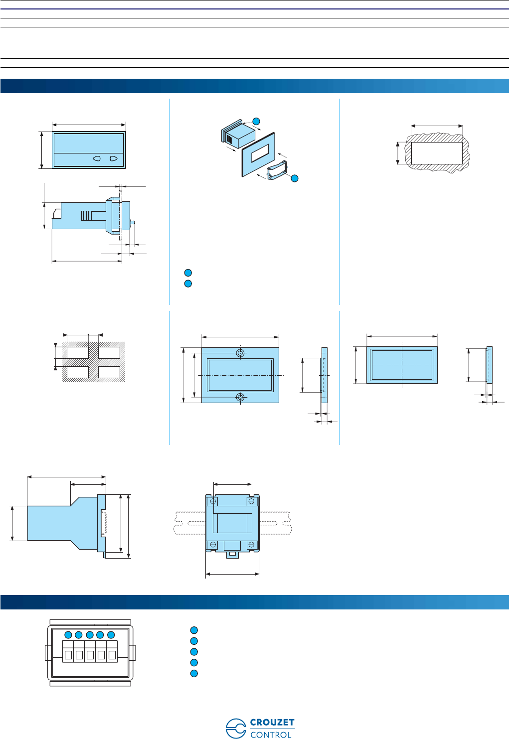
www.crouzet-control.com 45
2
Reset to zero - Panel If not locked during programming
Remise à zéro - Externe (borne 5) If not locked during programming
Scale factor 1 ➞99.9999 (separate for A and B)
Scaling factor 1 ➞99.9999 (separate for A and B)
Decimal point 0
0.0
0.00
0.000
Maximum counting frequency 50 k Hz
CTR24L - 2514 Fixing strip with clip-on yoke Panel cut-out
Seal
Fixing yoke
4 appliances 26546843 - Adaptor for 50 x 25 mm cut-out -
Fixed with screws
26546844 - Adaptor for 50 x 25 mm cut-out -
Fixed with clips
Accessory supplied with the counter
26546840 - DIN rail adaptor
Supply: 10 ➞30 Vc
Supply: GND (0 Vc)
INPA
NC
SET/RESET
Dimensions (mm)
24
22x45
48
6,5
4
19,3
59
CT R2 4L
2
1
22,2
- 0
+0,3
45
+0,6
1
2
+ 0,3
+ 0,6
3045
20 22,2
56
25X50
40
32
4
1
53
28
25X50
4
1
50,4 x 25,4
70
101
45
75
83
45
Connections
1 2 3 4 5
1
2
3
4
5
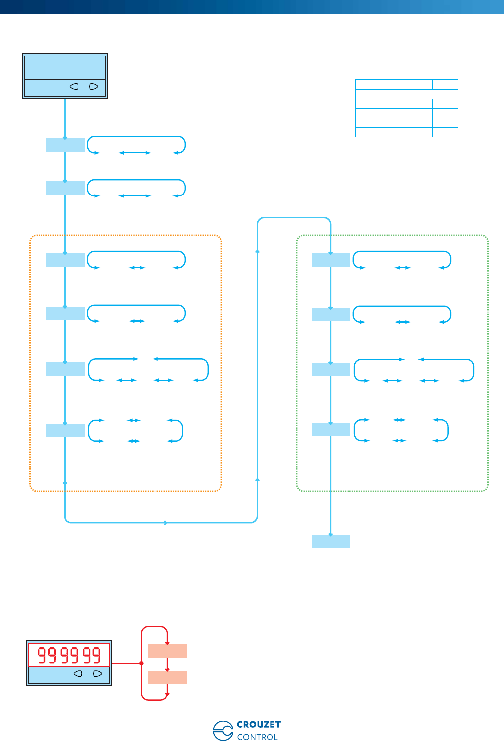
www.crouzet-control.com
46
3
Programming diagram
Applications
2514
Counter 1 Counter 2
InPol PnP nPn
FiltEr
Filter on 30Hz – off Fmax
Multiplying factor
Facto1 01.0000 99.9999
Multiplying factor
FActo2 01.0000 99.9999
Dividing factor
diVto1 01.0000 99.9999
EndPro
oFF on
reSnn1
ManEl:
manual reset red Key and electrical reset
norES:
no reset
ElrES:
only electrical reset
MAnrE:
manual reset
MAnEl norES
ELrES MAnrE reSnn2
ManEl:
manual reset red Key and electrical reset
norES:
no reset
ElrES:
only electrical reset
MAnrE:
manual reset
MAnEl norES
ELrES MAnrE
dPto1
Decimal point
0.0 0.00 0.000
0
Dividing factor
diVto2 01.0000 99.9999
dPto2
Decimal point
0.0 0.00 0.000
0
Count frequency:
DC power supply 24V 12V
Input level Standard
typ. low level 2.5V 2.0V
typ. high level 22.0V 10V
Fmax* kHz kHz
tot.tot 60 20
CT R24L
Counter 1 (partial)
Pressing the right key
displays successively the
following varius values
Counter 2 (total)
total2
SELECTION OF THE DISPLAYED VALUE
total1
CT R24L

www.crouzet-control.com 47
To order:
Customer Service
Crouzet Control
Tel.: +33 (0) 475 802 102
customer.relation@crouzet.com
Crouzet Control,
Technology and expertise,
behind every project
• Local support for all industrial projects.
• A multi-skilled team.
• A sales presence in over 40 countries.
• A Premium offer designed to ensure the excellence of products and services.
• Eco-design integrated in Crouzet's Offer Creation Process.
• Certifications: ISO 9001, ISO 14001, OHSAS 18001.
• Products which comply with international standards (UL, CSA, EC).
• A dynamic R&D department.
In addition to this catalogue, the www.crouzet-control.com
website offers the latest tools, available as free downloads,
including M3 Soft software, technical data sheets for each
product and installation manuals.
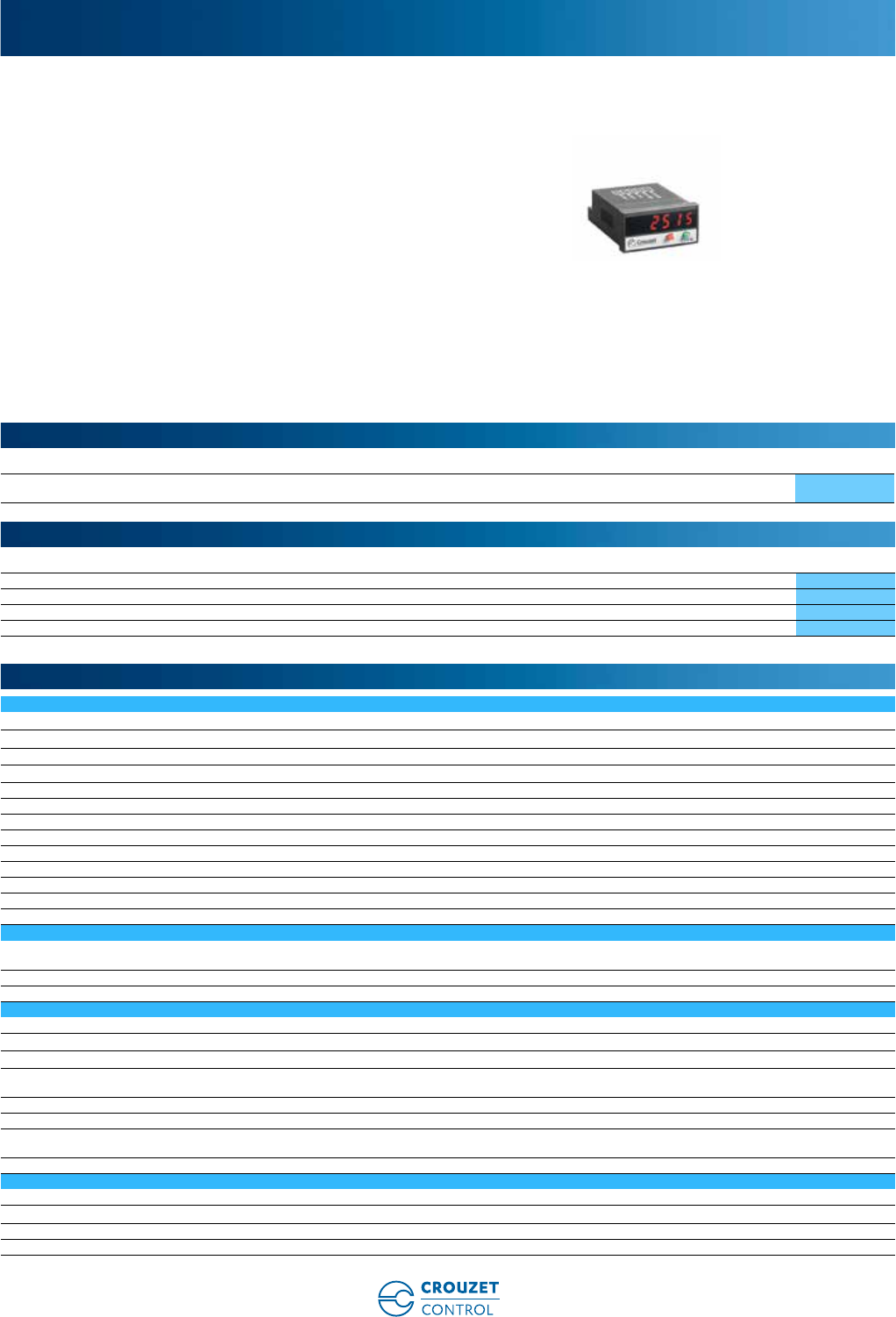
www.crouzet-control.com
48
1
➜ "DUO" multifunction counter - LED 24 x 48 - CTR24L
■ High brightness display: 6-digit LED, height 8 mm
■ Maximum input frequency 50 kHz (in tot.tot function)
■ Programmable dual functions: Counter + Tachometer/
Counter + Counter/Counter + Chronometer/
Chronometer + Chronometer
■ Reset on panel or external with inhibition option
■ Supply: 10 ➞30 Vc
■ Easy to program
■ Scaling factor (Counter - Tachometer)
■ Decimal point (Counter - Tachometer - Chronometer)
■ Timing range 0.001 s ➞999.999 hrs (Chronometer)
■ Impulses or time measured in hrs/min/sec and in real
time (Chronometer)
■ Accessories for 50 x 25 mm cut-out
Type Functions Code
CTR24L - 2515 DUO counter: Counter + Tachometer/Counter + Counter/Counter + Chronometer/Chronometer
+ Chronometer
87623574
Description Code
Adaptor for 50 x 25 mm cut-out - Fixed with screws 26546843
Adaptor for 50 x 25 mm cut-out - Fixed with clips 26546844
DIN rail adaptor 26546840
Clip-fixing kit (supplied with the product) 26546848
Environmental characteristics
Consumption 10 ➞30 Vc max 55 mA with protection against polarity reversal
Connection by 5 screw terminals at rear of casing ✓
Connection capacity 1.5 mm2
Fixed using bracket ✓
Degree of protection front face IP 65
Data memory EEPROM
Temperature limits use (°C) -20 ➞+55
Temperature limits stored (°C) -25 ➞+70
Breakdown voltage According to EN 61010-1: 2000 V / 50 Hz / 1 min
Conformity to standards EN 61000-6-2 - EN 55011 class B
Altitude 2000 m
Certifications UL - cULus - CE
Weight (g) 50
Operating characteristics
Functions Counter + Tachometer/Counter + Counter/Counter + Chronometer/
Chronometer + Chronometer
Display 6-digit LED
Height digits (mm) 8
Input characteristics
Inputs 2 counter inputs, 1 reset input
Low level 0 ➞0.2 x Ub Vc
High level 0.6 x Ub ➞30 Vc
Cyclical ratio Any (maximum frequency given for a cyclical ratio = 1/1)
Schmitt trigger input
Polarity NPN or PNP for all inputs (programming)
Minimum impulse duration for reset 5 ms
Frequency of filtered input Filter active: 30 Hz
Filter disabled: maximum frequency (programming)
Input impedance (kΩ) Appr. 5
Impulse counter
Display details 0 ➞999 999
Elimination of non-significant zeros ✓
Counting input modes INPA input counting
Input INPA Dynamic (uses the same INPA input as the counter)
Electronic multifunction counters without preselection
Part numbers
Accessories
General characteristics
www.crouzet-control.com 49
2
Reset input (terminal 5) Dynamic Reset input connected in parallel with the red SET/RESET button
Sets the counter to the defined preset value
Reset to zero - Panel If not locked during programming
Reset to zero - External (terminal 5) If not locked during programming
Scale factor 1 ➞99.9999
Scaling factor 1 ➞99.9999
Decimal point 0
0.0
0.00
0.000
Maximum counting frequency 50 kHz
Tachometer
Display details 0 ➞999 999
Elimination of non-significant zeros ✓
Conversion time 1/s or 1/min
Input INPA Dynamic (uses the same INPA input as the counter)
Accuracy < 38 Hz: measurement of period duration
> 38 Hz: measurement of duration time base = 26.3 ms
Measurement principle < 0.1%
Scale factor 1 ➞99.9999
Scaling factor 1 ➞99.9999
Decimal point 0
0.0
0.00
0.000
Maximum counting frequency 35 kHz
Chronometer
Display details 0.001 s ➞999 999 h
Elimination of non-significant zeros ✓
Functions In tot.tr function:
GatE.Lo ➞Time measurement if INPB is not active
GatE.hi ➞Time measurement if INPB is active
Inb.Inb ➞Time measurement on/off via the INPB edge
In tr.tr function:
IGatE.Lo ➞Time measurement if INPB is not active
GatE.hi ➞Time measurement if INPB is active
Inb.Inb ➞Time measurement on/off via the INPB edge
InA.Inb ➞Measurement on via the INPA edge, measurement off via the
INPB edge
Input INPA Start/Stop or Gate (depends on the input mode chosen)
Input INPB Start/Stop or Gate (depends on the input mode chosen)
Reset input (terminal 5) Dynamic Reset input connected in parallel with the red SET/RESET button
Sets the counter to the defined preset value
Rest to zero - External (terminal 5) If not locked during programming
Reset to zero - Panel If not locked during programming
Accuracy < 50
Decimal point 0
0.0
0.00
0.000
Time ranges 0.001 s ➞999 999 s
0.001 min ➞99 999 min
0.001 h ➞999 999 h
00 h 00 min 01 s ➞99 h 59 min 59 s
Maximum counting frequency 40 kHz

www.crouzet-control.com
50
3
CTR24L - 2515 Fixing strip with clip-on yoke Panel cut-out
Seal
Fixing yoke
4 appliances 26546843 - Adaptor for 50 x 25 mm cut-out -
Fixed with screws
26546844 - Adaptor for 50 x 25 mm cut-out -
Fixed with clips
Accessory supplied with the counter
26546840 - DIN rail adaptor
Supply: 10 ➞30 Vc
Supply: GND (0 Vc)
INPA
INPB
SET/RESET
Dimensions (mm)
24
22x45
48
6,5
4
19,3
59
CT R2 4L
2
1
22,2
- 0
+0,3
45
+0,6
1
2
+ 0,3
+ 0,6
3045
20 22,2
56
25X50
40
32
4
1
53
28
25X50
4
1
50,4 x 25,4
70
101
45
75
83
45
Connections
1 2 3 4 5
1
2
3
4
5

www.crouzet-control.com 51
4
Programming diagram
Applications
tot.tAc tot.tot
ModE
tr.tr
InPol
PnP nPn
Multiplying factor
Fac.tot
01.0000 99.9999
Dividing factor
diV.tot
01.0000 99.9999
EndPro
INPA count and frequency input
INPA for count1 and count 2
Decimal point and scale factor
are equal for the two counter
INPA input 2 time counter
INPB input 2 time counter
The two times counters work in parallel
and they have the same bases time
INPA input for count
INPB input time count
EndPro
EndPro
FiltEr
Filter on 30Hz – off Fmax
oFF on
InPol
PnP nPn
FiltEr
Filter on 30Hz – off Fmax
oFF on
rES.tot
ManEl: manual reset red Key
and electrical reset
norES: no reset
ElrES: only electrical reset
MAnEl norES
ELrES MAnrE
rESetm1
ManEl: manual reset red Key
and electrical reset
norES: no reset
ElrES: only electrical reset
MAnEl norES
ELrES MAnrE
rESetm2
ManEl: manual reset red Key
and electrical reset
norES: no reset
ElrES: only electrical reset
MAnrE: manual reset
MAnEl norES
ELrES MAnrE
tMode
Time units:
s/h/min
(accurancy depending on position
of the decimal point)
h.m.s
(decimal point setting is ignored)
SEC MIn
hour h.Min.s
tMode
Time units:
s/h/min
(accurancy depending on position
of the decimal point)
h.m.s
(decimal point setting is ignored)
SEC MIn
hour h.Min.s
StArt
GatE.Lo: Counting while INPB is inactive
GatE.hi: Counting while INPB is active
Inb.Inb: Count Start/Stop whit INPB edge
InA.Inb: Count Start whit INPA edge,
count Stop with INPB edge
GatE.Lo GatE.hI
Inb.Inb InA.Inb
StArt
GatE.Lo: Counting while INPB is inactive
GatE.hi: Counting while INPB is active
Inb.Inb: Count Start/Stop whit INPB edge
GatE.Lo GatE.hI
Inb.Inb
Multiplying factor
FActAc
01.0000 99.9999
Dividing factor
diV.tac
01.0000 99.9999
dP
Decimal point
0.0 0.00 0.000
0
dP.tm
Decimal point
0.0 0.00 0.000
0
SEC-1 MIn-1
diSPn
SEC-1:
Value conversion and display in 1/s
Min-1:
Value conversion and display in 1/m
00.1 99.9
Wait0
Max time to wait 00.1…..99.9s
2515
Pressing the right key
displays successively the
following varius values
tachO
total1
CT R2 4L
Pressing the right key
displays successively the
following varius values
total2
total1
CT R2 4L
Pressing the right key
displays successively the
following varius values
time
total
CT R2 4L
Pressing the right key
displays successively the
following varius values
time
time1
CT R2 4L
dP.tot
Decimal point
0.0 0.00 0.000
0
InPol
PnP nPn
Multiplying factor
Fac.tot
01.0000 99.9999
Dividing factor
diV.tot
01.0000 99.9999
FiltEr
Filter on 30Hz – off Fmax
oFF on
rES.nn1
ManEl: manual reset red Key
and electrical reset
norES: no reset
ElrES: only electrical reset
MAnEl norES
ELrES MAnrE
rES.nn2
ManEl: manual reset red Key
and electrical reset
norES: no reset
ElrES: only electrical reset
MAnrE: manual reset
MAnEl norES
ELrES MAnrE
dP.tot
Decimal point
0.0 0.00 0.000
0
tot.tr
EndPro
InPol
PnP nPn
Multiplying factor
Fac.tot
01.0000 99.9999
Dividing factor
diV.tot
01.0000 99.9999
FiltEr
Filter on 30Hz – off Fmax
oFF on
rES.t
ManEl: manual reset red Key
and electrical reset
norES: no reset
ElrES: only electrical reset
MAnrE: manual reset
MAnEl norES
ELrES MAnrE
rES.tot
ManEl: manual reset red Key
and electrical reset
norES: no reset
ElrES: only electrical reset
MAnEl norES
ELrES MAnrE
dP.tot
Decimal point
0.0 0.00 0.000
0
dP.tAt
Decimal point
0.0 0.00 0.000
0
CT R2 4L
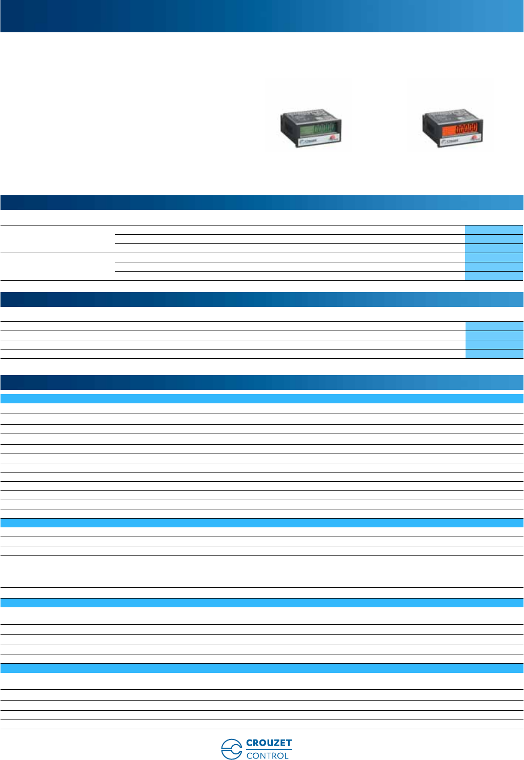
www.crouzet-control.com
52
1
➜ Hour counters without preselection - LCD 24 x 48 - CTR24
■ Display: 8 digits LCD, 8 mm height
■ Built-in module for voltage inputs 10 ➞260 Va
(2224-2324)
■ 4 timing ranges: 99.999.99 hrs - 99.999.59 hrs -
999.999.9 s - 9.999 hrs 59 min 59 s
■ Powered by a lithium battery, service life 8 years
■ Reset on panel or external with inhibition option
■ Backlit model (2323-2333-2324)
■ Accessories for 50 x 25 mm cut-out
Type Type Functions Code
CTR24 non-backlit model 2223 Hour counter, solid state input PNP 87622161
2233 Hour counter, solid state input NPN 87622162
2224 Hour counter, voltage input 87622170
CTR24 model with orange
backlighting
2323 Hour counter, solid state input PNP 87622181
2333 Hour counter, solid state input NPN 87622182
2324 Hour counter, voltage input 87622190
Description Code
Adaptor for 50 x 25 mm cut-out - Fixed with screws 26546843
Adaptor for 50 x 25 mm cut-out - Fixed with clips 26546844
DIN rail adaptor 26546840
Clip-fixing kit (supplied with the product) 26546848
Environmental characteristics
Consumption Backlighting: 24 Vc ± 20% 50 mA
Connection by 8 screw terminals at rear of casing ✓
Connection capacity 1.5 mm2
Fixed using bracket ✓
Degree of protection front face IP 65
Temperature limits use (°C) -10 ➞+60
Temperature limits stored (°C) -20 ➞+70
Breakdown voltage According to EN 610110-1: 2000 V / 50 Hz / 1 min.
Conformity to standards EN 61000-6-2 - EN 55011 class B
Altitude 2000 m
Certifications UL - cULus (pending) - CE
Weight (g) 50
Operating characteristics
Function Hour counter
Display 8-digit LCD
Height digits (mm) 8
Time ranges 0 ➞99 999.99 h
0 ➞99 999.59 h
0 ➞9 999 999.9 s
0 ➞9 999 h 59 min 59 s
Time base: Crystal controlled (Accuracy ± 100) ✓
Input 2223-2323
One start/stop input by volt-free contact or NPN/PNP open-collector
transistor (terminals 2-6)
✓
Low level 0 ➞0.7 Vc
High level 4 ➞30 Vc PNP
Min time closed > 100 ms
Input impedance 100 kΩ PNP
Input 2233-2333
One start/stop input by volt-free contact or NPN/PNP open-collector
transistor (terminals 2-6)
✓
Low level 0 ➞0.7 Vc
High level 3 ➞30 Vc
Minimum time closed > 100 ms
Input impedance 1 MΩ
Electronic counters without preselection
Part numbers
Accessories
General characteristics
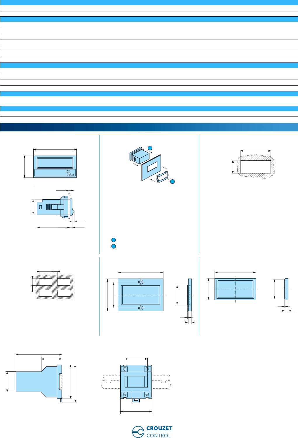
www.crouzet-control.com 53
2
Reset - External 2223-2323 & 2233-2333
Volt-free contact or open collector (terminals 3-6) ✓
Minimum time closed 50 ms
Input 2224-2324
One start/stop input Two voltage levels (terminals 3-6) ✓
Voltage - Terminals 1-2 10 ➞260 Vz
Input impedance 160 KΩ
Minimum pulse time c100 ms
Minimum pulse time a100 ms
Low level 0 ➞2 Vz
High level 10 ➞260 Vz
Reset - External 2224-2324
Voltage - Terminals 2-3 ✓
Minimum pulse time 16 ms
Low level 0 ➞2 Vz
High level 10 ➞260 Vz
Reset to zero - Panel
Reset via Inhibited: Terminals 4-6 not connected
Active: Terminals 4-6 connected
Supply
1 lithium battery - Life (years) 8
CTR24 Fixing strip with clip-on yoke Panel cut-out
Seal
Fixing yoke
4 appliances 26546843 - Adaptor for 50 x 25 mm cut-out -
Fixed with screws
26546844 - Adaptor for 50 x 25 mm cut-out -
Fixed with clips
Accessory supplied with the counter
26546840 - DIN rail adaptor
Dimensions (mm)
24
22x45
48
47,7 3
2,8
19,3
CTR24
2
1
22,2
- 0
+0,3
45
+0,6
1
2
+ 0,3
+ 0,6
3045
20 22,2
56
25X50
40
32
4
1
53
28
25X50
4
1
50,4 x 25,4
70
101
45
75
83
45
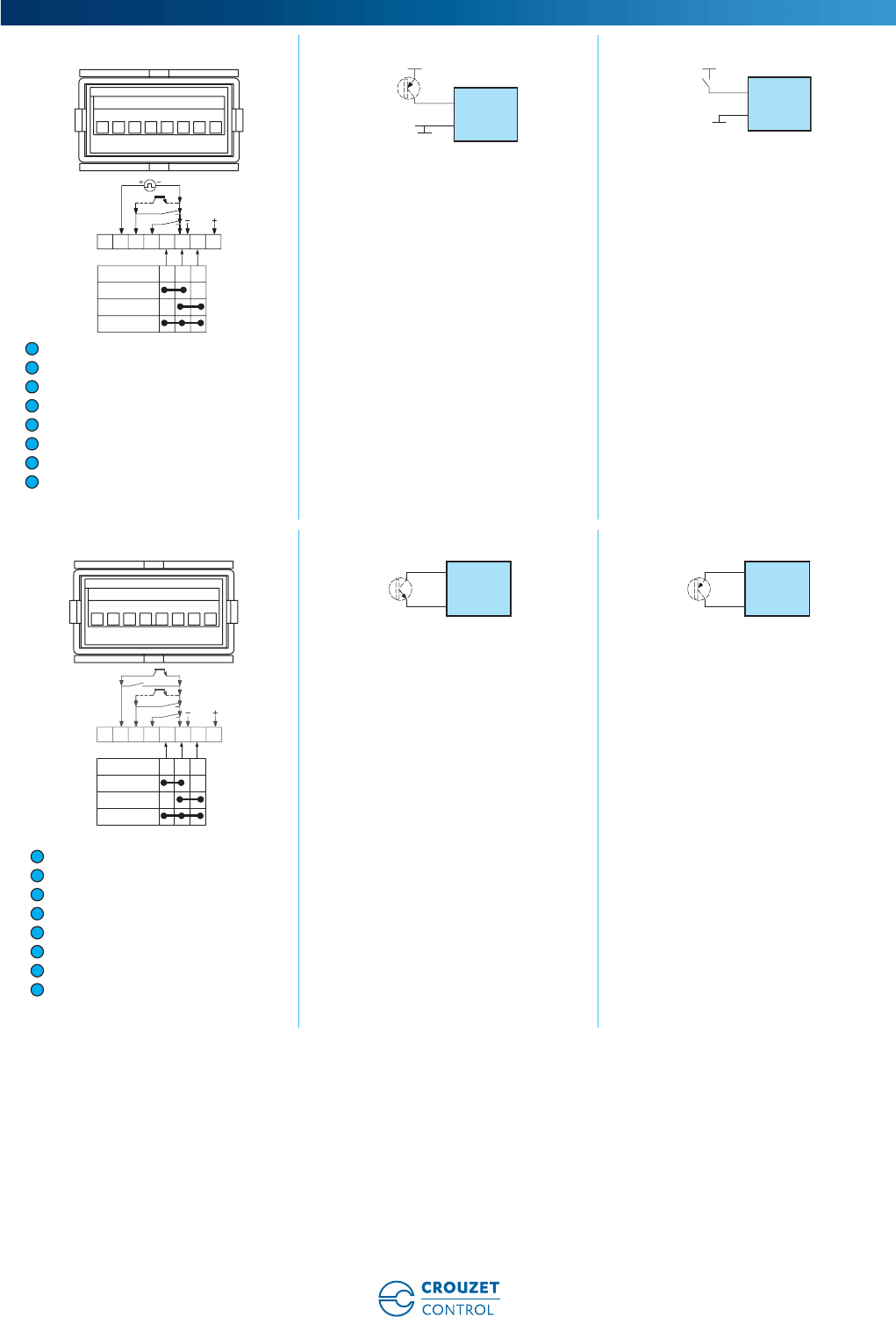
www.crouzet-control.com
54
3
2223-2323 2223-2323 2223-2323
NC
Start/Stop input
Reset input 100 ms
Enable panel reset
Mode 1 (Time selection)
0 V common/ (BL- only 23xx)
Mode 2 (Time selection)
Backlighting option + 24 Vc (only 2323)
Start/Stop input
Transistor PNP
Start/Stop input PNP
2233-2333 2233-2333 2233-2333
NC
Start/Stop input
Reset input 100 ms
Enable panel reset
Mode 1 (Time selection)
0 V common/ (BL- only 23xx)
Mode 2 (Time selection)
Backlighting option + (only 2333)
Start/Stop or reset input NPN - Transistor Start/Stop or reset input PNP - Transistor
Connections
1234567 8
821 3 4 5 6 7
9999h59m 59s
9999999.9s
99999h59m
99999.99h
30 Vdc
2
6
2
6
1
2
3
4
5
6
7
8
1 3456728
821 3 4 5 6 7
9999h59m 59s
9999999.9s
99999h59m
99999.99h
2 - 3
6
3 - 2
6
1
2
3
4
5
6
7
8
www.crouzet-control.com 55
4
2233-2333 2234-2324 2234-2324
Start/Stop or reset input NPN - Transistor Start/Stop input
AC/DC common
Reset input
Enable panel reset
Mode 1 (Time selection)
0 V common/ (BL- only 23xx)
Mode 2 (Time selection)
Backlighting option + 24 Vc (only 2324)
Start/Stop or reset input - Voltage
2234-2324 2234-2324 2234-2324
Start/Stop or reset input - Contact
supplied with power
Start/Stop or reset input PNP
Transistor or 3-wire PNP proximity
sensor for leakage current
detector < 1 mA
Start/Stop or reset input NPN
Transistor or 3-wire NPN proximity
sensor for leakage current
detector < 1 mA
2234-2324 2234-2324
Start/Stop or reset input: 2-wire
proximity sensor R=470 Ω/2 W for 2-
wire leakage current detector ≤ 1 mA
Start/Stop or reset input: 2-wire
proximity sensor R=470 Ω/2 W for 2-
wire leakage current detector ≤ 1 mA
3 - 2
6
10260
2
10260
V ac/dc
31
V ac/dc
45678
821 3 4 5 6 7
9999h59m 59s
9999999.9s
99999h59m
99999.99h
10-240V~/ 2
1 - 3
1
2
3
4
5
6
7
8
2
1 - 3
10-240V~/
1 - 3
2
PNP
+
OV
10-260V
1 - 3
2
NPN
+
OV
10-260V
1 - 3
2
OV
30 V max
OV
1 - 3
2
30 V max

www.crouzet-control.com
56
1
➜ Totalizers without preselection - LCD 24 x 48 - CTR24
■ Display: 8-digit LCD, height 8 mm
■ Powered by a lithium battery
■ Counter inputs: solid state (4-30 Vc) or voltage
(10 ➞260 Va)
■ Reset on panel or external with inhibition option
■ Backlit model (2341-2351-2342)
■ Counting directions can be selected with input (2241-
2341/2251-2351)
■ Accessories for 50 x 25 mm cut-out
Type Type Functions Code
CTR24 non-backlit model 2241 Solid state input, lithium battery PNP/NPN 87622061
2251 Solid state input, lithium battery NPN/NPN 87622062
2242 Voltage input, lithium battery 87622070
CTR24 model with orange
backlighting
2341 Solid state input, lithium battery PNP/NPN 87622081
2351 Solid state input, lithium battery NPN/NPN 87622082
2342 Voltage input, lithium battery 87622090
Description Code
Adaptor for 50 x 25 mm cut-out - Fixed with screws 26546843
Adaptor for 50 x 25 mm cut-out - Fixed with clips 26546844
DIN rail adaptor 26546840
Clip-fixing kit (supplied with the product) 26546848
Environmental characteristics
Consumption Backlighting: 24 Vc ± 20% 50 mA
Connection by 8 screw terminals at rear of casing ✓
Connection capacity 1.5 mm2
Fixed using bracket ✓
Degree of protection front face IP 65
Temperature limits use (°C) -10 ➞+60
Temperature limits stored (°C) -20 ➞+70
Breakdown voltage According to EN 61010-1: 2000 V / 50 Hz / 1 min
Conformity to standards EN 61000-6-2 - EN 55011 class B
Altitude 2000 m
Certifications UL - cULus (pending) - CE
Weight (g) 50
Operating characteristics
Function Impulse counter
Display 8-digit LCD
Height digits (mm) 8
Counting capacity -9.999.999 ➞99.999.999 with elimination of zeros
Inputs 2241-2341
1 slow counting input for contact closure on NPN open-collector transistor
input (terminals 2-6)
✓
1 input for high speed counting signal from voltage level (terminals 1-6) 4 ➞30 Vc
Low level 0 ➞0.7 Vc
High level 4 ➞30 Vc PNP
High-speed counting 12 KHz max.
42 µs PNP
Input impedance 100 KΩ PNP
Inputs 2251-2351
1 slow counting input for contact closure on NPN open-collector transistor
input (terminals 2-6)
✓
1 input for high speed counting signal from voltage level (terminals 1-6) 3 ➞30 Vc
Low level 0 ➞0.7 Vc
High level 3 ➞30 Vc
High-speed counting 7 KHz max.
70 µs NPN
Input impedance 1 MΩ
Electronic counters without preselection
Part numbers
Accessories
General characteristics
www.crouzet-control.com 57
2
Reset - External 2241-2341 & 2251-2351
Volt-free contact or open collector (terminals 3-6) ✓
Inputs 2242-2342
1 input for slow counting 2 voltage levels ✓
Voltage - Terminals 1-2 10 ➞260 Vz
Input impedance (kΩ) 160
Slow counting 30 Hz
Minimum pulse time 16 ms
Low level 0 ➞2 Vz
High level 10 ➞260 Vz
Reset - External 2242-2342
Voltage - Terminals 2-3 ✓
Minimum pulse time 16 ms
Low level 0 ➞2 Vz
High level 10 ➞260 Vz
Reset to zero - Panel
Reset via Inhibited: Terminals 4-6 not connected
Active: Terminals 4-6 connected
Supply
1 lithium battery - Life (years) 8
CTR24 Fixing strip with clip-on yoke Panel cut-out
Seal
Fixing yoke
4 appliances 26546843 - Adaptor for 50 x 25 mm cut-out -
Fixed with screws
26546844 - Adaptor for 50 x 25 mm cut-out -
Fixed with clips
Accessory supplied with the counter
26546840 - DIN rail adaptor
Dimensions (mm)
24
22x45
48
47,7 3
2,8
19,3
CTR24
2
1
22,2
- 0
+0,3
45
+0,6
1
2
+ 0,3
+ 0,6
3045
20 22,2
56
25X50
40
32
4
1
53
28
25X50
4
1
50,4 x 25,4
70
101
45
75
83
45
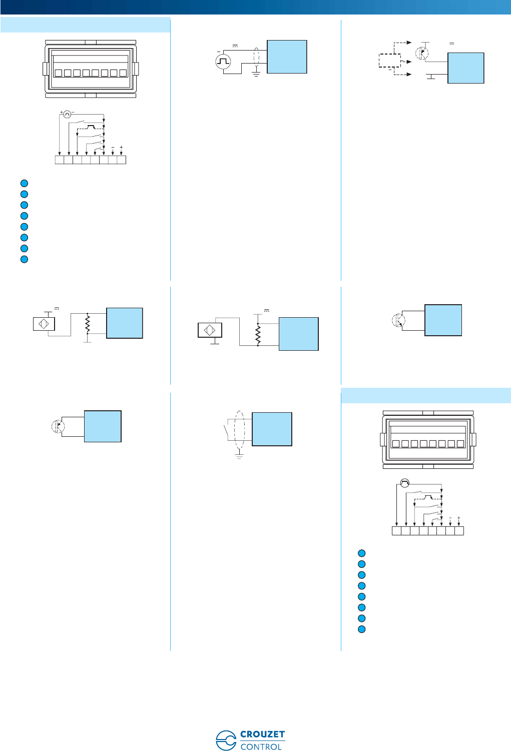
www.crouzet-control.com
58
3
2241-2341 2241-2341 2241-2341
Fast count
Slow count
Reset input 12 ms
Enable panel reset
Mode count direction
0 V common/ (BL- only 23xx)
Backlighting option (only 2341)
Backlighting option + 24 Vc (only 2341)
PNP fast count input - Voltage PNP fast count input Transistor or 3-wire
PNP proximity sensor (for leakage
current detector ≤ 1 mA)
2241-2341 2241-2341 2241-2341
2-wire proximity sensor fast count input 2-wire proximity sensor fast count input Slow count input (2) or reset input (3)
2241-2341 2241-2341 2251-2351
Slow count input (2) or reset input (3) Slow count input (2) or reset input (3) -
Contact not supplied with power
Fast count
Slow count
Reset input 12 ms
Enable panel reset
Mode count direction
0 V common/ (BL- only 23xx)
Backlighting option + (only 2351)
Backlighting option + 24 Vc (only 2351)
Connections
821 3 4 5 6 7
768
30 V d c - 12 KH z
12345
+
3
5
4-30V
1
6
1
6
PNP
+
OV
4-30V
1
2
3
4
5
6
7
8
1
6
OV
4-30V
OV
1
6
4-30V
2 - 3
6
3 - 2
6
3 - 2
6
821 3 4 5 6 7
12345678
7KH z
30H z
1
2
3
4
5
6
7
8
www.crouzet-control.com 59
4
2251-2351 2251-2351 2251-2351
Fast count input NPN - Voltage Fast count input NPN Transistor or 3-wire
PNP proximity sensor (for leakage current
detector ≤ 1 mA) 2-wire proximity sensor fast count input
2251-2351 2251-2351 2251-2351
Slow count input (2) or reset input (3) Slow count input (2) or reset input (3) Slow count input (2) or reset input (3)
Contact not supplied with power
2242-2342 2242-2342 2242-2342
Fast count
AC/DC common
Reset input 12 ms
Enable panel reset
count direction
0 V common/ (BL- only 23xx)
Backlighting option - (only 2342)
Backlighting option + 24 Vc (only 2342)
Counter or reset input - Voltage Counter or reset input -
Contact supplied with power
2242-2342 2242-2342 2242-2342
Counter or reset input PNP Transistor or
3-wire PNP proximity sensor (for leakage
current detector < 1 mA)
Counter or reset input NPN Transistor or
3-wire PNP proximity sensor (for leakage
current detector < 1 mA)
Start/Stop or reset input: 2-wire proximity
sensor R=470 Ω/2 W for 2-wire leakage
current detector ≤ 1 mA
1
6
1
6
NPN
+
OV
4-30V
OV
1 - 3
2
2 - 3
6
3 - 2
6
3 - 2
6
821 3 4 5 6 7
8
10
260
30Hz
10
260
2
Vac/dc Vac/dc
1 34 657
10-240V~/ 2
1 - 3
2
1 - 3
10-240V~/
1
2
3
4
5
6
7
8
1 - 3
2
PNP
+
OV
10-260V
1 - 3
2
NPN
+
OV
10-260V
1 - 3
2
OV
30 V max
www.crouzet-control.com
60
1
➜ Hour counters 48 X 48 - CHM48
■ AC: capacity 100.000 hrs (99.999.99 hrs)
■ DC: capacity 1.000.000 hrs (999.999.99 hrs)
■ Operation indicator
■ Panel mounted
■ DIN rail mounted with connector base (accessory part
number: 26546845)
■ IP52
■ Highly resistant to shocks and impacts
■ Excellent visibility due to the large digit size
Type Operating frequency (Hz) Voltages Code
CHM48 50 20 ➞30 Va99772710
50 42 ➞48 Va99772711
50 100 ➞130 Va99772712
50 360 ➞440 Va99772713
50 187 ➞264 Va99772714
60 100 ➞130 Va99772715
60 187 ➞264 Va99772716
60 360 ➞440 Va99772717
60 20 ➞30 Va99772718
60 42 ➞48 Va99772719
c10 ➞30 Vc99772810
c36 ➞80 Vc99772811
c100 ➞130 Vc99772812
Description Code
Adaptor for 72 x 72 mm cut-out 26546842
Adaptor for 55 x 55 mm cut-out 26546846
DIN rail adaptor 26546845
General characteristics
Counting capacity Va: 99 999.99
Vc: 999.999.99
Reset to zero Not included
Read accuracy 1/100 h
Height digits (mm) 4
Colour of hour numbers White on a black background
Colour of decimal digits Red on a black background
Accuracy Va: frequency + 30 ms
Vc: < 0.003% (24 hrs)
Counting input mode Addition
Operation indicator Va: rotating red lines
Vc: 1/100 hr 1 digit in 36 s
Degree of protection front face IP52
Mounting Any
Temperature limits use (°C) -15 ➞+50
Temperature limits stored (°C) -40 ➞+80
Certifications UL (pending)
Connections (panel mounted version) Screw terminals - 6.35 mm Faston connectors
Connections (DIN rail mounted version) Screw terminals with accessory 26 546 845
Connection capacity 2.5 mm2
Consumption Vc: 10 ➞30 approx. 500 mW/100 ➞130 approx. 750 mW/
Va 50 Hz: 20 ➞30 approx. 0.3 VA/42 ➞48 approx. 0.25 VA/100 ➞130
approx. 0.6 VA/187 ➞264 approx. 1.2 VA/360 ➞440 approx. 1.65 VA
Vibration resistance 50 m/s2 (10-500 Hz) IEC 68-2-6
Test voltage for AC models 2 000 Va 50 Hz
Weight (g) 50
Electromechanical hour counters
Part numbers
Accessories
General characteristics
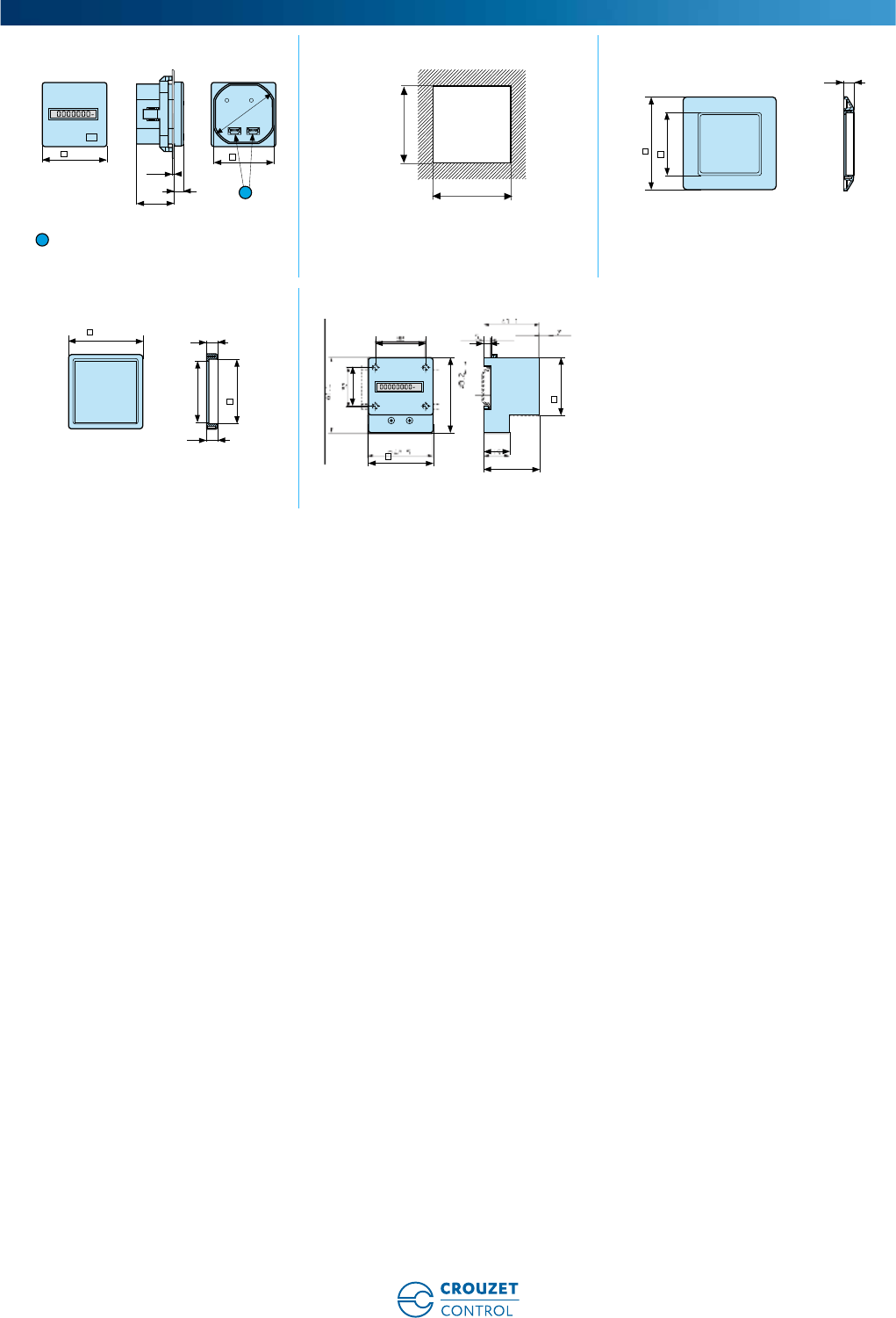
www.crouzet-control.com 61
2
Panel mounted Panel cut-out 26546842 - Adaptor for 72 x 72 mm cut-out
Screw terminals
26546846 - Adaptor for 55 x 55 mm cut-out 26546845 - DIN rail mounted
Dimensions (mm)
48
h
45
max.9
7
28
Ø 50
1
45
+0.6
0
45 +0.6
0
7,4
72
45,4
1
55
48,1
0
-0,2
0
+0,2
6
±0,1
7,4
±0,1
45,4
48
61,5
41,1
19
48,5
5
38
32
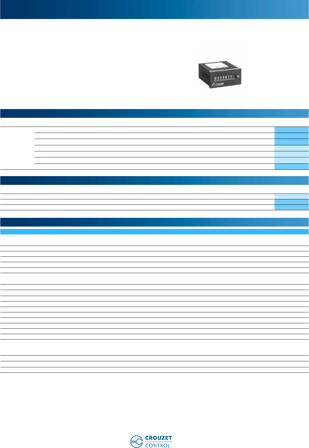
www.crouzet-control.com
62
1
➜ Hour counters 24 X 48 - CHM24
■ Va: capacity 100.000 hrs (99.999.99 hrs)
■ Vc: capacity 1.000.000 hrs (999.999.99 hrs)
■ Operation indicator
■ Panel mounted
■ IP65 (with accessory 26546847)
■ Highly resistant to shocks and impacts
■ Compact size
■ Excellent visibility due to the large digit size
Type Operating frequency (Hz) Voltages Code
CHM24 50 20 ➞30 Va99782710
50 100 ➞130 Va99782712
50 187 ➞264 Va99782714
60 100 ➞130 Va99782715
60 187 ➞264 Va99782716
60 20 ➞30 Va99782718
c10 ➞30 Vc99782810
Description Code
Set of seals 26546847
Adaptor for 50 x 25 mm cut-out - Fixed with screws 26546843
Adaptor for 50 x 25 mm cut-out - Fixed with clips 26546844
General characteristics
Counting capacity Va: 99.999.99
Vc: 999.999.99
Reset to zero Not included
Read accuracy 1/100 h
Height digits (mm) 4
Colour of hour numbers White on a black background
Colour of decimal digits Red on a black background
Accuracy Va: frequency + 30 ms
Vc: < 0.003% (24 hrs)
Counting input mode Addition
Operation indicator Va: rotating red lines/DC: 1/100 hr 1 digit in 36 s
Protection rating IP52 or IP65 with accessory (26546847)
Mounting position Any
Temperature limits use (°C) -10 ➞+50
Temperature limits stored (°C) -40 ➞+80
Certifications CE - UL (pending)
Connections (panel mounted version) Screw terminals - 6.35 mm Faston connectors
Tightening torque (Nm) 0.8
Connection capacity 2.5 mm2
Consumption Vc: 10 ➞30 approx. 500 mW/100 ➞130 approx. 750 mW/
Va 50 Hz: 20 ➞30 approx. 0.3 VA/100 ➞130 approx. 0.6 VA/187 ➞264
approx. 1.2 VA
Vibration resistance 50 m/s2 (10-500Hz) IEC 68-2-6
Test voltage for AC models 2 000 Va 50 Hz
Weight (g) 50
Electromechanical hour counters
Part numbers
Accessories
General characteristics
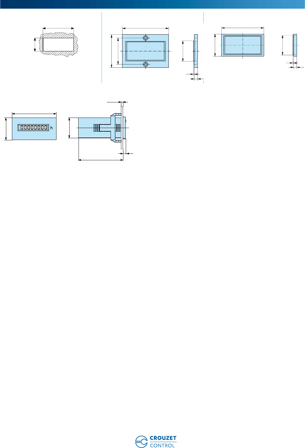
www.crouzet-control.com 63
2
Panel cut-out 26546843 - Adaptor for cut-out 26546844 - Adaptor for cut-out
CHM24
Dimensions (mm)
22,2
- 0
+0,3
45
+0,6
56
25X50
40
32
4
1
53
28
25X50
4
1
max.19
24
22 x 45
48,5
48
3
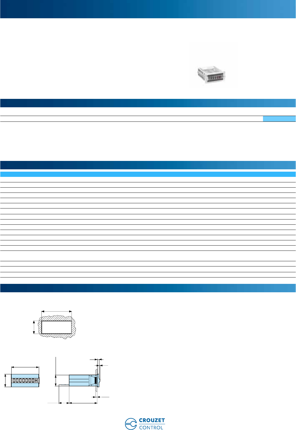
www.crouzet-control.com
64
1
➜ Hour counters 15 X 32 - CHM15
■ Capacity 100.000 hrs (99.999.99 hrs)
■ Wide range of voltages: 4.5 ➞35 Vc
■ Panel mounted
■ IP65
■ Highly resistant to shocks and impacts
■ Compact size
■ Excellent visibility thanks to the large digit size
Type Operating frequency (Hz) Voltages Code
CHM15 c4.5 ➞35 Vc99792810
General characteristics
Counting capacity 99.999.99
Reset to zero Not included
Read accuracy 1/100 h
Height digits (mm) 4
Colour of hour numbers White on a black background
Colour of decimal digits Red on a black background
Accuracy Vc: < 0.003% (24 hrs, 25°C)
Counting input mode Addition
Degree of protection front face IP65
Mounting position Horizontal readout of digits
Temperature limits use (°C) -10 ➞+60
Temperature limits stored (°C) -40 ➞+80
Certifications CE - UL (pending)
Connections (panel mounted version) Flying leads: 150 mm
Consumption 5 Vc approx. 82 mW/12 Vc approx. 135 mW/24 Vc approx. 135 mW/
max 170 mW
Vibration resistance 50 m/s2 (10-500 Hz) IEC 68-2-6
Test voltage for AC models 2 000 Va 50 Hz
Weight (g) 20
Panel cut-out
CHM15
Electromechanical hour counters
Part numbers
General characteristics
Dimensions (mm)
13
- 0
+0,5
30
+0,3
32
15
max.3
150 32,7
1,1
2
13 x 29.9
www.crouzet-control.com 65
1
➜ DIN rail mounting hour counters - CHMDR
■ Width equivalent to 2 modules
■ Capacity 100.000 hrs (99.999.99 hrs)
■ Extended temperature range: -10 ➞+70°C (a version)
■ DIN rail mounted according to EN 50022
■ IP65 on panel
■ Highly resistant to shocks and impacts
■ Colour: RAL 7035 grey
■ Screw terminals
Type Operating frequency (Hz) Voltages Code
CHMDR 50 24 Va99793710
50 115 Va99793712
50 230 Va99793714
c10 ➞27 Vc99793810
General characteristics
Counting capacity 99.999.99
Reset to zero Not included
Read accuracy 1/100 h
Height digits (mm) 3.5
Colour of hour numbers White on a black background
Colour of decimal digits Black on a white background
Accuracy Va/Vc: < 0.01% (24 hrs)
Counting input mode Addition
Degree of protection front face IP 65
Tolerance Va ± 10%
Temperature limits use (°C) Va: -10 ➞+70
Vc: -10 ➞+50
Temperature limits stored (°C) -40 ➞+80
Certifications CE
Connection Screw terminals
Consumption Va: approx. 2.5 VA
Vc: approx. 1 W
Vibration resistance 1G (10-500 Hz)
Test voltage for AC models 2 000 Va 50 Hz
Weight (g) 60
CHMDR
Electromechanical hour counters
Part numbers
Accessories
General characteristics
Dimensions (mm)
h
6
60
44
45
90
36
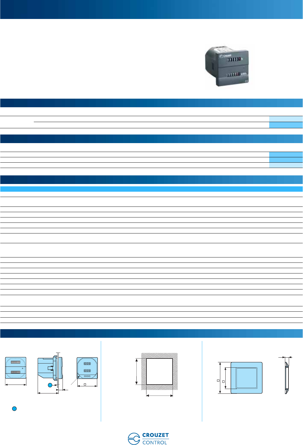
www.crouzet-control.com
66
1
➜ Dual-function counter (hour counter and watt-hour meter) 48 x 48 - CEM48
■ Dual-function counter (hour counter and watt-hour meter)
■ Capacity 100.000 hrs (99.999.99 hrs)
■ Remote readout via SO output
■ Panel mounted
■ IP 65
■ Excellent visibility due to the large digit size
Type Designation Operating frequency (Hz) Voltages Code
CEM48 Single-phase (max. 16 A) 50 / 60 115 Va99780712
Single-phase (max. 16 A) 50 / 60 230 Va99780714
Description Code
Adaptor for 72 x 72 mm cut-out 26546842
Adaptor for 55 x 55 mm cut-out 26546846
DIN rail adaptor 26546841
General characteristics
Counting capacity 99.999.9 hrs/99.999.9 kWh
Display by LED LED backlight: the counter is powered up
LED flashing: the energy is being measured
Reset to zero Not included
Read accuracy 1/10 h
Height digits (mm) 4
Colour of hour numbers White on a black background
Colour of decimal digits Red on a black background
Accuracy Hour counter: ± 2%
Watt-hour meter: Class B (1%)
Current Imax: 16 A
Current limits between 20 mA and 16 A
Use for current > 20 mA
Degree of protection front face IP65
Mounting Any
Temperature limits use (°C) - 20 ➞+55
Temperature limits stored (°C) - 25 ➞+65
Certifications CE
Connection Screw terminals
Connection capacity 2.5 mm2
Output signal Watt-hour meter: 10 impulses/hr, 5 ➞30 Vc, Imax: 20 mA
Hour counter: 1000 impulses/kWh, 5 ➞30 Vc, Imax: 20 mA
Standards EN 50470-1, EN 50470-3
Test voltage for AC models 2 000 Va 50 Hz
Weight (g) 83
Panel mounted Panel cut-out 26546842 - Adaptor for 72 x 72 mm cut-out
9 max.
Dual-function electromechanical counters
Part numbers
Accessories
General characteristics
Dimensions (mm)
48
Ø 50
L out
L inN
SO kWh
GND
45
48
9
1
45
+0.6
0
45
+0.6
0
7,4
72
45,4
1
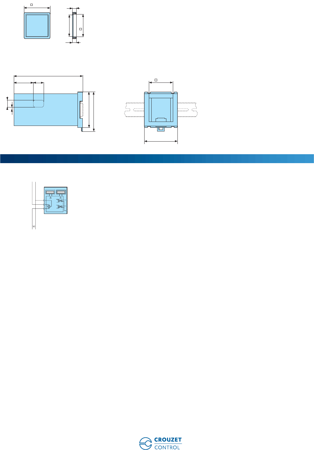
www.crouzet-control.com 67
2
26546846 - Adaptor for 55 x 55 mm cut-out
26546841 - DIN rail adaptor
CEM48
55
48,1
0
-0,2
0
+0,2
6
±0,1
7,4
±0,1
45,4
50 +0,5
0
41 22
145
15
75
83
5,5
70
Connections
006695006695
kWh h
N
NL
Lout
Lin SO h
SO kWh
GND
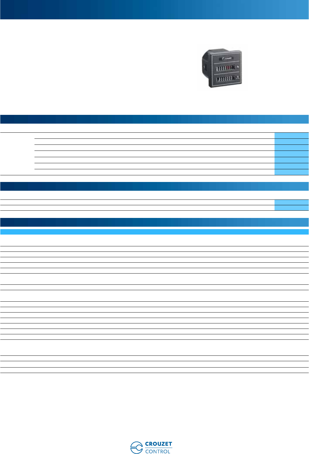
www.crouzet-control.com
68
1
➜ Dual-function counters (hour counter and impulse counter) 48 x 48 - CMM48
■ Dual-function counter (hour counter and impulse
counter)
■ Va: capacity 100.000 hrs (99.999.99 hrs)
■ Vc: capacity 1.000.000 hrs (999.999.99 hrs)
■ Operation indicator
■ Panel mounted
■ IP52
■ Highly resistant to shocks and impacts
■ Excellent visibility thanks to the large digit size
Type Operating frequency (Hz) Voltages Code
CMM48 50 20 ➞30 Va99779710
50 100 ➞130 Va99779712
50 187 ➞264 Va99779714
60 20 ➞30 Va99779718
60 100 ➞130 Va99779715
60 187 ➞264 Va99779716
Vc10 ➞30 Vc99779810
Description Code
Adaptor for 72 x 72 mm cut-out 26546842
Adaptor for 55 x 55 mm cut-out 26546846
General characteristics
Counting capacity Va: 99.999.99 hrs
Vc: 999.999.99 hrs
Reset to zero Not included
Read accuracy 1/100 h
Height digits (mm) 4
Colour of hour numbers White on a black background
Colour of decimal digits Red on a black background
Accuracy Va: frequency + 30 ms
Vc: < 0.003% (24 hrs)
Counting input mode Addition
Operation indicator Va: rotating red lines
Vc: 1/100 hr 1 digit in 36 s
Degree of protection front face IP52
Mounting position Any
Temperature limits use (°C) -15 ➞+50
Temperature limits stored (°C) -40 ➞+80
Certifications CE - UL (pending)
Connections (panel mounted version) Screw terminals - 6.35 mm Faston connectors
Connection capacity 2.5 mm2
Consumption Vc: 10 ➞30 approx. 1 W
Va 50 Hz: 20 ➞30 approx. 0.53 VA
100 ➞130 approx. 1.43 VA/187 ➞264 approx. 3 VA
Vibration resistance 50 m/s2 (10-500 Hz) IEC 68-2-6
Test voltage for AC models 2 000 Va 50 Hz
Weight (g) 65
Dual-function electromechanical counters
Part numbers
Accessories
General characteristics
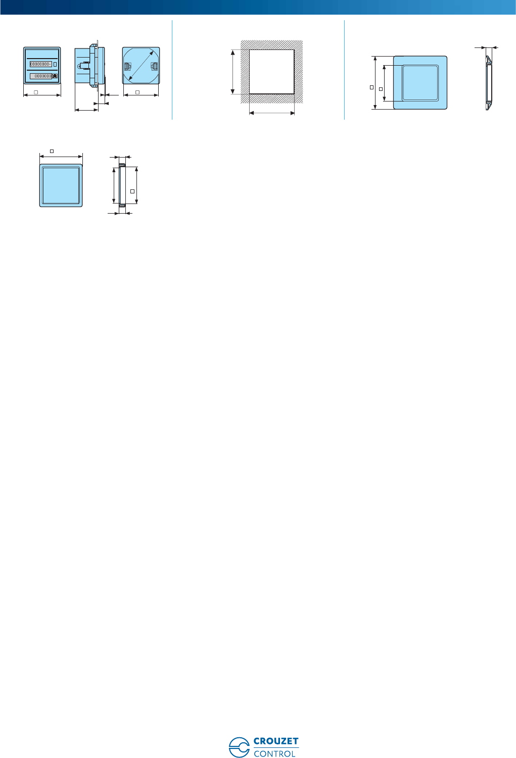
www.crouzet-control.com 69
2
Panel mounted Panel cut-out 26546842 - Adaptor for 72 x 72 mm cut-out
26546846 - Adaptor for 55 x 55 mm cut-out
Dimensions (mm)
48 45
Ø 50
h
8
1,2
30
45
+0.6
0
45
+0.6
0
7,4
72
45,4
55
48,1
0
-0,2
0
+0,2
6
±0,1
7,4
±0,1
45,4
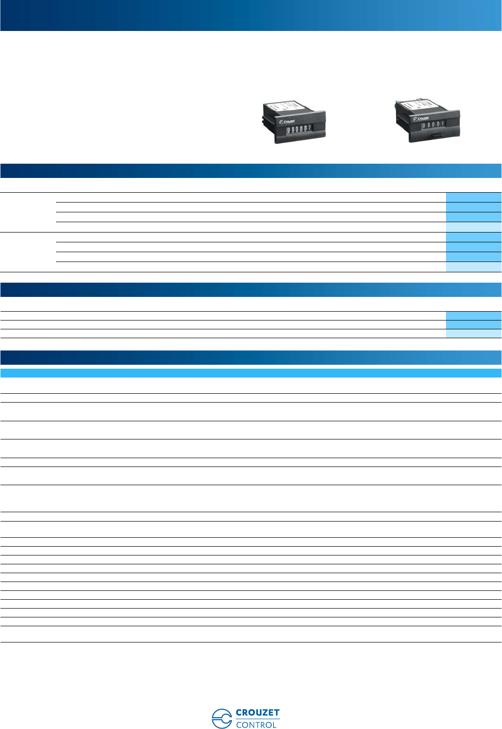
www.crouzet-control.com
70
1
➜ Impulse counters 24 x 48 - CIM24
■ 5 or 6 digits, height of digits 4 mm
■ With or without manual reset
■ White digits on a black background
Type Number of digits Operating frequency (Hz) Voltages Code
Without
manual reset
6 50 / 60 230 Va99777714
6 50 / 60 24 Va99777710
6Vc24 Vc99777810
6Vc12 Vc99777815
With manual
reset
5 50 / 60 230 Va99777724
5 50 / 60 24 Va99777720
5Vc24 Vc99777820
5Vc12 Vc99777825
Description Code
Adaptor for 50 x 25 mm cut-out - Fixed with screws 26546843
Adaptor for 50 x 25 mm cut-out - Fixed with clips (supplied with the product) 26546844
Adaptor for 48 x 48 mm cut-out 26546849
General characteristics
Counting capacity 999.999 impulses without manual reset
99.999 impulses with manual reset
Height digits (mm) 4
Max. count rate Va ➞10 impulses/s
Vc ➞10 impulses/s
Min. count rate Va ➞50 ms
Vc ➞50 ms
Min pause time between 2 pulses Va ➞50 ms
Vc ➞50 ms
Max. pulse length (count coil) Unlimited
Voltage variation 12/24 Vc: ± 10%
Va: ± 10%
Consumption 24 Va: 0.75 VA
230 Va: 1.5 VA
12/24 Vc: 0.5 W
Mechanical life count function (operations) > 50 x 106
Test voltage according to standard IEC 255-5 U < 60 V: 500 V
U > 60 V: 2 000 V
Protection Housing IP40
Degree of terminal protection IP00
Environmental protection Plated or stainless steel components
Maintenance None
Operating position Any
Temperature limits use (°C) - 10 ➞+50
Temperature limits stored (°C) - 40 ➞+80
Certifications CE
Connection 6.35 Faston connectors or screw terminals
Mounting With clip
Weight (g) 65
Electromechanical impulse counters
Part numbers
Accessories
General characteristics
www.crouzet-control.com 71
2
Panel cut-out 26546844 - Adaptor for 50 x 25 mm cut-out 26546843 - Adaptor for 50 x 25 mm cut-out
26546849 - Adaptor for 50 x 25 mm cut-out
9977771/81 - 6 digits 9977772/82 - 5 digits
Dimensions (mm)
22,2
- 0
+0,3
45
+0,6
53
28
25X50
4
1
56
25X50
40
32
4
1
48
11
45,2
8
22,2
24
48 1
49
4
24
48
24
53,8
4
16
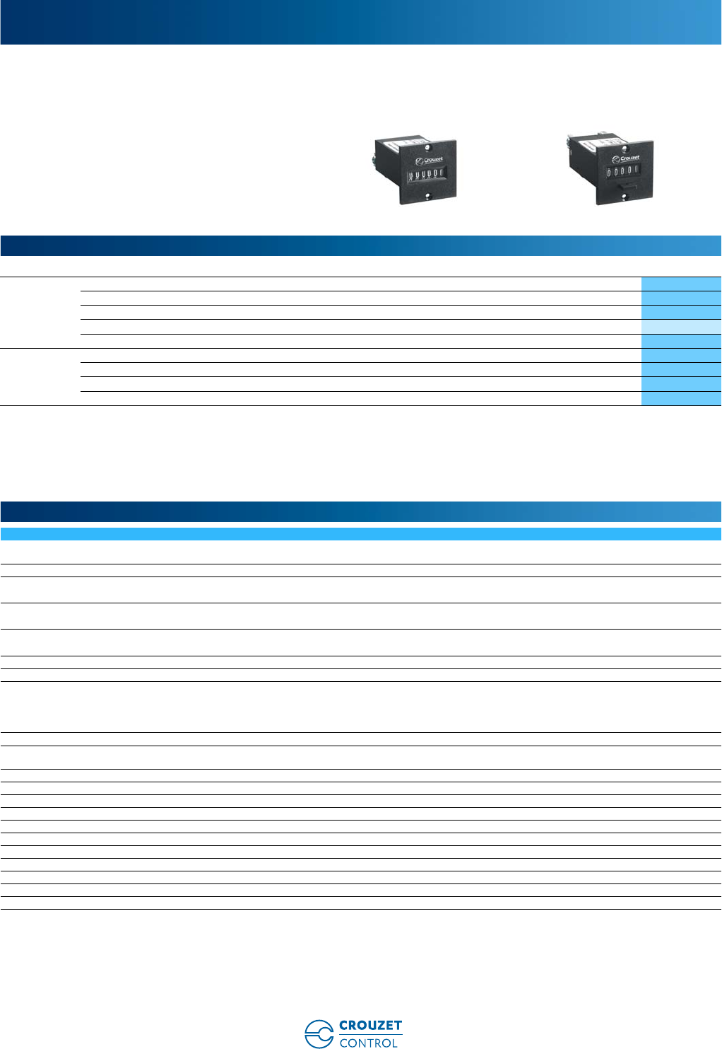
www.crouzet-control.com
72
1
➜ Impulse counters - CIM 36 x 37
■ 5 or 6 digits, height of digits 4 mm
■ With or without manual reset
■ White digits on a black background
Type Number of digits Operating frequency (Hz) Voltages Code
Without
manual reset
6 50 / 60 230 Va99776601
6 50 / 60 115 Va99776602
6 50 / 60 24 Va99776604
6Vc110 Vc99776605
6Vc24 Vc99776607
With manual
reset
5 50 / 60 230 Va99776610
5 50 / 60 115 Va99776611
5 50 / 60 24 Va99776613
5Vc24 Vc99776616
General characteristics
Counting capacity 999.999 impulses without manual reset
99.999 impulses with manual reset
Height digits (mm) 4
Max. count rate Va ➞18 impulses/s
Vc ➞25 impulses/s
Min. count rate Va ➞28 ms
Vc ➞20 ms
Min pause time between 2 pulses Va ➞28 ms
Vc ➞20 ms
Max. pulse length (count coil) Unlimited
Voltage variation + 10% / -15% Un
Consumption 24 Va / 115 Va: 1.1 VA
230 Va: 2.1 VA
110 Vc: 1 W
24 Vc: 0.8 W
Mechanical life count function (operations) > 50 x 106
Test voltage according to standard IEC 255-5 U < 60 V: 500 V
U > 60 V: 2 000 V
Protection Housing IP40
Degree of terminal protection IP00
Environmental protection Plated or stainless steel components
Maintenance None
Operating position Any
Temperature limits use (°C) - 10 ➞+60
Temperature limits stored (°C) - 40 ➞+80
Certifications CE
Connection 6.35 Faston connectors or screw terminals
Mounting 2 x 2.5 Ø screws - F90° on front face
Weight (g) 50
Electromechanical impulse counters
Part numbers
General characteristics
www.crouzet-control.com 73
2
9977660 - Rear faces Panel cut-out 9977660 - Rear faces
9977660 - 6 digits
9977661 - 5 digits
Dimensions (mm)
33,5
¯2,7
24
30
37
Ø2,5
36
30
49,3
6
2,5
8,5
23,5
20
37
2,5
36
30
54,1
6
2,5
8,5
23,5
20
6
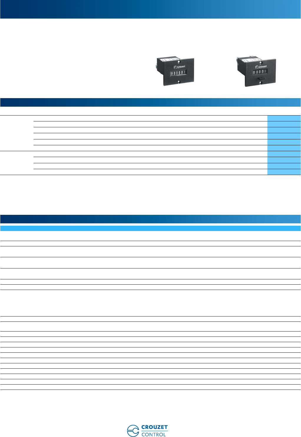
www.crouzet-control.com
74
1
➜ Impulse counters - CIM 36 x 48
■ 5 or 6 digits, height of digits 4 mm
■ With or without manual reset
■ White digits on a black background
Type Number of digits Operating frequency (Hz) Voltages Code
Without
manual reset
6 50 / 60 230 Va99776701
6 50 / 60 115 Va99776702
6 50 / 60 24 Va99776704
6Vc110 Vc99776705
6Vc24 Vc99776707
6Vc48 Vc99776736
With manual
reset
5 50 / 60 230 Va99776710
5 50 / 60 115 Va99776711
5 50 / 60 24 Va99776713
5Vc24 Vc99776716
General characteristics
Counting capacity 999.999 impulses without manual reset
99.999 impulses with manual reset
Height digits (mm) 4
Max. count rate Va ➞18 impulses/s
Vc ➞25 impulses/s
Min. count rate Va ➞28 ms
Vc ➞20 ms
Min pause time between 2 pulses Va ➞28 ms
Vc ➞20 ms
Max. pulse length (count coil) Unlimited
Voltage variation + 10% / -15% Un
Consumption 24 Va / 115 Va: 1.1 VA
230 Va: 2.1 VA
110 Vc: 1 W
48 Vc: 0.8 W
24 Vc: 0.8 W
Mechanical life count function (operations) > 50 x 106
Test voltage according to standard IEC 255-5 U < 60 V: 500 V
U > 60 V: 2 000 V
Protection Housing IP40
Degree of terminal protection IP00
Environmental protection Plated or stainless steel components
Maintenance None
Operating position Any
Temperature limits use (°C) -10 ➞+60
Temperature limits stored (°C) -40 ➞+80
Certifications CE
Connection 6.35 Faston connectors or screw terminals
Mounting 2 x 2.5 Ø screws - F90° on front face
Weight (g) 50
Electromechanical impulse counters
Part numbers
General characteristics
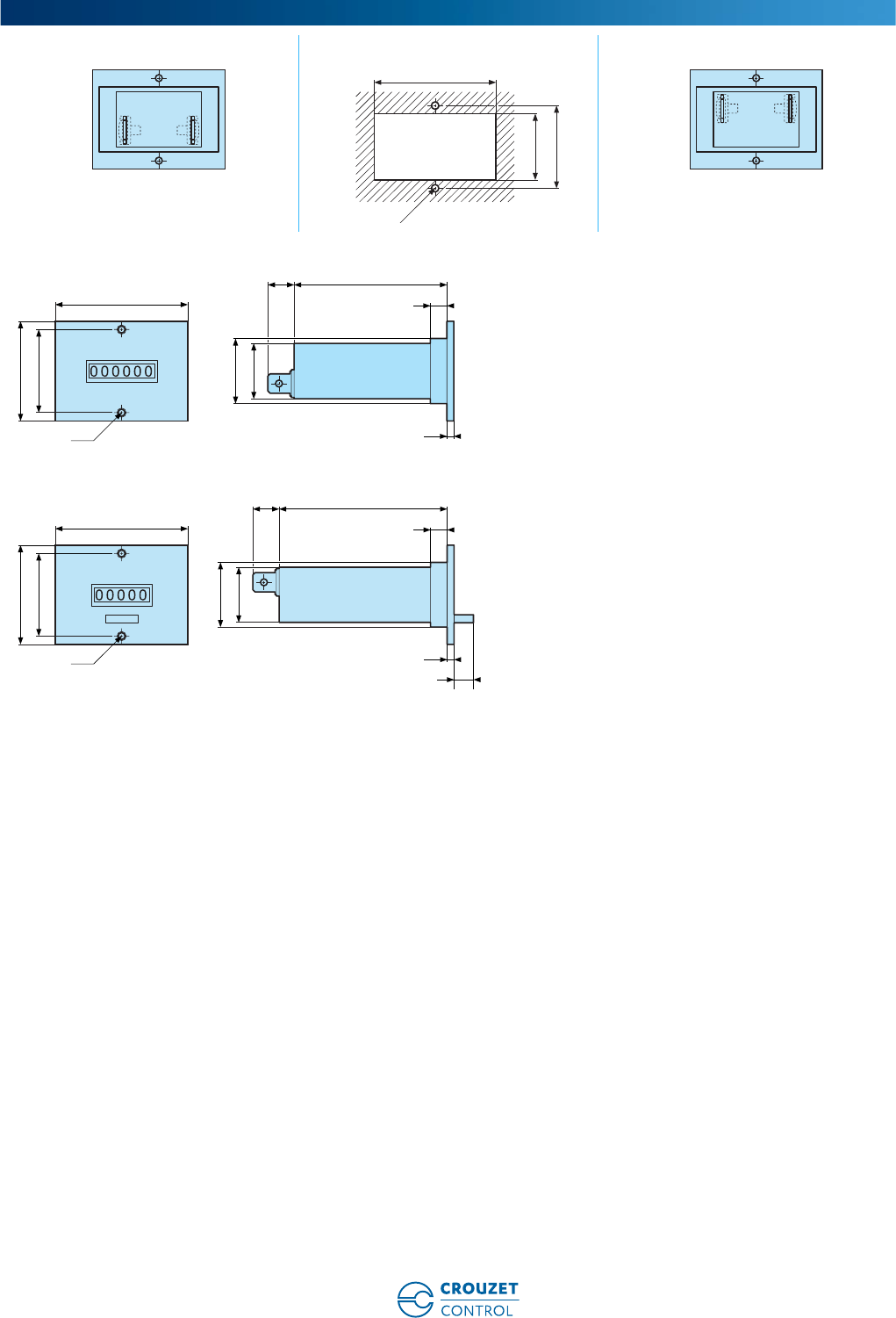
www.crouzet-control.com 75
2
9977670/3 - Rear faces Panel cut-out 9977671 - Rear faces
9977670/3 - 6 digits
9977671 - 5 digits
Dimensions (mm)
44
Ø2,7
24
30
48
Ø2,5
36
30
49,3
6
2,5
8,5
23,5
20
48
Ø2,5
36
30
54,1
6
2,5
8,5
23,5
20
6
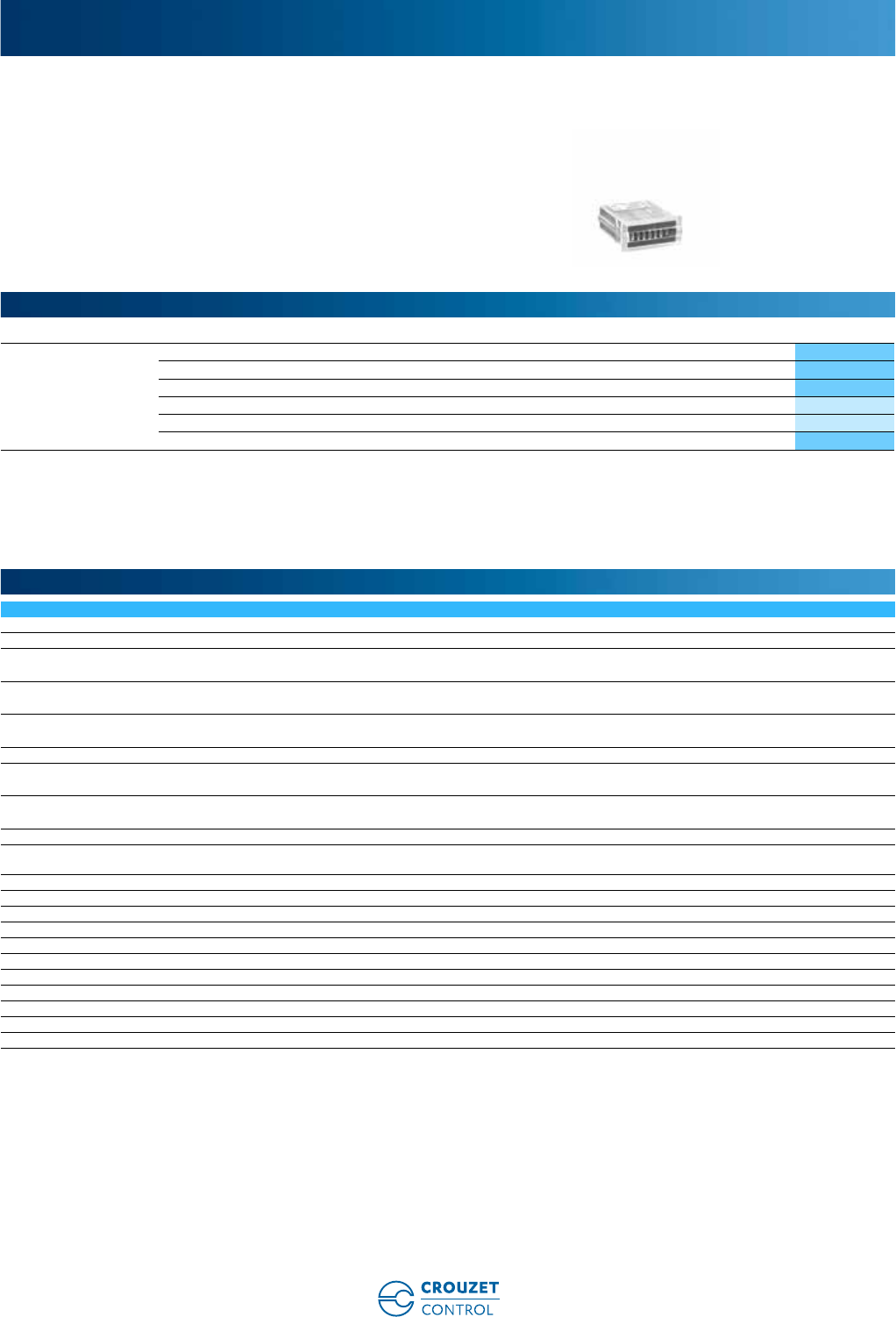
www.crouzet-control.com
76
1
➜ Impulse counters with built-in fixing clip - 15 x 32 - CIM15
■ 7 digits, height of digits 4 mm
■ Without manual reset
■ White digits on a black background
■ Compact size
■ Built-in fixing clip
■ IP65 (panel only)
Type Operating frequency (Hz) Voltages Code
Without manual reset 50 / 60 24 Va99778710
50 / 60 115 Va99778712
50 / 60 230 Va99778714
Vc5 Vc99778805
Vc12 Vc99778806
Vc24 Vc99778810
*9.999.999
Counting capacity 9.999.999
Height digits (mm) 4
Max. count rate Va ➞10 impulses/s
Vc ➞10 impulses/s (except for 99778810: up to 25 impulses/s)
Min. count rate Va ➞50 ms
Vc ➞50 ms
Min pause time between 2 pulses Va ➞50 ms
Vc ➞50 ms
Max. pulse length (count coil) Unlimited
Voltage variation Vc: ± -10%
Va: ± -10%
Consumption Va: 800 mVA
Vc: 50 mW
Mechanical life count function (operations) > 50 x 106
Test voltage according to standard IEC 255-5 U < 60 V: 500 V
U > 60 V: 2 000 V
Protection Housing IP65 panel only
Degree of terminal protection IP00
Environmental protection Plated or stainless steel components
Maintenance None
Operating position Any
Temperature limits use (°C) -10 ➞+60
Temperature limits stored (°C) -40 ➞+80
Certifications UL (pending) - CE
Connection Flying leads
Mounting Built-in fixing clip
Weight (g) 20
Electromechanical impulse counters
Part numbers
General characteristics
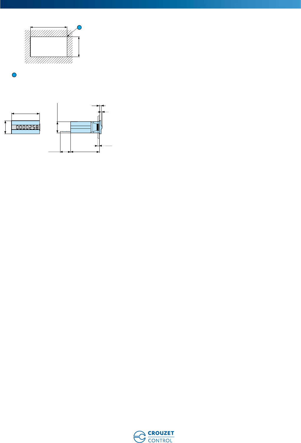
www.crouzet-control.com 77
2
Panel cut-out
R max: 0.5 mm
997787/8 - 7 digits
Dimensions (mm)
30
13+0,5
+0,3
1
1
32
15
max.3
150 32,7
1,1
2
13 x 29.9
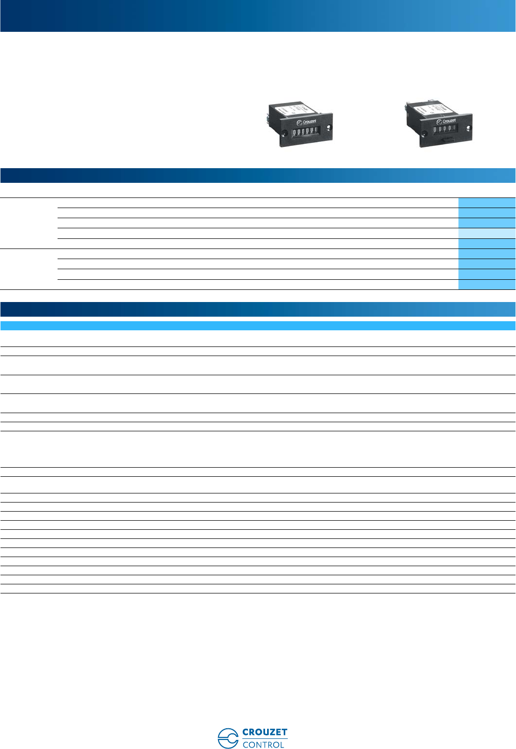
www.crouzet-control.com
78
1
➜ Screw-fixing impulse counters - CIM 24 x 48
■ 5 or 6 digits, height of digits 4 mm
■ With or without manual reset
■ White digits on a black background
Type Number of digits Operating frequency (Hz) Voltages Code
Without
manual reset
6 50 / 60 230 Va99776901
6 50 / 60 115 Va99776902
6 50 / 60 24 Va99776904
6Vc110 Vc99776905
6Vc24 Vc99776907
With manual
reset
5 50 / 60 230 Va99776921
5 50 / 60 115 Va99776922
5 50 / 60 24 Va99776924
5Vc24 Vc99776927
General characteristics
Counting capacity 999.999 impulses without manual reset
99.999 impulses with manual reset
Height digits (mm) 4
Max. count rate Va ➞18 impulses/s
Vc ➞25 impulses/s
Min. count rate Va ➞28 ms
Vc ➞20 ms
Min pause time between 2 pulses Va ➞28 ms
Vc ➞20 ms
Max. pulse length (count coil) Unlimited
Voltage variation + 10% / -15% Un
Consumption 24 Va / 115 Va: 1.1 VA
230 Va: 2.1 VA
110 Vc: 1 W
24 Vc: 0.8 W
Mechanical life count function (operations) 50 x 106
Test voltage according to standard IEC 255-5 U < 60 V: 500 V
U > 60 V: 2 000 V
Protection Housing IP40
Degree of terminal protection IP00
Environmental protection Plated or stainless steel components
Maintenance None
Operating position Any
Temperature limits use (°C) -10 ➞+60
Temperature limits stored (°C) -40 ➞+80
Certifications CE
Connection 6.35 Faston connectors or screw terminals
Mounting 2 M3 screws - F90° on front face
Weight (g) 50
Electromechanical impulse counters
Part numbers
General characteristics
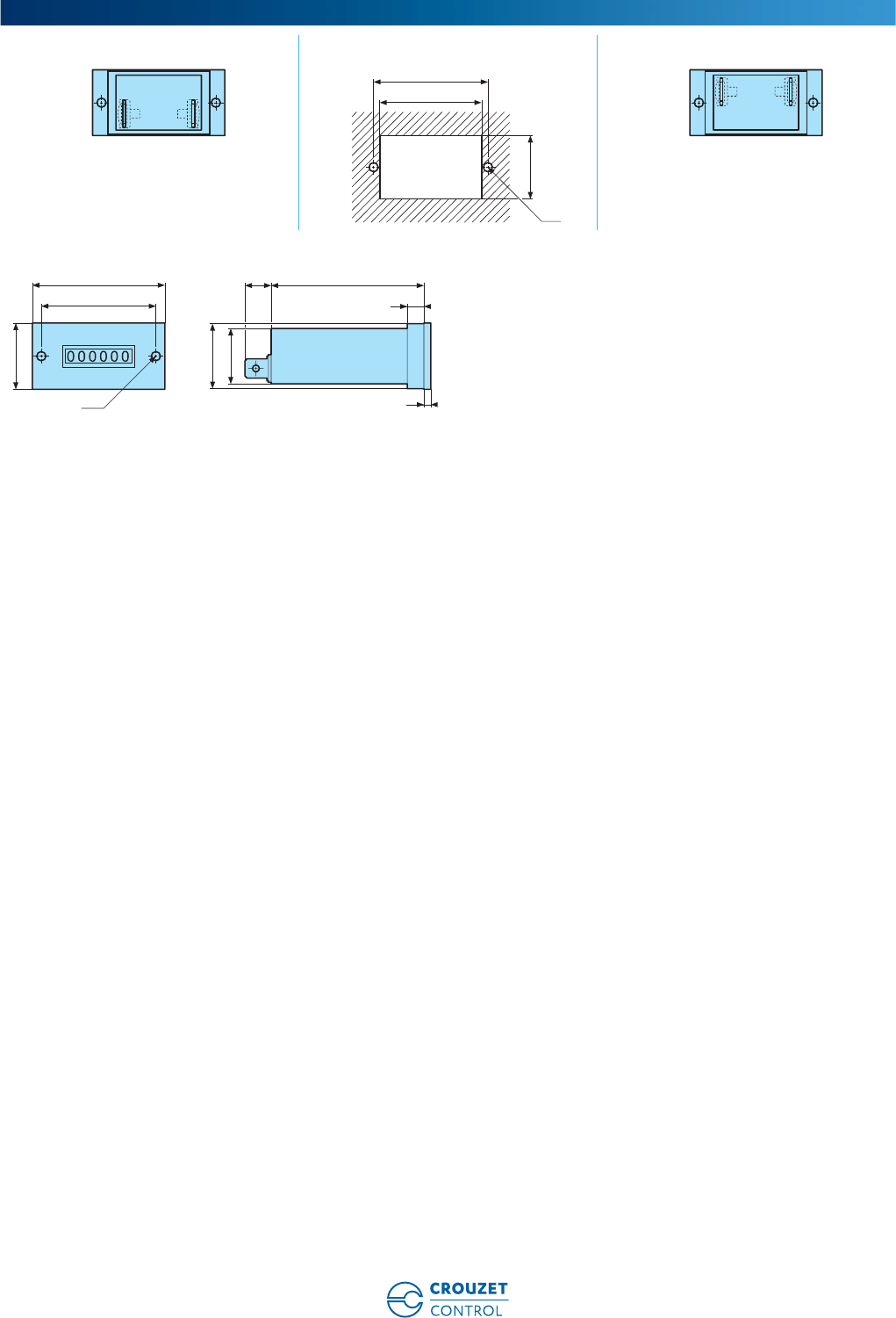
www.crouzet-control.com 79
2
9977690 - Rear faces Panel cut-out 9977692 - Rear faces
9977690 - 6 digits
Dimensions (mm)
37
41,5
M
3
23
48
Ø3,2
24
41,5
49,3
6
3
8,5
22,5
20
Ref.: 6711106A EN | 02/2016 - Photos: Ginko, Daniel lattard, Schneider Electric, Fotolia, Shutterstock
Warning:
The product information contained in this catalogue is given purely as information and does not constitute a representation, warrantly or any form of contractual commitment. Crouzet
Automatismes SAS and its subsidiaries reserve the right to modify their products without notice. It is imperative that we should be consulted over any particular use or application of our
products and it is the responsability of the buyer to establish, particularly through all the appropriate tests, that the product is suitable for the use or application. Under no circumstances
will our warranty apply, nor shall we be held responsible for any application (such as any modication, addition, deletion, use in conjunction with other electrical or electronic components,
circuits or assemblies, or any other unsuitable material or substance) which has not been expressly agreed by us prior to the sale of our products.
AMERICAS EUROPE / MIDDLE EAST / AFRICA ASIA / PACIFIC
WWW.CROUZET-CONTROL.COM WWW.INNOVISTASENSORS.COM
SPAIN / PORTUGAL
InnoVista Sensors™
C/Lleó, 11-13 2º4ª
08911 Badalona - Barcelona
ESPAÑA
Tel.: +34 (93) 484 39 70
Fax: +34 (93) 484 39 73
atencionalcliente@crouzet.com
SWITZERLAND
InnoVista Sensors™
Gewerbepark - Postfach 56
5506 Mägenwil - SCHWEIZ
Tel.: +49 (0) 2103/980-0
Fax: +49 (0) 2103/980-222
kundenservice@crouzet.com
THE NETHERLANDS
InnoVista Sensors™
Industrieweg 17
2382 NR Zoeterwoude
NEDERLAND
Tel.: +31 (0) 71-581 20 30
Fax: +31 (0) 71-541 35 74
klantenservice@crouzet.com
COUNTRIES NOT LISTED
InnoVista Sensors™
2 rue du Docteur Henri Abel,
CS 60059
26902 Valence Cedex 9
FRANCE
Tel.: +33 (0) 475 802 102
Fax: +33 (0) 475 828 900
customer.relation@crouzet.com
CANADA
InnoVista Sensors™
1461 Lawrence Drive
Thousand Oaks, CA 91320
USA
Tel.: +1 (800) 677 5311
Fax: +1 (800) 677 3865
customer.service@us.crouzet.com
MEXICO
InnoVista Sensors™
Calzada Zavaleta 2505-C
Santa Cruz Buenavista
Puebla, 72150 - MEXICO
Tel.: +52 (222) 409 7000
mexico@crouzet.com
USA
InnoVista Sensors™
1461 Lawrence Drive
Thousand Oaks, CA 91320
USA
Tel.: +1 (800) 677 5311
Fax: +1 (800) 677 3865
customer.service@us.crouzet.com
COUNTRIES NOT LISTED
InnoVista Sensors™
1461 Lawrence Drive
Thousand Oaks, CA 91320
USA
Tel.: +1 (800) 677 5311
Fax: +1 (800) 677 3865
customer.service@us.crouzet.com
BELGIUM
InnoVista Sensors™
Dieweg 3 B
1180 Uccle - BELGIQUE
Tel.: +32 (0) 2 462 07 30
Fax: +32 (0) 2 461 00 23
klantenservice@crouzet.com
FRANCE
InnoVista Sensors™
2 rue du Docteur Henri Abel,
CS 60059
26902 Valence Cedex 9
FRANCE
Tel.: +33 (0) 475 802 101
Fax: +33 (0) 475 828 900
relationclient@crouzet.com
GERMANY / AUSTRIA
InnoVista Sensors™
Otto-Hahn-Str. 3
40721 Hilden
DEUTSCHLAND
Tel.: +49 (0) 2103/980-0
Fax: +49 (0) 2103/980-222
kundenservice@crouzet.com
ITALY
InnoVista Sensors™
Via Viganò De Vizzi, 93/95
20092 Cinisello Balsamo (Mi)
ITALIA
Tel.: +39 (02) 66 599 211
Fax: +39 (02) 66 599 218
assistenzaclienti@crouzet.com
www.crouzet.it
CHINA
InnoVista Sensors™
11th oor, Chang Feng
International Tower,
89 Yunling Road (East),
Putuo District,
Shanghai 200 062 - CHINA
Tel.: +86 (21) 8025 7166
Fax: +86 (21) 6107 1771
china@crouzet.com
INDIA
InnoVista Sensors™
4th oor, Trident Towers, #23 100
Feet Ashoka Pillar Road,
2nd Block, Jaynagar
Bangalore 560 011 - INDIA
Tel.: +91 (80) 4113 2204/05
Fax: +91 (80) 4113 2206
india@crouzet.com
SOUTH KOREA
InnoVista Sensors™
14F, Kbiz DMC Tower,
189, Seongam-Ro, Mapo-Gu,
Seoul 121-904
SOUTH KOREA
Tel.: +82 (2) 2629 8312
Fax: +82 (2) 2630 9800
korea@crouzet.com
EAST ASIA PACIFIC
InnoVista Sensors™
10/F, Wharf T&T Centre, Harbour
City, 7 Canton Road, Tsim Sha Tsui,
Kowloon, HONG KONG
Tel.: +86 (21) 8025 7177
Fax: +86 (21) 6107 1771
eap@crouzet.com
