Crouzet User Guide Dcmind Brushless Tni21 EN
2016-08-19
: Crouzet Crouzet User-Guide Dcmind Brushless Tni21 En Crouzet_user-guide_Dcmind_brushless_tni21_EN library assets
Open the PDF directly: View PDF ![]() .
.
Page Count: 39
WWW.CROUZET-MOTORS.COM
TNi21 DCMIND BRUSHLESS
MOTORS
USER AND SAFETY MANUAL
07 April 2016 Page 1/38
TNi21 DCmind brushless motors
User and safety manual
Important notes
This manual is part of the product.
Read and follow the instructions in this manual.
Keep this manual in a safe place.
Give this manual and any documents relating to the product to anyone using the product.
Read and follow closely all the safety instructions in the "Before you start - Safety information"
section.
Please see the current catalogue for the product's technical specification.
We reserve the right to make modifications without prior notice.
Unless otherwise stated in writing by Crouzet Automatismes, any use of the products described
herein automatically signifies unconditional acceptance by the user of our general conditions of sale
and the waiver of any stipulations which might be printed on its orders or correspondence. Crouzet
Automatismes accepts no liability for any malfunction or damage caused by the user, due to the use
of this manual or the instructions herein.

TNi21
07 April 2016 Page 2/38
Table of contents
1. Introduction ................................................................................................................................................ 5
1.1. Motor family ....................................................................................................................................... 5
1.2. Features ............................................................................................................................................ 5
1.3. Options .............................................................................................................................................. 5
1.4. Identification label ............................................................................................................................. 5
1.5. Product coding .................................................................................................................................. 6
2. Before you start - Safety information ......................................................................................................... 7
2.1. Qualification of personnel .................................................................................................................. 7
2.2. Use for intended purpose .................................................................................................................. 7
2.3. Basic information ............................................................................................................................... 8
2.4. Standards and concepts ................................................................................................................... 9
3. Precautions for use at a mechanical level ............................................................................................... 10
3.1. Data specific to the motor shaft ...................................................................................................... 10
3.1.1. Force applied when pushing items on to the shaft ................................................................. 10
3.1.2. Radial load on the shaft .......................................................................................................... 10
3.2. Options ............................................................................................................................................ 11
3.2.1. Holding brake ......................................................................................................................... 11
3.2.2. Gearboxes .............................................................................................................................. 11
3.2.3. Others ..................................................................................................................................... 11
4. Installation ................................................................................................................................................ 12
4.1. Snapshot of the installation procedure ............................................................................................ 14
4.2. Electromagnetic compatibility, EMC ............................................................................................... 14
4.3. Before fitting .................................................................................................................................... 15
4.4. Fitting the motor .............................................................................................................................. 16
4.5. Electrical installation ........................................................................................................................ 17
4.5.1. Connecting the holding brake (option) ................................................................................... 19
4.6. Production connector ...................................................................................................................... 20
5. Switching on ............................................................................................................................................. 21
5.1. Preparations for switching on .......................................................................................................... 21
6. Product presentation ................................................................................................................................ 23
6.1. Description of the product ............................................................................................................... 23
6.2. TNI21 control electronics ................................................................................................................ 23
7. Technical characteristics ......................................................................................................................... 24
7.1. Electrical data .................................................................................................................................. 24
7.2. Generic data .................................................................................................................................... 24
7.3. Control logic bundle ........................................................................................................................ 25
7.4. Power supply cable ......................................................................................................................... 26
8. Motor electrical connection ...................................................................................................................... 27

TNi21
07 April 2016 Page 3/38
8.1. Power connection ............................................................................................................................ 27
8.1.1. Ballast circuit .......................................................................................................................... 27
8.1.2. Protection for EMC ................................................................................................................. 29
8.2. Protective devices ........................................................................................................................... 30
8.2.1. Voltage protection................................................................................................................... 30
8.2.2. Temperature protection .......................................................................................................... 30
8.2.3. Current limiting ....................................................................................................................... 31
8.3. Connecting inputs/outputs............................................................................................................... 31
8.3.1. Equivalent inputs diagram ...................................................................................................... 31
8.3.2. Equivalent outputs diagram .................................................................................................... 32
9. Operating mode ....................................................................................................................................... 33
9.1. Preliminaries ................................................................................................................................... 33
9.2. Functions associated with inputs .................................................................................................... 33
9.2.1. Function E1 - On / Off ............................................................................................................ 33
9.2.2. Function E2 - Direction of rotation .......................................................................................... 33
9.2.3. Function E3 - Speed set-point ................................................................................................ 33
9.2.4. Function E4 - Torque limiter set-point .................................................................................... 34
9.3. Functions associated with outputs .................................................................................................. 34
9.3.1. Function S1 - Encoder output ................................................................................................. 34
9.3.2. Function S2 - Torque limiter output ........................................................................................ 34
9.3.3. Function S3 - Actual direction of rotation output .................................................................... 34
9.4. SAFE mode ..................................................................................................................................... 35
10. Diagnostics and troubleshooting ......................................................................................................... 35
10.1. Mechanical faults ............................................................................................................................ 35
10.2. Electrical problems .......................................................................................................................... 35
11. Service, maintenance and problem solving ........................................................................................ 36
11.1. Addresses of after-sales service points .......................................................................................... 36
11.2. Storage ............................................................................................................................................ 36
11.3. Maintenance .................................................................................................................................... 36
11.4. Replacing the motor ........................................................................................................................ 37
11.5. Shipping, storage, disposal ............................................................................................................. 37
11.6. Terms and abbreviations ................................................................................................................. 38
TNi21
07 April 2016 Page 4/38
About this manual
This manual applies to TNI21 DCmind brushless products:
801400TNI21, 801495TNI21, 801496TNI21, 801410TNI21,
801800TNI21, 801896TNI21, 801897TNI21, 801810TNI21,
802800TNI21, 802896TNI21, 802897TNI21, 802810TNI21,
Reference source for manuals
Manuals are available to download from the Internet at the following address
http://www.crouzet.com/
Units
By default, units rotate anti-clockwise.
Risk categories
In this manual, safety instructions are identified by warning symbols.
Safety instructions are divided into three risk categories, depending on the gravity of the situation.
DANGER
DANGER indicates an immediately dangerous situation, which, if
instructions are not followed, would inevitably result in a serious or
fatal accident.
WARNING
WARNING indicates a potentially dangerous situation which, if
instructions are not followed, could in certain cases result in a serious
or fatal accident or cause damage to equipment.
CAUTION
CAUTION indicates a potentially dangerous situation which, if
instructions are not followed, could in certain cases result in an
accident or cause damage to equipment.
TNi21
07 April 2016 Page 5/38
1. INTRODUCTION
1.1. Motor family
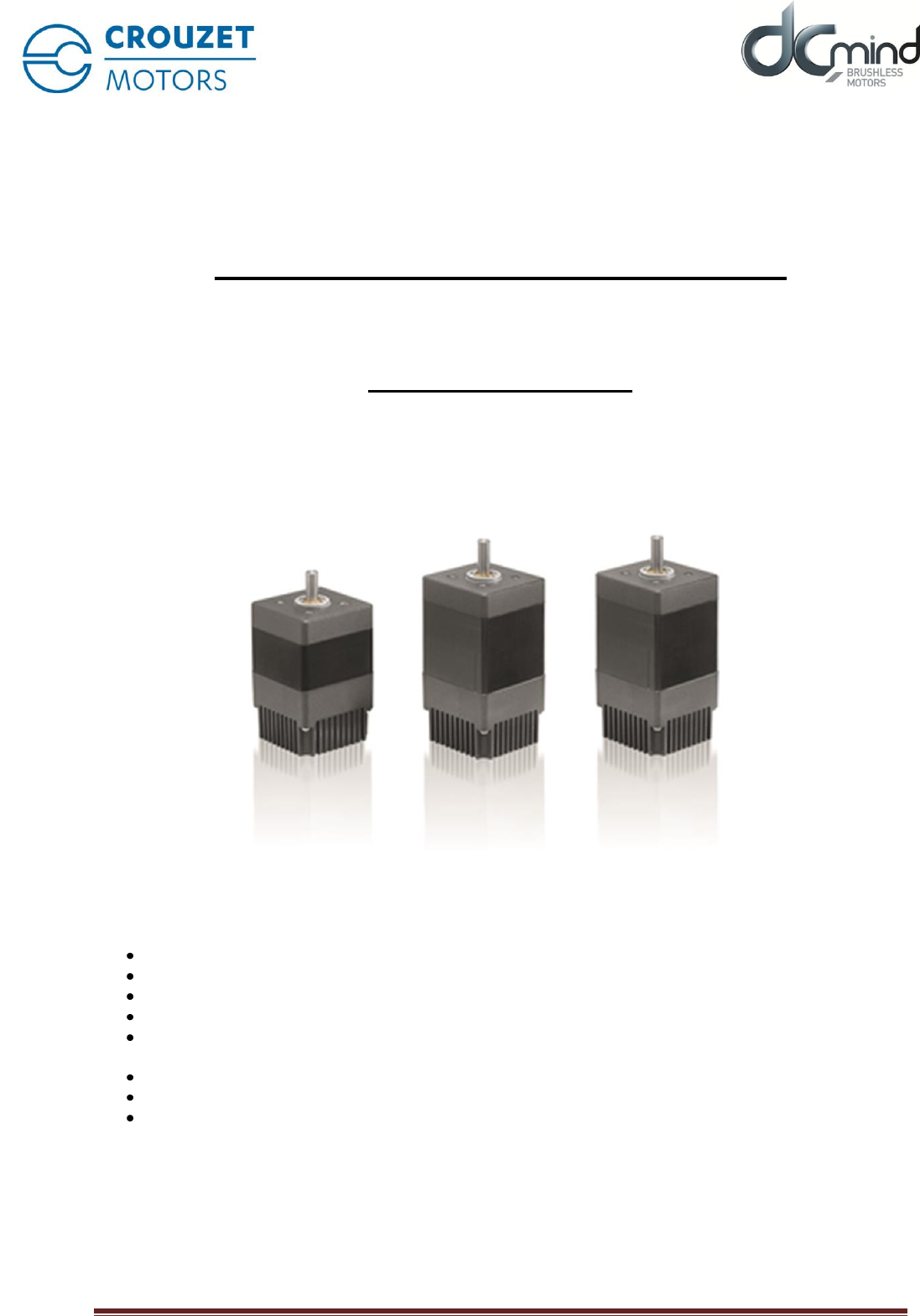
TNI21 DCmind brushless motors are direct current brushless motors with a built-in electronic control board.
1.2. Features
TNI21 DCmind brushless motors are intelligent servomotors for speed and torque control applications.
They are fitted with two unscreened cables as standard, one for power and one for control.
1.3. Options
Motors may be supplied with options such as:
a range of gearboxes
a holding brake in the event of loss of current
various motor output shaft versions
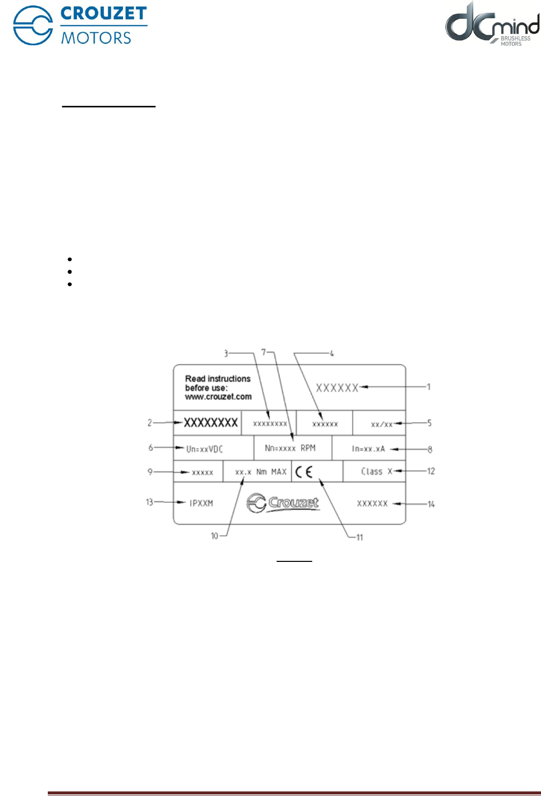
1.4. Identification label
The label carries the following information:
Figure 1
1. Product family code
2. Product reference
3. Reserved area
4. Area reserved for special customer markings
5. Date manufactured: week/year
6. Operating voltage
7. The motor's rated speed at 24V
8. The motor's rated current
9. Gear ratio (for versions with gearboxes)
10. Maximum nominal torque applicable to gearboxes (for versions with gearboxes).
11. Motor approvals.
12. Insulation system temperature class.
13. Degree of protection (sealing) of the product during operation (apart from the output shaft).
14. Country of manufacture

TNi21
07 April 2016 Page 6/38
1.5. Product coding
80 XX XX TNI21: Product family based on TNI21 electronics
PRODUCT REFERENCE
8
0
X
X
X
X
X
X
Motor
Type of stator:
14: 30 mm brushless stator
18: 50mm brushless stator
28: 50mm brushless stator
high torque
Gearboxes fitted:
00: no gearbox
10: RAD10 gearbox
95: P52 gearbox
96: P62 gearbox
97: P81 gearbox
Incrementing numbers

TNi21
07 April 2016 Page 7/38
2. BEFORE YOU START - SAFETY INFORMATION
2.1. Qualification of personnel
Only qualified personnel, familiar with and understanding the contents of this manual, are authorised to work
on and with this product.
Qualified personnel should have a sound knowledge of current standards, regulations and requirements with
regard to accident prevention, when carrying out work on or with the product.
Those personnel must have undergone safety training, so that they are able to detect and prevent any
associated danger.
By virtue of their professional training, knowledge and experience, these qualified personnel should be able
to provide warning or recognise potential dangers, that could be caused by use of the product, modifying its
settings or those of mechanical, electrical and electronic equipment in the installation in general.
2.2. Use for intended purpose
As stated in these instructions, this product is a component intended for use in an industrial environment
The safety instructions in force, specified conditions and technical characteristics must be respected at all
times.
Before using the product for the first time, a risk analysis should be carried out on its use in practice.
Depending on the result, any necessary safety measures should be taken.
Since the product is used as a component in an overall system, it is the user's responsibility to ensure the
safety of persons through the design of the overall system, e.g. machine design.
Use only original spare parts and accessories.
The product must not be used in an explosive atmosphere (Ex zone).
Any other use is considered as non-compliant and could cause danger.
Only duly qualified personnel are authorised to install, operate, maintain and repair electrical devices and
equipment.

TNi21
07 April 2016 Page 8/38
2.3. Basic information
DANGER
DANGER DUE TO ELECTRIC SHOCK, EXPLOSION OR EXPLOSION DUE TO AN
ELECTRICAL ARC
• Only qualified personnel, familiar with and understanding the contents of this
manual, are authorised to work on and with this product. Only qualified personnel
are authorised to install, adjust, repair and maintain it.
• The person/entity constructing the installation is responsible for compliance with
all applicable requirements and regulations concerning the earthing of the drive
system.
• It is the user's responsibility to determine whether it is necessary to earth the
motor, depending on its use.
• Do not touch unprotected live parts.
• Use only electrically insulated tools.
• AC voltages may flow along unused conductors in the motor cable. Isolate unused
conductors at both ends of the motor cable.
• The motor produces a voltage when the shaft rotates. Isolate the motor shaft from
any external power supply, before carrying out any work on the drive system.
– Switch off all connections
– Attach a "DO NOT SWITCH ON" sign on all switches.
– Prevent all switches from being re-engaged.
– Wait for the motor's internal capacitors to discharge.. Measure the voltage in the
power cable and check that it is less than 12V DC.
• Fit and close all protective covers before re-applying power..
Failure to take these precautions could result in death or serious injury.
TNi21
07 April 2016 Page 9/38
WARNING
LOSS OF CONTROL
• When designing the control of the installation, the manufacturer should keep in
mind the implications of a potential failure in control paths and, for certain critical
functions, provide a method for returning to a safe state during and after the failure
of a control path.
Examples of critical control functions are:
EMERGENCY STOP, restricting the final position, network interruption and re-
starting.
• Separate or redundant control paths must be available for critical functions.
• Follow accident prevention instructions and all applicable safety directives.
• Any installation in which the product described in this manual is used must be
carefully and minutely checked to ensure that it is operating correctly, before it is
switched on.
If these precautions are not taken, the result could be death or serious injury.
WARNING
UNBRAKED MOVEMENT
In the event of a loss of power to the power stage, the motor is no longer braked in
a controlled way and could cause damage.
• Prevent access to the risk area..
• If necessary, use a damped mechanical stop or a service brake.
If these precautions are not taken, the result could be death, serious injury or
damage to equipment.
2.4. Standards and concepts
This product complies with European ROHS Directive 2011/65/EC and is CE marked.
The product's electrical design complies with standards IEC 60335-1 and IEC 60950-1.
TNi21
07 April 2016 Page
10/38
3. PRECAUTIONS FOR USE AT A MECHANICAL LEVEL
3.1. Data specific to the motor shaft
3.1.1. Force applied when pushing items on to the shaft
WARNING
MECHANICAL CHARACTERISTICS OF THE MOTOR
Exceeding the maximum permitted force on the shaft will result in rapid
wearing of the bearings, a broken shaft or the deterioration of any
accessories (encoder, brake, etc.)
• Never exceed the max. permissible radial or axial forces on the
motor.
• Protect the shaft against impacts.
• When pushing items in to the shaft, do not exceed the maximum
permitted axial force.
If these precautions are not taken, the result could be death,
serious injury or damage to equipment.
The maximum force when pushing items on to the shaft is limited by the maximum permitted axial force
acting on the ball bearings.
This maximum axial force is given in the motor's data sheet.
Alternatively, the item to be attached can be secured by clamping, bonding or binding.
3.1.2. Radial load on the shaft
Figure 2
The point of application X of the radial force F depends on the size of the motor.
This information is shown in the motor's data sheet.
The maximum radial and axial loads should not be applied simultaneously, so as to maximise the motor's
service life.
F
X

TNi21
07 April 2016 Page
11/38
3.2. Options
3.2.1. Holding brake
TNI21 DCmind brushless motors can be fitted with a fail safe electromechanical brake.
The holding brake is designed to prevent the shaft from rotating when there is no power to the motor.
The holding brake has no safety function.
The "Connecting a holding brake" section describes how it should be controlled.
3.2.2. Gearboxes
TNI21 DCmind brushless motors may be fitted with various types of gearbox.
The gearboxes offered in the standard catalogue are planetary gearboxes, combining compactness with
strength, and worm gearboxes that provide output from the shaft at right angles to the motor shaft.
3.2.3. Others
Other types of adaptation are possible upon request. Please contact our sales department.
TNi21
07 April 2016 Page
12/38
4. INSTALLATION
In a general sense, motors should be installed in line with good industrial practice.
WARNING
CONSIDERABLE WEIGHT AND FALLING PARTS
The motor can weigh a lot.
• Take the motor's weight into consideration when fitting it.
• Fit the motor (tightening torque of screws) in such a way that it
cannot come adrift, even in the event of high levels of acceleration or
permanent vibration.
If these precautions are not taken, the result could be death,
serious injury or damage to equipment.
WARNING
STRONG ELECTROMAGNETIC FIELDS
Motors can generate powerful local electrical and magnetic fields.
They can cause sensitive equipment to fail.
• Keep persons wearing implants such as heart pacemakers away
from the motor.
• Do not position sensitive equipment in the immediate proximity of the
motor.
If these precautions are not taken, the result could be death,
serious injury or damage to equipment.
WARNING
UNEXPECTED BEHAVIOUR AS A RESULT OF DETERIORATION OR
FOREIGN BODIES
As a result of deterioration of the product, the presence of foreign
bodies or deposits or penetration by fluids, unexpected behaviour can
occur.
• Do not use damaged products..
• Do not allow any foreign body to enter the product.
• Check that seals and power cable glands are correctly fitted.
• Check that the plug protecting the motor's internal connector is fitted
correctly.
If these precautions are not taken, the result could be death,
serious injury or damage to equipment.

TNi21
07 April 2016 Page
13/38
WARNING
HOT SURFACES
The metal surface of the product can reach more than 70°C during
use.
Avoid all contact with the metal surface.
• Do not position inflammable or heat-sensitive components in
immediate proximity.
• Try to achieve an assembly that allows heat to dissipate efficiently.
If these precautions are not taken, the result could be injury or
damage to equipment.
WARNING
DETERIORATION OR DESTRUCTION OF THE MOTOR DUE TO OVER-
STRESSING
The motor is not designed to withstand loads. If the motor is stressed,
it could be damaged or even fall.
• Do not stand on the motor.
• Prevent the motor being used in any other way than its intended
purpose by taking protective measures and following the safety
instructions.
If these precautions are not taken, the result could be injury or
damage to equipment.
CAUTION
OVER-VOLTAGES
During braking phases, the motor generates over-voltages.
• Check that these over-voltages are acceptable to other equipment
connected to the same power supply.
• Preferably, use an external circuit, to limit over-volting
In cases where braking is used intensively.
If these precautions are not taken, the result could be injury or
damage to equipment.
TNi21
07 April 2016 Page
14/38
4.1. Snapshot of the installation procedure
The installation procedure is described in the follow sections:
Electromagnetic compatibility, EMC
Before fitting
Fitting the motor
Electrical installation
Check that these sections have been read and understood and that, subsequently, the motor has been
installed correctly.
4.2. Electromagnetic compatibility, EMC
DANGER
INTERFERENCE AFFECTING SIGNALS AND EQUIPMENT
Interference with signals can cause equipment to behave
unpredictably
• Wiring should be done in accordance with the EMC
recommendations specific to each device.
• Ensure that these EMC recommendations are followed correctly.
If these precautions are not taken, the result could be death,
serious injury or damage to equipment.
Recommendations with regard to EMC: installing the motor's power supply wiring.
At the wiring planning stage, consider that the motor's power supply wiring must be installed isolated from
network or signal transmission cables.
Take the following measures with regard to EMC.
EMC measures
Effect
Keep cables as short as possible.
Do not install loops of unused cable.
Reduce interference, capacitive and inductive
couplings.
Earth the product.
Reduce emissions; increase immunity to
interference,
Where shielded cables are used, the cable
shielding should be fitted to the widest possible
surface area. Use cable clamps and earth bands.
Reduce emissions.
Position the motor's power supply wires separate
from cables that carry signals or use screening
plates.
Reduce mutual interference
If screened cables are used, fit them without an
isolation point. 1)
Reduce radiating interference.
1) Where the installation requires a cable to be cut, cables must be connected at the isolation point via a shielded cable inside a
metal enclosure.
Equipotential link conductors
Where screened cables are used, differences in voltage can cause currents not permitted in screened
cables. Fit equipotential link conductors to reduce current in screened cables.
TNi21
07 April 2016 Page
15/38
4.3. Before fitting
Look for damage
Damaged drive systems should not be fitted or used.
Check the drive system before fitting and look for visible signs of damage.
Cleaning the shaft
On leaving the factory, the ends of the motor shafts are coated with film of oil.
Where transmission devices are to be fitted by bonding, it may be necessary to remove that oil film and
clean the shaft. Where necessary, use degreasing products recommended by the manufacturer of the
bonding adhesive.
Avoid all contact between the skin and sealing materials and the cleaning product used.
Fitting surface for the flange
The fitting surface must be stable, flat and clean.
On the installation side, ensure compliance with all dimensions and tolerances.
Specification for power supply wires.
The power supply wires for the motor and its accessories must be selected with care according to their
length, the motor's supply voltage, the ambient temperature, the current passing through them and their
environment.
WARNING
DETERIORATION AND FIRE FOLLOWING INCORRECT INSTALLATION
Forces and movement in cable glands can damage cables.
• Comply with the stated bend radius
• Avoid subjecting cable glands to forces or movement.
• Secure supply cable close to cable glands using a strain relief clamp.
If these precautions are not taken, the result could be injury or
damage to equipment.
TNi21
07 April 2016 Page
16/38
4.4. Fitting the motor
DANGER
HOT SURFACES
The surface of the motor can reach more than 70°C during use.
• Avoid contact with hot surfaces.
• Do not position inflammable or heat-sensitive components in
immediate proximity.
• Try to achieve an assembly that allows heat to dissipate efficiently.
• Run a test to check the temperature.
If these precautions are not taken, the result could be injury or
damage to equipment.
WARNING
In rare cases, electrostatic discharges (ESD) on the shaft can cause
faults in the encoding system and unexpected movements of the
motor.
• Use conductive components, e.g. anti-static belts or other
appropriate measures to prevent any static charge due to movement.
WARNING
UNINTENDED BEHAVIOUR DUE TO MECHNANICAL DETERIORATION OF
THE MOTOR
Exceeding the maximum permissible forces on the shaft will result in
rapid wear of the bearings, a broken shaft or damage to the internal
encoder.
• Never exceed the max. permissible radial or axial forces on the
motor.
• Protect the shaft against impacts.
• When pushing items on to the shaft, do not exceed the maximum
permitted axial force.
If these precautions are not taken, the result could be death,
serious injury or damage to equipment.
TNi21
07 April 2016 Page
17/38
Installation position
The motor can be installed in any position.
Installation
When fitting the motor on the flange, it must be aligned precisely, both axially and radially. All securing
screws must be tightened to the torque prescribed by the application, taking care not to cause any warping.
Fitting transmission devices
Fitting transmission devices incorrectly could damage the motor.
Transmission devices such as pulleys and gears must be fitted with reference to the maximum axial and
radial forces specified in the data sheet for each motor.
Follow the manufacturer's fitting instructions for each transmission device.
The motor and transmission device must be aligned accurately, both radially and axially. Any failure to do so
will result in erratic operation, damage to bearings and a high level of wear.
4.5. Electrical installation
These motors are not designed to be connected directly to the electrical system.
It is the installer's responsibility to specify the electrical protection to be deployed with regard to the
regulations applicable to the field of use of the final product.
For the supply to the power part, we recommend the use of a stabilised double-insulated power supply unit.
The motor's power stage is not protected against reversed polarity.
The motor is said to be regenerative, i.e. it can feed back energy to the power supply during braking phases.
Voltage surges created in this way can reach levels that risk damaging the motor itself or to devices
connected to the same power supply.
DANGER
ELECTRIC SHOCK
High voltages can occur unexpectedly at the motor connection.
• The motor produces a voltage when the shaft rotates. Isolate the
motor shaft from any external driving force before doing any work on
the drive system.
• The system's manufacturer is responsible for complying with all the
rules applicable to the earthing of the drive system.
Failure to take these precautions could result in death or serious
injury.
WARNING
UNEXPECTED MOVEMENT
Drives may move unexpectedly, due to an incorrect connection or
some other error.
• Only start the installation if there is no person or obstacle inside the
danger zone.
• Make initial test movements with no load connected.
• Do not touch the motor shaft or connected drive components.
If these precautions are not taken, the result could be death,
serious injury or damage to equipment.
TNi21
07 April 2016 Page
18/38
WARNING
OVER-VOLTAGES
During braking phases, the motor generates over-voltages.
• Check that these over-voltages are acceptable to other equipment
connected to the same power supply.
• Preferably use an external circuit, to limit over-volting
In cases where braking is used intensively.
If these precautions are not taken, the result could be
death, serious injury or damage to equipment.
CAUTION
FIRE DUE TO POOR CONTACT
The connection terminals to the motor could heat up and the contacts
melt due to electrical arcing, if the connector is not properly plugged in.
• Poor connections can cause heating due to electrical arcing.
If these precautions are not taken, the result could be injury or
damage to equipment.
CAUTION
REVERSED POLARITY COULD DESTROY THE PRODUCT
Incorrectly connecting the power can result in reversed polarity and the
destruction of the electronic board inside the motor.
• Check that the power connection is correct.
If these precautions are not taken, the result could be injury or
damage to equipment.
Connecting the protective conductor
It is the installer's responsibility to determine the necessity to earth the motor.
This must be done via the mounting flange.
Under no circumstances connect or disconnect the product's power supply wires while they are live.
TNi21
07 April 2016 Page
19/38
4.5.1. Connecting the holding brake (option)
WARNING
LOSS OF BRAKING FORCE DUE TO WEAR OR HIGH TEMPERATURE
Application of the holding brake while the motor is rotating can cause
rapid wear and loss of braking force.
• Do not use the brake as a service brake.
• Note that an "emergency stop" can also cause wear.
If these precautions are not taken, the result could be death,
serious injury or damage to equipment.
WARNING
UNEXPECTED MOVEMENT
Releasing the holding brake can cause unexpected movement in the
installation.
• Take care that this does not cause any damage.
• Only run tests if there is no person or obstacle inside the danger
zone.
If these precautions are not taken, the result could be death,
serious injury or damage to equipment.
CAUTION
MALFUNCTION OF THE HOLDING BRAKE DUE TO AN INAPPROPRIATE
VOLTAGE
• If the voltage is too low, the holding brake cannot release itself and
that will cause wear.
• If voltages are higher than specified, the holding brake will suffer
excessive heating.
If these precautions are not taken, the result could be injury or
damage to equipment.
A motor with a holding brake requires a suitable control logic which releases the brake when rotational
movement starts and which grips the motor shaft in time when the motor stops.
TNi21
07 April 2016 Page
20/38
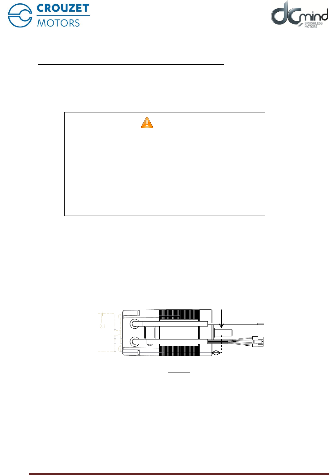
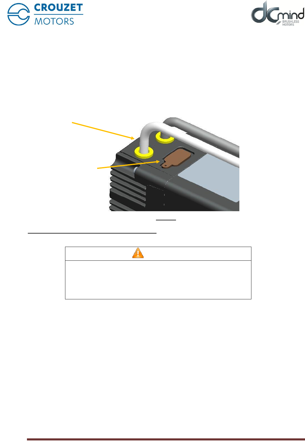
4.6. Production connector
The motor is fitted with a silicone plug, as shown in the image below.
It protects the connector used during the motor's manufacture.
This connector is not intended to be accessed by users of the product.
If the plug is removed, the motor will no longer be sealed, allowing fluids and particles to enter the motor,
potentially destroying it or causing it to malfunction.
Figure 3
The plug should never be removed by the user.
CAUTION
LOSS OF SEALING
The plug keeps the motor sealed.
• Do not remove the plug.
If these precautions are not taken, the result could be injury or
damage to equipment.
Plug
Enclosure
TNi21
07 April 2016 Page
21/38
5. SWITCHING ON
5.1. Preparations for switching on
Before switching on:
Check that the mechanical installation is correct.
Check that the electrical installation has been done professionally: in particular, check the connections
on protective conductors and earth connections. Ensure that all connections are correct and sound and
that screws are properly tight.
Check the ambient conditions and conditions for use: ensure that the prescribed ambient conditions are
met and that the drive solution complies with the intended conditions for use.
Check that any transmission devices already fitted are balanced and accurately aligned.
Check that the conditions of use do not cause any abnormal over-voltages for the product or the
application.
Check that the holding brake can support the maximum load. Check that after the braking voltage is
applied, the holding brake releases correctly. Ensure that the holding brake is properly released prior to
movement starting.
Check that the connector protection plug is in place.
WARNING
UNEXPECTED MOVEMENT
Drives may move unexpectedly, due to an incorrect connection or
some other error.
• Check the wiring.
• Only start the installation if there is no person or obstacle inside the
danger zone.
• Make initial test movements with no load coupled.
• Do not touch the motor shaft or associated drive components.
If these precautions are not taken, the result could be death,
serious injury or damage to equipment.
WARNING
ROTATING PARTS
Rotating parts can cause injury or catch clothing or hair. Loose parts or
unbalanced parts can be thrown off.
• Check that all rotating parts are secure.
• Fit a guard over rotating parts.
If these precautions are not taken, the result could be death,
serious injury or damage to equipment.
TNi21
07 April 2016 Page
22/38
WARNING
FALLING PARTS
Reactive torque could cause the motor to move, tip or fall.
• Secure the motor firmly, so that it cannot come loose due to severe
acceleration.
If these precautions are not taken, the result could be death,
serious injury or damage to equipment.
CAUTION
HOT SURFACES
The surface of the motor can reach more than 70°C during use.
• Avoid contact with hot surfaces.
• Do not position inflammable or heat-sensitive components in
immediate proximity.
• Try to achieve an assembly that allows heat to dissipate efficiently.
• Run a test to check the temperature.
If these precautions are not taken, the result could be injury or
damage to equipment.
CAUTION
OVER-VOLTAGES
During braking phases, the motor generates over-voltages.
• Check that these over-voltages are acceptable to other equipment
connected to the same power supply.
• Preferably use an external circuit, to limit over-volting
In cases where braking is used intensively.
If these precautions are not taken, the result could be injury or
damage to equipment.
TNi21
07 April 2016 Page
23/38
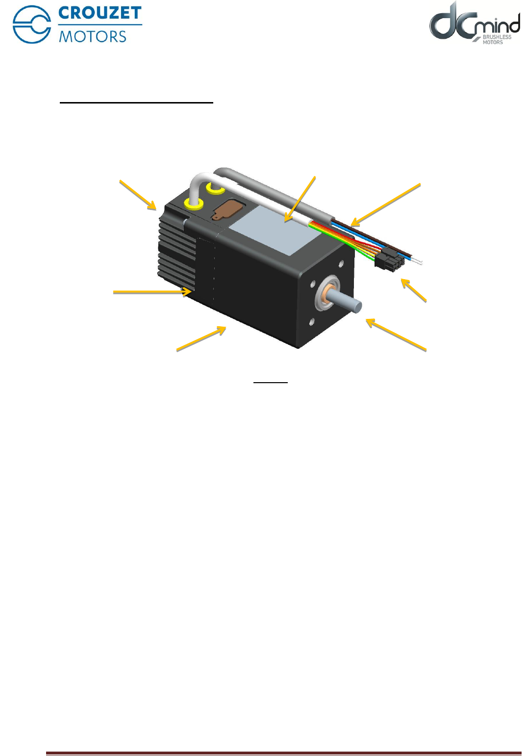
6. PRODUCT PRESENTATION
6.1. Description of the product
6.2. TNI21 control electronics
The TNI21 electronic board contains control electronics for brushless motors and is built into the body of the
motor.
These electronics provide:
• Motor power control in trapeze mode ("6 steps").
• A speed control
• Torque limiting control
• Management of the four inputs and three outputs that control the motor:
o Two 10-bit or PWM analogue control inputs
Speed set-point
Torque limiting
o Two switching inputs
On/off
Direction of rotation
o One encoder output
12 points per revolution for 80140 and 80180 motors
24 points per revolution for 80280 motors
o One 'torque limit reached' switching output
o One actual direction of rotation switching output
Label
8-contact logic connector
(Inputs/Outputs)
Power supply
(Power and Logic)
Output axis
No power rear brake
(Optional)
Brushless motor
TNI21 integrated
electronics
Figure 4

TNi21
07 April 2016 Page
24/38
7. TECHNICAL CHARACTERISTICS
7.1. Electrical data
Maximum product characteristics
Parameters
Value
Unit
Supply voltage VDC_MAX
56(*)
V
Maximum current IDC_MAX
20
A
Maximum voltage at the inputs VIN_MAX
50(*)
V
Maximum voltage at the outputs VOUT_MAX
56(*)
V
Maximum current at the outputs IOUT_MAX
50
mA
Operating characteristics
Parameters
Min.
Typical
Max.
Unit
Power supply voltage VDC
10
12 / 24 / 32
36
V
Peak current IDC
-
-
17
A
Motor consumption at rest without holding I0
-
75
-
mA
Input characteristics
Parameters
Min.
Typical
Max.
Unit
Input impedance between E1 and E2 RIN_TOR
-
57
-
kΩ
Input impedance between E3 and E4 RIN_ANA/PWM
-
69
-
kΩ
Low logic level on inputs E1 to E2 VIL_TOR
0
-
2
V
High logic level on inputs E1 to E2 VIH_TOR
4
-
50(*)
V
Low logic level on inputs E3 to E4 VIL_PWM
0
-
2
V
High logic level on inputs E3 to E4 VIH_PWM
7.5
-
50(*)
V
Frequency of PWMs on input
100
-
2000
Hz
Resolution of proportional inputs
10
bits
Output characteristics
Parameters
Min.
Typical
Max.
Unit
Low logic level on outputs S1 to S3 VOL
RL = 4K7Ω, VDC = 24V
0
-
0.2
V
High logic level on outputs S1 to S3 VOL
RL = 4K7Ω, VCC = 24V
V DC –
0.5V
-
V DC
V
Type PNP open slip-ring
(*) 36V prior to 15 October 2015
7.2. Generic data
General characteristics
Parameters
Value
Unit
Motor ambient temperature
-30 to +70
°C
Insulation class (complies with directive IEC 60085)
E
/
Protection index (other than shaft axis)
IP65M
/
TNi21
07 April 2016 Page
25/38
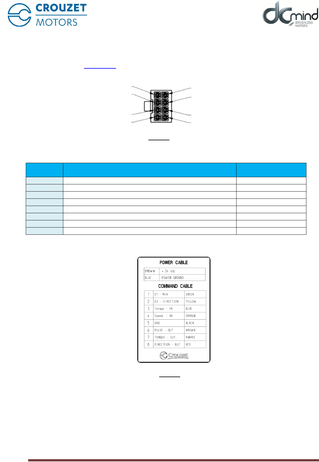
7.3. Control logic bundle
Comprises a UL-approved cable, style 2464 80°C 300V, 500mm long as standard, fitted with a Molex
connector reference 43025-0800 8 contacts:
Pin
Function
Colour of wires
(AWG24)
1
Input no.1 – On / Off
Vert / Green
2
Input no. 2 – Direction of rotation
Jaune / Yellow
3
Input no. 3 – Torque set-point 0-10V or PWM
Bleu / Blue
4
Input no. 4 – Speed set-point 0-10V or PWM
Orange / Orange
5
Logical earth - 0V DC
Noir / Black
6
Output no. 1 – Encoder 12 or 24 pts per rev
Marron / Brown
7
Output no. 2 – Torque limit reached
Violet / Purple
8
Output no. 3 – Actual direction of rotation
Rouge / Red
a label attached to the motor provides this information:
References for the connector to be used:
On the board: Molex series 43045
On the cable: Molex series 43020
If the cable is more than 3m long, tests should be conducted in situ.
Figure 5
Figure 6
8
6
4
2
7
5
3
1

TNi21
07 April 2016 Page
26/38
7.4. Power supply cable
Function
Colour of wires
(AWG16)
Power supplied: +12V DC → +32V DC
Marron / Brown
Power earth: 0V DC
Bleu / Blue
The power supply cable is UL-approved style 2517 105°C 300V, 500mm long as standard.
Where a cable extension is used, the cross-section of the cable used must be of sufficient size for the
current consumed and the length of cable.
TNi21
07 April 2016 Page
27/38
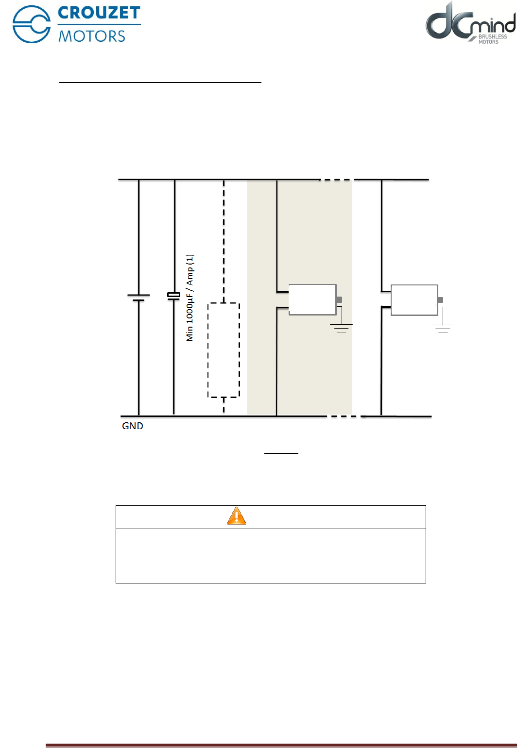
8. MOTOR ELECTRICAL CONNECTION
8.1. Power connection
We recommend that the motor frame is earthed.
Diagram showing power connections.
Figure 7
(1) Fit capacitors to smooth out inrush current. Recommended value 1000µF per Amp consumed.
(2) Optional. The ballast circuit eliminates over-voltages produced during braking. See next section.
CAUTION
REVERSED POLARITY
The product is not protected against reversed polarity in the power
cable.
Reversing the polarity could damage the product beyond repair.
8.1.1. Ballast circuit
When the motor brakes, the kinetic energy stored in the inertia in rotation is returned to the power supply and
generates an over-voltage. This over-voltage can be damaging to the motor or other devices connected to
the same power supply.
Where there is frequent braking, an external ballast circuit should be used.
In all cases, it is necessary to carry out sizing tests.
Note: upon request, the motor can be supplied with much weaker, non-regenerative braking. In that case, no
ballast circuit is required.
Rated voltage
Power Supply
Ballast circuit (2)
DCmind
Motor
DCmind
Motor (n)
TNi21
07 April 2016 Page
28/38
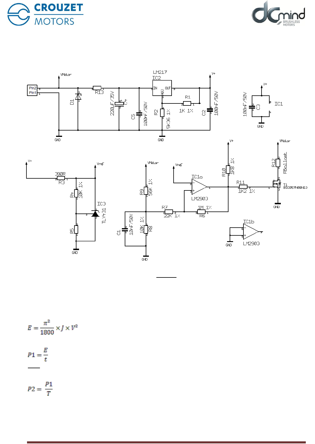
8.1.1.1. Proposed ballast circuit diagram.
The arrangement below dissipates braking energy into a resistor, thus limiting the over-voltage at the motor
terminals.
Figure 8
8.1.1.2. Sizing resistor R12 (RBallast)
The lower the resistor value, the higher the braking current. Typical values are in the region of several Ohms.
Where V is the speed of rotation in rpm and J the inertia in kg.m². The energy E in Joules stored in the
inertia is given by:
If t is the braking time in seconds, the power P1 dissipated during that time will be:
Note: Time t is adjusted via the value of the deceleration ramps in the MMI.
If T is the time interval between two braking instances in seconds, the average power dissipated, P2, will be:
The resistor must be sized to dissipate power P2 while accepting the peaks at P1.
It should be noted, however, that this calculation is simplified and pessimistic, since it does not take into
consideration the energy stored in the capacitors nor that lost in friction, the gearbox, etc.
TNi21
07 April 2016 Page
29/38
8.1.1.3. Selecting the cut-off voltage
The cut-off voltage should be selected:
- According to the power supply
- According to other devices connected to the same power supply.
If your power supply does not tolerate current feedback, fit a diode in series upstream of the ballast circuit to
protect it.
A typical cut-off voltage would be between +10% and +20% of the supply voltage.
Example: For 24V DC the cut-off voltage would be 28V DC
List of components for typical operating voltages:
Rated voltage
12V
24V
32V
Cut-off voltage
14V
28V
36V
D1
SMBJ14A
SMBJ28A
SMBJ36A
R13
0R
560R 0.5W
1K 1W
R5
15K 1%
4K32 1%
3K09 1%
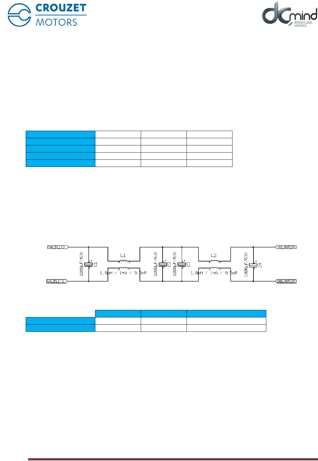
8.1.2. Protection for EMC
To ensure that the product is compatible with EMC standards IEC 61000-6-1, IEC 61000-6-2,
IEC 61000-6-3 and IEC 61000-6-4.
We recommend:
- Earthing the motor with the shortest possible length of earth braid.
- For conducted emissions with an unstabilised power supply, add a capacitor based filter and
common mode choke to the main power supply (see filter structure example below):
Component list for the above filter:
Reference
Manufacturer
Characteristics
C1 to C4
/
/
1000µF / 63V / polarised
L1 and L2
744 826 141 8
WE
1.8mH / 14A / 9.5mΩ
TNi21
07 April 2016 Page
30/38
8.2. Protective devices
DANGER
PROTECTIVE DEVICES
The product includes internal protection devices which cut the power
supply to the motor, when activated. Since the motor is no longer
being controlled, driving forces may drop.
• The manufacturer of the system is responsible for complying with all
the safety rules applicable in the event of product failure.
Failure to take these precautions could result in death or serious
injury.
CAUTION
OVER-VOLTAGES
Exceeding the maximum recommended power supply threshold will
result in the product being destroyed.
• Check the motor's supply voltage before connecting it.
If these precautions are not taken, the result could be injury or
damage to equipment.
8.2.1. Voltage protection
The product has protection against over and under-voltages.
Protection against over-voltages:
The over-voltage threshold is set to 56V(*).
When the power supply voltage exceeds the threshold, the product automatically goes into SAFE mode:
power to the motor is then cut and it is no longer controlled.
To reset the motor, it is necessary:
- That the supply voltage is lower than 56V(*)
- The motor inputs are in OFF mode.
Protection against under-voltages:
When the power supply voltage drops below 9V, the product automatically switches to SAFE mode: power to
the motor is then cut and it is no longer controlled.
To reset the motor, it is necessary:
- That the supply voltage is greater than 10V
- The motor's On / Off input is in OFF mode.
(*) 36V prior to 15 October 2015
8.2.2. Temperature protection
The product includes temperature protection via a temperature sensor on the motor control board.
Temperature protection:
When the internal temperature exceeds 110°C, the product automatically switches to SAFE mode: power to
the motor is then cut and it is no longer controlled.
To reset the motor, it is necessary that:
- The temperature is below 90°.
- The motor's On / Off input is in OFF mode.
TNi21
07 April 2016 Page
31/38
8.2.3. Current limiting
The product has an internal current limiter. This limiter operates directly on the motor through hardware. The
limiter automatically clips the current to the peak current value in the motor phases.
If the limit is reached, the motor's performance is reduced.
This product is not designed to operate continuously at this limit (see the "Electrical data" section).
8.3. Connecting inputs/outputs
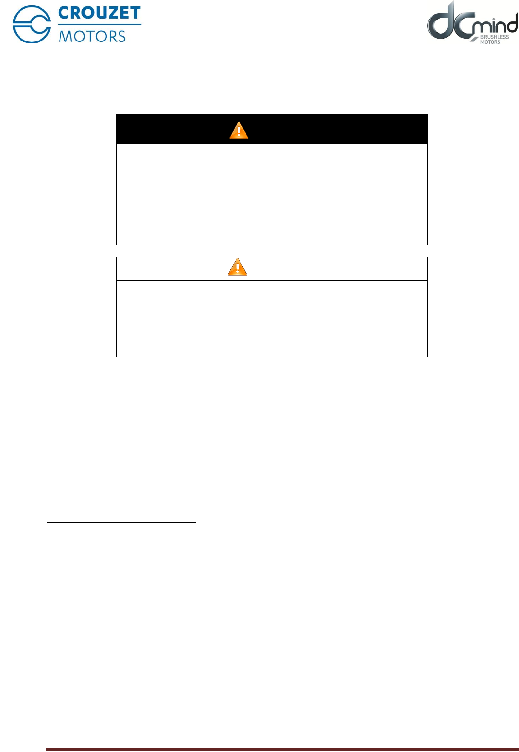
8.3.1. Equivalent inputs diagram
NPN digital inputs: "ON/OFF" and "Direction of rotation"
Figure 9
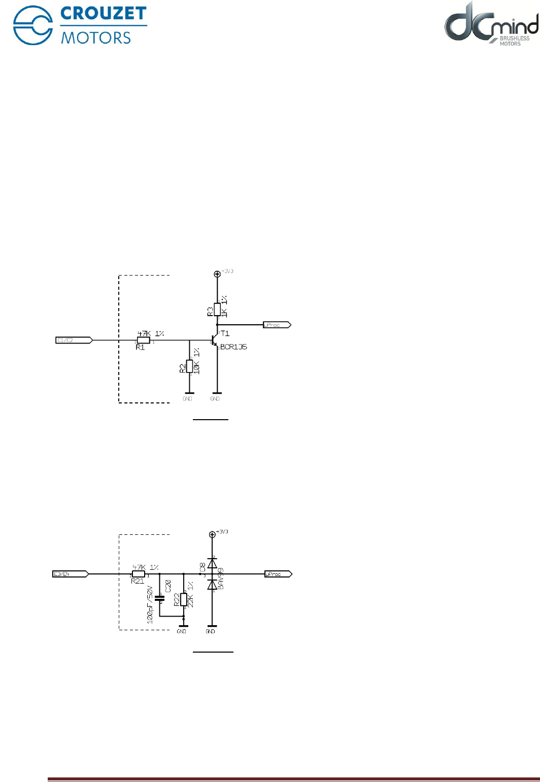
Analogue inputs / PWM: "Speed set-point" and "Torque set-point"
Figure 10
TNi21
07 April 2016 Page
32/38
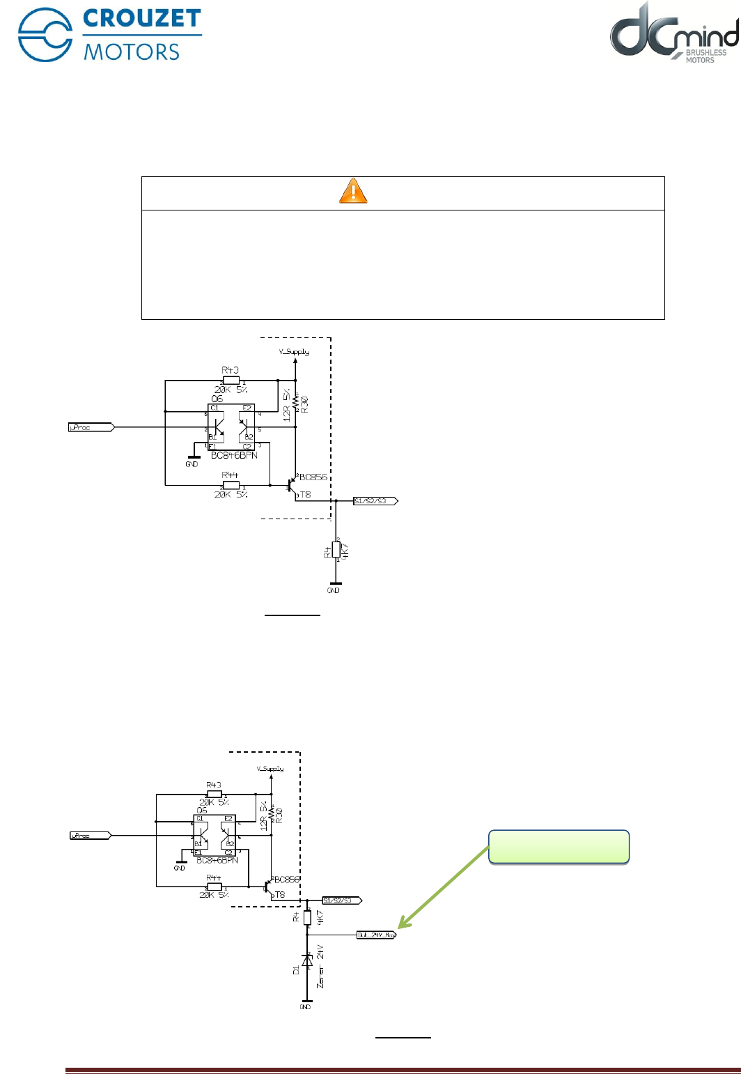
8.3.2. Equivalent outputs diagram
PNP outputs to 50mA max. open slip-ring
Fit a pull-down resistor (recommended value 4.7 kΩ).
CAUTION
EARTHING THE OUTPUTS
The accidental earthing of the outputs or connecting them to a capacitive load will
result in them being destroyed.
Before powering up the motor, check that the outputs are wired correctly.
If these precautions are not taken, the result could be injury or damage to
equipment.
Figure 11
Caution: the output level is equal to the motor's supply voltage:
if V DC = 32V then S1 / S2 / S3 = 32V.
If there is rejection, the voltage increases as a result; it may rise to the maximum of 56V (over-voltage
threshold value).
If, for your application, it is necessary to limit the voltage at these outputs, you should make the following
arrangement.
Figure 12
Client output (24V)

TNi21
07 April 2016 Page
33/38
9. OPERATING MODE
9.1. Preliminaries
DCmind motors with TNI21 integrated electronics are designed to operate by regulating the speed with an
adjustable torque limiter.
These electronics operate in trapezoidal switching mode.
There are two types of board available in the catalogue:
- Version with proportional 0-10V inputs
- Version with proportional PWM inputs
The speed is controlled by a factory-set PID to allow a wider operating range. The torque supplied by the
motor is automatically limited internally.
9.2. Functions associated with inputs
9.2.1. Function E1 - On / Off
State
Function
0
De-activates the power
1
Activates the power
State 0 corresponds to the motor's OFF mode.
State 1 corresponds to the motor's ON mode.
Changing to 1 activates the power: speed regulation (as per the set-point applied to E3, in 0-10V or PWM)
with torque limiting (as per the set-point applied to E4, in 0-10V or WM).
Changing to 0 cuts the power, following the speed profile (deceleration ramp).
9.2.2. Function E2 - Direction of rotation
State
Function
0
Anti-clockwise rotation (SI)
1
Clockwise rotation (SA)
If the motor is rotating, the direction is reversed:
- Instantly if the speed is less than 1000 rpm
- Via a controlled slow-down phase until the speed reaches 1000 rpm.
9.2.3. Function E3 - Speed set-point
The speed set-point proportional input operates in the range 70 to 4000 rpm.
Starting hysteresis set to 70 rpm.
Stopping hysteresis set to 35 rpm.
Below these values, the speed set-point is considered as zero.
This input operates either on 0-10V or PWM, depending on the product ordered.

TNi21
07 April 2016 Page
34/38
9.2.4. Function E4 - Torque limiter set-point
The torque limiter proportional input is linear throughout its range.
The corresponding scale varies according to the type of motor:
Drive basis
Min terminal (0V or 0%)
Max terminal (10V or 100%)
80140_TNI21
360 mN.m
35 mN.m
80180_TNI21
700 mN.m
35 mN.m
80280_TNI21
1000 mN.m
100 mN.m
This input operates either on 0-10V or PWM, depending on the product ordered.
9.3. Functions associated with outputs
All outputs are open slip-ring PNP.
The voltage delivered by these outputs is V DC (power supply voltage)
9.3.1. Function S1 - Encoder output
A fixed width top hall (500µs) is generated each time that one of the motor's three hall sensors changes
state.
Motors 80140_TNI21 and 80180_TNI21 have twelve top halls per motor revolution (two pairs of poles).
Motor 80280_TNI21 has 24 top halls per motor revolution (four pairs of poles).
The rest state of output S1 is 0. The calibrated pulse is positive (set to V DC)
9.3.2. Function S2 - Torque limiter output
Output S2 gives information on the motor's torque limiter:
If S2 = 0V (output at low state) → Normal operation
If S2 = VCC (output at high state) → Torque limit reached
9.3.3. Function S3 - Actual direction of rotation output
Output S3 gives the actual direction of rotation of the motor shaft:
If S3 = 0V (output at low state) → Rotation in reverse direction (SI)
If S3 = VDC (output at high state) → Rotation in forward direction (SA)

TNi21
07 April 2016 Page
35/38
9.4. SAFE mode
Motors with TNI21 integrated electronics have a SAFE mode.
If power to the motor is cut, no holding torque is applied (free shaft)
SAFETY
Range limit
Action
Excessive temperature
110°C Stop
90°C OK to run
Re-start necessary
Under-voltage
9V Stop
10V OK to run
Re-start necessary
Over-voltage
36V Stop
35V OK to run
Re-start necessary
Motor re-start procedure following the detection of an error:
- To resolve the cause of a fault.
- Move to off mode: deactivate "On / Off" digital input no. 1
- Return to on mode: activate "On / Off" digital input no. 1
10. DIAGNOSTICS AND TROUBLESHOOTING
10.1. Mechanical faults
Error
Cause
Resolving the fault
Excessive heating
Overload
Holding brake not released
Reduce the load
Check the holding brake control
Whistling or knocking
Defective bearings
Contact after-sales
Friction noises
A rotating transmission component is
rubbing
Align the transmission component
Radial vibration
Transmission component not sufficiently
accurately aligned
Transmission component out of balance
Twisted shaft
Resonance in the mounting
Align the transmission component
Balance the transmission
component
Contact after-sales
Check the rigidity of the motor
mounting
Axial vibration
Transmission part not sufficiently
accurately aligned
Impact on the transmission component
Resonance in the mounting
Align the transmission component
Check the transmission component
Check the rigidity of the motor
mounting
10.2. Electrical problems
Error
Cause
Resolving the fault
The motor does not start or is
difficult to start
Overload
Fault in connection wires
Inadequate power supply
Reduce the load
Check the connecting wires
Check the power supply
Contact after-sales
Significant heating of the
stator
Overload
Reduce the load
Heating at the connection
terminals
Loose or poorly tightened power supply
wires
Re-tighten the screws
TNi21
07 April 2016 Page
36/38
11. SERVICE, MAINTENANCE AND PROBLEM SOLVING
11.1. Addresses of after-sales service points
Contact your distributor
The list of distributors can be accessed via the Crouzet Automatismes web site www.crouzet.com
11.2. Storage
Motors should only be transported and stored in a dry environment, free from dust and protected from
vibration.
The ambient conditions are stated in the product's data sheet and should be complied with.
Storage time is essentially dictated by the stability of the lubricants and should be less than 36 months.
To maintain it in operating condition, occasional running of the drive solution is recommended.
11.3. Maintenance
Only the manufacturer is authorised to carry out repairs. Any work done by unauthorised persons will nullify
the manufacturer's warranty and liability.
Repairing the motor when fitted is not possible.
Before doing any work on the drive system, please consult the Installation and Switching on section,
to find out what measures to take.
We recommend that the following is done at regular intervals with the power switched off.
Connections and mounting
=> Check all cables and connections regularly for signs of damage. Replace any damaged cables
immediately.
=> Check that all transmission components are properly secure.
=> Re-tighten all mechanical and electrical bolted assemblies to the appropriate torque.
WARNING
UNEXPECTED MOVEMENT
In the event that the permitted ambient conditions are not maintained,
foreign bodies from the surrounding area may enter and cause
unexpected movement or damage to equipment.
• Check the ambient conditions.
• Fluids should not be allowed to stagnate in the shaft bushing.
If these precautions are not taken, the result could be death,
serious injury or damage to equipment.
Cleaning
Remove dust and dirt from the motor regularly. Insufficient dissipation of heat into the atmosphere may
cause abnormally high temperatures.
Motors are not designed to be cleaned with a high pressure cleaner. A high pressure could cause water to
enter the motor's interior.
If cleaning products or solvents are used, care should be taken not to damage the motor's power supply
wires and any options (brake), ball bearings or the finish on the motor.
Check / bed in the holding brake
Occasional braking with a moved load will help to maintain the holding brake's holding torque. If the holding
brake is not called upon to do any mechanical work for a long period (braking with a moved load), some of its
parts could corrode or deposits might accumulate and so reduce its holding power.

TNi21
07 April 2016 Page
37/38
The holding brake is bedded in before it leaves the factory. If the holding brake is not called upon to do any
mechanical work for a long period, some of its parts could corrode. If the holding brake does not provide the
holding torque specified in its technical characteristics, it might be necessary to bed it in again.
=> Dismount the motor. Close the holding brake.
=> Measure the torque from the holding brake, using a dynamometer.
=> Compare the reading with the holding torque stated in the data sheet.
=> If the holding torque differs appreciably from the values stated, turn the motor shaft by hand 25
revolutions in both directions.
=> Repeat the operation. If, after three repetitions, the holding torque is not re-established, please contact
your dealer.
11.4. Replacing the motor
=> Disconnect all sources of power. Ensure that no power is still being applied (safety instructions).
=> Identify all connections and dismount the product.
=> Replace it with a motor with the same reference.
=> Install the new product in accordance with chapter 4 "Installation".
=> Carry out commissioning in accordance with chapter 5 "Commissioning".
11.5. Shipping, storage, disposal
Comply with the ambient conditions stated in the "TECHNICAL CHARACTERISTICS" chapter.
Shipping
Always protect the product against impacts when shipping it.
For this, use the original packing.
Storage
Only store the product under the permissible ambient temperature and humidity conditions specified.
Protect the product from dust and dirt.
Disposal
The product comprises various materials the can be re-used or which are subject to selective recycling.
Dispose of any product in accordance with local requirements.

TNi21
07 April 2016 Page
38/38
11.6. Terms and abbreviations
Level of protection
The level of protection is a standardised rating used for electrical equipment ans intended to describe the
protection against the ingress of solids and liquids into the motor enclosure, e.g. IP54M. The M indicates that
testing was done with the motor running.
The value does not take into consideration sealing around the output shaft, which must be taken into
consideration by the installer.
Axial forces
Tension or compression forces acting on the shaft in a longitudinal direction.
Radial forces
Forces acting on the shaft in a radial direction.
Direction of rotation
Positive or negative direction of rotation of the motor shaft. A positive direction of rotation is clockwise
rotation of the shaft when looking at the motor from the output shaft side.
Rated speed
Speed of rotation of the motor when the nominal torque is applied.
Rated current
Current drawn by the motor when the nominal torque is applied.
Nominal torque
The maximum applicable torque on the motor shaft during continuous operation.
Abbreviations in common use:
TNI21: Commercial name for the new range of electronics for the CROUZET DCmind brushless
range.
TOR (switching): Type of digital input / output (On / off)
PWM: Pulse Width Modulation
SA: Clockwise
SI: Anti-clockwise
EMC: Electromagnetic compatibility
