RU2R1
Ru2R1 RU2R1 RU2R1 datasheet library assets cdn.crouzet-control.com
2016-08-24
: Crouzet Ru2R1 RU2R1 en datasheet library assets
Open the PDF directly: View PDF ![]() .
.
Page Count: 3
› RU2R1
› Timers
› DIN rail mount
› 22.5 mm - 2 Relays 8A
›Relay output
›Multi-function or mono-function
›Multi-range
›Multi-voltage
›Screw terminals
›LED status indicator
Specications
Functions Timing Output Nominal rating Connections Supply voltage Code
A - Ac - At - B - Bw
- C - D - Di - H - Ht
0,1 s →100 h 2 changeover
relay
2 x 8 A Screw terminals 24 V DC / 24
→240 V AC
88866305
Timing
Timing ranges (7 ranges) 1 s - 10 s - 1 min - 10 min - 1 h - 10 h - 100 h
Repetition accuracy with constant parameters ± 0.5 % (IEC/EN 61812-1)
Drift Temperature ± 0,05 % / °C
Drift Voltage ± 0,2 % / V
Display accuracy according to IEC/EN 61812-1 ± 10 % / 25 °C
Immunity from micro power cuts : typical < 10 ms
Minimum pulse duration typically 30 ms
Minimum pulse duration typically (under load) 100 ms
Maximum reset time by de-energisation typically 120 ms
Supply
Multi-voltage power supply Depending on version
Frequency (Hz) 50 / 60
Operating factor 100 %
Operating range 85 →110 % Un
Max. absorbed power
15 VA (400 VAC)
50 VA (240 VAC)
0,7 W (24 VDC)
1,2 VA (12 VAC)
0,5 W (12 VDC)
Output specication
Rated power 2000 VA/80 W
Maximum breaking current 8 AAC 250 VAC resistive
8 ADC 30 VDC resistive
Minimum breaking current 10 mA / 5 VDC

I Timers I 02 I www.crouzet-control.com
Output specication
Voltage breaking capacity 250 VAC / 8 AAC resistive
250 VDC / 0,3 A resistive
Electrical life (operations) 10⁵
8 A 250 VAC resistive
Mechanical life (operations) 10 x 10⁶
Breakdown voltage acc. to IEC/EN 61812-1 2,5 kV / 1 min / 1 mA / 50 Hz
Impulse voltage acc. to IEC/EN 60664-1, IEC/EN 61812-1 5 kV
wave 1.2 / 50 μs
2 changeover relays, AgNi (cadmium-free) 2 C/O
RQR1- RQR6 2 open contacts
General characteristics
Conformity to standards IEC/EN 61812-1
IEC/EN 61000-6-1
IEC/EN 61000-6-2
IEC/EN 61000-6-3
IEC/EN 61000-6-4
Certications CE, UL, cUL, CSA, GL
Temperature limits use (°C) -20 →+60
Temperature limits stored (°C) -30 →+60
Installation category (acc. to IEC/EN 60664-1) Voltage surge category III
Creepage distance and clearance acc. to IEC/EN 60664-1 4 kV / 3 mm
Protection (IEC/EN 60529) IP20
IP40
Degree of protection acc. to IEC/EN 60529 Front face IP50
Vibration resistance acc. to IEC/EN 60068-2-6 20 m/s² 10 Hz →150 Hz
Relative humidity no condensation acc. to IEC/EN 60068-2-30 93 % non-condensing
Electromagnetic compatibility - Immunity to electrostatic discharges
acc to IEC/EN 61000-4-2
Level III (Air 8 kV / Contact 6 kV)
Immunity to radiated, radio-frequency, electromagnetic eld acc.
IEC/EN 61000-4-3
Level I (1 V/m : 2,0 G Hz →2,7 G Hz)
Level II (3 V/m : 1,4 G Hz →2,0 G Hz)
Level III (10 V/m : 80 M Hz →1 G Hz)
Immunity to rapid transient bursts acc. to IEC/EN 61000-4-4 Level III (direct 2 kV / Capacitive coupling clamp 1 kV)
Immunity to shock waves on power supply acc. to IEC/EN 61000-4-5 Level III (2 kV / common mode 2 kV/residual current mode 1 kV)
Immunity to radio frequency in common mode acc. to
IEC/EN 61000-4-6
Level III (10V rms : 0.15 M Hz to 80 M Hz)
Immunity to voltage dips and breaks acc. to IEC/EN 61000-4-11 0 % residual voltage, 1 cycle
70 % residual voltage, 25/30 cycles
Mains-borne and radiated emissions acc. to EN 55022 (CISPR22),
EN55011 (CISPR11)
Class B
Fixing : Symmetrical DIN rail 35 mm
Terminal capacity Single-wire without ferrule 1 x 0,5 →3,3 mm² (AWG 20 →AWG 12)
2 x 0,5 →2,5 mm² (AWG 20 →AWG 14)
Terminal capacity Multi-wire with ferrule 1 x 0,5 →2,5 mm² (AWG 20 →AWG 14)
2 x 0,5 →1,5 mm² (AWG 20 →AWG 16)
Housing material Self-extinguishing
Shock test IEC/EN 60068-2-27 15 g - 11 ms
Short interruption on power line acc to IEC/EN 61000-4-11 0 % residual voltage, 250/300 cycles
Weight : casing 22,5 mm 88 866 175 (RQR1) : 81 g
88 866 176 (RQR6) : 81 g
88 866 215 (RA2R1) : 87 g
88 866 300 (RU2R4) : 86 g
88 866 303 (RU2R3) : 90 g
88 866 305 (RU2R1) : 88 g
88 866 385 (RX2R1) : 88 g
I Timers I 03 I www.crouzet-control.com
General characteristics
Insulation resistance according to IEC/EN 60664-1 > 500 MOhm(s) (500 VDC)
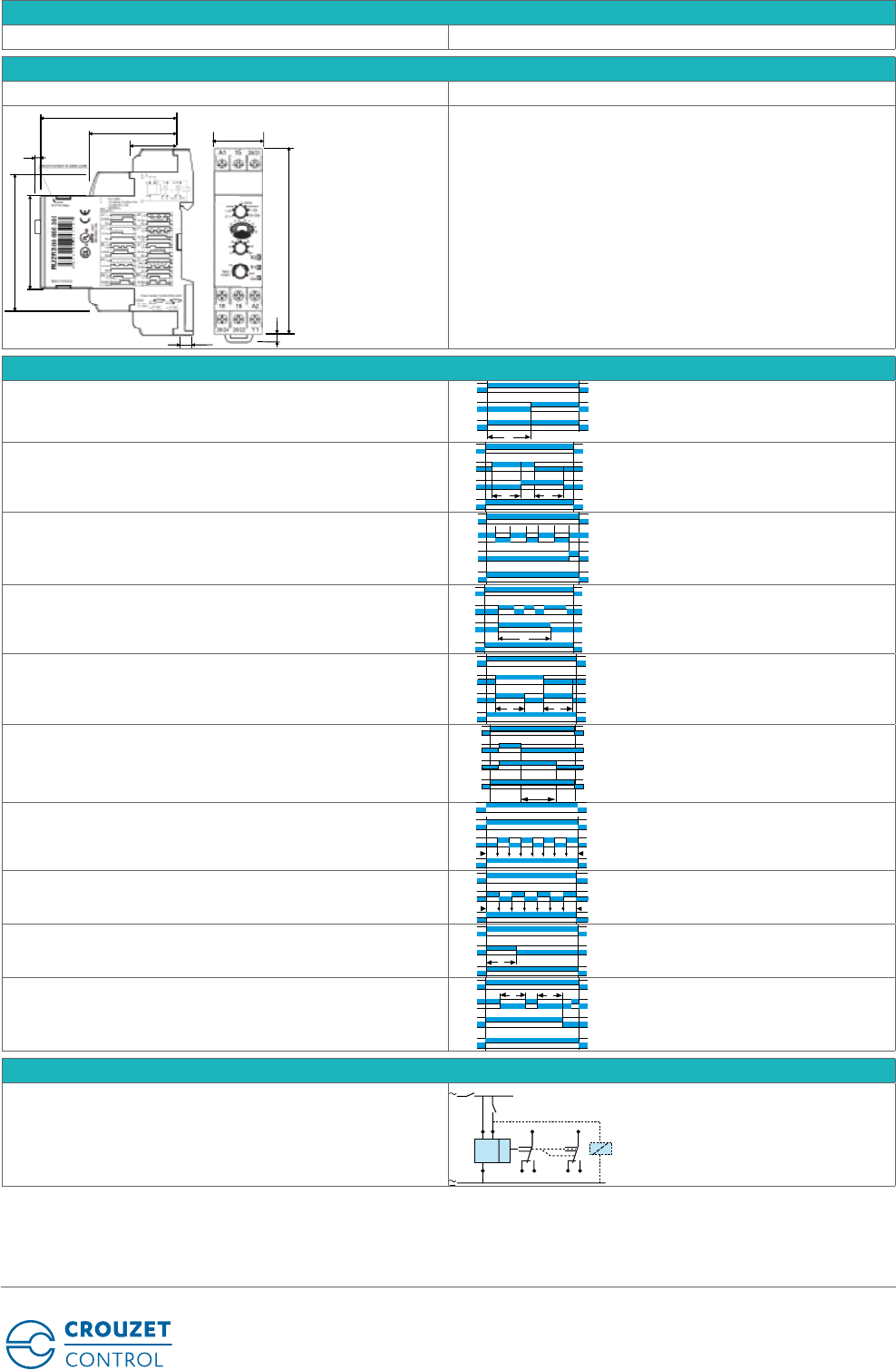
Dimensions
RU2R1
68
5.5
22.5
23.2
44
3.5
45
67.5
90
2.6
Curves
Function A
Delay on energisation
U
R1/R2
R2
T
Function Ac
Timing after closing and opening of control contact
U
Y1
R1/R2
TT
R2
Function At
Timing on energisation with memory
U
Y1
R1/R2
T = t1+t2+t3
t1 t2 t3
R2
Function B
Timing on impulse one shot
U
Y1
R1/R2
T
R2
Function Bw
Pulse output (adjustable)
U
Y1
R1/R
2
R2
TT
Function C
Timing after impulse delay OFF
U
Y1
R1/R2
T
R2
Function D
Flip-op Pause start
U
TTTTTTTT
R1/R2
R2
A1 Y1
Function Di
Flip-op Pulse start
U
R1/R2
TTTTTT T
R2
Function H
Timing on energisation T
R1/R2
U
R2
Function Ht
Delay on energisation with memory
t1
R1/R2
Y1
U
t2
R2
T = t1+t2
Connections
2 changeover relay outputs
U
A1
R1 R2
15
A2
1816
25/21
28/2426/22
Y1
+
