Software Em4 Online Help UK
2016-05-20
: Crouzet Software Em4-Online-Help Uk Software_em4-online-help_UK Softwares crouzet-automation
Open the PDF directly: View PDF ![]() .
.
Page Count: 237 [warning: Documents this large are best viewed by clicking the View PDF Link!]
em4 soft Online Help

em4 soft Online Help
1
1. em4 soft Online Help ............................................................................................................................................... 3
1.1 Overview of the programming workshop ......................................................................................................... 3
1.1.1 Overview of the Programming Workshop .................................................................................................. 3
1.1.2 Creating or Modifying the Configuration of an Application ....................................................................... 5
1.2 How to start with the programming workshop ................................................................................................. 6
1.2.1 Glossary ...................................................................................................................................................... 7
1.2.2 How to create a new program .................................................................................................................... 8
1.2.3 How to Program an Application Using the Programming Software ........................................................... 8
1.2.4 How to connect the programming workshop to the controller ................................................................. 8
1.2.5 How to transfer the program from the PC to the controller ...................................................................... 8
1.2.6 How to protect the controller resident program ....................................................................................... 8
1.2.7 How to Debug an Application Without Loading it onto the Controller: Simulation .................................. 9
1.2.8 How to Monitor and Modify an Application Running on the Controller: Debugging .............................. 12
1.2.9 Meaning of the Error Codes on the Controller Front Panel ..................................................................... 14
1.2.10 How to diagnose the state of the controller .......................................................................................... 14
1.2.11 How to control the controller from the programming workshop .......................................................... 15
1.2.12 How to Control the Controller from the Front Panel ............................................................................. 15
1.2.13 How to Configure an Application from the Controller Front Panel........................................................ 17
1.2.14 How to Dynamically Modify Program Data Using the Controller Front Panel ....................................... 17
1.2.15 How to recover the controller resident program in the programming workshop ................................. 17
1.2.16 How to Check an Application Using the Programming Workshop ......................................................... 17
1.2.17 How to check the controller software .................................................................................................... 19
1.2.18 How to use the backup memory cartridge ............................................................................................. 20
1.2.19 How to Configure the Language of the Programming Workshop and the Controller ........................... 21
1.2.20 How the Controller Behaves in the Event of Power Failure ................................................................... 21
1.2.21 How to Import an Application Developed with Millenium 2 into Millenium 3 ...................................... 22
1.2.22 How to customise the function bar ........................................................................................................ 22
1.3 Functions Accessible from the Front Panel ..................................................................................................... 25
1.3.1 INPUTS-OUTPUTS Screen ......................................................................................................................... 25
1.3.2 PARAMETERS Menu ................................................................................................................................. 26
1.3.3 ON/OFF Menu .......................................................................................................................................... 27
1.3.4 SYSTEM Menu ........................................................................................................................................... 28
1.3.5 ACCESSORY Menu ..................................................................................................................................... 33
1.3.6 COMMUNICATION Menu ......................................................................................................................... 33
1.4 FBD Language .................................................................................................................................................. 35
1.4.1 Overview of FBD language........................................................................................................................ 35
1.4.2 FBD Language Elements ........................................................................................................................... 38
1.4.3 FBD Programming ................................................................................................................................... 175
1.4.4 Example of an FBD Application............................................................................................................... 202

em4 soft Online Help
2
1.5 Controller Connections .................................................................................................................................. 204
1.5.1 Connection with the Programming Workshop ....................................................................................... 205
1.5.2 Communication via the Modbus Interface ............................................................................................. 213
1.5.3 Communication Via Ethernet Extension ................................................................................................. 215
1.5.4 Communication Interface via the 2G Connection .................................................................................. 215
1.6 Functions of the Programming Workshop .................................................................................................... 221
1.6.1 Functions ................................................................................................................................................ 221
1.6.2 Description of Menus ............................................................................................................................. 233
em4 soft Online Help
3
1. em4 soft Online Help
( § 1.1 )
Online Help em4 soft version 1.2
04/2014
1.1 Overview of the programming workshop
( § 1. )
( § 1.1.1 )
At a Glance
Subject of this Chapter
This chapter provides an overview of the programming workshop
What's in this Chapter?
This chapter contains the following topics:
Overview of the Programming Workshop( § 1.1.1 )
Creating or Modifying the Configuration of an Application( § 1.1.2 )
1.1.1 Overview of the Programming Workshop
( § 1.1 )
( § 1.1.2 )
Languages Used
The controller offers 1 programming language:
FBD language: Function Block Diagram
This language use:
Predefined function blocks:
Timers
em4 soft Online Help
4
Counters
Specific functions:
Time management
Character string
Communication, etc.
FBD mode
FBD mode allows graphic programming based on the use of predefined function blocks.
It offers a large range of basic functions: timer, counter, logic, etc.
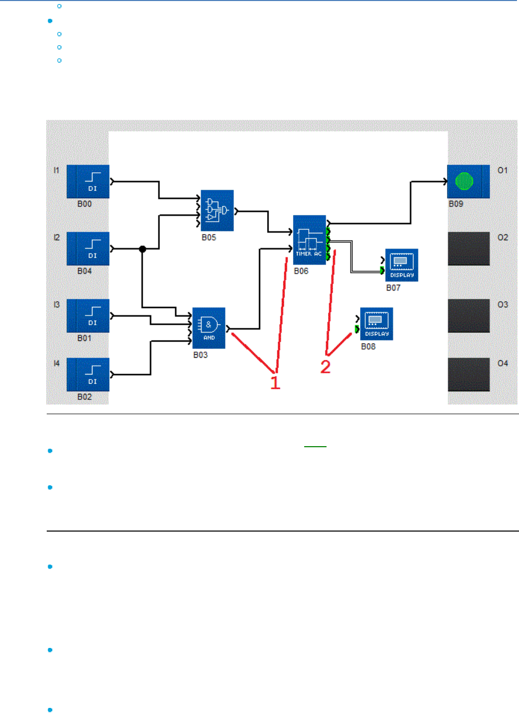
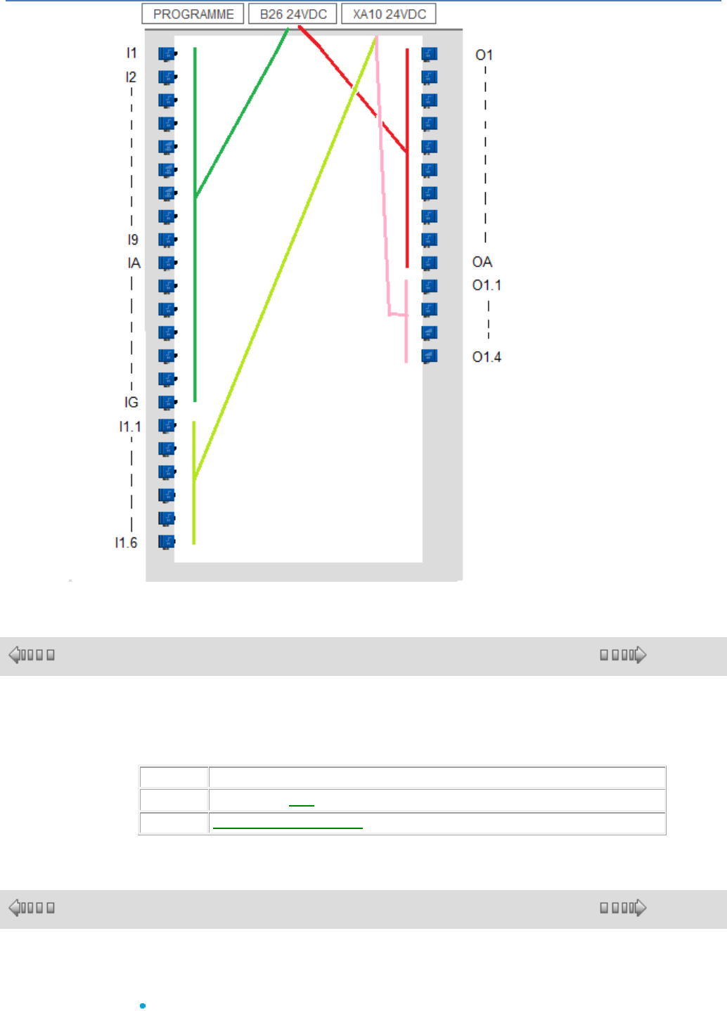
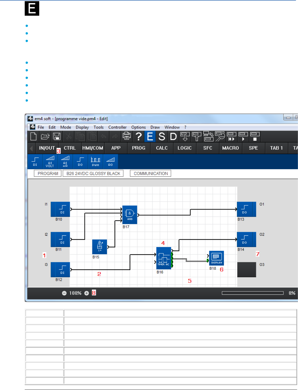
Example of a program in FBD language:
Connection Types
There are several connection types: bit, analog (integer), SFC( § 1.4.2.9.1 ) (Grafcet).
Bit: (see 1 in the above drawing)
Symbolized by a single black line and a black incoming or outgoing arrow. This connection can take
the values 0 or 1.
Analog or integer: (see 2 in the above drawing)
Symbolized by a double black line and a black incoming or outgoing arrow on a green background.
This connection is an integer with a value between -32768 and +32767.
Operating Modes
There are several operating modes for the programming workshop:
Edit mode
Edit mode is used to construct programs in FBD mode, which corresponds to the development of the
application.
In order to simplify the wiring, note that:
- Non-connected enable inputs are by default "enabled", see the Display blocks in the example.
- Non-connected inputs in Logic blocks are not taken into account, see the AND, BOOLEAN blocks in
the example.
Simulation mode
In simulation mode the program is executed offline directly in the programming workshop (simulated
on the PC).
In this mode, each action on the chart (changing the state of an input, output forcing) updates the
simulation windows.
Debugging mode
In Debugging mode, the program is executed on the controller, the programming workshop is
connected to the controller (PC controller connection).
em4 soft Online Help
5
The different windows are updated cyclically.
In simulation and monitoring modes, it is possible to:
View the output states and function block parameters of the program corresponding to the wiring sheet
in the supervision window.
Force the inputs/outputs to test program behavior under specific conditions.
Note: A non-connected BIT input takes the value 0.
A non-connected ANALOG input takes the value 0000.
1.1.2 Creating or Modifying the Configuration of an Application
( § 1.1.1 )
( § 1.2 )
Introduction
This is an important phase, as it determines the future configuration of the work
environment.
Description
The Menu: File / New and the Menu: Controller / Choose the type of controller
are used to choose or modify the type of controller and/or extensions as well as the
programming language.
This function displays a series of screens:
The first is used to choose the type of controller
The second is used to add an extension if necessary
Creating an Application
Procedure for creating an application:
Step
Action
1
Select the menu File / New.
Result: The Choice of Controller window appears.
2
In the Select your controller category zone, select the category by clicking on the
corresponding check box.
The controllers are grouped by categories corresponding to:
The number of inputs/outputs
The presence or absence of an operator display
to finalising the product.
Result: the list of corresponding controllers appears in the Choose the Type of Controller
zone.
3
Select the controller by double-clicking on the corresponding line then confirm using the Next
> button.
Result:
In the Type of Controller window: a summary of the above selection
In the Choose Associated Extensions window
Compatible extensions: listing the extensions compatible with the base selected
above
4
In the Choose Associated Extensions zone, select the extension type to be added in the
Compatible extensions list by double-clicking on the corresponding line or by using the Add
button.
Result: the selected extension appears after the drawing of the base.
The extension can be removed by clicking on it and then using the Delete button.
5
Confirm the configuration by clicking on the Next> button.
6
The edit window appears with a blank wiring sheet.
For each controller type (+ extensions where applicable) there is a drawing background
displayed in the Edit window surrounded by I/O specific to the type chosen as well as a
specific set of FB functions and MACRO presented in the function bar. All functions
incompatible with the selected controller, or all Macros containing a function incompatible with
the selected controller is shown with dark grey shading in the function bar. The names of the
controller and extensions are displayed above the wiring sheet

em4 soft Online Help
6
Modifying the Configuration of an Application
Procedure for modifying the configuration of an application:
Step
Action
1
Click on the menu : Controller / Choose the type of controller...
or click the button of the base or an extension
Result: The Controller Choice window appears on screen.
2
Confirm the changes by clicking on the Next button.
Result: The wiring sheet is displayed on the screen.
1.2 How to start with the programming workshop
( § 1.1.2 )
( § 1.2.1 )
At a Glance
Subject of this Chapter
This chapter explains, through a set of questions and answers, how to use the
programming workshop.
What's in this Chapter?
This chapter contains the following topics:
Glossary( § 1.2.1 )
How to create a new program( § 1.2.2 )
How to Program an Application Using the Programming Software( § 1.2.3 )
How to connect the programming workshop to the controller( § 1.2.4 )
How to transfer the program from the PC to the controller( § 1.2.5 )
How to protect the controller resident program( § 1.2.6 )
How to Debug an Application Without Loading it onto the Controller: Simulation( §
1.2.7 )
How to Monitor and Modify an Application Running on the Controller from the
Programming Workshop: Debugging( § 1.2.8 )
Meaning of the Error Codes on the Controller Front Panel( § 1.2.9 )
How to diagnose the state of the controller( § 1.2.10 )
How to control the controller from the programming workshop( § 1.2.11 )
How to Control the Controller from the Front Panel( § 1.2.12 )
How to Configure an Application from the Controller Front Panel( § 1.2.13 )
How to Dynamically Modify Program Data Using the Controller Front Panel( § 1.2.14
)
How to recover the controller resident program in the programming workshop( §
1.2.15 )
How to Check an Application Using the Programming Workshop( § 1.2.16 )
How to check the controller software( § 1.2.17 )
How to Configure the I/O( § 1.2.18 )
How to Configure the Language of the Programming Workshop and the Controller( §
1.2.19 )
How the Controller Behaves in the Event of Power Failure( § 1.2.20 )
How to Import an Application Developed with Millenium 3 into eM4( § 1.2.21 )
How to customise the function bar( § 1.2.22 )

em4 soft Online Help
7
1.2.1 Glossary
( § 1.2 )
( § 1.2.2 )
Description
Definitions of commonly-used terms are provided to make the help easier to read.
AC: Alternative Current (230AC, 24AC)
MAC address: Media Access Control. Unique (worldwide) hardware address of a
network card or peripheral coded on 6 bytes. It is assigned by the device manufacturer.
LCD display: Screen placed on some controller boxes to enable standalone use of the
controller (control, parameter setting, monitoring, etc.) via the use of keys.
Application: User program
Modular or expandable controller: Controller that can be connected side-by-side with
additional intelligent communication units (Modbus, Ethernet), or I/O units, etc. known
as Extensions.
Debugging : Action used to scan data and parameters modified in the controller from
the workshop, on a PC (online mode) or on the controller LCD display.
FB : Functional Block : function block used with the FBD
FBD: Function Block Diagram : Programming language
Wiring sheet: Work surface of the Edit window: Includes the input and output plots for
an application
Drag/Drop: Operation which consists of left-clicking and moving the mouse while
holding down the left button, then releasing the button at the required position on the
screen.
GRAFCET : The IEC 60848 GRAFCET is used to describe or specify the system
behaviour, from an "external" point of view.
Chart: Drawing of the program in the Edit window (also called diagram)
Workshop HMI: Human Machine Interface of the programming workshop executed on
a PC, tablet, etc.
LD: Ladder Diagram
Controller software : Firmware saved in the controller memory. This firmware ensures
controller operation.
Macro: A MACRO is a group of function blocks. It is characterized by its number, its
name, its links, its internal function blocks and its input/output connections.
Archived Macro: This is a MACRO which is moved using Drag/Drop from the FBD
diagram to the function bar's MACRO tab. It is saved in the ClsM3 workshop context for
editing new FB.
Shortcut menu: Menu that appears by right-clicking the mouse.
Monitoring: Action used to read/write controller data from an application on a PC,
tablet, smartphone, etc.
Function bar tab: Function bar button which displays a series of functions or Macros.
Customizable function bar tab: Function bar button in which the workshop user is
able to use Drag/Drop to gather together all the functions and/or Macros he wants.
These buttons and their content are saved in the Workshop context for editing new
FBD.
Gateway: Device that connects networks of different architectures, working on the
application layer. This term may refer to a router.
Program: See application
Diagram: Program drawing in the program window
SFC: Sequential Function Chart, the SFC language is used to describe (part of) the
"internal" structure of the system firmware. It is adapted to the "GRAFCET" specification
language
Supervision: Term characterizing the HMI Software window displaying the program
data and parameters scanned during a simulation or monitoring phase
DISCR: Discrete (digital input or output)
Connection types:
DISCR (Discrete)
ANA (analog)
em4 soft Online Help
8
Status token (SFC)
1.2.2 How to create a new program
( § 1.2.1 )
( § 1.2.3 )
Description
See Creating an Application( § 1.1.2 ).
See Edit window( § 1.4.1.1 ).
1.2.3 How to Program an Application Using the Programming Software
( § 1.2.2 )
( § 1.2.4 )
Description
FBD Programming from the Programming Software( § 1.4.3 ).
1.2.4 How to connect the programming workshop to the controller
( § 1.2.3 )
( § 1.2.5 )
Description
See Configuring the communication between the programming workshop and the
controller ( § 1.5.1.1 )
See Controller connection( § 1.5 )
1.2.5 How to transfer the program from the PC to the controller
( § 1.2.4 )
( § 1.2.6 )
Description
See Transferring the program from the PC to the controller ( § 1.5.1.2 )
See Controller connection( § 1.5 )
1.2.6 How to protect the controller resident program
( § 1.2.5 )
( § 1.2.7 )
Description
See Protection of the program saved on the controller( § 1.5.1.7 )
See Write option window( § 1.6.1.4 )
em4 soft Online Help
9
1.2.7 How to Debug an Application Without Loading it onto the Controller: Simulation
( § 1.2.6
)
( § 1.2.8 )
Introduction
Before loading a program onto a controller, it is possible to simulate execution using the programming
workshop.
In simulation mode, for each action that the user performs, there is a corresponding simulation, whose
results are displayed in the Front Panel( § 1.2.7 ), Edit( § 1.2.7 ) and Supervision( § 1.2.7 ) windows (not
available in this version).
Access
After creating a diagram in the wiring sheet, click on the icon in the controller bar to access
simulation mode.
Front Panel Window
The Front Panel window is automatically available as soon as Simulation mode is launched. The keys
can be used like real keys. Each click allows use of any function that could be accessed from the front
panel of a real controller. The result of these actions is then displayed in the simulation on the LCD
screen.
In simulation on the "Front Panel" window, click on OK with the mouse + Escape on the keypad and
release simultaneously to replace the display on the DISPLAY screen with the menu display.
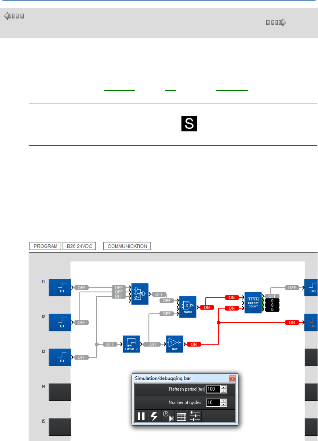
The Edit (Simulation Mode) and Supervision Windows (not available in this version)
The Edit (simulation mode) and Supervision windows (not available in this version) accessible via the
menu : Window are illustrated by an FBD example in the following illustration:
The table below lists the different elements:
em4 soft Online Help
10
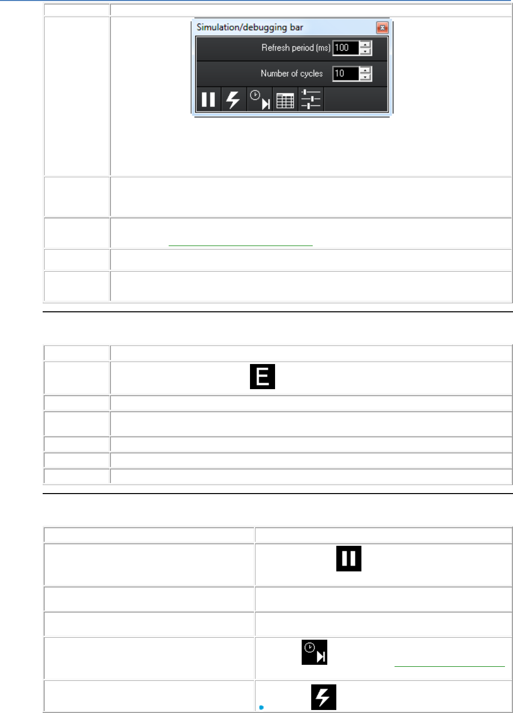
Number
Description
1
Simulation/debugging
The simulation/debugging window is used to modify simulation rates or to simulate certain events affecting the
controller. This highlights all the transient problems, in particular upon launching the application and when power
is restored following a power failure.
The Refresh period corresponds to the frequency with which the output and parameter values are updated in
the open application windows.
The Number of cycles integer is the number of cycles executed during a refresh period.
2
Edit window
The edit window shows the program on a wiring sheet and is used to view the various states and numerical
values being used.
The states and values may be temporarily modified or permanently forced by double-clicking or right-clicking.
3
(not available in
this version)
Supervision window
The supervision window displays inputs and outputs for a selection of functions. The functions are chosen in
Edit mode, see How to Prepare the Supervision Window( § 1.2.7 ).
4
Link in active state
The color is different according to state. Active (ON) or Inactive (OFF) state is specified on each side of the link.
5
(not available in
this version)
The same function block with animated inputs/outputs and parameters in the edit and supervision windows.
How to Prepare the Supervision Window (not available in this version)
To select the functions to be displayed in the supervision window, proceed as follows.
Step
Action
1
Switch to Edit mode by clicking on the button.
2
Open the supervision window from the Window menu.
3
Select: Window / Tile.
Result: The supervision and edit windows appear one below the other.
4
Select a function in the edit window.
5
Drag and drop the function onto the supervision window.
6
Repeat steps 3 to 5 to drop as many functions as necessary.
How to Control Simulation
The table below lists the possible actions on a simulation:
To...
proceed as follows:
Stop or restart simulation...
Use the pause button in the Display/Simulation
Bar/Debugging window or the one in the jump event window.
Highlight all transient problems...
Set the Number of Cycles to 1 and increase the Refresh Period in
the Display/Simulation Bar/Debugging window
Browse the application operation...
Increase the Number of Cycles to 255 in the Display/Simulation
Bar/Debugging window
Go directly to an event or a date and precise time...
Click on the button to go to the Time Prog Jump Event window(
§ 1.2.7 ).
Simulate a power failure followed by a power return...
Click on the button (the simulator clock will freeze).
em4 soft Online Help
11
Click again on the button.
Simulate a power failure followed by a power return at a
particular date and time...
Click on the button (the simulator clock will freeze).
Select: Controller / Read/Write date and time.
Enter the desired date and time for power return in the Date and
Time fields of the Set Clock window.
Confirm by clicking on the Write to the controller button.
Click again on the button.
Display a summary table...
Click on the button to go to the Function Blocks( § 1.2.7 )
window.
How to Modify or Force Analog Inputs...
Click on the button to go to the Modification and Force to
Simulation and Debugging mode( § 1.4.3.3.3 ) page.
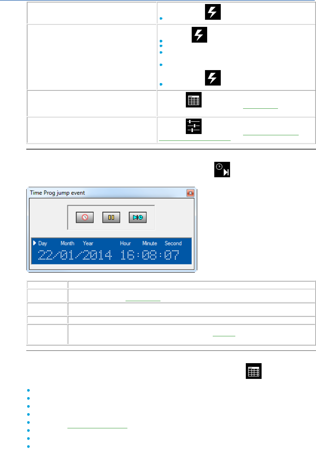
Time Prog Jump Event Window
The Time Prog Jump Event window, accessible using the button in the Display/Simulation
Bar/Debugging window, looks like this:
The table below lists the different elements:
Number
Description
1
The date and time displayed show the simulation time. They depend on the number of cycles executed for each
refresh period and on the basic cycle time( § 1.6.1.1 ).
2
The Set Clock button is used to advance or put back the date and time (confirm by clicking on the Write to the
controller button).
3
The Pause button is used to stop or restart simulation.
4
The Next event button is used to advance to the next Time Prog event.
This button can only be used if events have been defined using a Time Prog function.
Function Blocks Window
The Function Blocks window, accessible using the Summary Table button in the
Display/Simulation Bar/Debugging window, summarizes for each function:
The symbol
The type of function
The block number
The parameters (for the relevant functions)
Whether the Save on power failure( § 1.2.20 ) option has been selected
The current value (for relevant functions)
Whether it is possible to modify function parameters from the controller front panel
The comment entered by the user

em4 soft Online Help
12
It also provides access to the parameters for each function by double-clicking on the relevant line.
1.2.8 How to Monitor and Modify an Application Running on the Controller: Debugging
( § 1.2.7 )
( § 1.2.9 )
Description
To remotely monitor or modify the behavior of a program running on a controller, the user
can use the debugging function. This debugging allows the user:
To temporarily modify or permanently force:
Any of the function outputs
The majority of the function parameters
As well as all the buttons on the controller front panel
Then to display periodically the execution of the program, observing:
The values of the controller I/O and its extensions
The block outputs
The current state of the parameters and the displays of the controller front panel
when online
Switch to Controller and programming workshop debugging Mode
The programmer can only switch to this mode if the controller:
contains a program in which parameter modification is not read/write protected by a
password
contains a program in which parameter modification is read/write protected and where
the programmer knows the password
The HMI checks whether a password protects the program and parameters or the
controller parameters. If this is the case, the HMI displays the Password dialog window.
The chart in the Edit window must be consistent with the program in the controller. The
HMI starts the "Compare the controller data with the program" function. If a difference is
found, the HMI returns to edit mode.
Following these checks, simply click on the button in the toolbar to switch to
debugging mode. After this action, the following is displayed:
Either, in the controller toolbar, a set of icons that can be used to start and stop
application execution in the controller and the frequency at which output and
parameter values are updated in the open application windows.
Or in a "Simulation/Debugging" window
This shows:
The state of the controller I/O and any extensions
The program states
The I/O and parameters (including output parameters) of the FBD function blocks
The current value of each link is displayed near the function block output. Debugging
mode is independent of the "Controller On/Off" function. If the controller is off, only
modifications to the parameters and the inputs on the buttons of the controller front panel
are displayed.
Note: The Debugging mode cannot be considered as a dependable debugging
method, because on the online controller that switches to debugging mode, the basic
cycle time( § 1.6.1.1 ) is extended by the communication times between the PC and
the controller and possible permanent forcing times applied to the application. No
guarantee can be given concerning the actual duration of cycle times during this
operating mode. Moreover, during this operating mode, the WATCHDOG action( §
1.6.1.1 ) linked to the application is deactivated.
In addition, when applications without permanent forcing are executed, the application
may run on the controller for a time that is much shorter than the refresh period of the
PC debugging windows. It is not therefore possible to observe actions on the controller
that are executed at less than twice the debugging screens refresh period (Shannon

em4 soft Online Help
13
sampling rule).
Front Panel Window
This window allows you to click with the mouse on any key on the controller front panel
which is depicted in the window. The keys in the Front Panel window can be used like
keys on the actual controller front panel. Any function which can be accessed from the
front panel of an actual controller can be applied to the actual controller with a single
mouse click. The result of these actions is then displayed in the copy on the LCD screen.
Debugging Control
The commands that can be used to control debugging are:
The Stop button on the controller bar
The On button
The time between 2 displays of controller data on the screen (modifiable value)
The refresh frequency of the Debugging bar corresponds to the frequency at which the
output and parameter values are updated in the application windows that are open
during debugging mode: decreasing this frequency, and consequently the refresh period,
reduces the workload of the programming workshop that monopolizes the PC to the
detriment of other system or user programs.
Note: Modification of the refresh frequency is essential in order to limit the time allotted
to the programming workshop by the Windows system. This is because in older
Windows systems or small PC configurations, the load used by the programming
workshop in debugging mode significantly slows down open applications running in
parallel or system operations.
The Edit Window
Display
Displays user programs written in chart form.
Shows the FBD discrete links in "inactive" color.
Shows the FBD discrete links in "active" color.
Shows each active step of an SFC chart in "active" color.
Shows the current value of each numerical link on an FBD chart.
Animates all FBD functions that have only one discrete output, according to the state
of this discrete output.
Shows the value of all the FBD function parameters, by double-clicking on the function
block.
Forced values are highlighted in the Edit and Supervision windows by a change in
background color.
FBD Actions
Can be used to temporarily modify the state of any Discrete or Token output or link of
an FBD chart, by left-clicking on it with the mouse (change from ON/OFF).
Can be used to temporarily modify the state of any FBD chart output or numerical link,
by left-clicking on it with the mouse, entering a signed integer value in the "Analog
Value" window, and then confirming by pressing OK.
Can be used to permanently force the state of any Discrete or Token link or output of
an FBD chart, by right-clicking on it with the mouse, selecting "Force and maintain" in
the menu displayed, entering ON or OFF in the "Permanent Forcing" window, and
then confirming by pressing OK.
Can be used to permanently force the state of any numerical link output of an FBD
chart, by right-clicking on it with the mouse, selecting "Force and maintain" in the
menu displayed, entering a signed integer value in the "Analog Value" window, and
then confirming by pressing OK.
Can be used to modify the value of a subset of FBD function parameters, by double-
clicking on the function block, modifying one or more of the non-grayed out
parameters and confirming by pressing OK.,
Can be used to release a forced output or link by right-clicking on it with the mouse
and selecting "Release" in the menu displayed.
Can be used to release all forced outputs or links by right-clicking in the window with

em4 soft Online Help
14
the mouse and selecting "Release all" in the menu displayed.
Supervision Window (not available in this version)
Display
Displays the FBD edit functions selected in this window as FBD function blocks.
Shows the discrete FBD function block outputs that are OFF in "inactive" color (blue by
default).
Shows the discrete FBD function blocks that are ON in "active" color (red or pink by
default) (discrete outputs and FBD blocks that are active and not supplied with power
are displayed in orange).
Shows each active step of an SFC chart in "active" color (red by default).
Shows the current value of each numerical output of an FBD function block.
Animates all FBD function blocks that have only one discrete output, according to the
state of its discrete output.
Shows the value of all the FBD function block parameters, by double-clicking on the
function block or right-clicking on each contact or coil with the mouse, and then
selecting "Settings window" in the menu that is displayed.
Forced values are highlighted in the Edit and Supervision windows by a change in
background color.
Actions
Can be used to temporarily modify the state of any Discrete or Token output of an
FBD function block, by left-clicking on it with the mouse (change from ON/OFF)
Can be used to temporarily modify the state of any FBD function block output or
numerical link, by left-clicking on it with the mouse, entering a signed integer value in
the "Analog Value" window, and then confirming by pressing OK.
Can be used to permanently force the state of any Discrete or Token output of an FBD
function block, by right-clicking on it with the mouse, selecting "Force and maintain" in
the menu displayed, entering ON or OFF in the "Permanent Forcing" window, and
then confirming by pressing OK.
Can be used to permanently force the state of any numerical output of an FBD
function block, by right-clicking on it with the mouse, selecting "Force and maintain" in
the menu displayed, entering a signed integer value in the "Analog Value" window,
and then confirming by pressing OK.
Can be used to modify the value of a subset of FBD function block parameters, by
double-clicking on the function block, modifying one or more non-grayed out
parameters, then confirming by pressing OK. This action can also be performed by
right-clicking each contact or coil with the mouse, then selecting "Settings window" in
the menu displayed, modifying one or more non-grayed out parameters, then
confirming by pressing OK.
Can be used to release a forced output by right-clicking on it with the mouse and
selecting "Release" in the menu displayed.
Can be used to release all forced outputs by right-clicking in the window with the
mouse and selecting "Release all" in the menu displayed.
1.2.9 Meaning of the Error Codes on the Controller Front Panel
( § 1.2.8 )
( § 1.2.10 )
Description
See Description of Errors( § 1.6.1.12 )
See Fault menu( § 1.3.4.2 )
1.2.10 How to diagnose the state of the controller
( § 1.2.9 )
( § 1.2.11 )
em4 soft Online Help
15
Description
See Controller diagnostics( § 1.5.1.6 )
See Version menu( § 1.3.4.3 )
1.2.11 How to control the controller from the programming workshop
( § 1.2.10 )
( § 1.2.12 )
Description
See ON/OFF program execution commands( § 1.5.1.4 ).
See Debugging Mode
1.2.12 How to Control the Controller from the Front Panel
( § 1.2.11 )
( § 1.2.13 )
Description
The LCD display and the command keys can be used to:
Identify the controller and its extensions
Monitor the state of the controller
Configure the controller and its extensions (date, time, etc.)
Configure and execute a user program
Transfer user programs to and from a memory cartridge
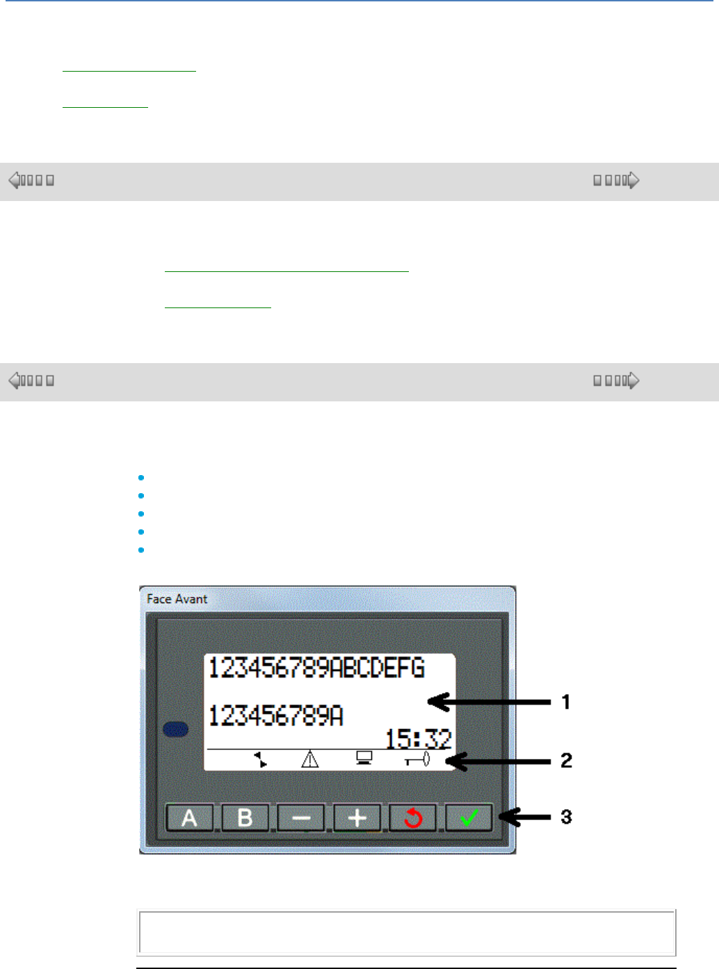
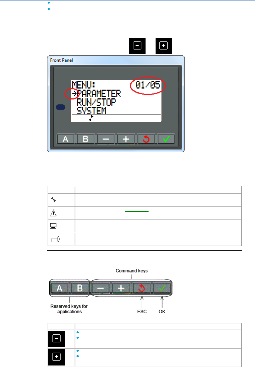
The front panel looks like this:
1
First 4 lines on the screen where the menus and elements associated with each menu are displayed.
2
Illustrative symbols (in the above example all 4 symbols are present)
3
Command keys
Note: By default the LCD screen is on
The LCD screen is switched on and off using the "Light" FB, should it be OFF.
First 4 Lines
On the first 4 lines of the screen, the display consists of:
em4 soft Online Help
16
Either information
Or several actions that can be selected. In this case, only the field that flashes can
be selected and its selection triggers an action
An arrow indicates the selected menu.
Should the information and actions to be performed not fit in the 4 lines, the line number
and total number of lines are displayed in the top right-hand corner.
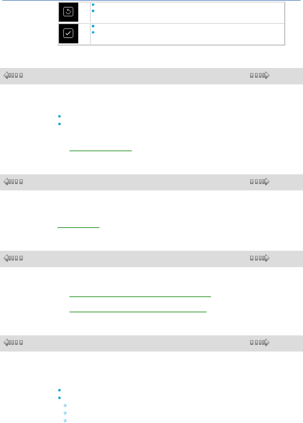
These lines can be accessed via the and keys.
.
On the product, pressing the OK (green) and ESC (red) keys simultaneously replaces
the display on the DISPLAY screen with the menu display.
Symbols
The symbols are described in the table below:
Symbol
Meaning
State of the controller. In ON mode it is moving, in OFF mode it is stationary.
Faults have appeared (see FAULT menu( § 1.3.4.2 )).
The controller is connected to the programming workshop.
The application is protected by a password.
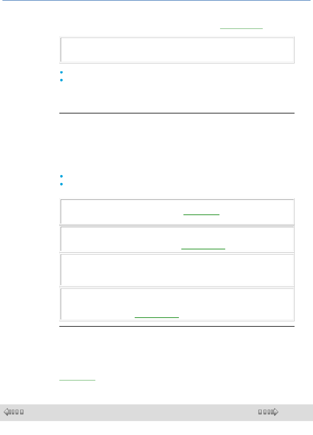
Command Keys
The command keys are the 4 right-hand arrow keys:
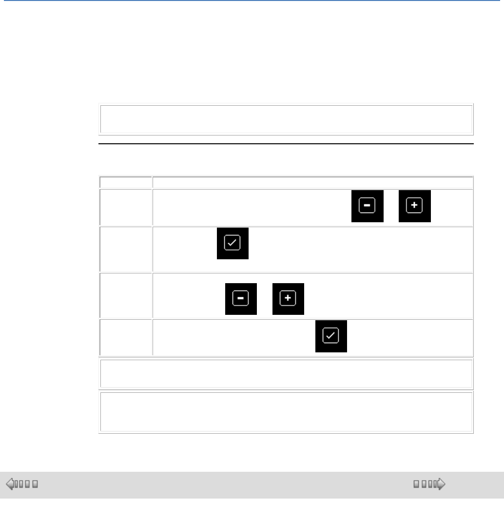
The command keys are described in the table below:
Key
Functions according to the situations
Movement in the screen downwards or to the right
Decrease a previously selected value
Movement in the screen upwards or to the left
Increase a previously selected value
em4 soft Online Help
17
Display of the screen for the menu associated with the field that is flashing
Selection of a value to be modified
Return to the previous menu when the application is OFF
Return to the I/O menu or possibly an active menu when the application is ON
1.2.13 How to Configure an Application from the Controller Front Panel
( § 1.2.12 )
( § 1.2.14 )
Description
Setting the parameters for a user program makes it possible to:
Change the Summer time and Winter daylight saving time switchover settings
Configure each of the functions that make up the application
A function’s parameters can only be set from the controller front panel if Modification
authorized has been checked for this function in the programming workshop.
See PARAMETERS Menu( § 1.3.2 )
1.2.14 How to Dynamically Modify Program Data Using the Controller Front Panel
( § 1.2.13 )
( § 1.2.15 )
Description
Program data can be modified dynamically, using the FBD Display function. See
FBD DISPLAY( § 1.4.2.4.1 )
1.2.15 How to recover the controller resident program in the programming workshop
( § 1.2.14 )
( § 1.2.16 )
Description
See Transferring the program from the controller to the PC ( § 1.5.1.3 )
See Compare the Data in the Controller with the Program( § 1.5.1.5 )
1.2.16 How to Check an Application Using the Programming Workshop
( § 1.2.15 )
( § 1.2.17 )
Overview
The check command launches program compilation.
Two types of check can be used for an application:
The first checks consistency of the diagrams
The second checks the performance of the user application, i.e. the compatibility of:
The memory usage
The user application cycle times
The memory capacities

em4 soft Online Help
18
The controller execution speed
Diagram Consistency Check
Compilation is carried out automatically in the following cases:
Switching from Edit mode to Simulation/Debugging mode
Transferring the program to the controller
Consistency of FBDs: This only concerns SFC network wiring errors. FBD networks
always behave consistently: inconsistent wiring is impossible, and if an input is not
hard-wired it is set to a constant value that does not affect execution of the function or
makes it passive. See the online help for each function.
User Application Performance Check
This appears in the Compilation Result window in the following cases:
Activation of the menu/Controller/Check the program
Switching from Edit mode to Simulation/Debugging mode
Transferring the program to the controller
These performance checks are useful on a simulator as they can be used to obtain a
controller that meets the requirements of the proposed application, once the application
has been created and simulation-tested.
Note: When optional, the window is only displayed when the controller capacities
(memory space and execution speed) are too low in relation to the user program
being checked.
Note: The compilation time for programs that use more than 128 FBDs or SFCs and
numerous loops, may exceed several minutes.
User Application Memory Size Check
The program compiler calculates the volumes used in the different controller memory
zones:
Parameters.
Bit data (block outputs):
Other data (function block outputs).
Program zone: the number of bytes corresponding to all program function blocks
displayed in FBD, and all functions that can be programmed on the selected
controller type (independently of the programming workshop).
In the event of capacity overflow, the window is still displayed and the overflow zones
are shown in red.
The zones shown in blue alert the user to the fact that the size of the application
memory zone concerned is very close to the maximum capacity of the corresponding
memory zone on the selected controller.
User Application Estimated Duration Check
The compiler also calculates the estimated duration of the program by adding together
the individual cycle times of each function used.
The user application runs periodically and its execution period is defined by the user in
the basic cycle( § 1.6.1.1 ) time.
This time corresponds to the minimum sampling period of the controller inputs
(exception: High-speed counter function) and the minimum time for modifying the
output values. The application response time is therefore twice the duration of this
period.
Note: (Take account of the fact that the compiler arranges the functions of an FBD
diagram from inputs to outputs, cutting the loops as close as possible to the outputs
and SFC diagrams from each INIT STEP or RESET INIT, to the downstream steps. )
Not all automation applications need blocking on overrun of the target application
execution period. Indeed, in some cases such blocking is dangerous.
Consequently, the user may decide whether or not to use a WATCHDOG( § 1.6.1.1 )
that will generate an alarm or error if the application is in ON mode on the controller,
when the application cycle time, added to the duration of the processing specific to
em4 soft Online Help
19
operation of the controller and any extensions, exceeds the duration of the selected
period.
A WATCHDOG warning may be returned to an FBD program to enable activation of a
retrieval sequence in the application. This is done using the controller status( §
1.4.2.6.11 ) function.
Note: All functions have a defined maximum cycle time, with one exception in FBD:
The cycle time of the TIME PROG function may vary from 1 to 51 depending on the
number of events used.
To determine the duration of the program execution period, programmers must:
Take into account the estimated duration in the compilation results table.
Carefully read and apply the recommendations written in the online help file:
available duration for the program.
To guarantee a constant program cycle time, you must also carry out appropriate tests
on the controller to verify that alarm or error 505 does not appear.
Duration of Processing Specific to Operation of the Controller and any Extensions
In addition to the processing time for the function blocks contained in the application
program, there are a number of additional processing operations during an execution
period which can easily be defined (as long as fixed) and are therefore taken into
account when calculating the time available for executing the application on each
period (compilation result).
But there are others, which can be either occasional or hard to quantify or account for.
Episodic processes:
Clock management: switch between summer and winter time.
Compensation for clock drift once a week, every Sunday at 1 o'clock in the morning.
The WATCHDOG is always ineffective while one of these operations takes place.
Note: If the application presents no danger to people or equipment in the event of an
increase in the cycle time, simply disable the WATCHDOG( § 1.6.1.1 ). Otherwise,
you must check the maximum execution period.
Note: Modifying parameters using other commands (PARAMETERS, etc.) increases
the application execution period by a variable time. The WATCHDOG is always
ineffective in this controller operating mode (Controller status( § 1.4.2.6.11 )).
Note: In the same way, the display of various data (text, data, hour, date) by active
functions, on the controller LCD display increases the application cycle time by a
variable duration. This duration depends on the type of data to be displayed and, for
the FBD, on the number of DISPLAYS simultaneously active.
Note: In Debugging mode, the cycle times are increased by the communication times
between the PC and the controller. No guarantee can be given concerning the actual
cycle times during this operating mode. The WATCHDOG is always ineffective in this
controller operating mode (Controller status( § 1.4.2.6.11 )).
Maximum Application Execution Period on the Controller Check
Given the problems of accurately estimating the user application cycle time and that of
certain processing operations specific to controller operation, in which increasing the
application execution period may present a danger to people or equipment, you must
perform the relevant tests on the controller to make sure that alarm 505 (cycle overflow)
does not appear, in order to guarantee the maximum cycle time of your program. See
WATCHDOG( § 1.6.1.1 ).
1.2.17 How to check the controller software
( § 1.2.16 )
( § 1.2.18 )
Description
em4 soft Online Help
20
See Controller diagnostics( § 1.5.1.6 )
See Fault menu( § 1.3.4.2 )
1.2.18 How to use the backup memory cartridge
( §
1.2.17 )
( § 1.2.19 )
Description
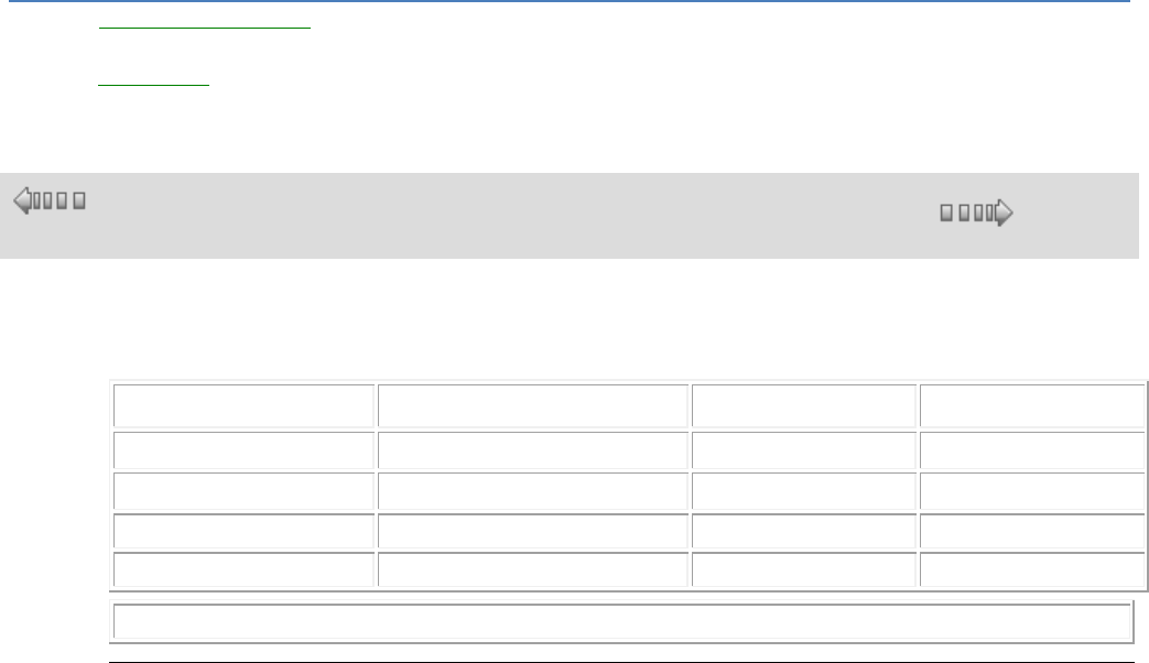
Physical Inputs/Outputs are addressed as "row" "column" depending on their position:
Base
Extension 1
Extension 2
Column
0
1
2
Row
1 ... 9, A..F
1 ... 9, A..F
1 ... 9, A..F
Addressing Inputs
from 0.1 to 0.F
from 1.1 to 1.F
from 2.1 to 2.F
Addressing Outputs
from 0.1 to 0.F
from 1.1 to 1.F
from 2.1 to 2.F
Note: in the workshop, the 0. is implicit for the base
Example with a 16 I/O base and a 10 I/O extension
em4 soft Online Help
21
1.2.19 How to Configure the Language of the Programming Workshop and the Controller
( § 1.2.18 )
( § 1.2.20 )
Description
To configure the language used in the programming workshop and on the controller
front panel, proceed as follows:
Step
Action
1
Use the menu: File ( § 1.6.1.2 ) Preferences ... in the programming workshop.
2
Update the controller software( § 1.5.1.11 ).
1.2.20 How the Controller Behaves in the Event of Power Failure
( § 1.2.19 )
( § 1.2.21 )
Power Failure
A power failure causes the following behavior:
The application is blocked, the controller LCD display freezes, and the buttons stop
working and all controller outputs are deactivated..
em4 soft Online Help
22
The programming software displays the following message: The target peripheral is
not reacting. Check the connection.
All communication stops
The date and time continue to increment during the power failure on controllers
equipped with a clock (battery powered).
Restart Following a Power Failure
The controller checks all its extensions are operating normally, then returns the data
saved on the power failure, and restarts the application execution with a specific
initialization sequence for power return.
This sequence initializes all function inputs and outputs, except the outputs of the
functions protected by a checked Save on power failure parameter.
In this case, these outputs are not reset, and therefore retain the value they had at the
time of the power failure.
To find out which function outputs are protected on power failure, consult the function
description.
1.2.21 How to Import an Application Developed with Millenium 2 into Millenium 3
( § 1.2.20 )
( § 1.2.22 )
Description
See Conversion of Older Applications Using em4( § 1.6.1.7 ).
1.2.22 How to customise the function bar
( §
1.2.21 )
( § 1.3 )
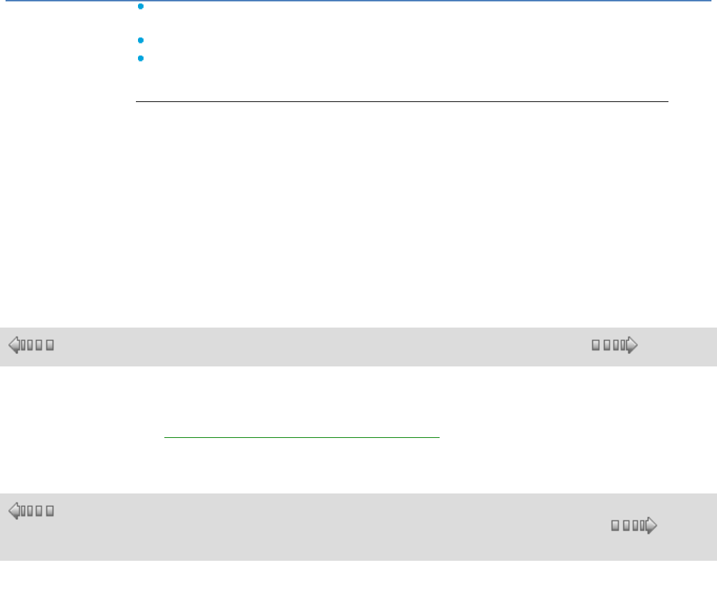
Role and Content of the function bar
To realise a FBD program, the different functions or Macros to be inserted in the wiring sheet are found in
a function bar. A function type is brought together in each of the function bar's tabs.
When the mouse passes over one of the tabs, the dialogue box displays the types of functions that it
contains.
This function bar is divided into four parts:
1 All the manufacturer tabs that contain all the application-specific functions and the standard functions
available with the ClsM3 workshop. These tabs are situated to the left of the function bar.
2 The MACRO tab that contains all the macros archived by the ClsM3 workshop user.
3 The SPE function tab that contains all the application-specific functions for a given user.
4 All the customizable tabs that contain, by type defined by the user, the standard functions, the
application-specific functions and the archived macros.These tabs are situated to the right of the function
bar.
Exemple :
em4 soft Online Help
23
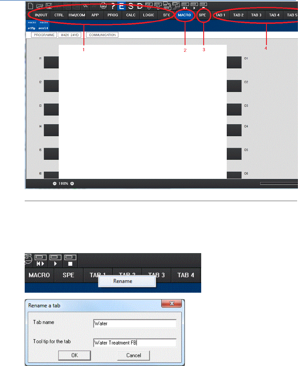
Rename a customizable tab
A customizable tab is selected by a left-click on the mouse above this tab. This displays the tab's content.
A right-click opens a contextual menu.
Activate the Rename command, Enter a name not exceeding 9 characters and confirm your choice by
clicking on OK. The name appears in the tab.
For example: here "Water" and in the tool tip: "Water treatment FB".
em4 soft Online Help
24
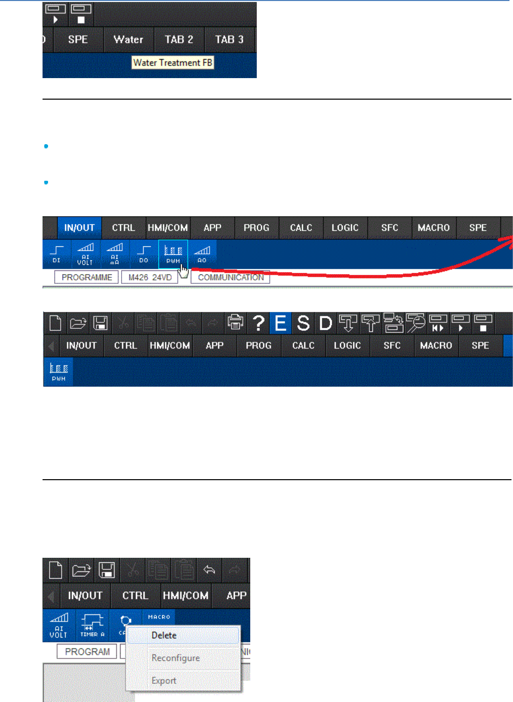
Store the functions and macros in a customizable tab
To store functions or macros in a customizable tab, the user may:
Either select (left-click) a function or a MACRO in one of the manufacturer tabs, in the SPE tab, or in
the MACRO tab and Drag/Drop it on the name of the customizable tab chosen. Scroll down with the
cursor, a "+" appears, release.
Or select (left-click) a function on the wiring sheet and Drag/Drop it to the name of the customizable tab
chosen. Scroll down with the cursor, a "+" appears, release.
Note: the functions will be stored in the customizable tab according to the order in which they have been
introduced into this tab.
Delete the functions and macros in a customizable tab
To remove functions or macros from a customizable tab, the user must select (right-click) a function or a
MACRO in one of the customizable tabs to display the contextual menu and activate the Delete
command.
em4 soft Online Help
25
1.3 Functions Accessible from the Front Panel
( § 1.2.22 )
( § 1.3.1 )
At a Glance
Subject of this Section
What's in this Part?
This part contains the following chapters:
How to Control the Controller from the Front Panel?( § 1.2.12 )
INPUTS-OUTPUTS Screen( § 1.3.1 )
PARAMETER Menu( § 1.3.2 )
RUN/STOP Menu( § 1.3.3 )
SYSTEM Menu( § 1.3.4 )
INTERFACE Menu( § 1.3.5 )
COMMUNICATION Menu( § 1.3.6 )
1.3.1 INPUTS-OUTPUTS Screen
( § 1.3 )
( § 1.3.2 )
Description
The INPUTS-OUTPUTS screen is displayed by default, when no display function (TEXT or
DISPLAY) is active and regardless of:
The programming type
The mode: OFF or ON
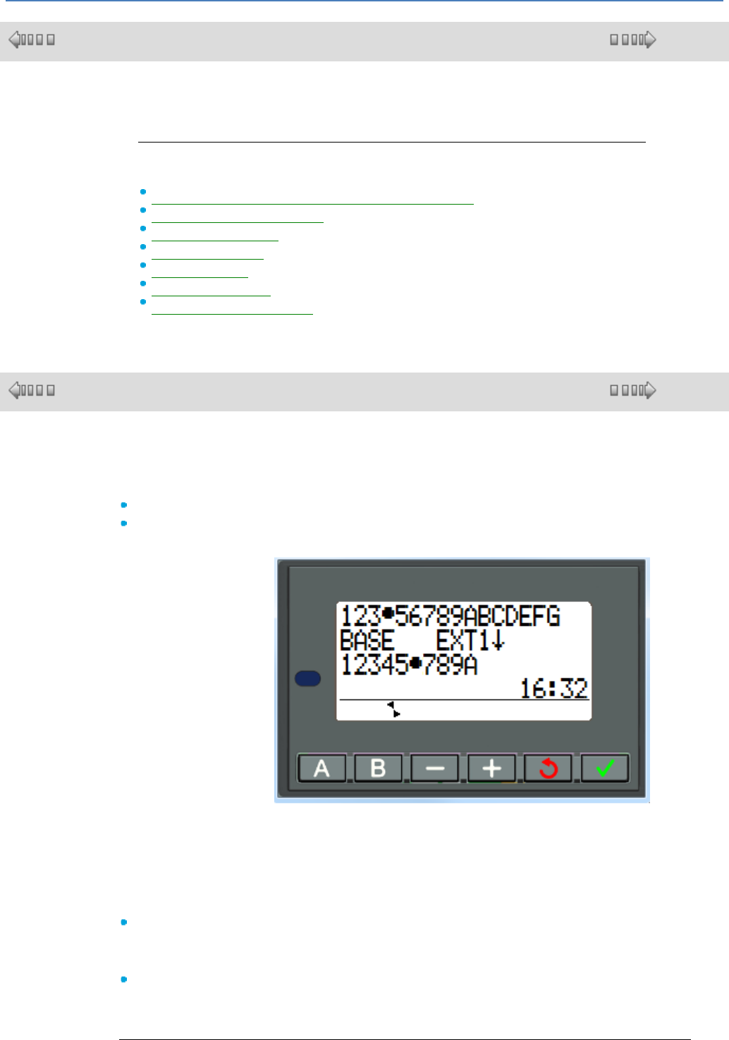
Illustration:
Line 1 : State of inputs:
1 to 9, A to G
Line 2: if there is an
extension (indicated
here by EXT1), the
state of the I/O can be
seen by by pressing the
"-" key
Line 3 : State of
outputs: 1 to 9, A.
Line 4 : Clock.
When the program is in ON mode, active states of the I/O are indicated by a dot (e.g.: input
4, output 6).
INPUTS.
The dot indicates that the bit input is physically at 1. If this input is analog, it is the
switching threshold which is represented.
OUTPUTS.
The dot indicates that the output has been activated by the application but does not
represent the actual output status. For example in the case of an overloaded solid-state
output, it is activated by the application but released by the electronics for safety.
em4 soft Online Help
26
Access to the Main Menu
Pressing the OK key switches the display from the INPUTS-OUTPUTS screen to the main
menu:
PARAMETERS Menu( § 1.3.2 )
ON/OFF Menu( § 1.3.3 )
SYSTEM menu( § 1.3.4 )
INTERFACE Menu( § 1.3.5 )
COMMUNICATION Menu( § 1.3.6 )
Display Functions
The main INPUTS-OUTPUTS screen is replaced by the content of the display functions if a
DISPLAY or TEXT function is active.
If several display functions are active simultaneously, all the blocks are displayed. If there is
any overlap between the fields displayed, the DISPLAY for the highest block number is
shown.
Switching Between Screens
It is possible to go from the DISPLAY or TEXT screen to the INPUTS-OUTPUTS screen
and vice-versa.
To:
proceed as follows:
Display the inputs-outputs screen...
Press and hold down the key .
Go back to the DISPLAY or TEXT
screen...
Release the key
1.3.2 PARAMETERS Menu
( § 1.3.1 )
( § 1.3.3 )
Description
This menu is used to enter and modify the application parameters directly on the screen
using the controller keys.
If there are parameters authorized for changing they are listed in the window; otherwise
a NO PARAMETERS message appears.
Modification is possible in controller ON and OFF mode .
FBD Mode
The FBD functions with modifiable parameters are the following:
Numerical Constant-Type (NUM) Inputs( § 1.4.2.3.6 ),
Clocks (Time Prog)( § 1.4.2.3.14 ),
Gain( § 1.4.2.7.1 ),
Timers( § 1.4.2.3.1 ): TIMER A/C, Timer BW, TIMER B/H, TIMER Li, Totalisers,
Counters: PRESET COUNT( § 1.4.2.3.16 ),
CAM block( § 1.4.2.5.1 ),
Preset H-Meter( § 1.4.2.3.18 ),
Only the functions used in the program, that have parameters, and whose option
Authorized Modification option is enabled are listed in the PARAMETER menu.
Parameter Modification
Parameter modification procedure:
Step
Action

em4 soft Online Help
27
1
Place the cursor over the PARAMETERS menu in the main menu (PARAMETERS
flashing) and confirm by pressing the OK button .
Result: the parameters window opens to the first parameter.
2
Select the block to modify:
place the cursor over the number of the function block,
press the OK button,
Use the and keys to scroll through the function block numbers, until
you reach the right one,
confirm by pressing the OK button.
3
Select the name of the parameter to modify:
place the cursor over the name of the parameter of the function block,
press the OK button,
Use the and keys to scroll through the names of the parameters, until
you reach the right one,
confirm by pressing the OK button.
4
Select the value of the parameter to modify:
Place the cursor over the value to modify.
press the OK button,
Use the and keys to scroll through the possible values, until you reach
the right one,
confirm by pressing the OK button.
5
Repeat steps 2, 3 and 4 for each to the functions to modify.
6
Press twice on the ESC button to return to Inputs/Outputs screen.
1.3.3 ON/OFF Menu
( § 1.3.2 )
( § 1.3.4 )
Description
This function is used to start or stop the program in the controller:
In OFF mode: The program is stopped and the outputs disabled.
In ON mode (with or without initialization of saved parameters): The program is
executed.
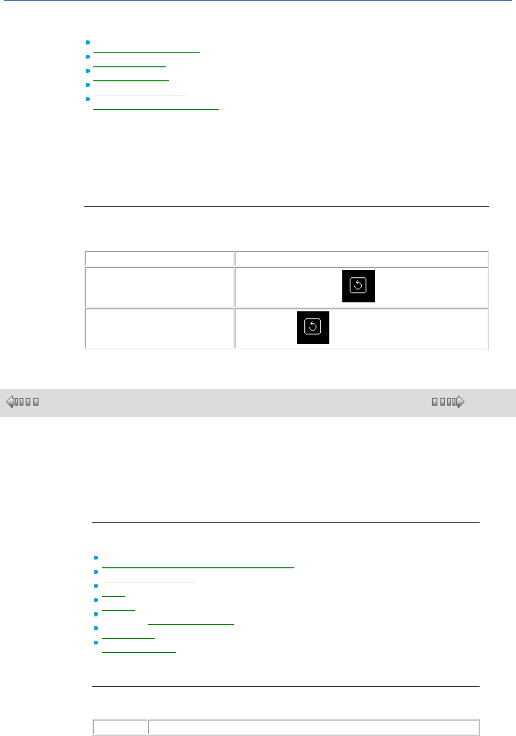
Startup
In OFF mode, when the ON/OFF menu is accessed, the interface offers the user the
following 3 choices to start the program:
ON: The current values for which the Save on power failure option was activated are
maintained.
RESET SAVED VALUES AND START: All current values (counters, timers, etc.) are
reset before the program starts (default selection).
CANCEL: The program is not started.
Illustration:
em4 soft Online Help
28
The navigation keys (+, -) are used to change the selection.
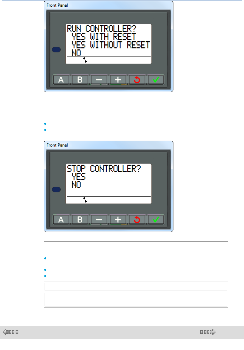
Off
In ON mode, when the ON/OFF menu is accessed, the interface offers the user the
following 3 choices to start the program:
YES : the controller changes to OFF then back to the previous menu
NO : the controller stays ON then back to the previous menu
Illustration :
The navigation keys (+, -) are used to change the selection.
Case of the LED
The LED on the front panel of the controller acts as an indicator light:
If the LED flashes slowly (3 Hz), the controller is OFF (even if there is a non-blocking
fault).
If the LED flashes quickly (5 Hz), the controller is OFF with a fault.
If the LED remains on, the controller is powered up and ON.
Note: On power-up, the controller is ON, except in the event of a blocking fault.
Note: To acknowledge a blocking fault, power down the controller, then power it up
again.
1.3.4 SYSTEM Menu
( § 1.3.3 )
( § 1.3.4.1 )
em4 soft Online Help
29
At a Glance
Subject of this Chapter
The SYSTEM menu gives access to the following functions:
CLOCK( § 1.3.4.1 )
FAULT( § 1.3.4.2 )
VERSION( § 1.3.4.3 )
Note: use the navigation key to return to the main menu .
1.3.4.1 CLOCK Menu
( § 1.3.4 )
( § 1.3.4.1.1 )
At a Glance
Subject of this Chapter
The CLOCK menu provides access to the following functions:
CHANGE DAY/HOUR Menu( § 1.3.4.1.1 )
CHANGE SUMMER/WINTER Menu( § 1.3.4.1.2 )
Note: use the navigation key to return to the main menu .
1.3.4.1.1 CHANGE DATE/TIME Menu
( § 1.3.4.1 )
( § 1.3.4.1.2 )
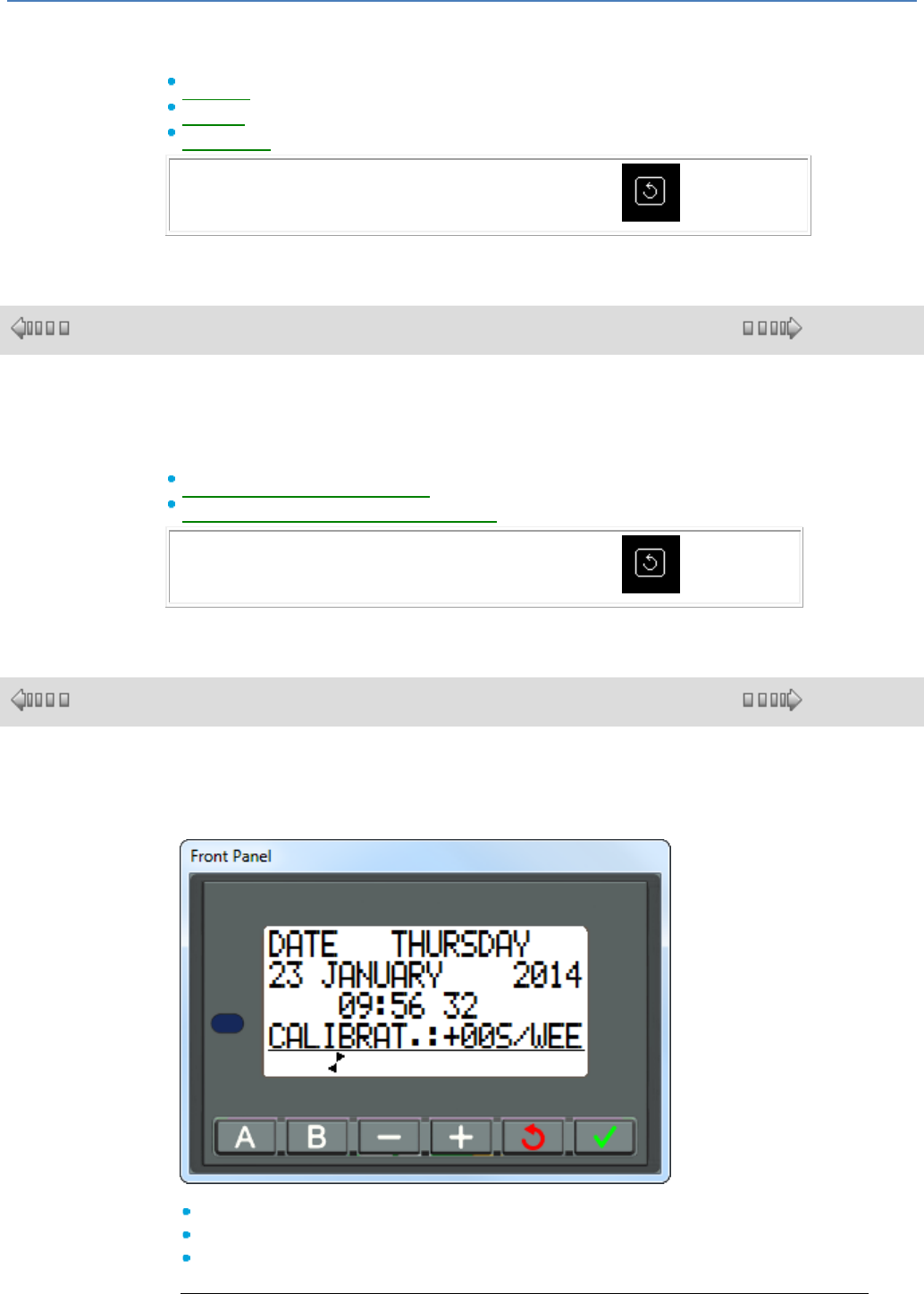
Description
This function is used to configure the date and time on controllers that have a clock.
Illustration:
The modifiable parameters are:
Day/month/year
Hour, minutes, seconds
CALIBRAT: Calibration of the controller internal clock in seconds per week
Clock Calibration
em4 soft Online Help
30
The quartz that controls the controller's real-time clock has a variable monthly drift
depending on the environmental conditions in which the controller is used.
The maximum value for this drift is approximately one minute per month.
To estimate this drift, observe the drift on the controller clock compared to a standard
reference clock for a few weeks or more.
Example:
If you wish to compensate this drift, you can, for example, make a -15 second
correction per week to compensate for a + 60 second drift per month. This
compensation is executed on Sunday at one o'clock in the morning.
Note: This correction will be pointless if the controller is subject to prolonged power
failures or to signification temperature variations.
Clock Configuration
Procedure:
Steps
Description
1
Select the parameter to modify using the navigation keys and .
2
Press the OK key .
Result: The selected parameter flashes.
3
Modify the parameter value.
The navigation keys and are used to change the current value.
4
Confirm your changes by pressing the OK key .
Note: The controller contains a software module that determines the day of the week
when the user selects the day of the month in the year.
Note: You are not allowed to modify the time on a product between 02.00 and 03.00
in the morning on the changeover days from summer to winter time (at 03.00 it is
02.00).
1.3.4.1.2 CHANGE SUMMER/WINTER Menu
( § 1.3.4.1.1 )
( § 1.3.4.2 )
Description
This function is used to change the daylight saving time automatically
(summer/winter) for controllers with a clock.
Illustration:

em4 soft Online Help
31
The possible operating modes are as follows:
DISABLED: no change
Depending on the zone: The change takes place automatically, the dates are
preset according to the geographic zone:
EUROPE, or
USA
MANUAL: The change takes place automatically, but you must specify the date of
the change, for both summer and winter, as follows:
Month: MONTH
Number of the Sunday in the month: SUN No. (1, 2, 3, 4 or 5)
Configuring the Time Change
To configure a time change, proceed as follows:
Step
Action
1
Select the parameter to modify using the navigation keys and .
2
Press the green OK key .
Result: The selected parameter flashes.
3
Modify the parameter value.
The keys and are used to change the current value.
4
Confirm your changes by pressing the green OK key .
Note: You are not allowed to modify the time on a product between 02.00 and
03.00 in the morning on the changeover days from summer to winter time (at
03.00 it is 02.00).
1.3.4.2 FAULT Menu
( § 1.3.4.1.2 )
( § 1.3.4.3 )
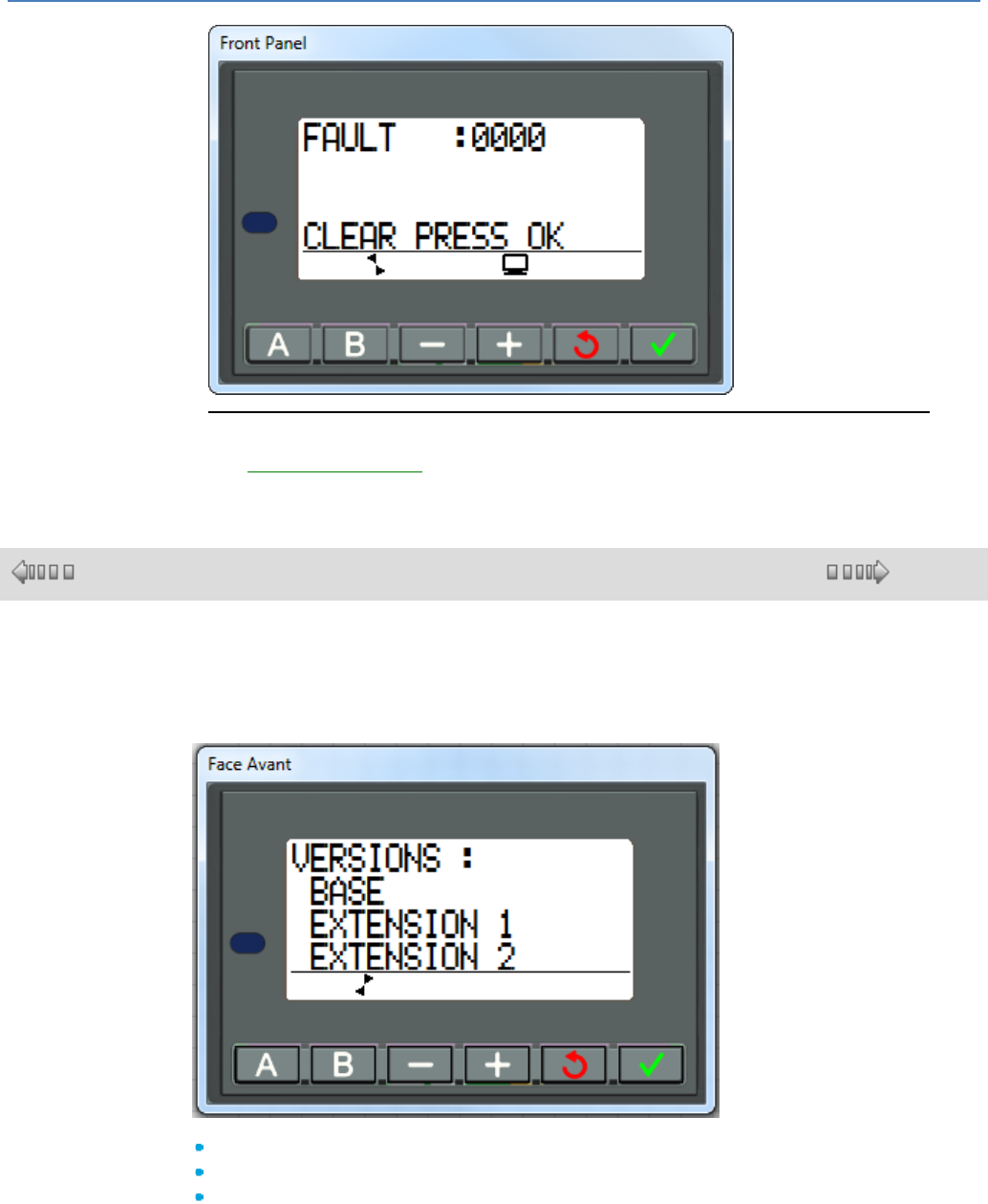
Description
When a fault is detected by the controller software, an icon appears at the bottom of
the screen. The FAULT menu is used to display the type of fault: error or warning,
cycle overflow, basic cycle time too long, etc.).
em4 soft Online Help
32
Illustration:
Description of Errors
See Description of Errors( § 1.6.1.12 )
1.3.4.3 VERSION Menu
( § 1.3.4.2 )
( § 1.3.5 )
Description
This function is used to identify the module with its hardware and software
versions:
Illustration :
An initial menu is used to select:
BASE
EXTENSION 1
EXTENSION 2
The scroll buttons (+,-) are used to change the selection.
To quit, press the ESC button; the display returns to the screen of the version
menu.
Example with BASE selected:
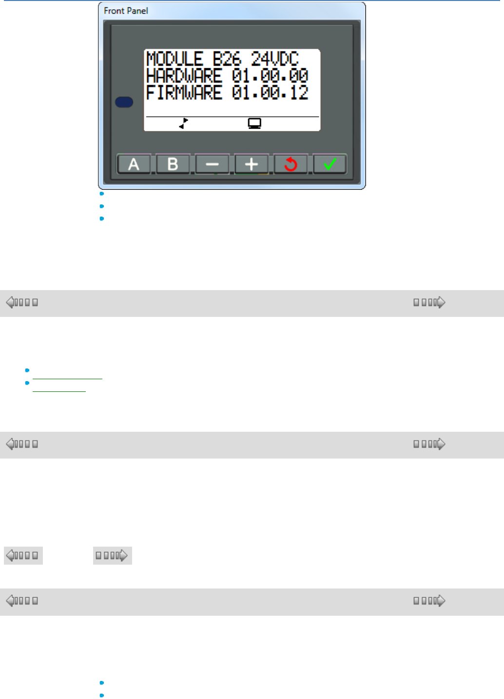
em4 soft Online Help
33
MODULE: module type
HARDWARE: hardware version
FIRMWARE: controller firmware version
To quit, press the ESC button; the display returns to the screen of the version
menu.
1.3.5 ACCESSORY Menu
( § 1.3.4.3 )
( § 1.3.5.1 )
What's in this Chapter
This chapter contains the following topics:
MODBUS Menu( § 1.3.5.1 )
SAVE Menu( § 1.3.5.2 )
1.3.5.1 MODBUS Menu
( § 1.3.5 )
( § 1.3.5.2 )
Description
This function can be used to change the slave number from 1 to 247.
1.3.5.2 SAVE Menu
( § 1.3.5.1 ) ( § 1.3.6 )
1.3.6 COMMUNICATION Menu
( § 1.3.5.2 )
( § 1.3.6.1 )
Overview
Aim of This Chapter
The COMMUNICATION menu provides access to the following functions:
PARAMETERS,
INFORMATION.
This chapter describes the characteristics of these functions.
em4 soft Online Help
34
Note: use the navigation key to return to the main menu .
What's in this Chapter
This chapter contains the following topics:
PARAMETERS menu( § 1.3.6.1 )
INFORMATION menu( § 1.3.6.2 )
1.3.6.1 PARAMETERS
( § 1.3.6 )
( § 1.3.6.2 )
Description
The PARAMETERS menu provides access to the following functions:
PIN CODE.
The PIN CODE is supplied by the operator in the form of 4 digits.
- Select the digit using the + and - buttons
- OK: the digit blinks
- + or - to increment or decrement the digit
- once all 4 digits have been entered, go to VALIDATE and confirm with OK.
Note: use the navigation key to return to the main menu .
1.3.6.2 INFORMATION
( § 1.3.6.1 )
( § 1.4 )
Description
The INFORMATION menu provides information about communication:
PLMN,
POWER RECEIVED,
IMEI,
MSISDN,
URL NUMBER,
APN
This chapter describes the characteristics of
these functions.
Note: use the navigation key to return to the
main menu .
- PLMN: operator name
- Power received: this is expressed in dB
- IMEI: unique radio module number
- MSISDN: SIM card telephone number
- Port: not used

em4 soft Online Help
35
- URL number: not used
- APN: Operator access point for data exchanges,
for example 'orange.m2m.spec'
1.4 FBD Language
( § 1.3.6.2 )
( § 1.4.1 )
At a Glance
Subject of this Section
This section describes the use of FBD (Functional Block Diagram) programming
language for the controller.
What's in this Part?
This part contains the following chapters:
Overview of FBD language( § 1.4.1 )
FBD Language Elements( § 1.4.2 )
FBD Programming( § 1.4.3 )
Example of an FBD Application( § 1.4.4 )
1.4.1 Overview of FBD language
( § 1.4 )
( § 1.4.1.1 )
At a Glance
Subject of this Chapter
This chapter provides a general description of FBD language.
What's in this Chapter?
This chapter contains the following topics:
FBD Program Edit Window( § 1.4.1.1 )
Function Bar( § 1.4.1.2 )
1.4.1.1 FBD Program Edit Window
( § 1.4.1
)
( § 1.4.1.2 )
Overview
FBD mode allows graphic programming based on the use of predefined function blocks and pre-defined
or archived Macros.
In FBD programming, there are two types of window and two displays:
The edit window
Program view
Settings view
The supervision( § 1.4.1.1 ) window
Edit Window in Program View
The FBD programs are created in the edit window in Program view. This can be accessed by using the
em4 soft Online Help
36
button.
The edit window is made up of three zones:
The wiring sheet, where the functions and Macros that make up the program are inserted.
The Inputs zone on the left of the wiring sheet where the inputs are positioned.
The Outputs zone on the right of the wiring sheet where the outputs are positioned.
The I/O are specific to the type of controller and extension chosen by the user.
The program in the edit window corresponds to the program that is:
compiled
transferred to the controller
compared to the contents of the controller
used in simulation mode
used in supervision mode
used in debugging mode
The figure below shows an example of an edit window in FBD language:
The table below lists the different elements in the edit window:
Number
Description
1
Function block input zone.
2
Connection between two function blocks.
3
Function bar.
4
Function block.
5
Wiring sheet.
6
Function block number.
7
Output function block zone.
8
Zoom
9
Memory capacity of specific functions
Details of FB
em4 soft Online Help
37
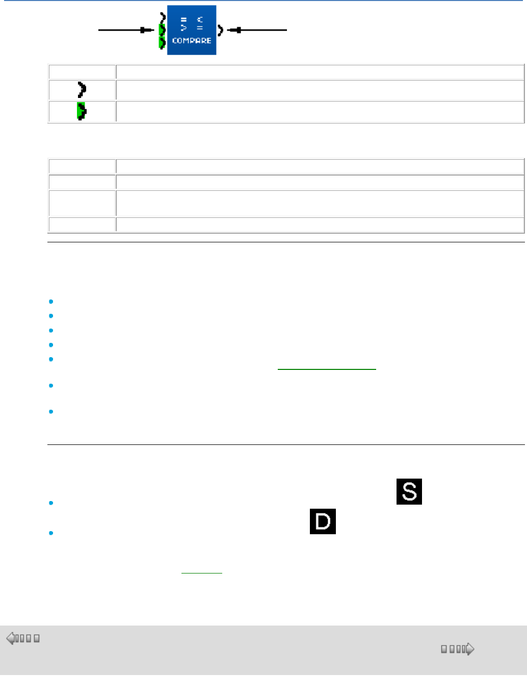
FB Inputs
FB Outputs
Symbol
Description
1 bit
16 bits
There is a Validation input on the top left of the FB for the most part of function blocks.
This input functions as follows :
State
Status
0
No validated
1 ou Not
connected
Validated
0 → 1
Memorization of outputs in the current state
Edit Window in Settings View
Settings view can be accessed in Edit mode via the Display/Settings View menu. It is used to list all
automation functions with parameters used in the application.
The general interface allows the user to view all the information:
Block: function block diagram
Function: Timer, Counter, etc.
Block num: function block ID
Parameters: the target value for a counter, etc. ,
Save on power failure: indicates whether the Save on power failure( § 1.2.20 ) option has been
selected
Modification authorized: indicates whether or not parameter modification is possible from the
controller front panel
Comment : comments associated with the function.
To adjust the various parameters, double-click on the desired line.
Supervision Window (not available in this version)
The Supervision window can also be accessed from the following modes:
Simulation : the Mode/Simulation menu or using the simulation button on the controller bar
Debugging Mode/Debugging menu or by using the debugging button on the controller bar
It contains the functions, without their connections, that the programmer has extracted (using Drag/Drop
or Copy/Paste) from the edit window.
The window can also contain drawings( § 1.4.3.1.6 ), text and images.
In simulation and debugging mode the parameters and outputs of the functions present are updated.
1.4.1.2 Function Bar
( §
1.4.1.1 )
( § 1.4.2 )
At a Glance
To create an FBD program, the different functions or Macros to be inserted in the wiring sheet are
available in a function bar. Each of the tabs in the function bar groups a function type.
When the mouse is moved over one of the tabs, the dialog box displays the type of functions that it
em4 soft Online Help
38
contains.
This function bar is divided into four parts:
All the manufacturer tabs that contain all the application-specific functions and the standard
functions available with the workshop. These tabs are situated to the left of the function bar.
the SPE function tab that contains all the application-specific functions for a given user.
The MACRO function tab that contains all the Macros archived by the workshop user.
All the customizable tabs that contain, by type defined by the user, the standard functions, the
application-specific functions and the archived macros.These tabs are situated to the right of the
function bar.
The standard or application-specific functions and Macros that are incompatible with the controller's
choice are shown with dark grey shading.
Examples of tabs in the function bar
Important note: these examples are non-contractual and are subject to future developments
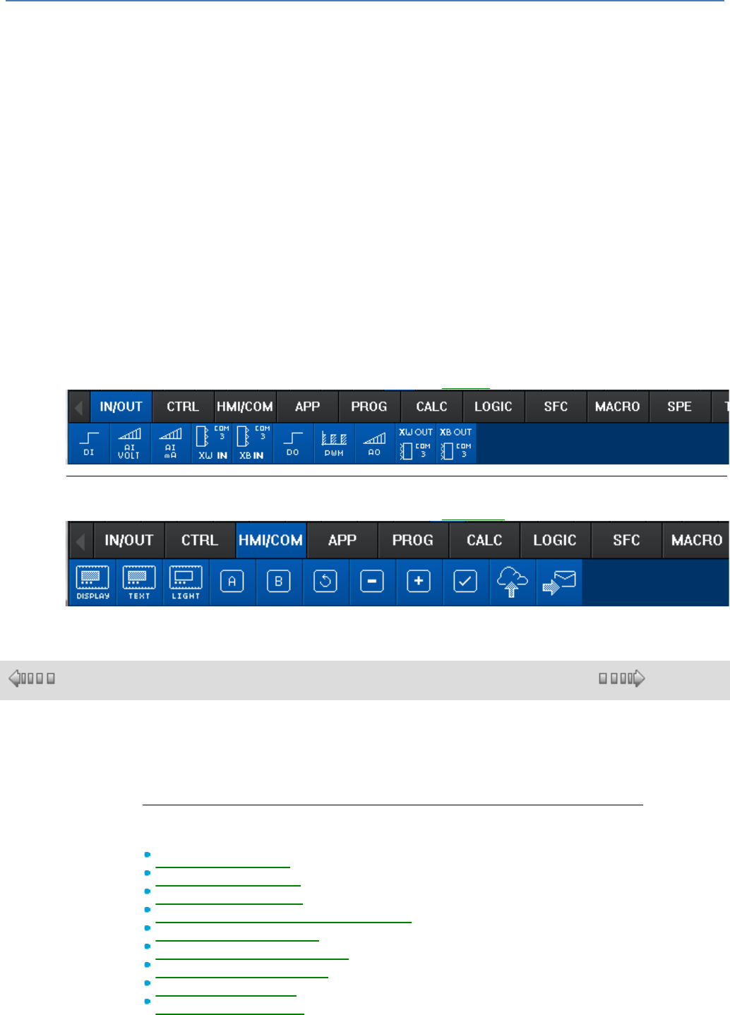
IN/OUT Functions Bar
The following figure shows an example of the content of the IN/OUT( § 1.4.2.1 ) function tab:
HMI/COM Functions bar
The following figure shows an example of the content of the HMI/COM function tab:
1.4.2 FBD Language Elements
( § 1.4.1.2 )
( § 1.4.2.1 )
At a Glance
Subject of this Chapter
This chapter describes the different elements of the FBD language.
What's in this Chapter?
This chapter contains the following sections:
Different Input Blocks( § 1.4.2.1 )
Different Output Blocks( § 1.4.2.2 )
CTRL functions: control( § 1.4.2.3 )
HMI/COM functions: HMI/communication( § 1.4.2.4 )
APP functions: application( § 1.4.2.5 )
PROG functions: programming( § 1.4.2.6 )
CALC functions: calculation( § 1.4.2.7 )
LOGIC functions: logic( § 1.4.2.8 )
SFC functions (Grafcet)( § 1.4.2.9 )
em4 soft Online Help
39
1.4.2.1 Different Input Blocks
( § 1.4.2 )
( § 1.4.2.1.1 )
At a Glance
Subject of this Section
This section describes the different input blocks available using FBD language.
What's in this Section?
This section contains the following topics:
Discrete-type (digital)( § 1.4.2.1.1 ), voltage analog( § 1.4.2.1.2 ), current analog( §
1.4.2.1.3 ), network inputs( § 1.4.2.1.4 ).
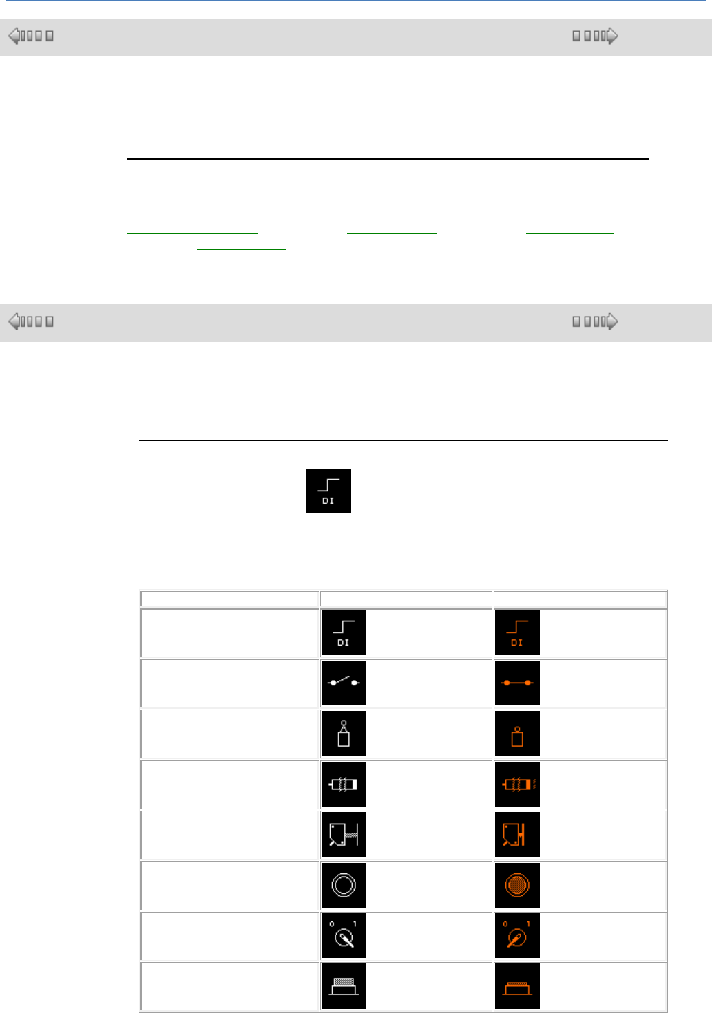
1.4.2.1.1 Discrete-Type Inputs
( § 1.4.2.1 )
( § 1.4.2.1.2 )
At a Glance
The Discrete-type input is available for all controller types. Discrete inputs can be
arranged over all the controller inputs.
Access
The Discrete input function is accessible in the IN/OUT function bar.
Type of Discrete Inputs
The Digital input type can be selected from the Parameters window, comments tab.
This is then displayed in the edit and supervision windows.
Type
Display in the Inactive state
Display in the Active state
Discrete input
Contact
Limit switch
Proximity sensor
Presence sensor
Illuminated pushbutton
Selector switch
Pushbutton
em4 soft Online Help
40
Normally open relay
Custom Image
It is also possible to import a customized image, one for the inactive state and one for
the active state. The size of this image should be the smallest possible (several Kb).
Standard format: 43x43 .bmp .jpg .gif
Filtered Discrete-Type Input
A filter can be selected from the Parameters window. Behind the Discrete input, a
filter is added to reduce or even eliminate disturbances.
A Discrete input is filtered using a constant level detection algorithm (1 or 0) on the
"sensor" signal, measured over a certain time frame. If the signal is stable throughout
the entire detection period, the output of the symbol from the filtered Discrete input
takes the value of the measured signal. Otherwise it remains unchanged.
The filtered Discrete inputs can be arranged at any controller input.
The value of the parameter (between 1 and 255) entered in the Parameters window
may be used to define the minimum time during which the signal must be stable. This
value is a multiple of the duration of the basic cycle( § 1.6.1.1 ) of the controller.
Etat de l'entrée
It is also possible to change the input state:
NO: normally open
NC: normally closed
Simulation and Debugging Modes
In Simulation or Debugging modes it is possible to force the digital inputs. In this case,
the input symbol is displayed as shown in the above table.
1.4.2.1.2 Analog voltage Input
( § 1.4.2.1.1
)
( § 1.4.2.1.3 )
Overview
The Voltage analog type input is available on all types of controller supplied with a DC
voltage.
The Voltage analog input voltage is converted into a numerical integer value by a 12-
bit analog to digital converter. The integer value of the output is between 0 and 4095.
Analog inputs can only be arranged on the inputs between I5 and IG.
Access
The Voltage analog input function is accessible from the IN/OUT window.
Parameter
By default, this voltage varies between 0 and 10V DC.
The type of electrical connection at the input can be configured in the Parameters
window:
0 - 10 V
0 - 30 V or potentiometer, selected if the input is connected to a potentiometric
device with a power supply between 0 Volts and the controller supply voltage
Types of Analog Input
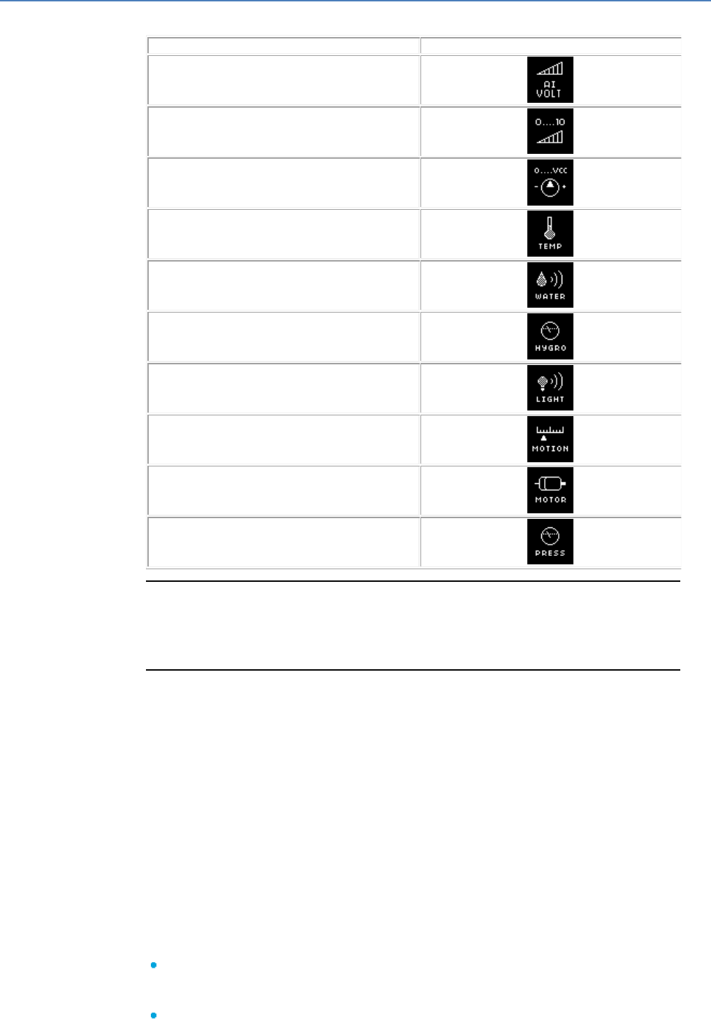
em4 soft Online Help
41
The Analog input type can be selected from the Parameters window, comments tab.
This is then displayed in the edit and supervision windows.
Type
Display in edit mode
Input (by default)
Input
Potentiometer
Temperature
Water
Hygrometry
Light
Motion
Motor
Pressure
Custom Image
It is also possible to import a customized image from the Comments window. The
size of this image should be the smallest possible (a few Kb).
Standard format: 43x43 .bmp .jpg .gif
Filtered Analog Input
A filter can be selected from the Parameters window.
Behind the analog input, a low pass filter is added. This function is available on all the
types of controllers supplied with a DC voltage.
The Analog input voltage is converted into a digital integer value by a 12-bit
analog/digital converter. The whole output value is between 0 and 4095.
The Analog inputs can only be placed on the inputs numbered from I5 to IG.
A low pass filter restores the entire input signal (frequency, amplitude and phase-
shift), whose frequency is considerable lower, to a typical filter frequency, called a cut-
off frequency. When the frequency of the input signal nears the cut-off frequency,
the output signal, of the same frequency, becomes increasingly lower and phase-
shifted. When the frequency of the input signal is equal to the cut-off frequency, the
output signal is lowered by around 30%, and phase-shifted by 45º. For a frequency
above and rising from the cut-off frequency, the reduction becomes greater (until it
reaches total elimination) and the phase-shifting approaches 90º.
The Parameters window is used to define:
The input voltage. By default, this voltage varies between 0 and 10Vdc. The
potentiometer is chosen if the input is connected to a potentiometer device
powered between 0 volts and the voltage of the controller power supply.
The cut-off frequency of the low pass filter (between 0.06 and 88.25 Hz)
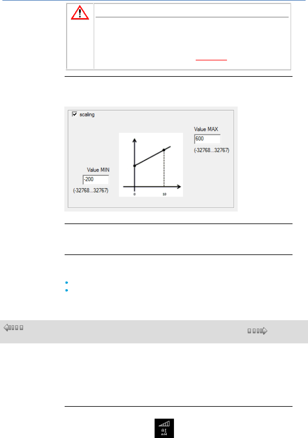
em4 soft Online Help
42
CAUTION
The potentiometer option is selected if the input is connected to a
potentiometric device supplied between 0 Volts and the tester
supply voltage.
Whenever a modification is made to the basic cycle time, you must check
or modify the cut-off frequency
Failure to follow these instructions can result in injury or
equipment damage.
Scaling
A scale can be selected from the Parameters window.
For example here with a sensor from -20°C to + 60°C in 1/10ths of a °C.
Simulation and Debugging Modes
In Simulation or Debugging modes it is possible to force (between 0 and 4095 ) the
output of the analog inputs.
Delay in Availability of Measurements
The availability of analog input measurements is delayed by a few ms in the following
situations:
Power return following a power cut
Variation between 0 and full scale
1.4.2.1.3 Analog current Input
( § 1.4.2.1.2
)
( § 1.4.2.1.4 )
Overview
The Current analog type input is available on all types of controller supplied with a DC
voltage.
The analog input current is converted into an integer digital value by an 11-bit analog
to digital converter. The integer value of the output is between 0 and 2000 (20mA).
Current analog inputs can only be arranged on the inputs between ID and IG.
Access
The Current analog input function is accessible from the IN/OUT window.
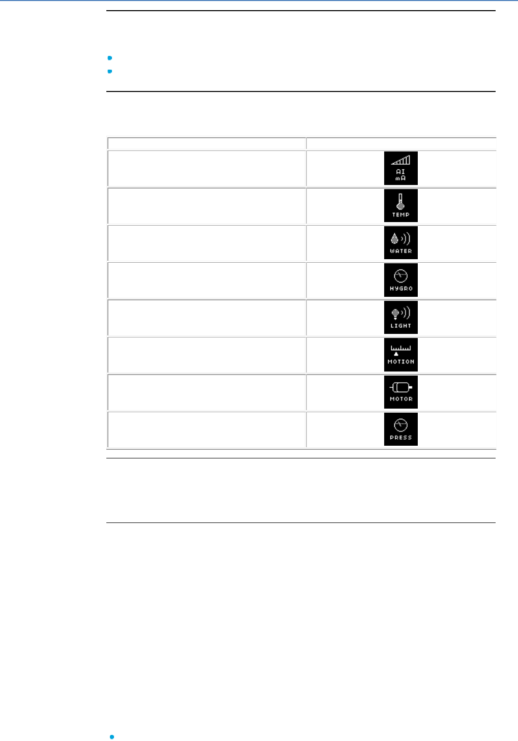
em4 soft Online Help
43
Parameter
By default this current varies between 0 and 20 mA.
The type of acquisition can be configured in the Parameters window:
0 - 20 mA
4 - 20 mA
Types of Analog Input
The Analog input type can be selected from the parameter setting window,
comments tab. This is then displayed in the edit and supervision windows.
Type
Display in edit mode
Input (by default)
Temperature
Water
Humidity
Light
Movement
Motor
Pressure
Custom Image
It is also possible to import a customized image from the Comments window. The size
of this image should be the smallest possible (a few Kb).
Standard format: 43x43 .bmp .jpg .gif
Filtered Analog Input
A filter can be selected from the Parameters window.
Behind the analog input, a low pass filter is added. This function is available on all the
types of controllers supplied with a DC voltage.
The analog input current is converted into an integer digital value by an 11-bit analog
to digital converter. The integer value of the output is between 0 and 2000.
The Analog inputs can only be placed on the inputs numbered from ID to IG.
A low pass filter restores the entire input signal (frequency, amplitude and phase-
shift), whose frequency is considerable lower, to a typical filter frequency, called a cut-
off frequency. When the frequency of the input signal nears the cut-off frequency,
the output signal, of the same frequency, becomes increasingly lower and phase-
shifted. When the frequency of the input signal is equal to the cut-off frequency, the
output signal is lowered by around 30%, and phase-shifted by 45º. For a frequency
above and rising from the cut-off frequency, the reduction becomes greater (until it
reaches total elimination) and the phase-shifting approaches 90º.
The Parameters window is used to define:
The input current. By default this current varies between 0 and 20 mA.
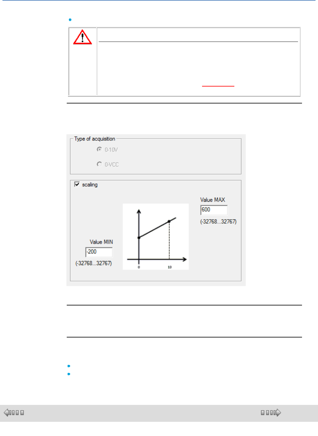
em4 soft Online Help
44
The 4 - 20 mA option is used to manage the bit at the output of the input plot. This
bit is set to 1 if the current is less than 4 mA.
The cut-off frequency of the low pass filter (between 0.06 and 88.25 Hz)
CAUTION
The potentiometer option is selected if the input is connected to a
potentiometric device supplied between 0 Volts and the tester
supply voltage.
Whenever a modification is made to the basic cycle time, you must check
or modify the cut-off frequency
Failure to follow these instructions can result in injury or
equipment damage.
Scaling
A scale can be selected from the Parameters window.
For example here with a sensor from -20°C to + 60°C in 1/10 of a °C and a 4-20 mA
acquisition type.
Simulation and Debugging Modes
In Simulation or Debugging modes it is possible to force (between 0 and 2000) the
output of the analog inputs.
Delay in Availability of Measurements
The availability of analog input measurements is delayed by a few ms in the following
situations:
Power return following a power cut
Variation between 0 and full scale
1.4.2.1.4 Network Input
( § 1.4.2.1.3 )
( § 1.4.2.2 )
Description
The XWIN, XBIN network input function blocks are used to receive, via a
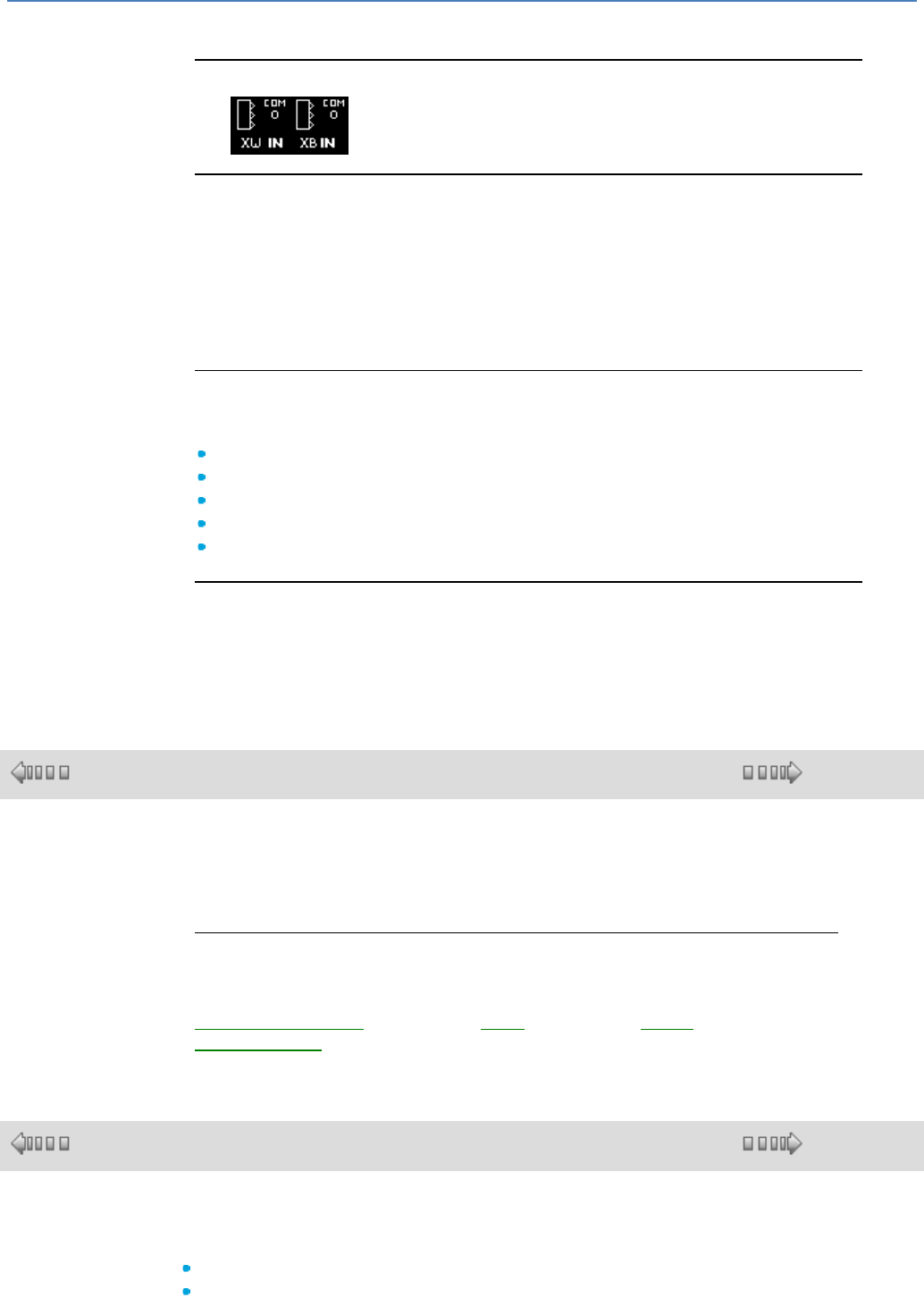
em4 soft Online Help
45
communication port, data destined for memory space in the controller's fixed
addresses.
Access
The functions can be accessed from the IN/OUT function bar.
Inputs/Outputs
The function delivers eight output values (16 bits or 1 bit depending on the FB)
called Value 1 to Value 8. These outputs allow the application programmed in the
controller to use the data sent by the network (COM 0 to COM 3).
COM 0: communication port of the accessory, e.g. Modbus.
COM 1: communication port of extension 1
COM 2: communication port of extension 2
COM 3: communication port of the base card, e.g. 2G, 3G, Ethernet network.
Parameters
The user selects a range of eight addresses from the Parameters window. The
address ranges available are as follows:
XWIN
1 - 8
XWIN
9 - 16
XWIN
17 - 24
XBIN
25-1
XBIN
25-2
Parameters file
This file, in XML format, associates a label that can be used by all the network
devices with each data item.
The label is a character string.
1.4.2.2 Different Output Blocks
( § 1.4.2.1.4 )
( § 1.4.2.2.1 )
At a Glance
Subject of this Section
This section describes the different output blocks available using FBD language.
What's in this Section?
This section contains the following topics:
Discrete-type (digital)( § 1.4.2.2.1 ), PWM( § 1.4.2.2.2 ), analog( § 1.4.2.2.3 ),
network outputs( § 1.4.2.2.4 ).
1.4.2.2.1 Discrete-Type Outputs
( § 1.4.2.2 )
( § 1.4.2.2.2 )
At a Glance
The controllers feature two types of Discrete outputs:
Solid state outputs,
Relay outputs.

em4 soft Online Help
46
Access
The Discrete output function is accessible from the IN/OUT window.
Types of Discrete Outputs
The Digital output type can be selected from the Parameters window, comments
tab. This is then displayed in the edit and supervision windows.
The selection is made using the output's inactive-state symbol.
Type
Display in the Inactive state
Display in the Active state
Discrete Output
Normally open relay
Lamp
Valve
Audible signal
Green indicator light
Red indicator light
Orange indicator light
Heating
Fan
Custom Image
It is also possible to import a customized image, one for the inactive state and one for
the active state. The size of this image should be the smallest possible (several Kb).
Standard format: 43x43 .bmp .jpg .gif
Simulation and Debugging Modes
In Simulation or Debugging modes, outputs are displayed in the active or inactive
state with their corresponding symbols (shown in the table above).
Note : To avoid an error (Warning n°6), you have to connect power supply of the
static outputs before or at the same time with the product supply.
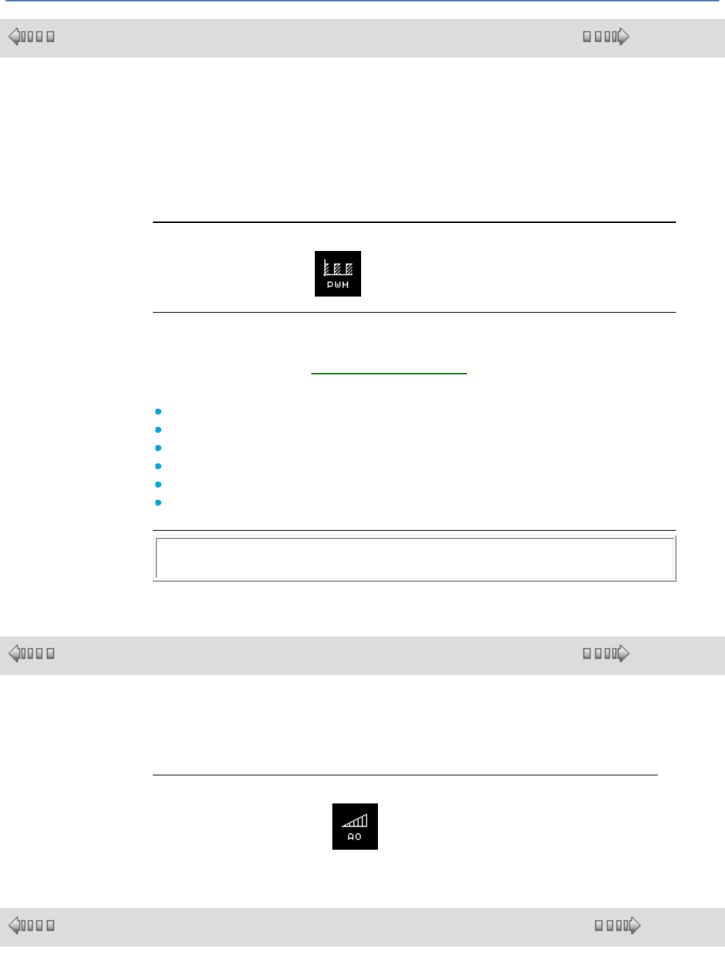
em4 soft Online Help
47
1.4.2.2.2 PWM-Type Output
( § 1.4.2.2.1 )
( § 1.4.2.2.3 )
Overview
The controller has 2 discrete solid state outputs (O1, O2) that can be controlled
using PWM (pulse width modulation).
The mean value of the PWM output voltage is then proportional to the setpoint.
This enables a value between 0 and 100% of its maximum value to be controlled
using a discrete output. 0% corresponds to setpoint 0 and 100% corresponds to
setpoint 100.
Access
The PWM output function can be accessed from the IN/OUT function bar.
Frequencies
The basic frequency of all the PWM-type controller outputs can be set from the
Configuration tab of the Program Configuration( § 1.6.1.1 ) window.
The Frequency of all controller PWMs parameter enables the basic frequency for
PWM-type outputs to be selected from the following values:
1758 Hz
452 Hz
226 Hz
113 Hz
56 Hz
14 Hz
Note : To avoid an error (Warning n°6), you have to connect power supply of the
static outputs before or at the same time with the product supply.
1.4.2.2.3 Analog Type Output
( § 1.4.2.2.2 )
( § 1.4.2.2.4 )
At a Glance
Analog outputs are available on some extension models. The 0 to 10V outputs
are on 10 bits from 0 to 1023
Access
The Discrete output function is accessible from the IN/OUT window.
1.4.2.2.4 Network Output
( § 1.4.2.2.3 )
( § 1.4.2.3 )
Description
The XWOUT, XBOUT network output function blocks are used to transmit, via a
communication port, data.
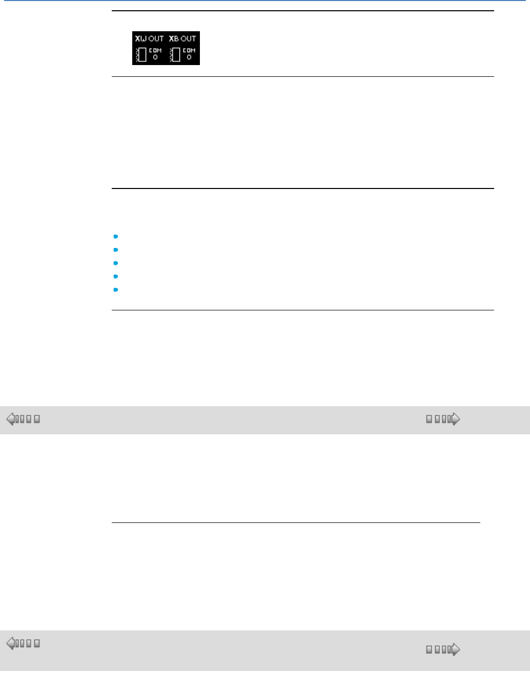
em4 soft Online Help
48
Access
The functions can be accessed from the IN/OUT function bar.
Inputs/Outputs
The function has eight input values (16 bits or 1 bit depending on the FB) called
Value 1 to Value 8. These inputs allow the application programmed in the controller
to send data to the network (COM 0 to COM 3).
COM 0: communication port of the accessory, e.g. Modbus.
COM 1: communication port of extension 1
COM 2: communication port of extension 2
COM 3: communication port of the base card, e.g. 2G, 3G, Ethernet network.
Parameters
The user selects a range of eight addresses from the Parameters window. The
address ranges available are as follows:
XWOUT
26 - 33
XWOUT
34 - 41
XWOUT
42 - 49
XBOUT
50-1
XBOUT
50-2
Parameters file
This file, in XML format, associates a label that can be used by all the network
devices with each data item.
The label is a character string.
1.4.2.3 CTRL functions : control
( § 1.4.2.2.4 )
( § 1.4.2.3.1 )
At a Glance
Subject of this Section
This section describes the different CTRL functions available using FBD
language.
What's in this Section?
This section contains the following topics:
Timer, flip-flop, trigger, comparison, time programmer, slow and high-speed
counter, chronometer, etc.
1.4.2.3.1 TIMERS
( §
1.4.2.3 )
( § 1.4.2.3.2 )
Overview
The TIMERS function block provides access to the following types of timers:
em4 soft Online Help
49
Timer A/C is used to delay or prolong actions over a predetermined time:
Function A: Timer on-delay
Function C: Timer off-delay
Function A-C: Combination of functions A and C
Timer BW is used to create a pulse for the duration of a cycle on the output from an input edge.
Timer Li is used to create flashing (the durations of on and off states can be configured):
Function Li: The flashing cycle starts with an ON state.
Function L: The flashing cycle starts with an OFF state.
Timer B/H creates a pulse on the output of the rising edge of the input.
Function B: Regardless of the duration of the command pulse, the output is active for a duration that
has been set.
Function H: The output is inactive at the end of a set time or on the falling edge of the command.
The totaliser creates a pulse on the output when the period during which the input was active
reaches (one or more times) a set value.
Access
This function block is accessible from the CTRL function bar.
Choice of Timer
To place a timer on the wiring sheet and select its type, proceed as follows:
Step
Action
1
Click on the icon of the FBD function bar, hold down the mouse button and slide the icon to the
required place.
Result: The following window appears:
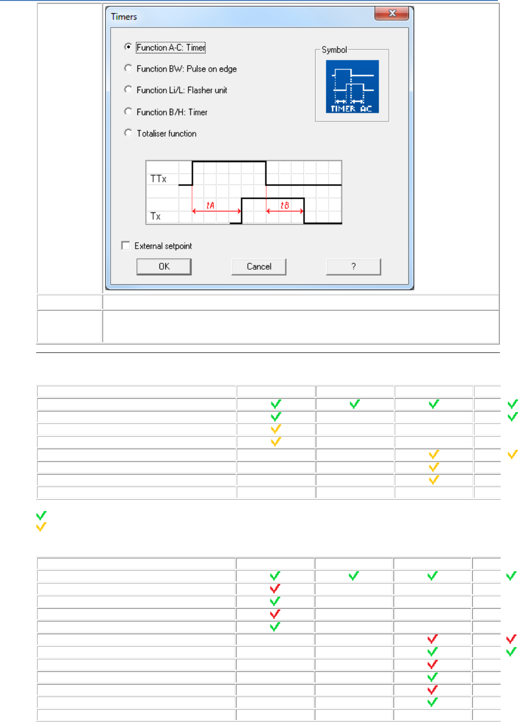
em4 soft Online Help
50
2
Select the desired type of timer from the 5 types available in this window.
3
If required, you can check the External setpoint box: in this case the on time(s) or off time(s) will be integer-type
timer block inputs rather than being internal configurable parameters.
Note: Function unavailable for the timer type BW.
Inputs/Outputs
Timer inputs:
Timer A/C
Timer BW
TIMER Li
Timer B/H
Totaliser
Command
Reset
-
-
On delay setpoint value
-
-
-
-
Off delay setpoint value
-
-
-
-
On setpoint value
-
-
-
Off setpoint value
-
-
-
-
Number/Duration of flashes
-
-
-
-
Total time setpoint value
-
-
-
-
Key:
: Input always available on this timer.
: Input available on this timer only if the External setpoint box was checked when the timer type was
selected.
Timer outputs:
Timer A/C
Timer BW
TIMER Li
Timer B/H
Totaliser
Output
On delay setpoint value
-
-
-
-
On delay current value
-
-
-
-
Off delay setpoint value
-
-
-
-
Off delay current value
-
-
-
-
On setpoint value
-
-
-
On current value
-
-
-
Off setpoint value
-
-
-
-
Off current value
-
-
-
-
Number/Duration of flashes
-
-
-
-
Current value number/duration of flashing
-
-
-
-
Total time setpoint value
-
-
-
-
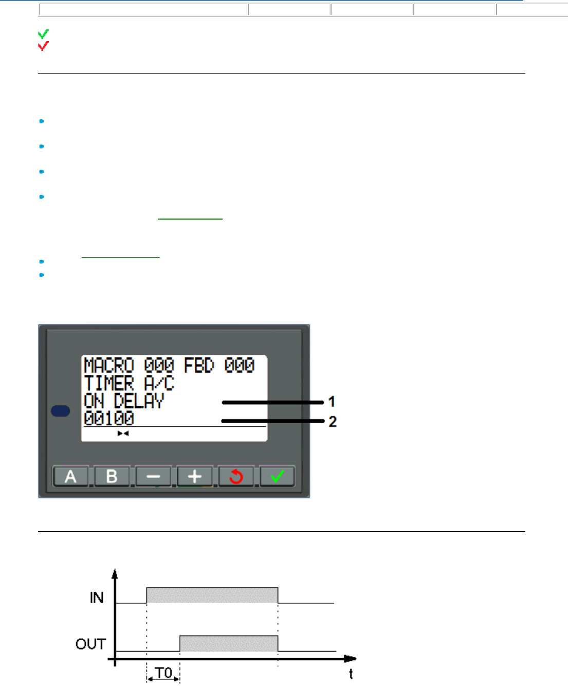
em4 soft Online Help
51
Total time current value
-
-
-
-
Key:
: Output always available on this timer.
: Output available on this timer only if the External setpoint box was left unchecked when the timer
type was selected.
Timer A/C Parameters
In the programming workshop
The Parameters window is used to:
Select the time unit of the delays; these delays can be expressed in seconds (9 hrs 6 min 7 s
maximum = 32,767), tenths of seconds or number of cycles.
Set the ON delay value for function A, only if the External setpoint box was left unchecked when the
timer type was selected.
Set the OFF delay value for function C, only if the External setpoint box was left unchecked when
the timer type was selected.
Possibly activate the Save on power failure parameter. It enables the timer to be restarted at the point
where it stopped after a power failure( § 1.2.20 ).
The combination of both the ON and OFF delays can be used to obtain a function A/C.
From the front panel
From the PARAMETERS( § 1.3.2 ) menu, you can set:
The value of the On delay parameter
The value of the Off delay parameter
To modify the parameters from the controller front panel, check the Modification authorized box in the
Parameters window.
Illustration:
1
Name of the parameter displayed
2
Value of the parameter displayed
Timing Diagrams For Timer A/C
Function A:
T0 : ON Delay.
Function C:
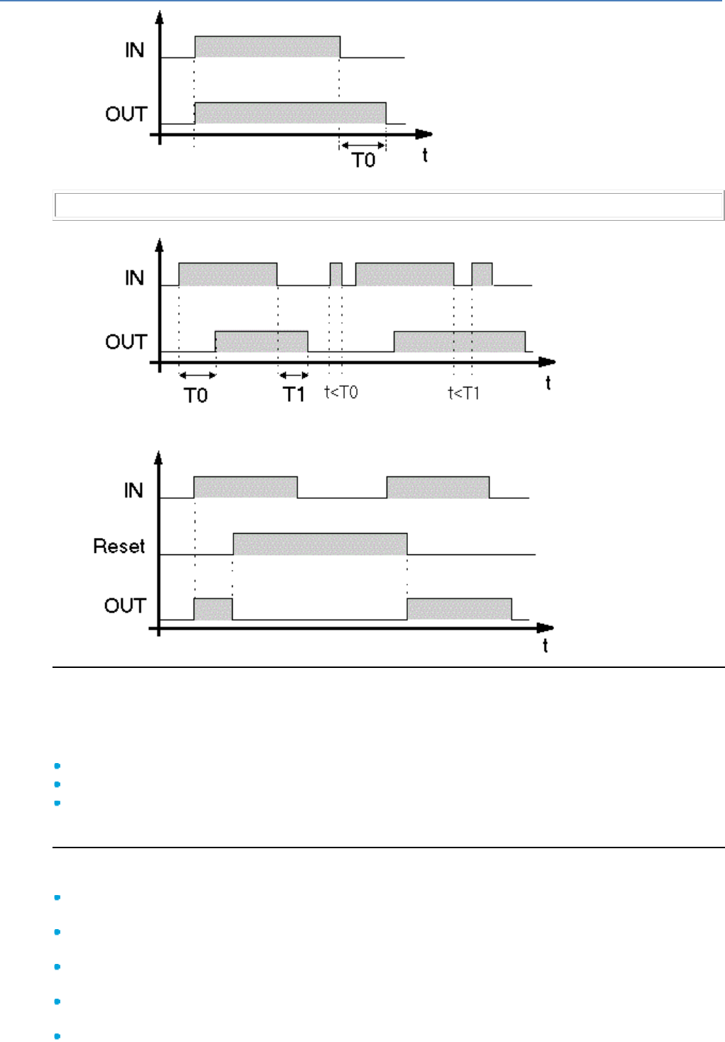
em4 soft Online Help
52
T0 : OFF Delay.
Note: Each pulse on the COMMAND input of the TIMERS timer block resets the current value to 0.
Function A-C:
T0 : ON Delay, T1 : OFF Delay.
Example with reset:
Timer BW Parameters
In the programming workshop
The Parameters window is used to select the type of edge on the input that will generate the pulse on the
output.
Select:
From OFF to ON to generate a pulse on each rising edge of the input
From ON to OFF to generate a pulse on each falling edge of the input
From OFF to ON and from ON to OFF to generate a pulse on each rising edge and each falling edge
of the input
Timer Li Parameters
The Parameters window is used to:
Select the time unit of the delays, these delays can be expressed in seconds (9 hrs 6 min 7 s
maximum = 32,767), tenths of seconds or number of cycles.
Select the type of flashing: select function Li for the flashing to begin with an On state, and select
function L for the flashing to begin with an Off state.
Set the On time value, only if the External setpoint box was left unchecked when the timer type was
selected.
Set the Off time value, only if the External setpoint box was left unchecked when the timer type was
selected.
Select the stop mode of the flashes, select:
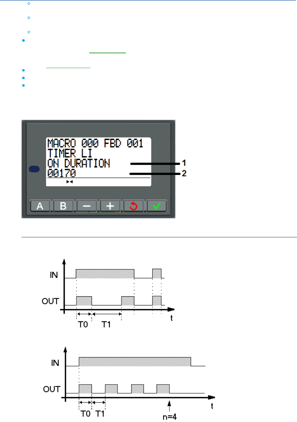
em4 soft Online Help
53
Number of flashes in order to stop after a set number of flashes (enter the value of the number of
flashes, if the External setpoint box was left unchecked when the timer type was selected).
Duration of flashes in order to stop after a set time (enter the value of the duration, if the External
setpoint box was left unchecked when the timer type was selected).
Continuous flashing so that the flashes do not stop until the Command input is active.
Possibly activate the Save on power failure parameter. It enables the timer to be restarted at the point
where it stopped after a power failure( § 1.2.20 ).
From the front panel
From the PARAMETERS( § 1.3.2 ) menu, you can set:
the value of the On time parameter
the value of the Off time parameter
the value of the counting setpoint parameter corresponding either to the duration of flashing, or to the
number of flashes
To modify the parameters from the controller front panel, check the Modification authorized box in the
Parameters window.
Illustration:
1
Name of the parameter displayed
2
Value of the parameter displayed
Timing Diagrams For Timer Li
Continuous flashing mode:
T0 : ON Time, T1 : OFF Time.
Number of flashes mode:
T0 : ON Time, T1 : OFF Time.
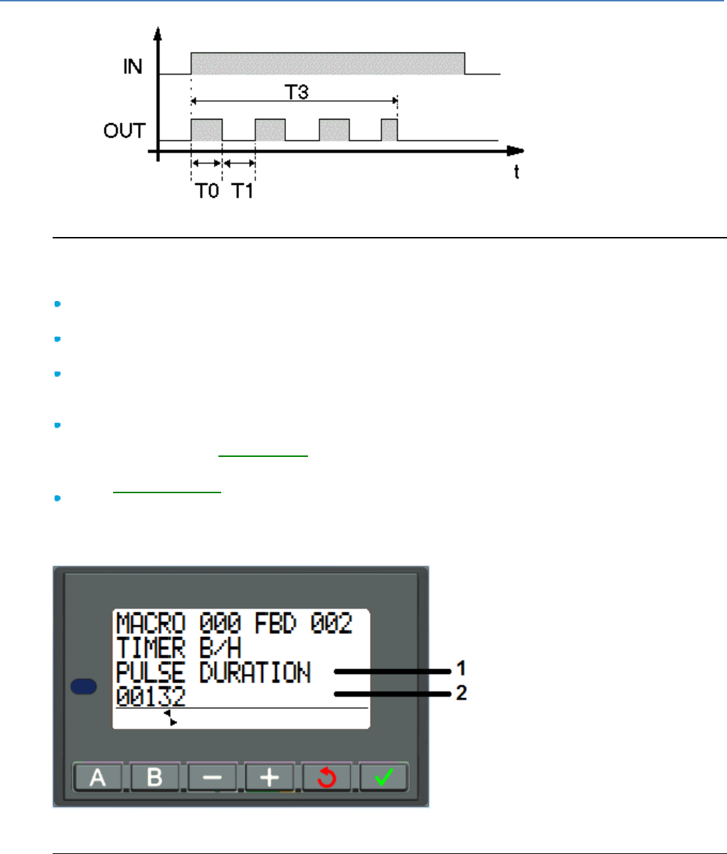
em4 soft Online Help
54
Duration of flashes mode:
T0 : ON Time, T1 : OFF Time, T3 : Flashing period elapsed.
Timer B/H Parameters
In the programming workshop
The Parameters window is used to:
Select the time unit of the ON time; this time can be expressed in seconds (9 hrs 6 min 7 s maximum
= 32,767), tenths of seconds or number of cycles.
Set the On time value, only if the External setpoint box was left unchecked when the timer type was
selected.
Select the operating mode of the timer, select Function B so that the output remains active
regardless of the duration of the command pulse; select Function H so that the output switches to the
inactive state on the falling edge of the command.
Possibly activate the Save on power failure parameter. It enables the timer to be restarted at the point
where it stopped after a power failure( § 1.2.20 ).
From the front panel
From the PARAMETERS( § 1.3.2 ) menu, you can set:
The value of the On time: pulse duration.
To modify the parameters from the controller front panel, check the Modification authorized box in the
Parameters window.
Illustration:
1
Name of the parameter displayed
2
Value of the parameter displayed
Timing Diagrams For Timer B/H
Function B:
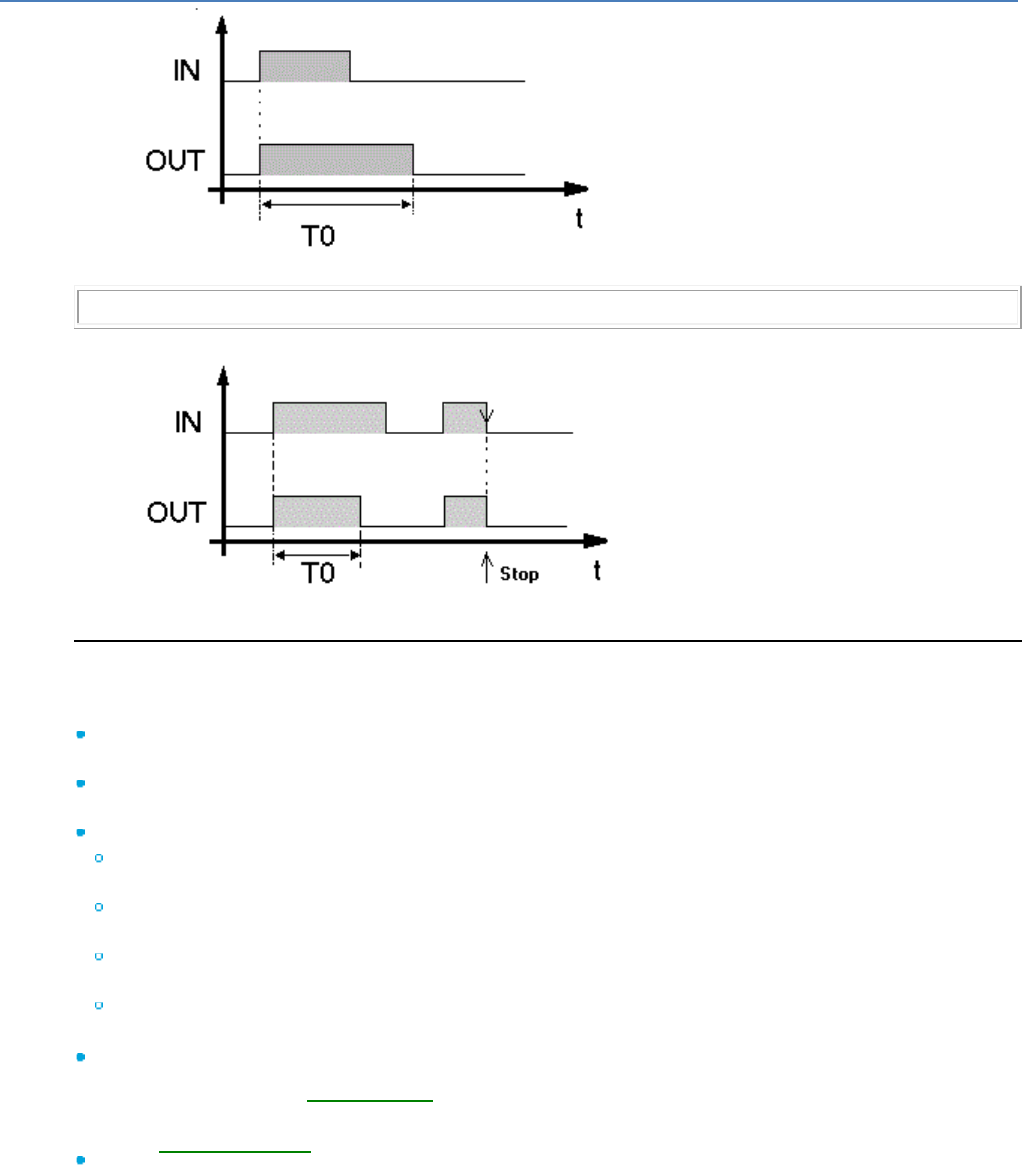
em4 soft Online Help
55
T0 : ON Time.
Note: Each pulse on the timer COMMAND input resets the current value to 0.
Function H:
T0 : ON Time, Stop : Falling Edge of the command input.
Totaliser Parameters
In the programming workshop
The Parameters window is used to:
Select the time unit of the ON time; this time can be expressed in minutes, seconds (9 hrs 6 min 7 s
maximum = 32,767), tenths of seconds or number of cycles.
Set the value T of the time to be reached, only if the External setpoint box was left unchecked when
the timer type was selected
Select the totaliser operating mode , select:
At so that the totaliser output switches to the active state when the time spent in the inactive state by
the input reaches the set time
Ht so that the totaliser output switches to the inactive state when the time spent in the inactive state
by the input reaches the set time
T so that the totaliser output switches to the active state when the time spent in the active state by
the input reaches the set time
Tt so that the totaliser output switches to the active state for a set time when a pulse is detected on
the input
Possibly activate the Save on power failure parameter. It enables the timer to be restarted at the point
where it stopped after a power failure( § 1.2.20 )
From the front panel
From the PARAMETERS( § 1.3.2 ) menu, you can set:
The value of the On time: pulse duration.
To modify the parameters from the controller front panel, check the Modification authorized box in the
Parameters window.
Illustration:
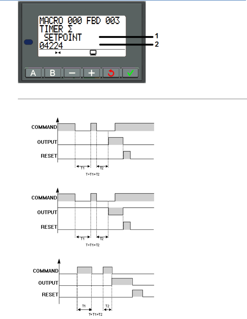
em4 soft Online Help
56
1
Name of the parameter displayed
2
Value of the parameter displayed
Totaliser Timing Diagrams
Function At:
Function Ht:
Function T:
Function Tt:
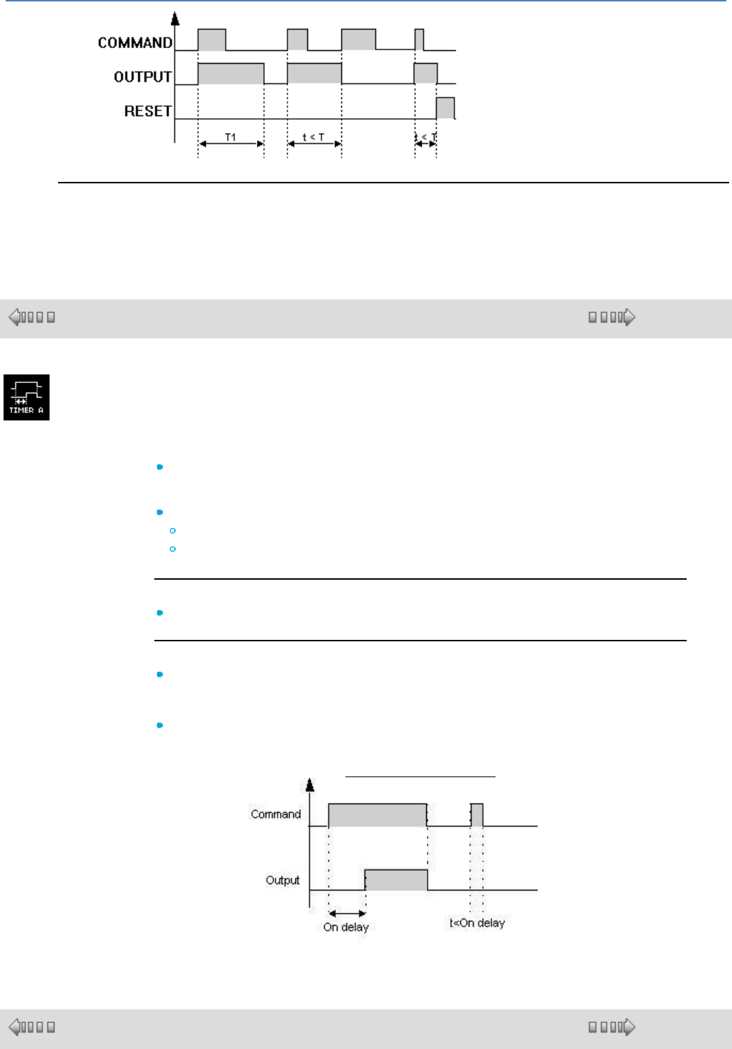
em4 soft Online Help
57
Parameter Modification
To modify the parameters from the controller front panel, check the Modification authorized box in the
Parameters window.
1.4.2.3.2 TIMER A
( § 1.4.2.3.1 )
( § 1.4.2.3.3 )
This function is used to delay actions for a predefined time. This is a simplified
version of TIMER A-C.
FUNCTION A : On-delay
Input:
COMMAND:
When the input is inactive the output is inactive.
When the input is active the output will be active after a predefined time.
Output:
OUTPUT : Value corresponding to the input as defined above.
Parameters:
UNIT : Used to select the time unit for the delays, which can be expressed in
seconds (9 hrs 6 min 7 s maximum = 32,767), tenths of seconds or in number of
cycles.
ON DELAY : Used to set the ON DELAY value for function A.
Timer A timing diagram:
1.4.2.3.3 Bistable Impulse Relay Function
( § 1.4.2.3.2 )
( § 1.4.2.3.4 )
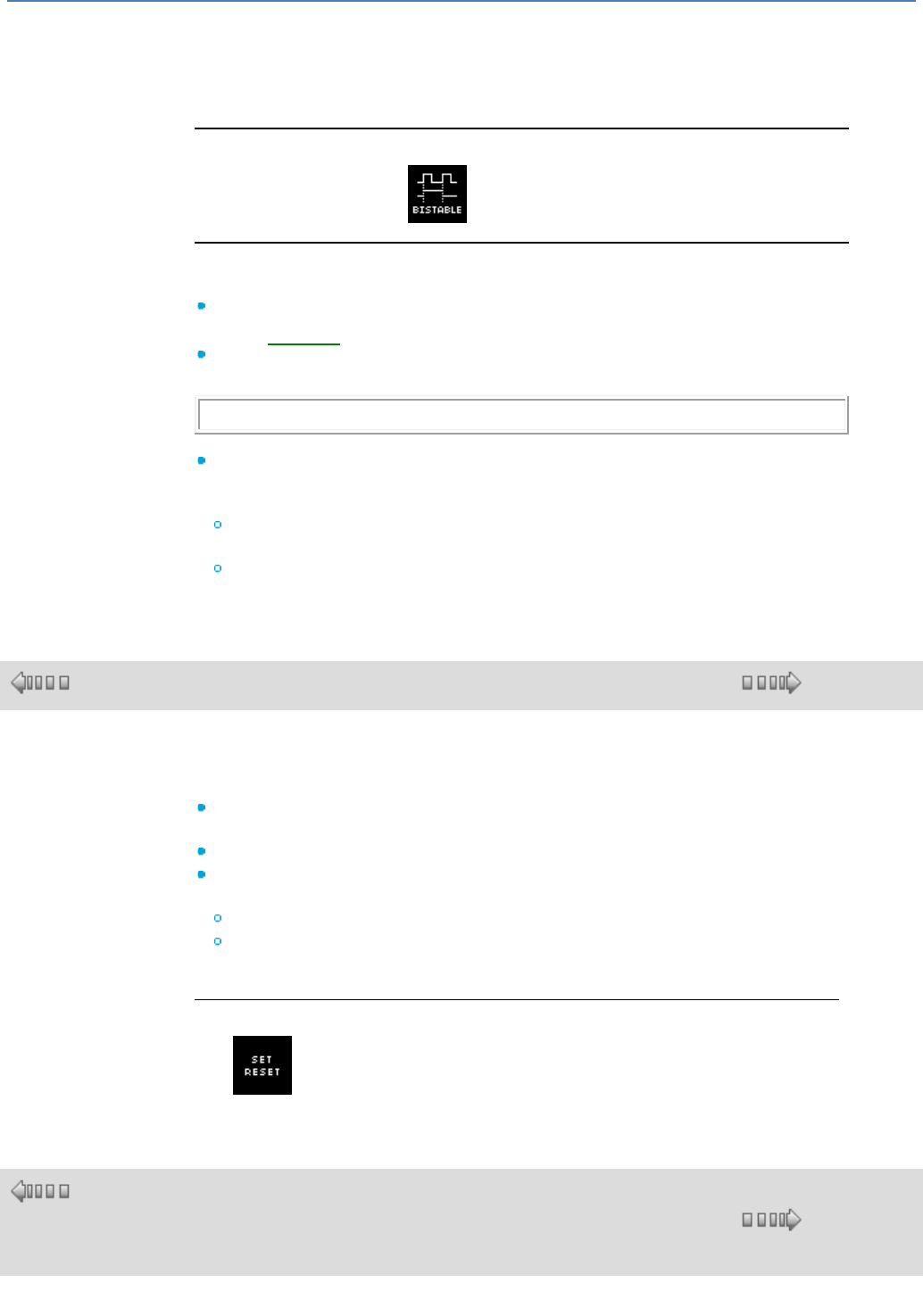
em4 soft Online Help
58
Description
The BISTABLE impulse relay function switches the OUTPUT state on each rising
edge (change from inactive to active) of the COMMAND input.
Access
The impulse relay function is accessible from the CTRL function bar.
Inputs/Outputs
Description of the inputs:
COMMAND: this is the input that controls changes in the output state, whose
type is Discrete( § 1.4.2.1.1 ).
RESET: when this command is active, the OUTPUT always remains inactive,
regardless of the COMMAND input transitions.
Note: If the RESET input is not connected, it is considered to be inactive.
Description of the output:
OUTPUT: this is the impulse relay output, whose type is Discrete.
This value depends upon the state of the RESET input.
If the RESET input is:
Inactive: the OUTPUT changes state in line with the transitions of the
COMMAND input,
Active: the OUTPUT always remains inactive.
1.4.2.3.4 SET and RESET function
( § 1.4.2.3.3 )
( § 1.4.2.3.5 )
At a Glance
The SET RESET function operates as follows:
Activation of the SET input activates the output, which remains so even if the
SET input is then deactivated,
Activation of the RESET input deactivates the output,
If both inputs are active, the state of the output depends on the configuration of
the function:
The output is active if the SET has priority option is configured,
The output is inactive if the RESET has priority option is configured.
Non-connected inputs are set to the Inactive state.
Access
This function is accessible from the CTRL function bar.
1.4.2.3.5 TIMER SET RESET SWITCHING
( §
1.4.2.3.
4 )
( § 1.4.2.3.6 )
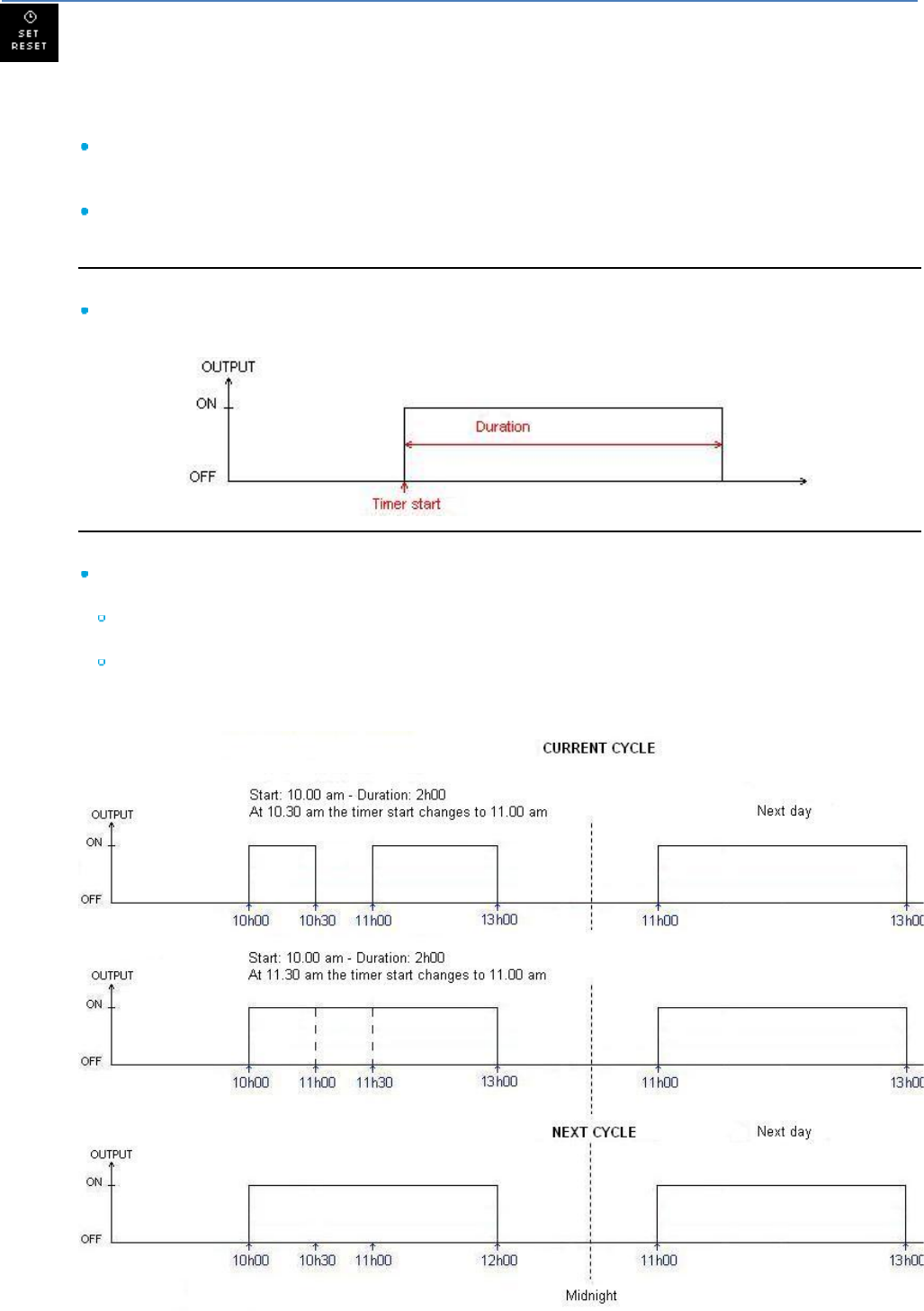
em4 soft Online Help
59
This function is designed to trigger operation of a particular device at a fixed time for a period set by the
user.
Inputs:
TIMER START : Corresponds to the time the output trips, and must comply with the following format:
example for a trip at 09:30, enter 930 on the Timer start input, for 22:45 enter 2245, etc. The value
should never exceed 2359 or 23:59.
DURATION : Corresponds to the period during which the output must be active, and must comply with
the following format: example for a duration of 5 hrs 10 mins, enter 510 on the Duration input.
Output:
OUTPUT : The output is at ON when the value currently on the TIMER START input equals the hour-
minute on the controller for a period equal to the value currently on the DURATION input.
Parameters:
TIME CHANGE : Used to choose the moment at which the time change that occurred as an input is
taken into account when the output is at ON:
CURRENT CYCLE : A change on the TIMER START or DURATION input causes the end time to be
recalculated. These changes are taken into account immediately.
NEXT CYCLE : A change on the TIMER START or DURATION input is not taken into account during
the current cycle, the output remains at ON until the end of the cycle set previously. The new setting
will be taken into account on the next cycle, i.e. when the output changes from ON to OFF.
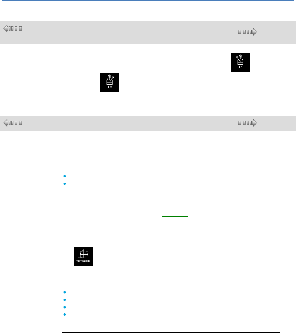
em4 soft Online Help
60
1.4.2.3.6 1 Second Clock
( §
1.4.2.3.5 )
( § 1.4.2.3.7 )
Blinking Input
The blinking input function is active every second. Its active symbol is and its
inactive symbol is .
1.4.2.3.7 Schmitt Trigger
( § 1.4.2.3.6 )
( § 1.4.2.3.8 )
Description
The SCHMITT TRIGGER function allows an analog value to be monitored relative to
two thresholds.
The output changes state if:
The input value is lower than the minimum value
The input value is higher than the maximum value
If the input is between the two, the output does not change state.
Each of the FROM ON TO OFF and FROM OFF TO ON setpoints can just as easily
be the minimum or maximum value. This involves reverse operation of the function.
These two operations are shown in the diagrams( § 1.4.2.3.7 ).
If the ENABLE input is in inactive state, the output remains inactive. The output does
not change state if the ENABLE input changes from Active to Inactive state.
Access
The function is accessible from the CTRL function bar.
Inputs/Outputs
The function uses four inputs:
A VALUE TO COMPARE Integer-type input
An ON TO OFF SETPOINT Integer-type input
An OFF TO ON SETPOINT Integer-type input
An ENABLE FUNCTION Discrete-type input
The function delivers a discrete OUTPUT.
Operating Diagrams
The figure shows the different states that the output can have in the case when the
ON TO OFF SETPOINT is > the OFF TO ON SETPOINT:
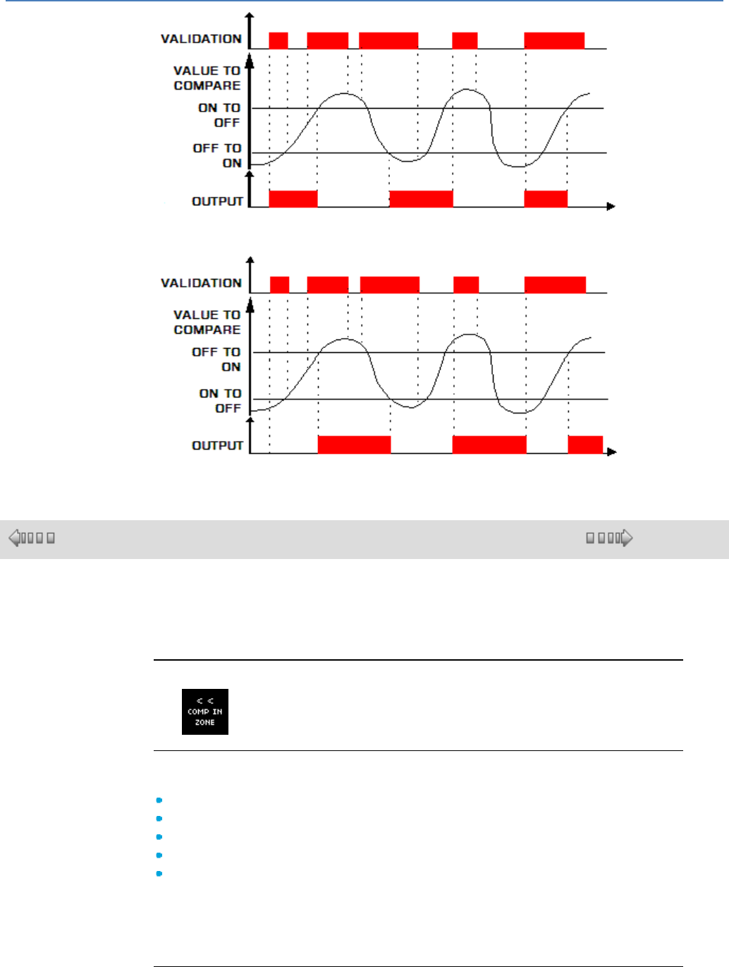
em4 soft Online Help
61
The figure shows the different states that the output can have in the case when the
OFF TO ON SETPOINT is > the ON TO OFF SETPOINT:
1.4.2.3.8 COMP IN ZONE Comparison
( § 1.4.2.3.7 )
( § 1.4.2.3.9 )
Description
The COMP IN ZONE comparison function is used to compare one value between
two setpoints (the MIN and MAX values of the zone).
Access
The function is accessible from the CTRL function bar.
Inputs/Outputs
The comparison function uses:
a discrete ENABLE FUNCTION input; this input is Active if it is not connected,
A VALUE TO COMPARE input whose type is Integer,
A MIN VALUE input, whose type is Integer,
A MAX VALUE input, whose type is Integer,
A discrete OUTPUT.
The OUTPUT indicates the result of the comparison when the ENABLE FUNCTION
input is active.
The OUTPUT does not change state when the ENABLE FUNCTION input is
inactive.
Parameters
From the Parameters window, you can select the state of the output according to
the result of the comparison:
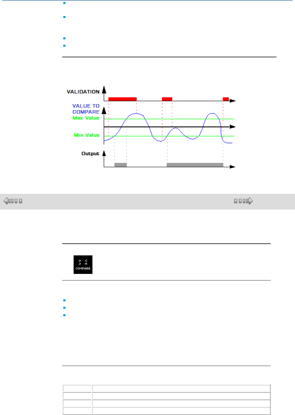
em4 soft Online Help
62
ON in the zone: the output will be active if the input value is between the two
setpoints (MIN and MAX),
OFF in the zone: the output will be inactive if the input value is between the two
setpoints (MIN and MAX).
If MINI is greater than MAXI, then for:
ON in the zone: the output always remains inactive,
OFF in the zone: the output always remains active.
Comparison Function
The diagram below shows the different states the output can take, depending on the
input value to compare and the enable input:
1.4.2.3.9 COMPARE Function for Comparing Two Analog Values
( § 1.4.2.3.8 )
( § 1.4.2.3.10 )
Description
The COMPARE function is used to compare two analog values.
Access
The function is accessible from the CTRL function bar.
Inputs/Outputs
The function uses:
an ENABLE FUNCTION Discrete-type input.
a VALUE 1 Integer-type input,
a VALUE 2 Integer-type input.
If the VALUE 1 or VALUE 2 input is not connected, the value is set to 0.
The function provides a discrete-type OUTPUT.
The output is active if the result of the comparison between VALUE 1 and VALUE
2 is true and if the ENABLE FUNCTION input is active or not connected.
The output does not change state if the ENABLE FUNCTION input changes from
Active to Inactive state.
Parameters
The comparison operators that can be chosen from the Parameters window are:
Symbol
Description
>
Greater than.
Greater than or equal to.
=
Equal to.
em4 soft Online Help
63
Different.
Less than or equal to.
<
Less than.
1.4.2.3.10 MULTICOMPARE Multiple comparison
( § 1.4.2.3.9 )
( § 1.4.2.3.11 )
This function is used to activate the output corresponding to the value present on
the "Value" input.
Inputs:
VALIDATION : Function validation input. Until this input is activated, the function
remains inert. VALIDATION est is active implicitly if it has not been connected.
VALUE : Value to be compared.
Outputs:
VALUE N Output ON if Value = Value N.
VALUE N + 1 : Output ON if Value = Value N + 1.
VALUE N + 2 : Output ON if Value = Value N + 2.
VALUE N + 3 : Output ON if Value = Value N + 3.
VALUE N + 4 : Output ON if Value = Value N + 4.
VALUE N + 5 : Output ON if Value = Value N + 5.
VALUE N + 6 : Output ON if Value = Value N + 6.
VALUE N + 7 : Output ON if Value = Value N + 7.
Operation:
The comparison value (Value N) can be configured. It must be between 0 and
32760.
A : Validation.
B : Value.
C : Value N.
D : Value N+7.
1.4.2.3.11 HL SWITCH Comparison of 5 values
( § 1.4.2.3.10 )
( § 1.4.2.3.12 )
This function compares a value against 5 thresholds.
Inputs:
MEASURED input : value to be compared.
SETPOINT 4 input : threshold value of setpoint 4 if the "External" box on the
parameters page is checked.
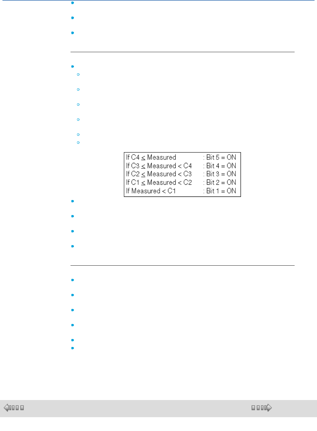
em4 soft Online Help
64
SETPOINT 3 input : threshold value of setpoint 3 if the "External" box on the
parameters page is checked.
SETPOINT 2 input : threshold value of setpoint 2 if the "External" box on the
parameters page is checked.
SETPOINT 1 input : threshold value of setpoint 1 if the "External" box on the
parameters page is checked.
Outputs:
Output bits 1 to 5 of the block correspond to the following equations:
Output Bit 5 is ON if the measured input is greater than or equal to setpoint
4.
Output Bit 4 is ON if the measured input is greater than or equal to setpoint 3
and less than setpoint 4.
Output Bit 3 is ON if the measured input is greater than or equal to setpoint 2
and less than setpoint 3.
Output Bit 2 is ON if the measured input is greater than or equal to setpoint 1
and less than setpoint 2.
Output Bit 1 is ON if the measured input is less than setpoint 1.
The setpoint values must be in the following sequence: C4 > C3 > C2 > C1.
SETPOINT 4 output : threshold value of setpoint 4 if the "External" box on the
parameters page is not checked (can be modified via display).
SETPOINT 3 output : threshold value of setpoint 3 if the "External" box on the
parameters page is not checked (can be modified via display).
SETPOINT 2 output : threshold value of setpoint 2 if the "External" box on the
parameters page is not checked (can be modified via display).
SETPOINT 1 output : threshold value of setpoint 1 if the "External" box on the
parameters page is not checked (can be modified via display).
Parameters:
Setpoint 4 : [3 ; 32767] threshold value of setpoint 4 if the "External" box is not
checked.
Setpoint 3 : [2 ; 32766] threshold value of setpoint 3 if the "External" box is not
checked.
Setpoint 2 : [1 ; 32765] threshold value of setpoint 2 if the "External" box is not
checked.
Setpoint 1 : [0 ; 32764] threshold value of setpoint 1 if the "External" box is not
checked.
External : this box allows you to choose how the setpoint values are adjusted.
Timer : [0 ; 32767] time delay for triggering the output bit.
When the threshold is reached, the time delay starts and at the end of the
period, a new acquisition of the measurement input confirms whether or not the
threshold has been reached.
1.4.2.3.12 Min Max Function
( § 1.4.2.3.11 )
( § 1.4.2.3.13 )
Description
The Min Max function extracts the minimum and the maximum of a signal.
em4 soft Online Help
65
Access
The Min Max function is accessible from the CTRL function bar.
Inputs/Outputs
Description of inputs:
Initialization: Initialization input of the Min Max function, of the Discrete( §
1.4.2.1.1 )-type.
Value: Value of the analog input connected to the Min Max function.
This is an integer between -32.768 and 32.767.
Description of the outputs:
The outputs depend on the state of the INITIALIZATION input.
If the Initialization input is inactive, then:
Minimum is equal to the minimum of the Value input from the last passage
to the inactive state of the initialization input,
Maximum is equal to the maximum of the Value input from the last
passage to the inactive state of the initialization input,
If the Initialization input is ON then the outputs are equal to the Values input.
Note: If the Initialization input is not connected, then it is considered to be
inactive.
1.4.2.3.13 REDUCED AVERAGE Calculating the average value
( § 1.4.2.3.12 )
( § 1.4.2.3.14 )
This function updates the configured average of a number of values by deleting
the minimum and maximum values. The input value is sampled each time the
value changes or every N cycles.
Input:
VALIDATION : Enables the function. If this input is not activated, the function
remains inactive. Activated implicitly if it has not been connected.
INPUT : Sampled value for calculating the reduced average.
Output:
OUTPUT : Reduced average.
Parameters:
NUMBER OF SAMPLES : Number of sampled values for calculating the
average (from 4 to 32767).
SAMPLING : On each change of the value on the ''INPUT'' or every N cycles
(from 1 to 32767).
1.4.2.3.14 TIME PROG Programmer
( § 1.4.2.3.13 )
( § 1.4.2.3.15 )
Description

em4 soft Online Help
66
The TIME PROG daily/weekly/yearly programmer is used to enable the time slots
during which actions can be executed.
This function allows a maximum of 51 events to be defined, which are used to
control its output.
Access
The TIME PROG function is accessible from the CTRL function bar.
Outputs
OUTPUT: this is the programmer validation output.
When one of the cycles that has been set up as a parameter is reached, the
output is active (the output remains active for the entire duration of this cycle.)
Parameters
In the programming workshop
A cycle is defined by:
The type of action: ON or OFF
The time at which it will take effect: Hour/Minute
The activation mode
Cycles can be activated in different ways:
Periodically: Triggering of an event on certain weeks of each month (weekly) or
certain days of the week (daily).
In this case, you will have access to a new set of choices:
Weekly: This choice is enabled by default and all weeks are selected, with
the possibility of selecting only certain weeks.
Daily: This choice is enabled by default and all days are enabled, with the
possibility of selecting only certain days (in which case the Daily option is no
longer valid).
Date: Triggering of a single event on a specific date.
In this case the day, the month and the year should be configured (if necessary,
click on the calendar icon).
Annually: Triggering of an event once a year.
In this case, the month and the day should be configured (if necessary, click on
the calendar icon).
Monthly: Triggering of an event once a month.
In this case, only the day should be configured (if necessary, click on the
calendar icon).
Note: The weeks indicated in Weekly mode do not correspond to calendar
weeks (Monday to Sunday), but are instead defined in relation to the number of
days since the start of the month (the first seven days of the month form the first
week).
Modification from the Front Panel
To modify the parameters from the controller front panel, check the Modification
authorized box in the Parameters window.
From the front panel, only the parameter values can be modified.
It is not possible to:
Add or delete an event
Modify the type (periodic, annual, monthly, and date)
Creating a Cycle
Procedure for creating a new cycle:
Step
Action
1
Create a new cycle by pressing the New button in the Parameters tab.
Result: A new event number appears in the Current cycle box.
em4 soft Online Help
67
2
Configure the time when the event should take place: Hour/Minute.
3
Configure the type of action: ON or OFF.
4
Configure the activation mode according to your criteria (by default, the cycle will be
triggered every day at the time indicated).
5
Confirm by clicking OK.
Result: The new cycle is saved and the parameter setting window is closed.
Modifying a Cycle
Procedure for modifying a cycle:
Step
Action
1
Select the cycle to modify using the Current cycle drop-down menu in the
Parameters tab.
Result: The configuration of the selected cycle is opened.
2
Modify the required parameters.
3
Confirm by clicking OK.
Result: The new cycle is saved and the parameter setting window is closed.
Clearing a Cycle
Procedure for clearing a cycle:
Step
Action
1
Select the cycle to clear using the Current cycle drop-down menu in the Parameters
tab.
Result: The configuration of the selected cycle is opened.
2
Clear the cycle using the Clear button.
Result: The cycle disappears from the drop-down menu.
3
Confirm by clicking OK.
Summary of the Configuration
To take stock of all the cycles created and the conditions that trigger them, simply
select the Summary tab and browse the list of the cycles configured.
The Clear button allows you to delete the designated cycle by clicking in the
Summary tab list.
The Number button allows you to assign a new number (not yet used) to a
designated event by clicking in the Summary tab list.
To modify the characteristics of a cycle, simply double-click on the desired line:
the parameter setting window opens on the selected cycle.
Simulation and Debugging Mode
Clock Configuration
In simulation mode, it is the clock specific to the simulator that is taken into
account. This clock is initialized during the switch to simulation mode with the
time/date of the clock in the PC on which the programming workshop is running.
The clock parameters can be modified subsequently:
Using the Read/Write date and time command on the controller menu
Using the CLOCK command in the MISCELLANEOUS choice, which can be
accessed using the buttons on the front panel
Using the Time Prog Jump Event( § 1.2.7 ) window
Modifying the TIME PROG parameters
These parameters cannot be modified by opening the parameter setting window in
Simulation and Debugging modes.
1.4.2.3.15 WEEK Configurable time programmer
WEEK
( § 1.4.2.3.14 )
( § 1.4.2.3.16 )

em4 soft Online Help
68
The WEEK function is a programmer used to enable the time slots during which
actions can be executed.
This function can define a maximum of 42 events called a "cycle" which are used to
control its "OUTPUT" output.
It is possible to change the parameters which define an event (hour, minute, state)
via the inputs or outputs (using a display unit).
The hours, minutes must be entered in ascending order for each of the days.
Example:
For Monday :
Cycle 0 : ON at 8h00.
Cycle 1 : N.A..
Cycle 2 : OFF at 9h00.
Cycle 3 : ON at 10h00.
etc.
When the cycle value is changed via the "CYCLE" input, the output cycle value
"CYCLE" is refreshed and is the same as the "CYCLE" input, which is not true
when the cycle is changed via the "CYCLE" output; in this case the "CYCLE" input
may differ from the "CYCLE" output. The hour, minute and state output values
displayed are then those corresponding to the value of the "CYCLE" output.
It is not advisable to change the function parameters via the Parameters page in
simulation or debugging mode.
Operation:
Writing via the function inputs:
Changes in the values of the hour, minute, state parameters are only taken
into account on a rising edge of the "NETWORK WRITE" input and if at least
one of the 3 parameters differs from those in memory.
Changes on the cycle input can be used to view the stored values on the
display outputs. It can also be used to identify the cycle(s) which do not
conform to ascending order in the event of an error.
Writing via the function outputs:
Changes in the values of the hour, minute, state parameters are made via a
display; these changes are taken into account when the OK button is pressed,
if the value of the modified parameter differs from that which has been stored.
Changes on the "CYCLE" output can be used to view the stored values on the
display outputs. It can also be used to identify the cycle(s) which do not
conform to ascending order in the event of an error.
Error management:
An error is detected when the day is changed (one day = 6 cycles, Monday ->
cycles 0, 1, 2, 3, 4, 5) if the ascending order of hours and minutes for the day
prior to this change has not been respected. The "ERROR" output is then the
same as the day containing the error (if the error output is 2 then there is an
error on one of the Tuesday cycles, cycles 6, 7, 8, 9, 10 or 11).
If an error is present on the error output, the hour, minute and state
parameters can only be written on cycles where the error is. While the error is
present, it is not possible to change cycle parameters which do not
correspond to the day on the "ERROR" output.
If when changing the day via the input or the cycle output (day containing the
error to another day) ascending order is again detected, the error is corrected
and the error output once again equals 0 which means there is no error. All
the parameters can then be changed again.

em4 soft Online Help
69
Inputs:
VALIDATION : The function is active if the input is ON, and it is ON if not
connected.
NETWORK WRITE : Used to write the hour, minute, state values present as
inputs when a rising edge is detected.
CYCLE Used to select the output values to be displayed (the output values are
refreshed when the value of the "CYCLE" input is changed). Can also be used to
select the cycle for writing the hour, minute and state values present as inputs.
HOUR : Represents the hour to be written when there is a rising edge on the
NETWORK WRITE input in the cycle present as an input.
MINUTE : Represents the minutes to be written when there is a rising edge on
the NETWORK WRITE input in the cycle present as an input.
STATE : Represents the state to be written when there is a rising edge on the
NETWORK WRITE input in the cycle present as an input. 0: OFF, 1: ON, 2: Not
Applicable (N.A.).
OFFSET : Used to time-shift the occurrence of events (in minutes). Example: If
ON at 08.00 and OFFSET= - 120 then the output equals ON at 06.00 instead of
08.00. This input is useful for example with the Heat curve function.
MODE OFF:MODIFS/ON:RUN :
- MODIFS mode can be used to view the hours, minutes, state values of the
Cycle and Cycle+1 corresponding to the value present as an input or as a cycle
output.
- RUN mode can be used to view the hours, minutes, state values corresponding
to the current Cycle and Cycle+1 (in relation to the product time and day).
Note : MODIFS mode can be used to view the hours, minutes, state values of
the Cycle and Cycle+1 corresponding to the value present as an input or as a
cycle output. RUN mode can be used to view the hours, minutes, state values
corresponding to the current Cycle and Cycle+1 (compared to the time and day
on the M3).
Outputs:
OUTPUT : is ON or OFF depending on the events stored and depending on the
date/time on the product.
CYCLE (can be modified via display) : Used to select the output values to be
displayed (the output values are refreshed when the value of the cycle output is
changed). Also used to select the cycle for writing the hour, minute and state
values.
DAY : Corresponds to the day with which the values present on the hour, minute
and status outputs are associated. Monday: 1, Tuesday: 2, Wednesday: 4,
Thursday: 8, Friday: 16, Saturday: 32, Sunday: 64.
HOUR (can be modified via display): Represents the hour to be written when the
OK button on the display connected to it is pressed.
MINUTE (can be modified via display): Represents the minutes to be written
when the OK button on the display connected to it is pressed.
STATE (can be modified via display): Represents the state to be written when
the OK button on the display connected to it is pressed. 0: OFF, 1: ON, 2: Not
Applicable (N.A.)
ERRORS : Represents the day containing the error if the ERROR output is other
than 0. If the ERROR output is 0, there is no error.
FAULT : Is ON if the offset exceeds 255 minutes or if the offset causes an event
trip for the day before the current day.
Parameters:
DAY : Selection of the day for which you wish to modify the cycle values.
HOUR : Hour corresponding to the event trip.
MINUTE : Minute corresponding to the event trip.
STATE: :
OFF : If the event is true (hour and minute on the product is higher or the

em4 soft Online Help
70
same as the hour and minute of the corresponding cycle) then the "OUTPUT"
output changes to OFF.
ON : If the event is true (hour and minute on the product is higher or the same
as the hour and minute of the corresponding cycle) then the "OUTPUT" output
changes to ON.
N.A. : The event is not taken into account.
1.4.2.3.16 PRESET COUNT Up/Down Counter
( §
1.4.2.3.1
5 )
( § 1.4.2.3.17 )
Description
The PRESET COUNT up/down counter function is used to up-count from 0 to the preset value, or to
down-count from this value to 0.
Several functions are available:
Up-counting( § 1.4.2.3.16 ) and forcing the counter to 0 on initialization,
Up-counting( § 1.4.2.3.16 ) and forcing the counter to 0 on initialization and when the count value
has been reached,
Down-counting( § 1.4.2.3.16 ) and forcing the counter to the preset value on initialization,
Down-counting( § 1.4.2.3.16 ) and forcing the counter to the preset value on initialization and when 0
has been reached.
Access
This function is accessible from the CTRL function bar.
Inputs/Outputs
The up/down counter uses:
A discrete UP-COUNT input,
A discrete DOWN-COUNT input,
A discrete INITIALIZATION input.
The up/down counter provides:
A discrete OUTPUT,
The preset value (1),
The current counter value (1),
The output timer value (1).
(1) these integer values are displayed in Simulation and Debugging mode.
Parameters
In the programming workshop
From the Parameters window, you can adjust:
The Upcounting to the preset value or Downcounting from the preset value,
The Preset or Setpoint value (1),
The Single cycle for initializing the counter only on initialization,
The Repetitive cycle for initializing the counter on initialization, and when the current count value
reaches 0 or the preset value.
For the Repetitive cycle, the DURATION OF THE PULSE (x 100ms) corresponding to the time for
which the output is Active.
The Save on power break parameter, if selected, enables the current value of the timer to be retrieved
following a power failure.
From the front panel
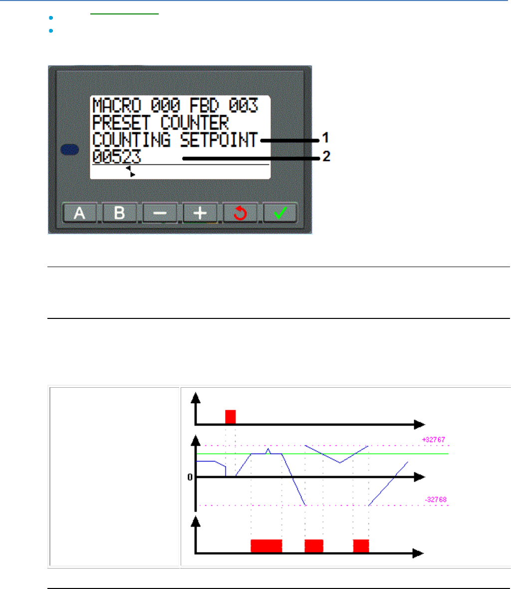
em4 soft Online Help
71
From the PARAMETER( § 1.3.2 ) menu, you can adjust:
The Preset or Counting setpoint value,
The DURATION OF PULSE value (for a repetitive cycle).
Illustration
Illustration: parameters of the counter
1
Name of the parameter displayed
2
Value of the parameter displayed
Parameter Modification
To modify the parameters from the front panel of the controller, check the Authorized modification box
of the Parameters window.
Up-Counting Function in Single Cycle Mode
For the next four graphs, the blue curve represents the internal value of the counter, when it increases
there are pulses at the counting input and when it decreases, at the down-counting input.
The following diagram shows the operation of the counter with initialization at 0:
Initialization
Current counter value
Preset value
Output
Down-Counting Function in Single Cycle Mode
The following diagram shows the operation of the down-counter with initialization at the preset value:
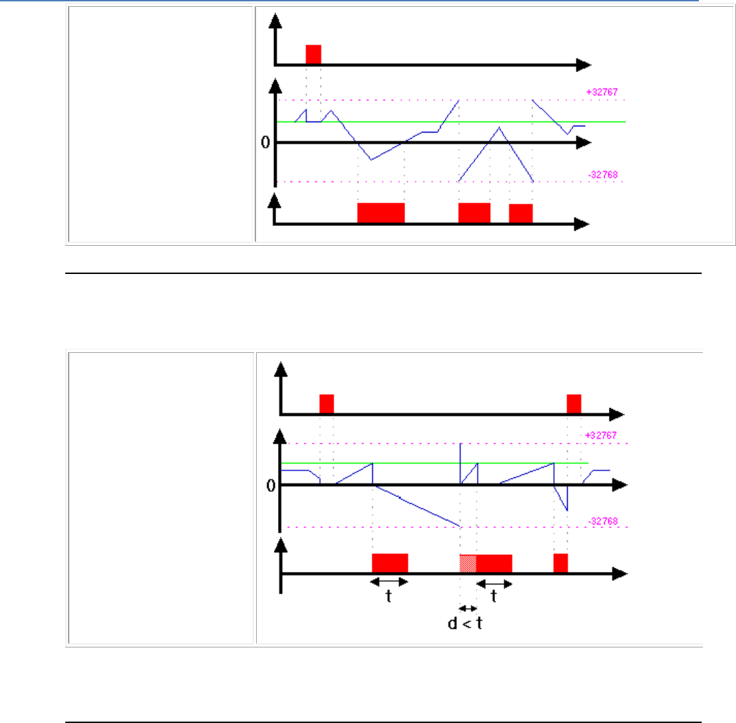
em4 soft Online Help
72
Initialization
Current counter value
Preset value
Output
Up-Counting Function in Repetitive Cycle Mode
The following diagram shows the operation of the counter with forcing to 0 of the current value on
initialization, or when the count value has reached the preset value:
Initialization
Current counter value
Preset value
Output
The output switches to the Inactive state when the predefined pulse duration value has run out. If the
switch condition is Active before the switch to the Inactive state, the output pulse is prolonged by the
DURATION OF THE PULSE (Timing).
Down-Counting Function in Repetitive Cycle Mode
The following diagram shows the operation of the down-counter with forcing to the preset value of the
current value on initialization, or when the count value has reached 0:
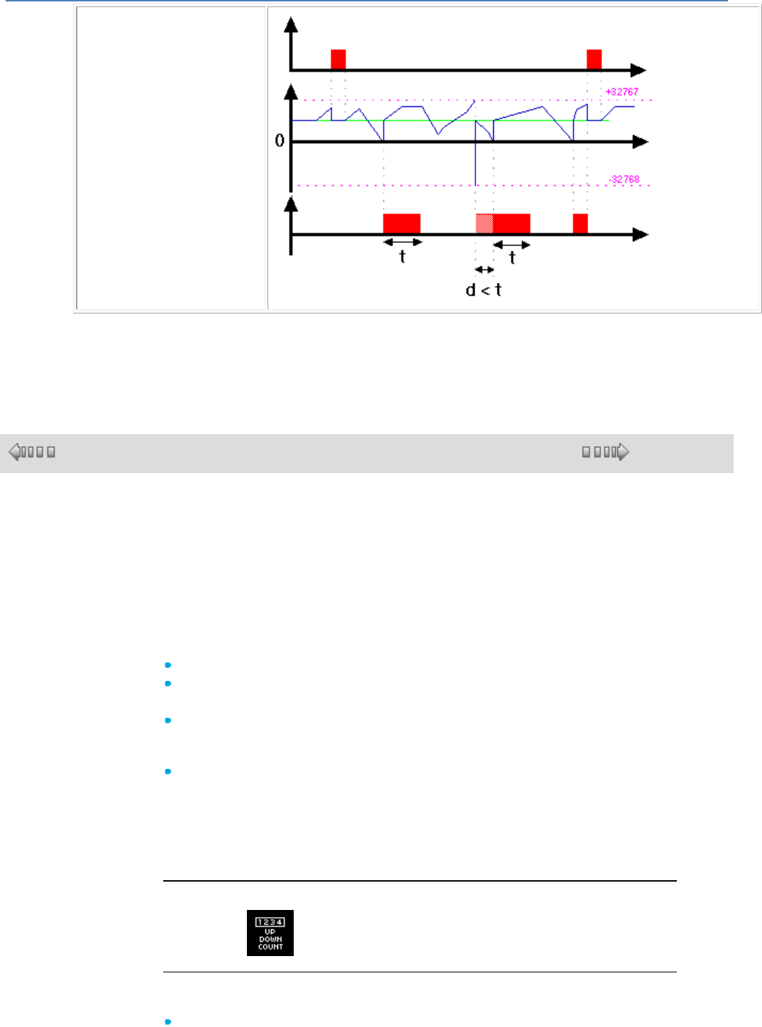
em4 soft Online Help
73
Initialization
Current counter value
Preset value
Output
The output switches to the Inactive state when the predefined pulse duration value has run out. If the
switch condition is Active before the switch to the Inactive state, the output pulse is prolonged by the
DURATION OF THE PULSE (Timing).
1.4.2.3.17 UP/DOWN COUNT Up/Down Counter
( § 1.4.2.3.16 )
( § 1.4.2.3.18 )
Description
The UP/DOWN COUNT function is used to up-count or down-count from a preset
value resulting from a calculation outside the function.
A level 1 on the PRESET FORCING input is used to change the counter with the
value available at the PRESET input.
The PRESET input can be connected to the NUM constant, to an analog input, or
to any other kind of output on a function block which delivers an INTEGER-type
value.
A rising edge on the:
UPCOUNTING: increments the counter.
DOWNCOUNTING: decrements the counter.
State of the OUTPUT:
1: when the counting number has been reached, the OUTPUT switches to 1
and remains so for as long as the counting number is greater than or equal to
the PRESET value,
0: if the transitions on the DOWNCOUNT input switch the counting number
back to a value less than the PRESET value.
Activation of the RESET or PRESET FORCING inputs enable the counter to be
relaunched.
As long as the RESET input is at 1, the OUTPUT remains at 0. When the RESET
input switches to 0, the up/down count operation is relaunched from zero.
Access
This function is accessible from the CTRL function bar.
Inputs/Outputs
The up/down counter uses the following inputs:
UPCOUNTING, Discrete type,
em4 soft Online Help
74
DOWNCOUNT, Discrete type,
RESET, Discrete type,
PRESET FORCING, Discrete type,
PRESET, integer type.
The up/down counter provides the following outputs:
OUTPUT, Discrete type,
CURRENT VALUE, integer type, between -32768 and 32767.
Parameters
The Save on power break parameter, if selected, enables the current value of
the timer to be retrieved following a power failure( § 1.2.20 ).
1.4.2.3.18 PRESET H-METER Preset Hour Counter
( § 1.4.2.3.17 )
( § 1.4.2.3.19 )
Description
The PRESET H-METER hour counter function measures the duration of input
activation. When this duration reaches a preset value, the output is activated.
The duration can be set in hours (Maxi 32767) and minutes.
Activation of the RESET input allows the output to be deactivated and the current
values initialized.
Access
This function is accessible from the CTRL function bar.
Inputs/Outputs
The counter uses:
A discrete COMMAND input,
A discrete RESET input.
If these two inputs are not connected, they are set respectively to Active and
Inactive.
The counter provides:
A discrete OUTPUT,
The copy of the setpoint of the number of hours (1),
The current value of the number of hours (1),
The copy of the setpoint of the number of minutes (1),
The current value of the number of minutes (1),
(1) these integer values are displayed in Simulation and Debugging mode.
Parameters
You can set:
The preset Hour value, which is a value between 0 and 32767,
The preset Minute value, which is a value between 0 and 59.
If the Save on power failure parameter is selected, it enables the timer to be
restarted at the point where it stopped after a power failure( § 1.2.20 ).
Modification from the front panel
To modify the parameters from the front panel of the controller, check the
Authorized modification box of the Parameters window.
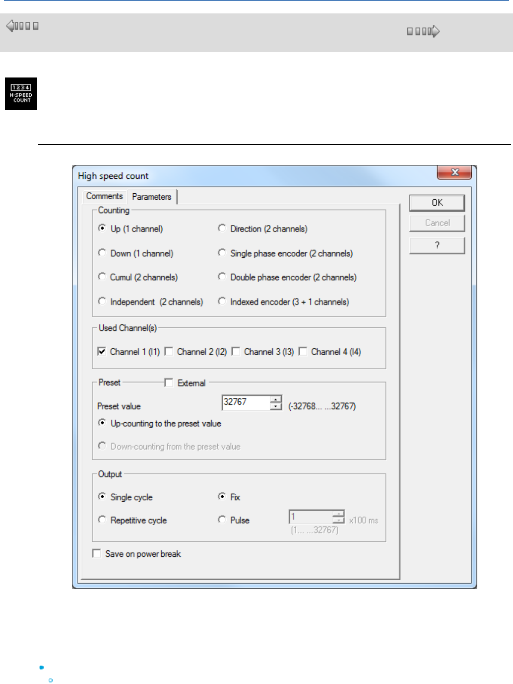
em4 soft Online Help
75
1.4.2.3.19 HIGH SPEED COUNT
( §
1.4.2.3.18 )
( § 1.4.2.3.20 )
This function is used to count the pulses arriving at inputs I1 to I4 of a controller powered by a DC supply, at
rates in excess of one pulse every 2 ms.
How the Graphic Interface Works
The window opens as soon as the block is placed on the edit sheet; there are 5 groups of parameters. The
OK button saves the selected parameters.
The Cancel button cancels changes made since opening the block.
The Backup on power failure box is used to save the parameter table in the event of a power failure.
On first opening the block, the Cancel button, the closing x, and the keyboard shortcut Alt+F4 are
deactivated so that use of channels has to be saved.
Implicit inputs:
Controller inputs I1 to I4 are used for the different types of counting. There is no need to place a
discrete input symbol on the corresponding input plot to confirm use of inputs I1 to I4, nor to make a
connection between the plot and the HIGH SPEED COUNT application-specific function since this link
is implicit. However these plots can still be used in the standard manner, for example to examine the

em4 soft Online Help
76
logical status of the inputs when the counting pulses on the inputs are stopped.
Whether the OFF to ON or ON to OFF edges are taken into account depends on the operating mode
chosen for the counter in the Parameters window.
Explicit inputs:
Activation : Set to 1 if not connected. If the Activation input is at 0, no further counting is done.
Reset : Set to 0 if not connected. If the Reset input is at 1, no further counting is done and the values
are reset.
Preset : Input inactive if the external preset option is not checked. This input is Integer type (-
32768..+32767), and can be used to enter an external Preset value if the box is checked.
This application-specific function has 5 outputs (OUTPUT, ERROR, PRESET VALUE, COUNT/SPEED,
TIME DELAY).
Output : If the counter number has reached the preset value (or 0 in downcounting mode), the output is
set to 1. It remains active depending on whether the output parameter is fixed or pulsed.
Error : Output active when the counter exceeds -32768 or +32767 or when the maximum frequency is
reached. The count is no longer reliable.
Preset value : The internal or external preset is displayed as an output. Value between -32768 and
+32767.
Counter/Speed : This output indicates the current counter value. Value between -32768 and +32767.
Time delay : This output indicates the current value of the time delay in the case of a pulsed output. 0 if
fixed output. Value between +1 and +32767 if pulsed output.
Selecting the Counting Mode.
Only one counting mode can be selected per high-speed counter (exclusive option).
There are 3 different types of counter: 1-channel, 2-channel, and 4-channel counters.
1-channel counting modes are the Up and Down modes. Only one channel is required (I1, I2, I3 or I4).
If Up is selected, the Upcount to preset option is automatically checked and the "Downcount from preset"
option is grayed out and unchecked (in the 'Preset' part).
If Down is selected, the Downcount from preset option is automatically checked and the "Upcount to
preset" option is grayed out and unchecked (in the 'Preset' part).
2-channel counting modes are the Cumul, Independent, Directional, Phase, Phase 2 (double) modes. To
click on one of these modes, it is essential that channel groups I1 & I2 or I3 & I4 are free in the Channel(s)
used zone. Otherwise this mode cannot be chosen (option grayed out).
The 4-channel counting mode is the Indexed counting mode. It is essential that all channels are free if this
mode is chosen. Otherwise this mode cannot be chosen (option grayed out).
Selecting the Channel Used.
A high-speed counter block always uses at least 1 channel. The channels used by the other blocks are
indicated on the parameter-setting sheet: they are grayed out and checked.
If Up or Down mode is selected, choosing 1 available channel will deselect the previously chosen channel.
If Cumul, Independent, Single phase, Double phase or Directional mode is selected, only a pair of
channels can be clicked on: I1 & I2 or I3 & I4. For example, by clicking on I1 or I2, channels I1 and I2 will be
selected. I1 cannot be chosen if I2 is not available, nor I2 if I1 is not available. The same applies to
channels I3 and I4.
If Index mode is selected, all 4 channels are checked and grayed out.
Selecting the Preset.
If External preset is selected, the value of the internal preset can no longer be chosen, and the Preset value
box is grayed out. If External preset is unchecked, the value of the preset can once again be chosen.
The preset value that can be entered is within the range -32768 to +32767.
If Up mode is selected, the "Upcount to preset" option is checked and the "Downcount from preset" option
is unchecked. If Down mode is selected, the "Downcount from preset" option is checked and the "Upcount
to preset" option is unchecked.
For all other mode selections both options are available, but only one at a time.
Selecting the Output.
Two types of output can be chosen: Single shot or Repetitive cycle.
In Single shot either the fixed or pulsed option can be chosen. If Fixed option is activated, the value of the
pulse can no longer be chosen, and the value selection box is grayed out. If Pulsed option is activated, the
value of the pulse can once again be chosen.
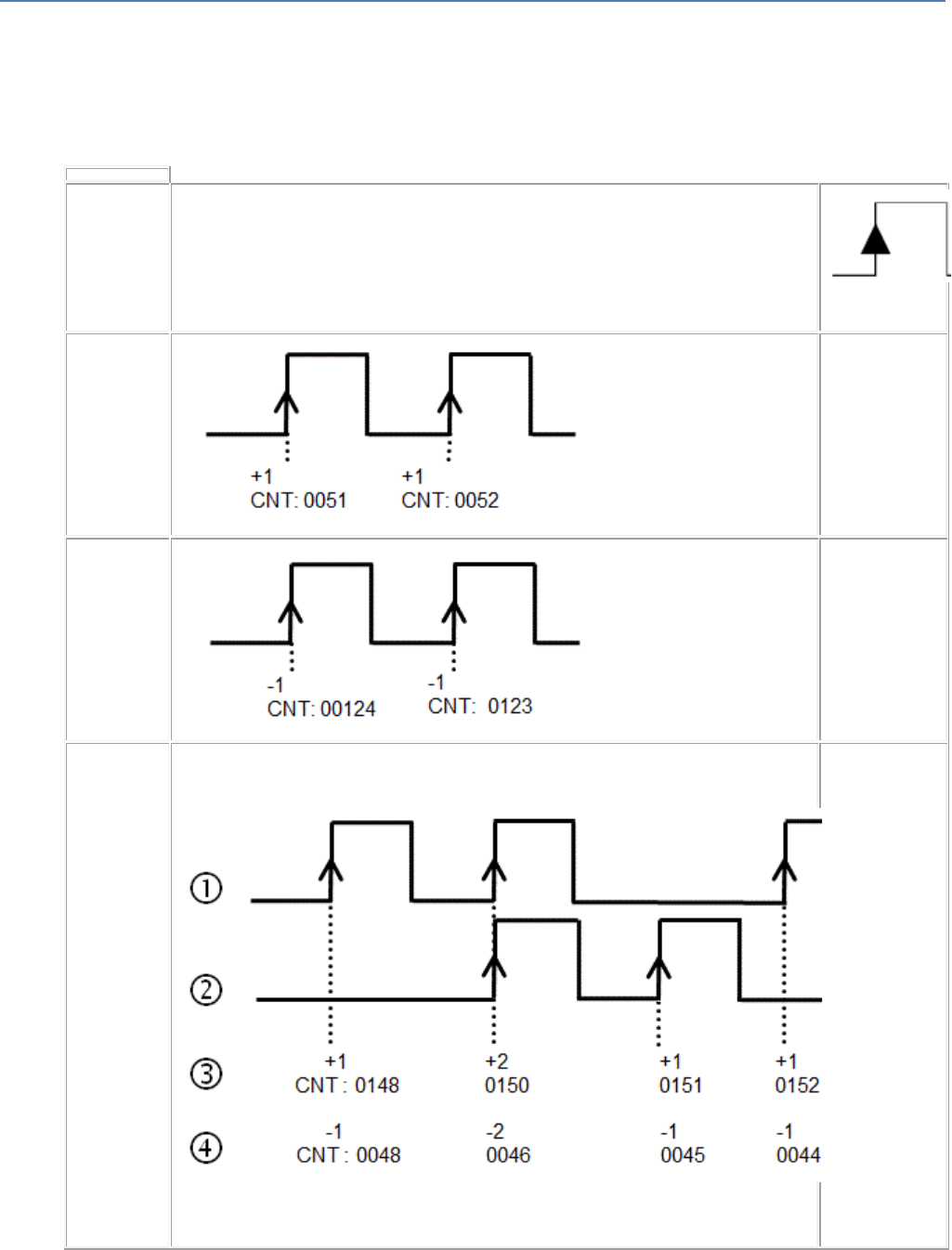
em4 soft Online Help
77
In Repetitive cycle, Fixed option is grayed out and Pulsed option is the only option available. The value of
the pulse can be chosen.
The value of the pulse is between +1 and +32767 (actual pulse = value x 100 ms).
Backup.
The Parameters tab contains the box (which is checked by default) that saves the count after a controller
power failure.
Counting
Modes
Diagrams
Count on
rising edge
UP
The counter
upcounts on
the rising
edge of the
chosen
input (I1, I2,
I3, I4).
DOWN
The counter
downcounts
on the rising
edge of the
chosen input
(I1, I2, I3, I4).
CUMUL
The counter
counts on the
rising edge of
I1 & I2, or I3
& I4.
1 : Input I1 or
I3
2 : Input I2 or
I4
3 : option:
Upcount to
the preset
4 : option:
Downcount
from the
preset
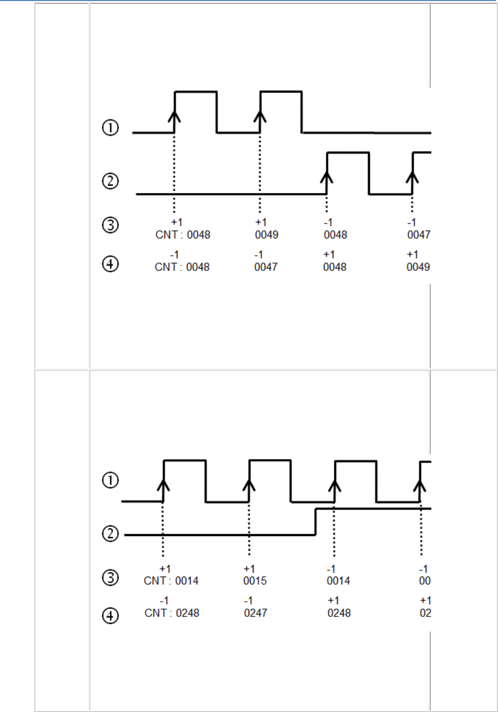
em4 soft Online Help
78
INDEPEN
DENT
The counter
upcounts on
the rising
edge of I1
and
downcounts
on the rising
edge of I2, or
upcounts on
the rising
edge of I3
and
downcounts
on the rising
edge of I4.
1 : Input I1 or
I3
2 : Input I2 or
I4
3 : option:
Upcount to
the preset
4 : option:
Downcount
from the
preset
DIRECTIO
NAL
The counter
upcounts on
channel I1,
direction of
counting
reversed
according to
the state of
input I2.
or
The counter
upcounts on
channel I3,
direction of
counting
reversed
according to
the state of
input I4.
1 : Input I1:
counting in
the direction
of the cycle
2 : Input I2:
direction of
counting
reversed
3 : COUNT
output,
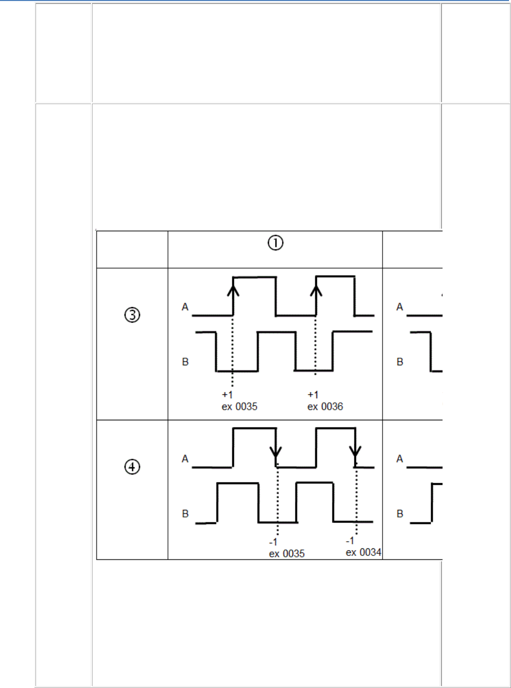
em4 soft Online Help
79
Upcount to
the preset
option
4 : COUNT
output,
Downcount
from the
preset option
PHASE
The counter
is
incremented
on each
rising edge of
I1 when the
phase-shift
between I1
and I2 is
+90° (+pi/2)
and is
decremented
on each
falling edge
of I1 when
the phase-
shift between
I1 and I2 is –
90° (-pi/2). Or
the counter is
incremented
on each
rising edge of
I3 when the
phase-shift
between I3
and I4 is
+90° (+pi/2)
and is
decremented
on each
falling edge
of I3 when
the phase-
shift between
I3 and I4 is –
90° (-pi/2).
1 : Upcount
to preset
2 :
Downcount
from preset
3 :
UPCOUNT
direction
4 :
DOWNCOUN
T direction
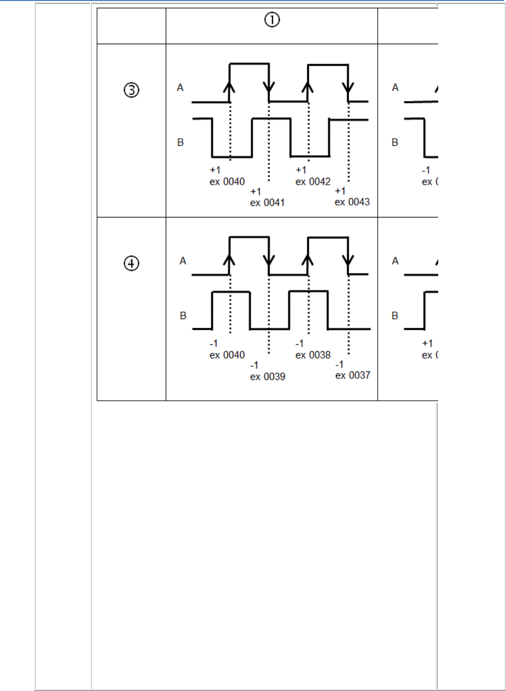
em4 soft Online Help
80
PHASE 2:
Double
phase
The counter
is
incremented
on each edge
(rising or
falling) of I1
when the
phase-shift
between I1
and I2 is
+90° (+pi/2)
and is
decremented
on each edge
(rising or
falling) of I1
when the
phase-shift
between I1
and I2 is -90°
(-pi/2).
Or
The counter
is
incremented
on each edge
(rising or
falling) of I3
when the
phase-shift
between I3
and I4 is
+90° (+pi/2)
and is
decremented
on each edge
(rising or
falling) of I3
when the
phase-shift
between I3
and I4 is -90°
(-pi/2).
1) Upcount to
preset
2)
Downcount
from preset
3) UPCOUNT
direction
4)
DOWNCOUN
T direction
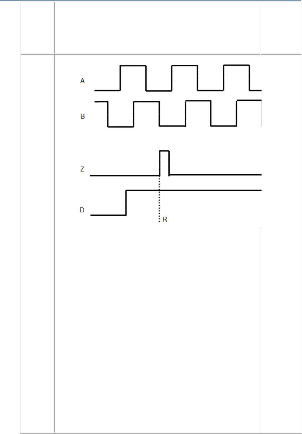
em4 soft Online Help
81
A: Channel A
B: Channel B
INDEX
The counter
is
incremented
on each
rising edge of
I1 when the
phase-shift
between I1
and I2 is
+90° (+pi/2)
and is
decremented
on each
falling edge
of I1 when
the phase-
shift between
I1 and I2 is -
90° (-pi/2).
Operation is
identical to
the Phase
mode with an
additional
channel Z. A
pulse
appears on
this channel
on each
encoder
revolution,
which
determines a
reference
position. This
pulse usually
lasts for 90°
electrical.
A: Channel A
B: Channel B
Z: Index
R:
Mechanical
reset to the
pre-
introduction
value
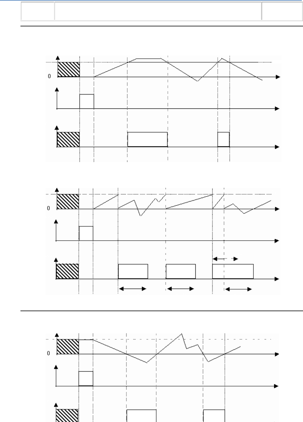
em4 soft Online Help
82
Upcount to preset mode
Single shot : The output is fixed or pulsed
The pulse is adjustable in 100 ms intervals from +1 to +32767
Counte
r
Reset
Output
Prese
t
Repetitive cycle : The output is pulsed
The pulse is adjustable in 100 ms intervals from +1 to +32767
Counter
Reset
Output
Preset
Time Delay Time Delay Time Delay
Downcount from preset mode
Single shot
Counter
Reset
Output
Preset
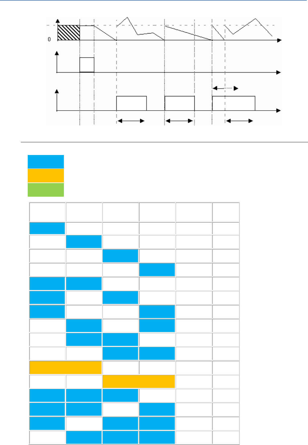
em4 soft Online Help
83
Repetitive cycle
Counter
Reset
Output
Preset
Time Delay Time Delay Time Delay
Possible Combinations
1-channel counter
2-channel counter
4-channel counter
I1
I2
I3
I4
Frequency
Counter
total
60kHz
1
60kHz
1
60kHz
1
60kHz
1
40kHz
2
40kHz
2
40kHz
2
40kHz
2
40kHz
2
40kHz
2
40kHz
1
40kHz
1
30kHz
3
30kHz
3
30kHz
3
30kHz
3
em4 soft Online Help
84
30kHz
2
30kHz
2
30kHz
2
30kHz
2
20kHz
4
20kHz
2
20kHz
1
CAUTION
If the frequency is exceeded, at first there is a loss of pulses.
If there is further increases of frequency, the WATCHDOG triggered and there is a reset
of the product.
Failure to follow these instructions can result in injury or equipment damage.
1.4.2.3.20 Tachometer, Chronometer, Period meter
( §
1.4.2.3.19 )
( § 1.4.2.4 )
This function is used to count the time or the frequency between pulses arriving at inputs I1 to I4 of a
controller powered by a DC supply, at rates in excess of one pulse every 2 ms.
How the Graphic Interface Works
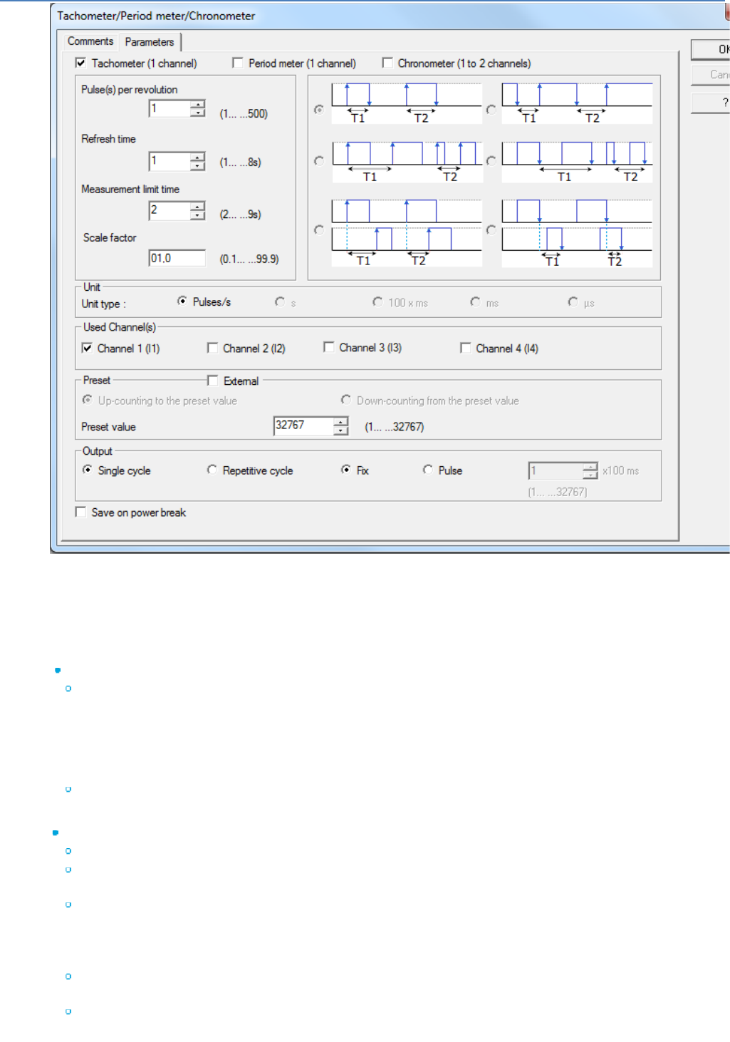
em4 soft Online Help
85
The window opens as soon as the block is placed on the edit sheet, there are 5 groups of parameters. The
OK button saves the selected parameters.
The Cancel button cancels changes made since opening the block.
The Backup on power failure box is used to save the parameter table in the event of a power failure.
On first opening the block, the Cancel button, the closing x, and the keyboard shortcut Alt+F4 are
deactivated so that use of channels has to be saved.
Implicit inputs:
Controller inputs I1 to I4 are used for the different types of counting. There is no need to place a
discrete input symbol on the corresponding input plot to confirm use of inputs I1 to I4, nor to make a
connection between the plot and the TACHOMETER/PERIOD METER/CHRONOMETER application-
specific function since this link is implicit. However these plots can still be used in the standard
manner, for example to examine the logical status of the inputs when the counting pulses on the inputs
are stopped.
Whether the OFF to ON or ON to OFF edges are taken into account depends on the operating mode
chosen in the Parameters window.
Explicit inputs:
Activation : Set to 1 if not connected. If the Activation input is at 0, no further calculations are made.
Reset : Set to 0 if not connected. If the Reset input is at 1, no further calculations are made and the
values are reset.
Preset : Input inactive if the external preset option is not checked. This input is Integer type (-
32768..+32767), and can be used to enter an external Preset value if the box is checked.
This application-specific function has 5 outputs (OUTPUT, ERROR, PRESET VALUE, COUNT/SPEED,
TIME DELAY).
Output : If the counter number has reached the preset value (or 0 in downcounting mode), the output
is set to 1. It remains active depending on whether the output parameter is fixed or pulsed.
Error : Output active when the counter exceeds -32768 or +32767 or when the maximum frequency is
reached. The calculation is no longer reliable.

em4 soft Online Help
86
Preset value : The internal or external preset is displayed as an output. Value between -32768 and
+32767.
Counter/Speed : This output indicates the current counter value. Value between -32768 and +32767.
Time delay : This output indicates the current value of the time delay in the case of a pulsed output. 0
if fixed output. Value between +1 and +32767 if pulsed output.
Selecting the Mode.
Only one mode can be selected of the 3 available: Tachometer, Period meter, Chronometer.
Tachometer mode uses one channel (I1, I2, I3 or I4). On clicking on Tachometer mode, the Cycle
parameters can be set in turn (range +1 to +500), Refresh period (range +1 to +8 s), Measurement limit
period (range +2 to +9 s), and Scale factor (range between +0.01 and 99.9). It is not possible to choose a
unit.
The Period meter mode uses one channel (I1, I2, I3 or I4). On clicking on Period meter mode, the Cycle
parameters can be set in turn (range +1 to +500), Refresh period (range +1 to +8 s), Measurement limit
period (range +2 to +9 s), and Scale factor (range between +0.01 and 99.9). The unit can be set and there
is a choice between "100 x ms", "ms" and "µs".
Chronometer mode uses one channel (I1, I2, I3 or I4) or two channels (I1 & I2 or I3 & I4). On clicking on
Chronometer mode, a choice is offered between the different chronometer modes defined by the timing
diagrams. A two-channel timing diagram represents a timing diagram using two channels. The unit can be
set and there is a choice between "s" and "100 x ms". The preset direction can be chosen and the "Upcount
to preset" and the "Downcount from preset" options in the Preset group are available.
Selecting the Unit.
If Tachometer mode is selected, there is no choice, only "pulse/s".
If Period meter mode is selected, there is a choice between "100 x ms", "ms" and "µs".
If Chronometer mode is selected, there is a choice between "s" and "100 x ms".
Selecting the Channel Used.
A tachometer/period meter/chronometer block always uses at least 1 channel. Channels used by the other
blocks are indicated on the parameter-setting sheet: they are grayed out and checked.
If 1-channel Tachometer, Period meter or Chronometer mode is selected, clicking on 1 available channel
will deselect the previously selected channel and will select the new channel.
If 2-channel Chronometer mode is selected, this can only use a pair of channels: I1 I2 or I3 I4. For
example, by clicking on I1 or I2, channels I1 and I2 will be selected. I1 cannot be chosen if I2 is not
available, nor I2 if I1 is not available. The same applies to channels I3 and I4.
Selecting the Preset
If external preset is checked, the value of the internal preset can no longer be chosen, and the value
selection box is grayed out. If external preset is unchecked, the value of the preset can once again be
chosen.
The preset value that can be entered is within the range +1 to +32767.
In Tachometer and Period meter mode, the "Upcount to preset" and "Downcount from preset" options
cannot be chosen. Only one of the two Chronometer mode options can be chosen.
Selecting the Output
Two types of output can be chosen: single shot or repetitive cycle.
In single shot either the fixed or pulsed option can be chosen. If fixed option is activated, the value of the
pulse can no longer be chosen, and the value selection box is grayed out. If pulsed option is activated, the
value of the pulse can once again be chosen.
In repetitive cycle, fixed option is grayed out and pulsed option is the only option available. The value of the
pulse can be chosen.
The value of the pulse is between +1 and +32767 (actual pulse = value x 100 ms).
Backup.
The Parameters tab contains the box (which is checked by default) that saves the count after a controller
power failure.
Tachometer Mode.
The tachometer operates in two stages:
Triggering the measurement validation phase
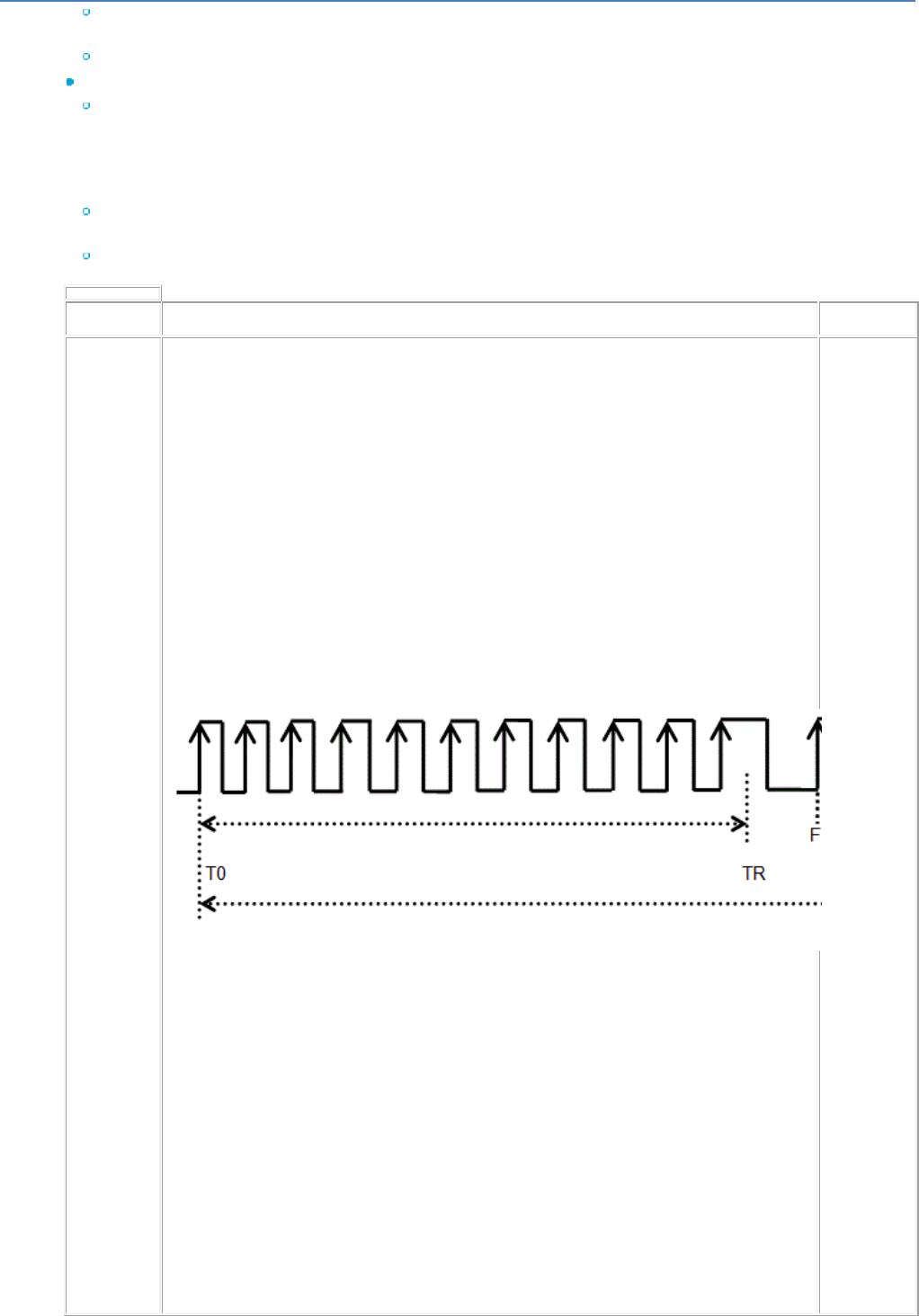
em4 soft Online Help
87
As soon as a rising edge appears on the input, the function scans the input during a period T0-TL.
When a new rising edge appears on the input, the measurement limit phase gets under way.
If this is not the case, no measurement occurs.
Triggering the Measurement Phase
From the previous rising edge, the function scans the input during the Measurement limit phase (from
T0 to TL).
If rising edges appear on the input during the Refresh period, as soon as the first rising edge (F1 )
appears between TR and TL, the speed is calculated as follows and the system reverts to the
measurement validation phase on the next rising edge (F2) that appears on the input.
Pulses per revolution : This is the number of pulses (rising edges) corresponding to one encoder
revolution, one tachometer wheel revolution, etc.
Scale Factor : This is a multiplication coefficient.
Diagrams
Triggerin
g the
Measure
ment
Phase
T0:
Tachomet
er
measure
ment start
time
F1: First
rising
edge after
TR
TR - T0:
Refresh
period.
Minimum
period
after
which end
of
measure
ment can
be
acknowle
dged.
TL - T0:
Measure
ment limit
period.
Maximum
period
after
which end
of
measure
ment
should
have been
achieved.
(If this
period is
reached
without a
pulse
appearing
on the
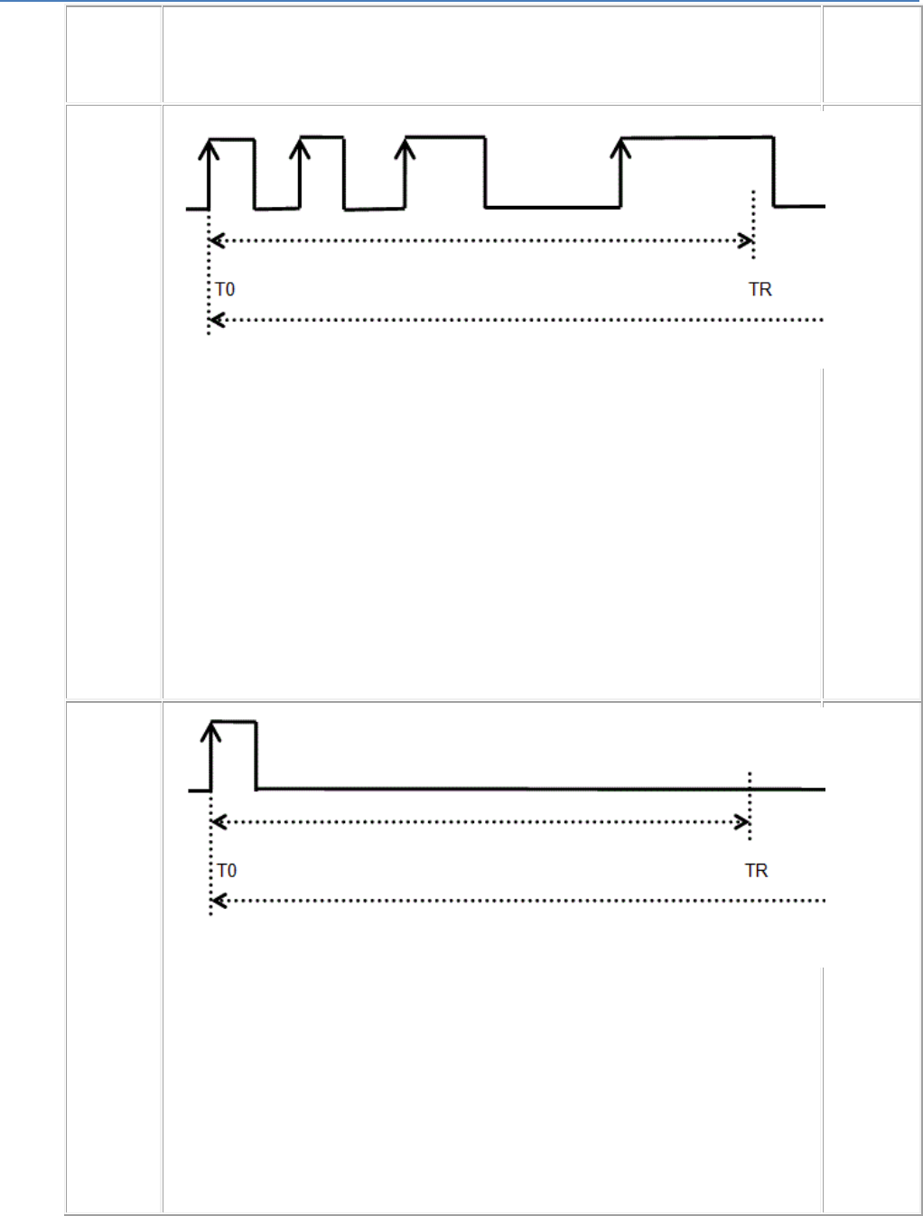
em4 soft Online Help
88
input, the
speed is
zero)
If during
the
refresh
period
(from T0
to TR)
more than
one rising
edge
appear on
the input,
but none
in the
period TR
to TL, the
calculated
speed is
zero and
the
system
returns to
the
validation
phase
after the
second
period has
elapsed.
If during
the whole
of this
period
(from T0
to TR)
only one
rising
edge
appears
on the
input, the
calculated
speed is
zero and
the
system
returns to
the
validation
phase
after the
period has
elapsed.
Calculating the Speed:
Calculation occurs without loss of accuracy, irrespective of the parameters. However this implies that the
number of pulses counted in tachometer function during a measurement period must not exceed ≈ 43000.
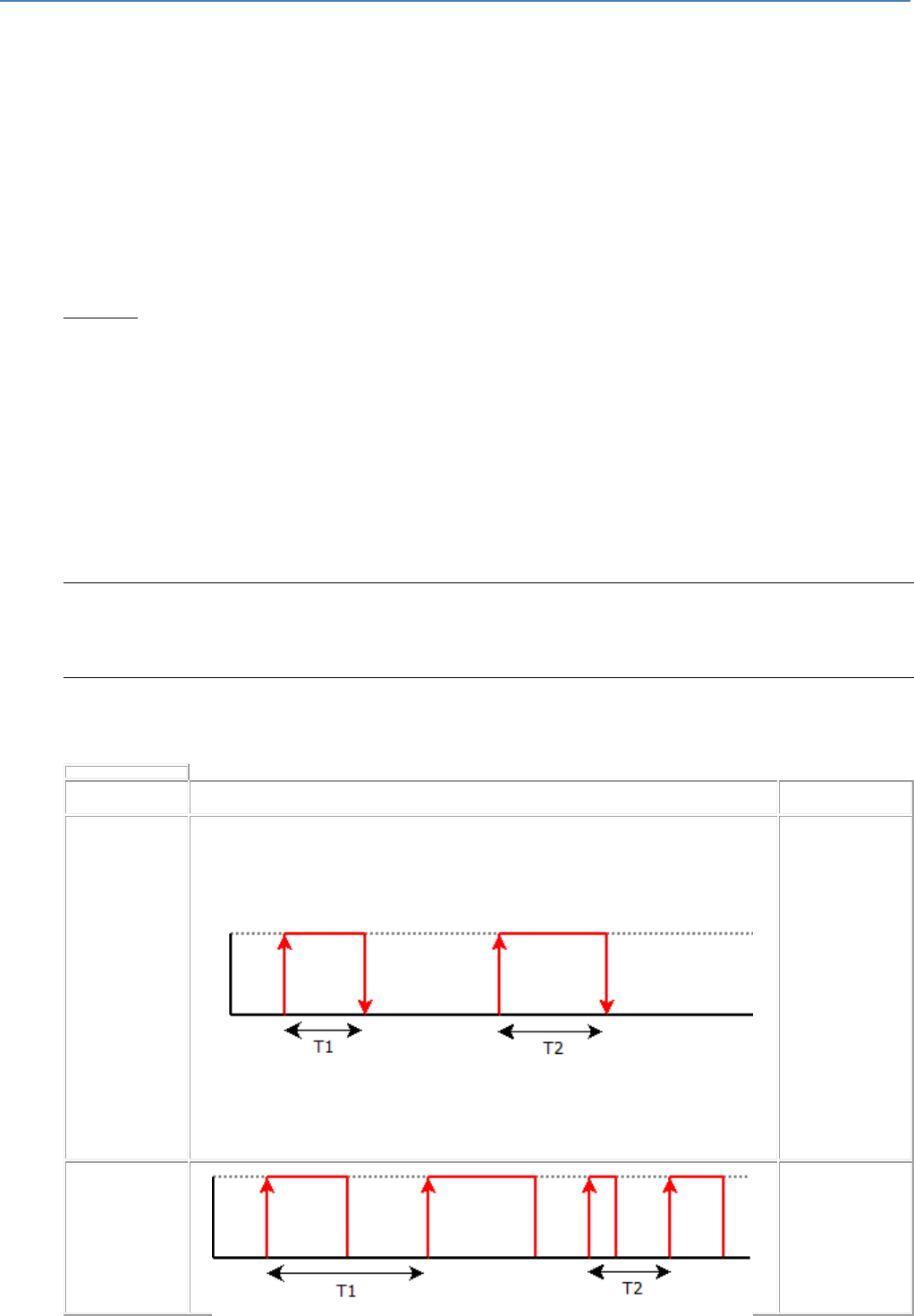
em4 soft Online Help
89
N: Number of pulses recorded during the measurement phase.
NPPS : Number of Pulses Per Second : number of pulses per second
PPr : Pulses Per revolution : pulses per revolution
Coeff : Multiplication coefficient (value of "Scale factor" parameter)
TM : Measurement period (in seconds)
NPPS=N/TM
v : speed or its equivalent of the measured process. The measurement unit is arbitrary and corresponds to
the application's needs: m/s, no. of objects per second, etc.
v = (NPPS * Coeff) / PPr
As the calculated value of the speed must be less than or equal to 32767, the number of pulses per second
can be, at the most, equal to the maximum NPPS = (32767 * PPr)/Coeff with "Max. NPPS" less than or
equal to 32767.
Example:
The speed of conveyor belt is measured using a roller connected to a tachometer wheel. The roller runs
over 5 cm of . The wheel gives 10 pulses per revolution. We wish to find the belt travel speed in cm/s.
The belt travels by * = 15.7 cm per roller revolution.
The Cycle(s) per revolution is therefore fixed at 10 and Scale factor at 15.7.
The belt travels on average 50 cm/s, resulting in N = NPPS* TM = v*PPr/Coeff* TM, or<
N = 50*10/15,7* TM = 31* TM
In the chosen application the conveyor belt is permanently running and has a quasi-constant speed. A long
refresh period can therefore be chosen which can increase accuracy, for example 8 s and 9 s for the
measurement limit period.
In our example N = 31*9 = 279, which is well below 32,767 and therefore leaves a large margin for error.
Period Meter Mode.
The period is calculated on the basis of the tachometer parameters. It is the average time between each
pulse during the measurement period.
Chronometer Mode.
Depending on the chosen mode, 4 or 2 independent chronometers can be obtained:
Diagrams
4
independent
chronometers
Start
:
On rising
edge
Stop :
On falling
edge
Input I1, I2, I3
or I4
4
independent
chronometers
Start / stop
:
Input I1, I2, I3
or I4
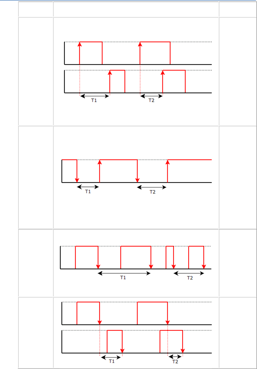
em4 soft Online Help
90
On Rising
edge
2
independent
chronometers
Start
:
On Rising
edge of one
channel
Stop
:
On Rising
edge of the
other channel
A: input I1 or
I3
B: input I2 or
I4
Caution: 2
edges on
channel A
cause a return
to the previous
counter value.
4
independent
chronometers
Start
:
On falling
edge
Stop
:
On rising
edge
Input I1, I2, I3
or I4
4
independent
chronometers
Start / stop
:
On Falling
edge
Input I1, I2, I3
or I4
2
independent
chronometers
Start
:
On Falling
edge of one
channel
A: input I1 or
I3
B: input I2 or
I4
Caution: 2
edges on
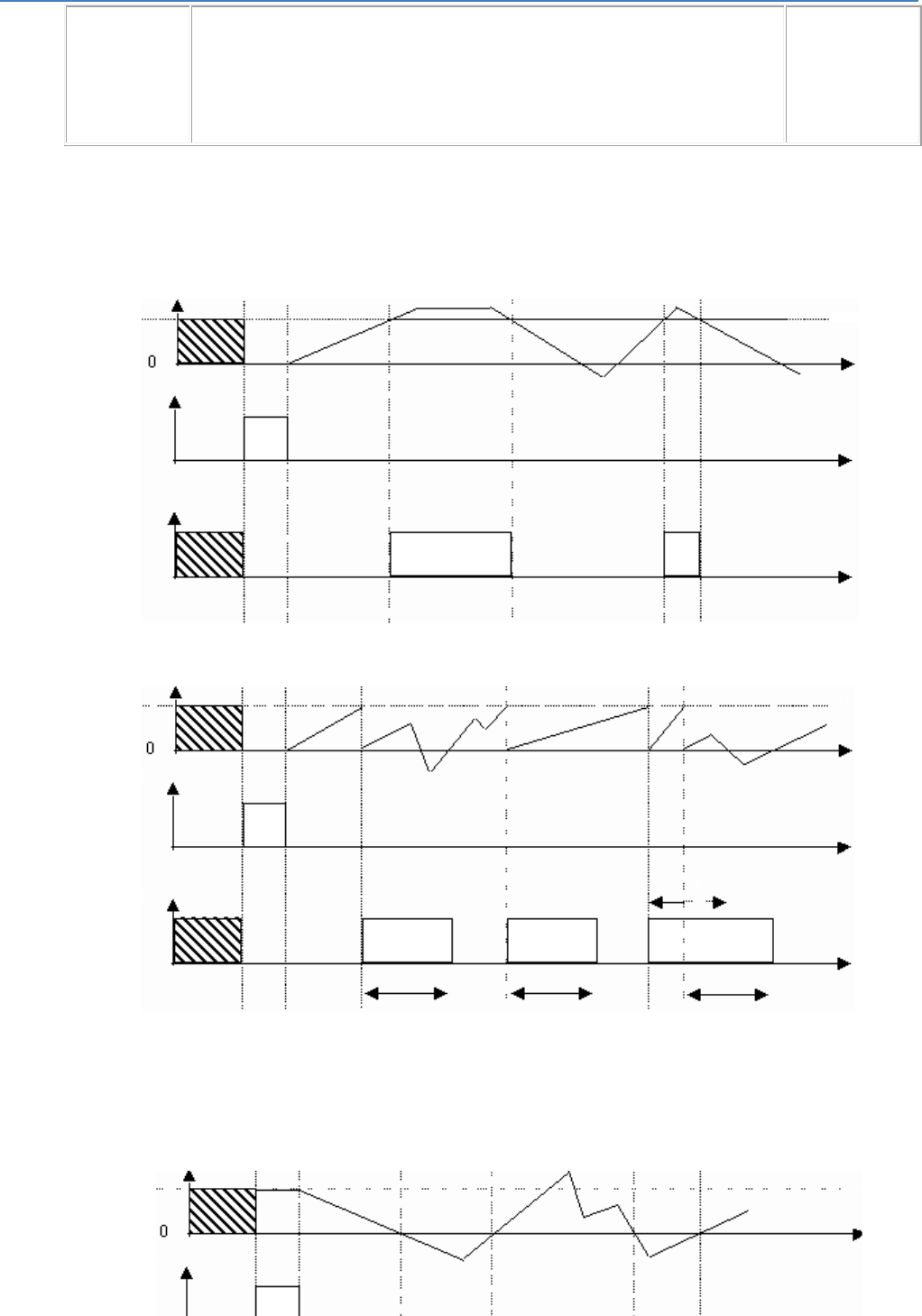
em4 soft Online Help
91
Stop
:
On Falling
edge of the
other channel
channel A
cause a return
to the previous
counter value.
Ttotal = T1 + T2 +… …+ Tn.
Single shot/repetitive cycle: Upcount to preset mode
Single shot : The output is fixed or pulsed
The pulse is adjustable in 100 ms intervals from +1 to +32,767
Counte
r
Reset
Output
Prese
t
Repetitive cycle : The output is pulsed
The pulse is adjustable in 100 ms intervals from +1 to +32,767
Counter
Reset
Output
Preset
Time Delay Time Delay Time Delay
Single shot/repetitive cycle: Downcount from preset mode
Single shot : The output is fixed or pulsed
The pulse is adjustable in 100 ms intervals from +1 to +32,767
Compteu
r
Prese
t
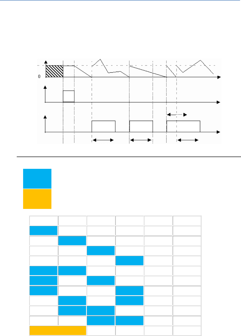
em4 soft Online Help
92
Reset
Sortie
Repetitive cycle : The output is pulsed
The pulse is adjustable in 100 ms intervals from +1 to +32,767
Counter
Reset
Output
Preset
Time Delay Time Delay Time Delay
Possible Combinations
1-channel Tachometer,
Chronometer, Period
meter
2-channel Tachometer,
Chronometer, Period
meter
I1
I2
I3
I4
Frequency
Total
60kHz
1
60kHz
1
60kHz
1
60kHz
1
40kHz
2
40kHz
2
40kHz
2
40kHz
2
40kHz
2
40kHz
2
40kHz
1
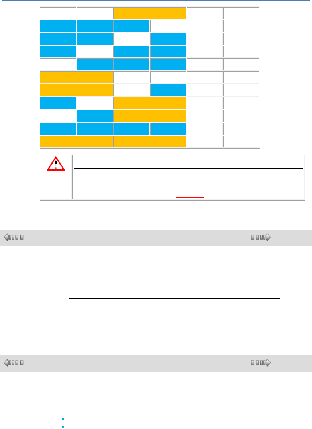
em4 soft Online Help
93
40kHz
1
30kHz
3
30kHz
3
30kHz
3
30kHz
3
30kHz
2
30kHz
2
30kHz
2
30kHz
2
20kHz
4
20kHz
2
CAUTION
If the frequency is exceeded, at first there is a loss of pulses.
If there is further increases of frequency, the WATCHDOG triggered and there is a
reset of the product.
Failure to follow these instructions can result in injury or equipment damage.
1.4.2.4 HMI/COM Functions : HMI/Communication
( § 1.4.2.3.20 )
( § 1.4.2.4.1 )
At a Glance
Subject of this Section
This section describes the different HMI/COM functions available using FBD
language.
What's in this Section?
This section contains the following topics:
Display, keys, data logging, event, recipe, etc.
1.4.2.4.1 Display on the LCD DISPLAY Screen
( § 1.4.2.4 )
( § 1.4.2.4.2 )
Description
The DISPLAY function is used to display text, a date, a time or a numerical value on
the LCD display instead of the controller INPUTS-OUTPUTS screen:
The DISPLAY function is used to display information on the following:
Text (maximum 72 characters),
Numerical values corresponding to the output of a block function used in the
application.
Up to 16 DISPLAY blocks can be enabled simultaneously in one program. If this

em4 soft Online Help
94
number is exceeded, only the first 16 blocks activated are displayed.
On the product, pressing the OK (green) and ESC (red) keys simultaneously replaces
the display on the DISPLAY screen with the menu display.
In simulation on the "Front Panel" window, click on OK with the mouse + Escape on the
keypad and simultaneously release to replace the display on the DISPLAY screen with
the menu display.
Pressing the ESC key again returns the display to the DISPLAY screen.
Note: Both ASCII-standard characters and accented characters can be used.
Note: Characters and symbols that are not displayed in the data entry window when
keyed are not supported.
Access
The DISPLAY function is accessible from the HMI function bar.
Inputs
ENABLE FUNCTION: This is the Discrete( § 1.4.2.1.1 )-type DISPLAY function
control input.
The state of this input determines block operation: if the ENABLE FUNCTION input is
active, the information is displayed on the LCD; otherwise there is no display.
If this input is not connected, then it is considered to be active.
VALUE INPUT: This is the selection input that determines the nature of the
information to be displayed. If this input is:
Not connected: The display corresponds to the selection made in the User
options zone.
Connected to the output of a function block: The display corresponds to the value
sent by this output.
Parameters
The adjustable parameters depend on whether or not the VALUE INPUT is connected
1st case: VALUE INPUT not connected
The display corresponds to the selection made in the User options zone.
Depending on the options chosen, the following can be displayed:
Text: a string of characters
Date: the current value of the internal date of the device on which the program is
executed (controller or simulator)
Time: The current internal time value
Calibration: Drift value of the controller's internal clock
2nd case: VALUE INPUT connected
The integer value present on the input is converted into a string of characters, whose
display format depends on the option that has been selected:
Integer 1/1 - 1/10000
Calendar date
Bar chart
Maxinumber
Description of the display modes:
Display mode
Description
1/1
Signed integer
1/10 - 1/10000
Signed decimal number; the fractional part represents the number of digits
following the decimal
Year
The input value must be between 1 and 99 corresponding to a display between
2001 and 2099.
Month
The input value must be between 1 and 12, corresponding to a display
indicating the first four letters of the name of the month.
Weeks
The input value must be between 1 and 31. Five digits are displayed.
Day of the month
The input value must be between 1 and 31.
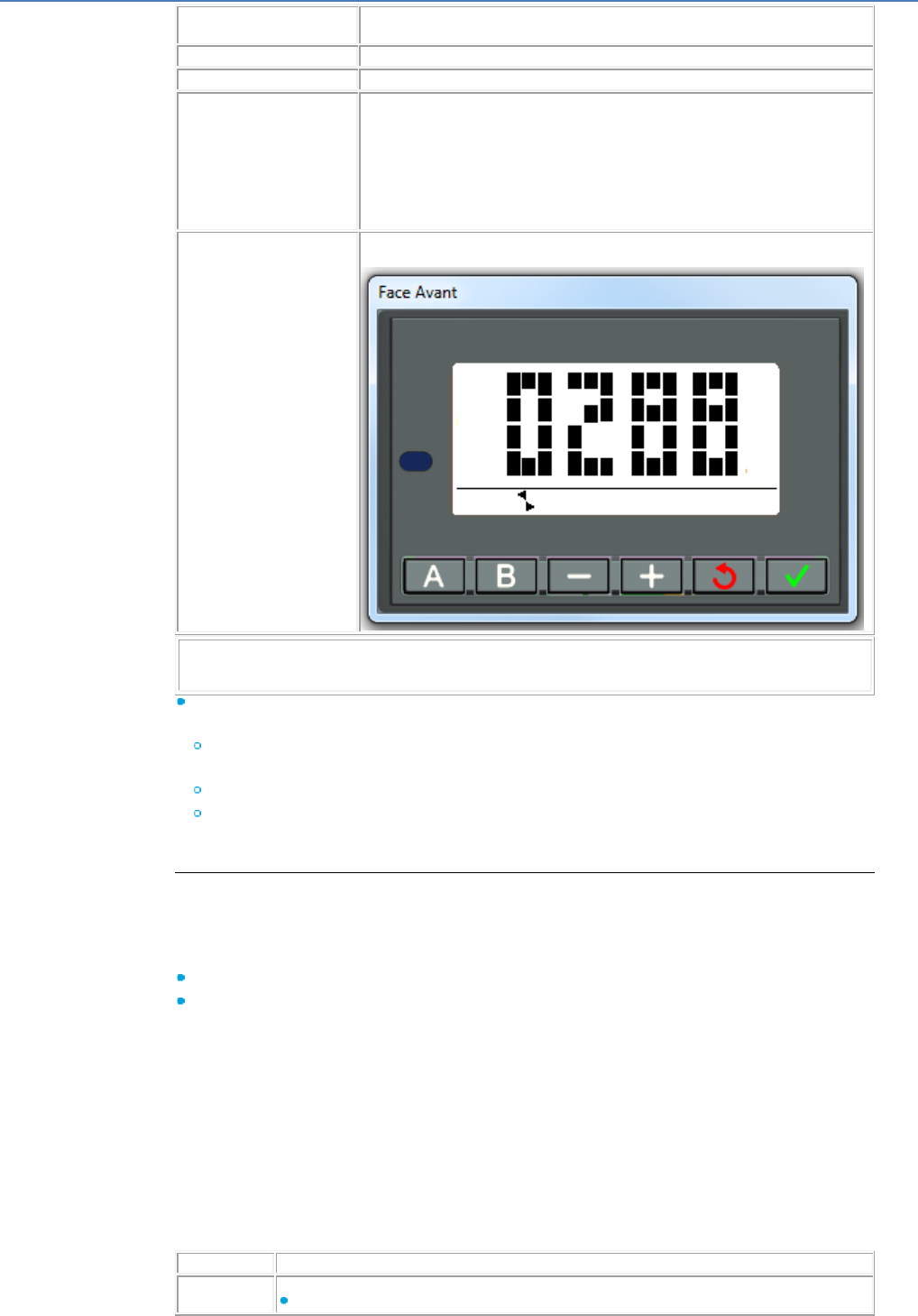
em4 soft Online Help
95
Days
The input value must be between 1 and 127. Seven letters, corresponding to
the day of the week, are displayed.
Hour
The input value must be between 0 and 23. Two numbers are displayed.
Minute
The input value must be between 0 and 59. Two numbers are displayed.
Bargraph from left to right
or from right to left
A bar is formed on the first line of the screen. The number of black squares,
from left to right or from right to left corresponds to the value of the input. For an
input of eighteen the line is completely filled. Beyond that, the line is filled by
triangles pointing to the right or to the left.
To take account of the interval in a numerical value, insert a Gain function
between the value and the DISPLAY block. For example to display a value
between 0 and 1023 as a bar chart, configure the Gain function with A=18,
B=1023.
Maxinumber
The input value is displayed so that the full height of the screen is filled.
Example
Note: For the formats Day of the month/Hour/Minute, no consistency check is carried
out.
Modification authorized: Authorizes modification directly from the screen displaying
the following values:
The integer data connected to the VALUE INPUT of function blocks (Modification
is only possible if the data can be modified).
The controller's current internal date or time value.
Correction of the drift of the controller internal clock (this last action does not work
in simulation mode).
Operating mode
Description of the interface
Each display function is identified by a block number: BXX.
This identifier is found:
On the wiring sheet: The number is located in the bottom left corner of the block
In the parameter setting window/Parameters tab: the number is in the drop-down
menu in the top left corner of the window.
The parameter setting window displays the resulting string from all blocks (BXX) used
in the wiring sheet.
The parameter setting window opens by default on the function block number from
which the dialog box was opened.
For the selected block, all text affecting it appears in orange.
In the event of any overlap, the text appears in reverse video mode in blue on an
orange background.
The non-overlapping text corresponding to the other selected blocks appears in white.
Entering one of the parameters of a DISPLAY block
Description of the entry procedure:
Step
Description
1
Is the VALUE INPUT connected?
If yes, then specify the display format.
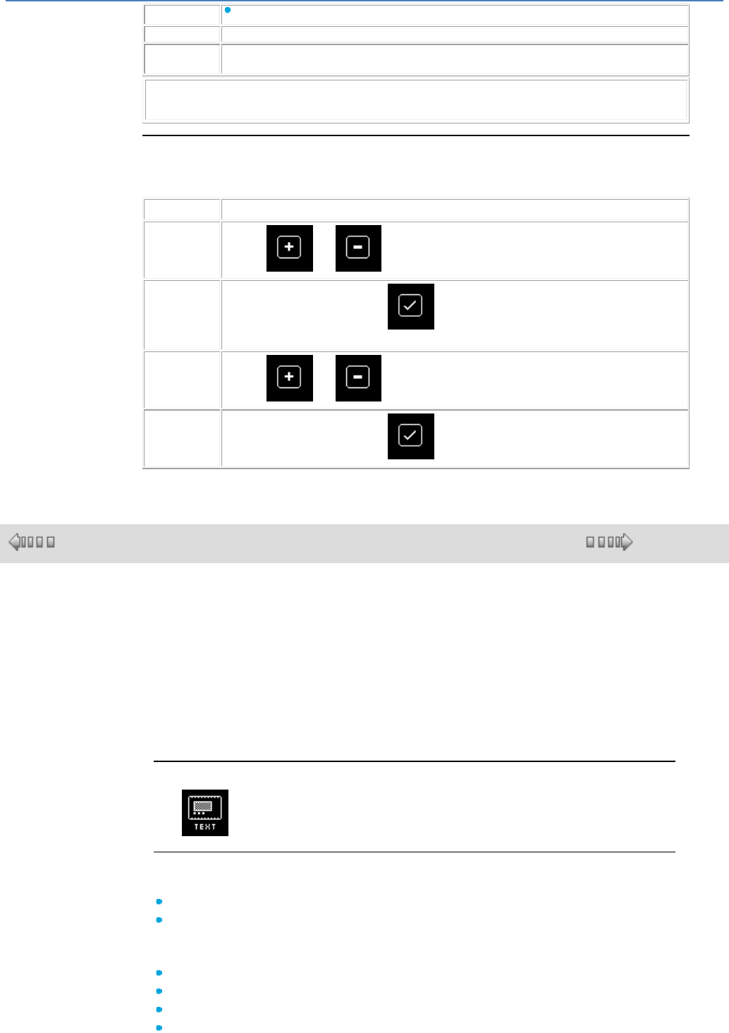
em4 soft Online Help
96
If no, then enter text in the User options box.
2
Position the start of the text using the mouse:
3
Confirm using the green OK key.
Result: The new DISPLAY block is saved and the parameters window is closed.
Note: If the strings are superimposed, a warning is displayed in the grid: the boxes
appears in blue on an orange background, all valid strings are displayed in white.
How to Modify Data from the Front Panel
When the Modification authorized option is checked, it is possible to modify the data
displayed directly from the display screen by proceeding as follows:
Step
Action
1
Use the and keys to place the cursor on the data to modify.
2
Confirm by pressing the OK key .
Result: The selected data flashes.
3
Use the and keys to scroll to the desired value.
4
Confirm by pressing the OK key .
1.4.2.4.2 TEXT Function
( § 1.4.2.4.1 )
( § 1.4.2.4.3 )
Description
The Text automation function is used to display texts and/or numerical values
(current value, preset value, etc.) on the LCD display instead of the INPUTS-
OUTPUTS screen:
Several text blocks can be used simultaneously in one program, but only the block
with the highest number is displayed.
Pressing the green OK and red ESC keys simultaneously replaces the display on
the TEXT screen with the main menu display.
Pressing the ESC key again returns the display to the TEXT screen.
Access
The function is accessible from the HMI function bar.
Inputs
The Text function has two discrete inputs:
Set: Activation of the Set input prompts the display.
Reset: Activation of the Reset input cancels the display. Reset has priority over
Set.
The Text function has four analog inputs which are displayable values.
Value 1
Value 2
Value 3
Value 4

em4 soft Online Help
97
Character String Display
The cursor is positioned at the start of the string displayed in the window:
By left-clicking on the box (which then flashes)
By using the arrow keys on the computer keyboard
Description of the entry procedure:
Step
Action
1
Position the cursor at the start of the text.
2
Type the text to be displayed using the keyboard.
3
Confirm by clicking OK.
Result: The new Text block is saved and the parameter-setting window is closed.
Note: The character string is limited to four lines. If the user continues to enter
characters, each additional character overwrites the one in the last box.
Note: Both ASCII-standard characters and accented characters can be used.
Characters and symbols that are not displayed in the data entry window when
keyed are not supported.
Note: If the text entered on a line covers an existing numerical value, the latter is
deleted.
If a numerical value is positioned over text that has already been entered, the
characters it covers are overwritten.
Displaying a Numerical Value
Positioning:
To position the value (4 maximum) on the line, simply drag and drop it to the edit
window.
Selection:
The value to be displayed is selected in the window located above the edit window.
This window lists the following elements:
Date: The current value of the internal date (day.month.year) of the device on
which the program is executed (controller or simulator)
Hour: The current internal time value (hours:minutes)
Calibration( § 1.3.4.1.1 ): Drift value of the controller’s internal clock
List of displayable values, i.e. the function analog inputs
Clear Text
Description of the procedure:
Step
Description
1
Activate the zone to be cleared.
With the mouse: Left-click, move the mouse over the zone to be selected, holding down
the left mouse button, then release the button.
Result: The selected zone flashes.
2
Clear using the Delete key on the keyboard.
1.4.2.4.3 MENUSCROLL
( § 1.4.2.4.2 )
( § 1.4.2.4.4 )
This function is used to set one of the digital outputs to ON.
Inputs:
VALIDATION : Function validation input. Until this input is activated, the function
remains inert. VALIDATION is active implicitly if it has not been connected.
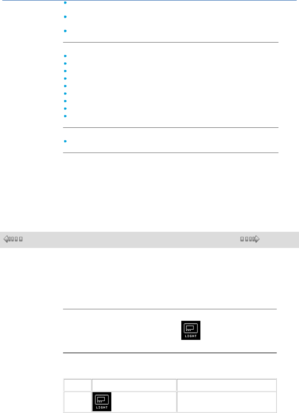
em4 soft Online Help
98
PLUS input : Sets the active output to OFF and the next to ON provided that the
number in "Number of outputs" has not been reached.
MINUS input: Sets the active output to OFF and the previous one to ON provided
that the "Active position number" is other than 1.
RESET : Resets the first output to ON and all the others to OFF.
Outputs:
Position 1.
Position 2.
Position 3.
Position 4.
Position 5.
Position 6.
Position 7.
Position 8.
Active position number.
Parameters:
Number of outputs : Defines the number of digital outputs used [2 ..8].
Only one output is active at a time. It is selected by means of the PLUS and MINUS
inputs. At the start, position 1 is at ON then subsequent ones can be set to ON in
succession until "Active position number" = "Number of outputs".
While the Reset input is active, all outputs are set to OFF and once deactivated,
only position 1 is at ON.
This function can be useful for menu scrolling if displays are wired as outputs.
1.4.2.4.4 LCD Screen Backlighting Output
( § 1.4.2.4.3 )
( § 1.4.2.4.5 )
At a Glance
The LCD Screen BACK LIGHT screen Backlighting output is used to control
backlighting of the controller LCD display by the program, by default Backlighting is
on.
As long as the input is not connected or connected and active, backlighting is on.
This function cannot be arranged on the controller outputs.
Access
The LCD Screen Backlighting Output function is accessible from the
HMI/COM window.
Simulation and Debugging Modes
The following table lists the symbols of the LCD Screen Backlighting function in
Simulation or Debugging modes.
Input State
Symbol in Simulation and Debugging
mode
Description
Inactive
The LCD screen is off.
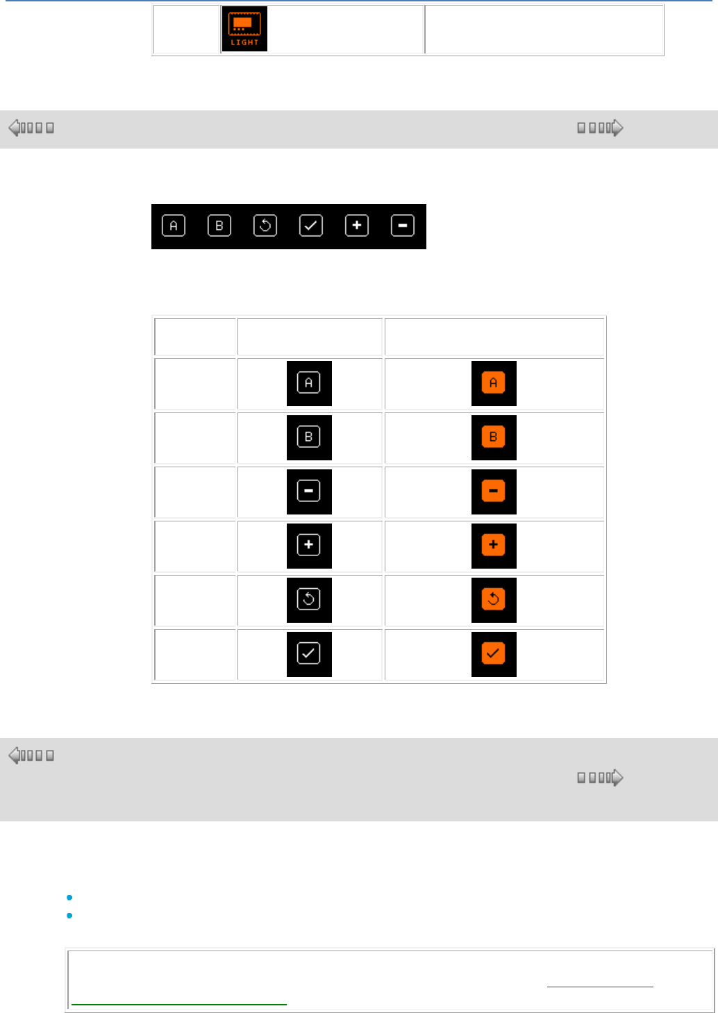
em4 soft Online Help
99
Active
The LCD screen is back-lit.
1.4.2.4.5 Buttons on the Front Panel
( § 1.4.2.4.4 )
( § 1.4.2.4.6 )
Button-type Inputs
Button-type inputs correspond to the keys available on the front panel of the
controller. These inputs can be inserted in an FBD diagram and, in Simulation and
Debugging mode, can simulate contacts
Type
Display in Inactive
state
Display in Active state
A
B
-
+
Esc
OK
1.4.2.4.6 DATALOGGING
( §
1.4.2.4.
5 )
( § 1.4.2.4.7 )
Description
When the function bloc Datalogging is activated, it allows to:
Send alarm messages to mobile phones, for the Alert version.
Send alarm data to em4-web, for the Remote version.
It is possible to use up to 3 Datalogging function blocs in the same program.
Note : The Datalogging function is only available on the controllers having a commmunication board.
For more informations about the communication interface, please refer to the Communication
Interface via the 2G Connection( § 1.5.4 ) page.
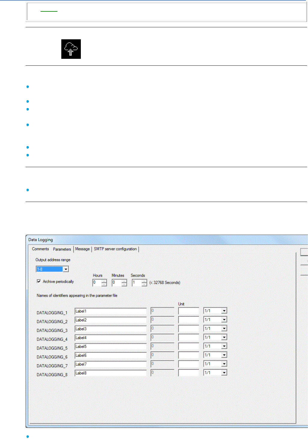
em4 soft Online Help
100
The Event( § 1.4.2.4.7 ) function have priority on the Datalogging function.
We cannot simulate this function.
Access
This function is accessible from the function bar HMI/COM.
Inputs
The Datalogging function bloc contains the following inputs:
Command, according to the setting of the function bloc, the data are sent during the detection of a
rising front on this input or periodically,
Value1, digital variable associated with this function bloc
Value2, digital variable associated with this function bloc
.... .... .... ....
Value8, digital variable associated with this function bloc
The values of variables connected to the inputs Value1 to Value8 (according to the configuration of the
function bloc) can be:
Displayed in messages sent by SMS or email, for the Alert version.
Sent to em4-web, for the Remote version.
Outputs
The Datalogging function bloc contains the following output:
State, each time the function bloc is validated, this output is ON during the recording.
Setting from the workshop
Double-click on the function bloc to open the configuration window. Use the various tabs of this window to
configure the bloc.
In the Parameter tab:
Adress range of outputs: Allows to choose to which group of address the block belongs: 1-8, 9-16 or
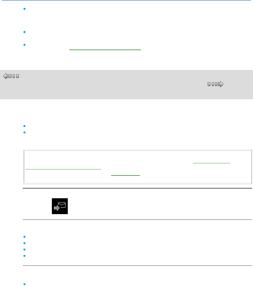
em4 soft Online Help
101
17-24.
Archive periodically: if the box is not marked, it is the rising front on the Command input which
validate the sending of data.
If the box is marked, the data are sent periodically according to time parametrized in box Hours
Second Minutes
Names of identifiers: Names of identifiers are saved in a parameter file.
In the Message tab:
This tab allows the Composition of an SMS/Email( § 1.5.4.4 )
1.4.2.4.7 EVENT
( §
1.4.2.4.
6 )
( § 1.4.2.5 )
Description
When the Event function bloc is activated, it allows to:
Send alarm messages to mobile phones, for the Alert version.
Send alarm data to em4-web, for the Remote version.
It is possible to use up to 24 Event function blocks in the same program corresponding to 24 events
numbers.
Note : The Event function is only available on the controllers having a commmunication board.
For more informations about the communication interface, please refer to the Communication
Interface via the 2G Connection( § 1.5.4 ) page.
The Event function have priority on the Datalogging( § 1.4.2.4.6 ) function.
We cannot simulate this function.
Access
This function is accessible from the HMI/COM function bar.
Inputs
The Event function block has the following inputs:
Command, data are sent upon the detection of a rising edge on this input,
Value1, numerical variable associated with this function block,
Value2, numerical variable associated with this function block,
Reset Ack Appli, reset the sendings in case of no answer.
Output
The Event function block has the following output:
Output ACK Network, indicates the correct sending of the information :
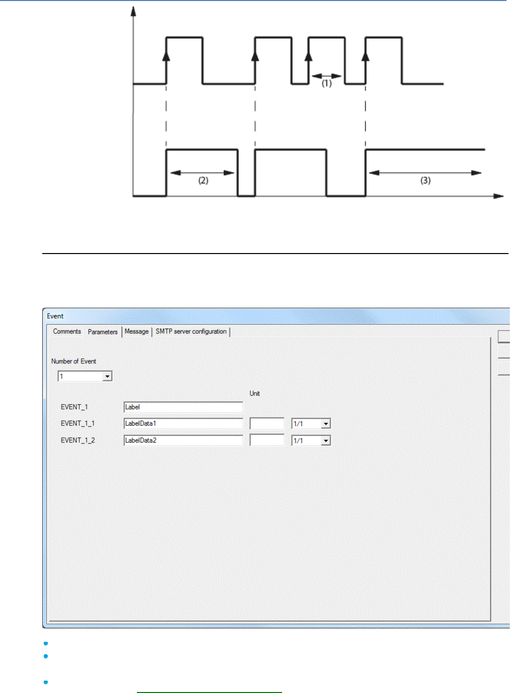
em4 soft Online Help
102
Output ACK
Network
Command
(1) Sending ignored
(2) Sending in progress
(3) Fault, activate the Reset Ack Appli input.
Setting from the workshop
Double-click on the function bloc to open the configuration window. Use the various tabs of this window to
configure the bloc.
In the Parameter tab:
Number of Event: Allows to choose the number of the event associated with the FB: 1 to 24.
EVENT_N: The event is saved in a parameter file.
In the Message tab:
This tab allows the Composition of an SMS/Email( § 1.5.4.4 )
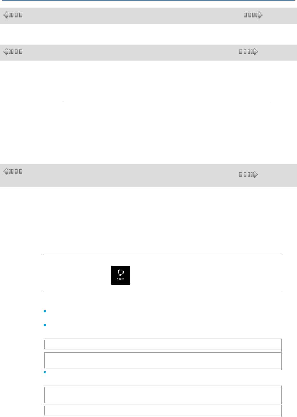
em4 soft Online Help
103
1.4.2.4.8 RECIPE
( § 1.4.2.4.7 )
( § 1.4.2.5 )
1.4.2.5 APP functions : Application
( § 1.4.2.4.8 )
( § 1.4.2.5.1 )
At a Glance
Subject of this Section
This section describes the different APP functions available using FBD language.
What's in this Section?
This section contains the following topics:
Cam timer, pump management, level, temperature, twilight, solar tracking,
filtration, heat curve, PID, etc.
1.4.2.5.1 CAM BLOCK Cam Programmer
( §
1.4.2.5 )
( § 1.4.2.5.2 )
At a Glance
The cam programmer function CAM BLOCK controls a set of 8 built-in cam wheels.
On its 8 outputs (representing the 8 wheels), the function provides the state corresponding to
the current position of the shaft wheels.
The cam configuration can be set; for each position, output state is adjustable.
Once the maximum value has been reached, the cam restarts from its initial position (output
returns to 0).
Access
The CAM BLOCK function is accessible from the APP function bar.
Inputs/Outputs
Description of the inputs:
MOVE FORWARD: this is the input that controls cam progress; it moves one step forward
at each rising edge (change from inactive to active).
MOVE BACKWARD: this is the input that controls backward cam movement; it moves one
step backward at each rising edge (change from inactive to active).
Note: The MOVE FORWARD input takes priority over the MOVE BACKWARD input.
Note: If the MOVE FORWARD and MOVE REVERSE inputs are not connected, they are
set to inactive.
RESET (initialization): When this input is active, the cam is replaced to its initial position:
the POSITION output is forced to 0.
Note: The RESET input takes priority over the MOVE FORWARD and MOVE BACKWARD
inputs.
Note: If the RESET input is not connected, it is set to inactive.
Description of the outputs:
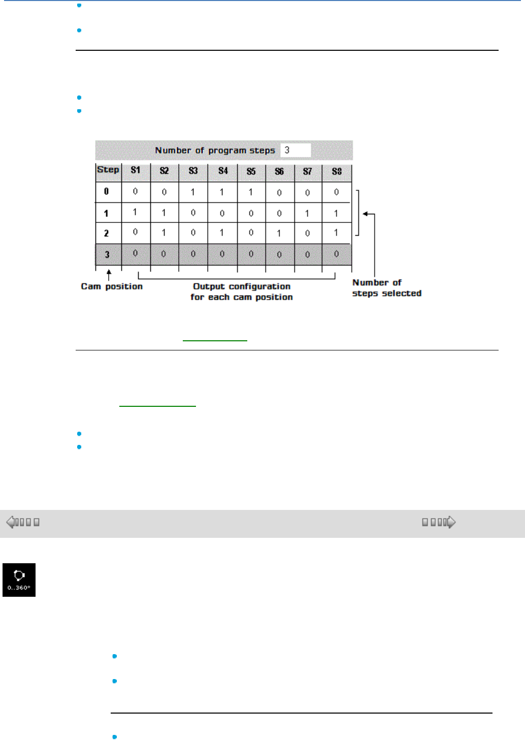
em4 soft Online Help
104
OUTPUT 1 to 8: state corresponding to the current position of the shaft (representing the 8
wheels),
POSITION: current cam position (0 to 49).
Parameters
From the programming workshop
From the Parameters window, you may adjust:
The number of program steps: Its value is between 1 and 50,
Output status [1..8]: for each position of the shaft.
The following figure shows an example of a part of parameters window:
When selected, the Save on power fail parameter enables the current value of the timer to
be retrieved following a power failure( § 1.2.20 ).
Modification of Parameters from the Front Panel
To modify the parameters from the front panel of the controller, check the Authorized
modification box of the Parameters window.
From the PARAMETERS( § 1.3.2 ) menu, it is possible to modify bit-wise the contents of all
the cam programmer steps, but it is not possible to modify the number of steps.
After you have entered the block number, then enter:
The step number: Value between [0..49],
Output status [1..8]: For each output one can set the value to INACTIVE (empty diamond)
or ACTIVE (black diamond).
1.4.2.5.2 ANGULAR CAM TIMER
( § 1.4.2.5.1 )
( § 1.4.2.5.3 )
This function describes operation of a cam timer with the angle made by the cams as
the command input. The number of steps can be selected, as can the state of the 2
outputs.
Inputs:
VALIDATION : Enables the function. If this input is not activated, the function
remains inactive. Activated implicitly if it has not been connected.
ANGLE : Timer command input (from 0° to 359°). The outputs vary according to
this value and the OUTPUT STATE parameter.
Outputs:
OUTPUT 1 : Output 1 is related to the value in the OUTPUT 1 column in the
em4 soft Online Help
105
OUTPUT STATE table. If the value of the angle in the ANGLE input is higher or
the same as a value N in the ANGLE column in the OUTPUT STATE table and
less than the value N+1 in the table, the value of the corresponding OUTPUT 1
column is copied to OUTPUT 1 (1 => output at ON, 0 => output at OFF).
OUTPUT 2 : Output 2 is related to the value in the OUTPUT 2 column in the
OUTPUT STATE table. If the value of the angle in the ANGLE input is higher or
the same as a value N in the ANGLE column in the OUTPUT STATE table and
less than the value N+1 in the table, the value of the corresponding OUTPUT 2
column is copied to OUTPUT 2 (1 => output at ON, 0 => output at OFF).
Parameters:
NUMBER OF DEGREES Equivalent to the wheel step number (2 to 72 steps of 5°
to 180°).
OUTPUT STATES : Table summarising the output states for each position. These
states can be modified by clicking in the corresponding boxes.
1.4.2.5.3 PUMPS MANAGEMENT (Tank management with circular pump changeover)
( §
1.4.2.5.2 )
( § 1.4.2.5.4 )
This function is used to set to ON a maximum of four digital outputs which can be activated
(OUTPUT 1 ... OUTPUT 4). This number is equal to the maximum number of digital inputs (from 2
to 4) in the ON state. In addition, the outputs set to ON are selected so that in the event of
prolonged operation, each output will have been set to ON the same number of times.
The ON duration of the outputs is set to equal values by applying the following technique:
As the number of ON inputs increases, the outputs changing to ON are those following the
order of the PILOT OUTPUT NUMBER: 1 for OUTPUT 1, 2 for OUTPUT 2, 3 for OUTPUT 3
and 4 for OUTPUT 4. For example, if the "outputs controlled" parameter has the value 4, if
PILOT OUTPUT NUMBER has the value 3 and just one input is set to ON, only the OUTPUT 3
output will be set to ON. As soon as two inputs change to ON, the OUTPUT 3 output remains
at ON and the OUTPUT 4 output changes to ON. As soon as a third input changes to ON, the
OUTPUT 3 and OUTPUT 4 outputs remain ON and OUTPUT 1 changes to ON.
As soon as the number of outputs decreases, the outputs changing to OFF will be those which
have been in the ON state the longest. As soon as one output changes to OFF, PILOT
OUTPUT NUMBER takes the value of the output number after the output(s) which has (have)
just been set to OFF. To complete the above example, as soon as one input changes to OFF,
the OUTPUT 3 output changes to OFF and PILOT OUTPUT NUMBER displays the integer
value 4.
The Parameters tab in the parameterisation box contains the number of outputs which may
change to ON depending on the number of inputs which are set to ON. The values of this
parameter are fixed at 2, 3 or 4.
If the value of the parameter is fixed at 2, only the OUTPUT 1 and OUTPUT 2 outputs are used
and may therefore change to ON. In this case, if more than two inputs change to ON, the
OUTPUT 1 and OUTPUT 2 outputs remain at ON and the OUTPUT 3 and OUTPUT 4 outputs
remain fixed at OFF.
If the value of the parameter is fixed at 3, only the OUTPUT 1, OUTPUT 2 and OUTPUT 3
outputs are used and may therefore change to ON. . In this case, if four inputs change to ON,
the OUTPUT 2, OUTPUT 2 and OUTPUT 3 outputs remain at ON and OUTPUT 4 remains
fixed at OFF.
If the value of the parameter is fixed at 4, only the OUTPUT 1, OUTPUT 2, OUTPUT 3 and
OUTPUT 4 outputs are used and may therefore change to ON.
All inputs which are not connected have the value OFF.
When the program is initialised, PILOT OUTPUT NUMBER is fixed at 1.
The Parameters tab contains the default check box which reinitialises PILOT OUTPUT NUMBER
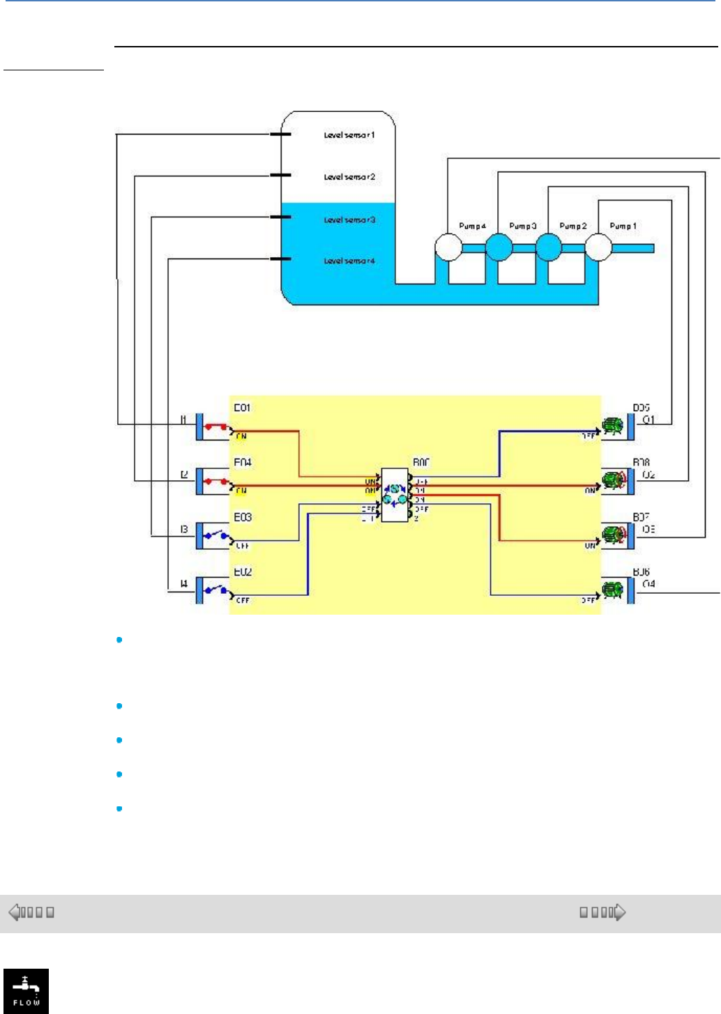
em4 soft Online Help
106
to 1 (and defines the first output activated when the first input changes to 1) after a controller
power failure.
Example of use:
Filling a tank with a group of four pumps operating in parallel. The operating duration of each
pump is the same.
The "number of outputs controlled" parameter is fixed at 4.
On initialisation, PILOT OUTPUT NUMBER has the value 1. On initialisation, if the tank is in
the state indicated and if a sensor above the water is in the ON state, when the user program is
executed, the INPUT 1 and INPUT 2 inputs are ON, INPUT 3 and INPUT 4 are OFF and
OUTPUT 1 and OUTPUT 2 are ON.
Assuming that the tank is full, INPUT 2 changes to OFF and OUTPUT 1 changes to OFF.
PILOT OUTPUT NUMBER indicates the value 2.
Assuming that the tank is empty, INPUT 2 changes back to ON, OUTPUT 3 changes to ON
and OUTPUT 2 remains ON.
Assuming that the tank refills, INPUT 2 changes back to OFF, OUTPUT 2 changes to OFF and
PILOT OUTPUT NUMBER indicates the value 3.
Assuming that the tank continues to refill, INPUT 1 changes to OFF, OUTPUT 3 changes to
OFF and PILOT OUTPUT NUMBER indicates the value 4.
1.4.2.5.4 FLOW
( § 1.4.2.5.3 )
( § 1.4.2.5.5 )

em4 soft Online Help
107
This function enables the flow of a liquid in a pipe to be calculated using a differential
pressure element or by measuring the dynamic pressure.
Inputs:
"VALIDATION" input : The status of this VALIDATION input determines the
operation of the block:
if the VALIDATION input is inactive, the calculation output retains the latest
calculated value.
if the VALIDATION input is not connected, it is deemed to be active.
PRESSURE 1 input : value of pressure sensor P1 (in mbar).
PRESSURE 2 input : value of pressure sensor P2 (in mbar).
EXTERNAL DENSITY input : value of density if the "External" box on the
parameters page is checked (in kg/m3).
Outputs:
CALCULATION ERROR : equal to ON if the calculated flow is less than -32768,
greater than 32767 or if P1 is less than P2 or if D1 is less than D2, the volumetric
flow rate output is set to 0.
VOLUMETRIC FLOW RATE : result of calculation (in l/s).
INTERNAL DENSITY : value used to calculate the flow if the "External" box is not
checked (in kg/m3, can be modified via display).
Parameters:
Sensor type : choice of sensor used.
Constant : D1, D2 or S depending on the sensor used.
Density : value used to calculate the flow if the "External" box is not checked (in
kg/m3).
Warnings relating to the use of this function:
A) This block is only suitable for incompressible liquids, i.e. those whose density is
not affected by temperature.
B) The flow regime is described as "turbulent" and not laminar. Most industrial
applications have a turbulent flow regime. Re > 4000.
This block is not suitable for gases.
C) The design of the differential pressure elements must comply with the standards
ISO 5167-1, ISO 5167-2, 5167-3 and 5167-4 for Europe, API 2530 for USA.
D) The pipe must be full and not contain any deposits. The operation of the system
is continuous, with little variation in pressure and temperature. The medium must
be homogeneous and unvarying over time.
1°) Differential pressure element:
There are three main types of differential pressure element:
diaphragm
venturi
nozzle
2°) Flow metering by dynamic pressure:
There are two main types:
pitot sensor
annubar or Barton sensor
The only difference between the two is a constant. In the first case it is a coefficient
relating to the differential pressure element, in the second case it concerns the cross-
section of the pipe.
OPERATION:
The flow calculation is based on the differential pressure elements. Any flow
measurement using a differential pressure element involves an obstacle that creates
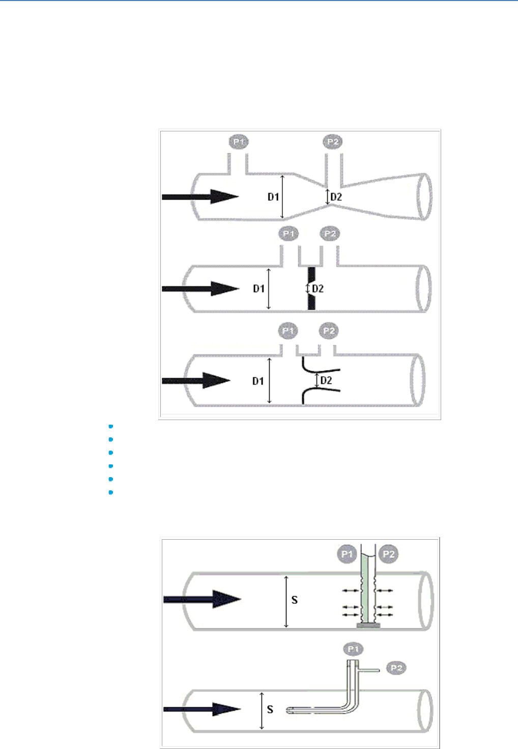
em4 soft Online Help
108
a delta P and a measurement of differential pressure; this makes it necessary to
perform two pressure measurements.
The main advantage of a flow meter with a differential pressure element is that there
is no need to go through a calibration process, provided that these elements have
been designed in accordance with the established standards (ISO 5167-1, ISO 5167-
2, 5167-3 and 5167-4 for Europe, API 2530 for USA).
All these standards are derived from the work of Bernoulli. We regard flow
measurements as only possible within the framework of a constant density..
1°) Differential pressure element:
Practical expression of flow for a differential pressure flow meter:
D1: upstream diameter in cm (1 ≤ D1 ≤ 100).
D2: downstream diameter in cm (0 ≤ D2 ≤ 100).
Density of liquid in kg/m3 (500 ≤ p ≤ 4000).
P1: upstream pressure measurement in mbar.
P2: downstream pressure measurement in mbar.
P1 > P2
2°) Flow metering by dynamic pressure:
Practical expression of flow with a dynamic pressure flow meter:
em4 soft Online Help
109
S: constant: cross-section of pipe in cm2 (0 ≤ S ≤ 10000).
Density of liquid in kg/m3 (500 ≤ p ≤ 4000).
P1: upstream pressure measurement in mbar.
P2: downstream pressure measurement in mbar.
P1 > P2
1.4.2.5.5 LEVEL
( § 1.4.2.5.4 )
( § 1.4.2.5.6 )
This function allows to calculate the level of a liquid, with or without constant
density, in an open or closed tank, using pressure sensors.
Inputs:
"VALIDATION" input : the status of this VALIDATION input determines the
operation of the block:
if the VALIDATION input is inactive, the calculation output retains the latest
calculated value.
if the VALIDATION input is not connected, it is deemed to be active.
PRESSURE 1 input : value of pressure sensor P1 (in mbar).
PRESSURE 2 input : value of pressure sensor P2 (in mbar).
PRESSURE 3 input : value of pressure sensor P3 (in mbar).
Outputs:
LEVEL FAULT : equal to ON if the calculated level is less than the low level
value entered on the parameters page.
CALCULATION FAULT : equal to ON if there is not P1 > P3 > P2 at the inputs.
LEVEL CALCULATION OUTPUT : result of calculation (in cm).
Parameters:
Type of tank : choice of tank used (type A, B, C or D).
Density of liquid : Density of liquid used in the tank (in kg/m3), in the case of
constant density (tank type A or B).
Height of sensor P3 : Distance between sensors P3 and P1 (in cm), in the case
of variable density (tank type C or D).
Low level : tank level monitoring value (in cm), activates the LEVEL FAULT
output.
Some common densities expressed in kg/m3:
Water
1000
Acetone
790
Acetic acid
1049
Seawater
1030
Ethanol
789
Ether
710
Glycerine
1260
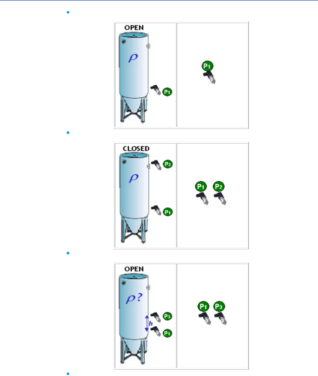
em4 soft Online Help
110
Description of tank types A, B, C and D and calculation methods:
Tank type A (open tank with known and stable density):
Tank type B (closed or pressurised tank with known and stable density):
Tank type C (open tank with unknown or unstable density):
Tank type D (closed or pressurised tank with unknown or unstable density):
em4 soft Online Help
111
1.4.2.5.6 NTC1
( § 1.4.2.5.5 )
( § 1.4.2.5.7 )
This function carries out the temperature measurement. It is dedicated to NTC1
(-25 to +85 °C).
Input:
ANA Input: Input connected to the product analog input (potentiometer).
Output:
Temperature : gives the temperature in °C * 100.
Output parameter:
Correction: correction of temperature by step of 1/10 of °C.
1.4.2.5.7 NTC2
( § 1.4.2.5.6 )
( § 1.4.2.5.8 )
This function measures temperature. It is designed for NTC2 type CTNs (-35°C
to +120°C).
Input:
Analog input : Input connected to the product analog input (potentiometer).
Output:
Temperature : Gives the temperature in °C * 100.
Output parameter:
Correction : Temperature correction in steps of 1/10th of a °C.
em4 soft Online Help
112
1.4.2.5.8 NTC3
( § 1.4.2.5.7 )
( § 1.4.2.5.9 )
This function measures temperature. It is designed for NTC3 type CTNs (0°C to
+200°C).
Input:
ANALOG INPUT : Input connected to the product analog input
(potentiometer).
Output:
TEMPERATURE : Gives the temperature in °C * 100.
Output parameter:
CORRECTION : Temperature correction in steps of 1/10th of a °C.
1.4.2.5.9 LUX-I : Interior light sensor
( § 1.4.2.5.8 )
( § 1.4.2.5.10 )
This function measures light. It is designed for photoresistors and internal light
meters, i.e. for values between 0 and 8000 Lux.
Input:
ANALOG INPUT : Input connected to the product analog input (potentiometer).
Output:
MEASURED VALUE : Gives the light level in Lux.
Application example :
88 970 183, luminosity probe LDR-I, from 0 to 3000 Lux.
1.4.2.5.10 TWILIGHT Sunset / Sunrise
( §
1.4.2.5.
9 )
( § 1.4.2.5.11 )
This function calculates the sunrise and sunset times and also the twilight times in relation to the latitude
and longitude read on the function block inputs. It is used to generate high levels on its "MORNING
PULSE" and "EVENING PULSE" outputs according to the user parameters.
Inputs:
Controller geographical coordinates:

em4 soft Online Help
113
LONGITUDE : value between -18000 and 18000 (representing -180°00 to 180°00, East (-), West (+)).
LATITUDE : value between -9000 and 9000 (representing -90°00 to 90°00, South (-), North(+)).
TIME ZONE : represents the time difference in minutes compared with GMT depending on the country
where the controller is located.
Note: the latitude and longitude must be entered in hundredths. Example: 8962 for an actual value of
89°62.
Outputs:
SUNRISE HOUR : represents the sunrise hour in relation to the geographical position and date of the
controller.
SUNRISE MINUTE : represents the sunrise minutes in relation to the geographical position and date of
the controller.
SUNSET HOUR : represents the sunset hour in relation to the geographical position and date of the
controller.
SUNSET MINUTE : represents the sunset minutes in relation to the geographical position and date of
the controller.
MORNING PULSE : this output is at ON when the conditions entered in the parameters are fulfilled
(see parameters).
EVENING PULSE : this output is at ON when the conditions entered in the parameters are fulfilled (see
parameters).
Parameters:
SUNRISE/SUNSET TYPES:
CIVIL TWILIGHT : used to calculate the time when the sun is 6° below the horizon at sunrise (dawn)
and sunset (twilight).
NAUTICAL TWILIGHT : used to calculate the time when the sun is 12° below the horizon at sunrise
(dawn) and sunset (twilight).
ASTRONOMICAL TWILIGHT : used to calculate the time when the sun is 18° below the horizon at
sunrise (dawn) and sunset (twilight).
SUNRISE/SUNSET : represents the official sunrise and sunset times.
MANUAL : Used to select the height of the sun, in degrees, for calculating the official sunrise and
sunset times (-20°0 to 0°0 in increments of 0.1).
SUNRISE HOUR MINUTES:
START : represents the time when the MORNING PULSE output changes to ON if Fixed is
checked.
Negative OFFSET represents the offset to be subtracted from the sunrise hour minute value if
Offset - is checked. In this case the value obtained represents the time when the MORNING PULSE
output changes to ON.
END : Represents the time when the MORNING PULSE output changes to OFF if Fixed is checked.
Positive OFFSET represents the offset to be added to the sunrise hour minute value if Offset + is
checked. In this case the value obtained represents the time when the MORNING PULSE output
changes to OFF.
SUNSET HOUR MINUTES:
START : represents the time when the represents the time when the EVENING PULSE output
changes to ON if Fixed is checked.
Negative OFFSET represents the offset to be subtracted from the sunset hour minute value if Offset
- is checked. In this case the value obtained represents the time when the EVENING PULSE output
changes to ON.
END : represents the time when the EVENING PULSE output changes to OFF if Fixed is checked.
Positive OFFSET represents the offset to be added to the sunset hour minute value if Offset + is
checked. In this case the value obtained represents the time when the EVENING PULSE output
changes to OFF.
Operating diagram:
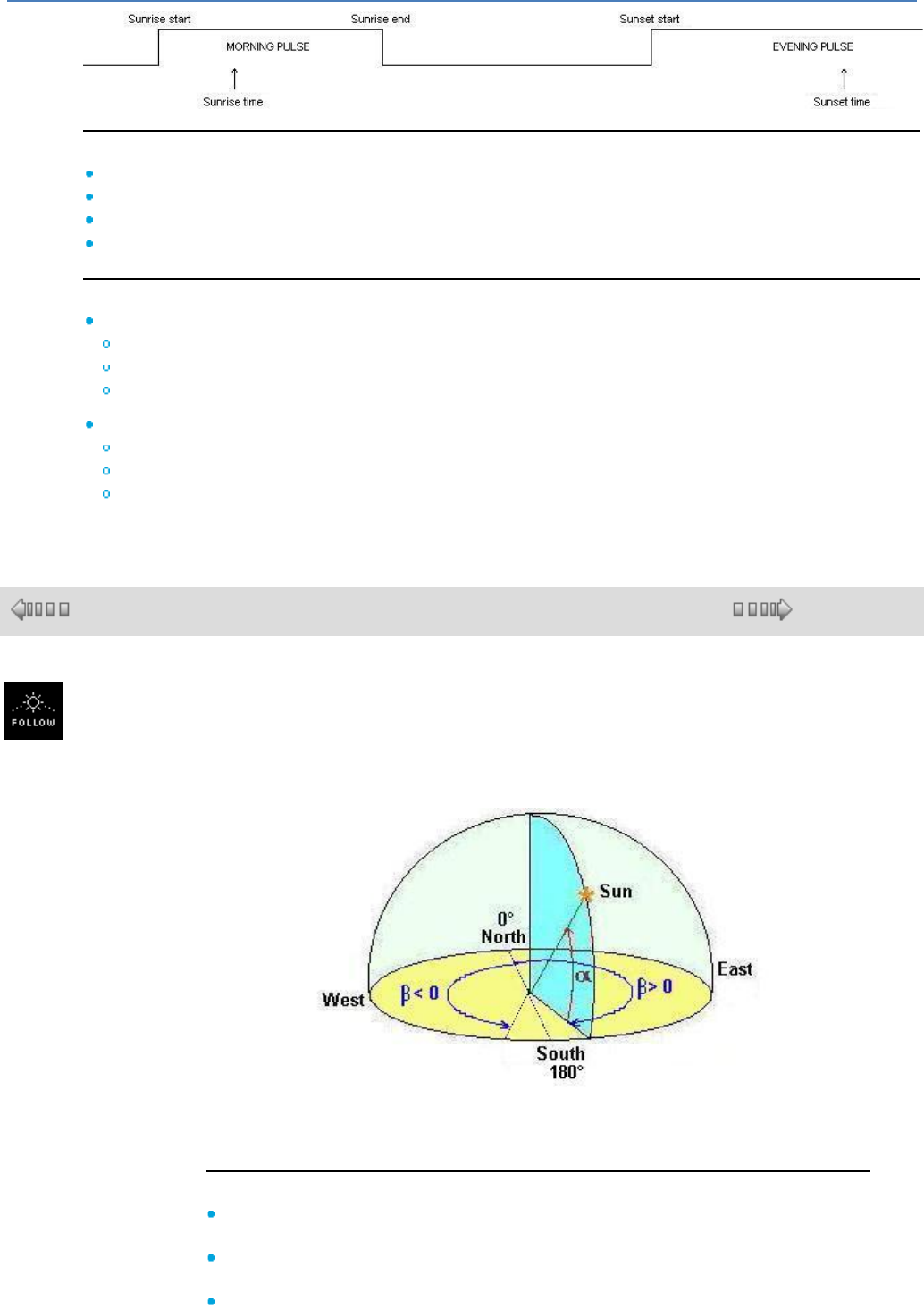
em4 soft Online Help
114
Particular operating scenarios:
If 'sunrise start time' is > 'sunrise time' then 'sunrise start time' = 'sunrise time' – 1 min.
If 'sunrise end time' is < 'sunrise time' then 'sunrise end time' = 'sunrise time' + 1 min.
If 'sunset start time' is > 'sunset time' then 'sunset start time' = 'sunset time' – 1 min.
If 'sunset end time' is < 'sunset time' then 'sunset end time' = 'sunset time' + 1 min.
Example :
Paris : latitude = 48°51N, longitude = 2°20E
Latitude = 4885
Longitude = -233
Time zone = 60
Buenos Aires : latitude = 34°20S, longitude = 58°30W
Latitude = -3433
Longitude = 5850
Time zone = -180
1.4.2.5.11 SOLAR TRACKING: DUAL AXIS
( § 1.4.2.5.10 )
( § 1.4.2.5.12 )
This function calculates the sun's position so that a sun dial can be placed. This
positioning depends on the two angles calculated by the function: the elevation
angle and the azimuth angle (see diagram).
Alpha: Elevation, Beta: Azimuth.
To do this calculation, the function uses latitudes and longitudes, the date and time
zone of the measurement location.
Inputs:
VALIDATION : function validation input. Until this input is activated, the function
remains inert. Validation is active implicitly if it has not been connected.
LATITUDE : represents the latitude at the measurement location (-90°00 S to
90°00 N).
LONGITUDE :represents the longitude at the measurement location (-180°00 E

em4 soft Online Help
115
to 180°00 W).
Note : : the latitude and longitude must be entered in the following format: 8962
for an actual value of 89°62.
Note : : the latitude and longitude must be entered in hundredths, not in seconds.
TIME ZONE : Represents the time zone at the measurement location. It must be
entered in minutes (see map below).
Town
Latitude
Longitude
Time
difference
Time zone
Los Angeles
34°08
118°37
-8hrs
-480 min
Washington
38°88
77°03
-4hrs
-240 min
Brasilia
-15°75
47°95
-3hrs
-180 min
Bamako
12°67
7°98
0hrs
0 min
Paris
48°85
-2°33
+1hr
+60 min
Cairo
30°00
-31°28
+2hrs
+120 min
Moscow
55°75
-37°62
+3hrs
+180 min
New Delhi
28°62
-77°22
+5hrs30
+330 min
Canberra
-35°30
-149°13
+10hrs
+600 min
Outputs:
ELEVATION ANGLE : represents the elevation angle, i.e. the height of the sun (-
90°00 to 90°00. Positive elevation angle: Sun above the horizon, Negative
em4 soft Online Help
116
elevation angle: Sun below the horizon).
AZIMUTH ANGLE : represents the azimuth angle, i.e. the rotation (from the
north) needed in order to position oneself facing the sun (-180°00 to 180°00).
1.4.2.5.12 Swimming pool Filtration
( § 1.4.2.5.11 )
( § 1.4.2.5.13 )
This function gives a filtration time in relation to the water temperature.
Inputs:
VALIDATION : Enables the function. If this input is not activated, the function
remains inert. Activated implicitly if it has not been connected.
+20% : Filtration time increased by 20%.
-20% : Filtration time reduced by 20%.
-50% : Filtration time reduced by 50%.
START TIME : Represents the time when the FILTRATION output changes to
ON. This is the time when filtration starts. For example, 1500 represents 15.00
hours.
TEMPERATURE °C : Temperature input in 1/10 degrees. This input is only
taken into account for values between 0°C and 48°C.
Outputs :
FILTRATION : This output changes to ON when the em4 time is greater than or
equal to the START TIME. It changes to OFF when the product time exceeds
the filtration start time + the FILTRATION TIME.
FILTRATION TIME : Filtration time in minutes which varies according to the
water temperature. The filtration time is recalculated each time the temperature
varies.
Parameters:
OPERATION AT 100% : If the temperature input is higher than the operation at
100% parameter when the filtration time equals the selected curve maximum
('normal' filtration time or -20%).
MINIMUM OPERATING TIME : If the calculated filtration time is lower than the
minimum operating time parameter, the filtration time will equal the minimum
operating time parameter.
1.4.2.5.13 DEFROST
( §
1.4.2.5.1
2 )
( § 1.4.2.5.14 )
The DEFROST function is used to optimize operation of an air-conditioning unit heat exchanger.
The defrost output changes to ON when the input temperature is less than the minimum temperature for
a time T (T being the cumulative duration of passages below the minimum temperature). If the
temperature rises to higher than the maximum temperature during the defrost cycle, the defrost output
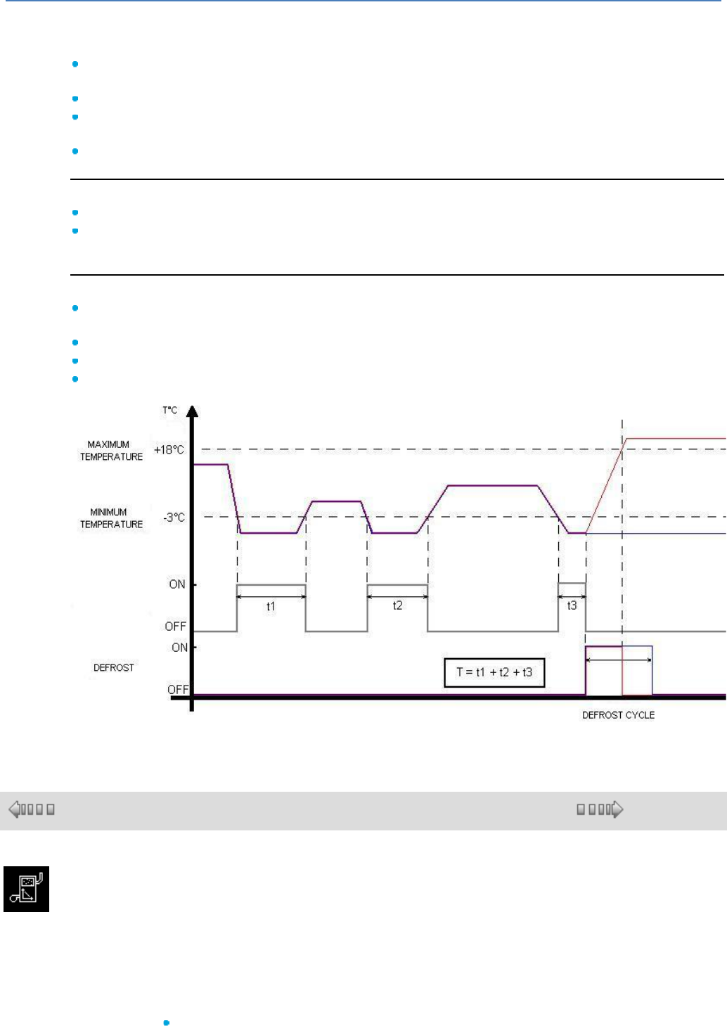
em4 soft Online Help
117
reverts to OFF even if it has not finished. This output can be triggered and stopped by means of the
corresponding inputs.
Inputs:
VALIDATION : Enables the function. If this input is not activated, the function remains inactive.
Activated implicitly if it has not been connected.
TEMPERATURE : Air temperature in °C*100 (-32768°C to 32767°C).
MANUAL DEFROST ON : Sets the defrost output to ON if the temperature is less than the maximum
temperature.
MANUAL DEFROST OFF : Sets the defrost output to OFF (Priority stop).
Outputs:
DEFROST : The defrost output is at ON when the CUMULATIVE OPERATING TIME has elapsed.
CUMULATIVE TIME : Measured duration, in minutes, when the temperature is less than the minimum
temperature or duration of the current defrost cycle.
Parameters:
CUMULATIVE OPERATING TIME : Time T, in minutes, at the end of which the function triggers
defrosting (1 to 32767).
DEFROST CYCLE : Duration of defrosting in minutes (1 to 32767).
MAXIMUM TEMPERATURE : Temperature in °C above which defrosting is stopped (10°C ... 20°C).
MINIMUM TEMPERATURE : Temperature in °C below which the time T is measured (-10°C ... 0°C).
1.4.2.5.14 HEAT CURVE
( § 1.4.2.5.13 )
( § 1.4.2.5.15 )
This function is used to modulate the heating water temperature according to the
atmospheric conditions. The function uses automatic regulation depending on the
temperature outdoors called the temperature curve or "water ratio". For every
variation in the outdoor temperature, the regulation automatically adjusts the heating
temperature according to the temperature curve. This makes it possible to always
have the right heating temperature with optimum efficiency.
Start time optimization:
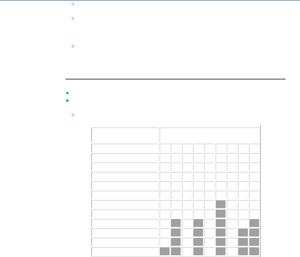
em4 soft Online Help
118
The aim is to optimize the precise moment when the boiler should start up in
the morning to change from the night-time temperature to that for daytime.
The first time, it is estimated that it will take 2 hours to change from 17°C (night)
to 20°C (day), therefore in order to have 20°C at 8 o'clock in the morning, the
function will take account of the day setpoint at [8 hours (daytime temperature
hour input) – 2 hours] = 6 o'clock in the morning.
If the "start time optimization" box is checked, in this example at 6 o'clock in the
morning, this starts a timer in minutes which will stop once the setpoint
temperature is reached. This value replaces the 2 hours previously in memory
and can be used to find out the installation slope in °C/min.
Inputs :
VALIDATION : regulation activated if the VALIDATION input is ON.
STANDARD OUTDOOR T°C : : daytime outdoor temperature which on average
will only fail to be achieved on one day a year. Enter 810 for 8.10°C.
Example for France :
Zone
Altitude band in meters
A
B
C
D
E
F
G
H
I
0 to 200
-2
-4
-5
-7
-8
-9
-10
-12
-15
201 to 400
-4
-5
-6
-8
-9
-10
-11
-13
-15
401 to 600
-6
-6
-7
-9
-11
-11
-13
-15
-19
601 to 800
-8
-7
-8
-11
-13
-12
-14
-17
-21
801 to 1000
-10
-8
-9
-13
-15
-13
-17
-19
-23
1001 to 1200
-12
-9
-10
-14
-17
-19
-21
-24
1201 to 1400
-14
-10
-11
-15
-19
-21
-23
-25
1401 to 1600
-16
-12
-21
-23
-24
1601 to 1800
-18
-13
-23
-24
1801 to 2000
-20
-14
-25
-25
2001 to 2200
-15
-27
-29

em4 soft Online Help
119
MAXIMUM WATER T° : maximum water temperature for which the size of the
heating installation has been determined in order to ensure comfort at the
"standard outdoor temperature". Enter 7000 for 70.00°C.
NON-HEATING OUTDOOR T° : temperature above which it is no longer
necessary to have the heating on. Enter 1500 for 15.00°C.
MINIMUM WATER T° : when the temperature outdoors equals the "non-heating
outdoor temperature" the water temperature reaches a minimum temperature.
Enter 3000 for 30.00°C.
DAY SETPOINT : desired indoor temperature during the day. Enter 2000 for
20.00°C.
NIGHT SETPOINT : desired indoor temperature at night. Enter 1700 for 17.00°C.
OUTDOOR SENSOR T° : temperature used when calculating the "outdoor delta"
which can be used to obtain the optimum water temperature for heating.
Example: 1015 corresponds to 10.15°C.
WATER SENSOR T° : water temperature feedback used for regulation. Example:
1015 corresponds to 10.15°C.
INDOOR SENSOR PRESENCE: activation of compensation with ambient
temperature sensor.
INDOOR SENSOR T° : activation of compensation with ambient temperature
sensor. Example: 2015 corresponds to 20.15°C.
DAYTIME TEMPERATURE HOUR : hour corresponding to the start of regulation
according to the day setpoint. Enter 8 for 08.00.
NIGHT-TIME TEMPERATURE HOUR : hour corresponding to the start of
regulation according to the night setpoint. Enter 22 for 22.00.
Outputs :
HEATING : heating control, if set to ON, heating is on, if set to OFF heating is not
on.
OFFSET : time corresponding to the start time optimization in minutes.
HYSTERESIS : used to avoid the output jumping around the setpoint value (0 ≤
em4 soft Online Help
120
hysteresis ≤ 25°C) (modifiable via the display).
Parameters :
HYSTERESIS : used to avoid the output jumping around the setpoint value (0 ≤
hysteresis ≤ 25°C) (modifiable via the display).
MIN TIME BEFORE RESTART : period during which the output cannot be
changed to ON. This timer is triggered each time the HEATING output changes to
OFF.
START TIME OPTIMIZATION : if this box is checked, the function calculates the
heating time needed to reach the setpoint when changing from night-time -->
daytime.
1.4.2.5.15 PID AUTO-TUNING
( §
1.4.2.5.14 )
( § 1.4.2.6 )
This function is an auto-tuning proportional-integral-derivative (PID) controller.
Inputs:
VALIDATION : Digital input. The function remains inactive while the input is inactive. However, it
is implicitly active if the input is not connected.
CURRENT VALUE : 16-bit input which can be used to acquire the value to be controlled
(indicated by the sensor).
ENABLE_AUTO-TUNING : Digital input. Auto-tuning is initiated when the function detects a
pulse on this input. The input is inactive when it is not connected.
This method is applicable only when the system is around an operating point and able to
oscillate.
GAIN (Kp) : Proportional gain. The proportional part of PID control constitutes the most
elementary form of feedback, where the command signal is simply the difference between the
setpoint and the value to be controlled, multiplied by the gain Kp. Intuition tells us that by
increasing this gain, the command signal acts on the system more strongly and thus reduces the
difference faster. However, an excessively large proportional gain will give rise to oscillatory
behaviour, resulting in a reduction or even loss of stability.
Ti Integral time. In the case of a proportional controller, the appearance of a command signal
that is not zero means that it is subject to the existence of a discrepancy between the setpoint
and the value to be controlled. The use of this command therefore usually causes quadrature
droop. This is eliminated by using the integral term. This generates, from even the slightest
constant sign error signal, a command whose amplitude never stops growing. The consequence
of this will be to cancel out any permanent discrepancy. The downside is the destabilising effect
it may cause.
Td : Derivative time. When, at a given time, the measured error increases, it is logical to assume
that, at a later time, it will be even greater. The idea of the derivative term is therefore to predict
the future error so as to be able to correct it directly, without waiting for it to appear. A
proportional-derivative controller can be interpreted as a proportional correction affecting the
predicted error, where the prediction is made by adding its derivative term weighted by the Td
factor to the momentary discrepancy (linear extrapolation).
VALID PARAMS Kp, Ti, Td : Digital input. The Kp, Ti, Td parameter inputs are loaded in the
controller on every cycle when this input is active.
PRESET VALUE : Input with 16 signed bits which can be used to fix the regulation setpoint.
Outputs:
ANA/PWM OUTPUT : This is an analog output that can be connected to a 0-10 V analog output
FB (0 - 1000) or a PWM FB (0 - 100). This is the OUTPUT of a proportional-integral-derivative
(PID) controller whose parameters can be modified or auto-tuned. It is the command destined

em4 soft Online Help
121
for the input of the system to be controlled.
Kp, Ti, Td : Output parameters which can be modified from a display screen.
STATE : This output indicates the controller operating phase; its states range from 0 to 6.
STATE 0 : Inactive state or controller not enabled.
STATE 1 : Setpoint tracking.
STATE 2 : Setpoint reached (State desired by regulation; the purpose of regulation).
STATE 3 : Initialisation of auto-tuning or tracking the operating point.
STATE 4, 5, 6 : Auto-tuning or parameter search stages.
Parameters:
RESPONSE TIME : This is the time it takes the system to reach a static value when it is
energized by a step (see diagram). It is used to initialise (approximately) those parameters for
starting regulation. It is advisable to perform auto-tuning after any initialization other than
"MANUAL".
Kp, Ti, Td : These parameters are taken into account when the function starts if parameter
initialisation is in "MANUAL" mode.
ACTION : This parameter is used to select the the direction of the output action. Example of a
thermal system: In Heat mode, the OUTPUT must increase so that the temperature reaches a
setpoint higher than the current temperature. This is the default mode for controlling radiator
type systems. In Cool mode, the logic is reversed. The more the OUTPUT increases, the more
the value of the temperature acquired as a feedback decreases. This is the mode used to
control refrigerator type systems. This parameter should be defined according to the system
controlled. Incorrect parameter setting can cause a discrepancy in the temperature..
ANA/PWM OUTPUT: sets the output as 0 - 1000 or 0 - 100.
Ti/T : This is the ratio between the integral time (Ti) and the sampling period (T). It is between
10 and 100. It is used to set the sampling period indirectly.
Parameter setting:
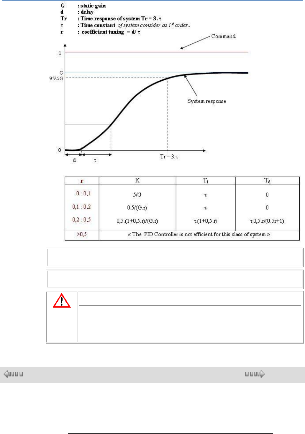
em4 soft Online Help
122
Note : The PID controller parameters can be modified online via the display function. These
modifications are instantly taken into account in the next cycle.
Note : The sampling period is calculated automatically using the integral time Ti and the ratio
Ti/T; the minimum value of T is 0.1 s.
CAUTION
When you apply the new values of Kp, Ti, Td, you should re-check the state of your
equipment so as to be forewarned of any damage which might be due to unwanted
transients.
Failure to follow this instruction can result in serious injury or equipment
damage.
1.4.2.6 PROG Functions : Programmation
( § 1.4.2.5.15 )
( § 1.4.2.6.1 )
At a Glance
Subject of this Section
This section describes the different PROG functions available using FBD
language.
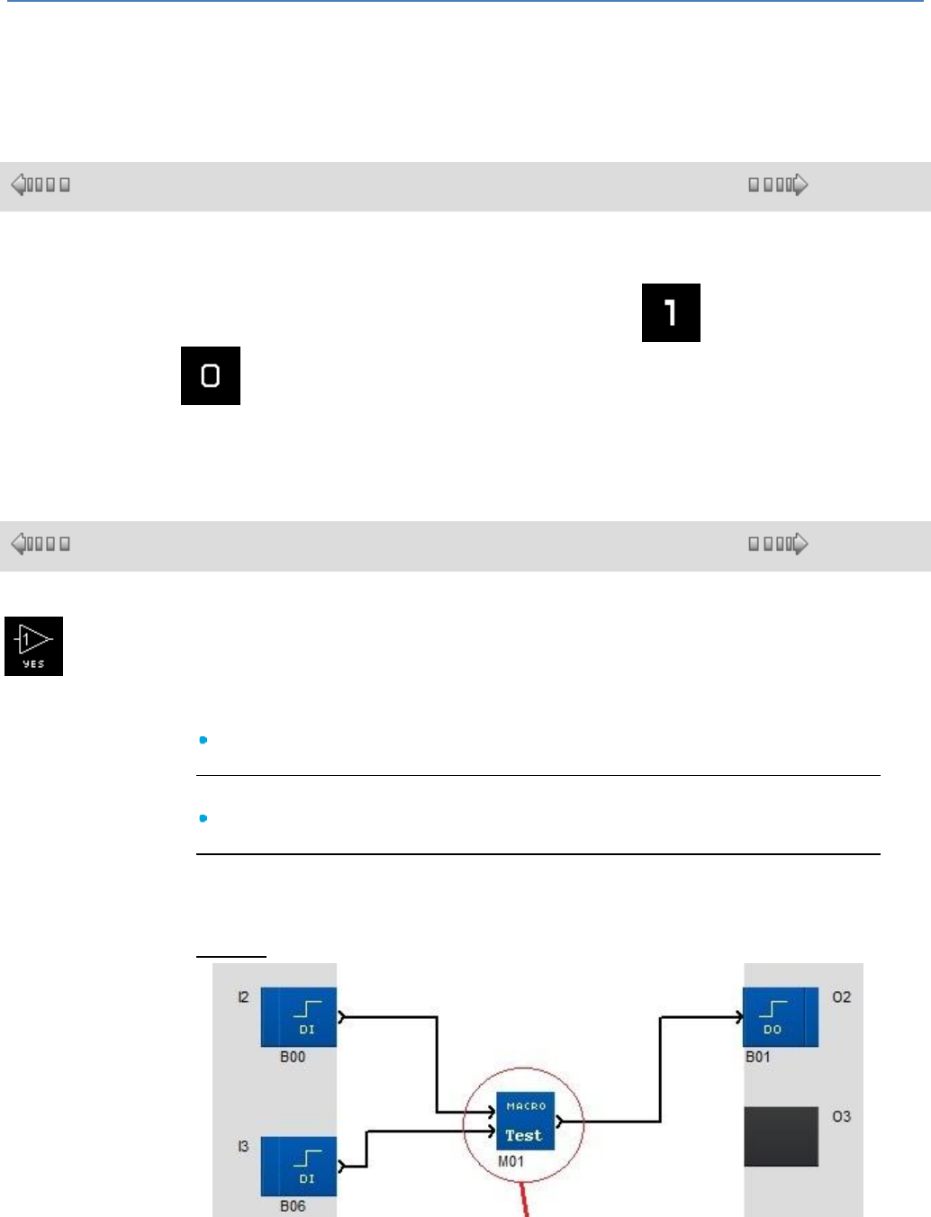
em4 soft Online Help
123
What's in this Section?
This section contains the following topics:
Numerical value, latching, management of time, status, etc.
1.4.2.6.1 Level 1, Level 0
( § 1.4.2.6 )
( § 1.4.2.6.2 )
Discrete Constant-Type Inputs
There are two types of Discrete constants: the 1 constant and the 0 constant
. These two constants can be used to set the function inputs to 1 or 0.
In Simulation or Debugging modes it is possible to force these inputs in the reverse
order. The symbol then appears in orange...
1.4.2.6.2 YES
( § 1.4.2.6.1 )
( § 1.4.2.6.3 )
This function can be used to copy the input to the output.
Input:
Digital input.
Output:
Digital output.
Operation:
This is very helpful when macros are being used, to be able to connect an input to
several blocks.
Example
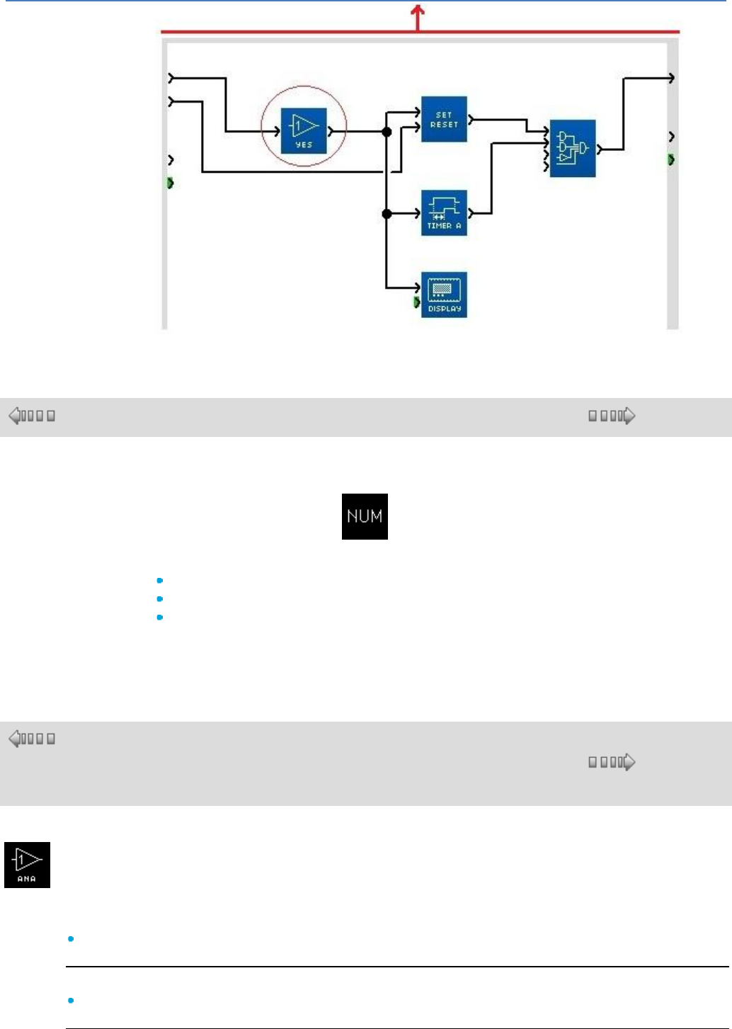
em4 soft Online Help
124
1.4.2.6.3 NUM Numerical Value
( § 1.4.2.6.2 )
( § 1.4.2.6.4 )
Numerical Constant-Type Inputs
The numerical constant NUM is an integer with a value between -32768
and +32767.
This constant can be used to set values to the functions' non-connected inputs:
GAIN,
COMP IN ZONE,
TRIGGER.
The value of the constant can be set in the Parameters window.
In Simulation or Debugging modes it is possible to modify the constant.
1.4.2.6.4 YES NUM
( §
1.4.2.6.
3 )
( § 1.4.2.6.5 )
This function can be used to copy the input to the output.
Input:
NUM input.
Output:
NUM output.
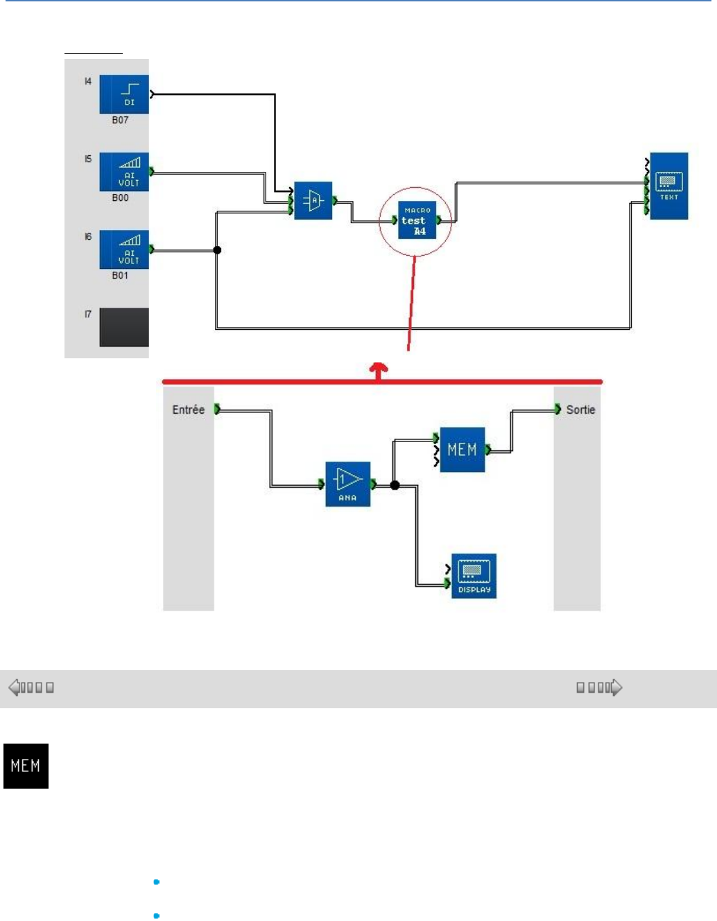
em4 soft Online Help
125
Operation:
This is very helpful when macros are being used, to be able to connect an input to several blocks.
Example:
1.4.2.6.5 MEMORIZING 1 value (MEM)
( § 1.4.2.6.4 )
( § 1.4.2.6.6 )
This function is used to save a value between -32768 and 32767
The value stored in the function is permanently available on OUTPUT.
On power-up, the saved value depends on the option chosen in the "parameters"
window:
If Save on power break is at NO, then the saved value at the time of the last
power break is deleted and replaced with 0.
If Save on power break is at YES, then the saved value at the time of the last
power break is unchanged.
When the MEMORIZING input changes from 0 to 1, the saved value is deleted
and replaced with the new value present on INPUT at this moment.
This value remains frozen, regardless of any INPUT variations, until the next time
MEMORIZING changes from 0 to 1.

em4 soft Online Help
126
When the MEMORIZING input returns to 0, the value is still saved.
When the RESET TO ZERO input changes from 0 to 1, the saved value is deleted
and replaced with 0. This input has priority over MEMORIZING
As long as the RESET TO ZERO input remains at 1, the saved value remains at 0
regardless of the MEMORIZING states or transitions
When the RESET TO ZERO input returns to 0, the saved value remains at zero
until the next MEMORIZING transition.
1.4.2.6.6 STORAGE : 8 storage values
( § 1.4.2.6.5 )
( § 1.4.2.6.7 )
This function calculates a sliding average on values stored in the memory.
On starting up the application, the FB STORAGE function block is active by default.
When rising edge appears at input VALIDATION, the byte value present on the input
VALUE is stored.
This value can be read on the MEMORY_1 output. At this point, when there is only
one value in the memory, the average value read on the output AVERAGE is
identical to the MEMORY_1 value.
At the 2nd rising edge at the input VALIDATION, the byte value present on the input
VALUE is stored in the MEMORY_2 output. The average value read on the output
AVERAGE is equal to the value (MEMORY_1 + MEMORY_2) / INDEX and so on up
to MEMORY_8. The INDEX output counts the number of values stored in the
memory. Once 8 values have been stored, the next rising edge at input
VALIDATION shift all values, MEMORY_8 replaces MEMORY_7, the new value is
stored in the space freed in MEMORY_8 and all the bytes stored are shift by one
MEMORY_7 to MEMORY_6 and so on down to MEMORY_1. The value previously
stored in MEMORY_1 before the new capture is lost. The AVERAGE value is
recalculated.
The integer value of the calculated mean is truncated. A pulse at the input RAZ
resets all values stored to zero, including the AVERAGE and the INDEX.
ENTREES :
VALIDATION : DISC. When rising C_ON , this store in memory.
RESET : DISC. When rising C_ON, all outputs are reset to zero.
VALUE : S16. Value to be stored in the memory.
OUTPUTS :
MEMORY_1 : S16. 1st value stored in the memory.
MEMORY_2 : S16. 2nd value stored in the memory.
MEMORY_3 : S16. 3rd value stored in the memory.
MEMORY_4 : S16. 4th value stored in the memory.
MEMORY_5 : S16. 5th value stored in the memory.
MEMORY_6 : S16. 6th value stored in the memory.
MEMORY_7 : S16. 7th value stored in the memory.
MEMORY_8 : S16. 8th value stored in the memory.
AVERAGE : S16. Average value.
INDEX : S16. Number of values stored in memory.
MAX : S16. Maximum of the values stored in memory.
MIN : S16. Minimum of the values stored in memory.
em4 soft Online Help
127
1.4.2.6.7 ARCHIVE : 2 storage values
( § 1.4.2.6.6 )
( § 1.4.2.6.8 )
Overview
The ARCHIVE data archiving function enables two values to be saved
simultaneously with their date-stamping information.
Access
The ARCHIVE function is accessible from the PROG function bar.
Inputs/Outputs
Description of the inputs:
LATCHING: This is the archive function command input (Discrete( § 1.4.2.1.1 )
type) on each rising edge (transition from inactive to active), the VALUE input is
memorized.
If this input is not connected, then it is set to inactive.
RESET: When this input (Discrete( § 1.4.2.1.1 ) type) is active, it forces the
VALID ARCHIVE to inactive: previously saved values are still available.
If this input is not connected, then it is set to inactive.
ARCHIVE VALUE 1: this is the first input that is saved. The whole value present
on this input is saved with its date-stamping information: time and date (all of this
information is available on the outputs).
If this input is not connected, then it is set to inactive.
ARCHIVE VALUE 2: second input saved
If this input is not connected, then it is set to inactive.
Description of the outputs:
VALID ARCHIVE: this output (Discrete( § 1.4.2.2.1 ) type) indicates the validity
of the storage in process:
Inactive: no data available
Active: data available
MINUTE: minute value of the date-stamping information (0 to 59) (INTEGER
type)
HOUR: hour value (0 to 23) (INTEGER type)
DAY: day value (1 to 31) (INTEGER type)
MONTH: month value (1 to 12) (INTEGER type)
YEAR: year value (0 to 99) (INTEGER type)
ARCHIVE 1: whole value present on the VALUE 1 input (INTEGER type)
ARCHIVE 2: whole value present on the VALUE 2 input (INTEGER type)
Parameters
From the programming workshop
When selected, the Save on power failure parameter enables the current value of
the counter to be retrieved following a power failure( § 1.2.20 ).
Storage Mechanism
If the LATCHING input is activated several times, only the data concerning the last
activation is memorized.
Display of Saved Values
Saved values can be displayed; in order to do this, simply connect the outputs of
the ARCHIVE function to the DISPLAY blocks.
The DISPLAY function can modify the displayed value if the Modification
authorized parameter is checked.
em4 soft Online Help
128
Note: Any modification risks damaging the consistency of the archived data:
VALUE/DATE.
1.4.2.6.8 RANDOM
( § 1.4.2.6.7 )
( § 1.4.2.6.9 )
This function provides a pseudo-random value between the minimum and
maximum values set by the user. The user chooses the time at which the value
needs to appear as an output.
Inputs:
VALIDATION : Enables the function. If this input is not activated, the function
remains inactive. Activated implicitly if it has not been connected.
TRIGGER : Its rising edge allows a pseudo-random value to be displayed as an
output.
Outputs:
VALUE PULSE : This output sends a pulse when a new pseudo-random value is
displayed as a Value output.
VALUE : Pseudo-Random value (from -32767 to 32767).
Parameters:
CYCLE(S) : Number of cycles defined as trigger period (from 2 to 32767).
0,1s : Number of tenths of seconds defined as trigger period (from 1 to 32767).
1s : Number of seconds defined as trigger period (from 1 to 32767).
INPUT : Trigger option via the function TRIGGER input.
MAX VALUE : Maximum value permitted as an output (from -32767 to 32767).
MIN VALUE : Minimum value permitted as an output (from -32768 to 32766).
1.4.2.6.9 HOUR MINUTE
( § 1.4.2.6.8 )
( § 1.4.2.6.10 )
This function provides the controller hour and minutes.
Outputs:
HOUR: Value of the controller hour (0 to 23)
MINUTE: Value of the controller minute (0 to 59)
1.4.2.6.10 HOUR MINUTE Conversion
( § 1.4.2.6.9 )
( § 1.4.2.6.11 )
em4 soft Online Help
129
This function is used to convert a time period in the "hour : minute" format to
minutes and vice versa.
Inputs:
"Hour : Minute" : represents the time period in "hour : minute" format to be
converted to minutes (0 to 32759).
Note : The format of this input must be as follows: value 1530 for 15.30.
Minute input : Represents the time period in minutes to be converted to "hour
: minute" format (0 to 19679).
Note : If one of the input values is negative, its corresponding output is set to
0.
Outputs:
Minute output : Represents the result of the conversion into minutes (0 to
19679).
"Hour : Minute" output : Represents the result of the conversion into "hour :
minute" format (0 to 32759).
1.4.2.6.11 Controller STATUS
( § 1.4.2.6.10 )
( § 1.4.2.6.12 )
Description
This function allows the user to access the controller status and modify the
behavior of its FBD and/or SFC program according to particular states.
Only an alarm status is available (the warning can be retrieved by the application),
as the error causes the application to switch OFF and the status function block is
therefore no longer executed.
Access
The function is accessible from the PROG function bar.
Inputs/Outputs
This function block does not have an input.
The function has seven outputs:
ALARM STATUS: Active as soon as an alarm( § 1.6.1.12 ) (warning) is
detected in the controller. In this case, the corresponding code is available on
the ALARM NUMBER output. The only way to return this output to inactive
status and set the ALARM NUMBER to zero is to use the front panel FAULT
menu with the CLEAR and YES commands. Usage: Allows the user program to
be put into a known "fallback" state in the event of a fault.
DEBUGGING ON: Active when the user program is correctly executed on the
controller and a Monitoring session is activated from the programming
workshop.
Otherwise, this output is inactive.
Usage: In this operating mode, the watchdog action in the configuration is
systematically deleted regardless of the programmer's initial choice. If in the user
program, the watchdog action (error/warning) is essential, this output allows the
user program to be put into a known state with no consequences (making no
changes) for the outputs controlled.
em4 soft Online Help
130
PARAMETERS ON: Sends a pulse when the user program is correctly executed
on the controller and a parameters modification action is activated either from
the programming workshop, or after execution in the PARAMETER menu on the
front panel of the LCD.
Otherwise, this output is inactive.
Usage: In this operating mode, the watchdog action in the configuration is
systematically deleted regardless of the programmer's initial choice. If, in the
user program, the watchdog action (error/warning) is essential, this output allows
the user program to be put into a known state with no consequences (making no
changes) for the outputs controlled.
COLD START: Sends a pulse during the first execution cycle of a user program
when it switches from OFF to ON (new application, loss of context, etc.). All the
variables are reset.
COLD START corresponds to a change from OFF to ON with Reset.
Usage: This pulse allows the programmer to insert specific initializations in his
program, for example, initializing the SFC "RESET-INIT" function, which confers
saving on a power failure in the SFC chart containing it.
WARM START: Sends a pulse during the first execution cycle of a user program
when power is restored following a power failure occurring when the program
was in RUN mode.
WARM START is triggered by the end of a mains power failure simulation or ON
without Reset.
Usage: This pulse lets the programmer insert specific initializations in his
program once the power has been restored.
FLASH CYCLE: Delivers a periodic signal that switches alternately from ON to
OFF at each execution of the user program (RUN mode). Its period is equal to
twice the duration of the execution period described in the configuration,
ALARM NUMBER: Provides the alarm code in signed integer format when the
ALARM STATUS output is active.
1.4.2.6.12 SUMMER/WINTER time
( § 1.4.2.6.11 )
( § 1.4.2.7 )
Summer Time Input
The summer time input function is active throughout summer time, and
inactive throughout winter time .
Note: To confirm this function:
display the Program
configuration window:
menu:
File/Properties,
or by selecting the "program" button",
select the Date format
tab,
check the Activate the
summer/winter time
change box,
define the dates when
the time change takes
place:
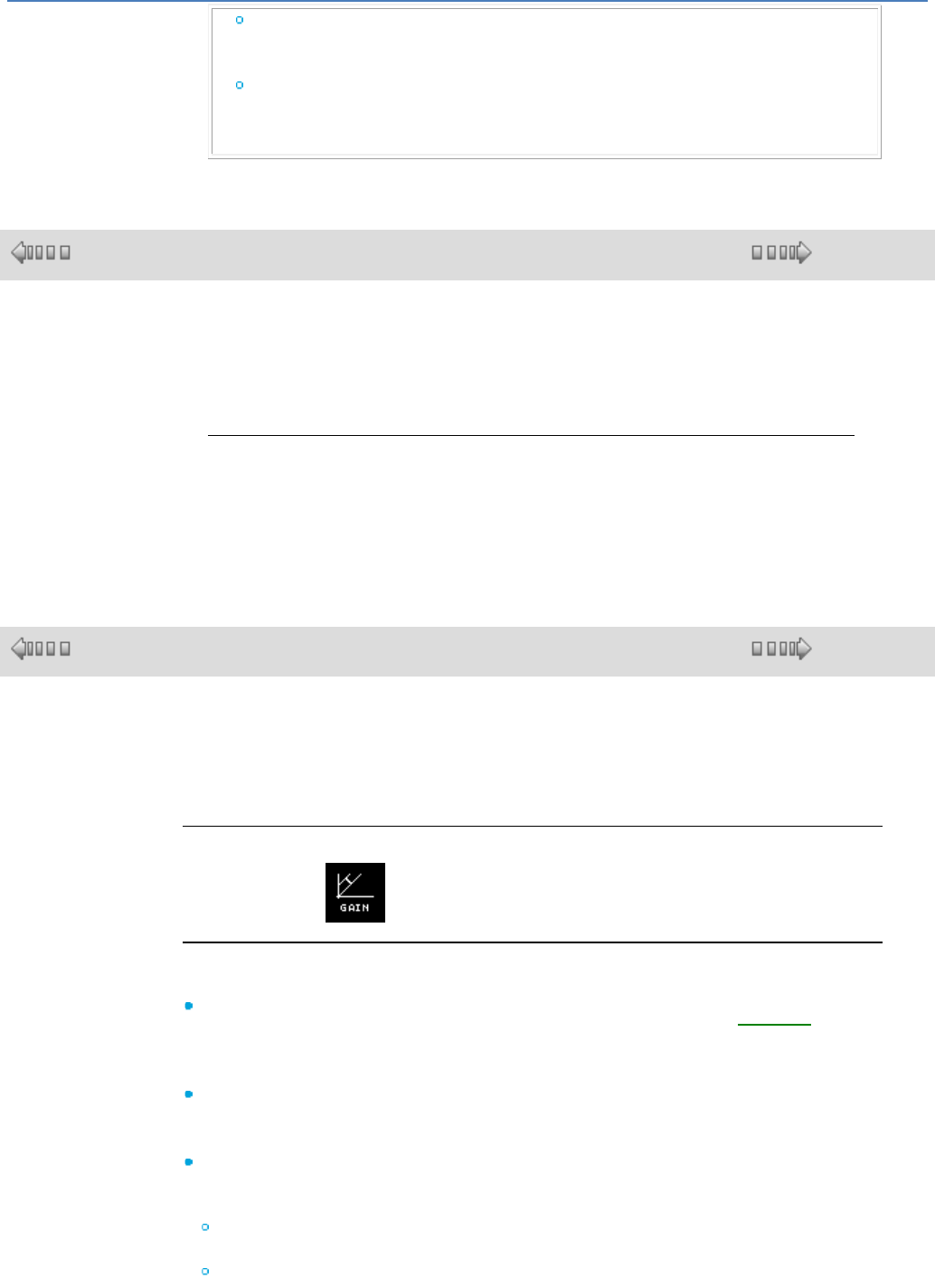
em4 soft Online Help
131
Either using one of the
preset geographic
zones,
Or by manually
configuring the date
(month/Sunday).
1.4.2.7 CALC Functions : Calculation
( § 1.4.2.6.12 )
( § 1.4.2.7.1 )
At a Glance
Subject of this Section
This section describes the different CALC functions available using FBD
language.
What's in this Section?
This section contains the following topics:
Gain, maths operations, multiplexer, demultiplexer, decimal & binary
conversions, register, table from a spreadsheet, etc.
1.4.2.7.1 GAIN Function
( § 1.4.2.7 )
( § 1.4.2.7.2 )
Description
The Gain function enables analog values to be converted by changing the scale and
offset.
Gain calculation formula: y = a/bx + c
Access
The gain function is accessible from the CALC function bar.
Inputs/Outputs
Description of the inputs:
ENABLE FUNCTION: gain function input command, whose type is Discrete( §
1.4.2.1.1 ).
The state of this input determines operation of the block: if the ENABLE FUNCTION
input is inactive, the CALCULATION OUTPUT retains the last calculated value.
CALCULATION INPUT: value of the analog input connected to the gain function.
This is an integer between -32768 and 32767.
Description of the output:
CALCULATION OUTPUT: output value of the gain function.
This value depends upon the state of the ENABLE FUNCTION input.
If the ENABLE FUNCTION input is:
inactive, then the CALCULATION OUTPUT equals the last calculated value, when
the ENABLE FUNCTION input is inactive,
active, then the CALCULATION OUTPUT is equal to the result of the gain
calculation formula.
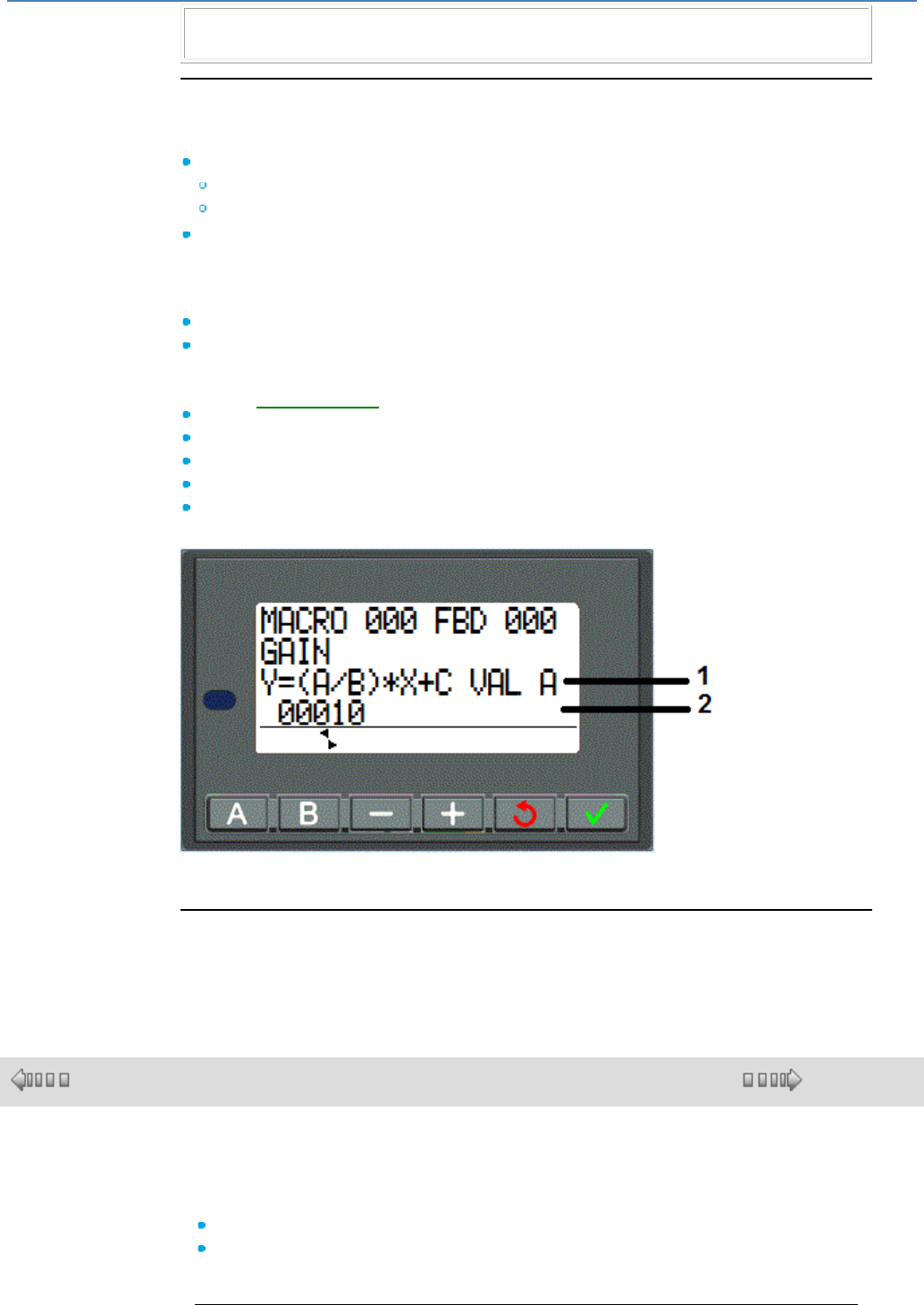
em4 soft Online Help
132
Note: if the ENABLE FUNCTION input is not connected, then it is considered to be
active.
Parameters
In the programming software
From the Parameters window, you can adjust:
A/B which corresponds to the gain applied by the function with:
A: being a numerator (from -32768 to 32767),
B: denominator (from -32768 to -1 and from 1 to 32767)
C which is the offset applied by the function, and is an integer between -32768 and
32767.
In addition, it is possible to define an operating range by setting limits for the function
output:
Lower limit: integers between -32768 and 32767,
Upper limit: integers between -32768 and 32767.
From the front panel
From the PARAMETER( § 1.3.2 ) menu, you can set the parameter values:
A: gain numerator
B: gain denominator (value 0 prohibited),
C: offset,
upper limit,
lower limit.
Illustration:
1
Name of the parameter displayed
2
Value of the parameter displayed
Parameter Modification
To modify the parameters from the front panel of the controller, check the Authorized
modification box of the Parameters window.
1.4.2.7.2 ADD-SUB Arithmetic Function
( § 1.4.2.7.1 )
( § 1.4.2.7.3 )
Description
The ADD-SUB Addition and/or Subtraction function enables simple operations to
be carried out on integers:
Addition,
Subtraction.
Calculation formula: Out = I1 + I2 - I3
em4 soft Online Help
133
Access
The ADD-SUB function is accessible from the CALC function bar.
Inputs/Outputs
Description of the inputs:
INPUT 1: first input value of the formula (integer( § 1.1.1 )),
INPUT 2: second input value of the formula (integer( § 1.1.1 )),
INPUT 3: third input value of the formula (integer( § 1.1.1 )).
Note: If the INPUTS are not connected, they are set to 0.
ERROR PROPAGATION: this input, whose type is Discrete( § 1.1.1 ), is used to
propagate errors (or saturations) from calculation functions (ADD-SUB or MUL-
DIV) carried out upstream.
Note: If ERROR PROPAGATION is at 1, then the operations are not performed
and the ERROR/OVERRUN output is set to 1.
Note: If ERROR PROPAGATION is not connected, it is set to 0.
Description of the outputs:
CALCULATION OUTPUT: this is the value of the calculation formula output
(integer( § 1.1.1 )).
ERROR/OVERRUN: this output, whose type is Discrete( § 1.1.1 ), indicates any
presence of saturation errors).
This output is activated in the following cases.
The consequence of the operations is a result that is not included in the
interval [-32768, +32767],
The ERROR PROPAGATION input is active.
Examples
Simple addition: simply do not use the INPUT 3 input.
Simple subtraction: simply do not use one of the INPUT 1 or 2 inputs.
1.4.2.7.3 MUL-DIV Arithmetic Function
( § 1.4.2.7.2 )
( § 1.4.2.7.4 )
Description
The MUL-DIV Multiplication and/or Division function enables simple operations to
be carried out on integers:
Multiplication,
Division.
Calculation formula: Out = I1 * I2 / I3
Access
The MUL-DIV function is accessible from the CALC function bar.
Inputs/Outputs
Description of the inputs:
INPUT 1: first input value of the formula (integer( § 1.1.1 )).
INPUT 2: second input value of the formula (integer( § 1.1.1 ))
INPUT 3: third input value of the formula (integer( § 1.1.1 ))
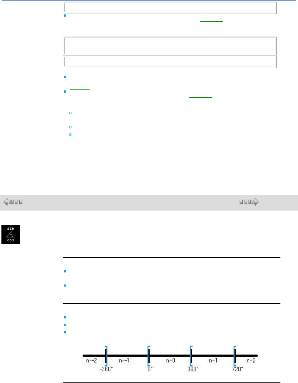
em4 soft Online Help
134
Note: If the INPUTS are not connected, they are set to 1.
ERROR PROPAGATION: this input, whose type is Discrete( § 1.1.1 ), is used to
propagate errors (or saturations) from calculation functions (ADD-SUB or MUL-
DIV) carried out upstream.
Note: If ERROR PROPAGATION is at 1, then the operations are not performed
and the ERROR/OVERRUN output is set to 1.
Note: If ERROR PROPAGATION is not connected, it is set to 0.
Description of the outputs:
CALCULATION OUTPUT: this is the value of the calculation formula output
(integer( § 1.1.1 )).
ERROR/OVERRUN: this output, whose type is Discrete( § 1.1.1 ), indicates any
presence of saturation errors).
This output is activated in the following cases:
The consequence of the operations is a result that is not included in the
interval [-32768, +32767],
The ERROR PROPAGATION input is active,
The INPUT 3 equals 0.
Examples
Simple multiplication: simply do not use the INPUT 3 input.
Simple division: simply do not use one of the INPUT 1 or 2 inputs.
1.4.2.7.4 SIN COS
( § 1.4.2.7.3 )
( § 1.4.2.7.5 )
This function is used to calculate the cos and sin of an angle.
Inputs:
Validation : Function validation input. Until this input is activated, the function
remains inert. Validation is active implicitly if it has not been connected.
Angle : Represents the angle in degrees. Its value must be between -32768 and
32767 for an angle between -3276.8° and 3276.7° (900 = 90°).
Outputs:
Sin : Result of ("Angle" sin) x 10000.
Cos : Result of ("Angle" cos) x 10000.
Revolution : Revolution number -10<= n <= 9
Performance:
The function calculates the cos and the sin to the nearest 0.0001 by rounding up or
down as appropriate.
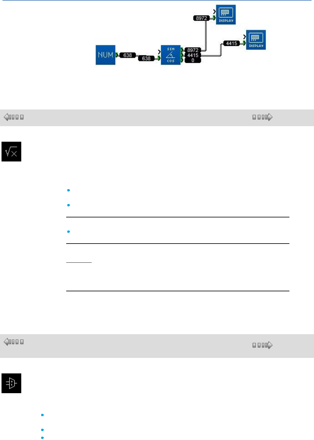
em4 soft Online Help
135
Sin (63°8) = 0.8972 and Cos (63°8) = 0.4415.
1.4.2.7.5 SQUARE ROOT
( § 1.4.2.7.4 )
( § 1.4.2.7.6 )
This function is used to calculate the square root of the number present as an input
with accuracy to two decimal points.
Inputs:
VALIDATION : Function validation input. Until this input is activated, the function
remains inert. Validation is active implicitly if it has not been connected.
CALCULATION input : The value must be between 0 and 32767.
Outputs:
CALCULATION output : The result is presented in the format "Root" x 100.
Operation:
Example:
For X = 20000 => Root of X = 141.42. The value read as an output of the function
is 14142.
If used as an input, the number is negative and the result is 0.
Performance:
The calculation is accurate to 0.01 either way.
1.4.2.7.6 BIT MULTIPLEXER with 2 input channels
( §
1.4.2.7.5 )
( § 1.4.2.7.7 )
This function is used to copy the selected input to the outputs Q and /Q.
Inputs:
VALIDATION : Function validation input. Until this input is activated, the function remains inert.
Validation is active implicitly if it has not been connected.
Channel A.
Channel B.
em4 soft Online Help
136
SELECTION : Used to choose the input to be copied as an output.
Outputs:
Output Q : Retranscribes the selected input state.
Output /Q : Retranscribes the selected input complementary state.
Operation:
Truth table:
Validation
Channel A
Channel B
Selection
Q Output
/Q Output
0
X
X
X
0
0
1
0
X
0
0
1
1
1
X
0
1
0
1
X
0
1
0
1
1
X
1
1
1
0
1.4.2.7.7 BIT MULTIPLEXER with 10 input channels
( §
1.4.2.7.6
)
( § 1.4.2.7.8 )
This function is designed to pass on activation of the inputs to an output in a coded manner. For example,
it can be used to access a modem via its digital input in order to send SMS messages.
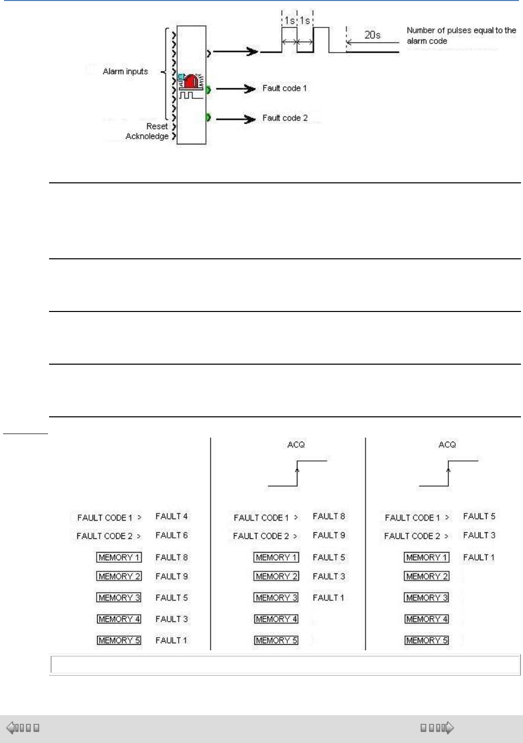
em4 soft Online Help
137
The function has 10 digital inputs for 10 possible faults within the application.
The digital output is used to send the fault code.
Encoding :
The digital output sends a number of pulses equal to the number of the activated input. If input 5 is
activated, 5 pulses will be generated at the output. The time at the top limit is one second, the same as at
the bottom limit. 20 blank seconds are left between two sets of pulses sent to ensure the modem works
correctly.
Storing faults :
The function processes 2 faults and stores up to 7 faults. The two "fault code" outputs represent the
codes (or numbers) of the first two inputs activated.
Reset input :
This input is used to reinitialize the function. The outputs are reset, no further pulses are sent and any
faults in the memory are cleared.
Acknowledge input :
This input is used to acknowledge the last 2 faults that appeared. On each rising edge detected on this
input, 2 faults stored on the "fault code" outputs are shifted in order of appearance.
Example :
Note : Non-connected inputs are at 0 by default.
1.4.2.7.8 MUX Analog Multiplexer with 2 Input Channels
( § 1.4.2.7.7 )
( § 1.4.2.7.9 )
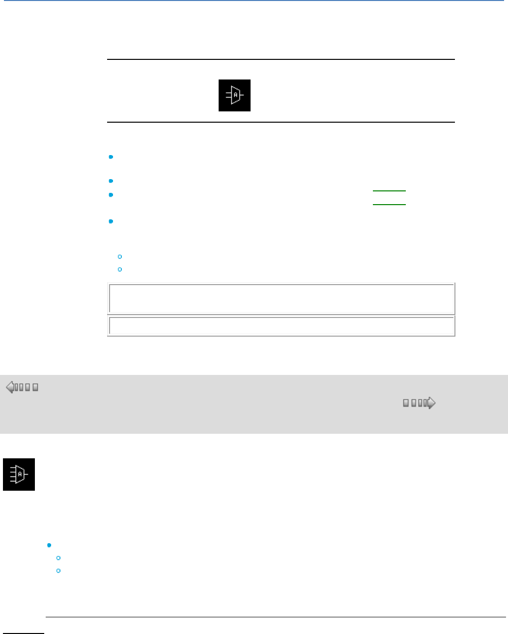
em4 soft Online Help
138
Description
The MUX function carries out two input channel multiplexing on the OUTPUT.
Access
The multiplexing function is accessible from the CALC function bar.
Inputs/Outputs
Description of the inputs:
SELECTION: this input is used to choose the input channel to apply to the
output.
CHANNEL A: this is the multiplexer input A, whose type is integer( § 1.1.1 ).
CHANNEL B: this is the multiplexer input B, whose type is integer( § 1.1.1 ).
Description of the output:
OUTPUT: this is the multiplexer output.
This value depends upon the state of the SELECTION input.
If the SELECTION input is:
inactive: the OUTPUT corresponds to CHANNEL A,
active: the OUTPUT corresponds to CHANNEL B.
Note: If the SELECTION input is not connected, then it is considered to be
inactive.
Note: If CHANNELS A or B are not connected, then they are set to 0.
1.4.2.7.9 MUX Analog Multiplexer with 4 Input Channels
( §
1.4.2.7.
8 )
( § 1.4.2.7.10 )
This function multiplexes the WORD inputs. It is used to route the value of one of the inputs selected by
the ADDRESS input to the output. The input is routed to the output on each rising edge of the
VALIDATION input.
The BASE ADDRESS parameter allows several blocks to be used at the same time to multiply inputs.
The Parameters tab contains :
BASE ADDRESS : Contains the address of the INPUT 1 input.
SAVE ON POWER BREAK : Chooses whether or not the function is reinitialised if the controller
power supply is disconnected.
When they are not connected, the digital input is in the OFF state and the WORD inputs contain 0.
Example:
When the BASE ADDRESS parameter contains the value 0 these inputs have addresses 0, 1, 2, 3
respectively, and in this case if the ADDRESS input equals 2 the VALUE of the third input will be copied
to the output.
If a second block is being used, 8 inputs can be demultiplexed by putting the value 4 as the BASE
ADDRESS in the second block and connecting the VALIDATION and ADDRESS inputs to the same
source.
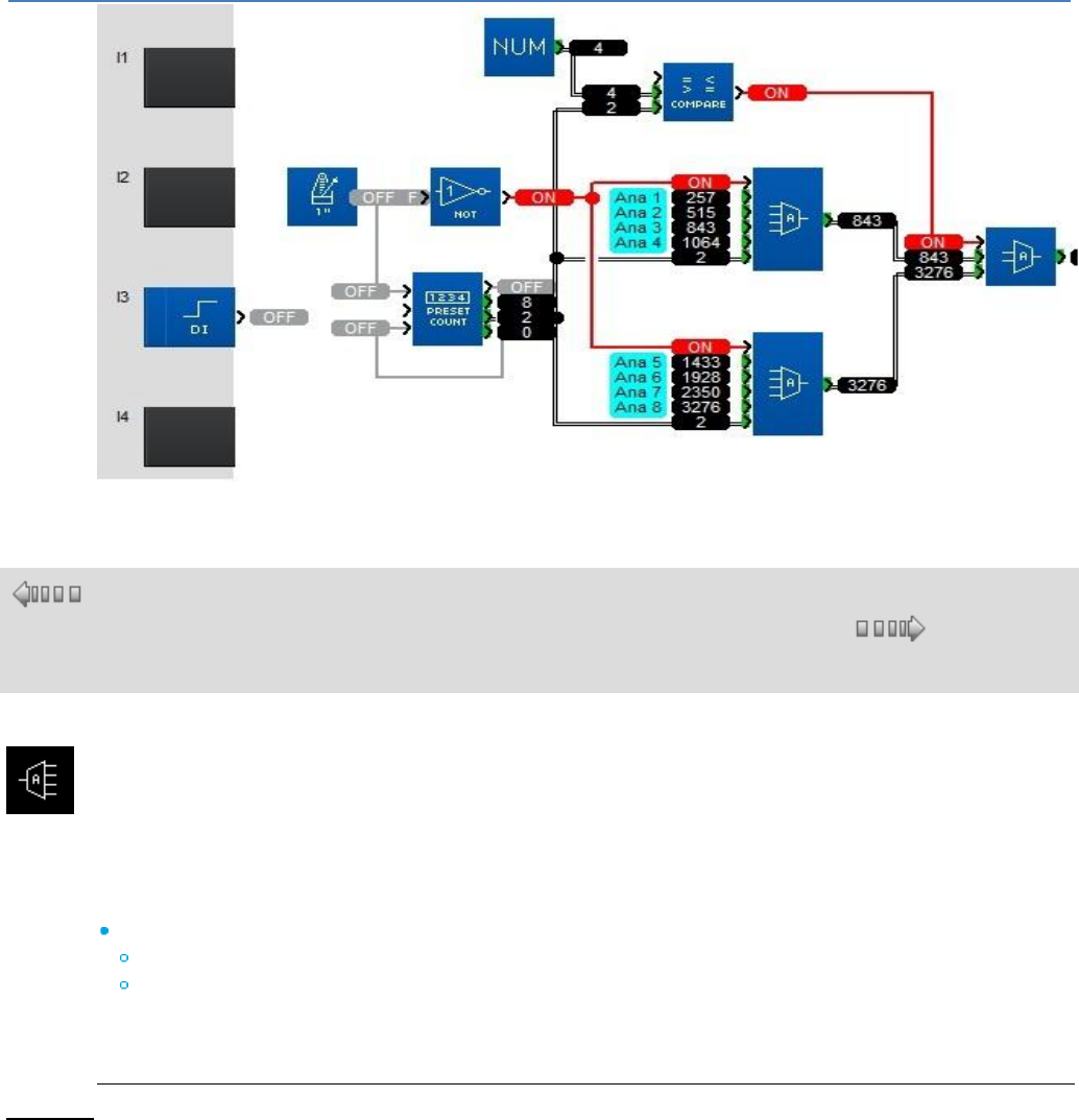
em4 soft Online Help
139
1.4.2.7.10 DEM Analog Demultiplexer with 4 Output Channels
( §
1.4.2.7.
9 )
( § 1.4.2.7.11 )
This function demultiplexes integers. It is used to route the input value onto one of the 4 OUTPUTS on
each rising edge of the VALIDATION input.
A VALUE copied to an output does not revert to 0 when a VALUE is written to another ADDRESS.
The BASE ADDRESS parameter allows several blocks to be used at the same time to multiply outputs.
The Parameters tab contains :
BASE ADDRESS : Contains the address of the ADDRESS 1 output.
SAVE ON POWER BREAK : Chooses whether or not the function is reinitialised if the controller
power supply is disconnected.
When they are not connected, the ADDRESS and VALUE inputs are set to zero.
Example:
When the BASE ADDRESS parameter contains the value 0 these outputs have addresses 0, 1, 2, 3
respectively, and in this case if the ADDRESS input equals 2 the VALUE will be copied to the third output.
If a second block is being used, 8 outputs can be demultiplexed by putting the value 4 as the BASE
ADDRESS in the second block and connecting the VALIDATION and ADDRESS inputs to the same
source.
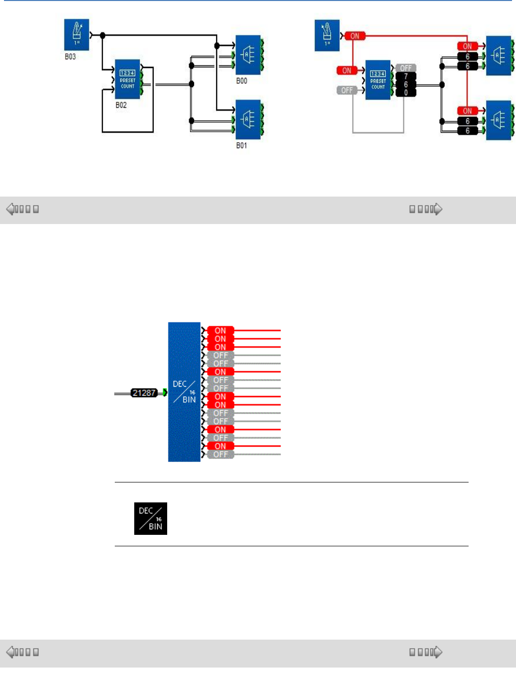
em4 soft Online Help
140
1.4.2.7.11 DEC/BIN Words-to-Bits Conversion
( § 1.4.2.7.10 )
( § 1.4.2.7.12 )
Description
The DEC/BIN function breaks down an integer (16-bit) type input into 16 bit-type
outputs.
Illustration:
Access
The function is accessible from the CALC function bar.
Inputs/Outputs
This function supports 1 integer type 16-bit input:
This function supports 16 discrete outputs: BIT01 (least significant byte) ...
BIT16 (most significant byte).
1.4.2.7.12 BIN/DEC Bits to Words Conversion
( § 1.4.2.7.11 )
( § 1.4.2.7.13 )
Description
The BIN/DEC function produces a 16-bit integer-type output from 16 inputs of
the following type: Bit

em4 soft Online Help
141
Illustration:
Access
The function is accessible from the CALC function bar.
Inputs/Outputs
This function supports 16 discrete inputs: BIT01 (least significant byte) ... BIT16
(most significant byte).
This function supports one 16-bit integer-type output.
1.4.2.7.13 SPLIT BY 4
( §
1.4.2.7.1
2 )
( § 1.4.2.7.14 )
This function is used to split a 16-bit word into four 16-bit words with values between 0 and 15.
Input:
INPUT: 16-bit words to be split.
Outputs:
OUTPUT 1 LOW: 16-bit words varying from 0 to 15.
OUTPUT 2: 16-bit words varying from 0 to 15.
OUTPUT 3: 16-bit words varying from 0 to 15.
OUTPUT 4 HIGH: 16-bit words varying from 0 to 15.
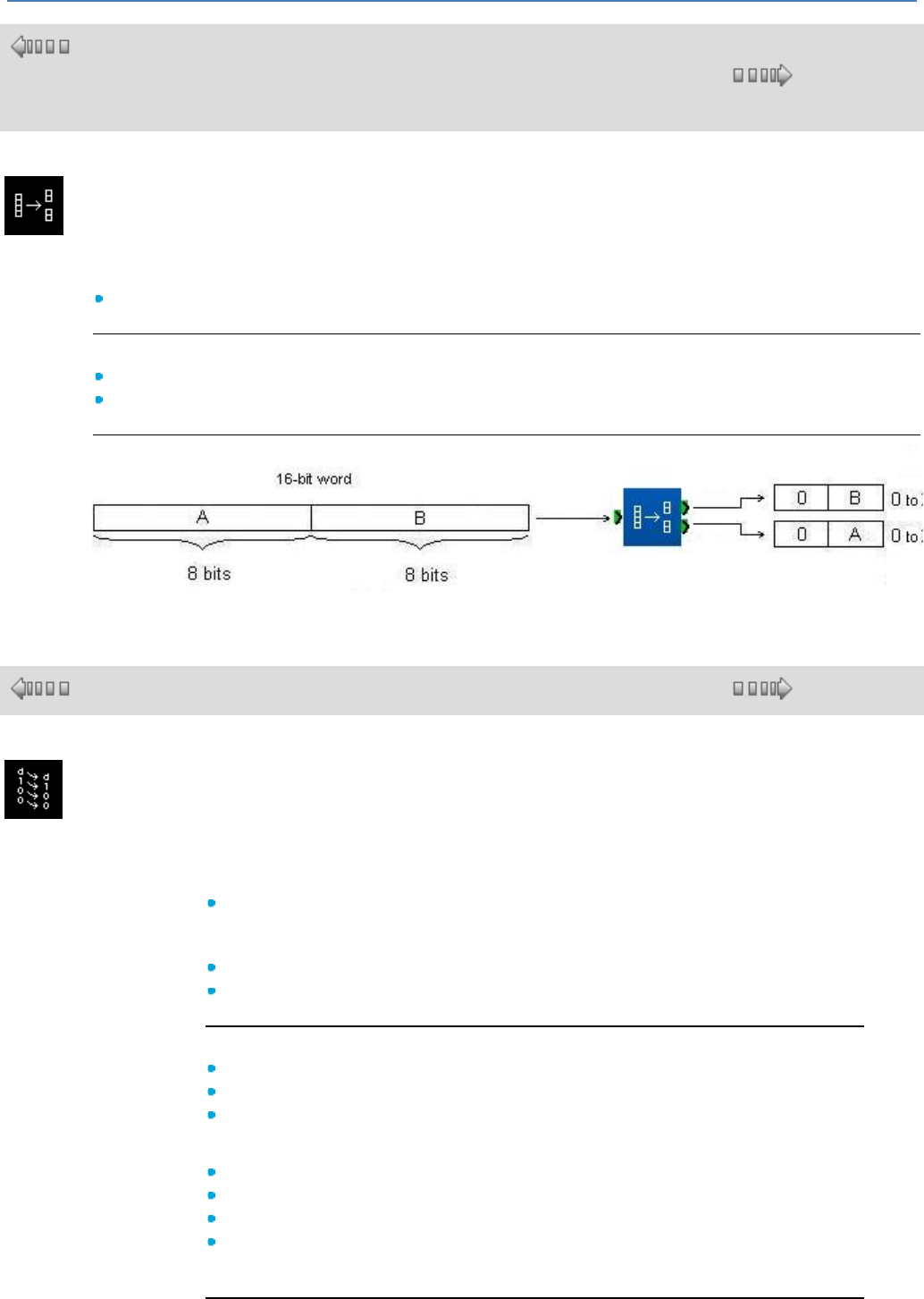
em4 soft Online Help
142
1.4.2.7.14 SPLIT BY 2
( §
1.4.2.7.1
3 )
( § 1.4.2.7.15 )
This function is used to split a 16-bit word into two 16-bit words with values between 0 and 255.
Input:
INPUT: 16-bit words to be split.
Outputs:
OUTPUT 1 LOW: 16-bit words varying from 0 to 255.
OUTPUT 2 HIGH: 16-bit words varying from 0 to 255.
1.4.2.7.15 SHIFT REGISTER bit
( § 1.4.2.7.14 )
( § 1.4.2.7.16 )
This function operates the shifting of bits in a 16-bit word on each rising edge of the
clock.
Inputs:
CLOCK : A rising edge detected on this input causes shifting of the 16-bit word
and loading of the bit currently on the Data input in place of the least significant
bit of the 16-bit word.
DATA : Value of the bit to be loaded on a rising edge of the clock input.
RESET : Used to reset the 16-bit word and all the outputs to zero.
Outputs:
B0: Value of the bit in position 0 of the 16-bit word.
B1: Value of the bit in position 1 of the 16-bit word.
B2: Value of the bit in position 2 of the 16-bit word.
...
B13: Value of the bit in position 13 of the 16-bit word.
B14: Value of the bit in position 14 of the 16-bit word.
B15: Value of the bit in position 15 of the 16-bit word.
NEXT BLOCK BIT: Bit ready to be copied to another shift register block on the
next rising edge of the clock input.
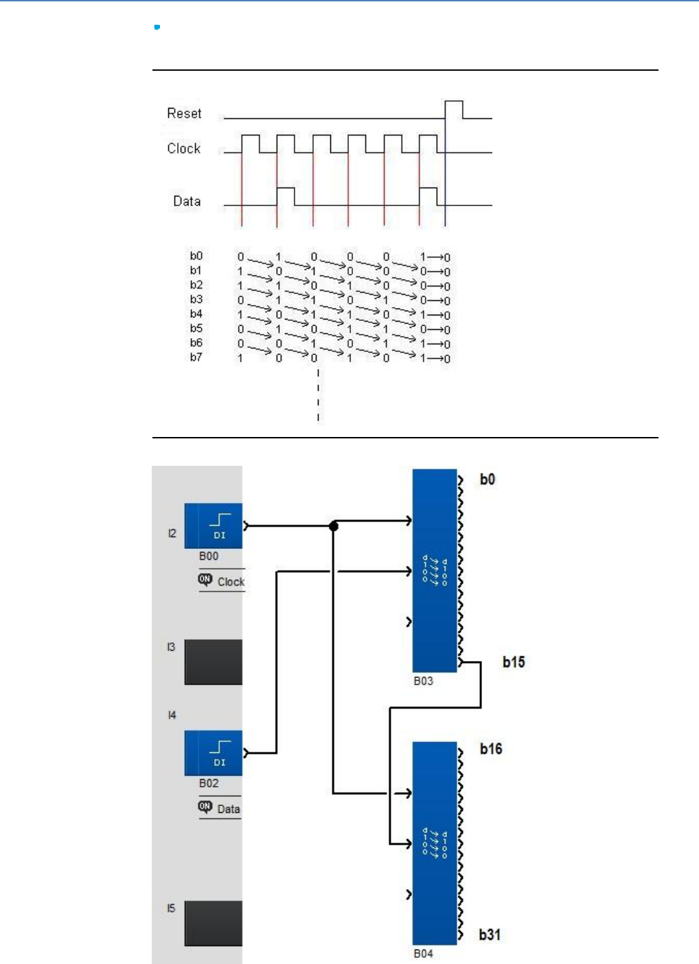
em4 soft Online Help
143
Parameter:
SAVE ON POWER BREAK: Chooses whether or not the function is reinitialised
if the controller power supply is disconnected.
Principle:
Example with two shift registers:
em4 soft Online Help
144
1.4.2.7.16 SHIFT REGISTER word
( § 1.4.2.7.15 )
( § 1.4.2.7.17 )
This function shifts the 16-bit words on each rising edge of the clock.
Inputs:
CLOCK : A rising edge detected on this input shifts the 16-bit words OUT0 to
OUT1, OUT1 to OUT2 ..., OUT7 to NEXT OUT. The last word is lost.
DATA : Value of the word to be loaded on a rising edge of the CLOCK input.
RESET : Used to set the all the outputs to zero.
Outputs:
OUT 0 : Output 0.
OUT 1 : Output 1.
OUT 2 : Output 2.
OUT 3 : Output 3.
OUT 4 : Output 4.
OUT 5 : Output 5.
OUT 6 : Output 6.
OUT 7 : Output 7.
NEXT OUT : Bit ready to be copied to a shift register on the next edge
Parameter:
SAVE ON POWER BREAK : Chooses whether or not the function is
reinitialised if the controller power supply is disconnected.
1.4.2.7.17 TRANSFER FUNCTION y=f(x)
( § 1.4.2.7.16 )
( § 1.4.2.7.18 )
This function is a table of correspondence between the X input and the Y output.
Input:
X : When the input equals a value present in column X of the table, the
corresponding value in column Y is then applied as an output. If the value
present as an input is between two values in the X column then an approximate
value of Y is calculated as follows:
OUTPUT = (INPUT-X1) * (Y2-Y1)/(X2-X1) + Y1.
Output:
Y : Value corresponding to the X input in the table.
Parameter:
The table of correspondence is created from a csv file which is opened by
clicking on "File, Open, *.csv".
The file must comply with the following format :
Using a spreadsheet, create two columns, one for the Xs and one for the Ys.
em4 soft Online Help
145
Each box must contain a single value.
-32768 ≤ X ≤ 32767.
-32768 ≤ Y ≤ 32767.
The file must contain a maximum of 256 rows.
The values of the Xs must be arranged in ascending order.
Save the file in .csv format with the ';' or ',' separator. Do not use ',' or '.'
(32,000 or 32.000). Only use whole numbers.
Example of file
1.4.2.7.18 TIMER TRANSFER FUNCTION
( § 1.4.2.7.17 )
( § 1.4.2.8 )
This function is a correspondence table for the Minutes operating time and the Y
output.
Inputs:
VALIDATION : Enables the function, at 1 if not connected. Once enabled, the
value of the Y output corresponding to t0 is enabled. The output value is
calculated once a minute, in accordance with the table or using the formula: Y =
(MINUTES-X1) * (Y2-Y1)/(X2-X1) + Y1, if the value is not in the table (where
MINUTES1 < MINUTES < MINUTES2, Y1 = f(MINUTES1) and Y2 =
f(MINUTES2)).
RESET : If enabled, return to t0.
Outputs::
Y : Corresponding table value (exact value or approximate value).
CHRONOMETER : Current value in minutes elapsed since the function was
enabled.
END OF CYCLE : Last minutes value reached.
Parameter:
The table of correspondence is created from a csv file which is opened by
clicking on "File, Open, *.csv".
The file must comply with the following format:
Using a spreadsheet, create two columns, one for the Xs and one for the Ys.
Each box must contain a single value.
0 ≤ Minutes ≤ 32767.
-32768 ≤ Y ≤ 32767.
The file must contain a maximum of 256 rows.
The values of the Minutes must be arranged in ascending order.
Save the file in .csv format with the ; separator.
Example of file.
1.4.2.8 LOGIC functions
( § 1.4.2.7.18 )
( § 1.4.2.8.1 )
In FBD language, it is possible to use logic functions and Boolean functions in
the block diagrams.
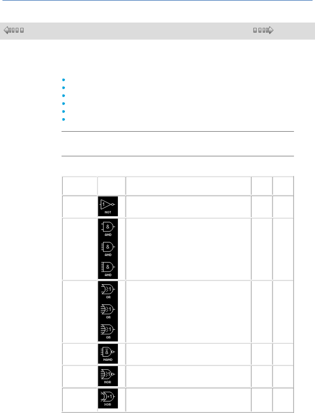
em4 soft Online Help
146
1.4.2.8.1 Logic Functions
( § 1.4.2.8 )
( § 1.4.2.8.2 )
At a Glance
In FBD language, it is possible to use logic functions in the block diagrams. The
available functions are:
The NOT function (NOT),
The AND function (AND),
The OR function (OR),
The NAND function (NAND),
The NOR function (NOR),
The EXCLUSIVE OR function (XOR).
Access
These inputs can be accessed from the LOGIC window.
Logical functions
The following table shows the various logic functions:
Function
Symbol
Description
Number
of
inputs
Input
type
NOT
If the input is inactive or not connected, the output is
active.
If the input is active, the output is inactive.
1
Digital
AND
If all the inputs are active or not connected, the output is
active.
If at least one input is inactive, the output is inactive.
2, 4, 6
Digital
OR
If at least one input is active, the output is active.
If all the inputs are inactive or not connected, the output
is inactive.
2, 4, 6
Digital
NAND
If at least one input is inactive, the output is active.
If all the inputs are active or not connected, the output is
inactive.
4
Digital
NOR
If all the inputs are inactive or not connected, the output
is active.
If at least one input is active, the output is inactive.
4
Digital
EXCLUSIVE
OR
If an input is inactive and the other input is active or not
connected, the output is active.
If both inputs are active or inactive or not connected, the
output is inactive.
2
Digital
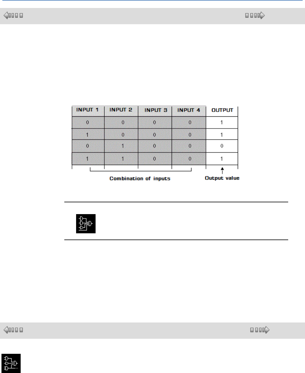
em4 soft Online Help
147
1.4.2.8.2 BOOLEAN EQUATION with 4 inputs/1 output
( § 1.4.2.8.1 )
( § 1.4.2.8.3 )
At a Glance
The BOOLEAN function gives the value of the output according to the combination of
inputs.
The function has four inputs, and therefore 16 combinations. These combinations can
be found in a truth table; for each of these, the output value can be adjusted. The
number of configurable combinations depends on the number of inputs connected to
the function.
Non-connected inputs are set to 0.
The following diagram shows an example of part of the Boolean function truth table:
Access
The function is accessible from the LOGIC function bar.
Parameters
Having connected at least one input, you can configure the value of the output in the
truth table, in the Parameters window.
The output values can be 0 for the Inactive state, and 1 for the Active state.
By selecting the Output ON if result is TRUE option, the output takes the value
configured in the truth table.
By selecting the Output OFF if result is TRUE option, the output takes the inverse
value of the value configured in the truth table.
1.4.2.8.3 BOOLEAN EQUATION with 6 inputs/2 outputs
( § 1.4.2.8.2 )
( § 1.4.2.9 )
This function executes logic operations for all possible Boolean equations with six
inputs and two outputs.
To select a Boolean equation, simply connect the selected INPUTS.
Once the connection has been made, open the Parameters window under the
Parameters tab to display a truth table containing all possible combinations of the
values present on the function input blocks (greyed out) and the output values which
will be issued by the two outputs corresponding to the input combination (white field
which can be edited by the user).
The values displayed correspond to 0 for OFF and 1 for ON. The value can be
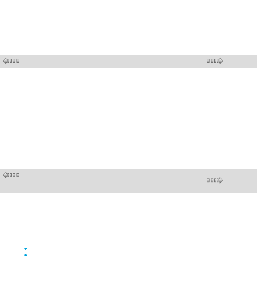
em4 soft Online Help
148
inverted by clicking on it with the mouse.
The result of each output can be inverted. If the user selects the "Output ON if result
is TRUE" option in the Parameters window the function block OUTPUT will be
exactly as indicated in the truth table. If the user selects the "Output OFF if result is
TRUE" option the OUTPUT will be the inverse of what is indicated in the truth table.
As indicated in the truth table, the non-connected input values are all set to 0 (OFF).
1.4.2.9 SFC Functions
( § 1.4.2.8.3 )
( § 1.4.2.9.1 )
At a Glance
Subject of this Section
This section provides information on the different SFC (Sequential Function
Chart) functions using FBD language.
What's in this Section?
This section contains the following topics:
Overview of functions, using steps, transitions, divergences, convergences,
loops, etc.
SFC functions, errors, etc.
1.4.2.9.1 Presentation of SFC Functions
( §
1.4.2.9 )
( § 1.4.2.9.2 )
General
SFC (Sequential Function Chart) functions are similar to Grafcet language, according to standard IEC
1131-3.
Grafcet is used to represent the functioning of a sequential automation operation in a structured and
graphic form.
The principle is simple: a graph containing SFC functions is read from top to bottom, and is principally
composed of:
Steps,
Transitions.
Steps are all placed in succession, and are controlled by transitions. When a step is active, you must wait
for the following transition to become active before carrying on to the following step. Associated with each
step is an action (OUTPUT), which sends orders to other functions (Discrete output / logical / standard
functions).
FBD Representation
The following diagram shows a Grafcet representation with SFC functions in FBD language:
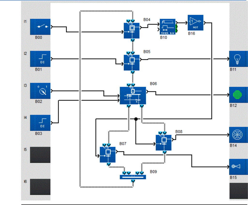
em4 soft Online Help
149
Independent Charts
An independent chart is a set of SFC functions interconnected by input and output function links. Each
of the charts performs an automation function. In a wiring diagram it is possible to create various
independent charts.
The following diagram shows an example of two independent charts in a wiring diagram:
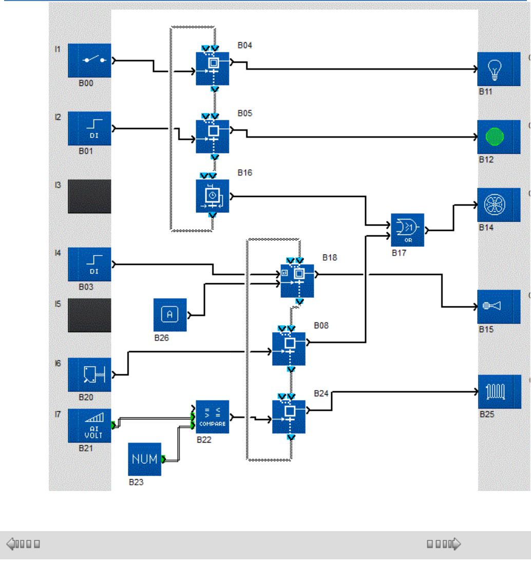
em4 soft Online Help
150
1.4.2.9.2 Using the SFC Steps and Transitions
( § 1.4.2.9.1 )
( § 1.4.2.9.3 )
Description
Steps and transitions can be used to represent and control consecutive operating
phases.
Each operating phase is represented by a symbol called a step. When this operating
phase takes place, the step is said to be active. In this case the step is said by
definition to contain a status token.
The step's active status is seen by the setting to ON of a observation Discrete of the
step.
For the operating phase to terminate, the phase ending must be authorized or
commanded. For this, a transition command Discrete input is set to ON.
The transition is then said to be passing and the status token crosses it. It therefore
disappears from the step and is led to the status token circulation output.
Consequently, the observation Discrete is set to OFF.
When the operating phase is terminated, the step becomes inactive and the
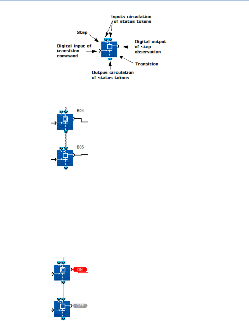
em4 soft Online Help
151
observation Discrete switches to OFF.
Illustration:
The switching off of an operating phase (B01) is immediately followed by the start-up
of the following operating phase (B02). The following operating phase is also
symbolized by a new step, and its end is also controlled by a transition.
Illustration:
To show the fact that the switching off of operating phase B01 is followed (in
sequence) by operating phase B02, the B01 status token circulation output is linked to
one of the circulation inputs of the B02 status tokens.
In this case, when the switch to ON of the B01 transition command makes this
passing, the token present in the B01 step "falls" through the passing transition to the
B02 step, where it stays as long as the Discrete command input of the B02 transition
remains set to OFF (blocked transition).
The Discrete observation output for the B02 step activity switches to ON. As soon as
the B02 transition becomes passing, the token now present in step B02 escapes by
the status token circulation output, the operating phase associated with the step of
block B02 ends and the Discrete observation output of step 2 switches to OFF.
Operation
The mechanism is broken down into four steps.
Phase 1, operation in progress: step 1 active (stable status)
End of operating phase 1: transition 1 active (momentary status)
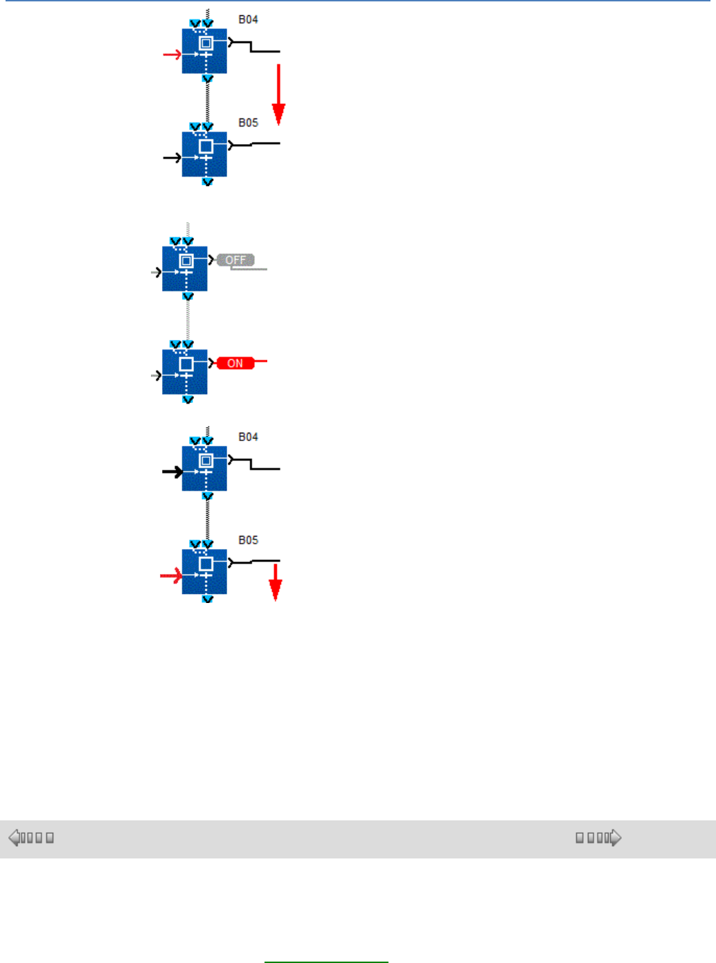
em4 soft Online Help
152
Status
token circulation
Phase 2, operation in progress: step 2 active (stable status)
End of operating phase 2: transition 2 active (momentary status)
Status
token circulation
If step 1 is inactive, the associated operating phase (B01) is not in progress, so the
status token is not present in step 1 by definition. Hence, switching the Discrete input
command of transition 1 to ON, causing the passing transition to have no effect as
there is no token in step1, it cannot "fall".
The Discrete inputs controlling each transition and Discrete outputs that observe each
step can be connected to the other FBD blocks with Discrete inputs and outputs.
For example, a Boolean combination of inputs can command transition 1, a button
can command transition 2, the step 1 observation Boolean can switch a relay and the
step 2 observation Boolean can activate the message display.
1.4.2.9.3 Use of AND Divergences
( § 1.4.2.9.2 )
( § 1.4.2.9.4 )
Description
The AND divergence is used to represent and command simultaneous operating
phases. This representation of a string of operating phases describes the opposite
mechanism to the AND convergence( § 1.4.2.9.5 ).
An operating phase (B01) can be followed by two operating phases that take place at
the same time, and which assign, for example, two command devices to the same
hardware.

em4 soft Online Help
153
To represent this operating mode, a function called AND DIVERGENCE TO 2 SFC
BRANCHES (or DIV AND 2) is used, which is linked to two step functions that each
symbolize one of the simultaneous operating phases.
When the transition command input of block B01 is set to ON, the token, if present in
step B01, migrates from this step, through transition B01, then doubled into two
tokens which, each one falling into steps B03 and B04, show the activation of the two
parallel operating phases.
Mechanism
End of operating phase 1 in progress: step B01 active (stable status)
End of operating phase 1: transition 1 active (momentary status)
Status token circulation
Status token doubling
Operation phases 2 and 3 simultaneously in progress: steps B03 and B04 active
(stable statuses)
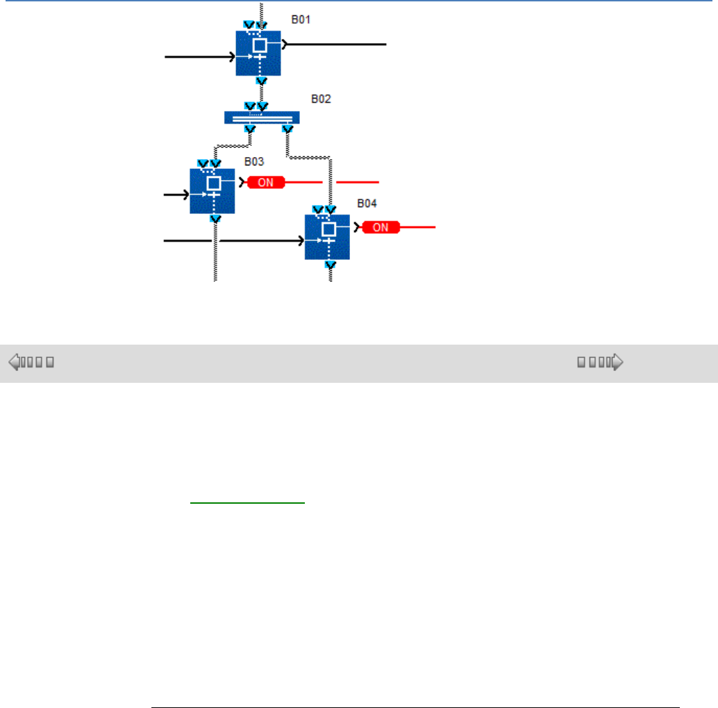
em4 soft Online Help
154
1.4.2.9.4 Use of OR Divergences
( § 1.4.2.9.3 )
( § 1.4.2.9.5 )
Description
The OR divergence is used to sequence after an operating phase one or two
operating phases from a choice of two possible phases.
This representation of a string of operating phases describes the opposite mechanism
to the OR convergence( § 1.4.2.9.6 ) (CONV-OR 2).
A B01 operating phase can be followed by two operating phases which form a non-
exclusive alternative: operating phase B02, B03 or both are activated at the end of
operating phase B01.
To represent this operating mode, a function called OR DIVERGENCE WITH 2 SFC
BRANCHES (or DIV OR 2) is used, which is linked to two step functions that each
symbolize one of the operating phases for the choice available (B02 and/or B03).
If the status token is present in the step (operating phase B01), the choice is made by
forcing to ON one and/or the other of the command inputs of each B01 transition,
which are respectively linked downstream to steps B02 and B03.
This therefore causes the end of operating phase B01, the migration of the token from
step B01, through the passing transition(s) (the command input of which is set to ON)
to the step connected to it.
Examples
Example 1: one of the two transitions available is active.
Phase 1, operation in progress: step B01 active (stable status):
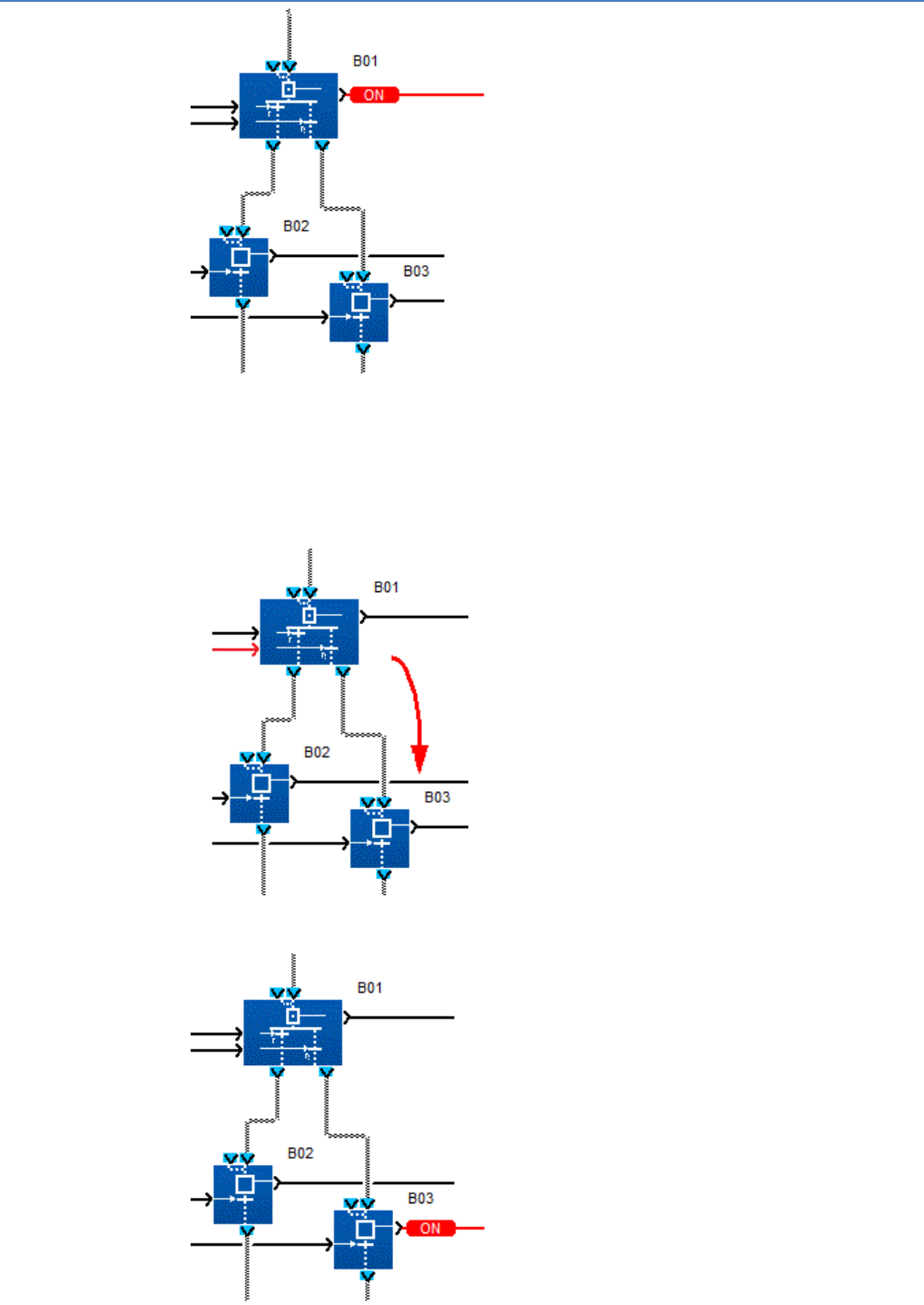
em4 soft Online Help
155
End of operating phase 1: B01 transition 2 active (momentary status):
Status token circulation
Phase 3, operation in progress: step B03 active (stable status):
Example 2: both transitions are passing at once.
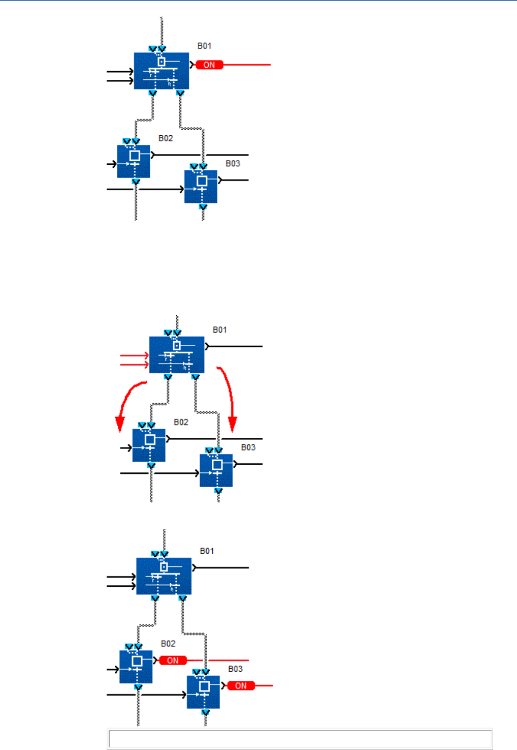
em4 soft Online Help
156
Phase 1, operation in progress: step B01 active (stable status):
End of operating phase 1: B01 transition 1 and 2 active (momentary status):
Status token doubling
Operating phase 2 and 3 in progress: steps B02 and B03 active (stable statuses):
Note: If you want the choice between the two following operating phases to be
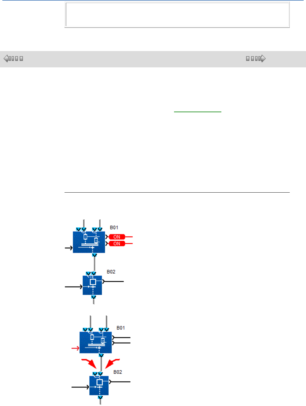
em4 soft Online Help
157
exclusive, one of the two transitions must be commanded by an AND combining the
command of the first transition with the reverse of the command of the second
transition.
1.4.2.9.5 Use of AND convergences
( § 1.4.2.9.4 )
( § 1.4.2.9.6 )
Description
The AND convergence is used to sequence a single operating phase after
simultaneous operating phases. This representation of a string of operating phases
describes the opposite mechanism to the AND divergence( § 1.4.2.9.3 ).
Two simultaneous operating phases (B01 steps 1 and 2) can be followed by a single
operating phase, which can only be triggered after the simultaneous end of both
previous phases.
To represent this operating mode, an SFC function is used called AND
CONVERGENCE WITH 2 SFC BRANCHES (or CONV AND 2), which is linked to the
two upstream step functions, each of which symbolizes one of the simultaneous
operating phases, and to a downstream step which symbolizes the single phase
which links onto the two previous operating phases.
Each of the tokens migrates from its respective step, through its associated transition,
fuses into a single token, which, falling into step B02, shows the activation of the next
single operating phases.
Mechanism
Operating phase 1 and 2 in progress: B01 step 1 and 2 simultaneously active (stable
status):
End of operating phase 1 and 2: transition B01 active (momentary status):
Fusing of 2 status tokens.
Circulation of resulting token.
Phase 3, operation in progress: step B02 active (stable status):
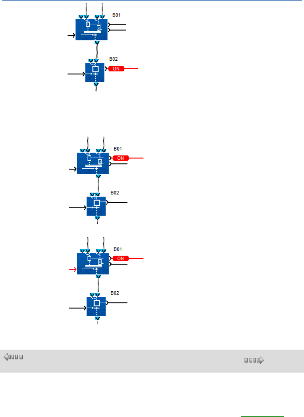
em4 soft Online Help
158
If a single token is present in one of the upstream steps and the other is empty
(inactive), then even if the transition is set to ON, nothing happens. The step
containing the token stays active (Discrete observation output of the step set to ON)
and the downstream step (B03) stays inactive.
Phase 1, operation in progress: only step 1 is active (stable status) but step 2 is
inactive:
Phase 1, operation in progress: transition B01 active (stable status):
1.4.2.9.6 Use of OR convergences
( § 1.4.2.9.5
)
( § 1.4.2.9.7 )
Description
The OR convergence is used to sequence a same operating phase after one or the
other of two previous operating phases (simultaneous or not). This representation of a
string of operating phases describes the opposite mechanism to the OR divergence(
§ 1.4.2.9.4 ) (DIV OR 2).
Two operating phases, simultaneous or not, (steps B01 and/or B02) are followed by a
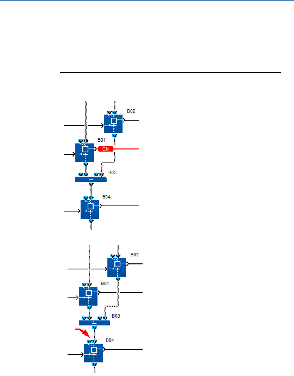
em4 soft Online Help
159
single operating phase which can only be triggered after the end of one of the two
previous phases (once transition B01 or B02 is set to ON).
To represent this operating mode, an SFC function is used called OR
CONVERGENCE WITH 2 SFC BRANCHES (or CONV OR 2), which is linked to the
two upstream transitions, each of which control the end of an operating phase (step
B01, step B02), and to a downstream step (B03) which symbolizes the single phase
which is linked after one or the other of the two previous operating phases.
The first command input that makes a transition passing while the activation token is
present in the associated step, lets the token migrate to the downstream step (B03)
which symbolizes the commitment of operating phase 3.
Example
Example 1: transition 1 is made passing while operating phase 1 is in progress.
Phase 1, operation in progress: B01 step 1 active (stable status):
End of operating phase 1: transition B01 active (momentary status):
Status token circulation
Phase 3, operation in progress: B04 step 1 active (stable status):
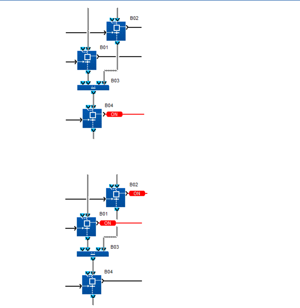
em4 soft Online Help
160
Example 2: transition 1 and transition 2 are made simultaneously passing while
operating phases 1 and 2 are simultaneously in progress.
Operating phases 1 and 2 simultaneously in progress: step B01 and B02
simultaneously active (momentary status):
Simultaneous end of operating phases 1 and 2: transition B01 and B02 simultaneously
active (momentary status):
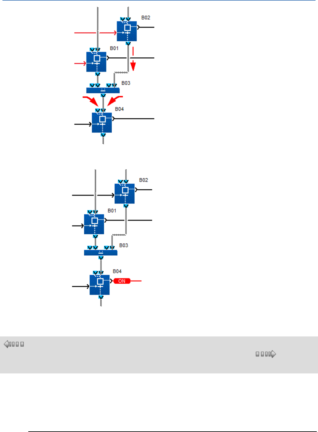
em4 soft Online Help
161
Status token circulation and fusion
Phase 3, operation in progress: step B04 active (stable status):
1.4.2.9.7 Using SFC loops
( §
1.4.2.9.
6 )
( § 1.4.2.9.8 )
Description
Loops are used to build a sequence of operating phases without end.
Most PLCs are designed to operate by continually linking a sequence of operating phases after an
initialization phase. To create this link, the programmer must loop to itself "status token circulation"-type
links.
Example
End of operating phase 1 in progress: step B01 active (stable status)
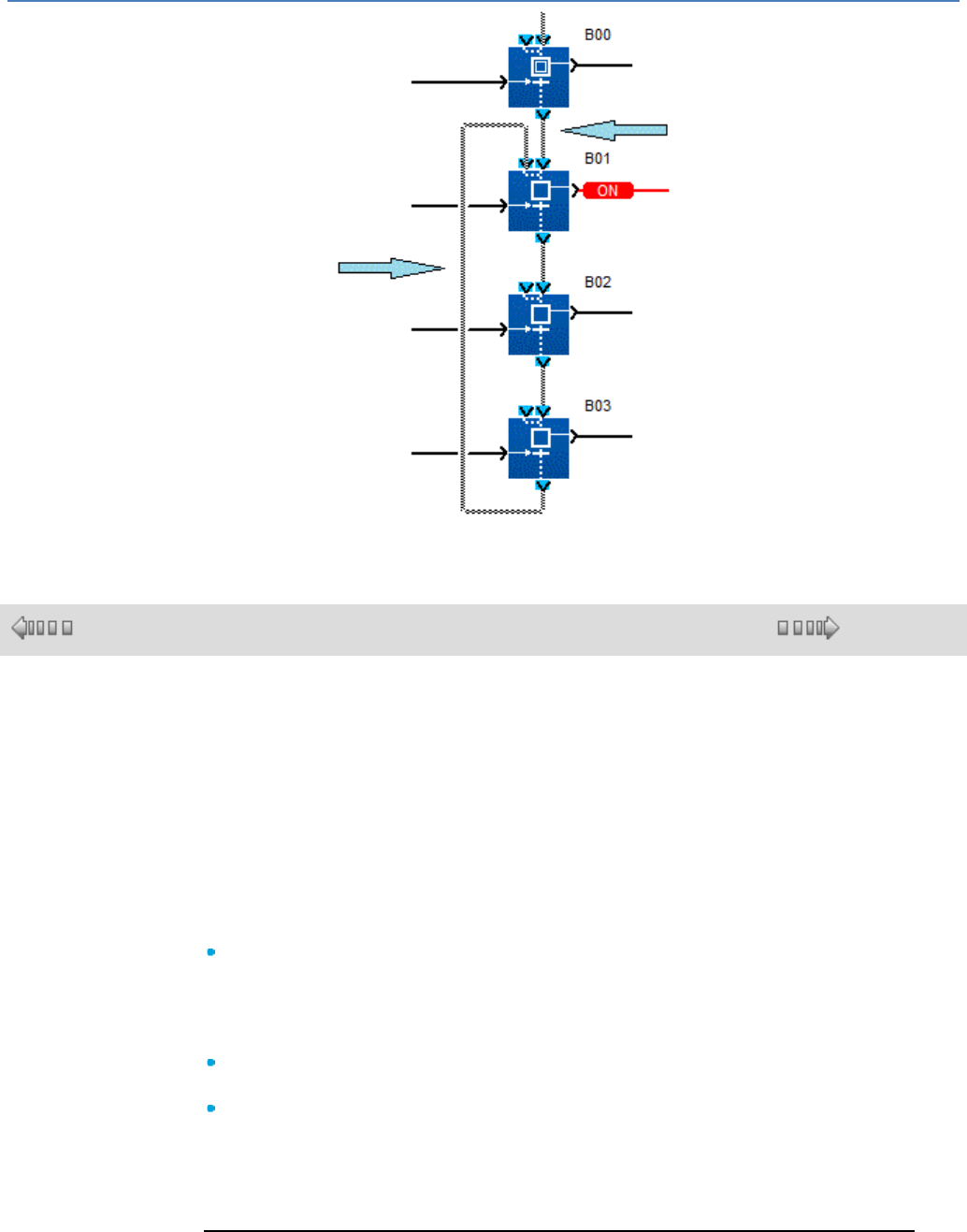
em4 soft Online Help
162
Relooping of a status token
circulation-type link
This joining of 2 performed inside the
inside the function behaves as an OR
convergence (CONV OR 2)
1.4.2.9.8 Initialization of an SFC at the Start of the Program
( § 1.4.2.9.7 )
( § 1.4.2.9.9 )
Description
On launching (initializing) the program containing an SFC, you must know which
operating phase needs to be activated first, and therefore which step contains a
status token at the time of initialization.
To show this step in the chart, it is essential to use at least one SFC function called
INITIAL SFC STEP (INIT STEP) or RESETTABLE INITIAL SFC STEP (RESET-INIT)
per independent SFC.
An independent SFC is a set of SFC functions connected together by links between
the token inputs/outputs (circulation of status tokens).
On launching the user program (once the INITIALIZE AND SWITCH ON order is
executed):
All charts that contain one or more INITIAL SFC STEP (INIT STEP) functions are
automatically initialized. This or these INIT STEP functions contain a status token
which symbolizes the same number of active operating phases.
All other steps belonging to the other functions contain no token, and all the
operating phases they symbolize are inactive.
This automatic initialization also takes place on restart after a power outage. The
positions the status tokens had at the time of the power outage are lost,
In all the charts containing a RESET-INIT function, it is now MANDATORY, RIGHT
AT THE START OF THE PROGRAM, to place an ON signal on the
REINITIALIZATION input, and to disable the module OUTPUTS which may be
subject to interference. On restart after a power outage, the positions the status
tokens had at the time of the power outage are restored.
Example
Example 1: SFC with two INIT STEP functions.
Initialization and switch on of the program, initial operating phases 1 and 2
simultaneously in progress, step B01 and B02 simultaneously active (stable statuses)
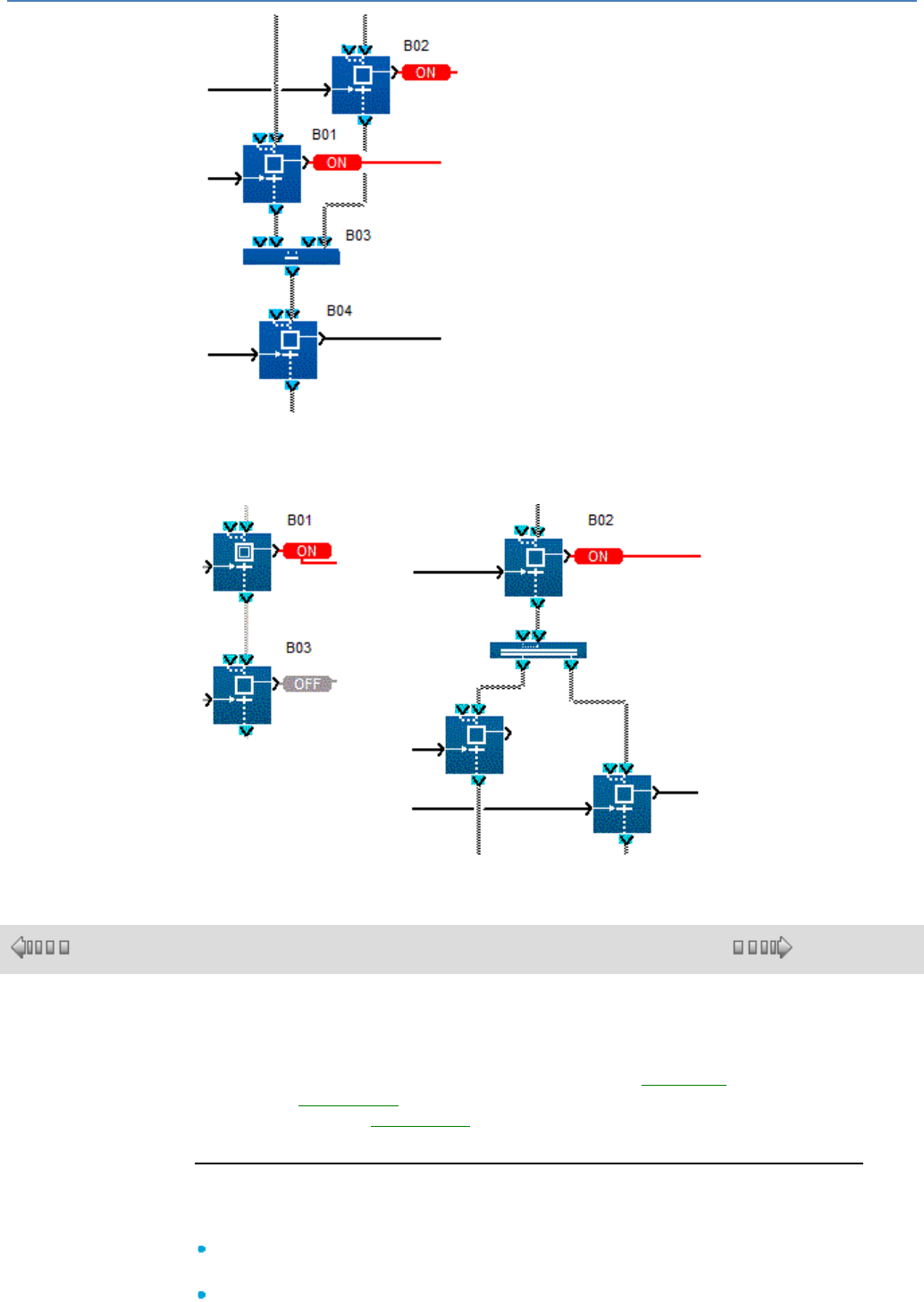
em4 soft Online Help
163
Example 2: two independent SFC each have an INITIAL SFC STEP function.
Initialization and switch on of the program, initial operating phases 1 and 2
simultaneously in progress, step B01 and B02 simultaneously active in two
independent SFCs (stable statuses)
1.4.2.9.9 Initialization of SFC Charts
( § 1.4.2.9.8 )
( § 1.4.2.9.10 )
At a Glance
A program containing one or more SFC charts must be initialized when launched.
To perform this initialization you must insert at least one INIT STEP( § 1.4.2.9.13 )
function or a RESET-INIT( § 1.4.2.9.12 ) function in each of the independent charts.
If a chart contains the RESET-INIT( § 1.4.2.9.12 ) function, it can also be initialized
when the program is running.
Initialization at Startup or on Power Return
On program startup, when the Initialize and switch on command is executed, or
when power is restored, the following occurs:
All the STEP OUTPUTS of the INIT SFC or RESET-INIT functions are
activated and all the other chart functions are deactivated,
The former step states are lost.
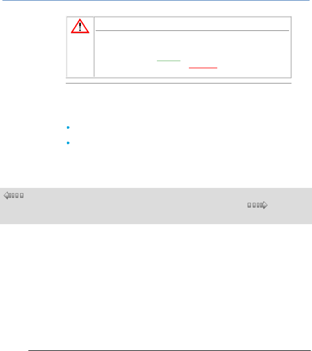
em4 soft Online Help
164
If a chart contains a RESET-INIT function, the steps are restored to the states they
were in at the time of the power outage.
CAUTION
RESET input
At the start of an SFC chart it is mandatory to connect to the
REINITIALIZATION input of the RESET INIT function the COLD
START output for the STATUS( § 1.4.2.6.11 ) function.
Failure to follow this instruction can result in injury or equipment
damage.
Initialization in Progress
When a program containing one or more independent SFC charts is running, a chart
containing the RESET-INIT function can be reset independently of the other SFC
charts. This initialization is performed by activating the REINITIALIZATION of the
RESET-INIT function which achieves the following:
All the STEP OUTPUTS of the INIT SFC and RESET-INIT functions are
activated and all the other chart functions are deactivated,
The functions of the other independent charts are not affected.
As long as the REINITIALIZATION is active, the steps are forced as described
above regardless of the transition values of the chart functions.
1.4.2.9.10 Re-initialization of an SFC in the Course of the Program
( §
1.4.2.9.
9 )
( § 1.4.2.9.11 )
Description
Over the course of the program containing one or more independent SFCs, a chart containing the
RESET-INIT function can be reinitialized independently from the other SFCs. This initialization is triggered
by setting to ON the Discrete input called REINITIALIZATION of the RESET-INIT function.
This input can be connected to the other FBD blocks using Discrete outputs. For example, a Boolean
combination of inputs can command this initialization input.
During execution of the user program, once the REINITIALIZATION input of the RESET-INIT function
switches to ON, each INIT STEP function and the RESET-INIT function belonging to the same SFC each
contain a status token that symbolizes the same number of active operating phases.
All other steps belonging to the other functions of the same SFC contain no token: all the operating
phases they symbolize are inactive.
All other functions belonging to other SFCs independent from the previous one are not assigned.
As long as the REINITIALIZATION input is set to ON, the steps are forced as described above without
taking into account the values applied to the command inputs associated with all transitions of the chart
functions.
Example
The left-hand SFC chart has an initial step which can be reinitialized and the right-hand one an initial step.
In this example, the non-initial steps are active.
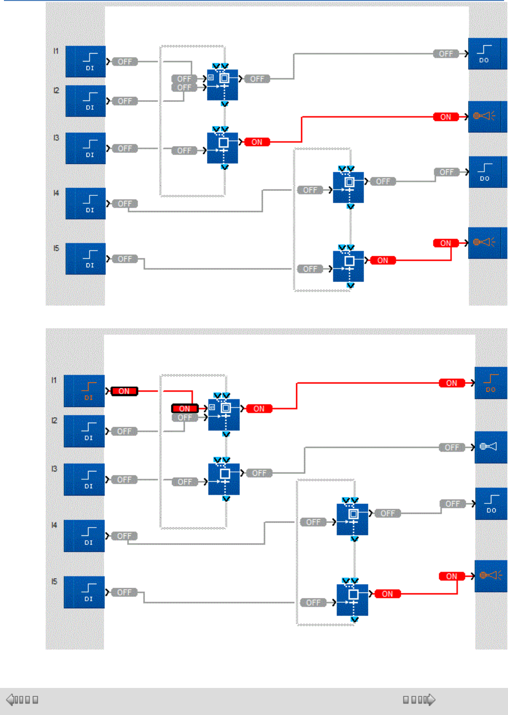
em4 soft Online Help
165
Initialization while the program is running: activation of the Reset input activates the initial step of the left-
hand chart but has no effect on execution of the right-hand chart.
1.4.2.9.11 SFC Functions
( § 1.4.2.9.10 )
( § 1.4.2.9.12 )
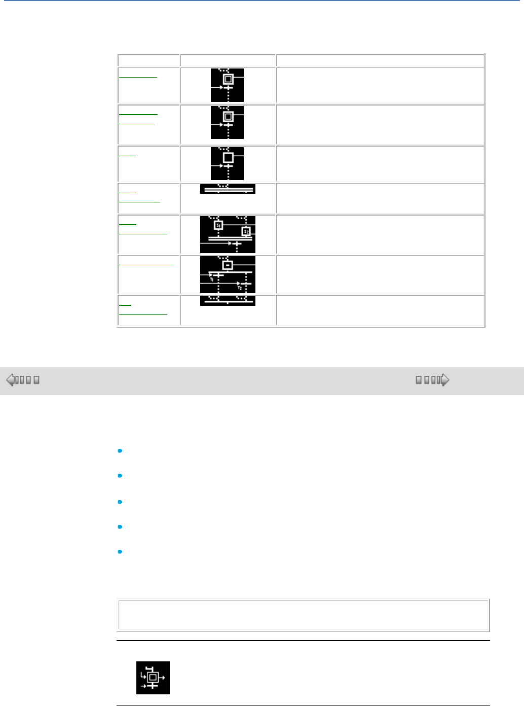
em4 soft Online Help
166
At a Glance
The following table shows the different functions that make up an SFC program:
Name
Symbol
Description
Initial Step( §
1.4.2.9.13 )
Initial step of an SFC chart.
Resettable
initial step( §
1.4.2.9.12 )
Initial step of an SFC chart with initialization of the step
by command.
Initializes the entire connecting chart containing the reset
init.
Step( §
1.4.2.9.14 )
Step which transmits an order to another FBD function.
AND
Divergence( §
1.4.2.9.17 )
Transition of one or two steps toward two steps.
AND
Convergence( §
1.4.2.9.18 )
Transition of two simultaneous steps toward one step.
OR Divergence(
§ 1.4.2.9.15 )
Transition of a step toward one or two steps.
OR
Convergence( §
1.4.2.9.16 )
Transition of one to four steps toward a single step.
1.4.2.9.12 Resettable Step
( § 1.4.2.9.11 )
( § 1.4.2.9.13 )
Description
The RESET INIT function can be used, when the RESET function is activated:
to activate the STEP OUTPUT for the function, which is the initial step of the
SFC chart,
and to reinitialize all of the other active steps in the chart to which it belongs.
If the RESET input is not active, it operates in the following manner:
If INPUT 1 or INPUT 2 is active, then the STEP OUTPUT is activated and
remains active even after the inputs have disappeared,
If the TRANSITION input is active, then the STEP OUTPUT is deactivated and
the STEP TRANSITION OUTPUT is activated,
If none of the inputs is active and only the STEP OUTPUT is inactive, then the
output remains inactive.
During a power failure, this function enables current values of the chart to be saved
and retrieved when power is restored.
Note: An SFC chart can have only one RESET function. Each of the program's
independent charts can contain only one RESET INIT function.
Access
The function is accessible from the SFC function bar.
Inputs/Outputs
The function uses:
em4 soft Online Help
167
Two inputs, INPUT 1 and INPUT 2 to activate the step output,
A RESET input for the program and its steps,
A TRANSITION input to deactivate the step located downstream from this one.
Note: If not connected, inputs other than RESET are in inactive state.
The function provides:
A STEP OUTPUT,
A STEP TRANSITION OUTPUT.
Warning
CAUTION
RESET input
At the start of an SFC chart it is mandatory to connect to the
REINITIALIZATION input of the RESET INIT function the COLD
START output for the STATUS( § 1.4.2.6.11 ) function and to disable
the outputs of the controller which are dependent on the outputs of the
SFC chart steps.
Failure to follow these instructions can result in injury or
equipment damage.
1.4.2.9.13 SFC Initial Step
( § 1.4.2.9.12 )
( § 1.4.2.9.14 )
Description
The INIT STEP function is an initial step of an SFC chart. It operates normally as
follows:
If INPUT 1 or INPUT 2 is active, then the STEP OUTPUT is activated and
remains active even after the inputs have disappeared,
If the TRANSITION input is active, then the STEP OUTPUT is deactivated and
the STEP TRANSITION OUTPUT is activated,
If none of the inputs is active and only the STEP OUTPUT is inactive, then the
output remains inactive.
Note: An SFC chart must have at least one INIT STEP function. Each of the
program's independent charts can contain several INIT STEP functions.
If there is no RESET INIT function in the SFC chart, then the INIT STEP function
is automatically initialized in the following cases:
Beginning of a simulation session,
when switching to ON mode,
when normal operation is resumed following a power failure.
Access
The function is accessible from the SFC function bar.
Inputs/Outputs
The function uses:
Two inputs INPUT 1 and INPUT 2 to activate the step output,
A TRANSITION input to activate the step located downstream from this one.
Note: If not connected, inputs are in inactive state.
The function provides:
A STEP OUTPUT,
em4 soft Online Help
168
A STEP TRANSITION OUTPUT.
1.4.2.9.14 SFC Step
( § 1.4.2.9.13 )
( § 1.4.2.9.15 )
Description
The STEP function is a step of an SFC chart. The step symbolizes an operational
phase of a control device or PLC.
An action is connected to each STEP OUTPUT to transmit commands to other
functions (Discrete, logical, standard output). It operates in the following manner:
If INPUT 1 or INPUT 2 is active, then the STEP OUTPUT is activated and
remains active even after the inputs have disappeared,
If the TRANSITION input is active, then the STEP OUTPUT is deactivated and
the STEP TRANSITION OUTPUT is activated,
If none of the inputs is active and only the STEP OUTPUT is inactive, then the
output remains inactive.
Access
The function is accessible from the SFC function bar.
Inputs/Outputs
The function uses:
Two inputs INPUT 1 and INPUT 2 to activate the step output,
A TRANSITION input to activate the step located downstream from this one.
Note: If not connected, inputs are in inactive state.
The function provides:
A STEP OUTPUT,
A STEP TRANSITION OUTPUT.
1.4.2.9.15 Divergence to OR
( § 1.4.2.9.14 )
( § 1.4.2.9.16 )
Description
The DIV OR 2 function enables a transition of one step to be simultaneously
made toward one or two steps.
If the STEP INPUT 1 or STEP INPUT 2 is active, then the STEP OUTPUT is
activated,
If the TRANSITION INPUT 1 and the STEP OUTPUT is active:
The STEP OUTPUT is deactivated,
TRANSITION OUTPUT 1 WITH DIVERGENCE TO OR is activated.
If the TRANSITION INPUT 2 and the STEP OUTPUT is active:
The STEP OUTPUT is deactivated,
TRANSITION OUTPUT 2 WITH DIVERGENCE TO OR is activated.
If the TRANSITION 1 and TRANSITION 2 inputs are active and the STEP
OUTPUT is active:
The STEP OUTPUT is deactivated,
The TRANSITION OUTPUT 1 WITH DIVERGENCE TO ORand the
TRANSITION OUTPUT 2 WITH DIVERGENCE TO OR are activated.
em4 soft Online Help
169
Access
The function is accessible from the SFC function bar.
Inputs/Outputs
The function uses:
Two inputs, INPUT 1 and INPUT 2 to activate the step output,
Two inputs, TRANSITION 1 and TRANSITION 2 to activate the transition step
output(s).
Note: If not connected, inputs are in the inactive state.
The function provides:
A STEP OUTPUT,
A TRANSITION OUTPUT 1 WITH DIVERGENCE TO OR,
A TRANSITION OUTPUT 2 WITH DIVERGENCE TO OR.
1.4.2.9.16 Convergence to OR
( § 1.4.2.9.15 )
( § 1.4.2.9.17 )
Description
The CONV OR 2 function enables a transition of one to four step(s) to be
simultaneously made toward one step.
If INPUT 1 or INPUT 2 or INPUT 3 or INPUT 4 OF CONVERGENCE TO OR is
active, then the OUTPUT OF CONVERGENCE TO OR is activated,
If none of these inputs is active, then the OUTPUT OF CONVERGENCE TO
OR is inactive.
Access
The function is accessible from the SFC function bar.
Inputs/Outputs
The function uses four input s that allow activation of the transition output.
INPUT 1 OF CONVERGENCE TO OR,
INPUT 2 OF CONVERGENCE TO OR,
INPUT 3 OF CONVERGENCE TO OR,
INPUT 4 OF CONVERGENCE TO OR.
Note: If not connected, inputs are in the inactive state.
The function provides an OUTPUT OF CONVERGENCE TO OR.
1.4.2.9.17 Divergence to AND
( § 1.4.2.9.16 )
( § 1.4.2.9.18 )
Description
The DIV AND 2 function enables a transition of one or two steps to be
simultaneously made toward two steps.
If INPUT 1 or INPUT 2 of DIVERGENCE TO AND is active, then OUTPUT 1
em4 soft Online Help
170
and OUTPUT 2 OF DIVERGENCE TO AND are activated,
If none of these inputs is active, then OUTPUT 1 and OUTPUT 2 OF
DIVERGENCE TO AND are inactive.
Access
The function is accessible from the SFC function bar.
Inputs/Outputs
The function uses two inputs that allow activation of the transition outputs:
INPUT 1 OF DIVERGENCE TO AND,
INPUT 2 OF DIVERGENCE TO AND.
Note: If not connected, inputs are in inactive state.
The function provides two outputs:
OUTPUT 1 OF DIVERGENCE TO AND,
OUTPUT 2 OF DIVERGENCE TO AND,
1.4.2.9.18 Convergence to AND
( § 1.4.2.9.17 )
( § 1.4.2.9.19 )
Description
The CONV AND 2 function enables a transition of two steps to be simultaneously
made toward one step.
If INPUT 1 or INPUT 2 is active, then STEP OUTPUT 1 OF CONVERGENCE
TO AND is activated and remains active even after the inputs have
disappeared,
If INPUT 3 or INPUT 4 is active, then STEP OUTPUT 2 OF CONVERGENCE
TO AND is activated and remains active even after the inputs have
disappeared,
If STEP OUTPUT 1 OF CONVERGENCE TO AND and STEP OUTPUT 2 OF
CONVERGENCE TO AND are active and the TRANSITION input is also active,
then:
STEP OUTPUT 1 and STEP OUTPUT 2 OF CONVERGENCE TO AND are
deactivated,
The TRANSITION OUTPUT is activated.
If none of these inputs is active, then STEP OUTPUT 1 and STEP OUTPUT 2
OF CONVERGENCE TO AND are inactive,
If the TRANSITION input is active but STEP OUTPUT 1 or STEP OUTPUT 2
OF CONVERGENCE TO AND is inactive, STEP OUTPUT 1 or STEP OUTPUT
2 OF CONVERGENCE TO AND does not change state and the TRANSITION
OUTPUT remains inactive.
Access
The function is accessible from the SFC function bar.
Inputs/Outputs
The function uses:
Two inputs INPUT 1 and INPUT 2 to activate step output 1,
Two inputs INPUT 3 and INPUT 4 to activate step output 2,
A TRANSITION input to activate the step located downstream from this one.
em4 soft Online Help
171
Note: If not connected, inputs are in inactive state.
The function provides:
A STEP OUTPUT 1 OF CONVERGENCE TO AND,
A STEP OUTPUT 2 OF CONVERGENCE TO AND,
A TRANSITION OUTPUT.
1.4.2.9.19 Wait SFC Step
( § 1.4.2.9.18 )
( § 1.4.2.9.20 )
This function is used to set up a wait phase or step for a PLC or a device.
If a status token is present at STEP INPUT 1 or STEP INPUT 2, it is stored
immediately in the function step, switching the STEP OUTPUT to ON.
This token remains stored in the step until the time defined by the WAIT TIME
parameter has elapsed. At this point, the status token crosses the transition and
disappears from the step. The STEP OUTPUT is set to OFF and the token is then
available on the STEP TRANSITION OUTPUT and can be stored in the step or
steps connected downstream of this output.
If there is no status token present at either input (STEP INPUT 1 and STEP INPUT
2) and if the step does not already contain a status token, the step remains empty
and the STEP OUTPUT indicates OFF.
The non-connected STEP INPUT 1 or STEP INPUT 2 inputs are at neutral values
for the function, ie. no token present in the step input.
1.4.2.9.20 Move SFC Step
( §
1.4.2.9.1
9 )
( § 1.4.2.9.21 )
This function is used to set up a move step for a motor controlled by the PLC to a position specified on
the TARGET input.
The motor is controlled by the following three outputs:
ON (0 or 1) : The motor runs when the ON signal is at 1. Otherwise, it stops (with optional braking
depending on the motor configuration)
DIRECTION (0 ou 1) : Indicates the direction of motor rotation (1 clockwise, 0 anticlockwise)
SPEED (0 à 30000): : Indicates the motor speed in rpm
Note 1 : When several move steps are linked, it is possible to combine their motor control signals
using the MOTOR MULTIPLEXER function.
The move consists of 5 steps:
Acceleration to HIGH SPEED (ACCELERATION and HIGH SPEED parameters)
Constant speed plateau until the motor reaches the approach zone (APPROACH parameter)
Deceleration to LOW SPEED (DECELERATION and LOW SPEED parameters)
Low-speed approach until the motor reaches the target position (TARGET input)
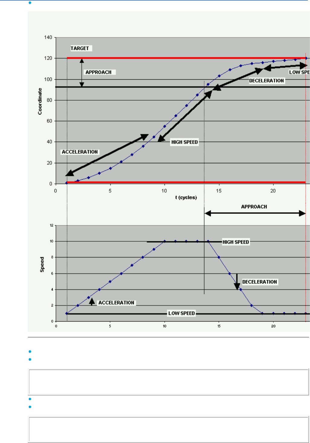
em4 soft Online Help
172
Stop on target. Transition to the next SFC step
Move parameters:
HIGH SPEED (maximum) (0 à 30000) : Indicates high speed in rpm (see note 2)
LOW SPEED (minimum) (0 à 30000) : Indicates low speed in rpm (see note 2)
Note 2 : In order to bring the speed output within the PWM range [0..100], a GAIN block must be
inserted just before the analog output controlling the motor speed. This block should be set to 100/N
where N is the maximum motor speed.
ACCELERATION (0 à 2767) : Indicates the speed increment on each PLC cycle (see note 3)
DECELERATION (0 à 2767) : Indicates the speed decrement on each PLC cycle (see note 3)
Note 3 : The standard PLC cycle is 10 ms. Setting acceleration to 10 will make the motor accelerate
by 10 rpm every 10 ms, hence from 0 to 1000 rpm in 1 second. If the cycle is 20 ms, then the motor
will accelerate from 0 to 1000 rpm in 2 seconds
em4 soft Online Help
173
APPROACH (0 à 32767) : Indicates the distance before the target during which the motor decelerates
and then approaches at low speed before stopping (notes 4 and 5)
TARGET (-32768 à 32767) : Indicates the value to be reached on the POSITION input in order for the
move to be deemed complete (see note 4).
Note 4 : (EXAMPLE) Motors in the CROUZET 80040xxx and 80080xxx brushless range generate 12
pulses per revolution. A position of 1200 therefore corresponds to 1200/12=100 motor rotations. If the
motor is fitted with a gearbox with ratio 10, the geared motor output shaft will therefore make
100/10=10 rotations. And if the output shaft drives a belt on a 40 mm diameter pulley, this belt will
advance by 10 x 3.14 x 40 = 1256 mm = 1.256 m
Note 5 : For optimum stopping, adjust the APPROACH parameter so as to obtain a short plateau at
low speed before stopping. If the plateau does not exist, increase the APPROACH parameter. If the
plateau is unnecessarily long, reduce the APPROACH parameter. If the motor slows down too
abruptly, reduce the DECELERATION parameter
If a status token is present at STEP INPUT 1 or STEP INPUT 2, it is stored immediately in the function
step, switching the ON output controlling the motor to 1.
This token remains stored in the step until the move is complete. In this case, the status token crosses
the transition and disappears from the step. The ON output is set to 0 and the token is then available on
the STEP TRANSITION OUTPUT and can be stored in the step or steps connected downstream of this
output.
Depending on the DIRECTION OF MOVEMENT option, the move is performed as follows:
ASCENDING DIRECTION : The DIRECTION output is at 1, the move only occurs if the TARGET
value is greater than the POSITION value, until the TARGET position is reached. When POSITION is
greater than TARGET, the move is immediately deemed to be complete.
DESCENDING DIRECTION : The DIRECTION output is at 0, the move only occurs if the TARGET
value is less than the POSITION value, until the TARGET position is reached. When POSITION is less
than TARGET, the move is immediately deemed to be complete.
AUTOMATIC DIRECTION: : The DIRECTION output is at 1 or at 0, depending on whether TARGET is
greater or less than POSITION. The move is deemed to be complete when the POSITION has
returned to the TARGET value.
Note 6 : This function is based on the convention that DIRECTION = 1 makes the motor rotate in order
to make the POSITION value increase, and vice versa. This is the case with CROUZET brushless
motors. In cases where the motor or its rotation sensor do not respect this convention, a NOT relay
should be placed just before the logic output controlling the motor direction.
CAUTION
If this convention is not respected, the motor will rotate indefinitely, which could
move the system it is driving beyond its limits.
There is is no guarantee that the function will work correctly when the speed output is
forced to values in excess of 30000, whether by manual forcing or when using a display.
Failure to follow this instruction can result in serious injury or equipement damage.
1.4.2.9.21 Motor Multiplexer
( § 1.4.2.9.20 )
( § 1.4.2.9.22 )
This function is designed to combine the motor control signals produced by two
linked MOVE SFC steps.
A motor is controlled by the following three signals:
em4 soft Online Help
174
ON (0 ou 1) : The motor runs when the ON signal is at 1. Otherwise, it stops
(with optional braking depending on the motor configuration)
DIRECTION (0 ou 1) : Indicates the direction of motor rotation (1 clockwise, 0
anticlockwise)
SPEED (0 à 32767) : Indicates the motor speed in revolutions per minute.
Note : When more than two MOVE SFC steps are linked, it is possible to
combine them by cascading several MOTOR MULTIPLEXER blocks: The three
motor control signals at the multiplexer output combining the first two steps are
in turn combined with the three signals produced by the third step, etc.
Note : In order to bring the speed output within the PWM range [0..100], a GAIN
block must be inserted before the analog output controlling the motor speed.
This block should be set to 100/N where N is the maximum motor speed.
This function combines the ON1, DIRECTION1 and SPEED1 inputs of the first
motor with the ON2, DIRECTION2 and SPEED2 inputs of the second motor.
At the output:
ON is at 1 if at least one input (ON1 or ON 2) is at 1
If ON1 is at 1 and ON2 at 0, DIRECTION and SPEED correspond to the
DIRECTION1 and ON1 inputs
If ON2 is at 1 and ON1 at 0, DIRECTION and SPEED correspond to the
DIRECTION2 and ON2 inputs
If ON1 and ON2 have the same value, then DIRECTION = 0 and SPEED = 0
Note : In principle, for the same motor, there can only be one active
MOVEMENT SFC step at any given time (ie. ON=1). If several steps combined
by a cascade of MOTOR MULTIPLEXER blocks are active simultaneously, then
the outputs of the last block will have the values ON=1, DIRECTION=0 and
SPEED=0, which will prevent the motor from moving.
1.4.2.9.22 Errors and Warnings Detected in an SFC Chart
( § 1.4.2.9.21 )
( § 1.4.3 )
At a Glance
When editing a chart, you can cause structural errors. The workshop detects them
and generates errors and warnings when:
Switching from Edit mode to Simulation mode,
changing from Edit mode to Debugging mode,
Using the following commands:
Controller Write to the controller,
Controller Compare the controller data with the program,
Edit Check the program.
In all cases, the workshop displays a dialog box in the "Compilation results"
window with a list of Errors and/or Warnings, and puts a red frame around the
function(s) where errors have been found.
The SFC errors are displayed in bold red on the wiring sheet.
Errors
The following table describes the errors according to their numbers:
Type of error
Description
Error 60
An SFC does not have an initial INIT STEP function, and no resettable initial
RESET INIT function. No step will be active when the program is initialized.
Error 61
An independent SFC has several resettable initial RESET INIT functions.
Warnings
em4 soft Online Help
175
The following table describes the warnings according to their numbers:
Type of warning
Description
Warning 70
This warning is generated if several warnings of different types are detected.
Warning 71
This warning is generated if an SFC function output is linked directly to several
SFC function inputs. The AND Divergence function DIV AND can be used to
clear this error.
Warning 72
This warning is generated if:
An output from an SFC function is not connected to another function,
None of the inputs from an SFC function except RESET INIT and INIT STEP
are connected to a function.
1.4.3 FBD Programming
( § 1.4.2.9.22 )
( § 1.4.3.1 )
Overview
Aim of This Chapter
This chapter describes the different functions that can be accessed from the
programming workshop in FBD mode.
What's in this Chapter?
This chapter contains the following sections:
Creating an FBD Application in the Programming Workshop( § 1.4.3.1 )
Manipulating FBD Objects( § 1.4.3.2 )
Debugging an FBD Application in the Programming Workshop( § 1.4.3.3 )
1.4.3.1 Creating an FBD Application in the Programming Workshop
( § 1.4.3 )
( § 1.4.3.1.1 )
At a Glance
Subject of this Section
This section describes the different functions linked to programming in the
programming workshop in FBD mode.
What's in this Section?
This section contains the following topics:
Configuring FBD Program Editing( § 1.4.3.1.1 )
Inserting Function Blocks( § 1.4.3.1.2 )
Creating Links between Function Blocks and/or MACRO( § 1.4.3.1.3 )
Function Block Parameters( § 1.4.3.1.4 )
Display Options( § 1.4.3.1.5 )
Draw( § 1.4.3.1.6 )
Find( § 1.4.3.1.7 )
Display Dependencies( § 1.4.3.1.8 )
Use of Application-Specific Functions( § 1.4.3.1.9 )
1.4.3.1.1 Configuring FBD Program Editing
(
§ 1.4.3.1 )
( § 1.4.3.1.2 )
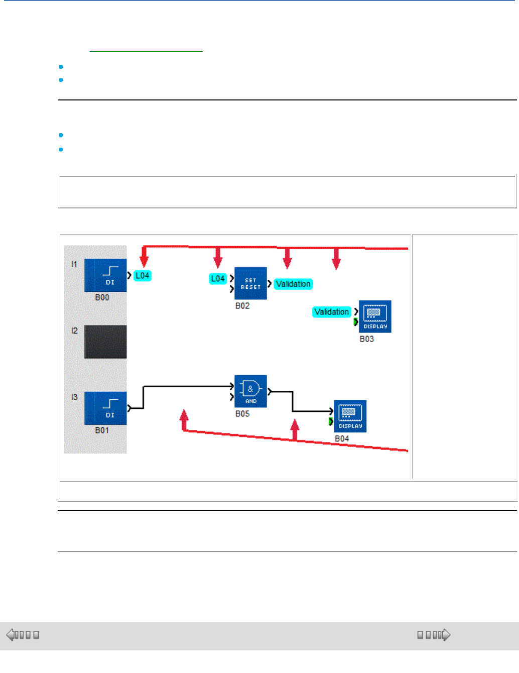
em4 soft Online Help
176
At a Glance
Before creating an FBD program( § 1.1.2 ), you must first set up several options to facilitate editing,
such as:
Defining the wiring mode,
Displaying the editing grid.
Wiring Mode
The links between the function blocks can be of the following type:
Wire by clicking Tools / Wiring mode / Wire,
Text by clicking Tools / Wiring mode / Text, The text is inserted by default, and can be modified
later.
Note: The text displayed at the beginning and end of the link is Lxx type by default (e.g. L04) but
can be modified.
Once the type of link is selected, all new links created will be of the selected type.
The following diagram shows an example of a program with wire- and text-type links:
Text-type links
Wire-type links
Note: Wire mode linking is the default setting on opening the workshop.
Modifying the type of wiring on a link
Double-clicking on the link takes you to a window where you can modify the type of link or the link text.
Displaying the Grid
To help you align blocks in the wiring sheet, you can display a grid by clicking Display / Grid.
1.4.3.1.2 Inserting Function Blocks
( § 1.4.3.1.1 )
( § 1.4.3.1.3 )
At a Glance
To create an FBD program, you must insert various function blocks (FB) in the
wiring sheet, then link these together.
The Edit mode is the default mode on opening the application. This is generally
accessible by clicking menu:Mode / Edit during programming, to switch from one
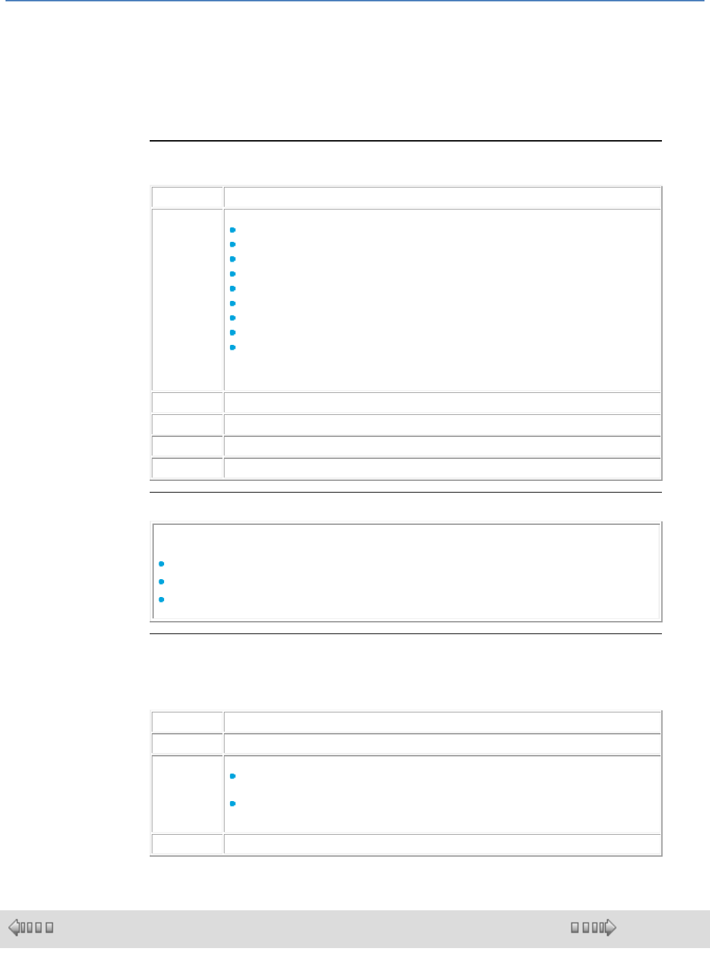
em4 soft Online Help
177
mode to another.
All types of blocks can be placed on the sheet, (including the IN inputs and the OUT
outputs).
The only restrictions apply to IN blocks and OUT blocks that can be positioned on
their dedicated squares only in the event of compatibility between the equipment's
input or output type (controller or extension) and the function block chosen.
If there is an incompatibility, it will not be possible to place the block. If the plot
already has a block, a barred circle appears.
Inserting Function Blocks
The following procedure describes how to insert a function block in a wiring sheet:
Step
Action
1
Select the type of function or Macros to insert.
IN/OUT
CTRL
HMI/COM
APP
PROG
CALC
LOGIC
SFC
MACRO
Important note: these examples of function types are non-contracual and are subject
to futur developments.
2
Left-click on the icon corresponding to the function or the Macro to insert.
3
Drag/drop the selected icon to the wiring sheet.
4
Position the function or the Macro in the required location on the wiring sheet.
5
Repeat steps 2 to 5 to insert all the functions required for the program.
Input Blocks
Note: The following input blocks can only be inserted in the input plots on the left
of the wiring sheet to create a link to the hardware:
Discrete input (DI),
Voltage analog input (AI VOLT),
Current analog input (AI mA),
Plot Position
The positions or relative positions of the input and output plots can be changed in
order to make the wiring diagram as clear as possible. To do this, proceed as
follows:
Step
Action
1
Extend the wiring surface if necessary.
2
Designate the plot to move:
Click on the left part of the plot for inputs or on the right part for outputs, if it contains
the drawing of an IN or OUT type block, and keep the mouse button pressed down,
left click anywhere on the plot if it is empty, and keep the mouse button pressed
down,
3
Move the plot to the required space, release the mouse button.
1.4.3.1.3 Creating Links between Function Blocks and/or MACRO
( § 1.4.3.1.2 )
( § 1.4.3.1.4 )
Overview
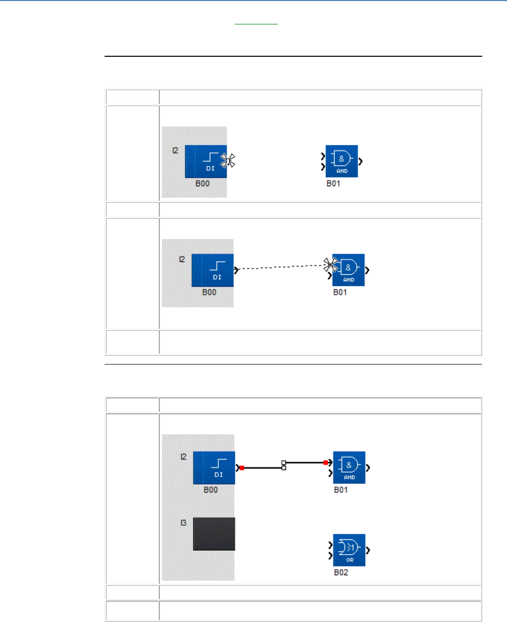
em4 soft Online Help
178
After positioning the function blocks in the wiring sheet, you have to link them
together. If you have created MACROS( § 1.4.3.2.5 ), they should be connected
similarly. You can link an output of a block (function block or MACRO) to an input of
another block or to loop an output back to an input on the same block.
How to Connect one Block to Another
The following procedure shows how to connect one block to another:
Step
Action
1
Left-click on an output of a block.
Result: The mouse cursor is displayed as a star.
2
Keep the left button held down.
3
Continuing to hold down the button, move the cursor over a block input.
Result: The cursor is displayed as a star.
If when moved over the input of a block, the cursor is shown as a circle with a line
through it, this means that the link destination is not correct (incompatible types).
4
Release the mouse button.
Result: A line or numbers are shown between the two linked blocks.
How to Change the Start Point of a Link
The following procedure shows how to change the start point of a link
Step
Action
1
Select the link by clicking on it with the mouse.
Illustration
2
Press the Shift key.
3
Holding down the Shift key, use the mouse to select the end of the link to be modified.
Result: The cursor is displayed as a star.
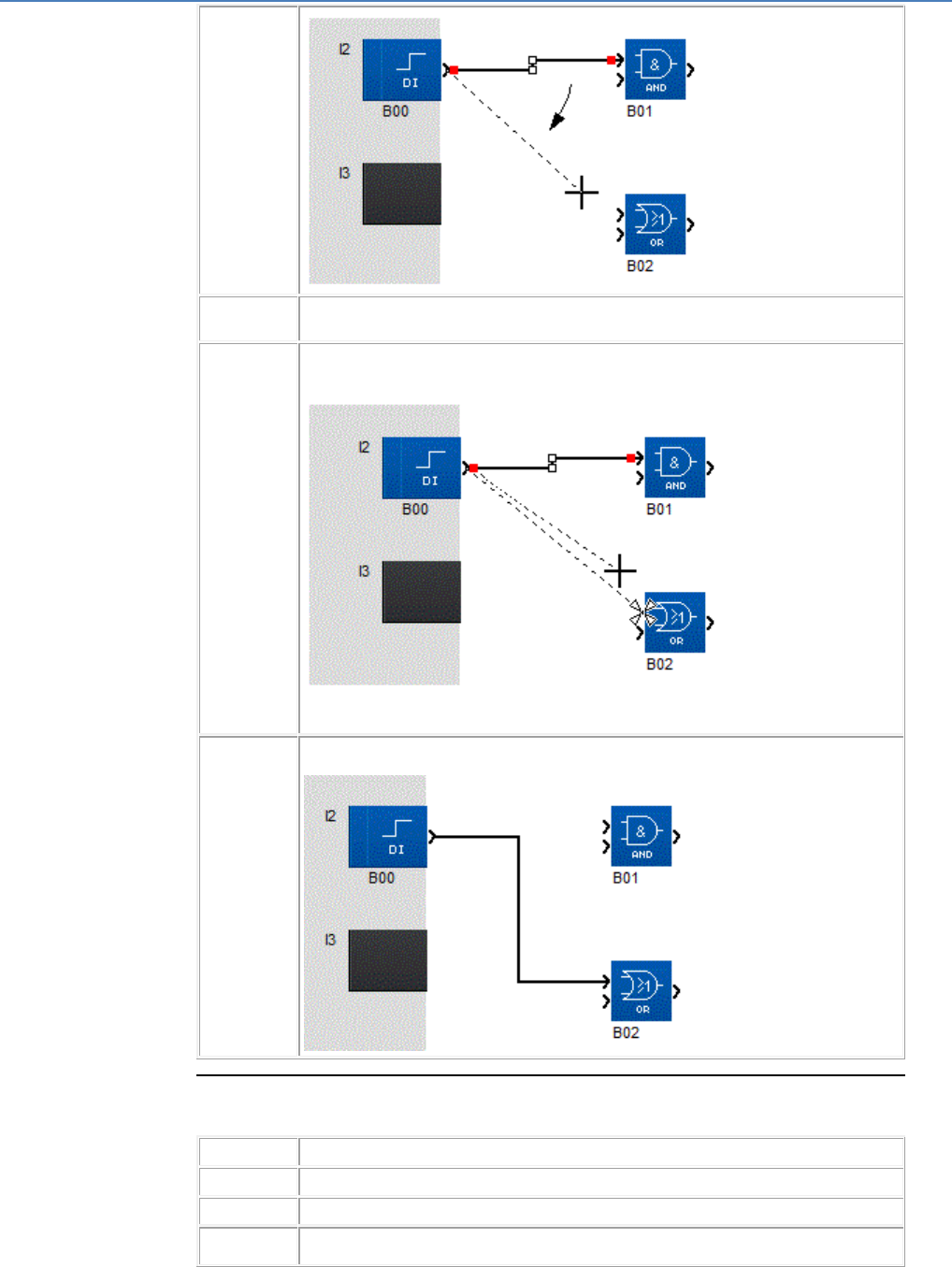
em4 soft Online Help
179
4
Keep the left button held down.
Note: At this stage the Shift key can be released.
5
Continuing to hold down the button, drag the cursor over the input or output of another
block.
Result: The cursor is displayed as a star.
If when moved over the input of a block, the cursor is shown as a circle with a line
through it, this means that the link destination is not correct (incompatible types).
6
Release the mouse button.
Result: A line or numbers are shown between the two linked blocks.
How to Connect one Block to Several Others
The following procedure shows how to connect one block to several others:
Step
Action
1
Press the Ctrl key.
2
Holding down the Ctrl key, left-click on an output of a block.
3
Holding down the Ctrl key and the left mouse button, move the cursor over a block input.
Result: The cursor is displayed as a star.
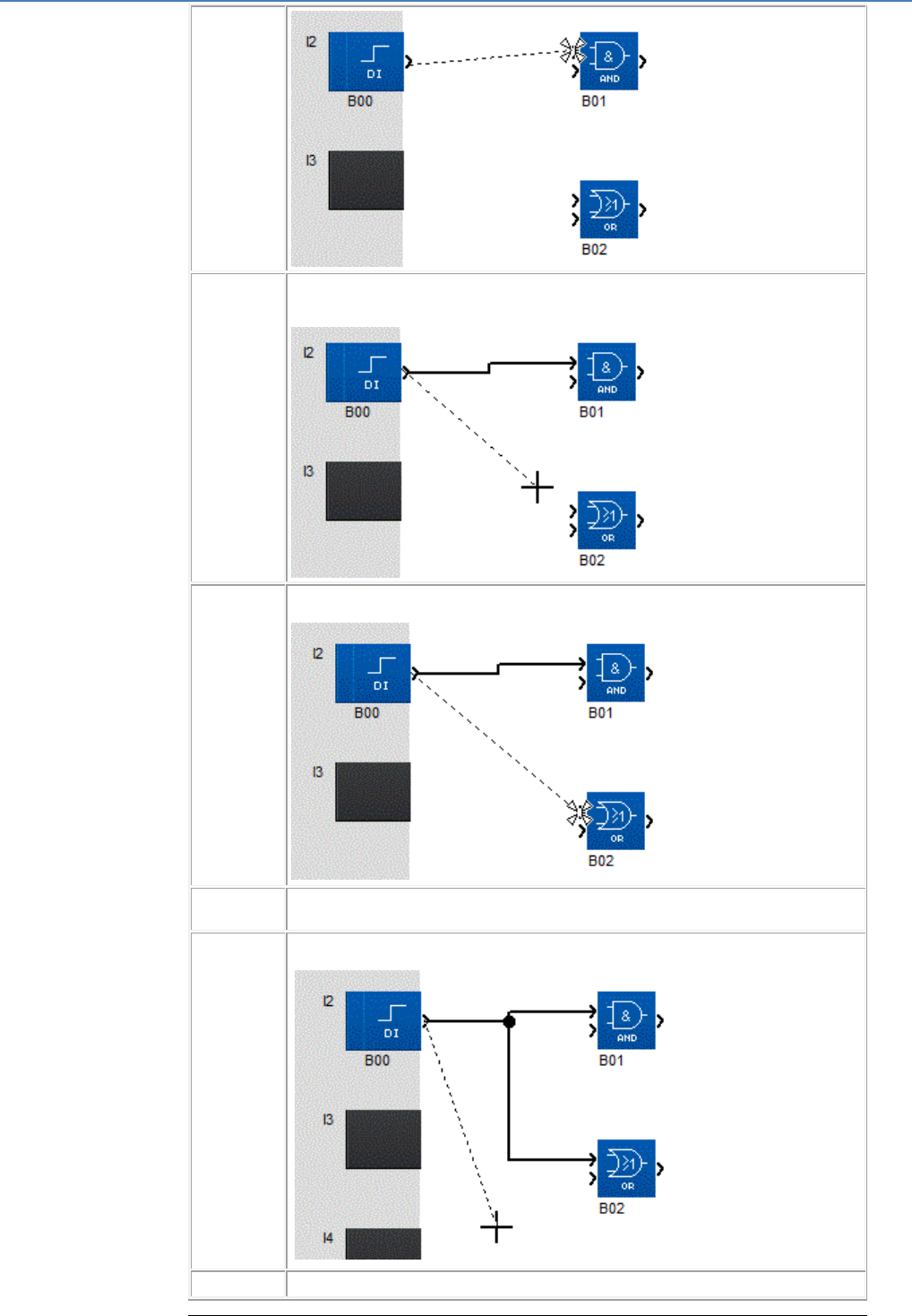
em4 soft Online Help
180
4
Holding down the Ctrl key, release the mouse button.
Result: A line or numbers are shown between the two linked blocks and another dotted
line appears.
5
Continuing to hold down the Ctrl key, move the cursor over another block input.
Result: The cursor is displayed as a star.
6
Continuing to hold down the Ctrl key, click on another block input.
Result: Another link is created.
7
Repeat steps 5 and 6 to create as many links as necessary
.
8
Release the Ctrl key and click anywhere on the wiring sheet.
em4 soft Online Help
181
Types of Link
Depending on the type of data traveling along the link, there are different types of
link.
By default the links are represented as follows:
Discrete data: Continuous black line
Signed integers between -32768 and +32767: Black double line
Link between SFC function blocks: Black interwoven lines
How to Modify the Type of Wiring or Text of a Link
The following procedure shows how to change the appearance of a link.
Step
Action
1
Double-click on the link whose type is to be changed.
2
Select the Wiring mode box to change the link from text type to wiring type or
Select the Text box to change the link from wiring type to text type, and enter the new
text.
1.4.3.1.4 Function Block Parameters
( § 1.4.3.1.3 )
( § 1.4.3.1.5 )
At a Glance
Each of the function blocks has a parameters window. This window consists of one,
two or three tabs:
Comments for all function blocks,
Parameters depending on the function block type (FBD PRESET COUNT),
Summary depending on the function block type (FBD TIME PROG).
Simply double click on the function block to access this window.
Comments Tab
Comments
In the Comment zone you can enter a comment of up to three lines of a maximum
of 16 characters.
On Inputs( § 1.4.2.1.1 )/Discrete Outputs( § 1.4.2.2.1 ) and Analog Inputs( §
1.4.2.1.2 ) function blocks, from the comment tab you can also choose the type of
function block symbol that will be displayed in the wiring sheet.
When a comment has been associated with a function block, an ON/OFF symbol is
displayed underneath and to the left of the block.
The comment is displayed in 2 different ways:
By selecting the corresponding box in the Comments tab,
By clicking on the symbol underneath the FB.
Block number
The following option is also available: Display the block number on the comment
tab. This option is activated by default.
In Simulation or Debugging mode, on launching either of these modes, the block
number is hidden. This can be displayed for each block by opening the parameter
setting window.
Symbols used for block
For certain types of block, you can choose specific symbols to be used when shown
in the wiring sheet (FBD DI, OUT).
When this function is available, the list of available icons is shown in a menu at the
bottom of the window.
To change the icon, simply double click on the desired symbol.
Parameters
Most function blocks have a parameters tab. In this tab, you have to set the
function block's specific parameters. These parameters are described in detail in
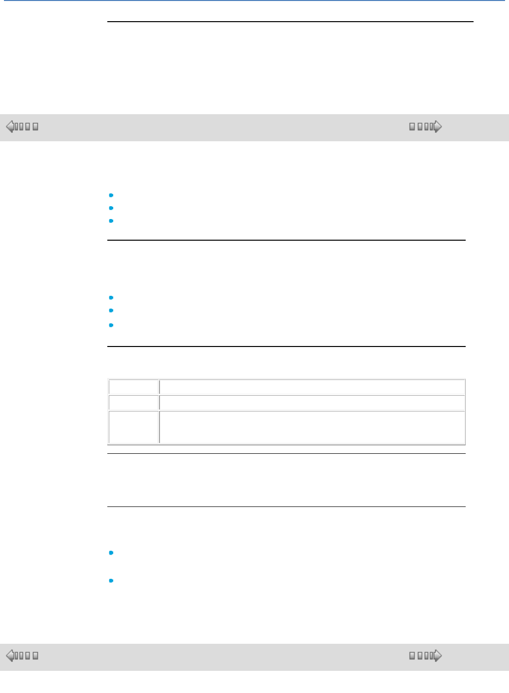
em4 soft Online Help
182
the help for each of the blocks.
Summary
Some function blocks also have a Summary tab (FBD TIME PROG). This window
lists all the actions configured for the block. It provides you with an overview of the
configuration.
1.4.3.1.5 Display Options
( § 1.4.3.1.4 )
( § 1.4.3.1.6 )
At a Glance
For an FBD program, several different display options are available with:
Comments,
Zoom,
Block numbers.
Comments
All of the function blocks can have an associated comment. These comments are
displayed above the block in the wiring sheet.
You can choose to display:
The comment for a block,
All comments with the command Display Comment All,
No program comment Display Comment None.
Displaying a Comment
The following table shows the procedure for displaying a function block comment:
Step
Action
1
Double-click on the block, Comments tab, select the "Display Comment" box.
2
Click on the OFF symbol, if a comment is associated with the block, the symbol is
visible.
Result: The comment for the block is displayed.
Zoom Function
The command Display Zoom allows you to use the zoom to display a part of
the program in detail.
Block Numbers
As with the comments, you can choose to display the program function block
numbers.
All of the function block numbers with the command Display Block
numbers All,
None of the program function block numbers Display Block numbers
None.
1.4.3.1.6 Draw
( § 1.4.3.1.5 )
( § 1.4.3.1.7 )
Overview
In the edit and supervision sheet, you can create square, ellipse or line forms or text.
em4 soft Online Help
183
You can also insert an image in Bmp format.
The line width (3 widths), line color and background color can also be changed.
Creating a Drawing
The table below shows the procedure for inserting a drawing in the wiring or
supervision sheet:
Step
Action
1
Select the Draw menu or the Display, Drawing Bar menu
2
Select the type of drawing to be created:
Line
Rectangle
Ellipse
Text
3
Draw the desired form in the wiring or supervision sheet.
4
If you selected Text, if necessary, double-click on the object created and enter the text.
Inserting an Image
The table below shows the procedure for inserting an image in the wiring or
supervision sheet:
Step
Action
1
Select the Draw menu or the Display, Drawing Bar menu
2
Select Image .
Result: The Open window appears.
3
Select the image file in bmp format.
4
Confirm with Open.
5
Left-click on the wiring or supervision sheet.
Result: A dotted zone the size of the image appears.
6
Place the zone corresponding to the image on the wiring or supervision sheet.
7
Release the left mouse button.
Result: The image appears.
Border
You can create a drawing that is a rectangle or ellipse with or without a border. By
default, the border option is selected. If you would like to remove it or confirm your
choice, use the Draw / Border command. The border color can be modified in the
same way as that of a line.
Line Width
The table below shows the procedure for changing a line width or border of a
drawing:
Step
Action
1
Select the drawing to modify.
2
Select the Width sub-menu from the Draw menu .
3
Choose the width type.
single line
double line
triple line
em4 soft Online Help
184
Result: The drawing width is modified.
Background Color
The table below shows the procedure for changing the background color of a
drawing:
Step
Action
1
Select the drawing to modify.
2
Select the Background Color icon in the Drawing bar
Result: The Color window appears.
3
Choose the new background color.
4
Confirm with OK.
Line and Border Color
The table below shows the procedure for changing the color of borders and lines in
a drawing:
Step
Action
1
Select the drawing to modify.
2
Select the Line Color icon in the Drawing bar
Result: The Color window appears.
3
Choose the new line color.
4
Confirm with OK.
1.4.3.1.7 Find
( § 1.4.3.1.6 )
( § 1.4.3.1.8 )
Overview
The Find command is used to find the following in the edit and supervision
windows:
A function block, from its comment or block number,
A link, from its name
Procedure
The following table shows the procedure for using the Find function:
Step
Action
1
Select the Find command from the Edit menu.
Result: the Find window appears.
2
Enter the string of characters to be found in the Find zone.
3
Check the Whole word only box so that the search is carried out only on the string
to be found.
4
Check the Match case box so that the search takes the case into account (upper
and lower case letters).
5
Launch the search by pressing Next.
Result:
If the search is successful, the function block is highlighted in the window.
If the search is not successful, the No block found window appears.
6
Relaunch the search by pressing Next until the No more blocks window is
displayed.
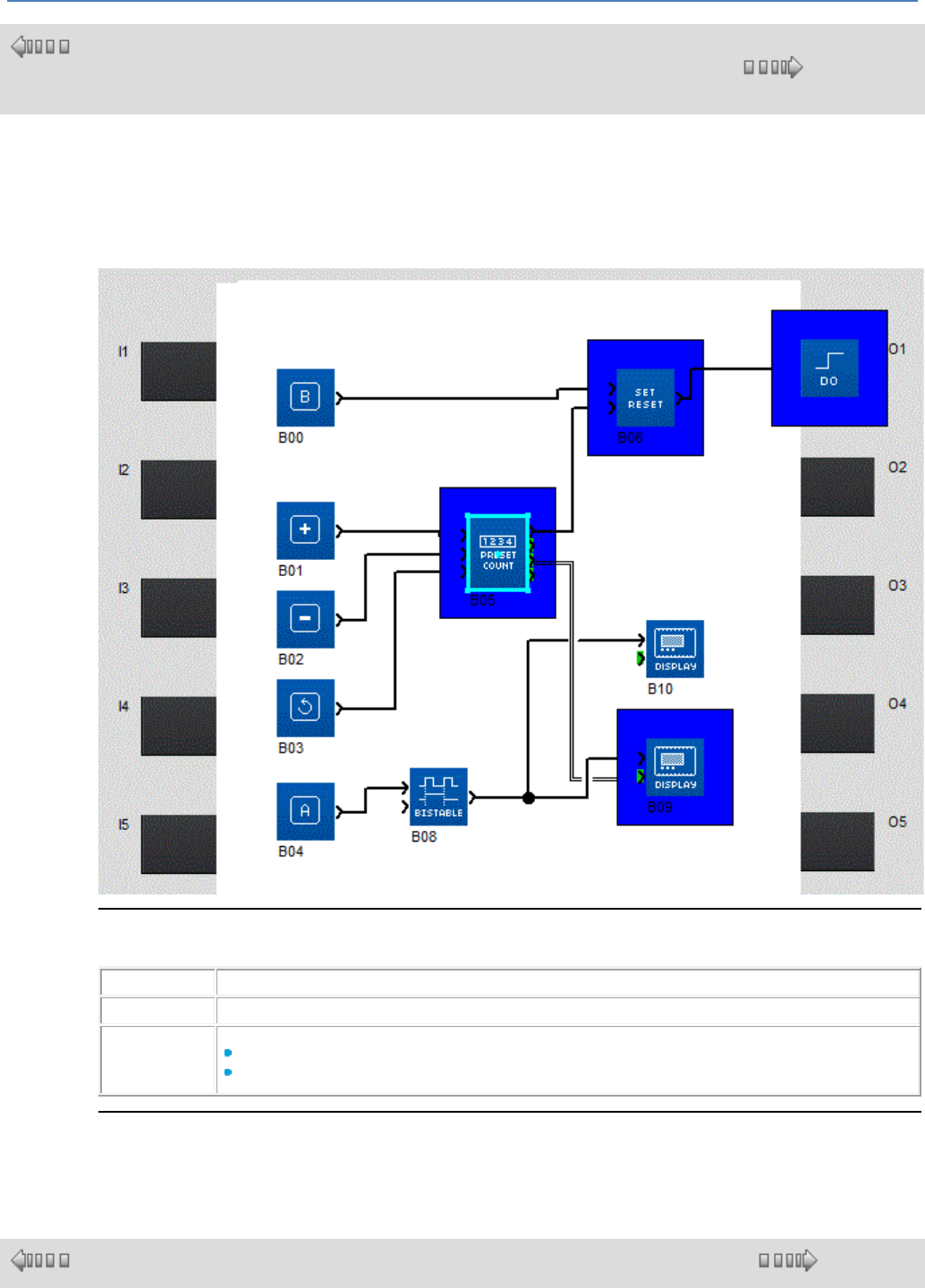
em4 soft Online Help
185
1.4.3.1.8 Display Dependencies
(
§
1.4.3.1.7 )
( § 1.4.3.1.9 )
Description
Display Dependencies highlights all blocks that depend on a given starting point. The starting point is
a block or a link. All blocks forming a path originating from a starting point and ending at outputs are
indicated by a blue frame around the block.
In the following example, the starting point is the block B05:
How to Display Dependencies
To display dependencies, proceed as follows:
Step
Action
1
From the Edit/Activate Dependencies Mode command.
2
Click on the starting point which may be either:
a block or
a link
How to Cancel It
To cancel the display of dependencies, from the Edit/Activate Dependencies Mode command.
1.4.3.1.9 Use of Application-Specific Functions
( § 1.4.3.1.8 )
( § 1.4.3.2 )
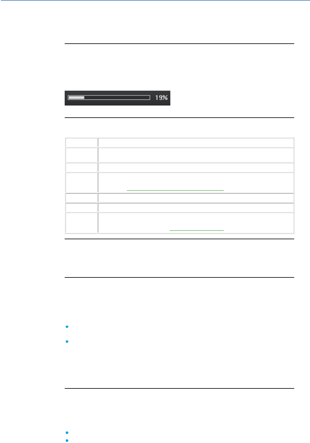
em4 soft Online Help
186
Overview
The programming workshop can be enhanced with additional function blocks called
application-specific functions.
What is an Application-Specific Function?
An application-specific function is an optional function which can be added to the
function bar and introduced into an application in the form of function blocks. If an
application-specific function is used in an application, its description file must be
written in the controller. Each description file uses a space in the controller memory,
which is characterized by a progress bar at the the bottom right of the screen.
Example: HIGH SPEED COUNT is an application-specific function.
How to Access Application-Specific Functions
To access the application-specific functions, proceed as follows:
Step
Action
1
Install the software containing the desired application-specific functions in the installation
directory of the programming workshop.
2
Launch the programming workshop.
3
Select Menu: Controller / List of application-specific functions / In the em4 soft
application...
Result: The List of available application-specific functions( § 1.4.3.1.9 ) window appears.
4
Select the application-specific functions which should appear in the function bar.
5
Open or create an application.
6
Click on the APP tab, where most of the application-specific functions are located.
Result: The application-specific functions appear. The desired function blocks can be
inserted in the wiring sheet (see Inserting Function Blocks( § 1.4.3.1.2 )).
Application-Specific Function Help
Each application-specific function has its own help. This help can be accessed by
double-clicking on the application-specific function in the wiring sheet then clicking on
the Help button in the Settings window.
Maximum Number of Slots
Each controller has a maximum number of slots that can be used by the application-
specific functions. A progress bar indicates the amount of memory used by the
application compared to the controller memory.
When the user places an Application-Specific function block on the wiring sheet,
there are two possible scenarios:
If the application-specific function is already present in the application, the
progress bar does not move.
Otherwise the progress bar indicates the new memory occupancy.
Example: The Heat curve application-specific function occupies approximately 1%
and that of the Swimming pool filtration application-specific function occupies
approximately 5%. If an application contains several Heat curve function blocks and
several Swimming pool filtration function blocks, they use approximately 6% of the
memory.
List of Available Application-Specific Functions Window
The list of application-specific functions installed is accessible via Menu:
Controller / List of Application-Specific Functions / In the em4 soft
application...
The information displayed is described below.
Function name: This is the name that appears in the function help balloon
Gen num: Unique number identifying the function
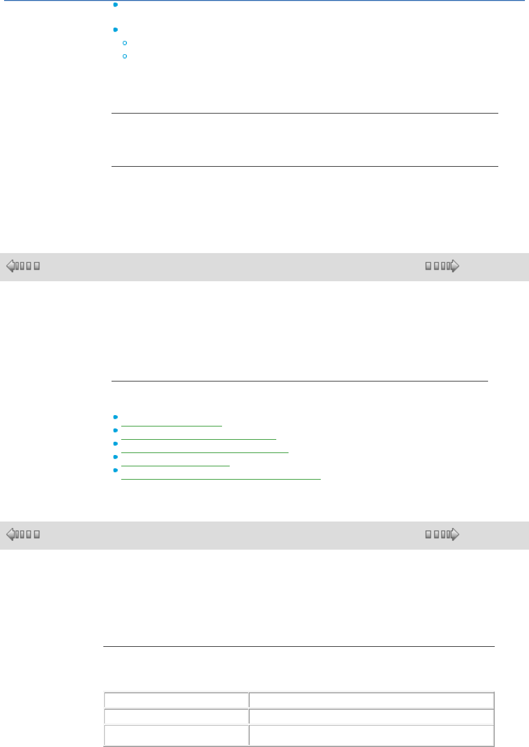
em4 soft Online Help
187
Version: Version of the function. The version of the controller software with which
the function is compatible is indicated in brackets
Loadable binaries:
If YES, the application-specific function can be used on a compatible controller.
If NO, the function can be used to construct programs and simulate them but not
to write them in the controller. (bm4 file missing)
The Add button is used to add a function to the function bar
The Delete button is used to delete a function from the function bar
Writing to the Controller
The application-specific function description file is transferred to the controller at the
same time as the application.
How to See the Controller Application-Specific Functions
To have the list of controller application-specific functions select Menu: Controller /
List of application-specific functions In the controller...
1.4.3.2 Manipulating FBD Objects
( § 1.4.3.1.9 )
( § 1.4.3.2.1 )
At a Glance
Subject of this Section
This section describes the manner in which objects in the wiring and supervision
sheets should be manipulated: how to select, move, duplicate or delete objects,
etc.
What's in this Section?
This section contains the following topics:
How to Select Objects( § 1.4.3.2.1 )
How to Create Composite Objects( § 1.4.3.2.2 )
How to Delete and Duplicate Objects( § 1.4.3.2.3 )
How to Position Objects( § 1.4.3.2.4 )
How to Create, Modify or Archive a MACRO( § 1.4.3.2.5 )
1.4.3.2.1 How to Select Objects
( § 1.4.3.2 )
( § 1.4.3.2.2 )
Overview
In a wiring or supervision sheet, function blocks, MACROS and drawings are objects.
When objects are created, it is sometimes necessary to select certain ones in order to
position or group them, etc. The selection or deselection of objects is therefore a basic
operation when creating an FBD program.
How to Select One or More Objects
The table below describes the operations to carry out in order to select one or more
objects.
If you would like to select...
Then
an isolated object.
Left-click on the object.
Several contiguous objects.
Frame the objects to be selected by defining a selection zone.
Result: All the selected objects are highlighted by small colored
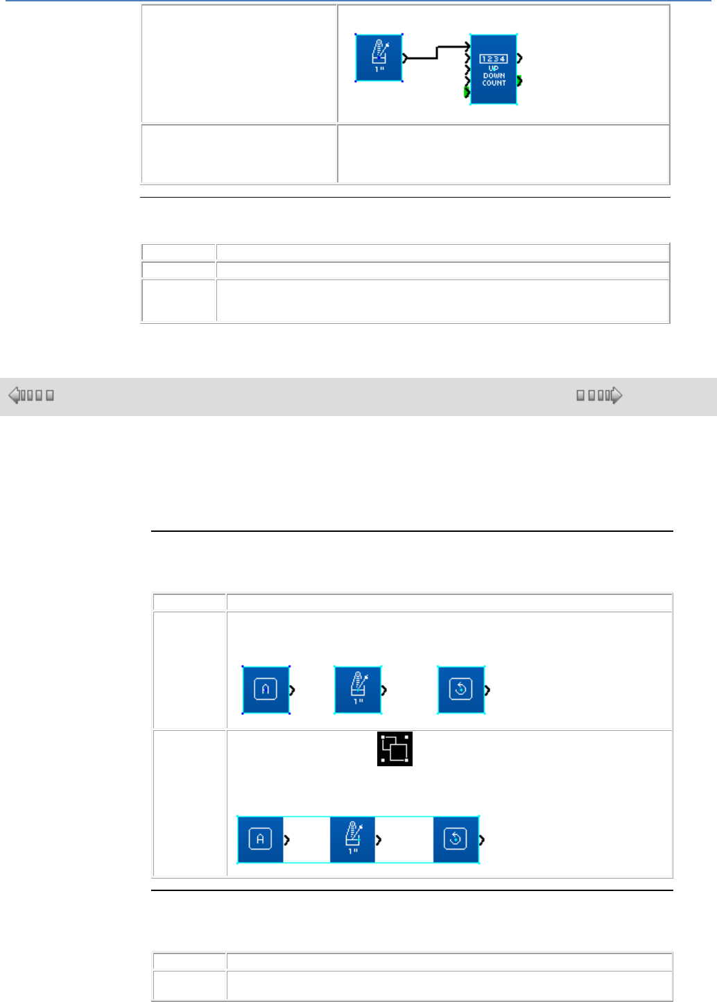
em4 soft Online Help
188
squares located at each corner of the block.
Several objects scattered about in the
wiring sheet.
Press the Shift key, then click on the objects to be selected while
continuing to hold down the Shift key.
Result: All the selected objects are highlighted by small colored
squares located at each corner of the block.
How to Deselect a Block of Selected Objects
The table below describes the operations to carry out in order to deselect a block.
Step
Action
1
Press the Shift key and keep the key pressed down.
2
Left-click the selected block that you wish to deselect.
Result: The colored squares associated with the object disappear, showing that the block
is no longer included in the selection.
1.4.3.2.2 How to Create Composite Objects
( § 1.4.3.2.1 )
( § 1.4.3.2.3 )
Overview
The objects in a wiring or supervision sheet are sometimes associated to form a
single composite object. In the same way, it is sometimes necessary to ungroup a
composite object into several single objects, in order to manipulate them individually.
How to Associate a Group of Objects
The table below describes the operations to carry out in order to associate a group of
objects.
Step
Action
1
Select the objects to associate.
Result: The selection is represented by small colored squares located on each element
of the selection.
2
Activate the Group command in the Tools menu, or by right-clicking, the cursor
being on an FB.
Result: The objects are grouped into a single composite object. The resulting object is
represented by small colored squares located at each corner of the object.
How to Ungroup a Group of Objects
The table below describes the operations to carry out in order to ungroup a group of
objects.
Step
Action
1
Select the composite object to ungroup.
Result: The composite object is represented by small colored squares.
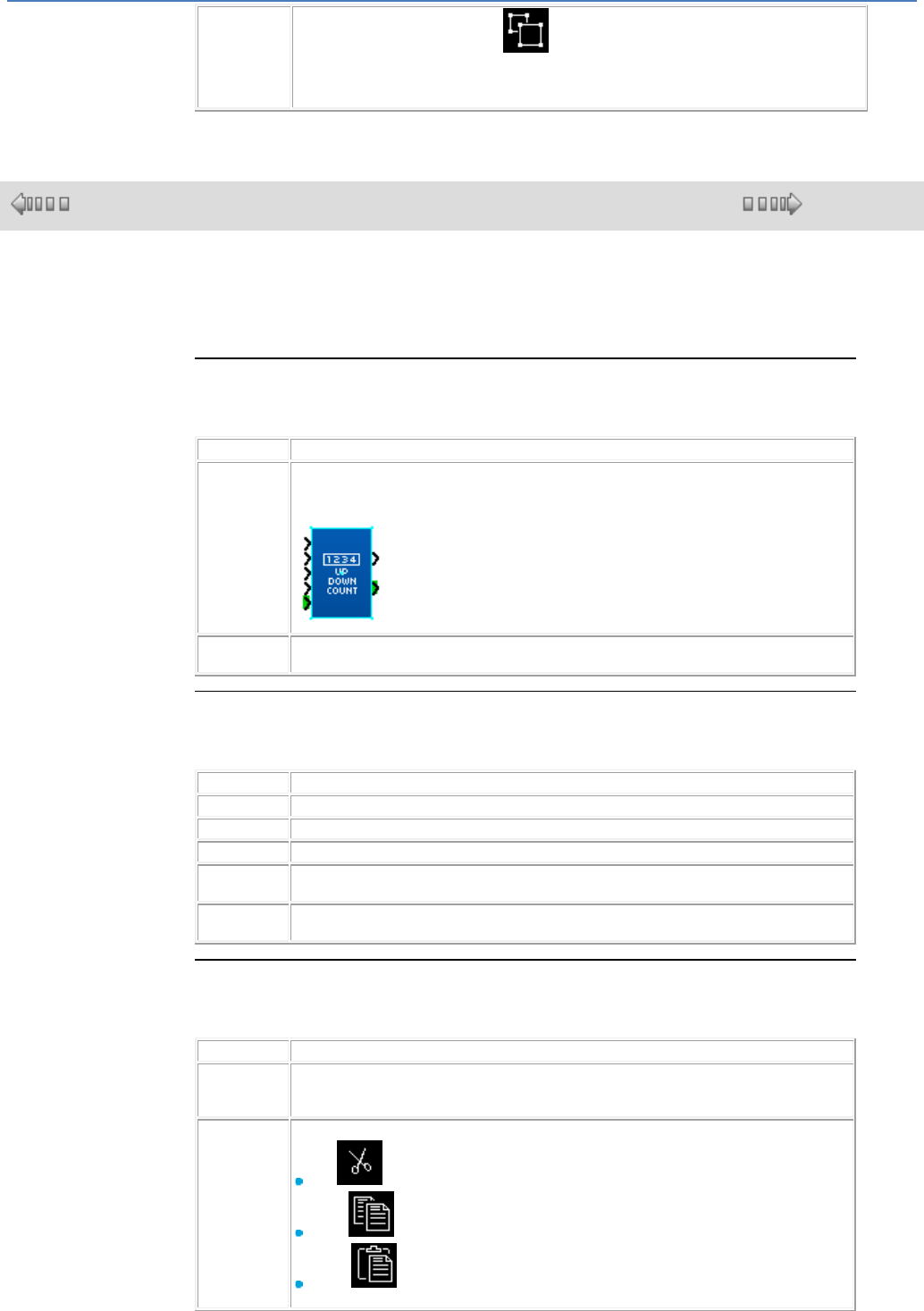
em4 soft Online Help
189
2
Activate the Ungroup command in the Tools menu, or by right-clicking, the cursor
being on an FB.
Result: All the objects contained in the composite object are displayed with their small
colored squares.
1.4.3.2.3 How to Delete and Duplicate Objects
( § 1.4.3.2.2 )
( § 1.4.3.2.4 )
Overview
Sometimes it may be necessary to delete an object or duplicate a given object in
the wiring sheet.
How to Delete Objects
The table below describes the operations to carry out in order to delete one or
more objects.
Step
Action
1
Select the object(s) to be deleted.
Result: The selection is represented by small colored squares located on each corner
of the block.
2
Press the Delete or Backspace key.
Result: The selected objects are deleted.
How to Copy Objects Using the Mouse
The table below describes the operations to be carried out in order to copy one or
more objects using the mouse.
Step
Action
1
Select the object(s) to be copied.
2
Left click on one of the selected objects.
3
Keep the mouse button pressed down and press the CTRL key.
4
Drag the selected object(s) to the chosen spot.
Result: During the movement, the selection is shown by a dotted zone.
5
Release the mouse button.
Result: The copy of the selection is positioned at the chosen spot.
How to Cut, Copy or Paste Objects
The table below shows the operations to carry out to cut, copy or paste one or
more objects.
Step
Action
1
Select the object(s) to be manipulated.
Result: The selection is represented by small colored squares located on each corner
of the block.
2
Select the command to execute, Menu/Edit or right-click on the mouse:
Cut
Copy
Paste
Result: Cut deletes the selected objects and stores them on the clipboard. Copy
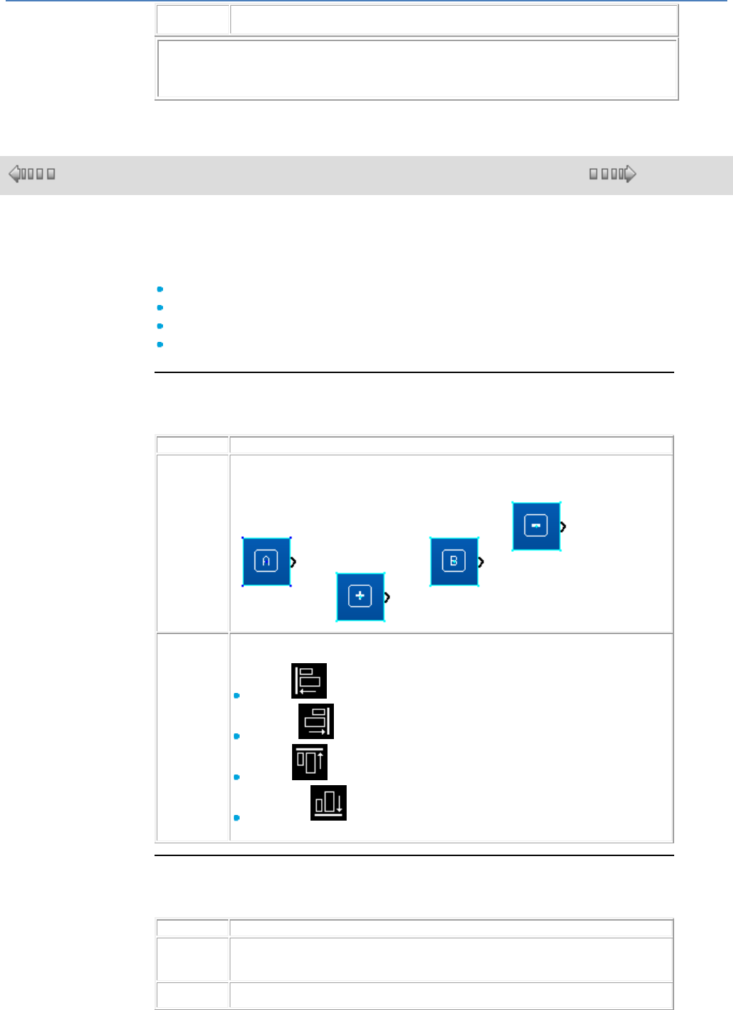
em4 soft Online Help
190
duplicates the selected objects onto the clipboard and Paste duplicates the clipboard
contents onto the screen.
Note: The keyboard shortcuts Ctrl C, Ctrl V and Ctrl X can also be used
respectively to copy the selected function blocks, and either paste or delete
them.
1.4.3.2.4 How to Position Objects
( § 1.4.3.2.3 )
( § 1.4.3.2.5 )
At a Glance
It is sometimes necessary in a wiring or supervision sheet to position an object in
relation to another.
To align objects,
To center objects,
To distribute objects
To position the objects in the foreground and background in relation to others.
How to Align a Group of Objects
The following table describes the operations to carry out when aligning a group of
objects:
Step
Action
1
Select the objects to align.
Result: All of the selected objects are highlighted by small colored squares placed at
each corner of the block.
2
From the Align command in the Tools menu, the drawing bar or by right-clicking on
the mouse, select:
Align left ,
Align right ,
Align top ,
Align bottom .
Result: The selected objects are aligned according to the choice made.
How to Center a Group of Objects
The following table describes the operations to carry out when centering a group
of objects:
Step
Action
1
Select the objects to center.
Result: All of the selected objects are highlighted by small colored squares placed at
each corner of the block.
2
From the Align command in the Tools menu, the drawing bar or by right-clicking on
the mouse, select:
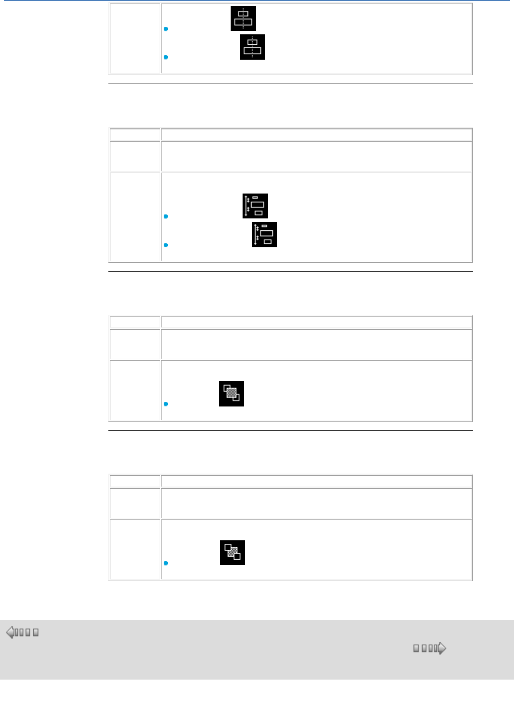
em4 soft Online Help
191
Center vertically ,
Center horizontally .
Result: The selected group of objects is centered.
How to Distribute a Group of Objects
The following table describes the operations to carry out when distributing a group
of objects:
Step
Action
1
Select the objects to distribute.
Result: All of the selected objects are highlighted by small colored squares placed at
each corner of the block.
2
From the Align command in the Tools menu, the drawing bar or by right-clicking on
the mouse, select:
Distribute vertically, ,
Distribute horizontally. .
Result: The selected group of objects is distributed.
How to Bring an Object to the Foreground
The following table describes the operations to carry out when bringing an object
to the foreground:
Step
Action
1
Select the object to be brought to the foreground.
Result: The selected object is highlighted by small colored squares placed at each
corner of the block.
2
From the Align command in the Tools menu, the drawing bar or by right-clicking on
the mouse, select:
Bring to front
Result: The object selected is brought to the foreground.
How to Send an Object to the Background
The following table describes the operations to carry out when sending an object
in the background:
Step
Action
1
Select the object to be sent to the background.
Result: The selected object is highlighted by small colored squares placed at each
corner of the block.
2
From the Align command in the Tools menu, the drawing bar or by right-clicking on
the mouse, select:
Send to back
Result: The object selected is sent to the background.
1.4.3.2.5 How to Create or Modify a MACRO
( §
1.4.3.2.
4 )
( § 1.4.3.2.6 )
What is a MACRO?
A MACRO is a group of function blocks. It is characterized by its number, its name, its links, its internal
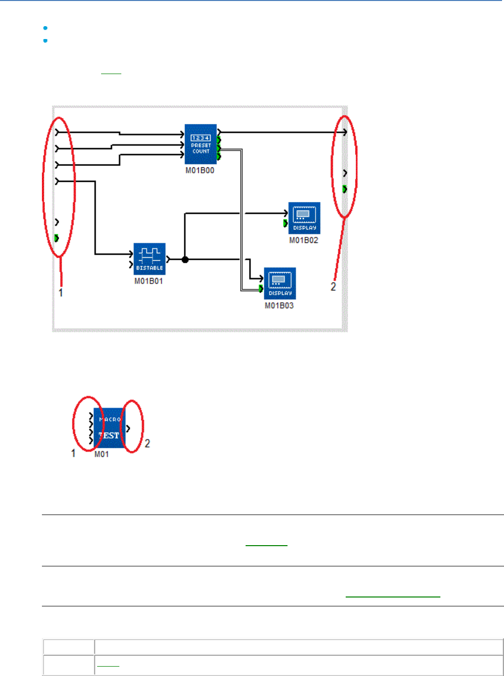
em4 soft Online Help
192
function blocks (255 maximum) and its input/output connections.
Inside the MACRO:
The input connections are each connected to one function block input maximum
Each function block output can be connected to a function block input or to an output connection.
Seen from outside, a MACRO behaves like a function block with inputs and/or outputs likely to be
connected to links( § 1.4.3.1.3 ). However, a MACRO cannot be inserted in another MACRO.
Example:
Internal view of a MACRO:
1
Input connections (each connected to one function block input maximum)
2
Output connections
External view of the same MACRO in the edit window:
1
Inputs (only the effective input connections are shown)
2
Output (only the effective output is shown)
Maximum Number of MACROS
The maximum number of MACROS (including instances( § 1.4.3.2.5 ) taht are result of a duplication) is
64 per application.
Saving a MACRO
A MACRO is saved by saving the application in which it is found (see Saving an Application( § 1.6.1.9 )).
How to Create a MACRO
A MACRO is created in several steps:
Step
Action
1
Select( § 1.4.3.2.1 ) the function blocks on the wiring sheet that you wish to appear in the MACRO.
Example:
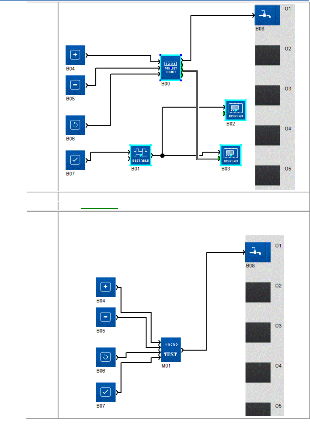
em4 soft Online Help
193
2
Select the Tools/Create a MACRO command from the pop-up menu, or right-click on Create a MACRO.
3
Fill in the Macro Properties( § 1.4.3.2.5 ) dialog box (the only compulsory field is MACRO identifier).
4
Close the dialog box by clicking on OK.
Result: All function blocks selected in step 1 are then shown by a single block (that of the MACRO) in the edit
window.
Example:
Manipulating a MACRO
Once created, a MACRO can be manipulated like a function block and in particular it can be:
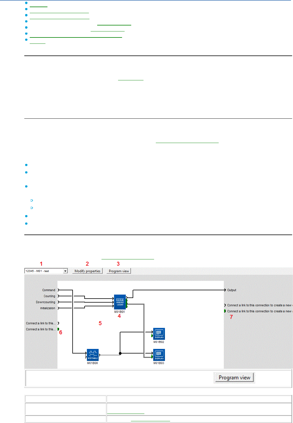
em4 soft Online Help
194
Selected( § 1.4.3.2.1 )
Associated with other objects( § 1.4.3.2.2 )
Duplicated in the Edit window( § 1.4.3.2.3 )
Imported from another workshop (import MACRO)( § 1.4.3.2.6 )
Exported out of the workshop (export MACRO)( § 1.4.3.2.6 )
Copied/cut between two Software Workshops( § 1.4.3.2.3 )
Deleted( § 1.4.3.2.3 )
But it may also be archived in the functioning workshop and be used again at a later date to create or modify a FBD application
Instances of a MACRO
A macro created by duplication is deemed to be a new instance of the original macro.
Modifications made to the graphic or properties( § 1.4.3.2.5 ) of an instance are automatically made on
other instances of the macro. They are equivalent to recompiling the macro. On the other hand,
modifications to the comment or internal function block parameters are specific to each instance of the
macro. One may thus find two instances of the same macro that have different parameters.
If the last instance of a macro is cut or deleted, a message warns the user. It is then possible to cancel
the operation.
The MACRO Properties Dialog Box
The MACRO Properties dialog box is used to enter or modify the properties of a MACRO. If the MACRO
has been duplicated, the modifications will affect all instances of the MACRO( § 1.4.3.2.5 ).
The dialog box is accessible when a MACRO is created or in the pop-up menu by selecting Display
macro then the Modify properties button.
The MACRO parameters are as follows:
MACRO identifier (1 to 5 characters)
Name of the MACRO (optionally, 25 characters maximum), the name of the Macro is visible on the edit
sheet when the cursor passes over the Macro
Symbol for the block, i.e. the appearance of the block that represents the MACRO in the main wiring
sheet, and may be any of the following:
Standard image (The MACRO identifier is then used as the block symbol), or
Custom image (To insert a custom image, click on the ... button)
Name of inputs (if necessary, modify the input label in the Label box of the table)
Name of outputs (if necessary, modify the output label in the Label box of the table)
The MACRO Window
MACROS can be modified in the MACRO window accessible from the Windows menu (except when
protected by a password. See Password Protection( § 1.4.3.2.5 )).
Note: To return to the edit window from the MACRO window, click on the button.
The table below lists the different elements in the MACRO window.
Element
Function
1: Drop-down list
Select the MACRO from the list of all the project MACROS and, if applicable, from the
different instances( § 1.4.3.2.5 ).
2: Modify properties button
Access the MACRO Properties( § 1.4.3.2.5 ) dialog box.
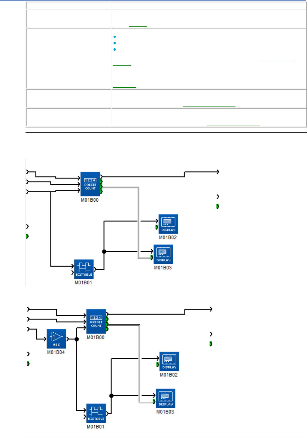
em4 soft Online Help
195
3: Program View button
Access the main programming sheet by clicking on it.
4: Function block internal to the
MACRO
Access the internal function block parameters by double-clicking on them.
(If the MACRO has been duplicated, the parameter modifications will only affect the
current instance( § 1.4.3.2.5 ) of the MACRO).
5: MACRO wiring sheet
Modify the graphic of the MACRO and in particular:
Add or delete a link between two function blocks
Add a function block from the function bar or from the edit window
Delete a function block
(If the MACRO has been duplicated, these modifications will affect all instances of the
MACRO( § 1.4.3.2.5 )). If the macro is archived, the Workshop offers the user the
opportunity to create a macro with a new ID in the edited application, but does not modify
the archived macro).
It is not possible to connect two input connections to the same function block input (see
Design Tip( § 1.4.3.2.5 )).
6: Input not connected
Create a new link to the input of a function block on the wiring sheet. An additional input of
the MACRO will then appear in the edit window. (If the MACRO has been duplicated,
these modifications will affect all instances of the MACRO( § 1.4.3.2.5 )).
7: Output not connected
Create a new link from the output of a function block on the wiring sheet. An additional
output of the MACRO will then appear in the edit window. (If the MACRO has been
duplicated, these modifications will affect all instances of the MACRO( § 1.4.3.2.5 )).
Design Tip
Inside a Macro, it is not possible to connect two input connections to two inputs on different function
blocks.
Instead, we recommend adding a digital or analog YES function as appropriate.
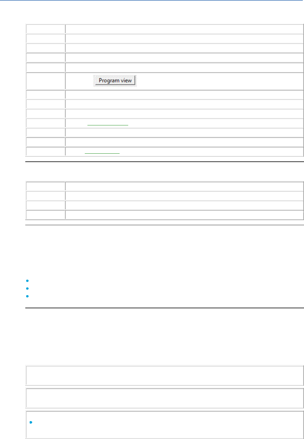
em4 soft Online Help
196
How to Modify the Graphic of an Instance of a MACRO While Retaining Other Instances
Modifying the graphic of a single MACRO instance essentially means creating a new MACRO. Follow the
steps below:
Step
Action
1
Select the MACRO instance by right-clicking the mouse.
2
Select Display MACRO in the pop-up menu.
3
Select Menu: Edit Select all.
4
Select Menu: Edit Copy.
5
Click on the button to return to the main wiring sheet.
6
Select Menu: Edit / Paste.
7
Reposition the selection if necessary.
8
Select Create a MACRO in the pop-up menu.
9
Fill in the MACRO Properties( § 1.4.3.2.5 ) dialog box (the only compulsory field is MACRO identifier).
10
Close the dialog box by clicking on OK.
11
Select Display MACRO in the pop-up menu.
12
Use the MACRO window( § 1.4.3.2.5 ) to create the I/O connections and make modifications.
How to Modify a MACRO Comment
To modify a MACRO comment, proceed as follows:
Step
Action
1
Double-click on the MACRO
2
Modify the comment.
3
Confirm by clicking on OK.
Password Protection
A password may if necessary be used to protect the MACROS of a project. It is independent of the
application password. It is a 4-digit number (0000 is not a valid password).
This protection is defined in the program configuration window accessible via the PROGRAM button or
via Menu: File Properties, Configuration tab.
The same password protects all project MACROS. It is requested when the project is opened.
If the password is not entered when the project is opened the following functions are not available:
Access to the MACRO window
Copy a MACRO
Print MACROS
Archiving a Macro
Once created, the Macro may be archived in the workshop. It may then be re-used as a function block to
create or modify an application when using the workshop at a later date.
To archive a Macro, select it with left-click and Drag/Drop it from the wiring sheet to the function bar's
MACRO tab. It then appears in the Macro tab as a block available for programming. Drag/Drop it from the
function bar to the wiring sheet in order to use it in a FBD program. The parameters for each function
contained in the macro are the parameters of the example that has been archived.
Note 1 : if the wiring sheet already contains an example of the same Macro when it is
Dragged/Dropped from the function bar, a new example appears in the wiring sheet.
Note 2 : A user may not archive a Macro with the same ID as a Macro that has already been archived.
To do this, he must change the Macro's ID.
Note 3 : If an open program contains a Macro ID identical to a Macro archived in the workshop:
If the two Macros are identical (identical FBD network, different block function parameters and
comments) the archived Macro is accessible from the function bar.
em4 soft Online Help
197
If the two Macros are different (different FBD network) the archived Macro is not accessible from the
function bar and is shown greyed out.
To delete a Macro from the archive, it is necessary to display the content of the function bar's MACRO
tab, select the Macro's symbol in the function bar by right-clicking on the mouse, and select Delete in the
contextual menu or press the Delete key. It disappears from the MACRO tab in the function bar but it
does not disappear from the FBD application being edited.
Note 4 : The Macro is also removed from all the function bar's customizable tabs
To reconfigure an archived Macro, it is necessary to display the content of the function bar's MACRO tab,
select the Macro's symbol in the function bar by right-clicking on the mouse and select Reconfigure in the
contextual menu. The “Macro configuration” window opens.
If the user modifies the name of the archived Macro or the input output labels, this affects the archive
but not the examples used in the wiring sheet.
If the user modifies the ID of the archived Macro or its symbol, the user is informed by the workshop
that he is in the process of creating a new archived MACRO and is going to replace the old Macro in
the archives. However, this modification only affects the archive, not the examples used on the wiring
sheet.
Note 5 : the user may then re-archive the old Macro by using one of the examples still on the wiring
sheet. This allows him to create a new macro based on an existing macro.
1.4.3.2.6 How to import or export a MACRO
( § 1.4.3.2.5 )
( § 1.4.3.3 )
Import a MACRO
The File Import Macro command can be used to import a macro exported as
mm4 file. The macro is added in the function bar (displayed with any FBD program)
How to import a MACRO
MACROS are imported as follows :
Step
Action
1
Select the Menu: File Import MACRO.
2
Select the .mm4 file corresponding to the MACRO to import. (The MACRO to import is
named with its ID).
During import some checks are made.
If the MACRO is compliant with the workshop and if no MACRO with the
same ID already exists in the workshop then the MACRO is imported and
added in the function bar (displayed with any FBD program).
If the MACRO is not compliant with the workshop a message is displayed.
The import is canceled.
If a MACRO with the same ID already exists the user must choose to
continue or to cancel the action.
Export a MACRO
The user can export only MACROS present in the "MACRO" tab of the function bar
(displayed with any FBD program).
How to export a MACRO
MACROS are exported as follows :
Step
Action
em4 soft Online Help
198
1
Edit a FBD program.
2
Choose "MACRO" tab from the function bar.
3
Right-click on the MACRO to export then choose "Export".
4
Select the folder to export to.
The exported MACRO is a .mm4 file named with the ID of the MACRO.
The exported MACRO can be then imported in another workshop.
The MACRO can be exported with an associated help in PDF format, right-click on
the MACRO to be exported and select "Reconfigure", "Associated Help"
1.4.3.3 Debugging / Monitoring an FBD Application in the Programming Workshop
( § 1.4.3.2.6 )
( § 1.4.3.3.1 )
At a Glance
Subject of this Section
This section describes the different functions linked to debugging the application
in the programming workshop.
What's in this Section?
This section contains the following topics:
Simulation Mode( § 1.4.3.3.1 )
Debugging Mode( § 1.4.3.3.2 )
Modification and Forcing in Simulation and Debugging Mode( § 1.4.3.3.3 )
1.4.3.3.1 Simulation Mode
( § 1.4.3.3 )
( § 1.4.3.3.2 )
Introduction
Before loading a program onto a controller, it is possible to simulate execution
using the programming workshop.
Access and Control
See: How to Debug an Application Without Loading it onto the Controller:
Simulation( § 1.2.7 ).
Modification and Forcing
See: Modification and Forcing in Simulation and Debugging Mode( § 1.4.3.3.3 ).
1.4.3.3.2 Debugging Mode
( §
1.4.3.3.1 )
( § 1.4.3.3.3 )
Overview
In debugging mode, the controller is linked to the software workshop's host computer. In this mode
you can perform the following actions from the edit and supervision windows and from the front panel:
View the states of function block outputs
View and modify function block parameters

em4 soft Online Help
199
Force the state of function block inputs and outputs (maximum of 10 function block outputs
simultaneously)
Modify the state of the buttons on the front panel
Force the state of function block links
Monitoring mode can be accessed from the Mode:Debugging menu.
In debugging mode, the different windows are all updated on each cycle. For example, if a function
block is placed in the edit and supervision window, when any action is performed on this function
block from the edit window, it is also updated in the supervision window.
(See How to Monitor and Modify an Application Running on the Controller from the Programming
Workshop: Debugging( § 1.2.8 ))
Unavailable Functions
In debugging mode, the following functions are not available:
Graphic editing of programs
Transfer program
Delete program
Compare program
Switch to Simulation mode
Modify communication parameters
Access to Debugging Mode
Debugging is accessed by the Mode: Debugging menu or by using the icon.
The following scenarios may arise:
An application is open in the programming workshop: the version on the controller is compared
with that of the programming workshop:
If the programming workshop application is the same as the application on the controller,
Debugging mode is started.
If the programming workshop application is different from the application on the controller, the
versions must be synchronized by transferring the PC program to the controller or the controller
program to the PC.
No application is open in the programming workshop: in this case, the programming workshop
offers to send the application currently being executed on the controller back to the PC.
Diagram
The program states in the application windows are represented the same way as those in Simulation(
§ 1.4.3.3.1 ) mode.
The figure below shows an example of edit and supervision windows in simulation mode:
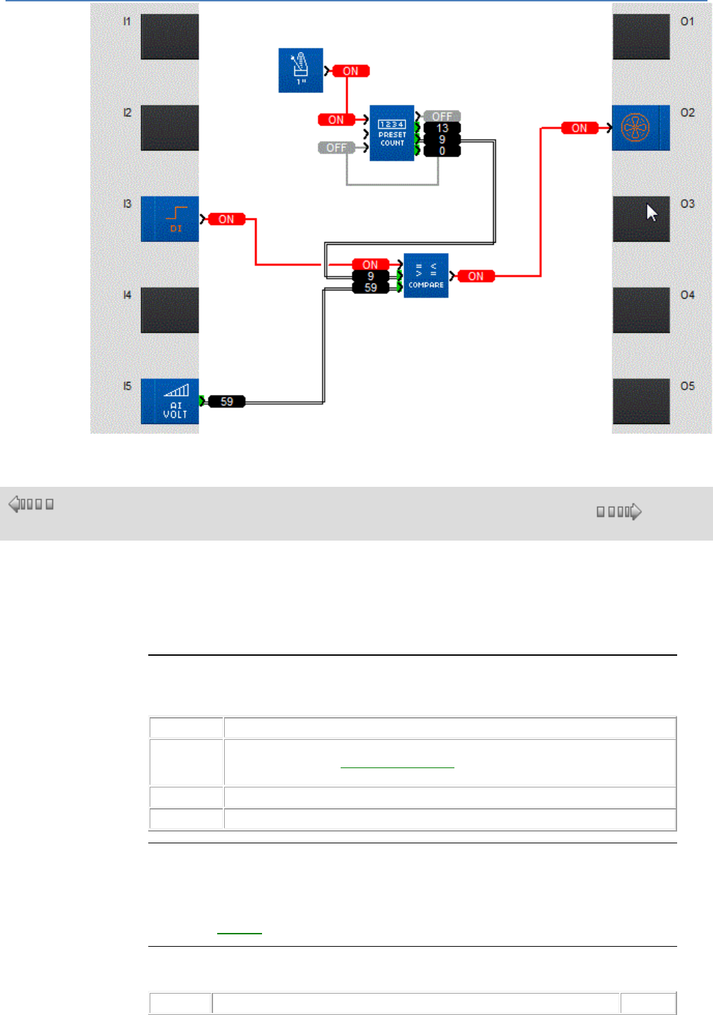
em4 soft Online Help
200
1.4.3.3.3 Modification and Forcing in Simulation and Monitoring Mode
( § 1.4.3.3.2
)
( § 1.4.4 )
Overview
In simulation or debugging mode, you can modify the parameters of function blocks
and inputs, and force link states.
Forced values are highlighted by a change in color according to the state.
How to Modify the Parameters of a Function
During simulation or debugging, it is possible to modify the parameters of a function in
the Edit window or in the window of a MACRO.
Step
Action
1
Double-click on the symbol representing the function. (This operation can be performed in
the edit window, in the function summary table( § 1.2.7 ) or in the supervision window.)
Result: The function parameter window opens.
2
Modify one or more function parameters.
3
Click on OK.
How to Modify or Force Discrete Inputs
During simulation or monitoring, it is possible to modify or force discrete inputs by
clicking on them with the mouse. Each click reverses the state of the input.
In debugging mode, this action corresponds to forcing. It is maintained until the
moment of release( § 1.4.3.3.3 ).
How to Modify or Force Analog Inputs
During simulation or debugging, it is possible to modify or force analog inputs.
Mode
Procedure(s)
Result

em4 soft Online Help
201
Simulation
Method 1:
Click on the input with the mouse.
Modify the value in the Analog Value window.
The
simulate
d input
value is
modified
until the
moment
of
release(
§
1.4.3.3.3
).
Method 2:
If the input has already been modified, release forcing( § 1.4.3.3.3 )
Click on the button.
Result: A potentiometer (in volts or % depending on the input configuration)
(15 potentiometers maximum) appears for each analog input.
Click on the cursor and move it while holding down the left mouse button.
The
simulate
d input
value is
modified.
Debuggin
g
Click on the input with the mouse.
Modify the value in the Analog Value window.
The input
value is
forced
until the
moment
of
release(
§
1.4.3.3.3
).
How to Force a Discrete Link
During simulation or debugging, it is possible to force a discrete link in the Edit window
or a discrete link between two objects in the window of a MACRO( § 1.4.3.3.3 ).
To force a discrete
link...
proceed as follows:
Result:
Momentarily...
Click on the link.
The state of the link is momentarily
reversed.
Permanently...
Click on the link with the right
mouse button.
Click on Force and maintain.
Choose the state into which the link
should be forced.
The link remains in the chosen state
until the moment of release( §
1.4.3.3.3 ).
How to Force an Analog Link
During simulation or debugging, it is possible to force an analog link in the Edit window
or an analog link between two objects in the window of a MACRO( § 1.4.3.3.3 ).
To force an analog
link...
proceed as follows:
Result:
Momentarily...
Click on the link.
Enter the value to which the link
should be forced.
The link remains at the chosen value
until a system or user action causes its
modification.
Permanently...
Click on the link with the right
mouse button.
Click on Force and maintain.
Enter the value to which the link
should be forced.
The link remains in the chosen state
until the moment of release( §
1.4.3.3.3 ).
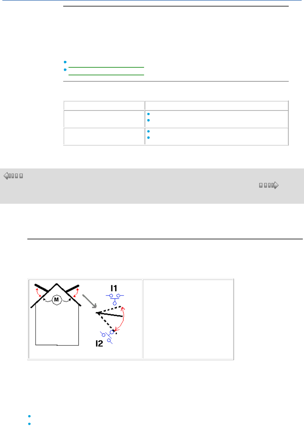
em4 soft Online Help
202
Forcing a Link in a MACRO
During simulation or debugging, it is possible to force a link in the window of a MACRO
on condition that it is a link between two MACRO function blocks or from a function
block to an output. It is not possible to force a link connected to a MACRO input.
To open the MACRO window, right-click on the MACRO then select Display
MACRO in the pop-up menu.
See, according to the type of link:
How to Force a Discrete Link( § 1.4.3.3.3 )
How to Force an Analog Link( § 1.4.3.3.3 )
How to Release Forcing
The forced links(s) and forced inputs can be released in the following manner.
To release...
proceed as follows:
a link or an input ...
Click on the link or input with the right mouse button.
Click on Release.
all forced links and forced inputs ...
Click on the wiring sheet with the right mouse button.
Click on Release all.
1.4.4 Example of an FBD Application
( §
1.4.3.3.
3 )
( § 1.5 )
Description
This example describes how a greenhouse's window panes can be managed automatically.
Specifications
The owner of a greenhouse would like to acquire an installation to manage the opening and closing of the
ventilation window panes located on the greenhouse roof.
The greenhouse has two window panes to provide ventilation. The opening of these window panes is
controlled by a motor and 2 sensors that indicate whether the window panes are open or closed:
Window pane open
Window pane closed
During the day, the window panes open to ventilate the structure from 12:00 to 15:00, at the time of day
when, in principle, the temperature is the highest. However, if the temperature is less than 10ºC, the
window panes do not open, or when they are already open, they close.
In addition, the window panes open during the day when the temperature reaches 25ºC. If the
temperature falls below 25 ºC, the window panes must close again.
Finally, at night, the window panes remain closed regardless of the temperature.
Program description, 3 time ranges are used:
Range 1: Night, from 21:00 to 07:00
Range 2: Day, from 07:00 to 12:00 and from 15:00 to 21:00
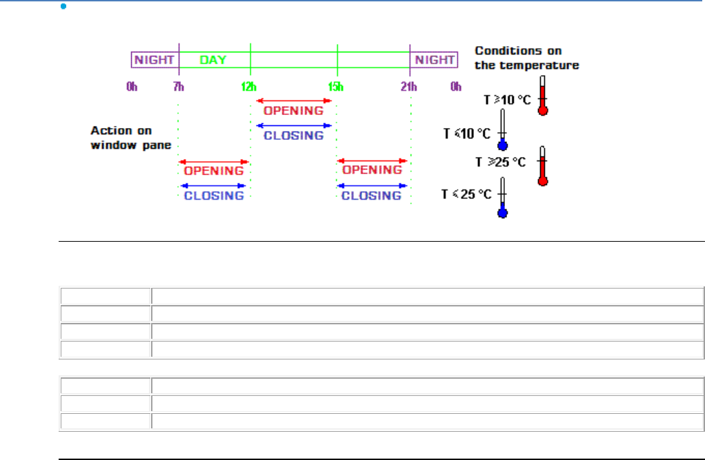
em4 soft Online Help
203
Range 3: Noon, from 12:00 to 15:00
Summary:
Input/Output Table
Description of the inputs:
Input
Description
I1
Window panes open (Discrete)
I2
Window panes closed (Discrete)
I5
Temperature (analog)
Description of the outputs:
Output
Description
O1
Opening of the window panes (Discrete)
O2
Closing of the window panes (Discrete)
The temperature is supplied by a sensor with output voltage of 0 to 10 V.
FBD wiring sheet
Description:
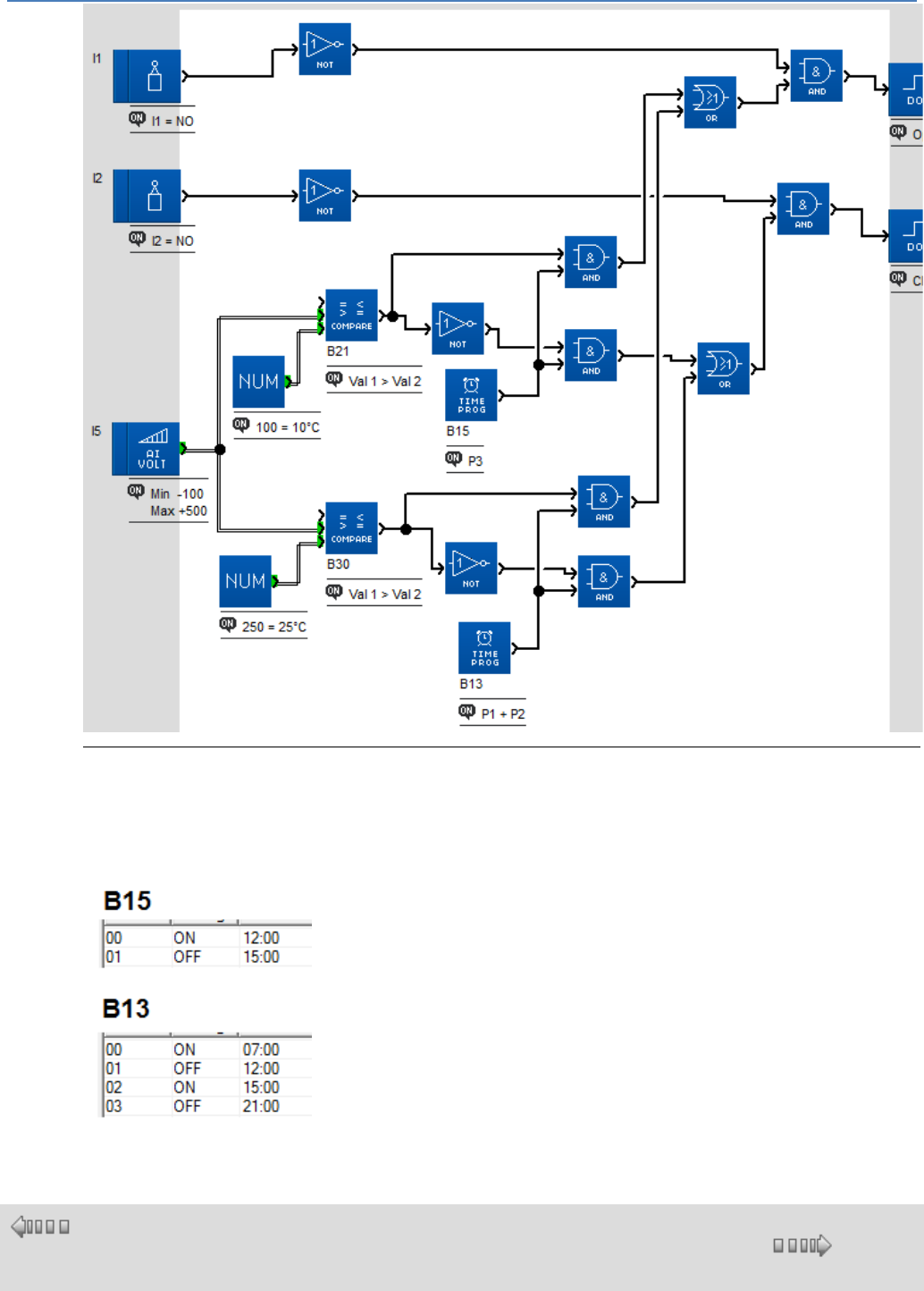
em4 soft Online Help
204
Description of the Parameters
Analog comparator B21
Value1 > Value2
Analog comparator B30
Value1 > Value2
Daily programmer B15, B13
1.5 Controller Connections
( § 1.4.4
)
( § 1.5.1 )
em4 soft Online Help
205
At a Glance
Subject of this Section
This section describes the functions and parameters related to connection to the controller.
What's in this Part?
This part contains the following chapters:
Connection with the Programming Workshop( § 1.5.1 )
Communication via the Modbus accessory( § 1.5.2 )
Communication via the Ethernet connection( § 1.5.3 )
Communication via the 2G connection( § 1.5.4 )
This table indicates the various options according to the type of communication:
read/write an
application
write
Firmware
Debugging :
read/write
Monitoring :
read/write
XBIN, XBOUT, XWIN,
XWOUT
USB accessory
X
X
X
Bluetooth accessory
X
X
X
RS485 accessory
X
2G SMS networked base
X
2G e-Connect networked base
X
X
X
X
1.5.1 Connection with the Programming Workshop
( § 1.5 )
( § 1.5.1.1 )
At a Glance
Subject of this Chapter
This chapter describes the different functions related to the connection of the controller
to the programming workshop.
What's in this Chapter?
This chapter contains the following topics:
Configuring Communication Between the Programming Workshop and the
Controller( § 1.5.1.1 )
Transferring the Program from the PC to the Controller( § 1.5.1.2 )
Read in the Controller( § 1.5.1.3 )
ON/OFF Program Run Commands( § 1.5.1.4 )
Compare the Controller Data with the Program( § 1.5.1.5 )
Controller Diagnostics( § 1.5.1.6 )
Protection of the Program Saved on the Controller( § 1.5.1.7 )
Clear the Program Contained in the Controller( § 1.5.1.8 )
Read/Write date and time( § 1.5.1.9 )
Configuring the Controller Language( § 1.5.1.10 )
Update the Controller Software( § 1.5.1.11 )
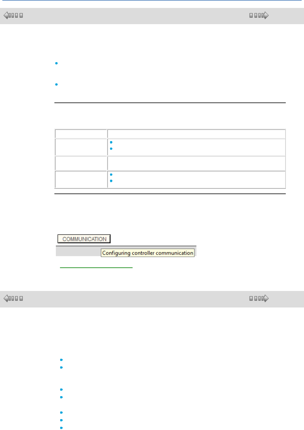
em4 soft Online Help
206
1.5.1.1 Configuring Communication Between the Programming Workshop and the Controller
( § 1.5.1 )
( § 1.5.1.2 )
Description
To establish communication between the programming workshop and the controller, one
of the following links can be used:
With the accessory :
- USB communication
- Bluetooth communication
With a networked base :
- 2G e-Connect communication
Prior Action
Before launching the connection between the programming workshop and the controller,
check the following elements:
If using...
ensure that:
a USB link
The controller is physically connected to the programming workshop (PC).
The connection is correctly configured.
a Bluetooth link
The Bluetooth adapter and its driver have been installed.
Note: : The driver assigns a com port to the adapter.
a 2G link
A SIM card is present.
An aerial is present.
Access
For the accessory: The Configuring the Connection... function can be accessed from
the menu: Controller/Configure Connection.
For the networked base: click on the COMMUNICATION button on the edit sheet.
A Configuring Communication( § 1.5.4.3 ) window appears.
1.5.1.2 Transferring the Program from the PC to the Controller
( § 1.5.1.1 )
( § 1.5.1.3 )
Description
The Write to the controller function translates the program into data that can be
loaded into the controller and transfers it from the PC to the controller.
This command opens the window: Compilation results, if the result of the
compilation is:
Compilation successful, then the application is transferred to the controller,
Failed, the error number appears, the program must be edited, the error corrected
and the write command launched again.
The transfer is only possible if the controller:
Is not blocked by having sent an incorrect password,
Is stopped.
The program will be written on the controller only in the following cases:
The controller does not contain a program,
The controller contains a program that is not read/write protected with a password,
The controller contains a program that is read/write protected with a password, and
em4 soft Online Help
207
the password is known.
(In this case, the Password dialog box appears).
If all conditions are met, the Write options( § 1.6.1.4 ) dialog box appears.
Note: Only an FBD program that has been compiled without any error will be
written to the controller.
Note: The type of controller declared in the program must be compatible with the
controller connected:
Hardware version of the controller,
controller firmware version,
Controller software build number less than or equal to that of the controller,
Same extension,
Same hardware version and same extension software version.
Note: The controller software is implicitly updated when a program is transferred to
a controller containing different software.
The controller software update is only allowed when the software loaded is
designed for the same controller:
Same hardware version,
Same boot version and build number less than or equal to the boot of the
controller to be loaded.
Access
The Write to the controller function can be accessed from the Controller
menu.
Controller default software
If a communication problem appears (3 attempts), then you can try loading the
controller firmware with the menu: Controller/Update the Controller Firmware
and Language( § 1.5.1.11 )
(Check that the serial line is not disturbed).
Procedure
Procedure for transferring the program to the controller:
Step
Action
1
Activate the menu Controller:Write to the controller.
Result: The program checking is launched and the Compilation results window opens.
2
Depending on the results of the check:
Compilation successful: Confirm with the OK key.
Result: The Write Options dialog box appears.
Failed: Correct the errors and then start again at step 1.
3
Select Write Options( § 1.6.1.4 ):
Protection of the program saved on the controller( § 1.5.1.7 ): Protect reading and
modification of the program with a password.
Save modifications before writing,
Start debugging mode and switch on the controller.
4
Confirm your changes by pressing the OK key.
Result: The Write Options dialog box disappears.
5
Start the transfer by pressing on the OK key.
1.5.1.3 Read in the Controller
( § 1.5.1.2 )
( § 1.5.1.4 )
Description

em4 soft Online Help
208
The Read in controller function translates the data contained in the controller in order
to restore a program that can be edited in the programming workshop.
The programming workshop will be able to read the contents only if the controller:
Contains a program that is not read/write protected with a password, or,
Contains a program that is read/write protected with a password, and the password
is known.
(In this case, the Password dialog box appears).
The data retrieved by reading contains references to the application during its transfer:
The name of the application file,
The access path: relative to the File:Preferences... work directory.
Note: The access path is limited to a maximum of 128 characters (program name
with extension included).
If this limit is exceeded (only the file name and its extension are saved), then a
window is displayed to prompt the user to complete the access path.
Access
The Read in the controller function can be accessed from the Controller menu.
Restoring the Program
Using the information concerning the application present on the controller (name of the
source file and location on the PC), the workshop tries to reload the application file
from the PC.
The aim of this search is to retrieve the graphic representations:
Positions related to the function blocks,
Positions of links between functions,
Comments,
Screen backgrounds,
Drawings.
Note: Modifications may have been made after the write from the application to the
controller if:
At the level of the programming workshop: the application has changed,
At the controller level: modification of the parameters using the front panel.
In the case where differences in parameters appear, the dialog box asks the user if
s/he would like to update the programming workshop program with the parameters
read in the controller.
There are certain cases where the program cannot be retrieved:
Program differences appear between the file containing the program on the PC and
the application read on the module,
The file containing the program on the PC is not accessible.
To reread the original application saved on the PC, use the path (128 characters) in
the configuration of the application loaded on the controller, then try an absolute
path, then a path relative to the one defined as a preference. If only the name.ext
can be found, look for the name in the preferences directory, or ask the user to
pinpoint the location of the file for you.
In these circumstances, the Program construction window opens and suggests an
alternative procedure:
Construction using the file specified by the user: the user manually enters the
file path of the application to be retrieved.
Automatic construction of the program: in this case, the programming workshop
interprets the data retrieved on the controller and rebuilds the corresponding
application (the file is regenerated).
Note: The program loaded into the controller does not contain information
concerning page setup (drawing, comment, relative position of the function blocks
and links); a default page setup is thus produced.
Note: All of the function parameters are retrieved.
em4 soft Online Help
209
1.5.1.4 ON/OFF Program Run Commands
( § 1.5.1.3 )
( § 1.5.1.5 )
Description
These commands can be used to remotely control a controller connected to the PC.
Once the connection has been made, control can be carried out using the front panel
window, with which the user can interact as if it were the actual front panel of the
controller.
This function is used to start and stop the program in the controller:
Start controller and Reset saved parameters : all the current values
(counters, timers, etc.) are reset to zero before the start up of the program,
Start the controller without Reset : the actual values for which the Save on
power break option were activated are maintained,
Turn the controller off : the program no longer runs, the outputs are
deactivated.
Access
The ON/OFF Program Run Commands can be accessed from the Controller menu.
Controller Status Upon Power Failure
In the event of a power failure, the program is immediately stopped, parameters of the
type initialization on power break or latching on power break are saved.
(See How the controller behaves in the event of power outage( § 1.2.20 )).
A break in the link between the workshop and the controller is indicated in the
workshop by an error message (if the workshop is in Debugging mode, it switches to
Edit mode).
When power is restored, the controller itself executes an ON command, initializing
only the non-saved data.
Controller Status on Blocking Error
If the event of a controller blocking error (break or disruption in the link between the
module and its extensions), the controller places itself in OFF mode:
The cause of the blockage can be viewed on the front panel of the controller.
To restart the controller, having removed the reason for the blockage, simply use the
Start controller and Reset saved parameters command.
See What the error code displayed on the front panel of the controller means(
§ 1.2.9 ),
1.5.1.5 Compare the Controller Data with the Program
( § 1.5.1.4 )
( § 1.5.1.6 )
Description
This function tests the identity between the data contained in the controller and the
data produced by compiling the programming workshop's application.
If the controller's data is protected by a password, the user is prompted to enter it in
the Password window.
The comparison is carried out on the program (including parameters) contained:
In the controller
em4 soft Online Help
210
In the programming workshop edit window on the PC.
Access
The Compare the controller data with the program function can be
accessed from the Transfer menu.
1.5.1.6 Controller Diagnostics
( § 1.5.1.5 )
( § 1.5.1.7 )
Description
The diagnostics function allows you to view all characteristics of the controller to
which the programming workshop is connected.
The Controller diagnostics dialog window can only be accessed if the controller is
connected to the PC.
The diagnostics window is made up of 2 tabs:
Hardware: characteristics of the controller (hardware and software),
Application: Characteristics of the application built into the controller (user
program).
Access
The Controller diagnostics function can be accessed from the Controller
menu.
Hardware
The hardware tab provides the following information:
The controller type and version/release of the hardware and software,
Numbers and types of controller inputs and outputs,
connected extension(s) and version(s)/release(s), only for the extendable
controllers,
Controller status (On, Off, Blocked in Error, Warning),
Controller language,
Error code (No error, Binary fault, Communication fault, Target Error or Warning),
Note: The hardware-related information is always accessible, regardless of
whether the program is protected by a password.
Application
The application tab provides the following information:
The name of the program, its author, and version,
Memories used/maximum memories,
All of its configuration parameters: Basic cycle time, WATCHDOG action,
Password
Note: The information relating to the application is only available if the controller
contains a program that is not password-protected or if the user knows the
password.
1.5.1.7 Protection of the Program Saved on the Controller
( § 1.5.1.6 )
( § 1.5.1.8 )
em4 soft Online Help
211
Description
The option for protecting the program transferred to the controller can be activated at
the end of the Write to the controller procedure( § 1.5.1.2 ).
The protection is activated in the Write options dialog box that contains the
parameter: Protect reading and modification of the program with a
password: if this option is validated, the password data entry zones are activated.
Note: After 5 unsuccessful tries, the module is locked for a duration of 30 minutes.
1.5.1.8 Clear the Program Contained in the Controller
( § 1.5.1.7 )
( § 1.5.1.9 )
Description
The program's clear function can be used to erase the application loaded on the
controller, as well as related information (password), but does not affect the controller
and its software.
This operation is very useful for removing a program whose password you have
forgotten.
Note: The program clear command is still valid, even if the controller is protected
by a password.
Access
The Clear the contents of the controller function can be accessed from the
Controller menu.
1.5.1.9 Read/Write date and time
( § 1.5.1.8 )
( § 1.5.1.10 )
Description
The set clock window sets the date and time: It is divided into two zones:
Date zone,
Time zone.
Access
The Read/Write date and time function can be accessed from the Controller
menu.
Settings:
The date is configure using the field in the Date zone.
The Time zone sets:
Hours,
Minutes,
Seconds
Controller clock drift: in seconds per week.
Procedure
Set clock procedure of the controller:
Step
Action
em4 soft Online Help
212
1
Click on menu :Controller Read/Write date and time.
2
Enter the new clock parameters.
3
Confirm your changes by clicking Write to the controller.
Result: the workshop sends the new values to the controller.
1.5.1.10 Configuring the Controller Language
( § 1.5.1.9 )
( § 1.5.1.11 )
Description
This function is used to change the controller interface language.
All messages can be viewed in 5 languages:
English
French
German
Italian
Spanish
Access
The Controller language function is accessible from the menu: File
Preferences.
Procedure
Procedure for updating the controller language:
Step
Action
1
Select the menu: File Preferences.
2
In the Controller language zone, select the language in the drop-down menu.
3
Confirm by clicking on OK.
4
Select the menu: Controller Update Controller Firmware and Language.
5
In the Select the controller firmware window confirm by clicking on OK.
Result: The software workshop sends the new values to the controller.
1.5.1.11 Update the Controller Software
( § 1.5.1.10 )
( § 1.5.2 )
Description
This command can be used to load the firmware into the module to:
reload the firmware,
change the version/release.
This triggers clearing of the program that was loaded into the controller, as well as all
of the controller's configuration parameters.
This operation is also very useful for removing a program whose password you have
forgotten.
Note: The firmware is implicitly updated when a program is transferred to a
controller containing older compatible firmware.
Access
The Update the controller software function can be accessed from the Controller
menu.
em4 soft Online Help
213
Procedure
Procedure for updating the controller software:
Step
Action
1
Click on Menu: Controller / Update Controller Firmware and Language
2
Select the firmware to be downloaded
3
Validate the transfer by pressing the OK key.
Result: The software workshop sends the new values to the controller.
What to do in the case of apparent failure of the controller?
A brief power failure during loading could make the controller seem to fail. In fact, in
this case, the controller will display nothing because its software has been lost. In
this case, proceed as follows:
Step
Action
1
Create a new power failure for 10 seconds.
2
Restart the procedure for updating the controller software.
1.5.2 Communication via the Modbus Interface
( § 1.5.1.11 )
( § 1.5.3 )
Description
The Modbus protocol is a master/slave protocol that allows one, and only one,
master to request responses from slaves, or to act based on the request.
To use Modbus functions a Modbus RS485 interface needs to be added.
Note: The Modbus interface only operates in 2-wire slave Modbus mode.
Functional Description
The Modbus interface has the following features:
Connection on a Modbus network: 2-wire
Maximum network length: 1000 meters (9600 bauds)
Line terminated at both ends (Line terminators: 1nF, 120 ohms in series)
Use of a shielded cable
Screw terminal block connections
GND signal connected directly to the protection ground at one point on the bus
Note: Line polarization is not available on interfaces.
Parameter Setting
The network can be configured in the software workshop. Click on the
"COMMUNICATION" button on the edit sheet and then on the Modbus tab.
Transmission mode:
RTU
ASCII
Speed in bauds
Transmission speed (bauds): 1200, 2400, 4800, 9600, 19200, 28800, 38400 and
57600.
Parity
Even
Odd
None
Modbus slave address:
Network address: 1 to 247
Default settings: RTU, even parity, address 1, 1200 bauds, 1 stop bit.
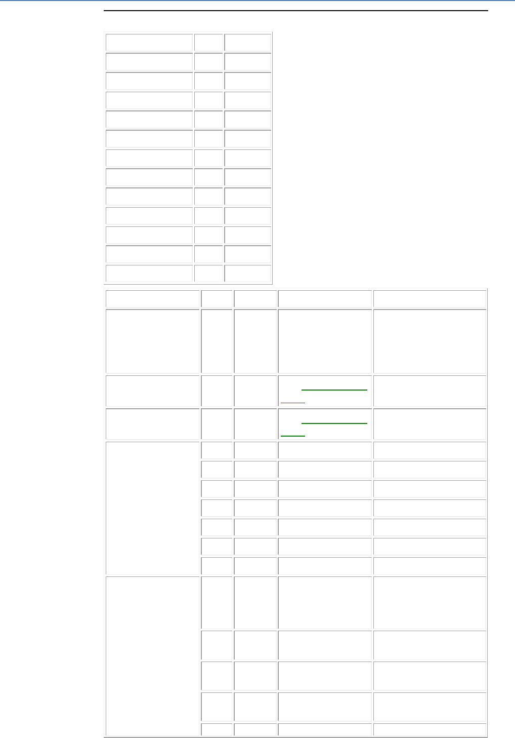
em4 soft Online Help
214
Data Exchanged
Name
R/W
Address
XWIN
R/W
0001
XWIN
R/W
0002
: :
: :
: :
XWIN
R/W
0023
XWIN
R/W
0024
XBIN
R/W
0025
XWOUT
R
0026
XWOUT
R
0027
: :
: :
: :
XWOUT
R
0048
XWOUT
R
0049
XBOUT
R
0050
MSB STATUS
R
0051
0x0000
LSB STATUS
R
0052
0x0000 : Stop
0x0001 : Run
0x0002 : Debugging
0x0040 : Front-panel
parameter setting
0x0800 : Power failure
MSB STATUS
R
0053
See warning/error
code
LSB STATUS
R
0054
See warning/error
code
CLOCK
R/W
0055
second
R/W
0056
minute
R/W
0057
hour
R/W
0058
day
R/W
0059
date
R/W
0060
month
R/W
0061
year
SUMMER/WINTER
R/W
0063
Changeover
0x0000 : not confirmed
0x0001 : Europe
0x0002 : USA
0x0003 : manual
R/W
0064
SUMMER month
0x0001 : January
0x000C : December
R/W
0065
SUMMER date
0x0001 : 1st Sunday
0x0005 : 5th Sunday
R/W
0066
WINTER month
0x0001 : January
0x000C : December
R/W
0067
WINTER date
0x0001 : 1st Sunday
em4 soft Online Help
215
0x0005 : 5th Sunday
DRIFT
R/W
0068
Drift
0x0001 : 1st Sunday
0x0005 : 5th Sunday
RUN/STOP
W
0069
0x0000 : Stop
0x0001 : Run
1.5.3 Communication Via Ethernet Extension
( § 1.5.2 )
( § 1.5.3.1 )
1.5.3.1 Overview
( § 1.5.3 )
( § 1.5.3.2 )
1.5.3.2 Acquisition of IP Addresses
( § 1.5.3.1 )
( § 1.5.3.3 )
1.5.3.3 Communication on the Ethernet Network
( § 1.5.3.2 )
( § 1.5.3.4 )
1.5.3.4 Specific Requests to the TCP Diagnostics
( § 1.5.3.3 )
( § 1.5.4 )
1.5.4 Communication Interface via the 2G Connection
( § 1.5.3.4 )
( § 1.5.4.1 )
At a Glance
Subject of this Chapter
This chapter describes the programming software functions for the 2G
communication interface.
What's in this Chapter?
This chapter contains the following topics:
Overview( § 1.5.4.1 )
Directories( § 1.5.4.2 )
Configuring the 2G Communication Interface( § 1.5.4.3 )
Sending an Email via SMS( § 1.5.4.4 )
Description of the Error Codes of the 2G Communication Interface( § 1.5.4.5 )
1.5.4.1 2G Communication: Overview
( § 1.5.4 )
( § 1.5.4.2 )
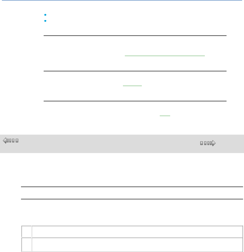
em4 soft Online Help
216
Description
"2G" communication is radio communication that is available in 2 formats:
2G SMS: the product communicates with a smartphone, a PC, an em4, using SMS.
2G e-Connect: the product communicates with a server and at the other end, a
tablet, a PC, an em4, etc. connected to the server
Configuring the Interface
Certain parameters such as the PIN code, the Access Point Name (APN), the COM
port, etc. need to be entered using the Configuring Controller Communication( § 1.5.4.3
) window.
Directory
A directory can be accessed from the Directory( § 1.5.4.2 ) menu. This directory is used
to store the various recipients with their telephone number, email, profile.
Sending an Email
The procedure for sending an email is described in this page( § 1.5.4.1 ).
1.5.4.2 Directories Menu
( §
1.5.4.1 )
( § 1.5.4.3 )
Description
The Directory menu contains programming software functions that are used to create or modify a
directory, and are necessary to use the 2G communication interface.
To create or modify the directory of recipients, proceed as follows:
Directory of Recipients
The general directory of recipients is independent of the program being edited. It is used to save
information about the recipients used regularly in the programs. To create or modify the general directory
of recipients, proceed as follows:
Ste
p
Action
1
Click on the menu : Directory / Directory.
Result: The General Directory of Recipients window appears and for each recipient shows the following:
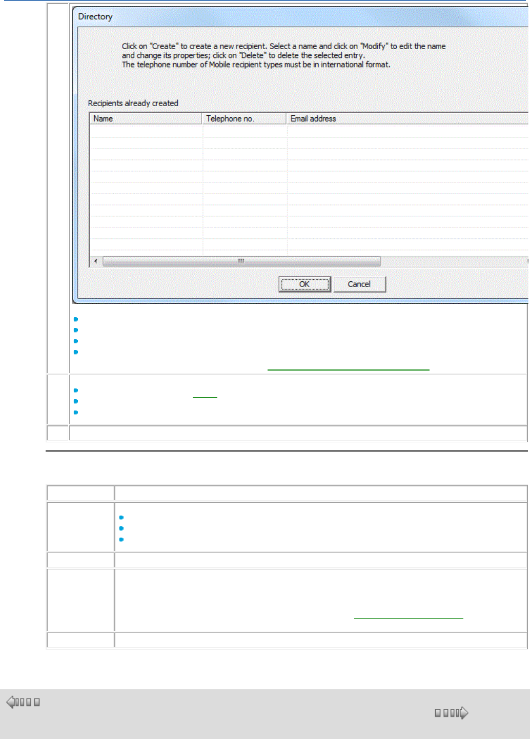
em4 soft Online Help
217
The name of the recipient,
His telephone number,
His Email address,
His Profile,
Note: : To configure the connection, click on this link: Configuring the 2G Communication Interface( § 1.5.4.3 ).
2
It is possible:
To add recipients: click on the Create( § 1.5.4.2 ) button,
To modify a recipient: select the recipient then click on the Modify button,
To delete a recipient: select the recipient then click on the Delete button,
3
Confirm by clicking on the OK button.
Creating a Recipient
When creating a new recipient, after clicking on the Create button, proceed as follows::
Step
Action
1
Select the type of recipient from among:
Administrator, 1 maximum, who has all rights without restriction,
Operator, 6 maximum, with some access restrictions,
User, 3 maximum, with read-only data access.
2
Enter recipient name (20 characters maximum).
3
Enter his telephone number or his Email.
Use the international format for mobile telephones, for example: +336********
Email: string of 64 characters maximum
Note: To send an Email via SMS, the syntax to use in the recipient Email is specific to each network operator.
Contact the modem SIM card's network operator and refer to the Composition of an SMS/Email( § 1.5.4.4 )
section for more information.
4
Confirm by clicking on the OK button.
1.5.4.3 Configuring the 2G Communication Interface
( §
1.5.4.2 )
( § 1.5.4.4 )
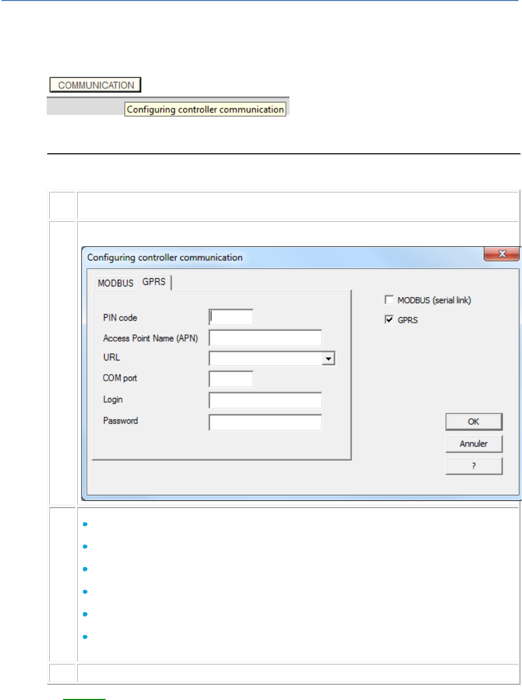
em4 soft Online Help
218
Access
With a networked base: click on the COMMUNICATION button on the edit sheet:
A Configuring Communication window appears.
Configuring Controller Communication
Procedure :
Ste
p
Action
1
Click on the GPRS tab
2
Fill in the various boxes:
PIN code :
This code is provided by the operator
Access Point Name (APN)* :
This address is provided by the operator
URL : (128 characters)
Not available in this version
COM port :
Not available in this version
Login* : (30 characters)
The Login is provided by the operator
Password* :
The Password is provided by the operator
3
Confirm changes by pressing the OK button.
- A directory( § 1.5.4.2 ) then needs to be created.
* Only to send emails
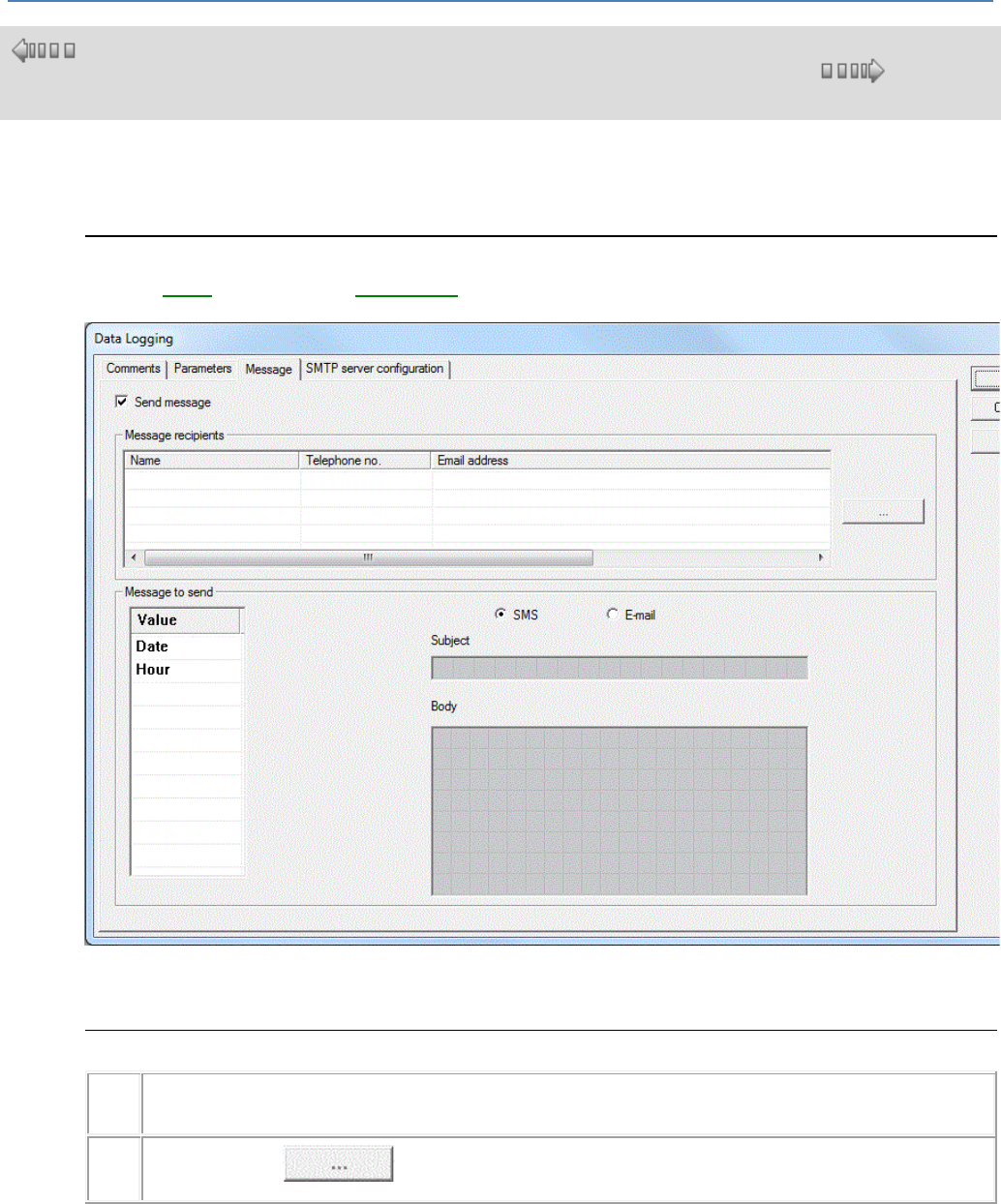
em4 soft Online Help
219
1.5.4.4 Composition of an SMS/Email
( §
1.5.4.3 )
( § 1.5.4.5 )
Description
Here we describe how to compose an SMS, or an Email.
Access
From an Event( § 1.4.2.4.7 ) or Datalogging( § 1.4.2.4.6 ) function by double-clicking on the FB and
selecting the Message tab:
Click on the Send message box to confirm the window.
Procedure:
Ste
p
Actions
1
Click on the button of the Message Recipient zone to add a recipient or modify the list of recipients of
this message.
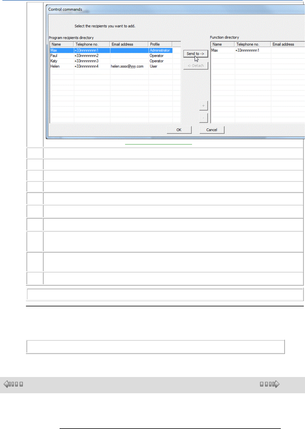
em4 soft Online Help
220
These recipients are chosen from the Directory of Program Recipients( § 1.5.4.2 ).
2
For each new recipient to be added, select it in the directory of the program and click on the Send to -> button.
3
Organize the recipients in the order of priority by using the + and - buttons.
4
For each recipient to be deleted, select it in the directory of the function and click on the <- Detach button.
5
Confirm by clicking on the OK button.
6
Choose SMS or Email
7
Click in the rectangle under the Subject part, and type your text.
8
In the central rectangle under the Body part, type your text.
9
In the Value window, click on Date, Time, Value 1, Value 2, etc.
and drag/drop the selected variable in the central rectangle under the Body part.
10
Proceed in the same way to add other values, and you are thus composing the Body of your
message.
11
Confirm changes by pressing OK.
Note: Value 1, Value 2, etc. can be formatted with decimals.
Envoi d'Email
To email sending, you must specify the URL in the SMTP server Configuration tab
The administrator must have an email adress, this is this adress that will be used as email sender.
Note: The access to some of SMTP server is protected, in this case inform the Password field.
1.5.4.5 Description of the 2G Communication Interface Error Codes
( § 1.5.4.4 )
( § 1.6 )
Description
Here we describe the errors detected by the communication interface software.
em4 soft Online Help
221
Error Codes
The majority of errors are fed back to the application, please consult the list of
errors( § 1.6.1.12 ).
In some specific cases, the application may not be informed of communication
errors.
For example:
- When the SMTP server is not compatible with the SIM card used,
- or the communication block parameters have not been set.
In these situations communication is blocked; to unblock it switch the base OFF/ON.
1.6 Functions of the Programming Workshop
( § 1.5.4.5 )
( § 1.6.1 )
At a Glance
Subject of this Section
This section describes the different functions available in the programming
workshop.
What's in this Part?
This part contains the following chapters:
Functions( § 1.6.1 )
Description of Menus( § 1.6.2 )
1.6.1 Functions
( § 1.6 )
( § 1.6.1.1 )
At a Glance
Subject of this Chapter
This chapter describes the different functions available in the programming workshop.
What's in this Chapter?
This chapter contains the following topics:
Program Configuration( § 1.6.1.1 )
Preferences of the Programming Workshop( § 1.6.1.2 )
Program Check( § 1.6.1.3 )
Write Options Window( § 1.6.1.4 )
Import an Application( § 1.6.1.5 )
Import MACRO( § 1.6.1.6 )
Conversion of Older Applications( § 1.6.1.7 )
Setting the Clock( § 1.6.1.8 )
Saving an Application( § 1.6.1.9 )
Printing the Program ( § 1.6.1.10 )
Page Header and Footer for Application Printing( § 1.6.1.11 )
Error Description( § 1.6.1.12 )
Splitting the Wiring Sheet( § 1.6.1.13 )

em4 soft Online Help
222
1.6.1.1 Program Configuration
( § 1.6.1 )
( § 1.6.1.2 )
Description
The program configuration window is used to set the different parameters linked to the
application.
The window includes at least the following four tabs:
Properties( § 1.6.1.1 )
Configuration( § 1.6.1.1 )
History( § 1.6.1.1 )
Date format( § 1.6.1.1 )
Access
The Program configuration function is accessible from the PROGRAM icon
Properties
The Properties tab is used to define the following elements:
Project name (maximum 24 characters)
Author (maximum 32 characters)
Version (0 ≤ V ≤ 255 , 0 ≤ I ≤ 255),
Comment (maximum 9 lines)
Note: When printing the comment, only line feeds introduced by the user with the
Enter key are taken into account.
Configuration
The Configuration tab is used to set the following parameters:
Adjustment of the controller basic cycle( § 1.6.1.1 ) time
WATCHDOG( § 1.6.1.1 ) action (control of the controller basic cycle time)
Frequency of all controller PWMs( § 1.4.2.2.2 ), only for controllers with PWM-type
outputs
Restricted access( § 1.6.1.1 ) to the Parameters menu of the controller front panel
Activate MACRO password protection( § 1.4.3.2.5 )
History
The History tab is used to track changes in the application.
The programmer can save the following information for each change:
Date
Programmer name
Version
Comment
Date Format
The Date format tab is used to set:
The format in which the date will be displayed, to be chosen from the following three
options:
Day/Month/Year
Month/Day/Year
Year/Month/Day

em4 soft Online Help
223
Automatic summer/winter time change.
Here you can activate or deactivate automatic time change, and choose the
changeover dates. (See How to Activate Automatic Time Change( § 1.6.1.1 ))
Basic Cycle
To be executed by the controller, this program is translated as a set of ordered
instructions, where each instruction corresponds to a function.
This set of instructions (functions) is executed periodically, therefore at regular time
intervals. This time interval is called the basic cycle time.
This time therefore corresponds to the sampling period of analog data read as inputs of
the controller and its extensions and to the refresh period of the outputs of the controller
and its extensions.
This time can be set from 6 ms to 90 ms in 2 ms steps, by default: 10 ms.
Make sure that:
Input variations that are too rapid are not masked by a cycle time that is too slow
The speed of output variation is compatible with system commands
(See also How to Debug an Application without Loading it onto the Controller:
Simulation( § 1.2.7 )
WATCHDOG
The WATCHDOG monitors the application cycle time added to the duration of processing
specific to the operation of the controller and any extensions. An overflow occurs if this
time exceeds the basic cycle time.
In the case of overflow, the different actions of the WATCHDOG are as follows:
INACTIVE: normal operating mode
ALARM: A warning state is set and the warning number corresponding to Cycle
overflow is accessible in the FAULT menu
ERROR: The program stops (OFF mode) and the error number corresponding to:
Cycle overflow is accessible in the FAULT menu.
Note: In certain communication phases, the cycle times are increased by the
communication times between the PC and the controller. No guarantee can be given
concerning the actual cycle times during this operating mode. The WATCHDOG is
always inhibited in this controller operating mode (Controller status( § 1.4.2.6.11 )).
Restricted Access
If the Restricted access option is selected then the ON/OFF menu on the front panel will
no longer be accessible after writing to the controller. Only the PARAMETERS menu
functions will be accessible.
How to Activate Automatic Time Change
To activate automatic summer/winter time change, proceed as follows:
Step
Action
1
Click on the PROGRAM button.
Result: The program configuration window appears on the screen.
2
Click on the Date Format tab.
3
Check the Activate summer/winter time change by clicking on the box.
4
Choose the dates for the time change. To do this, there are two ways to proceed:
By using the drop-down list in front of the Zone parameter, to select a geographic zone
from the three below:
Europe
USA
Other
For these three zones, the dates of time changes are preconfigured and do not require any
other adjustment.
By choosing Other in the drop-down list opposite the Zone parameter, then by manually
specifying the month and the Sunday of the two time changes.
5
Click on the OK button.
em4 soft Online Help
224
1.6.1.2 Preferences of the Programming Workshop
( § 1.6.1.1 )
( § 1.6.1.3 )
Description
The programming workshop preferences window is used to configure the general
characteristics of the workshop:
Programming workshop language: language used in the programming
workshop,
Controller language: the HMI language of the programming workshop front panel
(LCD),
Working directory: path of the directory where the applications are saved on the
PC (the access path is limited to a maximum of 128 characters, including the
program name and its extension).
Printing : To configure the headers and footers( § 1.6.1.11 ).
Access
The Preferences function can be accessed from the File menu.
1.6.1.3 Program Check
( § 1.6.1.2 )
( § 1.6.1.4 )
Overview
The Controller / Check the program menu launches program compilation. The
Compilation Results window displays the compilation result as well as a list of the
resources used and available.
Compilation is carried out automatically in the following cases:
Changeover from Edit to Simulation mode
Changeover from Edit mode to Debugging mode
Transferring the program to the controller
How to Display or Hide the Compilation Results Window
The table below shows the different display options for the Compilation Results
window.
To...
proceed as follows:
Deactivate systematic display of the
window
Check the Do not display during simulation or loading in
the controller mode box.
Display the window when the systematic
display is deactivated
Select Controller / Check the program
Activate systematic display of the window
Uncheck the Do not display during simulation or loading
in the controller mode box.
Results Window Elements
The available resources depend on the controller type. The compiler calculates the
volumes of resources used in the different memory zones of the controller.
If the values calculated are greater than the available values, they appear in red.
The table below shows the different elements that are displayed in the Compilation
Results window:
Elements
Description
Parameters zone
The parameters of the function blocks or automation functions.
Two bytes for each integer and 1 byte for the other types.
Zone for discrete data, etc.
Data in bit format.
em4 soft Online Help
225
One bit per discrete or Boolean element or per SFC step bit.
Zone for other data types
Data in byte format.
Two bytes for each integer.
Program zone
The number of bytes corresponding to all the program function blocks
and automation functions.
Estimated program duration
(ms)
Sum of all of the individual execution times for each function used.
Controller basic cycle time
(ms)
Configured cycle time. See Basic Cycle( § 1.6.1.1 ).
1.6.1.4 Write Options Window
( § 1.6.1.3 )
( § 1.6.1.5 )
Description
The Write options window appears before the application is transferred onto the
controller: menu: Controller / Write to the controller.
This window is used to:
Protect the controller program,
Save the modifications made using the software workshop before the program is
written to the controller,
Automatically launch the ON mode on the controller,
Protection
This option is used to protect the program by a password.
The user must enter the password for certain operations.
In the software workshop, the password protects access to the following functions:
Modification of the program contained in the controller,
Rereading of the program contained in the controller,
Destruction by transferring another program,
Debugging,
Comparison of the controller data with the program,
Controller diagnostics.
Save Changes
This option is used to automatically save modifications made using the software
workshop before the program is written to the controller.
Automatic Launch of ON Mode
This option can be used to automatically switch the controller to ON mode at the end
of the transfer.
1.6.1.5 Import an Application
( § 1.6.1.4 )
( § 1.6.1.6 )
Overview
The File / Import command can be used to transfer all or part of another application
into the current application.
How to Import FBD Function Blocks and FBD MACROS
FBD function blocks and/or MACROS are imported as follows.
Step
Action
em4 soft Online Help
226
1
From an FBD application, select the menu: File / Import.
2
Select the file containing the function blocks to be imported and confirm.
Note: For importing to be possible the chosen file must contain an FBD application.
3
Select the menu: Window / Tile.
Result: The current application and the imported application windows appear one below
the other.
Note: If the Import application contains MACROS, these cannot be displayed at this
stage.
4
In the Import application window, select the useful function blocks and/or MACROS.
5
Drag and drop these function blocks and/or MACROS into the current application
window.
Note: If a MACRO has been placed in the current window, it can now be opened using
the Display MACRO pop-up menu.
1.6.1.6 Importing/Exporting a MACRO
( § 1.6.1.5 )
( § 1.6.1.7 )
Overview
The File / Import MACRO command is used to import a macro.
It is also possible to export a macro( § 1.4.3.2.6 ).
1.6.1.7 Conversion of Older Applications
( § 1.6.1.6 )
( § 1.6.1.8 )
At a Glance
The programming workshop lets you open and convert applications created with
versions in .pm3 format (minimum version AC7 V2.5.0).
Procedure
The following table shows the procedure for opening an older application:
Step
Action
1
Select the Open command from the File menu.
2
Select the file made using the older application.
3
Confirm with Open.
Result: A conversion confirmation window will appear.
4
Confirm with OK.
5
Check and correct, if necessary, the imported program, especially the positions of the
inputs and outputs and the PWM frequencies.
Application-specific functions are not imported in this version.
1.6.1.8 Setting the Clock
( § 1.6.1.7 )
( § 1.6.1.9 )
Overview
The controller clock can be set by one or other of the following methods:
Using the programming workshop( § 1.5.1.9 )
em4 soft Online Help
227
via the front face of the product, Clock( § 1.3.4.1 ) menu,
1.6.1.9 Saving an Application
( § 1.6.1.8 )
( § 1.6.1.10 )
Overview
When it is saved, the user application and its configuration are stored on the PC.
Access
The save functions: Save and Save As can be accessed from the File
menu.
1.6.1.10 Printing the Program
( § 1.6.1.9 )
( § 1.6.1.11 )
At a Glance
Printing an application enables you to create full documentation for the application. It
consists of:
A wiring diagram for the application,
Wiring diagram(s) of macro(s),
The content of the supervision window,
A table with the following for each symbol:
A representation of the symbol,
Its chart number,
The associated comment,
The parameter(s) with their values and their descriptions.
Commands
The following table lists the commands available from the File menu used for printing:
Command
Description
Print
Used to print the document.
Print preview
Used to preview the print job to check for the desired result.
Print setup
Opens the print setup window.
Print Options
Different items may be printed and several options are offered from the Menu: File /
Print setup:
Cover Page: Cover page print of the program properties defined by the Menu: File
/ Properties...
Edit window: Print of the wiring diagrams with the print area options,
Macro window: Print the Macro wiring diagrams, with the same print area options
as the ones in the edit window, (this option is only available if there is at least one
macro and if the macro protection( § 1.4.3.2.5 ) allows),
Supervision window: Print the supervision window with the print area options,
Summary table : Print the function summary table.
Page Setup to define the paper, orientation, margins.
Headers and footers( § 1.6.1.11 ).
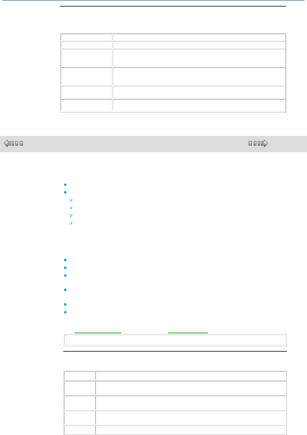
em4 soft Online Help
228
Print Area Options
The print area options for the Edit, Macro, and Supervision windows which can be
accessed from the Menu: File Print setup are described in the following table:
Option
Description
All
Prints the entire wiring sheet.
Visible part
Prints first the visible part of the screen at the time of printing according to the
current zoom factor. The non-visible part of the screen is printed on any space
left on the page.
Selection
Prints first the selected objects at the time of printing according to the current
zoom factor. Concerning the unselected objects, they are printed on any space
left on the page.
Number of sheets (1, 2
or 4 sheets)
Indicates the number of sheets that will be used to print each diagram
Includes the
background
Prints the background of the wiring sheet
1.6.1.11 Page Header and Footer for Application Printing
( § 1.6.1.10 )
( § 1.6.1.12 )
At a Glance
This function is used to insert the following into the printed application document:
A logo,
Text with:
Comments,
The name of the application file,
The page numbers and number of pages,
The time and the date (current, last modification).
The window is broken down into 2 series of 3 white boxes. The upper 3 correspond
to the header and the lower 3 to the footer.
Several text items or a logo can be inserted into each of the boxes.
The default contents of each of the six boxes are:
Upper left: The name of the project file followed by the version,
Upper-middle: Logo:
Upper-right: Project name (entered in the Property tab of the Program
Configuration window),
Lower-left: Project name (entered in the Property tab of the Program
configuration window),
Lower-middle: Date of the last project save,
Lower-right: The page number and total number of pages.
The procedures to use for customizing these default values are described further on:
see Inserting a Logo( § 1.6.1.11 ) and Inserting Text( § 1.6.1.11 ).
Note: A logo and text cannot occupy the same box.
Inserting a Logo
The following table shows the procedure for inserting a logo:
Step
Action
1
Select the Print setup command from the File menu.
Result: the Print setup window appears.
2
Press the Headers and footers button.
Result: the Select headers and footers window appears.
3
Position the mouse cursor in one of the upper or lower boxes where you would like to
place the logo.
4
Check the Logo box.
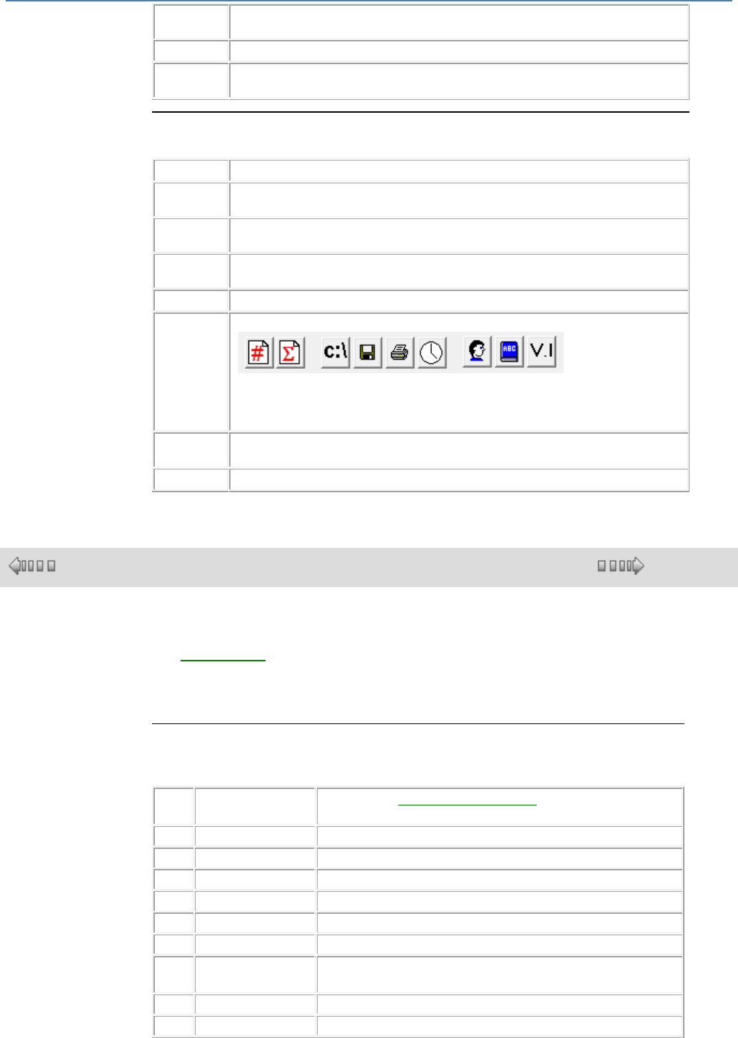
em4 soft Online Help
229
5
Press the ... button.
Result: the Open window appears.
6
Select the logo file (.bmp, .jpg, .gif).
7
Confirm with Open.
Result: the file path name appears in the selected box.
Inserting Text
The following table shows the procedure for inserting text:
Step
Action
1
Select the Print setup command from the File menu.
Result: the Print setup window appears.
2
Press the Headers and footers button.
Result: the Select headers and footers window appears.
3
Position the mouse cursor in one of the upper or lower boxes where you would like to
place the text.
4
Check the Text box.
5
Press the icon corresponding to the text that you would like to insert:
Page number, number of pages,
File name, file date, date of printing, time of printing,
Author, title, version.
Result: the inserted text appears between { }.
6
Repeat step 5 to insert another text item in the same box or resume the procedure from
step 3.
7
Confirm with OK.
1.6.1.12 Error Description
( § 1.6.1.11 )
( § 1.6.1.13 )
Description
The Default menu( § 1.3.4.2 ) of the controllers with screen is used to display
and acknowledge the errors or warnings detected by the controller software.
To acknowledge an error or warning on a controller without screen, switch it off then
on again.
Possible Errors
List of errors:
1
Base WARNING
Cycle time ( program configuration( § 1.6.1.1 ) :
Watchdog action: alarm)
2
Base WARNING
Surcharge sortie PWM ou sortie non alimentée
3
Base WARNING
Dialog problem with the accessory
4
Base WARNING
Accessory missing
5
Base WARNING
Problem with the serial Flash memory
6
Base WARNING
Clock problem (RTC)
7
Base WARNING
Problem on current inputs
500
Base fault
Fault during Firmware updating via the communication
card
501
Base fault
Fault during Firmware updating
502
Base fault
Fault during BootLoader updating

em4 soft Online Help
230
503
Base fault
Memory internal fault
504
Base fault
SPI bus fault
505
Base fault
Cycle time( § 1.6.1.1 ) (program configuration: Watchdog
action: error)
506
Base fault
Fault when numbering a block in the application
507
Base fault
Base type fault
508
Base fault
Extension 1 type fault
509
Base fault
Extension 2 type fault
510
Base fault
The serial Flash memory is damaged
511
Base fault
Fault when updating the communication card
512
Base fault
Internal WATCHDOG( § 1.6.1.1 ) fault, reset problem
1000
Extension 1
WARNING
Surcharge sortie PWM ou sortie non alimentée
1001
Extension 1
WARNING
Surcharge entrée analogique
1002
Extension 1
WARNING
Surcharge sortie analogique
1500
Extension 1 fault
No communication with extension 1
1501
Extension 1 fault
Défaut Firmware extension 1
2000
Extension 2
WARNING
Surcharge sortie PWM ou sortie non alimentée
2002
Extension 2
WARNING
Surcharge entrée analogique
2003
Extension 2
WARNING
Surcharge sortie analogique
2500
Extension 2 fault
No communication with extension 2
2501
Extension 2 fault
Défaut Firmware extension 2
3000
Com card
WARNING
Card not connected to the operator's GPRS network
3001
Com card
WARNING
GPRS not displayed but in the process of connecting
3002
Com card
WARNING
GPRS registration rejected.
3003
Com card
WARNING
The status of the GPRS network connection is unknown
3004
Com card
WARNING
The card has been disconnected by the operator
3005
Com card
WARNING
Technical problem (aerial, etc.), card not connected to
the operator's GPRS network
3006
Com card
WARNING
GSM not displayed but in the process of connecting
3007
Com card
WARNING
GSM registration rejected.
3008
Com card
WARNING
The status of the GSM network connection is unknown
3009
Com card
WARNING
SIM card: status unknown
3010
Com card
WARNING
SIM card: busy
3011
Com card
WARNING
SIM card: the card is locked by a PIN code
3012
Com card
WARNING
SIM card: locked by a different code from the PIN, e.g.:
PUK or PIN2

em4 soft Online Help
231
3013
Com card
WARNING
SIM card: there is no card in the socket
3014
Com card
WARNING
SIM card: the card is present but not responding
3015
Com card
WARNING
SIM card: the socket is inserted but the card status is
unknown
3016
Com card
WARNING
SIM card: all attempts to communicate with the card
have failed
3017
Com card
WARNING
The aerial is missing, can only be used with detectable
aerials
3018
Com card
WARNING
Temperature too high or too low
3019
Com card
WARNING
The communication card is no longer responding.
3020
Com card
WARNING
Défaut communication SMTP
3021
Com card
WARNING
Défaut envoi Mail
3022
Com card
WARNING
Défaut configuration SMS
3023
Com card
WARNING
Défaut serveur SMS
3024
Com card
WARNING
Défaut lecture SMS
3025
Com card
WARNING
Défaut envoi SMS
3026
Com card
WARNING
Défaut envoi SMS car serveur non connecté
3027
Com card
WARNING
Défaut envoi SMS car serveur occupé
3028
Com card
WARNING
Défaut envoi SMS car destinataire erroné
3030
Com card
WARNING
Initialisation de la communication avec le serveur a
échoué
3031
Com card
WARNING
Ouverture de la connexion avec le serveur a échoué
3032
Com card
WARNING
Création de la connexion avec le serveur a échoué
3033
Com card
WARNING
La connexion avec le serveur a échoué
3500
Com card fault
The Firmware content is incorrect
3501
Com card fault
The BootLoader content is incorrect
3502
Com card fault
Memory internal fault
3503
Com card fault
The communication card application has not been
verified
3504
Com card fault
Error during execution of the communication card
application
3505
Com card fault
Serial Flash memory fault
3506
Com card fault
The sender/receiver part is no longer responding
3507
Com card fault
Failure while writing the communication card µc internal
flash memory
3508
Com card fault
There is not enough memory to work correctly.
3509
Com card fault
The supply voltage is outside the acceptable range
3510
Com card fault
Temperature too high or too low, the module has
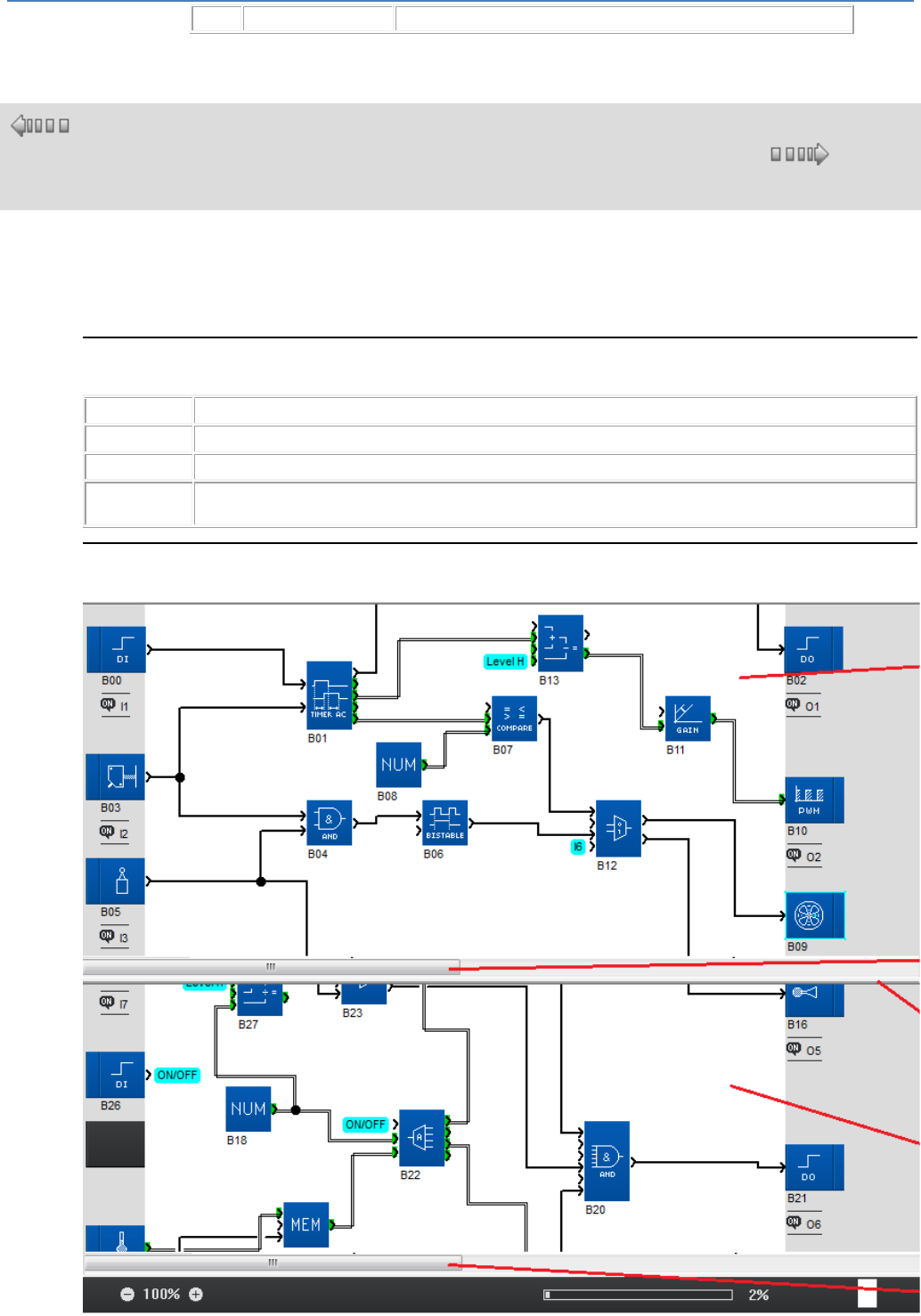
em4 soft Online Help
232
stopped to avoid damaging itself
1.6.1.13 Splitting the Wiring Sheet
( §
1.6.1.12
)
( § 1.6.2 )
Introduction
The wiring sheet can be split in 2. Splitting is used to display 2 different parts of the wiring sheet on the
same screen.
How to Split the Display
To split the display, proceed as follows:
Step
Action
1
Select the menu: Window / Split display.
2
Move the cursor to the place where you wish to split the display.
3
Click on the left mouse button.
Result: The wiring sheet will split vertically into two displays.
Structure of the Split Wiring Sheet
The split wiring sheet is structured as follows:
em4 soft Online Help
233
The elements of the split wiring sheet are described below:
Number
Element
1
Display of the upper part.
2
Vertical scroll bar for the upper part.
3
Horizontal scroll bar for the upper part.
4
Splitting bar.
5
Display of the lower part.
6
Vertical scroll bar for the lower part.
7
Horizontal scroll bar for the lower part.
Use of the Split Wiring Sheet
The split wiring sheet can be used to perform the following actions:
To...
proceed as follows:
Make the desired function blocks appear in the upper
part...
Move the scroll bars for the upper part.
Make the desired function blocks appear in the lower
part...
Move the scroll bars for the lower part.
Move the splitting bar to the desired location...
Click on it with the mouse.
Connect the function blocks of the upper and lower part...
Click on the start block output.
Join the start block input by holding down the left mouse button
and crossing the splitting bar, if necessary.
Release.
How to Cancel the Split Display
To cancel the split display select the menu: Window / Cancel split.
Result:
The lower display disappears
The upper display is displayed on the entire wiring sheet
Note: To cancel the split display, you can also click on the splitting bar and drag it down to the scroll
bar of the lower display or to the footer.
1.6.2 Description of Menus
( § 1.6.1.13 )
( § 1. )
Description
Description of the programming workshop menus
File( § 1.6.2 )
Edit( § 1.6.2 )
Mode( § 1.6.2 )
Display( § 1.6.2 )
Tools( § 1.6.2 )
Controller( § 1.6.2 )
Options( § 1.6.2 )
Directories( § 1.6.2 )
Draw( § 1.6.2 )
Window ( § 1.6.2 )
?( § 1.6.2 )
File Menu
Description of commands in the File menu:
Command
Description
New ( § 1.1.2 )
Creates a new project
em4 soft Online Help
234
Open
Opens an existing project
Close
Closes the project being edited (*)
Save( § 1.6.1.9 )
Saves the project being edited (*)
Save As( § 1.6.1.9 )
Saves the project being edited under another name (*)
Print...( § 1.6.1.10 )
Prints the project (*)
Print preview( § 1.6.1.10 )
Lets the user view the project as it will appear when printed (*)
Print setup...( § 1.6.1.10 )
Configures the print characteristics of the project (*)
Import...
Import Application( § 1.6.1.5 ) : Imports the edit window of another project
(*)
Import Macro( § 1.4.3.2.6 ) : Imports a macro
Note: Only programs, parts of programs or Macros of the same type as the
one being edited can be imported.
Properties...( § 1.6.1.1 )
The different parameters linked to the application can be set in the
Program Configuration window.(*)
Preferences...( § 1.6.1.2 )
Configures the general characteristics of the programming workshop.
No. name_file.pm3
Lists the last 4 files opened recently.
Exit
Closes the programming workshop.
Note: (*) Only available if a project file is open in the programming workshop.
Edit Menu
Description of commands in the Edit menu:
Command
Description
Cancel...
Cancels the last operation carried out (50 cancellation levels).
Redo
Redoes the action which was previously undone.
Cut
Copies and deletes the selected element (placed on the clipboard)
Copy
Copies the selected elements to the clipboard
Paste
Pastes the element from the clipboard
Clear
Clears the contents of all of the selected boxes
Select All
Selects the entire wiring sheet
Find...
Searches for a function in the program using its name or an associated
comment.
Activate display
dependencies mode( §
1.4.3.1.8 )
Activates or deactivates the mode used to display the functions depending
on a node or function.
Mode Menu
Description of commands in the Mode menu:
Command
Description
Edit( § 1.1.1 )
Used to build programs, which corresponds to development of the
application.
Simulation( § 1.1.1 )
The program is executed offline directly in the programming workshop
(simulated on the PC).
Debugging( § 1.1.1 )
The program is executed on the controller, the programming workshop is
connected to the controller.
Display Menu
Description of commands in the Display menu:
Command
Description
Function bar.
Displays or hides the function bar
Drawing bar
Displays or hides the drawing bar.
Simulation/Debugging bar
Displays or hides the simu/debugging bar.
Program view
Used to create or modify a program.
Program view in FBD mode( § 1.4.1.1 )
Settings view
Lists all the automation functions with parameters used in the
application.
Settings view in FBD mode( § 1.4.1.1 )
Comments
Used to show/hide the program comments (the comments are
displayed under the function block).
Block numbers
Displays/hides the function block numbers
em4 soft Online Help
235
Grid
Submenus:
Display the grid: Shows/hides the wiring sheet grid.
Tools Menu
Description of commands in the Tools menu (FBD-specific):
Command
Description
Align( § 1.4.3.2.4 )
Positions objects in relation to one another:
Left
Right
Top
Bottom
Center objects vertically
Center objects horizontally
Distribute
Distribute objects:
Distribute horizontally
Distribute vertically
Order( § 1.4.3.2.4 )
Positions objects in relation to one another:
Bring to front
Send to back
Group( § 1.4.3.2.2 )
Creates composite objects
Ungroup( § 1.4.3.2.2 )
Ungroups composite objects
Create a Macro( § 1.4.3.2.5 )
Groups together several FBD functions in one Macro.
Display Macro( § 1.4.3.2.5 )
Displays the details of a Macro.
Save Macro( § 1.4.3.2.5 )
Archive your macro in the Macro tab of the Function Bar.
Renumber functions
Used to reassign the numbers of consecutive blocks starting from
number B00.
Renumber links
Used to reassign numbers of consecutive links
Wiring mode( § 1.4.3.1.3 )
Used to change the type of link between the function blocks:
Text
Wiring
(This option specifies the type for all future links)
Controller Menu
Description of commands in the Controller menu:
Command
Description
Choose the type of controller...( §
1.1.2 )
Choice of controller type with its associated functions and connected
extensions.
Configure Connection...( § 1.5.1.1 )
Establish the connection parameters between the programming
workshop and the controller
Read in the controller( § 1.5.1.3 )
Transfers the application from the controller to the PC
Write to the controller( § 1.5.1.2 )
Transfers the application from the PC to the controller
Compare the data in the controller
with the program( § 1.5.1.5 )
Used to compare the data contained in the controller and the data
produced by compiling the programming workshop's application.
Clear the controller contents( §
1.5.1.8 )
Clears the program and erases all data in the controller
Controller diagnostics( § 1.5.1.6 )
The diagnostics function allows you to view the controller
characteristics.
Check program( § 1.6.1.3 )
Checks program consistency.
Start controller and Reset saved
parameters( § 1.5.1.4 )
Initializes and starts the program.
Start controller without Reset( §
1.5.1.4 )
Starts the program without initializing the current values of functions
for which the Save on power failure is activated.
Turn the controller off( § 1.5.1.4 )
Stops the program.
Read/Write date and time( §
1.5.1.9 )
Used to configure the controller clock.
List of application-specific
functions
Submenus:
In the controller ...: displays the list of application-specific
functions available in the controller.
In the application ...: used to display and modify the list of
application-specific functions that can be used in the application.
Update Controller Firmware and
Language( § 1.5.1.11 )
Downloads a new version of the firmware and/or the new language( §
1.5.1.10 ) to the controller
em4 soft Online Help
236
Remote Control of Front Panel
Used to remotely control the controller connected to the PC.
ON: starts the program
OFF: stops the program
Options Menu
Description of commands in the Options menu:
Command
Description
Date format( § 1.6.1.1 )
Sets the date format in the program configuration window.
Directories Menu
Description of commands in the Directories menu:
Command
Description
Directory( § 1.5.4.2 )
Used to configure the telephone numbers and access rights of
recipients associated with a program.
Draw Menu( § 1.4.3.1.6 )
In the edit and supervision sheet it is possible to create shapes such as lines,
rectangles, ellipses or text. You can also insert an image in BMP, JPG, GIF format. It
is possible to modify the borders and line width.
Window Menu
Description of commands in the Window menu:
Command
Description
Cascade
Organizes the windows in cascade
Tile
Tiles the windows horizontally
Arrange icons
Rearranges the windows
Split display/Cancel split( §
1.6.1.13 )
Divides the display in two parts, each displaying one part of the
wiring sheet./Cancel this split.
List of open windows
Activates the selected window, Front panel, Supervision or Edit
Help menu
Description of commands in the Help menu:
Command
Description
Help
Provides access to the online help
About the programming workshop
Displays program information, the version number and copyright
details
