Crow Electronic Engineering CRDU DECT ULE transceiver User Manual 1

Crow Electronic Engineering Ltd DECT ULE transceiver 1

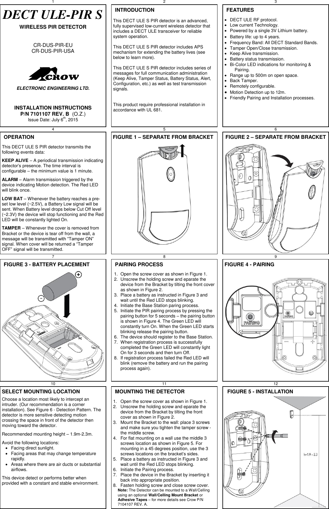
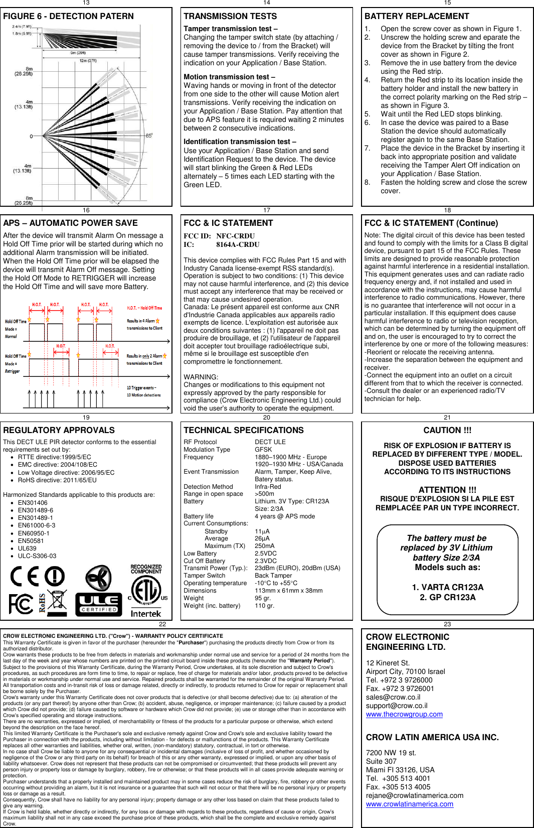
Users Manual CR-DU-PIR

  1  2   3 DECT ULE-PIR S WIRELESS PIR DETECTOR   CR-DUS-PIR-EU CR-DUS-PIR-USA    ELECTRONIC ENGINEERING LTD.   INSTALLATION INSTRUCTIONS P/N 7101107 REV. B  (O.Z.) Issue Date: July 6th, 2015  INTRODUCTION This DECT ULE S PIR detector is an advanced, fully supervised low-current wireless detector that includes a DECT ULE transceiver for reliable system operation.  This DECT ULE S PIR detector includes APS mechanism for extending the battery lives (see below to learn more).  This DECT ULE S PIR detector includes series of messages for full communication administration (Keep Alive, Tamper Status, Battery Status, Alert, Configuration, etc.) as well as test transmission signals.   This product require professional installation in accordance with UL 681.  FEATURES   DECT ULE RF protocol.   Low current Technology.   Powered by a single 3V Lithium battery.   Battery life: up to 4 years.   Frequency Band: All DECT Standard Bands.   Tamper Open/Close transmission.   Keep Alive transmission.   Battery status transmission.  Bi-Color LED indications for monitoring & Pairing.   Range up to 500m on open space.   Back Tamper.    Remotely configurable.  Motion Detection up to 12m.   Friendly Pairing and Installation processes. 4  5  6 OPERATION This DECT ULE S PIR detector transmits the following events data: KEEP ALIVE – A periodical transmission indicating detector’s presence. The time interval is configurable – the minimum value is 1 minute. ALARM – Alarm transmission triggered by the device indicating Motion detection. The Red LED will blink once. LOW BAT – Whenever the battery reaches a pre-set low level (~2.5V), a Battery Low signal will be sent. When Battery level drops below Cut Off level (~2.3V) the device will stop functioning and the Red LED will be constantly lighted On. TAMPER – Whenever the cover is removed from Bracket or the device is tear off from the wall, a message will be transmitted with “Tamper ON” signal. When cover will be returned a “Tamper OFF” signal will be transmitted.    FIGURE 1 – SEPARATE FROM BRACKET   FIGURE 2 – SEPARATE FROM BRACKET  7  8  9 FIGURE 3 - BATTERY PLACEMENT   PAIRING PROCESS 1.  Open the screw cover as shown in Figure 1. 2.  Unscrew the holding screw and eparate the device from the Bracket by tilting the front cover as shown in Figure 2. 3.  Place a battery as instructed in Figure 3 and wait until the Red LED stops blinking. 4.  Initiate the Base Station paring process. 5.  Initiate the PIR pairing process by pressing the pairing button for 5 seconds – the pairing button is shown in Figure 4. The Green LED will constantly turn On. When the Green LED starts blinking release the pairing button. 6.  The device should register to the Base Station. 7.  When registration process is successfully completed the Green LED will constantly light On for 3 seconds and then turn Off. 8.  If registration process failed the Red LED will blink (remove the battery and run the pairing process again).   FIGURE 4 - PAIRING    10  11  12 SELECT MOUNTING LOCATION Choose a location most likely to intercept an intruder. (Our recommendation is a corner installation). See Figure 6 - Detection Pattern. The detector is more sensitive detecting motion crossing the space in front of the detector then moving toward the detector. Recommended mounting height – 1.9m-2.3m. Avoid the following locations:   Facing direct sunlight.   Facing areas that may change temperature rapidly.   Areas where there are air ducts or substantial airflows. This device detect or performs better when provided with a constant and stable environment.    MOUNTING THE DETECTOR 1.  Open the screw cover as shown in Figure 1. 2.  Unscrew the holding screw and eparate the device from the Bracket by tilting the front cover as shown in Figure 2. 3.  Mount the Bracket to the wall: place 3 screws and make sure you tighten the tamper screw - the middle screw. 4.  For flat mounting on a wall use the middle 3 screws location as shown in Figure 5. For mounting in a 45 degrees position, use the 3 screws locations on the bracket’s sides. 5.  Place a battery as instructed in Figure 3 and wait until the Red LED stops blinking. 6.  Initiate the Pairing process.  7.  Place the device in the Bracket by inserting it back into appropriate position.  8.  Fasten holding screw and close screw cover. Note: The Detector can be mounted to a Wall/Celling using an optional Wall/Celling Mount Bracket or Adhesive Tapes – for more details see Crow P/N 7104107 REV. A.  FIGURE 5 - INSTALLATION
  13  14   15 FIGURE 6 - DETECTION PATERN   TRANSMISSION TESTS Tamper transmission test – Changing the tamper switch state (by attaching / removing the device to / from the Bracket) will cause tamper transmissions. Verify receiving the indication on your Application / Base Station. Motion transmission test – Waving hands or moving in front of the detector from one side to the other will cause Motion alert transmissions. Verify receiving the indication on your Application / Base Station. Pay attention that due to APS feature it is required waiting 2 minutes between 2 consecutive indications. Identification transmission test – Use your Application / Base Station and send Identification Request to the device. The device will start blinking the Green & Red LEDs alternately – 5 times each LED starting with the Green LED.    BATTERY REPLACEMENT 1.  Open the screw cover as shown in Figure 1. 2.  Unscrew the holding screw and eparate the device from the Bracket by tilting the front cover as shown in Figure 2.  3.  Remove the in use battery from the device using the Red strip. 4.  Return the Red strip to its location inside the battery holder and install the new battery in the correct polarity marking on the Red strip – as shown in Figure 3. 5.  Wait until the Red LED stops blinking. 6.  In case the device was paired to a Base Station the device should automatically register again to the same Base Station.  7.  Place the device in the Bracket by inserting it back into appropriate position and validate receiving the Tamper Alert Off indication on your Application / Base Station. 8.  Fasten the holding screw and close the screw cover.  16  17  18 APS – AUTOMATIC POWER SAVE After the device will transmit Alarm On message a Hold Off Time prior will be started during which no additional Alarm transmission will be initiated. When the Hold Off Time prior will be elapsed the device will transmit Alarm Off message. Setting the Hold Off Mode to RETRIGGER will increase the Hold Off Time and will save more Battery.    FCC & IC STATEMENT FCC ID:   NFC-CRDU IC:  8164A-CRDU  This device complies with FCC Rules Part 15 and with Industry Canada license-exempt RSS standard(s). Operation is subject to two conditions: (1) This device may not cause harmful interference, and (2) this device must accept any interference that may be received or that may cause undesired operation. Canada: Le présent appareil est conforme aux CNR d'Industrie Canada applicables aux appareils radio exempts de licence. L'exploitation est autorisée aux deux conditions suivantes : (1) l'appareil ne doit pas produire de brouillage, et (2) l'utilisateur de l'appareil doit accepter tout brouillage radioélectrique subi, même si le brouillage est susceptible d'en compromettre le fonctionnement.  WARNING: Changes or modifications to this equipment not expressly approved by the party responsible for compliance (Crow Electronic Engineering Ltd.) could void the user’s authority to operate the equipment.  FCC & IC STATEMENT (Continue) Note: The digital circuit of this device has been tested and found to comply with the limits for a Class B digital device, pursuant to part 15 of the FCC Rules. These limits are designed to provide reasonable protection against harmful interference in a residential installation. This equipment generates uses and can radiate radio frequency energy and, if not installed and used in accordance with the instructions, may cause harmful interference to radio communications. However, there is no guarantee that interference will not occur in a particular installation. If this equipment does cause harmful interference to radio or television reception, which can be determined by turning the equipment off and on, the user is encouraged to try to correct the interference by one or more of the following measures: -Reorient or relocate the receiving antenna. -Increase the separation between the equipment and receiver. -Connect the equipment into an outlet on a circuit different from that to which the receiver is connected. -Consult the dealer or an experienced radio/TV technician for help. 19  20  21 REGULATORY APPROVALS This DECT ULE PIR detector conforms to the essential requirements set out by:   RTTE directive:1999/5/EC   EMC directive: 2004/108/EC   Low Voltage directive: 2006/95/EC    RoHS directive: 2011/65/EU  Harmonized Standards applicable to this products are:   EN301406   EN301489-6   EN301489-1   EN61000-6-3   EN60950-1   EN50581    UL639    ULC-S306-03  TECHNICAL SPECIFICATIONS RF Protocol  DECT ULE Modulation Type  GFSK Frequency  1880–1900 MHz - Europe  1920–1930 MHz - USA/Canada Event Transmission  Alarm, Tamper, Keep Alive, Batery status. Detection Method  Infra-Red Range in open space  >500m Battery    Lithium. 3V Type: CR123A       Size: 2/3A Battery life  4 years @ APS mode Current Consumptions:             Standby  11A             Average  26µA             Maximum (TX)  250mA Low Battery  2.5VDC Cut Off Battery  2.3VDC Transmit Power (Typ.):    23dBm (EURO), 20dBm (USA) Tamper Switch  Back Tamper  Operating temperature   -10C to +55C   Dimensions  113mm x 61mm x 38mm Weight  95 gr.  Weight (inc. battery)  110 gr.        CAUTION !!! RISK OF EXPLOSION IF BATTERY IS REPLACED BY DIFFERENT TYPE / MODEL. DISPOSE USED BATTERIES ACCORDING TO ITS INSTRUCTIONS  ATTENTION !!!  RISQUE D'EXPLOSION SI LA PILE EST REMPLACÉE PAR UN TYPE INCORRECT.   22    23 CROW ELECTRONIC ENGINEERING LTD. ("Crow") - WARRANTY POLICY CERTIFICATE This Warranty Certificate is given in favor of the purchaser (hereunder the "Purchaser") purchasing the products directly from Crow or from its authorized distributor. Crow warrants these products to be free from defects in materials and workmanship under normal use and service for a period of 24 months from the last day of the week and year whose numbers are printed on the printed circuit board inside these products (hereunder the "Warranty Period"). Subject to the provisions of this Warranty Certificate, during the Warranty Period, Crow undertakes, at its sole discretion and subject to Crow's procedures, as such procedures are form time to time, to repair or replace, free of charge for materials and/or labor, products proved to be defective in materials or workmanship under normal use and service. Repaired products shall be warranted for the remainder of the original Warranty Period. All transportation costs and in-transit risk of loss or damage related, directly or indirectly, to products returned to Crow for repair or replacement shall be borne solely by the Purchaser.  Crow's warranty under this Warranty Certificate does not cover products that is defective (or shall become defective) due to: (a) alteration of the products (or any part thereof) by anyone other than Crow; (b) accident, abuse, negligence, or improper maintenance; (c) failure caused by a product which Crow did not provide; (d) failure caused by software or hardware which Crow did not provide; (e) use or storage other than in accordance with Crow’s specified operating and storage instructions. There are no warranties, expressed or implied, of merchantability or fitness of the products for a particular purpose or otherwise, which extend beyond the description on the face hereof.  This limited Warranty Certificate is the Purchaser's sole and exclusive remedy against Crow and Crow's sole and exclusive liability toward the Purchaser in connection with the products, including without limitation - for defects or malfunctions of the products. This Warranty Certificate replaces all other warranties and liabilities, whether oral, written, (non-mandatory) statutory, contractual, in tort or otherwise. In no case shall Crow be liable to anyone for any consequential or incidental damages (inclusive of loss of profit, and whether occasioned by negligence of the Crow or any third party on its behalf) for breach of this or any other warranty, expressed or implied, or upon any other basis of liability whatsoever. Crow does not represent that these products can not be compromised or circumvented; that these products will prevent any person injury or property loss or damage by burglary, robbery, fire or otherwise; or that these products will in all cases provide adequate warning or protection.  Purchaser understands that a properly installed and maintained product may in some cases reduce the risk of burglary, fire, robbery or other events occurring without providing an alarm, but it is not insurance or a guarantee that such will not occur or that there will be no personal injury or property loss or damage as a result.  Consequently, Crow shall have no liability for any personal injury; property damage or any other loss based on claim that these products failed to give any warning.  If Crow is held liable, whether directly or indirectly, for any loss or damage with regards to these products, regardless of cause or origin, Crow’s maximum liability shall not in any case exceed the purchase price of these products, which shall be the complete and exclusive remedy against Crow.   CROW ELECTRONIC ENGINEERING LTD.  12 Kineret St.  Airport City, 70100 Israel Tel. +972 3 9726000  Fax. +972 3 9726001 sales@crow.co.il support@crow.co.il www.thecrowgroup.com  CROW LATIN AMERICA USA INC. 7200 NW 19 st.  Suite 307 Miami FI 33126, USA Tel.  +305 513 4001 Fax. +305 513 4005 rejane@crowlatinamerica.com www.crowlatinamerica.com                The battery must be replaced by 3V Lithium battery Size 2/3A Models such as:  1. VARTA CR123A 2. GP CR123A

Navigation menu