Crow Electronic Engineering CRDU DECT ULE transceiver User Manual 1
Crow Electronic Engineering Ltd DECT ULE transceiver 1
Contents
- 1. Users Manual CR-DU-PIR
- 2. Users Manual CR-DU-MAG
- 3. Users Manual CR-DU-FLD
- 4. Users Manual CR-DU-TMP
- 5. Vtech VC7003
Users Manual CR-DU-TMP
1
2
3
DECT ULE-TMP
TEMPERATURE DETECTOR
CR-DU-TMP EURO
CR-DU-TMP USA
ELECTRONIC ENGINEERING LTD.
INSTALLATION INSTRUCTIONS
P/N 7105195REV. B (O.Z.)
Issue Date: July 6th, 2015
INTRODUCTION
This DECT ULE TMP detector is an advanced, fully
supervised low-current wireless detector that
includes a DECT ULE transceiver for reliable
system operation.
A dedicated cable is supplied with this device.
This DECT ULE TMP uses smart message control,
which verifies that all messages are successfully
transmitted, so that no event will be uninformed to
the system.
This DECT ULE TMP detector includes series of
messages for full communication administration
(Keep Alive, Tamper Status, Battery Status, Alert,
Configuration, etc.) as well as test transmission
signals.
FEATURES
DECT ULE RF protocol.
Low current Technology.
Powered by a single 3V Lithium battery.
Battery life: up to 4 years.
Frequency Band: All DECT Standard Bands.
Tamper Open/Close transmission.
Temperature reporting transmissions.
Keep Alive transmission.
Battery status transmission.
Bi-Color LED indications for monitoring &
Pairing.
Range up to 500m on open space.
Back tamper.
2 sensors – Internal & External (optional).
Remotely configurable.
Friendly Pairing and Installation processes.
4
5
6
OPERATION
The DECT ULE TMP detector transmits the
following events data:
KEEP ALIVE – A periodical transmission
indicating detector’s presence. The time interval is
configurable – the minimum value is 3 seconds.
ALARM – Indicating that measured Temperature
is out of defined Low / High thresholds. The Red
LED will blink once.
Temperature Monitoring – A periodic
transmission (configurable) indicating the
measured Internal or External temperature.
LOW BAT – A transmission indicating the battery
reached a pre-set low level (~2.5V). When Battery
level drops below Cut Off level (~2.3V) the device
will stop functioning and the Red LED will
constantly light On.
TAMPER – Whenever the cover is removed from
Bracket or the device is tear off from the wall, a
message will be transmitted with “Tamper ON”
signal. When cover will be returned a “Tamper
OFF” signal will be transmitted.
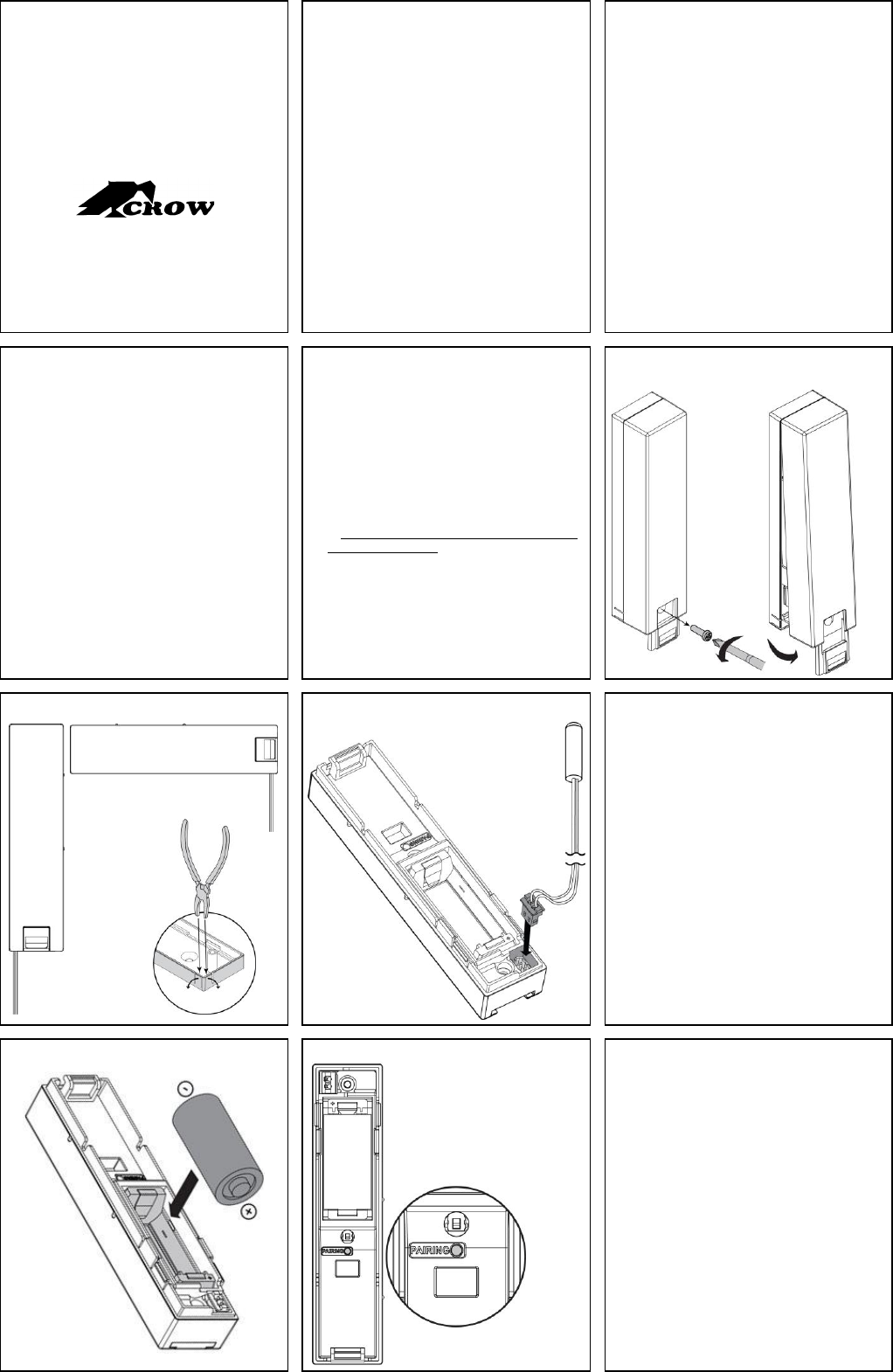
PREPARE THE DEVICE FOR
INSTALLATION
1. Open the screw cover and unscrew the holding
screw as shown in Figure 1.
2. Separate the device from the Bracket by tilting
the front cover as shown in Figure 1.
3. Break one piece of the Bracket corners
according to the device installation orientation
(Horizontal/Vertical) as shown in Figure 2.
4. Genteelly connect the External Temperature
sensor cable to its location as shown in Figure
4. Be aware that the connector can be inserted
in only one direction.
5. Continue with the pairing process.
FIGURE 1 – SEPARATE FROM BRACKET
7
8
9
FIGURE 2 – DEVICE ORIENTATION
FIGURE 3 – INSTALL THE CABLE
PAIRING PROCESS
1. Place a battery as instructed in Figure 4 and wait
until the Red LED stops blinking.
2. Initiate the Base Station pairing process.
3. Initiate the device pairing process by pressing the
pairing button for 5 seconds – the pairing button
is shown in Figure 5. The Green LED will
constantly turn On. When the Green LED starts
blinking release the pairing button.
4. The device should register to the Base Station.
5. When registration process is successfully
completed the Green LED will constantly light On
for 3 seconds and then turn off.
6. If registration process failed the Red LED will
blink (remove the battery and run the pairing
process again).
10
11
12
FIGURE 4 – BATTERY INSERTION
FIGURE 5 – PAIRING BUTTON
SELECT MOUNTING LOCATION
It is recommended to mount the device vertically on
a flat area to get maximum range.
As the detector is a wireless transceiver, and in
order to take full advantage of its sophisticated
operation, do not install the detector in areas where
large metal objects could interfere with the
transmission of signals.
TRANSMISSION TESTS
Tamper transmission test –
Changing the tamper switch state (by attaching /
removing the device to / from the Bracket) will
cause tamper transmissions. Verify receiving the
indication on your Application / Base Station.
Identification transmission test –
Use your Application / Base Station and send
Identification Request to the device. The device
will start blinking the Green & Red LEDs
alternately – 5 times each LED starting with the
Green LED.
Horizontal
Installation
Vertical
Installation
13
14
15
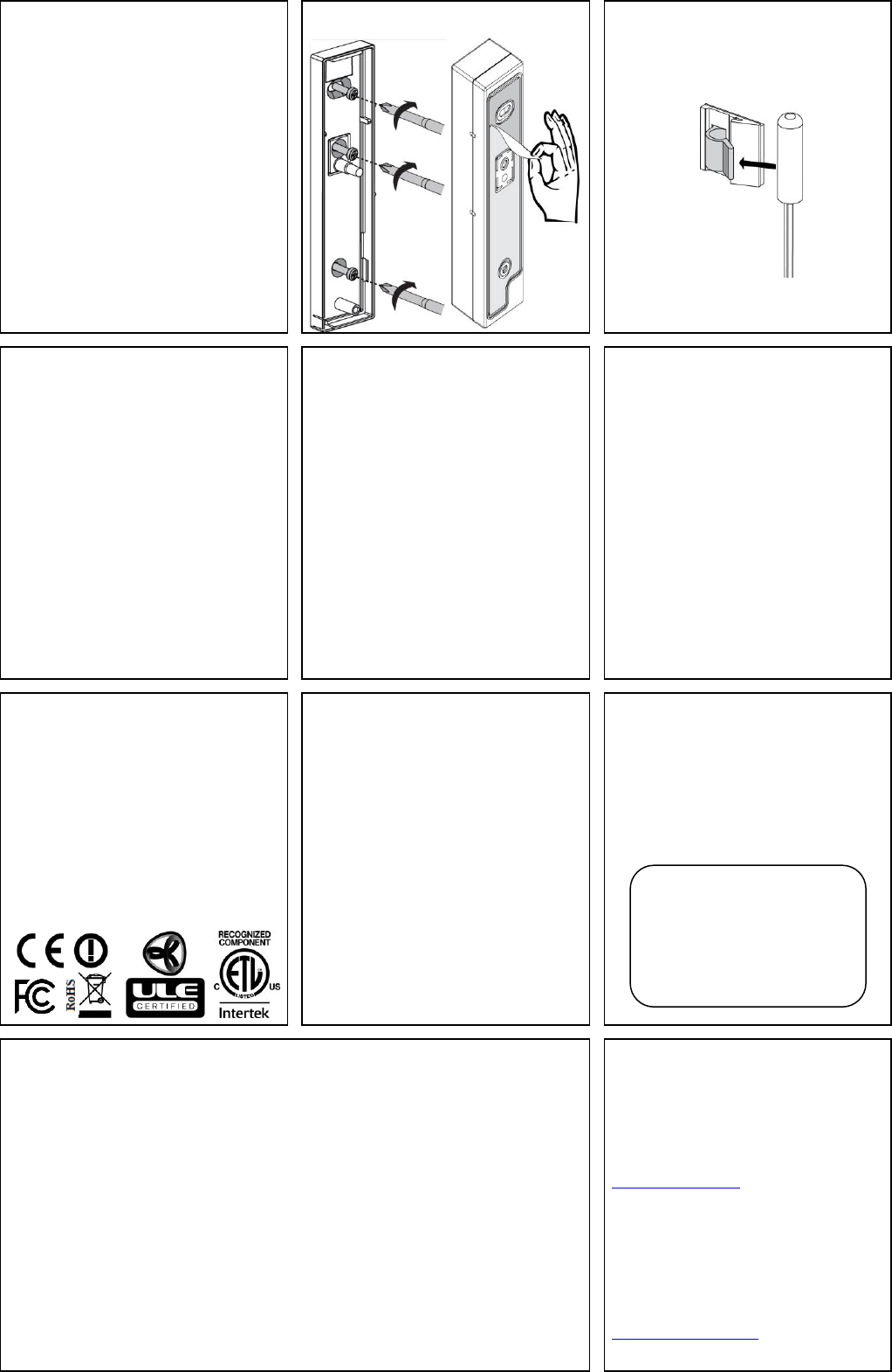
MOUNTING THE DETECTOR
1. Separate the device from its bracket by
unscrewing the holding screw and tilting the
front cover as shown in Figure 1.
2. Mount the Bracket to the surface by using the
adhesive tape strip or by using the 3 screws as
shown in Figure 6. If using the screws, make
sure to tighten the tamper screw - the middle
screw.
3. Perform the Pairing process as described
above in this document.
4. Place the device in the Bracket by inserting it
back into its appropriate position and validate
receiving the Tamper Alert Off indication on
your Application / Base Station.
5. Fasten the holding screw and close the screw
cover.
6. Mount the External sensor snap in its location
by removing the paper from the adhesive tape
and glue the snap to its location.
7. Insert the External sensor into the snap as
shown in Figure 7.
FIGURE 6 – MOUNTING THE DEVIC
FIGURE 7 – MOUNTING THE SENSOR
16
17
18
BATTERY REPLACEMENT
1. Open the screw cover and unscrew the holding
screw as shown in Figure 1.
2. Separate the device from the Bracket by tilting
the front cover as shown in Figure 1.
3. Remove the in used battery from the device.
4. Install the new battery in the correct polarity
marking – as seen in Figure 4.
5. Wait until the Red LED stops blinking.
6. In case the device was paired to a Base Station
the device should automatically register again
to the same Base Station and the Green LED
shall constantly light On for 3 seconds.
7. Create Tamper transmission, and validate
receiving it on your Application / Base Station.
8. Place the device in the Bracket by inserting it
back into appropriate position.
9. Fasten the holding screw and close the screw
cover.
FCC & IC STATEMENT
FCC ID: NFC-CRDU
IC: 8164A-CRDU
This device complies with FCC Rules Part 15 and with
Industry Canada license-exempt RSS standard(s).
Operation is subject to two conditions: (1) This device
may not cause harmful interference, and (2) this device
must accept any interference that may be received or
that may cause undesired operation.
Canada: Le présent appareil est conforme aux CNR
d'Industrie Canada applicables aux appareils radio
exempts de licence. L'exploitation est autorisée aux
deux conditions suivantes : (1) l'appareil ne doit pas
produire de brouillage, et (2) l'utilisateur de l'appareil
doit accepter tout brouillage radioélectrique subi,
même si le brouillage est susceptible d'en
compromettre le fonctionnement.
WARNING:
Changes or modifications to this equipment not
expressly approved by the party responsible for
compliance (Crow Electronic Engineering Ltd.) could
void the user’s authority to operate the equipment.
FCC & IC STATEMENT (Continue)
Note: The digital circuit of this device has been tested
and found to comply with the limits for a Class B digital
device, pursuant to part 15 of the FCC Rules. These
limits are designed to provide reasonable protection
against harmful interference in a residential installation.
This equipment generates uses and can radiate radio
frequency energy and, if not installed and used in
accordance with the instructions, may cause harmful
interference to radio communications. However, there
is no guarantee that interference will not occur in a
particular installation. If this equipment does cause
harmful interference to radio or television reception,
which can be determined by turning the equipment off
and on, the user is encouraged to try to correct the
interference by one or more of the following measures:
-Reorient or relocate the receiving antenna.
-Increase the separation between the equipment and
receiver.
-Connect the equipment into an outlet on a circuit
different from that to which the receiver is connected.
-Consult the dealer or an experienced radio/TV
technician for help.
19
20
21
REGULATORY APPROVALS
This DECT ULE detector conforms to the essential
requirements set out by:
RTTE directive:1999/5/EC
EMC directive: 2004/108/EC
Low Voltage directive: 2006/95/EC
RoHS directive: 2011/65/EU
Harmonized Standards applicable to this products are:
EN301406
EN301489-6
EN301489-1
EN61000-6-3
EN60950-1
EN50581
UL 2017
C22.2 No.205-12
TECHNICAL SPECIFICATIONS
RF Protocol DECT ULE
Modulation Type GFSK
Signaling Type Non – Emergency signaling
Type (NM)
Frequency 1880–1900 MHz - Europe
1920–1930 MHz - USA/Canada
Event Transmission Temperature, Tamper, Keep
Alive, Battery status.
Detection Method Internal & External sensors.
Range in open space >500m
Battery Lithium. 3V Type: CR123A
Size: 2/3A
Battery life expectancy >4 years (10 activation per day)
Current Consumptions: Standby 4A
Average 19µA
Maximum (TX) 250mA
Low Battery 2.5VDC
Cut Off Battery 2.3VDC
Transmit Power (Typ.): 23dBm (EURO), 20dBm (USA)
Tamper Switch Back Tamper
Operating temperature -10C to +55C
Dimensions 104mm x 24mm x 22mm
Weight 50 gr. (inc. battery 65 gr.)
Maximum Cable Length 1m
CAUTION !!!
RISK OF EXPLOSION IF BATTERY IS
REPLACED BY DIFFERENT TYPE / MODEL.
DISPOSE USED BATTERIES
ACCORDING TO ITS INSTRUCTIONS
ATTENTION !!!
RISQUE D'EXPLOSION SI LA PILE EST
REMPLACÉE PAR UN TYPE INCORRECT.
22
23
CROW ELECTRONIC ENGINEERING LTD. ("Crow") - WARRANTY POLICY CERTIFICATE
This Warranty Certificate is given in favor of the purchaser (hereunder the "Purchaser") purchasing the products directly from Crow or from its
authorized distributor.
Crow warrants these products to be free from defects in materials and workmanship under normal use and service for a period of 24 months from the
last day of the week and year whose numbers are printed on the printed circuit board inside these products (hereunder the "Warranty Period").
Subject to the provisions of this Warranty Certificate, during the Warranty Period, Crow undertakes, at its sole discretion and subject to Crow's
procedures, as such procedures are form time to time, to repair or replace, free of charge for materials and/or labor, products proved to be defective
in materials or workmanship under normal use and service. Repaired products shall be warranted for the remainder of the original Warranty Period.
All transportation costs and in-transit risk of loss or damage related, directly or indirectly, to products returned to Crow for repair or replacement shall
be borne solely by the Purchaser.
Crow's warranty under this Warranty Certificate does not cover products that is defective (or shall become defective) due to: (a) alteration of the
products (or any part thereof) by anyone other than Crow; (b) accident, abuse, negligence, or improper maintenance; (c) failure caused by a product
which Crow did not provide; (d) failure caused by software or hardware which Crow did not provide; (e) use or storage other than in accordance with
Crow’s specified operating and storage instructions.
There are no warranties, expressed or implied, of merchantability or fitness of the products for a particular purpose or otherwise, which extend
beyond the description on the face hereof.
This limited Warranty Certificate is the Purchaser's sole and exclusive remedy against Crow and Crow's sole and exclusive liability toward the
Purchaser in connection with the products, including without limitation - for defects or malfunctions of the products. This Warranty Certificate
replaces all other warranties and liabilities, whether oral, written, (non-mandatory) statutory, contractual, in tort or otherwise.
In no case shall Crow be liable to anyone for any consequential or incidental damages (inclusive of loss of profit, and whether occasioned by
negligence of the Crow or any third party on its behalf) for breach of this or any other warranty, expressed or implied, or upon any other basis of
liability whatsoever. Crow does not represent that these products can not be compromised or circumvented; that these products will prevent any
person injury or property loss or damage by burglary, robbery, fire or otherwise; or that these products will in all cases provide adequate warning or
protection.
Purchaser understands that a properly installed and maintained product may in some cases reduce the risk of burglary, fire, robbery or other events
occurring without providing an alarm, but it is not insurance or a guarantee that such will not occur or that there will be no personal injury or property
loss or damage as a result.
Consequently, Crow shall have no liability for any personal injury; property damage or any other loss based on claim that these products failed to
give any warning.
If Crow is held liable, whether directly or indirectly, for any loss or damage with regards to these products, regardless of cause or origin, Crow’s
maximum liability shall not in any case exceed the purchase price of these products, which shall be the complete and exclusive remedy against
Crow.
CROW ELECTRONIC
ENGINEERING LTD.
12 Kineret St.
Airport City, 70100 Israel
Tel. +972 3 9726000
Fax. +972 3 9726001
sales@crow.co.il
support@crow.co.il
www.thecrowgroup.com
CROW LATIN AMERICA USA INC.
7200 NW 19 st.
Suite 307
Miami FI 33126, USA
Tel. +305 513 4001
Fax. +305 513 4005
rejane@crowlatinamerica.com
www.crowlatinamerica.com
The battery must be
replaced by 3V Lithium
battery Size 2/3A
Models such as:
1. VARTA CR123A
2. GP CR123A
The battery must be replaced
by Size 2/3AA - CR123A
Lithium battery 3V
Models as: DL123A DURACELL Inc
CR123A SANYO Elc
CR123A GP
The battery must be replaced
by Size 2/3AA - CR123A
Lithium battery 3V
Models as: DL123A DURACELL Inc
CR123A SANYO Elc
CR123A GP
The battery must be replaced
by Size 2/3AA - CR123A
Lithium battery 3V
Models as: DL123A DURACELL Inc
CR123A SANYO Elc
CR123A GP
The battery must be replaced
by Size 2/3AA - CR123A
Lithium battery 3V
Models as: DL123A DURACELL Inc
CR123A SANYO Elc
CR123A GP
The battery must be replaced
by Size 2/3AA - CR123A
Lithium battery 3V
Models as: DL123A DURACELL Inc
CR123A SANYO Elc
CR123A GP