Crown Boiler 24 03 Users Manual Series IOM 12 15 05
24-09 to the manual b1257ca5-ee96-4e37-8dd3-b04a8ea64961
2015-02-05
: Crown-Boiler Crown-Boiler-24-03-Users-Manual-530079 crown-boiler-24-03-users-manual-530079 crown-boiler pdf
Open the PDF directly: View PDF ![]() .
.
Page Count: 90
1
D E S I G N E D T O LE A D
Series 24
Forced Draft Steam or Water Boilers
INSTALLATION INSTRUCTIONS
These instructions must be affixed on or adjacent to the boiler.
WARNING: Improper installation, adjustment, alteration,
service or maintenance can cause property damage, injury,
or loss of life. For assistance or additional information, con-
sult a qualified installer, service agency or the gas supplier.
This boiler requires a special venting system. Read these
instructions carefully before installing.
Models:
• 24-03
• 24-04
• 24-05
• 24-06
• 24-07
• 24-08
• 24-09
• 24-10
• 24-11
• 24-12
Manufacturer of Hydronic Heating Products
P.O. Box 14818 3633 I. Street
Philadelphia, PA 19134
Tel: (215) 535-8900 • Fax: (215) 535-9736 • www.crownboiler.com
D E S I G N E D T O LE A D

2
3
IMPORTANT INFORMATION - READ CAREFULLY
,gnibmulPlacoLdnaetatS,lanoitaNhtiwecnadroccanidellatsniebtsumsreliobllA
esehT.seitilitugnivresehtfosnoitalugerehtdnasedoClacirtcelEdnagnitaeH
gnivahseitirohtuA.launamnoitcurtsnisihtmorfreffidyamsnoitalugeRdnasedoC
.edamerasnoitallatsnierofebdetlusnocebdluohsnoitcidsiruj
:sdradnatSgniwollofehtotedamebdluohsecnerefer,sesacllanI
.A
.B
.C
.D
.E
liOfonoitallatsnI“,13APFN/ISNAdradnatSlanoitaNnaciremAfonoitidEtnerruC
.secitcarpnoitallatsnidednemmocerrof,”tnempiuqEgninruB
.1.322ZISNA/45APFN,edoCsaGleuFlanoitaNfonoitidEtnerruC
,syenmihC“,112APFN/ISNAdradnatSlanoitaNnaciremAfonoitidEtnerruC
.stnemeriuqergnitneVroF,”secnailppAgninruBleuFdiloSdna,stneV,secalperiF
,1-DSCEMSAsreenignElacinahceMfoyteicoSnaciremAfonoitidEtnerruC
dnaylbmessarof,"srelioBderiFyllacitamotuArofseciveDytefaSdnaslortnoC"
.secivedytefasdnaslortnocfosnoitarepo
lacirtcelElanoitaNehthtiwecnadroccaniedamebllahssreliobnogniriwllA
.snoitalugeRlacoLro/dnaedoC
DANGER
Indicates an imminently hazardous situation
which, if not avoided, will result in death,
serious injury or substantial property
damage.
CAUTION
Indicates a potentially hazardous situation
which, if not avoided, may result in moderate
or minor injury or property damage.
WARNING
Indicates a potentially hazardous situation
which, if not avoided, could result in death,
serious injury or substantial property
damage.
NOTICE
Indicates special instructions on installation,
operation, or maintenance which are
important but not related to personal injury
hazards.

4
WARNING
Improper installation, adjustment, alteration, service or maintenance can cause property
damage, personal injury or loss of life. Failure to follow all instructions in the proper order
can cause personal injury or death. Read and understand all instructions, including all
those contained in component manufacturers manuals which are provided with the
appliance before installing, starting-up, operating, maintaining or servicing this appliance.
Keep this manual and literature in legible condition and posted near appliance for reference
by owner and service technician.
This boiler requires regular maintenance and service to operate safely. Follow the
instructions contained in this manual. Installation, maintenance, and service must be
performed only by an experienced, skilled and knowledgeable installer or service agency.
All heating systems should be designed by competent contractors and only persons
knowledgeable in the layout and installation of hydronic heating systems should attempt
installation of any boiler. It is the responsibility of the installing contractor to see that all
controls are correctly installed and are operating properly when the installation is
completed. Installation is not complete unless a pressure relief valve is installed into the
specified tapping located at the rear of appliance - See Section III of this manual for details.
This boiler is suitable for installation on combustible flooring. Do not install boiler on
carpeting. Do not operate on floors where heat affected material is below.
Do not tamper with or alter the boiler or controls. Retain your contractor or a competent
serviceman to assure that the unit is properly adjusted and maintained.
Clean boiler at least once a year - preferably at the start of the heating season to remove
soot and scale. The inside of combustion chamber should also be cleaned and inspected
at the same time.
Have Burner and Controls checked at least once a year or as may be necessitated.
Do not operate unit with jumpered or absent controls or safety devices.
Do not operate unit if any control, switch, component, or device has been subject to water.
Return water cannot be lower than 135°F for prolonged periods of time. Operation under
these conditions will result in sustained condensing within the combustion chamber and
potentially reduce boiler longevity.
In addition, the return water cannot be introduced into the boiler if it is more than 40°F less
than the idle boiler temperature. Continued operation under these conditions may result in
premature boiler failure through thermal shock.
Example
: A boiler that has been idle for some time since the last heat demand cycle may
have it's boiler water temperature reduced to 150°F. The return temperature from the next
zone activation cannot be less than 110°F.
If the above conditions exist, an RTC system must be installed to protect the boiler from
sustained condensing operation and thermal shock.
DANGER
DO NOT store or use gasoline or other flammable vapors or liquids in the vicinity of this or any
other appliance.

5
GNINRAW
,animulaniatnocleufehtdnanoitsubmocfostcudorp,noitcurtsnocfoslairetamecnailppA
rocixotrehtoro/dnasedyhedla,sedixonegortin,edixonomnobrac,slatemyvaeh,acilis
ehtotnwonkerahcihwdnayrujnisuoiresrohtaedesuacnachcihwsecnatsbuslufmrah
esusyawlA.mrahevitcudorperrehtodnastcefedhtrib,recnacesuacotainrofilaCfoetats
ehtybraengnikrowrognicivresnehwtnempiuqednasrotaripser,gnihtolcytefasreporp
.ecnailppa
ynawercsnutonoD.serusserphgihrednumaetsroretawtohyrevsniatnocreliobsihT
ylevitisoptuohtiwreliobsihtfostnenopmocynatcennocsidottpmettaronsgnittifepip
dnagnihtolcevitcetorpraewsyawlA.erusserponsahdnaloocsiretawehtgnirussa
oD.seirujnidlacstneverpotreliobsihtgnicivresropugnitrats,gnillatsninehwtnempiuqe
erusserpdnaerutarepmetehtenimretedotseguagerutarepmetdnaerusserpehtnoylerton
sireliobehtnehwtohyrevemocebhcihwstnenopmocsniatnocreliobsihT.reliobehtfo
.loocerayehtsselnustnenopmocynahcuottonoD.gnitarepo
doognimetsystnevdevorppanaotdetcennocdnadetnevylreporpebtsumecnailppasihT
.metsystnevdevorppanafoecnesbaehthtiwreliobetarepotonoD.noitidnoc
snoisivorperaerehtosdellatsniebtsumdnanoitarepoefasrofriahserfsdeenreliobsihT
.rianoitalitnevdnanoitsubmocetauqedarof
ehterofebdenaelcdnadetcepsniebtsumsmetsysekatniriadnagnitnevehtforoiretniehT
gnitaehehttuohguorhtyllacidoirepdetcepsniebdluohsdnanosaesgnitaehehtfotrats
erasmetsysekatniriadnagnitnevdetcurtsbonudnanaelC.snoitcurtsboynarofnosaes
dnaylefastnevotefilfossolroyrujniesuacdluoctahtsemufsuoixonwollaotyrassecen
.ycneiciffes'reliobehtgniniatniamdrawotetubirtnoclliw
-ertondnanwodtuhsotreliobehtesuacyamhcihwslortnochtiwdeilppussireliobsihT
metsysgnitaeheht,ytilibissopasisepipnezorfoteudegamadfI.ecivrestuohtiwtrats
dluohssmraladnasdraugefasetairporpparo;rehtaewdlocnidednettanutfelebtondluohs
.evitareponisireliobehtfiegamadtneverpotmetsysgnitaehehtnodellatsnieb
esutonoD.ylnosagPLro/dnalarutan,lioleuf2.oNnrubotdengisedsireliobsihT
repaproegabragnrubreveN.enilosaggniniatnoclioynaro,sgniniardesacknarc,enilosag
elbammalfllA.)laoc,doow.e.i(leufdilosynanrubotreliobtrevnoctonoD.reliobsihtni
peeK.semitllatareliobehtforaelctpekebdluohs,.cte,sparcsdoow,repap,sgar,sirbed
.sdrazaheriffoeerfdnanaelcaerareliobeht
.ecnanetniamdnanoitcepsnilaunnaeriuqersecivedffotucretawwolepyttaolfdnaeborP
.snoitcurtsnigninaelcdnanoitcepsnirofCmetI,15egaPnosnoitcurtsniotrefeR
NOTICE
All Series 24 cast iron boilers are designed, built, marked and tested in accordance with the
ASME Boiler and Pressure Vessel Code
, Section IV
, Heating Boilers
. An ASME Data Label is
factory applied to each Series 24 jacket, which indicates the boiler Maximum Allowable Working
Pressure (MAWP). Each cast iron section is permanently marked with the MAWP listed on the
boiler's ASME Data Label. Those values for the Series 24 are as follows:
MAWP, Steam - 15 psi
MAWP, Water (USA) - 80 psi
MAWP, Water (Canada) - 45 psi
It is common and acceptable practice to install these boilers in lower pressure systems, below
the boiler MAWP. Therefore, Crown offers safety relief valves set at or below the MAWP of the
boiler. See page 9 for standard safety relief valve set pressures.

6
SECTION I - GENERAL INFORMATION
Dimensional Information ............................................................................................................................................... 8
Ratings/Data .................................................................................................................................................................. 9
Locating the Unit . ........................................................................................................................................................ 10
Air Supply/Venting ....................................................................................................................................................... 11
SECTION II - CAST IRON BLOCK ASSEMBLY
Assembly of Sections, Manual Draw-up ..................................................................................................................... 13
Assembly of Sections, Hydraulic Draw-up ................................................................................................................. 16
Hydrostatic Test ........................................................................................................................................................... 18
SECTION III - INSTALLATION INSTRUCTIONS
Knockdown
Canopy ......................................................................................................................................................................... 19
Flue Cover Plates ......................................................................................................................................................... 22
Rear Observation Port Cover ........................................................................................................................................ 23
Inspect All Boiler Seals ................................................................................................................................................ 23
Jacket Assembly ..........................................................................................................................................................23
Burner Mounting Plate / Burner Adapter Plate ...........................................................................................................25
Steam Trim .................................................................................................................................................................. 26
Water Trim . .................................................................................................................................................................. 30
Burner Installation ....................................................................................................................................................... 32
Common Installation Requirements
Boiler Piping - Heating Applications .......................................................................................................................... 32
Boiler Piping - Domestic Hot Water (DHW) Applications .......................................................................................... 33
Tankless Heater Piping ................................................................................................................................................ 41
Electric Wiring .............................................................................................................................................................. 43
Return Temperature Control (RTC) and Components .................................................................................................. 43
SECTION IV - OPERATING INSTRUCTIONS
Filling System ............................................................................................................................................................... 47
Adjusting Controls ....................................................................................................................................................... 47
Adjusting Burner ......................................................................................................................................................... 48
Return Temperature Control; Initial Set-Up and Operation ......................................................................................... 48
Diverting Valve Actuator .............................................................................................................................................. 50
Boiler Operating Aquastat ............................................................................................................................................ 50
Boiler High Limit Aquastat .......................................................................................................................................... 50
Boiler Modulating Control ........................................................................................................................................... 50
Test Controls ................................................................................................................................................................ 50
Initial Cleaning, Steam Boilers .................................................................................................................................... 51
Initial Cleaning, Water Boilers .................................................................................................................................... 52
Frequent Water Addition .............................................................................................................................................. 53
Oxygen Corrosion ........................................................................................................................................................53
SECTION V - SERVICE INSTRUCTIONS
Cleaning Boiler Heating Surfaces ............................................................................................................................... 54
Maintenance of Low Water Cutoff Devices ................................................................................................................ 55
Checking Burner & Controls ........................................................................................................................................ 56
Lubrication ...................................................................................................................................................................56
General Maintenance Considerations ........................................................................................................................... 56
Attention to Boiler While Not in Operation ................................................................................................................. 56
TABLE OF CONTENTS

7
SECTION VI - BURNER SPECIFICATIONS
Beckett Burners (Table VI) ........................................................................................................................................... 57
SECTION VII - REPAIR PARTS & CARTON CONTENTS
Regional Office Directory ............................................................................................................................................58
Jacket Assembly ..........................................................................................................................................................60
Bare Boiler Assembly ................................................................................................................................................... 62
Steam/Water Trim ......................................................................................................................................................... 65
RTC Related Components ............................................................................................................................................ 66
SECTION VIII - APPENDIX
A. Application Drawings - Mechanical and Electrical
A1. 3-way RTC in Primary/Secondary – Heating Only/No DHW; with/without Outdoor reset
A2. 3-way RTC in Primary/Secondary – Heating/DHW with/without priority using Tankless coils and Outdoor reset.
A3. 3-way RTC in Primary/Secondary – Heating/DHW with/without priority using Indirect Water Heater and
Outdoor reset.
A4. 3-way RTC in Primary/Secondary –Indirect Water Heater as load on primary loop without Outdoor reset.
A5. 3-way Multiple Boiler RTC in Primary/Secondary – Indirect Water Heater (or other heat exchanger) as Load on
Primary Loop using Sequencer and Outdoor Reset.
A6. Tankless Application Only with boiler circulation loop. No building heating load.
A7. Indirect Water Heater Only with boiler circulation loop. No building heating load.
B. Boiler Circulator and Diverting Valve Selection Charts
B1. S24, 20 and 40 ∆Τ − Taco
B2. S24, 20 and 40 ∆Τ − Grundfos
B3. S24, 20 and 40 ∆Τ − Bell and Gossett
B4. S24, 20 and 40 ∆Τ - Armstrong
C. Valve and Actuator Mounting Instructions
TABLE OF CONTENTS - Continued
8
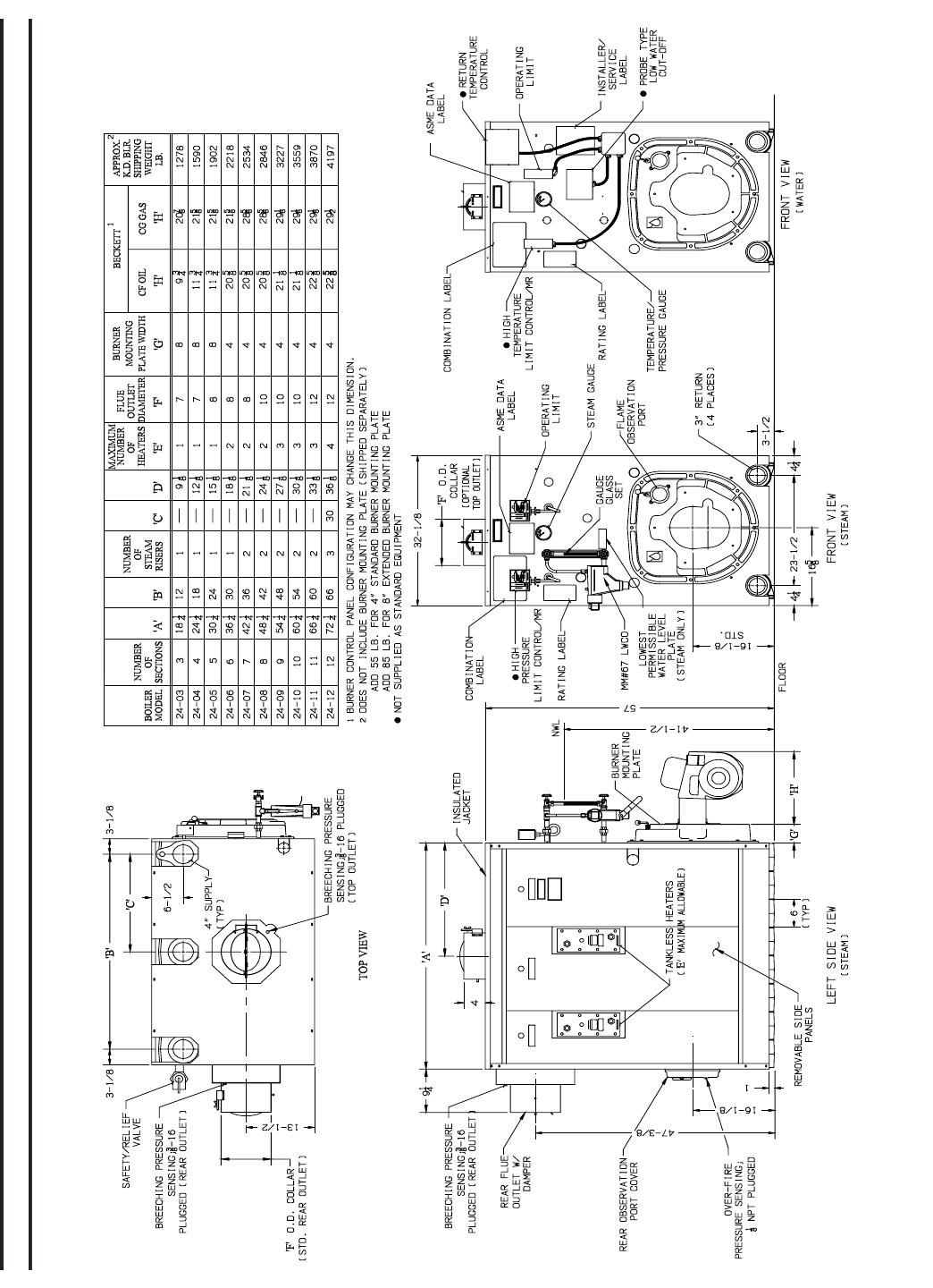
Section I - General Information
FIGURE 1: Dimensional Information

9
TABLE I
BOILER RATINGS/DATA
)1( )2( )3( )4(
relioB
ledoM
-esroH
rewoP
ssorG
tuptuO
)HBM(
gnitaRR=B=IteN renruB
tupnI
gnitaeH
ecafruS
).tF.qS(
teN
xoberiF
emuloV
).tF.uC(
erusserP
ni
xoberiF
).C.W"(
retaW
tnetnoC
).laG(
thgieWrelioB
retaW/w
).sbL( tneV
.aiD
).nI(
.tF.qS
maetS
HBM
maetS
HBM
retaW
liO
)HPG(
saG
)HBM( maetS retaW maetS retaW m
aetS retaW
30-42 2.01 243 1
701 752 792 50.3 834 2.43 0.73 2.3 33. 5.44 0.66 9341 8
161 7
40-42 1.41 174 1
741 353 014 01.4 495 6.84 3.45 8.4 83. 0.35 0.57 1181 5991 7
50-42 9.81 436 3891 674 155 05.5 297 0.36 5.17 4.6 1
3. 5.16 0.48 4812 2732 8
60-42 8.32 797 2942 895 396 09.6 099 5.77 8.88 9.7 8
3. 0.07 0.39 7552 9472 8
70-42 0.82 739 9292 307 518 01.8 4711 9.19 0.601 5.9 6
3. 5.87 0.201 0392 6213 8
80-42 5.23 7801 6933 518 549 04.9 8531 3
.601 3.321 0.11 53. 0.78 0.111 3033 3053 01
90-42 3.93 6131 6414 599 8411 04.11 1461 7.021 5
.041 6.21 53. 5.59 0.021 6763 0883 01
01-42 0.54 5051 8874 9411 9031 00.31 7681 1
.531 8.751 2.41 04. 0.401 0.921 8404 7524 01
11-42 5.05 0961 9245 3031 0741 06.41 3902 5
.941 0.571 7.51 54. 5.211 0.831 1244 4364 21
21-42 3.55 2581 3895 6341 0161 00.61 0232 0
.461 3.291 3.71 94. 0.121 0.741 4974 1105 21
(1) Trim Suffix: S = Steam Boiler, W = Water Boiler
Fuel Suffix: N = Natural Gas, P = LP Gas, O = Oil
(2) I=B=R net ratings shown are based on piping and pick-up allowances which vary from 1.333 to 1.289 for steam and
1.15 for water. Consult manufacturer for installations having unusual piping and pick-up requirements, such as
intermittent system operation, extensive piping systems, etc. The I=B=R burner capacity in GPH is based on oil having a
heat value of 140,000 BTU per gallon.
(3) Firebox volume does not include added volume of 8” extended burner mounting plate (BMP). If 8” BMP is specified
(refer to Figure 1), add 0.7 cu. ft. to volume listed above.
(4) Boiler ratings are based on 12.5% CO2 (oil) and 9.7% CO2 (natural gas), + .10” (inches) water column pressure at boiler
flue outlet. Ratings shown above apply at altitudes up to 1000 feet on oil and 2000 feet on gas.
For altitudes above those indicated, the ratings should be reduced at the rate of 4% for each 1000 feet above sea level.
Maximum Allowable Working Pressure: Steam Boiler - 15 PSI, Water Boiler - 50 PSI
Standard Safety (Relief) Valve Set Pressure: Steam Boiler - 15 PSI, Water Boiler - 30 PSI
10
SECTION I - GENERAL INFORMATION (CONTINUED)
A. INSPECT SHIPMENT carefully for any signs of
damage.
1. ALL EQUIPMENT is carefully manufactured,
inspected and packed. Our responsibility ceases
upon delivery of crated boiler to the carrier in good
condition.
2. ANY CLAIMS for damage or shortage in shipment
must be filed immediately against the carrier by the
consignee. No claims for variances from, or short-
age in orders, will be allowed by the manufacturer
unless presented within sixty (60) days after the
receipt of goods.
3. Make sure that appropriate items on the Master Parts
List (pg 59) are all on hand.
B. LOCATE THE UNIT
1. RECOMMENDED SERVICE CLEARANCE
- Locate the unit in the boiler room so as to
provide ease of venting and adequate clearance
for maintenance, serviceability, and installation of
piping. Refer to Figure 1 for boiler dimensional
data.
FRONT — Provide 43” service clearance for
removal, maintenance, and servicing of burner and
controls.
REAR — Provide a minimum clearance from the
boiler jacket for access to flame observation port,
rear flue damper and vent piping, relief valve, and
boiler return piping. See Table III.
LEFT SIDE — Provide a minimum clearance from
the boiler jacket of 26” for cleaning of flueways and
installation and removal of tankless heater(s).
RIGHT SIDE — Provide a minimum clearance from
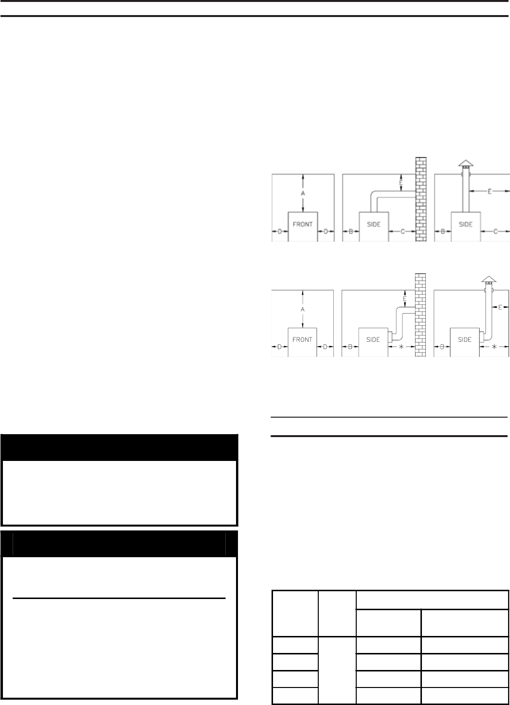
Table II: Minimum Clearances To Combustible
Materials (Inches)
Boilers with Top Flue Outlet
Boilers with Rear Flue Outlet
Flue
Outlet
Size
Top
Flue
Outlet
Rear Flue Outlet
Combustible
Surfaces
Non-Combustible
Surfaces
7" Dia.
18"
37" 22"
8" Dia. 38" 23"
10" Dia. 40" 25"
12" Dia. 43" 28"
NOTICE
Recommended clearance for service may be
reduced to minimum clearance to
combustible material. However, increased
service and maintenance difficulty will
result.
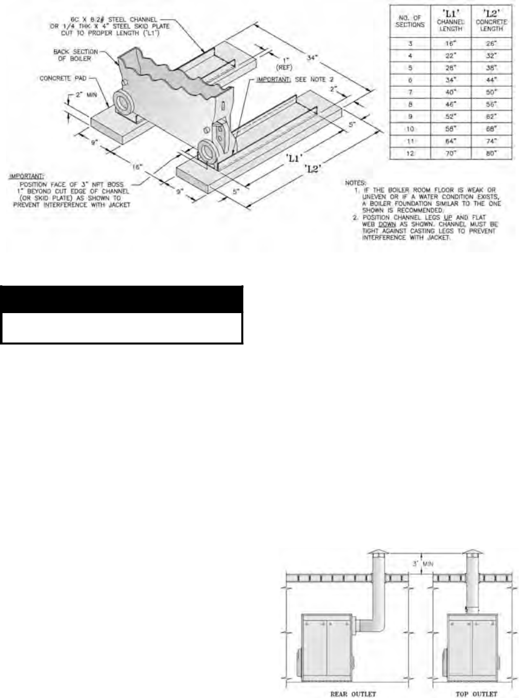
WARNING
Boiler is suitable for installation on
combustible floor. Do not install boiler
on carpeting.
Floor construction should have
adequate load bearing characteristics
to bear the weight of the boiler filled
with water (see Table 1). A boiler
foundation similar to the one shown in
Figure 2 is recommended if the boiler
room floor is weak or uneven or if a
water condition exists.
A
evobA
B
tnorF
C
raeR
D
sediS
E
rotcennoCtneV
6 42 6 6 81
sseccaotecnaraelcecivresdednemmoceRrofIIIelbaTeeS*
reliobforaer
lanoitaNnaciremAhtiwylpmocsecnaraelcdetsiL:1ETON
.tnempiuqegninrubliofonoitallatsnI,13APFN/ISNAdradnatS
htiwsmoornidellatsniebnacsreliob42seireS:2ETON
detsiL.evobadetsilsalairetamelbitsubmocmorfsecnaraelc
tesolcroevoclarofdecuderebtonnacsecnaraelc
.snoitallatsni
,lairetamelbitsubmocotsecnaraelcdecuderroF:3ETON
evobaehtnidebircsedsadedivorpebtsumnoitcetorp
.dradnats13APFN/ISNA
Table III: Recommended Rear Service Clearance
the boiler jacket of 12”.
TOP — Provide a minimum clearance from the
boiler jacket of 24”
2. FOR MINIMUM CLEARANCES to combustible
materials, See Table II.
3. PROVIDE ADEQUATE FOUNDATION for the
unit. Refer to Figure 2.
11
Figure 2: Boiler Foundation
Figure 3a: Typical Arrangement for Stub Vent
C. PROVIDE AIR SUPPLY AND VENTILATION to
accommodate proper combustion.
For commercial and industrial equipment, permanent
facilities for supplying an ample amount of outside air
shall be provided in accordance with the following.
For boiler rooms adjacent to outside walls, and where
combustion air is provided by natural ventilation from
the outside, there shall be a permanent air supply inlet
having a total free area of not less than 1 sq. inch per
4,000 Btu per hr. (35 sq. inch per gallon per hour)
(5.5 cm2 per kw.) of total input rating of the burner or
burners and in no case less than 35 sq. inch (0.425m2).
For boiler rooms not adjacent to outside walls, the
combustion air shall be supplied in a manner acceptable
to the authority having jurisdiction.
1. In the absence of local requirements, the confined
space shall be provided with two permanent
openings, one in or near the top of the room and one
near the bottom. The openings shall communicate
by means of ducts, with the outdoors or to such
spaces (crawl or attic) that communicate with the
outdoors.
a. Where communicating by means of vertical
ducts, each opening shall have a free area of not
less than 1 sq. inch per 4,000 Btuh (35 sq. inch
per gph) (5.5 cm2 per kw) of total input rating of
all appliances in the enclosure.
b. If horizontal ducts are used, each opening shall
have a free area of not less than 1 sq. inch
per 2,000 Btuh (70 sq. inch per gph.) (11 cm2
per kw) of total input of all appliances in the
enclosure.
D. CHIMNEY OR VENT
The Series 24 boiler is designed for forced draft firing
and may be used with a conventional natural draft
stack (15’ minimum height) or a stub vent, sometimes
called a diesel stack (see Figure 3a). See Table I for
the proper vent outlet size. For low silhouette vent
terminations, see Figure 3b. Draft controls are not
normally required, although they may be used on
installations where a natural draft stack is used or on
multiple boiler installations with a common stack. The
boiler is provided with a breeching damper, which
should be adjusted to maintain a positive pressure of
0.1” W.C. in the vent connector box during burner high
fire operation (see breeching pressure sensing port in
Figure 1).
WARNING
Failure to supply adequate air to the boiler
will result in unsafe boiler operation.
12
GNINRAW
fongisedehtnotrepxegnitnevatlusnoC.ylnosnoitadnemmocererasnoitcurtsnIgnitneV
lanoitaNehTdnaediuGgnitneVEARHSAehT.noitacilpparuoyrofmetsystnevcificepsa
.smetsysgnitnevllanideredisnocebdluohs45APFN,edoCsaGleuF
kaelnacsesageulF.noitacilppaehtrofelbatiusebtonyamlairetamtnevlanoitnevnoC
yrujnilanosreperevesnitlusernacdnaslairetamesehtnostniojehtmorfedixonomnobrac
.htaedro
lliwswobleroseetfotnuomaevissecxenarosnurlatnozirohgnolgnivahsnoitallatsnI
foegakaelsageulf,noitasnednocnitlusernacdnasesagnoitsubmocfowolfehttcirtser
.htaedroyrujnilanosreperevesnignitluser,edixonomnobrac
If the venting system is designed for positive or forced
draft venting, the boiler, vent connector and stack will
operate under positive pressure. Gas tight vent systems
designed for pressure systems must be used to prevent
flue by-product leakage. The vent height is usually
limited to prevent negative draft, typically three (3)
feet above the roof line (see Figure 3a). The damper
shall be adjusted to maintain a positive pressure of 0.1”
W.C. in the vent connector box during burner high fire
operation (see breeching pressure sensing port in Figure
1).
If the venting system is designed for negative pressure
(natural draft), the boiler still operates with positive
pressure in the chamber and up to the fixed damper on
the flue collar. However, if the venting system is larger
than what is required, the stack will provide a surplus
draft (or negative pressure) that may require the use of
a barometric damper to maintain the positive 0.1” W.C.
pressure at the flue outlet. Multiple forced draft boiler
stacks should always be designed as negative to ensure
the products of combustion do not exit a boiler that is
not firing.
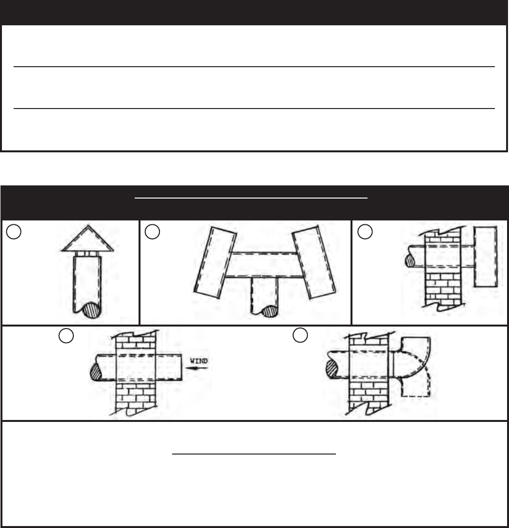
FIGURE 3b: VENTS — FAULTS & SUGGESTIONS
TYPICAL VENTS THAT ARE USED ON FORCED DRAFT BOILERS, ON LOW SILHOUETTE BUILDINGS
VENT SIZING - Area must be the same as or greater than the boiler breeching (Smoke Outlet). A barometric damper may be required on
installations with a high draft condition.
FAULTY BOILER BURNER OPERATION
1. If improper vent is suspected, remove pipe at breeching and operate boiler. This will determine if excessive down draft,
blocked or restricted flue, etc. is causing the problem.
2. If using type shown in A above, be sure cap is raised sufficiently above main pipe to allow flue gases to vent unimpeded.
3. A popular type cap is shown in B.
4. The tee is frequently used as shown in C.
5. D and E should not be used due to possible fluctuations in back pressure.
B
RAIN CAP
RIGHT
“A” CAP
RIGHT
TEE TYPE
RIGHT
DE
WRONG WRONG
90°
ELBOW
UP or DOWN
AC
13
CAUTION
Boiler sections must be drawn-up on
perfectly level surface or improper
assembly may result.
A. FIELD ASSEMBLED SECTIONS — If the boiler
was ordered to be field assembled, follow the assembly
procedure outlined on the following pages.
1. ASSEMBLY OF SECTIONS (MANUAL DRAW-
UP)
These sections are designed to be drawn together,
one section at a time, using the 9¾” long draw-up
rods (provided) and ordinary hand tools.
Tools required:
(1) ¾” Drive Ratchet
(1) 1-1/16” Socket
(1) 1-1/16” Combination or Open End Wrench
(1) Container of grease, oil or other appropriate
lubricant.
CAUTION
When assembling sections without
hydraulic draw-up equipment, never
assemble more than one section at a time.
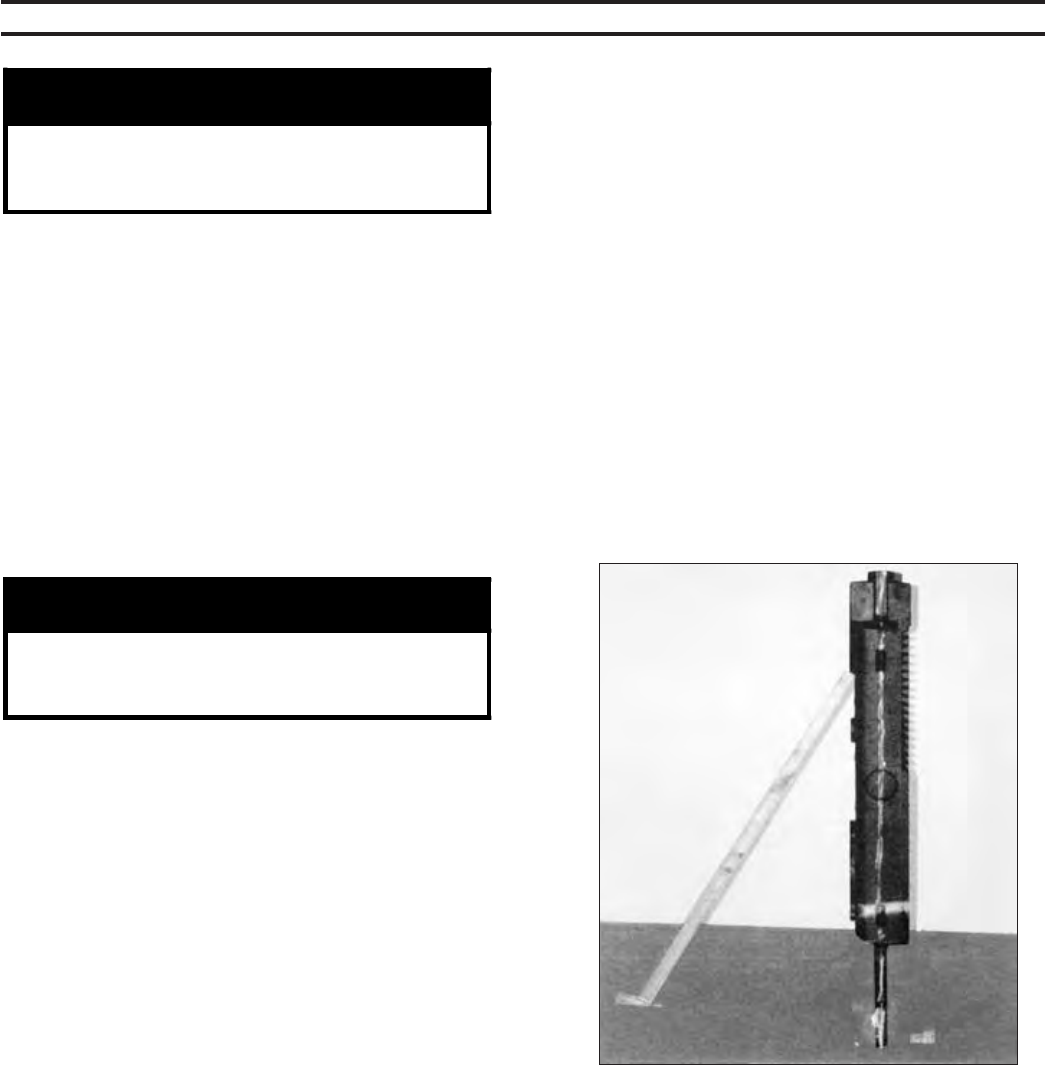
a. Place the rear section in its approximate final
position, as outlined in Section I, and support it
with a suitable prop and wedges. See Figure 5.
b. On size 24-03 only— Open target wall carton,
apply Silastic to back of target wall and secure
target wall to rear section.
c. Clean the groove in the ground joint along the
edge of the section with the wire brush.
d. Open the Boiler Assembly Carton(s) and remove
the bottle of adhesive. Using the dauber supplied
in the bottle, apply the adhesive to the groove.
Be sure to use enough adhesive to sufficiently
coat the entire groove surface. If so desired,
a multi-purpose spray adhesive (supplied by
others) may be used instead. HOWEVER,
GREAT CARE MUST BE TAKEN TO
SECTION II - CAST IRON BLOCK ASSEMBLY
ENSURE THAT THE ADHESIVE DOES
NOT COME IN CONTACT WITH THE
NIPPLES OR NIPPLE PORTS.
e. Clean nipples and nipple ports thoroughly with
a de-greasing solvent. Use the Loctite #592
supplied to lubricate the nipples and nipple
ports. Apply the lubricant to the nipples and
nipple ports, then use a brush to disperse it
evenly around the nipples and the nipple ports.
Use approximately 25 ml of Loctite #592 per
flueway [(1) 7” and (2) 3” nipples and their (6)
corresponding nipple ports].
f. Drive nipples squarely into section using
block of wood and hammer, or preferably,
an aluminum head hammer. (Crown offers a
Polyethylene Block for setting the nipples, part
number 330010). Place block over entire nipple
edge and hit the wood with the hammer.
Figure 5: Positioning of Back Section
14
WARNING
Nipples must be driven in evenly and to
the proper depth to assure tight joints.
Most nipple leaks are caused by tilted
or cocked nipples.
DO NOT use steel/iron head hammer to
drive nipples without using a wood
block. Nipple damage may result.
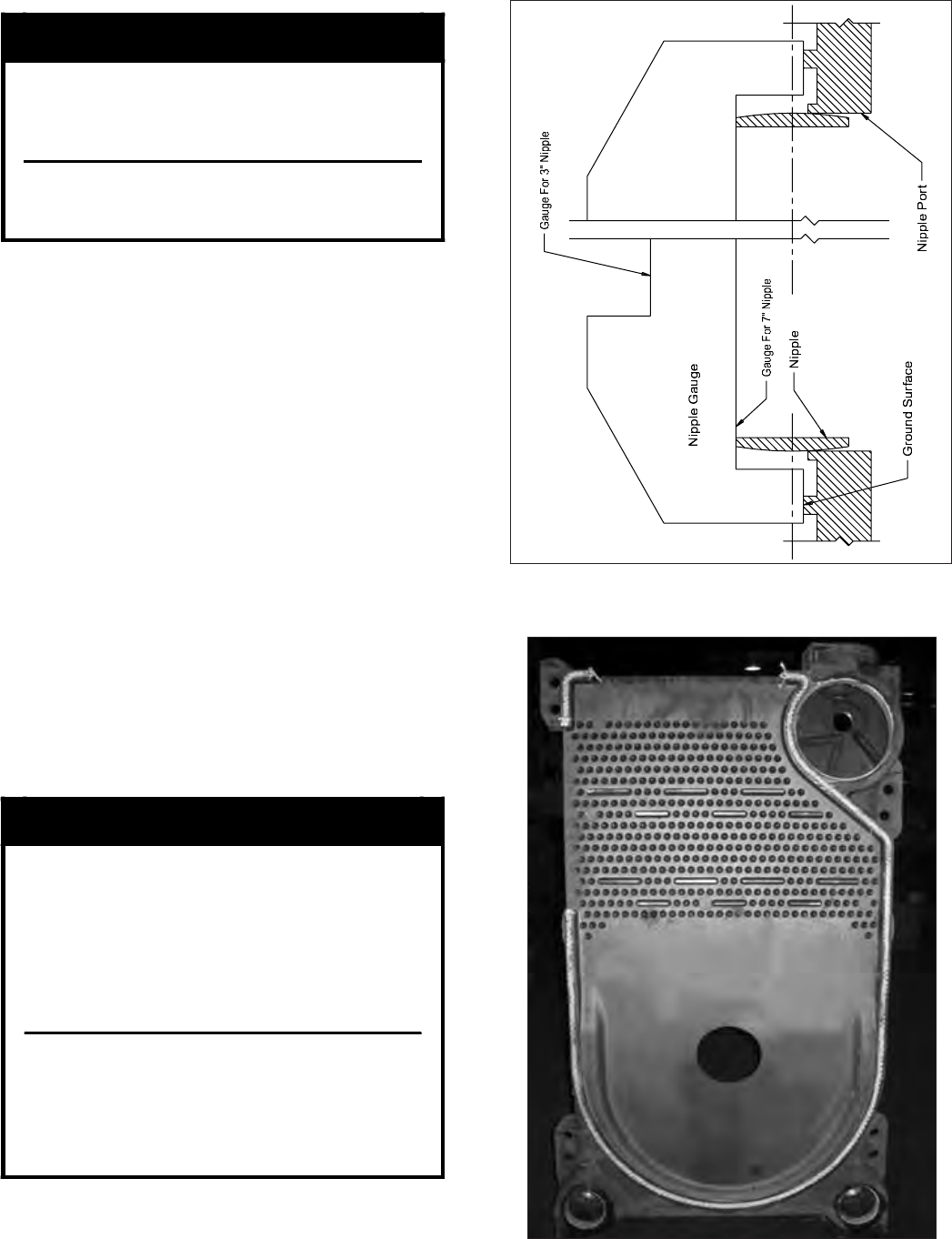
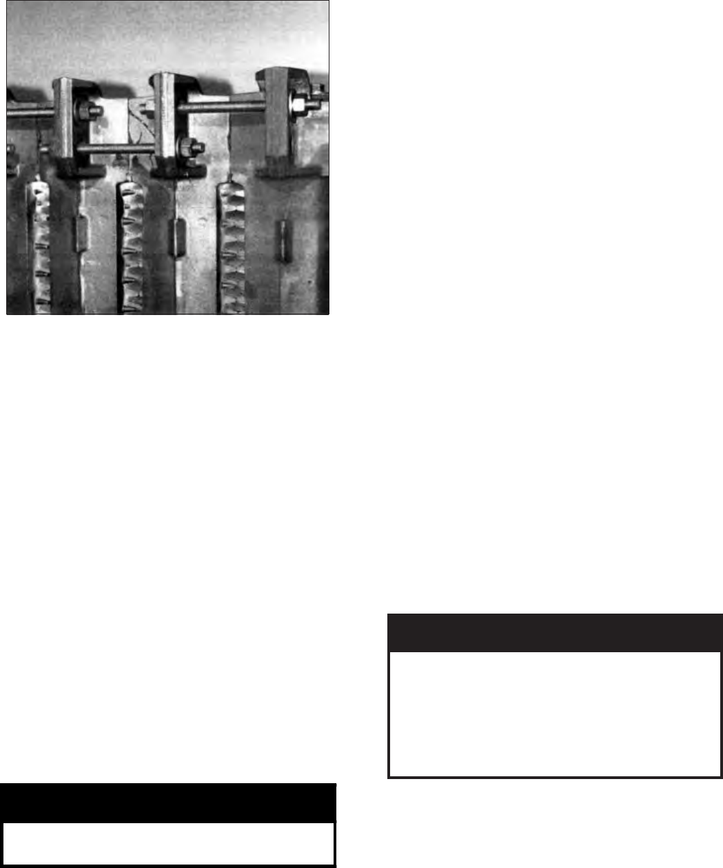
g. A special nipple setting gauge is provided for
the nipples. Gauge nipple in both directions to
insure that it is driven to the proper depth into
the nipple opening (nipple port). Cut-out in
gauge must rest on nipple, with legs of gauge
touching finished face of section, when nipple is
properly driven. See Figure 6.
h. Remove a 96” length of fiberglass rope from the
assembly carton. Starting with the area around
the upper 7” nipple port, firmly press the rope
into the groove, so that the adhesive holds it in
place. (If more than 25 minutes have passed
since the adhesive was applied, it may be
necessary to reapply.) Continue to affix the
rope to the groove in this fashion around the
perimeter of the section. Make sure that the rope
does not droop or hang outside of the groove.
When the end of the groove is reached, cut off
the excess rope. Push the length of excess rope
into the groove at the top corner of the section
face (opposite of the 7” nipple port.) Cut off and
discard any remaining rope after groove is filled.
See Figure 7.
Figure 7: Affixing the Fiberglass Rope
Figure 6: Nipple Gauge
WARNING
Sections must be drawn-up tight
immediately after properly applying
sealant for best results. Although
sections may be joined within two (2)
hours of applying sealant, humidity and
temperature affect cure time. If a "thick
skin" has been formed on the sealant
bead, remove and re-apply sealant.
Sealant must be properly applied to
ALL grooves. Failure to properly seal
the boiler joints will result in
combustion gas leaks through the joint.
DO NOT operate boiler with
combustion gas leaks.
15
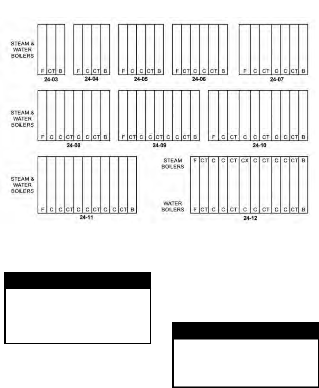
i. From the “Section Arrangement” chart, select
the next section according to the “Identification
Code” at the top of the chart. See Figure 8. Use
a wire brush to clean the groove in the face of
the next section. Then, using a cartridge of RTV
6500 or RTV 736 sealant in a caulking gun, fill
the groove in this section with silastic sealant.
Touch-up any missed spots before draw-up.
Touch-up after draw-up has no value.
j. Clean and lubricate nipple ports on next section
to be assembled and place on nipples previously
installed in rear section. To facilitate assembly,
it is advisable to enter the upper nipple first in
its port. Then enter the lower nipples in their
respective ports. If necessary, place a lifting bar
(crowbar) under the center of the section and lift
the nipple port onto the upper nipple.
k. Drive section in place with a heavy block of
wood, striking blows as squarely as possible over
nipple port.
l. The large draw-up rod lugs with dual holes
are cast in the four (4) corners of each casting.
Starting with the upper holes, install four
(4) 5/8” x 9¾” long draw-up rods along with
washers and nuts (see Figure 9).
NOTICE
The sections must be assembled according
to the arrangement shown to ensure proper
operation, proper assembly of canopy,
jacket and alignment of piping and tankless
heaters with jacket knockouts. Start with
the back section and work towards the
front.
CAUTION
To avoid damage to the draw-up rod
threads while drawing up sections, apply
oil or other lubricant to tie rod threads
while assembling sections to prevent
stripping of threads on rod and to make
assembling easier.
BOILER SECTION IDENTIFICATION CODE
F = FRONT SECTION WITH 4” SUPPLY TAPPING C = CENTER SECTION
B = BACK SECTION WITH 4” SUPPLY TAPPING CX = CENTER SECTION WITH 4” TOP SUPPLY TAPPING
NOTES: FOR BOILERS LESS TANKLESS HEATER, REPLACE THE “CT” SECTIONS WITH “C” SECTIONS.
Figure 8: Series 24 Section Arrangement
m. DRAW UP SECTION SLOWLY AND
EVENLY using an alternating pattern starting
with the upper right lug and proceeding to the
lower left , lower right and finishing with upper
left lug.
16
When you start, grind surfaces between
adjoining sections should be approximately
3/8” apart. Use three (3) or four (4) passes at
tightening the four (4) draw-up rods a little at
a time so that sections are pulled up evenly.
During the last pass, pay close attention to the
silastic sealant as it squeezes when the sections
come in close contact. The silastic sealant will
continue to squeeze out wafer thin until the
sections are connected metal to metal. While
tightening the nuts, close attention should be
given to the connection area to determine that
the silastic has stopped squeezing out from
between the sections. This will give assurance
that the sections are assembled metal to metal. If
the silastic has stopped squeezing out from the
connection and the sections still do not appear
to be drawn metal to metal, measure any gaps
between the sections with a feeler gauge. A
maximum gap of .025” is acceptable. Gaps
should be measured at the outer edge of the
connection. DO NOT PUNCTURE THE
GASKET CREATED BY THE FIBERGLASS
ROPE AND SILASTIC
SEALANT WITH THE FEELER GAUGE.
WARNING
Do not over torque draw up nuts after grind
surfaces meet.
KEEP NIPPLES ALIGNED WITH NIPPLE
PORTS. If necessary, tap edge of nipples lightly
with a blunt tool or rod to keep nipples from
cocking while sections are being drawn-up. DO
NOT DRAW UP SECTION WHEN NIPPLES
ARE COCKED. If the torque required becomes
Figure 9: Draw-Up Rods (Alternating Pattern -
Manual Draw-up)
2. ASSEMBLY OF SECTIONS (HYDRAULIC DRAW-
UP)
The entire boiler assembly may be drawn up at one
time using hydraulic draw-up equipment providing
the operation is completed within four (4) hours after
application of the sealant.
a. Repeat steps 1a through 1k under “Field
Assembled Sections (Manual Draw-Up).”
b. Continue driving sections in place (in their
respective order) until all sections are in the
assembly. Ground surfaces between adjoining
sections should be spaced 1/4” to 3/8” apart.
Spacing of more than 3/8” will limit number of
sections that can be drawn up in one unit and
could indicate cocked nipples.
On long boiler assemblies, it may be necessary to
draw-up a partial block if the entire boiler is not
ready to be drawn-up tight within four (4) hours
of the first application of Silastic. If the block
assembly time extends overnight, the partial block
completed must be drawn-up tight before leaving
the boiler overnight. If a joint springs out, it must
be redrawn tight within four (4) hours of first
application of Silastic to the joint.
c. Insert the three (3) ¾” draw-up rods (and
couplings, if appropriate) through the tapped holes
in the rear section extending them through the
excessive, periodically place a heavy block of
wood over each nipple port and strike as squarely
as possible with several blows to relieve tension
on the draw-up rods.
n. CONTINUE ASSEMBLING SECTIONS IN
THEIR RESPECTIVE ORDER alternating
the draw-up rods from the upper to lower set
of holes in draw-up lugs. Be certain that all
sections are drawn up IRON-TO-IRON at all
three (3) nipple ports.
BE SURE TO APPLY THE SEALANT to
the groove in the ground joints between
adjacent sections as the boiler operates with a
positive pressure in the firebox and products of
combustion will escape between sections unless
the sections are properly sealed. The sealant
should be applied before each section is placed
on the assembly.
o. If a joint springs apart it must be redrawn tight
within four (4) hours of the time of application of
Silastic to that joint.
GNINRAW
LLAotdeilppaylreporpebtsumtnalaeS
reliobehtlaesylreporpoteruliaF.sevoorg
skaelsagnoitsubmocnitluserlliwstnioj
reliobetarepoTONOD.tniojothguorht
tnalaesehT.skaelsagnoitsubmochtiw
sinoitceshcaeerofebdeilppaebdluohs
.ylbmessaehtnodecalp
17
Figure 11: Center Section Channel Block Position
(Partial Block Draw-Up)
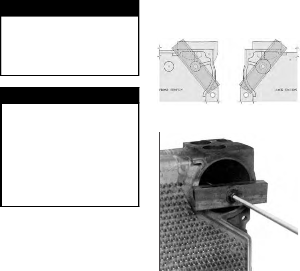
Figure 10: Front and Rear Section Channel
Block Positions (Hydraulic Draw-up)
CAUTION
Do not apply pressure directly on threaded
tappings on front and rear sections with
draw-up channels during assembly
procedures.
Rods should be approximately centered in
openings so that rods and couplings (when
used) do not drag on pipe thread in end
section tappings.
WARNING
READ THE STATEMENTS BELOW BEFORE
ATTEMPTING TO USE HYDRAULIC EQUIPMENT.
*
*
*
*
Release pressure in ram pumps before
attempting to remove clamps.
Do not stand in line with draw-up rods at
either end when hydraulic pressure is
being applied. As a safety measure,
ends of draw-up rods should be covered
while sections are being drawn in case
rods should snap while under tension.
Do not operate ram against draw-up
coupling.
Do not operate pump after ram has
reached stroke limit.
e. Draw-Up Sections
Use hydraulic rams to draw up sections by
applying pressure alternately on the draw-up
rods. When rams reach stroke limit, release
pressure in ram pumps and then move clamps to
new position.
f. Continue to draw-up until all sections make
contact at the ground joints.
g. After all sections have been drawn up, but before
removing the hydraulic rams and draw-up rods,
the 9¾” long tie rods must be installed.
The large draw-up rod lugs with dual holes
are cast in the four (4) corners of each casting.
Starting with the upper holes in the back section,
install four (4) 5/8” x 9¾” long tie rods along
with washers and nuts. Continue installing the
tie rods alternating from the upper to lower set
of holes in draw-up lugs until front section is
secured. Be certain that all sections are drawn
up IRON TO IRON at all three nipple ports.
h. Excess length of draw-up rods must not extend
beyond front and rear section. To ensure proper
fit of jacket, adjust accordingly. Tighten all tie
rod nuts until finger tight. Then tighten them
an additional ½ turn with a wrench to prevent
section damage to thermal expansion.
tapped holes in the front section. Be sure to
screw draw-up rods into couplings far enough to
prevent stripping threads.
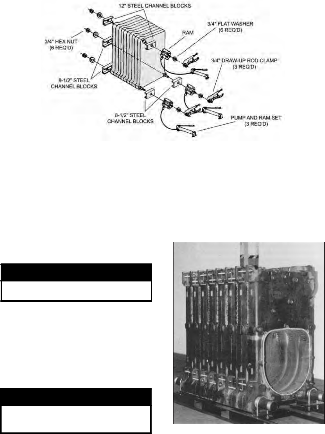
d. Place a 3” x 12” lg. steel channel on each end of
the upper draw-up rod and a 3” x 8½” lg. steel
channel on each end of the lower draw-up rods.
Refer to Figures 10 and 11 for proper placement
of channel block during assembly procedures.
Install nuts and washers on one end of the draw-
up rods and the hydraulic rams, washers and
draw-up rod clamps on the other. See Figure 13.
18
Figure 12: Hydraulic Draw-Up of Sections
B. HYDROSTATIC TEST — After the boiler sections
have been assembled, it is essential that the boiler be
hydrostatically tested before the canopy, flue cover
plates, jacket, or piping is installed.
1. Tankless Heater Installation
If boiler is ordered with tankless heaters, install
heaters with the gaskets provided. Table IV
on Page 37 gives the maximum number of heaters
permissible per assembly and the heater ratings.
2. Plug all boiler tappings and fill boiler completely
with cold water.
Figure 13: Boiler Section Assembly
4. EXAMINE BOILER CAREFULLY, INSIDE AND
OUTSIDE, to insure against leaks from cocked
nipples or through concealed breakage caused in
shipping and handling. This precaution is for your
protection and will simplify handling of necessary
replacements and adjustment claims.
5. After making certain that there are no leaks, drain
boiler and remove plugs for boiler trim and other
connections.
3. All completed boilers must satisfactorily pass the
prescribed hydrostatic test.
a. STEAM BOILERS: The assembled boiler must
be subjected to a hydrostatic test of 45 psig to 55
psig.
b. HOT WATER BOILERS: The assembled boiler
must be subjected to a hydrostatic test of not less
than 1½ times the maximum allowable working
pressure (MAWP).
CAUTION
DO NOT install gauge until after hydrostatic
testing the boiler. Gauge failure may result.
WARNING
Failure to properly hydrotest all boilers at
the correct pressure may result in section
assembly failure in operation.
19
SECTION III - INSTALLATION INSTRUCTIONS
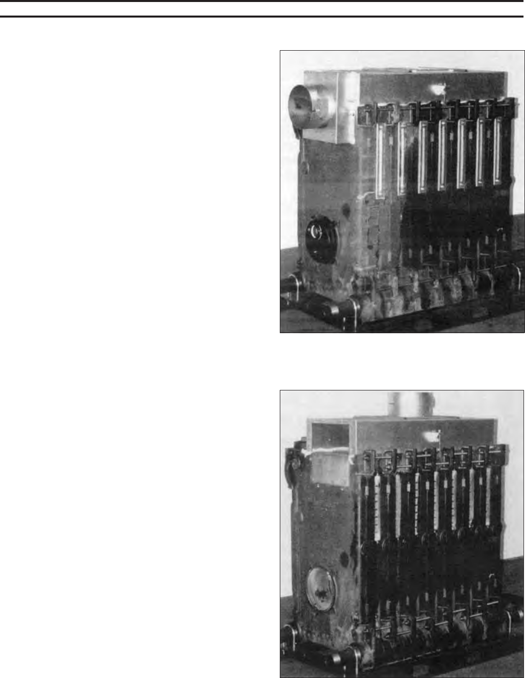
A. INSTALL CANOPY/FLUE OUTLET ASSEMBLY,
Refer to Figures 14, 15 and 16.
1. Open canopy carton.
2. Attach the two (2) canopy brackets to the front end
cap of canopy with four (4) #10 x 1/2” sheet metal
screws each.
3. Across the top of the front section and along the top
ledges running back each side of the sections, place
continuous 2” wide strips of cerafelt and overlap
joints at front corners. Cerafelt strip should extend
1/4” beyond rear surface of back section. Cut off
excess.
4. Place the canopy on the sections.
5. Position rear flange (end with studs) of canopy flush
with rear surface of back section.
6. Loosely attach the canopy brackets to the lugs on
the front section of the block assembly with 5/16”
carriage bolts, flat washers and locknuts.
7. Check to see if rear flange of canopy is still flush
with raised flange on back section.
8. Open either the rear flue outlet carton (standard) or
top flue outlet carton (optional).
9. Attach the 1/8” x 1” wide self-adhesive fiber gasket
to the surface of either the rear flue outlet damper
assembly or rear flue outlet cover that mounts
against the canopy and back section. Gasket must
be centered over all attachment holes. Do not
overlap corners, cut butt joints.
10. Attach either the rear flue outlet damper assembly
or rear outlet canopy cover to the canopy with the
5/16” flat washers, lock-washers and brass
nuts and tighten securely. Attach the rear flue
outlet damper assembly or cover to the back section
with the four (4) 5/16” flat washers and cap screws
and tighten securely.
11. Tighten front canopy carriage bolt until canopy is
secure.
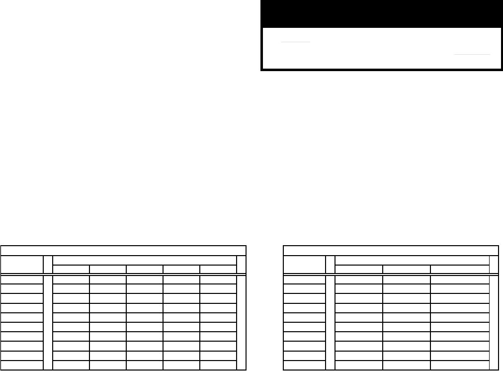
12. On the longer canopy sizes, Intermediate Mounting
Brackets are provided, two (2) are required on sizes
24-07 thru 24-09 and four (4) are required on sizes
24-10 thru 24-12A. Refer to Figures 17 and 18.
a. Intermediate brackets are shipped flat. Bend
side flanges down approximately 90° as shown.
Adjust bends until holes in bracket match hole
pattern on canopy.
b. Secure brackets to both sides of canopy with
three (3) #10 x ½” sheet metal screws per
bracket.
c. Secure canopy left side bracket(s) with
appropriate canopy ‘J’ bolt(s). Insert threaded
end through holes in brackets and hook ‘J’ bolt
on center section draw-up rod (hooks should
Figure 14: Canopy with Rear Flue Outlet
Damper Assembly
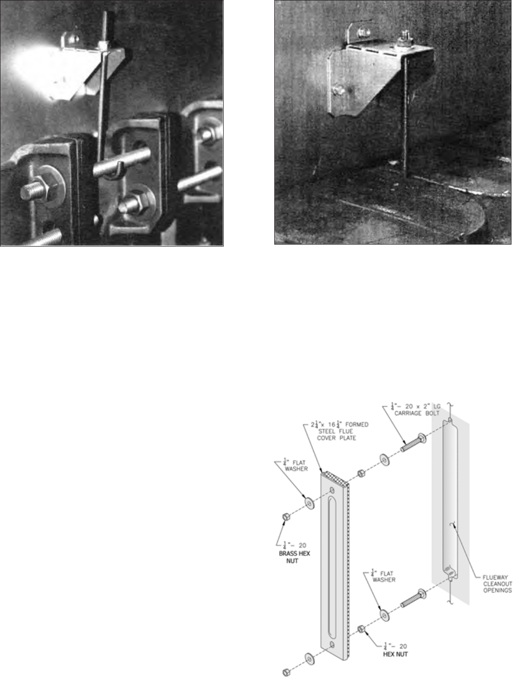
Figure 15: Canopy with Top Flue Outlet
Damper Assembly (Rear Cover Removed)

20
Figure 16: Bare Boiler Assembly

21
Warning:
This product contains refractory ceramic fibers (RCF). RCF has been classified
as a possible human carcinogen. After this product is fired, RCF may, when
exposed to extremely high temperature (>1800F), change into a known human
carcinogen. When disturbed as a result of servicing or repair, RCF becomes
airborne and, if inhaled, may be hazardous to your health.
AVOID Breathing Fiber Particulates and Dust
Precautionary Measures:
Do not remove or replace previously fired RCF (combustion chamber insulation,
target walls, canopy gasket, flue cover gasket, etc.) or attempt any service or
repair work involving RCF without wearing the following protective gear:
1. A National Institute for Occupational Safety and Health (NIOSH) ap-
proved respirator
2. Long sleeved, loose fitting clothing
3. Gloves
4. Eye Protection
• Take steps to assure adequate ventilation.
• Wash all exposed body areas gently with soap and water after contact.
• Wash work clothes separately from other laundry and rinse washing ma-
chine after use to avoid contaminating other clothes.
• Discard used RCF components by sealing in an air tight plastic bag.
First Aid Procedures:
• If contact with eyes: Flush with water for at least 15 minutes. Seek
immediate medical attention if irritation persists.
• If contact with skin: Wash affected area gently with soap and water.
Seek immediate medical attention if irritation persists.
• If breathing difficulty develops: Leave the area and move to a loca-
tion with clean fresh air. Seek immediate medical attention if breath-
ing difficulties persist.
• Ingestion: Do not induce vomiting. Drink plenty of water. Seek im-
mediate medical attention.
Important Product Safety Information
Refractory Ceramic Fiber Product
22
face outward). Secure canopy with 5/16” flat
washers, lock washers and brass nuts. See
Figure 17.
d. Secure canopy right side bracket(s) with ¼ - 20
x 5” lg. carriage bolts. Insert head of carriage
bolt between canopy body and casting. Slide
carriage bolt into slot provided between castings.
Lower carriage bolt until threaded end will pass
through hole in bracket. Secure canopy with ¼”
flat washers, lock washers and brass nuts. See
Figure 18.
13. Attach the 1/8” x 1” wide self-adhesive fiber gasket
to the surfaces of either the top flue outlet damper
assembly or top outlet canopy cover that mounts
against the canopy. Gasket must be centered over
all attachment holes. Do not overlap corners, cut
butt joints.
14. Secure either the top flue outlet damper assembly or
top outlet canopy cover with #10 x 1/2” sheet metal
screws.
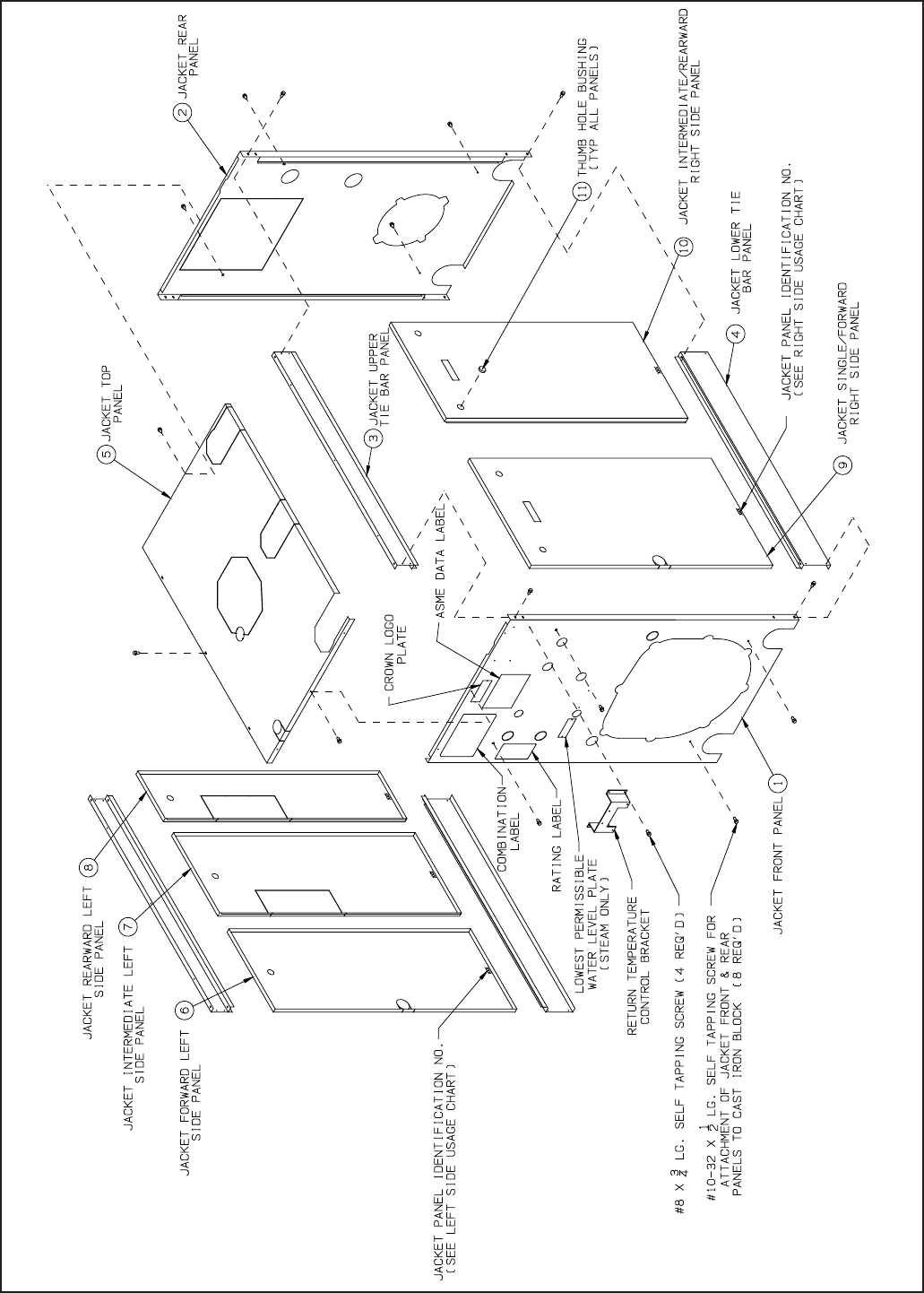
B. INSTALL FLUE COVER PLATES over cleanout
openings on left side of boiler as shown in Figure 19.
See Important Product Safety Information on Page
21 of this manual, regarding refractory ceramic
fiber product warning.
1. Locate the cover plates, carriage bolts, nuts and
washers in the boiler assembly carton(s).
2. Remove insulation from two (2) 3/8” diameter holes
in flue cover plates using a 3/8” drill bit. Rotate bit
through insulation by hand.
3. Attach the carriage bolts to the top and bottom of the
flue openings with washers and hex nuts to provide
a fixed stud.
4. Install flue cover plates over studs with insulation
Figure 17: Left Side Canopy Intermediate Bracket Figure 18: Right Side Canopy Intermediate Bracket
against boiler and secure with washers and nuts.
Tighten until insulation on cover plate provides a
tight seal to casting. If after tightening, a gap is still
evident where the sections join, apply silastic along
top and bottom edge of insulation board.
5. Repeat steps 3 through 6 for mounting remaining
flue cover plates.
Figure 19: Flue Cover Plate Attachment
23
C. MOUNT REAR OBSERVATION PORT COVER
Refer to Figure 16.
1. With the silastic sealant, secure the 3/16” diameter
rope gasket into the groove around the perimeter of
the rear observation port cover.
2. Mount the rear observation port cover onto the rear
section (with the word “Top” in the upright position)
using the four (4) 5/16” - 18 x 1” lg. cap screws and
flat washers provided.
D. INSPECT ALL BOILER SEALS
1. A visual inspection should be made of all sealed
joints and repairs made as necessary. Darken
the boiler room and place a light source in the
combustion space and canopy to observe any gaps
or open seals. Poor seals must be repaired and
rechecked before continuing.
E. JACKET ASSEMBLY - See Figure 22 for Jacket
Assembly Details.
1. Open jacket carton and jacket hardware package.
Unless otherwise stated, all jacket components are
fastened with #8 x ½” hex head sheet metal screws.
Do not drive sheet metal screws tight until jacket
assembly is complete.
2. On boilers with rear flue outlet damper assembly,
remove square knockout from jacket rear panel. To
remove knockout, use a single hacksaw blade with
handle or aviation snips to cut metal tabs between
slotted holes.
3. Attach jacket front panel to front section and jacket
rear panel to back section using the eight (8) #10
x ½” self tapping screws. Tighten these screws
securely.
4. Attach jacket lower tie bar panel (approximately
5-5/8” high) to the bottom of the jacket front and
rear panels using four (4) sheet metal screws.
Repeat for opposite side.
5. Attach jacket upper tie bar panel (approximately
4-1/8” high) to the top of the jacket front and rear
panels using four (4) sheet metal screws. Repeat for
opposite side.
6. Jacket Top Panel Attachment
a. On boilers with top flue outlet damper assembly,
remove octagon shaped knockout. To remove
knockout, use a single hacksaw blade with handle
or aviation snips to cut metal tabs between
slotted holes.
b. Remove knockout(s) for necessary supply piping
in a similar manner.
c. Attach jacket top panel to the front panel, rear
panel and upper tie bar panels with sheet metal
screws.
7. Install Jacket side Panels
a. Snap black thumb hole bushings into all side
panel holes.
b. Use the left side panel and right side panel usage
charts to determine correct positions of side
panels. The three (3) digit panel identification
numbers shown in the charts are also stamped
along the bottom edge of each panel. Refer to
Figures 20 and 21.
c. Rearward and Intermediate panels have reverse
bend flanges on one side of panel. These panels
must be installed prior to forward panels.
NOTICE
To install multiple side panels, start at the
rear of boiler and work forward. To remove
panels, reverse order of assembly.
d. If boiler is equipped with tankless heaters they
should be installed at this time if they were not
installed for hydrostatic test outlined on Page 18.
e. Install right side panels into position by inserting
top of panel into ‘U’ shaped channel, pushing
bottom of panel in toward boiler, and sliding
panel down into ‘J’ shaped channel. Repeat
procedure until all right side panels are in place.
f. Remove the knockouts necessary for tankless
heater operation on left side panels.
g. Install left side panels, using the same procedure
used to install the right side panels.
Figure 20: Left Side Panel Usage Chart Figure 21: Right Side Panel Usage Chart
PANEL 1 PANEL 2 PANEL 3 PANEL 4 PANEL 5 PANEL 3 PANEL 2 PANEL 1
24-03 L10 L5 - - - 24-03 - - R15 (SINGLE)
24-04 L10 L11 - - - 24-04 - - R21 (SINGLE)
24-05 L10 L17 - - - 24-05 - - R27 (SINGLE)
24-06 L10 L18 L5 - - 24-06 - - R33 (SINGLE)
24-07 L10 L18 L11 - - 24-07 - R15 R24
24-08 L10 L18 L17 - - 24-08 - R21 R24
24-09 L10 L18 L18 L5 - 24-09 - R27 R24
24-10 L10 L18 L18 L11 - 24-10 - R27 R30
24-11 L10 L18 L18 L17 - 24-11 - R33 R30
24-12 L10 L18 L18 L18 L5 24-12 R21 R24 R24
JACKET LEFT SIDE PANEL USAGE CHART RIGHT SIDE PANEL USAGE CHART
BOILER
MODEL
BOILER
MODEL
SINGLE / MULTIPLE RIGHT SIDE PANELS*MULTIPLE LEFT SIDE PANELS*
*NOTE: TO INSTALL MULTIPLE SIDE PANELS, START AT THE REAR AND WORK FORWARD. TO REMOVE PANELS, REVERSE ORDER OF ASSEMBLY.
REAR OF BOILER
FRONT OF BOILER
FRONT OF BOILER
REAR OF BOILER
24
Figure 22: Series 24 Jacket Assembly (Boiler Models 24-03 thru 24-12)
25
8. Combination Label and Crown Logo Plate were
attached to jacket front panel at time of manufacture.
If loose or peeling, apply pressure to reset adhesive.
9. On steam boilers, attach lowest permissible water
level plate (from steam trim carton) to the front
panel using sheet metal screws.
10. Tighten all sheet metal screws to complete jacket
assembly.
11. RTC Bracket (if used)- install bracket in top right
corner of front panel with four (4) #8 x 3/4” self
tapping screws.
F. BURNER MOUNTING PLATE - Refer to Figures 16
and 23.
1. Using silastic sealant, secure the 3/16” diameter
rope gasket to the groove along the mounting plate
opening in the front section.
2. Install 5/16” x 1” lg. cap screw in lower tapping on
front section to carry weight of burner mounting
plate.
3. Engage bottom slot on burner mounting plate with
matching bolt in bottom tapping of front section.
Align mounting holes and fasten the mounting plate
to the boiler sections with seven (7) remaining 5/16”
cap screws and washers. Fully tighten all bolts.
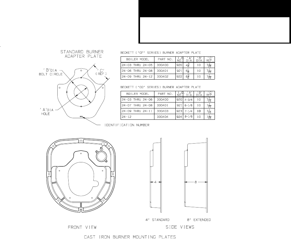
G. MOUNT BURNER ADAPTER PLATE TO
BURNER MOUNTING PLATE.
Refer to Figures 16 and 23.
1. In all cases the burner adapter plate carton for the
specified burner will be provided by Crown.
2. Open Adaptor Plate carton and remove contents.
CAUTION
Failure to properly fill all gaps between the
insulation and burner blast tube may result
in damage to the burner
Apply four (4) small dabs of silastic on rear surface
of adapter plate to temporarily hold gasket in
place. Hold adapter plate in position against burner
mounting plate, align holes and secure with five (5)
3/8” lock washers and 3/8” x 7/8” lg. cap screws.
3. Follow burner manufacturer’s instructions using
gasket material and hardware provided with burner.
4. USE A HOLE SAW OR KNIFE TO CUT BURNER
MOUNTING PLATE INSULATION TO MATCH
HOLE SIZE ON BURNER ADAPTER PLATE.
After cutting, remove any and all loose pieces of
insulation which may become lodged or interfere
with the head of a burner air tube after insertion.
Confirm that hole in insulation fits snugly around
burner blast tube. If hole is oversized, use fiberglass
rope gasket provided with burner to fill in any space
between insulation and blast tube. If rope gasket
is not provided with the burner, use 3/8” fiberglass
rope (provided by others).
5. For boilers without tankless heaters, proceed
to Step H (Install Steam Trim) or I (Install Water
Trim).
6. For boilers with tankless heaters, install the
tankless heater manifolds according to Figure 37.
Figure 23: Burner Mounting Plate/Burner Adapter Plate Options
26
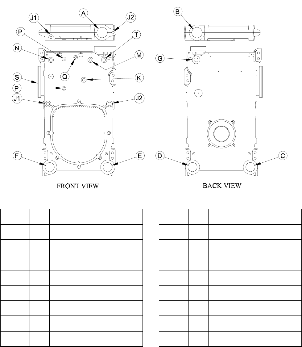
Figure 25a Purpose of Tappings - Steam Boilers
Size Size
(in) (in)
B 4 Plug (24-03 thru 24-06)
Supply (24-07 thru 24-12) K
Steam Boiler
A 4 Supply
Tapping
Location Steam Boiler Tapping
Location
C3 Blow-Off Valve
D 3 Return
E 3 Plug
J1 1
F 3 Plug
G 1-1/2 Safety Valve/Surface Skim Tap
Plug
J2 1 Float L.W.C.O.
3/4 Plug
M 3/4 Operating Pressure Limit Control
N 3/4 Hi Pressure
Limit Control/Manual Reset
P 1/2 Gauge Glass/#67 L.W.C.O.
Q 1/2 Steam Gauge (Bush to 1/4")
S 3/4 Tankless Heater Control
T 3/4 Firing Rate Pressure Control
27
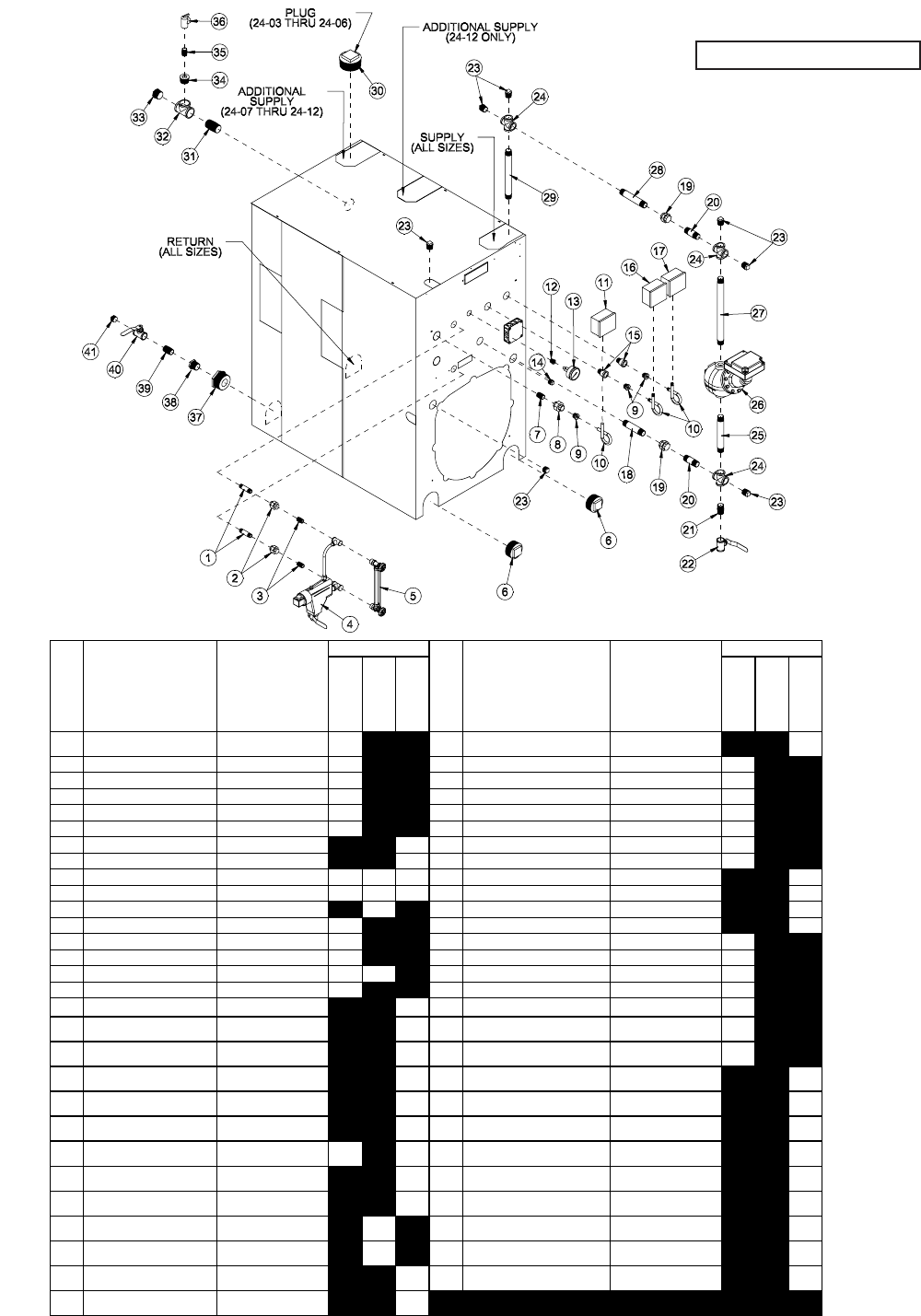
1 1/2" X 3" BR NIPPLE ALL 2 29 1" X 12" NIPPLE CSD-1 EQUIPPED BOILERS
PUMPED RETURN 1
2 1/2" BR UNION ALL 2 30 4" BK PLUG ALL 1
3 1/2" BR CLOSE NIPPLE ALL 2 31 1-1/2" X 4 NIPPLE ALL 1
4 LWCO, #67 ALL 2 32 1-1/2" TEE ALL 1
5 GAUGE GLASS SET ALL 2 33 1-1/2" SQ. HD. PLUG ALL 1
6 3" SQ. HD. PLUG ALL 2 34 1-1/2" x 3/4" BLK BUSHING 24-03 1
7 3/4" X 2" NIPPLE ALL 1 34 1-1/2" x 1" BLK BUSHING 24-04 1
8 3/4" UNION ALL 1 34 1-1/2" x 1-1/4" BLK BUSHING 24-05 THRU 24-08 1
9 3/4" X 1/4" HEX BUSHING ALL 1 1 1 35 3/4" CLOSE NIPPLE 24-03 1
10 1/4" 90° BR PIGTAIL ALL 1 1 1 35 1" CLOSE NIPPLE 24-04 1
11 L404C1147 CSD-1 EQUIPPED BOILERS 1 35 1-1/4" CLOSE NIPPLE 24-05 THRU 24-08 1
12 1/2" X 1/4" BR BUSHING ALL 1 35 1-1/2" CLOSE NIPPLE 24-09 THRU 24-12 1
13 PRESSURE GAUGE ALL 1 36 SAFETY VALVE 13-211 24-03 1
14 3/4" RECESSED HD PLUG ALL 1 36 SAFETY VALVE 13-202 24-04 1
15 3/4" BLK EXTENSION ALL 1 1 36 SAFETY VALVE 13-213 24-05 THRU 24-08 1
16 L404F1367 ALL 1 36 SAFETY VALVE 13-214 24-09 THRU 24-12 1
17 FIRING RATE PRES CTRL MODULATING BOILERS 1 37 3" X 1-1/4" BLK BUSHING ALL 1
18 1" X 5-1/2" NIPPLE CSD-1 EQUIPPED BOILERS
PUMPED RETURN 1 38 1-1/4" X 3/4" BUSHING 24-03 THRU 24-04 1
19 1" UNION CSD-1 EQUIPPED BOILERS
PUMPED RETURN 2 38 1-1/4" X 1" BUSHING 24-05 THRU 24-08 1
20 1" X 3-1/2" NIPPLE CSD-1 EQUIPPED BOILERS
PUMPED RETURN 2 39 3/4" CLOSE NIPPLE 24-03 THRU 24-04 1
21 1" CLOSE NIPPLE CSD-1 EQUIPPED BOILERS
PUMPED RETURN 1 39 1" CLOSE NIPPLE 24-05 THRU 24-08 1
22 1" BALL VALVE CSD-1 EQUIPPED BOILERS
PUMPED RETURN 1 39 1-1/4" CLOSE NIPPLE 24-09 THRU 24-12 1
23 1" RECESSED HD PLUG CSD-1 EQUIPPED BOILERS
PUMPED RETURN 4 3 40 3/4" BALL VALVE 24-03 THRU 24-04 1
24 1" CROSS CSD-1 EQUIPPED BOILERS
PUMPED RETURN 3 40 1" BALL VALVE 24-05 THRU 24-08 1
25 1" NIPPLE* CSD-1 EQUIPPED BOILERS
PUMPED RETURN 1 40 1-1/4" BALL VALVE 24-09 THRU 24-12 1
26 #150-MD LWCO CSD-1 EQUIPPED BOILERS
PUMPED RETURN 1 41 3/4" SQ. HD. PLUG 24-03 THRU 24-04 1
26 #64 LWCO CSD-1 EQUIPPED BOILERS
GRAVITY RETURN 1 41 1" SQ. HD. PLUG 24-05 THRU 24-08 1
27 1" NIPPLE** CSD-1 EQUIPPED BOILERS
PUMPED RETURN 1 41 1-1/4" SQ. HD. PLUG 24-09 THRU 24-12 1
28 1" NIPPLE*** CSD-1 EQUIPPED BOILERS
PUMPED RETURN 1
*SIZE NIPPLE TO SET WATER LEVEL OF LWCO.
**SIZE NIPPLE TO MAKE UP LENGTH BETWEEN 24 & 26.
QUANTITY
KEY DESCRIPTION BOILER MODELS DESCRIPTION BOILER MODELS
QUANTITY
KEY
OPTIONAL
NOT
SUPPLIED
STANDARD
***SIZE NIPPLE TO MAKE UP LENGTH BETWEEN 19 & 24.
STANDARD
OPTIONAL
NOT
SUPPLIED
Figure 25b: Steam Trim

28
WARNING
Safety valve discharge piping must be
piped to within six (6) inches of floor or to
floor drain to eliminate potential of severe
burns. Do not pipe in any area where
freezing could occur. Do not install any
shut-off valves, plugs or caps in discharge
piping.
H. STEAM BOILERS — INSTALL STEAM TRIM
Items for steam trim are located in the steam trim carton
(except for the separately ordered low water cutoff and
tankless heater control). Figures 25a and 25b show the
proper tappings for each item.
1. Install the gauge glass set.
2. Install the low water cut-off. Follow manufacturer’s
instructions furnished with control.
3. Install the pressure limit control as shown in Figure
25b.
4. Level the pressure limit control by carefully bending
the syphon until the control’s leveling indicator hangs
freely with its pointer directly over the index mark
inside the back of the case.
5. Install the steam gauge using the ½” NPT x ¼” FPT
hex bushing.
6. Install the safety valve as shown in Figures 25a
and 40a. Safety valve must be installed in vertical
position.
7. For boilers with tankless heaters, install the operating
control in an unused tapping through one of the
heater plates.
8. Plug extra boiler tappings.
9. Install required bottom blowoff/drain valve and
connecting piping (supplied by others) per minimum
piping requirements for steam boilers. See Figure
25b.
ECITON
yrucremniatnocstimiLerusserP404LemoS
oD.ebutdelaesani ton ehtnitimilecalp
.efillufesustifodneehttahsart
sniatnoctahttimilagnicalpersitimilsihtfI
od,ebutdelaesaniyrucrem ton ruoyecalp
.hsartehtnitimildlo
tnemeganametsawlacolruoytcatnoC
gnidragersnoitcurtsnirofytirohtua
sihtfolasopsidreporpehtdnagnilcycer
niyrucremgniniatnoctimildlonaforo,timil
.ebutdelaesa
ta.cnIllewyenoHllac,snoitseuqevahuoyfI
.2051-864-008-1
29
This Page
Is Intentionally
Left Blank.
30
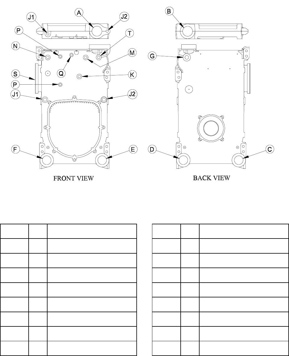
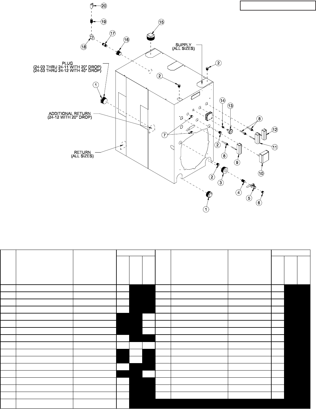
Figure 26a: Purpose of Tappings - Water Boilers
Tapping
Location
Size Water Boiler Tapping
Location
Size Water Boiler
(in) (in)
A 4 Supply J2 1 Plug
B 4 Plug K 3/4 Probe L.W.C.O.
C 3 Return M 3/4 Operating Temperature
Limit Control
D 3 Plug (24-03 thru 24-11)
Return (24-12) N 3/4 Hi Temperature
Limit Control/Manual Reset
E 3 Blow-Off / Drain Valve P 1/2 Plug
F 3 Plug Q 1/2 Temperature/Pressure Gauge
(Bush to 1/4")
G 1-1/2 Relief Valve S 3/4 Tankless Heater Control
J1 1 Plug T 3/4 Firing Rate Temperature Control
31
1 3" SQ. HD. PLUG 24-03 THRU 24-12 2 16 1-1/2" x 3/4" BLK BUSHING 24-03 THRU 24-07 1
1 3" SQ. HD. PLUG 24-12 WITH 20° DROP 1 16 1-1/2" x 1" BLK BUSHING 24-08 THRU 24-10 1
2 1" RECESSED HD PLUG ALL 4 16 1-1/2" x 1-1/4" BLK BUSHING 24-11 THRU 24-12 1
3 3" X 3/4" BLK BUSHING ALL 1 17 3/4" X 3" NIPPLE 24-03 THRU 24-07 1
4 3/4" CLOSE NIPPLE ALL 1 17 1" X 4" NIPPLE 24-08 THRU 24-10 1
5 3/4" BALL VALVE ALL 1 17 1-1/4" X 4" NIPPLE 24-11 THRU 24-12 1
6 3/4" SQ. HD. PLUG ALL 1 18 3/4" 90° ELBOW 24-03 THRU 24-07 1
7 1/2" RECESSED HD PLUG ALL 2 18 1" 90° ELBOW 24-08 THRU 24-10 1
8 3/4" LONG WELL ALL 1 1 1 18 1-1/4" 90° ELBOW 24-11 THRU 24-12 1
9 L4006E1109 CSD-1 EQUIPPED BOILERS 1 19 3/4" CLOSE NIPPLE 24-03 THRU 24-07 1
10 #550 PROBE LWCO CSD-1 EQUIPPED BOILERS 1 19 1" CLOSE NIPPLE 24-08 THRU 24-10 1
11 L4006A2015 ALL 1 19 1-1/4" CLOSE NIPPLE 24-11 THRU 24-12 1
12 FIRING RATE TEMP CTRL MODULATING BOILERS 1 20 RELIEF VALVE 10-408-05 24-03 THRU 24-04 1
13 TRIDICATOR GAUGE ALL 1 20 RELIEF VALVE 10-614-05 24-05 THRU 24-07 1
14 1/2" X 1/4" BLK BUSHING ALL 1 20 RELIEF VALVE 10-615-05 24-08 THRU 24-10 1
15 4" BK PLUG ALL 1 20 RELIEF VALVE 10-616-05 24-11 THRU 24-12 1
NOT
SHOWN 3/4" RECESSED HD. PLUG ALL 4
QUANTITY
KEY DESCRIPTION BOILER MODELS DESCRIPTION BOILER MODELS
QUANTITY
KEY
OPTIONAL
NOT
SUPPLIED
STANDARD
STANDARD
OPTIONAL
NOT
SUPPLIED
Figure 26b: Water Trim

32
WARNING
Failure to properly pipe boiler may result in
improper, unsafe system operation and void
manufacturer's warranty.
DO NOT improperly pipe boiler.
WARNING
All steam and hot water pipes must have
clearances of at least 1/2" from all
combustible construction.
I. WATER BOILERS - INSTALL WATER TRIM
Items for water trim are located in the water trim carton
(except for the separately ordered low water cutoff and
tankless heater control). Figures 26a and 26b show the
proper tappings for each item.
1. Install the temperature pressure gauge.
2. Install the low water cutoff (supplied by others).
Follow manufacturer’s instructions furnished with
control.
3. Install the immersion well and mount the aquastat
(limit control) onto the well.
4. Install the pressure relief valve as shown in Figure
40b. Relief valve must be installed in vertical
position.
5. Plug extra boiler tappings.
6. Install required bottom blowoff/drain valve
(supplied by others) per minimum piping
requirements for water boilers, see Figures 31, 32
and 33.
WARNING
Relief valve discharge piping must be piped
within six (6) inches of floor or to floor
drain to eliminate potential of severe burns.
Do not pipe in any area where freez ing
could occur. Do not install any shut-off
valves, plugs or caps in discharge piping.
J. BURNER INSTALLATION
Refer to burner manufacturer’s installation manual
for proper installation, fuel piping, wiring, burner
adjustment, burner start-up and service instructions.
Consult Section VI of this manual for burner
specifications and burner settings.
K. BOILER PIPING - HEATING APPLICATIONS
CONNECT SUPPLY AND RETURN PIPING TO
HEATING SYSTEM (see Figures 31, 32 and/or 33 for
water boilers and Figures 34 and 35 for steam boilers).

33
WARNING
Return water cannot be lower than 135°F for prolonged periods of time. Operation under these
conditions will result in sustained condensing within the combustion chamber and potentially
reduce boiler longevity.
In addition, the return water cannot be introduced into the boiler if it is more than 40°F less than
the idle boiler temperature. Continued operation under these conditions may result in
premature boiler failure through thermal shock.
Example
: A boiler that has been idle for some time since the last heat demand cycle may have
it's boiler water temperature reduced to 150°F. The return temperature from the next zone
activation cannot be less than 110°F.
If the above conditions exist, an RTC system must be installed to protect the boiler from
sustained condensing operation and thermal shock.
WARNING
A hot water boiler installed above radiation
level must be provided with a low water
cutoff device as part of the installation.
1. HOT WATER HEATING - This boiler must be
installed in strict accordance to the instructions
found in this installation manual. Deviations
from these installation instructions may void
manufacturer’s warranty. See warning below
to determine the use of the RTC. A Return
Temperature Control (RTC) may be provided to
protect the boiler from thermal shock and sustained
condensing operation. In addition, a properly
selected boiler circulator and diverting valve, along
with the return sensor, must be installed when using
the RTC. A number of typical Crown applications
have been added to the appendix (Appendix A).
Select the appropriate application before proceeding.
a. Parallel Piping Systems – An existing parallel
piping system may be used, provided the return
water is not below 135°F for prolonged periods
of time, and the return water temperature is
not more than 40°F less than the idle boiler
temperature (see warning below). A flow
analysis should be performed to determine the
flow through the boiler when the minimum (and
smallest) and maximum number of zones are
activated. A sufficient flow through the boiler
should be maintained to assure a maximum of
40°F difference between the boiler supply and
return.
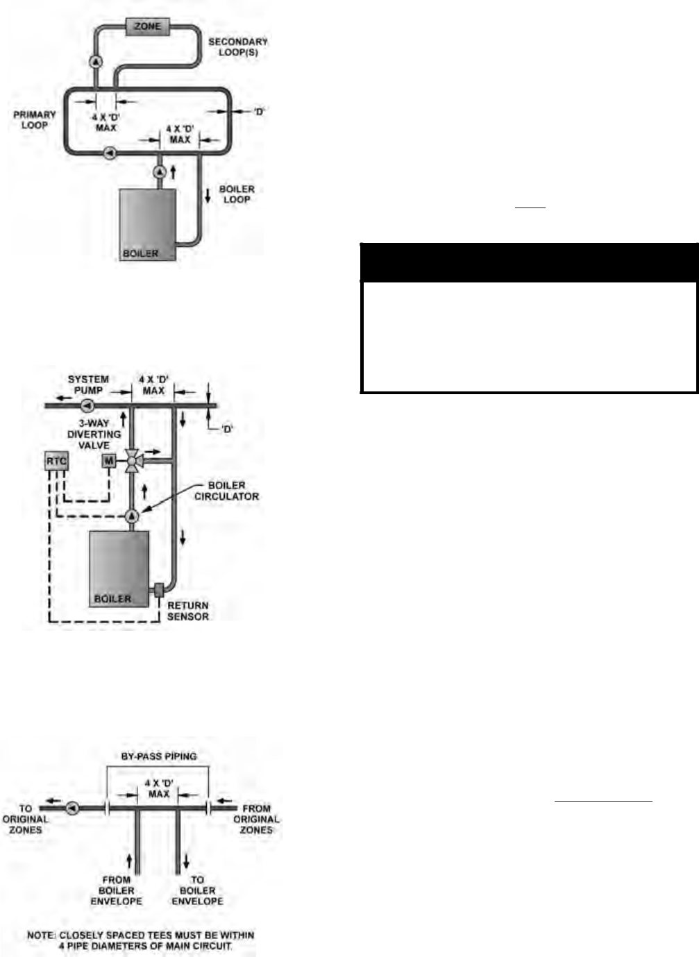
If the conditions above cannot be met, then
parallel piping systems must be converted to a
primary/secondary arrangement, de-coupling
the system pump from the boiler loop. The
system pump cannot influence the flow through
the boiler(s) in a primary/secondary piping
arrangement. The concept must be for the boiler
loop to inject heat into a primary loop, provided
the return water into the boiler is at least 135°F.
A by-pass containing two closely spaced tees
must be installed to de-couple the boiler loop
from the primary loop (see Figure 30). Care
must be taken to avoid dead heading the
system pump. Conversions should be reviewed
and approved by a Consulting Engineer or
other qualified professional to avoid system
deficiencies.
b. Primary/Secondary Piping – Boiler(s) must
be installed into a heating system that is
(are) designed as a primary/secondary piping
arrangement when the flow through the boiler
cannot be maintained to provide a 20°F - 40°F
difference between the boiler supply and
return. When using an RTC, the boiler loop
contains a boiler, boiler circulator and diverting
valve, along with the return temperature control
(RTC) and return sensor. The diverting valve
consists of a 3-way valve, positioned through
the use of an electronic actuator. The boiler loop
injects heat into the primary loop, provided the
temperature of the boiler return water is greater
than 135°F. If the temperature is below 135°F,
the diverting valve closes, recirculating the
boiler water until it has heated above the 135°F
minimum limit. The supply and return of the
boiler loop is connected to the primary loop
through the use of two closely spaced “Tees”, at
a maximum branch centerline distance of 4 times
the primary loop diameter (4 x D Max.) The
RTC provides a signal to the actuator based on
the absolute water temperature and the rate of
change in water temperature.
c. Multiple Boilers – Multiple boilers are installed
the same as single boiler installations. Each
boiler loop will contain it’s own boiler circulator,
diverting valve, RTC and return sensor (see
Appendix A). Commonly available sequencers
can be used in conjunction with the Return
Temperature Control by energizing the control’s
heat demand circuit. The outdoor reset feature
of the sequencer must be used in multiple
boiler installations. The outdoor reset feature
34
of the RTC cannot be used on multiple boiler
installations.
d. Boiler Circulator – The boiler circulator selection
will maintain a constant and minimum flow
through the boiler during every heat demand.
In addition, the circulator will maintain a flow
around the return sensor. The circulator must
be properly selected, based on the design
temperature between the boiler supply and
boiler return. Appendix B lists the appropriate
pumps for both 20 ºF and 40 ºF applications. A
boiler circulator must be used with and without
an RTC System for a primary/secondary piping
arrangement.
WARNING
If the boiler circulator you have selected is
greater than 1/3 HP, an isolation relay must
be added when using the RTC.
If a 3-phase boiler circulator has been
selected than a properly sized motor starter
must be installed when using the RTC.
e. Diverting Valve – A diverting 3-way valve must
be part of the boiler loop for boiler protection to
be active when using the RTC. Only a Crown
approved valve and actuator may be used for
boiler protection. The valve sizing does change
based on the designed boiler ∆T, since the flow
rate and the pressure drop change for each. See
Appendix B for proper valve selection.
f. Glycol Antifreeze Solutions - Many systems
today use ethylene or propylene glycol antifreeze
solutions as a measure for freeze protection, as
well as a pump lubricator and corrosion inhibitor.
The properties of the glycol mixture have an
impact on valve and pump sizing. All glycol
solutions have a lower specific heat than water.
This means that the glycol solution cannot
transfer heat as well as pure water, resulting in
the need for higher flow rates. In addition, the
viscosity of the glycol solution is usually higher
than water, requiring a higher pump head for the
same given flow. Consult factory for specific
applications, pump selection and flow rate.
g. Nipple and Sensor - The 3 x 12 special nipple
must be installed in the lower right return
connection when looking at the rear section,
when using the RTC. Insert the return sensor
using pipe dope.
2. STEAM HEATING, consult I=B=R Installation
and Piping Guide No. 200. For piping details, see
Figure 34. Figure 35 shows a typical pumped return/
boiler feed unit arrangement. Figure 36 illustrates
the required mounting elevations for McDonnell and
Miller 150 and 63 float low water cut-offs.
Figure 28:
Typical Crown Boiler Loop w/3-way Diverting
Valve, Where System Return may be Less than
135°F.
Figure 30: Parallel Piping Conversion
Figure 27:
Typical Crown Boiler - Primary - Secondary Loop
System (Return Temps always Greater than 135°F.)
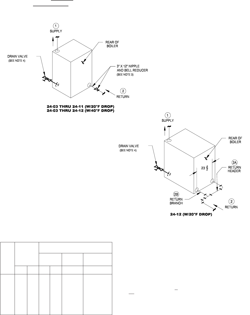
35
Recommendation 1 — Use when:
• system return water is not less than 135° F for prolonged periods of time
• system flow does not impact flow through the boiler
Figure 31: Series 24 Minimum Piping Recommendation 1 - Water Boiler
NOTES:
1. All piping is schedule 40.
2. Pipe sizes listed are based on a 20°F or 40°F differential (temperature drop).
Select one to match application.
3. When specified return piping size is less than 3”, install 3” X 12” nipple and appropriate
size bell reducer directly into boiler return tapping as shown.
4. Drain valve — ball valve preferable, gate valve acceptable alternative
(supplied by others).
- Minimum valve size per ASME code is 3/4” NPT.
LEDOM
YLPPUS
GNIPIP
)NI(EZIS
)1(
)NI(EZISGNIPIPNRUTER
)2(NRUTER
NRUTER
REDAEH
)A2(
NRUTER
HCNARB
)B2(EZIS).YTQ(
F°02
PORD
F°04
PORD
F°02
PORD
F°04
PORD
F°02
PORD
F°02
PORD
30-42
40-42
50-42
60-42
70-42
80-42
90-42
01-42
11-42
21-42
2
2
2
2/1-2
2/1-2
2/1-2
3
3
3
4
2/1-1
2/1-1
2/1-1
2/1-1
2
2
2
2/1-2
2/1-2
2/1-2
2
2
2
2/1-2
2/1-2
2/1-2
3
3
3
4
2/1-1
2/1-1
2/1-1
2/1-1
2
2
2
2/1-2
2/1-2
2/1-2
—
—
—
—
—
—
—
—
—
3
—
—
—
—
—
—
—
—
—
3)2(
Pipe Sizing and Notes
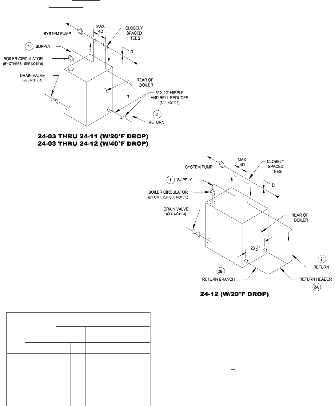
36
Figure 32: Series 24 Minimum Piping Recommendation 2 - Water Boiler
Recommendation 2 — Use when:
• system return water is not less than 135° F for prolonged periods of time
• system flow does impact flow through the boiler(ie. zoning, mixing)
NOTES:
1. All piping is schedule 40.
2. Pipe sizes listed are based on a 20°F or 40°F differential (temperature drop).
Select one to match application.
3. When specified return piping size is less than 3”, install 3” X 12” nipple and appropriate
size bell reducer directly into boiler return tapping as shown.
4. Drain valve — ball valve preferable, gate valve acceptable alternative
(supplied by others).
- Minimum valve size per ASME code is 3/4” NPT
5. Proper boiler circulator sizing is listed in Appendix B.
Pipe Sizing and Notes
LEDOM
YLPPUS
GNIPIP
)NI(EZIS
)1(
)NI(EZISGNIPIPNRUTER
)2(NRUTER
NRUTER
REDAEH
)A2(
NRUTER
HCNARB
)B2(EZIS).YTQ(
F°02
PORD
F°04
PORD
F°02
PORD
F°04
PORD
F°02
PORD
F°02
PORD
30-42
40-42
50-42
60-42
70-42
80-42
90-42
01-42
11-42
21-42
2
2
2
2/1-2
2/1-2
2/1-2
3
3
3
4
2/1-1
2/1-1
2/1-1
2/1-1
2
2
2
2/1-2
2/1-2
2/1-2
2
2
2
2/1-2
2/1-2
2/1-2
3
3
3
4
2/1-1
2/1-1
2/1-1
2/1-1
2
2
2
2/1-2
2/1-2
2/1-2
—
—
—
—
—
—
—
—
—
3
—
—
—
—
—
—
—
—
—
3)2(
Figure 33: Series 24 Minimum Piping Recommendation 3 - Water Boiler
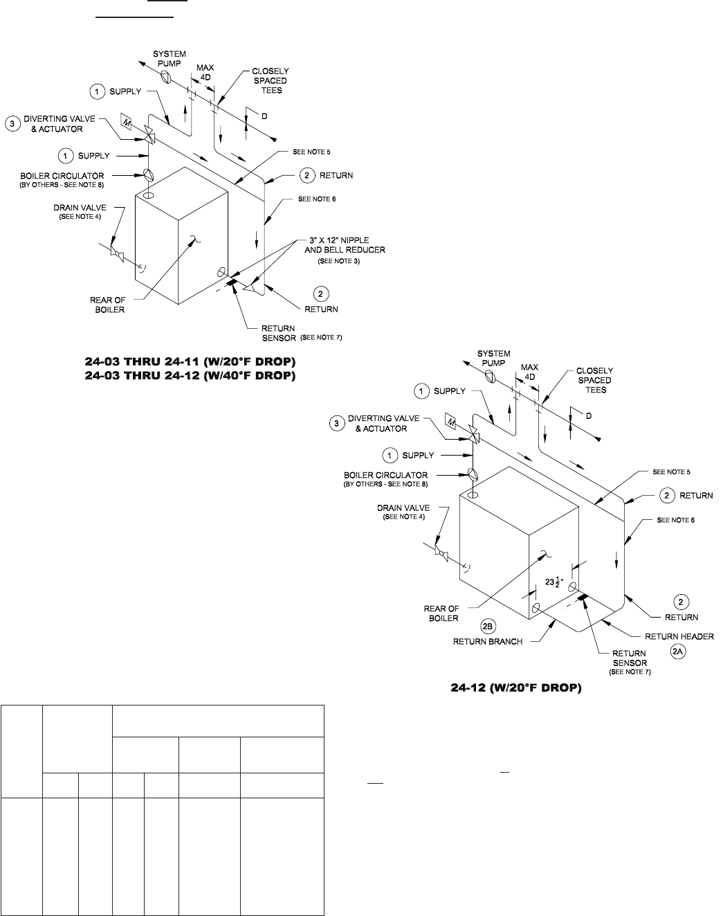
37
Figure 32: Series 24 Minimum Piping Recommendation 2 - Water Boiler Figure 33: Series 24 Minimum Piping Recommendation 3 - Water Boiler
Recommendation 3 — Use when:
• system return water is less than 135° F for prolonged periods of time
• system flow does impact flow through the boiler(ie. zoning, mixing)
• requires addition of RTC Return Temperature Control and accessories
NOTES:
1. All piping is schedule 40.
2. Pipe sizes listed are based on a 20°F or 40°F differential (temperature drop).
Select one to match application.
3. When specified return piping size is less than 3”, install 3” X 12” nipple and appropriate
size bell reducer directly into boiler return tapping as shown.
4. Drain valve — ball valve preferable, gate valve acceptable alternative
(supplied by others).
- Minimum valve size per ASME code is 3/4” NPT
5. Maximum linear feet of pipe from 3-way bypass port to sensor location = 11 feet.
Bypass line shall be the same diameter as return Á
6.
Minimum linear feet of pipe from point of mixing (where bypass meets return line) to
sensor location = 4 feet.
7. Install special 3” x 12” nipple with 1/4” NPT side tapping closest to boiler. Where
applicable, use bell reducer to adapt to recommended return pipe size.
8. Proper boiler circulator sizing is listed in Appendix B.
Pipe Sizing and Notes
LEDOM
YLPPUS
GNIPIP
)NI(EZIS
)1(
)NI(EZISGNIPIPNRUTER
)2(NRUTER
NRUTER
REDAEH
)A2(
NRUTER
HCNARB
)B2(EZIS).YTQ(
F°02
PORD
F°04
PORD
F°02
PORD
F°04
PORD
F°02
PORD
F°02
PORD
30-42
40-42
50-42
60-42
70-42
80-42
90-42
01-42
11-42
21-42
2
2
2
2/1-2
2/1-2
2/1-2
3
3
3
4
2/1-1
2/1-1
2/1-1
2/1-1
2
2
2
2/1-2
2/1-2
2/1-2
2
2
2
2/1-2
2/1-2
2/1-2
3
3
3
4
2/1-1
2/1-1
2/1-1
2/1-1
2
2
2
2/1-2
2/1-2
2/1-2
—
—
—
—
—
—
—
—
—
3
—
—
—
—
—
—
—
—
—
3)2(

38
NOTICE
When possible, domestic hot water production should utilize a dedicated boiler(s). This will
allow the other boiler(s) to be shut down and isolated during the summer months. If the boiler
load is shared between heating and domestic hot water, then one needs to determine if a hot
water priority is required. If a priority is not selected, erratic domestic hot water production may
result during the beginning and end of every heating season. Conversely, a priority for domestic
hot water production may cause a significant heating z one activation delay, in an improperly
balanced system. Parallel piping conversions may require isolation from the heating system to
prevent system flow influence on DHW performance. Consult a qualified system heating
professional to design for the proper application.
1. Hot Water Boiler/Indirect Water Heater – The use
of indirect water heaters for domestic hot water
generation is common. Consider prioritizing the
generation of domestic hot water using an indirect
water heater (See notice below).
a. Dedicated Boiler for DHW Production – If the
boiler(s) is (are) dedicated to production of
domestic hot water production, the diverting
valve is not necessary. (see Appendix A.11 for
details) However, the RTC should be used,
along with a boiler circulation loop that includes
a boiler circulator and return sensor. The boiler
circulator and piping must be sized to circulate
at a minimum, the flow rate required for a 40 ºF
∆T application. See Appendix B for circulator
details. The circulator for the domestic hot water
system is separate from the boiler circulator.
GNINRAW
tsumpooLdroftraHdetcurtsnocylreporpA
maetsnruterytivargllanodellatsnieb
noderiuqertonsipooLdroftraH.smetsys
.smetsysnruterdepmup
L. BOILER PIPING, DOMESTIC HOT WATER
(DHW) APPLICATION – This section of the manual
identifies the boiler piping details when domestic hot
water is required. The two methods described for
domestic hot water production are through the use of
an indirect hot water heater or tankless coils. If a shell
and tube or plate heat exchanger is desired, follow
the instructions for the indirect water heater. Always
consult the heat exchanger manufacturer for specific
instructions and limitations.
NOTICE
DO NOT use the boiler circulator as an
indirect domestic hot water system
circulator.
b. Shared Boiler for DHW Production – If the
boiler(s) is(are) shared between the heating
system and the production of domestic hot
water, the diverting valve and all of the RTC
components should be used. The piping
arrangement is different between a system
that utilizes the outdoor reset feature vs. one
that doesn’t. See Appendix A for various
applications. If the outdoor reset feature of
the RTC is used, the domestic hot water piping
is part of the boiler loop, independent of the
diverting valve. Although this bypasses the
protection devices of the RTC system, the
volume and temperature conditions of a DHW
system presents no deleterious impact on
the boiler. This prevents a reset system loop
temperature from affecting DHW production.
Multiple boiler applications, utilizing an indirect
water heater arrangement, require the use of
a sequencer and connection to the indirect
water heater as a load on the secondary loop.
An outdoor reset function for multiple boiler
applications with DHW, require a DHW priority
or reset override. Consult your sequencer
manufacturer for recommendations.
2. Hot Water Boiler/Tankless Coil – Tankless coils,
mounted into the side of boilers, have been
used successfully for many years. Tankless
coils may still be used in single and multiple
boiler applications. (See Appendix A for typical
applications.)
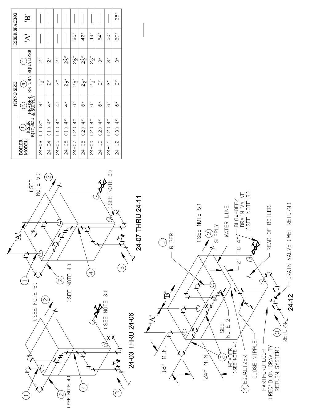
39
Figure 34: Minimum Piping Requirements For Gravity Return Series 24 Steam Boilers
NOTES:
1. All piping is schedule 40.
2. To prevent condensate from being trapped in header, do not reduce
equalizer elbow at header connection.
3. Ball valve preferable, gate valve acceptable alternative
(supplied by others).
• Minimum valve size per ASME code is 3/4” NPT 24-03/24-04;
1” NPT 24-05/24-08; 1-1/4” NPT 24-09/24-12.
• Increasing the valve size will improve the blowdown operation.
• In all cases, piping connecting blowoff valve to boiler shall be full
size to the point of discharge.
4. Header piping may be run over top of the boiler if space does not
allow for piping arrangement shown. Increased service
requirements will result however.
5. Supply from the boiler header must be connected between the first
boiler riser and the header drip (or Hartford Loop). Do not connect
supply between risers or opposite end of boiler header.
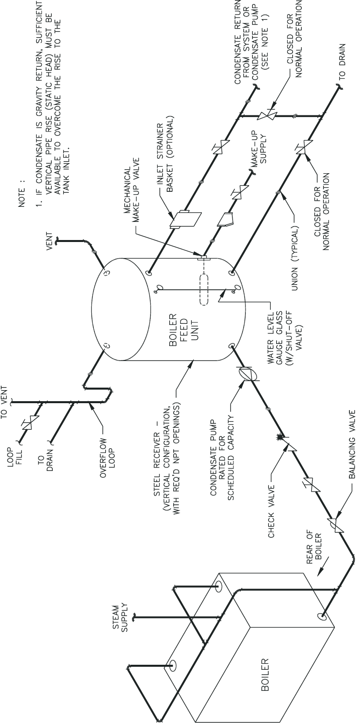
40
Figure 35: Typical Steam Piping Arrangement for Boilers with Pumped Condensate Return and Boiler Feed Unit
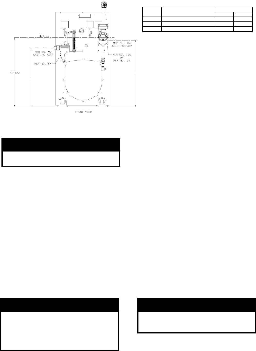
41
M. CONNECT TANKLESS HEATER PIPING as
shown in Figure 38. See Table IV for Tankless Heater
Ratings.
1. Install Flow Regulator
If flow through the heater is greater than its rating,
the supply of adequate hot water may not be able to
keep up with the demand. For this reason a FLOW
REGULATOR matching the heater rating should be
installed in the cold water line to the heater. Refer
to Figure 36 for piping recommendations. Locate
the flow regulator below the inlet (cold water side)
of the heater and a minimum of 36” away from the
inlet so that the regulator is not subjected to excess
temperatures during “off” periods when it is possible
for heat to be conducted back through the supply
line. The flow regulator will limit the flow of supply
water regardless of inlet pressure variations ranging
from 20 to 125 psi.
2. Install Water Temperature Mixing Valve
Refer to Figure 38 for piping recommendations.
Adjust and maintain the mixing valve in accordance
with manufacturer’s instructions.
Installation of a mixing valve will also lengthen the
delivery of the available hot water by mixing some
cold water with the hot. In addition, savings of hot
water will be achieved since the user will not waste
as much hot water while seeking desired water
temperature. Higher temperature hot water required
by dishwashers and automatic washers is possible
by piping the hot water from the heater prior to
entering the mixing valve. An electric hot water
booster can also be used. The mixing valve should
be “trapped” by installing it below the cold water
inlet to heater to prevent lime formation in the valve.
3. Flushing of Heater
All water contains some sediment which settles
on the inside of the coil. Consequently, the heater
should be periodically backwashed. This is
accomplished by installing hose bibs as illustrated
in Figure 38 and allowing water at city pressure to
run into hose bib A, through the heater, and out hose
bib B until the discharge is clear. The tees in which
the hose bibs are located should be the same size as
heater connections to minimize pressure drop.
4. Hard Water
A water analysis is necessary to determine the
hardness of your potable water. This is applicable
to some city water and particularly to well water.
An appropriate water softener should be installed
based on the analysis and dealer’s recommendation.
This is not only beneficial to the tankless heater but
to piping and fixtures plus the many other benefits
derived from soft water.
NOTICE
The following guidelines should be followed
when piping the tankless heater:
WARNING
Install a mixing valve at the tankless heater
outlet to avoid risk of burns or scalding
due to excessively hot water at fixtures.
Do not operate the boiler when equipped
with a tankless heater unless mixing valve
is operating properly.
CAUTION
Do not operate tankless heater with hard
water. Tankless failure will result. Install
water softener if hard water is present.
Figure 36:
Mounting Elevations
of M&M 150, 64 and 67
Float Low Water Cut-offs.
"A" "B"
67 35-1/2" -
64 - 37-1/2"
150 - 40"
Primary or Secondary
Primary (Gravity Return)
Primary (Pumped Return)
Cut-Off Height
ApplicationL.W.C.O.
“A”
“B”
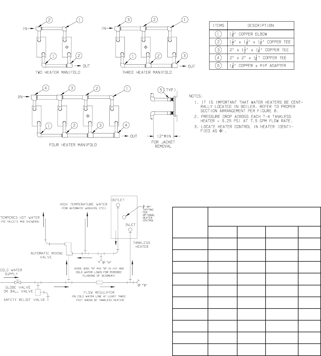
42
Figure 37: Minimum Piping Requirements for Series 24 Tankless Heater Manifolds
Figure 38: Schematic Tankless Heater Piping
sgnitaRretaeHsselknaTVIelbaT
relioB
ledoM
sretaeHsselknaT4-TforebmuN
dellatsnI
1 2 3 4
30-42 57.6 --- --- ---
40-42 5.7 --- --- ---
50-42 5.7 --- --- ---
60-42 5.7 51 --- ---
70-42 5.7 51 --- ---
80-42 5.7 51 --- ---
90-42 5.7 51 5.22 ---
01-42 5.7 51 5.22 ---
11-42 5.7 51 5.22 ---
21-42 5.7 51 5.22 03
Notes:
1. Ratings are given in gallons per minute continuous
flow of water heated from 40°F to 140°F with 200°F
boiler water.
2. For tankless heater quantities less than maximum
allowable, it is important that water heaters be
centrally located in the boiler.
See Figure 8 for appropriate locations.
3. Tankless heater pressure drop is 5.5 PSI at
7.5 GPM.
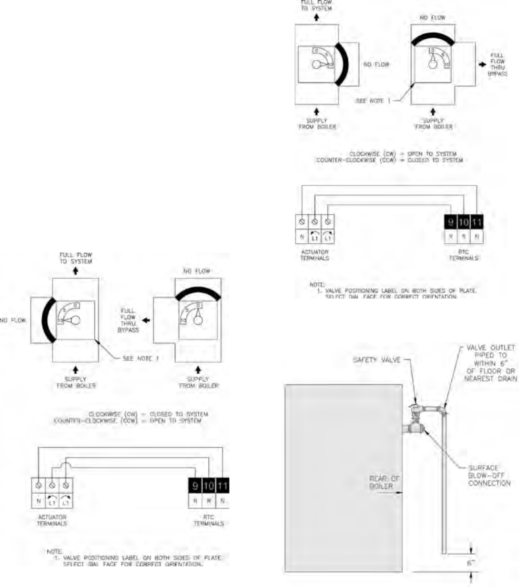
43
Figure 40a: Steam Boiler - Safety Valve Hook-Up
Figure 39b: Diverting Valve/Actuator Wiring
(CW - Open to System)
Figure 39a: Diverting Valve/Actuator Wiring
(CCW - Open to System)
N. ELECTRIC WIRING - Install all field wiring in
accordance with the National Electric Code and Local
Regulations.
Control voltage and/or 3-phase line voltage must
be supplied to the burner panel box through a fused
disconnect.
When using the RTC, a separate fused control circuit
shall feed the control to allow the exercising of the
valve actuator and boiler circulator during dormant
boiler operation.
Review electrical schematics in Appendix A and Burner
Electrical Diagram for more information.
O. RETURN TEMPERATURE CONTROL AND
COMPONENTS
1. Valve Actuator – The valve actuator is mounted to
the top of the diverting valve. Mount and connect
the actuator as illustrated in Appendix C. The
electrical connections depend on valve orientation.
Use Figures 39a and 39b as a guide.
2. Return Sensor – A sensor has been included with
the Return Temperature Control. The sensor must
be mounted for proper operation. The sensor is
mounted in the 3 inch NPT x 12 inch special return
nipple. The sensor must be inserted into the ¼ NPT
connection using pipe dope. The 3” nipple must be
inserted with the sensor closest to the boiler, using
the rear lower right connection. (Orientation based
on viewing the boiler from the rear.) The sensor
shall be connected to the RTC through a junction
box located above the nipple. Use grommets and
conduit to protect the leads and connection back to
the RTC controller.
3. Knock Down Boiler Installations – The installation
instructions above must be followed for all
knockdown boilers as well. The controller is
mounted on the front jacket panel at the top right.
See Figures 41 and 42 for general component
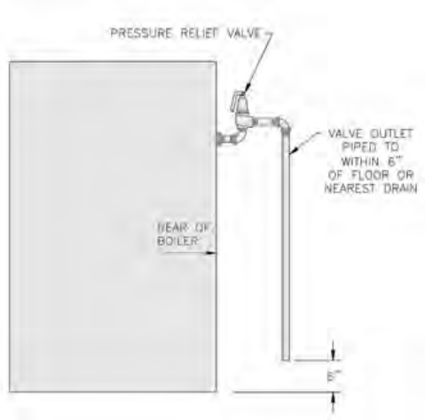
44
Figure 40b: Water Boiler - Pressure Relief Valve
Hook-Up
placement. The 14 gauge mounting bracket must
be attached to the jacket first using four (4) #8 x ¾”
drill point sheet metal screws.
One may find it easier to install some of the conduit
connectors with their corresponding conduit runs onto
the RTC back panel before mounting to the bracket.
The actual controller can and should be removed from
the back panel during the mounting process. This
will eliminate the potential for accidental damage to
the controller. The RTC back panel is mounted onto
the bracket with (4) #8-32 x ½” type F, Phillips Pan
head screws supplied with the controller. The middle
3 rear knockouts should be used before utilizing the 5
knockouts exiting the bottom of the control. Depending
on the final configuration, most of the controller
connections could be used. Typically, the return sensor,
actuator control and boiler pump exit the rear of the
controller.
Wire the RTC controller to the various components
as shown below. The “Mix” and “Outdoor” sensor
are optional and must be connected if outdoor reset
function is desired. The outdoor reset function on
this controller cannot be used in a multiple boiler
application. A boiler sequencer must be used when an
outdoor reset feature is required in a multiple boiler
application.
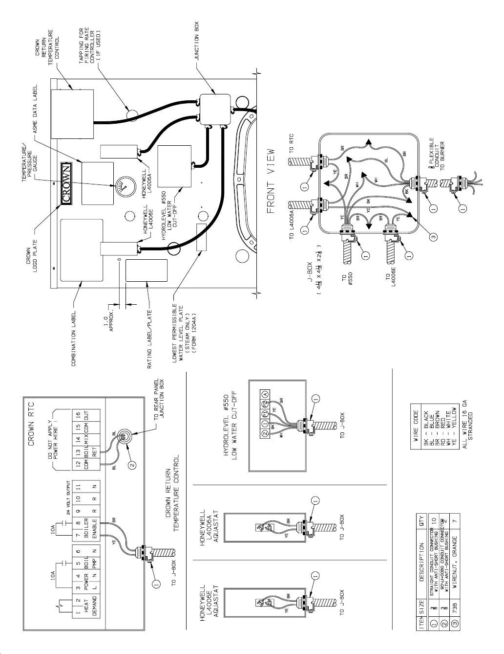
45
Figure 41: Typical Boiler Wiring with RTC (Front)
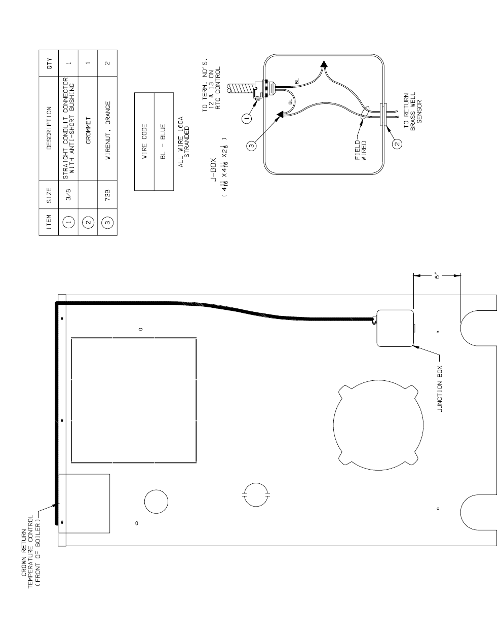
46
Figure 42: Typical Boiler with RTC Return Sensor (Rear)

47
SECTION IV - OPERATING INSTRUCTIONS
A. ALWAYS INSPECT INSTALLATION BEFORE
STARTING BURNER.
B. FILL HEATING SYSTEM WITH WATER.
Boiler must be cleaned and fully free of oil and dirt.
CLEAN HEATING SYSTEM IF boiler water or
condensate return water is dirty or if erratic water lines
or surging exist after a few days of boiler operation.
Refer to step (K) for proper cleaning instructions for
steam and water boilers.
1. STEAM BOILERS - Fill boiler to normal water
line. As shown in Figure 1, the normal water line
is 41½” from the floor or bottom of casting. At
the start of each heating season and once or twice
during the season try SAFETY VALVE to be sure it
is in working condition. To do this, fasten wire or
cord to lever of valve and pull lever — standing safe
distance away from valve.
2. HOT WATER BOILERS - Fill entire Heating
System with water and vent air from system. Use
the following procedure on a Series Loop or Multi-
zoned System to remove air from system when
filling:
a. Close isolation valve in boiler supply piping.
b. Isolate all circuits by closing zone valves or
balancing valves.
c. Attach a hose to bib cock located just below
isolation valve in boiler supply piping.
(Note - Terminate hose in five gallon bucket at a
suitable floor drain or outdoor area).
d. Starting with one circuit, open zone valve.
e. Open bib cock.
f. Open fill valve (Make-up water line should be
located directly above isolation valve in boiler
supply piping).
g. Allow water to overflow from bucket until
discharge from hose is bubble free for 30
seconds.
h. Open zone valve to the second zone to be
purged, then close the first. Repeat this step until
all zones have been purged, but always have one
zone open. At completion, open all zone valves.
i. Close bib cock, continue filling the system until
the pressure gauge registers normal system
design operating pressure. Close fill valve.
(Note - If make-up water line is equipped
with pressure reducing valve, system will
automatically fill to normal system design
operating pressure. Leave globe valve open.)
j. Open isolation valve in boiler supply piping.
k. Remove hose from bib cock.
C. SET CONTROLS with burner service switch turned
“OFF”.
1. PRESS RESET BUTTON on primary control and
release.
2. On STEAM BOILERS set cut-in pressure on
L404A Pressuretrol for three (3) PSI and differential
pressure for two (2) PSI. These pressures may be
varied to suit individual requirements of installation.
3. On STEAM BOILERS WITH TANKLESS
DOMESTIC WATER HEATERS, set boiler water
temperature dial on low limit operating control at
190°F (max.). Set differential at 10°.
4. ON WATER BOILERS WITHOUT TANKLESS
HEATERS, set high limit dial on L4006A at 210°F.
This temperature may be varied to suit requirements
WARNING
If you do not follow these instructions
exactly, a fire or explosion may result
causing property damage or personal
injury.
If any unusual or improper operation or
site conditions are observed, turn the
boiler off and contact an experienced
and skilled service agency.
Follow component manufacturer’s
instructions. Component manufacturer’s
instructions were provided with the
boiler. Contact component manufacturer
for replacement if instructions are
missing. Do not install, start up, operate,
maintain or service this boiler without
reading and understanding all of the
component instructions. Do not allow
the boiler to operate with altered,
disconnected or jumpered components.
Only use replacement components
identical to those originally supplied with
the boiler and burner.
CAUTION
Failure to clean the system will result in
erratic water lines and surging, and other
improper system operations.
DANGER
Do not operate boiler with pressure
above maximum allowable working
pressure listed on the Boiler Rating
Label.
DO NOT draw water from boiler while in
use. When adding water while boiler is
in operation, do not open supply valve
fully but add water slowly.

48
of installation.
5. ON WATER BOILERS WITH TANKLESS
HEATERS, set low limit operating control dial at
190°F and high limit dial 210°F. Operating control
must be a minimum of 20° below high limit setting.
Set differential at 25°.
D. ADJUST BURNER according to the Burner Manual.
1. FLAME FAILURE
The Series 24 boiler controls operate the burner
automatically. If for unknown reasons the burner
ceases to fire and the reset button on the primary
control is tripped, the burner has experienced
ignition failure. Before pressing the reset button,
call your serviceman immediately.
WARNING
Do not attempt to start the burner when
excess oil or gas has accumulated in the
combustion chamber, when the unit is full
of vapor, or when the combustion chamber
is very hot.
E. RETURN TEMPERATURE CONTROL: Initial
Set-Up and Operation – The return temperature
control (RTC) is an important part of the overall boiler
system. The primary function of the RTC is to protect
the boiler from thermal shock and sustained flue gas
condensation. The RTC monitors the temperature of
the water returning into the boiler through a return
sensor. The RTC controls the 3-way diverting valve
mounted on the supply of the boiler to prevent return
water less than 135º F from entering the boiler. The
boiler circulator provides constant and minimum flow
through the boiler during every heat demand. Prior
to the start of any boiler cycle, the diverting valve is
closed to a full by-pass condition, forcing 100% boiler
water re-circulation. The diverting valve opens and
will continue to open provided the return sensor is
satisfied. Conversely, large temperature drops will
close the diverting valve to a position as to prevent
low temperature return water. The RTC along with
the ancillary components must be properly installed
as identified in Section III, if there is any possibility
of system return water temperature less than 135°F. A
detailed description of the controller and it’s features
can be found in the RTC Installation and Maintenance
Manual.
1. Initial Start-up - Upon initial start-up, the control
will be energized, identifying the control name and
revision on the LED display. If wired properly, the
control should be energized at all times. The RTC
circuit should be supplied from a different source
than the burner or boiler circuit. The RTC control
should be energized at all times.
2. Testing – The RTC should be tested on initial start-
up, as well as during any troubleshooting exercise.
Depressing the test button will activate a test
sequence and energize the red test light on the front
of the control. Each of the controllers outputs and
relays will be energized and tested. One may pause
the test sequence at any time by depressing the test
button. See the RTC Installation & Maintenance
Manual for a detailed description of the sequence
and the potential error messages.
a. Return Sensor - The return sensor must be
properly connected or an error message will be
displayed. Both a short and an open circuit in
the sensor circuit will cause an error message to
be displayed and the valve will be moved to a
partially open position until the error is resolved.
b. Valve Actuator – During the valve actuator test
sequence, confirm that the valve travels through
90 degrees of rotation from a full closed position
to a full open position. The pointer on the shaft
must rotate from “10” to “0” respectively.
3. Adjust Setpoints – The RTC must have a number of
setpoints adjusted for proper operation. Below is
a summary, however see the RTC Installation and
Maintenance Manual for more details. To activate
the ADJUST menu, simultaneously depress and
hold the Item, and buttons. ADJUST will
appear in the upper right hand corner of the LED
display.
a. ROOM - Set desired room temperature. This
will provide parallel shift to heating curve.
OUTDR DESIGN OFF
b. MIX TARGET – This represents a fixed target
supply temperature when the outdoor reset
feature in NOT selected. (OUTDR DESIGN =
OFF) Set the MIX TARGET temperature to the
designed boiler supply temperature. Example:
If the boiler loop is designed to supply hot water
to the system at 180ºF, set the MIX TARGET
to 180ºF. This is also the same as the operating
aquastat set point. The mix target is adjustable
from 60°F to 200ºF. The default setting is 180°F.
NOTE: This function is only for applications
where the mix sensor is installed.
c. MIX DSGN – Mix design temperature represents
the design heating system supply temperature
when the outdoor reset feature is selected.
(OUTDR DESIGN = ON) This represents the
design of the system loop. If unsure of the
original design temperature, set the MIX DSGN
to the same temperature as the boiler operating
aquastat, typically 180ºF. The MIX DSGN is
adjustable from 70°F to 210ºF. The default
setting is 180°F.
d. OUTDR DSGN – The outdoor design
temperature represents the value used in the
heat loss calculations, when the outdoor reset
feature is selected. (OUTDR DESIGN = ON) If
this value is unknown, use the value found in

49
ASHRAE Fundamentals for the area closest to
the installation. This value has a default of 10°F,
and is adjustable between –60ºF to 32ºF.
e. WWSD – The Warm Weather Shut Down feature
is used only when the outdoor reset feature
is selected. (OUTDR DESIGN = ON) If the
outdoor temperature rises above the WWSD
value, WWSD will be displayed. If a demand
for heat is generated when the control is in the
WWSD mode, the boiler will be disabled. The
default for the WWSD is 70ºF, but is adjustable
from 35ºF to 100ºF.
f. MIX MIN – This represents the minimum mix
target supply temperature when the outdoor reset
feature is selected. (OUTDR DESIGN = ON)
This is the lowest temperature the controller is
allowed to use as a MIX TARGET temperature.
During mild conditions, if the RTC calculates a
MIX TARGET below the MIX MIN, the target
will be adjusted to match the MIX MIN setting.
g. MIX MAX – This represents the highest
temperature allowed as the MIX TARGET
temperature when the outdoor reset feature is
selected. (OUTDR DESIGN = ON) If the RTC
calculates a MIX TARGET higher than the MIX
MAX, the MIX TARGET will take the value of
the MIX MAX. Typically, this is set between
200ºF and 220ºF. The temperature must be set
below the lowest permissible temperature for
any system related component affected by boiler
supply water.
h. OPEN DELAY – This value represents the
number of seconds required for the actuator to
open through 90 degrees of rotation. Leave in
default value of 50 seconds.
i. BOIL MIN – This is the minimum boiler return
temperature allowed. The minimum value has
been set to 135ºF, adjustable to as high as 230ºF.
The RTC will control the diverting valve while
maintaining a minimum BOIL MIN temperature.
Setting should remain at 135ºF unless a higher
minimum boiler temperature is required.
j. BOIL MIN DELAY – This represents the time
(in seconds) required for warm-up during an
initial cold start. This prevents the counter
from including cold start warm up time in the
total boiler operation time below 135ºF. This
grace period is provided for every heat demand
cycle until 135ºF has been sensed at the return
sensor. Once the return sensor has sensed a
return temperature reading of 135ºF, after the
heat demand cycle has initiated, the grace period
is terminated. The warm up time includes a 90
seconds of pre-purge time. Use the values in
Table V for the correct application.
k. PUMP DELAY – Pump delay represents the
time (in seconds) for pump purge (boiler
relioB
ledoM
YALEDNIMLIOB
)sdnoceS(
30-42 045
40-42 064
50-42 014
60-42 073
70-42 063
80-42 043
90-42 023
01-42 013
11-42 003
21-42 092
circulator purge) after a heat demand cycle. This
minimizes the amount of boiler temperature
overshoot at the end of a boiler cycle. During
the pump purge the diverting valve will
continue to operate and prevent low return water
temperatures from entering the boiler. At the
end of the pump purge period the diverting valve
will be immediately closed. The default PUMP
DELAY is set to 30 seconds.
l. UNITS – The temperature units can be changed
to either Fahrenheit or Celsius. The default
temperature unit is Fahrenheit.
4. ERROR MESSAGES – Error messages are shown
on the LED display. The function in error will be
shown as a black background label in the LED.
Most of the errors indicate an open or short circuit,
connected to the RTC. The RTC Installation and
Maintenance Manual identifies common errors.
Cycle through the error messages and repair as
required.
a. Return Sensor Error – If the return water
temperature sensor has been damaged or omitted,
the BOIL item will be displayed as either a
“short” or “open” circuit. This will force the
mixing device (i.e. 3-way valve) to run at a
fixed 30% open position. The system may not
receive enough heat nor will it be fully protected,
however a significant change will be obvious to
occupants and/or operators.
b. Operation Below Minimum – If the return sensor
has been damaged or omitted, and the return
water is allowed to return to the boiler below
135ºF, the BOIL MIN field will be displayed
along with ERR. The failure must be identified
and repaired immediately since the boiler
has been operating in a condition that fosters
premature boiler failure.
5. COMPONENT EXERCISE - The RTC will exercise
Table V: Boil Min Delay Settings

50
J. TEST CONTROLS
WARNING
Before installation of the boiler is
considered complete, the operation of the
boiler controls should be checked,
particularly the low water cutoff and the
high limit control.
All controls must be checked prior to putting the boiler
in service.
1. CHECK OPERATING CONTROL OPERATION.
Raise and lower operating control setting as required
to start and stop burner.
2. CHECK OPERATION OF HIGH LIMIT
CONTROL —
Jumper Operating Control Terminals. Allow burner
to operate until shutdown by limit. Installation is
not considered complete until this check has been
made. REMOVE JUMPER.
3. CHECK LOW WATER CUTOFF control with water
level at normal water line (see Figure 1). Raise
operating control setting to allow burner to operate.
Open boiler drain to allow water level to drop to
bottom of sight glass until burner operation is shut
down by low water cutoff.
Close boiler drain and refill to normal water line.
Burner should automatically restart during fill.
RESET OPERATING CONTROL.
both the boiler circulator and the diverting valve
during periods of dormant activity provided power
is supplied to the control.
F. DIVERTING VALVE ACTUATOR - A 3-way
diverting valve is used to control the temperature of
the water returning to the boiler. Proper operation
is required to protect the boiler from thermal shock
and sustained condensate production. Confirm the
operation of the valve as shown above. See Figures 39a
and 39b.
G. BOILER OPERATING AQUASTAT – The operating
aquastat, L4006A, can be found on the front of the
boiler, to the right of the temperature/pressure gauge.
The operating aquastat should be set to the designed
supply temperature, typically 180ºF. The operating
aquastat set point, the RTC MIX TARGET or the RTC
MIX DESGN, should be set to the same value for
20°F ∆T applications. In 40°F ∆T applications, the
operating aquastat (L4006A) must be set 20°F higher
than the MIX TARGET and MIX DESIGN . Under
no circumstances should the operating aquastat be set
below 135ºF plus (+) the designed boiler temperature
drop, ∆T (ºF).
Example: if the flow rate through the boiler
corresponds to a 20ºF ∆T design, the operating
aquastat cannot be set lower than 135 + 20 = 155ºF.
In reality, most systems are designed for a 180ºF supply
water and 160ºF return water. The accuracy of the
operating aquastat is less than the RTC accuracy, often
requiring the operating aquastat temperature to be
bumped upward a few degrees.
H. BOILER HIGH LIMIT AQUASTAT – If used, the
high limit aquastat, L4006E, can be found on the front
of the boiler, to the left of the temperature/pressure
gauge. The high limit aquastat can be identified with a
red manual reset button. Ideally, the high limit aquastat
should be set 10 -15°F above the RTC MIX MAX
setting, when the outdoor reset feature is selected.
Typically, this is set between 200ºF and 220ºF. The
temperature must be set below the lowest permissible
temperature for any system related component affected
by boiler supply water. Under no circumstances can the
high limit aquastat be set higher than 250ºF.
I. BOILER MODULATING CONTROL – Various
controls are used to modulate burner firing rates.
No attempt will be made to cover every possibility,
however a general outline will be given.
Most modulation controls require the entry of a
boiler temperature identifying boiler operation at the
maximum firing rate. A boiler operating temperature
below that will also generate a full firing rate. When a
boiler heat demand is generated the unit will initiate at
either a low or high fire rate and quickly ramp up to the
high fire rate. The unit will continue to fire at the high
fire rate until the boiler high fire modulating limit is
reached.
Many modulation controls require the entry of a burner
off or low fire setting. The burner will modulate
between the high fire and low fire rate based on the
absolute boiler temperature as well as the rate of change
in boiler temperature.
If using a T991 Proportional Control or a similar
modulating device in a traditional hydronic system,
the minimum setting shall be the sum of the designed
heating system return temperature + boiler ∆T + 10°F.
Example: System Supply 180°F
System Return 160°F
System ∆T 20°F
Boiler ∆T 40°F
Min. Setting = 160°F + 40°F + 10°F
= 210°F
*NOTE: A higher flow through the boiler, achieving
a 20°F ∆T would lower the minimum to 190°F.
If using the same control in a system where the
designed return is less than 135°F, then the minimum
becomes:
135°F + Boiler ∆T + 10°F

51
sufficiently to permit a steady trickle of water
from the surface blowoff pipe. Continue this
slow boiling and trickle of overflow for several
hours until the water coming from the overflow
is clear.
d. Stop burner and drain boiler in a manner and to
a location that hot water can be discharged with
safety.
e. Refill boiler to normal water line. If water in
gauge glass does not appear to be clear, repeat
steps (a. thru e.), and boil out the boiler for a
longer time.
2. Low pressure steam boilers such as the Series
24 should be maintained with appropriate water
treatment compounds. After cleaning process has
been completed, add water treatment compounds
as recommended by your local qualified water
treatment company.
3. Remove temporary surface blowoff piping and
replug tapping. Boil or bring water temperature to
180°F promptly in order to drive off the dissolved
gases in the fresh water.
4. If unsteady water line, foaming or priming persist,
install gate valve in Hartford Loop and drain valves
in return main and at boiler and proceed as follows:
a. Connect hoses from drain cocks to floor drain.
Close gate valve in Hartford Loop and open
drain cock in return main. Fill boiler to normal
water level, turn on burner and operate boiler
at this water level for at least 30 minutes after
the condensate begins to run hot, then turn off
burner.
Close all radiator valves. Remove all supply
main air valves and plug the openings in supply
main.
b. Draw about 5 gallons of hot water from boiler
into a container and dissolve into it appropriate
amount of a recommended boilout compound.
Remove surface blowoff plug and pour this
solution into boiler, then reinstall plug.
c. Turn on burner and keep operating while feeding
water to boiler slowly. This will raise water level
in boiler slowly so that water will be boiling hot
and will rise slowly into supply main and back
through return main, flowing from drain hose
at about 180°F. Continue until water runs clear
from drain hose for at least 30 minutes.
d. Stop feeding water to boiler but continue
operating burner until excess water in boiler
flows out through supply main and water lowers
(by steaming) until it reaches normal level in
boiler. Turn off burner. Drain boiler. Open all
radiator valves. Reinstall all supply main air
valves. Open gate valve in Hartford Loop.
e. When boiler has cooled down sufficiently (crown
sheet of sections are not too hot to touch), close
CAUTION
Probe and float type low water cutoff
devices require annual inspection and
maintenance.
4. CHECK OPERATING CONTROL on boiler
equipped with tankless heaters. With burner off,
draw hot water until burner starts, then turn off hot
water and check burner shutdown.
5. CHECK RTC CONTROL - see the Test Section in
the RTC Installation and Maintenance Manual.
K. BOILER AND SYSTEM CLEANING - STEAM
BOILER
NOTICE
A qualified water treatment chemical
specialist should be consulted for
recommendations regarding appropriate
chemical compounds and concentrations
which are compatible with local
environmental regulations.
WARNING
Chemicals used in treating boiler water are
toxic and/or harmful. Always use protective
clothing and equipment when working
with/near chemicals. Contact local
authorities to determine if treated boiler
water can be discharged into local waste
water system.
1. Oil, greases & sediments which accumulate in a
new boiler and piping must be removed in order
to prevent an unsteady water line and carry over
of the water into the supply main above boiler.
Operate the boiler with steam in the entire system
for a few days allowing the condensate to return
to the boiler. If the condensate can temporarily be
wasted, operate boiler only for the length of time
it takes for condensate to run clear. If the latter
cannot be achieved or if the condensate is returned
to the boiler, boil out the boiler using the SURFACE
BLOWOFF connection. See Figure 40a.
a. Drain boiler until water is just visible in gauge
glass. Run temporarily 1½” pipe line from the
surface blowoff connection to an open drain or
some other location where hot water may be
discharged safely. Do not install valve in this
line.
b. Add an appropriate amount of recommended
boilout compounds.
c. Start burner and operate sufficiently to boil
the water without producing steam pressure.
Boil for about 5 hours. Open boiler feed pipe
52
the drain cocks at boiler and in return main and
feed water slowly up to normal level in boiler.
Turn on burner and allow boiler to steam for
10 minutes then turn off burner. Draw off one
quart of water from bottom gauge glass fitting
and discard. Draw off another quart sample and
if this sample is not clear, repeat the cycle of
draining the boiler and return main and refilling
the boiler until sample is clear.
f. If the boiler water becomes dirty again at a later
date due to additional sediment loosened up in
the piping, close gate valve in Hartford Loop,
open drain cock in return main, turn on burner
and allow condensate to flow to drain until it has
run clear for at least 30 minutes while feeding
water to boiler so as to maintain normal water
level. Turn off burner, drain boiler, open gate
valve in Hartford Loop, then repeat step (1)
above.
5. Make pH or Alkalinity Test.
After boiler and system have been cleaned and
refilled as previously described, test the pH of the
water in the system. This can easily be done by
drawing a small sample of boiler water and testing
hydrion paper which is used in the same manner
as litmus paper, except it gives specific readings.
A color chart on the side of the small hydrion
dispenser gives the reading in pH. Hydrion paper
is inexpensive and obtainable from any chemical
supply house or through your local druggist. The
pH should be higher than 7, but lower than 11. Add
some appropriate water treatment chemicals, if
necessary to bring the pH within the specified range.
6. Boiler is now ready to be put into service.
L. BOILER AND SYSTEM CLEANING - WATER
BOILERS
1. Filling of Boiler and System --- General --- In a hot
water heating system, the boiler and entire system
(other than the expansion tank) must be full of water
for satisfactory operation. Water should be added to
the system until the boiler pressure gauge registers
normal system design operating pressure. To insure
that the system is full, water should come out of all
air vents when opened.
2. Boiling Out of Boiler and System. The oil and
grease which accumulate in a new hot water boiler
can be washed out in the following manner.
a. Remove safety relief valve using extreme care to
avoid damaging it.
b. Add an appropriate amount of recommended
boilout compound.
c. Reinstall safety relief valve.
d. Fill the entire system with water.
e. Start firing the boiler.
f. Circulate the water through the entire system.
g. Vent the system, including the radiation.
h. Allow boiler water to reach operating
temperature, if possible.
i. Continue to circulate the water for a few hours.
j. Stop firing the boiler.
k. Drain the system in a manner and to a location
that hot water can be discharged with safety.
l. Remove plugs from all available returns and
wash the water side of the boiler as thoroughly as
possible, using a high-pressure water stream.
m. Refill the system with fresh water.
3. Add appropriate boiler water treatment compounds
as recommended by your local qualified water
treatment company.
4. Make pH or Alkalinity Test.
After boiler and system have been cleaned and
refilled as previously described, test the pH of
the water in the system. This can easily be done
by drawing a small sample of boiler water and
testing with hydrion paper which is used in the
same manner as litmus paper, except it gives
specific readings. A color chart on the side of the
small hydrion dispenser gives the reading in pH.
Hydrion paper is inexpensive and obtainable from
any chemical supply house or through your local
druggist. The pH should be higher than 7 but lower
than 11. Add some appropriate water treatment
chemicals, if necessary to bring the pH within the
specified range. With this lower level of protection,
care must be exercised to eliminate all of the free
oxygen in the system.
5. Boiler is now ready to be put into service.

53
TNATROPMI
SITI,NOITAREPOLAMRONGNIRUD,FI
REPRETAWEROMDDAOTYRASSECEN
TLUSNOC,WOLEBDETACIDNINAHTHTNOM
OTNAICINHCETECIVRESDEIFILAUQA
.SKAELROFMETSYSRUOYKCEHC
:NOITIDDARETAWEVISSECXE
)htnoM/laG(
½6130-42
2240-42
½7250-42
3360-42
½8370-42
4480-42
½9490-42
5501-42
½0611-42
6621-42
M. FREQUENT WATER ADDITION
A leaky system will increase the volume of make-up
water supplied to the boiler which can significantly
shorten the life of the boiler. Entrained in make-up
water are dissolved minerals and oxygen. When the
fresh, cool make-up water is heated in the boiler, the
minerals fall out as sediment and the oxygen escapes
as a gas. Both can result in reduced boiler life. The
accumulation of sediment can eventually isolate
the water from contacting the cast iron. When this
happens the cast iron in that area gets extremely hot
and eventually cracks. The presence of free oxygen
in the boiler creates a corrosive atmosphere which, if
the concentration becomes high enough, can corrode
the cast iron through from the inside. Since neither of
these failure types are the result of a casting defect, the
warranty does not apply. The maintenance of system
integrity is the best method to prevent these types of
failure.
N. OXYGEN CORROSION:
GNINRAW
retawreliobehtfonoitanimatnocnegyxO
reliobleetsdnanorifonoisorrocesuaclliw
.eruliafreliobotdaelnacdna,stnenopmoc
revoctonseodytnarrawdradnatss'nworC
noitanimatnocnegyxoybdesuacsmelborp
pu-dliub)emil(elacsroretawreliobfo
.retawfonoitiddatneuqerfybdesuac
There are many possible causes of oxygen
contamination such as:
a. Addition of excessive make-up water as a result
of system leaks.
b. Absorption through open tanks and fittings.
c. Oxygen permeable materials in the distribution
system.
In order to insure long product life, oxygen sources
must be eliminated. This can be accomplished by
taking the following measures:
a. Repairing system leaks to eliminate the need for
addition of make-up water.
b. Eliminating open tanks from the system.
c. Eliminating and/or repairing fittings which allow
oxygen absorption.
d. Use of non-permeable materials in the
distribution system.
e. Consult your local water treatment specialist for
specific recommendations.

54
2. CLEAN THE BOILER FLUEWAYS
a. Remove the jacket left side panels.
b. Loosen nuts securing the flue cleanout plates
and remove the plates. The insulation should
be removed with the plates taking care not to
damage the insulation.
c. Using a 1¼” diameter wire or fibre bristle brush
(36” handle) clean the flueways. Start at the top
of each flueway opening and work down the pin
rows using two or three horizontal strokes per
row for best results.
3. CLEAN TOP OF BOILER SECTIONS
Remove the jacket top panel. Remove the top flue
canopy cover or outlet assembly. Use a flashlight to
inspect the upper portion of the flueways and top of
castings for soot and debris. Heavy accumulations
over 1/16” thick must be removed. Remove the
canopy being careful not to damage the cerafelt
strips. Brush and vacuum the upper flueways and
tops of castings.
4. CLEAN THE FIREBOX
a. Disconnect fuel line(s) and remove burner and
burner mounting plate.
A. GENERAL — Inspection should be conducted
annually. Service as frequently as specified in
paragraphs below. While service or maintenance is
being done, electrical power to the boiler must be “off”.
B. CLEAN THE BOILER HEATING
SURFACES & FLUE at least once each year,
preferably at the end of the heating season.
1. CLEAN THE VENT SYSTEM — Vent system
should be checked annually for:
a. Obstructions.
b. Accumulations of soot.
c. Deterioration of vent pipe or vent accessories
due to condensation or other reasons.
d. Proper support — no sags, particularly in
horizontal runs.
e. Tightness of joints.
f. Remove the smoke pipe. Remove all
accumulations of soot with wire brush and
vacuum. Remove all obstructions. Replace all
deteriorated parts and support properly. Seal all
joints.
SECTION V - SERVICE INSTRUCTIONS
WARNING
This boiler must only be serviced and repaired by skilled and experienced service
technicians.
If any controls are replaced, they must be replaced with identical models.
Read, understand and follow all the instructions and warnings contained in all the sections
of this manual.
If any electrical wires are disconnected during service, clearly label the wires and assure
that the wires are reconnected properly.
NEVER operate boiler without all sight glasses and brackets in place and securely fastened
and sealed. Very HOT combustion gas may cause burn injury.
Read, understand and follow all the instructions and warnings contained in ALL of the
component instruction manuals.
Assure that all safety and operating controls and components are operating properly before
placing the boiler back in service.
DANGER
This boiler uses flammable gas, high voltage electricity, moving parts, and very hot water
under high pressure. Assure that all gas and electric power supplies are off and that the
water temperature is cool before attempting any disassembly or service.
More than one gas shut-off valve and electrical disconnect switch are used on the boiler.
Assure that all gas valves and electrical disconnect switches are off before attempting any
disassembly or service.
Do not attempt any service work if gas is present in the air in the vicinity of the boiler.
Never modify, remove or tamper with any control device.

55
b. Using wire or fibre bristle brush clean crown of
boiler and inside of water legs.
c. Inspect target wall (903A only) for damage or
deterioration. If target wall is damaged, replace.
5. REASSEMBLE BOILER
CAUTION
Do not start the burner unless canopy,
smokepipe, burner mounting plate and all
flue plates are secured in place.
a. If removed, install the canopy taking care to
align the cerafelt strips. If strips are damaged
replace as needed.
b. Reinstall burner mounting plate to front section
making sure 3/16” diameter rope gasket is in
place and forms gas tight seal. If gasket is
damaged, replace.
c. Bolt burner to burner mounting plate. Inspect
gasket to assure adequate seal. Replace if
damaged. Connect oil line(s) and/or gas line(s).
d. Reinstall flue plates making sure gasket on each
plate is in place and forms gas tight seal. If
damaged, all edges of the cleanout plates should
be sealed with Silastic sealant when reinstalled
until insulation can be replaced.
e. If removed, reinstall jacket top.
f. Reinstall left side panels.
g. Reinstall smokepipe.
C. MAINTENANCE OF LOW WATER CUTOFF
DEVICES.
NOTICE
Probe and float type low water cutoff
devices require annual inspection and
maintenance.
1. PROBE TYPE LOW WATER CUTOFF
Although these devices are solid state in their
operation, the probe is exposed to possible
contamination in the boiler water and subject to
fouling.
It is important to physically remove the probe from
the boiler tapping annually and inspect that probe
for accumulation of scale or sediment.
Follow these steps to inspect, clean and/or replace
the probe:
a. Turn off electric service to the boiler.
b. Drain boiler water to a level below the tapping
for the probe.
c. Disconnect wiring connections between the low
water cutoff control and the probe.
d. Dismount the low water cutoff control from the
probe.
DANGER
Assure that the boiler is at z ero pressure
before removing the LWCO probe. Do not
rely on the pressure gauge to indicate that
the boiler is at zero pressure. Open the
safety valve to relieve all internal pressure
prior to proceeding. Safety valve discharge
piping must be piped such that the potential
for burns is eliminated.
e. Unscrew the probe from the boiler tapping.
f. Inspect that portion of the probe that is exposed
to the boiler water for a scale or sediment
buildup.
g. Light deposits may be removed by wiping the
probe with a damp cloth. Wiping the probe
with a cloth soaked in vinegar will remove more
tenacious lime deposits. The most stubborn
deposits may be removed from the probe by
using a diluted amount (three 3 parts of water to
one (1) part) of phosphoric acid (H2PO4).
WARNING
Exercise caution when handling phosphoric
acid and follow the instructions on
container label. Always use protective
clothing and equipment when working
with/near chemicals.
h. Wire brushing of the probe is not recommended
as the soft platinum guard ring sandwiched
between the ceramic insulators may be damaged.
Care must be taken not to damage this ring in
any way or the useful life of the probe may be
shortened.
i. Clean the pipe threads of the probe to remove
old, hardened pipe dope and other foreign matter.
j. Apply a moderate amount of good quality pipe
dope to the pipe threads on the probe. Leaving
the two end threads bare. Do not use PTFE
(Teflon) tape.
k. Screw the probe into the boiler tapping.
l. Mount the low water cutoff control on the probe.
m. Reconnect the control to probe wiring.
n. Fill the boiler to its normal waterline.
o. Add boiler water treatment compound as needed.
p. Restore electric service to the boiler.
q. Fire burner to bring the water in the boiler to a
boil to drive off free oxygen.
r. BEFORE RETURNING BOILER TO
SERVICE Follow the low water cutoff checkout
procedure on Pages 46 and 47.

56
2. FLOAT TYPE LOW WATER CUTOFF
During the heating season, if an external low water
cutoff is on the boiler, the blow off valve should
be opened once a month (use greater frequency
where conditions warrant) to flush out the sediment
chamber so the device will be free to function
properly.
Low water cutoffs and water feeders should be
dismantled annually by qualified personnel, to the
extent necessary to insure freedom from obstructions
and proper functioning of the working parts. Inspect
connecting lines to boiler for accumulation of
mud, scale, etc., and clean as required. Examine
all visible wiring for brittle or worn insulation and
make sure electrical contacts are clean and that they
function properly. Give special attention to solder
joints on bellows and float when this type of control
is used. Check float for evidence of collapse and
check mercury bulb (where applicable) for mercury
separation or discoloration. DO NOT ATTEMPT
TO REPAIR MECHANISMS IN THE FIELD.
Complete replacement mechanisms, including
necessary gaskets and installation instructions, are
available from the manufacturer.
D. CHECK BURNER AND CONTROLS at least once
a year. See Section IV - Operating Instructions, Step J
for control checks. See Burner Manual for burner tests
and adjustments.
E. LUBRICATE BOILER COMPONENTS according
to manufacturer’s instructions. Generally, this involves
the oil burner and circulator. This includes the type of
lubricant to use, frequency of lubrication, and points to
lubricate.
F. GENERAL MAINTENANCE CONSIDERATIONS
1. Keep radiators and convectors clean.
2. If a hot water radiator is hot at the bottom but not at
the top, it indicates that air has accumulated inside
and should be vented. To vent radiator, hold small
cup under air vent (located near top of radiator),
open vent until water escapes and then close.
3. If much water is added to system, it is advisable to
heat system to a high temperature and vent again.
This will make less venting necessary during the
winter.
4. Where an expansion tank is used, make sure that
neither the tank nor its drain pipe is exposed to
freezing temperatures. Never place valves in piping
leading to or from expansion tank.
5. Boiler and system cleaning will help assure
trouble free operation. See Section IV - Operating
Instructions, Steps K or L for procedure.
G. ATTENTION TO BOILER WHILE NOT IN
OPERATION
WARNING
If boiler is not used during winter time, it
must be fully drained to prevent freeze
damage.
1. Spray inside surfaces with light lubricating or
crankcase oil using gun with extended stem so as to
reach all corners.
2. With steam boilers, at end of season add sufficient
water to fill boiler to top of water column and leave
it that way until fall when water should be drained
again to proper level. If at this time boiler water is
dirty, drain water, flush out boiler, and refill with
clean water to prescribed water level.
3. Always keep the manual fuel supply valve shut off
when the burner is shut down for an extended period
of time.
4. To recondition the heating system in the fall season
after a prolonged shut down, follow the instructions
outlined in Section IV - Operating Instructions,
Steps B through L.
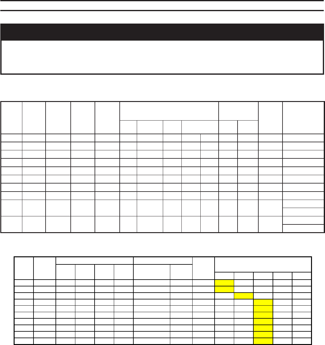
57
Table VI: Beckett Burner Specifications
SECTION VI - BURNER SPECIFICATIONS
ECITON
,serusserppmup,srenrubgniwollofehtnopudesaberaseiticapacdnasgnitarreliob42seireS
lanoitiddarofrenrubhtiwdehsinrufsnoitcurtsniotrefeR.serusserpdlofinamdnaseziselzzon
ecivres,stnemtsujdarenrub,sliatedgniriw,gnipipleuf,noitallatsnireporpgnidragernoitamrofni
.pu-tratsrenrubdnasnoitcurtsni
RELIOB
LEDOM
RENRUB
TUPNI
)HPG(
RENRUB
.RFM
RENRUB
LEDOM
EBUTRIA
.BMOC
SGNITTESRENRUB .SSERPPMUP
)ISP( ELZZON
EKAM
ATADELZZON
DAEH RIA
RETTUHS
RIA
DNAB
REPMADRIA
HGIHWOL
WOL
ERIF
HGIH
ERIF
XHPG
EPYT-ELGNA
30-42 1.3 TTEKCEB 005-FC KK06FC 2 01 3 A/N A/N --- 051 OGAH P-°54X05.2
40-42 2.4 TTEKCEB 008-FC HK08FC 1 8 0 A/N A/N --- 051 OGAH P-°54X05.3
50-42 6.5 TTEKCEB 008-FC HK08FC 2 01 6 A
/N A/N --- 051 OGAH P-°54X05.4
60-42 0.7 TTEKCEB 0041-FC DK66FC 3 A/N A/N 57.2 0.4 051 003 OGAH P-°06X00.4
70-42 3.8 TTEKCEB 0041-FC DK66FC 4 A/N A/N 0.3 5.6 051 572 OGAH P-°54X00.5
80-42 6.9 TTEKCEB 0041-FC EEK66FC 1 A/N A/N 5.3 5.8 051 003 OGAH P-°54X05.5
90-42 6.11 TTEKCEB A0032-FC GK66FC 0 A/N A/N 0.2 0.4 0
51 572 OGAH P-°54X00.7
01-42 2.31 TTEKCEB A0032-FC GK66FC 1 A/N A/N 0.2 0.6 051 572 OGAH P-°54X00.8
11-42 8.41 TTEKCEB 0052-FC PK66FC 0 A/N A/N 5.0 0.3 572 572 OGAH
P-°54X05.4)L(
P-°54X05.4)H(
21-42 4.61 TTEKCEB 0052-FC PK66FC 0 A/N A/N 5.0 0.4 5
72 572 OGAH
P-°54X00.5)L(
P-°54X00.5)H(
Boiler
Model
Gas
Burner
Model
Damper Settings Manifold Pressure ("WC)
Rate
Control
Minimum Inlet Pressure "WC1
Low Fire High
Fire Shutter Band Low Fire
(Start) High Fire By Gas Train Pipe Size
1" 1 1/4" 1 1/2" 2" 2 1/2"
24-03 CG10.1S 10 1 (1.3) 2.5 On/Off 3.24 3.13 -- -- --
24-04 CG10.4S 5 2 (1.3) 2.6 On/Off 3.64 3.4 -- -- --
24-05 CG10.5S 7 1 (1) 3.3 On/Off 4.61 4.26 -- -- --
24-06 CG10.6S 10 6 (1.1) 3.64 On/Off 5.43 4.76 4.38 -- --
24-07 CG15.3S 18 43 0.9 3.1 Lo/Hi/Lo 5.31 4.44 3.99 -- --
24-08 CG15.4S 21 63 0.95 3.3 Lo/Hi/Lo 6.14 4.9 4.41 -- --
24-09 CG25.2S 23 47 0.8 3.43 Lo/Hi/Lo -- 4.69 4.28 3.86 --
24-10 CG25.3S 26 52 0.8 3.44 Lo/Hi/Lo -- -- 4.94 4.4 3.98
24-11 CG25.4S 28 58 0.8 3.0 Lo/Hi/Lo -- -- 4.88 4.21 3.68
24-12 CG50.2S 10 25 0.8 2.1 Lo/Hi/Lo -- -- 3.87 3.56 2.94
1. Standard burners are indicated with bold numbering in shaded boxes. The other burners shown are optional.
OIL BURNERS
GAS BURNERS (Natural Gas)

58
SECTION VII - REPAIR PARTS & CARTON CONTENTS
The following parts may be obtained from any Crown distributor. To find the closest Crown distributor,
consult the area Crown representative or the factory at:
Crown Boiler Co.
Customer Service
P.O. Box 14818
Philadelphia, PA 19134
www.crownboiler.com

59
SERIES 24 MASTER PARTS LIST
DESCRIPTION
SECTIONS
SECTION
JOINER
CARTON
REAR FLUE OUTLET
CARTON
FLAME OBS. CARTON
WATER TRIM CARTON
STEAM TRIM CARTON
TARGET WALL CARTON
BURNER
MTG PLATE
CARTON
BURNER ADAPTER PLATE
CARTON
BUNRER CARTON
CANOPY CARTON
JACKET CARTON
OIL BOILER CARTON
GAS BOILER CARTON
FRONT (KEY # 1)
BACK (KEY # 5)
CENTER 1 (KEY # 2)
"CX" (KEY # 4)
F G H 7 8 10 12 8" 4"
CROWN PART # OR
QUANTITY.
330000
330001
330002
330003
331200
331201
331202
330133
330134
330135
330136
330050
331210
331220
330025
330408
330404
1 EA.
1 EA.
1 EA. 1 EA. 1 EA. 1 EA.
WATER
24-03W 1 1 1 1 1 1 1 1 1
SEE FIGURE 23 FOR APPROPRIATE CROWN PN
SEE SECTION VI FOR BURNER SPECIFICATIONS
330123 330203 331001 331101
24-04W 1 1 2 1 1 1 1 1 330124 330204 331002 331102
24-05W 1 1 3 1 1 1 1 1 330125 330205 331003 331103
24-06W 1 1 4 1 1 1 1 1 1 330126 330206 331004 331104
24-07W 1 1 5 2 1 1 1 1 330127 330207 331005 331105
24-08W 1 1 6 1 1 1 1 1 1 330128 330208 331006 331106
24-09W 1 1 7 2 1 1 1 1 330129 330209 331007 331107
24-10W 1 1 8 3 1 1 1 1 330130 330210 331008 331108
24-11W 1 1 9 2 1 1 1 1 1 330131 330211 331009 331109
24-12W 1 1 10 1 2 1 1 1 1 330132 330212 331010 331110
STEAM
24-03S 1 1 1 1 1 1 1 1 1 330123 330203 331011 331111
24-04S 1 1 2 1 1 1 1 1 330124 330204 331012 331112
24-05S 1 1 3 1 1 1 1 1 330125 330205 331013 331113
24-06S 1 1 4 1 1 1 1 1 1 330126 330206 331014 331114
24-07S 1 1 5 2 1 1 1 1 330127 330207 331015 331115
24-08S 1 1 6 1 1 1 1 1 1 330128 330208 331016 331116
24-09S 1 1 7 2 1 1 1 1 330129 330209 331017 331117
24-10S 1 1 8 3 1 1 1 1 330130 330210 331018 331118
24-11S 1 1 9 2 1 1 1 1 1 330131 330211 331019 331119
24-12S 1 1 9 1 1 2 1 1 1 1 330132 330212 331020 331120
1) NOTE: IF TANKLESS HEATERS (*PN 330020) ARE USED, REPLACE ONE INTERMEDIATE SECTION WITH COIL SECTION (*PN 330004, KEY # 3) FOR EACH
TANKLESS HEATER USED. SEE FIGURE 1 FOR MAX. NUMBER OF PERMITTED TANKLESS HEATERS
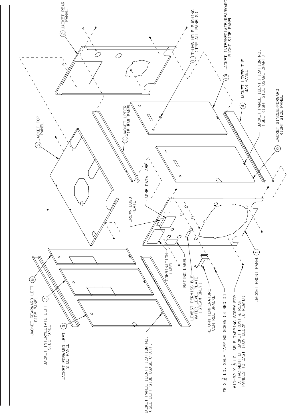
60
Figure 43: Series 24 Jacket Assembly (Boiler Models 24-03 thru 24-12)
SECTION VII - REPAIR PARTS (Continued)

61
CROWN CARTON PART #
330203
330204
330205
330206
330207
330208
330209
330210
330211
330212
24-03
24-04
24-05
24-06
24-07
24-08
24-09
24-10
24-11
24-12
1 FRONT JACKET PANEL 330310 1 1 1 1 1 1 1 1 1 1
2 REAR JACKET PANEL 330320 1 1 1 1 1 1 1 1 1 1
UPPER TIE BAR ASSY, 3 SEC. 330333 2
UPPER TIE BAR ASSY, 4 SEC. 330334 2
UPPER TIE BAR ASSY, 5 SEC. 330335 2
UPPER TIE BAR ASSY, 6 SEC. 330336 2
UPPER TIE BAR ASSY, 7 SEC. 330337 2
UPPER TIE BAR ASSY, 8 SEC. 330338 2
UPPER TIE BAR ASSY, 9 SEC. 330339 2
UPPER TIE BAR ASSY, 10 SEC. 330340 2
UPPER TIE BAR ASSY, 11 SEC. 330341 2
UPPER TIE BAR ASSY, 12 SEC. 330342 2
LOWER TIE BAR ASSY, 3 SEC. 330343 2
LOWER TIE BAR ASSY, 4 SEC. 330344 2
LOWER TIE BAR ASSY, 5 SEC. 330345 2
LOWER TIE BAR ASSY, 6 SEC. 330346 2
LOWER TIE BAR ASSY, 7 SEC. 330347 2
LOWER TIE BAR ASSY, 8 SEC. 330348 2
LOWER TIE BAR ASSY, 9 SEC. 330349 2
LOWER TIE BAR ASSY, 10 SEC. 330350 2
LOWER TIE BAR ASSY, 11 SEC. 330351 2
LOWER TIE BAR ASSY, 12 SEC. 330352 2
TOP PANEL, 3 SEC. 330323 1
TOP PANEL, 4 SEC. 330324 1
TOP PANEL, 5 SEC. 330325 1
TOP PANEL, 6 SEC. 330326 1
TOP PANEL, 7 SEC. 330327 1
TOP PANEL, 8 SEC. 330328 1
TOP PANEL, 9 SEC. 330329 1
TOP PANEL, 10 SEC. 330330 1
TOP PANEL, 11 SEC. 330331 1
TOP PANEL, 12 SEC. 330332 1
LEFT SIDE PANEL, L5 330370 1 1 1 1
LEFT SIDE PANEL, L10 330371 1 1 1 1 1 1 1 1 1 1
LEFT SIDE PANEL, L11 330372 1 1 1
LEFT SIDE PANEL, L17 330373 1 1 1
LEFT SIDE PANEL, L18 330374 1 1 1 2 2 2 3
RIGHT SIDE PANEL, R15 330360 1 1
RIGHT SIDE PANEL, R21 330361 1 1 1
RIGHT SIDE PANEL, R24 330362 1 1 1 2
RIGHT SIDE PANEL, R27 330363 1 1 1
RIGHT SIDE PANEL, R30 330364 1 1
RIGHT SIDE PANEL, R33 330365 1 1
11 THUMB HOLE BUSHING 330390 3 4 4 5 6 7 8 8 8 11
- 10-32 X 1/2 SELF TAP MACH SCREW 9 9 9 9 9 9 9 9 9 9
- #8 X 3/4 SHEET METAL SCREW 34 34 34 34 34 34 34 34 34 34
5
6
7
8
9
10
JACKET CARTON
KEY
3
4
CROWN
PART #
QUANTITY
DESCRIPTION
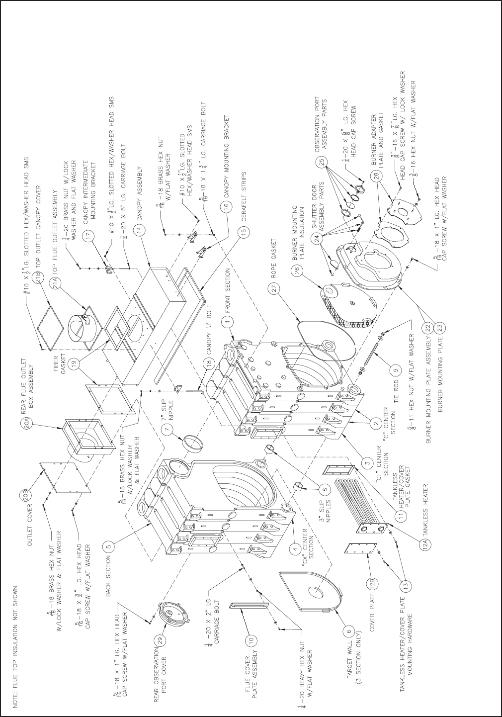
62
Figure 44: Bare Boiler Assembly

63
"F" "G" "H"
7 7" PUSHNIPPLE 310005 2 3 4
8 3" PUSHNIPPLE 310006 4 6 8
9 5/8 X 9 3/4 TIE ROD 900310 8 12 16
5/8 HEAVY HEX NUT (GRADE 9) 900307 16 24 32
5/8 HI-STRENGTH FLAT WASHER 900308 16 24 32
LOCTITE # 592, 50 ml TUBE 900350 1 2 2
GASKET ROPE, 3/8 DIA x 96" 330033 2 ft 3 ft 4 ft
ROPE ADHESIVE 330032 1 1 1
SIL-BOND, RTV 6500, 10.3 OZ TUBE 900046 2 3 3
10 FLUE CLEANOUT COVER ASSY. 330031 2 3 4
1/4-20 X 2" CARRIAGE BOLT 4 6 8
1/4 FLAT WASHER 8 12 16
1/4-20 HEX NUT 4 6 8
1/4-20 BRASS HEX NUT 4 6 8
SECTION JOINER CARTON ASSY
KEY CROWN
PART #
QUANTITY
DESCRIPTION
24-03
24-04
24-05
24-06
24-07
24-08
24-09
24-10
24-11
24-12
3-SEC. CANOPY CARTON 330123 1
4-SEC. CANOPY CARTON 330124 1
5-SEC. CANOPY CARTON 330125 1
6-SEC. CANOPY CARTON 330126 1
7-SEC. CANOPY CARTON 330127 1
8-SEC. CANOPY CARTON 330128 1
9-SEC. CANOPY CARTON 330129 1
10-SEC. CANOPY CARTON 330130 1
11-SEC. CANOPY CARTON 330131 1
12-SEC. CANOPY CARTON 330132 1
15 1/2 X 2" CERAFELT GASKET 9206003 5 6 7 8 9 10 11 12 13 14
19 TAPE GASKET, 1/8 X 1 X 11FT 7206024 1 1 1 1 1 1 1 1 1 1
16 END CANOPY HOLD-DOWN BRKT 71129002 2 2 2 2 2 2 2 2 2 2
5/16 X 1 3/4 CARRIAGE BOLT 2 2 2 2 2 2 2 2 2 2
5/16 LOCK WASHER 5 5 5 5 6 6 6 7 7 7
5/16 FLAT WASHER 11 11 11 11 12 12 12 13 13 13
5/16 BRASS HEX NUT 5 5 5 5 6 6 6 7 7 7
5/16 LOCK NUT 2 2 2 2 3 3 3 4 4 4
#10 X 1/2 HWH SHEET METAL SCREW 24 24 24 24 30 30 30 36 36 36
5/16 X 3/4 CAP SCREW 4 4 4 4 4 4 4 4 4 4
17 SIDE CANOPY HOLD DOWN BRACKET 71129007 0 0 0 0 1 1 1 2 2 2
18 "J" BOLT 80861679 0 0 0 0 1 1 1 2 2 2
1/4-20 X 5" CARRIAGE BOLT 0 0 0 0 1 1 1 2 2 2
1/4-20 BRASS HEX NUT 0 0 0 0 1 1 1 2 2 2
1/4-20 LOCK WASHER 0 0 0 0 1 1 1 2 2 2
CANOPY CARTON
KEY
14
CROWN
PART #
QUANTITY
DESCRIPTION
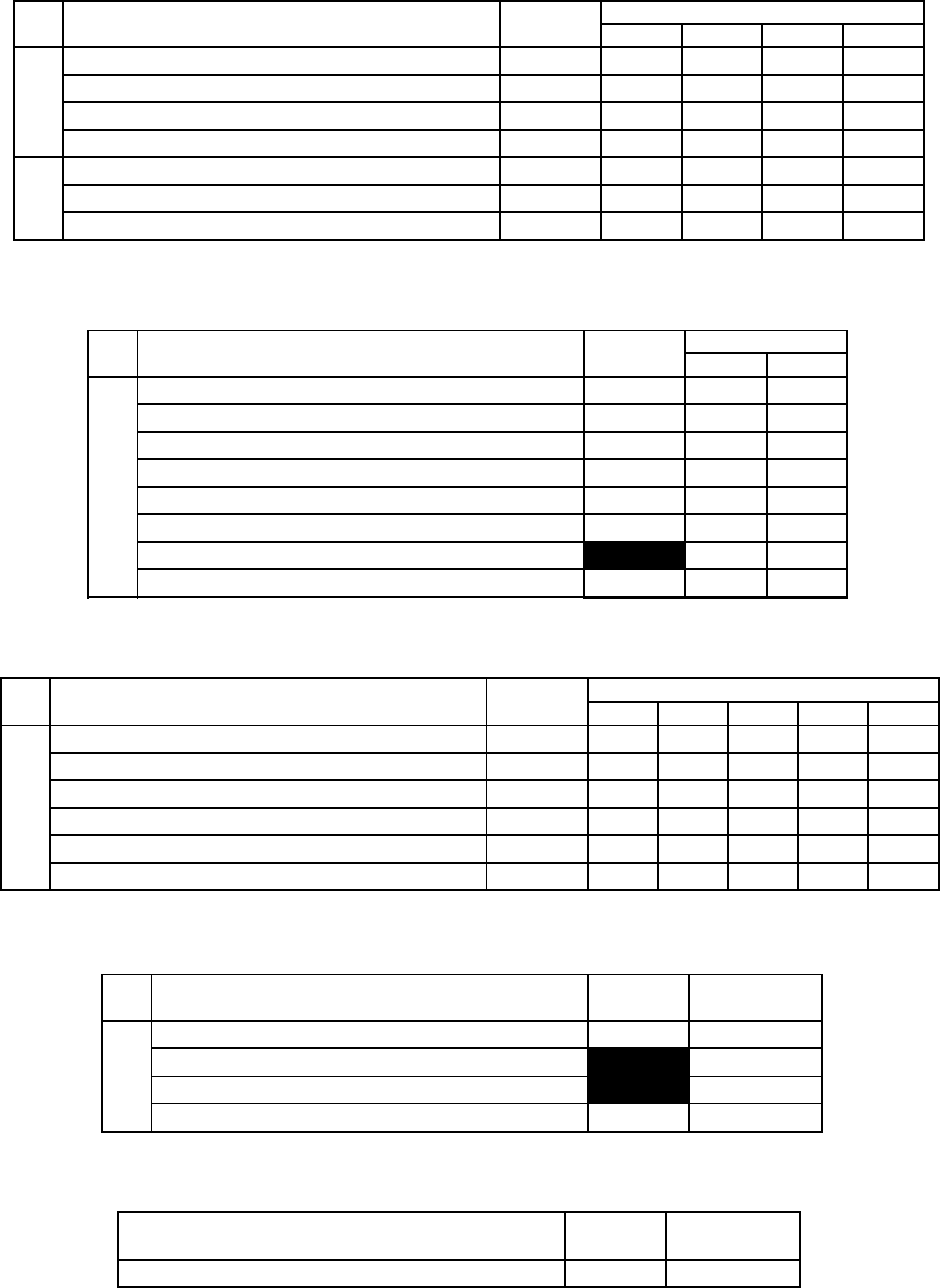
64
REAR FLUE OUTLET CARTON
KEY DESCRIPTION CROWN
PART #
QUANTITY
7 8 10 12
20A
7" REAR OUTLET DAMPER ASSY 333007 1
8" REAR OUTLET DAMPER ASSY 333008 1
10" REAR OUTLET DAMPER ASSY 333010 1
12" REAR OUTLET DAMPER ASSY 333012 1
21B
TOP OUTLET COVER, 7"& 8" OPENING 333017 1 1
TOP OUTLET COVER, 10" OPENING 333020 1
TOP OUTLET COVER, 12" OPENING 333022 1
8" 4"
B.M.P., 4" CARTON COMPLETE* 330404 0 1
B.M.P., 8" CARTON COMPLETE* 330408 1 0
5/16 X 1" CAP SCREW 900410 8 8
5/16" WASHER 900102 8 8
3/8 X 7/8 CAP SCREW 900450 5 5
3/8 FLAT WASHER 90-036 4 4
3/8 LOCK WASHER 9 9
FLEXROPE, 3/16" DENSE 333005 6.5 ft 6.5 ft
SHUTTER DOOR ASSEMBLY INCLUDES:
HANDLE KNOB 1 1
SHUTTER HANDLE 1 1
SHUTTER SPRING 1 1
OBSERVATION PORT SHUTTER 1 1
SPRING PIN 1 1
OBSERVATION PORT ASSEMBLY INCLUDES:
OBSERVATION PORT COVER 1 1
OBSERVATION PORT OUTER GASKET 1 1
OBSERVATION PORT GLASS 1 1
OBSERVATION PORT INNER GASKET 1 1
* INCLUDES B.M.P. AND ALL ITEMS LISTED BELOW INCLUDING THE SHUTTER
DOOR ASSY AND OBSERVATION PORT ASSY.
BURNER MOUNTING PLATE CARTON
KEY
24
25
23
QUANTITYCROWN
PART #
DESCRIPTION
BURNER ADAPTOR PLATE CARTON
KEY DESCRIPTION CROWN
PART #
QUANTITY
920 921 922 923 924
28
BECKETT B.A.P. ASSY, 920 330400 1
BECKETT B.A.P. ASSY, 921 330401 1
BECKETT B.A.P. ASSY, 922 330402 1
BECKETT B.A.P. ASSY, 923 330403 1
BECKETT B.A.P. ASSY, 924 330404 1
BURNER ADAPTOR PLATE GASKET 333405 1 1 1
REAR FLAME OBSERVATION PORT CARTON
KEY DESCRIPTION CROWN
PART # QUANTITY
29
REAR FLAME OBSERVATION PORT ASSY 333000 1
5/16 X 1" CAP SCREW 4
5/16" WASHER 4
FLEXROPE, 3/16" DENSE 333005 2.83 ft
REAR TARGET WALL CARTON
DESCRIPTION CROWN
PART # QUANTITY
TARGET WALL 335025 1

65
STANDARD STEAM TRIM CARTON ASSY.
DESCRIPTION CROWN
PART # QUANTITY
LWCO, #67 400682 1
GLASS SET (11.25" CTR TO CTR) 950082 1
L404F1367 3503800 1
1/2 X 3 BR NIPPLES 95-116 2
1/2" BR. UNION 95-150 2
1/2 X CL BRASS NIPPLE 95-147 2
3/4 BLACK EXTENSION 95-090 1
3/4 X 1/4 BRASS BUSHING 950016 1
90 DEG. BRASS PIGTAIL 95-060B 1
PRESSURE GAUGE 95-070 1
1/2 X 1/4 BRASS BUSHING 95-146 1
3/4" RECESSED HEAD PLUG 950265 3
1" NPT RECESSED HEAD PLUG 950270 4
3" SQ. HD PLUG 950273 2
3 X 1 1/4 BLK BUSHING 950275 1
1-1/2 X 4 BLK NIPPLE 950124 1
1-1/2 BLK TEE 950180 1
1-1/2 BLK SQ. HD PLUG 95-143 1
STANDARD WATER TRIM CARTON ASSY.
DESCRIPTION CROWN
PART # QUANTITY
L4006A2015 35-3510 1
3/4 LONG WELL 35-1020 1
TRIDICATOR GAUGE 95-038 1
1/2 X 1/4 BLK BUSHING 95-053 1
3 X 3/4 BLK BUSHING 950035 1
1/2" NPT RECESSED HEAD PLUG 950260 2
3/4" NPT RECESSED HEAD PLUG 950265 3
1" NPT RECESSED HEAD PLUG 950270 4
3" PLUG 950273 2
4" PLUG 950274 1

66
ACTUATOR (24V, 50 SECOND MOTOR) 332801 1
NIPPLE 3" X 12", (SPECIAL, SCH 40) 332802 1
MOUNTING BRACKET FOR RTC 332803 1
MIX SENSOR, TEKMAR #071, SURFACE MOUNT 332804 1
OUTDOOR AIR SENSOR, TEKMAR #070 332805 1
ACTUATOR (24V, 50 SECOND MOTOR) 332801 1
NIPPLE 3" X 12", (SPECIAL, SCH 40) 332802 1
MOUNTING BRACKET FOR RTC 332803 1
CROWN
PART #
RTC CARTON WITH OUTDOOR RESET
DESCRIPTION QUANTITY
RETURN TEMPERATURE CONTROL (RTC) WITH
BOILER SENSOR & MOUNTING SCREWS 1332800
RTC CARTON WITHOUT OUTDOOR RESET
DESCRIPTION CROWN
PART # QUANTITY
RETURN TEMPERATURE CONTROL (RTC) WITH
BOILER SENSOR & MOUNTING SCREWS 332800 1
CROWN PART # 330800 330810 330850 330851 330852 330853 330854 330855 330856
1" VALVE WITH OUTDOOR RESET 1 1
1" VALVE W/O OUTDOOR RESET 1 1
1 1/4" VALVE WITH OUTDOOR RESET 1 1
1 1/4" VALVE W/O OUTDOOR RESET 1 1
1 1/2" VALVE WITH OUTDOOR RESET 1 1
1 1/2" VALVE W/O OUTDOOR RESET 1 1
2" VALVE WITH OUTDOOR RESET 1 1
2" VALVE W/O OUTDOOR RESET 1 1
2 1/2" VALVE (F165-50) WITH OUTDOOR RESET 1 1
2 1/2" VALVE (F165-50) W/O OUTDOOR RESET 1 1
2 1/2" VALVE (F165) WITH OUTDOOR RESET 1 1
2 1/2" VALVE (F165) W/O OUTDOOR RESET 1 1
3" VALVE WITH OUTDOOR RESET 1 1
3" VALVE W/O OUTDOOR RESET 1 1
1" 3-Way Valve,
MG25-12
1 1/4" 3-Way
Valve, MG32-8
1 1/2" 3-Way
Valve, G138
2" 3-Way Valve,
G151
V
Return Temperature Control (RTC) Packages
(CONSULT APPENDIX B1, B2, B3 & B4 IN THE I/O MANUAL FOR VALVE SELECTION)
2 1/2" 3-Way
Valve, F165
3" 3-Way Valve,
F180
DESCRIPTION
RTC Carton with
Outdoor Reset
RTC Carton
without Outdoor
Reset
2 1/2" 3-Way
Valve, F165-50

67
S24 TANKLESS HEATER CARTON
INCLUDES:
12A S-24 TANKLESS HEATER 1
11 GASKET 330021 1
3/8 X 7/8 "ASME BOLTS" 8
3/8 WASHER 8
HYDROLEVEL 550 LWCO 450560 1
L4006E1109 35-3100 1
3/4 LONG WELL 35-1020 1
#64 LWCO 40-640 1
STEAM FITTING PACKAGE 332001 1
#150S-MD LWCO 40-160 1
STEAM FITTING PACKAGE 332001 1
3/4 BLACK EXTENSION 95-090 1
3/4 X 1/4 BRASS BUSHING 950016 1
90 DEG. BRASS PIGTAIL 95-060B 1
L404C1147 35-3020 1
#11M SWITCH 400100 1
TOP FLUE OUTLET CARTON, 7" 330133 1
TOP FLUE OUTLET CARTON, 8" 330134 1
TOP FLUE OUTLET CARTON, 10" 330135 1
TOP FLUE OUTLET CARTON, 12" 330136 1
BASE RAIL SET, 4-5 SEC. 330604 1
BASE RAIL SET, 6-7 SEC. 330606 1
BASE RAIL SET, 8-9 SEC. 330608 1
BASE RAIL SET, 9-10 SEC. 330610 1
BASE RAIL SET, 11-12 SEC. 330612 1
POLYETHYLENE BLOCK 330010 1
3-WAY VALVE FLANGE KIT: 2-1/2" FLG x 2-1/2" NPT 332950 1
3-WAY VALVE FLANGE KIT: 3" FLANGE x 3" NPT 332953 1
DESCRIPTION
QUANTITY
DESCRIPTION
Miscellaneous Optional Components
D. STEAM FITTING PACKAGE
CROWN
PART # QUANTITY
CROWN
PART # QUANTITY
CROWN
PART # QUANTITY
QUANTITY
Top Flue Outlet
B. STEAM GRAVITY RETURN
CROWN
PART # QUANTITYDESCRIPTION
DESCRIPTION
C. STEAM PUMPED RETURN
DESCRIPTION CROWN
PART #
DESCRIPTION
CSD-1 Packages
DESCRIPTION
1330020
QUANTITY
A. WATER
CROWN
PART #
CROWN
PART #
Tankless Coil Components
KEY

68
STEAM BOILER CARTON ASSY (BECKETT)
DESCRIPTION
RATING PLATE
INSTALLATION MANUAL
WARRANTY
NIPPLE GAUGE
MINIMUM SAFE WATER
LEVEL PLATE
#10 X 1/2" SHEET METAL
SCREWS
HAGO 4.50/45P NOZZLE
HAGO 5.00/45P NOZZLE
HAGO 8.00/45P NOZZLE
NOZZLE INSTRUCTIONS
1 1/4 X 3/4 BUSHING
1 1/4 X 1 BUSHING
4" BLACK PLUG
15 PSI SAFETY VALVE,
CONBRACO 13-211
15 PSI SAFETY VALVE,
CONBRACO 13-202
15 PSI SAFETY VALVE,
CONBRACO 13-213
15 PSI SAFETY VALVE,
CONBRACO 13-214
1-1/2 X 3/4 BLK BUSHING
1-1/2 X 1 BLK BUSHING
1-1/2 X 1-1/4 BLK BUSHING
CROWN PART #
98-111
980417
980418
980920
980150
90-212
130185
13-074
130190
980419
950098
950192
950274
950510
950515
950520
950525
95-096
950185
95-047
24-03SO 1 1 1 1 1 2 1 1 1 1
24-04SO 1 1 1 1 1 2 1 1 1 1
24-05SO 1 1 1 1 1 2 1 1 1 1 1 1
24-06SO 1 1 1 1 1 2 1 1 1 1
24-07SO 1 1 1 1 1 2 1 1 1 1 1
24-08SO 1 1 1 1 1 2 1 1 1
24-09SO 1 1 1 1 1 2 1
24-10SO 1 1 1 1 1 2 1 1 1
24-11SO 1 1 1 1 1 2 1
24-12SO 1 1 1 1 1 2 2 1 1
24-03SG 1 1 1 1 1 2 1 1 1 1
24-04SG 1 1 1 1 1 2 1 1 1 1
24-05SG 1 1 1 1 1 2 1 1 1 1
24-06SG 1 1 1 1 1 2 1 1 1 1
24-07SG 1 1 1 1 1 2 1 1 1
24-08SG 1 1 1 1 1 2 1 1 1
24-09SG 1 1 1 1 1 2 1
24-10SG 1 1 1 1 1 2 1
24-11SG 1 1 1 1 1 2 1
24-12SG 1 1 1 1 1 2 1

69
CROWN PART #
98-111
980417
980418
980600
130185
13-074
130190
980419
950273
95-040
95-081
95-134
950500
95-096
95-027
95-057
95-105
950185
950114
950190
950110
95-047
95-033
95-058
95-031
24-03WO 1 1 1 1 1 1 1 1 1 1
24-04WO 1 1 1 1 1 1 1 1 1 1
24-05WO 1 1 1 1 1 1 1 1 1 1 1 1
24-06WO 1 1 1 1 1 1 1 1 1 1
24-07WO 1 1 1 1 1 1 1 1 1 1 1 1
24-08WO 1 1 1 1 1 1 1 1 1 1
24-09WO 1 1 1 1 1 1 1 1 1 1
24-10WO 1 1 1 1 1 1 1 1 1 1 1 1
24-11WO 1 1 1 1 1 1 1 1 1 1
24-12WO 1 1 1 1 2 1 0 1 1 1 1 1
24-03WG 1 1 1 1 1 1 1 1 1 1
24-04WG 1 1 1 1 1 1 1 1 1 1
24-05WG 1 1 1 1 1 1 1 1 1 1
24-06WG 1 1 1 1 1 1 1 1 1 1
24-07WG 1 1 1 1 1 1 1 1 1 1
24-08WG 1 1 1 1 1 1 1 1 1 1
24-09WG 1 1 1 1 1 1 1 1 1 1
24-10WG 1 1 1 1 1 1 1 1 1 1
24-11WG 1 1 1 1 1 1 1 1 1 1
24-12WG 1 1 1 1 0 1 1 1 1 1
WATER BOILER CARTON ASSY (BECKETT)
1-1/4 X CL BLK NIPPLE
3" BLACK SQ. HD PLUG
1 X CL BLK NIPPLE
1-1/2 X 1-1/4 BLK BUSHING
1-1/4 X 4 BLK NIPPLE
1-1/4 ELBOW
3/4 X CL BLK NIPPLE
1-1/2 X 1 BLK BUSHING
1 X 4 BLK NIPPLE
1 ELBOW
30 PSI RELIEF VALVE,
CONBRACO 10-616-05
1-1/2 X 3/4 BLK BUSHING
3/4 X 3 BLK NIPPLE
3/4 ELBOW
DESCRIPTION
RATING PLATE
INSTALLATION MANUAL
NIPPLE GAUGE
30 PSI RELIEF VALVE,
CONBRACO 10-408-05
30 PSI RELIEF VALVE,
CONBRACO 10-614-05
30 PSI RELIEF VALVE,
CONBRACO 10-615-05
WARRANTY SHEET
HAGO 4.50/45P NOZZLE
HAGO 5.00/45P NOZZLE
HAGO 8.00/45P NOZZLE
NOZZLE INSTRUCTIONS
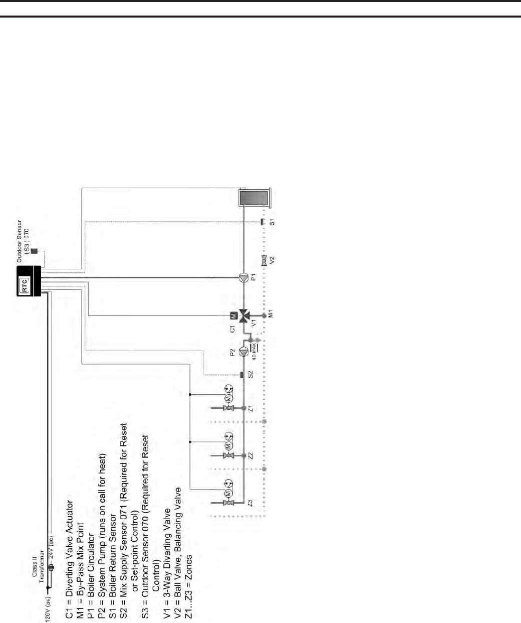
70
A1. 3-way RTC in Primary/Secondary – Heating Only/No DHW; with/without Outdoor Reset (MECHANICAL)
NOTES:
1) Install the boiler as indicated above for systems where return temperatures may be less than 135F and heating application only.
2) The Outdoor Sensor (S3) and the Mix Supply Sensor (S2) are required when the Outdoor Reset feature is selected. The mix sensor must be installed
10 pipe diameters downstream of the system pump, in the primary loop. The mix sensor must be secured to the surface of the pipe using a wire tie or
similar device.
3) The by-pass piping, diverting valve and boiler circulator must be sized using the sizing charts found in Appendix B.
4) Closely spaced tees must connect the branch to the larger header. The Tee centerlines must be no greater than 4 times the larger header pipe diameter.
5) The diverting valve, V1, must be no greater than 11 linear feet of pipe from the Return Sensor, S1.
6) There shall be a MINIMUM of 4 linear feet of pipe between the By-pass Mix Point, M1, and the Return Sensor, S1.
7) The balancing valve in the boiler return line, V2, may be necessary in low head by-pass loop applications.
8) Expansion tanks, air scoops and other components left out for clarity.
9) Observe all applicable plumbing and electrical codes.
This diagram is for reference only. The installer or designer is responsible for the proper selection and design of the sys-
tem.
SECTION VIII - APPENDIX
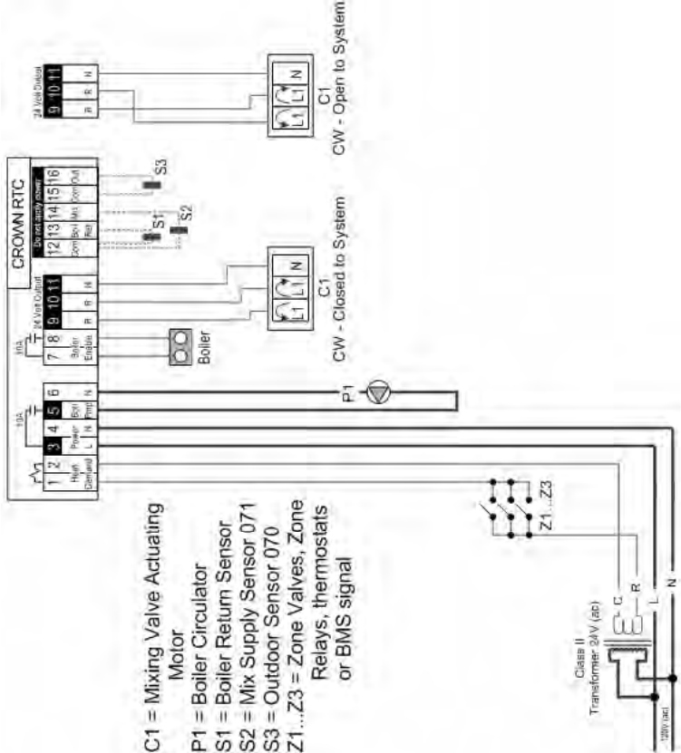
71
A1. 3-way RTC in Primary/Secondary – Heating Only/No DHW; with/without Outdoor Reset (ELECTRICAL)
NOTES:
1) Refer to the I&O to determine correct valve orientation and actuator wiring.
2) 120 VAC supplying the RTC should be separate from the burner/boiler circuit.
3) Heat demand can be any electrical signal consisting of 24 – 240 VAC.
4) Use isolation relays for circulators greater than 1/3 HP. Use motor starters for 3 phase circulators.
5) The Outdoor Sensor (S3) and the Mix Supply Sensor (S2) are required if the Outdoor Reset feature is selected.
6) System Pump (P2) to be operated by zone relay or other installer supplied device.
This diagram is for reference only. The installer or designer is responsible for the proper selection and design of the sys-
tem.
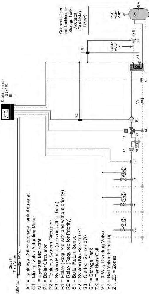
72
A2. 3-way RTC in Primary/Secondary – Heating and DHW using Tankless Coils; with/without Outdoor Reset
(MECHANICAL)
NOTES:
1) Install the boiler as indicated above for systems where return temperatures may be less than 135F and heating/DHW with tankless coils.
2) The Outdoor Sensor (S3) and the Mix Supply Sensor (S2) are required when the Outdoor Reset feature is selected. The mix sensor must be installed 10
pipe diameters downstream of the system pump, in the primary loop. The mix sensor must be secured to the surface of the pipe using a wire tie or similar
device.
3) The by-pass piping, diverting valve and boiler circulator must be sized using the sizing charts found in Appendix B.
4) Closely spaced tees must connect the branch to the larger header. The Tee centerlines must be no greater than 4 times the larger header pipe diameter.
5) The diverting valve, V1, must be no greater than 11 linear feet of pipe from the Return Sensor, S1.
6) There shall be a MINIMUM of 4 linear feet of pipe between the By-pass Mix Point, M1, and the Return Sensor, S1.
7) The balancing valve in the boiler return line, V2, may be necessary in low head by-pass loop applications.
8) Domestic Hot Water must be tempered for safe usage. The tankless aquastat and/or a storage tank aquastat (A1) are normally closed switches. Circuit
breaks on temperature rise.
9) Expansion tanks, air scoops and other components left out for clarity.
10) Observe all applicable plumbing and electrical codes.
This diagram is for reference only. The installer or designer is responsible for the proper selection and design of the
system.

73
NOTES:
1) Refer to the I&O to determine correct valve orientation and actuator wiring.
2) 120 VAC supplying the RTC should be separate from the burner/boiler circuit.
3) Heat demand can be any electrical signal consisting of 24 – 240 VAC.
4) The Outdoor Sensor (S3) and the Mix Supply Sensor (S2) are required if the Outdoor Reset feature is selected.
5) Use isolation relays for circulators greater than 1/3 HP. Use motor starters for 3 phase circulators.
6) Connect the Tankless Aquastat (A1) if you are not using a storage tank. If you are using a storage tank with the tankless heater than using the
storage tank aquastat (A1).
7) System Pump (P3) to be operated by zone relay or other installer supplied device.
This diagram is for reference only. The installer or designer is responsible for the proper selection and design of the
system.
A2. 3-way RTC in Primary/Secondary – Heating and DHW using Tankless Coils; with/without Outdoor Reset (ELECTRICAL)
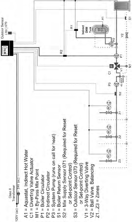
74
A3. 3-way RTC in Primary/Secondary – Heating and DHW using Indirect Water Heater; with/without Outdoor Reset
(MECHANICAL)
NOTES:
1) Install the boiler as indicated above for systems where return temperatures may be less than 135F and heating/DHW with an indirect water heater.
2) The Outdoor Sensor (S3) and the Mix Supply Sensor (S2) are required when the Outdoor Reset feature is selected. The mix sensor must be installed 10
pipe diameters downstream of the system pump, in the primary loop. The mix sensor must be secured to the surface of the pipe using a wire tie or similar
device.
3) The by-pass piping, diverting valve and boiler circulator must be sized using the sizing charts found in Appendix B.
4) Closely spaced tees must connect the branch to the larger header. The Tee centerlines must be no greater than 4 times the larger header pipe diameter.
5) The diverting valve, V1, must be no greater than 11 linear feet of pipe from the Return Sensor, S1.
6) There shall be a MINIMUM of 4 linear feet of pipe between the By-pass Mix Point, M1, and the Return Sensor, S1.
7) The balancing valve in the boiler return line, V2, may be necessary in low head by-pass loop applications.
8) The indirect heater aquastat (A1) is a normally closed switch. Circuit breaks on temperature rise.
9) Expansion tanks, air scoops and other components left out for clarity.
10) Observe all applicable plumbing and electrical codes.
This diagram is for reference only. The installer or designer is responsible for the proper selection and design of the
system.
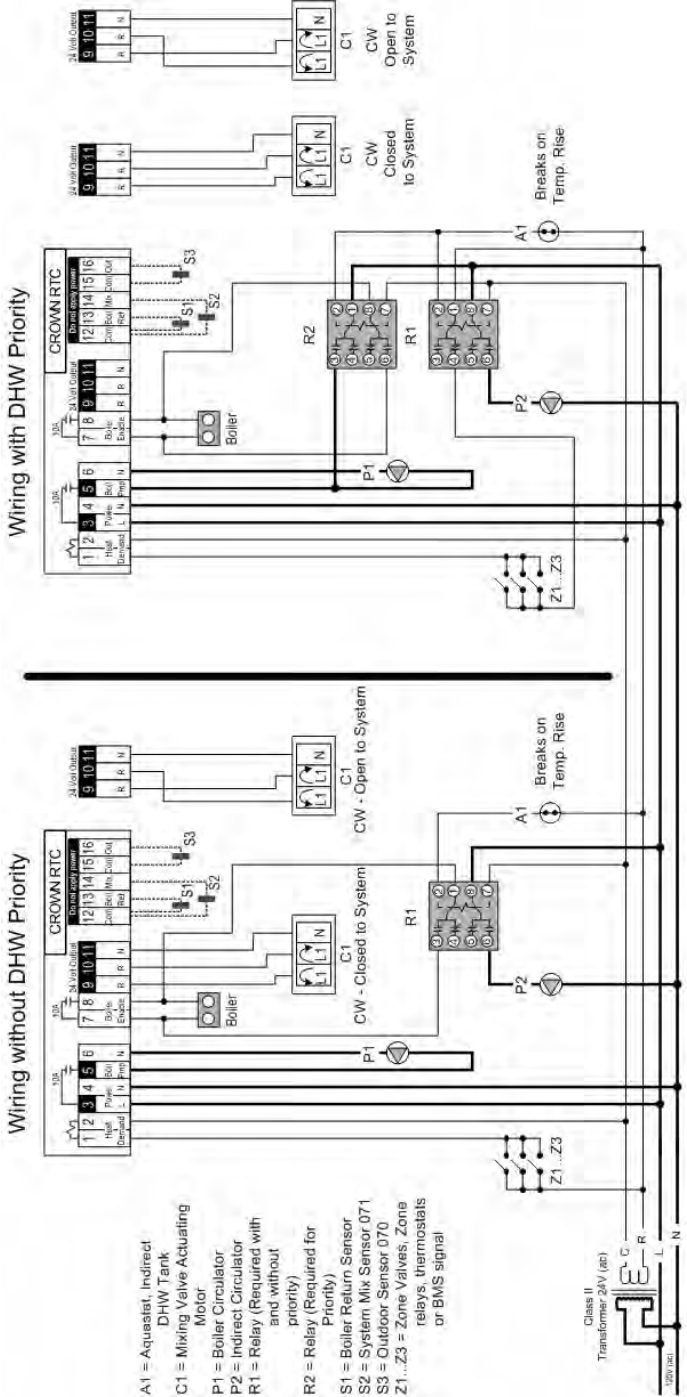
75
A3. 3-way RTC in Primary/Secondary – Heating and DHW using Indirect Water Heater; with/without Outdoor Reset
(ELECTRICAL)
NOTES:
1) Refer to the I&O to determine correct valve orientation and actuator wiring.
2) 120 VAC supplying the RTC should be separate from the burner/boiler circuit.
3) Heat demand can be any electrical signal consisting of 24 – 240 VAC.
4) The Outdoor Sensor (S3) and the Mix Supply Sensor (S2) are required if the Outdoor Reset feature is selected.
5) Use isolation relays for circulators greater than 1/3 HP. Use motor starters for 3 phase circulators.
6) System Pump (P3) to be operated by zone relay or other installer supplied device.
This diagram is for reference only. The installer or designer is responsible for the proper selection and design of the
system.
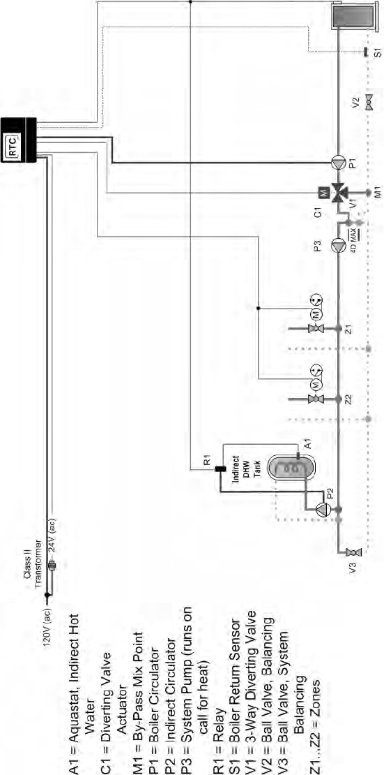
76
A4. 3-way RTC in Primary/Secondary – Heating and DHW using Indirect Water Heater on Primary Loop; without Outdoor
Reset (MECHANICAL)
NOTES:
1) Install the boiler as indicated above for systems where return temperatures may be less than 135F and heating/DHW with an indirect water heater.
2) This arrangement is NOT recommended for outdoor reset applications. The reset temperature will constantly change DHW water performance.
3) The by-pass piping, diverting valve and boiler circulator must be sized using the sizing charts found in Appendix B.
4) A domestic hot water priority could be used provided the diversion from the heating system loop does not impact the system heater’s performance.
5) Closely spaced tees must connect the branch to the larger header. The Tee centerlines must be no greater than 4 times the larger header pipe diameter.
6) The diverting valve, V1, must be no greater than 11 linear feet of pipe from the Return Sensor, S1.
7) There shall be a MINIMUM of 4 linear feet of pipe between the By-pass Mix Point, M1, and the Return Sensor, S1.
8) The balancing valve in the boiler return line, V2, may be necessary in low head by-pass loop applications.
9) The indirect heater aquastat (A1) is a normally closed switch. Circuit breaks on temperature rise.
10) Expansion tanks, air scoops and other components left out for clarity.
11) Observe all applicable plumbing and electrical codes.
This diagram is for reference only. The installer or designer is responsible for the proper selection and design of the
system.
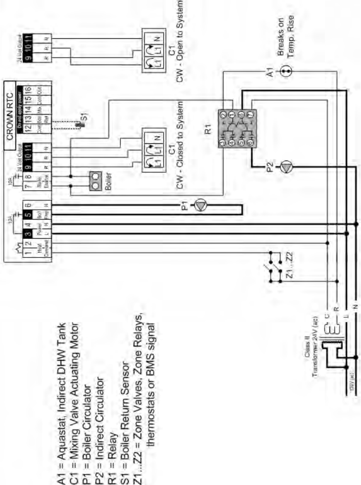
77
A4. 3-way RTC in Primary/Secondary – Heating and DHW using Indirect Water Heater on Primary Loop; without Outdoor
Reset (ELECTRICAL)
NOTES:
1) Refer to the I&O to determine correct valve orientation and actuator wiring.
2) 120 VAC supplying the RTC should be separate from the burner/boiler circuit.
3) Heat demand can be any electrical signal consisting of 24 – 240 VAC.
4) Use isolation relays for circulators greater than 1/3 HP. Use motor starters for 3 phase circulators.
5) System Pump (P3) to be operated by zone relay or other installer supplied device.
This diagram is for reference only. The installer or designer is responsible for the proper selection and design of the
system.
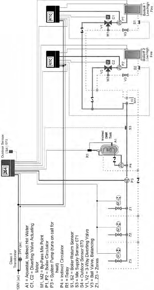
78
A5. 3-way Multiple Boiler RTC in Primary/Secondary – Heating and DHW using Indirect Water Heater on Primary Loop;
Using Sequencer with & without Outdoor Reset (MECHANICAL)
NOTES:
1) Install the boiler as indicated above for systems where return temperatures may be less than 135F and heating/DHW with an indirect water heater.
2) The Outdoor Sensor (S4) and the Mix Supply Sensor (S3) are required when the Outdoor Reset feature is selected. An appropriate sequencer must also
be selected. The mix sensor must be installed 10 pipe diameters downstream of the system pump, in the primary loop. The mix sensor must be secured
to the surface of the pipe using a wire tie or similar device.
3) The by-pass piping, diverting valve and boiler circulator must be sized using the sizing charts found in Appendix B.
4) A domestic hot water priority could be used provided the diversion from the heating system loop does not impact the system heater’s performance.
5) Closely spaced tees must connect the branch to the larger header. The Tee centerlines must be no greater than 4 times the larger header pipe diameter.
6) The diverting valves, V1 & V2, must be no greater than 11 linear feet of pipe from the Return Sensors, S1 & S2.
7) There shall be a MINIMUM of 4 linear feet of pipe between the By-pass Mix Points, M1 & M2, and the Return Sensors, S1 & S2.
8) The balancing valves in the boiler return lines, V3, may be necessary in low head by-pass loop applications.
9) The indirect heater aquastat (A1) is a normally closed switch. Circuit breaks on temperature rise.
10) Expansion tanks, air scoops and other components left out for clarity.
11) Observe all applicable plumbing and electrical codes.
This diagram is for reference only. The installer or designer is responsible for the proper selection and design of the
system.
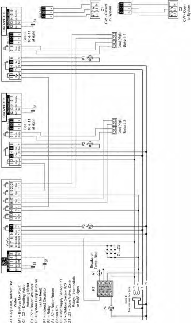
79
A5. 3-way Multiple Boiler RTC in Primary/Secondary – Heating and DHW using Indirect Water Heater on Primary Loop;
Using Sequencer with & without Outdoor Reset (ELECTRICAL)
NOTES:
1) Refer to the I&O to determine correct valve orientation and actuator wiring.
2) 120 VAC supplying the RTC should be separate from the burner/boiler circuit.
3) Heat demand can be any electrical signal consisting of 24 – 240 VAC.
4) Use isolation relays for circulators greater than 1/3 HP. Use motor starters for 3 phase circulators.
5) System Pump (P3) to be operated by zone relay or other installer supplied device.
This diagram is for reference only. The installer or designer is responsible for the proper selection and design of the
system.
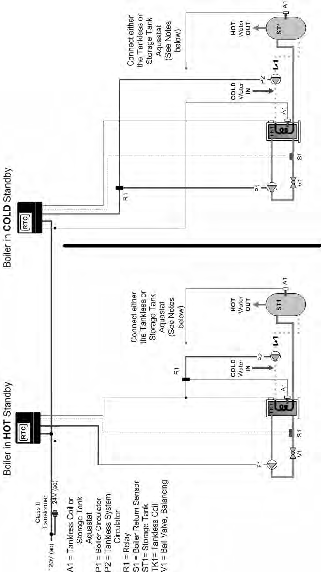
80
A6. Tankless Application Only with RTC – NO Building Heat; with and without storage tank (MECHANICAL)
NOTES:
1) Install the boiler as indicated above for systems where the boiler return temperatures may be less than 135F and heating DHW with a tankless coil.
2) The boiler circulator must be sized using the sizing charts found in Appendix B.
3) The return sensor, S1, shall be installed at the return of the boiler. The boiler circulator may be located anywhere within the recirculation loop.
4) The balancing valve in the boiler return line, V1, may be necessary in low head by-pass loop applications.
5) Domestic Hot Water must be tempered for safe usage. The tankless aquastat and/or a storage tank aquastat (A1) are normally closed switches. Circuit
breaks on temperature rise.
6) Expansion tanks, air scoops and other components left out for clarity.
7) Observe all applicable plumbing and electrical codes.
This diagram is for reference only. The installer or designer is responsible for the proper selection and design of the
system.
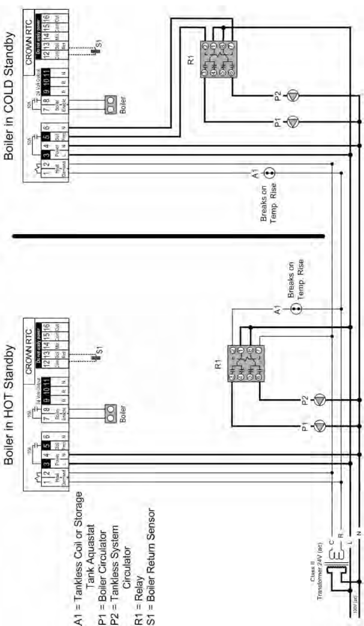
81
A6. Tankless Application Only with RTC – NO Building Heat; with and without storage tank (ELECTRICAL)
NOTES:
1) Refer to the I&O to determine correct valve orientation and actuator wiring.
2) 120 VAC supplying the RTC may or may not be separate from the burner/boiler circuit.
3) Heat demand can be any electrical signal consisting of 24 – 240 VAC.
4) Use isolation relays for circulators greater than 1/3 HP. Use motor starters for 3 phase circulators.
5) In COLD STANDBY applications, set the “OPEN DELAY” variable to 30 seconds.
This diagram is for reference only. The installer or designer is responsible for the proper selection and design of the
system.
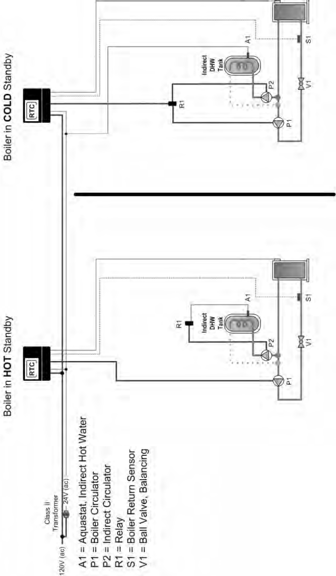
82
A7. Indirect Application Only with RTC – NO Building Heat (MECHANICAL)
NOTES:
1) Install the boiler as indicated above for systems where the boiler return temperatures may be less than 135F and heating DHW with an indirect water
heater or heat exchanger.
2) The boiler circulator must be sized using the sizing charts found in Appendix B.
3) The return sensor, S1, shall be installed at the return of the boiler. The boiler circulator may be located anywhere within the recirculation loop.
4) The balancing valve in the boiler return line, V1, may be necessary in low head by-pass loop applications.
5) The indirect heater aquastat (A1) is a normally closed switch. Circuit breaks on temperature rise.
6) Expansion tanks, air scoops and other components left out for clarity.
7) Observe all applicable plumbing and electrical codes.
This diagram is for reference only. The installer or designer is responsible for the proper selection and design of the
system.
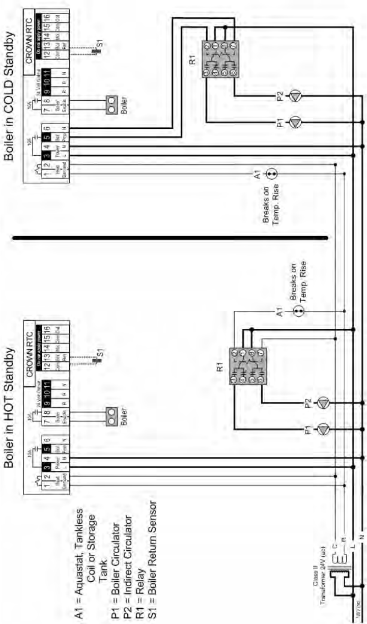
83
A7. Indirect Application Only with RTC – NO Building Heat (ELECTRICAL)
NOTES:
1) Refer to the I&O to determine correct valve orientation and actuator wiring.
2) 120 VAC supplying the RTC may or may not be separate from the burner/boiler circuit.
3) Heat demand can be any electrical signal consisting of 24 – 240 VAC.
4) Use isolation relays for circulators greater than 1/3 HP. Use motor starters for 3 phase circulators.
5) In COLD STANDBY applications, set the “OPEN DELAY” variable to 30 seconds.
This diagram is for reference only. The installer or designer is responsible for the proper selection and design of the
system.
84
APPENDIX B1 - Series 24 Boiler Circulator and Diverting Valve Selection Chart, 20°F & 40°F DT, TACO
)laitnereffiDF°02(OCAT-noitceleSrotalucriCrelioB42seireS
EZIS
RBI
SSORG
TUPTUO
)HBM(
LATOT
MPG
epiP
eziS
noitalucriceRrelioB
yaW-3 pmuPgnitalucriCOCAT
evlaV
eziS
evlaV
traP
rebmuN
.oNledoM "pmI PH MPR
30-42 243 53 "0.2 TPN"5.1 258033 111LI A/N 8/1 5271
40-42 174 84 "0.2 TPN"5.1 258033 5161 "7.4 3/1 0571
5
0-42 436 56 "0.2 TPN"2 358033 1161 "5.4 3/1 0571
6
0-42 797 18 "
5.2 egnalF"5.2* 458033 6002VK "3.4 1** 0571
70-42 739 69 "5.2 egnalF"5.2* 458033 5361 "5.4 2/1** 0
571
80-42 7801 111 "5.2 egnalF"5.2* 458033 5361 "9.4 4/3** 0
571
90-42 6131 431 "0.3 egnalF"5.2 558033 6003VK "7.4 1** 0571
0
1-42 5051 351 "0.3 egnalF"5.2 558033 6003VK "0.5 1** 0571
1
1-42 0961 171 "0.3 egnalF"5.2 558033 6003VK "3.5 1** 0571
2
1-42 2581 091 "0.4 egnalF"0.3 658033 7003VK "6.5 1** 0571
.
evlavyaw-3"½205-561FledoM*
.rewoPesahP3rofretratSrotoMesU.rewoPesahPelgniSrofyaleRlanoitiddAesU**
)laitnereffiDF°04(OCAT-noitceleSrotalucriCrelioB42seireS
EZIS
RBI
SSORG
TUPTUO
)HBM(
LATOT
MPG
epiP
eziS
noitalucriceRrelioB
yaW-3 pmuPgnitalucriCOCAT
evlaV
eziS
evlaV
traP
rebmuN
ledoM
.oN "pmI PH MPR
30-42 243 71 "5.1 TPN"0.1 058033 700 A/N 52/1 0523
40-42 174 42 "5.1 TPN"52.1 158033 0100 A/N 8/1 0523
5
0-42 436 23 "5.1 TPN"5.1 258033 C111 A/N 8/1 5271
6
0-42 797 04 "5.1 TPN"5.1 258033 C121 A/N 4/1 5271
7
0-42 739 84 "0.2 TPN"0.2 358033 C021 A/N 6/1 5271
8
0-42 7801 65 "0.2 TPN"0.2 358033 1161 "1.4 4/1 0571
9
0-42 6131 76 "0.2 TPN"0.2 358033 C221 A/N 4/1 5271
0
1-42 5051 67 "5.2 egnalF"5.2* 458033 C121 A/N 4/1 5271
1
1-42 0961 68 "5.2 egnalF"5.2* 458033 131 A/N 3/1 5271
2
1-42 2581 59 "5.2 egnalF"5.2* 458033 5361 "5.4 2/1** 0
571
.evlavyaw-3"½205-561FledoM*
.rewoPesahP3rofretratSrotoMesU.rewoPesahPelgniSrofyaleRlanoitiddAesU**
85
APPENDIX B2 - Series 24 Boiler Circulator and Diverting Valve Selection Chart, 20°F & 40°F ∆T, Grundfos
)laitnereffiDF°02(sofdnurG-noitceleSrotalucriCrelioB42seireS
EZIS
RBI
SSORG
TUPTUO
)HBM(
LATOT
MPG
epiP
eziS
noitalucriceRrelioB
yaW-3 pmuPgnitalucriCsofdnurG
evlaV
eziS
evlaV
traP
rebmuN
.oNledoM "pmI PH MPR
30-42 243 53 "0.2 TPN"5.1 258033 4/04-23SPU 93.3 3/1 7661
40-42 174 84 "0.2 TPN"5.1 258033 2/08-23SPU 25.2 2/1** 0
043
50-42 436 56 "0.2 TPN"2 358033 4/08-04SPU 68.4 2/1** 7
851
60-42 797 18 "5.2 egnalF"5.2* 458033 4/08-04SPU 68.4 2/1** 7
851
70-42 739 69 "5.2 egnalF"5.2* 458033 4/08-05SPU 79.4 4/
3** 7061
80-42 7801 111 "5.2 egnalF"5.2* 458033 2/08-05SPU 19.2 4/3** 6
243
90-42 6131 431 "0.3 egnalF"5.2 558033 4/04-08PT 37.3 2/1** 0
571
01-42 5051 351 "0.3 egnalF"5.2 558033 4/04-001PT 01.4 1** 0571
1
1-42 0961 171 "0.3 egnalF"5.2 558033 4/04-001PT 01.4 1** 0571
2
1-42 2581 091 "0.4 egnalF"0.3 658033 4/08-001PT 42.5 2** 0571
.
evlavyaw-3"½205-561FledoM*
.rewoPesahP3rofretratSrotoMesU.rewoPesahPelgniSrofyaleRlanoitiddAesU**
)laitnereffiDF°04(sofdnurG-noitceleSrotalucriCrelioB42seireS
EZIS
RBI
SSORG
TUPTUO
)HBM(
LATOT
MPG
epiP
eziS
noitalucriceRrelioB
yaW-3 pmuPgnitalucriCsofdnurG
evlaV
eziS
evlaV
traP
rebmuN
.oNledoM "pmI PH MPR
30-42 243 71 "5.1 TPN"0.1 058033 4/04-23SPU 93.3 3/1 4951
40-42 174 42 "5.1 TPN"52.1 158033 4/04-23SPU 93.3 3/1 7661
5
0-42 436 23 "5.1 TPN"5.1 258033 4/04-23SPU 93.3 3/1 2171
6
0-42 797 04 "5.1 TPN"5.1 258033 2/08-23SPU 25.2 2/1** 0
043
70-42 739 84 "0.2 TPN"0.2 358033 2/08-23SPU 25.2 2/1** 0
043
80-42 7801 65 "
0.2 TPN"0.2 358033 4/08-04SPU 68.4 2/1** 0541
90-42 6131 76 "
0.2 TPN"0.2 358033 4/08-04SPU 68.4 2/1** 7851
01-42 5051 67 "
5.2 egnalF"5.2* 458033 4/08-04SPU 68.4 2/1** 7851
11-42 0961 68 "
5.2 egnalF"5.2* 458033 4/08-04SPU 68.4 2/1** 8861
21-42 2581 59 "
5.2 egnalF"5.2* 458033 4/08-05SPU 79.4 4/3** 7061
.evlavyaw-3"½205-561FledoM*
.rewoPesahP3rofretratSrotoMesU.rewoPesahPelgniSrofyaleRlanoitiddAesU**
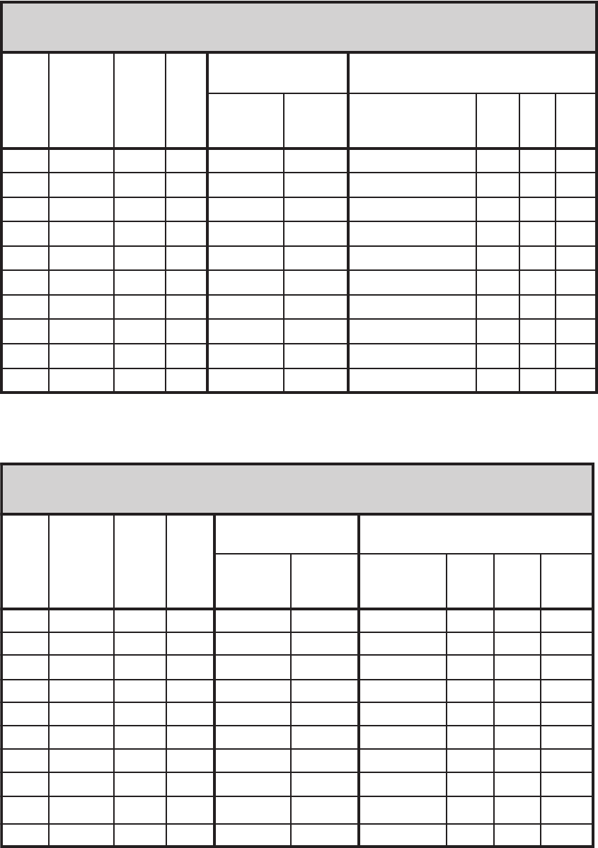
86
APPENDIX B3 - Series 24 Boiler Circulator and Diverting Valve Selection Chart, 20°F & 40°F ∆T,
Bell and Gossett
F°02(ttessoGdnalleB-noitceleSrotalucriCrelioB42seireS
)laitnereffiD
EZIS
RBI
SSORG
TUPTUO
)HBM(
LATOT
MPG
epiP
eziS
noitalucriceRrelioB
yaW-3 pmuPgnitalucriCttessoGdnalleB
evlaV
eziS
evlaV
traP
rebmuN
.oNledoM "pmI PH MPR
30-42 243 53 "0.2 TPN"5.1 258033 "5.1-63-LP .dtS 6/1 0033
40-42 174 84 "
0.2 TPN"5.1 258033 "2-57-LP .dtS 6/1 0043
50-42 436 56 "
0.2 TPN"2 358033 "2-031-LP .dtS 5/2** 0023
6
0-42 797 18 "
5.2 egnalF"5.2* 458033 "2-031-LP .dtS 5/2** 0023
70-42 739 69 "
5.2 egnalF"5.2* 458033 "2-031-LP .dtS 5/2** 0023
80-42 7801 111 "5.2 e
gnalF"5.2* 458033 "2-016.doM,06.reS "4 2/1** 0571
90-42 6131 431 "0.3 e
gnalF"5.2 558033 "2-016.doM,06.reS "4 2/1** 0571
01-42 5051 351 "0.3 e
gnalF"5.2 558033 B7x3x3.doM,08.reS "5 1** 0571
11-42 0961 171 "0.3 e
gnalF"5.2 558033 B7x3x3.doM,08.reS "5 1** 0571
21-42 2581 091 "0.4 e
gnalF"0.3 658033 B7x3x3.doM,08.reS "5 1** 0571
* .evlavyaw-3"½205-561FledoM
.rewoPesahP3rofretratSrotoMesU.rewoPesahPelgniSrofyaleRlanoitiddAesU**
F°04(ttessoGdnalleB-noitceleSrotalucriCrelioB42seireS
)laitnereffiD
EZIS
RBI
SSORG
TUPTUO
)HBM(
LATOT
MPG
epiP
eziS
noitalucriceRrelioB
yaW-3 pmuPgnitalucriCttessoGdnalleB
evlaV
eziS
evlaV
traP
rebmuN
.oNledoM "pmI PH MPR
30-42 243 71 "5.1 TPN"0.1 058033 33-FRN .dtS 51/1 0592
40-42 174 42 "5.1 TPN"52.1 158033 63-LP .dtS 6/1 0
033
50-42 436 23 "5.1 TPN"5.1 258033 63-LP .dtS 6/1 0
033
60-42 797 04 "5.1 TPN"5.1 258033 54-LP .dtS 6/1 0
033
70-42 739 84 "0.2 TPN"0.2 358033 57-LP .dtS 6/1 0
043
80-42 7801 65 "
0.2 TPN"0.2 358033 57-LP .dtS 6/1 0043
90-42 6131 76 "
0.2 TPN"0.2 358033 "2-031-LP .dtS 5/2** 0023
01-42 5051 67 "
5.2 egnalF"5.2* 458033 "2-031-LP .dtS 5/2** 0023
11-42 0961 68 "
5.2 egnalF"5.2* 458033 "2-031-LP .dtS 5/2** 0
023
21-42 2581 59 "5.2 egnalF"5.2* 458033 "2-031-LP .dtS 5/2** 0023
.evlavyaw-3"½205-561FledoM*
.rewoPesahP3rofretratSrotoMesU.rewoPesahPelgniSrofyaleRlanoitiddAesU**
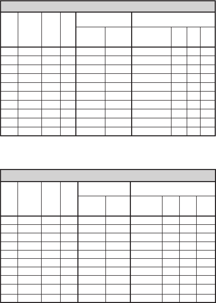
87
APPENDIX B4 - Series 24 Boiler Circulator and Diverting Valve Selection Chart, 20°F & 40°F ∆T,
Armstrong
)laitnereffiDF°02(gnortsmrA-noitceleSrotalucriCrelioB42seireS
EZIS
RBI
SSORG
TUPTUO
)HBM(
LATOT
MPG
epiP
eziS
noitalucriceRrelioB
yaW-3 pmuPgnitalucriCgnortsmrA
evlaV
eziS
evlaV
traP
rebmuN
.oNledoM "pmI PH MPR
30-42 243 53 "0.2 TPN"5.1 258033 01-E lluF 6/1 ---
40-42 174 84 "
0.2 TPN"5.1 258033 54-S 578.3 4/1 0081
50-42 436 56 "
0.2 TPN"2 358033 64-S 52.4 3/1 0021
60-42 797 18 "
5.2 egnalF"5.2* 458033 64-S 52.4 3/1 0021
70-42 739 69 "
5.2 egnalF"5.2* 458033 6x3x30834 40.5 3/1 0021
80-42 7801 111 "5.2 e
gnalF"5.2* 458033 6x3x30834 765.5 2/1** 0021
9
0-42 6131 431 "0.3 e
gnalF"5.2 558033 6x3x30834 32.5 3/1 0021
01-42 5051 351 "0.3 e
gnalF"5.2 558033 6x4x40834 179.4 2/1** 0021
1
1-42 0961 171 "0.3 e
gnalF"5.2 558033 6x4x40834 173.5 2/1** 0021
21-42 2581 091 "0.4 e
gnalF"0.3 658033 6x4x40834 198.4 2/1** 0021
* .evlavyaw-3"½205-561FledoM
.rewoPesahP3rofretratSrotoMesU.rewoPesahPelgniSrofyaleRlanoitiddAesU**
)laitnereffiDF°04(gnortsmrA-noitceleSrotalucriCrelioB42seireS
EZIS
RBI
SSORG
TUPTUO
)HBM(
LATOT
MPG
epiP
eziS
noitalucriceRrelioB
yaW-3 pmuPgnitalucriCgnortsmrA
evlaV
eziS
evlaV
traP
rebmuN
.oNledoM "pmI PH MPR
30-42 243 71 "5.1 TPN"0.1 058033 52-S 57.2 6/1 0081
40-42 174 42 "5.1 TPN"52.1 158033 52-S 57.2 21/1 0081
50-42 436 23 "5.1 TPN"5.1 258033 8-E lluF 6/1 0
063
60-42 797 04 "5.1 TPN"5.1 258033 53-S 573.3 6/1 0081
70-42 739 84 "0.2 TPN"0.2 358033 64-S 573.3 4/1 0081
80-42 7801 65 "
0.2 TPN"0.2 358033 54-S 578.3 4/1 0081
90-42 6131 76 "
0.2 TPN"0.2 358033 64-S 578.3 3/1 0081
01-42 5051 67 "
5.2 egnalF"5.2* 458033 6x3x30834 899.4 3/1 0021
11-42 0961 68 "
5.2 egnalF"5.2* 558033 6x3x30834 776.4 3/1 0021
21-42 2581 59 "5.2 egnalF"5.2* 658033 6x3x30834 910.5 3/1 0021
.evlavyaw-3"½205-561FledoM*
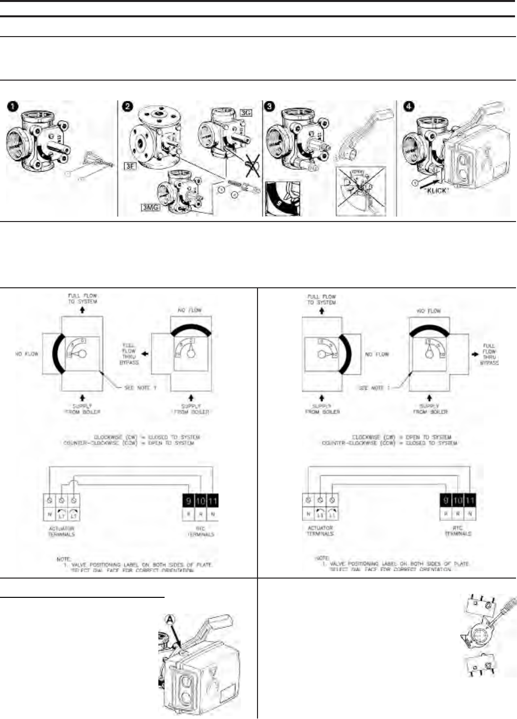
88
APPENDIX C – VALVE AND ACTUATOR MOUNTING INSTRUCTIONS
Application
For use with ESBE ½” to 6” 3-Way and 4-Way rotary valves for mixing and diverting applications. Use with 24Vac 3-point “floating” signal controller.
Mounting the Motor
1. Place drive sleeve onto shaft and secure with bolt . Check that the valve is in mid-position (sleeve pointer set to position 5 on scale plate).
2. Mount threaded stud - in one of the threaded holes. For 1½” and 2" valves replace one of the cover bolts with the threaded rod. Tighten
mounting piece onto threaded rod.
3. Mount handle over drive sleeve set pointer to 5 on the scale plate. Handle must be mounted opposite to the pointer of the drive sleeve.
4. Mount motor onto sleeve so that the mounting piece m fits into the locking piece o. Push locking piece to lock in place. Labels are supplied
to indicate the direction of rotation. Determine the direction of rotation and mount the correct label under the plastic front cover of motor.
Manual Operation
Always disconnect power before operating by hand. Note
position of drive sleeve pointer to be returned to. Depress
the gray button, “A”, on the side to release
the handle. The valve can now be operated
manually. Never manually operate when
gears are engaged.
Adjusting Cams
The position of the cams is changed by fitting a screw-
driver in the slot and moving the cam to the desired
position.The topmost cam operates the auxiliary
switch (upper switch – NOT USED). The middle and
lower cams determine the degree of rotation (30° to
180°). To access, remove the actuator cover to gain
access to the middle and lower cams.The valve rota-
tion must be set before operation can begin. Adjust
the cam so that each end switch is made when the
valve is fully open (pointer towards “0”) and when the
valve is fully closed (pointer towards “10”). Depress
the “Test” switch on the RTC control to test for proper valve operation.

89
SERVICE RECORD
DATE SERVICE PERFORMED

90
Manufacturer of Hydronic Heating Products
P.O. Box 14818 3633 I. Street
Philadelphia, PA 19134
Tel: (215) 535-8900 • Fax: (215) 535-9736 • www.crownboiler.com
D E S I G N E D T O LE A D
PN: 980417
S24 - 12/05
