Crown Boiler Chb68 112L Users Manual
CHC68-96L to the manual 66f6cc67-0283-4f88-9260-46e93d100632
2015-02-05
: Crown-Boiler Crown-Boiler-Chb68-112L-Users-Manual-531459 crown-boiler-chb68-112l-users-manual-531459 crown-boiler pdf
Open the PDF directly: View PDF ![]() .
.
Page Count: 6
- CHB68-112L CHC68-96L CLBF68-112L
- CLBR68-112L
- ? CAUTION:
- ONLY a qualified oil-heating contractor shall install and adjust this oil burner, using calibrated combustion test instruments, to ensure safe and reliable operation of the furnace.
- ONLY two (2) oil burner models shall be used with the Crown furnaces,
- R.W. Beckett model AF specification number EFL-102, or
- Carlin Combustion model EZ1-HP specification number 10250.
- This furnace has been tested and approved for use when burning No. 2 distillate fuel (home heating) oil ONLY.
- Introduction:
- These instructions list the steps required to field install a R.W. Beckett or a Carlin Combustion oil burner assembly in any of the Crown oil-fired furnace models previously noted. The factory ships all Crown furnace models without the oil burner install

Instructions for Installation and
Connection of Oil Burner to Furnace
For Furnace Models:
CHB68-112L CHC68-96L CLBF68-112L
CLBR68-112L
: Failure to follow these instructions exactly may result in a fire or
explosion causing property damage, personal injury or loss of life.
DO NOT store or use gasoline or other flammable vapors and liquids in the vicinity of
this or any other appliance.
What to do if you find an oil leak:
• DO NOT try to operate this appliance.
• If possible, close the manual fuel shutoff valve on the oil supply tank.
• Immediately call your oil supplier. Follow the oil supplier’s instructions.
• If you cannot reach your oil supplier, call the fire department.
A qualified installer, service agency, or the oil supplier must perform installation and
service.
These instructions should be:
• read prior to installation.
• retained for qualified service personnel
• reviewed before performing any service or maintenance.
Crown Boiler Company
3633 “I” Street
Philadelphia, Pennsylvania 19134
MO-432
ECN4514-MA

Only qualified service personnel shall perform installation and service.
2
c
cc
c CAUTION:
• ONLY a qualified oil-heating contractor shall install and adjust this oil
burner, using calibrated combustion test instruments, to ensure safe and
reliable operation of the furnace.
• ONLY two (2) oil burner models shall be used with the Crown furnaces,
o R.W. Beckett model AF specification number EFL-102, or
o Carlin Combustion model EZ1-HP specification number 10250.
• This furnace has been tested and approved for use when burning No. 2
distillate fuel (home heating) oil ONLY.
Introduction:
These instructions list the steps required to field install a R.W. Beckett or a Carlin
Combustion oil burner assembly in any of the Crown oil-fired furnace models
previously noted. The factory ships all Crown furnace models without the oil burner
installed. The burner package is separate from the furnace. As one of several tasks
necessary to complete installation of the furnace, the burner must be removed from
the shipping carton, mounted in the furnace, and connected to the furnace wiring
harness. Consult the furnace instruction manual, Crown Oil-Fired Central Furnace
Installation, Operation, and Service Manual with User’s Information Section, for
further assembly and adjustment requirements.
The size of nozzle installed in the oil burner determines the rate of heat output from
(heating capacity of) the furnace. Four (4) heat input rates are permissible:
85,000; 105,000; 120,000; and 140, 000 BTUH.
Base oil nozzle selection (i.e. heating capacity of the furnace) on a rate of heat loss
(heating load) calculation performed for the building. Use the procedures developed
in manuals provided by the Air Conditioning Contractors of America (ACCA) or the
American Society of Heating, Refrigeration and Air Conditioning Engineers, Inc.
(ASHRAE) to make these calculations.
Refer to the Residential Load Calculation, Manual J, from the ACCA, and the
ASHRAE Handbook Fundamentals volume, from ASHRAE, for recommended
practices in heating load calculation for a residence. To obtain copies of these
publications for a fee, contact the ACCA and the ASHRAE at the addresses given in
Appendix A of the furnace instruction manual.
Installation:
The oil burner ships in a carton separate from the furnace. In the field, it is
necessary to mount the oil burner, secure it to the furnace, and connect the wiring
harness to complete the burner installation. Refer to the following steps.
Only qualified service personnel shall perform installation and service.
3
1) Remove the oil burner from the shipping carton and remove any shipping
materials adhering to the burner. Collect and save the burner mounting gasket
and any instructions furnished with the burner.
2) If it is necessary to adjust the heating capacity of the furnace, by changing the oil
burner nozzle, refer to the following directions.
a) The oil nozzle is factory installed in the oil burner. To change the oil nozzle,
remove the nozzle through the front end of the burner air tube. Consult the oil
burner manufacturer’s operating instructions (included with the burner) for
detailed instructions on this procedure.
b) Install an appropriate replacement nozzle of the correct size, spray angle,
and spray type. Refer to the Specification Sheets, in Appendix C of the
furnace instruction manual, for nozzle recommendations.
3) On highboy furnace models, remove the burner access panel. This panel will be
the upper access panel on the front of the furnace. On lowboy models, remove
the front access panel. On horizontal / counterflow models, the burner is
mounted on the front surface of the furnace.
4) Remove the three (3), 5/16 in. brass hex machine screw nuts and the three (3)
steel flat washers from the threaded studs protruding through the burner
mounting plate on the furnace. Retain this hardware for later reuse.
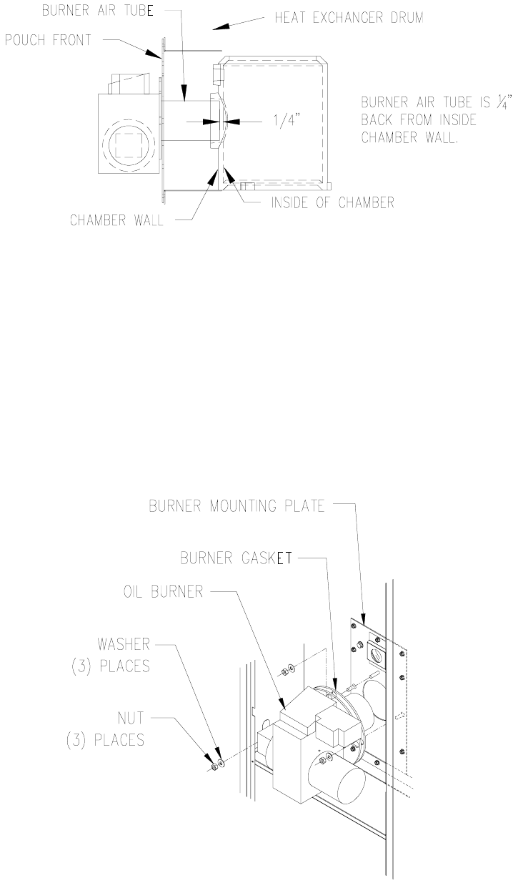
5) Rough handling of the furnace may occur while in transit. Under some
conditions, the combustion chamber can shift out of position. The chamber
should seat properly on the base of the heat exchanger. Check for proper
alignment of the burner air tube with the circular opening in the combustion
chamber and trial fit the burner to check the insertion depth of the oil burner into
the combustion chamber. It may be necessary to remove the burner mounting
plate to get sufficient access to the chamber.
The end of the burner air tube should be inserted no farther than 1/4 inch
back from the inside surface of the combustion chamber, refer to Figure 1.
DO NOT allow the burner head, at the end of the burner air tube, to physically
touch or protrude into the chamber. High temperatures in the combustion
chamber can result in damage to the tube, the burner head, or both. A distance
greater than 1/4 inch back from the inside chamber wall may cause oil spray
impingement on the combustion chamber wall and subsequent sooting and the
formation of carbon char deposits.
Only qualified service personnel shall perform installation and service.
4
Figure 1: Side View of Correct Burner Insertion into Combustion Chamber
6) Reinstall the burner mounting plate, if removed, and push the burner flange
gasket (included with the burner) on to the burner mounting plate threaded studs.
Seat the gasket against the mounting plate.
7) Reusing the fasteners removed in step (4) [three (3), 5/16 in. brass hex nuts and
three (3) steel flat washers], install and secure the burner to the mounting studs
protruding through the burner mounting plate, refer to Figure 2. (For counterflow /
horizontal units, refer to the section of the furnace instruction manual entitled
“Horizontal / Counterflow Furnace Setup”)
Figure 2: Installing and Securing the Oil Burner to the Furnace Mounting Plate
Only qualified service personnel shall perform installation and service.
5
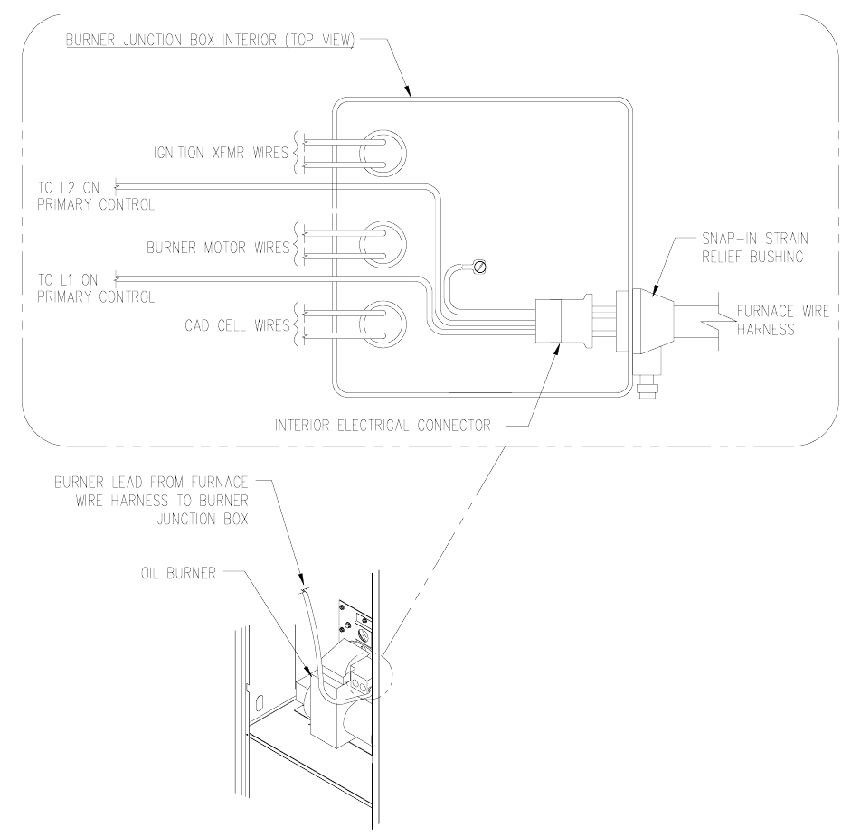
8) The burner and wiring harness are equipped with mating, three (3) pole, quick-
connect, electrical couplings. To make the connection between the burner wiring
harness and the furnace wiring harness, open the burner junction box cover (the
oil primary control serves as the cover) and remove a knockout slug from the
right-hand side of the burner junction box.
9) Insert the electrical coupling from the furnace wiring harness through the
knockout hole in the burner junction box. Snap together the furnace electrical
coupling with the oil burner electrical coupling, refer to Figure 3.
Figure 3: Connecting the Furnace Wiring Harness to the Burner Wiring Harness
Only qualified service personnel shall perform installation and service.
6
NOTICE: On the horizontal / counterflow furnace wiring harness, remove
the lock-ring from the end of the flexible metal conduit connector BEFORE
connecting the electrical couplings.
10) On the highboy and lowboy furnace wiring harnesses, snap the strain relief fitting
into the knockout opening in the burner junction box. On the horizontal /
counterflow furnace wiring harness, insert the conduit fitting through the
knockout opening in the burner junction box and thread on the lock-ring from the
inside of the junction box. Tighten the lock-ring until it is snug.
11) Close and secure the junction box cover on the burner.
The oil burner provided with this furnace requires additional installation, set-up, and
proper adjustment. Refer to the furnace instruction manual and the oil burner
manufacturer’s operating instructions for detailed information on the following items.
• Completion of fuel line connections to burner
• Initial firing of burner
• Adjusting the fuel pump pressure
• Setting the draft control
• Adjusting the burner combustion air
